Rod end male thread. With rubber bumper 056(9/16") 075(3/4") 106(1 1/16") 150(1 1/2") 250(2 1/2") 300(3")
|
|
|
- Audrey King
- 5 years ago
- Views:
Transcription
 Page Double acting Single acting Single rod Double rod Single rod (/\") (1 1/\") 00(\") 0( 1/\") 00(\") 00(\") 01(1/8\"), 06(/8\"),")
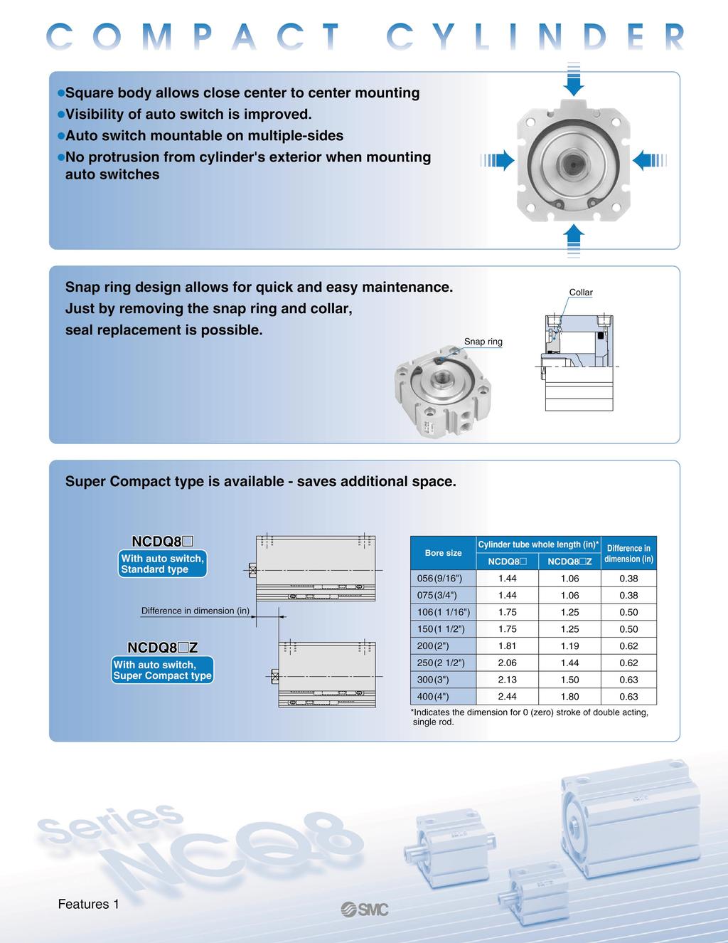
1 T.ID0-1 New ompact ylinder Series NQ8 ore size: 06(9/16 ),(/ ),106(1 1/16 ),(1 1/ ) 00( ),0( 1/ ),00( ),00( ) Now available in 00 ( ) and 00 ( ) bore sizes Standard type ctuation Style uilt-in magnet Rod end male thread With rubber bumper ore size Standard stroke (in) Page Double acting Single acting Single rod Double rod Single rod (/") (1 1/") 00(") 0( 1/") 00(") 00(") 01(1/8"), 06(/8"), 0(1/"), (/"), 07(/8"), (7/8"), (1/"), (1"), 1(1 1/"), (1 1/"), ("), 00("), 0( 1/"), 00("), 0( 1/"), 00(") 01(1/8"), 06(/8"), 0(1/"), (/"), 07(/8"), (7/8"), (1/"), (1"), 1(1 1/"), (1 1/"), ("), 00(") 1 1 Super ompact ctuation Style ore size Standard stroke (in) Page Double acting Single acting Single rod Single rod (/") (1 1/") 00(") 0( 1/") 00(") 00(") 0(1/"), (/"), 07(/8"), (7/8"), (1/"), (1"), (1 1/"), ("), 00("), 00("), 0( 1/"), 00(") 0(1/"), 07(/8"), (1/"), (/"), (7/8"), (1"), (1 1/"), ("), 00(") 06(/8"), 1(1 1/"), 0( 1/"), 06(/8"), 1(1 1/"), 1 Note) uilt-in magnet type has a minimum stroke of 0 (1/"). Super ompact type is only available with a magnet. 00 (") and 00 ("): vailable for double acting type only.
2
3 ompact ylinder Double cting, Single Rod Series NQ8 ore size: 06(9/16 ), (/ ), 106(1 1/16 ), (1 1/ ), 00( ), 0( 1/ ), 00( ), 00( ) Without auto switch With auto switch E M N uilt-in magnet Stroke (in) 1/8" 1/" /8" 1/" NQ8 NDQ8 06 Stroke (in) /8" /" 7/8" 1" Mounting Through-hole oth ends tapped Rear clevis Screw clearance hole, front mount Screw clearance hole, rear mount Screw clearance hole, through Overall length type Nil Z Standard Super ompact 1 00 How to Order Z Stroke (in) 1 1/" 1 1/" " " ylinder stroke (in) Stroke (in) 1/" " 1/" " Note 1) With auto switch is available on strokes 0(1/") and greater. pplicable uto Switches Type Solid state switch Special function Diagnostic indication (-color display) Water resistant (-color display) Electrical entry Grommet Grommet Indicator light Yes Nominal bore size 06 9/16" /" /16" 1 1/" 00 " 0 1/" 00 " 00 " Wiring (output) -wire (NPN) -wire (PNP) -wire -wire (NPN) -wire (PNP) -wire V Load voltage D V, 1 V 1 V V, 1 V 1 V Grommet -wire Yes (NPN equiv.) V No V, 1 V -wire V Yes 1 V *Lead wire length symbols: 0in (0. m) Nil (Example) M9NW 9in (1 m) M M9NWM 118in ( m) L M9NWL 197in ( m) Z M9NWZ Reed switch V M9W ody option Nil M S X-Option Nil X6 X Standard High temp. With scraper Number of auto switches Nil pcs. S 1 pc. n n pcs. uto switch type Without auto switch Nil (uilt-in magnet cylinder) *Refer to the table below for auto switch model numbers. *uto switches are shipped together, (but not assembled). Standard (Female rod end) Rubber bumper Male rod end Note ) Stroke will be reduced by 0.06" for rubber bumper type. *ombination of body options(m) is available. uto switch model Perpendicular M9NV M9PV M9V M9NWV M9PWV M9WV 96V 90V 9V In-line M9N M9P M9 M9NW M9PW M9W F (0.m) (Nil) Lead wire length (in)* 9(1m) 118(m) (M) (L) Note ) X6: Not available with magnet. *Refer to page (m) (Z) pplicable load I circuit I circuit Relay, PL I circuit I circuit Relay, PL *Solid state switches marked with a symbol are produced upon receipt of order. *9 in (1 m: M): vailable in the D-M9 W(V) only. 1
 Double acting, Single rod ir 00PSI (.1MPa) 00PSI (1.MPa) Minimum operating pressure 11PSI (0.07MPa) 8PSI (0.")
4 Series NQ8 Specifications Double acting, Single rod ore size (/") (1 1/") 00(") 0( 1/") 00(") 00(") Piping size #10-UNF #10-UNF NPT1/8 NPT1/8 NPT1/8 NPT1/ NPT1/ NPT/8 Type ction Fluid Proof pressure Maximum operating pressure Pneumatic (Non-lube) Double acting, Single rod ir 00PSI (.1MPa) 00PSI (1.MPa) Minimum operating pressure 11PSI (0.07MPa) 8PSI (0.0MPa) mbient and Without auto switch 1 to F(-10 to 6 ) (No freezing) fluid temperature With auto switch 1 to 10 F(-10 to 60 ) (No freezing) ushion Rod end thread Rubber bumper () Female thread Rod end thread tolerance Stroke tolerance Mounting NSI/SME to +0.0 in (+1.0mm) Through-hole (), oth ends tapped (), levis, SH (E,M,N) Piston speed to 0in/sec (0 to 00mm/s) to 11.8in/sec (0 to 00mm/s) pplicable Stroke ore size Standard stroke (/") 01(1/8"), 0(1/"), 07(/8"), (1/") (1 1/") 06(/8"), (/"), (7/8"), (1") 00(") 1(1 1/"), (1 1/"), ("), 00(") 0( 1/") 0( 1/"), 00("), 0( 1/"), 00(") 00(") 00(") With auto switch is available on strokes 0(1/") and greater. Unit: inch Theoretical Output Table OUT IN Unit:lbf ore size (in) (/") (1 1/") 00(") 0( 1/") 00(") 00(") Operating direction IN OUT IN OUT IN OUT IN OUT IN OUT IN OUT IN OUT IN OUT (0.) Operating pressure/psi (MPa) 7(0.) 1(1.0) (1.)
5 Weight Table Product s Weight (Double cting, Single Rod, Without uto Switch) 01 (1/8") (1/") (/8") (1/") (/8") (/") (7/8") (1") (1 1/") (1 1/") (") (") ( 1/") (") ( 1/") (") (OZ) NQ8 06- NQ8 - NQ NQ8 - NQ8 00- NQ8 0- NQ8 00- NQ8 00- Product s Weight (Double cting, Single Rod, With uto Switch) (OZ) NDQ8 06- NDQ8 - NDQ NDQ8 - NDQ8 00- NDQ8 0- NDQ8 00- NDQ8 00- Stroke Stroke Product s Weight (Double cting, Single Rod, With uto Switch, Super ompact) 01 (1/8") 0 (1/") (/8") (1/") (/8") (/") (7/8") (1") (1 1/") (1 1/") (") (") ( 1/") (") ( 1/") (") (OZ) NDQ8 Z06- NDQ8 Z- NDQ8 Z106- NDQ8 Z- NDQ8 Z00- NDQ8 Z0- NDQ8 Z00- NDQ8 Z00- Stroke 01 (1/8") 0 (1/") 07 (/8") (1/") 06 (/8") (/") (7/8") (1") 1 (1 1/") (1 1/") (") 00 (") 0 ( 1/") 00 (") 0 ( 1/") 00 (") Optional Weight (/") (1 1/") 00(") 0( 1/") 00(") 00(") ore size levis Unit: OZ Series NQ8 ompact ylinder Double cting, Single Rod
6 Series NQ8 llowable Kinetic Energy 00 0 Load weight (lbf) (") 00 (") 0 ( 1/") 00 (") (1 1/") (/") llowable lateral load at rod end Without uto Switch llowable lateral load for rod end : W (lbf) ylinder stroke (inch) Piston speed (inch/sec) With uto Switch llowable lateral load for rod end : W (lbf) ylinder stroke (inch) With uto Switch, Super ompact llowable lateral load for rod end : W (lbf) ylinder stroke (inch) W (Mounting orientation: Horizontal)
7 ompact ylinder Double cting, Single Rod Series NQ8 Mounting olt Mounting method: Mounting bolt for through-hole style of NQ8 is available as an option. Mounting bolt D Mounting olt Size for NQ806 to 00- (Without uto Switch) D NQ NQ NQ olt size order number / #-0UN-/ 7/8 7/ /8 1 1/8 1 1/ 1 1/ 1 /8 1 /8 1 1/ 1 1/ 1/8 1/8 /8 /8 /8 /8 1/8 1/8 /8 /8 / #6-UN-/ 7/8 7/ /8 1 1/8 1 1/ 1 1/ 1 /8 1 /8 1 1/ 1 1/ 1/8 1/8 /8 /8 /8 /8 1/8 1/8 /8 /8 1 1/8 #6-UN-1 1/8 1 1/ 1 1/ 1 /8 1 /8 1 1/ 1 1/ 1/ 1/ 1/ 1/ / / 1/ 1/ 1/ 1/ NQ NQ NQ olt size D order number 1 1/8 #10-UN-1 1/8 1 1/ 1 1/ 1 /8 1 /8 1 1/ 1 1/ 1/ 1/ 1/ 1/ / / 1/ 1/ 1/ 1/ 1 1/ #10-UN-1 1/ 1 /8 1 /8 1 1/ 1 1/ 1/8 1/8 /8 /8 7/8 7/8 /8 /8 1/8 1/8 /8 /8 1/8 1/8 1 1/ 1/-0UN-1 1/ 1/8 1/8 1/ 1/ /8 /8 7/8 7/8 /8 /8 7/8 7/8 /8 /8 7/8 7/8 /8 /8 NQ NQ D 1 1/ 1/8 1/ /8 7/8 /8 7/8 /8 7/8 /8 1/8 1/ 1/ /8 / 1/ 1/ / 1/ / 1/ / olt size order number 1/-0UN-1 1/ 1/8 1/ /8 7/8 /8 7/8 /8 7/8 /8 /16-18UN- 1/8 1/ 1/ /8 / 1/ 1/ / 1/ / 1/ /
8 Series NQ8 Mounting olt Mounting method: Mounting bolt for through-hole style of NQ8 is available as an option. Mounting bolt D Mounting olt Size for NDQ806 to 00- (With uto Switch) D NDQ NDQ NDQ /8 1/ 1/ / 1/ 1/ 1/ 1/ 1/8 1/ 1/ / 1/ 1/ 1/ 1/ 1/8 1/ 1/ /8 / 7/8 /8 /8 7/8 /8 7/8 /8 7/8 olt size order number #-0UN- 1/8 1/ 1/ / 1/ 1/ 1/ 1/ #6-UN- 1/8 1/ 1/ / 1/ 1/ 1/ 1/ #6-UN- 1/8 1/ 1/ /8 / 7/8 /8 /8 7/8 /8 7/8 /8 7/8 NDQ NDQ NDQ olt size D order number 1/8 #10-UN- 1/8 1/ 1/ 1/ 1/ /8 /8 / / 7/8 7/8 /8 /8 /8 /8 7/8 7/8 /8 /8 7/8 7/8 /8 /8 7/8 7/8 1/ #10-UN- 1/ 1/ 1/ /8 /8 / / 7/8 7/8 1/ 1/ 1/ 1/ / / 1/ 1/ 1/ 1/ 6 6 1/ 1/-0UN- 1/ /8 /8 / / 7/8 7/8 1/ 1/ 1/ 1/ / / 1/ 1/ / / 1/ 1/ / / 6 1/ 6 1/ NDQ NDQ olt size D order number 1/-0UN- 1/ 1/ /8 /8 / / 7/8 7/8 /8 /8 /8 /8 7/8 7/8 1/8 1/8 /8 /8 1/8 1/8 /8 /8 6 1/8 6 1/8 7/8 /16-18UN- 7/8 1/ 1/ /8 /8 1/ 1/ /8 /8 7/8 7/8 1/8 1/8 /8 /8 /8 /8 1/8 1/8 /8 /8 6 1/8 6 1/8 6 /8 6 /8 6
9 ompact ylinder Double cting, Single Rod Series NQ8 Mounting olt Mounting method: Mounting bolt for through-hole style of NQ8 is available as an option. Mounting bolt D Mounting olt size for NDQ8Z06 to 00- (With uto Switch, Super ompact) D NDQ8Z NDQ8Z NDQ8Z /8 1 1/ 1/8 /8 7/8 /8 1/8 /8 1/8 1 /8 1 1/ 1/8 /8 7/8 /8 1/8 /8 1/8 1/8 1/ /8 7/8 /8 7/8 1/ olt size order number #-0UN-1 /8 1 1/ 1/8 /8 7/8 /8 1/8 /8 1/8 #6-UN-1 /8 1 1/ 1/8 /8 7/8 /8 1/8 /8 1/8 #6-UN- 1/8 1/ /8 7/8 /8 7/8 1/ NDQ8Z NDQ8Z NDQ8Z olt size D order number #10-UN- 1/8 1/8 1/ 1/ /8 /8 7/8 7/8 /8 /8 7/8 7/8 /8 /8 7/8 7/8 /8 /8 #10-UN- 1/8 1/8 1/ 1/ /8 /8 7/8 7/8 /8 /8 7/8 7/8 /8 /8 7/8 7/8 /8 /8 1/-0UN- 1/8 1/8 1/ 1/ 1/ 1/ /8 /8 7/8 7/8 /8 /8 /8 /8 1/8 1/8 /8 /8 1/8 1/8 /8 /8 NDQ8Z NDQ8Z olt size D order number 1/-0UN- 1/8 1/8 1/ 1/ 1/ 1/ /8 /8 7/8 7/8 /8 /8 /8 /8 1/8 1/8 /8 /8 1/8 1/8 /8 /8 1/ /16-18UN- 1/ 1/ 1/ /8 /8 / / 7/8 7/8 1/ 1/ 1/ 1/ / / 1/ 1/ 1/ 1/ 6 6 7
10 Series NQ8 onstruction Without auto switch With auto switch Male thread!0 r t!1 y q e u o w!! i w uto switch *No spacer! for Z type Parts List No. Description 1 ylinder tube Piston Piston rod ollar Snap ring 6 ushing 7 Rubber bumper 8 Stud 9 Piston seal 10 Rod seal 11 Tube gasket 1 Spacer 1 Magnet Material Remarks luminum alloy Hard anodized luminum alloy hromated Stainless steel 06 to 106 arbon steel to 00 Hard chrome plated luminum alloy nodized arbon tool steel Phosphate coated Phosphor bronze alloy 00 to 00 NR With rubber bumper only Steel alloy Electroless nickel plated NR NR NR luminum alloy hromated, Use for with auto switch type only(no spacer for Z type) Repair Parts: Standard Seal Kit for Double cting, Single Rod ore size Kit no. Remarks (/") (1 1/") 00(") 0( 1/") 00(") 00(") NQ806-PS NQ8-PS NQ8106-PS NQ8-PS NQ800-PS NQ80-PS NQ800-PS NQ800-PS Piston seal, rod seal, and tube gasket are included. 8
11 ompact ylinder Double cting, Single Rod Series NQ8 Dimensions/NQ806 to 00 [Without uto switch] #8-UN-thread -depth 0.0-counter bore 0.1 depth sides x places dia. 0.1-through hole places rod dia #10-UNF-port places bolt circle Note) [0.16] Stroke Stroke 1/8" 1/" to " Note) With rubber bumper type, the stroke is reduced by 0.06" and the rod extension is 0.16". (/"),, (1 1/"), 00("), 0( 1/"), 00("), 00(") N-through hole places M bolt circle Z H-thread -depth J D-rod Dia. Q P-port places F For, 106 M1 E W I dia. K For 00, 00 M1 E O-counter bore R depth sides x places 0.1 Note) [0.16] +Stroke ore (/") (1 1/") 00(") 0( 1/") 00(") 00(") 1/8"st 1/"st /8" to "st D E F H #10-UNF /16-UNF /8-UNF 1/-0UNF 1/-0UNF /8-18UNF /-16UNF I J K M M N O P #10-UNF NPT1/8 NPT1/8 NPT1/8 NPT1/ NPT1/ NPT/8 Q R W Z Note) With rubber bumper type, the stroke is reduced by 0.06" and the rod extension is 0.16". 9
12 Series NQ8 Dimensions/NDQ8(Z)06 to 00 [With uto switch, Super compact] #8-UN-thread 0.6-depth 0.0-counter bore 0.1 depth sides x places dia. 0.1-through hole places rod dia #10-UNF-port places bolt circle Note) [0.16] uto switch + Stroke ore Standard Super compact Note) With rubber bumper type, the stroke is reduced by 0.06" and the rod extension is 0.16". (/"),, (1 1/"), 00("), 0( 1/"), 00("), 00(") N-through hole places M bolt circle Z H-thread -depth J D-rod dia. Q P-port places F For, 106 M1 E W I dia. K uto switch For 00, 00 M1 E O-counter bore R depth sides x places 0.1 Note) [0.16] + Stroke ore (/") (1 1/") 00(") 0( 1/") 00(") 00(") Super Super compact D E F H I J K M1 M N O P Q R W Z Standard compact Standard 1/"st /8"to"st #10-UNF #10-UNF /16-UNF NPT1/ /8-UNF 1/-0UNF 1/-0UNF /8-18UNF /-16UNF NPT1/8 NPT1/8 NPT1/ NPT1/ NPT/ Note) With rubber bumper type, the stroke is reduced by 0.06" and the rod extension is 0.16". 10
13 ompact ylinder Double cting, Single Rod Series NQ8 Dimensions/Mounting oth ends tapped N(D)Q8 - ()(M) ore O1 R O1-Thread R R (/") (1 1/") 00(") 0( 1/") 00(") 00(") #-0UN #6-UN #6-UN #10-UN #10-UN 1/-0UN 1/-0UN /16-18UN Note) Fully threaded tap for 01 stroke Rear clevis/n(d)q8(z), (/"),, (1 1/"), 00("), 0( 1/"), 00("), 00(") D E F øg H10 through øm J±0.00 K ±0.01 ore (/") (1 1/") 00(") 0( 1/") 00(") 00(") D E F G /16 /16 /16 /8 /8 /8 /8 /8 J K M Screw clearance hole, front mount/ N(D)Q8E(Z) Screw clearance hole, rear mount/ N(D)Q8M(Z) -øe Screw clearance hole, through/n(d)q8n(z) -øe -øe ore (/") (1 1/") 00(") 0( 1/") 00(") 00(") E Dimensions/Male rod end Male rod end N(D)Q8 - ()M K H-Thread L ore (/") (1 1/") 00(") 0( 1/") 00(") 00(") H #8-UN #10-UNF /16-UNF /8-UNF 1/-0UNF 1/-0UNF /8-18UNF /-16UNF L K
14 ompact ylinder Double cting, Double Rod Series NQ8W ore size: 06(9/16 ), (/ ), 106(1 1/16 ), (1 1/ ), 00( ), 0( 1/ ), 00( ), 00( ) How to Order Without auto switch With auto switch uilt-in magnet E N NQ8W NDQ8W Double rod Mounting Through-hole oth ends tapped Screw clearance hole, front mount Screw clearance hole, rear mount Nominal bore size 06 9/16" /" /16" 1 1/" 00 " 0 1/" 00 " 00 " 0 0 M9W S X-Option Nil X6 X Standard High temp. With scraper Note ) X6: Not available with magnet. *Refer to page 6. Number of auto switches Nil pcs. S 1 pc. n n pcs. uto switch type Without auto switch Nil (uilt-in magnet cylinder) *Refer to the table below for auto switch model numbers. *uto switches are shipped together, (but not assembled). pplicable uto Switches Type Solid state switch Special function Stroke (in) 1/8" 1/" /8" 1/" 06 Electrical entry Stroke (in) /8" /" 7/8" 1" Indicator light 1 00 Wiring (output) ylinder stroke (in) Stroke (in) 1 1/" 1 1/" " " Load voltage D Note 1) With switch is available on strokes 0(1/") and greater. Grommet -wire Yes (NPN equiv.) V No V, 1 V -wire V Yes 1 V *Lead wire length symbols: 0in (0. m) Nil (Example) M9NW 9in (1 m) M M9NWM 118in ( m) L M9NWL 197in ( m) Z M9NWZ Reed switch 1 Diagnostic indication (-color display) Water resistant (-color display) Grommet Grommet Yes -wire (NPN) -wire (PNP) -wire -wire (NPN) -wire (PNP) -wire V V, 1 V 1 V V, 1 V 1 V Stroke (in) 1/" " 1/" " V uto switch model Perpendicular M9NV M9PV M9V M9NWV M9PWV M9WV 96V 90V 9V ody option Nil M In-line Standard (Female rod end) Rubber bumper Male rod end Note ) Stroke will be reduced by 0.06" for rubber bumper type. *ombination of body options(m) is available. M9N M9P M9 M9NW M9PW M9W F (0.m) (Nil) Lead wire length (in)* 9(1m) 118(m) (M) (L) 197(m) (Z) pplicable load I circuit I circuit Relay, PL I circuit I circuit Relay, PL *Solid state switches marked with a symbol are produced upon receipt of order. *9 in (1 m: M): vailable in the D-M9 W(V) only.
 (1 1/\") 00(\") 0( 1/\") #10-UNF #10-UNF")
15 ompact ylinder Double cting, Double Rod Series NQ8W Specifications Double acting, Double rod ore size Piping size Type ction Fluid Proof pressure Maximum operating pressure Minimum operating pressure mbient and fluid temperature Without auto switch With auto switch ushion Rod end thread Rod end thread tolerance Stroke tolerance Mounting Piston speed (/") (1 1/") 00(") 0( 1/") #10-UNF #10-UNF NPT1/8 NPT1/8 NPT1/8 NPT1/ Pneumatic (Non-lube) Double acting, Double rod ir 00PSI (.1MPa) 00PSI (1.MPa) 11PSI (0.07MPa) 8PSI (0.0MPa) 00(") NPT1/ 00(") NPT/8 1 to F(-10 to 6 ) (No freezing) 1 to 10 F(-10 to 60 ) (No freezing) Rubber bumper () Female thread NSI/SME to +0.0 in (+1.0mm) Through-hole (), oth ends tapped (), levis, SH (E,N) to 11.8in/sec to 0in/sec (0 to 00mm/s) (0 to 00mm/s) pplicable Stroke Theoretical Output Table ore size (/") (1 1/") 00(") 0( 1/") 00(") 00(") Unit: inch Standard stroke 01(1/8"), 0(1/"), 07(/8") (1/"), 06(/8"), (/") (7/8"), (1"), 1(1 1/") (1 1/"), ("), 00(") 0( 1/"), 00(") 0( 1/"), 00(") With switch is available on strokes 0(1/") and greater. ore size (in) (/") (1 1/") 00(") 0( 1/") 00(") 00(") (0.) Operating pressure/psi (MPa) 7(0.) 1(1.0) (1.) Unit:lbf Weight Table Product s Weight (Double cting, Double Rod, Without Switch) Stroke NQ8W 06- NQ8W - NQ8W 106- NQ8W - NQ8W 00- NQ8W 0- NQ8W 00- NQ8W 00- (1/8") (1/") (/8") (1/") (/8") (/") (7/8") (1") (1 1/") (1 1/") (") (") ( 1/") (") ( 1/") (OZ) 00 (") Product s Weight (Double cting, Double Rod, With Switch) Stroke (1/8") (1/") (/8") (1/") (/8") (/") (7/8") NDQ8W 06- NDQ8W - NDQ8W 106- NDQ8W - NDQ8W 00- NDQ8W 0- NDQ8W 00- NDQ8W (1") (1 1/") (1 1/") (") (") ( 1/") (") ( 1/") (OZ) 00 (")
16 Series NQ8W llowable Kinetic Energy 00 0 Load weight (lbs) (") 00 (") 0 ( 1/") 00 (") (1 1/") (/") Piston speed (inch/sec) llowable lateral load at rod end Without uto Switch llowable lateral load for rod end : W (lbf) ylinder stroke (inch) With uto Switch llowable lateral load for rod end : W (lbf) ylinder stroke (inch) W (Mounting orientation : Horizonal) 1
17 ompact ylinder Double cting, Double Rod Series NQ8W Mounting olt Mounting method: Mounting bolt for through-hole style of NQ8W is available as an option. Mounting bolt D Mounting olt Size for NQ8W06 to 00- (Without uto Switch) D NQ8W NQ8W NQ8W olt size order number 7/8 #-0UN-7/ /8 1 1/8 1 1/ 1 1/ 1 /8 1 /8 1 1/ 1 1/ 1/ 1/ 1/ 1/ / / 1/ 1/ / / 1/ 1/ / / 7/8 #6-UN-7/ /8 1 1/8 1 1/ 1 1/ 1 /8 1 /8 1 1/ 1 1/ 1/ 1/ 1/ 1/ / / 1/ 1/ / / 1/ 1/ / / 1 1/8 #6-UN-1 1/8 1 1/ 1 1/ 1 /8 1 /8 1 1/ 1 1/ 1/ 1/ 1/ 1/ / / 1/ 1/ 1/ 1/ NQ8W NQ8W NQ8W olt size D order number 1 1/ #10-UN-1 1/ 1 /8 1 /8 1 1/ 1 1/ 1/8 1/8 /8 /8 7/8 7/8 /8 /8 1/8 1/8 /8 /8 1/8 1/8 1 /8 #10-UN-1 /8 1 1/ 1 1/ 1/8 1/8 1/ 1/ 1/ 1/ / / 1/ 1/ / / 1/ 1/ / / 1/ 1/ 1/-0UN- 1/8 1/8 1/ 1/ 1/ 1/ / / 1/ 1/ 1/ 1/ 1/ 1/ 1/ 1/ NQ8W NQ8W D 1/8 1/ 1/ / 1/ 1/ 1/ 1/ 1/8 1/ 1/ /8 / 7/8 /8 /8 7/8 /8 7/8 /8 7/8 olt size order number 1/-0UN- 1/8 1/ 1/ / 1/ 1/ 1/ 1/ /16-18UN- 1/8 1/ 1/ /8 / 7/8 /8 /8 7/8 /8 7/8 /8 7/8 1
18 Series NQ8W Mounting olt Mounting method: Mounting bolt for through-hole style of NQ8W is available as an option. Mounting bolt D Mounting olt Size for NDQ8W06 to 00- (With uto Switch) NDQ8W NDQ8W NDQ8W D 1/8 1/ 1/ /8 7/8 /8 /8 1/8 /8 1/8 /8 1/8 1/ 1/ /8 7/8 /8 /8 1/8 /8 1/8 /8 1/8 1/ 1/ /8 / 7/8 /8 /8 7/8 /8 7/8 /8 7/8 olt size order number #-0UN- 1/8 1/ 1/ /8 7/8 /8 /8 1/8 /8 1/8 /8 #6-UN- 1/8 1/ 1/ /8 7/8 /8 /8 1/8 /8 1/8 /8 #6-UN- 1/8 1/ 1/ /8 / 7/8 /8 /8 7/8 /8 7/8 /8 7/8 NDQ8W NDQ8W NDQ8W olt size D order number 1/ #10-UN- 1/ 1/ 1/ /8 /8 / / 7/8 7/8 1/ 1/ 1/ 1/ / / 1/ 1/ 1/ 1/ 6 6 #10-UN- 1/ 1/ /8 /8 / / 7/8 7/8 /8 /8 /8 /8 7/8 7/8 1/8 1/8 /8 /8 1/8 1/8 /8 /8 6 1/8 6 1/8 /8 1/-0UN- /8 / / 7/8 7/8 1/ 1/ /8 /8 /8 /8 7/8 7/8 1/8 1/8 /8 /8 7/8 7/8 /8 /8 7/8 7/8 6 /8 6 /8 NDQ8W NDQ8W olt size D order number /8 1/-0UN- /8 / / 7/8 7/8 1/ 1/ /8 /8 7/8 7/8 7/8 7/8 1/8 1/8 /8 /8 7/8 7/8 /8 /8 7/8 7/8 6 /8 6 /8 /16-18UN- 1/ 1/ /8 /8 1/ 1/ /8 /8 / / 1/ 1/ 1/ 1/ / / 1/ 1/ / / 6 1/ 6 1/ 6 / 6 / 16
19 ompact ylinder Double cting, Double Rod Series NQ8W onstruction Without auto switch With auto switch Male thread y w e u oi! r q!0! e!! t!!9!1!6!8!7 uto switch For stroke 01(1/8")~(/") For stroke (7/8")~00(") Parts List No. Description 1 ylinder tube Piston Ring Piston Piston Rod Piston Rod 6 Piston Rod 7 ollar 8 Snap ring 9 ushing 10 Rubber bumper 11 Stud 1 Piston gasket 1 Piston seal 1 Rod seal 1 Tube gasket 16 Gasket 17 Gasket Super low head 18 cap bolt 19 Magnet Material Remarks luminum alloy Hard anodized Stainless steel 00 and 00 only luminum alloy hromated Stainless steel 06 to 106 arbon steel to 00, Hard chrome plated Stainless steel 06 to 106 arbon steel to 00, Hard chrome plated arbon steel 00 and 00 only luminum alloy nodized arbon tool steel Phosphate coated Phosphor bronze alloy 00 to 00 NR Use for with rubber bumper only Steel alloy Electroless nickel plated NR to 00 NR NR NR NR 00 and 00 only NR 00 and 00 only arbon steel 00 and 00 only Repair Parts: Standard Seal Kit for Double cting, Double Rod ore size Kit no. Remarks (/") (1 1/") 00(") 0( 1/") 00(") 00(") NQ8W06-PS NQ8W-PS NQ8W106-PS NQ8W-PS NQ8W00-PS NQ8W0-PS NQ8W00-PS NQ8W00-PS Piston seal, rod seal and tube gasket are included. 17
20 Series NQ8W Dimensions/NQ8W06 to 00 [Without uto switch] 0.0-counter bore 0.1 depth sides x places dia. 0.1-through hole places rod dia. 0. #10-UNF-port places 0. #8-UN-thread 0.6-depth + Stroke Stroke Note) [0.10+Stroke] Note) With rubber bumper type, the stroke is reduced by 0.06" and the rod extension is 0.16". (/"),, (1 1/"), 00("), 0( 1/"), 00("), 00(") For, 106 N-through hole places M bolt circle Z J D-rod dia. Q Q P-port places -depth H-thread M1 E W bolt circle rod dia. 0.1 Note) [0.16] For 00, 00 I dia. K D-rod dia. M1 E O-counter bore R depth sides x places 0.1 Note) [0.16] + Stroke Stroke [0.10+Stroke] Note) ore (/") (1 1/") 00(") 0( 1/") 00(") 00(") D E H #10-UNF /16-UNF /8-UNF 1/-0UNF 1/-0UNF /8-18UNF /-16UNF I J K M M N O P #10-UNF NPT1/8 NPT1/8 NPT1/8 NPT1/ NPT1/ NPT/8 Q R W Z Note) With rubber bumper type, the stroke is reduced by 0.06" and the rod extension is 0.16". 18
21 M bolt circle ompact ylinder Double cting, Double Rod Series NQ8W Dimensions/NDQ8W06 to 00 [With uto switch] 0.0-counter bore 0.1 depth sides x places dia. 0.1-through hole places rod dia. 0. #10-UNF-port places 0. #8-UN-thread 0.6-depth 0.88 bolt circle Note) With rubber bumper type, the stroke is reduced by 0.06" and the rod extension is 0.16". N-through hole places Z J Q P-port places Q -depth H-thread M1 E W Note) [0.16] uto switch Stroke 0.-rod dia Stroke Note) [0.10+Stroke] (/"),, (1 1/"), 00("), 0( 1/"), 00("), 00(") For, 106 For 00, 00 I dia. K D-rod dia. uto switch D-rod dia. M1 E O-counter bore R depth sides x places 0.1 Note) [0.16] + Stroke Stroke Note) [0.10+Stroke] ore (/") (1 1/") 00(") 0( 1/") 00(") 00(") D E H #10-UNF /16-UNF /8-UNF 1/-0UNF 1/-0UNF /8-18UNF /-16UNF I J K M M N O P #10-UNF NPT1/8 NPT1/8 NPT1/8 NPT1/ NPT1/ NPT/8 Q R W Z Note) With rubber bumper type, the stroke is reduced by 0.06" and the rod extension is 0.16". 19
22 Series NQ8W Dimensions/N(D)Q8W oth ends tapped N(D)Q8W - ()(M) O1-Thread R R ore O1 R (/") (1 1/") 00(") 0( 1/") 00(") 00(") #-0UN #6-UN #6-UN #10-UN #10-UN 1/-0UN 1/-0UN /16-18UN Note) Fully threaded tap for 01 stroke Screw clearance hole front mount/n(d)q8we -øe ore E Screw clearance hole rear mount/n(d)q8wn (/") (1 1/") 00(") 0( 1/") 00(") 00(") øe Dimensions/Male rod end Male rod end N(D)Q8W - ()M ore H L K H-Thread (/") (1 1/") 00(") 0( 1/") 00(") 00(") #8-UN #10-UNF /16-UNF /8-UNF 1/-0UNF 1/-0UNF /8-18UNF /-16UNF K L 0
23 ompact ylinder Single cting, Single Rod Series NQ8 ore size: 06(9/16 ), (/ ), 106(1 1/16 ), (1 1/ ), 00( ), 0( 1/ ) Without auto switch With auto switch E M N uilt-in magnet NQ8 NDQ8 Mounting Through-hole oth end tapped Rear clevis Screw clearance hole, front mount Screw clearance hole, rear mount Screw clearance hole, through pplicable uto Switches Type Solid state switch Special function Diagnostic indication (-color display) Water resistant (-color display) Stroke (in) 1/8" 1/" /8" 1/" 06 Stroke (in) /8" /" 7/8" 1" Stroke (in) 1 1/" 1 1/" " " Note) With switch is available on strokes 0(1/") and greater. Electrical entry Grommet Grommet Overall length type Nil Z Indicator light Yes Standard Super ompact Nominal bore size 06 9/16" /" /16" 1 1/" 00 " 0 1/" ylinder stroke (in) Wiring (output) -wire (NPN) -wire (PNP) -wire -wire (NPN) -wire (PNP) -wire V Load voltage D V, 1 V 1 V V, 1 V 1 V Grommet -wire Yes (NPN equiv.) V No V, 1 V -wire V Yes 1 V *Lead wire length symbols: 0in (0. m) Nil (Example) M9NW 9in (1 m) M M9NWM 118in ( m) L M9NWL 197in ( m) Z M9NWZ Reed switch How to Order V uto switch model Perpendicular M9NV M9PV M9V M9NWV M9PWV M9WV 96V 90V 9V S S In-line M9N M9P M9 M9NW M9PW M9W F9 0(0.m) (Nil) M9W ody option Nil M ctuation S Single acting, Spring return T Single acting, Spring extend S Number of auto switches Nil pcs. S 1 pc. n n pcs. uto switch type Without auto switch Nil (uilt-in magnet cylinder) *Refer to the table below for auto switch model numbers. *uto switches are shipped together, (but not assembled). Standard (Female rod end) Male rod end Lead wire length (in)* 9(1m) (M) 118(m) (L) 197(m) (Z) pplicable load I circuit I circuit Relay, PL I circuit I circuit Relay, PL *Solid state switches marked with a symbol are produced upon receipt of order. *9 in (1 m: M): vailable in the D-M9 W(V) only. 1

 1 to F(-10 to 6 ) (No freezing) 1 to 10 F(-10 to 60 ) (No freezing) Not vailable NSI/SME 1.1-1989 0 to +0.0 in (+1.")
24 Series NQ8 Specifications Single acting, Single acting, Single return Spring extend ore size Piping size Type Fluid Proof pressure Maximum operating pressure Minimum operating pressure mbient and fluid temperature ushion Rod end thread tolerance Stroke tolerance Mounting Piston speed Without auto switch With auto switch #10-UNF 7PSI (0.MPa) (/") (1 1/") 00(") #10-UNF NPT1/8 NPT1/8 NPT1/8 Pneumatic (Non-lube) ir 00PSI (.1MPa) 00PSI (1.MPa) 6PSI (0.18MPa) PSI (0.1MPa) 1 to F(-10 to 6 ) (No freezing) 1 to 10 F(-10 to 60 ) (No freezing) Not vailable NSI/SME to +0.0 in (+1.0mm) Through-hole (), oth ends tapped () to 0in/sec (0 to 00mm/s) 0( 1/") NPT1/ 19PSI (0.1MPa) pplicable Stroke ore size (/") (1 1/") 00(") 0( 1/") With switch is available on strokes 0(1/") and greater. Standard stroke 01(1/8"), 0(1/"), 07(/8"), (1/") 06(/8"), (/"), (7/8"), (1") 1(1 1/"), (1 1/"), ("), 00(") Unit: inch OUT IN Spring Reaction Force Theoretical Output Table ore size (in) (/") (1 1/") 00(") 0( 1/") Stroke 01(1/8") to (1") 1(1 1/") to 00(") 01(1/8") to (1") 1(1 1/") to 00(") 01(1/8") to (1") 1(1 1/") to 00(") 01(1/8") to (1") 1(1 1/") to 00(") 01(1/8") to (1") 1(1 1/") to 00(") 01(1/8") to (1") 1(1 1/") to 00(") Spring reaction force Inlet Outlet Unit:lbf Single cting, Spring Return ore size (in) (/") (1 1/") 00(") 0( 1/") (0.) Single cting, Spring Extend ore size (in) (/") (1 1/") 00(") 0( 1/") (0.) Pressure (MPa) 7(0.) Pressure (MPa) 7(0.) (1.0) (1.0) (1.) (1.) Unit:lbf Unit:lbf Optional Weight ore size(in) (/") (1 1/") 00(") 0( 1/") levis Unit: OZ
25 ompact ylinder Single cting, Single Rod Series NQ8 Weight Table Product, s Weight (Single cting, Spring Return, Without uto Switch) Stroke NQ8 06- S NQ8 - S NQ S NQ8 - S NQ8 00- S NQ8 0- S 01 (1/8") (1/") (/8") (1/") (/8") (/") (7/8") (1") (1 1/") (1 1/") (") (OZ) 00 (") Product, s Weight (Single cting, Spring Return, With uto Switch) Stroke NDQ8 06- S NDQ8 - S NDQ S NDQ8 - S NDQ8 00- S NDQ8 0- S (1/8") (1/") (/8") (1/") (/8") (/") (7/8") (1") (1 1/") (1 1/") (") (OZ) 00 (") Product, s Weight (Single cting, Spring Return, With uto Switch, Super ompact) Stroke (1/8") (1/") (/8") (1/") (/8") (/") (7/8") (1") NDQ8 Z06- S NDQ8 Z- S NDQ8 Z106- S NDQ8 Z- S NDQ8 Z00- S NDQ8 Z0- S (1 1/") (1 1/") (") (OZ) 00 (") Product, s Weight (Single cting, Spring Extend, Without uto Switch) Stroke (1/8") (1/") (/8") (1/") (/8") (/") (7/8") NQ8 06- T NQ8 - T NQ T NQ8 - T NQ8 00- T NQ8 0- T (1") (1 1/") (1 1/") (") (OZ) 00 (") Product, s Weight (Single cting, Spring Extend, With uto Switch) Stroke NDQ8 06- T NDQ8 - T NDQ T NDQ8 - T NDQ8 00- T NDQ8 0- T (1/8") (1/") (/8") (1/") (/8") (/") (7/8") (1") (1 1/") (1 1/") (") (OZ) 00 (") Product, s Weight (Single cting, Spring Extend, With uto Switch, Super ompact) Stroke (1/8") (1/") (/8") (1/") (/8") (/") (7/8") (1") NDQ8 Z06- T NDQ8 Z- T NDQ8 Z106- T NDQ8 Z- T NDQ8 Z00- T NDQ8 Z0- T (1 1/") (1 1/") (") (OZ) 00 (")
26 Series NQ8 Mounting olt Mounting method: Mounting bolt for through-hole style of NQ8 is available as an option. Mounting bolt D Mounting olt Size for NQ806 to 0- S(Without uto switch) D NQ806-01S 0S 07S S 06S S S S 1S S S 00S NQ8-01S 0S 07S S 06S S S S 1S S S 00S NQ S 0S 07S S 06S S S S 1S S S 00S /8 1 1/ 1 /8 1 1/ / 1/ 1/ 1 1 1/8 1 1/ 1 /8 1 1/ / 1/ 1/ 1 1/8 1 1/ 1 /8 1 1/ 7/8 /8 /8 olt size order number #-0UN-1 1 1/8 1 1/ 1 /8 1 1/ / 1/ 1/ #6-UN-1 1 1/8 1 1/ 1 /8 1 1/ / 1/ 1/ #6-UN-1 1/8 1 1/ 1 /8 1 1/ 7/8 /8 /8 NQ8-01S 0S 07S S 06S S S S 1S S S 00S NQ800-01S 0S 07S S 06S S S S 1S S S 00S NQ80-01S 0S 07S S 06S S S S 1S S S 00S D 1 1/8 1 1/ 1 /8 1 1/ 1/ 1/ / 1 1/ 1 /8 1 1/ 1/8 1/ 1/ / 1 1/ 1/8 1/ 1/ / 1/ olt size order number #10-UN-1 1/8 1 1/ 1 /8 1 1/ 1/ 1/ / #10-UN-1 1/ 1 /8 1 1/ 1/8 1/ 1/ / 1/-0UN-1 1/ 1/8 1/ 1/ / 1/
27 ompact ylinder Single cting, Single Rod Series NQ8 Mounting olt Size for NDQ806 to 0- S(With uto switch) D NDQ806-0S 07S S 06S S S S 1S S S 00S NDQ8-0S 07S S 06S S S S 1S S S 00S NDQ8106-0S 07S S 06S S S S 1S S S 00S /8 1/ 1/ /8 /8 7/8 1/8 1/8 1/ 1/ /8 / /8 7/8 1/8 /8 1/8 1/ 1/ /8 / 7/8 / 1/ 1/ olt size order number #-0UN- 1/8 1/ 1/ /8 /8 7/8 1/8 #6-UN- 1/8 1/ 1/ /8 / /8 7/8 1/8 /8 #6-UN- 1/8 1/ 1/ /8 / 7/8 / 1/ 1/ NDQ8-0S 07S S 06S S S S 1S S S 00S NDQ800-0S 07S S 06S S S S 1S S S 00S NDQ80-0S 07S S 06S S S S 1S S S 00S D 1/8 1/ 1/ /8 / 7/8 / 1/ 1/ 1/ 1/ /8 / 7/8 7/8 1/8 /8 /8 1/ /8 / 7/8 1/ /8 /8 7/8 1/8 olt size order number #10-UN- 1/8 1/ 1/ /8 / 7/8 / 1/ 1/ #10-UN- 1/ 1/ /8 / 7/8 7/8 1/8 /8 /8 1/-0UN- 1/ /8 / 7/8 1/ /8 /8 7/8 1/8 Mounting olt Size for NDQ8Z06 to 0- S(With uto switch), Super compact D NDQ8Z06-0S 07S S 06S S S S 1S S S 00S NDQ8Z-0S 07S S 06S S S S 1S S S 00S NDQ8Z106-0S 07S S 06S S S S 1S S S 00S / 1/8 1/ /8 /8 7/8 1 1/ 1/8 1/ /8 /8 7/8 1/8 1/ 1/ 1/ / olt size order number #-0UN-1 1/ 1/8 1/ /8 /8 7/8 #6-UN-1 1/ 1/8 1/ /8 /8 7/8 #6-UN- 1/8 1/ 1/ 1/ / NDQ8Z-0S 07S S 06S S S S 1S S S 00S NDQ8Z00-0S 07S S 06S S S S 1S S S 00S NDQ8Z0-0S 07S S 06S S S S 1S S S 00S D 1/8 1/ 1/ 1/ / 1/8 1/ /8 7/8 /8 1/8 1/ 1/ /8 / 1/ 1/ olt size order number #10-UN- 1/8 1/ 1/ 1/ / #10-UN- 1/8 1/ 1/ 1/ / 1/-0UN- 1/8 1/ 1/ /8 / 1/ 1/
28 Series NQ8 Mounting olt Mounting method: Mounting bolt for through-hole style of NQ8 is available as an option. Mounting bolt D Mounting olt Size for NQ806 to 0- T(Without uto switch) NQ806-01T 0T 07T T 06T T T T 1T T T 00T NQ8-01T 0T 07T T 06T T T T 1T T T 00T NQ T 0T 07T T 06T T T T 1T T T 00T D 1 1/ 1 /8 1 1/ 1/8 1/ 1/ / 1 1/ 1 /8 1 1/ 1/8 1/ 1/ / 1/8 1/ 1/ /8 /8 7/8 1/8 olt size order number #-0UN-1 1/ 1 /8 1 1/ 1/8 1/ 1/ / #6-UN-1 1/ 1 /8 1 1/ 1/8 1/ 1/ / #6-UN- 1/8 1/ 1/ /8 /8 7/8 1/8 NQ8-01T 0T 07T T 06T T T T 1T T T 00T NQ800-01T 0T 07T T 06T T T T 1T T T 00T NQ80-01T 0T 07T T 06T T T T 1T T T 00T D 1/8 1/ 1/ /8 /8 7/8 1/8 1/8 1/ 1/ /8 1/ / 1/ 1/ 1/ /8 / 7/8 1/ 1/ / olt size order number #10-UN- 1/8 1/ 1/ /8 /8 7/8 1/8 #10-UN- 1/8 1/ 1/ /8 1/ / 1/ 1/-0UN- 1/ 1/ /8 / 7/8 1/ 1/ / 6
29 ompact ylinder Single cting, Single Rod Series NQ8 Mounting olt Size for NDQ806 to 0- T(With uto switch) D NDQ806-0T 07T T 06T T T T 1T T T 00T NDQ8-0T 07T T 06T T T T 1T T T 00T NDQ8106-0T 07T T 06T T T T 1T T T 00T /8 1/ 1/ /8 /8 7/8 1/8 1/ 1/ /8 / 7/8 7/8 1/8 /8 /8 /8 / 7/8 1/ /8 1/ 1/ / olt size order number #-0UN- 1/8 1/ 1/ /8 /8 7/8 1/8 #6-UN- 1/ 1/ /8 / 7/8 7/8 1/8 /8 /8 #6-UN- /8 / 7/8 1/ /8 1/ 1/ / D NDQ8-0T 07T T 06T T T T 1T T T 00T NDQ800-0T 07T T 06T T T T 1T T T 00T NDQ80-0T 07T T 06T T T T 1T T T 00T /8 / 7/8 1/ /8 1/ 1/ / / 7/8 1/ /8 1/ /8 /8 7/8 1/8 1/ /8 1/ /8 / 7/8 1/8 /8 /8 7/8 olt size order number #10-UN- /8 / 7/8 1/ /8 1/ 1/ / #10-UN- / 7/8 1/ /8 1/ /8 /8 7/8 1/8 1/-0UN- 1/ /8 1/ /8 / 7/8 1/8 /8 /8 7/8 Mounting olt Size for NDQ8Z06 to 0- T(With uto switch), Super compact D NDQ8Z06-0T 07T T 06T T T T 1T T T 00T NDQ8Z-0T 07T T 06T T T T 1T T T 00T NDQ8Z106-0T 07T T 06T T T T 1T T T 00T /8 1/ 1/ 1/ / 1/8 1/ 1/ /8 1/ / 1/ 1/8 1/ 1/ /8 / 7/8 / 1/ 1/ olt size order number #-0UN- 1/8 1/ 1/ 1/ / #6-UN- 1/8 1/ 1/ /8 1/ / 1/ #6-UN- 1/8 1/ 1/ /8 / 7/8 / 1/ 1/ D NDQ8Z-0T 07T T 06T T T T 1T T T 00T NDQ8Z00-0T 07T T 06T T T T 1T T T 00T NDQ8Z0-0T 07T T 06T T T T 1T T T 00T /8 1/ 1/ /8 / 7/8 / 1/ 1/ 1/8 1/ 1/ /8 / 7/8 / 1/ 1/ /8 / 7/8 1/ /8 1/ / 1/ olt size order number #10-UN- 1/8 1/ 1/ /8 / 7/8 / 1/ 1/ #10-UN- 1/8 1/ 1/ /8 / 7/8 / 1/ 1/ 1/-0UN- /8 / 7/8 1/ /8 1/ / 1/ 7
30 Series NQ8 onstruction/single cting Spring Return Without auto switch With auto switch Male thread r t y q e u o w i!0!1 uto switch Parts List No. Description 1 ylinder tube Piston Piston rod ollar Snap ring 6 ushing 7 Return spring 8 Stud 9 Piston seal 10 Spacer 11 Magnet Material Remarks luminum alloy Hard anodized luminum alloy hromated Stainless steel 06 to 106 arbon steel to 0 Hard chrome plated luminum alloy 06,, 106, 00, 0nodized Stainless steel arbon tool steel Phosphate coated Oil-impregnated sintered alloy 106 only Phosphor bronze alloy, 00, 0 only Piano wire Zinc chromated Steel alloy Electroless nickel plated NR luminum alloy hromated, Use for standard type only. Repair Parts: Seal Kit for Single cting, Spring Return ore size Kit no. Remarks (/") NQ806-S-PS NQ8-S-PS NQ8106-S-PS (1 1/") NQ8-S-PS Piston seal is included. 00(") 0( 1/") NQ800-S-PS NQ80-S-PS 8
31 ompact ylinder Single cting, Single Rod Series NQ8 onstruction/single cting Spring Extend Without auto switch With auto switch Male thread e!1 rt! y!0 wqiu!!! o uto switch Parts List No. Description 1 ylinder tube Piston Piston rod ollar Snap ring 6 ushing 7 Spacer 8 Return spring 9 Stud 10 Piston seal 11 Rod seal 1 Tube gasket 1 Spacer 1 Spacer 1 Magnet Material Remarks luminum alloy Hard anodized luminum alloy hromated Stainless steel 06 to 106 arbon steel to 0 Hard chrome plated luminum alloy nodized arbon tool steel Phosphate coated Phosphor bronze alloy 00, 0 only luminum alloy hromated Piano wire Zinc chromated Steelalloy Electroless nickel plated NR NR NR luminum alloy hromated, Use for standard type only luminum alloy hromated Repair Parts: Seal Kit for Single cting Spring Extend ore size Kit no. Remarks (/") (1 1/") 00(") 0( 1/") NQ806-T-PS NQ8-T-PS NQ8106-T-PS NQ8-T-PS NQ800-T-PS NQ80-T-PS Piston seal, rod seal and, tube gasket are included. 9
32 M bolt circle Series NQ8 Dimensions/NQ806 to 0- S [Without uto switch] #8-UN-thread 0.6-depth 0.0-counter bore 0.1 depth sides x places dia. 0.1-through hole places 0.9 #10-UNF-port bolt circle rod dia Stroke Stroke 1/8" to 1" 1 1/" to " (/"),, (1 1/"), 00("), 0( 1/") N-through hole places Z H-thread -depth J P-port Q M1 E W For, 106 I dia. O-counter bore R depth sides x places K M1 E D-rod dia stroke ore 1/8" to 1"st 1 1/" to "st 1/8" to 1/"st /8" to "st D E H I J K M1 M N O P Q R W Z (/") #10-UNF #10-UNF /16-UNF NPT1/ (1 1/") 00(") 0( 1/") /8-UNF 1/-0UNF 1/-0UNF NPT1/8 NPT1/8 NPT1/
33 M bolt circle ompact ylinder Single cting, Single Rod Series NQ8 Dimensions/NDQ8(Z)06 to 0- S [With uto switch (Super compact)] #8-UN-thread 0.6-depth 0.0-counter bore 0.1 depth sides x places dia. 0.1-through hole places 0.9 #10-UNF-port bolt circle rod dia. 0.1 uto switch + Stroke Stroke 1/" to 1" 1 1/" to " (/"),, (1 1/"), 00("), 0( 1/") N-through hole places Z H-thread -depth P-port Q M1 E W J For, 106 I dia. O-counter bore R depth sides x places K M1 E D-rod dia. 0.1 uto switch + Stroke Standard Super compact Super compact Standard ore 1/8"to1"st 1 1/"to"st 1/"to1"st 1 1/"to"st 1/"st /8"to"st (/") (1 1/") (") 0( 1/") D E H I J K M1 M N O #10-UNF #10-UNF /16-UNF NPT1/ /8-UNF 1/-0UNF 1/-0UNF NPT1/8 NPT1/8 NPT1/ P Q R W Z 1
34 M bolt circle Series NQ8 Dimensions/NQ806 to 0- T [Without uto switch] #8-UN-thread -depth 0.0-counter bore 0.1 depth sides x places dia. 0.1-through hole places #10-UNF-port bolt circle rod dia Stroke + Stroke Stroke 1/8" to 1" 1 1/" to " Stroke 1/8" 1/" to " (/"),, (1 1/"), 00("), 0( 1/") N-through hole places Z H-thread -depth J Q P-port M1 E W For, 106 I dia. O-counter bore R depth sides x places K M1 E D-rod dia Stroke + Stroke ore 1/8" to 1"st 1 1/" to "st (/") (1 1/") (") ( 1/") D E H I J K M1 M N O P Q R W Z 1/8"st 1/"st /8" to "st #10-UNF #10-UNF /16-UNF NPT1/ /8-UNF 1/-0UNF NPT1/8 NPT1/ /-0UNF NPT1/
35 M bolt circle ompact ylinder Single cting, Single Rod Series NQ8 Dimensions/NDQ8(Z)06 to 0- T [With uto switch(super compact)] #8-UN-thread 0.6-depth 0.0-counter bore 0.1 depth sides x places dia. 0.1-through hole places #10-UNF-port bolt circle rod dia Stroke uto switch + Stroke Stroke 1/" to 1" 1 1/" to " (/"),, (1 1/"), 00("), 0( 1/") N-through hole places Z H-thread -depth J Q P-port M1 E W For, 106 I dia. O-counter bore R depth sides x places K M1 E D-rod dia Stroke uto switch + Stroke Standard Super compact Super compact Standard ore 1/"to1"st 1 1/"to"st 1/"to1"st 1 1/"to"st 1/"st /8"to"st (/") (1 1/") (") 0( 1/") D E H I J K M1 M N O #10-UNF #10-UNF /16-UNF NPT1/ /8-UNF 1/-0UNF 1/-0UNF NPT1/8 NPT1/8 NPT1/ P Q R W Z
36 Series NQ8 Dimensions/Mounting oth ends tapped S N(D)Q8 - (M) T R O1-Thread R ore (/") (1 1/") 00(") 0( 1/") O1 #-0UN #6-UN #6-UN #10-UN #10-UN 1/-0UN R S Rear clevis/n(d)q8(z) - T, (/"), 106(1/6"), (1 1/"), 00("), 0( 1/") D E øg H10 Through J ±0.00 F øm K ±0.01 ore (/") (1 1/") 00(") 0( 1/") D E F G J 0. /16" /16" /16" /8 /8 / K M Screw clearance hole, front mount/ N(D)Q8E(Z) - S T Screw clearance hole, rear mount/ N(D)Q8M(Z) - S T -øe -øe Screw clearance hole, through/ N(D)Q8N(Z) - S T -øe ore 0. (/") 0. (1 1/") 00(") 0. 0( 1/") 0.66 E Dimensions/Male rod end Male rod end N(D)Q8 - M S T K H-Thread L ore (/") (1 1/") 00(") 0( 1/") H #8-UN #10-UNF /16-UNF /8-UNF 1/-0UNF 1/-0UNF L K
37 ompact ylinder Single cting, Single Rod Series NQ8 ccessories ø Single Rod levis(rod eye) ø Double Rod levis(rod eye) ø hole ø hole xis xis RS- 01 RD Material: arbon steel Material: ast iron Material: arbon steel Material: ast iron inch inch Part no. pplicable 1 E1 L1 MM R R1 U1 NDH10 NX Part no. pplicable 1 E1 L1 MM R R1 U1 NDH10 NX NZ L bore size bore size RS #8-UN / RD #8-UN / RS-0 (/") #10-UNF / RD-0 (/") #10-UNF / RS /16-UNF / RD /16-UNF / RS-0 (1 1/") /8-UNF / RD-0 (1 1/") /8-UNF / ("), ("), RS-0 0( 1/") /-0UNF / RD-0 0( 1/") /-0UNF / RS-08 00(") /8-18UNF / RD-08 00(") /8-18UNF / RS-10 00(") /-16UNF / RD-10 00(") /-16UNF / levis Pin and Snap rings not Included. 0 RS- 0 ~ 0 RD- 0 ~ Double Rod levis Pin Jam Nut ø ø l Part no. PS-01 PS-0 PS-0 PS-0 PS-08 PS-10 pplicable bore size (/"),(1 1/") 00("), 0( 1/") 00(") 00(") Dd9 /16 /16 /8 1/ / 7/ L Material: arbon steel inch d l m t Part no. JM-01 JM-0 JM-0 JM-0 JM-0 JM-08 JM-10 pplicable bore size (/") (1 1/") 00("), 0( 1/") 00(") 00(") d #8-UN #10-UNF /16-UNF /8-UNF 1/-0UNF /8-18UNF /-16UNF H Material: arbon steel inch Kits Single Rod levis(rod eye) Kit no. RSK-01 RSK-0 RSK-0 RSK-0 RSK-0 RSK-08 RSK-10 Rod levis Pin Kit no. PR-01 PR-0 PR-0 PR-0 PR-08 PR-10 pplicable bore size (/") (1 1/") 00("), 0( 1/") 00(") 00(") levis (1) RS-01 RS-0 RS-0 RS-0 RS-0 RS-08 RS-10 pplicable bore size (/"), (1 1/") 00("), 0( 1/") 00(") 00(") Including Pin (1) PS-01 PS-0 PS-0 PS-0 PS-0 PS-08 PS-10 Pin (1) PS-01 PS-0 PS-0 PS-0 PS-08 PS-10 Including Snap rings () P-01 P-0 P-0 P-0 P-0 P-08 P-10 Snap rings () P-01 P-0 P-0 P-0 P-08 P-10 Double Rod levis(rod eye) Kit no. RDK-01 RDK-0 RDK-0 RDK-0 RDK-0 RDK-08 RDK-10 pplicable bore size (/") (1 1/") 00("), 0( 1/") 00(") 00(") levis (1) RD-01 RD-0 RD-0 RD-0 RD-0 RD-08 RD-10 Including Pin (1) PS-01 PS-0 PS-0 PS-0 PS-0 PS-08 PS-10 Snap rings () P-01 P-0 P-0 P-0 P-0 P-08 P-10
38 Series NQ8 Made to Order Specifications Please contact SM for detailed dimensions, specifications, and lead times. -X: With heavy duty scraper It is suitable for using cylinders under the environment, where there are much dusts in a surrounding area by using a heavy duty scraper on the wiper ring. How to Order Standard model no. X Note) The minimum operating pressure is the same as for standard products. aution Other dimensions are the same as NQ8/standard type. Not available for single acting type. Single rod With heavy duty scraper Double rod øe øe øe Note) 0.7 [0.1] 0.7 Note) 0.7+Stroke [0.1] [0.+Stroke] Note) ore size (/") (1 1/") 00(") 0( 1/") 00(") 00(") -X6: Heat resistant (1 to 00 F) ir cylinder which changed the seal material and grease, so that it could be used even at higher temperature up to. How to Order Specifications mbient temperature range Seals material Grease dditional specifications Dimensions Standard model no. E Note) ccording to the rubber bumper type, its stroke is reduced by 0.06", and the projection of a piston rod is 0.1" [0."+Stroke]. Heat resistant X6 1 to 00 F (-10 to ) Fluoro rubber Heat resistant grease Same as standard type Note 1) Operate without lubrication from a pneumatic system lubricator. Note ) Please contact SM for details on the maintenance intervals for this cylinder, which differ from those of the standard cylinder. Note ) uilt-in magnet type is not available with this option. Please contact SM, if those combination is needed. High temp., auto switch may be applicable to certain case. Note ) Piston speed is ranged from to 0 in/sec. Note ) With rubber bumper excluded. Warning Operating Precautions e aware that smoking cigarettes, etc. after your hands have come into contact with the grease used in this cylinder can create a gas that is hazardous to humans. 6 Repair Parts: -X6 Seal Kit ore size (/") (1 1/") 00(") 0( 1/") 00(") 00(") NQ8 NQ806-X6-PS NQ8-X6-PS NQ8106-X6-PS NQ8-X6-PS NQ800-X6-PS NQ80-X6-PS NQ800-X6-PS NQ800-X6-PS Kit no. NQ8W NQ8W06-X6-PS NQ8W-X6-PS NQ8W106-X6-PS NQ8W-X6-PS NQ8W00-X6-PS NQ8W0-X6-PS NQ8W00-X6-PS NQ8W00-X6-PS Remarks Piston seal,rod seal,and tube gasket are included.

39 ompact ylinder Single cting, Single Rod Series NQ8 uto Switch Mounting The number of surfaces and grooves where an auto switch can be mounted (as direct mounting). To mount auto switches, follow the instruction illustrated below. Watchmakers, screw driver uto switch mounting screw The number of the surfaces and grooves where the auto switch can be mounted, by switch type, are shown in the table below. 06 () Port aperture uto switch D View from piston rod end 06 () Use a watchmakers, screwdriver with a handle 0." to 0."( to 6 mm) in diameter when tightening the auto switch mounting screw. Tightening torque should be set 0.08 to 0.1 ft lbs. Switch type ore size (in) (/") (1 1/") 00(") 0( 1/") 00(") 00(") D-9, M9, M9 W D (Mounting groove no.) (Mounting groove no.) (Mounting groove no.) (Mounting groove no.) () () () Refer to the left. () () () () () () () () () () () () () () () () () () () () () () () Operating Range (in) uto switch model ore size D-9 (V) D-M9 (V) D-M9 W(V) D-F9L The operating ranges are provided as guidelines including hystereses and are not guaranteed values (assuming approximately ±0% variations). They may vary significantly with ambient environments. Minimum uto Switch Mounting Stroke (in) NDQ8() - ()(M) NDQ8() - S(M) NDQ8()W - ()(M) NDQ8()Z - (M) NDQ8() - T(M) No. of auto switches 1 1 D-9 0.6(/8") 0.7(/8") D-9 V 0.(1/") 0.7(/8") 0.(1/") 0.7(/8") D-M9, D-M9 W 0.6(/8") 0.7(/8") D-M9 V, D-M9 WV 0.(1/") 0.(1/") D-F9L 1.00(1") 0.87(7/8") 7
40 Series NQ8 uto Switches/Proper Mounting Positions and Height for Stroke End Detection In-line D-9 D-M9 D-M9 W 06 Perpendicular D-9 V D-M9 V D-M9 WV, 106, 00, 0, 00, 00 Note) Figures in the table below are references for auto switch mounting positions in the stroke end detection. In an actual setting, confirm the auto switch operating conditions, then adjust it. NDQ8() - ()(M) ore size NDQ8() - S(M) (1st to 00st) ore size D-9, D-9 V D-9, D-9 V D-M9 (V), D-M9 W(V) D-M9 (V), D-M9 W(V) NDQ8() - S(M) (0st to st) ore size D-9, D-9 V D-M9 (V), D-M9 W(V) D-F9L D-F9L D-F9L (in) (in) (in) NDQ8() - T(M) (0st to st) ore size ore size ore size D-9, D-9 V D-9, D-9 V D-M9 (V), D-M9 W(V) D-M9 (V), D-M9 W(V) NDQ8() - T(M) (1st to 00st) NDQ8()W - ()(M) D-9, D-9 V D-M9 (V), D-M9 W(V) D-F9L D-F9L D-F9L (in) (in) (in)
41 ompact ylinder Single cting, Single Rod Series NQ8 uto Switches/Proper Mounting Positions and Height for Stroke End Detection In-line D-9 D-M9 D-M9 W 06 Perpendicular D-9 V D-M9 V D-M9 WV, 106, 00, 0 00, 00 Note) Figures in the table below are references for auto switch mounting positions in the stroke end detection. In an actual setting, confirm the auto switch operating conditions, then adjust it. NDQ8()Z - ()(M) ore size D-9, D-9 V D-M9 (V), D-M9 W(V) NDQ8()Z - S(M) (0st to st) ore size D-9, D-9 V D-M9 (V), D-M9 W(V) NDQ8()Z - S(M) (1st to 00st) ore size D-9, D-9 V D-M9 (V), D-M9 W(V) D-F9L D-F9L D-F9L (in) (in) (in) NDQ8()Z - T(M) (0st to st) ore size D-9, D-9 V D-9, D-9 V D-M9 (V), D-M9 W(V) D-M9 (V), D-M9 W(V) NDQ8()Z - T(M) (1st to 00st) ore size D-F9L D-F9L (in) (in)
42 Series NQ8 uto Switch Specifications uto Switch ommon Specifications Type Leakage current Operating time Impact resistance Insulation resistance Withstand voltage mbient temperature Enclosure Standard Reed switches Solid state switches None -wire: µ or less, -wire: 0.8 m or less 1. ms 1 ms or less 98 ft/s 80 ft/s 0 MΩ or more at 00 VD (between lead wire and case) 0 V for 1 min. (between lead wire and case) 0 V for 1 min. (between lead wire and case) 1 to 10 F ( 10 to 60 ) IE609 standard IP67, watertight (JIS 090) onforming to E Standards Lead Wire Length Lead wire length indication (Example) uto Switch Hysteresis Hysteresis is the distance between the position at which piston movement operates an auto switch to the position at which reverse movement turns the switch off. This hysteresis is included in part of the operating range (one side). Hysteresis D-M9W L Lead wire length Nil 0 in (0. m) MNote ) 9 in (1 m) L 118 in ( m) Z 197 in ( m) Note 1) Lead wire length Z: 197 in applicable auto switches Reed switch: To be dealt with specially Solid state switch: ll types are produced upon receipt of order. Note ) The standard lead wire length of solid state switch with timer or with tight water -color display is 118" ( m). (Not available 0" (0. m)) Note ) For solid state switches with flexible wire specification, add 61 at the end of the lead wire length. Note ) Robot cable is available as standard for D-M9 (V),D-M9 W(V). Note ) 1m(M): D-M9 W only. Note 6) Lead wire tolerance Lead wire length Tolerance 0 in (0. m) ±0.9 in (±1 mm) 9 in (1 m) ±1.18 in (±0 mm) 118 in ( m) ±. in (±90 mm) 197 in ( m) ±.91 in (± mm) (Example) D-F9L Flexible specification Switch operating position (ON) Reed switch: 0.08" ( mm) or less Solid state switch: 0.0" (1 mm) or less Switch operating position (OFF) Note) Hysteresis may fluctuate due to the operating environment. ontact SM if hysteresis causes an operational problem. Note) ontact Protection ox/d-p11, D-P1 pplicable switch type D-9 and D-9 V type switches do not have internal contact protection circuits. q The operated load is an induction load. w The length of wiring to the load is 197" ( m) or more. e The load voltage is V. contact protection box should be used in any of the above situations. The lifetime of the contact may be shortened. *There is no need to attach it to solid state auto switches. Specifications Part No. Load voltage Max. load current Lead wire length Switch connection side: 0" (0. m) Load connection side: 0" (0. m) Internal ircuit D-P11 D-P1 Dimensions 0.1 (.) Surge absorber Zener diode 0.17 (.) V m hoke coil hoke coil D-P11 00 V 1. m OUT rown ~ OUT lue OUT (+) rown OUT (-) lue ontact Protection ox/onnection D-P1 VD 0 m 1.(8) ø (1.) 1.81(6) (ø.) *Figures in parentheses are millimeter (mm). To connect a switch unit to a contact protection box, connect the lead wire from the side of the contact protection box marked SWITH to the lead wire coming out of the switch unit. The switch unit should be kept as close as possible to the contact protection box with a lead wire that is no more than 9.7" (1m) in length. 0.(9) (18)
43 asic Wiring Series NQ8 uto Switch onnections and Examples Solid state -wire, NPN Switch main circuit rown Load lack lue Solid state -wire, PNP Switch main circuit rown lack lue Load -wire (Solid state switch) rown Switch main circuit lue Load -wire (Reed switch) Indicator light protective circuit, etc. rown lue Load (Power supplies for switch and load are separate) rown Switch main circuit Load lack lue Switch main circuit rown Load lue Examples of onnection to PL (Programable Logic ontroller) Indicator light protective circuit, etc. rown lue Load Sink input specifications -wire, NPN lack Input rown Switch lue OM PL internal circuit -wire rown Input Source input specifications -wire, PNP lack Input rown Switch lue OM PL internal circuit -wire lue Input onnect according to the applicable PL input specifications, as the connection method will vary depending on the PL input specifications. Switch Switch lue OM PL internal circuit rown OM PL internal circuit onnection Examples for ND (Series) and OR (Parallel) -wire (using relays) ND connection for NPN output (using relays) ND connection for NPN output (performed with switches only) OR connection for NPN output Switch 1 Switch rown lack Relay lue rown lack Relay Load Relay contact Switch 1 Switch rown lack lue rown lack Load Switch 1 Switch rown lack lue rown lack Load lue lue lue -wire with -switch ND connection Switch 1 Switch rown Load lue rown lue When two switches are connected in series, a load may malfunction because the load voltage will decline when in the ON state. The indicator lights will light when both switches are in the ON state. Load voltage at ON = Power supply voltage Internal voltage drop x pcs. = V V x pcs. = 16 V Example: Power supply is VD Internal voltage drop in switch is V. The indicator light illuminates when the two switches are in the ON state. -wire with -switch OR connection < Solid State> < Reed Switch> rown When two switches Load are connected in Switch 1 lue parallel, malfunction may occur because the load voltage will Switch rown increase when in the OFF state. lue Load voltage at OFF = Leakage current x pcs. x Load impedance =1 m x pcs. x kω =6 V Example: Load impedance is kω. Leakage current from switch is 1 m. ecause there is no current leakage, the load voltage will not increase when turned OFF. However, depending on the number of switches in the ON state, the indicator lights may sometimes grow dim or not light up because of the dispersion and reduction of the current flowing to the switches. 1

 Weight PL: Programable")
44 Reed Switch Direct Mounting Style D-90(V)/D-9(V)/D-96(V) aution Operating Precautions q Do not use anything other than the mounting screws attached to the auto switch body to secure the switch. If screws other than those specified are used, it may cause the switch to be damaged. uto Switch Internal ircuit D-90, 90V Reed switch Grommet ontact protection box D-P11 D-P1 OUT (±) rown OUT (±) lue uto Switch Specification D-90, D-90V (Without indicator light) uto switch model Electrical entry direction pplicable load Load voltage Maximum load current ontact protection circuit Internal resistance Standard D-9, D-9V, D-96, D-96V (With indicator light) Weight PL: Programable Logic ontroller D-90 In-line D-90V Perpendicular I circuit, Relay, PL V D or less 8 V D or less V D or less 0 m 0 m 0 m None 1 Ω or less (including lead wire length of 118"(m)) onforming to E Standards uto switch model D-9 D-9V D-96 D-96V Electrical entry direction In-line Perpendicular In-line Perpendicular pplicable load Relay, PL I Load voltage VD V to 8 VD Load current range and max. load current to 0 m to 0 m 0 m ontact protection circuit None D-9. V or less (to 0 m)/ Internal voltage drop V or less (to 0 m) 0.8 V or less D-9V.7 V or less Indicator light Red LED lights up when ON Standard onforming to E Standards Lead wires Oilproof vinyl heavy -duty cord, 0.11" (ø.7mm), 0" (0. m) D-90(V), D-9(V).8 x 10 - in (0.18 mm ) x cores (rown, lue) D-96(V). x 10 - in (0.1 mm ) x cores (rown, lack, lue) Note 1) Refer to page 0 for auto switch common specifications. Note ) Refer to page 0 for lead wire lengths. Note ) Visibility of indicator light decreases under m, and may be hard to recognize under. m. For over 1m, there should be no problem for contact outputs. Unit: OZ, ( ): g D-9, 9V Reed switch LED Resistor Zener diode D-96, 96V Reed switch LED rown (+) lue Resistor Reverse current prevention diode D (+) rown OUT lack D (-) lue ontact protection box D-P11 D-P1 Load OUT (+) rown OUT (-) lue (+) D power supply (-) Lead wire length 0 in(0. m) Lead wire length 118 in( m) Dimensions D-90, D-9, D-96 D-90V, D-9V, D-96V 0.11(.8) 0.16() The dimension inside [ ] is for D-9. D-90(V) 0.1( 6) 1.06(0). M. x l Slotted set screw 0.9(10) 0.08() D-9(V) 0.1( 6) 1.06(0) 0.11 (ø.7) D-96(V) 0.8( 8) 1.(1) 0.87() [.] Indicator light Type D-90 without indicator light Most sensitive position 0.87() 0.08() M. x l Slotted set screw Indicator light Type D-90V without indicator light 0.(6) Unit: in ( ): mm Note) 1. In the case operation load is an inductive load.. In the case the wiring length to load is more than 197"( m).. In the case the load voltage is V. contact protection box should be used if any of the above conditions is applicable. The lifetime of the contact may be shortened. (For detailed information about the contact protection box, please refer to page 0.) 0.6(9.1) 0.0(.1) 0.16() 0.18(.) 0.11(ø.7) 0.9(10) Most sensitive position
. Using flexible cable as standard spec. aution Operating Precautions Fix the switch with the existing screw installed on the switch body.")
 rown OUT lack D ( ) lue D (+) rown OUT lack D ( ) lue uto Switch Specifications D-M9, D-M9 V (With")
45 Solid State Switch Direct Mounting Style D-M9N(V)/D-M9P(V)/D-M9(V) Grommet -wire load current is reduced (. to 0 m) UL certified (style 8) lead cable is used. Flexibility is 1. times greater than the conventional model (SM comparison). Using flexible cable as standard spec. aution Operating Precautions Fix the switch with the existing screw installed on the switch body. The switch may be damaged if a screw other than the one supplied, is used. uto Switch Internal ircuit D-M9N, M9NV Switch main circuit D-M9P, M9PV Switch main circuit D (+) rown OUT lack D ( ) lue D (+) rown OUT lack D ( ) lue uto Switch Specifications D-M9, D-M9 V (With indicator light) uto switch model D-M9N D-M9NV D-M9P D-M9PV D-M9 D-M9V Electrical entry direction In-line Perpendicular In-line Perpendicular In-line Perpendicular Wiring type -wire -wire Output type NPN PNP pplicable load I circuit, Relay, PL VD relay, PL Power supply voltage, 1, VD (. to 8 V) urrent consumption 10 m or less Load voltage 8 VD or less VD (10 to 8 VD) Load current 0 m or less. to 0 m Internal voltage drop 0.8 V or less V or less Leakage current µ or less at VD 0.8 m or less Indicator light Red LED lights when ON. Standard onforming to E Standards Lead wires Oilproof vinyl heavy -duty cord 0.1"(.7 mm) x 0.1"(.mm) ellipse,. x 10 - in (0.1mm ), cores: D-M9(V), cores: D-M9N(V), D-M9P(V) Note 1) Refer to page 0 for solid state switch common specifications. Note ) Refer to page 0 for lead wire lengths. Weight Dimensions D-M9 D-M9 V uto switch model Lead wire length in(m) 0.10(.6) 0(0.) 118( ) 197( ) 0.16() 0.11(.8) Mounting screw M. x l Slotted set screw Indicator light 0.87() 0.11 (.7) 0.1 (.) 0.(6) Most sensitive position 0.87() Mounting screw M. x l Slotted set screw 0.08() D-M9N(V) 0.8( 8) 1.(1).0(68) PL: bbreviation of Programmable Logic ontroller Indicator light 0.1(8) 0.1(.) 0.18(.6) D-M9P(V) 0.8( 8) 1.(1).0(68) Unit: OZ, ( ): g D-M9(V) 0.( 7) 1.(8).(6) Unit: in ( ): mm D-M9, M9V OUT (+) rown 0.16() 0.11(.8) 0.(6) Most sensitive position 0.11(.7) 0.79(0) Switch main circuit OUT ( ) lue 0.7(9.) 0.10(.6) 0.16()
. Using flexible cable as standard spec. The optimum operating position can be determined by the color of the light.")
46 -color Indication Type Solid State Switch Direct Mounting Style D-M9NW(V)/D-M9PW(V)/D-M9W(V) Grommet -wire load current is reduced (. to 0 m). UL certified (style 8) lead wire cable is used. Flexibility is 1. times greater than the conventional model (SM comparison). Using flexible cable as standard spec. The optimum operating position can be determined by the color of the light. (Red --> Green --> Red) uto Switch Internal ircuit D-M9NW, M9NWV Switch main circuit D (+) rown OUT lack D (-) lue uto Switch Specifications PL: Programable Logic ontroller D-M9 W, D-M9 WV (With indicator light) uto switch model D-M9NW D-M9NWV D-M9PW D-M9PWV D-M9W D-M9WV Electrical entry direction In-line Perpendicular In-line Perpendicular In-line Perpendicular Wiring type Output type -wire NPN PNP -wire pplicable load Power supply voltage urrent consumption I circuit, Relay, PL, 1, VD (. to 8 V) 10 m or less VD relay, PL Load voltage 8 VD or less VD (10 to 8 VD) Load current 0 m or less. to 0 m Internal voltage drop urrent leakage 0.8 V or less at 10 m ( V or less at 0 m) µ or less at VD V or less 0.8 m or less Indicator light Standard Operating position... Red LED illuminates. Optimum operating position... Green LED illuminates. onforming to E Standards Lead wires Oilproof heavy-duty vinyl cable: ø.7 x. ellipse D-M9W(V). x 10- in x cores D-M9NW(V), D-M9PW(V). x 10- in x cores Note 1) Refer to page 0 for solid state switch common specifications. Note ) Refer to page 0 for lead wire lengths. Weight Lead wire length in(m) 0(0.) 9(1 ) 118( ) 197( ) D-M9NW(V) 0.8( 8) 0.(1) 1.(1).0(68) D-M9PW(V) 0.8( 8) 0.(1) 1.(1).0(68) Unit: OZ, ( ):g D-M9W(V) 0.( 7) 0.1(1) 1.(8).(6) D-M9PW, M9PWV Switch main circuit D (+) rown OUT lack Dimensions D-M9 W 0.10(.6) Mounting screw M. x l Slotted set screw Indicator light 0.11(.7) Unit: in ( ): mm D-M9W, M9WV D (-) lue OUT (+) rown 0.16() 0.11(.8) 0.87() 0.1(.) 0.(6) Most sensitive position 0.87() Indicator light Operating range Switch main circuit ON Display Red Green Red OUT (-) lue OFF Most sensitive position D-M9 WV 0.16() Mounting screw M. x l Indicator light Slotted set screw 0.08() 0.1(8) 0.1(.) 0.7(9.) 0.11(.8) 0.(6) 0.10(.6) 0.16() Most sensitive position 0.79(0) 0.18(.6) 0.11(.7)

47 Water Resistant -color Indication Type Solid State Switch: Direct Mounting Style D-F9L Grommet Water (coolant) resistant type The optimum operating position can be determined by the color of the light. (Red --> Green --> Red) uto Switch Specifications PL: Programable Logic ontroller D-F9L (With indicator light) uto switch model D-F9L Wiring type -wire Output type pplicable load VD relay, PL Power supply voltage urrent consumption Load voltage VD (10 to 8 VD) Load current to 0 m Internal voltage drop V or less Leakage current 1 m or less at VD Indicator light ctuated position... Red LED lights up Optimum operating position... Green LED lights up aution Operating Precautions q Please consult with SM if using coolant liquid other than water based solution. w Do not use anything other than the mounting screws attached to the auto switch body to secure the switch. If screws other than those specified are used, it may cause the switch to be damaged. uto Switch Internal ircuit OUT (+) rown Standard onforming to E Standards Lead wires Oilproof vinyl heavy -duty cord, 0.11" (ø.7mm), 0" (0.m).8x 10 - in (0.18 mm ) x cores (rown, lue) Note 1) Refer to page 0 for auto switch common specifications. Note ) Refer to page 0 for lead wire lengths. Weight Lead wire length in(m) Dimensions 0(0.) 118( ) 197( ) D-F9 1.7(7).01(7) Unit: 1bs, ( ): g Unit: in ( ): mm Switch main circuit OUT (-) lue 0.7(.) 0.08() M. x Slotted set screw Indicator light 0.11(ø.7) Indicator light Operating range ON Display Red Green Red OFF Most sensitive position 0.1(.8) 0.1(.1) 0.18(.6) 0.11(.8) 0.16() 0.8(7) 1.6() Most sensitive position
How to Order. Nil M. Action S T. Load voltage Wiring. M9NV 5 V, 12 V 3-wire (PNP) M9PV 12 V. F9NWV 5 V, 12 V 3-wire (PNP) F9PWV
 M9PV 12 V. F9NWV 5 V, 12 V 3-wire (PNP) F9PWV") ompact ylinder: Standard Type Single cting, Single Rod, Spring Return/Extend Series QS ø, ø, ø, ø How to Order QS S QS S FWV S uilt-in magnet Mounting style Through-hole/oth ends tapped common (Standard)
ompact ylinder: Standard Type Single cting, Single Rod, Spring Return/Extend Series QS ø, ø, ø, ø How to Order QS S QS S FWV S uilt-in magnet Mounting style Through-hole/oth ends tapped common (Standard)
3 Position Cylinder. RZQ Series. Provides intermediate stop mechanism. ø32, ø40, ø50, ø63. 2-stage stroke enabled with a small increase in length
 Position ylinder Series ø, ø, ø, ø Provides intermediate stop mechanism 2-stage stroke enabled with a small increase in length Overall length of cylinder tube DQ2 Full stroke First-stage stroke dditional
Compact Hydraulic Cylinder
 ompact Hydraulic ylinder Series HQ HQ Series HQ HK HN HM HS H2 H Nominal pressure:. MPa ore size :,,,,,, . MPa ompact Hydraulic ylinder Double cting/single Rod Series H Q ø, ø, ø, ø, ø, ø, ø With uto Switch
10%lighter. 1.7 kg. 1.9 kg. Air Cylinder. New. Weight. Reduced weight by changing the shape of the rod cover and head cover. Series MB1 CAT.
 ir ylinder ø32, ø40, ø50, ø63, ø80, ø100, ø125 New RoS Weight (ø50-100 stroke) 10%lighter Existing model 1.9 kg New Series M1 1.7 kg Reduced weight by changing the shape of the rod cover and head cover.
3 Position Cylinder. ø32, ø40, ø50, ø63 RZQ CDQ2. Bore size (mm)
") Position ylinder Series ø, ø, ø, ø Provides intermediate stop mechanism 2-stage stroke enabled with a small increase in length Overall length of cylinder tube First-stage stroke Full stroke dditional cylinder
Position ylinder Series ø, ø, ø, ø Provides intermediate stop mechanism 2-stage stroke enabled with a small increase in length Overall length of cylinder tube First-stage stroke Full stroke dditional cylinder
Series CQS. Compact Cylinder. Square body shape gives you flexibility for machine design
 ompact ylinder Series QS ø, ø, ø, ø Ideal for machine designs with small space requirements The - and -M auto switches will not protrude from switch mounting groove. Square body shape gives you flexibility
Compact Cylinder. Series CQS CUJ CU CQS CQ2 RQ CQM MU
 Compact Cylinder Series ø, ø, ø, ø Ideal for machine designs with small space requirements The D-M auto switch will not protrude from switch mounting groove. Square body shape gives you flexibility for
Compact Hydraulic Cylinder. ø20, ø25, ø32, ø40, ø50, ø63, ø80, ø100. How to Order Z73. Bore size. 20mm 25mm 32mm 40mm 50mm 63mm 80mm 100mm
 ompact ydraulic ylinder MPa Series KG ø, ø, ø, ø, ø, ø, ø, ø0 With uto Switch With auto switch (built-in magnet) KG DKG Mounting: asic type 0 ore size ow to Order mm mm mm mm mm mm mm 0mm Z3 Refer to "uto
Compact Guide Cylinder
 Compact Guide Cylinder Series ø, ø, ø, ø, ø, ø, ø, ø, ø, ø ir cylinder with guide integrated that has achieved anti-lateral load and high non-rotating accuracy. Space-saving cylinder. Suitable as stoppers
Compact Cylinder/Plate type
 Compact Cylinder/Plate type Series :,,, Width: Reduced by up to % (compared with SMC series) Total length: Reduced by up to % Volume: Reduced by up to 1% Weight: Reduced by up to % (compared with SMC series
Mini Free Mount Cylinder
 Mini Free Mount Cylinder Series ø, ø, ø, ø, ø, ø1, ø Series 1 ction Stroke 1 2 0 0 0 Clean uto switch series None Rod end Male threaded Without thread Solid state switch D-F D-M9 D-M9 W Female threaded
1.7 kg. % lighter. 1.9 kg. Air Cylinder. Weight MB1. Reduced weight by changing the shape of the rod cover and head cover.
 Air Cylinder 1 Series ø32, ø40, ø50, ø63, ø80, ø100, ø125 RoHS 10 (ø50-100 stroke) % lighter Current model 1.9 kg 1 Series 1.7 kg J 1 Reduced weight by changing the shape of the rod cover and head cover.
% lighter. Air Cylinder. New. New RoHS. 1.31kg. Series CA2. Reduced weight by changing the shape of the rod cover and head cover.
 ir ylinder Ø 40, Ø 50, Ø 63, Ø 80, Ø 100 Reduced weight by changing the shape of the rod cover and head cover. Weight reduced by up to New RoS 15 (Ø 50-50 stroke) % lighter 1.31kg New 1.54 kg Existing
Compact Slide. Series MXH ø6, ø10, ø16, ø20
 Compact Slide Series ø, ø, ø, ø The use of an endless track linear guide produces a table cylinder having excellent rigidity, linearity and non-rotating accuracy. Endless track linear guide Series Variations
Free Mount Cylinder. Series CU. A space-saving air cylinder with multiple surfaces capable of mounting directly. Offered in rich variations.
 Free Mount Cylinder Series CU A space-saving air cylinder with multiple surfaces capable of mounting directly. Offered in rich variations. Space-saving The multiple surface direct mounting with a square
Standard Type Dual-Rod Cylinder. ø6, ø10, ø15, ø20, ø25, ø32. How to Order
 Standard Type ual-rod ylinder Series ø, ø, ø, ø, ø2, ø32 ompact Type J M L M earing type Slide bearing all bushing bearing How to Order 0 Y7W S Number of auto switches Nil 2 pcs. S pc. n "n" pcs. ore size/standard
Compact Cylinder. ISO Standard (21287) C55 Series. ø20, ø25, ø32, ø40, ø50, ø63, ø80, ø100. RoHS C85 C75 C96 C96Y C96K C55
 C55 Series. ø20, ø25, ø32, ø40, ø50, ø63, ø80, ø100. RoHS C85 C75 C96 C96Y C96K C55") 55 96Y 96K 96 P96K P96 75R 75K-S/T 75K 75-S/T 75W 75 85R 85K-S/T 85K 85-S/T 85W 85 ø20, ø25, ø32, ø40, ø50, ø63, ø80, ø100 Related ade to uto Products Order Switch ompact ylinder 55 Series ISO Standard
55 96Y 96K 96 P96K P96 75R 75K-S/T 75K 75-S/T 75W 75 85R 85K-S/T 85K 85-S/T 85W 85 ø20, ø25, ø32, ø40, ø50, ø63, ø80, ø100 Related ade to uto Products Order Switch ompact ylinder 55 Series ISO Standard
2 way basic mounting: Through-hole or both ends tapped
 Compact Cylinder Series ø, ø, ø, ø Ideal for machine designs with small space requirements The D-M auto switch will not protrude from switch mounting groove. Square body shape gives you flexibility for
Compact Cylinder: Standard Type Double Acting, Single Rod. ø12, ø16, ø20, ø25, ø32, ø40, ø50, ø63, ø80, ø100. How to Order. Piping A76H A72H 200 V
 Compact Cylinder: Standard Type Double cting, Single Rod,,,,,,,,, How to Order Without auto switch D With auto switch CDQ2 D JW S uilt-in magnet Mounting style Through-hole (Standard) oth ends tapped style
Compact Rotary Actuator
 Compact Rotary ctuator Series Rack & Pinion Style/:,,,, : 17 mm : mm : 29 mm : 33 mm : 37 mm CR2 CRU2 CR1 MSU CRJ Rotation 360 type MSQ 360 MSZ MSQ MRQ Series Variations Page Rotating angle 80 to 0 170
Compact Guide Cylinder Series MGQ
 Compact Guide Cylinder Series ø, ø, ø, ø, ø, ø, ø, ø, ø, ø0 ir cylinder with guide integrated that has achieved anti-lateral load and high non-rotating accuracy. Space-saving cylinder. Suitable as stoppers
Compact Cylinder: Standard Type Double Acting, Single Rod. How to Order 30 D F9BW. Body option <Standard stroke> Nil C M. Double acting.
 Compact Cylinder: Type Series ø, ø, ø, ø How to Order Without auto switch D With auto switch CDQS D FW S Number of auto switches L F G D, uilt-in magnet Mounting style Through-hole/oth ends tapped common
Series MK ø12, ø16, ø20, ø25, ø32, ø40, ø50, ø63
 otary lamp ylinder/standard Series MK ø, ø, ø, ø, ø, ø, ø5, ø ow to Order MK 1 3 S otary clamp cylinder Mounting Symbol Style ore size Through hole & both ends tapped (Standard) ø, ø oth ends tapped Through
2 way basic mounting: Through-hole or both ends tapped
 Compact Cylinder Series CQS ø, ø, ø, ø Ideal for machine designs with small space requirements The D-M auto switch will not protrude from switch mounting groove. Square body shape gives you flexibility
Valve Mounted Cylinder Double Acting, Single Rod. How to Order. Electrical entry. L L plug connector M M plug connector. G Grommet
 L F Mounting style asic style xial foot style Rod side flange style With auto switch CVJ L CDVJ L 6 6 How to Order pplicable uto Switches/Refer to pages to for further information on auto switches. Type
Compact Rotary Actuator
 Compact Rotary ctuator Series Rack & Pinion Style/:,,,, : 17 mm : mm : 29 mm : 33 mm : 37 mm 360 type 360 CR2 CRU2 CR1 MSU CRJ CR1 MSQ MSZ MSQ MRQ Series Variations Standard Made to Order Rotating angle
Compact Rotary Actuator
 Compact Rotary ctuator CRQ2 Series Rack & Pinion Type/:,,,, : 17 mm : mm : 29 mm : 33 mm : 37 mm CR 2 CR1 MSU CRJ CR1 CRQ2 MSQ MSZ Rotation 360 type 360 CRQ2 MSQ MRQ Series Variations Page Rotating angle
10% lighter kg kg. Air Cylinder. MB Series. ø32, ø40, ø50, ø63, ø80, ø100, ø125
 ir Cylinder M Series ø3, ø40, ø50, ø63, ø80, ø00, ø5 RoHS 0% lighter CJ (ø40-00 stroke) Weight M Series 0.9 kg CJP CJ JCM CM Current model CM3 CG.0 kg CG3 JM Reduced weight by changing the shape of the
Compact Cylinder. With a short overall length, the space saving cylinder helps to make various jigs and equipment more compact.
 Compact Cylinder Series CQ ø, ø, ø, ø, ø, ø, ø, ø, ø, ø, ø, ø1, ø With a short overall length, the space saving cylinder helps to make various jigs and equipment more compact. Variations Standard Series
Rotary Actuated Air Gripper
 Rotary ctuated ir Gripper MHR, MDHR/MHR3, MDHR3 -finger type: Size, 15,, 3/ 3-finger type: Size, 15 High Precision - Repeatability ±.1 mm Parallel opening and closing mechanism utilizing a cross roller
Precision Cylinder. MTS Series. ø8, ø12, ø16, ø20, ø25, ø32, ø40 MXH MXS MXQ MXQ MXF MXW MXJ MXP MXY MTS D- -X. Series Variations MTS8
 Precision Cylinder Series, ø, ø6, ø, ø, ø, ø MXS Series Variations Model 8 Standard stroke (mm) 7 7 Rod end configuration Cushion Rubber bumper End lock Made to Order Rod Variable stroke/ through-hole
Air Cylinder. New RoHS. Series CJ2. are. added to the mounting types. Improved amount of mounting freedom Head cover with boss is added.
 ir Cylinder ø1, ø16 Double foot Double-side bossed added to the mounting types. 4 types 7 types Improved amount of mounting freedom Head cover with boss is added. Head flange are Double foot Double-side
Dual rod cylinder with guide function suitable for pick & place applications. Adjustable stroke range: 0 to 5 mm. Axial foot piping.
 Dual Rod Cylinder / Series ø,,,,, Dual rod cylinder with guide function suitable for pick & place applications. Ball bushing bearings and slide bearings are standard for all series. Dimensions for ball
Air Cylinder. CG1 Series. Female rod end available as standard. Rod end types suitable for the application can be selected.
 ir Cylinder Series ø20, ø25, ø32, ø40, ø50, ø63, ø80, ø100 RoHS emale rod end available as standard Rod end types suitable for the application can be selected. emale thread Easy fine adjustment of auto
Air Cylinder. ø125, ø140, ø160, ø180, ø200, ø250, ø300. Lube. Single rod. Non-lube. Series. Air-hydro. Lube. Double rod. Non-lube CS1W.
 Air ylinder Series S,,,,,, Series Variations Series Action asic Standard variations Page J JP J Standard Series S Series S Double acting Single rod Series S Double rod Series SW 4 4 M G M M A S S Series
22mm Space required between the bottom of the cylinder body and your equipment is reduced.
 Compact Guide Cylinder ø2,,, ø2,,, ø0, ø63,, ø0 With air cushion Water resistant cylinder are now available. New Up to 7% Weight reduced! New Weight reduced by up to 7% with a shorter guide rod and thinner
Free Mount Cylinder. Series. Series CU CAT.EUS20-95 B -UK. Space-saving. Auto Switch Capable P. 4, 23, 37 P. 45 P. 43
 CAT.EUS- B -UK Free Mount Cylinder A space-saving air cylinder with multiple surfaces capable of direct mounting. Offered in many variations. Space-saving The multiple surface direct mounted rectangular
3 times the allowable moment of inertia
 otary lamp ylinder Series Double Guide Type otation mechanism uses guide rollers. otation mechanism Non-rotating accuracy: ±0.9 ±0. (lamp part) Values for ø3, ø. omparison with our series otation angle:
Dual rod cylinder with guide function suitable for pick & place applications. Adjustable stroke range: 0 to 5 mm. Axial foot piping.
 Dual Rod Cylinder J/ Series ø, ø, ø, ø, ø, Dual rod cylinder with guide function suitable for pick & place applications. Ball bushing bearings and slide bearings are standard for all series. Dimensions
Reduced by Max. 58% Maximum allowable stroke when using clevis bracket CS2 CS Stroke (mm)
") ir ylinder 7. kg eight Reduced by Max. 58% ew arge ore Sizes ø15, ø, ø ighter installation achieved by reducing weight. Die cast rod cover and head cover used to achieve greater weight reduction. Rod bore
ir ylinder 7. kg eight Reduced by Max. 58% ew arge ore Sizes ø15, ø, ø ighter installation achieved by reducing weight. Die cast rod cover and head cover used to achieve greater weight reduction. Rod bore
Toggle Type Air Gripper
 ø2, ø40, ø50, ø6 Ideal for gripping heavy workpiece Toggle mechanism is adopted. Holds workpiece even when pressure drops. The toggle mechanism that activates when the finger closes realizes strong and
How to Order D 30 D M9BW. Made to Order Specifications Bore size Number of. Rod end configuration Cylinder stroke (mm) Nil
 Nil") With auto switch RSG RSDG With auto switch (uilt-in magnet) uilt-in Magnet Cylinder Model If a built-in magnet cylinder without an auto switch is required, there is no need to enter the symbol for the
With auto switch RSG RSDG With auto switch (uilt-in magnet) uilt-in Magnet Cylinder Model If a built-in magnet cylinder without an auto switch is required, there is no need to enter the symbol for the
240% 19% reduced. Compact Slide. MXH Series. Improved by up to. With new high rigidity linear guide. 369g. ø6, ø10, ø16, ø g.
 Compact Slide Series ø, ø, ø, ø RoHS Allowable moment MXS Improved by up to MXQ MXQ 2% MXF MXW MXJ MXP MXY With new high rigidity linear guide MTS Allowable moment improvement illustrated below Allowable
Lube. Single rod. Non-lube CS1. series. Air-hydro. Lube. Double rod CS1W series. Non-lube. Non-lube
 Air ylinder S Series,,,,,, J Series Variations Series Action asic Standard variations Page JP J JM Standard S Series S Series Double acting Single rod S series Double rod SW series 5 548 M M3 G G3 JM M
How to Order. Manual release type. Lock position. H Head end lock. With rod boot. Nil J K M9NWV M9NW H7C M9PWV M9PW M9BWV M9BW M9NAV M9NA M9PAV M9PA
 Courtesy of CM/Flodyne/Hydradyne Motion Control Hydraulic Pneumatic Electrical Mechanical (0) - www.cmafh.com CDG1 With auto switch (uilt-in magnet) Mounting style asic style L xial foot style F Rod side
Pin Cylinders. Series CJP2/CJP. 2 auto switches can even be mounted on a cylinder with ø4 bore size (5 mm stroke). One-touch fitting can be connected.
. One-touch fitting can be connected.") Pin ylinders eries JP/JP auto switches can even be mounted on a cylinder with ø ( mm stroke). uto switch One-touch fitting can be connected. (Panel mount type) ø One-touch fitting, miniature fitting, and
Pin ylinders eries JP/JP auto switches can even be mounted on a cylinder with ø ( mm stroke). uto switch One-touch fitting can be connected. (Panel mount type) ø One-touch fitting, miniature fitting, and
Air Cylinder: Standard Type Double Acting, Single Rod. How to Order. Standard stroke (mm) ø6 15, 30, 45, 60. Cushion Nil A
 ø6 15, 30, 45, 60. Cushion Nil A") ø, ø, ø L F D Without auto switch With auto switch style asic style Axial foot style Rod side flange style Double clevis style (Except ø) ore size mm mm mm How to Order Standard stroke (mm) ø,,, ø,,,,
ø, ø, ø L F D Without auto switch With auto switch style asic style Axial foot style Rod side flange style Double clevis style (Except ø) ore size mm mm mm How to Order Standard stroke (mm) ø,,, ø,,,,
Rotary Clamp Cylinder
 Rotary Clamp Cylinder ø, ø, ø, ø, ø, ø, ø, ø llowable moment of inertia 3 times higher New structure! New series Overall length is the same as the existing products! Mounting dimensions are interchangeable
Air Cylinder. New RoHS. Series CG1. Female rod end available as standard. Rod end styles suitable for the application can be selected.
 ir Cylinder ø 20, ø 25, ø 32, ø 40, ø 50, ø 63, ø 80, ø 100 New RoS Female rod end available as standard Selectable Rod end styles suitable for the application can be selected. Female thread Male thread
Air Cylinder. New. New RoHS. 6 types. Series CJ2. are. added to the mounting types. 4 types 7 types
 ir Cylinder Ø 6, Ø 1, Ø New RoS Double foot ead flange Double-side bossed added to the mounting types. 4 types 7 types New or Ø 6, 3 types are 6 types Double foot Double-side bossed ead flange ead cover
/ ø6, ø10, ø16, ø20 A table cylinder suitable for short pitch mounting
 roduces a table cylinder non-rotating accuracy MXH / ø, ø, ø1, ø A table cylinder suitable for short pitch mounting Application example Auto switches offer numerous variations Reed switches, solid state
High Power Cylinder. Series RHC. ø20, ø25, ø32, ø40, ø50, ø63, ø80, ø100 REA REB REC C Y C X MQ RHC RZQ D- -X
 ourtesy of M/Flodyne/Hydradyne Motion ontrol Hydraulic Pneumatic Electrical Mechanical () 46-4 www.cmafh.com High Power ylinder ø, ø, ø3, ø4, ø, ø, ø, ø 33 RE RE RE Y X RH ourtesy of M/Flodyne/Hydradyne
High Power Cylinder. Series RHC. ø20, ø25, ø32, ø40, ø50, ø63, ø80, ø100 REA REB REC C Y C X MQ RHC RZQ. Individual
 High Power ylinder Series RH ø, ø, ø, ø, ø, ø3, ø, ø RE RE RE Y X RH D- -X -X High power cylinder: Smooth cushioning for high speed operation (3 low/medium speed operation with heavy loads The capacity
Guide Table. ø40, ø63, ø100
 Guide Table Series MGF ø, ø, ø Low-profile compact cylinder utilizes a large concentric guiding sleeve to provide excellent eccentric load resistance. Mounting height greatly reduced Low-profile cylinder
Air Cylinder. ø125, ø140, ø160, ø180, ø200, ø250, ø300. Lube. Single rod. Non-lube. Series. Air-hydro. Lube. Double rod. Non-lube CS1W.
 Air ylinder Series S,,,,,, Series Variations Series Action asic Standard variations Page J JP J Standard Series S Series S Double acting Single rod Series S Double rod Series SW 4 M G M M A S S Series
Compact Guide Cylinder
 Compact Guide Cylinder Series ø2, ø, ø, ø2, ø, ø, ø, ø, ø, ø0 Series standard type and series high precision ball bushing bearing type (except with end lock) products have been remodeled for a lightweight
Rotary Clamp Cylinder
 Rotary Clamp Cylinder ø, ø, ø, ø, ø, ø, ø, ø llowable moment of inertia 3 times higher New structure! New series Overall length is the same as the existing products! Mounting dimensions are interchangeable
Air Cylinder. ø6, ø10, ø16. Easy installation. Reduced piston rod deflection
 ir Cylinder Series CJ2 ø, ø, ø CJ1 CJP Improved wear resistance The bearing portions of the rod cover and the clevis have been improved in wear resistance to ensure the longevity of the cylinder. Series
Small Bore Hydraulic Cylinder
 Small ore ydraulic Cylinder CN Series CQ CK CN CM CS C C D- CN Series Nominal pressure: MPa ore size :,,, Stainless Steel Tube Small ore ydraulic Cylinder for MPa CN Series ø, ø, ø, ø Equipped with cushion
Compact Cylinder with Lock
 ompact ylinder with ock Series Q ø, ø, ø, ø, ø, ø, ø, ø J2 2 1 1 N N N NS S Q RQ U P 1 rop prevention when the pressure of air source is decreased or the residual pressure is released. rop prevention for
CAT.ES C. Compact Guide Cylinder. SeriesMGP. ø12, ø16, ø20, ø25, ø32, ø40, ø50, ø63, ø80, ø100. New end lock type introduced to Series MGP
 CT.S-7 C Compact Guide Cylinder Series ø, ø, ø, ø2, ø, ø, ø, ø, ø, ø0 New end lock type introduced to Series . Top mount Compact Guide Cylinder Series ø, ø, ø, ø2, ø, ø, ø, ø, ø, ø0 Four mounting types
Air Cylinder. ø6, ø10, ø16. Easy installation. Reduced piston rod deflection
 ir Cylinder eries ø, ø, ø Improved wear resistance The bearing portions of the rod cover and the clevis have been improved in wear resistance to ensure the longevity of the cylinder. eries Variations tandard
Compact Guide Cylinder Series MGP
 Compact Guide Cylinder Series MGP ø2, ø, ø, ø, ø, ø, ø, ø,, ø0 MGJ MGP MGQ MGG MGC MGF MGZ MGT Series Variations Series Bearing type Cushion 2 0 Page Standard type MGP With air cushion MGP With end lock
10 % lighter kg. Air Cylinder kg. New. New. Series. Added ø 125 to standard type.
 ir Cylinder New ø 3, ø 40, ø 50, ø 63, ø 80, ø 100, ø 15 10 % lighter RoS (ø 40-100 stroke) Weight Existing model New 1.01 kg Series dded ø 15 to standard type. 0.91 kg Reduced weight by changing the shape
Guide Table. Series MGF
 Guide Table Series MGF ø, ø, ø0 Low-profile compact cylinder utilizes a large concentric guiding sleeve to provide excellent eccentric load resistance. Mounting height greatly reduced Low-profile cylinder
15% lighter. Air Cylinder. New. New. 1.31kg. Series CA2 CAT.ES20-222B. Reduced weight by changing the shape of the rod cover and head cover.
 ir ylinder ø40, ø50, ø63, ø80, ø100 Reduced weight by changing the shape of the rod cover and head cover. Weight reduced by up to ew RoS (ø63-50 stroke) 15% lighter 1.31kg ew 1.54 kg Existing model Easy
MHR3/MDHR3 Series. Rotary Actuated Air Gripper/3-Finger Type. Size: 10, 15 MDHR 3 10 R M9N S. How to Order. Without auto switch
 Rotary ctuated ir Gripper/3-Finger Type MHR3/MDHR3 Series Size:, 1 How to Order Without auto switch MHR 3 R Connecting port R ody side R: ody side Port With auto switch (uilt-in magnet) MDHR 3 R M9N S
Hygienic Design Cylinder
 ygienic Design ylinder Series Y water resistant cylinder configured for easy cleaning Series Y ISO standard type Series Y asic type Series YQ With guide Series YG J G Y Series 0 0 External seal material
Double Power Cylinder. Non-rotating Double Power Cylinder. Series MGZ. Series MGZR (without MGJ MGP MGQ MGG MGC MGF MGZ MGT. non-rotating mechanism)
") Non-rotating Double Power Cylinder Series Double Power Cylinder Series R (without non-rotating mechanism) 2 Non-rotating Double Power Cylinder Double extension output power!! Our unique construction doubles
Non-rotating Double Power Cylinder Series Double Power Cylinder Series R (without non-rotating mechanism) 2 Non-rotating Double Power Cylinder Double extension output power!! Our unique construction doubles
Guide Table. MGF Series
 Guide Table MGF Series ø, ø, ø0 Low-profile compact cylinder utilizes a large concentric guiding sleeve to provide excellent eccentric load resistance. Mounting height greatly reduced Low-profile cylinder
15% Weight reduced. Cycle time shortened. Lightweight. CP96 Series. ISO Cylinder ISO Standard (15552)
") ISO ylinder ISO Standard (15552) P96 Series ø32, ø40, ø50, ø63, ø80, ø100 RoS 85 Lightweight Up * ompared with the previous P96 series (ø40, 100 mm stroke) 15% Weight reduced By adopting a new cushion
ISO ylinder ISO Standard (15552) P96 Series ø32, ø40, ø50, ø63, ø80, ø100 RoS 85 Lightweight Up * ompared with the previous P96 series (ø40, 100 mm stroke) 15% Weight reduced By adopting a new cushion
Parallel Style Air Gripper
 INFRMATIN Parallel tyle Air Gripper With Dust Cover Model variations with excellent dust proof and drip proof dust cover are expanded. MHZL2 Long stroke type MHZL2 series ø1, ø16 and ø2 with dust cover
Non-rotating Double Power Cylinder. Double Power Cylinder MGZ. (without non-rotating MGJ MGP -Z MGP MGPW MGQ MGG MGC MGF MGT D- -X
 Non-rotating Double Power Cylinder Double Power Cylinder (without non-rotating Series Series R mechanism) MGJ -Z W MGQ MGG MGC MGF MGT 23 D- -X Non-rotating Double Power Cylinder Double extension output
22 mm Space required between the bottom of the cylinder body and your equipment is reduced. 24% Up to. Compact Guide Cylinder.
 Compact Guide Cylinder Series ø2,,, ø2,,, ø, ø63,, ø0 Up to Weight reduced by up to 24% with a shorter guide rod and thinner plate 24% Weight reduced! 3 types of bearing can be selected. Slide bearing
MGZ. Non-rotating Double Power Cylinder. Double Power Cylinder MGJ MGP MGPW MGQ MGG MGC MGF MGT D- -X
 Non-rotating Double Power Cylinder Double Power Cylinder (without non-rotating Series Series R mechanism) 23 MGJ -Z W MGQ MGG MGC MGF MGT D- -X Tube rod diameter External dimension Non-rotating Double
Series RQ. The new standard for the future. Compact Cylinder with Air Cushion. ø20, ø25, ø32, ø40, ø50, ø63, ø80, ø100
 1 Compact Cylinder with ir Cushion ø, ø, ø, ø, ø, ø, ø, ø The new standard for the future J CQ U - NW ir Cushion Cylinder Uses a unique air cushion mechanism with no cushion ring. Size ø, ø and ø newly
Air Cylinder Series CG1
 ir Cylinder Series CG,,,,,,, Series Variations CJ Series Standard Series CG Substantially shorter length: to to mm (in comparison with Series CM) to to mm (in comparison with Series C), 9 to mm (in comparison
How to Order M9BW. Action. Double acting Single acting. Load voltage Electrical entry direction M9NWV M9NW 12 V 5 V, M9BWV M9BW 12 V 12 V
 Angular Type Air Gripper/Standard Type 2 Series ø, ø1, ø20, ø25 How to Order Angular type air gripper 2 20 Bore size mm 1 1 mm 20 20 mm 25 25 mm D S Action D Double acting Single acting M9BW Made to Order
Guide Cylinder/Compact Type
 Guide Cylinder/Compact Type Series ø, ø, ø, ø, ø Integration of guide rods and a base cylinder ir cushion is standard. Enables the impact to be absorbed at the stroke end when the cylinder is operated
Valve Mounted Cylinder. Action Built-in magnet. With air cushion. Double acting. Standard. Nonrotating rod. Standard. rod. Standard. rod.
 eries V/MVGQ,,,, 2,,,, 63,, eries Variations eries eries V ction uilt-in magnet With air cushion variations uilt-in One-touch fitting With auto switch With strong scraper Page RE RE X ouble acting -1-
LAll types with lock OHolds a workpiece during emergency stops.
 Pin lamp ylinders (L)KG32/(L)KU32 Series ø32 ompact ylinder Type (L)KG32 Magnetic field resistant auto switch and small auto switch mountable The clamping height can be selected. LOW type (-X2081) HIGH
ISO Standard Hydraulic Cylinder
 ISO Standard ydraulic ylinder Series S/SG Series S Q N Nominal pressure: S Pa ore size :,,,, Related quipment Series SG Nominal pressure: - Pa ore size : 3,,,,, 51 ISO Standard ydraulic ylinder Series
16% lighter kg. Air Cylinder kg. New. New. Weight. Reduced weight by changing the shape of the rod cover and head cover.
 ir Cylinder ø3, ø40, ø50, ø63, ø80, ø00 New RoS Weight (ø63-00 stroke) 6% lighter New Series Existing model.69 kg.0 kg Reduced weight by changing the shape of the rod cover and head cover. Series/ set
Free Mount Cylinder for Vacuum
 Free Mount Cylinder for Vacuum Series A free mount cylinder with a vacuum passage in the rod to meet the requirements for Air cylinder + Vacuum pad. A vacuum passage has been provided in the rod of the
Round Type Hydraulic Cylinder
 Round Type ydraulic Cylinder CM Series CQ CK C CM CS C C D- CM Series ominal pressure: 3. MPa ore size :,,, 3 3. MPa Round Type ydraulic Cylinder CM Series ø, ø, ø, ø pplicable uto Switches/Refer to pages
Air Cylinder. New RoHS. Series CM2. Female rod end available as standard. Rod end styles suitable for the application can be selected.
 ir Cylinder ø20, ø25, ø32, ø40 New RoS Female rod end available as standard Selectable Rod end styles suitable for the application can be selected. Female thread Male thread Easy fine adjustment of auto
Compact Cylinder With Solenoid Valve
 Compact Cylinder With Solenoid Valve Series ø, ø, ø, ø Valve and compact cylinder integrated for compactness Solenoid valve abor saving No need to select size of valve ess piping work Compact cylinder
16% lighter Existing model
 ir Cylinder ø3, ø40, ø50, ø63, ø80, ø00 New RoS Weight (ø63-00 stroke) 6% lighter Existing model New Series.0 kg.69 kg Reduced weight by changing the shape of the rod cover and head cover. Series/ set
Series MHZJ2. How to Order MHZJ2 16 D F9PV. Body option. Nil. Port. Port
 Parallel Type ir Gripper How to Order 1 1 2 Bore size mm 1mm 1mm 2mm mm MHZJ2 1 D F9PV Number of fingers 2 2 fingers D S C ction Double acting Single acting (normally open) Single acting (normally closed)
Fine Lock Cylinder Double Acting, Single Rod. How to Order. Port thread type. Cylinder stroke (mm) Refer to Standard Stroke on page 718.
 Refer to Standard Stroke on page 718.") Courtesy of CM/lodyne/ydradyne Motion Control ydraulic Pneumatic lectrical Mechanical () - www.cmafh.com With auto switch With auto switch (uilt-in magnet) G C CM CM uilt-in Magnet Cylinder Model If a
Courtesy of CM/lodyne/ydradyne Motion Control ydraulic Pneumatic lectrical Mechanical () - www.cmafh.com With auto switch With auto switch (uilt-in magnet) G C CM CM uilt-in Magnet Cylinder Model If a
Series NCM. Air Cylinder. Stainless Steel Body Cylinders 7/16", 9/16", 3/4", 7/8", 1-1/16", 1-1/4", 1-1/2", 2" Bore
 CT.ID2-2 ir Cylinder Series CM Stainless Steel ody Cylinders 7/16", 9/16", 3/4", 7/8", 1-1/16", 1-1/4", 1-1/2", 2" ore ow available in 7/16" and 9/16" bore Double Rod/Double End Mounting on-rotating Rod
Heavy Duty Stopper Cylinder
 Heavy Duty Stopper Cylinder Series ø, ø32 To stop pallets gently Stopper cylinder with built-in shock absorber Amount of energy absorption can be adjusted to suit the load. Stops the workpiece gently with
CAT.ES20-53 E -UK. Dual-Rod Cylinder. Series CXS. CXS Dual-Rod Cylinder with Air Cushion Compact Type Series CXSJ. New:
 CAT.ES-3 E -UK Dual-Rod Cylinder Series CXS New: CXS Dual-Rod Cylinder with Air Cushion Compact Type Series CXSJ Dual-Rod Cylinder with guide functio for pick-and-place applications Series CXS! Twice the
Compact Guide Cylinder with Lock
 Compact Guide Cylinder with Lock Series,,,, ø,,, ø0 CLG CL CN2 MLC Drop prevention when the pressure of air source is decreased or the residual pressure is released. Drop prevention for press fitting jig
 Sine Rodless Cylinder Series RE asic Type/ø, ø, ø, ø, ø3 asic type Sine rodless cylinder (basic type) Specifications Fluid Proof pressure Maximum operating pressure Minimum operating pressure mbient and
Air Cylinder: With End Lock. How to Order. Cylinder stroke (mm) (Refer to Standard Stroke on page 250.) H Head end lock. Rod boot. Nil.
 (Refer to Standard Stroke on page 250.) H Head end lock. Rod boot. Nil.") Courtesy of CM/Flodyne/Hydradyne Motion Control Hydraulic Pneumatic Electrical Mechanical () 4-4 www.cmafh.com With auto switch F G C D U CM CDM With auto switch (uilt-in magnet) Mounting style asic style
Courtesy of CM/Flodyne/Hydradyne Motion Control Hydraulic Pneumatic Electrical Mechanical () 4-4 www.cmafh.com With auto switch F G C D U CM CDM With auto switch (uilt-in magnet) Mounting style asic style
Pin Cylinder. Series CJP. Double Acting/Single Acting Spring Return. Standard Variation Built-in Magnet. Single Rod. Single Rod Spring return
 Pin Cylinder eries ouble cting/ingle cting pring Return Variations eries tandard tyle eries With uto witch ouble cting (Non-lube) ingle cting (Non-lube) ction ingle Rod ingle Rod pring return tandard Variation
SeriesMHZL2 How to Order
 Parallel Type ir Gripper Long Stroke SeriesMHZL2 How to Order 1 2 2 ore size Number of fingers 2 2 fingers 1mm mm 2mm 2mm MHZL2 D S C ction Double acting Single acting (normally open) Single acting (normally
15% lighter. Air Cylinder. New. 1.31kg. Series CA2 CAT.ES20-222A. Reduced weight by changing the shape of the rod cover and head cover.
 ir ylinder ø, ø, ø, ø, ø Reduced weight by changing the shape of the rod cover and head cover. Weight reduced by up to ew RoS (ø- stroke) % lighter 1.31kg ew 1.54 kg Existing model Easy air cushion control
Series NCM. Air Cylinder. Now available in 8 different bore sizes, 7/16" to 2".
 ir Cylinder Series NCM Now available in 8 different bore sizes, 7/16" to 2". 5 ctuation options available: Double cting, Single Rod Double cting, Double Rod Non-rotating Rod Single cting, Spring Return