|
|
|
- Marianna Baldwin
- 5 years ago
- Views:
Transcription
1
2
3
4
5
6
7
8
9
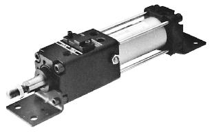
10 Sine Rodless Cylinder Series RE asic Type/ø, ø, ø, ø, ø3 asic type Sine rodless cylinder (basic type) Specifications Fluid Proof pressure Maximum operating pressure Minimum operating pressure mbient and fluid temperature Piston speed Lubrication Stroke length tolerance How to Order RE 0 ore size mm mm mm mm 3 3mm Stroke Refer to the standard stroke table. ir 1.0MPa 0.MPa 0.1MPa to 0 C (with no freezing) to 0mm/s Non-lube to 0st:, 1 to 00st: 0, 01st and up: Max. Speed 0 mm/s asic Type RE Direct Mount Type RER Slider Type/Slide earing RES Slider Type/all ushing REL High Precision Guide Type REH Standard Strokes Max. Speed 00 mm/s Symbol ore size 3 Standard stroke 0, 0, 0, 3, 0, 4, 0, 00, 00, 00 0, 0, 0, 3, 0, 4, 0, 00, 00, 00 0, 0, 0, 3, 0, 4, 0, 00, 00, 00, 00, 00 0, 0, 0, 3, 0, 4, 0, 00, 00, 00, 00, 00 0, 0, 0, 3, 0, 4, 0, 00, 00, 00, 00, 00 Note 1) Intermediate strokes can be arranged in 1mm increments. Note 2) Strokes over 00mm are available as order made. (Refer to -X on page ) Magnetic Holding Force ore size Holding force Weights 33 ore size asic weight dditional weight per mm stroke Calculation example: RE Maximum manufacturable stroke 1, asic weight kg dditional weight /mm x 0 = 2.04kg } Cylinder stroke... 0mm (N) 3 2,20 (kg) Direct Mount Type High Precision Guide Type RER REH uto Switches Order Made 1
11 Series RE Specific Product Precautions e sure to read before handling. Refer to pages 2 through 4 for safety instructions and actuator precautions. Caution Mounting 1. Take care to avoid nicks or other damage on the outside surface of the cylinder tube. This can lead to damage of the scraper and wear ring, which in turn can cause malfunction. 2. Pay attention to the rotation of the external slider. Rotation should be controlled by connecting it to another shaft (linear guide, etc.). 3. Do not operate with the magnetic coupling out of position. In case the magnetic coupling is out of position, push the external slider back into the correct position by hand at the end of the stroke (or correct the piston slider with air pressure). 4. e sure that both head covers are secured to the mounting surface before operating the cylinder. void operation with the external slider secured to the surface.. Do not apply a lateral load to the external slider. When a load is mounted directly to the cylinder, variations in the alignment of each shaft center cannot be offset, and this results in the generation of a lateral load that can cause malfunction. The cylinder should be operated using a connection method which allows for shaft alignment variations and deflection due to the cylinder's own weight. drawing of a recommended mounting is shown in Figure 2. Guide rod Rodless cylinder Variations in the load and cylinder shaft alignment cannot be offset and may result in a malfunction. Figure 1. Incorrect mounting Direct connection with bolts, etc. Shaft alignment variations are offset by providing clearance between the mounting bracket and cylinder. Moreover, the mounting bracket is extended above the cylinder shaft center, so that the cylinder is not subjected to moment. Figure 2. Recommended mounting. Use caution regarding the allowable load weight when operating in a vertical direction. The allowable load weight when operating in a vertical direction (reference values on page is determined by the model selection method. However, if a load greater than the allowable value is applied, the magnetic coupling may break and there is a possibility of dropping the load. When using this type of application, contact SMC regarding the operating conditions (pressure, load, speed, stroke, frequency, etc.). Caution Disassembly & Maintenance 1. When reattaching the head covers after disassembly, confirm that they are tightened securely. When disassembling, hold the wrench flats of one head cover with a vise, and remove the other cover using a spanner or adjustable wrench on the wrench flats. When retightening, first coat with Loctite (No. 42 red), and retighten 3 to past the original position prior to removal. 1. This mechanism is not intended for adjustment of the cushion effect (smooth start-up, soft stop). This mechanism is for matching of the cylinder's stroke end position to the mechanical stopper, etc., of a machine. (adjustment range from 0 to -2mm) 2. efore adjustment is performed, shut off the drive air, release any residual pressure and implement measures to prevent dropping of work pieces, etc. (To ensure safety, implement with air shut down.) 1. Loosen lock nut. 2. Insert a wrench into the hexagon socket of the adjustment screw, and turn it to the left or right, matching the cushion ring holder (stroke end) with the position of the external stopper by moving it backward or forward. 3. fter the stroke end adjustment is completed, retighten lock nut, and apply high strength Loctite No. 22 or another comparable locking agent. djustment screw hexagon socket RE RE RE RE RE3 Caution Caution ackward Note) Forward Stroke End djustment Width across flats Wrench Stroke djustment djustment screw Lock nut fastening torque RE RE RE RE RE3 Lock nut Fastening torque (N m) Cushion ring holder ackward Forward Note) Do not move it backward, as it is set to a full stroke at the time of shipment. 2
12 Fn: llowable driving force (N) Pv: Maximum operating pressure for vertical operation (MPa) Wmax: Maximum connection fitting weight (kg) Wv: llowable load weight for vertical operation (kg) W Guide W llowable driving force (Fn) (n = 1, 2, 3) Horizontal Inclined Vertical Series RE Selection 1 Fn F1 = μ x (W + W) x. F2 = (W + W) x. x (μcosθ + sinθ) F3 = (W + W) x. x (μ + 1) Refer to the allowable driving force table for (Fn) of data. Lo θ θ Inclined operation Horizontal operation First tentative bore size determination F1 ød 1. x P W: Load weight (kg) W: Connection fitting weight (kg) μ: Guide's coefficient of friction Operating conditions Mode of operation Inclined operation First tentative bore size determination F2 ød 1. x P Determination of connection fitting weight (W) Third tentative determination of bore size using the graph of maximum speed (U) and load weight (W). P: Operating pressure (MPa) U: Maximum speed (mm/s) Stroke L0: Distance from cylinder shaft center to work piece point of application (cm) Mode of operation (horizontal, inclined, vertical) W > WMX Review of connection fitting Vertical operation First tentative bore size determination F3 ød 1. x P W + W WV W + W > WV P PV Determination P > PV of allowable load weight & (Refer to page for pressure connection fitting weight.) W Wmax (Refer to page 4 for data.) Second tentative determination of bore size using the graph of allowable driving force (Fn) and distance from cylinder shaft center (Lo) (Refer to page 4 for data.) Review of load weight and operating pressure (Refer to page for vertical operation.) Max. Speed 0 mm/s asic Type RE Direct Mount Type RER Slider Type/Slide earing RES Slider Type/all ushing REL High Precision Guide Type REH Max. Speed 00 mm/s Direct Mount Type High Precision Guide Type RER REH ore size determination Review of order made products based on operating conditions determination Note 1) (Refer to pages through 1.) ore size is the largest of ( 3 tentative determinations. ) Note 1) Depending on the operating environment, etc., order made products should also be reviewed. uto Switches Order Made 3
13 Series RE Selection 2 Selection Method Design Parameters 1 <Data : Distance from cylinder shaft center llowable driving capacity> ø ø Recommended driving force Fn (N) Usable range Recommended driving force Fn (N) Usable range ø Recommended driving force Fn (N) Usable range ø Distance from cylinder shaft center L0 (cm) ø3 Distance from cylinder shaft center L0 (cm) Distance from cylinder shaft center L0 (cm) Recommended driving force Fn (N) Usable range Recommended driving force Fn (N) Usable range Distance from cylinder shaft center L0 (cm) Distance from cylinder shaft center L0 (cm) <Data : Maximum speed Load weight chart > Load weight W (kg) 0 0 RE3 RE RE RE RE Maximum speed U mm/s 4
14 Cylinder Self Weight Deflection Maximum self weight deflection Series RE Selection 3 When the cylinder is mounted horizontally, deflection appears due to its own weight as shown in the data, and the longer the stroke the greater the amount of variation in the shaft centers. Load platform Guide shaft RE, 3 RE RE, Stroke Max. Connection Fitting Weight The RE (basic type) is not directly connected to the load, and is guided by another shaft (LM guide, etc.). Load connection fittings should be designed so that they do not exceed the weights given in the table below. Maximum connection fitting weight Wmax (kg) Maximum load (kg) RE 1.2 RE 1. RE 2.0 RE 2. RE3 3.0 Consult with SMC if weights greater than the above will be connected. RE Clearance (0.2 to 0.mm) RE RE C The clearance C is determined by considering the cylinder's self weight deflection and the amount of discrepancy with respect to the other shaft. Normal value: (self weight deflection) +1. to 2mm RE The above deflection data indicate values for external movement within the stroke. RE3 Vertical Operation Design Parameters 2 The load should be guided by a ball type bearing (LM guide, etc.). If a slide bearing is used, sliding resistance increases due to the load weight and load moment, which can cause malfunction. W Sine rodless cylinder (RE) llowable load weight Wv (kg) Load weight (Slider bracket weight + work piece weight) Work piece Maximum operating pressure Pv (MPa) RE RE RE RE RE Note) Use caution, as operation above the maximum operating pressure may result in dislocation of the piston. Intermediate Stops The cushion effect (smooth start-up, soft stop) exists only before the stroke end in the stroke ranges indicated in the table below. The cushion effect (smooth start-up, soft stop) cannot be obtained in an intermediate stop or a return from an intermediate stop using an external stopper, etc. Cushion stroke RE RE RE RE RE3 Stroke 3 Max. Speed 0 mm/s asic Type RE Direct Mount Type RER Slider Type/Slide earing RES Slider Type/all ushing REL High Precision Guide Type REH Max. Speed 00 mm/s Direct Mount Type High Precision Guide Type RER REH uto Switches Order Made
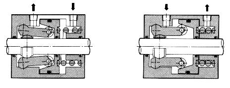
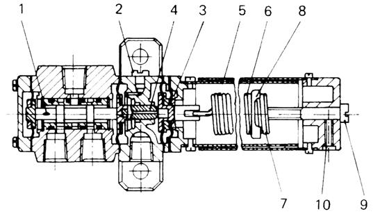
15 Series RE Construction!!!2 o!1 q y r!4 e! w!!3 i!0 t! u Parts list No Description ody Head cover Cushion ring holder Cylinder tube Piston Shaft Lock nut Piston side yoke External slider side yoke Magnet Material luminum alloy luminum alloy luminum alloy Stainless steel luminum alloy Stainless steel Carbon steel Rolled steel Rolled steel Rare earth magnet Note nodized nodized Chromated Chromated Nickel plated Zinc chromated Zinc chromated No Description Magnet umper Cushion seal holder Cushion ring djustment screw Stopper bolt Lock nut Snap ring Spring washer Material Rare earth magnet Urethane rubber luminum alloy rass Carbon steel Carbon steel Carbon steel Carbon tool steel Steel wire Note Chromated Electroless nickel plated Nickel plated Nickel plated Nickel plated Start-up cceleration Deceleration Stop Operating Principle Start-up/cceleration The driving air from the cylinder port passes through the inside of the cushion ring, and flows into the left chamber of the drive piston from the clearance between the cushion seal and the U-shaped groove in the outer surface of the cushion ring. Further, the exhaust air in the right chamber of the drive piston passes from inside the hollow cushion ring through the cylinder port and is released to the atmosphere by the drive solenoid valve. When the differential pressure (thrust) generated on either side of the drive piston becomes larger than the starting resistance of the machinery, the drive piston begins to move to the right. s the drive piston moves to the right, the U-shaped groove in the outer surface of the cushion ring gradually becomes deeper, a flow corresponding to the drive speed of the drive piston flows into the left chamber of the drive piston, and the drive piston proceeds to accelerate. The U-shaped groove is machined into the cushion ring in such a way that this acceleration process can proceed smoothly (as a sine function). Deceleration/Stop In conventional cushion mechanisms, when the cushion seal installed on the drive piston is pushed into the cushion ring at the right stroke end, the drive piston's right chamber is pressurized and a sudden braking force is generated. However, in a sine rodless cylinder, due to the U-shaped groove provided on the outer surface of the cushion ring, whose depth changes as a sine function, a large quantity of the air in the cushion chamber is discharged when the cushion seal is pushed in, and a sudden braking force is not generated. With the progression of the cushion stroke, the discharge flow from the cushion chamber is restricted, and therefore, a soft stop is achieved at the stroke end.
16 Dimensions Sine Rodless Cylinder asic Type Series RE Max. Speed 0 mm/s RE,, H G L MM Effective thread depth J 2- Port size G NN asic Type RE X D øi Direct Mount Type RER RE RE RE RE RE RE RE, 3 T N S Port size Rc 1/ Rc 1/ Rc 1/4 N W 0 X ZZ 13 F R D R N N K W F 13 T G 33 H I 34 K S + Stroke ZZ + Stroke L L MM x J M x 0. x M x 1.0 x M x 1.0 x N 1 21 N N F N N Rc 1/4 NN M2 x 1. M2 x 1. M x 2.0 Slider Type/Slide earing RES Slider Type/all ushing REL High Precision Guide Type REH Max. Speed 00 mm/s RE RE3 22 C 0 ± 0.1 C 3 D 3 E(h) I K 2 N Mounting nuts: 2pcs. packaged with each cylinder H d øi øe(h) -Q Effective thread depth R. C 23 K W 2 S + Stroke Part No. SN-0 SN-0 L 1 2 X Q x R M x 1. x M x 1. x pplicable bore size ø, ø ø ZZ + Stroke S 1 1 d M2 x 1. M x TC Effective thread depth R 4 -M x 1. Effective thread depth TC x R M x 1. x. M x 1. x. H ød 41 C W X 0 0 øe(h) 2 ZZ Direct Mount Type High Precision Guide Type RER REH uto Switches Order Made
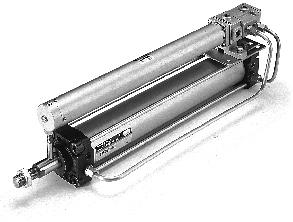
17 Sine Rodless Cylinder Series RER Direct Mount Type ø, ø, ø, ø, ø, ø How to Order RE R 0 Z3 Sine rodless cylinder Direct mount type ore size mm mm mm mm mm mm Standard stroke Refer to the standard stroke table on page. Switch rails Nil N Number of auto switches Nil 2 pcs. S 1 pc. n "n" pcs. uto switch type Nil Without auto switch Note 1) In case of ø with switch rail but without switches, the cylinder configuration is for reed switches. Refer to the table below for auto switch part numbers. With switch rails Without switch rails Note 1) When equipped with switch rails, magnets for switches are built in. Note 2) In case of ø, magnets for switches are built in even when not equipped with switch rails. pplicable auto switches For ø, ø, ø Type Reed switch Solid state switch Special function Electrical entry Grommet Grommet Indicator light No Yes Yes Wiring (output) 2 wire 3 wire (NPN equiv.) 3 wire (NPN) 3 wire (PNP) 2 wire Note 1) Lead wire length symbol 0.m... Nil (Example) FN 3m... L FNL For ø, ø, ø Type Reed switch Solid state switch Special function Diagnostic indication (2 color indicator) Electrical entry Grommet Grommet Refer to "uto Switch Guide" (E24-) for further details on auto switch units. Refer to pages 4 and for auto switch circuit diagrams. Indicator light Yes No Yes Wiring (output) 3 wire 2 wire 3 wire (NPN) 3 wire (PNP) 2 wire 3 wire (NPN) 3 wire (PNP) 2 wire 24V DC DC Load voltage C, V 0V or less 0V C V V 0V, V 0V or less Note 1) Lead wire length symbol 0.m... Nil (Example) Y 3m... L YL m... Z YZ Note 2) Solid state auto switches marked with a "" are produced upon receipt of order. 24V 24V 24V V V V Load voltage, V V, V V uto switch model 0 3 FN FP F uto switch model Z Z3 Z0 Y YP Y YNW YPW YW Note 1) Lead wire length (m) 0. (Nil) 0. (Nil) 3 (L) 3 (L) (Z) Note 1) Lead wire length (m) (Z) pplicable load IC circuit Relay, PLC IC circuit IC circuit Relay, PLC Relay, PLC IC circuit IC circuit Relay, PLC IC circuit pplicable load
18 Specifications Sine Rodless Cylinder Direct Mount Type Series RER Max. Speed 0 mm/s Fluid Proof pressure Maximum operating pressure Minimum operating pressure mbient and fluid temperature Piston speed Lubrication Stroke length tolerance Mounting Standard Strokes ore size Standard stroke ir 1.0MPa 0.MPa 0.1MPa to 0 C to 0mm/s Non-lube 0 to 0st: , 1 to 00st: , 01st and up: Direct mount type Maximum manufacturable stroke Maximum stroke with switch asic Type RE Direct Mount Type RER Slider Type/Slide earing RES Weights Item asic weight (for 0st) 1, 0, 0, 0 1, 0, 0, 0, 3, 0 4, 0 0, 0, 0, 3, 0, 4 0, 00, 00, 00 0, 0, 0, 3, 0, 4 0, 00, 00, 00, 00, 00 Note) Intermediate strokes can be arranged in 1mm increments. Magnetic Holding Force ore size Holding force 3. ore size RER (with switch rail) RER-N (without switch rail) dditional weight per mm stroke (when equipped with switch rail) (N) 22 (kg) Slider Type/all ushing REL High Precision Guide Type REH Max. Speed 00 mm/s Direct Mount Type High Precision Guide Type RER REH dditional weight per mm stroke (when not equipped with switch rail) Calculation method/example: RER-0 (with switch rail) asic weight kg, dditional weight kg/mm, Cylinder stroke... 0mm x 0 = 1.4kg uto Switches Order Made
19 Series RER Specific Product Precautions e sure to read before handling. Refer to pages 2 through 4 for safety instructions and actuator precautions. Mounting Caution 1. Take care to avoid nicks or other damage on the outside surface of the cylinder tube. This can lead to damage of the scraper and wear ring, which in turn can cause malfunction. 2. Pay attention to the rotation of the external slider. Rotation should be controlled by connecting it to another shaft (linear guide, etc.). 3. Do not operate with the magnetic coupling out of position. In case the magnetic coupling is out of position, push the external slider back into the correct position by hand at the end of the stroke (or correct the piston slider with air pressure). 4. The cylinder is mounted with bolts through the mounting holes in the end covers. e sure they are tightened securely.. e sure that both end covers are secured to the mounting surface before operating the cylinder. void operation with the external slider secured to the surface.. Do not apply a lateral load to the external slider. When a load is mounted directly to the cylinder, variations in the alignment of each shaft center cannot be offset, which results in the generation of a lateral load that can cause malfunction. The cylinder should be operated using a connection method which allows for shaft alignment variations and deflection due to the cylinder's own weight. drawing of a recommended mounting is shown in Figure Special tools are necessary for disassembly. Special tool number list No. CYRZ-V CYRZ-W Disassembly & Maintenance Caution F Special tool pplicable bore size,,,, Guide rod Direct connection with bolts, etc. Guide rod Mounting bracket Clearance Rodless cylinder Variations in the load and cylinder shaft alignment cannot be offset and may result in a malfunction. Figure 1. Incorrect mounting Rodless cylinder Shaft alignment variations are offset by providing clearance between the mounting bracket and cylinder. Moreover, the mounting bracket is extended above the cylinder shaft center, so that the cylinder is not subjected to moment. Figure 2. Recommended mounting. Use caution regarding the allowable load weight when operating in a vertical direction. The allowable load weight when operating in a vertical direction (reference values on page 13) is determined by the model selection method. However, if a load greater than the allowable value is applied, the magnetic coupling may break and there is a possibility of dropping the load. When using this type of application, contact SMC regarding the operating conditions (pressure, load, speed, stroke, frequency, etc.).
20 Series RER Selection 1 Fn: llowable driving force (N) MD: Maximum allowable moment when connection fitting, etc., is directly loaded (N m) Pv: Maximum operating pressure for vertical operation (MPa) Wmax: Maximum load weight when loaded directly on the body (kg) Wv: llowable load weight for vertical operation (kg) Operating conditions W: Load weight (kg) Presence of switches W: Connection fitting weight (kg) P: Operating pressure (MPa) μ: Guide's coefficient of friction U: Maximum Speed (mm/s) L0: Distance from cylinder shaft center to work Stroke piece point of application (cm) Mode of operation L1: Distance from cylinder shaft center to (horizontal, inclined, vertical) center of gravity of connection fitting, etc. Mode of operation Max. Speed 0 mm/s asic Type RE Direct Mount Type RER Horizontal operation Inclined operation Vertical operation Review of load weight and operating pressure Slider Type/Slide earing RES W Guide W Fn Lo θ θ Inclined operation llowable driving force (Fn) (n = 1, 2, 3) Horizontal Inclined Vertical F1 = μ x (W + W) x. F2 = (W + W) x. x (μcosθ + sinθ) F3 = (W + W) x. x (μ + 1) Refer to the allowable driving force table for (Fn) of data. First tentative bore size determination F1 ød 1. x P W > Wmax Review of connection fitting W Wmax (Refer to page for data.) (Refer to page for data.) First tentative bore size determination F2 ød 1. x P Determination of connection fitting weight (W) Presence of switch rails No W + W WV P PV (See page13 for maximum load weight when loaded directly on the body.) Yes Second tentative determination of bore size using the graph of allowable driving force (Fn) and distance from cylinder shaft center (Lo) Third tentative determination of bore size using the graph of maximum speed (U) and load weight (W). First tentative bore size determination F3 ød 1. x P Review of switches and stroke Yes Determination of allowable load weight & pressure Note 2) W x L1 > MD Presence of switches Presence of external guide system Determination of rotational moment W + W > WV P > PV No No (See page13 for vertical operation.) Yes NG Determination of stroke with switches OK (See the standard stroke table on p..) (See page for body non-rotating accuracy and maximum allowable moment.) Slider Type/all ushing REL High Precision Guide Type REH Max. Speed 00 mm/s Direct Mount Type High Precision Guide Type RER REH ore size is the largest of ( ) ore size determination 3 tentative determinations. Note 1) Review of order made products based on operating conditions (Refer to pages through 1.) determination Note 2) NG Determination of allowable stroke OK W x L1 MD (See page for body non-rotating accuracy and maximum allowable moment.) Note 1) Depending on the operating environment, etc., order made products should also be reviewed. Note 2) n external guide system should be used if the specification is exceeded. uto Switches Order Made
21 Series RER Selection 2 Selection Method Design Parameters 1 <Data : Distance from cylinder shaft center llowable driving capacity> RER RER llowable driving force Fn (N) Usable range llowable driving force Fn (N) 0 0 Usable range RER llowable driving force Fn (N) Usable range RER llowable driving force Fn (N) Distance from cylinder shaft center L0 (cm) Usable range RER llowable driving force Fn (N) Distance from cylinder shaft center L0 (cm) Usable range RER llowable driving force Fn (N) Distance from cylinder shaft center L0 (cm) Usable range Distance from cylinder shaft center L0 (cm) Distance from cylinder shaft center L0 (cm) Distance from cylinder shaft center L0 (cm) <Data : Maximum speed Load weight chart > Load weight W (kg) 0 0 RER RER RER RER RER RER Maximum speed U (mm/s)
22 Cylinder Self Weight Deflection When the cylinder is mounted horizontally, deflection appears due to its own weight as shown in the data, and the longer the stroke, the greater the amount of variation in the shaft centers. Therefore, a connection method should be considered which allows for this variation as shown in the drawing. Guide shaft Series RER Selection 3 Load platform Design Parameters 2 Vertical Operation The load should be guided by a ball type bearing (LM guide, etc.). If a slide bearing is used, sliding resistance will increase due to the load weight and moment, and this can cause malfunction. Load weight (Slider bracket weight + work piece weight) Work piece Max. Load Weight when Loaded Directly on ody When the load is applied directly to the body, it should be no greater than the maximum values shown in the table below. RER RER RER RER RER RER Maximum load weight Wmax (kg) Loading direction Max. Speed 0 mm/s asic Type RE Direct Mount Type RER Slider Type/Slide earing RES C Note) Clearance Note) (0.2 to 0.mm) Rodless cylinder W Loading direction Switch rail Slider Type/all ushing REL Note) Referring to the self weight deflection in the figure below, provide clearance so that the cylinder is able to operate smoothly through the full stroke within the minimum operating pressure range, without touching the mounting surface or the load, etc. RER,, RER RER RER Cylinder bore size RER RER RER RER RER RER llowable load weight Wv (kg) Max. operating pressure Pv (MPa) Note) Use caution, as operation above the maximum operating pressure can result in breaking of the magnetic coupling. ody Wear ring C High Precision Guide Type REH Max. Speed 00 mm/s Direct Mount Type RER mount of deflection RER RER RER RER RER Stroke RER High Precision Guide Type REH uto Switches The above deflection data indicate values when the external slider has moved to the middle of the stroke. Order Made 13
23 Series RER Selection 4 Design Parameters 3 Intermediate Stops The cushion effect (smooth start-up, soft stop) exists only before the stroke end in the stroke ranges indicated in the table below. The cushion effect (smooth start-up, soft stop) cannot be obtained in an intermediate stop or a return from an intermediate stop using an external stopper, etc. Cushion Stroke RER RER RER RER RER RER Stroke 3 ody Non-rotating ccuracy and Maximum llowable Moment (with Switch Rail) (Reference Values) Reference values for non-rotating accuracy and maximum allowable moment at stroke end are indicated below. ore size Non-rotating accuracy ( ) Max. allowable moment (MD) (N m) Note 2) llowable stroke Non-rotating accuracy ody Switch rail Wear ring C Note 1) void operations where rotational torque (moment) is applied. In such a case, the use of an external guide is recommended. Note 2) The above reference values will be satisfied within the allowable stroke ranges. However, caution is necessary because as the stroke becomes longer the inclination (rotation angle) within the stroke can be expected to increase. Note 3) When a load is applied directly to the body, the loaded weight should be no greater than the allowable load weights on page 13.
24 Construction/ø, ø Sine Rodless Cylinder Direct Mount Type Series RER Max. Speed 0 mm/s asic Type RE Direct Mount Type RER Slider Type/Slide earing RES Slider Type/all ushing REL Parts list No. Description 1 ody 2 Cylinder tube 3 Shaft 4 Piston side yoke External slider side yoke Magnet Magnet Piston Spacer Snap ring Cushion ring End cover 13 End cover ttachment ring 1 C type snap ring for shaft Hexagon socket head set screw Cylinder tube gasket Material Note luminum alloy Hard anodized Stainless steel Stainless steel Rolled steel plate Zinc chromated Rolled steel plate Zinc chromated Rare earth magnet Rare earth magnet rass Electroless nickel plated Rolled steel plate Nickel plated Carbon tool steel Nickel plated Stainless steel luminum alloy Hard anodized luminum alloy Hard anodized luminum alloy Hard anodized Stainless steel RER Hard steel wire Nickel plated (RER) Chromium steel NR Switch Rail ccessory Kits CYR ore size E Stroke Nickel plated RER Parts list No. Description 1 Wear ring 1 Wear ring Piston seal 21 Scraper 22 Cushion seal 23 Magnetic shielding plate 24 Switch rail Magnet 2 Hexagon socket head screw 2 Wear ring C Replacement parts: Seal kits ore size Order no. RER-PS RER-PS Switch rail accessory kits ore size Kit no. CYRE- CYRE- Note 1) indicates the stroke. Note 2) ø has internal magnets in the body. Material Special resin Special resin NR NR NR Rolled steel plate luminum alloy Rare earth magnet Chromium steel Special resin Note Chromated Clear anodized Nickel plated Seal kits are sets consisting of numbers 1 through 22 above, and can be ordered using the order number for each bore size. Content bove numbers 1, 1, 1,, 21, 22, 2 Content bove numbers 24,, 2, 2 bove numbers 23, 24, 2, 2 Note 2) High Precision Guide Type REH Max. Speed 00 mm/s Direct Mount Type High Precision Guide Type RER REH uto Switches Order Made
25 Series RER Construction/ø to ø y Parts list Parts list No. Description Material Note No. Description Material Note ody Cylinder tube Shaft Piston side yoke External slider side yoke luminum alloy Stainless steel Stainless steel Rolled steel plate Rolled steel plate Hard anodized Zinc chromated Zinc chromated Wear ring Wear ring Piston seal Scraper Cushion seal Special resin Special resin NR NR NR Magnet Magnet umper Cushion seal holder Piston Rare earth magnet Rare earth magnet Urethane rubber luminum alloy luminum alloy Chromated Chromated Magnetic shielding plate Switch rail Magnet Hexagon socket head screw Wear ring C Rolled steel plate luminum alloy Rare earth magnet Chromium steel Special resin Chromated Clear anodized Nickel plated Spacer Snap ring Rolled steel plate Carbon tool steel Nickel plated Nickel plated Seal kits are sets consisting of numbers through and above, and can be ordered using the kit number for each bore size. Electroless nickel plated rass 13 Cushion ring (RER, ) Lock nut Stainless steel Carbon steel RER, Nickel plated End cover luminum alloy Hard anodized End cover luminum alloy Hard anodized Replacement parts: Seal kits 1 ttachment ring luminum alloy Hard anodized ore size Kit no. Content Stainless steel RER, 1 C type snap ring for shaft RER-PS Hard steel wire Nickel plated (RER, ) Hexagon socket RER-PS bove numbers 1 head set screw Chromium steel Nickel plated RER-PS, 21, 22, 23, 24,, Cylinder tube gasket NR RER-PS Switch Rail ccessory Kits CYR E ore size Stroke Switch rail accessory kits ore size Kit no. For reed switch CYRE- For solid state CYREN- CYRE- CYRE- CYRE- Note 1) indicates the stroke. Content bove numbers 2, 2, 2, 2,
26 Dimensions Sine Rodless Cylinder Direct Mount Type Series RER Max. Speed 0 mm/s HC HT W K X asic Type RE RER C 4-J effective thread length E RER HS CR H H HR 2-P piping port 4-øLD GW GP Plug WS T Y L W K Q + Stroke Z + Stroke N -MM thread depth M X F ød Switch rail 4-Counter bore ø Counter bore depth C T QW PW G Direct Mount Type RER Slider Type/Slide earing RES Slider Type/all ushing REL RER RER RER RER RER RER RER RER RER RER RER RER... K L C LD C M 4 CR D MM M3 x 0. M4 x 0. M4 x 0. M x 0. M x 1 M x 1 F N 4... G GP P M x 0. M x 0. Rc 1/ Rc 1/ Rc 1/ Rc 1/4 GW PW H Q H QW HC T HR W 0 HS... WS HT X J x E M4 x 0. x M x 0. x M x 1 x M x 1 x M x 1. x M x 1. x Y Z High Precision Guide Type REH Max. Speed 00 mm/s Direct Mount Type High Precision Guide Type RER REH uto Switches Order Made 1
27 Series RER Proper uto Switch Mounting Position for Stroke End Detection ø to ø C uto switch C D ore model size D- D-F D- D-F D- D-F D- D-F Note) uto switches cannot be installed in rea C in the case of ø. D uto Switch Operation Range ore size uto switch model D- D-F D-Z D-Z 13 4 D-Y D-Y D-YW Note 1) Switches cannot be mounted in some cases. Note 2) Operating ranges are standards including hysteresis, and are not guaranteed. Large variations may occur depending on the surrounding environment (variations on the order of ±%). ø to ø uto switch model ore size D-Z D-Z D-Y D-Y D-YW D-Z D-Z. 4. C D D-Y D-Z D-Y D-Z D-Y D-Z D-Y D-Z D-YW D-YW D-Y D-Y D-YW uto Switch Mounting When mounting auto switches, they should be inserted into the cylinder's switch groove from the direction shown in the drawing on the right. fter setting in the mounting position, use a flat head watchmakers screw driver to tighten the mounting screw which is included. Note) When tightening the auto switch mounting screw, use a watchmakers screw driver with a handle about to mm in diameter. Furthermore, the tightening torque should be approximately 0.0 to 0.1N m. s a rule, it can be turned about 0 past the point at which tightening can be felt. Flat head watchmakers screw driver uto Switch Specifications ø to ø Switch mounting screw (M2. x 4l) (included) uto switch (1) Switches (switch rail) can be added to the standard type (without switch rail). Switch rail accessory kits are mentioned on pages and and can be ordered together with auto switches. (2) Refer to the separate disassembly instructions for switch magnet installation procedures. 1
28 Sine Rodless Cylinder Series RES Slider Type/Slide earing How to Order RE S 0 2 Max. Speed 0 mm/s asic Type RE Direct Mount Type RER Type Reed switches Solid state switches Sine rodless cylinder pplicable auto switches Special function Diagnostic indication (2 color indicator) Water resistant (2 color indicator) With timer With diagnostic output (2 color indicator) Latch type with diagnostic output (2 color indicator) Slider type (slide bearing) Electrical entry Connector ore size mm mm mm mm mm mm Refer to "uto Switch Guide" (E-24-) for further details on auto switch units. Refer to pages 4 and for auto switch circuit diagrams. Grommet Grommet Connector Grommet Indicator light Yes No Yes No Yes Wiring (output) 3 wire (NPN equiv.) Note 1) Lead wire length symbol 0.m... Nil (Example) 0C 3m... L (Example) 0CL m... Z (Example) 0CZ None... N (Example) 0CN Note 2) Solid state auto switches marked with a "" are produced upon receipt of order. Note 3) Type D-FLF cannot be mounted on bore size ø. Standard stroke Refer to the standard stroke table on page. DC Load voltage V C Number of auto switches Nil 2 pcs. S 1 pc. n "n" pcs. uto switch model Electrical entry direction Perpendicular In-line 0V 2 V 0V 3 2 wire V, V 0V or less 0 24V V 3C V, V 24V or less 0C 3 wire (NPN) FNV 3 wire (PNP) V, V FPV 2 wire V FV JC 3 wire (NPN) FNWV V, V 3 wire (PNP) 24V FWV 2 wire V 3 wire (NPN) V, V 4 wire (NPN) uto switch type Nil Without auto switch Refer to the table below for applicable auto switch models. In cases without auto switches, there are switch rails only. 0. (Nil) 3 (L) (Z) None (N) H IC circuit 2H 3H 0H IC circuit IC circuit F IC circuit FP J FW IC circuit FPW JW F FNT FF IC circuit Note 3) Note 1) Lead wire length (m) FLF pplicable load Relay, PLC Relay, PLC Slider Type/Slide earing RES Slider Type/all ushing REL High Precision Guide Type REH Max. Speed 00 mm/s Direct Mount Type High Precision Guide Type RER REH uto Switches Order Made 1
29 Series RES Specifications Fluid Proof pressure Maximum operating pressure Minimum operating pressure mbient and fluid temperature Piston speed Lubrication Stroke length tolerance ir 1.0MPa 0.MPa 0.1MPa to 0 C to 0mm/s Non-lube 0 to 0st: , 1 to 00st: , 01st and up: Standard Strokes ore size Standard stroke 1, 0, 0, 0 1, 0, 0, 0, 3, 0 4, 0 0, 0, 0, 3, 0, 4 0, 00, 00, 00 0, 0, 0, 3, 0, 4 0, 00, 00, 00, 00, 00 Note) Intermediate strokes can be arranged in 1mm increments. Maximum manufacturable stroke Magnetic Holding Force (N) ore size Holding force Weights ore size asic weight dditional weight per mm stroke Calculation method/example: RES-0 asic weight kg dditional weight /mm Cylinder stroke... 0mm x 0 =.3kg (kg)
30 Sine Rodless Cylinder Slider Type/Slide earing Series RES Max. Speed 0 mm/s Specific Product Precautions e sure to read before handling. Refer to pages 2 through 4 for safety instructions and actuator precautions. asic Type RE Warning Operation 1. e aware of the space between the plates and the slide block. Take sufficient care as fingers and hands, etc., may be injured if caught while the cylinder is in operation. 2. Do not apply a load to a cylinder, which is greater than the allowable value stated in the "model selection pages". Mounting Caution 1. void operation with the external slider fixed to the mounting surface. The cylinder should be operated with the plates fixed to the mounting surface. 2. Perform mounting so that the external slider will operate through the entire stroke at the minimum operating pressure. If the mounting surface is not flat, the guides will be warped, increasing the minimum operating pressure and causing premature wear of the bearings. Therefore, mounting should be performed so that the external slider will operate through the entire stroke at the minimum operating pressure. mounting surface with a high degree of flatness is desirable, but in cases where this is not possible, adjust with shims, etc. Direct Mount Type RER Slider Type/Slide earing RES Slider Type/all ushing REL High Precision Guide Type REH Max. Speed 00 mm/s Direct Mount Type High Precision Guide Type RER REH uto Switches Order Made 21
31 Series RES Selection 1 Pv: Maximum operating pressure for vertical operation (MPa) W: llowable load weight based on these operating conditions (kg) Wv: llowable load weight for vertical operation (kg) σ: Stroke coefficient Load weight within stroke σ = Max. load weight Operating conditions W: Load weight (kg) U: Maximum speed (mm/s) P: Operating pressure (MPa) Stroke L0: Distance from slide block mounting surface to work piece center of gravity (cm) Mode of operation (horizontal, inclined, vertical) Mode of operation Horizontal operation Inclined operation Vertical operation Review of load weight and operating pressure First tentative bore size determination W ød 2. x P First tentative bore size determination 0.3 x Wcosθ + Wsinθ ød.0 x P First tentative bore size determination 0.3 x W + W ød.0 x P W θ θ Inclined operation Determination of allowable load weight & pressure W Wv P Pv W > Wv P > Pv (Refer to page for vertical operation.) (Refer to page 23 for formulas to find σ.) Calculate stroke coefficient (σ) with stroke and tentatively determined bore size Load weight in stroke σ = Maximum load weight Select an example calculation for allowable weight based on cylinder mounting orientation (Refer to pages 23 and 24.) Review of bore size, stroke and L0 W > W Calculate (W) from the formula for the tentatively determined bore size (Refer to Data on page 23.) W W The larger bore size is selected ( from two tentative determinations. ) Second tentative determination of bore size from graph of maximum speed (U) and load weight (W) ore size determination Note 1) Depending on the operating environment, etc., order made products should also be reviewed. Note 1) Review of order made products based on operating conditions (Refer to pages through 1.) determination 22
32 How to Find σ when Selecting the llowable Load Weight Since the maximum load weight with respect to the cylinder stroke changes as shown in the table below, σ should be considered as a coefficient determined in accordance with each stroke. Example) for RES (1) Maximum load weight = kg (2) Load weight for st = 13.kg 13. (3) σ = = 0. is the result. Design Parameters 1 Examples of llowable Load Weight Calculation ased on Cylinder Mounting Orientation 1. Horizontal operation (floor mounting) Calculation formula for σ (σ 1) ST: Stroke Maximum load weight (center of slide block) (kg) σ= Series RES Selection 2 RES ( x 3 x ST) 3 RES ( x 3 x ST) RES ( x 3 x ST) σ= Note) Calculate with σ = 1 for all applications up to ø0mmst, ø0mmst, ø0mmst, ø0mmst, ø00mmst and ø00mmst. RES ( x 3 x ST) RES (1..3 x 3 x ST) RES ( x 3 x ST) ore size Max. load weight (kg) Stroke (max) 3 to 0st 2. Horizontal operation (wall mounting) to 0st to 0st to 0st to 00st to 00st The above maximum load weight values will change with the stroke length for each cylinder size, due to limitation from warping of the guide shafts. (Take note of the coefficient σ.) Moreover, depending on the operating direction, the allowable load weight may be different from the maximum load weight. Max. Speed 0 mm/s asic Type RE Direct Mount Type RER Slider Type/Slide earing RES Slider Type/all ushing REL Load weight (kg) (13.) () Cylinder stroke <Data : Maximum speed Load weight chart> Load weight W (kg) RES RES RES RES RES RES RES RES RES RES RES RES 0 0 Maximum speed U (mm/s) 0 Lo: Distance from mounting surface to load center of gravity (cm) 3. Vertical operation ore size ore size Lo: Distance from mounting surface to load center of gravity (cm) Note) safety factor should be considered to prevent dropping. llowable load weight W (kg) σ Lo σ Lo σ Lo σ Lo σ 1 + 2Lo σ. + 2Lo llowable load weight W (kg) σ Lo σ Lo σ Lo σ Lo σ Lo σ..1 + Lo High Precision Guide Type REH Max. Speed 00 mm/s Direct Mount Type High Precision Guide Type RER REH uto Switches Order Made 23
: k = [to 4 (= θ)] = 1, [to 0 ] = 0., [to ] = 0., [to 0 ] = 0. Lo: Distance from mounting surface to load center of gravity (cm).")
33 Series RES Selection 3 Design Parameters 2 Examples of llowable Load Weight Calculation ased on Cylinder Mounting Orientation 4. Inclined operation (in operating direction) ngle k to 4 1 to 0 0. to 0. to 0 0. ore size ngle coefficient (k): k = [to 4 (= θ)] = 1, [to 0 ] = 0., [to ] = 0., [to 0 ] = 0. Lo: Distance from mounting surface to load center of gravity (cm). Inclined operation (at a right angle to operating direction) llowable load weight W (kg) σ. K 3.cos θ + 2 (2.2 + Lo) sin θ σ 3 K cos θ + 2 (2. + Lo) sin θ σ 2 K cos θ +2 (2. + Lo) sin θ σ 1 K cos θ + 2 (3.4 + Lo) sin θ σ 2 K cos θ + 2 (4.2 + Lo) sin θ σ 0 K cos θ + 2 (.1 + Lo) sin θ. Horizontal operation (pushing load, pusher) F: Drive (from slide block to position Lo) resistance force (kg) Lo: Distance from mounting surface to load center of gravity (cm) ore size llowable load weight W (kg) ore size llowable load weight W (kg) σ Lo σ L o σ Lo σ L o σ Lo σ Lo. Horizontal operation (load, lateral offset Lo) Lo: Distance from mounting surface to load center of gravity (cm) ore size. Load center offset in operating direction (Lo) llowable load weight W (kg) σ (2.2 + Lo) sin θ σ (2. + Lo) sin θ σ (2. + Lo) sin θ σ (3.4 + Lo) sin θ σ. + 2 (4.2 + Lo) sin θ σ (.1 + Lo) sin θ Lo: Distance from mounting surface to load center of gravity (cm) ore size llowable load weight W (kg) ore size llowable load weight W (kg) σ. 4 + Lo σ.0 + Lo σ Lo σ Lo σ Lo σ Lo Lo: Distance from slide block center to load center of gravity (cm) 24 ore size llowable load weight W (kg) σ. Lo + 3. σ 1. Lo +.0 σ 3 Lo +.0 σ 0 Lo +.0 σ Lo +.0 σ 0 Lo +.0
34 Vertical Operation Series RES Selection 4 Design Parameters 3 Intermediate Stops Max. Speed 0 mm/s asic Type RE When operating a load vertically, it should be operated within the allowable load weights and maximum operating pressures shown in the table below. Use caution, as operating above the prescribed values may lead to dropping of the load. ore size RES RES RES RES RES RES Stroke djustment llowable load weight Wv (kg) Max. operating pressure Pv (MPa) Note) Use caution, as there is a possibility of breaking the magnetic coupling if operated above the maximum operating pressure. The adjustment bolt is adjusted to the optimum position for smooth acceleration and deceleration at the time of shipment, and should be operated at the full stroke. When stroke adjustment is necessary, the maximum amount of adjustment on one side is 2mm. (Do not adjust more than 2mm, as it will not be possible to obtain smooth acceleration and deceleration.) Stroke djustment Loosen the hexagon nut, and after performing the stroke adjustment from the plate side with a hexagon wrench, retighten and secure the hexagon nut. The cushion effect (smooth start-up, soft stop) exists only before the stroke end in the stroke ranges indicated in the table below. The cushion effect (smooth start-up, soft stop) cannot be obtained in an intermediate stop or a return from an intermediate stop using an external stopper, etc. Cushion stroke RES RES RES RES RES RES Stroke 3 Direct Mount Type RER Slider Type/Slide earing RES Slider Type/all ushing REL High Precision Guide Type REH Max. Speed 00 mm/s mount of stroke adjustment (max. 2mm) T djustment bolt Direct Mount Type RER Plate Hexagon nut djustment olt Position (at Shipment), Hexagon Nut Tightening Torque High Precision Guide Type REH RES RES RES RES RES RES T Tightening torque (N m) uto Switches Order Made
35 Series RES Construction/ø, y u w e t r!2!3 @0 RES Parts list No Description Cylinder tube External slider tube Shaft Piston side yoke External slider side yoke Magnet Magnet Cushion seal holder Piston Slide block Spacer Slider spacer Snap ring ushing Cushion ring Plate Material Stainless steel luminum alloy Stainless steel Rolled steel plate Rolled steel plate Rare earth magnet Rare earth magnet luminum alloy rass luminum alloy Rolled steel plate Rolled steel plate Carbon tool steel Oil retaining bearing material Stainless steel luminum alloy Note Zinc chromated Zinc chromated nodized Electroless nickel plated Hard anodized Nickel plated Nickel plated Nickel plated Hard anodized Replacement parts: Seal kits ore size Kit no. RES-PS RES-PS Contents bove numbers 2, 2, 2, 2,, 31, Parts list No. Description 1 Plate 1 Port cover 1 Guide shaft Guide shaft djustment bolt djustment bolt Hexagon nut Switch mounting rail uto switch Cylinder tube gasket Guide shaft gasket Wear ring Wear ring Piston seal Scraper Cushion seal Material luminum alloy luminum alloy Carbon steel Carbon steel Chromium molybdenum steel Chromium molybdenum steel Carbon steel luminum alloy NR NR Special resin Special resin NR NR NR Note Hard anodized Hard anodized Hard chrome plated Hard chrome plated Nickel plated Nickel plated Nickel plated Seal kits are sets consisting of items 2 through above, and can be ordered using the kit number for each bore size. 2
36 Construction/ø to ø Sine Rodless Cylinder Slider Type/Slide earing Series RES Max. Speed asic Type RE Direct Mount rt e w u y!3!4 i o q!!!! Slider Type/Slide earing RES Slider Type/all ushing REL Parts list No Description Cylinder tube External slider tube Shaft Piston side yoke External slider side yoke Magnet Magnet umper Cushion seal holder Piston Slide block Spacer Slider spacer Snap ring ushing Cushion ring holder Cushion ring Replacement parts: Seal kits ore size Kit no. RES-PS RES-PS RES-PS #2 #0 #1 #3 #4 Material Stainless steel luminum alloy Stainless steel Rolled steel plate Rolled steel plate Rare earth magnet Rare earth magnet Urethane rubber luminum alloy luminum alloy luminum alloy Rolled steel plate Rolled steel plate Carbon tool steel Oil retaining bearing material luminum alloy rass Stainless steel Note Zinc chromated Zinc chromated Chromated Chromated Hard anodized Nickel plated Nickel plated Nickel plated nodized Electroless nickel plated (RES, ) RES, Contents bove numbers 2, 2,, 31,, 33, 34 Parts list No. Description 1 Lock nut 1 Plate Plate 21 Guide shaft 22 Guide shaft 23 djustment bolt djustment bolt Hexagon nut Switch mounting rail uto switch Cylinder tube gasket Guide shaft gasket Wear ring Wear ring Piston seal Scraper Cushion seal Material Carbon steel luminum alloy luminum alloy Carbon steel Carbon steel Chromium molybdenum steel Chromium molybdenum steel Carbon steel luminum alloy NR NR Special resin Special resin NR NR NR Note Nickel plated Hard anodized Hard anodized Hard chrome plated Hard chrome plated Nickel plated Nickel plated Nickel plated When equipped with auto switch Seal kits are sets consisting of items 2 through 34 above, and can be ordered using the kit number for each bore size. High Precision Guide Type REH Max. Speed 00 mm/s Direct Mount Type High Precision Guide Type RER REH uto Switches Order Made 2
37 Series RES Dimensions/ø M4 x 0. thread depth. 4 + Stroke. 3 2 Hollow shaft for piping 2-M x ø ø ø 1 ø M x 0. Thread depth. uto switch mounting rail can also be installed on opposite side M x Stroke uto switch Stroke pprox. 2
38 Dimensions/ø to ø Sine Rodless Cylinder Slider Type/Slide earing Series RES Max. Speed 0 mm/s asic Type RE F E tb 2 Counter bore dia. ø Counter bore depth C TT P S + Stroke Hollow shaft for piping MM thread depth M T 2-P ta HG F E ta Port cover ø34 3 F E Direct Mount Type RER 4-J x K (depth) 4-øLD QW P W ød ød HT GP PW 2-P HT HG GP PW Slider Type/Slide earing RES uto switch mounting rail can also be installed on opposite side NN N G L Q + Stroke Z + Stroke uto switch G N HS H HP H pprox. HS H HP H RES pprox. Slider Type/all ushing REL RES RES RES RES RES..... C. D d E E 13 F 3 4 F G..... GP H 4 4 H HG High Precision Guide Type REH Max. Speed 00 mm/s RES RES RES RES RES HP HS HT 21 1 J x K M x 1.0 x. M x 1.0 x. M x 1. x M x 1. x M x 1. x L LD.... M MM M x 0. M x 1.0 M x 1.0 M x 1. M x 1. N.... NN M x 1.0 M x 1.0 M x 1. M x 1. M x 1. Direct Mount Type RER RES RES RES RES RES P M x 0. Rc 1/ Rc 1/ Rc 1/ Rc 1/4 P P 0 0 PW Q QW S T TT ta tb W 2 2 Z P dimensions are for split from center. High Precision Guide Type REH uto Switches Order Made 2
39 Series RES Proper uto Switch Mounting Position for Stroke End Detection uto switch model ore size D-3/0 Dimension D-2 D-H/0H D-3C/0C D-F/J D-JC D-FV D-FW/JW D-FWV Note 1) D-FLF D-FF D-FL D-FNTL D-3/ Dimension D-2 D-H/0H D-3C/0C D-F/J D-JC D-FV D-FW/JW D-FWV D-FLF Note 1) D-FF D-FL D-FNTL uto Switch Operating Range uto switch model ore size D-/0 D-H/0H D-3C/0C D-F/J D-JC D-FV D-FNTL D-FW/JW D-FWV D-FL D-FLF D-FF Note) Operating ranges are standards including hysteresis, and are not guaranteed. Large variations may occur depending on the surrounding environment. (variations on the order of ±%) Note1 ) D-FLF cannot be mounted on bore size ø. uto Switch Mounting When mounting an auto switch, the switch mounting screw should be screwed into a hexagon nut (M3 x 0.) which has been inserted into the groove of the switch rail. (The tightening torque should be about 0.0 to 0.1N m.) uto switch Phillips head screw driver Hexagon nut (M3) (included) Switch mounting screw (M3 x ) (included)
40 Sine Rodless Cylinder Series REL Slider Type/all ushing How to Order RE L 0 2 Max. Speed 0 mm/s asic Type RE Direct Mount Type RER pplicable auto switches / Reed switches Solid state switches Sine rodless cylinder Latch type with diagnostic output (2 color indicator) Slider type (ball bushing) mm mm mm ore size mm mm mm Indicator light Nil S n Standard stroke Refer to the standard stroke table on page. Refer to "uto Switch Guide" (E-24-) for further details on auto switch units. Refer to pages 4 and for auto switch circuit diagrams. Load voltage uto switch model Electrical Wiring Type Special function entry (output) DC C Perpendicular 3 wire (NPN equiv.) V Yes 0V 2 Grommet V 0V 3 No 2 wire V, V 0V or less 0 24V Yes V 3C Connector No V, V 24V or less 0C 3 wire (NPN) FNV V, V Grommet 3 wire (PNP) FPV FV 2 wire V Connector JC 3 wire (NPN) FNWV Diagnostic indication V, V 3 wire (PNP) (2 color indicator) Yes 24V FWV 2 wire V Water resistant (2 color indicator) Grommet With timer 3 wire (NPN) V, V With diagnostic output (2 color indicator) 4 wire (NPN) Note 1) Lead wire length symbol 0.m... Nil (Example) 0C 3m... L (Example) 0CL m... Z (Example) 0CZ None... N (Example) 0CN Note 2) Solid state auto switches marked with a "" are produced upon receipt of order. Note 3) Type D-FLF cannot be mounted on bore size ø. uto switch type Electrical entry direction Number of auto switches Nil Without auto switch Note 1) Refer to the table below for applicable auto switch models. Note 2) In cases without auto switches, there are switch rails only. In-line 2H 3H 0H F FP J FW FPW JW F FNT FF 0. (Nil) 3 (L) (Z) None (N) H Note 3) 2 pcs. 1 pc. "n" pcs. Lead wire Note 1) length (m) IC circuit IC circuit IC circuit IC circuit IC circuit FLF pplicable load IC circuit Relay, PLC Relay, PLC Slider Type/Slide earing RES Slider Type/all ushing REL High Precision Guide Type REH Max. Speed 00 mm/s Direct Mount Type High Precision Guide Type RER REH uto Switches Order Made 31
41 Series REL Specifications Fluid Proof pressure Maximum operating pressure Minimum operating pressure mbient and fluid temperature Piston speed Lubrication Stroke length tolerance ir 1.0MPa 0.MPa 0.1MPa to 0 C to 0mm/s Non-lube 0 to 0st: +1.0, 1 to 00st: +1.4, 01st and up: Standard Strokes ore size Standard stroke 1, 0, 0, 0 1, 0, 0, 0, 3, 0 4, 0 0, 0, 0, 3, 0, 4 0, 00, 00, 00 0, 0, 0, 3, 0, 4 0, 00, 00, 00, 00, 00 Maximum manufacturable stroke Note) Intermediate strokes can be arranged in 1mm increments. Magnetic Holding Force (N) ore size Holding force Weights (kg) ore size asic weight dditional weight per mm stroke Calculation method/example: RELS-0 asic weight kg dditional weight /mm Cylinder stroke... 0mm x 0 =.03kg
42 Sine Rodless Cylinder Slider Type/all ushing Series REL Max. Speed 0 mm/s Specific Product Precautions e sure to read before handling. Refer to pages 2 through 4 for safety instructions and actuator precautions. asic Type RE Warning Operation 1. e aware of the space between the plates and the slide block. Take sufficient care as fingers and hands, etc., may be injured if caught while the cylinder is in operation. 2. Do not apply a load to a cylinder which is greater than the allowable value stated in the "model selection pages". Mounting Caution 1. void operation with the external slider fixed to the mounting surface. The cylinder should be operated with the plates fixed to the mounting surface. 2. Perform mounting so that the external slider will operate through the entire stroke at the minimum operating pressure. If the mounting surface is not flat, the guides will be warped, increasing the minimum operating pressure and causing premature wear of the bearings. Therefore, mounting should be performed so that the external slider will operate through the entire stroke at the minimum operating pressure. mounting surface with a high degree of flatness is desirable, but in cases where this is not possible, adjust with shims, etc. Direct Mount Type RER Slider Type/Slide earing RES Slider Type/all ushing REL High Precision Guide Type REH Max. Speed 00 mm/s Direct Mount Type RER High Precision Guide Type REH uto Switches Order Made 33
43 Series REL Selection 1 Pv: Maximum operating pressure for vertical operation (MPa) W: llowable load weight based on these operating conditions (kg) Wv: llowable load weight for vertical operation (kg) σ: Stroke coefficient Load weight within stroke σ = Max. load weight Operating conditions W: Load weight (kg) U: Maximum speed (mm/s) P: Operating pressure (MPa) Stroke L0: Distance from slide block mounting surface to work piece center of gravity (cm) Mode of operation (horizontal, inclined, vertical) Mode of operation Horizontal operation Inclined operation Vertical operation Review of load weight and operating pressure First tentative bore size determination W ød 1. x P First tentative bore size determination 0.1 x Wcosθ + Wsinθ ød.0 x P First tentative bore size determination 0.1 x W + W ød.0 x P W θ θ Inclined operation W > Wv Determination of P > Pv allowable load weight & pressure W Wv P Pv (Refer to page 3 for vertical operation.) (Refer to page 3 for formulas to find σ.) Calculate stroke coefficient (σ) with stroke and tentatively determined bore size Load weight in stroke σ = Maximum load weight Select an example calculation for allowable weight based on cylinder mounting orientation (Refer to pages 3 and 3.) Review of bore size, stroke and L0 W > W Calculate (W) from the formula for the tentatively determined bore size (Refer to Data on page 3.) W W Second tentative determination of bore size from graph of maximum speed (U) and load weight (W) The larger bore size is selected ( from two tentative determinations. ) ore size determination Note 1) Review of order made products based on operating conditions Note 1) Depending on the operating environment, etc., order made products should also be reviewed. (Refer to pages through 1.) determination 34
44 How to Find σ when Selecting the llowable Load Weight Since the maximum load weight with respect to the cylinder stroke changes as shown in the table below, σ should be considered as a coefficient determined in accordance with each stroke. Example) for REL (1) Maximum load weight = kg (2) Load weight for st = 13.kg 13. (3) σ = = 0. is the result. Calculation formula for σ (σ 1) σ = Series REL Selection 2 REL ( x 3 x ST) 3 REL REL ( x 3 x ST) Design Parameters 1 Examples of llowable Load Weight Calculation ased on Cylinder Mounting Orientation ST: Stroke σ = ( x 3 x ST) ( x 3 x ST) ( x 3 x ST) Note) Calculate with σ = 1 for all applications up to ø0mmst, ø0mmst, ø0mmst, ø0mmst, ø00mmst and ø00mmst. REL REL ( x 3 x ST) REL 1. Horizontal operation (floor mounting) Maximum load weight (center of slide block) ore size Max. load weight (kg) Stroke (max) 3 to 0st 2. Horizontal operation (wall mounting) to 0st to 0st to 0st to 00st (kg) to 00st The above maximum load weight values will change with the stroke length for each cylinder size, due to limitation from warping of the guide shafts. (Take note of the coefficient σ.) Moreover, depending on the operating direction, the allowable load weight may be different from the maximum load weight. Max. Speed 0 mm/s asic Type RE Direct Mount Type RER Slider Type/Slide earing RES Slider Type/all ushing REL Load weight (kg) () Cylinder stroke <Data : Maximum speed Load weight chart> Load weight W (kg) (13.) REL REL REL REL REL REL REL REL REL REL REL REL Maximum speed U (mm/s) Lo: Distance from mounting surface to load center of gravity (cm) 3. Vertical operation ore size ore size Lo: Distance from mounting surface to load center of gravity (cm) Note) safety factor should be considered to prevent dropping. llowable load weight W (kg) σ Lo σ Lo σ Lo σ Lo σ Lo σ Lo llowable load weight W (kg) σ Lo σ Lo σ Lo σ Lo σ Lo σ Lo High Precision Guide Type REH Max. Speed 00 mm/s Direct Mount Type High Precision Guide Type RER REH uto Switches Order Made 3
45 Series REL Selection 3 Design Parameters 2 Examples of llowable Load Weight Calculation ased on Cylinder Mounting Orientation 4. Inclined operation (in operating direction) ngle k to 4 1 to 0 0. to 0. to 0 0. ore size ngle coefficient (k): k = [to 4 (= θ)] = 1, [to 0 ] = 0., [to ] = 0., [to 0 ] = 0. Lo: Distance from mounting surface to load center of gravity (cm). Inclined operation (at a right angle to operating direction) llowable load weight W (kg) σ.2 K 2.cos θ + 2 (1. + Lo) sin θ σ 31.1 K 2.cos θ + 2 (2.4 + Lo) sin θ σ.4 K cos θ +2 (2. + Lo) sin θ σ.4 K 3.cos θ + 2 (3.1 + Lo) sin θ σ 1 K 4cos θ + 2 (3. + Lo) sin θ σ 31. K.cos θ + 2 (4. + Lo) sin θ. Horizontal operation (pushing load, pusher) F: Drive (from slide block to position Lo) resistance force (kg) Lo: Distance from mounting surface to load center of gravity (cm) ore size llowable load weight (W)(kg) ore size llowable load weight (W)(kg) σ Lo σ L o σ Lo σ L o σ Lo σ Lo. Horizontal operation (load, lateral offset Lo) Lo: Distance from mounting surface to load center of gravity (cm) ore size. Load center offset in operating direction (Lo) llowable load weight W (kg) σ + 2 (1. + Lo) sin θ σ (2.4 + Lo) sin θ σ (2. + Lo) sin θ σ (3.1 + Lo) sin θ σ (3. + Lo) sin θ σ (4. + Lo) sin θ Lo: Distance from center of slide block to load's center of gravity (cm) ore size llowable load weight (W)(kg) ore size llowable load weight (W)(kg) σ + Lo σ 4 + Lo σ Lo σ 2 + Lo σ 0. + Lo σ 13 + Lo Lo: Distance from slide block center to load center of gravity (cm) 3 ore size llowable load weight W (kg) σ. Lo + 2. σ Lo + 2. σ 43.2 Lo + σ 4. Lo + 3. σ 0 Lo + 4 σ 1.1 Lo +.
46 Vertical Operation Series REL Selection 4 Design Parameters 3 Intermediate Stops Max. Speed 0 mm/s asic Type RE When operating a load vertically, it should be operated within the allowable load weights and maximum operating pressures shown in the table below. Use caution, as operating above the prescribed values may lead to dropping of the load. ore size REL REL REL REL REL REL Stroke djustment llowable load weight Wv (kg) Max. operating pressure Pv (MPa) Note) Use caution, as there is a possibility of breaking the magnetic coupling if operated above the maximum operating pressure. The adjustment bolt is adjusted to the optimum position for smooth acceleration and deceleration at the time of shipment, and should be operated at the full stroke. When stroke adjustment is necessary, the maximum amount of adjustment on one side is 2mm. (Do not adjust more than 2mm, as it will not be possible to obtain smooth acceleration and deceleration.) Stroke djustment Loosen the hexagon nut, and after performing the stroke adjustment from the plate side with a hexagon wrench, retighten and secure the hexagon nut. mount of stroke adjustment (max. 2mm) Plate T djustment bolt Hexagon nut djustment olt Position (at Shipment), Hexagon Nut Tightening Torque The cushion effect (smooth start-up, soft stop) exists only before the stroke end in the stroke ranges indicated in the table below. The cushion effect (smooth start-up, soft stop) cannot be obtained in an intermediate stop or a return from an intermediate stop using an external stopper, etc. Cushion stroke Stroke REL REL REL REL REL REL 3 Direct Mount Type RER Slider Type/Slide earing RES Slider Type/all ushing REL High Precision Guide Type REH Max. Speed 00 mm/s Direct Mount Type High Precision Guide Type RER REH REL REL REL REL REL REL T Tightening torque (N m) uto Switches Order Made 3
47 Series REL Construction/ø, r y!2!3 o! t u!0 e w #1 @ REL Parts list No Description Cylinder tube External slider tube Shaft Piston side yoke External slider side yoke Magnet Magnet Cushion seal holder Piston Slide block Spacer Slider spacer Snap ring all bushing Snap ring Cushion ring Plate Replacement parts: Seal kits ore size Kit no. RES-PS RES-PS Material Stainless steel luminum alloy Stainless steel Rolled steel plate Rolled steel plate Rare earth magnet Rare earth magnet luminum alloy rass luminum alloy Rolled steel plate Rolled steel plate Carbon tool steel Carbon tool steel Stainless steel luminum alloy Note Zinc chromated Zinc chromated nodized Electroless nickel plated Hard anodized Nickel plated Nickel plated Nickel plated Nickel plated Hard anodized Contents bove numbers 2, 2,, 31,, 33, 34 Parts list No Description Plate Guide shaft Guide shaft djustment bolt djustment bolt Hexagon nut Nipple Magnet for auto switch Switch mounting rail uto switch Cylinder tube gasket Guide shaft gasket Wear ring Wear ring Piston seal Scraper Cushion seal Material luminum alloy Carbon steel Carbon steel Chromium molybdenum steel Chromium molybdenum steel Carbon steel Carbon steel Rare earth magnet luminum alloy NR NR Special resin Special resin NR NR NR Note Hard anodized Hard chrome plated Hard chrome plated Nickel plated Nickel plated Nickel plated Nickel plated (except REL) Seal kits are sets consisting of items 2 through 34 above, and can be ordered using the kit number for each bore size. 3
48 Construction/ø to ø Sine Rodless Cylinder Slider Type/all ushing Series REL Max. Speed 0 asic Type RE Direct Mount @ q!0!!4 i y uwetr!3!1 #1 #0 Slider Type/Slide earing RES Slider Type/all ushing REL Parts list #2 # # # # #4 Parts list High Precision Guide Type REH No Description Cylinder tube External slider tube Shaft Piston side yoke External slider side yoke Magnet Magnet Piston side spacer umper Cushion seal holder Piston Slide block Spacer Slider spacer Snap ring all bushing Snap ring Cushion ring holder Cushion ring Replacement parts: Seal kits Material Stainless steel luminum alloy Stainless steel Rolled steel plate Rolled steel plate Rare earth magnet Rare earth magnet luminum alloy Urethane rubber luminum alloy luminum alloy luminum alloy Rolled steel plate Carbon steel Carbon tool steel Carbon tool steel luminum alloy rass Stainless steel Note Zinc chromated Zinc chromated Chromated Chromated Chromated Hard anodized Nickel plated Nickel plated Nickel plated Nickel plated nodized Electroless nickel plated (REL, ) REL, No Description Lock nut Plate Plate Guide shaft Guide shaft djustment bolt djustment bolt Hexagon nut Nipple Magnet for auto switch Switch mounting rail uto switch Cylinder tube gasket Guide shaft gasket Wear ring Wear ring Piston seal Scraper Cushion seal Material Carbon steel luminum alloy luminum alloy Carbon steel Carbon steel Chromium molybdenum steel Chromium molybdenum steel Carbon steel rass Rare earth magnet luminum alloy NR NR Special resin Special resin NR NR NR Note Nickel plated Hard anodized Hard anodized Hard chrome plated Hard chrome plated Nickel plated Nickel plated Nickel plated Nickel plated Seal kits are sets consisting of items through 3 above, and can be ordered using the kit number for each bore size. Max. Speed 00 mm/s Direct Mount Type High Precision Guide Type RER REH uto Switches ore size Kit no. RES-PS RES-PS RES-PS RES-PS Contents bove numbers, 33, 34, 3, 3, 3, 3 Order Made 3
49 Series REL Dimensions/ø M x 0. Depth Stroke 4-M4 x 0. depth Hollow shaft for piping ø ø ø 0 4-ø counter bore Counter bore depth M x View (). + Stroke.. M x
50 Dimensions/ø to ø Sine Rodless Cylinder Slider Type/all ushing Series REL Max. Speed 0 mm/s asic Type RE HI tb HO TT S + Stroke T View W F E H () RW MM thread depth M Hollow shaft for piping N G ød ød Q + Stroke Z + Stroke 4-Counter bore dia. ø 4-Counter bore depth C P P L G N NN QW 2-P øld ta H HP HG HT H HS F E GP PW 2-P 4-J depth JK H HP HG HT HS. GP PW H REL Direct Mount Type RER Slider Type/Slide earing RES Slider Type/all ushing REL High Precision Guide Type REH REL REL REL REL REL REL REL REL REL REL..... HS HT 21 1 C D J M x 1.0 M x 1.0 M x 1. M x 1. M x 1. d JK. E L 0 13 E 13 LD F 3 4 M F G..... MM M x 0. M x 1.0 M x 1.0 M x 1. M x 1. GP N... H 4 4 H. H HG HI HO NN P P P M x 1.0 M x M x 1.0 Rc 1/ 0 M x 1. Rc 1/ 0 0 M x 1. Rc 1/ 0 1 M x 1. Rc 1/4 0 1 HP PW P dimensions are for split from center. Max. Speed 00 mm/s Direct Mount Type High Precision Guide Type RER REH REL REL REL REL REL Q 0 1 QW 0 4 RW S 2 13 T TT ta tb W 2 1 Z uto Switches Order Made 41
51 Series REL Proper uto Switch Mounting Position for Stroke End Detection uto switch model ore size 2 1 Dimension D-2 D-FW/JW D-H/0H D-FWV D-3/0 D-3C/0C Note 1) D-FLF D-FNTL D-3/0 D-F/J D-FF D-JC D-FL D-FV Note1 ) D-FLF cannot be mounted on bore size ø Dimension D-2 D-H/0H D-3C/0C D-F/J D-JC D-FV D-FW/JW D-FWV D-FLF Note 1) D-FNTL D-FF D-FL uto Switch Operating range uto switch model ore size D-/0 D-FV D-H/0H D-FNTL D-3C/0C D-FW/JW D-FWV D-FL D-F/J D-JC D-FLF D-FF Note) Operating ranges are standards including hysteresis, and are not guaranteed. Large variations may occur depending on the surrounding environment. (variations on the order of ±%) uto Switch Mounting When mounting an auto switch, the switch mounting screw should be screwed into a hexagon nut (M3 x 0.) which has been inserted into the groove of the switch rail. (The tightening torque should be about 0.0 to 0.1N m.) uto switch Phillips head screw driver Hexagon nut (M3) (included) Switch mounting screw (M3 x ) (included) 42
52 Sine Rodless Cylinder Series REH High Precision Guide Type Max. Speed 0 mm/s asic Type RE RE H How to Order 0 Z3 Direct Mount Type RER ore size Symbol Nil T 1 axis 2 axes Sine rodless cylinder High precision guide type Guide ore size mm mm mm mm mm Standard stroke Refer to the standard stroke table on page 44. Number of auto switches Nil 2 pcs. S 1 pc. n "n" pcs. uto switch type Nil Without auto switch Refer to the table below for auto switch models. Slider Type/Slide earing RES Slider Type/all ushing REL High Precision Guide Type REH pplicable auto switches / Type Reed switches Solid state switches Special function Diagnostic indication (2 color indicator) Electrical entry Grommet Grommet Indicator light Yes No Yes Refer to "uto Switch Guide" (E-24-) for further details on auto switch units. Refer to pages 4 and for auto switch circuit diagrams. Wiring (output) 3 wire (NPN equiv.) 2 wire 3 wire (NPN) 3 wire (PNP) 2 wire 3 wire (NPN) 3 wire (PNP) 2 wire Note 1) Lead wire length symbol 0.m... Nil (Example) Y 3m... L (Example) YL m... Z (Example) YZ Note 2) Solid state auto switches marked with a "" are produced upon receipt of order. Load voltage uto switch model Lead wire length (m) Note 1) pplicable load Electrical entry direction 0. DC C 3 Perpendicular In-line (Nil) (L) (Z) V Z IC circuit V 0V Z3 Relay, 24V V, V 0V or less Z0 IC circuit PLC Y Y V, V IC circuit YPV YP V Y Y Relay, 24V YNWV YNW PLC V, V IC circuit YPWV YPW V YWV YW Max. Speed 00 mm/s Direct Mount Type High Precision Guide Type RER REH uto Switches Order Made 43

53 Series REH Specifications ore size Fluid ction Maximum operating pressure Minimum operating pressure Proof pressure mbient and fluid temperature Piston speed Lubrication Stroke length tolerance Piping type Piping port size ir Double acting 0.MPa 0.2MPa 1.0MPa to 0 C 0 to 0mm/s Non-lube 0 to 1.mm Centralized piping M x 0. Rc 1/ Standard Strokes ore size Weights Number of axes Standard stroke Maximum manufacturable stroke , 0, 0 1, 0, 0, 0, 0 1 axis 0, 0, 0, 0, 00 0, 0, 0, 0, 00, 00 2 axes 0, 0, 0, 0, 00, 00, Note 1) Strokes exceeding the standard strokes are available as a special order. Note 2) Intermediate strokes other than order made (refer to page 1 for X) are available by special order. (kg) Standard stroke mm REH REH REH REH REHT REHT Magnetic Holding Force Theoretical Output ore size Holding force (N) ore size Piston area (mm²) (N) Operating pressure (MPa) Note) Theoretical = Pressure (MPa) x Piston area (mm²). output (N) 44
54 Sine Rodless Cylinder High Precision Guide Type Series REL Max. Speed 0 mm/s Specific Product Precautions e sure to read before handling. Refer to pages 2 through 4 for safety instructions and actuator precautions. asic Type RE Mounting Caution 1. The interior is protected to a certain extent by the top cover, however, when performing maintenance, etc., take care not to cause scratches or other damage to the cylinder tube, slide table or linear guide by striking them or placing objects on them. The bore and exterior of tubes are manufactured to precise tolerances, so that even a slight deformation can cause malfunction. 2. Since the slide table is supported by precision bearings, do not apply strong impacts or large moment, etc., when mounting work pieces. 3. Mounting of the cylinder body The body is mounted using the square nuts, which are included, in the two T-slots on the bottom of the body. Refer to the table below for mounting bolt dimensions and tightening torque. olt dimensions Tightening torque REH REH REH REH REHT RETH Screw size M4 x 0. M x 0. M x 1.0 M x 1. Dimension t l- l- l- l- N m Square nut Caution Operation 1. The unit can be used with a direct load within the allowable range, but when connecting to a load which has an external guide mechanism, careful alignment is necessary. Since variation of the shaft center increases as the stroke becomes longer, a connection method should be devised which allows for this displacement. 2. Since the guide is adjusted at the time of shipment, unintentional movement of the adjustment setting should be avoided. 3. Contact SMC before operating in an environment where there will be contact with chips, dust (paper scraps, thread scraps, etc.) or cutting oil (gas oil, water, hot water, etc.). 4. Do not operate with the magnetic coupling out of position. In case the magnetic coupling is out of position, push the external slider back into the correct position by hand at the end of the stroke (or correct the piston slider with air pressure). Direct Mount Type RER Slider Type/Slide earing RES Slider Type/all ushing REL High Precision Guide Type REH Max. Speed 00 mm/s Direct Mount Type RER t l High Precision Guide Type REH uto Switches Order Made 4
55 Series REH Selection 1 Pv: Maximum operating pressure for vertical operation (MPa) Wv: llowable load weight for vertical operation (kg) α: Load factor Load weight (W) Static moment (M) Dynamic moment (Me) Σα = + + Max. load weight (Wmax) llowable static moment (Mmax) llowable dynamic moment (Memax) Operating conditions W: Load weight (kg) P: Operating pressure (MPa) U: Maximum Speed (mm/s) Stroke Position of work piece center of gravity (m) Mode of operation (horizontal, inclined, vertical) Mode of operation Horizontal operation Inclined operation Vertical operation Review of load weight and operating pressure First tentative bore size determination W ød 1. x P First tentative bore size determination 0.1 x Wcosθ + Wsinθ ød.0 x P W θ θ Inclined operation First tentative bore size determination 0.1 x W + W ød.0 x P Determination of allowable load weight & pressure W WV P PV W > WV P > PV (Refer to page 4 for vertical operation.) Review of operating conditions Σα > 1 Determination of load factor Load weight (W) Static moment (M) Dynamic moment (Me) Σα = + + (Σα) Max. load weight (Wmax) llowable static moment (Mmax) llowable dynamic moment (Memax) Σα 1 (Refer to page 4.) (Refer to Data on page 4.) Second tentative determination of bore size from graph of maximum speed (U) and load weight (W). ore size determination (The larger bore size is selected from two tentative determinations) Note 1) Review of order made products based on operating conditions (Refer to pages through 1.) Note 1) Depending on the operating environment, etc., order made products should also be reviewed. determination 4
56 Σαn = 0 0 Load weight (W) Max. load weight (Wmax) + Static moment (M) llowable static moment (Mmax) + Dynamic moment (Me) llowable dynamic moment (Memax) 1 Load weight Max. load weight REH REH REH REH REHT REHT Wmax 4 (kg) Static moment Pitch moment M1 = W L M1 W L Dynamic moment We = x -3 W g U Series REH Selection 2 We: Load equivalent to impact [N] W: Load weight [kg] U: Maximum speed [mm/s] g: Gravitational acceleration (approx..m/s²) W Roll moment M2 = W L llowable moment (Static moment/dynamic moment) REH REH REH Yaw moment M3 = W(L) W Moment generated by the load equivalent to the impact at the stroke end Pitch moment Me1 = 1/3 We L We Me1 L Moment Moment generated by the self weight of the load even when the cylinder is stopped M2 W V Design Parameters 1 The maximum load weight and allowable moment will differ depending on the work piece mounting method, cylinder mounting orientation and piston speed. determination of suitability for use should be performed so that the total (Σαn ) of the load factors ( αn ) for each weight and moment does not exceed 1. <Data : Maximum speed Load weight chart> L W W We M3 Yaw moment Me3 = 1/3 We(L) Me3 V L M M2 2. Guide central axis L M M3 M1 REH REHT REHT Guide central axis M1 2 4 REH REH REH REH REHT REHT REH REH REH REH REHT REHT M2 2 M2 (N m) M Since there are 2 guides, the guides' central axis and the cylinder's central axis are the same Since there are 2 guides, the guides' central axis and the cylinder's central axis are the same. Max. Speed 0 mm/s asic Type RE Direct Mount Type RER Slider Type/Slide earing RES Slider Type/all ushing REL High Precision Guide Type REH Max. Speed 00 mm/s Direct Mount Type High Precision Guide Type RER REH Load weight W (kg) REH REH REH REH REH uto Switches Order Made Maximum speed U (mm/s) 4
57 Series REH Selection 3 Selection Calculation The selection calculation finds the load factors (αn) of the items below, where the total (Σαn) does not exceed 1. Σαn = α1 + α2 + α3 1 Item 1. Max. load weight Load factor αn α1 = W/Wmax Note Review W. Wmax is the maximum load weight. 2. Static moment α2 = M/Mmax Review M1, M2, M3. Mmax is the allowable moment. 3. Dynamic moment α3 = Me/Memax Review Me1, Me3. Memax is the allowable moment. U: Maximum speed U Calculation examples Operating conditions Cylinder: REH Mounting: Horizontal wall mounting Maximum speed: U = 0 [mm/s ] Load weight: W = 1 [kg] (excluding weight of arm section) L1 = 0 [mm] L2 = 0 [mm] L1 W L2 Item Load factor αn Note 1. Maximum load weight L2 W α1 = W/Wmax = 1/ = 0.1 Review W. L1 2. Static moment L1 W M M2 = W L1 = 0.2 = 2 [N m] α2 = M2/M2 max = 2/ = 0.1 W = 1 [kg] = [N] Review M2. Since M1 &M3 are not generated, review is unnecessary. 3. Dynamic moment Me3 W We Me1 L2 Guide central axis We = x -3 W g U = x = [N ] Me3 = 1/3 We(L2-) = 1/3 0. = 0.1 [N m] α3= Me3/Me3max = 0.1/ = 0.01 Review Me3. We W L1 Me1 = 1 /3 We L1 = 1/3 0.2 = 0.1 [N m] α4 = Me1/Me1 max = 1/ = 0.1 Review Me1. Σαn = α1 + α2 + α3 + α4 = = 0.42 Can be used based on Σαn =
58 Table Deflection Deflection Table deflection due to pitch moment load Vertical Operation REH REH REH REH REHT REHT M1 = F x L Moment (N m) llowable load weight Wv (kg) Max. operating pressure Pv (MPa) Table deflection due to roll moment load REH REH REH REH,, REH,, REH,, Deflection REHT, REHT, REHT, Deflection L Series REH Selection 4 F REH, Moment (N m) REHT REHT 0 0 Moment (N m) REH When using in vertical operation, prevention of work piece dropping due to breaking of the magnetic coupling should be considered. The allowable load weight and maximum operating pressure should be as shown in the table below. Opposite port side Deflection Deflection Deflection Design Parameters 2 Intermediate Stops L F Guide central axis (single axis type) For the dual axis type, this is the cylinder's central axis. M2 = F x L Moment (N m) REH, Moment (N m) 0 0 Moment (N m) REHT REHT REH 0 Table deflection due to yaw moment load L Guide central axis (single axis type) F For the dual axis type, this is the cylinder's central axis. Port side M3 = F x L Note) Deflection: Displacement of section when force acts on section F Deflection Deflection Deflection Moment (N m) REH, Moment (N m) REHT REHT 0 0 Moment (N m) REH The cushion effect (smooth start-up, soft stop) exists only before the stroke end in the stroke ranges indicated in the table below. The cushion effect (smooth start-up, soft stop) cannot be obtained in an intermediate stop or a return from an intermediate stop using an external stopper, etc. Cushion stroke REH REH REH REH REHT REHT Stroke 4 Max. Speed 0 mm/s asic Type RE Direct Mount Type RER Slider Type/Slide earing RES Slider Type/all ushing REL High Precision Guide Type REH Max. Speed 00 mm/s Direct Mount Type High Precision Guide Type RER REH uto Switches Order Made
59 Series REH Stroke djustment The adjustment bolt is adjusted to the optimum position for smooth acceleration and deceleration at the time of shipment, and should be operated at the full stroke. When stroke adjustment is necessary, the maximum amount of adjustment on one side is 2mm. (Do not adjust more than 2mm, as it will not be possible to obtain smooth acceleration and deceleration.) Do not adjust based on the stopper's movement, as this can cause cylinder damage. Stroke djustment Loosen the round head Phillips screws, and remove the top covers and dust covers (4pcs.). Then loosen the hexagon nut, and after performing the stroke adjustment from the plate side with a hexagon wrench, retighten and secure the hexagon nut. mount of stroke adjustment (max. 2mm) Dust cover Top cover Stopper Round head Phillips screw Hexagon nut djustment bolt ody Plate djustment olt Position (at Shipment), Hexagon Nut Tightening Torque REH REH REH REH REHT REHT T Tightening torque (N m) fter adjusting the stroke, replace the top covers and dust covers. Tighten the round head Phillips screws for securing the top covers with a torque of 0.N m.
60 Construction/ø, ø Sine Rodless Cylinder High Precision Guide Type Series REH Max. Speed 0 mm/s Single axis i y!2!4!! asic Type RE Direct Mount Type RER #2 w #4 #3 e! u t r #1!0! Slider Type/Slide Slider Type/all ushing REL Parts list No. Description 1 ody 2 Cylinder tube 3 External slider tube 4 Shaft Piston side yoke External slider side yoke Magnet Magnet Piston Spacer 13 1 Space ring Slide table Side plate Side plate Cushion ring Internal Material luminum alloy Stainless steel luminum alloy Stainless steel Rolled steel plate Rolled steel plate Rare earth magnet Rare earth magnet rass Rolled steel plate luminum alloy luminum alloy luminum alloy luminum alloy Stainless steel luminum alloy luminum alloy Replacement parts: Seal kits ore size Kit no. REH-PS REH-PS Note Hard anodized Zinc chromated Zinc chromated Electroless nickel plated Nickel plated Chromated (except REH) Hard anodized Hard anodized Hard anodized nodized Hard anodized Contents bove numbers 2, 2,, 31,, 33, 34 REH Parts list No. Description 1 Plate 1 Stopper djustment bolt Hexagon nut Linear guide Top cover Dust cover Magnet (for auto switch) Parallel pin Square nut for body mounting Wear ring Wear ring Piston seal Scraper O-ring O-ring Cushion seal Material luminum alloy luminum alloy Chromium molybdenum steel Carbon steel luminum alloy Special resin Rare earth magnet Carbon steel Carbon steel Special resin Special resin NR NR NR NR NR Note Hard anodized nodized Nickel plated Nickel plated Hard anodized Nickel plated Nickel plated (accessory) Seal kits are sets consisting of items 2 through 34 above, and can be ordered using the kit number for each bore size. High Precision Guide Type REH Max. Speed 00 mm/s Direct Mount Type High Precision Guide Type RER REH uto Switches Order Made 1
61 Series REH Construction/ø, ø Single axis q!!4 y #4! #! w!2 # o #2 #0 t u r e!1!3 Parts list No. Description 1 ody 2 Cylinder tube 3 External slider tube 4 Shaft Piston side yoke External slider side yoke Magnet Magnet umper Cushion seal holder Piston Spacer 13 Space ring Slide table Side plate Side plate 1 Cushion ring 1 Internal stopper Replacement parts: Seal kits ore size Kit no. REH-PS REH-PS Material luminum alloy Stainless steel luminum alloy Stainless steel Rolled steel plate Rolled steel plate Rare earth magnet Rare earth magnet Urethane rubber luminum alloy luminum alloy Rolled steel plate luminum alloy luminum alloy luminum alloy luminum alloy Stainless steel luminum alloy Note Hard anodized Zinc chromated Zinc chromated Chromated Chromated Nickel plated Chromated Hard anodized Hard anodized Hard anodized nodized Contents bove numbers, 31,, 33, 34, 3, 3 Parts list No Description Plate Plate Stopper djustment bolt Hexagon nut Linear guide Top cover Dust cover Magnet (for auto switch) Parallel pin Square nut for body mounting Wear ring Wear ring Piston seal Scraper O-ring O-ring Cushion seal Material luminum alloy luminum alloy luminum alloy Chromium molybdenum steel Carbon steel luminum alloy Special resin Rare earth magnet Carbon steel Carbon steel Special resin Special resin NR NR NR NR NR Note Hard anodized Hard anodized nodized Nickel plated Nickel plated Hard anodized Nickel plated Nickel plated (accessory) Seal kits are sets consisting of items through 3 above, and can be ordered using the kit number for each bore size. 2
62 Construction/ø, ø Sine Rodless Cylinder High Precision Guide Type Series REH Max. Speed 0 mm/s Dual q!!4!! asic Type RE Direct Mount Type RER! #4 w!2!3 u i e y t!1 #0 Slider Type/Slide earing r #1 Slider Type/all ushing REL High Precision Guide Type REH Parts list No. Description Material ody Cylinder tube External slider tube Shaft Piston side yoke External slider side yoke Magnet Magnet umper Cushion seal holder Piston Spacer Space ring Slide table Side plate Cushion ring Internal stopper luminum alloy Stainless steel luminum alloy Stainless steel Rolled steel plate Rolled steel plate Rare earth magnet Rare earth magnet Urethane rubber luminum alloy luminum alloy Rolled steel plate luminum alloy luminum alloy luminum alloy rass Stainless steel luminum alloy Replacement parts: Seal kits ore size Kit no. REHT-PS REHT-PS Note Hard anodized Zinc chromated Zinc Chromated Chromated Nickel plated Chromated (except REHT) Hard anodized Hard anodized (except REHT) Electroless nickel plated (REHT) REHT nodized Contents bove numbers 2,, 31,, 33, 34, 3 REHT Parts list No. Description 1 Plate 1 Stopper djustment bolt Hexagon nut Linear guide Top cover Dust cover Magnet (for auto switch) Parallel pin Square nut for body mounting Hexagon socket taper plug Wear ring Wear ring Piston seal Scraper O-ring O-ring Cushion seal Material luminum alloy luminum alloy Chromium molybdenum steel Carbon steel luminum alloy Special resin Rare earth magnet Carbon steel Carbon steel Carbon steel Special resin Special resin NR NR NR NR NR Note Hard anodized nodized Nickel plated Nickel plated Hard anodized Nickel plated Nickel plated (accessory) Nickel plated * Seal kits are sets consisting of items 2 through 3 above, and can be ordered using the kit number for each bore size. Max. Speed 00 mm/s Direct Mount Type High Precision Guide Type RER REH uto Switches Order Made 3
63 Series REH Dimensions/ø Single axis type/reh 4-M4 x 0. thread depth Guide central axis M x Stroke Square nut for body mounting M4 x Stroke
64 Dimensions/ø, ø, ø Sine Rodless Cylinder High Precision Guide Type Series REH Max. Speed 0 mm/s Single axis type/reh 4-M thread depth MM L P LL asic Type RE Guide central axis ZZ X P Direct Mount Type RER E LW E 2-P S + Stroke Slider Type/Slide earing RES H NT PP W Square nut for body mounting J TW HG HT NL H H HC HP N Z + Stroke Slider Type/all ushing REL High Precision Guide Type REH Max. Speed 00 mm/s REH REH REH REH REH REH 2. 1 N. 1. E NL 1 E NT H H P M x 0. Rc 1/ Rc 1/ H P HC P 2 HG 1 PP HP 42. S 1 HT TW 0 J M x 0. M x 0. M x 1.0 W X L 13 Z 14 0 LL ZZ LW 1.. M M x 0. M x 0. M x 1.0 MM Direct Mount Type High Precision Guide Type RER REH uto Switches Order Made
65 Series REH Dimensions/ø, ø Dual axis type/reht 4-M thread depth MM 13 P LL X P LW E 2-Rc 1/ E S + Stroke H NT TW PP PS W Square nut for body mounting J NL HG HT H H HC HP N Z + Stroke REHT REHT 1 1. E 2. E 0 H 3 H 4 2. H 4. HC HG 1. HP.. HT 3 43 J M x 1.0 M x 1. LL 3. LW 1 M M x 1.0 M x 1. MM N. 23 REHT REHT NL NT P P 1 PP 1 PS 1 1 S 21 TW 1 4 W 13 1 X. 2 Z 0 2
66 Sine Rodless Cylinder High Precision Guide Type Proper uto Switch Mounting Position for Stroke End Detection Series REH uto switch operating range Max. Speed 0 mm/s Piping port surface Proper auto switch mounting position uto switch model Cylinder model REH REH REH REH REHT REHT D-Z D-Z uto Switch Mounting D-YW D-YWV D-Y D-Y D-YP D-YPV D-Z D-Z D-YW D-YWV D-Y D-Y D-YP D-YPV uto switch model Cylinder model REH REH REH REH REHT REHT D-Z D-Z0 D-YW D-YWV D-Y D-Y D-YP D-YPV Note) Operating ranges are standards including hysteresis, and are not guaranteed. Large variations may occur depending on the surrounding environment. (variations on the order of ±%) asic Type RE Direct Mount Type RER Slider Type/Slide earing RES Slider Type/all ushing REL When mounting auto switches, they should be inserted into the cylinder's switch groove from the direction shown in the drawing on the right. fter setting in the mounting position, use a flat head watchmakers screw driver to tighten the set screw which is included. ø to ø Switch groove (also on opposite side) High Precision Guide Type REH Max. Speed 00 mm/s Note) When tightening the auto switch set screw (included with the auto switch), use a watchmakers screw driver with a handle about to mm in diameter. The tightening torque should be approximately 0.0 to 0.1N m. uto switch Set screw (included with auto switch) Watchmakers screw driver Direct Mount Type RER uto Switch Lead Wire Containment Groove On models REH and REH a groove is provided on the side of the body (one side only) to contain auto switch lead wires. This should be used for placement of wiring. High Precision Guide Type REH uto Switches Lead wire containment groove Order Made
67 Sine Rodless Cylinder Series RER Direct Mount Type/ø, ø, ø How to Order RE R 0 Z3 Sine rodless cylinder Direct mount type ore size mm mm mm Number of auto switches Nil 2 pcs. S 1 pc. n "n" pcs. uto switch type Nil Without auto switch Refer to the table below for auto switch models. Standard stroke Refer to the standard stroke table on page. Switch rails Nil N With switch rails Without switch rails Note 1) When equipped with switch rails, magnets for switches are built in. Note 2) In case of ø, magnets for switches are built in even when not equipped with switches. pplicable auto switches For ø Refer to "uto Switch Guide" (E24-) for further details on auto switch units. Refer to pages 4 and for auto switch circuit diagrams. Type Reed switch Solid state switch Special function Electrical entry Grommet Grommet Indicator light No Yes Yes Wiring (output) 2 wire 3 wire (NPN equiv.) 3 wire (NPN) 3 wire (PNP) 2 wire Note 1) Lead wire length symbol 0.m... Nil (Example) FN 3m... L FNL For ø, ø Type Reed switch Solid state switch Special function Diagnostic indication (2 color indicator) Electrical entry Grommet Grommet Indicator light Yes No Yes Wiring (output) 3 wire 2 wire 3 wire (NPN) 3 wire (PNP) 2 wire 3 wire (NPN) 3 wire (PNP) 2 wire 24V DC DC Load voltage C, V 0V or less 0V C V V 0V, V 0V or less Note 1) Lead wire length symbol 0.m... Nil (Example) Y 3m... L YL m... Z YZ Note 2) Solid state auto switches marked with a "" are produced upon receipt of order. 24V 24V 24V V V V Load voltage, V V, V V uto switch model 0 3 FN FP F uto switch model Z Z3 Z0 Y YP Y YNW YPW YW Lead wire length (m) Note 1) 0. (Nil) 0. (Nil) 3 (L) 3 (L) (Z) Note 1) Lead wire length (m) (Z) pplicable load IC circuit Relay, PLC IC circuit Relay, PLC pplicable load IC circuit Relay, PLC IC circuit IC circuit IC circuit Relay, PLC

68 Specifications Sine Rodless Cylinder Direct Mount Type Series RER Max. Speed 0 mm/s Fluid Proof pressure Maximum operating pressure Minimum operating pressure mbient and fluid temperature Piston speed Lubrication Stroke length tolerance Mounting ir 1.0MPa 0.MPa 0.1MPa to 0 C to 00mm/s Non-lube 0 to 0st: +1.0, 1 to 00st: +1.4, 01st and up: Direct mount type asic Type RE Direct Mount Type RER Standard Strokes ore size 1, 0, 0, 0, 3, 0 4, 0 0, 0, 0, 3, 0, 4 0, 00, 00, 00 Note) Intermediate strokes can be arranged in 1mm increments. Magnetic Holding Force ore size Holding force Weights Item asic weight (for 0st) RER (with switch rail) RER-N (without switch rail) Standard stroke 13 ore size Maximum manufacturable stroke dditional weight per mm stroke (when equipped with switch rail) dditional weight per mm stroke (when not equipped with switch rail) Calculation method/example: RER-0 (with switch rail) asic weight kg, dditional weight kg/mm, Cylinder stroke... 0mm x 0 = 1.4kg Maximum stroke with switch (N) (kg) Slider Type/Slide earing RES Slider Type/all ushing REL High Precision Guide Type REH Max. Speed 00 mm/s Direct Mount Type High Precision Guide Type RER REH uto Switches Order Made
69 Series RER Specific Product Precautions e sure to read before handling. Refer to pages 2 through 4 for safety instructions and actuator precautions. Mounting Caution 1. Take care to avoid nicks or other damage on the outside surface of the cylinder tube. This can lead to a damage of the scraper and wear ring, which in turn can cause malfunction. 2. Pay attention to the rotation of the external slider. Rotation should be controlled by connecting it to another shaft (linear guide, etc.). 3. Do not operate with the magnetic coupling out of position. In case the magnetic coupling is out of position, push the external slider back into the correct position by hand at the end of the stroke (or correct the piston slider with air pressure). 4. The cylinder is mounted with bolts through the mounting holes in the end covers. e sure they are tightened securely. 1. Special tools are necessary for disassembly. Special tool number list No. CYRZ-V CYRZ-W Disassembly & Maintenance Caution F Special tool pplicable bore size,. e sure that both end covers are secured to the mounting surface before operating the cylinder. void operation with the external slider secured to the surface.. Do not apply a lateral load to the external slider. When a load is mounted directly to the cylinder, variations in the alignment of each shaft center cannot be offset, which results in the generation of a lateral load that can cause malfunction. The cylinder should be operated using a connection method which allows for shaft alignment variations and deflection due to the cylinder's own weight. drawing of a recommended mounting is shown in Figure 2. Guide rod Direct connection with bolts, etc. Mounting bracket Guide rod Clearance Rodless cylinder Variations in the load and cylinder shaft alignment cannot be offset and may result in a malfunction. Figure 1. Incorrect mounting Rodless cylinder Shaft alignment variations are offset by providing clearance between the mounting bracket and cylinder. Moreover, the mounting bracket is extended above the cylinder shaft center, so that the cylinder is not subjected to moment. Figure 2. Recommended mounting. Use caution regarding the allowable load weight when operating in a vertical direction. The allowable load weight when operating in a vertical direction (reference values on page 3) is determined by the model selection method. However, if a load greater than the allowable value is applied, the magnetic coupling may break and there is a possibility of dropping the load. When using this type of application, contact SMC regarding the operating conditions (pressure, load, speed, stroke, frequency, etc.). 0
70 Fn: llowable driving force (N) MD: Maximum allowable moment when connection fitting, etc., is directly loaded (N m) Pv: Maximum operating pressure for vertical operation (MPa) Wmax: Maximum load weight when loaded directly on the body (kg) Wv: llowable load weight for vertical operation (kg) W Guide W Fn Lo θ θ Inclined operation llowable driving force (Fn) (n = 1, 2, 3) Horizontal Inclined Vertical Series RER Selection 1 F1 = μ x (W + W) x. F2 = (W + W) x. x (μcosθ + sinθ) F3 = (W + W) x. x (μ + 1) Refer to the allowable driving force table for (Fn) of data. Horizontal operation First tentative bore size determination F1 ød 1. x P W > Wmax Review of connection fitting W Wmax (Refer to page 2 for data.) (Refer to page 2 for data.) Operating conditions W: Load weight (kg) W: Connection fitting weight (kg) μ: Guide's coefficient of friction L0: Distance from cylinder shaft center to work piece point of application (cm) L1: Distance from cylinder shaft center to center of gravity of connection fitting, etc. Mode of operation Inclined operation First tentative bore size determination F2 ød 1. x P Determination of connection fitting weight (W) Presence of switch rails No W + W WV P PV Yes Second tentative determination of bore size using the graph of allowable driving force (Fn) and distance from cylinder shaft center (Lo) Third tentative determination of bore size using the graph of maximum speed (U) and load weight (W). (See page 3 for maximum load weight when loaded directly on the body.) First tentative bore size determination Yes Presence of switches P: Operating pressure (MPa) U: Maximum Speed (mm/s) Stroke Mode of operation (horizontal, inclined, vertical) Vertical operation F3 ød 1. x P Determination of allowable load weight & pressure Review of switches and stroke Note 2) W x L1 > MD Review of load weight and operating pressure Presence of switches Presence of external guide system Determination of rotational moment W + W > WV P > PV No (See page 3 for vertical operation.) Yes NG Determination of stroke with switches OK (See the standard stroke table on p..) No (See page 4 for body non-rotating accuracy and maximum allowable moment.) Max. Speed 0 mm/s asic Type RE Direct Mount Type RER Slider Type/Slide earing RES Slider Type/all ushing REL High Precision Guide Type REH Max. Speed 00 mm/s Direct Mount Type High Precision Guide Type RER REH ore size is the largest of ( ) ore size determination 3 tentative determinations. Note 1) Review of order made products based on operating conditions (Refer to pages through 1.) determination W x L1 MD (See page 4 for body non-rotating accuracy and maximum allowable moment.) Note 2) NG Determination of allowable stroke OK Note 1) Depending on the operating environment, etc., order made products should also be reviewed. Note 2) n external guide system should be used if the specification is exceeded. uto Switches Order Made 1
71 Series RER Selection 2 Selection Method Design Parameters 1 <Data : Distance from cylinder shaft center llowable driving capacity> RER RER RER Load weight W (kg) llowable driving force Fn (N) Usable range <Data : Maximum speed Load weight chart > 0 1 RER RER RER llowable driving force Fn (N) Usable range Usable range Distance from cylinder shaft center L0 (cm) Distance from cylinder shaft center L0 (cm) Distance from cylinder shaft center L0 (cm) llowable driving force Fn (N) Maximum speed U (mm/s) 2
72 Cylinder Self Weight Deflection When the cylinder is mounted horizontally, deflection appears due to its own weight as shown in the data, and the longer the stroke, the greater the amount of variation in the shaft centers. Therefore, a connection method should be considered which allows for this variation as shown in the drawing. Guide shaft Series RER Selection 3 Load platform Design Parameters 2 Vertical Operation The load should be guided by a ball type bearing (LM guide, etc.). If a slide bearing is used, sliding resistance will increase due to the load weight and moment, and this can cause malfunction. Load weight (Slider bracket weight + work piece weight) Work piece Maximum Load Weight when Loaded Directly on ody When the load is applied directly to the body, it should be no greater than the maximum values shown in the table below. RER RER RER Loading direction Maximum load weight Wmax (kg) Max. Speed 0 mm/s asic Type RE Direct Mount Type RER Slider Type/Slide earing RES C Note) Clearance Note) (0.2 to 0.mm) Rodless cylinder W Loading direction Switch rail Slider Type/all ushing REL Note) Referring to the self weight deflection in the figure below, provide clearance so that the cylinder is able to operate smoothly through the full stroke within the minimum operating pressure range, without touching the mounting surface or the load, etc. Cylinder bore size RER RER RER llowable load Max. operating weight Wv pressure Pv (kg) (MPa) Note) Use caution, as operation above the maximum operating pressure can result in breaking of the magnetic coupling. ody Wear ring C High Precision Guide Type REH Max. Speed 00 mm/s RER, RER Direct Mount Type RER mount of deflection RER RER Stroke RER High Precision Guide Type REH uto Switches The above deflection data indicate values when the external slider has moved to the middle of the stroke. Order Made 3
73 Series RER Selection 4 Intermediate Stops The cushion effect (smooth start-up, soft stop) exists only before the stroke in the stroke ranges indicated in the table below. The cushion effect (smooth start-up, soft stop) cannot be obtained in an intermediate stop or a return from an intermediate stop using an external stopper, etc. Cushion Stroke RER RER RER Stroke Design Parameters 3 ody Non-rotating ccuracy and Maximum llowable Moment (with Switch Rail) (Reference Values) Reference values for non-rotating accuracy and maximum allowable moment at stroke end are indicated below. Non-rotating accuracy ore size Non-rotating Max. allowable moment (MD) accuracy ( ) (N m) llowable Note 2) stroke ody Switch rail Wear ring C Note 1) void operations where rotational torque (moment) is applied. In such a case, the use of an external guide is recommended. Note 2) The above reference values will be satisfied within the allowable stroke ranges. However, caution is necessary because as the stroke becomes longer the inclination (rotation angle) within the stroke can be expected to increase. Note 3) When a load is applied directly to the body, the loaded weight should be no greater than the allowable load weights on page 3. 4
74 Construction/ø, ø, ø Sine Rodless Cylinder Direct Mount Type Series RER Max. Speed y u e t i!! asic Type RE Direct Mount @!4 Slider Type/Slide earing RES Parts list RER No. Description Material Note ody Cylinder tube Shaft Piston side yoke External slider side yoke Magnet Magnet umper Piston Spacer Snap ring luminum alloy Stainless steel Stainless steel Rolled steel plate Rolled steel plate Rare earth magnet Rare earth magnet Urethane rubber luminum alloy Rolled steel plate Carbon tool steel Hard anodized Zinc chromated Zinc chromated Except RER Chromated Nickel plated Nickel plated Stainless steel RER, Compound Cushion ring electroless rass RER nickel plated End cover End cover ttachment ring luminum alloy luminum alloy luminum alloy Hard anodized Hard anodized Hard anodized C type snap ring for shaft Hard steel wire Nickel plated (RER) Stainless steel RER, Hexagon socket head set screw Hexagon socket head plug Cylinder tube gasket Chromium steel Chromium steel NR Nickel plated Nickel plated Switch Rail ccessory Kits CYR ore size E Stroke Parts list No. Description Material Note Wear ring Wear ring Piston seal Scraper Cushion seal Switch rail gasket Magnetic shielding plate Switch rail Magnet Hexagon socket head screw Wear ring C Replacement parts: Seal kits ore size Kit no. RER-PS RER-PS RER-PS Special resin Special resin NR NR NR NR Rolled steel plate luminum alloy Rare earth magnet Chromium steel Special resin Switch rail accessory kits ore size Kit no. CYRE- CYRE- CYRE- Note 1) indicates the stroke. Note 2) ø has internal magnets in the body. Content Chromated Clear anodized Nickel plated bove numbers 1,, 21, 22, 23, 24,, Content bove numbers 2, 2, 2, 2, Slider Type/all ushing REL High Precision Guide Type REH Max. Speed 00 mm/s Direct Mount Type High Precision Guide Type RER REH uto Switches Order Made
75 Series RER Dimensions/ø, ø, ø Operating direction Operating direction Operating direction W K HC X H H 4-J Effective thread length E WP C Piping port P Operating direction H H HT HP Piping port P (plug) Operating direction 4-øLD GW GP T Y L N -MM thread depth M X F TC ød Piping port P (plug) Operating direction 4-counter bore ø Counter bore depth C QW PW HP WP HS CR HR Piping port P Operating direction Plug W K Q + Stroke Z + Stroke With switch rail G Piping port P (plug) Operating direction Piping port P Operating direction 22 Piping port P Operating direction Piping port P (plug) Operating direction 1. Plug RER RER RER RER RER C C CR D F.. G GP GW H 44 H 41 2 H HC HP. HR 41 1 HS.. HT RER RER RER J x E M x 0. x M x 1 x M x 1. x K 13 L 3 0 LD 4.3. M MM M4 x 0. M x 0. M x 1 N.. P M x 0. Rc 1/ Rc 1/ PW 43 4 Q 4 1 QW 1 2 T TC W WP RER RER RER X Y 4. 2 Z 1
76 Sine Rodless Cylinder High Precision Guide Type Proper uto Switch Mounting Position for Stroke End Detection Series RER uto Switch Operation Range Max. Speed 0 mm/s ore size uto switch model D- D-F D-Z D-Y D-Y D-Z D-YW asic Type RE C D Note 1) Switches cannot be mounted in some cases. Note 2) Operating ranges are standards including hysteresis, and are not guaranteed. Large variations may occur depending on the surrounding environment (variation on the order of ±%). Direct Mount Type RER ø uto switch C D ore model size D- D-F D- D-F D- D-F D- D-F Note) uto switches cannot be installed in rea C in the case of ø. ø, ø ore size uto switch model D-Z D-Z 22. D-Y D-Y D-YW 22. uto Switch Mounting When mounting auto switches, they should be inserted into the cylinder's switch groove from the direction shown in the drawing on the right. fter setting in the mounting position, use a flat head watchmakers screw driver to tighten the mounting screw which is included. D-Z D-Z 1. Flat head watchmakers screw driver uto Switch Specifications C D D-Y D-Z D-Y D-Z D-Y D-Z D-Y D-Z D-YW D-YW 3. Note) When tightening the auto switch mounting screw, use a watchmakers screw driver with a handle about to mm in diameter. Furthermore, the tightening torque should be approximately 0.0 to 0.1N m. s a rule, it can be turned about 0 past the point at which tightening can be felt. 4. ø to ø Switch mounting screw (M2. x 4l) (included) uto switch (1) Switches (switch rail) can be added to the standard type (without switch rail). Switch rail accessory kits are mentioned on page and can be ordered together with auto switches. (2) Refer to the separate disassembly instructions for switch magnet installation procedures. D-Y D-Y D-YW 2. Slider Type/Slide earing RES Slider Type/all ushing REL High Precision Guide Type REH Max. Speed 00 mm/s Direct Mount Type High Precision Guide Type RER REH uto Switches Order Made
77 Sine Rodless Cylinder Series REH High Precision GuideType How to Order RE H 0 Z3 Sine rodless cylinder High precision guide type ore size Symbol Nil T 1 axis 2 axes Guide ore size mm mm mm Number of auto switches Nil S n uto switch type Nil 2 pcs. 1 pc. "n" pcs. Without auto switch Refer to the table below for auto switch models. Standard stroke Refer to the standard stroke table on page. pplicable auto switches / Type Reed switches Solid state switches Special function Diagnostic indication (2 color indicator) Electrical entry Grommet Grommet Indicator light Yes No Yes Refer to "uto Switch Guide" (E-24-) for further details on auto switch units. Refer to pages 4 and for auto switch circuit diagrams. Wiring (output) 3 wire (NPN equiv.) 2 wire 3 wire (NPN) 3 wire (PNP) 2 wire 3 wire (NPN) 3 wire (PNP) 2 wire 24V 24V DC Load voltage V V V, V V, V V V, V V C 0V 0V or less Note 1) Lead wire length symbol 0.m... Nil (Example) Y 3m... L (Example) YL m... Z (Example) YZ Note 2) Solid state auto switches marked with a "" are produced upon receipt of order. uto switch model Electrical entry direction Perpendicular In-line Y YPV Y YNWV YPWV YWV Z Z3 Z0 Y YP Y YNW YPW YW 0. (Nil) Lead wire Note 1) length (m) 3 (L) (Z) pplicable load IC circuit IC circuit IC circuit IC circuit Relay, PLC Relay, PLC

78 Specifications Sine Rodless Cylinder High Precision Guide Type Series REH Max. Speed 0 mm/s ore size Fluid ction Maximum operating pressure Minimum operating pressure Proof pressure mbient and fluid temperature Piston speed Lubrication Stroke length tolerance Piping type Piping port size Standard Strokes ore size Weights REH REH REHT REHT M x ir Double acting 0.MPa 0.2MPa 1.0MPa to 0 C 0 to 00mm/s Non-lube 0 to 1.mm Centralized piping Rc 1/ 1, 0, 0, 0, 0 1 axis 0, 0, 0, 0, 00, 00 2 axes 0, 0, 0, 0, 00, 00, Note 1) Strokes exceeding the standard strokes are available as a special order. Note 2) Intermediate strokes other than order made (refer to page 1 for X) are available by special order. Number of axes Magnetic Holding Force ore size Holding force Standard stroke Standard stroke mm (N) (N) ore size Piston Operating pressure (MPa) area (mm²) Theoretical Output Maximum manufacturable stroke (kg) Note) Theoretical = Pressure (MPa) x Piston area (mm²). output (N) asic Type RE Direct Mount Type RER Slider Type/Slide earing RES Slider Type/all ushing REL High Precision Guide Type REH Max. Speed 00 mm/s Direct Mount Type High Precision Guide Type RER REH uto Switches Order Made
79 Series REH Specific Product Precautions e sure to read before handling. Refer to pages 2 through 4 for safety instructions and actuator precautions. Caution Mounting Caution Operation 1. The interior is protected to a certain extent by the top cover, however, when performing maintenance, etc., take care not to cause scratches or other damage to the cylinder tube, slide table or linear guide by striking them or placing objects on them. The bore and exterior of tubes are manufactured to precise tolerances, so that even a slight deformation can cause malfunction. 2. Since the slide table is supported by precision bearings, do not apply strong impacts or large moment, etc., when mounting work pieces. 3. Mounting of the cylinder body The body is mounted using the square nuts, which are included, in the two T-slots on the bottom of the body. Refer to the table below for mounting bolt dimensions and tightening torque. olt Screw size dimensions Dimension t Tightening torque N m REH REH REHT REHT M x 0. l- M x 1.0 l- M x 1. l The unit can be used with a direct load within the allowable range, but when connecting to a load which has an external guide mechanism, careful alignment is necessary. Since variation of the shaft center increases as the stroke becomes longer, a connection method should be devised which allows for this displacement. 2. Since the guide is adjusted at the time of shipment, unintentional movement of the adjustment setting should be avoided. 3. Contact SMC before operating in an environment where there will be contact with chips, dust (paper scraps, thread scraps, etc.) or cutting oil (gas oil, water, hot water, etc.). 4. Do not operate with the magnetic coupling out of position. In case the magnetic coupling is out of position, push the external slider back into the correct position by hand at the end of the stroke (or correct the piston slider with air pressure). Square nut t l 0
80 Series REH Selection 1 Pv: Maximum operating pressure for vertical operation (MPa) Wv: llowable load weight for vertical operation (kg) α: Load factor Load weight (W) Static moment (M) Dynamic moment (Me) Σα = + + Max. load weight (Wmax) llowable static moment (Mmax) llowable dynamic moment (Memax) Horizontal operation First tentative bore size determination W ød 1. x P Review of operating conditions Σα > 1 Operating conditions W: Load weight (kg) P: Operating pressure (MPa) Mode of operation Inclined operation First tentative bore size determination 0.1 x Wcosθ + Wsinθ ød.0 x P Determination of load factor Load weight (W) Static moment (M) Dynamic moment (Me) Σα = + + (Σα) Max. load weight (Wmax) llowable static moment (Mmax) llowable dynamic moment (Memax) U: Maximum Speed (mm/s) Stroke Position of work piece center of gravity (m) Mode of operation (horizontal, inclined, vertical) W θ θ Inclined operation Σα 1 (Refer to page 2.) (Refer to Data on page 3.) Second tentative determination of bore size from graph of maximum speed (U) and load weight (W). Vertical operation First tentative bore size determination 0.1 x W + W ød.0 x P Determination of allowable load weight & pressure W WV P PV Review of load weight and operating pressure W > WV P > PV (Refer to page for vertical operation.) Max. Speed 0 mm/s asic Type RE Direct Mount Type RER Slider Type/Slide earing RES Slider Type/all ushing REL High Precision Guide Type REH Max. Speed 00 mm/s Direct Mount Type High Precision Guide Type RER REH ore size determination Review of order made products based on operating conditions determination Note 1) (Refer to pages through 1.) (The larger bore size is selected from two tentative determinations) Note 1)Depending on the operating environment, etc., order made products should also be reviewed. uto Switches Order Made 1
81 Series REH Selection 2 Design Parameters 1 The maximum load weight and allowable moment will differ depending on the work piece mounting method, cylinder mounting orientation and piston speed. determination of suitability for use should be performed so that the total (Σαn ) of the load factors ( αn ) for each weight and moment does not exceed 1. Σαn = Load weight (W) Max. load weight (Wmax) + Static moment (M) llowable static moment (Mmax) + Dynamic moment (Me) llowable dynamic moment (Memax) 1 Design Parameters Load weight Max. load weight REH REH REHT REHT Wmax (kg) W W W W Load weight W (kg) REHT REH, REHT REH Maximum speed U (mm/s) Moment <Graph 1> llowable moment (Static moment/dynamic moment ) REH REH REHT REHT M1 2 4 M3 M2 2 (N m) M3 2 4 M1, M3 Moment (N m) REHT REHT REH REH M2 Moment (N m) REH REH REHT REHT M1 M Maximum speed U (mm/s) <Graph 2> Maximum speed U (mm/s) <Graph 3> 2
82 Sine Rodless Cylinder High Precision Guide Type Series REH Max. Speed 0 mm/s We = x - ³ W g U Pitch moment We : Load equivalent to impact [N] Me1 = 1/3 We L W : Load weight [kg] U : Maximum speed [mm/s] g : Gravitational acceleration (.m/s²) Me1 Load weight W (kg) Static moment Pitch moment M1 = W L M1 W L Dynamic moment <Data : Maximum speed Load weight chart> REHT REH(T) REH Moment generated by the self weight of the load even when the cylinder is stopped M2 We Maximum speed U (mm/s) Roll moment M2 = W L W V L Moment generated by the load equivalent to the impact at the stroke end L We Yaw moment M3 = W(L) M3 Me3 V W L Yaw moment Me3 = 1/3 We(L) Guide central axis L Guide central axis REH REH REHT REHT REH REH REHT REHT Since there are 2 guides, the guides' central axis and the cylinder's central axis are the same Since there are 2 guides, the guides' central axis and the cylinder's central axis are the same. asic Type RE Direct Mount Type RER Slider Type/Slide earing RES Slider Type/all ushing REL High Precision Guide Type REH Max. Speed 00 mm/s Direct Mount Type High Precision Guide Type RER REH uto Switches Order Made 3
83 Series REH Selection 3 Selection Calculation The selection calculation finds the load factors (αn) of the items below, where the total (Σαn) does not exceed 1. Σαn = α1 + α2 + α3 1 Item 1. Max. load weight Load factor αn α1 = W/Wmax Note Review W. Wmax is the maximum load weight. 2. Static moment α2 = M/Mmax Review M1, M2, M3. Mmax is the allowable moment. 3. Dynamic moment α3 = Me/Memax Review Me1, Me3. Memax is the allowable moment. U: Maximum speed U Calculation examples Operating conditions Cylinder: REH Mounting: Horizontal wall mounting Maximum speed: U = 0 [mm/s ] Load weight: W = 1 [kg] (excluding weight of arm section) L1 = 0 [mm] L2 = 0 [mm] L1 W L2 Item Load factor αn Note 1. Maximum load weight L2 W α1 = W/Wmax = 1/3 = 0.1 = Review W. (For Wmax, find the value in <Graph 2> when U = 0mm/s.) L1 2. Static moment L1 W M M2 = W L1 = 0.2 = 2 [N m] α2 = M2/M2 max = 2/ = 0.1 W = 1 [kg] = [N] Review M2. Since M1 &M3 are not generated, review is unnecessary. 3. Dynamic moment Me3 W We Me1 L2 Guide central axis We = x -3 W g U = x = [N ] Me3 = 1/3 We(L2-) = 1/3 0. = 1.2 [N m] α3 = Me3/Me3max = 1.2/ = 0. Review Me3. (For Memax, find the value in <Graph 2> when U = 0mm/s.) We W L1 Me1 = 1 /3 We L1 = 1/3 0.2 = 1. [N m] α4 = Me1/Me1 max = 1./ = 0.2 Review Me1. (For Memax, find the value in <Graph 2> when U = 0mm/s.) Σαn=α1 + α2 + α3 + α4 = = 0. Can be used based on Σαn =
84 Table Deflection Series REH Selection 4 Design Parameters 2 Max. Speed 0 mm/s asic Type RE Table deflection due to pitch moment load REH, REH, REH, Deflection REHT, REHT, REHT, Deflection L F M1 = F x L REH Moment (N m) REH REHT REHT Table deflection due to roll moment load Opposite port side Deflection Deflection REH F L Guide central axis (single axis type) (For the dual axis type, this is the cylinder's central axis.) M2 = F x L Moment (N m) REHT REHT REH Table deflection due to yaw moment load L Guide central axis (single axis type) F (For the dual axis type, this is the cylinder's central axis.) Port side M3 = F x L Note) Deflection: Displacement of section when force acts on section F Deflection Deflection REH REH 0 Moment (N m) REHT REHT Direct Mount Type RER Slider Type/Slide earing RES Slider Type/all ushing REL High Precision Guide Type REH Max. Speed 00 mm/s REH REH REHT REHT 0 0 Moment (N m) Vertical Operation When using in vertical operation, prevention of work piece dropping due to breaking of the magnetic coupling should be considered. The allowable load weight and maximum operating pressure should be as shown in the table below. llowable load weight Wv (kg) Max. operating pressure Pv (MPa) REH REH REHT REHT 0 0 Moment (N m) Intermediate Stops Cushion stroke Stroke Moment (N m) The cushion effect (smooth start-up, soft stop) exists only before the stroke end in the stroke ranges indicated in the table below. The cushion effect (smooth start-up, soft stop) cannot be obtained in an intermediate stop or a return from an intermediate stop using an external stopper, etc. Direct Mount Type High Precision Guide Type RER REH uto Switches Order Made
85 Series REH Stroke djustment The adjustment bolt is adjusted to the optimum position for smooth acceleration and deceleration at the time of shipment, and should be operated at the full stroke. When stroke adjustment is necessary, the maximum amount of adjustment on one side is 2mm. (Do not adjust more than 2mm, as it will not be possible to obtain smooth acceleration and deceleration.) Do not adjust based on the stopper's movement, as this can cause cylinder damage. Stroke djustment Loosen the round head Phillips screws, and remove the top covers and dust covers (4pcs.). Then loosen the hexagon nut, and after performing the stroke adjustment from the plate side with a hexagon wrench, retighten and secure the hexagon nut. Dust cover mount of stroke adjustment (max. 2mm) Top cover Stopper Round head Phillips screw Hexagon nut djustment bolt ody Plate djustment olt Position (at Shipment), Hexagon Nut Tightening Torque REH REH REHT REHT T Tightening torque (N m) fter adjusting the stroke, replace the top covers and dust covers. Tighten the round head Phillips screws for securing the top covers with a torque of 0.N m.
86 Construction/ø, ø Sine Rodless Cylinder High Precision Guide Type Series REH Max. Speed 0 mm/s Single @1 o q!4!3 y i #1! #2! asic Type RE Direct Mount Type RER #3 w #4 # t r #0!0!2!1! Slider Type/Slide REH Slider Type/all ushing Parts list Parts list No. Description Material Note No. Description Material Note ody Cylinder tube External slider tube Shaft Piston side yoke External slider side yoke Magnet Magnet umper Piston Spacer Space ring Slide table Side plate Side plate Cushion ring Internal stopper Plate luminum alloy Stainless steel luminum alloy Stainless steel Rolled steel plate Rolled steel plate Rare earth magnet Rare earth magnet Urethane rubber luminum alloy Rolled steel plate luminum alloy luminum alloy luminum alloy luminum alloy Stainless steel luminum alloy luminum alloy Hard anodized Zinc chromated Zinc chromated Except REH Chromated Nickel plated Chromated Hard anodized Hard anodized Hard anodized Compound electroless nickel plated nodized Hard anodized Plate Stopper djustment bolt Hexagon nut Linear guide Top cover Dust cover Magnet (for auto switch) Parallel pin Square nut for body mounting Wear ring Wear ring Piston seal Scraper O-ring O-ring Cushion seal luminum alloy luminum alloy Chromium molybdenum steel Carbon steel luminum alloy Special resin Rare earth magnet Carbon steel Carbon steel Special resin Special resin NR NR NR NR NR Hard anodized nodized Nickel plated Nickel plated Hard anodized Nickel plated Nickel plated (accessory) Replacement parts: Seal kits ore size Kit no. Contents REH-PS REH-PS bove numbers 2,, 31,, 33, 34, High Precision Guide Type REH Max. Speed 00 mm/s Direct Mount Type High Precision Guide Type RER REH uto Switches Order Made
87 Series REH Construction/ø, ø Dual axis q!4!3!!! #3 w!1!2 u i e y #1 r #0 #4 REHT Parts list Parts list No. Description Material Note No. Description Material Note 1 ody luminum alloy Hard anodized 1 Stopper luminum alloy nodized 2 Cylinder tube Stainless steel Chromium 1 djustment bolt molybdenum steel Nickel plated 3 External slider tube luminum alloy Hexagon nut Carbon steel Nickel plated 4 Shaft Stainless steel 21 Linear guide Piston side yoke Rolled steel plate Zinc chromated 22 Top cover luminum alloy Hard anodized External slider side yoke Rolled steel plate Zinc chromated 23 Dust cover Special resin Magnet Rare earth magnet 24 Magnet (for auto switch) Rare earth magnet Magnet Rare earth magnet Parallel pin Carbon steel Nickel plated umper Urethane rubber Square nut for Nickel plated Piston luminum alloy Chromated 2 body mounting Carbon steel (accessory) Spacer Rolled steel plate Nickel plated Hexagon socket 2 Chromated head taper plug Carbon steel Nickel plated Space ring luminum alloy (except REHT) 2 Wear ring Special resin 13 Slide table Side plate luminum alloy luminum alloy Hard anodized Hard anodized (except REHT) 2 Wear ring Piston seal Special resin NR 31 Stainless steel Scraper NR REHT Compound Cushion ring electroless rass O-ring NR REHT nickel plated 33 Internal stopper luminum alloy O-ring nodized NR 1 Plate luminum alloy Hard anodized 34 Cushion seal NR Replacement parts: Seal kits ore size Kit no. REHT-PS REHT-PS Contents bove numbers 2, 2,, 31,, 33, 34
88 Dimensions/ø, ø Sine Rodless Cylinder High Precision Guide Type Series REH Max. Speed 0 mm/s Single axis type/reh 4-M thread depth MM L P LL asic Type RE Guide central axis ZZ X P Direct Mount Type RER E LW E 2-P S + Stroke Slider Type/Slide earing RES H NT PP W Square nut for body mounting J TW HG HT NL H H HC HP N Z + Stroke Slider Type/all ushing REL High Precision Guide Type REH REH REH REH REH 1 N.. E 2. 2 NL 1 E NT H H P M x 0. Rc 1/ H P HC 4 1. P 2 HG 1 PP 21 2 HP 42. S 1 HT 1 2 TW J M x 0. M x 1.0 W. 3 X. L 13 Z 14 0 LL 44 ZZ LW 1. M M x 0. M x 1.0 MM Max. Speed 00 mm/s Direct Mount Type RER High Precision Guide Type REH uto Switches Order Made
89 Series REH Dimensions/ø, ø Dual axis type/reht 4-M thread depth MM 13 P LL X P LW E 2-Rc 1/ E S + Stroke H NT TW PP PS W Square nut for body mounting J NL HG HT H H HC HP N Z + Stroke REHT REHT 1 1. E 2. E 0 H 3 H 4 2. H 4. HC HG 1. HP.. HT 3 43 J M x 1.0 M x 1. LL 3. LW 1 M M x 1.0 M x 1. MM N. 23 REHT REHT NL NT P P 1 PP 1 PS 1 1 S 21 TW 1 4 W 13 1 X. 2 Z 0 2 0
90 Proper uto Switch Mounting Position for Stroke End Detection Piping port surface Proper auto switch mounting position uto switch model Cylinder model REH REH REHT REHT D-Z D-Z0 2 2 D-YW D-YWV 2 2 D-Y D-Y D-YP D-YPV 2 2 D-Z D-Z Sine Rodless Cylinder High Precision Guide Type D-YW D-YWV D-Y D-Y D-YP D-YPV uto switch operating range uto switch model Cylinder model Series REH REH REH REHT REHT D-Z D-Z0 D-YW D-YWV D-Y D-Y D-YP D-YPV Note) Operating ranges are standards including hysteresis, and are not guaranteed. Large variations may occur depending on the surrounding environment. (variations on the order of ±%) Max. Speed 0 mm/s asic Type RE Direct Mount Type RER Slider Type/Slide earing RES uto Switch Mounting When mounting auto switches, they should be inserted into the cylinder's switch groove from the direction shown in the drawing on the right. fter setting in the mounting position, use a flat head watchmakers screw driver to tighten the set screw which is included. ø to ø Switch groove (also( on opposite side) Slider Type/all ushing REL High Precision Guide Type REH Note) When tightening the auto switch set screw (included with the auto switch), use a watchmakers screw driver with a handle about to mm in diameter. The tightening torque should be approximately 0.0 to 0.1N m. uto switch Set screw (included with auto switch) Watchmakers screw driver uto Switch Lead Wire Containment Groove On model REH a groove is provided on the side of the body (one side only) to contain auto switch lead wires. This should be used for placement of wiring. Max. Speed 00 mm/s Direct Mount Type High Precision Guide Type RER REH Lead wire containment groove uto Switches Order Made 1
91 Series RE/RE uto Switch Specifications uto switch application table uto switch model Cylinder model RER RER RES REL REH REH D-2, D-3, D-0 Reed switches D-2H, D-3H, D-H, D-0H D-3C, D-0C D-0, D-3, D- Note 1) Note 1) D-Z3, D-Z, D-Z0 Note 2) Note 2) D-F, D-FP, D-J D-FNV, D-FPV, D-FV D-JC D-FW, D-FPW, D-JW Solid state switches D-FNWV, D-FWV D-FN, D-FP, D-F D-Y, D-YP, D-Y D-Y, D-YPV, D-Y D-YNW, D-YPW, D-YW D-YNWV, D-YPWV, D-YWV Note 1) Note 2) Note 2) Note 1) Note 2) Note 2) D-F D-FNT D-FF D-FLF Note 1) Indicates auto switches for RER// and RER. Note 2) Indicates auto switches for RER// and RER/. Note 3) Refer to "uto Switch Guide" (E24-) for detailed specifications (specifications, dimensions, etc.) of switch units. 2
92 Series RE/RE uto Switch Specifications Specific Product Precautions efore handling auto switches, be sure to read "uto Switch Precautions" on pages through. uto Switch Common Specifications Type Leakage current ctuation time Impact resistance Insulation resistance Withstand voltage mbient temperature Reed switch None 1.2ms 0m/s² Solid state switch 3 wire: μ or less 2 wire: 1m or less 1ms or less Note 2) 00m/s² MΩ or more at a 0VDC (between lead wire & case) 10VC for 1 minute Note 1) (between lead wire & case) to 0 C 00VC for 1 minute (between lead wire & case) Note 1) Electrical entry: Connector type (3C, 0C, C3C) and are 00VC for 1 minute (between lead wire and case). Note 2) Except for solid state auto switch with timer (FNTL). Lead Wire Length Lead wire length indication (Example) D3 L Lead wire length Nil L Z N Part nos. for lead wires with connector (applicable only to connector type switches) D-LC0 D-LC D-LC Lead wire length 0.m 3m m 0.m 3m m None pplicable only to connector type switch D-C. Note 1) Lead wire length Z: m applicable auto switches Reed switch: D-3(C)(H)/0C, D-Z3 Solid state switch: ll models are produced upon receipt of order (standard procedure). Except for D-F/FWV. Note 2) The standard lead wire length is 3m for solid state switches with timer and water resistant solid state switches with 2 color indication. (0.m length is not available.) Note 3) The standard lead wire lengths are 3m and m for strong magnetic field resistant 2 color indicator type solid state switches. (0.m length is not available.) uto Switch Hysteresis The distance from the position at which movement of the external slider turns on an auto switch, to the point at which reverse movement turns off the switch is called hysteresis. This hysteresis is included in part (one side) of the operating range. Switch operating position (ON) Switch operating position (OFF) The difference between the switch operating position (ON) and the return position (OFF) is usually 2mm or less for reed switches and 1mm or less for solid state switches. Contact SMC regarding applications in which hysteresis becomes a problem. Recommended Relays Hysteresis Fuji Electric Co., Ltd.... HH OMRON Corporation... MY Matsushita Electric Works, Ltd.... HC Tokyo Electric... MPM IDEC IZUMI CORPORTION... RM Mitsubishi Electric Corporation... RD Max. Speed 0 mm/s asic Type RE Direct Mount Type RER Slider Type/Slide earing RES Slider Type/all ushing REL High Precision Guide Type REH Max. Speed 00 mm/s Direct Mount Type High Precision Guide Type RER REH uto Switches Order Made 3
93 SWITCH Contact Protection ox/cd-p, CD-P 1. <pplicable switches> D-/, D-H/0H, D-3C, 0C, D-Z/Z, D- The above auto switches do not have built-in contact protection circuits. 1. The operating load is an induction load. 2. The length of wiring to the load is m or more. 3. The load voltage is 0V or 0VC. contact protection box should be used in any of the above cases, as the life of the contacts may be reduced. (They may stay on continuously.) Since this effect is especially strong in the case of type D-2(H), a contact protection box should always be used, regardless of the type of load or length of wiring. Contact protection box specifications Part no. Load voltage Max. load current Lead wire length Switch connection side 0.m Load connection side 0.m Contact protection box internal circuits CD-P CD-P 0VC m Surge absorber Zener diode CD-P 0VC.m Choke coil Choke coil Contact protection box dimensions 3.4 Series RE/RE uto Switch Specifications 4.4 CD-P VOLT 3 4 Contact protection box connection ø3.4 CD-P 24VDC m. To connect a switch unit to a contact protection box, connect the lead wire from the side of the contact protection box marked SWITCH to the lead wire coming out of the switch unit. Moreover, the switch unit should be kept as close as possible to the contact protection box, with a lead wire length of no more than 1m. OUT rown [Red] OUT lue [lack] OUT (+) rown [Red] OUT () lue [lack] 1 uto Switch Internal Circuits Reed switches D-2, D-2H D-0, D-0H, D-0 D-3C D-0C D-Z3 D-Z D-Z0 Reed switch Reed switch Reed switch Reed switch Reed switch Reed switch Reed switch Reed switch LED Resistor rown [Red] Zener diode lue [lack] Contact protection box CD-P Choke coil Surge absorber D-3, D-3H, D-3 LED Resistor rown [Red] Contact protection box Zener diode CD-P CD-P lue [lack] D-H, D- LED Resistor Diode to prevent reverse current Reed switch Zener diode DC (+) rown [Red] Load OUT lack [White] DC () lue [lack] Contact protection box CD-P CD-P lue [lack] (+) DC power () OUT (±) rown [Red] OUT ( ) lue [lack] ± OUT rown [Red] OUT lue [lack] OUT (+) rown [Red] OUT () lue [lack] Contact protection box CD-P LED Resistor rown [Red] Choke coil OUT (+) rown [Red] LED LED Contact protection box CD-P CD-P Contact protection box CD-P CD-P Zener diodes OUT (±) rown [Red] OUT ( ) lue [lack] Resistor rown [Red] Contact protection box Zener diode CD-P CD-P lue [lack] Resistor Diode to prevent reverse current DC (+) rown [Red] Load OUT lack [White] DC () lue [lack] ± (+) DC power () OUT (±) rown [Red] OUT ( ) lue [lack] ± OUT () lue [lack] OUT (+) rown [Red] OUT () lue [lack] Note) Lead wire colors inside [ ] are those prior to conformity with IEC standards. 4
94 uto Switch Internal Circuits Solid state switches D-F, D-FNV D-FP, D-FPV D-J, D-JC, D-FV Main switch circuit D-FW Main switch circuit D-FNT Main switch circuit D-FN Main switch circuit DC (+) rown [Red] OUT lack [White] DC () lue [lack] D-FPW D-FLF D-FP D-JW D-FF D-F D-Y, D-Y D-YP(V) D-Y, D-Y D-YNW(V) Main switch circuit Main switch circuit D-F Main switch circuit Series RE/RE uto Switch Specifications OUT (+) Terminal No.1 OUT () Terminal No. 2 DC (+) rown [Red] OUT lack [White] DC () lue [lack] DC (+) rown [Red] OUT lack [White] DC () lue [lack] DC (+) rown [Red] OUT lack [White] DC () lue [lack] DC (+) rown [Red] OUT lack [White] DC () lue [lack] OUT (+) rown [Red] OUT () lue [lack] D-FNWV Main switch circuit Main switch circuit Main switch circuit Main switch circuit Main switch circuit Main switch circuit D-YPW(V) Main switch circuit DC (+) rown [Red] OUT lack [White] DC () lue [lack] Note) Lead wire colors inside [ ] are those prior to conformity with IEC standards. DC (+) rown [Red] OUT lack [White] DC () lue [lack] DC (+) rown [Red] OUT lack [White] DC () lue [lack] D-FWV DC (+) rown [Red] OUT (Normal output) lack [White] Diagnosis OUT (Diagnostic output) Orange [lue] DC (+) rown [Red] OUT lack [White] DC () lue [lack] DC (+) rown [Red] OUT lack [White] DC () lue [lack] Main switch circuit DC () lue [lack] DC (+) rown [Red] OUT lack [White] DC () lue [lack] Main switch circuit D-YW(V) OUT (+) rown [Red] OUT () lue [lack] Main switch circuit Main switch circuit Main switch circuit Main switch circuit Main switch circuit Indicator lights/method of indication Operating range ON Indicator Red Green OUT (+) rown [Red] OUT () lue [lack] OUT (+) rown [Red] OUT () lue [lack] DC (+) rown [Red] OUT (Normal output) lack [White] Diagnosis OUT (Diagnostic output) Orange [Yellow] DC () lue [lack] OUT (+) rown [Red] OUT () lue [lack] OUT (+) rown [Red] OUT () lue [lack] OUT (+) rown [Red] OUT () lue [lack] Red OFF Optimum operating position Max. Speed 0 mm/s asic Type RE Direct Mount Type RER Slider Type/Slide earing RES Slider Type/all ushing REL High Precision Guide Type REH Max. Speed 00 mm/s Direct Mount Type High Precision Guide Type RER REH uto Switches Order Made
95 asic Wiring Series RE/RE uto Switch Connections and Examples Note) Lead wire colors inside [ ] are those prior to conformity with IEC standards. Solid state 3 wire, NPN (Power supply for switch and load are the same.) Main switch circuit lack [White] rown [Red] Load lue [lack] (Power supply for switch and load are separate.) rown [Red] Main switch circuit lack [White] lue [lack] Load Solid state 3 wire, PNP Main switch circuit lack [White] rown [Red] lue [lack] 2 wire <Solid state> Examples of Connection to PLC (Programable Logic Controller) Specification for sink input Specification for source input 3 wire, NPN lack 3 wire, PNP Switch [White] rown [Red] Input Load Switch rown [Red] Main switch circuit Main switch circuit lack [White] Input rown [Red] lue [lack] rown [Red] Load Load lue [lack] 2 wire <Reed switch> Indicator light, protection circuit, etc. Indicator light, protection circuit, etc. rown [Red] lue [lack] rown [Red] Load Load lue [lack] Connect according to the applicable PLC input specifications, as the connection method will vary depending on the PLC input specifications. lue [lack] COM PLC internal circuit 2 wire 2 wire rown [Red] Input lue [lack] lue [lack] COM Input PLC internal circuit Switch Switch lue [lack] COM PLC internal circuit rown [Red] Connection Examples for ND (Series) and OR (Parallel) 3 wire ND connection for NPN output (Using relays) rown [Red] lack Switch 1 Relay [White] lue [lack] rown [Red] lack Switch 2 Relay lue [lack] [White] Load Relay contact Switch 2 lue [lack] rown [Red] PLC internal circuit 2 wire with 2 switch ND connection 2 wire with 2 switch OR connection COM ND connection for NPN output (Performed with switches only) rown [Red] lack Switch 1 [White] Load lue [lack] lack [White] The indicator lights will light up when both switches are turned ON. OR connection for NPN output Switch 1 Switch 2 lue [lack] lue [lack] rown [Red] lack [White] rown [Red] Load lack [White] Switch 1 Switch 2 rown [Red] lue [lack] rown [Red] lue [lack] Load = 24V 4V x 2 pcs. = V Example: Power supply is 24VDC. Voltage drop in switch is 4V. When two switches are connected in series, the load may malfunction because the load voltage will decline when in the ON state. The indicator lights will light up if both of the switches are in the ON state. Load voltage at ON = Power supply Residual voltage voltage x 2 pcs. Switch 1 rown [Red] lue [lack] rown Switch 2 [Red] lue [lack] Load Load voltage at OFF = Leakage current x 2 pcs. x = 1m x 2 pcs. x 3kΩ = V Example: Load impedance is 3kΩ. Leakage current from switch is 1m. <Solid state> When two switches are connected in parallel, malfunction may occur because the load voltage will increase when in the OFF state. Load impedance <Reed switch> ecause there is no current leakage, the load voltage will not increase when turned OFF. However, due to the number of switches in the ON state, the indicator lights will sometimes dim or not light up, because of dispersion and reduction of the current flowing to the switches.
96 Series RE/RE Individual Order Made Specifications Contact SMC for detailed specifications, lead times and prices, etc. Order made product application table Specifications ore size 3 Order Made Max. Speed 0 mm/s asic Type RE X (Long stroke) XC24 (With magnetic shielding plate) XC (With floating joint) X (Helical insert thread specification) X (ody mounting surface, 2 sides) X2 (Non-lubricated exterior specification) P. P. P. P. P. 0 P. 0 P. 0 RE RE RE RER RER RE RER RES REL REH REH RE RE RES Direct Mount Type RER Slider Type/Slide earing RES Slider Type/all ushing REL High Precision Guide Type REH Max. Speed 00 mm/s X4 (Non-lubricated exterior specification with dust seal) X431 (With 2 switch rails) X (Intermediate stroke) P. 1 P. 1 P. 1 RE RES RES REL REH REH Direct Mount Type High Precision Guide Type RER REH Note) The applicable series and bore sizes of products are indicated by the "" symbol. Contact SMC regarding products with the "" symbol. uto Switches Order Made
97 Series RE Order Made Specifications 1 Contact SMC for detailed specifications, lead times and prices, etc. Order Made 1 Long stroke (01mm and up) RE ore size Specifications Stroke X Long stroke (01mm and up) When the stroke exceeds 00mm (01mm and up) pplicable series ore size pplicable stroke RE ø to ø3 01mm and up Symbol -X 2 With magnetic shielding plate RE Specifications XC24 With magnetic shielding plate Shields against leakage of magnetic flux from the external slider. Dimensions ore size pplicable series ore size Stroke RE ø to ø3 Symbol -XC24 ore size 3 Standard dimension () Dimensions other than those in the table above are the same as the basic type. Refer to page. 3 With floating joint (RE) RE ore size Stroke With floating joint XC special floating joint is added to the Series RE, and the labor for connections to the guide on the other axis (the load side) is reduced. The attachment of the bolt to the floating joint and the load is not limited to the top or bottom. Construction/Dimensions Specifications Fluid Cylinder bore size Max. operating pressure Min. operating pressure Piston speed Mounting orientation uto switch ir ø, ø, ø, ø, ø3 0.MPa 0.1MPa to 0mm/s Free Not mountable Symbol -XC Note) Since the body of this cylinder is designed for connection with a floating joint, and cannot be connected to the bodies of standard products, contact SMC if necessary. RE RE RE RE RE C F Note 1) H H L L 3 MM M x 0. M x 1.0 M x 1.0 M x 1. M x 1. Note 1) Dimension F provides a clearance of 1mm between the body and the floating joint, but does not consider self weight deflection of the cylinder tube, etc. When put into operation, an appropriate value should be set which considers self weight deflection and alignment variations with respect to the other axis. (Refer to the self weight deflection table on page.) Note 2) Use caution when attached from the top and operated at or above dimension R, because the end of the screw will contact the body, and a floating condition will not be maintained in some cases. MD M4 M M M M M P R Note 2) W
98 3 With floating joint (RER/RER) Cont'd RER RER ore size ø ø ø ø ø ø With floating joint special floating joint is added to the Series RER, and the labor for connections to the guide on the other axis (the load side) is reduced. The attachment of the bolt to the floating joint and the load is not limited to the top or bottom. Construction/Dimensions ø, ø ttached from bottom with cap bolt olt size: MD ø, ø, ø, ø Switch rail ttached from bottom with cap bolt olt size: MD Series RE/RE Order Made Specifications 2 Contact SMC for detailed specifications, lead times and prices, etc. ore size HL Switch rail. Stroke FG CC FC... HL X FH X FG Section D-D' WF X FE Note 1) 4. XC Section D-D' FF FG FH X X Note 1)... ttached from top with cap bolt X HL Note 1) Note 1) FE FG H ttached from top with cap bolt 2-SS (helical insert thread) S R Note 2) Note 1) H FH H Note 1) HL Specifications 4-SS thread depth S (helical insert thread) Note 1) FF L Note 1) FF 4-ø L LF D MD M3 M4 M3 M4 M M L L LF D' D L L LF FC D' R Note 2) S SS M3 x 0. M4 x 0. M4 x 0. M x 0. M x 1 M x 1 WF Symbol -XC Fluid Cylinder bore size ir ø, ø, ø, ø, ø, ø ø, ø, ø Max. operating pressure Min. operating pressure 0.MPa 0.1MPa Piston speed to 0mm/s to 00mm/s Mounting uto switch Direct mount type Mountable Note) Since the body of this cylinder is designed for connection with a floating joint, and cannot be connected to the bodies of standard products, contact SMC if necessary. 4- Counter bore dia. ø 4- Counter bore depth CC ody Floating block Floating block Note 1) FE, FF and H provide a clearance of 1mm between the body and the floating joint, but do not consider self weight deflection of the cylinder tube, etc. When put into operation, an appropriate value should be set which considers self weight deflection and alignment variations with respect to the other axis. (Refer to the self weight deflection table on pages 13 and 3.) Note 2) Use caution when attached from the top and operated at or above dimension R, because the end of the screw will contact the body, and a floating condition will not be maintained in some cases. RER Order Made ody RER X X Max. Speed 0 mm/s asic Type RE Direct Mount Type RER Slider Type/Slide earing RES Slider Type/all ushing REL High Precision Guide Type REH Max. Speed 00 mm/s Direct Mount Type High Precision Guide Type RER REH uto Switches Order Made
99 Series RE/RE Order Made Specifications 3 Contact SMC for detailed specifications, lead times and prices, etc. Order Made 4 Helical insert thread specification Symbol -X Non-lubricated exterior specification Symbol -X2 RE RES REL REH REH ore size Stroke Helical insert thread specification X The standard mounting threads have been changed to helical insert specifications. Specifications pplicable series ore size RE, RES, REL, REH, REH RE: ø to ø3 RES, REL: ø to ø REH: ø to ø REH: ø to ø The mounting thread positions and size are the same as standard. RE RES Non-lubricated exterior specification X2 Suitable for environments where oils are not tolerated. scraper is not installed. separate version -X4 (with dust seal) is available for cases in which dust, etc., is scattered throughout the environment. Specifications pplicable series ore size ore size Construction RE RES Stroke RE, RES ø to ø3 ø to ø dditional mounting tap positions for slider Symbol -X RE (basic type) Special bearing RE ore size Stroke X dditional mounting tap positions for slider Mounting taps have been added on the surface opposite the standard positions. Specifications pplicable series ore size RE ø to ø3 RES (slider type) Special bearing dditional positions Mounting taps Standard surface Dimensions are the same as the standard product. 0
100 Non-lubricated exterior specification (with dust seal) RE RES ore size Non-lubricated exterior specification (with dust seal) Symbol -X4 Stroke X4 RES Stroke This unit has non-lubricated exterior specifications, with a felt dust seal provided on the cylinder body. Specifications pplicable series RE ore size RES Construction Series RE/RE Order Made Specifications 4 Contact SMC for detailed specifications, lead times and prices, etc. RE, RES ø to ø3 ø to ø Switch rail mounting on both sides (with 2pcs.) ore size X431 Switch rail mounting on both sides (with 2pcs.) Effective in cases with switches when the stroke is short. Specifications pplicable series ore size Order Made RES ø to ø Switch rail Symbol -X431 Max. Speed 0 mm/s asic Type RE Direct Mount Type RER Slider Type/Slide earing RES RE (basic type) RES (slider type) Switch rail Slider Type/all ushing REL High Precision Guide Type REH Max. Speed 00 mm/s Direct Mount Type RER Intermediate stroke REH REH ore size Stroke (Refer to table below.) X Intermediate stroke Symbol -X High Precision Guide Type REH Strokes ore size REH REH REH REH RE HT RE HT : Standard strokes : Strokes available with -X : Not available uto Switches Order Made 1
101 Guide Cylinder Series MGG ø, ø, ø, ø, ø, ø3, ø0, ø0 How to Order MGG L 0 C3 Guide cylinder M L earing type Slide bearing all bushing Number of auto switches Nil 2 pcs. S 1 pc. n "n" pcs. F Mounting type asic Front mounting flange ore size mm mm mm mm mm 3mm 0mm 0mm uto switch type Without auto switch Nil (built-in cylinder magnet) Refer to the table below for auto switch models. Cylinder stroke Refer to the models and strokes table on page 2. pplicable auto switches/refer to pages 2 through 3 for detailed auto switch specifications. Type Reed switch Solid state switch Special function Diagnostic indication (2 color indicator) Diagnostic indication (2 color indicator) Water resistant (2 color indicator) With timer With diagnostic output (2 color indicator) Latch type with diagnostic output (2 color indicator) Electrical entry Yes Grommet Connector Grommet Grommet Connector Grommet Indicator light No Yes No Yes Yes Wiring (output) 3 wire (NPN equiv.) 2 wire 3 wire (NPN) 3 wire (PNP) 2 wire 3 wire (NPN) 3 wire (PNP) 2 wire 3 wire (NPN) 4 wire (NPN) Load voltage DC V V, V 24V 0V V 0V, 0V 0V or less 24V V, V 0V or less V V, V 24V or less V, V V V V, V C Switch mounting screw in-line direction Perpendicular Lead wire length (m) ø ø ø C C3 (3) (4) (4) C0 C3C C0C (W) H1 H2 H HC HNW HPW HW H (GNT) HNF HLF ø to ø3 W ø0 ø0 G GP K GW GPW KW G GNT GF ø to ø C 0C Lead wire length symbols 0.m... Nil Example: 0C m Z Example: 0CZ 3m.. L Example: 0CL None N Example: 0CN Solid state switches marked with "" are produced upon receipt of order. Refer to page 2 when using solid state switches (G, GP, K, GW, GPW, KW, G, GF) on bore sizes ø to ø3. Caution When using auto switches shown inside ( ), stroke end detection may not be possible depending on the One-touch fitting or speed controller model. Contact SMC in this case. G K KC 0. (Nil) 3 (L) (Z) None (N) IC circuit IC circuit IC circuit IC circuit pplicable load IC circuit IC circuit Relay, PLC PLC Relay, PLC Relay, PLC 1

102 Guide Cylinder Series MGG s and Specifications JIS symbol s and strokes MGGM MGGL earing type Slide bearing all bushing ore size Standard stroke, 0, 1, 1, 0, 0, 1, 1, 0, 0, 0 Intermediate strokes and short strokes other than the above are produced upon receipt of order. Specifications ase cylinder ore size ction Fluid Proof pressure Maximum operating pressure Minimum operating pressure mbient and fluid temperature Piston speed ase cylinder Cushion Guides Stroke adjustment range (one side) [built-in adjustment bolts (2 pcs.)] ase cylinder lubrication Thread tolerance Stroke length tolerance Non-rotating accuracy Slide bearing except deflection ( ) of guide rods all bushing Port size MGG CDG1N 0 to -mm ±0.0 ±0.0 Shock absorber specifications Shock absorber model R0 pplicable guide cylinder MGG Maximum energy absorption J Stroke absorption mm Maximum collision speed m/s Maximum operating frequency cycle/min mbient temperature range C Spring force N Extended Compressed ±0.0 ±0.0 ±0.0 ±0.04 Rc 1/ Long stroke 0, 0, 3, 0 3, 0, 4, 0 3, 0, 4, 0, 00 3, 0, 4, 0, 00, 00, 00 3, 0, 4, 0, 00, 00, 00, 00, 00 3, 0, 4, 0, 00, 00, 00, 00, 00, 10 3, 0, 4, 0, 00, 00, 00, 00, 00, 10, 3, 0, 4, 0, 00, 00, 00, 00, 00, 10,, 10 MGG CDG1N MGG CDG1N MGG CDG1N MGG CDG1N MGG3 CDG1N3 3 Double acting ir 1.MPa 1.0MPa 0.MPa (horizontal with no load) to 0 C Rubber bumper uilt-in shock absorber (2 pcs.) ±0.0 ± to mm Non-lube JIS class mm (00mm or less), mm (01mm or more) +0.2 R R MGG, MGG,, to 00mm/s to 0 C..34. ±0.04 ±0.04 R2 MGG0, 0 MGG0 MGG0 CDG1N0 CDG1N0 0 0 to 00mm/s ±0.04 ±0.03 ±0.04 ±0.03 ±0.03 ±0.02 Rc 1/4 Rc 3/ Rc 1/ With the maximum energy absorption per cycle. Consequently, the operating frequency can be increased depending on the energy absorption. 2
103 Series MGG Theoretical Output OUT IN (Unit: N) ore size Rod size Operating direction Piston area (mm²) Operating pressure (MPa) OUT IN OUT IN OUT IN OUT IN OUT IN OUT IN OUT IN OUT IN Note) Theoretical output (N) = Pressure (MPa) x Piston area (mm²) Weights ore size Standard weight Weight by bearing type asic type Front mounting flange type Slide bearing all bushing dditional weight per mm of stroke dditional weight for long stroke dditional weight with bracket (kg) Calculation method Example: MGGL-0 (basic type, ball bushing, ø, 0mm stroke, with bracket) Standard weight (basic type) Stroke... 0mm earing weight (ball bushing) dditional weight for long stroke 0.02 dditional weight for stroke... 0./mm dditional weight with bracket x 0/ =.1kg 3 0 Weights of Moving Parts ore size Moving parts basic weight dditional weight per mm of stroke Calculating weight of moving parts Example: MGGL-0 Moving parts basic weight dditional weight for stroke /mm Stroke... 0mm x 0/ = 3.kg (kg)
104 Guide Cylinder Series MGG ir-hydro Type Low pressure hydraulic cylinder of 1.0MPa or less When used together with a series CC air-hydro unit, constant and low speed actuation, and intermediate stopping similar to hydraulic units are possible with the use of valves and other pneumatic equipment. MGGH earing type Mounting ore size Stroke Specifications ore size ction Fluid Proof pressure Maximum operating pressure Minimum operating pressure Piston speed ase cylinder Cushion Guides mbient and fluid temperature Thread tolerance Mounting ir-hydro type Refer to page 2 for specifications other than the above. uto switch capable Dimensions ø to ø Front mounting flange,,,,, 3 Double acting Turbine oil 1.MPa 1.0MPa 0.1MPa (horizontal with no load) to 0mm/s None uilt-in shock absorber (2 pcs.) + to 0 C JIS class 2 asic type Front mounting flange type Water Resistant Type The installation of a special scraper in front of the rod seal on the base cylinder protects against the entry of liquids from the environment into the cylinder. This type can be used in environments with machine tool coolants, and with water spray such as food processing and car washing equipment. MGGM Mounting ore size Stroke GL Specifications ore size ction Fluid Maximum operating pressure Minimum operating pressure earing type ase cylinder Cushion Guides Mounting Slide bearing Refer to page 2 for specifications other than the above. uto switch capable (water resistant type) Note) RL (coolant resistant) type shock absorbers are used. Dimensions ø to ø R Water resistant Water resistant cylinder R V,,, 3, 0, 0 Double acting ir 1.0MPa 0.MPa (horizontal with no load) Slide bearing Rubber bumper uilt-in shock absorber (2 pcs.) asic type Front mounting flange type Front mounting flange 2 color indication solid state switch Seals NR (nitrile rubber) Seals FKM (fluoro rubber) Y + Stroke Front mounting flange R ø3 X Q Y + Stroke Copper-Free Type (for CRT production processes) In order to eliminate the adverse effects of copper ions and halogen ions on CRT production processes, this type does not use copper or fluorine materials. -MGG earing type Mounting ore size Stroke Copper-free Specifications ore size ction Fluid Maximum operating pressure Minimum operating pressure ase cylinder Cushion Guides Mounting ore size R Y Y + Stroke,,,,, 3, 0, 0 Double acting ir 1.0MPa 0.MPa (horizontal with no load) Rubber bumper uilt-in shock absorber (2 pcs.) asic type Front mounting flange type Refer to page 2 for specifications and pages 1 through for dimensions other than the above. uto switch capable Dimensions other than the above are the same as those on pages 1, 1, 1 and. R ø3 to ø0 X Front mounting flange Q ore size Y + Stroke Q X 3 4 Refer to the separate catalog (CT.E244- ) for detailed specifications (except ø3 to ø0). Y (4) () (1) 1 (4) 13 (1) 13 (2) Dimensions inside ( ) are for long strokes. Dimensions other than the above are the same as those on pages 1 through. 4
105 Series MGG Slide earing llowable End Load and Deflection MGGM - MGGM - MGGM - Stroke Stroke Stroke (Slide bearing type) (Slide bearing type) (Slide bearing type) Deflection Y st 0st 0st st: Stroke 0st st Deflection Y 0 0 llowable end load F (N) 2 1 0st 0st 0st 0st 0st st: Stroke st Deflection Y llowable end load F (N) st 0st 0st 0st 0st st: Stroke 0st llowable end load F (N) MGGM - Stroke Deflection Y st 00st 00st 0st 2 st: Stroke 1 0st 0st llowable end load F (N) 0st 0st (Slide bearing type) MGGM - Stroke Deflection Y st 00st 00st 00st 00st 2 st: Stroke 1 0st 0st 0st llowable end load F (N) 0st 0st (Slide bearing type)
106 Guide Cylinder Series MGG Stroke Deflection Y st 00st 00st 00st 00st 00st 0st 0st (Slide bearing type) st: Stroke 1 0st 0st 0st llowable end load F (N) MGGM MGGM 3-0- Stroke (Slide bearing type) Deflection Y st 10st 00st 00st 00st 00st 00st st: Stroke 1 0st 0st 0st llowable end load F (N) 0st 0st MGGM 0- Stroke (Slide bearing type) Deflection Y st st 10st 00st 00st 00st 00st st: Stroke 1 0st 0st 0st llowable end load F (N) 00st 0st 0st
107 Series MGG all ushing llowable End Load and Deflection MGGL - MGGL - MGGL - Stroke Stroke Stroke (all bushing type) (all bushing type) (all bushing type) Deflection Y st 0st 0st st: Stroke 0st st llowable end load F (N) Deflection Y st 0st 0st 0st st: Stroke 0st st 0 llowable end load F (N) Deflection Y st 0st 0st 0st 0st st: Stroke 0st llowable end load F (N) MGGL - Deflection Y st 00st Stroke (all bushing type) 00st 0st 0st 0st 0st st: Stroke 0st llowable end load F (N) MGGL st Stroke (all bushing type) Deflection Y st 00st 00st 0st 0st 0st 0st st: Stroke 0st llowable end load F (N)
108 Guide Cylinder Series MGG MGGL 3- Stroke 2. Deflection Y st 00st 00st 00st 0st 0st (all bushing type) 0st st: Stroke 0st 0st llowable end load F (N) MGGL 0- Stroke 2 00st (all bushing type) Deflection Y 1 00st 00st 00st 0st 0st 0st st: Stroke 0st 0st llowable end load F (N) MGGL 0- Stroke 2 00st (all bushing type) Deflection Y 1 00st 00st 00st 00st 0st 0st 0st st: Stroke 0st 0st llowable end load F (N)
109 Series MGG Slide earing llowable End Load and Deflection MGGM - MGGM - MGGM - Stroke Stroke Stroke (Slide bearing type) (Slide bearing type) (Slide bearing type) 2 Deflection Y st 0st 0st 0st st: Stroke st llowable end load F (N) Deflection Y st 0st 0st 0st st: Stroke 0st st 0 0 llowable end load F (N) Deflection Y st 0st 0st 0st 0st st: Stroke 0st llowable end load F (N) MGGM - Deflection Y st Stroke 00st 00st 0st 0st 0st (Slide bearing type) st: Stroke 0. 0st 0st llowable end load F (N) MGGM - Deflection Y st 00st 00st Stroke (Slide bearing type) 00st 00st 1 st: Stroke 0. 0st 0st 0st llowable end load F (N) 0st 0st
110 Guide Cylinder Series MGG MGGM 3- Stroke (Slide bearing type) Deflection Y st 00st 00st 00st 00st 00st 0st 0st st: Stroke 0. 0st 0st 0st llowable end load F (N) MGGM 0- Stroke 4 3. (Slide bearing type) Deflection Y st 10st 00st 00st 00st 00st 00st 0st 0st 0st st: Stroke 0st 0st llowable end load F (N) MGGM 0- Stroke 4 3. (Slide bearing type) Deflection Y st st 10st 00st 00st 00st 00st 00st 0st 0st 0st 0st 0st st: Stroke llowable end load F (N)
111 Series MGG all ushing llowable End Load and Deflection MGGL - MGGL - MGGL - Stroke Stroke Stroke (all bushing type) (all bushing type) (all bushing type) Deflection Y st 0st 0st st: Stroke 0st st llowable end load F (N) Deflection Y st 0st 0st 0st st: Stroke 0st st 0 llowable end load F (N) Deflection Y st 0st 0st 0st 0st st: Stroke 0st llowable end load F (N) MGGL - Deflection Y st 00st Stroke (all bushing type) 00st 0st 0st 0. st: Stroke 0st 0st llowable end load F (N) 0st MGGL st Stroke (all bushing type) Deflection Y st 00st 00st 0st 0st 0st st: Stroke 0st 0st llowable end load F (N)
112 Guide Cylinder Series MGG MGGL 3- Stroke st (all bushing type) Deflection Y 0. 00st 00st 00st 0st 0st 0st st: Stroke 0st 0st llowable end load F (N) MGGL 0- Stroke 1 00st (all bushing type) Deflection Y 0. 00st 00st 00st 0st 0st 0st st: Stroke 0st 0st llowable end load F (N) MGGL st Stroke (all bushing type) Deflection Y 0. 00st 00st 00st 00st 0st 0st 0st st: Stroke 0st 0st llowable end load F (N)
113 Series MGG llowable Eccentric Load l l Slide bearing/mggm Stroke P = 0.MPa MGGM0-00 MGGM0- MGGM3- llowable eccentric load W (N) 0 0 MGGM- MGGM- MGGM- MGGM- MGGM Eccentric distance from center of cylinder to load center of gravity l (Set the maximum allowable load so that it does not exceed the following percentages of the theoretical output: 3% for ø, % for ø, % for ø, % for ø and ø, and % for ø3, ø0 and ø0.) all bushing/mggl Stroke P = 0.MPa MGGL0-00 MGGL0- MGGL3- llowable eccentric load W (N) 0 0 MGGL- MGGL- MGGL- MGGL- MGGL Eccentric distance from center of cylinder to load center of gravity l (Set the maximum allowable load so that it does not exceed the following percentages of the theoretical output: % for ø, % for ø, and 0% for ø, ø, ø, ø3, ø0 and ø0.) 13
114 Guide Cylinder Series MGG Construction ø to ø/mgg #! q t $0 @ y #!2 i!0 e u @1!1 #3 #4 #0 Front mounting flange # For ball bushing!4 $0!3! #1 Parts list No. Description 1 Rod cover 2 Tube cover 3 Piston 4 Piston rod ushing umper umper Rubber magnet Snap ring Wear ring Rod end nut Piston gasket Head cover Cylinder tube Guide body Small flange Large flange Front plate Rear plate Slide bearing all bush bearing Guide rod End bracket Flat washer Spring washer Felt Material luminum alloy luminum alloy luminum alloy Carbon steel Oil-impregnated sintered alloy Urethane Urethane Synthetic rubber Stainless steel Resin Rolled steel NR luminum alloy luminum alloy luminum alloy Rolled steel Rolled steel Cast iron Special friction material Carbon steel High carbon chromium bearing steel Carbon steel Rolled steel Steel wire Felt Stainless steel View -' Note Clear hard anodized Clear hard anodized Chromated ø, ø are Hard chrome plated stainless steel ø and larger are lead-bronze casting ø and larger are the same as bumper Nickel plated Clear hard anodized For long stroke Hard anodized Clear anodized For basic type Flat nickel plated For front mounting flange type Flat nickel plated Metallic gold For slide bearing For ball bushing Hard chrome plated For slide bearing Tempered, hard For ball bushing chrome plated Flat nickel plated Nickel plated Nickel plated For long stroke Parts list No. Description 2 C type snap ring for hole 2 racket 2 Shock absorber 2 djustment bolt Nut 31 Parallel pin Grease nipple 33 Hexagon socket head cap screw 34 Hexagon socket head cap screw 3 Hexagon socket head cap screw 3 Hexagon socket head cap screw 3 Hexagon socket head cap screw 3 3 Rod seal Piston seal Tube gasket Material Carbon tool steel Stainless steel Rolled steel Rolled steel High carbon chromium bearing steel Chromium molybdenum steel Chromium molybdenum steel Chromium molybdenum steel Chromium molybdenum steel Chromium molybdenum steel NR NR NR For slide bearing Replacement parts: Seal kits ore size Seal kit no. CG1N-PS CG1N-PS CG1N-PS CG1N-PS CG1N-PS Content set of the above nos. 3, 3, Seal kits are sets of items 3 through, which can be ordered using the seal kit number for each bore size. Note Nickel plated Nickel plated Nickel plated Nickel plated Nickel plated For cylinder Nickel plated mounting For large/small Nickel plated flange mounting For front plate Nickel plated mounting For rear plate Nickel plated mounting For bracket Nickel plated mounting
115 Series MGG Construction ø3 to ø0/mgg #3! # q @4 r y e # u o!1 i #2 #1 ' # For @1!0!3 For slide bearing y For ø0 For long View -' For ø0, ø0 Parts list No Description Rod cover Tube cover Piston Piston rod ushing umper Rubber magnet Snap ring Wear ring Rod end nut Piston gasket Head cover Cylinder tube Guide body Front plate Rear plate Slide bearing all bush bearing Guide rod End bracket Flat washer Spring washer Felt Holder C type snap ring for hole Material luminum alloy luminum alloy luminum alloy Carbon steel Lead-bronze casting Urethane Synthetic rubber Stainless steel Resin Rolled steel NR luminum alloy luminum alloy luminum alloy Rolled steel Cast iron Special friction material Carbon steel High carbon chromium bearing steel Carbon steel Rolled steel Steel wire Felt Rolled steel Carbon tool steel Note Clear hard anodized Clear hard anodized Chromated Hard chrome plated Not required for ø0 and ø0 Nickel plated Clear hard anodized Hard anodized ø0 is carbon steel For long stroke Metallic silver Flat nickel plated Metallic gold For slide bearing For ball bushing Hard chrome For slide bearing plated Tempered, hard For ball bushing chrome plated Flat nickel plated Nickel plated Not required for ø0 Nickel plated Nickel plated Nickel plated Parts list No. Description racket 2 Shock absorber 2 djustment bolt 2 Nut Parallel pin Grease nipple Flat washer Hexagon socket head cap screw Hexagon socket head cap screw Hexagon socket head cap screw Hexagon socket head cap screw Rod seal Piston seal Tube gasket Material luminum alloy Rolled steel Rolled steel High carbon chromium bearing steel Carbon steel Chromium molybdenum steel Chromium molybdenum steel Chromium molybdenum steel Chromium molybdenum steel NR NR NR Replacement parts: Seal kits ore size Seal kit no. Content 3 CG1N3-PS set of the above 0 CG1N0-PS nos. 3, 3, 3 0 CG1N0-PS Seal kits are sets of items 3 through 3, which can be ordered using the seal kit number for each bore size. Note Clear anodized Nickel plated Nickel plated Nickel plated Nickel plated Nickel plated For cylinder Nickel plated mounting Nickel plated For front plate mounting Nickel plated For rear plate mounting Nickel plated For bracket mounting
116 Guide Cylinder Series MGG ø3 to ø0/mggf #3! # # @4 r y e # u o!1 i #2 $0 ' # For @!!3 For slide bearing For ø0 y For long View -' For ø0, ø0 Parts list No Description Rod cover Tube cover Piston Piston rod ushing umper Rubber magnet Snap ring Wear ring Rod end nut Piston gasket Head cover Cylinder tube Guide body Front plate Rear plate Slide bearing all bush bearing Guide rod End bracket Flat washer Spring washer Felt Holder C type snap ring for hole racket Material luminum alloy luminum alloy luminum alloy Carbon steel Lead-bronze casting Urethane Synthetic rubber Stainless steel Resin Rolled steel NR luminum alloy luminum alloy luminum alloy Rolled steel Cast iron Special friction material Carbon steel High carbon chromium bearing steel Carbon steel Rolled steel Steel wire Felt Rolled steel Carbon tool steel luminum alloy Note Clear hard anodized Clear hard anodized Chromated Hard chrome plated Not required for ø0 and ø0 Nickel plated Clear hard anodized For long stroke Hard anodized Metallic silver Flat nickel plated Metallic gold For slide bearing For ball bushing Hard chrome plated For slide bearing Tempered, hard For ball bushing chrome plated Flat nickel plated Nickel plated Not required for ø0 Nickel plated Nickel plated Nickel plated Clear anodized ø0 is carbon steel Parts list No. Description 2 Shock absorber 2 djustment bolt 2 Nut Parallel pin Grease nipple Hexagon socket head cap screw Hexagon socket head cap screw Hexagon socket head cap screw Hexagon socket head cap screw Rod seal Piston seal Tube gasket Large flange Hexagon socket head cap screw Material Rolled steel Rolled steel High carbon chromium bearing steel Chromium molybdenum steel Chromium molybdenum steel Chromium molybdenum steel Chromium molybdenum steel NR NR NR Rolled steel Chromium molybdenum steel Replacement parts: Seal kits ore size Seal kit no. CG1N3-PS CG1N0-PS CG1N0-PS Nickel plated Nickel plated Nickel plated Nickel plated Nickel plated Content set of the above nos. 3, 3, 3 Note Nickel plated Nickel plated Nickel plated Nickel plated Nickel plated Seal kits are sets of items 3 through 3, which can be ordered using the seal kit number for each bore size. For cylinder mounting For front plate mounting For rear plate mounting For bracket mounting For large flange mounting
117 Series MGG Dimensions asic type/mgg ø to ø N M 4-O C D 4-øF through, counter bore øg ottom 4-H racket (See table below.) K L ø S E X Y + Stroke R Z + Stroke E øt Q 2-P U W I J P V C D -F For standard stroke ore size Stroke range, 0, 1, 1, 0, 0 1, 1 0, C D E 3 4 F M x 0. depth M x 1 depth M x 1 depth M x 1. depth M x 1. depth P C D E F G depth M x 1. depth. depth M x 1. depth 1. depth M x 1. depth 1 1 depth M x 1. depth depth M x 2 depth H I 3 J K L M 3 3 N ore size O M x 1 depth M x 1 depth 13 M x 1 depth 13 M x 1. depth M x 1. depth 21 P Rc 1/ Rc 1/ Rc 1/ Rc 1/ Rc 1/4 Q R S T 13 U V W X Y Z For long strokes ore size Stroke range 0 to 0 3 to 0 3 to 00 3 to 00 3 to 00 R Y racket mounting strokes ore size racket mounting stroke 0mm or more 1mm or more 1mm or more 0mm or more 0mm or more 1
118 Guide Cylinder Series MGG asic type/mgg ø3 to ø0 4-øF through, counter bore øg ottom 4-H N M 4-O C D racket (See table below.) E øt Q 2-P K L øs U W I J R X Y + Stroke Z + Stroke P V C D -F E ø0 piston rod end connection For standard strokes ore size ore size Stroke range, 0 1, 1 0, 0 0 O M x 1. depth 23 M x 1. depth 2 M x 2 depth P Rc 1/4 Rc 3/ Rc 1/2 2 C D 10 0 E F M x 1. depth 24 M x 1. depth 24 P M x 2 depth 2 0 Q 2 R 1 1 S 2 1 T 3 U V 3 W C 3 X Y D Z 3 4 E F depth. 13. depth. M x 2 depth 2 M x 2 depth depth 1 M1 x 2. depth For long strokes racket mounting strokes ore size G Stroke range 3 to 10 3 to 3 to 10 R H Y I J ore size K L M N racket mounting stroke 0mm or more 0mm or more 0mm or more 1
119 Series MGG Dimensions Front mounting flange type/mggf ø to ø N M 4-O racket (See table below.) H G øt K L Q 2-P øs U W 4-øK hole I J L R P I J X Y + Stroke Z + Stroke V G For 4-O N Cutout window M I Mounting dimensions For standard strokes ore size Stroke range G H I J K L M N O P I J K L M N O, 0, 1, 1, 0, 0 1, 1 0, M M M M M M x 1 depth M x 1 depth 13 M x 1 depth 13 M x 1. depth M x 1. depth 21 For long strokes racket mounting strokes ore size P Q R S T U V W X Y Z ore size Stroke range R Y ore size racket mounting stroke Rc 1/ Rc 1/ Rc 1/ Rc 1/ Rc 1/ to 0 3 to 0 3 to 00 3 to 00 3 to mm or more 1mm or more 1mm or more 0mm or more 0mm or more 1
120 Guide Cylinder Series MGG Front mounting flange type/mggf ø3 to ø0 N M 4-O racket (See table below.) Q H G K L øs U W øt 2-P 4-øK hole I J I J X L Y + Stroke Z + Stroke R V P G For 4-O N ø0 piston rod end connection Cutout window M I Mounting dimensions For standard strokes ore size Stroke range G H I J K L M N O P I J K L M N O P 3 0 0, 0 1, 1 0, M 2 M 3 M M x 1. depth 23 1 M x 1. depth 2 1 M x 2 depth Rc 1/4 Rc 3/ Rc 1/2 For long strokes racket mounting strokes ore size Q R S T U V W X Y Z ore size Stroke range R Y ore size racket mounting stroke to 10 3 to 3 to mm or more 0mm or more 0mm or more
121 Guide Cylinder/End Lock Type Series MGG ø, ø, ø, ø, ø, ø3, ø0, ø0 How to Order MGG L 0 HN C3 Guide cylinder M L earing type Slide bearing all bushing Number of auto switches Nil 2 pcs. S 1 pc. n "n" pcs. F Mounting type asic Front mounting flange ore size mm mm mm mm mm 3mm 0mm 0mm H R Manual release type N L Lock position Cylinder stroke Non-locking type Locking type With head side locking With rod side locking Refer to the models and strokes table on page 22. uto switch type Without auto switch Nil (built-in cylinder magnet) Refer to the table below for auto switch models. pplicable auto switches/refer to pages 2 through 3 for detailed auto switch specifications. Type Reed switch Solid state switch Lead wire length symbols 0.m... Nil Example: 0C m Z Example: 0CZ 3m.. L Example: 0CL None N Example: 0CN Solid state switches marked with "" are produced upon receipt of order. Refer to page 2 when using solid state switches (G, GP, K, GW, GPW, KW, G, GF) on bore sizes ø to ø3. Caution When using auto switches shown inside ( ), stroke end detection may not be possible depending on the One-touch fitting or speed controller model. Contact SMC in this case. 21 Special function Diagnostic indication (2 color indicator) Diagnostic indication (2 color indicator) Water resistant (2 color indicator) With timer With diagnostic output (2 color indicator) Latch type with diagnostic output (2 color indicator) Electrical entry Yes Grommet Connector No Yes No Grommet Yes 3 wire (NPN) Grommet 3 wire (PNP) Connector Grommet Indicator light Yes Wiring (output) 3 wire (NPN equiv.) 2 wire 2 wire 3 wire (NPN) 3 wire (PNP) 2 wire 3 wire (NPN) 4 wire (NPN) 24V 24V Load voltage DC V V V, V V V, V V, V V V, V V V, V C 0V 0V, 0V 0V or less 0V or less 24V or less Switch mounting screw in-line direction Perpendicular Lead wire length (m) ø ø ø to ø0 ø to 0. 3 None ø ø3 ø0 ø3 (Nil) (L) (Z) (N) C C3 3 IC circuit (3) 3 (4) 4 (4) 4 C0 C3C C0C 0 3C 0C IC circuit IC circuit (W) (GNT) H1 H2 H HC HNW HPW HW H HNF HLF W GNT G GP K GW GPW KW G GF G K KC IC circuit IC circuit IC circuit pplicable load Relay, PLC PLC Relay, PLC Relay, PLC
122 Guide Cylinder/End Lock Type Series MGG s and Specifications JIS symbol s and strokes Specifications With rear lock earing type Lock Unit Specifications ore size Standard stroke Long stroke, 0, 1, 1, 0 0, 0, 3, 0 3, 0, 4, 0 MGGM Slide bearing 3, 0, 4, 0, 00 3, 0, 4, 0, 00, 00, 00, 0, 1, 1, 3, 0, 4, 0, 00, 00, 00, 00, 00 0, 0, 0 3 3, 0, 4, 0, 00, 00, 00, 00, 00, 10 MGGL all bush bearing 0 3, 0, 4, 0, 00, 00, 00, 00, 00, 10, 0 3, 0, 4, 0, 00, 00, 00, 00, 00, 10,, 10 Intermediate strokes and short strokes other than the above are produced upon receipt of order. ase cylinder ore size ction Fluid Proof pressure Maximum operating pressure Minimum operating pressure mbient and fluid temperature Piston speed ase cylinder Cushion Guides Stroke adjustment range (one side) [built-in adjustment bolts (2 pcs.)] ase cylinder lubrication Thread tolerance Stroke length tolerance Non-rotating accuracy Slide bearing except deflection ( of guide rods ) all bush bearing Port size MGG MGG MGG MGG MGG MGG3 MGG0 MGG0 CDG1N ore size Stroke Lock position Manual release uto switch XC0 ±0.0 ±0.0 With front lock ±0.0 ± to mm 0 to mm ±0.0 ±0.04 ±0.0 ± Double acting ir 1.MPa 1.0MPa 0.MPa (horizontal with no load) to 0 C to 00mm/s Rubber bumper uilt-in shock absorber (2 pcs.) ±0.04 ± Non-lube JIS class 2 mm (00mm or less), mm (01mm or more) ±0.04 ± ±0.04 ± to 00mm/s ±0.03 ±0.02 Rc 1/ Rc 1/4 Rc 3/ Rc 1/2 ore size Holding force (maximum) N Lock position Rear side, Front side acklash 2mm or less Manual release Non-locking type, Locking type djust switch positions so that they will operate for movement to both the stroke end and backlash (2mm) positions. Shock absorber specifications Shock absorber model R0 pplicable guide cylinder MGG Maximum energy absorption J Stroke absorption mm Maximum collision speed m/s Max. operating frequency cycle/min mbient temperature range C Spring force Extended N Compressed R R MGG, MGG,, to 0 C..34. R2 MGG0, With the maximum energy absorption per cycle. Consequently, the operating frequency can be increased depending on the energy absorption. 22
123 Series MGG Theoretical Output OUT IN (Unit: N) ore size Rod diameter Operating direction Piston area (mm²) Operating pressure (MPa) OUT IN OUT IN OUT IN OUT IN OUT IN OUT IN OUT IN OUT IN Note) Theoretical output (N) = Pressure (MPa) x Piston area (mm²) Weights Standard weight Weight by bearing type asic type Front mounting flange type Slide bearing all bush bearing dditional weight per mm of stroke dditional weight for long stroke dditional weight with bracket Head side Non-locking type (N) 0.0 locking (H) Locking type (L) 0.0 Rod side Non-locking type (N) 0.0 (R) locking Locking type (L) 0.0 dditional weight of lock unit ore size (kg) Calculation method Example: MGGL-0-HN (basic type, ball bushing, ø, 0mm stroke, with bracket) Standard weight...2. (basic type) Stroke... 0mm earing weight (ball bushing) dditional weight for long stroke dditional weight for stroke... 0./mm dditional weight with bracket x 0/ =.kg dditional weight of lock unit (head side non-locking type) Weights of Moving Parts (kg) ore size Moving parts basic weight dditional weight per mm of stroke Calculating weight of moving parts Example: MGGL-0-HN Moving parts basic weight dditional weight for stroke /mm Stroke... 0mm x 0/ = 3.kg Refer to pages through 13 for the allowable end load and deflection, as well as the allowable eccentric load. 23
124 Guide Cylinder/End Lock Type Series MGG Construction ø to t #1 q!4 r y e #0!2 i!0 u o!3! #2! Manual release For ø to ø3 For ø0, ø0 Manual release @! With head side locking For ø to ø3 For ø0, ø0 w For ø0, ø0 For ø to ø0 With rod side locking (base cylinder only) Since the guide unit drawing is the same as the standard type, refer to pages through. Parts list No. Description 1 Rod cover 2 Tube cover 3 Piston 4 Piston rod ushing umper umper Rubber magnet Snap ring Wear ring Rod end nut Piston gasket Head cover Cylinder tube Lock piston Lock bushing Lock spring umper Hexagon socket head cap screw Cap Cap Rubber cap M/O knob M/O bolt M/O spring Material luminum alloy luminum alloy luminum alloy Carbon steel Oil-impregnated sintered alloy Urethane Urethane Synthetic rubber Stainless steel Resin Rolled steel NR luminum alloy luminum alloy Carbon steel ronze alloy Stainless steel Urethane Chromium molybdenum steel Die-cast aluminum Carbon steel Synthetic rubber Die-cast zinc Chromium molybdenum steel Steel wire Note Clear hard anodized Clear hard anodized Chromated Hard chrome plated ø, ø are stainless steel ø and larger are lead-bronze casting Description is "umper" for ø3 and larger ø and larger are the same as number. Not required for ø0, ø0 Nickel plated ø0 is carbon steel Clear hard anodized For head side locking type Hard anodized and long stroke Hard chrome plated, Heat treated lack zinc chromated lack coating For non-locking type Oxide film treatment For locking type For non-locking type lack Coating For locking type lack zinc chromated, Red coating For locking type Zinc chromated For locking type Parts list No. Description 2 Stopper ring 2 Piston holder 2 Seal retainer 2 Rod seal Piston seal 31 Tube gasket Lock piston seal ore size Material Carbon steel Urethane Rolled steel NR NR NR NR Replacement parts: Seal kits Seal kit no. CG1N-PS CG1N-PS CG1N-PS CG1N-PS CG1N-PS CG1N3-PS CG1N0-PS CG1N0-PS Note Zinc chromated For locking type Used for ø and larger Used for ø0 and ø0 Since guide unit parts are the same as the standard type, refer to pages through. Content set of the above nos. 2,, 31, Seal kits are sets of items 2 through which can be ordered using the seal kit number for each bore size. 24
125 Series MGG Dimensions asic type/mgg ø to ø N M 4-O C D 4-øF through, counter bore øg ottom 4-H racket (See table below.) HR HN (max.) Q 2-P K L E øs øt U W I J X Y + Stroke Z + Stroke R P V C D -F Non-locking type Locking type E With rod side locking Q Y + Stroke With head side locking R For standard strokes Dimensions not marked with an " " are the same as standard. ore size Stroke range, 0, 1, 1, 0, 0 1, 1 0, C D E 3 4 F P M x 0. depth M x 1 depth M x 1 depth M x 1. depth M x 1. depth C D E F G H 2.. depth M x 1. depth depth M x 1. depth 1 depth M x 1. depth 1 depth M x 1. depth depth M x 2 depth I 3 J K L M 3 3 N ore size O M x 1 depth M x 1 depth 13 M x 1 depth 13 M x 1. depth M x 1. depth 21 For long strokes ore size Stroke range 0 to 0 3 to 0 3 to 00 3 to 00 3 to 00 P S T U V W Rc 1/ Rc 1/ Rc 1/ Rc 1/ Rc 1/ racket mounting strokes ore size racket mounting stroke 0mm or more 1mm or more 1mm or more 0mm or more 0mm or more X Z ore size For locking type HN For non-locking type HR With rod side locking With head side ore size locking Q R () () () () () Y (1) (1) 1 () 1 (1) 13 () Q R Y Note) Dimensions inside ( ) are for long strokes.
126 Guide Cylinder/End Lock Type Series MGG asic type/mgg ø3 to ø0 N M 4-O C D 4-øF through, counter bore øg ottom 4-H racket (See table below.) HR HN (max.) Q 2-P K L E U W øt I J X C D Y + Stroke Z + Stroke -F R P V Non-locking type Locking type E øs ø0 piston rod end connection With rod side locking Q For standard strokes ore size Stroke range, 0, 1 1, 0 0, Y + Stroke With head side locking 2 C 1. D E 0 F M x 1. depth 24 M x 1. depth 24 M x 2 depth 2 P C 3 R Dimensions not marked with an " " are the same as standard. D E F G H depth 4. M x 2 depth depth. M x 2 depth depth 1 M1 x 2. depth I J 13 3 K L M 0 N ore size O 3 M x 1. depth 23 0 M x 1. depth 2 0 M x 2 depth For long strokes ore size Stroke range 3 to 10 3 to 3 to 10 P S T U V W Rc 1/4 Rc 3/ Rc 1/ racket mounting strokes ore size racket mounting stroke 3 0mm or more 0 0mm or more 0 0mm or more X Z 3 4 ore size For For locking type non-locking type HN HR ore size With rod side locking With head side locking Q 3 2 R () 1 (23) 1 (23) Y 2 (4) 1 (1) 10 (14) Q 2 R 1 23 Y 1 Note) Dimensions inside ( ) are for long strokes. 2
127 Series MGG Dimensions Front mounting flange type/mggf ø to ø N M 4-O racket (See table below.) HR HN (max.) Q 2-P øt H G K L øs U W 4-øK hole I J I J X L Y + Stroke Z + Stroke R P V Non-locking type Locking type With rod side locking Q Y + Stroke With head side locking R For standard strokes Dimensions not marked with an " " are the same as standard. ore size Stroke range, 0, 1, 1, 0, 0 1, 1 0, G H I J 1 0 K. L P I 3 J K L M 3 3 N O P M x 1 depth Rc 1/ M x 1 depth 13 Rc 1/ M x 1 depth 13 Rc 1/ M x 1. depth Rc 1/ M x 1. depth 21 Rc 1/4 S T 13 U V ore size W X For long strokes ore size Z Stroke range 0 to 0 3 to 0 3 to 00 3 to 00 3 to 00 ore size For locking type For non-locking type HN HR racket mounting strokes ore size racket mounting stroke 0mm or more 1mm or more 1mm or more 0mm or more 0mm or more With head side With rod side locking ore size locking Q R () () () () () Y (1) (1) 1 () 1 (1) 13 () Q R Y Note) Dimensions inside ( ) are for long strokes. 2
128 Guide Cylinder/End Lock Type Series MGG Front mounting flange type/mggf ø3 to ø0 N M 4-O racket (See table below.) HR HN (max.) Q 2-P H G K L øs øt U W 4-øK hole I J I J X L Y + Stroke Z + Stroke R P V Non-locking type Locking type ø0 piston rod end connection With rod side locking Q Y + Stroke With head side locking R For standard strokes Dimensions not marked with an " " are the same as standard. ore size Stroke range, 0, 1 1, 0, G H 0 24 I 1 0 J K L P I J 13 3 K L M 0 N O P 0 1 M x 1. depth 23 Rc 1/4 M x 1. depth 2 Rc 3/ 1 M x 2 depth Rc 1/2 S 2 1 T 3 U V 3 ore size W X For long strokes ore size Z 3 4 Stroke range 3 to 10 3 to 3 to 10 ore size For locking type For non-locking type HN HR racket mounting strokes ore size racket mounting stroke mm or more 0mm or more 0mm or more ore size With rod side locking Q 3 2 R () 1 (23) 1 (23) Y 2 (4) 1 (1) 10 (14) Note) Dimensions inside ( ) are for long strokes. With head side locking Q 2 R 1 23 Y 1 2
 HW, (KW) H, (G) (GNT) Switch mounting screw direction In-line C C3 C0 C3C C0C HC HNF, (GF) HLF 3 4 4 W H1, G H2, GP H, K HNW, GW HPW, GPW HW, KW H, G GNT HNF, GF G GP K GW GPW KW G GF")
129 Series MGG uto Switch Specifications Cylinder ore Size and pplicable uto Switches Reed switch Type Solid state switch ø, ø ø ø ø, ø3 ø0, ø0 ø to ø3 (W) (3) (4) (4) H1, (G) H2, (GP) H, (K) HNW, (GW) HPW, (GPW) HW, (KW) H, (G) (GNT) Switch mounting screw direction In-line C C3 C0 C3C C0C HC HNF, (GF) HLF W H1, G H2, GP H, K HNW, GW HPW, GPW HW, KW H, G GNT HNF, GF G GP K GW GPW KW G GF Perpendicular 3 0 3C 0C G K KC Electrical entry Grommet Connector Grommet (2 color indicator) Grommet Connector Grommet (2 color indicator) Grommet (2 color indicator, water resistant) Grommet (with timer) Grommet (2 color indicator, with diagnostic output) Caution When using auto switches shown inside ( ), stroke end detection may not be possible depending on the One-touch fitting or speed controller model. Contact SMC in this case. Specific Product Precautions e sure to read before handling. Refer to pages 3 through for auto switch precautions. 2
130 uto Switch Specifications Series MGG uto Switch Internal Circuits Lead wire colors inside [ ] are those prior to conformity with IEC standards. Reed switches D-C3, D-3 D-C, D- D-C0, D-0, D-C0C, D-0C Reed switch LED Resistor Zener diode rown [Red] lue [lack] Contact protection box CD-P CD-P OUT (+) rown [Red] OUT () lue [lack] LED Reed switch DC (+) rown [Red] Resistor Load Reverse OUT current lack [White] protection diode DC () lue [lack] (+) DC power () Reed switch Contact protection box CD-P CD-P OUT (±) rown [Red] OUT ( ) lue [lack] ± D-3 D-4 Zener diode D-4 OUT () lue [lack] Reed switch LED Resistor OUT (+) rown [Red] OUT () lue [lack] Reed switch Resistor LED Choke coil OUT (+) rown [Red] OUT ( ) lue [lack] ± Reed switch Choke coil OUT (±) rown [Red] Zener diode Surge absorber Surge absorber D-W Main circuit of switch Reed switch LED Choke coil Zener diode OUT (+) rown [Red] OUT () lue [lack] Indicator lights/display method Operating range ON Indicator Red Green Red OFF Optimum operating position D-C3C, D-3C Reed switch LED rown [Red] Contact Resistor protection box Zener diode CD-P lue [lack] OUT (+) rown [Red] OUT () lue [lack] Solid state switches D-H1, D-G, D-G D-H2, D-GP D-H, D-K, D-K DC (+) rown [Red] DC (+) rown [Red] OUT (+) rown [Red] Main switch circuit OUT lack [White] Main switch circuit OUT lack [White] Main circuit of switch DC () lue [lack] DC () lue [lack] OUT () lue [lack] D-HC, D-KC D-HNF, D-GF D-HLF Main circuit of switch OUT (+) rown [Red] OUT () lue [lack] Main circuit of switch DC (+) rown [Red] OUT (normal output) lack [White] Diagnosis OUT (diagnostic output) Orange [Yellow] DC () lue [lack] Main circuit of switch DC (+) rown [Red] OUT (normal output) lack [White] Diagnosis OUT (diagnostic output) Orange [lue] DC () lue [lack] D-YNW, D-GW D-HPW, D-GPW D-HW, D-KW Main circuit of switch DC (+) rown [Red] OUT lack [White] Main circuit of switch DC (+) rown [Red] OUT lack [White] Main circuit of switch OUT (+) rown [Red] DC () lue [lack] DC () lue [lack] OUT () lue [lack] Indicator lights/display method D-HL, D-GL D-GNTL Operating range ON OFF OUT (+) rown [Red] DC (+) rown [Red] Indicator Red Green Red Main circuit of switch Main circuit of switch OUT lack [White] Optimum operating position OUT () lue [lack] DC () lue [lack]
131 uto Switch Hysteresis Series MGG uto Switch Specifications Contact Protection oxes/cd-p, CD-P Hysteresis is the distance from the position at which piston movement turns an auto switch ON, to the position at which reverse movement turns the switch OFF. This hysteresis is included in part of the operating range (on one side). Switch operating position (ON) Note) Hysteresis uto switch Reed switches: 2mm or less Solid state switches: 1mm or less 1 <pplicable switch models> D-C/C, D-C3C/C0C, D-/, D-3C/0C The above auto switches do not have built-in contact protection circuits. 1. The operated load is an induction load. 2. The length of wiring to the load is m or more. 3. The load voltage is 0 or 0VC. Use a contact protection box in any of the above situations. Otherwise, the life of the contacts may be reduced. (They may stay on continuously.) 2 Furthermore, even in the case of a type having a built-in contact protection circuit (D-4, 4, D-W), if the length of the wiring to the load is extremely long (m or more) and a PLC having a large rush current is used, confirm with SMC whether a contact protection box may be necessary. Switch operating position (OFF) Note) This varies depending on the operating environment, and is not guaranteed. Contact SMC regarding applications in which hysteresis becomes a problem. Contact protection box specifications Part number CD-P Load voltage 0VC or less 0VC Maximum load current m.m Lead wire length Switch connection side 0.m Load connection side 0.m CD-P 24VDC m Contact protection box internal circuits CD-P Surge absorber Choke coil OUT rown [Red] OUT lue [lack] CD-P Zener diode Choke coil OUT (+) rown [Red] OUT () lue [lack] Lead wire colors inside [ ] are those prior to conformity with IEC standards. Contact protection box dimensions Contact protection box connection To connect a switch unit to a contact protection box, connect the lead wire from the side of the contact protection box marked SWITCH to the lead wire coming out of the switch unit. Keep the switch as close as possible to the contact protection box, with a lead wire length of no more than 1 meter. 31
132 uto Switch Specifications Series MGG How to Insert the Connector D-C3C/C0C, D-HC D-3C/0C, D-KC Sleeve Connector uto switch Fastening ring uto Switch Mounting Caution 1. Do not tighten with more than the recommended tightening torque. 2. Mount so that the band does not run on a diagonal. Correct mounting Incorrect mounting Keeping the protruding section of the connector on top, insert it all the way until the sleeve contacts the auto switch, and then tighten the fastening ring. (Do not tighten it with pliers or other tools.) Mounting and Moving uto Switches <pplicable auto switches> Reed switches D-C3, D-C, D-C0 D-C3C, D-C0C Solid state switches... D-H1, D-H2 D-H, D-HL D-HC D-HNF, D-HLF D-HNW, D-HPW D-HW <pplicable auto switches> Reed switches D-3, D-4, D-4 D-W Solid state switches... D-G, D-GP D-K, D-GL D-GW, D-GPW D-KW D-GF D-GNTL uto switch mounting bracket part no. (Including band and screw) uto switch model D-C/C D-H D-/ D-G/K D-/ D-G/K M M1 01 M M1 02 M2 0 M1 <pplicable auto switches> Reed switches D-3, D-, D-0 D-3C, D-0C Solid state switches... D-G, D-K, D-KC Cover uto switch mounting screw M3 x 0. x l ore size M M1 04 M2 0 0 M M M1 0 0 <Stainless steel mounting screw kit> The following stainless steel mounting screw kits (including set screws) are available for use depending on the operating environment. (Order the mounting band separately, as it is not included.) 3: For types D-//G/K 4: For types D-C/C/H When D-GL and HL type switches are mounted on a cylinder at the factory, the above stainless steel screws are used. When switches are shipped separately, 3 and 4 are included. uto switch uto switch mounting screw M3 x 0. x l uto switch mounting band (with bracket) Cylinder tube 1. Wrap the mounting band around the cylinder tube, and place it in the approximate auto switch mounting position. 2. Insert the mounting section of the auto switch between the band's holding brackets, and align its mounting hole with the holes in the mounting brackets. 3. Pass the mounting screw through the mounting hole and gently screw it into the threaded section of the band's bracket. 4. fter sliding the entire assembly to the detection position, secure the auto switch by tightening the mounting screw. (The tightening torque for the M3 screw should be 0. to 1N m.). Make changes to the detection position under the same conditions as in step 3. uto switch uto switch mounting screw M4 x 0. x 22l Cylinder tube uto switch mounting band (with bracket) 1. Wrap the mounting band around the cylinder tube, and place it in the approximate auto switch mounting position. 2. Insert the mounting section of the auto switch between the band's holding brackets, and align its mounting hole with the holes in the mounting brackets. 3. Pass the mounting screw through the mounting hole and gently screw it into the threaded section of the band's bracket. 4. fter reconfirming the detection position, secure the auto switch by tightening the mounting screw. (The tightening torque for the M4 screw should be 1 to 1.2N m.). Make changes to the detection position under the same conditions as in step 3. Cylinder tube uto switch uto switch mounting band (with bracket) 1. Wrap the mounting band around the cylinder in the approximate auto switch mounting position, and hang one side of the band on one of the bracket's hooks. 2. Insert the mounting section of the auto switch (metal plate section) into the band bracket, and align its indented area with the hole in the mounting bracket. 3. Pass the mounting screw through the mounting hole and gently screw it into the threaded section of the band's bracket. 4. fter sliding the entire assembly to the detection position, secure the auto switch by tightening the mounting screw. (The tightening torque for the M3 screw should be 0. to 0.N m.). ttach the cover to the band bracket.. Make changes to the detection position under the same conditions as in step 3 (with the cover installed).
133 Series MGG Proper uto Switch Mounting Position (Stroke End) pprox. Hs pprox... uto switch D-C, C D-H pprox. Hs pprox uto switch D-, D-G, K pprox. Hs pprox... uto switch D-, D-G, K uto switch mounting position uto switch model pplicable bore size D-, D-3C D-0C D-G, K D-KC (2.) 21. (2.) 22. (.) 24. (33.) 2. (41.) 2. (41.) D-C, C D-C3C D-C0C Numbers inside ( ) are for long strokes.. (2.). (2.) 21. (2.) 23. (.) 2. (.) 2. (.) D-, D-GW D-KW D-GL D-GF (23) (23) (24) 1 (2) 23 (3) 23 (3) 31 (4) 31 (4) D-W (2) 1 (2) 1 (2) 21 () 2 (3) 2 (3) 34 (4) 34 (4) D-H D-HC (2.) 1. (2.). (2.) 22. (31.) 2. (3.) (3.) 21 (2) 21 (2) 22 () 24. (33.) 2 (41) 2 (41) D-HW D-G D-HF D-K D-HL D-GNTL 1. (24.) 1. (24.) 1. (.) 1. (2.) 24. (3.) 24. (3.). (4.). (4.) uto switch mounting height D-C, C D-H D-HW D-HF D-HL Hs D-C3C D-C0C Hs D-, D-3C D-0C D-G, K D-KC D-HC Hs Hs D-G, K D-GW D-KW D-GNTL D-, D-W D-GL D-GF 33
134 Guide Cylinder Series MGG Proper uto Switch Mounting Position (Stroke End)/End Lock Type: With Head Side Locking pprox. Hs pprox... uto switch D-C, C D-H pprox. Hs pprox uto switch D-, D-G, K pprox. Hs pprox... uto switch D-, D-G, K uto switch mounting position uto switch model pplicable bore size D-, D-3C D-0C D-G, K D-KC D-C, C D-C3C D-C0C D-, D-GW D-KW D-W D-GL D-GF D-H D-HC D-HW D-G D-HF D-K D-HL D-GNTL uto switch mounting height D-C, C D-H D-HW D-HF D-HL Hs 24. D-C3C D-C0C Hs 2 D-, D-3C D-0C D-G, K D-KC D-HC Hs 2. D-G, K D-GW D-KW D-GNTL D-, D-W D-GL D-GF Hs
135 Series MGG Proper uto Switch Mounting Position (Stroke End)/End Lock Type: With Rod Side Locking pprox. Hs pprox... uto switch D-C, C D-H pprox. Hs pprox uto switch D-, D-G, K pprox. Hs pprox... uto switch D-, D-G, K uto switch mounting position uto switch model pplicable bore size D-, D-3C D-0C D-G, K D-KC (2.) 21. (2.) 22. (.) 24. (33.) 2. (41.) 2. (41.) D-C, C D-C3C D-C0C. (2.). (2.) 21. (2.) 23. (.) 2. (.) 2. (.) Numbers inside ( ) are for long strokes. D-, D-GW D-KW D-GL D-GF (23) (23) (24) 1 (2) 23 (3) 23 (3) 31 (4) 31 (4) D-W (2) 1 (2) 1 (2) 21 () 2 (3) 2 (3) 34 (4) 34 (4) D-H D-HC (2.) 1. (2.). (2.) 22. (31.) 2. (3.) (3.) 21 (2) 21 (2) 22 () 24. (33.) 2 (41) 2 (41) D-HW D-G D-HF D-K D-HL D-GNTL 1. (24.) 1. (24.) 1. (.) 1. (2.) 24. (3.) 24. (3.). (4.). (4.) uto switch mounting height D-C, C D-H D-HW D-HF D-HL Hs D-C3C D-C0C Hs D-, D-3C D-0C D-G, K D-KC D-HC Hs Hs D-G, K D-GW D-KW D-GNTL D-, D-W D-GL D-GF 3
136 asic Wiring Series MGG uto Switch Connections and Examples Solid state 3-wire, NPN Main circuit of switch lack [White] rown [Red] Load lue [lack] (Power supplies for switch and load are separate.) rown [Red] Main circuit of switch lack [White] lue [lack] Load Solid state 3-wire, PNP Main circuit of switch Examples of Connection to PLC lack [White] rown [Red] Load lue [lack] 2-wire <Solid state> Main circuit of switch Main circuit of switch rown [Red] lue [lack] rown [Red] Load Load lue [lack] 2-wire <Reed switch> Indicator light, protection circuit, etc. Indicator light, protection circuit, etc. rown [Red] Load lue [lack] rown [Red] Load lue [lack] Sink input specifications 3-wire, NPN Switch lack [White] rown [Red] Input Source input specifications 3-wire, PNP lack [White] Input Switch rown [Red] Connect according to the applicable PLC input specifications, as the connection method will vary depending on the PLC input specifications. 2-wire lue [lack] rown [Red] COM Input PLC internal circuit 2-wire lue [lack] lue [lack] COM Input PLC internal circuit Switch Switch lue [lack] COM PLC internal circuit rown [Red] Connection Examples for ND (Series) and OR (Parallel) COM PLC internal circuit 3-wire ND connection for NPN output (using relays) rown [Red] lack Switch 1 Relay [White] lue [lack] rown [Red] lack Switch 2 Relay [White] lue [lack] 2-wire with 2 switch ND connection Load Relay contact ND connection for NPN output (performed with switches only) rown [Red] lack Switch 1 [White] Load lue [lack] rown [Red] Switch 2 lack [White] lue [lack] The indicator lights will light up when both switches are turned ON. 2-wire with 2 switch OR connection OR connection for NPN output Switch 1 Switch 2 lue [lack] lue [lack] rown [Red] lack [White] rown [Red] Load lack [White] Switch 1 Switch 2 rown [Red] lue [lack] rown [Red] lue [lack] Load When two switches are connected in series, a load may malfunction because the load voltage will drop when in the ON state. The indicator lights will light up if both of the switches are in the ON state. Load voltage at ON = Power supply Internal voltage voltage x 2 pcs. drop = 24V 4V x 2 pcs. = V Example: Power supply is 24VDC Internal voltage drop in switch is 4V Switch 1 rown [Red] lue [lack] rown Switch 2 [Red] lue [lack] Load voltage at OFF = Load Leakage current x 2 pcs. x = 1m x 2 pcs. x 3kΩ = V Example: Load impedance is 3kΩ Leakage current from switch is 1m <Solid state> When two switches are connected in parallel, malfunction may occur because the load voltage will increase when in the OFF state. Load impedance <Reed switch> ecause there is no current leakage, the load voltage will not increase when turned OFF. However, depending on the number of switches in the ON state, the indicator lights may sometimes dim or not light up, because of dispersion and reduction of the current flowing to the switches. 3
137 Series MGG Contact SMC for detailed specifications, lead times and pricing. Made to Order Specifications Symbol Specifications/Content 1 -X Heat Resistant Cylinder (1 C) Page 3 2 -X13 Low Speed Cylinder 3 3 -XC4 With Heavy Duty Scraper 3 4 -XC Stainless Steel Components 3 -XC Variable Stroke Cylinder with djustable Extension 3 -XC Variable Stroke Cylinder with djustable Retraction -XC Dual Stroke Cylinder with Single Rod 41 -XC13 uto Switch Rail Mounting 42 -XC1 NPT Piping Ports 43 -XC22 Fluoro Rubber Seals 43 -XC3 With Coil Scraper -XC3 Enlarged Piping Port Orifice 13 -XC With Knock Pin Holes -XC Water Resistant Type with uilt-in Hard Plastic Magnet -XC Fluoro Rubber Seals with uilt-in Hard Plastic Magnet -XC1 Helical Insert Thread Specifications 1 -XC2 Without uilt-in uto Switch Magnet 1 -XC3 uilt-in Cylinder with Lock (CDNG) 1 -X4 With Piping Ports for Grease , 4 4 3
138 1 Series MGG Made to Order Specifications Contact SMC for detailed dimensions, specifications and lead times. Heat Resistant Cylinder (1 C) 2 Low Speed Cylinder MGG Standard part number from page 1 X MGG M Standard part number from page 1 X13 Heat resistant cylinder This is an air cylinder with seal and grease materials modified to allow operation at high ambient temperatures up to 1 C. Specifications Series ore size mbient temperature range Piston speed Seal material Grease uto switches MGG,,,,, 3, 0, 0 to 1 C to 0mm/s Fluoro rubber Heat resistant grease Not applicable With the exception of the above, all other specifications and dimensions for this product are standard. Please refer to the standard specifications accordingly. Shock absorbers and rubber bumpers are not applicable. Warning Precautions on Usage 1. e aware that there is a danger of generating gases harmful to the human body if tobacco products are smoked with heat resistant grease on one's hands. Caution 1. Use this type of cylinder without lubrication. The maintenance schedule for this cylinder is different from the one for the standard cylinder. Contact SMC for further details. Slide bearing Low speed cylinder Operates smoothly without sticking and slipping at drive speeds as low as to mm/s. Specifications Series ore size earing type Piston speed With the exception of the above, all other specifications and dimensions for this product are standard. Please refer to the standard specifications accordingly. Shock absorbers are not applicable. Caution 1. void operating this cylinder with lubrication. 3 MGG With Heavy Duty Scraper Standard part number from page 1 XC4 With heavy duty scraper Heavy duty scrapers are used for the piston rod and guide rods (front and rear). This cylinder is suitable for use in extremely dusty conditions, and in environments where dirt gets on the cylinder, as in the case of casting equipment, construction equipment and industrial vehicles. Specifications Series ore size Heavy duty scraper MGGM,,,,, 3, 0, 0 Slide bearing to mm/s MGG,,, 3, 0, 0 SC scraper With the exception of the above, all other specifications and dimensions for this product are standard. Please refer to the standard specifications accordingly. 4 Stainless Steel Components MGG Standard part number from page 1 XC Stainless steel components Suitable for use where there is a danger of rust or corrosion, when immersed in water, etc. Specifications Series ore size MGG,,,,, 3, 0, 0 With the exception of the above, all other specifications and dimensions for this product are standard. Please refer to the standard specifications accordingly. Note) RL (coolant resistant) type shock absorbers are used (-XC only). Parts changed to stainless steel Symbol -XC -XC -XCC ore size,,,, 3, 0, 0,,,, 3, 0, 0,,,, 3, 0, 0 Part number r!1!!!!@0@1@2@3@@#0#1#3#4### r!0!!!!!@0@1@3@4@@@#1#2#3#4##$0 r!1!@0@1@2@3#1# r!0!!!@0@1@#3 r!1@0 r!0! For part numbers, refer to the construction drawings on pages, and. Parts symbol Stainless steel used on all standard iron parts Stainless steel rod end moving parts C Stainless steel rods Refer to the table below regarding parts changed to stainless steel. Note! is type L only.! is type L only, #1 is type only, # and $0 are type F only. #1 is rod side is rod side only. 3
139 Series MGG Variable Stroke Cylinder with djustable Extension MGG earing type Mounting type ore size Stroke Stroke adjustment symbol XC The extension stroke can be adjusted within a range of "0 to mm" or "0 to mm" from the full stroke. stroke adjustment mechanism is provided on the rear side which adjusts the extension stroke. (Since the rear shock absorber is changed to a free state after stroke adjustment, movement of the rear plate is recommended.) Variable stroke cylinder with adjustable extension Symbol Specifications Series ore size Stroke adjustment Stroke adjustment range (adjustment symbol) Piston speed Dimensions MGG,,,,, 3 Stopper adjustment : 0 to mm : 0 to mm to 0mm/s (extension) With the exception of the above, all other specifications and dimensions for this product are standard. Please refer to the standard specifications accordingly. Warning Precautions on Usage 1. There is a danger of injury to human body parts and damage to peripheral equipment if they are caught between the stroke adjustment stopper bracket and the cylinder body during operation. Therefore, implement safety measures such as protective cover installation, etc., as needed. Caution 1. When adjusting the stroke, be sure to loosen the nut after securing the wrench flats of the stopper bracket. e aware that if the nut is loosened without securing the stopper bracket, there is a danger of the load and piston rod connector or the load side and stopper bracket side piston rod connector becoming loose first. ø to ø Front mounting flange ømd Width across flats M MM (MI) Y + Stroke ZZ + 2 strokes MT R Stroke ML MH + Stroke ø3 Front mounting flange Width across flats M MM (MI) ømd R MT Stroke ML Y + Stroke MH + Stroke ZZ + 2 strokes ore size djustment 0 to mm djustment 0 to mm R Y M MD MI MM MT MH ML ZZ MH ML ZZ.2 M x M x M x M x M1 x M1 x Dimensions other than the above are the same as those on pages 1 through. 3
140 Made to Order Specifications Series MGG Variable Stroke Cylinder with djustable Retraction MGG earing type Mounting type ore size Stroke Stroke adjustment symbol XC The cylinder's retracting stroke can be adjusted with the adjustment bolt within a range of "0 to mm" or "0 to mm" on the return stroke. (fter stroke adjustment, the front shock absorber is changed to a free state.) Symbol Variable stroke cylinder with adjustable retraction Specifications Series ore size Stroke adjustment Stroke adjustment range (adjustment symbol) Piston speed MGG,,,,, 3 djustment bolt : 0 to mm : 0 to mm to 0mm/s (return side) With the exception of the above, all other specifications and dimensions for this product are standard. Please refer to the standard specifications accordingly. Caution Precautions on Usage 1. If the stroke adjustment bolt is loosened beyond the stroke adjustment range while air is being supplied to the cylinder, the stroke adjustment bolt may fly out and air may be ejected. Use caution, as there is a danger of human injury or damage to peripheral equipment. 2. Perform stroke adjustment when there is no air pressure. If the stroke is adjusted while pressure is being applied, the adjustment unit seal may be deformed and cause air leakage. Dimensions ø to ø Front mounting flange M Y + Stroke ZZ + Stroke R MH ø3 Front mounting flange M Y + Stroke ZZ + Stroke R MH ore size R Y M djustment djustment 0 to mm 0 to mm MH ZZ MH ZZ M x 1 M x 1 M x 1. M x 1. M x 1. M x Dimensions other than the above are the same as those on pages 1 through.
141 Series MGG Dual Stroke Cylinder with Single Rod MGG earing type Mounting type ore size Stroke Stroke - XC Dual stroke cylinder with single rod Two cylinders are integrated in a serial arrangement, wherein 2-stage control is possible on both reciprocal strokes of the cylinder. Symbols Function When air pressure is supplied from port, both strokes and retract. Caution Precautions on Usage 1. Do not supply air until the cylinder is secured with the bolts which are included. 2. e aware that if air is supplied before the cylinder is secured, it may be thrown off, causing a danger of human injury and damage to peripheral equipment. When air pressure is supplied from port, the rod is operated by the amount of stroke. When air pressure is supplied from port C, the rod is operated by the amount of stroke. Specifications Series ore size MGG,,,,, 3 With the exception of the above, all other specifications and dimensions for this product are standard. Please refer to the standard specifications accordingly. When air pressure is supplied from both ports and C, the output force in the range of stroke is doubled. Dimensions ø to ø Front mounting flange port SZ + Stroke C port port ore size 3 GC S 2 S SZ ZZ racket mounting stroke Stroke + ( Stroke ) 3mm or more 0mm or more 0mm or more 1mm or more 0mm or more 2mm or more Stroke availability to 0 to 0 Dimensions other than the above are the same as those on pages 1 through. GC S + Stroke ZZ + Stroke + Stroke S + Stroke ø3 Front mounting flange SZ + Stroke port C port port C port, port ' View -' GC S + Stroke ZZ + Stroke + Stroke S + Stroke 41
142 Made to Order Specifications Series MGG uto Switch Rail Mounting MGG earing type Mounting type ore size Stroke uto switch type uto switch symbol XC13 In addition to the standard auto switch mounting method (band mounting), this type has rails attached to the cylinder body making auto switch mounting possible. uto switch rail mounting Specifications Series MGG ore size,,,,, 3, 0, 0 Reed type D-/, D-H/0H, D-3C/0C, D-W pplicable auto switches D-F, D-FV, D-FL, D-FF, D-FW, Solid state D-FWV, D-J, D-JC, D-JW, D-FNTL With the exception of the above, all other specifications and dimensions for this product are standard. Please refer to the standard specifications accordingly. Refer to "est Pneumatics No. 2" page.3-2 for detailed specifications of individual auto switches. Dimensions ø to ø C C' Front mounting flange D D' Y + Stroke Reinforcing bracket Mounted in case of 1mm or longer strokes R Width across flats HT HS View C-C' HU View D-D' ore size R Y HS HT HU Dimensions other than the above are the same as those on pages 1 through. ø3 to ø0 Front mounting flange Reinforcing bracket Mounted in case of 1mm or longer strokes Width across flats HT C D HS View C-C' C' D' HU Y + Stroke R View D-D' uto switch mounting position D-2, H, 0H D-3C, 0C ore size D-3 D-F, FV, FW D-FWV, FL D-0 D-J D-W D-FF D-FNTL uto switch mounting height D-H, JW D-0H, FL D-3C D-, D-F, FF D-0C D-FV D-JC D-W D-J, FNTL D-FWV D-FW Hs Hs Hs Hs Hs Hs
143 Series MGG NPT Piping Ports MGG Standard part number from page 1 XC1 NPT piping ports The air cylinder's piping ports are changed from Rc thread to NPT thread. Dimensions Specifications Series ore size MGG,,,,, 3, 0, 0 With the exception of the above, all other specifications and dimensions for this product are standard. Please refer to the standard specifications accordingly. Front mounting flange Fluoro Rubber Seals 2-NPT thread ore size Connection thread size NPT 1/ NPT 1/4 NPT 3/ NPT 1/2 Dimensions other than the above are the same as those on pages 1 through. MGG Standard part number from page 1 XC22 Seals are changed to a fluoro rubber material having superior chemical resistance. Specifications Series MGG ore size,,,,, 3, 0, 0 Piston speed to 0mm/s With the exception of the above, all other specifications and dimensions for this product are standard. Please refer to the standard specifications accordingly. RL type shock absorbers are used. With Coil Scraper Fluoro rubber seals Caution 1. Confirm with SMC, as use may not be possible in some cases depending on the type of chemical and the operating temperature. 2. Cylinders with auto switches can also be produced; however, auto switch related parts (auto switch units, mounting brackets, built-in magnets) are the same as standard products. efore using these, contact SMC regarding their suitability for the operating environment. MGG Standard part number from page 1 XC3 With coil scraper Scrapers are used on the piston rod and guide rods (front and rear) to protect the seals by removing frost, welding spatter and chips, etc., that adhere to the moving parts. Specifications Series ore size MGG Enlarged Piping Port Orifice Dimensions MGG,,, 3, 0, 0 With the exception of the above, all other specifications and dimensions for this product are standard. Please refer to the standard specifications accordingly. Standard part number from page 1 XC3 Enlarged piping port orifice This is a cylinder with a piping port larger than the standard type. Specifications Series MGG ore size,,,,, 3 With the exception of the above, all other specifications and dimensions for this product are standard. Please refer to the standard specifications accordingly. 43 Front mounting flange 2-Orifice size øq ore size 3 Q Dimensions other than the above are the same as those on pages 1 through.
144 Made to Order Specifications Series MGG 13 With Knock Pin Holes MGG earing type ore size Stroke XC Dimensions ø to ø ø3 to ø0 asic type Knock pin holes for positioning are machined into the front plate and the body of the standard cylinder. 2-øS T± øS R With knock pin holes Q ±0.02 ottom 2-øS Specifications Series ore size Mounting type Knock pin hole type MGG,,,,, 3, 0, 0 With the exception of the above, all other specifications and dimensions for this product are standard. Please refer to the standard specifications accordingly. ore size asic type H Q R S H depth H depth H depth H depth H depth 13 H depth 13 H depth H depth Dimensions other than the above are the same as those on pages 1 and 1. T T±0.02 Q ±0.02 R ottom 2-øS Water Resistant Type with uilt-in Hard Plastic Magnet MGGM Mounting type ore size V Stroke GL XC Slide bearing Water resistant cylinder Water resistant type with built-in hard plastic magnet V FKM seals (fluoro rubber) Water resistant 2 color indication solid state switch The auto switch magnet for this water resistant cylinder have been changed to hard plastic magnet. This prevents swelling of the magnet. Dimensions ø to ø Front mounting flange Specifications Series ore size ction Fluid Maximum operating pressure Minimum operating pressure earing type ase cylinder Cushion Guide unit Mounting type MGGM,, Double acting ir 1.0MPa 0.MPa (horizontal with no load) Slide bearing Rubber bumper uilt-in shock absorbers (2 pcs.) asic type Front mounting flange Refer to page 2 for specifications other than the above. uto switch capable (water resistant type) Note) RL (coolant resistant) type shock absorbers are used. X Q Y + Stroke R ore size Q 2 31 R 13 X 3 4 Y (4) () (1) Dimensions inside ( ) are for long strokes. Dimensions other than the above are the same as those on pages 1 and 1. 44
145 Series MGG Fluoro Rubber Seals with uilt-in Hard Plastic Magnet MGGM Dimensions Mounting type ore size Stroke XC Slide bearing The auto switch magnet for this fluoro rubber seal cylinder have been changed to hard plastic magnet. This prevents swelling of the magnet. Specifications Series ore size Piston speed MGGM,,,, to 0mm/s With the exception of the above, all other specifications and dimensions for this product are standard. Please refer to the standard specifications accordingly. RL type shock absorbers are used. Fluoro rubber seals and built-in hard plastic magnet Caution 1. Confirm with SMC, as use may not be possible in some cases depending on the type of chemical and the operating temperature. 2. Cylinders with auto switches can also be produced; however, auto switch related parts (auto switch units, mounting brackets, built-in magnets) are the same as standard products. efore using these, contact SMC regarding their suitability for the operating environment. ø to ø Front mounting flange R ore size R 13 Dimensions other than the above are the same as those on pages 1 and 1. Helical Insert Thread Specifications MGG earing type ore size Stroke XC1 Dimensions asic type The guide body mounting threads are helical insert threads. Helical insert thread specifications Specifications Series MGG ore size,,,, Mounting type asic type With the exception of the above, all other specifications and dimensions for this product are standard. Please refer to the standard specifications accordingly. ø to ø ottom 4-H (helical insert) -F (helical insert) ore size H M x 1 depth M x 1. depth M x 1. depth M x 1. depth M x 1. depth 24 F M x 0. depth. M x 1 depth M x 1 depth M x 1. depth M x 1. depth Dimensions other than the above are the same as those on page 1. 4
146 Made to Order Specifications Series MGG 1 Without uilt-in uto Switch Magnet MGG earing type Mounting type ore size Stroke XC2 This cylinder type does not have built-in auto switch magnet. 1 Without built-in auto switch magnet uilt-in Cylinder with Lock (CDNG) Specifications Series ore size uto switches MGG,,,, Not applicable With the exception of the above, all other specifications and dimensions for this product are standard. Please refer to the standard specifications accordingly. MGG Dimensions asic type ø to ø Standard part number from page 1 uilt-in cylinder with lock XC3 This type has a built-in cylinder with lock, which accommodates intermediate stops, emergency stops and drop prevention, etc. N M 4-O Rc 1/ unlocking port Unlocks when pressurized C D Specifications Series MGG ore size asic cylinder CDNGN CDNGN CDNGN CDNGN Minimum operating pressure Piston speed Stroke adjustment range (one side) [built-in adjustment bolts (2pcs.)] 0.2MPa (horizontal with no load) to 00mm/s Note 1) 0 to mm Non-rotating accuracy Slide bearing ±0.0 ±0.0 ±0.04 (except deflection of guide rods) all bushing bearing ±0.04 ±0.04 ±0.04 Shock absorber type R R Note 1) When the piston is locked, the load weight is limited by the mounting orientation and the operating pressure. Refer to the series CNG "Cylinder with Lock" catalog (CT.E21-) for lock specifications, etc. With the exception of the above, all other specifications and dimensions for this product are standard. Please refer to the standard specifications accordingly. 4-øF through, counter bore øg ottom 4-H Rc 1/ front cylinder port Rc 1/ rear cylinder port I J K L Width across flats X Unlocking cam GK GL GQ GR øs E PG Width across flats PL Element Q R X GC Y + Stroke Z + Stroke øt U W P V C D -F E For standard strokes ore size ore size Stroke range, 0, 1, 1, 0, 0, 1 1, 0, 0 0 K L M N 1 C D E O PG PL Q 0 M x 1 depth M x 1. depth M x 1. depth M x 1. depth F M x 1 depth M x 1. depth M x 1. depth M x 1. depth R S T P U V C W D E F G 0. depth depth depth depth X X Y Z GC GK GL GQ GR M x 1. depth 1 M x 1. depth 21 M x 1. depth 21 M x 2 depth For long strokes ore size Stroke range 0 to 0 3 to 0 3 to 00 3 to 00 H R Y I J
147 Series MGG Dimensions Front mounting flange ø to ø N M 4-O Rc 1/ unlocking port Unlocks when pressurized Rc 1/ front cylinder port Rc 1/ rear cylinder port GC GK H G K L øs GL GQ U W GR øt 4-øK hole I J I J Width across flats X Unlocking cam L X PG PL Q Width across flats Element Y + Stroke Z + Stroke R G P V For 4-O N Cutout window M I Mounting dimensions For standard strokes ore size Stroke range, 0, 1, 1, 0, 0, 1 1, 0, ore size O PG PL M x 1 depth. M x 1. depth M x 1. depth M x 1. depth Q 4 1 G R H S I T J U K V L W M N O P M M M M X X Y Z GC GK GL GQ GR ore size... For long strokes Stroke range 0 to 0 3 to 0 3 to 00 3 to 00 4 R I Y J K 0 1 L M 3 N With Piping Ports for Grease MGG earing type Mounting type ore size Stroke X4 This type is equipped with Rc 1/ piping ports for grease on both sides of the guide body. Dimensions ø to ø ø3 to ø0 CL CL Front mounting flange Front mounting flange 2-Rc 1/ (both sides) 2-Rc 1/ (both sides) With piping ports for grease Specifications Series ore size MGG,,,,, 3, 0, 0 With the exception of the above, all other specifications and dimensions for this product are standard. Please refer to the standard specifications accordingly. ore size CL Dimensions other than the above are the same as those on pages 1 through. The standard grease supply port has a hexagon socket head set screw. 4
148 Series MGG ctuator Precautions 3 e sure to read before handling. ir-hydro Warning Design 1. Do not use near flames or in equipment or machinery where the ambient temperature exceeds 0 C. There is a danger of causing a fire because the air-hydro cylinder uses a flammable hydraulic fluid. Caution 1. Do not use in environments, equipment or machinery where mist is unacceptable. ir-hydro cylinders generate an oil mist during operation which may affect the environment. 2. e sure to install an exhaust cleaner on a directional control valve used for an airhydro cylinder. very small amount of hydraulic fluid is discharged from the exhaust port of the air-hydro cylinder's directional control valve, and this may contaminate the surrounding area. 3. Mount an air-hydro cylinder in a location where maintenance will be easy. Since an air-hydro cylinder requires maintenance, such as refilling of hydraulic fluid and bleeding of air, ensure sufficient space for these activities. Caution Selection 1. Select an air-hydro cylinder in combination with an air-hydro unit. Since good operation of an air-hydro cylinder depends on combination with an air-hydro unit, be sure to select an appropriate air-hydro unit. 2. Set the air-hydro cylinder's load at % or less of its theoretical output. For an air-hydro cylinder to obtain constant speed and stopping accuracy close to that of a hydraulic cylinder, it is necessary to keep the load at % or less of the theorectical output. Caution Piping 1. Use self-align fittings in the piping for an air-hydro cylinder. Do not use One-touch fittings in the piping for an air-hydro cylinder, as oil leakage may occur. 2. Use tubing materials such as hard nylon or copper for air-hydro cylinder piping. s in the case of hydraulic circuits, surge pressures greater than the operating pressure may occur in an air-hydro cylinder's piping, making it necessary to use safer piping materials. Warning Supply of Hydraulic Fluid 1. Supply hydraulic fluid to the air-hydro unit after exhausting all of the compressed air from the system. When supplying hydraulic fluid to the air-hydro unit, first confirm that safety measures are implemented to prevent dropping of driven objects and release of clamped objects, etc. Then, shut off the air supply and the equipment's electric power, and exhaust the compressed air in the system. If the air-hydro unit's supply port is opened with compressed air still remaining in the system, there is a danger of hydraulic fluid being blown out. Caution Maintenance 1. leed air from the air-hydro cylinder regularly. Since air may accumulate inside an air-hydro cylinder, bleed air from it at times such as before starting work. leed air from a bleeder valve provided on the air-hydro cylinder or the piping. 2. Confirm the amount of fluid in the air-hydro system regularly. Since a very small amount of hydraulic fluid is discharged from the air-hydro cylinder and air-hydro unit circuit, the fluid will gradually decrease. Therefore, check the fluid regularly and refill as necessary. The amount of fluid can be confirmed with the level gauge on the air-hydro converter. 2
149 Series MGG uto Switch Precautions 1 e sure to read before handling. Warning 1. Confirm the specifications. Read the specifications carefully and use the product appropriately. The product may be damaged or malfunction if it is used outside the range of specifications of load current, voltage, temperature or impact. 2. Take precautions when multiple cylinders are used close together. When multiple auto switch cylinders are used in close proximity, magnetic field interference may cause the switches to malfunction. Maintain a minimum cylinder separation of mm. (When the allowable interval is specified, use the indicated value.) 3. Monitor the length of time that a switch is ON at an intermediate stroke position. When an auto switch is placed at an intermediate position of the stroke and a load is driven at the time the piston passes, the auto switch will operate, but if the speed is too great, the operating time will be shortened and the load may not operate properly. The maximum detectable piston speed is: Piping uto switch operating range V(mm/s) = x 00 Load operating time (ms) In the case of a high piston speed, it is possible to extend the operating time of the load by using an auto switch (D-GNT) with a built-in off delay timer (approx. 0ms). 4. Keep wiring as short as possible. <Reed switches> s the length of the wiring to a load gets longer, the rush current at switching ON becomes greater, and this may shorten the product s life. (The switch will stay ON all the time.) 1) For an auto switch without a contact protection circuit, use a contact protection box when the wire length is m or longer. 2) Even when an auto switch has a built-in contact protection circuit, if the lead wire length is m or more, the rush current cannot be adequately absorbed and the life of the switch may be shortened. Contact SMC, as it is also necessary in this case to connect a contact protection box to extend the switch life. <Solid state switches> 3) lthough wire length should not affect switch function, use a wire 0m or shorter.. e careful of the internal voltage drop of the switch. <Reed switches> 1) Switches with an indicator light (except D-, C) If auto switches are connected in series as shown below, be aware that there will be a large voltage drop because of internal resistance in the light emitting diodes. (Refer to internal voltage drop in the auto switch specifications.) [The voltage drop will be n times larger when n auto switches are connected.] Even though an auto switch operates normally, the load may not operate. Design and Selection Warning Simply, when operating below a specified voltage, it is possible that the load may be ineffective even through the auto switch function is normal. Supply voltage Internal voltage drop of switch > Minimum operating voltage of load 2) If the internal resistance of a light emitting diode causes a problem, select a switch without an indicator light (D-0, C0). <Solid state switches> 3) Generally, the internal voltage drop will be greater with a 2 wire solid state auto switch than with a reed switch. Take the same precautions as in 1). lso, note that a VDC relay is not applicable.. e careful of leakage current. <Solid state switches> With a 2 wire solid state auto switch, current (leakage current) flows to the load to operate the internal circuit even when in the OFF state. Operating current of load (OFF condition) > Leakage current If the condition given in the above formula is not met, it will not reset correctly (stays ON). Use a 3 wire switch if this specification cannot be satisfied. Moreover, leakage current flow to the load will be n times larger when n auto switches are connected in parallel.. Do not use a load that generates surge voltage. <Reed switches> If driving a load such as a relay that generates a surge voltage, use a switch with a built-in contact protection circuit or a contact protection box. <Solid state switches> lthough a zener diode for surge protection is connected at the output side of a solid state auto switch, damage may still occur if the surge is applied repeatedly. When a load, such as a relay or solenoid, which generates surge is directly driven, use a type of switch with a built-in surge absorbing element.. Cautions for use in an interlock circuit When an auto switch is used for an interlock signal requiring high reliability, devise a double interlock system to avoid trouble by providing a mechanical protection function, or by also using another switch (sensor) together with the auto switch. lso, perform periodic maintenance and confirm proper operation.. Ensure sufficient clearance for maintenance activities. When designing an application, be sure to allow sufficient clearance for maintenance and inspections. Load 3
150 Series MGG uto Switch Precautions 2 e sure to read before handling. Design Mounting and djustment Warning 1. Do not drop or bump. Do not drop, bump or apply excessive impacts (0m/s² or more for reed switches and 00m/s² or more for solid state switches) while handling. lthough the body of the switch may not be damaged, the inside of the switch could be damaged and cause a malfunction. 2. Do not carry a cylinder by the auto switch lead wires. Never carry a cylinder by its lead wires. This may not only cause broken lead wires, but it may cause internal elements of the switch to be damaged by the stress. 3. Mount switches using the proper tightening torque. When a switch is tightened beyond the range of tightening torque, the mounting screws, mounting bracket or switch may be damaged. On the other hand, tightening below the range of tightening torque may allow the switch to slip out of position. (Refer to page regarding switch mounting, movement and tightening torque, etc.) Piping 4. Mount a switch at the center of the operating range. djust the mounting position of an auto switch so that the piston stops at the center of the operating range (the range in which a switch is ON). (The mounting positions shown on pages 33 to 3 indicate the optimum position at the stroke end.) If mounted at the end of the operating range (around the borderline of ON and OFF), operation will be unstable. Warning Wiring 1. void repeatedly bending or stretching lead wires. roken lead wires will result from repeatedly applying bending stress or stretching force to the lead wires. 2. e sure to connect the load before power is applied. <2-wire type> If the power is turned ON when an auto switch is not connected to a load, the switch will be instantly damaged because of excess current. 3. Confirm proper insulation of wiring. e certain that there is no faulty wiring insulation (contact with other circuits, ground fault, improper insulation between terminals, etc.). Damage may occur due to excess current flow into a switch. 4. Do not wire with power lines or high voltage lines. Wire separately from power lines or high voltage lines, avoiding parallel wiring or wiring in the same conduit with these lines. Control circuits including auto switches may malfunction due to noise from these other lines. Warning Wiring. Do not allow short circuit of loads. <Reed switches> If the power is turned ON with a load in a short circuited condition, the switch will be instantly damaged because of excess current flow into the switch. <Solid state switches> D-GN and all models of PNP output type switches do not have built-in short circuit protection circuits. If loads are short circuited, the switches will be instantly damaged. Take special care to avoid ir Supply reverse wiring with the brown [red] power supply line and the black [white] output line on 3 wire type switches.. void incorrect wiring. <Reed switches> 24VDC switch with indicator light has polarity. The brown [red] lead wire is (+), and the blue [black] lead wire is (). 1) If connections are reversed, the switch will operate, however, the light emitting diode will not light up. lso note that a current greater than specified will damage a light emitting diode and it will no longer operate. pplicable models: D-3, 3C, C3, C3C, 3, 4 2) Note however, in the case of 2-color indicator type auto switches (D-W), if the wiring is reversed, the switch will be in a normally ON condition. <Solid state switches> 1) If connections are reversed on a 2-wire type switch, the switch will not be damaged if protected by a protection circuit, but the switch will be in a normally ON condition. However, it is still necessary to avoid reversed connections, since the switch could be damaged by a load short circuit in this condition. 2) If connections are reversed (power supply line + and power supply line ) on a 3-wire type switch, the switch will be protected by a protection circuit. However, if the power supply line (+) is connected to the blue [black] wire and the power supply line () is connected to the black [white] wire, the switch will be damaged. Lead wire color changes Lead wire colors of SMC switches and related products have been changed in order to meet NEC Standard 02 for production beginning September 1 and thereafter. Please refer to the tables provided. Special care should be taken regarding wire polarity during the time that the old colors still coexist with the new colors. 2-wire Output (+) Output () Old Red lack Solid state with diagnostic output Power supply+ GND Output Diagnostic output Old Red lack White Yellow New rown lue New rown lue lack Orange 3-wire Power supply+ GND Output Old Red lack White Solid state with latch type diagnostic output Power supply+ GND Output Latch type diagnostic output Old Red lack White Yellow New rown lue lack New rown lue lack Orange 4
151 Series MGG uto Switch Precautions 3 e sure to read before handling. Design Operating Environment Warning 1. Never use in an atmosphere of explosive gases. The construction of auto switches is not intended to prevent explosion. Never use in an atmosphere with an explosive gas since this may cause a serious explosion. 2. Do not use in an area where a magnetic field is generated. uto switches will malfunction or magnets inside cylinders will become demagnetized. (Consult SMC regarding the availability of a magnetic field resistant auto switch.) 3. Do not use in an environment where the auto switch will be continually exposed to water. lthough switches, except for some models, satisfy IEC standard IP construction (JIS C 0: watertight construction), they should not be used in applications where they are continually exposed to water splash or spray. Poor insulation or swelling of the potting resin inside switches may cause malfunction. 4. Do not use in an environment with oil or chemicals. Consult SMC if auto switches will be used in an environment with coolant, cleaning solvent, various oils or chemicals. If auto switches are used under these conditions for even a short time, they may be adversely affected by improper insulation, malfunction due to swelling of the potting resin, or hardening of the lead wires.. Do not use in an environment with temperature cycles. Consult SMC if switches are used where there are temperature cycles other than normal air temperature changes, as they may be adversely affected internally.. Do not use in an environment where there is excessive impact shock. <Reed switches> When excessive impact (0m/s² or more) is applied to a reed switch during operation, the contact point may malfunction and generate or cut off a signal momentarily (1ms or less). Consult SMC regarding the need to use a solid state switch depending on the environment.. Do not use in an area where surges are generated. <Solid state switches> When there are units (solenoid type lifter, high frequency induction furnace, motor, etc.) that generate a large amount of surge in the area around cylinders with solid state auto switches, this may cause deterioration or damage to the switch. void sources of surge generation and crossed lines.. void accumulation of iron waste or close contact with magnetic substances. When a large amount of ferrous waste such as machining chips or welding spatter is accumulated, or a magnetic substance (something attracted by a magnet) is brought into close proximity with an auto switch cylinder, it may cause the auto switch to malfunction due to a loss of the magnetic force inside the cylinder. Warning Maintenance 1. Perform the following maintenance periodically in order to prevent possible danger due to unexpected auto switch malfunction. 1) Securely tighten switch mounting screws. If screws become loose or the mounting position is dislocated, retighten them after readjusting the mounting position. 2) Confirm that there is no damage to lead wires. To prevent faulty insulation, replace switches or repair lead wires, etc., if damage is discovered. 3) Confirm that the green light on the 2 color indicator type switch lights up. Confirm that the green LED is on when stopped at the established position. If the red LED is on, the mounting position is not appropriate. Readjust the mounting position until the green LED lights up. Other Warning 1. Consult SMC concerning water resistance, flexibility of lead wires and usage at welding sites, etc.
152 Series MGG Specific Product Precautions 1 e sure to read before handling. Refer to pages 4 through for safety instructions, actuator precautions and auto switch precautions. Warning 1. Install a protective cover. Since the rear plate moves back and forth during mounting, handling and operation, be careful that hands, etc., do not get caught between the cylinder and the rear plate. In cases where this product is installed on the outside of equipment, implement safety measures such as providing a protective cover. Protective cover installation example Cover mounting bolt Mounting and djustment Protective cover Caution 1. Do not scratch or gouge the sliding sections of the guide rods by grasping or striking them with other objects. Since the exterior of a guide rod is manufactured to precise tolerances, even a slight deformation or scratch, etc., can cause malfunction or decreased durability. 2. When mounting the guide body, use a mounting surface having a high degree of flatness. If twisting or bending occurs in the guide rods, this can cause problems such as a large increase in operating resistance and reduced performance due to premature wear of the bearings. 3. Mount in a location where maintenance will be easy. Insure enough clearance around the cylinder to allow for unobstructed maintenance and inspection work. 4. Extension stroke adjustment To adjust the extension stroke by moving the rear plate, loosen the hexagon socket head screws on the left and right sides of the plate, move the rear plate to the desired stroke position in proximity to the guide body, and retighten the hexagon socket head screws on the left and right. Cover mounting bolt Movement Hexagon socket head screw Protective cover Close Rear plate Guide body Caution Shock bsorber Handling e sure to confirm by referring to the shock absorber (series R) for details.. Lubrication of bearings Lubricate from the grease nipple so that there is no contamination from foreign matter. In addition, use good quality No. 2 lithium soap base grease.
153 Series MGG Specific Product Precautions 2 e sure to read before handling. Refer to pages 4 through for safety instructions, actuator precautions and auto switch precautions. End Lock Type Use the recommended pneumatic circuits. Caution This is necessary for proper operation and release of the lock. With head side locking Caution Operation With rod side locking 1. Do not use 3 position solenoid valves. void use in combination with 3 position solenoid valves (especially closed center metal seal types). If pressure is trapped in the port on the lock mechanism side, the cylinder cannot be locked. Furthermore, even after being locked, the lock may be released after some time, due to air leaking from the solenoid valve and entering the cylinder. 2. ack pressure is required when releasing the lock. efore starting operation, be sure to control the system so that air is supplied to the side without the lock mechanism as shown in the figure above. There is a possibility that the lock may not be released. (Refer to the section on releasing the lock.) 3. Release the lock when mounting or adjusting the cylinder. If mounting or other work is performed when the cylinder is locked, the lock unit may be damaged. 4. Operate with a load ratio of % or less. If the load ratio exceeds %, this may cause problems such as failure of the lock to release, or damage to the lock unit.. Do not operate multiple synchronized cylinders. void applications in which two or more end lock cylinders are synchronized to move one workpiece, as one of the cylinder locks may not be able to release when required.. Use a speed controller with meter-out control. It may not be possible to release the lock with meter-in control. Caution. e sure to operate completely to the cylinder stroke end on the side with the lock. If the cylinder piston does not reach the end of the stroke, locking and unlocking may not be possible. Therefore, do not adjust the stroke with the adjustment bolts or shock absorbers.. Do not use an air cylinder as an air-hydro cylinder. This will cause leakage of hydraulic fluid.. djust an auto switch's position so that it operates for movement to both the stroke end and backlash (2mm) positions. 2 color indication switch adjusted for green indication at the stroke end may change to red indication after the backlash return, but this is not abnormal. Warning 1. Operate within the prescribed cylinder speed. Otherwise, cylinder and seal damage may occur. Caution Caution Warning Operation Operating Pressure 1. Use air pressure of at least 0.MPa for the port on the lock mechanism side. This is necessary to release the lock. Exhaust Speed 1. Locking will occur automatically if the pressure applied to the port on the lock mechanism side drops to 0.0MPa or less. In cases where the piping on the lock mechanism side is long and thin, or the speed controller is separated at some distance from the cylinder port, the exhaust speed will be reduced and some time may be required for the lock to engage. In addition, clogging of a silencer mounted on the solenoid valve exhaust port can produce the same result. Releasing the Lock 1. efore releasing the lock, be sure to supply air to the side without the lock mechanism, so that there is no load applied to the lock mechanism when it is released. (Refer to the recommended pneumatic circuits.) If the lock is released when the port on the other side is in an exhaust state, and with a load applied to the lock unit, the lock unit may be subjected to an excessive force and be damaged. Furthermore, the piston rod may move suddenly, which is very dangerous.
154 Series MGG Specific Product Precautions 3 e sure to read before handling. Refer to pages 4 through for safety instructions, actuator precautions and auto switch precautions. End Lock Type Manual Release Caution 1. Non-locking type Insert the accessory bolt from the top of the rubber cap (it is not necessary to remove the rubber cap), and after screwing it into the lock piston, pull it to release the lock. If you stop pulling the bolt, the lock will return to an operational state. Thread sizes, pulling forces and strokes are as shown below. ore size,,,, 3 0, 0 Thread size M2. x 0.4 x l or more M3 x 0. x l or more M x 0. x l or more Pulling force N Remove the bolt for normal operation. It can cause lock malfunction or faulty release. Stroke Rubber cap 2. Locking type While pushing the M/O knob, turn it 0 counterclockwise. The lock is released (and remains in a released state) by aligning the mark on the cap with the OFF mark on the M/O knob. To operate the lock, turn the M/O knob 0 clockwise while pushing it all the way down, and align the mark on the cap with the ON mark on the M/O knob. When doing this, be sure that it locks into place with a click. Failure to click it into place properly can cause the lock to disengage. Release Lock Locked state Released state
155 Plate Cylinder/Double cting Single Rod Series MU ø, ø, ø, ø, ø3 How to Order Standard MU D M With auto switch MDU D M 3 S uilt-in magnet Mounting L F G C D asic xial foot Front flange Rear flange Single clevis Double clevis uto switch Without auto switch(built-in magnet) Number of auto switches 2 S 1 n n 3 Stroke Refer to standard stroke on p Refer to p.2.-3 when using auto switch. D ction Double acting Rod end shape Rod end female thread M Size Equiv. ø piston area Equiv. ø piston area Equiv. ø piston area Equiv. ø piston area Equiv. ø3 piston area Rod end male thread Mounting racket/part No. Mounting bracket Foot (1) Flange Single clevis Double clevis (3) 2.-2 Size MU-L02 MU-F02 MU-C02 MU-D02 MU-L03 MU-F03 MU-C03 MU-D03 MU-L04 MU-F04 MU-C04 MU-D04 MU-L0 MU-F0 MU-C0 MU-D0 pplicable uto Switches/Refer to p..3-2 for further information on auto switch. Style Reed switch Solid state switch Special function Diagnostic indicator ( 2 colour) Diagnostic indicator ( 2 colour) Water resistant (2 colour) With timer With diagnostic output (2 colour) Latch with diagnostic output (2 colour) Electrical entry Grommet Indicator Wiring (output) 3 wire (Equiv. NPN) Yes 2 wire 3 wire (NPN) 4wire (NPN) V 0V 2 Grommet V 0V 3 No V 0V V or less 0 2 wire Yes 24V V 3C Connector V 24V No V or less 0C Grommet Yes W 3 wire (NPN) V FNV Grommet 3 wire (PNP) V FPV FV 2 wire Connector V JC 3 wire (NPN) FNWV 3 wire V Yes (PNP) 24V V Load voltage uto switch model Lead wire (m) 0. 3 None pplicable DC C Perp. In-line () (L) (Z) (N) load V V V FWV H 2H 3H 0H F FP J FW FPW JW F FNT FF FLF Lead wire length 0.m (Example) 0C m Z (Example) 0CZ 3m L 0CL N 0CN Solid state switches marked with a K are manufactured upon receipt of order. 3 MU-L0 MU-F0 MU-C0 MU-D0 Note 1) When ordering foot brackets, 2pcs. should be ordered for each cylinder. Note 2) Parts attached with each mounting brackets are as follows. Foot, Flange, Single clevis/ody mounting bolt Double clevis/ clevis pin, C shape snap rings for axis, body mounting bolts Note 3) clevis pin and snap rings are packed with the double clevis style. uto Switch Mounting racket/part No. IC IC IC IC IC IC Relay, PLC Relay, PLC Size Note uto switch mounting screw (M3 X 0. X.l),,,, 3 MU1-0 Switch mounting nut Mounting screw set made of stainless steel Following stainless steel mounting screw set (included nut) is provided. Use them with accordance to environment. (uto switch interface is available. Order it separately.) 2: For D-//F/J When D-FL mounted on cylinder is required, the stainless steel screw mentioned above is used at shipping. When auto switch unit is shipped, 2 is attached. Precautions e sure to read before handling. Refer to p.0-3 to 0-4 for Safety Instructions and common precautions.
156 Plate Cylinder/Double cting Single Rod Series MU Specifications ction Fluid Proof pressure Max. operating pressure Min. operating pressure mbient and fluid temperature Lubrication Piston speed Stroke length tolerance Cushion Thread tolerance Equivalent tube bore Mounting Rod end shape Rod Non-rotating ccuracy MU MU Non-rotating accuracy ±1 ±0. Standard Stroke Double acting single rod ir 1.0MPa 0.MPa 0.0MPa to 0 C Not required (Non-lube) to 0mm/S Rubber bumper JIS Class 2 ø, ø, ø, ø, ø3 xial foot, Front flange, Rear flange, Single clevis, Double clevis Rod end male thread, Rod end female thread MU ±0. MU ±0. Size Standard stroke llowable max. stroke,,, 3,,,,,, 3,, 4,, 0, 1, 1, 1, 0, 0, 0 Minimum Stroke for uto Switch Mounting Number of auto switches 2 1 D-FV D-JC D- D-0 D-3C D-0C D-FWV MU3 ±0. 0 Contact SMC for any intermediate strokes that are not indicated above, as they will be produced upon receipt of order. Strokes longer than 0mm are not available. Construction t!0!2 q y e r!1 o i!3 w "" section MU D-H, 0H D-FW, JW D-W D-F, J D-F, FNT D-FF u Theoretical Force Size 3 Weight Rod dia. Operating direction OUT IN OUT IN OUT IN OUT IN OUT IN Piston area (mm 2 ) Operating pressure (MPa) Note) Theoretical force (N) = Pressure (MPa) X Piston area (mm 2 ) asic weight ccessories Size asic xial foot Flange/ Front/Rear side Single clevis Double clevis (with pin) dditional weight per mm stroke Single clevis (Pivot bracket for double clevis) Double clevis (with pin) (Pivot bracket for single clevis) Single knuckle joint Unit: N Unit: kg Double knuckle joint (with pin) Note) The weight of the single and double clevis bracket includes the weight of the 2 bolts for mounting the bracket. Calculation: Example: MUL-0 asic weight: 0.42 (Foot style Ø equiv.) dded weight: 0./ stroke Stroke: 0mm stroke / X 0. = 0.4 kg Component Parts No. Description q Rod cover w Head cover e Cylinder tube r Piston t Piston rod y ushing u Hex. socket head cap screw i Wearing o Magnet!0 Rod end nut!1 Piston seal!2 Rod seal!3 umper Material Note luminum alloy nodized luminum alloy nodized luminum alloy Hard anodized luminum alloy Chromated Carbon steel Hard chromated Oil impregnated sintered alloy Stainless steel Resin Magnet material Only built-in magnet style Rolled steel Only male thread rod end NR NR Urethane Replacement Parts: Seal Kits ore size Kit No. Contents MU-PS MU-PS set of above numbers MU-PS!1,!2 and!3. MU-PS 3 MU3-PS Seal kits consist of items!1,!2 and!3, contained in one kit, and can be ordered using the order number for each cylinder bore size CUJ CU CQS CQ2 RQ MU

157 Series MU asic: MU MU,, 3 Rod end male thread GX GX MU, 2-P Cylinder port GY GY C EY ød Rod end female thread Y MM S+Stroke 4-ET NX Width across flats 1 Width across 4 flats K MM NS+Stroke NK EY NY Y K K X 2-T X H ZZ+Stroke Dimensions except mentioned above are same as male thread style. However, K and K dimensions are same as male thread style. MU MU MU MU MU3 MU MU MU MU MU3 Stroke range to 0 to 0 to 0 to 0 to 0 K 1 1 MM M X 1. M X 1. M X 1. M1 X 1. M1 X N L H1 L K H NC.Depth4. Depth..Depth. 13.Depth. 1Depth N S+Stroke ZZ+Stroke S ND M X 0. M X 1 M X 1. M X 1. M X 1. T M X 0.Depth. M X 1Depth M X 1.Depth13 M X 1.Depth. M X 1.Depth1 NE NS X. NX. N Y NY C ND Through ottom hole diameter øne -ønc Counter bore D P M X 0. Rc(PT) 1 / Rc(PT) 1 / Rc(PT) 1 /4 Rc(PT) 1 /4 The position of the four flats of the piston rod is ±3 in relation to the cylinder side surface. ET M X 0.Depth M X 1Depth M X 1.Depth M X 1.Depth M X 1.Depth S 0 4 ZZ EY GX... GY. H H1 Rod end female thread MU MU MU MU MU3 H 1 21 MM M X 1Depth M X 1.Depth13 M X 1.Depth13 M X 1.Depth M X 1.Depth K.. ZZ
158 Plate Cylinder/Double cting Single Rod Series MU Dimensions xial foot LT 4-øLD Y X X Y LS+Stroke ZZ+Stroke LX LZ LH LY MUL MUL MUL MUL MUL3 LD LH LS LT LX 1 22 LY 1 LZ X Y ZZ Front flange 2-øFD Rear flange 2-øFD FV FY FY FV CUJ CU CQS FT FX FZ FX FZ MUF, MUG MUF, MUG MUF, MUG MUF, MUG MUF3, MUG3 FD. 13 FT ZZ+Stroke FV 4 4 FX 1 22 FY 2 2 FZ FT ZZ 1 13 CQ2 RQ MU Single clevis Double clevis Single clevis Double clevis CDH CX CZ L Q RR Z +0.0 MUC, MUD MUC, MUD MUC, MUD MUC, MUD MUC3, MUD clevis pin and snap ring are packed with the double clevis style. ZZ Rotation(θ )
159 Plate Cylinder/Double cting Double Rod Series MUW ø, ø, ø, ø, ø3 How to Order Standard MUW D M With auto switch MDUW D M 3 S uilt-in magnet Double rod Mounting L F asic Foot Flange uto Switch Without auto switch (uilt-magnet) Number of auto switches 2 S 1 n n 3 Size Equiv. ø piston area Equiv. ø piston area Equiv. ø piston area Equiv. ø piston area Equiv. ø3 piston area Stroke Refer to standard stroke on p.2.-. Refer to p.2.- when using auto switch. Rod end shape Rod end female thread M Mounting racket/part No. Rod end male thread pplicable uto Switches/Refer to p..3-2 for further information on auto switch. Style Reed switch Solid state switch Special function Diagnostic indicator (2 colour) Diagnostic indicator (2 colour) Size racket Foot (1) Flange MU-L02 MU-F02 MU-L03 MU-F03 MU-L04 MU-F04 MU-L0 MU-F0 3 MU-L0 MU-F0 Note 1) When ordering foot brackets, 2pcs. should be ordered for each cylinder. Note 2) ody mounting bolts are packed with the foot style and flange style. Load voltage uto switch model Lead wire (m) Electrical Wiring pplicable entry (output) 0. 3 None DC C Perp. In-line load () (L) (Z) (N) 3 wire (Equiv. NPN) V H IC Yes 0V 2 2H Grommet V 0V 3 3H No V 0V IC V or less 0 0H Relay, 2 wire PLC Yes 24V V 3C Connector V 24V No V or less 0C IC Grommet Yes W 3 wire (NPN) FNV F V IC Grommet 3 wire V (PNP) FPV FP FV J 2 wire Connector V JC 3 wire (NPN) FNWV FW 3 wire V IC (PNP) V FPW Relay, Yes 24V PLC FWV JW 2 wire V Grommet 3 wire (NPN) V IC V 4 wire (NPN) Indicator Diagnostic indicator (2 colour) With timer F FNT With diagnostic output (2 colour) FF Latch with diagnostic output (2 colour) FLF Lead wire length 0.m (Example) 0C m Z (Example) 0CZ 3m L 0CL None N 0CN Solid state switches marked with a are manufactured upon receipt of order. uto Switch Mounting racket/part No. Size,,,, 3 MU1-0 Note uto switch mounting screw (M3 X 0. X.l) Switch mounting nut Mounting screw set made of stainless steel Following stainless steel mounting screw set (included nut) is provided. Use them with accordance to environment. (uto switch interface is available. Order it separately.) 2:For D-//F/J When D-FL mounted on cylinder is required,the stainless steel screw mentioned above is used when shipping. When auto switch unit is shipped, 2 is attached. Precautions 2.- e sure to read before handling. Refer to p.0-3 to 0-4 for Safety Instructions and common precautions.
160 Plate Cylinder/Double cting Double Rod Series MUW Specifications ction Fluid Proof pressure Max. operating pressure Min. operating pressure mbient and fluid temperature Lubrication Piston speed Stroke length tolerance Cushion Thread tolerance Equivalent tube bore Mounting Rod Non-rotating ccuracy MU MU Non-rotating accuracy ±1 ±0. Standard Stroke Double acting double rod style ir 1.0MPa 0.MPa 0.0MPa to 0 C Not required (Non-lube) to 0mm/S Rubber bumper JIS Class 2 ø, ø, ø, ø, ø3 Foot, Flange MU ±0. MU ±0. Size Standard stroke Max. stroke,,, 3,,,,,, 3,, 4,, 0, 1, 1, 1, 0, 0, 0 Minimum Stroke for uto Switch Mounting MU3 ±0. 0 Contact SMC for any intermediate strokes that are not indicated above, as they will be produced upon receipt of order. Strokes longer than 0mm are not available. Number of auto switches 2 pcs. 1 pc. D-FV D-JC Construction D- D-0 D-3C D-0C D-FWV D-H, 0H D-FW, JW D-W D-F, J D-F, FNT D-FF Theoretical Force Unit: N Size Rod dia. Operating Piston area Operating pressure (MPa) direction (mm 2 ) IN/OUT IN/OUT IN/OUT IN/OUT IN/OUT Note) Theoretical force (N) = Pressure (MPa) X Piston area (mm 2 ) Weight Standard weight Size asic Foot Flange Unit: kg dditional weight per mm stroke ccessories Single knuckle joint Double knuckle joint (with pin) Calculation Depends on double acting single rod Example: MUWL-0 asic weight 0.4 (Foot style ø equiv.) dditional weight 0.23/ stroke Stroke 0 stroke / X 0.23 = 0.2kg CUJ CU CQS CQ2 RQ MU r!0 q!1y we!2oi!3q t!0 "" u Component Parts No. Description q Rod cover w Cylinder tube e Piston r Piston rod t Piston rod y ushing u Hex. socket head cap screw i Wearing o Magnet!0 Rod end nut!1 Rod seal!2 Piston seal!3 umper Material luminum alloy luminum alloy luminum alloy Carbon steel Carbon steel Oil impregnated sintered alloy Stainless steel Resin Magnet material Rolled steel NR NR NR Note nodized Hard anodized Chromated Hard chrome plated Hard chrome plated Only built-in magnet style Only male thread rod end section MU Replacement Parts: Seal Kits ore size Kit No. Contents MUW-PS MUW-PS set of above numbers MUW-PS!1,!2 and!3 MUW-PS 3 MUW3-PS Seal kits consist of items!1,!2 and!3 contained in one kit, and can be ordered using the kit number for each cylinder bore size. 2.-

161 Series MUW asic: MUW Rod end male thread MUW,, 3 MUW, GX GX 2-P Cylinder port GY GY ød ød C EY Y Y 2-T Width across flats 1 X NX Width across 4 flats K MM S+Stroke NS+Stroke X 4-ND Through NX ottom hole diameter øne -ønc Counter bore Width across 4 flats K MM H1 L H K N S+Stroke N NY K H+Stroke L Rod end female thread MM MM ZZ+2 Stroke K K K H H+Stroke ZZ+2XStroke MUW MUW MUW MUW MUW3 Stroke range to 0 to 0 to 0 to 0 to L S T M X 0. Depth. M X 1 Depth M X 1. Depth 13 M X 1. Depth. M X 1. Depth 1 X. Y C D ET M X 0. Depth M X 1 Depth M X 1. Depth M X 1. Depth M X 1. Depth MUW MUW MUW MUW MUW3 K 1 1 MM M X 1. M X 1. M X 1. M1 X 1. M1 X 1. N NC. Depth 4. Depth.. Depth. 13. Depth. 1 Depth. ND M X 0. M X 1 M X 1. M X 1. M X 1. NE NS NX. NY P M X 0. Rc(PT) 1 Rc(PT) 1 Rc(PT) 1 4 Rc(PT) 1 4 S 0 4 ZZ The position of piston across 4 flats are different from above drawing. Position of piston across 4 flats of double rod is not same. 2.- Dimensions except mentioned above are same as male thread style. However, K and K dimensions are same as male thread style. EY GX... MUW MUW MUW MUW MUW3 GY. H 1 21 H H1 Rod end female thread MM M X 1 Depth M X 1. Depth 13 M X 1. Depth 13 M X 1. Depth M X 1. Depth K.. ZZ 3 0 1
162 MUWL MUWL MUWL MUWL MUWL3 LD LH LS LT LX 1 22 LY 1 LZ X Y Foot Flange MUWF MUWF MUWF MUWF MUWF3 FD. 13 FT FV 4 4 FX 1 22 FY 2 2 FZ LZ LX LH LY 4-øLD Y Y X X LT LS+Stroke 2-øFD FV FY FX FZ FT CUJ CU CQS CQ2 RQ MU 2.- Plate Cylinder/Double cting Double Rod Series MUW Dimensions
163 Plate Cylinder/Single cting Spring Return/Extend Series MU ø, ø, ø, ø, ø3 How to Order Standard MU S M With auto switch MDU S M 3 S uilt-in magnet Mounting L F G C D asic xial foot Front flange Rear flange Single clevis Double clevis 3 Standard Stroke ø, ø, ø, ø, ø3,,, Refer to p.2.- when using auto switch. Size Equiv. ø piston area Equiv. ø piston area Equiv. ø piston area Equiv. ø piston area Equiv. ø3 piston area S T Rod end shape Rod end female thread M Size racket Foot (1) Flange Single clevis Double clevis (3) Rod end male thread Mounting racket/part No. MU-L02 MU-F02 MU-C02 MU-D02 MU-L03 MU-F03 MU-C03 MU-D03 ction Single acting spring return Single acting spring extend MU-L04 MU-F04 MU-C04 MU-D04 MU-L0 MU-F0 MU-C0 MU-D0 pplicable uto Switches/Refer to p..3-2 for further information on auto switch. Style Reed switch Solid state switch Special function 3 MU-L0 MU-F0 MU-C0 MU-D0 Note 1) When ordering foot brackets, 2pcs. should be ordered for each cylinder. Note 2) Parts attached with each mounting brackets are as follows. Foot, Flange, Single clevis/ody mounting bolt Double clevis/ clevis pin, C shape snap rings for axis, body mounting bolts Note 3) clevis pin and snap rings are packed with the double clevis style. 2.- Mounting accessories are not mounted, should be order separate. Please refer order keys in next pages. uto Switch Without auto switch(built-in magnet) Electrical entry Indicator Wiring (output) 3 wire (Equiv. NPN ) Yes Size,,,, 3 Load voltage uto switch model Lead wire (m) pplicable 0. 3 None DC C Perp. In-line () (L) (Z) (N) load V H 0V 2 2H Grommet V 0V 3 3H No V 0V V or less 0 2 wire 0H Yes 24V V 3C Connector V 24V No V or less 0C Diagnostic indicator (2 colour) Grommet Yes W 3 wire (NPN) V FNV F Grommet 3 wire (PNP) V FPV FP FV J 2 wire Connector V JC 3 wire (NPN) FNWV FW 3 wire V Diagnostic indicator Yes (PNP) V FPW (2 colour) 24V FWV JW Water resistant 2 wire V (2 colour) Grommet F With timer 3 wire (NPN) V FNT With diagnostic output V (2 colour) 4 wire FF Latch with diagnostic (NPN) output (2 colour ) FLF Lead wire length 0.m (Example) 0C 3m L 0CL None N Solid state switches marked with a K are manufactured upon receipt of order. uto Switch Mounting racket/part No. Part No. MU1-0 Number of auto switches 2 S 1 n n m Z (Example) 0CZ 0CN IC circuit IC circuit IC circuit IC circuit IC circuit IC circuit Relay, PLC Relay, PLC Note uto switch mounting screw (M3 X 0. X.l) Switch mounting nut Mounting screw set made of stainless steel Following stainless steel mounting screw set (included nut) is provided. Use them with accordance to environment. (uto switch interface is available. Order it separately.) 2: For D-//F/J When D-FL mounted on cylinder is required, the stainless steel screw mentioned above is used at shipping. When auto switch unit is shipped, 2 is attached. Precautions e sure to read before handling. Refer to p.0-3 to 0-4 for Safety Instructions and common precautions.
164 Plate Cylinder/Single cting Spring Return/Extend Series MU Specifications ction Fluid Proof pressure Max. operating pressure Min. operating pressure mbient and fluid temperature Lubrication Piston speed Stroke length tolerance Cushion Thread tolerance Equivalent tube I.D. Mounting Rod Non-rotating ccuracy Non-rotating accuracy Standard Stroke ction MU ±1 Single acting/spring return, Spring extend ir 1.0MPa 0.MPa 0.1MPa to 0 C Not required (Non-lube) to 0mm/S Rubber bumper JIS Class 2 ø, ø, ø, ø, ø3 xial foot, Front flange, Rear flange, Single clevis, Double clevis MU ±0. MU ±0. MU ±0. Spring return/extend,,,, Contact SMC for strokes not indicated. Minimum Stroke for uto Switch Mounting Number of auto switches 2 pcs. 1 pc. D-FV D-JC Construction Spring return D- D-0 D-3C D-0C D-FWV t!4 q y!0! er! oi!w Spring extend!1!2 u!3 section MU MU3 ±0. Equivalent bore size 3!3 D-H, 0H D-FW, JW D-W D-F, J D-F, FNT D-FF!1!2 u section MU t!4! q y! r e! o i!0! w section MU Theoretical Force ction Spring return Spring extend Note) Theoretical force (N) = Pressure (MPa) X Piston area (mm 2 ) Weight Unit: N Rod Piston Operating pressure (MPa) Spring force Operating Size diameter area direction (mm 2 ) OUT OUT OUT OUT OUT IN IN IN IN IN Unit: kg Size 3 stroke Weight stroke stroke stroke xial foot Flange/Front side, Mounting Rear side bracket Single clevis Double clevis (with pin) Single clevis (Pivot bracket for double clevis) ccessories Double clevis (Pivot bracket for single clevis) Single knuckle joint Double knucle joint (with pin) Note) Weight of single clevis and double clevis as optional bracket includes 2pcs. brackets for bracket mounting. Example 2: MUC-S(T) Calculation asic weight 1.0 Example 1: MU-S(T) dditional weight (mounting bracket) 0. asic weight 0.2kg = 1.4 kg Component Parts No. q w e r t y u i o!0!1!2!3!4!!!! Description Rod cover Head cover Cylinder tube Piston Piston rod ushing Hex. socket head cap screw Wearing Magnet Return spring Element Snap ring Plug Rod end nut Rod seal Piston seal umper umper Material luminum alloy luminum alloy luminum alloy luminum alloy Carbon steel Oil impregnated sintered alloy Stainless steel Resin Magnet material Steel wire ronze Spring steel Chromium molybdenum steel Rolled steel NR NR Urethane Urethane Replacement Parts: Seal Kits ore size 3 Kit No. Spring return Spring extend MUS-PS MUT-PS MUS-PS MUT-PS MUS-PS MUT-PS MUS-PS MUT-PS MU3S-PS MU3T-PS egin End Note nodized nodized Hard anodized Chromated Hard chrome plated Only built-in magnet style Zinc chromated ttached for only male thread rod end Contents set of above numbers!,!,! and!. Seal kits consist of items!,!,! and! contained in one kit, and can be ordered using the kits number for each cylinder bore size. 2.- CUJ CU CQS CQ2 RQ MU
 P Cylinder port GX Rod end female thread ød NY H1 L H K N Y GY EY C EY Y 4-ET N 4-ND")
165 Series MU asic Spring return MU,, 3 Spring extend P Cylinder port Element (1) Y H+Stroke H+Stroke H+Stroke 2-T Note1) Plug with bleeding hole is used instead of element for MU. X S+Stroke X NX Width across flats 1 NS+Stroke NX Width across 4 flats K MM GX ZZ+Stroke S+Stroke MU, Element (1) P Cylinder port GX Rod end female thread ød NY H1 L H K N Y GY EY C EY Y 4-ET N 4-ND Through ottom hole diameter øne -ønc Counter bore MM K GY K H S+Stroke ZZ+Stroke MU MU MU MU MU3 Standard stroke,,,,,,,,,,, L S T M X 0. Depth. M X 1 Depth M X 1. Depth 13 M X 1. Depth. M X 1. Depth 1 X. Y C D Dimensions except mentioned above are same as male thread style. However, K and K dimensions are same as male thread style. ET M X 0. Depth M X 1 Depth M X 1. Depth M X 1. Depth M X 1. Depth EY GX... GY. H H1 K.. MU MU MU MU MU3 2.- K 1 1 MM M X 1. M X 1. M X 1. M1 X 1. M1 X 1. N NC. Depth 4. Depth.. Depth. 13. Depth. 1 Depth. ND M X 0. M X 1 M X 1. M X 1. M X 1. NE NS NX. NY P M X 0. Rc(PT) 1 Rc(PT) 1 Rc(PT) 1 4 Rc(PT) 1 4 The position of the four flats of the piston rod is ±3 in relation to the cylinder side surface. S ZZ Rod end female thread MU MU MU MU MU3 H 1 21 MM M X 1 Depth M X 1. Depth 13 M X 1. Depth 13 M X 1. Depth M X 1. Depth ZZ 4 2
166 Plate Cylinder/Single cting Spring Return/Extend Series MU Dimensions xial foot LT LH LY 4-øLD Y X X Y LS+Stroke Spring return Spring extend ZZ+Stroke ZZ+2 X Stroke Front flange LX LZ MUL MUL MUL MUL MUL3 LD Rear flange LH LS LT LX 1 22 LY 1 LZ X Y (mm ZZ øFD 2-øFD CUJ FV FY FY FV CU CQS FT Single clevis Double clevis FX FZ Single clevis FX FZ MUF, MUG MUF, MUG MUF, MUG MUF, MUG MUF3, MUG3 FD. 13 Double clevis Spring return ZZ+Stroke Spring extend ZZ+2 X Stroke FT FV 4 4 FX 1 22 FY 2 2 FZ FT (mm ZZ CQ2 RQ MU øcdh Spring return Spring extend Spring return Spring extend Z+Stroke Z+2 X Stroke Z+Stroke Z+2 X Stroke L RR CX CX CZ CDH CX CZ L RR Z +0.0 MUC, MUD MUC, MUD MUC, MUD MUC, MUD MUC3, MUD clevis pin and snap rings are packed with the double clevis style. (mm ZZ
 Grommet")
167 Series MDU uto Switch Specifications Refer to p..3-2 for auto switch specifications. pplicable uto Switch uto switch model Electrical entry Page Reed switch Solid state switch D-/ D-H/0H D-3C/0C D-W D-FV D-F/J D-JC D-FWV D-W/JW D-FL D-FF D-FLF D-FNTL Grommet (Perpendicular) Grommet (In-line) Connector Grommet (2 colour, Perpendicular) Grommet (Perpendicular) Grommet (In-line) Connector Grommet (2 colour, Perpendicular) Grommet (2 colour, In-line) Grommet (2 colour, Water resistant, In-line) Grommet (2 colour, With diagnostic output, In-line) Grommet (2 colour, Latch with diagnostic output, In-line) Grommet (With timer, In-line) Precautions e sure to read before handling. Refer to p.0-44 to 0-4 for auto switch common precautions. 2.-
168 With uto Switch Series MDU uto Switch Mounting Position and Mounting Height D-, D- ø, ø 22 ø, ø, ø3. HS D-H, D-0H D-F, D-J D-FW, D-JW D-FF, D-FL D-FNTL ø, ø 22 ø, ø, ø3. HS Connector style D-3C, D-0C, D-JC 2. ø, ø ø, ø, ø3. HS HS D-W, D-FWV, D-FV ø, ø 22 ø, ø, ø3. HS HS HS uto switch HS uto switch CUJ uto switch CU CQS CQ2 RQ MU uto switch uto Switch Mounting Position uto switch model Equiv. bore size 3 D- D- 4. () 4. () (). (.) () D-H D-0H D-F D-J D-FV (.) (.). (.) (). (.) D-3C D-0C D-JC (.) (.) 0 (4) 1 () 1. (.) Note) ( ): Value of single acting(spring return, spring extend) D-W 2 (4.) 2 (4.) 2. (.) 4 () 4. (.) D-F D-FW D-FF D-JW D-FWV (.) (.). (.) (). (.) D-FNTL (.) (.). (.) (1). (1.) uto Switch Mounting Height D- D- Hs 3 4 D-H D-0H D-F D-J D-FW D-JW D-FL D-FF D-FNTL Hs 33 4 D-3C D-0C Hs Hs Hs Hs D-FV D-FWV D-JC D-W 2.-
169 Plate Cylinder Series MU ccessory Dimensions Single Knuckle Joint Double Knuckle Joint MU MU MU MU MU3 L L L LC LD LU LX RR. Z. ZZ Dimensions L, Z, and ZZ are reference dimensions for installing a single knuckle joint, which may be used as a guide. L L L LC LD LU LX RR Z ZZ MU MU MU MU MU Dimensions L, Z, and ZZ are reference dimensions for installing a double knuckle joint, which may be used as a guide. pplicable pin CD-MU02 CD-MU03 CD-MU04 CD-MU0 CD-MU0 Single Clevis (Pivot racket for Double Clevis) Double Clevis (Pivot racket for Single Clevis) DX CX DY øcdh CZ CI CH R(CJ) 2-øCT 2-øCR øddh DI DZ DH R (DJ) 2-øDT 2-øDR C CL C CE CF D DL D DE DF Part No. MU-C02 MU-C03 MU-C04 MU-C0 MU-C0 Size 3 C C CDH CE CF 4 CH CI CJ Part No. MU-D02 MU-D03 MU-D04 MU-D0 MU-D0 Size 3 D D DDH DE DF 4 DH DI DJ Part No. MU-C02 MU-C03 MU-C04 MU-C0 MU-C0 2.- CL CR CT. 1 CX 13 CZ Part No. MU-D02 MU-D03 MU-D04 MU-D0 MU-D0 DL DR DT. 1 DX DY 13 DZ Clevis pin and snap ring are packed with the double clevis style. pplicable pin CD-MU02 CD-MU03 CD-MU04 CD-MU0 CD-MU0
170 ccessory dimensions Series MU Single Knuckle Joint Double Knuckle Joint Precautions e sure to read before handling. Refer to p.0-3 to 0-43 for Safety Instructions and common precautions. Part No. I-MU02 I-MU03 I-MU04 I-MU0 Part No. I-MU02 I-MU03 I-MU04 I-MU0 Size, 3 NDH NL. E1 1 2 NO L NX 13 Clevis Pin, Knuckle Pin R1. MM M X 1. M X 1. M X 1. M1 X 1. U1 Part No. Y-MU02 Y-MU03 Y-MU04 Y-MU0 Y-MU02 Y-MU03 Y-MU04 Y-MU0 Size, 3 Part No. NL NO NX NZ R1 U Rod End Nut E L MM M X 1. M X 1. M X 1. M1 X NDH pplicable pin CD-MU02 CD-MU03 CD-MU04 CD-MU0 Knuckle pin and snap ring are packed with the double clevis style. Mounting Caution q To secure a workpiece to the end of the piston rod, make sure to retract the piston rod entirely. Place a wrench on the wrench flats at the end of the rod, and tighten it without applying torque to the piston rod in excess of the allowable installation torque. w Operate in such a way that the load to the piston rod is always applied in the axial direction. Furthermore, avoid operations that could apply rotational torque to the piston rod. If rotational torque must be applied due to unavoidable circumstances, use the table below as a guide to make sure the allowable rotational torque is not exceeded. llowable Rotating Torque (Nm) Size 3 llowable rotating torque Work mounting allowable torque e Operating the cylinder by connecting the piping directly to the cylinder can cause the piston speed to exceed the maximum operating speed of 0mm/s. Therefore, to operate the cylinder, make sure to use an SMC speed controller and adjust the piston speed to 0mm/s or less. uto Switch Precaution CUJ CU CQS CQ2 t m Part No. Size l L Dd L ød ødd d m t l Part No. H D Size d d H C C D e sure to read before handling. Refer to p.0-44 to 0-4 for auto switch common precautions. Warning q If multiple cylinders are operated adjacent to each other, the magnets that are enclosed in the adjacent cylinders could affect the operation of the auto switches, causing the switches to malfunction. Therefore, make sure that the mounting pitch of the cylinders is at least that indicated in the table below. RQ MU CD-MU02 CD-MU03 CD-MU04 CD-MU0 Part No. CD-MU02 CD-MU03 CD-MU04 CD-MU0, 3 m t Snap ring C shape for axis C shape for axis C shape for axis C shape for axis These are installed with double clevis style and double knuckle joint style as standard NT-03 NT-MU03 NT-04 NT-0, 3 M X 1. M X 1. M X 1. M1 X nut is attached with rod end male thread as standard. (Double rod style: 2 pcs.) Cylinder minimum mounting pitch d L Size L(d) ø 33() ø () ø 3() ø 3(0) ø3 4(0) If the cylinders must be operated with the mounting pitch less than indicated above, they must be shielded with steel plates or magnetic shield plates (Part No.: MU-S0). Contact SMC for details. 2.-1

 Suitable for welding applications. Made to Order Heat resistant Max.")
171 Rotary Clamp Cylinder Series MK/Standard ø, ø, ø, ø, ø, ø, ø, ø3 Series MK2/Heavy Duty ø, ø, ø, ø, ø, ø3 Series MK MK/MK2 RS RE REC C..X MTS C..S MQ RHC CC Max. operating pressure: 1MPa Compact equipment design is possible. Suited for electronic parts inspection clamps. Ideal for use in small mounting space. Series MK2 Full stroke Rotation stroke (Clockwise or counterclockwise rotation) Clamp stroke uto switch is attachable built-in magnet is standard, an auto switch can be directly mounted. solid state auto switch that is designed to be used in a strong magnetic fields is available. (ø, ø, ø3) Suitable for welding applications. Made to Order Heat resistant Max. 1 C Refer to to p..4-1 regarding detailed specifications
172 Series MK/MK2 Precautions Precautions e sure to read before handling. Refer to p.0-3 to 0-4 for Safety Instructions and actuator and auto switch precautions. Warning Environment Warning Speed djusting Do not use the cylinder under following environments: qn area in which fluids such as cutting oil splash on the piston rod. wn area in which foreign matter such as particles, cutting chips, dust, or spatter is present. en area in which the ambient temperature exceeds the operating range. rn area exposed to direct sunlight. tn environment that poses the risk of corrosion. Make sure to connect a speed controller to the cylinder and adjust it so that the cylinder speed will be within a range of to 0mm/s. If a clamp arm other than the available options is used, make sure to select an appropriate arm after calculating the inertial moment of the arm. To operate a speed controller, make sure that the valve is fully closed, and gradually open the valve to adjust the speed. Removing and Reinstalling The Clamp rm Warning To remove and reinstall the arm on the piston rod, instead of securing the cylinder body, use a wrench to secure the arm to loosen or to tighten the bolt (Fig. 1). n excessive amount of rotational force will be applied to the piston rod if the bolt is tightened by securing the cylinder body, which could damage the internal parts. To fabricate an arm, make sure to machine a detect portion that corresponds to the parallel section at the rod end. Figure
173 Warning How to Operate The MK cylinder could malfunction or the non-rotating accuracy could be affected if a rotational force is applied to the piston rod. Therefore, observe the particulars given below before operating the cylinder. q Make sure to mount the cylinder vertically (Fig. 3). w Never perform work (such as clamping or stopping) in a rotational direction (Fig. 4). e To clamp, make sure to do so within the clamp stroke (straight-line stroke) range (Fig. ). r Make sure that the clamping surface of the workpiece is perpendicular to the cylinder's axial line (Fig. ). t Do not operate the cylinder in such a way that an external force causes the workpiece to move while being clamped (Fig. ). y Furthermore, do not operate the cylinder in an application in which a rotational force will be applied to the piston rod. MK/MK2 RS q Do not operate the cylinder horizontally. Figure 3 e Do not clamp during a rotational stroke. w Do not perform work in the rotational direction. Figure 4 RE REC C..X MTS C..S MQ RHC CC Figure r Do not clamp on a slanted surface. t Make sure that the workpiece does not move during clamping. Figure Figure 4.1-3
174 Rotary Clamp Cylinder/Standard Series MK ø, ø, ø, ø, ø, ø, ø, ø3 How to Order MK R F 3 S Rotary clamp cylinder Mounting Symbol Style ore size Through hole & both ends tapped (Standard) ø, ø oth ends tapped Through hole ø to ø3 G Rear flange The rear flange is equipped with a boss mounting, so be sure to specify body option "F". mm mm mm mm 3 ore size mm mm mm 3mm Rotation direction (Release Clamp) R Clockwise L Counterclockwise uto switch Without auto switch (uilt-in magnet) Refer to the table below regarding auto switch model no. Number of auto switches 2 S 1 ody option Standard (Female thread) M Rod end width across flats F Rear boss mounting N With arm Refer to the table regarding production range of body option. Symbol Clamp stroke Clamp stroke ore size mm ø to ø mm ø to ø3 mm ø to ø3 Option Part No./rm ore size Part No. MK-0 ccessories MK-0 Clamp bolt MK-0 Hexagonal socket head cap screw MK-0 Hexagonal nut Spring seat 3 MK-0 Mounting racket Part No./Flange ccessories ore size Part No. MK-F0 MK-F0 MK-F0 MK-F0 MK-F0 MK-F03 oss mounting ring Set pin olt for cylinder body pplicable uto Switches/Refer to p..3-2 for further information on auto switch. Electrical Style Special function entry Reed switch Solid state switch Diagnostic indication (2 colour) Diagnostic indication (2 colour) Latching with diagnostic output (2 colour) Strong magnetic field resistant (2 colour) Grommet Connector Grommet Grommet Connector Water resistant (2 colour) With timer Grommet Diagnostic output (2 colour) Indicator Yes No No Yes Yes Yes Wiring (Output) 3 wire (NPN Equiv.) 2 wire 3 wire (NPN) 3 wire (PNP) 2 wire 3 wire (NPN) 3 wire (PNP) 2 wire 3 wire (NPN) 4 wire (NPN) 2 wire Load voltage DC V V C 0V 0V V, V 0V 24V V V, V V, V V V, V V V, V 24V V V, V 24V Rail mounting ø to ø3 Perpendicular C 0C W FNV FPV FV JC FNWV FWV In-line Perpendicular In-line H V 2H 3H 0H F FP J FW FPW JW F FNT FF FLF PDW Direct mounting ø, ø, ø to ø3 3V 0V FNV FPV FV FNWV FPWV FWV Lead wire 0.m (Example) 0C m Z (Example) 0CZ 3m L (Example) 0CL N (Example) 0CN Solid state auto switches marked with a are manufactured upon receipt of order. D-PDWL can be mounted for ø, ø and ø FN FP F FNW FPW FW F Lead wire (m) 0. () 3 (L) (Z) (N) pplicable load IC IC IC IC IC IC IC Relay PLC Relay PLC
 Rotary direction (3) Rotary stroke Clamp stroke llowable moment Nm (1) Theoretical clamp force N (2) Fluid Proof pressure")
175 Rotary Clamp Cylinder/Standard Series MK Rotary ngle Order Made Made to Order With arm Refer to the p..4-1 regarding made to order for series MK. Rear flange With arm Specifications ore size Operation Rotary angle (4) Rotary direction (3) Rotary stroke Clamp stroke llowable moment Nm (1) Theoretical clamp force N (2) Fluid Proof pressure Operating pressure range mbient and fluid temperature Lubrication Port size Mounting Cushion Stroke tolerance Piston speed Non-rotating accuracy (4) 3 Double acting 0 ± R: Clockwise L: Counterclockwise.. 1,, Through hole & oth ends tapped ir 1. MPa 0.1 to 1 MPa Without auto switch to +0 C (No freezing) With auto switch to +0 C (No freezing) Non-lube M X 0. Rc(PT) 1/ Rc(PT) 1/4 oth ends tapped, Through hole, Rear flange Rubber bumper to 0 mm/s ±1.4 ±1.2 ±0. ±0. Note 1) Max. bending moment applied to the piston rod side Note 2) t 0. MPa Note 3) Direction of rotation viewed from the rod side when the piston rod retracting. Note 4) Refer to "Rotary angle" diagram. Theoretical Force ore size 3 Rod dia. Operating direction R H R H R H R H R H R H R H R H Piston area (cm 2 ) Operating pressure (MPa) Unit: N Note) Theoretical force (N)=Pressure (MPa) X Piston area (cm 2 ) X 0 Operation direction R: Rod side (Clamp) H: Head side (Release) MK/MK2 RS RE REC C..X MTS C..S MQ RHC CC Weight/Mounting Through Hole Clamp stroke ore size Unit: g 3 10 vailability of ody Options ore size ø, ø ø to ø3 M F N MF FN dditional Weight ore size oth ends tapped Rod end width across flats Rear boss mounting With arm 13 Rear flange Calculation method/example MKG-RFN Standard calculation: MK-R Extra weight calculation: oth ends tapped Rear flange Rear boss mounting With arm 0g g 133g 2g 0g 41g Unit: g
176 Series MK Construction MK, MK, With arm r MK i!1 t w e uto switch Rod end width across flats (M) Rear boss mounting Name plate!4 MK to 3 Rear Component Parts No. q w e r t y u i o!0!1!2!3 Description Rod cover Cylinder tube Piston ushing Guide pin Piston rod umper Ring nut Scraper pressure Rubber magnet Hex. socket head cap screw R-shape snap ring Parallel pin Material luminum alloy luminum alloy luminum alloy Copper bearing material Stainless steel Carbon steel Urethane Copper alloy Stainless steel Synthetic rubber Chrome molybdenum steel Spring steel Stainless steel Replacement Parts: Seal Kits ore size Part no. Contents ø MK--PS ø MK--PS Note Hard anodized Hard anodized Only ø to ø3 Nitrided Heated, Nickel plated Only ø to ø Except for ø, ø Sharp end section: 0 ø to ø ø Not disassembled MK--PS Set Seal Kit includes coil piston rod and O Order a seal kit according to applicable bore size Component @ ø MK--PS Description C type retaining ring rm Clamp bolt Hexagonal nut Hex. socket head cap bolt Spring washer oss mount ring Flange Hex. socket head cap bolt Spacer for switch Coil scraper Piston seal Gasket Rod seal O ring ø3 MK-3-PS Material Carbon tool steel Rolled steel Chrome molybdenum steel Rolled steel Chrome molybdenum steel Hard steel luminum alloy Rolled steel Chrome molybdenum steel luminum alloy Phosphor bronze NR NR NR NR!3 Note Only ø to ø3 Except for ø, ø Except ø, ø ø, : 2 Quantity ø to 3: 4 Only ø, ø

177 Rotary Clamp Cylinder/Standard Series MK Precautions e sure to read before handling. Refer to p.0-3 to 0-4 for Safety Instructions and common precautions on the products mentioned in this catalog. Caution Mounting of Clamp rm q Use a clamp arm that is available as an option. To fabricate a clamp arm, make sure that the allowable bending moment and the inertial moment will be within the specified range. If a clamp arm that exceeds the specified value is installed, the internal mechanism in the cylinder could become damaged. Ensuring Safety q If one side of the piston is pressurized by supplying air with the clamp arm attached, the piston will move vertically while the clamp arm rotates. This operation could be hazardous to personnel, as their hands or feet could get caught by the clamp arm, or could lead to equipment damage. Therefore, it is important to secure as a danger zone a cylindrical area with the length of the clamp arm as its radius, and the stroke plus mm as its height. Installation and djustment/ Regarding Clamp rm Removal and Reinstallation q During the removal or reinstallation of the clamp arm, make sure to use a wrench or a vise to secure the clamp arm before removing or tightening the bolt. This is to prevent the bolt tightening torque from being applied to the piston rod, which could damage the cylinder's internal mechanism. Mounting bolt for MK Mounting method: through hole mounting bolt is available. How to order: Suffix (MK) to the size of bolts to be used. Example) M X l (MK) Mounting bolt Precautions for Designing and Mounting rms When arms are to be made separately, their length and weight should be within the following range. 1. llowable bending moment Use the arm length and operating pressure within graph 1 for allowable bending moment loaded piston rod. Graph 1 2. Moment of inertia When the arm is long and heavy, damage of internal parts may be caused due to inertia. Use the inertia moment and cylinder speed within graph 2 based on arm requirements. Graph 2 When arm length is cm, pressure should be less than MK/: 0.4MPa MK/: 0.MPa MK/3: 0.MPa When arm's inertia is 3 X 4 kg m 2, cylinder speed should be less than MK/: mm/s MK/: 1mm/s Refer to p for calculating moment of inertia. MK/MK2 RS RE REC C..X MTS C..S MQ RHC CC D C Flat washer Note) e sure to use a flat washer to mount ø and ø cylinders via through holes. Part No. MK- MK- MK- MK- MK- MK- MK- MK- MK- MK- MK- MK- MK- MK- MK3- MK3- C D Mounting bolt M3 X l M3 X 0l M3 X l M3 X 0l M X l M X l M X l M X l M X l M X l M X l M X l M X l M X 1l M X 0l M X 1l To attach and detach the arm to and from the piston rod, fix the arm with a wrench or vise and then tighten the bolt. (Excessive force in the direction of rotation applied to the piston rod may damage the internal mechanism.) Refer to the following table for the tightening torque for mounting. Nm ore size,,, 3 Standard tightening torque 0.4 to 0. 2 to to to to Wrench llen wrench rm 4.1-
178 Series MK ø, ø, ø, ø ø Through hole (asic)/mk ø Note: ctuators are drawn/shown in their retractesor clamping position. uto switch Minimum bending radius of lead wire 0. 2-M X 0. Flat washer 4 pcs. 4-ø3. ø E effective thread depth F 2 X 4-M4 X 0. Effective depth MK MK C D. 2 3 M MK-N 1. MK-N 21. N O 2 3 E F G H M3 X h0.043 M X h0.043 P Q R 4 M3 X 0. M4 X 0. S øgh øh C 3.+Clamp stroke 4+2 X Clamp stroke With arm/mk -N N M+Clamp stroke D X 4-ø. Counter bore depth 4 ø, ø O P Q 1 (0 to ) S R thread In case of connector uto switch Minimum bending radius of lead wire 22 E F L øoh 2-M X ø F (2) ø depth 3 K S R + Clamp stroke Q + 2 X Clamp stroke. U C K L M X 1. Effective thread depth 2-ø. through 2 X 2-ø depth counter bore oth ends tapped/mk M X 1.0 MK MK C 3 E 4 3. F R + Clamp stroke (asic) K L Oh Q ± ± ±0. ± Note 1) bove figure is for D-3, 0. Note 2) Dimensions E and F are mm longer for the auto switches with connector (D-C, 0C, JC). Note 3) When the rod is extended, the clamp stroke and rotary stroke are added to the appropriate dimensions. R 2 3 S 31 U 4
179 Rotary Clamp Cylinder/Standard Series MK Rear flange/mkg Rear boss mounting 2-ø (Knock pin hole) 2-ø. 2-M X 1.0 (Special cap bolt) MK/MK2 RS RE E 2 øh REC C..X D R + Clamp stroke MTS C C..S MKG MKG 0 4 C 3 42 D ±0.1. ±0.1 2 E ±0. 4 ±0. 2 MK-F MK-F h MQ RHC CC With arm/mk -N rm for width across flats Rod end width across flats/mk -M 22 + Clamp stroke 2-ø ø Clamp stroke (0 to ) M X 1.0 Mounting arms for width across flats When installing the arm for the parallel section at the rod end, the strength of the piston rod may be insufficient depending on the direction in which the arm is installed. Therefore, make sure to install the arm in the direction indicated in diagram. 4.1-
180 Series MK ø, ø, ø, ø3 Through hole (asic)/mk Note: ctuators are drawn/shown in their retractesor clamping position. oth ends tapped/mk screw R + Clamp stroke (asic) MK MK MK3 M X 1.0 M X 1. M X 1. 1 MK 4 MK 2 MK 4 MK3 0 3 C 34 0 D E F G H I J. Depth M X 1.. Depth M X 1.. Depth M X 1. Depth. M X 1. K ±0. ±0. 24 ±0. ±0. 3 L ±0. ±0. ±0. ±0. O Note 1) bove figure is for D-3, 0. Note 2) Dimensions E and F are mm longer for the auto switches with connector (D-C, 0C, JC). Note 3) When the rod is extended, the clamp stroke and rotary stroke are added to the appropriate dimensions. P Q R S T... U V X Rc(PT)1/ 3 Rc(PT)1/ 3 Rc(PT)1/4 3. Rc(PT)1/4 3. Yh Z
 Rear boss mounting E øh MK/MK2 RS 2 RE MKG MKG MKG MKG3 With arm 2 C 4 4 0 D C 4-øF D E F G ±0.1 34 ±0.1 ±0.1 ±0.1 0 ±0. ±0. 2 ±0. ±0. 2... M X 1.")
181 Rotary Clamp Cylinder/Standard Series MK Rear flange/mkg 4-G (special cap bolt) 2-ø (Knock pin hole) Rear boss mounting E øh MK/MK2 RS 2 RE MKG MKG MKG MKG3 With arm 2 C D C 4-øF D E F G ± ±0.1 ±0.1 ±0.1 0 ±0. ±0. 2 ±0. ± M X 1.0 M X 1.0 M X 1. M X 1. R + Clamp stroke MK-F MK-F MK -F 3 h rm for width across flats Rod end width across flats REC C..X MTS C..S MQ RHC F + Clamp stroke 2-øG CC ø C + Clamp stroke D D F E G-(0 to ) MK-N MK-N MK-N MK3-N C D 4 4 F G H M X 1. M X 1. M X 1. M X 1. MK-M MK-M MK-M MK3-M 1 1 C D E F.. G Mounting arms for width across flats When installing the arm for the parallel section at the rod end, the strength of the piston rod might be insufficient depending on the direction in which the arm is installed. Therefore, make sure to install the arm in the direction indicated in diagram. 4.1-

 Grommet (In-line) Grommet (Perpendicular) Grommet (In-line) Grommet (Perpendicular) Connector Grommet (2 colour indication, in-line) Grommet (2 colour")
182 Series MK uto Switch Specifications Refer to the p..3-2 for details of auto switch. pplicable uto Switch Style uto Switch Electrical entry (Function) ore size Page uto Switch Mounting Refer to p..3-4 regarding how to mount auto switch. Reed switch Solid state switch D-, D-H, 0H D-3C, 0C D-W D- D-V D-F, J D-FV D-JC D-FW, JW D-FWV D-FL D-FF D-FNTL D-F D-FV D-FW D-FWV D-FL D-FDWL Grommet (Perpendicular) Grommet (In-line) Connector Grommet (2 colour indication, perpendicular) Grommet (In-line) Grommet (Perpendicular) Grommet (In-line) Grommet (Perpendicular) Connector Grommet (2 colour indication, in-line) Grommet (2 colour indication, perpendicular) Grommet (2 colour, water resistant, in-line) Grommet (2 colour, diagnostic output, in-line) Grommet (With timer, in-line) Grommet (In-line) Grommet (Perpendicular) Grommet (2 colour, in-line) Grommet (2 colour, perpendicular) Grommet (2 colour, water resistant, in-line) Grommet (2 colour, strong magnetic field resistant, in-line) ø to ø3 ø, ø ø to ø3 ø to ø3 ø, ø ø to ø3 ø to ø uto Switch Mounting Position (Stroke end) ø, ø ø to ø3 Precautions e sure to read before handling. Refer to p.0-44 to 0-4 for common precautions. Mounting Rail mounting Direct mounting D-FL D-FPW D-F D- D-W D-FF D-PDW D-FV D-JW D-V D-FWV MK MK MK MK MK MK3 D-H, 0H D-3C, 0C D-, D-F, J D-FV, JC D-FWV uto Switch Mounting racket Part No. ore size / / /3 / Mounting bracket Q-1 Q-2 QP1-0 Note uto switch mounting screw (M3 X 0. X l) Square nut uto switch mounting screw (M3 X 0. X l) uto switch spacer uto switch mounting nut Switch mounting bracket uto switch mounting nut Cross-recessed panhead small screw (M3 X 0. X l) Hexagon socket head cap bolt (M3 X 0. X l) D-FW D-FL pplicable switch Reed switch Solid state switch D-F, J D-FV D-, D-JC D-3C, 0C D-FW, JW D-H, 0H D-FWV D-FL D-W D-FF D-FNTL D-PDW Mounting s shown in the drawing below, when a magnetic body is in close contact with the cylinder body periphery (including the case where only one side is in contact), the function of the auto switch may be unstable. Contact SMC if this occurs. Stainless steel mounting screw set The set of stainless steel mounting screws (with nuts) described below is available and can be used depending on the operating environment. (The spacers for auto switches must be ordered separately, as they are not included.) 2: For D-//F/J types The stainless steel screws described above are used when the D-FL switch is shipped mounted on to the cylinder. When the switches are shipped as individual parts, the 2 set is included.
183 uto Switch Specifications Series MK uto Switch Mounting Position and Mounting Height ø D- ø Mounting condition Mounting condition a) b) a) b) W W MK/MK2 RS D-V RE Hs Hs REC C..X MTS D-F D-FW W W C..S MQ RHC CC D-FV D-FWV Hs Hs D-FL Hs W Hs W Symbol ore size. D- 0 0 W 1.(4) 2(4.). D-V 0 0 Hs 1 1 D-FN/D-F D-FP/D-FW W. D-FV/D-FWV W D-FL Symbol ore size W. Hs
184 Rotary Clamp Cylinder/Heavy Duty Series MK2 ø, ø, ø, ø, ø, ø3 How to Order E MK2 R F 3 S Thread Port (ø to ø3) Rc(PT) E G(PF) Symbol mm mm mm Rotary clamp cylinder Mounting Symbol Style Through hole & both ends tapped (Standard) G Rear flange The rear flange is equipped with boss mounting, so be sure to specify body option "F". 3 ore size mm mm 3mm Clamp stroke Clamp stroke ore size mm ø to ø mm ø to ø3 mm ø to ø3 Rotation direction (Release Clamp) R L Clockwise Counterclockwise uto switch Without auto switch (uilt-in magnet) Refer to table below regarding auto switch model no. ody option F N Number of auto switches S 2 1 Standard (Female thread) Rear boss mounting With arm Option Part No./rm ore size Part No. ccessories MK-0 Clamp bolt Hexagonal socket MK-0 head cap screw Hexagonal nut Spring seat MK-0 0 Mounting racket Part No./Flange ccessories ore size Part No. MK2-F0 MK2-F0 MK2-F0 MK2-F0 MK2-F0 MK2-F03 oss mounting ring Set pin olt for cylinder body pplicable uto Switches/Refer to the p..3-2 for further information on auto switch. Electrical Style Special function entry Reed switch Solid state switch Diagnostic indicator (2 colour) Diagnostic indicator (2 color) Grommet Connector Grommet Grommet Connector Water resistant Grommet (2 colour) With timer Diagnostic output (2 colour) Latching with diagnostic output (2 colour) Strong magnetic field (2 colour) Indicator Yes Yes No Yes No Yes Wiring (output) 3 wire (NPN Equiv.) 2 wire 3 wire (NPN) 3 wire (PNP) 2 wire 3 wire (NPN) 3 wire (PNP) 2 wire 3 wire (NPN) 4 wire (NPN) 2 wire Load voltage DC V V V, V 24V V V, V V, V V V, V V V, V 24V V V, V C 0V 0V 0V 24V Rail mounting ø to ø3 Perpendicular C 0C W FNV FPV FV JC FNWV FWV In-line Perpendicular In-line H V 2H 3H 0H F FP J FW FPW JW F FNT FF FLF PDW Direct mounting ø to ø3 3V 0V FNV FPV FV FNWV FPWV FWV 3 0 FN FP F FNW FPW FW Lead wire 0.m (Example) 0C m Z (Example) 0CZ 3m L (Example) 0CL N (Example) 0CN Solid state auto switches marked with a are manufactured upon receipt of order. D-PDW can be mounted for only ø, ø and ø3. F Lead wire (m) 0. () 3 (L) (Z) (N) pplicable load IC IC IC IC IC IC IC Relay PLC Relay PLC
 Theoretical clamp force N (2) Fluid Proof pressure Operating pressure range mbient and fluid temperature Lubrication Port size Mounting Cushion Stoke tolerance Piston speed Non-rotating accuracy")
, Rear flange Rubber bumper +0. 0.4 to 0 mm/s ±1.2 ±0. ±0. Note 1) Max. bending moment applied to the piston rod side. Note 2) t 0. MPa.")
185 Rotary Clamp Cylinder/Heavy Duty Series MK2 Rotary ngle Head side flange With arm Specifications ore size Operation Rotary angle (4) Rotary direction (3) Rotary stroke Clamp stroke llowable moment Nm (1) Theoretical clamp force N (2) Fluid Proof pressure Operating pressure range mbient and fluid temperature Lubrication Port size Mounting Cushion Stoke tolerance Piston speed Non-rotating accuracy 3 Double acting 0 ± R: Clockwise L: Counterclockwise ir 1.MPa 0.1 to MPa Without auto switch to +0 C (No freezing) With auto switch to +0 C (No freezing) Non-lube M X 0. 1/ 1/4 Through hole/oth ends tapped (Common), Rear flange Rubber bumper to 0 mm/s ±1.2 ±0. ±0. Note 1) Max. bending moment applied to the piston rod side. Note 2) t 0. MPa. Note 3) Direction of rotation viewed from the rod side when the piston rod is retracting. Note 4) Refer to "Rotary angle" diagram. Theoretical Force ore size Rod dia. Operating Piston area direction (cm 2 ) 0.3 R 2 0. H R 3. 1 H 4. R H 243 R. 31 H. R. 2 H 1. 3 R 2 1 H Note) Theoretical force (N)=Pressure (MPa) X Piston area (cm 2 ) X 0 Unit: N Operating pressure (MPa) Operation direction R: Rod side (Clamp) H: Head side (Release) MK/MK2 RS RE REC C..X MTS C..S MQ RHC CC Order Made Made to Order Refer to the p..4-1 regarding made to order for series MK2. Weight/Mounting Clamp stroke ore size Unit: g 3 10 dditional Weight ore size Rear boss mounting 2 With arm 0 Rear flange 133 Calculation method (Example) MK2G-RFN Standard calculation: MK2-R Extra weight calculation: Rear flange Rear boss mounting With arm g 133g 2g 0g 4g Unit: g
186 Series MK2 Construction MK2,!!!!! With arm (N) MK2 uto switch r i!1 t w e Rear boss @ #0 MK2 to 3!4 Rear @ Component Parts No. q w e r t y u i o!0!1!2!3!4!! Description Rod cover Cylinder tube Piston ushing Guide pin Piston rod umper Ring nut Scraper pressure Magnet Hex. socket head cap screw R-shape snap ring Plate C type retaining ring rm Clamp bolt Material luminum alloy luminum alloy luminum alloy Copper bearing material Stainless steel Stainless steel Urethane Copper alloy Stainless steel Chrome molybdenum steel Spring steel luminum Carbon tool steel Rolled steel Chrome molybdenum steel Note Only ø to ø3 Only ø to ø Sharp end section: 0 Only ø to ø3 Component #0 Description Hexagonal nut Hex. socket head cap bolt Spring washer oss mount ring Flange Material Rolled steel Chrome molybdenum steel Hard steel luminum alloy Rolled steel Hex. socket head cap bolt Chrome molybdenum steel Quantity O ring Coil scraper Piston seal Gasket Rod seal Parallel pin Wear ring umper NR Phosphor bronze NR NR NR Stainless steel Resin Urethane Note ø, : 2 ø to 3: 4 Replacement Parts: Seal Kits ore size Part No. Contents ø ø Not disassembled ø ø MK2--PS Set @ Seal kit includes O coil piston and rod Order a seal kit according to applicable bore size ø MK2--PS ø3 MK2-3-PS
187 Rotary Clamp Cylinder/Heavy Duty Series MK2 Precautions e sure to read before handling. Refer to p.0-3 to 0-4 for Safety Instructions and common precautions on the products mentioned in this catalog. Caution Handling q Mount the cylinder so that the clamping piston will be approximately in the centre of the clamp stroke. w The auto switch is temporarily mounted for shipment, so adjust its position when mounting the cylinder. (See the auto switch mounting position on p.4.1-.) e Do not apply clamping and other loads when the piston rod is turning. Mounting bolt for MK2 Mounting method: through hole mounting bolt is available. How to order: Suffix (MK2) to the size of bolts to be used. Example) M X l (MK2) Mounting bolt Precautions for Designing and Mounting rms When arms are to be made separately, their length and weight should be within the following range. 1. llowable bending moment Use the arm length and operating pressure within graph 1 for allowable bending moment loaded piston rod. Graph 1 rm length l (cm) 4 2 MK0/3 MK2/ MK2/ Operating range Operating pressure (MPa) When arm length is cm, pressure should be less than MK2/: 0.4MPa MK2/: 0.MPa MK0/3: 0.MPa l MK/MK2 RS RE REC C..X MTS C..S MQ RHC CC Flat washer D C 2. Moment of inertia When the arm is long and heavy, damage of internal parts may be caused due to inertia. Use the inertia moment and cylinder speed within graph 2 based on arm requirements. Note) e sure to use a flat washer to mount cylinders via through holes. Graph 2 3 MK0/3 2 Part No. MK2- MK2- MK2- MK2- MK2- MK2- MK2- MK2- MK2- MK2- MK23- MK23- C.... D Mounting bolt M X l M X l M X 0l M X 0l M X 0l M X 0l M X 0l M X 0l M X l M X 13l M X l M X 13l Moment of inertia (kg m 2 ) MK2/ MK2/ Operating range When arm's moment of inertia is X 3 kg/m 2, cylinder speed should be less than MK2/: mm/s MK0/3: 1mm/s Refer to p for calculating moment of inertia Cylinder speed (mm/s) To attach and detach the arm to and from the piston rod, fix the arm with a wrench or vise and then tighten the bolt. (Excessive force in the direction of rotation applied to the piston rod may damage the internal mechanism.) Refer to the following table for the tightening torque for mounting. ore size,,, 3 Nm Standard tightening torque 4 to to to Wrench llen wrench rm 4.1-1
 M X 1.0 With arm Rear flange MK2G MK2G 0 4 3 42 C. ±0.1 2±0.1 D 4±0. 2±0. Rear boss mounting MK2-F MK2-F øh 0 13 0.043 0 0.")
188 Series MK2 ø, ø 2ø. 2ø (Knock pin hole) 2-M X 1 (Special cap bolt) Clamp stroke Note: ctuators are drawn/shown in their retractesor clamping position. 1 øh D 2 C J + Clamp stroke 22(0 to ) M X 1.0 With arm Rear flange MK2G MK2G C. ±0.1 2±0.1 D 4±0. 2±0. Rear boss mounting MK2-F MK2-F øh In case of connector uto switch Minimum bending radius of lead wire 22 E (2) G ø øhh 2-M X 0. D (2) E M X 1. Effective thread depth L 2ø depth 3 F M X 1 K J + Clamp stroke (ø.) I + 2 X Clamp stroke. F C G 2-ø. through 2 X 2ø depth counter bore 3 Through hole & both ends tapped (standard) C D E F G øhh I J K L MK ±0. ± MK ±0. ± Note 1) bove figure is for D-3, 0 Note 2) Dimensions E and F are mm longer for the auto switches with connector (D-C, 0C, JC). Note 3) When the rod is extended, the clamp stroke and rotary stroke are added to the appropriate dimensions
189 Rotary Clamp Cylinder/Heavy Duty Series MK2 ø, ø, ø, ø3 MK/MK2 RS RE REC Rear flange With arm C..X MK2G MK2G MK2G MK2G3 2 C D 34±0.1 ±0.1 ±0.1 0±0.1 E øf G ±0.. 2 ±0.. M X 1.0 M X 1.0 ±0.. M X 1. 2 ±0. M X 1. MK2-N MK2-N MK0-N MK23-N C D 4 4 E 3 4. F G M X 1. M X 1. M X 1. M X 1. MTS C..S MQ RHC CC Note 1) elow figure is for D-3, 0. Note 2) Dimensions E and F are mm longer for the auto switches with connector (D-C, 0C, JC). Rear boss mounting MK2-F MK2-F MK2 3-F øh Through hole & both ends tapped (standard) MK2 MK2 MK2 MK C 34 0 D E F øg øh I. Depth M X 1.. Depth M X 1.. Depth M X 1. Depth. M X 1. J K ±0. 24 ±0. ±0. 3 ±0. L ±0. ±0. ±0. ±0. M M X 1.0 M X 1.0 M X 1. M X 1. Note 1) This cylinder rod is retracted. Note 2) Rotation direction is in the retracted direction from the rod side. Note 3) When the rod is extended, the clamp stroke and rotary stroke are added to the appropriate dimensions. N O 1 1 P 4. Q R 0 1. S T... øu V 1/ 1/ 1/4 1/4 X øyh Z
 Reed switch Solid state switch uto switch model D-, D-H, 0H D-3C, 0C D-W D- D-V D-F, J D-FV D-JC D-FW, JW D-FWV D-FL D-FF D-FNTL")
 Grommet (In-line) Grommet (Perpendicular) Grommet (Connector) Grommet (2 colour indication, in-line) Grommet (2 colour indication, Perpendicular) Grommet (2 colour, water resistant,")
190 Series MK2 uto Switch Specifications (ø to ø3) Refer to the p..3-2 for details of auto switch. pplicable uto Switch Style uto Switch Mounting Position (Stroke end) Reed switch Solid state switch uto switch model D-, D-H, 0H D-3C, 0C D-W D- D-V D-F, J D-FV D-JC D-FW, JW D-FWV D-FL D-FF D-FNTL D-F D-FV D-FW D-FWV D-FL D-PDWL Electrical entry (Function) Grommet (Perpendicular) Grommet (In-line) Grommet (Connector) Grommet (2 colour indication, Perpendicular) Grommet (In-line) Grommet (Perpendicular) Grommet (In-line) Grommet (Perpendicular) Grommet (Connector) Grommet (2 colour indication, in-line) Grommet (2 colour indication, Perpendicular) Grommet (2 colour, water resistant, in-line) Grommet (2 colour, diagnostic output, in-line) Grommet (With timer, in-line) Grommet (In-line) Grommet (Perpendicular) Grommet (2 colour indication, in-line) Grommet (2 colour indication, Perpendicular) Grommet (2 colour, water resistant, in-line) Grommet (2 colour, strong magnetic field resistant, in-line) ø, ø ø to ø3 ø to ø3 ore size ø to ø3 ø, ø3 ø to ø3 ø, ø3 ø to ø3 Page Mounting Rail mounting Direct mounting D-H, 0H D-F D-, D-3C, 0C D-FW D- D-F D-W D-FF D-PDW D-F, J D-JW D-V D-FV D-FV, JC MK2 MK2 MK2 MK2 MK0 MK uto Switch Mounting racket Part No. ore size / / /3 / 3 Mounting bracket No. Q-1 Q-2 QP1-0 Note uto switch mounting screw (M3 X 0. X l) Square nut uto switch mounting screw (M3 X 0. X l) uto switch spacer uto switch mounting nut Switch mounting bracket uto switch mounting nut Cross-recessed panhead small screw (M3 X 0. X l) Hexagon socket head cap bolt (M3 X 0. X l) D-FWV Reed switch D-, D-3C, 0C D-H, 0H D-W D-FW D-FWV D-FL pplicable auto switch Solid state switch D-F, J, D-FV D-JC D-FW, JW, D-FWV D-FL, D-FF, D-FNTL D-PDW The set of stainless steel mounting screws (with nuts) described below is available and can be used depending on the operating environment. (The spacers for auto switches must be ordered separately, as they are not included.) 2: For D-//F/J types The stainless steel screws described above are used when the D-FL switch is shipped mounted on to the cylinder. When the switches are shipped as individual parts, the 2 set is included.
191 Rotary Clamp Cylinder/Heavy Duty Series MK2 Caution/Precautions for Handling e sure to read before handling. Refer to p.0.44 to 0-4 for common auto switch precautions. When equipped with strong magnetic resistant auto switch D-PDWL If welding cables or welding gun electrodes are in the vicinity of the cylinder, the magnets in the cylinder could be affected by the external magnetic fields. (Contact SMC if the welding amperage exceeds,000.) If the source of strong magnetism comes in contact with the cylinder or an auto switch, make sure to install the cylinder away from the source of the magnetism. If the cylinder is to be used in an environment in which spatter will come in direct contact with the lead wires, cover the lead wires with a protective tube. For the protective tube, use a tube with a bore of ø or more, which excels in heat resistance and flexibility. Contact SMC if an inverter welder or a DC welder will be used. MK/MK2 RS RE REC C..X MTS Calculation for Moment of Inertia Thin bar Position of rotary axis: Vertical to the bar and through the end a1 I = m1 2 + m2 3 a2 2 3 I: Moment of Inertia (kg m 2 ) m: Load weight (kg) Thin rectangular plate Position of rotary axis: Vertical to the plate and through the end 4a1 I = m1 2 +b 2 + m2 4a2 2 +b 2 C..S MQ RHC CC Thin bar Position of rotary axis: Vertical to the bar and through the centre of gravity Thin rectangular plate Position of rotary axis: Through the centre of gravity and vertical to the plate (Same as also thick rectangular plate) I = m a 2 I = m a 2 +b 2 Thin rectangular plate Position of rotary axis: Parallel to side b and through the centre of gravity Load at the end of lever arm I = m a 2 I = m1 a1 2 3 I = m2 2r 2 + m2 a2 2 + K
192 3 Stopper Cylinder: Fixed Mounting Height Series RSQ ø, ø, ø, ø, ø, ø Without auto switch With auto switch RSQ RSDQ uilt-in magnet ore size mm mm mm mm mm mm Mounting style Through-hole (Standard) oth ends tapped style Note 1) Since ø uses a common tube for both and, only is used for part no. denotation. Piping Nil Screw-in piping F uilt-in One-touch fittings (2) Note 2) ore sizes available w/ Onetouch fittings are ø to ø. Cylinder stroke,,,,,,,, pplicable uto Switch/Refer to page --1 for further information on auto switches. Type Reed switch Solid state switch Special function Diagnostic indication (2-color indication) With diagnostic output (2-color indication) Electrical entry Grommet Connector Grommet Grommet Connector Diagnostic indication (2-color indication) Grommet Water resistant (2-color indication) Indicator light Yes Yes Wiring (Output) 3-wire (NPN equivalent) 2-wire 3-wire (NPN) 3-wire (PNP) 2-wire 3-wire (NPN) 3-wire (PNP) 2-wire 4-wire (NPN) Load voltage Since there are other applicable auto switches than listed, refer to page -- for details. For details about auto switches with pre-wire connector, refer to page V 24 V DC V V V V, V V V, V V V, V Lead wire length symbols: 0. m Nil (Example) 3C 3 m L (Example) 3CZ m Z (Example) 3CL None Z (Example) 3CN How to Order C 0 V 0 V D D D T JW Number of uto switch auto swiches Nil Without auto switch Nil 2 pcs. For the applicable auto switch S 1 pc. model, refer to the table below. uto switches are shipped together, (but not assembled). Rod end configuration Symbol Configuration pplication Nil Rounde bar type K Chamfered type R Roller type L Lever type (Non-adjustable) (3) asic style Lever type C With cancel cap Energy absorbing D With lock menchanism djustable deformation E With lock & cancel Note 3) The lever types are applicable only to bore sizes ø, ction ø and ø. Double acting Double acting with spring loaded Single acting (Spring extend) Rail mounting Direct mounting Lead wire length (m) ø to ø ø, ø to ø 0. 3 None Pre-wire Perpendicular In-line Perpendicular In-line (Nil) (L) (Z) (N) connector H V pplicable load IC circuit 2 2H 3 3H 3V 3 Relay, PLC 3C W FNV FV F J MNV MV MN M FPV JC FP MPV MP IC circuit FNWV FW FNWV FNW Relay, IC circuit FPW FPWV FPW PLC FWV FV JW F FF FWV FW F IC circuit Solid state switches marked with are produced upon receipt of order. RE REC CX CY MQ Q M RHC MK(2) RS Q G RS H RZQ MI W S CEP1 CE1 CE2 ML2 C G-S J CV MVGQ CC R J D- -X - Data --3

")
193 Series RSQ 4 Roller type Lever type with built-in shock absorber ore size Through-hole Mounting oth ends tapped style uilt-in magnet Piping ction Rod end configuration ø tubes can have both through-hole and tap mountings in the same tube. Specifications Screw-in type M x 0. Rc 1/ uilt-in One-touch fittings Round bar Chamfered Roller type Lever type ø/4 ø/ Double acting, Single acting (Spring extend), Double acting with spring loaded Round bar ction Fluid Proof pressure Maximum operating pressure mbient and fluid temperature Lubrication Cushion Stroke length tolerance Mounting uto switch Double acting, Double acting with spring loaded, Single acting (Spring extend) ir 1. MPa 1.0 MPa Without auto switch: to 0 C (No freezing) With auto switch: to 0 C (No freezing) Not required (Non-lube) Rubber bumper Through-hole/oth ends tapped common Mountable Symbol -X -XC3 -XC1 Made to Order Specifications (For details, refer to page ) Specifications Change of rod end shape Special port location NPT finish piping port ore Size/Standard Stroke ore size Round bar, Chamfered type,,,,, Rod end configuration Roller type Lever type with shock absorber,,,,,,,,, Spring Force (Single acting) ore size, Extended Compressed (N) pplicable only to round bar type, chamfered type and rollertype end configurations. uto Switch Mounting racket Part No. ore size Mounting bracket part no. Q-1 Q-2 Note Switch mounting screw (M3 x 0. x l) Square nut Switch mounting nut Switch mounting screw (M3 x 0. x l) Switch spacer pplicable auto switch D-/ D-H D-3C/0C D-F D-FV, D-FNT D-FW/JW D-FWV D-FF D-J/JC D-FL/FVL [Mounting screws set made of stainless steel] The following stainless steel mounting screw kit (including nuts) is available and may be used depending on the operating environment. (uto switch spacer is not included. Please contact SMC.) 2: For D-//F/J D-FL/FVL switch is set on the cylinder with the stainless steel screws above when shipped. When a switch is shipped independently, 2 screws are attached. --4
194 Stopper Cylinder: Fixed Mounting Height Series RSQ Mounting olt for RSQ Weight Mounting method: Mounting bolt for throughhole mounting style of RSQ is available as an option. Ordering: dd the word olt in front of the bolts to be used. Example) olt M x l 4 pcs. Mounting bolt RSQ- RSQ- - RSQ- - - RSQ- - - RSQ- - - RSQ- - - Note) D C Mounting bolt M3 x 4l M3 x l M3 x 0l M x l M x 0l M x l M x 0l M x l M x 0l M x l M x 0l M x l M x l M x 0l M x l Operating Ranges by Rod End Configuration (Example) For roller type with transfer speed of m/min. and the weight of transferred object of kg. <How to read the graphs> To select a cylinder based on the above specifications, find the intersection of the speed of m/min. on the horizontal axis, and the weight of kg on the vertical axis of Graph (1) to the right, and choose the model RSQ within whose operating range the intersection point falls. Lateral Load and Operating Pressure The larger the lateral load, the higher the operating pressure required for the stopper cylinder. Set the operating pressure using the graphs as a guide. (pplicable for round bar, roller and chamfered type rod end configurations.). C D ction Double acting Single acting, Spring extend Double acting with spring loaded ore size Rod end configuration Round bar, Chamfered, Roller Round bar, Chamfered, Roller Round bar, Chamfered, Roller Round bar, Chamfered, Roller Lever with built-in shock absorber Round bar, Chamfered, Roller Lever with built-in shock absorber Round bar, Chamfered, Roller Lever with built-in shock absorber Note) When using the through-hole mounting for a size ø cylinder, be sure to use the flat washer which is attached. Roller Type/Round ar Type/Chamfered Type Graph (1) Weight of transferred object m (kg) Operating pressure P (MPa) ø ø ø ø ø ø 1 1 Transfer speed υ (m/min) RSQ RSQ Cylinder stroke (kg) Lever Type (With shock absorber) Graph (2) Weight of transferred object m (kg) Operating pressure P (MPa) ø ø ø Transfer speed υ (m/min) RSQ RSQ RSQ RSQ RE REC CX CY MQ Q M RHC MK(2) RS Q G RS H RZQ MI W S CEP1 CE1 CE2 ML2 C G-S J CV MVGQ CC R J D- -X - Data 0 Lateral load F (N) Lateral load F (N) --
195 Series RSQ Construction Single acting, Roller rod end ø uilt-in shock absorber Lever rod end type (ø, ø, y q r! e!0!3 t y q!4 r e!0!3 w #3 t u!!! o u!! #4 Round bar rod end type (D) Chamfered rod end type (K) ø ø, ø, Only one roller is provided for Component Parts (For single acting) No. Description Material Note q w e r t y u i o!0!1!2!3 Rod cover Cylinder tube Piston Spacer for switch Piston rod ushing Non-rotating guide umper umper Return spring Element Snap ring Plug with fixed orifice luminum alloy luminum alloy luminum alloy luminum alloy ø, ø, ø Stainless steel ø, ø, ø Carbon steel Lead-bronze casted Rolled steel Urethane Urethane Steel wire Sintered metallic C Carbon tool steel lloy steel nodized Hard anodized Chromated ø, ø Hard chrome plated Non-rotating type only Zinc chromated ø to ø ø to ø ø, ø!4! Hexagon socket head set screw Chromium molybdenum steel Hexagon socket head set screw Chromium molybdenum steel Except Magnet Hexagon socket head cap screw Rod seal Gasket Piston seal Synthetic rubber lloy steel NR NR NR Only ø For bore size,, and, the surface treament of rod cover has been changed to nodized (natural color) from lack anodized. In the case of t! Roller Spring pin uto switch! e o Resin Carbon tool steel!0 q y uto switch No. Description Material Note @ #0 #1 Lever Lever holder Roller Shock absorber Lever spring Type C snap ring for axis Lever pin Roller pin Steel balls Cast iron Rolled steel Resin Stainless steel wire Carbon tool steel Carbon steel Carbon steel High carbon chrome bearing steel ør0-x2 ø, R1-X2 #2 #3 Hexagon socket head set screw Chromium molybdenum steel Hexagon socket head set screw Chromium molybdenum steel #4 One-side tapered pin Carbon steel Replacement Parts: Seal Kit ore size Kit no. Double acting Double acting with spring loaded Single acting RSQD-PS RSQT-PS RSQ-PS RSQD-PS RSQT-PS RSQD-PS RSQ-PS RSQT-PS RSQD-PS RSQ-PS RSQT-PS RSQD-PS RSQ-PS RSQT-PS RSQD-PS RSQ-PS RSQT-PS Contents Set of above Seal kit Order the seal kit, based on each bore size. Replacement Parts: Shock bsorber ore size,!@0 eo!0 Component Parts (For single acting) Kit no. R0-X2 R1-X2 --
196 SMC Stopper Cylinder: Fixed Mounting Height Series RSQ Rod End Configuration: Round ar Type asic style: Through-hole mounting, Screw mounting These figures show the piston rod extended. ore size: ø RSQ- Mounting bolt for rod cover 2 parts ore size: ø, ø RSQ 2-øN through 4-øO counterbore ø E 2-ø. counterbore depth 4 Y.±0.2. ±0.2 - ø ø Stroke 2-M4 x 0. effective depth Stroke 2-M x Screw mounting style: oth ends tapped style RSQ øn through-hole O1 thread uto switch Minimum lead wire bending radius 4-ø3. through R Q 2-P F Flat washer 4 parts 0. R + Stroke RSQ RSQ RSQ RSQ RSQ N O1 M4 x 0. M x 1 M x 1 M x 1 M x 1. R Dimensions other than above are the same as those of the basic style (on the left). 4-ø. counterbore depth 4 4-M4 x 0. effective depth. ±0.2 RE REC CX CY MQ Q M RHC MK(2) RS Q G øt ød RS H RZQ M ore size: ø, ø, ø RSQ 2 (22) J W E ore size. 0. () Z M ±0.2 E Stroke U øi () (22) D W U E øt ød F. - uilt-in One-touch fittings (ø to ø) ø13 ø 4-øN through -øo counterbore Tubing O.D. ø Note 1) Dimensions without auto switch are the same as drawing above. Note 2) These figures show the dimensions when equipped with D-3 or D-0 auto switches. Note 3) For the auto switch mounting position and its mounting height, refer to page H Stroke I 0 V H + Stroke + Stroke + 2 stroke J 4. V M Q 2-P H + Stroke + Stroke + 2 stroke øq QU QW N Stroke ø to ø Q O counterbore. depth 4 depth depth depth F Tubing O.D. øq P M x 0. Rc 1/ Rc 1/ Rc 1/ F uilt-in One-touch Fittings Q ore size T pplicable tubing O.D. Q U F Q Q QU QW depth Rc 1/ Note 4) These figures show the piston rod extended. Note ) In the case of single acting type, a One-touch fitting is on the rod side only. V W Y 3 4 Z 1 -- MI W S CEP1 CE1 CE2 ML2 C G-S J CV MVGQ CC R J D- -X - Data
197 SMC Series RSQ Rod End Configuration: Chamfered (Non-rotating piston rod) asic style: Through-hole mounting, Screw mounting These figures show the piston rod extended. ore size: ø RSQ-K ø 2-ø. counterbore depth 4.±0.2 ø Workpiece transfer direction ø 2. 2-M x 0. Stroke 1. Screw mounting style: oth ends tapped style RSQ øn through-hole O1 thread RSQ 41. RSQ 4 RSQ 4 RSQ 2. RSQ 4 R R + Stroke uto switch Minimum lead wire bending radius 4-ø3. through Flat washer 4 parts N O1 M4 x 0. M x 1 M x 1 M x 1 R. M x 1. Dimensions other than above are the same as those of the basic style (on the left). 4-ø. counterbore depth 4 Mounting bolt for rod cover 2 parts ore size: ø, ø 2-øN through 4-øO counterbore RSQ 2-M4 x 0. effective depth. ±0.2 E -K Y Workpiece transfer direction Stroke 0.. ±0.2 Q 2-P F 4-M4 x 0. effective depth øt ød G (22) ore size: ø, ø, ø M () RSQ Z U W -K Workpiece transfer direction Stroke V H + Stroke + Stroke + 2 stroke Q 2-P F W E J øi øt ød G U 2 ore size. 0. Stroke D E M ±0.2 E F. G 3 4 () (22) uilt-in One-touch fittings (ø to ø) ø13 ø Tubing O.D. ø H øN through -øo counterbore I 0 øq QU J 4. QW M H + Stroke Stroke ø to ø depth Rc 1/ Note 1) Dimensions without auto switch are the same as drawing above. Note 2) These figures show the dimensions when equipped with D-3 or D-0 auto switches. Note 4) These figures show the piston rod extended. Note ) In the case of single acting type, a One-touch fitting is on the rod side only. Note 3) For the auto switch mounting position and its mounting height, refer to page N V + Stroke + 2 stroke Q O counterbore. depth 4 depth depth depth Tubing O.D.øQ P M x 0. Rc 1/ Rc 1/ Rc 1/ F Q uilt-in One-touch Fittings ore size T pplicable tubing O.D. Q U V F Q Q QU QW W Y Z 1
198 SMC Stopper Cylinder: Fixed Mounting Height Series RSQ Rod End Configuration: Roller Type asic style: Through-hole mounting, Screw mounting These figures show the piston rod extended. ore size: ø Mounting bolt for rod cover 2 parts ore size: ø, ø RSQ-R 2-ø. counterbore depth 4 ø 2-øN through 4-øO counterbore 3. RSQ. ±0.2 2-M4 x 0. effective depth. ±0.2 E X -R Y Workpiece transfer direction ø Workpiece transfer direction 2. ø ø Stroke øs Screw mounting style: oth ends tapped style RSQ øn through-hole O1 thread RSQ RSQ RSQ RSQ RSQ 2-M x 0. Minimum lead wire bending radius R R + Stroke uto switch 4-ø3. through Stroke Q 2-P Flat washer 4 parts 0. F ±0.2 N O1 M4 x 0. M x 1 M x 1 M x 1 M x 1. R Dimensions other than above are the same as those of the basic style (on the left). 4-ø. counterbore depth 4 4-M4 x 0. effective depth RE REC CX CY MQ Q M RHC MK(2) RS Q G øt ød G RS H ore size: ø, ø, ø 2 ore size D W E () (22) E RSQ F. () (22) -R Note 1) Dimensions without auto switch are the same as drawing above. Note 2) These figures show the dimensions when equipped with D-3 or D-0 auto switches. Note 3) For the auto switch mounting position and its mounting height, refer to page Z M ±0.2 E G 3 4 X Stroke U H W U uilt-in One-touch fittings (ø to ø) " ø13 ø M J øi Tubing O.D. ø I 0 Workpiece transfer direction øt ød 4-øN through -øo counterbore øq J 4. QU G QW L øs L L Stroke M N V H + Stroke + Stroke + 2 stroke H + Stroke Stroke V ø to ø O counterbore. depth 4 depth depth depth Q + 2 stroke Q P M x 0. Rc 1/ Rc 1/ Rc 1/ 2-P + Stroke Q F Tubing O.D. øq F uilt-in One-touch Fittings S 1 24 ore size T pplicable tubing O.D. Q U depth Rc 1/ Note 4) These figures show the piston rod extended. Note ) In the case of single acting type, a One-touch fitting is on the rod side only. V F Q Q QU QW.. W X Y Z 1 -- RZQ MI W S CEP1 CE1 CE2 ML2 C G-S J CV MVGQ CC R J D- -X - Data
199 Series RSQ Rod End Configuration: Lever Type with Shock bsorber asic style: Through-hole mounting, Screw mounting These 3 figures show the piston rod extended. ore size: ø 2-Rc 1 /. RSQ-L ø3 ø R Stroke. ø Workpiece transfer direction Screw mounting style: oth ends tapped style RSQ øn through-hole O1 thread ø0 R 1 R + Stroke 4. RSQ RSQ RSQ N... O1 M x 1 M x 1 M x 1. R Dimensions other than above are the same as below drawings Stroke 2. + Stroke stroke ore size: ø, ø RSQ -L Stroke 2-Rc 1 / ø. through -ø counterbore depth 13. ø Workpiece transfer direction 34± Z () (22) R3 ø øt 24 øi U E W J + Stroke Stroke + 2 stroke 4-øN through -øo counterbore M ±0.2 E () (22) uilt-in One-touch fittings Tubing O.D. øq F Q Stroke øq QU QW uilt-in One-touch Fittings ore size pplicable tubing O.D. Q F Q Q QU QW ore size E Note 1) Dimensions without auto switch are the same as drawing above. Note 2) These figures show the dimensions when equipped with D-3 or D-0 auto switches. Note 3) For the auto switch mounting position and its mounting height, refer to page I J M N. O counterbore depth depth T 44 U 3 W Z Note 4) These figures show the piston rod extended. Note ) In the case of single acting type, a One-touch fitting is on the rod side only. --
200 Stopper Cylinder: Fixed Mounting Height Series RSQ Rod End Configuration: Lever Type with Shock bsorber Variable energy absorbing type/through-hole mounting, Screw mounting style djustable shock absorber stroke These 3 figures show the piston rod extended. ore size: ø ore size: ø, ø With cancel cap RSQ- 2-Rc 1 /. 4 + Stroke RSQ 2-Rc 1 / + Stroke RSQ-C - Dimensions when equipped with cancel cap are the same as the drawing above. These figures show dimensions when set for maximum energy absorbing capacity. ore size E 2 I J M N Note 1) Dimensions without auto switch are the same as drawing above. Note 2) These figures show the dimensions when equipped with D-3 or D-0 auto switches. Note 3) For the auto switch mounting position and its mounting height, refer to page ø3 ø Stroke 2. + Stroke stroke øt ø Stroke + 2 stroke R R3 Stroke Stroke O counterbore depth depth Screw mounting style: oth ends tapped style RSQ øn through-hole O1 thread. ø. T 44 R Workpiece transfer direction R + Stroke U 3 41 ø0 4-ø. through -ø counterbore depth 13. ø 24 Workpiece transfer direction 4-øN through -øo counterbore W 0 1 RSQ RSQ RSQ N... O1 M x 1 M x 1 M x 1. R Dimensions other than above are the same as below drawings. 34 ±0.2 4 Z 1 djustment bolt Z. øi M±0.2 E () (22) U J E W () (22) djustment bolt Note 4) These figures show the piston rod extended. Note ) In the case of single acting type, a One-touch fitting is on the rod side only. Note ) The figures show the dimensions when the adjustment bolt is lowered (when energy absorption is at its maximum). However, these dimensions change within the ranges shown below as the adjustment bolt is raised (energy absorption is reduced). ø,., ø, 24, 13.., -- RE REC CX CY MQ Q M RHC MK(2) RS Q G RS H RZQ MI W S CEP1 CE1 CE2 ML2 C G-S J CV MVGQ CC R J D- -X - Data
201 Series RSQ Rod End Configuration: Lever Type with Shock bsorber Variable energy absorbing type/through-hole mounting, Screw mounting style With lock mechanism These 3 figures show the piston rod extended. ore size: ø RSQ-D 2-Rc 1 /. ø3 ø R Screw mounting style: oth ends tapped style RSQ øn through-hole O1 thread Stroke. ø R Workpiece transfer direction R + Stroke ø0 RSQ RSQ RSQ N... O1 M x 1 M x 1 M x 1. R Dimensions other than above are the same as the drawings below. 1 djustment bolt Stroke 2. + Stroke stroke 4-ø. through -ø counterbore depth 34 ±0.2 4 () (22) ore size: ø, ø RSQ 2-Rc 1 / 24. -D R3 Stroke 13. ø Workpiece transfer direction Z. J djustment bolt ø øt 24 * øi U E W + Stroke Stroke + 2 stroke 4-øN through -øo counterbore M±0.2 E () (22) With lock mechanism + Cancel cap RSQ-E Dimensions when equipped with lock and cancel cap are the same as the figure drawing. Stroke These figures show dimensions when set for maximum energy absorbing capacity. ore size E 2 I J M N. O counterbore depth Note 1) Dimensions without auto switch are the same as drawing above. Note 2) These figures show the dimensions when equipped with D-3 or D-0 auto switches. Note 3) For the auto switch mounting position and its mounting height, refer to page depth T 44 U 3 41 W 0 Z 1 Note 4) These figures show the piston rod extended. Note ) In the case of single acting type, a One-touch fitting is on the rod side only. Note ) The figures shows the dimensions when the adjustment bolt is lowered (when energy absorption is at its maximum). However, these dimensions change within the ranges shown below as the adjustment bolt is raised (energy absorption is reduced). ø,., ø, 24, 13..,
202 Stopper Cylinder: Fixed Mounting Height Series RSQ 13 Proper uto Switch Mounting Position (Detection at stroke end) and Its Mounting Height ø D- D-M D-FW D-V D-MV D-FWV U D-FL U RE ø, ø D- D- D-H, D-0H D-F, D-J D-FW, D-JW D-FF, D-FNTL DFL D-3C D-0C D-JC D-W D-FWV D-FV D-FVL U U U U REC CX CY MQ Q M RHC MK(2) ø to ø D- D- D-H, D-0H D-F, D-J D-FW, D-JW D-FF, D-FNTL D-FL D-3C D-0C D-JC D-W D-FWV D-FV D-FVL RS Q G RS H RZQ MI W S ø to ø ore size D- D-M D-FW D- D U D-H D-0H D-3C D-0C D-F D-J D-FV D-JC D-FVL D-FL D-FW D-JW D-FWV D-FF D-W. 2 D-V D-MV D-FWV U.. 3 D- D-V U D-M D-MV D-FWV D-FW D-FL U Proper uto Switch Mounting Position uto Switch Mounting Height D-FL U D- D-0 U D-H D-0H D-F D-J D-FW D-FL D-JW D-FF D-FNTL U D-3C D-0C U U D-FV D-FWV D-JC D-W D-V D-MV D-FWV D-FL D-FVL U U U U U U CEP1 CE1 CE2 ML2 C G-S J CV MVGQ CC R J D- -X - Data
203 Series RSQ Operating Range uto switch model D-/0 D-H/0H D-3C/0C D-W D-/V D-F/J D-FV/JC D-FW/JWV D-FL/FVL D-FF D-M/MV ore size D-FW/FWV 3... D-FL Since this is a guideline including hysteresis, not meant to be guaranteed. (ssuming approximately ±% dispersion) There may be the case to change substantially depending on an ambient environment Other than the applicable auto switches listed in How to Order, following auto switches can be mounted. For detailed specifications, refer to page --1. Electrical entry Type (Fetching direction) Features Reed switch Solid state switch D-0 D-0H D-0C D-0 D-0V D-FNTL Grommet (Perpendicular) Grommet (In-line) Connector (Perpendicular) Grommet (In-line) Grommet (Perpendicular) Grommet (In-line) Without indicator light With timer pplicable bore size to, to to With pre-wire connector is available for D-FNTL type, too. For details, refer to page --. Normally closed (NC = b contact), solid state switch (D-FG/FH type) are also available. For details, refer to page
204 Stopper Cylinder: djustable Mounting Height Series RSG ø, ø Without auto switch With auto switch Type RSG RSDG uilt-in magnet ore size Nil F mm mm Piping Screw-in piping uilt-in One-touch fittings Cylinder stroke,,, uto Switch Mounting racket Part No. uto switch ore size model D-C/C D-H M2-0 M2-0 Special function Electrical entry Grommet Grommet Indicator light Wiring (Output) 3-wire (NPN equivalent) 2-wire D D ction D T Load voltage DC HW uto switch Nil Without auto switch For the applicable auto switch model, refer to the table below. Rod end configuration Symbol Nil K R L C D E Configuration Round bar type Chamfered type Roller type Lever type (Non-adjustable) Lever type Energy absorbing djustable deformation Double acting Double acting with spring loaded Single acting (Spring extend) pplicable uto Switch/Refer to page --1 for further information on auto switches. Reed switch Solid state switch [Mounting screws set made of stainless steel] The following stainless steel mounting screw kit is available and may be used depending on the operating environment. ( switch mounting band is not included, so please order it separately.) 4: For D-C/C/H D-HL switch is set on the cylinder with the stainless steel screws above when shipped. When a switch is shipped independently, 4 screws are attached. Connector Connector Diagnostic indication (2-color indication) Grommet Water resistant (2-color indication) With diagnostic output (2-color indication) 3-wire (NPN) 3-wire (PNP) 2-wire 3-wire (NPN) 3-wire (PNP) 2-wire 4-wire (NPN) Since there are other applicable auto switches than listed, refer to page --24 for details. For details about auto switches with pre-wire connector, refer to page V 24 V Lead wire length symbols: 0. m Nil (Example) C3C 3 m L (Example) C3CL m Z (Example) C3CZ None N (Example) C3CN Yes Yes How to Order V V V, V V V, V V V, V C uto switch model C Lead wire length (m) 0. 3 None (Nil) (L) (Z) (N) Number of auto swiches Nil S 2 pcs. 1 pc. pplication asic style With cancel cap With lock menchanism With lock & cancel Pre-wire connector pplicable load IC circuit 0 V C3 Relay, PLC C3C H1 H H2 HC IC circuit HNW Relay, IC circuit HPW PLC HW H HNF IC circuit Solid state switches marked with are produced upon receipt of order. RE REC CX CY MQ Q M RHC MK(2) RS Q G RS H RZQ MI W S CEP1 CE1 CE2 ML2 C G-S J CV MVGQ CC R J D- -X - Data --
 (N) ore size Extended Compressed,")
 ir 1. MPa 1.")
 Specifications Change of rod end shape Special port position Lubrication Cushion Stroke length tolerance Mounting uto switch ore Size/Standard Stroke ore size Operating Range Not required")
205 Series RSG ore size Mounting uilt-in magnet Flange Piping Screw-in type Rc 1/ uilt-in One-touch fittings ø/4 ø/ ction Double acting, Single acting (Spring extended), Double acting with spring loaded Round bar type Round bar Lever type with built-in shock absorber Roller type Rod end configuration Chamfered type Roller type Lever type Spring Force (Single acting) (N) ore size Extended Compressed, For Round bar type, Chamfered type and Roller type. Specifications ction Fluid Proof pressure Maximum operating pressure mbient and fluid temperature Double acting, Double acting with spring loaded, Single acting (Spring extended) ir 1. MPa 1.0 MPa Without auto switch to 0 C (No freezing) With auto switch: to 0 C (No freezing) Symbol -X -XC3 Made to Order Specifications (For details, refer to page ) Specifications Change of rod end shape Special port position Lubrication Cushion Stroke length tolerance Mounting uto switch ore Size/Standard Stroke ore size Operating Range Not required (Non-lube) Rubber bumper Flange style Mountable Rod end configuration Round bar type, Chamfered type, Roller type, Lever type with shock absorber,,,, Lateral Load and Operating Pressure Transfer weight m (kg) Transfer speed υ (m/min) Greater lateral loads need higher stopper cylinder operation pressures. Set the operation pressure by using the graph as guidelines. (pplicable to the round bar, roller, and chamfered type.) Operating pressure P (MPa) Lateral load F (N) --
206 Stopper Cylinder: djustable Mounting Height Series RSG 1 Weight ction Double acting Single acting, Spring extend Double acting with spring loaded Construction ore size Single acting, Roller rod end Rod end configuration Round bar type, Chamfered type, Roller type Lever type with built-in shock absorber Round bar type, Chamfered type, Roller type Lever type with built-in r y o t!3!!!4! i q!0! w!2!1 (kg) Cylinder stroke Lever rod end with shock absorber type RE REC CX CY MQ Q M RHC MK(2) uto #4 RS Q G RS H RZQ No. q w e r t y u i Round bar rod end type (D) Component Parts (For single acting) Replacement Parts: Seal Kit Chamfered rod end type (K) Description Material Note Tube cover Head cover Piston Piston rod ushing Non-rotating guide umper umper luminum alloy luminum alloy luminum alloy Carbon steel Lead-bronze casted Rolled steel Urethane Urethane Hard anodized nodized Chromated Hard chrome plated Use collar for round bar type. Hexagon socket head set screw Chromium molybdenum steel Return spring Snap ring Element lock nut Flange Steel wire Carbon tool steel Sintered matallic C Carbon steel Cast iron Zinc chromated Hexagon socket head set screw Chromium molybdenum steel all Magnet Rod seal Gasket Piston seal Resin Synthetic rubber NR NR NR Used Only for double acting and double acting with spring loaded. ore size Kit no. Double acting with Double acting spring loaded Single acting Contents RSGD-PS RSGD-PS RSG-PS RSG-PS RSGT-PS RSGT-PS Set of above Seal kit Order the seal kit, based on each bore size. Component Parts (For single acting) No. Description Material Note In the case of Roller Spring pin Resin Carbon tool steel @ #0 #1 #2 Lever Cast iron Lever holder Rolled steel Roller Resin Shock absorber Lever spring Stainless steel wire Type C snap ring for shaft Carbon tool steel Lever pin Carbon steel Roller pin Carbon steel Steel balls High carbon chrome bearing steel Hexagon socket head set screw Chromium molybdenum steel Hexagon socket head set screw Chromium molybdenum steel One-side tapered pin Carbon steel Replacement Parts: Shock bsorber ore size, Kit no. R1-X2 R1-X2 MI W S CEP1 CE1 CE2 ML2 C G-S J CV MVGQ CC R J D- -X - Data --1
207 Series RSG 1 Rod End Configuration: Round ar Type asic style: Flange mounting These 2 figures show the piston rod extended. ore size: ø, ø RSG- Workpiece transfer direction Stroke (2 + Stroke) M4 x 1. uilt-in One-touch fittings Tubing O.D. øq øq QV ø ø ø 4-ø through 3 + Stroke + Stroke + 2 stroke Stroke ore size 4 3. Q Q 13 QV Note 1) ody dimensions without auto switch are the same as drawing above. Note 2) In the case of single acting type, a One-touch fitting is on the rod side only. Note 3) These figures show the dimensions when equipped with D-C/C type auto switches. Note 4) These figures show the piston rod extended. Note ) For the auto switch mounting position and its mounting height, refer to page
208 Stopper Cylinder: djustable Mounting Height Series RSG 1 Rod End Configuration: Chamfered Type (Non-rotating piston rod) asic style: Flange mounting These 2 figures show the piston rod extended. ore size: ø, ø RSG-K RE Workpiece transfer direction Stroke (2 + Stroke) M4 x 1. ø REC CX CY MQ Q M ø ø RHC MK(2) uilt-in One-touch fittings ore size 4 3. Q 4-ø through Q 13 QV Stroke 3 + Stroke + Stroke + 2 stroke Tubing O.D. øq øq Note 1) ody dimensions without auto switch are the same as drawing above. Note 2) In the case of single acting type, a One-touch fitting is on the rod side only. Note 3) These figures show the dimensions when equipped with D-C/C type auto switches. Note 4) These figures show the piston rod extended. Note ) For the auto switch mounting position and its mounting height, refer to page QV RS Q G RS H RZQ MI W S CEP1 CE1 CE2 ML2 C G-S J CV MVGQ CC R J D- -X - Data --1
209 Series RSG Rod End Configuration: Roller Type asic style: Flange mounting These 2 figures show the piston rod extended. ore size: ø, ø RSG-R Workpiece transfer direction ø (1 + Stroke) M4 x 1. Stroke uilt-in One-touch fittings øq QV ø ø ø 4-ø through 3 + Stroke + Stroke stroke Stroke Tubing O.D. øq ore size 4 3. Q Q 13 QV Note 1) ody dimensions without auto switch are the same as drawing above. Note 2) In the case of single acting type, a One-touch fitting is on the rod side only. Note 3) These figures show the dimensions when equipped with D-C/C type auto switches. Note 4) These figures show the piston rod extended. Note ) For the auto switch mounting position and its mounting height, refer to page
210 Stopper Cylinder: djustable Mounting Height Series RSG 21 Rod End Configuration: Lever Type with Shock bsorber asic style: Flange mounting These 2 figures show the piston rod extended. ore size: ø, ø RSG-L ( + Stroke) Stroke Workpiece transfer direction RE REC M4 x 1. ø CX ø ø CY MQ Q M ø RHC MK(2) + Stroke 1 + Stroke stroke 4-ø through RS Q G RS H RZQ MI W S uilt-in One-touch fittings ore size 4 øq 3. Q Q 13 QV QV Tubing O.D. øq Stroke Note 1) ody dimensions without auto switch are the same as drawing above. Note 2) In the case of single acting type, a One-touch fitting is on the rod side only. Note 3) These figures show the dimensions when equipped with D-C/C type auto switches. Note 4) These figures show the piston rod extended. Note ) For the auto switch mounting position and its mounting height, refer to page CEP1 CE1 CE2 ML2 C G-S J CV MVGQ CC R J D- -X - Data --21
211 Series RSG 22 Rod End Configuration: Lever Type with Shock bsorber Variable energy absorbing type/flange mounting style These 2 figures show the piston rod extended. djustable shock absorber stroke RSG- ( + Stroke) Stroke M4 x 1. Workpiece transfer direction ø djustment bolt ø ø ø + Stroke 1 + Stroke stroke 4-ø through With cancel cap RSG-C Dimensions when equipped with cancel cap are the same as the drawing above. Stroke ore size 4 3. Note 1) ody dimensions without auto switch are the same as drawing above. Note 2) In the case of single acting type, a One-touch fitting is on the rod side only. Note 3) These figures show the dimensions when equipped with D-C/C type auto switches. Note 4) These figures show the piston rod extended. Note ) For the auto switch mounting position and its mounting height, refer to page Note ) The figure shows these dimensions when the adjustment bolt is lowered (when energy absorption is at its maximum). However, these dimensions change within the ranges shown below as the adjusting bolt is raised (energy absorption is reduced). 24, 13.., --22
212 Stopper Cylinder: djustable Mounting Height Series RSG 23 Rod End Configuration: Lever Type with Shock bsorber Variable energy absorbing type/flange mounting style These 2 figures show the piston rod extended. With lock mechanism RSG-D ( + Stroke) M4 x 1. Stroke Workpiece transfer direction ø djustment bolt RE REC CX CY ø ø MQ Q M ø RHC MK(2) + Stroke 1 + Stroke stroke With lock mechanism + Cancel cap RSG-E Dimensions when equipped with lock and cancel cap are the same as the figure drawing. 4-ø through RS Q G RS H RZQ MI W S CEP1 CE1 CE2 Stroke ML2 C J G-S CV MVGQ CC R J ore size 4 3. Note 1) ody dimensions without auto switch are the same as drawing above. Note 2) In the case of single acting type, a One-touch fitting is on the rod side only. Note 3) These figures show the dimensions when equipped with D-C/C type auto switches. Note 4) These figures show the piston rod extended. Note ) For the auto switch mounting position and its mounting height, refer to page Note ) The figure shows these dimensions when the adjustment bolt is lowered (when energy absorption is at its maximum). However, these dimensions change within the ranges shown below as the adjusting bolt is raised (energy absorption is reduced). 24, 13.., D- -X - Data --23
213 Series RSG 24 Proper uto Switch Mounting position (Detection at stroke end) and Its Mounting Height D-C D-C 2 U D-C3C D-C0C 3. U D-H D-HW D-HF D-HL 2 U D-HC 3.2 U Proper uto Switch Mounting Position ore size uto switch model Operating Range uto switch model D-C/C0 D-C3C/C0C D-H/HW D-HL/HNF D-HC D-C D-C D-C3C D-C D-HL D-HW D-H D-HC ore size Since this is a guideline including hysteresis, not meant to be guaranteed. (ssuming approximately ±% dispersion) There may be the case to change substantially depending on an ambient environment.. D-HNF uto Switch Mounting Height D-C D-C D-H D-HW D-HF D-HL U 3.0. D-HC U D-C3C D-C0C U Other than the models listed in How to Order, the following auto switches are applicable. For detailed specifications, refer to page --1. Type Electrical entry Features Reed switch D-C0 D-C0C Grommet Connector Without indicator light --24
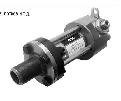
214

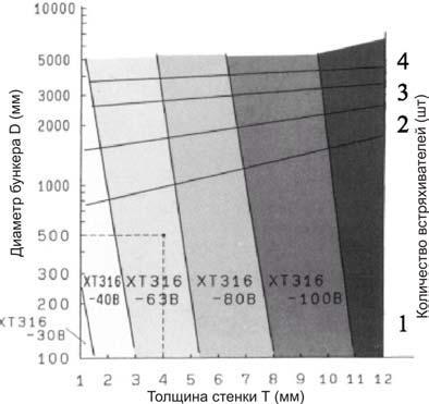
215 : D= 0, = 4, XT3-3 1.

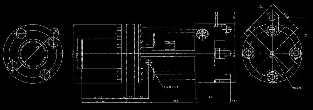
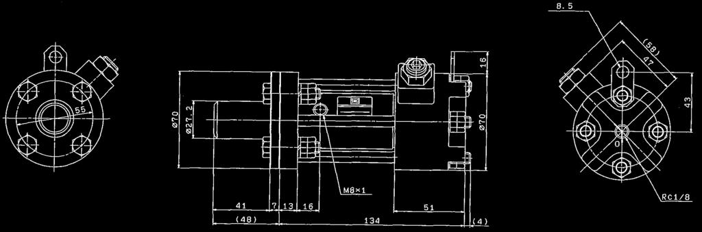
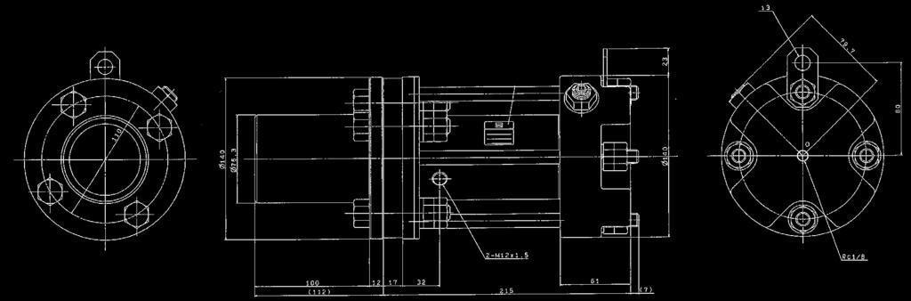
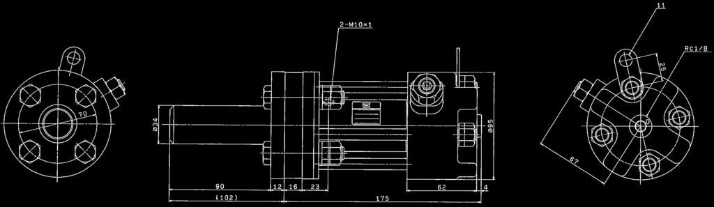
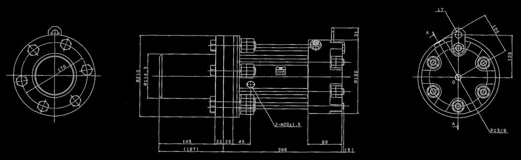
216 3 XT3- XT3- XT3-3 XT3-0 XT3-0
Magnetically Coupled Rodless Cylinder Slider Type: Ball Bushing Bearing. How to Order CY1L 25 H 300 J79W. Load voltage 5 V 200V 100 V 12 V 5 V, 12 V
 Magnetically Coupled Rodless Cylinder Slider Type: all ushing earing Series CY1L ø, ø, ø, ø, ø, ø, ø How to Order CY1L H 00 J79W Slider type (all bushing bearing) mm mm mm mm mm mm mm Magnetic holding
Series REA/REB. Sine Rodless Cylinder. Series REA (300 mm/s) Series REB (600 mm/s) RE A B REC C X C Y MQ Q M RHC MK(2) RS Q G RS H A RZQ MI W S CEP1
 Series REB (600 mm/s) RE A B REC C X C Y MQ Q M RHC MK(2) RS Q G RS H A RZQ MI W S CEP1") Sine Rodless Cylinder Series REA/REB (Maximum speed: 0 mm/s) (Maximum speed: 00 mm/s) CX CY MQ Q M RC RS A MI S CEP Series REA CE Series REB C G-S Series REA (0 mm/s) Series REB (00 mm/s) Guide type Page
Sine Rodless Cylinder Series REA/REB (Maximum speed: 0 mm/s) (Maximum speed: 00 mm/s) CX CY MQ Q M RC RS A MI S CEP Series REA CE Series REB C G-S Series REA (0 mm/s) Series REB (00 mm/s) Guide type Page
Basic type/direct mount type
 Basic type/direct mount type Series / ø, ø, ø, ø, ø, ø, ø, ø, ø3 CYS -Z CYL CYH CYF CYP 443 D- -X Technical data Magnetically Coupled Rodless Cylinder Direct mount type Series / Basic type Improved durability
Direct Mount Type. REBR Series. ø15, ø25, ø32. REA REB REC Smooth MQ RHC RZQ D- -X. Low Speed
 Direct Mount Type R Series ø, ø, ø 85 R Series Selection Fn: llowable driving force (N) MD: Maximum allowable moment when connection fitting, etc., is directly loaded (N m) Pv: Maximum operating pressure
Series CY1. Magnetic Rodless Cylinder. High Accuracy. Magnetically coupled cylinders save space and have a wide range of applications
 CAT.E - Magnetic Rodless Cylinder Series CY High Accuracy Series CYHT Series CYH Series CYL Series CYS Series CYR Allowable moment Large Series CYB Magnetically coupled cylinders save space and have a
Basic type / Direct mount type
 Basic type / Direct mount type Series / ø, ø, ø, ø, ø, ø, ø, ø, ø3 CYS CYL CY CYF Courtesy of Steven Engineering, Inc.- Ryan Way, South San Francisco, CA 0-30-Main Office: () -0-Outside Local Area: (00)
Compact Hydraulic Cylinder. ø20, ø25, ø32, ø40, ø50, ø63, ø80, ø100. How to Order Z73. Bore size. 20mm 25mm 32mm 40mm 50mm 63mm 80mm 100mm
 ompact ydraulic ylinder MPa Series KG ø, ø, ø, ø, ø, ø, ø, ø0 With uto Switch With auto switch (built-in magnet) KG DKG Mounting: asic type 0 ore size ow to Order mm mm mm mm mm mm mm 0mm Z3 Refer to "uto
Specifications. Standard Stroke Table. Bore size (mm) Number of axes 200, 300, 400, 500,
 Number of axes 200, 300, 400, 500,") Series REH Specifications Bore size mm Fluid ction Maximum operating pressure Minimum operating pressure Proof pressure mbient and fluid temperature Piston speed ubrication Stroke length tolerance Piping
Series REH Specifications Bore size mm Fluid ction Maximum operating pressure Minimum operating pressure Proof pressure mbient and fluid temperature Piston speed ubrication Stroke length tolerance Piping
/ ø6, ø10, ø16, ø20 A table cylinder suitable for short pitch mounting
 roduces a table cylinder non-rotating accuracy MXH / ø, ø, ø1, ø A table cylinder suitable for short pitch mounting Application example Auto switches offer numerous variations Reed switches, solid state
Compact Guide Cylinder
 Compact Guide Cylinder Series ø, ø, ø, ø, ø, ø, ø, ø, ø, ø ir cylinder with guide integrated that has achieved anti-lateral load and high non-rotating accuracy. Space-saving cylinder. Suitable as stoppers
CAT.ES C. Compact Guide Cylinder. SeriesMGP. ø12, ø16, ø20, ø25, ø32, ø40, ø50, ø63, ø80, ø100. New end lock type introduced to Series MGP
 CT.S-7 C Compact Guide Cylinder Series ø, ø, ø, ø2, ø, ø, ø, ø, ø, ø0 New end lock type introduced to Series . Top mount Compact Guide Cylinder Series ø, ø, ø, ø2, ø, ø, ø, ø, ø, ø0 Four mounting types
Standard Type Dual-Rod Cylinder. ø6, ø10, ø15, ø20, ø25, ø32. How to Order
 Standard Type ual-rod ylinder Series ø, ø, ø, ø, ø2, ø32 ompact Type J M L M earing type Slide bearing all bushing bearing How to Order 0 Y7W S Number of auto switches Nil 2 pcs. S pc. n "n" pcs. ore size/standard
Slider Type/Ball Bushing Bearing
 Slider Type/Ball Bushing Bearing Series ø, ø, ø, ø, ø, ø, ø D- -X 11 Series Selection E: Kinetic energy of load (J) V 2 E = ( 2 00 ) Es: llowable kinetic energy for intermediate stop using an air pressure
Compact Hydraulic Cylinder
 ompact Hydraulic ylinder Series HQ HQ Series HQ HK HN HM HS H2 H Nominal pressure:. MPa ore size :,,,,,, . MPa ompact Hydraulic ylinder Double cting/single Rod Series H Q ø, ø, ø, ø, ø, ø, ø With uto Switch
Compact Guide Cylinder Series MGQ
 Compact Guide Cylinder Series ø, ø, ø, ø, ø, ø, ø, ø, ø, ø0 ir cylinder with guide integrated that has achieved anti-lateral load and high non-rotating accuracy. Space-saving cylinder. Suitable as stoppers
SeriesMHZL2 How to Order
 Parallel Type ir Gripper Long Stroke SeriesMHZL2 How to Order 1 2 2 ore size Number of fingers 2 2 fingers 1mm mm 2mm 2mm MHZL2 D S C ction Double acting Single acting (normally open) Single acting (normally
CAT.ES20-53 E. Dual-Rod Cylinder. Series CXS. CXS Dual-Rod Cylinder with Air Cushion Compact Type Series CXSJ. New:
 CAT.ES-3 E Dual-Rod Cylinder Series New: Dual-Rod Cylinder with Air Cushion Compact Type Series J Dual-Rod Cylinder with guide function for pick-and-place applications Series! Twice the thrust Non-rotating
3 Position Cylinder. RZQ Series. Provides intermediate stop mechanism. ø32, ø40, ø50, ø63. 2-stage stroke enabled with a small increase in length
 Position ylinder Series ø, ø, ø, ø Provides intermediate stop mechanism 2-stage stroke enabled with a small increase in length Overall length of cylinder tube DQ2 Full stroke First-stage stroke dditional
High Rigidity/ High Precision Guide Type ø50, ø63. The use of two linear guides allows a maximum load of 320kg. (ø63) Rodless cylinder MY1BH SMC
 Rodless cylinder MY1BH SMC") MYHT Series High Rigidity/ High Precision Guide Type ø, ø6 The use of two linear guides allows a maximum load of kg. (ø6) Rodless cylinder MYBH SMC 2 linear guides Easy maintenance is stressed by a revolutionary
MYHT Series High Rigidity/ High Precision Guide Type ø, ø6 The use of two linear guides allows a maximum load of kg. (ø6) Rodless cylinder MYBH SMC 2 linear guides Easy maintenance is stressed by a revolutionary
Dual rod cylinder with guide function suitable for pick & place applications. Adjustable stroke range: 0 to 5 mm. Axial foot piping.
 Dual Rod Cylinder / Series ø,,,,, Dual rod cylinder with guide function suitable for pick & place applications. Ball bushing bearings and slide bearings are standard for all series. Dimensions for ball
How to Order D 30 D M9BW. Made to Order Specifications Bore size Number of. Rod end configuration Cylinder stroke (mm) Nil
 Nil") With auto switch RSG RSDG With auto switch (uilt-in magnet) uilt-in Magnet Cylinder Model If a built-in magnet cylinder without an auto switch is required, there is no need to enter the symbol for the
With auto switch RSG RSDG With auto switch (uilt-in magnet) uilt-in Magnet Cylinder Model If a built-in magnet cylinder without an auto switch is required, there is no need to enter the symbol for the
Toggle Type Air Gripper
 ø2, ø40, ø50, ø6 Ideal for gripping heavy workpiece Toggle mechanism is adopted. Holds workpiece even when pressure drops. The toggle mechanism that activates when the finger closes realizes strong and
Compact Slide. Series MXH ø6, ø10, ø16, ø20
 Compact Slide Series ø, ø, ø, ø The use of an endless track linear guide produces a table cylinder having excellent rigidity, linearity and non-rotating accuracy. Endless track linear guide Series Variations
Series CY1. Magnetically Coupled Rodless Cylinder. Accuracy. Allowable moment
 Magnetically Coupled Rodless Cylinder Series CY Accuracy Series CYS Series CYR Series CYB Series CYT Series CY Series CY Allowable moment Magnetically coupled cylinders save space and have a wide range
Series CYP. ø15, ø32 Clean Rodless Cylinder. How to Order
 ø15, ø32 Clean odless Cylinder How to Order CYP 15 200 Y59 Clean rodless cylinder Cylinder bore size 15 15 mm 32 32 mm Standard stroke ore size (mm) Standard stroke (mm) 100, 150, 200, 250, 300, 350 15/32
Series MGPS. Compact Guide Cylinder: ø50, ø80 MGP S Z73. How to Order. Applicable auto switches. Compact Guide Cylinder.
 Compact Guide Cylinder: Series S ø, Compact Guide Cylinder Compact guide cylinder Heavy duty guide rod type S Z73 mm mm How to Order Number of auto switches Nil S 2 pcs. 1 pc. Auto switch type Nil Without
Slide Unit. CX2/CXWM/CXWL Series. Slide Bearing/CX2:ø10, ø15, ø25 CXWM:ø10, ø16, ø20, ø25, ø32 Ball Bushing Bearing/CXWL:ø10, ø16, ø20, ø25, ø32
 Slide Unit CX/M/L Series Slide Bearing/CX:ø0, ø, ø5 M:ø0, ø, ø0, ø5, ø3 Ball Bushing Bearing/L:ø0, ø, ø0, ø5, ø3 Provided with shock absorbers to absorb impact and noise. The slide unit can absorb energy
Series MGP. Compact Guide Cylinder. New end lock type introduced to Series MGP. ø12, ø16, ø20, ø25, ø32, ø40, ø50, ø63, ø80, ø100
 Compact Guide Cylinder Series ø, ø, ø, ø2, ø, ø, ø, ø, ø, ø0 New end lock type introduced to Series.22- CL MLG CN CNG MNB CNS CLS CB CV/MVG CXW CXS CXT MX MXU MXH MXS MXQ MXF MXW MXP MG MGQ MGG MGC MGF
Mini Free Mount Cylinder
 Mini Free Mount Cylinder Series ø, ø, ø, ø, ø, ø1, ø Series 1 ction Stroke 1 2 0 0 0 Clean uto switch series None Rod end Male threaded Without thread Solid state switch D-F D-M9 D-M9 W Female threaded
Dual rod cylinder with guide function for pick & place applications.
 Dual Rod Cylinder Series CXS ø, ø0, ø, ø, ø2, Dual rod cylinder with guide function for pick & place applications. Series CXS Twice the thrust Non-rotating accuracy ±0. MX MY CY MG CX - Ball bushing bearings
Slide Unit. Bore size. ø15 (2) ø10 (2) ø16 (3) ø20 (2) Ball bushing bearing Slide bearing. ø25 (3) (3) ø32 (3)
 ø10 (2) ø16 (3) ø20 (2) Ball bushing bearing Slide bearing. ø25 (3) (3) ø32 (3)") Slide Unit Series CX/M/L Slide Bearing/CX:ø, ø, ø5 M:ø, ø6, ø0, ø5, ø3 Ball Bushing Bearing/L:ø, ø6, ø0, ø5, ø3 Provided with shock absorbers to absorb impact and noise. The slide unit can absorb energy
Slide Unit Series CX/M/L Slide Bearing/CX:ø, ø, ø5 M:ø, ø6, ø0, ø5, ø3 Ball Bushing Bearing/L:ø, ø6, ø0, ø5, ø3 Provided with shock absorbers to absorb impact and noise. The slide unit can absorb energy
CAT.ES20-53 E -UK. Dual-Rod Cylinder. Series CXS. CXS Dual-Rod Cylinder with Air Cushion Compact Type Series CXSJ. New:
 CAT.ES-3 E -UK Dual-Rod Cylinder Series New: Dual-Rod Cylinder with Air Cushion Compact Type Series J Dual-Rod Cylinder with guide function for pick-and-place applications Series! Twice the thrust Non-rotating
Series RQ. The new standard for the future. Compact Cylinder with Air Cushion. ø20, ø25, ø32, ø40, ø50, ø63, ø80, ø100
 1 Compact Cylinder with ir Cushion ø, ø, ø, ø, ø, ø, ø, ø The new standard for the future J CQ U - NW ir Cushion Cylinder Uses a unique air cushion mechanism with no cushion ring. Size ø, ø and ø newly
3 Position Cylinder. ø32, ø40, ø50, ø63 RZQ CDQ2. Bore size (mm)
") Position ylinder Series ø, ø, ø, ø Provides intermediate stop mechanism 2-stage stroke enabled with a small increase in length Overall length of cylinder tube First-stage stroke Full stroke dditional cylinder
Position ylinder Series ø, ø, ø, ø Provides intermediate stop mechanism 2-stage stroke enabled with a small increase in length Overall length of cylinder tube First-stage stroke Full stroke dditional cylinder
Miniature Guide Rod Cylinder ±0.1. Mounting from 2 directions
 Miniature Guide Rod Cylinder Series Non-rotating accuracy : Height ±0.1 Mounting from 2 directions idth Overall length Two auto switches can be mounted even for mm strokes Integral wiring/piping to one
Dual rod cylinder with guide function suitable for pick & place applications. Adjustable stroke range: 0 to 5 mm. Axial foot piping.
 Dual Rod Cylinder J/ Series ø, ø, ø, ø, ø, Dual rod cylinder with guide function suitable for pick & place applications. Ball bushing bearings and slide bearings are standard for all series. Dimensions
Precision Cylinder. MTS Series. ø8, ø12, ø16, ø20, ø25, ø32, ø40 MXH MXS MXQ MXQ MXF MXW MXJ MXP MXY MTS D- -X. Series Variations MTS8
 Precision Cylinder Series, ø, ø6, ø, ø, ø, ø MXS Series Variations Model 8 Standard stroke (mm) 7 7 Rod end configuration Cushion Rubber bumper End lock Made to Order Rod Variable stroke/ through-hole
Rotary Clamp Cylinder
 Rotary Clamp Cylinder ø, ø, ø, ø, ø, ø, ø, ø llowable moment of inertia 3 times higher New structure! New series Overall length is the same as the existing products! Mounting dimensions are interchangeable
Platform Cylinder. CXT Series. ø12, ø16, ø20, ø25, ø32, ø40. A highly rigid and highly accurate slide table integrated with an actuator.
 Platform Cylinder Series ø, ø, ø, ø, ø, ø highly rigid and highly accurate slide table integrated with an actuator. Two types of guide rod bearings to accommodate your application For heavy loads all bushing
Series Basic Type. ø10, ø16, ø20, ø25, ø32, ø40, ø50, ø63, ø80, ø100. Series MY1B
 MY Series asic Type ø, ø, ø, ø, ø, ø, ø, ø, ø, ø0 Series MY earing Minimizing the unit size (dimensions) and combination with other guides is possible. efore Operating Series MY Maximum llowable Moment/Maximum
Series MK ø12, ø16, ø20, ø25, ø32, ø40, ø50, ø63
 otary lamp ylinder/standard Series MK ø, ø, ø, ø, ø, ø, ø5, ø ow to Order MK 1 3 S otary clamp cylinder Mounting Symbol Style ore size Through hole & both ends tapped (Standard) ø, ø oth ends tapped Through
Series CYP. Clean rodless cylinder ø15, ø32. How to Order
 Series Clean rodless cylinder ø15, ø32 How to Order ir cylinder Clean rodless cylinder ore size (mm) 15 32 15 Cylinder bore size 15 15mm 32 32mm TN TF Port type M5 x 0.8 15 c NPT Standard stroke Standard
Sine Cylinder. REC Series. ø20, ø25, ø32, ø40. Allows high speed transfer of work with dramatically reduced shock/impact. REA REB REC Smooth
 Sine Cylinder Series,,, llows high speed transfer of work with dramatically reduced shock/impact. RE RE RC Velocity curve Time Sine cylinder Current cylinder Sine Cylinder Series,,, llows rapid transfer
High Precision Scale Cylinder. How to Order. Connector. Cable suffix Nil Extension cable C Extension cable & connector
 Non-rotating Type High Precision Scale Cylinder Series CEP1 ø12, ø How to Order CEP1 12 0 F9N L F High precision scale cylinder Mounting bracket Direct mounting front tapped type Foot type Front flange
Rotary Clamp Cylinder
 Rotary Clamp Cylinder ø, ø, ø, ø, ø, ø, ø, ø llowable moment of inertia 3 times higher New structure! New series Overall length is the same as the existing products! Mounting dimensions are interchangeable
Series MXH/ ø6, ø10, ø16, ø20
 Compact Slide Series / ø, ø, ø, ø The use of an endless track linear guide produces a table cylinder having excellent rigidity, linearity and non-rotating accuracy. CL MLG CNA CNG MNB CNS CLS CB CV/MVG
Sine Cylinder. Series REC. ø20, ø25, ø32, ø40 REA REB REC C Y C X MQ RHC RZQ. Sine cylinder. Individual. Velocity curve. Speed. Conventional cylinder
 Sine Cylinder Series,,, llows high speed transfer of work with dramatically reduced shock/impact. Velocity curve RE RE Speed Time Sine cylinder Conventional cylinder 3 Sine Cylinder Series,,, llows rapid
Dual Rod Cylinder: Double Rod Type. How to Order. Load voltage Auto switch model Perpendicular In-line 3-wire (NPN equivalent) Y7NWV Y7NW 5 V, 12 V
 Y7NWV Y7NW 5 V, 12 V") Dual Rod Cylinder: Double Rod Type eries CXW ø, ø, ø, ø, ø2, ø32 CX W L How to Order 0 Y7W M L Double rod type earing type lide bearing all bushing bearing ore size/troke ore size,,,,,,,,,,,,,,, 2, 32,
Dual Rod Cylinder: Double Rod Type eries CXW ø, ø, ø, ø, ø2, ø32 CX W L How to Order 0 Y7W M L Double rod type earing type lide bearing all bushing bearing ore size/troke ore size,,,,,,,,,,,,,,, 2, 32,
MHR3/MDHR3 Series. Rotary Actuated Air Gripper/3-Finger Type. Size: 10, 15 MDHR 3 10 R M9N S. How to Order. Without auto switch
 Rotary ctuated ir Gripper/3-Finger Type MHR3/MDHR3 Series Size:, 1 How to Order Without auto switch MHR 3 R Connecting port R ody side R: ody side Port With auto switch (uilt-in magnet) MDHR 3 R M9N S
Air Cylinder: With End Lock. How to Order. Port thread type. Cylinder stroke (mm) For more information, please refer to the next page.
 For more information, please refer to the next page.") ir Cylinder: With End ock Series C ø, ø, ø, ø, ø Without auto switch With auto switch F G C D T With auto switch Mounting style asic style xial foot style Rod side flange style Head side flange style Single
ir Cylinder: With End ock Series C ø, ø, ø, ø, ø Without auto switch With auto switch F G C D T With auto switch Mounting style asic style xial foot style Rod side flange style Head side flange style Single
Series. High Precision Guide Type. ø10, ø16, ø20, ø25, ø32, ø40. End lock type capable of holding a position at the stroke end (except bore size ø10)
") MYH Series High Precision Guide Type ø0, ø, ø, ø, ø, ø Bearing Uses a linear guide to achieve high linearity and high repeatability Linear guide Series MYH End lock type capable of holding a position at
MYH Series High Precision Guide Type ø0, ø, ø, ø, ø, ø Bearing Uses a linear guide to achieve high linearity and high repeatability Linear guide Series MYH End lock type capable of holding a position at
Series MY1. Five guide models allow a wide range of selections. Mechanically Jointed Rodless Cylinder. High. Accuracy. Allowable moment Large
 CT.ES- D Mechanically Jointed Rodless Cylinder Series MY igh ccuracy igh Rigidity igh Precision Guide Type Series MYT igh Precision Guide Type Series MY Cam Follower Guide Type Series MYC asic Type Series
Compact Rotary Actuator
 Compact Rotary ctuator Series Rack & Pinion Style/:,,,, : 17 mm : mm : 29 mm : 33 mm : 37 mm CR2 CRU2 CR1 MSU CRJ Rotation 360 type MSQ 360 MSZ MSQ MRQ Series Variations Page Rotating angle 80 to 0 170
Compact Rotary Actuator
 Compact Rotary ctuator Series Rack & Pinion Style/:,,,, : 17 mm : mm : 29 mm : 33 mm : 37 mm 360 type 360 CR2 CRU2 CR1 MSU CRJ CR1 MSQ MSZ MSQ MRQ Series Variations Standard Made to Order Rotating angle
Series C95 ø32, ø40, ø50, ø63, ø80, ø100
 ISO Cylinder Series C ø, ø, ø, ø, ø, ø0 Dimensions conform to ISO 1, VDMA 2, CETOP RP3P. CJ1 CJP CJ2 CM2 C CG1 M C CA1 CS1 Variations Series Action Style asic Standard variations uit-in magnet Stainless
140 mm. Mechanically Jointed Rodless Cylinder. Series MY3A/3B. Scale: 100% Height reduced by 36% at the maximum * Overall length reduced by
 CT.ES0- Mechanically Jointed Rodless Cylinder Height reduced by % at the maximum * Scale: 00% (MY-00) Overall length reduced by mm at the maximum * Comparison with Series MYB High functionality with reduced
Platform Cylinder. ø12, ø16, ø20, ø25, ø32, ø40. Series CXT 12 CXT 16 CXT 20 CXT 25 CXT 32 CXT 40
 Platform Cylinder Series ø, ø, ø, ø, ø, ø highly rigid and highly accurate slide table integrated with an actuator. Two styles of guide rod bearings to accommodate your application For heavy loads all
Compact Cylinder. With a short overall length, the space saving cylinder helps to make various jigs and equipment more compact.
 Compact Cylinder Series CQ ø, ø, ø, ø, ø, ø, ø, ø, ø, ø, ø, ø1, ø With a short overall length, the space saving cylinder helps to make various jigs and equipment more compact. Variations Standard Series
Series MHZJ2. How to Order MHZJ2 16 D F9PV. Body option. Nil. Port. Port
 Parallel Type ir Gripper How to Order 1 1 2 Bore size mm 1mm 1mm 2mm mm MHZJ2 1 D F9PV Number of fingers 2 2 fingers D S C ction Double acting Single acting (normally open) Single acting (normally closed)
Brake mechanism has been compactly integrated into the slide table which enables intermediate stops of the rodless cylinder. Diaphragm.
 rake mechanism has been compactly integrated into the slide table which enables intermediate stops of the rodless cylinder. Large holding brake force Force from 4 brake springs hold slide tightly. Holding
Compact Cylinder/Plate type
 Compact Cylinder/Plate type Series :,,, Width: Reduced by up to % (compared with SMC series) Total length: Reduced by up to % Volume: Reduced by up to 1% Weight: Reduced by up to % (compared with SMC series
Rotary Actuated Air Gripper
 Rotary ctuated ir Gripper MHR, MDHR/MHR3, MDHR3 -finger type: Size, 15,, 3/ 3-finger type: Size, 15 High Precision - Repeatability ±.1 mm Parallel opening and closing mechanism utilizing a cross roller
Compact Rotary Actuator
 Compact Rotary ctuator CRQ2 Series Rack & Pinion Type/:,,,, : 17 mm : mm : 29 mm : 33 mm : 37 mm CR 2 CR1 MSU CRJ CR1 CRQ2 MSQ MSZ Rotation 360 type 360 CRQ2 MSQ MRQ Series Variations Page Rotating angle
How to Order. Manual release type. Lock position. H Head end lock. With rod boot. Nil J K M9NWV M9NW H7C M9PWV M9PW M9BWV M9BW M9NAV M9NA M9PAV M9PA
 Courtesy of CM/Flodyne/Hydradyne Motion Control Hydraulic Pneumatic Electrical Mechanical (0) - www.cmafh.com CDG1 With auto switch (uilt-in magnet) Mounting style asic style L xial foot style F Rod side
Round Type Hydraulic Cylinder
 Round Type ydraulic Cylinder CM Series CQ CK C CM CS C C D- CM Series ominal pressure: 3. MPa ore size :,,, 3 3. MPa Round Type ydraulic Cylinder CM Series ø, ø, ø, ø pplicable uto Switches/Refer to pages
Compact Cylinder: Standard Type Double Acting, Single Rod. How to Order 30 D F9BW. Body option <Standard stroke> Nil C M. Double acting.
 Compact Cylinder: Type Series ø, ø, ø, ø How to Order Without auto switch D With auto switch CDQS D FW S Number of auto switches L F G D, uilt-in magnet Mounting style Through-hole/oth ends tapped common
Elliptical design for space-savings
 Plate Cylinder Series,,,, By adopting an elliptical piston design, a slim, square shaped body has been achieved, resulting in a space-saving cylinder with unrestricted mounting directions. Elliptical design
Compact Guide Cylinder with Lock
 Compact Guide Cylinder with Lock Series,,,, ø,,, ø0 CLG CL CN2 MLC Drop prevention when the pressure of air source is decreased or the residual pressure is released. Drop prevention for press fitting jig
Mechanically Jointed Hy-rodless Cylinder with Brake
 Mechanically Jointed y-rodless Cylinder with Brake Series ø, ø, ø Brake mechanism has been compactly integrated into the slide table which enables intermediate stops of the rodless cylinder. Large holding
Hygienic Design Cylinder
 CT.EUS- -UK Hygienic Design Cylinder New Round type Series HY has been added. water resistant cylinder configured for easy cleaning ISO standard type Series HYC asic type Series HYQ With guide Series HYG
Series MGC ø20, ø25, ø32, ø40, ø50
 Compact Guide Cylinder Series MGC ø, ø, ø, ø, ø Linear Transfer Unit with compact guide body and front plate Grease nipple offers easy lubrication for bearings Compact front plate and guide body Space
A rectilinear rotation unit that compactly integrates a slim cylinder and a rotary actuator.
 Rotary Cylinder MRQ Series :, A rectilinear rotation unit that compactly integrates a slim cylinder and a rotary actuator. The timing of the rectilinear and rotational movements can be set as desired.
Compact Cylinder: Standard Type Double Acting, Single Rod. ø12, ø16, ø20, ø25, ø32, ø40, ø50, ø63, ø80, ø100. How to Order. Piping A76H A72H 200 V
 Compact Cylinder: Standard Type Double cting, Single Rod,,,,,,,,, How to Order Without auto switch D With auto switch CDQ2 D JW S uilt-in magnet Mounting style Through-hole (Standard) oth ends tapped style
Free Mount Cylinder. Series CU. A space-saving air cylinder with multiple surfaces capable of mounting directly. Offered in rich variations.
 Free Mount Cylinder Series CU A space-saving air cylinder with multiple surfaces capable of mounting directly. Offered in rich variations. Space-saving The multiple surface direct mounting with a square
Free Mount Cylinder. Series. Series CU CAT.EUS20-95 B -UK. Space-saving. Auto Switch Capable P. 4, 23, 37 P. 45 P. 43
 CAT.EUS- B -UK Free Mount Cylinder A space-saving air cylinder with multiple surfaces capable of direct mounting. Offered in many variations. Space-saving The multiple surface direct mounted rectangular
Round Type Hydraulic Cylinder
 Round Type ydraulic Cylinder Series CM CQ Series CM CK C CM CS C2 C ominal pressure: 3. MPa ore size :,,, 233 3. MPa Round Type ydraulic Cylinder Series C M ø, ø, ø, ø With uto Switch ow to Order CM L
Mechanically Jointed Rodless Cylinders
 Mechanically Jointed Rodless Cylinders MY Series Basic short type (Rubber bumper) MY Series Bore sizes ø, ø, ø0 added MYB MY Basic standard type (ir cushion) MYB MYB Series MYM MYC MY MY T Bore sizes ø,
Specifications MHC2-10D MHC2-16D MHC2-20D MHC2-25D MHC2-10S. Double acting MHC2-16S. Single acting MHC2-20S MHC2-25S. Angular style air gripper
 Angular Style Air Gripper Standard Type Series MHC2 Size: 10, 16, 20, 25 A large amount of gripping force is provided through the use of a double piston mechanism, while maintaining a compact design. Built-in
Guide Table. MGF Series
 Guide Table MGF Series ø, ø, ø0 Low-profile compact cylinder utilizes a large concentric guiding sleeve to provide excellent eccentric load resistance. Mounting height greatly reduced Low-profile cylinder
Air Cylinder: Standard Type Double Acting, Single Rod. How to Order. Standard stroke (mm) ø6 15, 30, 45, 60. Cushion Nil A
 ø6 15, 30, 45, 60. Cushion Nil A") ø, ø, ø L F D Without auto switch With auto switch style asic style Axial foot style Rod side flange style Double clevis style (Except ø) ore size mm mm mm How to Order Standard stroke (mm) ø,,, ø,,,,
ø, ø, ø L F D Without auto switch With auto switch style asic style Axial foot style Rod side flange style Double clevis style (Except ø) ore size mm mm mm How to Order Standard stroke (mm) ø,,, ø,,,,
Series CRQ2. Compact Rotary Actuator Rack & Pinion Style. Size: 10, 15, 20, 30, 40. Rotary actuator body serves as a flange.
 Compact Rotary ctuator Rack & Pinion Style Series CRQ2 :,,,, Unidirectional pipe connection possible uilt-in cushion, : Rubber bumper,, : ir cushion Equipped with an angle adjusting mechanism Double piston
Mechanically Jointed Rodless Cylinder High Precision Guide Type. How to Order 16 G 300 L M9N. Stroke. Refer to Standard Stroke table.
 Mechanically Jointed Rodless ylinder igh Precision uide Type eries MY/T ø, ø, ø T MY uide type igh precision guide with single axis igh precision guide with double axis ymbol Nil TN TF Type M thread Rc
22mm Space required between the bottom of the cylinder body and your equipment is reduced.
 Compact Guide Cylinder ø2,,, ø2,,, ø0, ø63,, ø0 With air cushion Water resistant cylinder are now available. New Up to 7% Weight reduced! New Weight reduced by up to 7% with a shorter guide rod and thinner
Series RSH/RS1H. To stop pallets gently. Heavy Duty Stopper Cylinder. Stopper cylinder with built-in shock absorber. ø20, ø32 ø50, ø63, ø80
 1 eavy Duty Stopper Cylinder Series RS/RS1 ø, ø ø, ø, ø To stop pallets gently CX CY RC RS A MI S C G5-S Stopper cylinder with built-in shock absorber - -9-1 2 eavy Duty Stopper Cylinder Series RS/RS1
CAT.ES20-53 E -UK. Dual-Rod Cylinder. Series CXS. CXS Dual-Rod Cylinder with Air Cushion Compact Type Series CXSJ. New:
 CAT.ES-3 E -UK Dual-Rod Cylinder Series CXS New: CXS Dual-Rod Cylinder with Air Cushion Compact Type Series CXSJ Dual-Rod Cylinder with guide functio for pick-and-place applications Series CXS! Twice the
Compact Cylinder: Large Bore Size Type Double Acting, Double Rod. How to Order. Cushion C Rubber bumper. Action. D Double acting
 Compact Cylinder: Large Bore Size Type Double Acting, Double Rod Series CQ2W ø, ø, ø, ø, ø Without auto switch With auto switch B Built-in magnet CQ2WB CDQ2WB Double rod ounting style Through-hole/Both
Guide Table. ø40, ø63, ø100
 Guide Table Series MGF ø, ø, ø Low-profile compact cylinder utilizes a large concentric guiding sleeve to provide excellent eccentric load resistance. Mounting height greatly reduced Low-profile cylinder
Valve Mounted Cylinder Double Acting, Single Rod. How to Order. Electrical entry. L L plug connector M M plug connector. G Grommet
 L F Mounting style asic style xial foot style Rod side flange style With auto switch CVJ L CDVJ L 6 6 How to Order pplicable uto Switches/Refer to pages to for further information on auto switches. Type
Small Bore Hydraulic Cylinder
 Small ore ydraulic Cylinder CN Series CQ CK CN CM CS C C D- CN Series Nominal pressure: MPa ore size :,,, Stainless Steel Tube Small ore ydraulic Cylinder for MPa CN Series ø, ø, ø, ø Equipped with cushion
Slide Unit. Series CXWM/CXWL. Slide bearing/cxwm: ø10, ø16, ø20, ø25, ø32 Ball bushing bearing/cxwl: ø10, ø16, ø20, ø25, ø32
 Slide Unit Series M/ Slide bearing/m: ø10, ø16, ø0, ø5, ø3 Ball bushing bearing/: ø10, ø16, ø0, ø5, ø3 Variations Slide unit Provided with shock absorbers to absorb impact and noise. The slide unit can
Air Cylinder. ø6, ø10, ø16. Easy installation. Reduced piston rod deflection
 ir Cylinder Series CJ2 ø, ø, ø CJ1 CJP Improved wear resistance The bearing portions of the rod cover and the clevis have been improved in wear resistance to ensure the longevity of the cylinder. Series
Rod end male thread. With rubber bumper 056(9/16") 075(3/4") 106(1 1/16") 150(1 1/2") 250(2 1/2") 300(3")
 075(3/4) 106(1 1/16) 150(1 1/2) 250(2 1/2) 300(3)") T.ID0-1 New ompact ylinder Series NQ8 ore size: 06(9/16 ),(/ ),106(1 1/16 ),(1 1/ ) 00( ),0( 1/ ),00( ),00( ) Now available in 00 ( ) and 00 ( ) bore sizes Standard type ctuation Style uilt-in magnet Rod
T.ID0-1 New ompact ylinder Series NQ8 ore size: 06(9/16 ),(/ ),106(1 1/16 ),(1 1/ ) 00( ),0( 1/ ),00( ),00( ) Now available in 00 ( ) and 00 ( ) bore sizes Standard type ctuation Style uilt-in magnet Rod
Non-rotating Double Power Cylinder. Double Power Cylinder MGZ. (without non-rotating MGJ MGP -Z MGP MGPW MGQ MGG MGC MGF MGT D- -X
 Non-rotating Double Power Cylinder Double Power Cylinder (without non-rotating Series Series R mechanism) MGJ -Z W MGQ MGG MGC MGF MGT 23 D- -X Non-rotating Double Power Cylinder Double extension output
MGZ. Non-rotating Double Power Cylinder. Double Power Cylinder MGJ MGP MGPW MGQ MGG MGC MGF MGT D- -X
 Non-rotating Double Power Cylinder Double Power Cylinder (without non-rotating Series Series R mechanism) 23 MGJ -Z W MGQ MGG MGC MGF MGT D- -X Tube rod diameter External dimension Non-rotating Double
Compact Guide Cylinder
 Compact Guide Cylinder Series ø2, ø, ø, ø2, ø, ø, ø, ø, ø, ø0 Series standard type and series high precision ball bushing bearing type (except with end lock) products have been remodeled for a lightweight
Compact Guide Cylinder Series MGP
 Compact Guide Cylinder Series MGP ø2, ø, ø, ø, ø, ø, ø, ø,, ø0 MGJ MGP MGQ MGG MGC MGF MGZ MGT Series Variations Series Bearing type Cushion 2 0 Page Standard type MGP With air cushion MGP With end lock
Series MXS ø6, ø8, ø12, ø16, ø20, ø25
 ork table and air cylinder are integrated compactly. ir slide table is ideal for precise assembly. CL Repeatability of work mounting lush mountable auto switches n installed auto switch in the housing
Low Profile Air Gripper. Series MHF2. Low profile air gripper with space-saving design is newly released. 5-77
 Low Profile Air Gripper Low profile air gripper with space-saving design is newly released. 5-77 Low Profile Air Gripper Height is approximately / the size of an equivalent Series MHZ2. MHZ2-D 42 Bore
240% 19% reduced. Compact Slide. MXH Series. Improved by up to. With new high rigidity linear guide. 369g. ø6, ø10, ø16, ø g.
 Compact Slide Series ø, ø, ø, ø RoHS Allowable moment MXS Improved by up to MXQ MXQ 2% MXF MXW MXJ MXP MXY With new high rigidity linear guide MTS Allowable moment improvement illustrated below Allowable
Rotary Table/Vane Style
 Rotary Table/Vane Style Series Size: 1, 3, 7, 20 Table top deflection mm or less High Precision Peripheral table deflection mm or less X Series B Series A 147 Rotary Table Values inside ( ) are for Series