Slide Unit. Bore size. ø15 (2) ø10 (2) ø16 (3) ø20 (2) Ball bushing bearing Slide bearing. ø25 (3) (3) ø32 (3)
|
|
|
- Meagan Williamson
- 6 years ago
- Views:
Transcription


1 Slide Unit Series CX/M/L Slide Bearing/CX:ø, ø, ø5 M:ø, ø6, ø0, ø5, ø3 Ball Bushing Bearing/L:ø, ø6, ø0, ø5, ø3 Provided with shock absorbers to absorb impact and noise. The slide unit can absorb energy in a wide range, in high speed, low-load applications to low speed, high-load applications, without requiring adjustments. Ensures high positional accuracy. A high level of positional accuracy can be attained because the two parallel piston rods prevent the rods from rotating, and the workpiece mounting surface and the parallelism of the piston rods are made highly precise. Auto switches can be installed. Smooth operation and high thrust. Mountable on the housing or on the plate. The slide unit can be mounted on the housing or on the plate, depending on the application. It can also be bolted from the bottom or from the top. The piping can be fitted to the port in any of the three positions, according to how the unit is mounted. <Fixing the plate> The housing moves. Housing Plate Mounting from the bottom side <Fixing the housing> The plate moves. Mounting from the bottom side Mounting from the upper side Mounting from the upper side Series Variations Bearing type Bore size Stroke Accessory Auto switch mounting Page Series CX Double rod type (Basic type, compact) ø () ø 464 Slide unit Ball bushing bearing Slide bearing Series M Built-in shock absorber type Series L Built-in shock absorber type Note ) Only type E (Reed switch) is applicable as an auto switch when mounting a housing of ø. Note ) The shock absorbers are to be mounted on the both sides for the 5 stroke of Series M to 5. Note 3) The shock absorber is to be mounted on one side of the plate for the 5 stroke of Series M0, M3, L3 and the 50 stroke of Series M3. ø5 ø ø6 ø0 ø5 ø3 ø ø6 ø0 ø5 ø3 () () (3) () (3) (3) (3) () () Plate mounting With end lock Housing mounting CX
2 0 Series CX/M/L Prior to Use Maximum Allowable Moment: CXN, M, L Operate within the operating range and under the allowable moment indicated in the table below. CXN M (Slide bearing) L (Ball bushing bearing) 3 5 Allowable M (= M3) moment (N m) Cylinder stroke Allowable Moment (M) (N m) Bore size CXN M L Note) M is steady regardless of the strokes. Allowable Kinetic Energy Load mass and cylinder speed should be observed within the range given in the graph below. To adjust the cylinder speed, use a speed controller Load mass (kg) CXN5 CXN L5 CXN5- B, M5 0 6 CXN- B CXN CXN- B Cylinder speed (mm/s) 46
3 Series CX Prior to Use. Changing from the non-auto switch specifications to the auto switch specifications. Changing mounting style of the auto switch specifications Series CX. In Series CX, to change from the specification without auto switch to the plate mounting style with auto switch or to the housing mounting style with auto switch, refer to tables () and () before ordering. Without auto switch: Plate mounting style with auto switch: Housing mounting style with auto switch: CXN CDPXN S Table () CDBXN M Table (). In Series CX, to change from the plate mounting style with an auto switch to the housing mounting style with an auto switch or vice versa, refer to tables () and () before ordering. Plate mounting style with auto switch: Housing mounting style with auto switch: CDPXN S Table () CDBXN M Table () Table () Plate Mounting Style with Auto Switch (CDPXN ) Component Parts for Mounting Switches and No. of Component Parts Component parts Material ø ø ø5 Assembly model no. for mounting switch CDPXN S- CDPXN S- CDPXN 5S- Switch mounting block Block mounting screw Switch mounting screw Hexagon nut Magnet Socket Plug (M-5P) Aluminum alloy Chrome steel/ Chrome steel/ Carbon steel/ Brass/Electroless nickel plated Brass/Electroless nickel plated () () Note ) mark indicates strokes. Note ) In the case of ø, the 5 mm stroke has two magnets that are bonded in the holes on the side of the housing. Those with strokes of 50 mm to 0 mm have one magnet. Those with other bore sizes have a built-in magnet in their housings. Table () Housing Mounting Style with Auto Switch (CDBXN ) Component Parts for Mounting Switches and No. of Component Parts Component parts Magnet mounting block ass'y Switch mounting rail Spacer Block mounting screw Screw for mounting rail Switch mounting screw Hexagon nut Hexagon socket head plug Material Aluminum alloy Aluminum alloy Aluminum alloy/anodized Chrome steel/ Chrome steel/ Chrome steel/ Carbon steel/ Chrome steel/ ø ø ø5 Assembly model no. for mounting switch CDBXN M- CDBXN M- CDBXN 5M- Note ) mark indicates strokes. Note ) For ø, CXN- can be changed to CDBXN-, but note that CDPXN cannot be changed to CDBXN-. CX 463
4 Slide Unit/Double Rod Type Series CX Slide Bearing: ø, ø, ø5 How to Order Port thread type Symbol Type Nil M thread Rc /8 TN NPT /8 TF G /8 Bore size ø, ø ø5 CX N 0 B With auto switch C DB X N 0 B J79W Cylinder with auto switch Symbol Specifications/Mounting DB With auto switch/ Housing mounting DP With auto switch/ Plate mounting N H Type Non-lube type Air-hydro type (Except ø) Bore size/stroke ø 5, 50, 75, 0 ø 5, 50, 75, 0, 5, 0, 75, 00 ø5 5, 50, 75, 0, 5, 0, 75, 00 For ø and ø5, strokes up to 300 are available as made-to-order. (-XB) Cushion (Option) Nil With adjusting bolt ( pcs.) B With shock absorber ( pcs.) BS With shock absorber ( pc.) Made to Order Refer to page 465 for Made to Order specifications. Number of auto switches Nil pcs. S pc. n n pcs. Auto switch Nil Without auto switch (Built-in magnet) For the applicable auto switch model, refer to the table below. Applicable Auto Switch/Refer to pages 79 to 87 for further information on auto switches. Load voltage Auto switch part no. Applicable Auto Switch/Refer to Wiring page pages 79 to 87 for further information on auto switches. Type Solid state switch Reed switch Special function Diagnostic indication (-color indication) Water resistant (-color indication) With diagnostic output (-color indication) Electrical entry Grommet Connector Grommet Grommet Connector Grommet (Output) 3-wire (NPN) 3-wire (PNP) -wire 3-wire (NPN) 3-wire (PNP) -wire 4-wire (NPN) 3-wire -wire 3-wire -wire 4V 4V 4V DC 5V, V V 5V, V V 5V, V 5V V 5V, V V 5V, V 5V V 5V, V Lead wire length symbols: 0.5 m Nil (Example) F79W 3 m L (Example) F79WL 5 m Z (Example) F79WZ None N (Example) J79CN 464 Indicator light Yes Yes Yes No Yes No No AC 00V 0V 0 V or less 4 V or less 0V 0 V or less Refer to pages 784 and 785 for details of auto switches with a pre-wired connector. Auto switches are shipped together (not assembled). Electrical entry Applicable cylinder size Housing mounting Plate mounting Lead wire length (m) 0.5 (Nil) Pre-wired connector Perpendicular In-line F7NV F7PV F79 F7P IC circuit F7BV J79C J79 ø IC F7PW ø circuit Relay, F7BWV J79W ø5 PLC ø5 F7BAV F7BA F7NWV F79W ø F79F IC circuit A76H IC circuit A7 A7H ø ø A73 A73H ø A80 A80H IC circuit ø5 A73C ø5 Relay, A80C IC PLC E76A circuit E73A ø E80A IC circuit Solid state auto switches marked with are produced upon receipt of order. 3 (L) 5 (Z) None (N) Applicable load
 With shock absorber Cushion Stroke adjustable range Max.")
5 Slide Unit/Double Rod Type Series CX Specifications Type Fluid Proof pressure Max. operating pressure CXN Min. operating pressure CX CX 5 Ambient and fluid temperature With adjusting bolt Piston speed (Non-lube) With shock absorber Cushion Stroke adjustable range Max. load mass () Non-rotating accuracy Except piston rod ( deflection ) CXN CX CX 5 CXN CX CX 5 Non-lube Air.5 MPa.0 MPa 0. MPa 0. MPa 0. MPa C to +60 C Air-hydro type Hydraulic fluid 30 to 00 mm/s Refer to Table (). 30 to 500 mm/s With shock absorber (Option) Standard stroke: ± mm 9.8 N 9.4 N 58.8 N ±0. ±0.04 ±0.0 Straight knock pin ( pcs.), (-X38) Accessory (Option) () Note ) Place the center of gravity of the load as close to the center of the slide unit as possible during operation. If they are placed far apart, consult with SMC. Note ) -X38 has a stroke adjustable range of mm on one side. Table () Air-hydro/Piston Speed CXH CXH5 Plate mounting Note ) Refer to the below. 5 to 40 mm/s Housing mounting 5 to 50 mm/s 5 to 0 mm/s Note ) Consult with SMC when the air-hydro type is mounted on a plate. Note ) Consult with SMC when units are used at a low speed ( mm/s or faster) (when intermediate stops are not required) since -XB3 (Low speed specification) is available. Note 3) When using the air-hydro type, use the double side hydro unit. Shock Absorber Specifications Symbol Made to Order Specifications (For details, refer to pages 85 to 0.) Specifications Applicable slide unit Maximum energy absorption (J) Stroke absorption Max. collision speed (m/sec) Max. operating frequency (cycle/min) Max. allowable thrust (N) Ambient temperature range ( C) Extended Spring force (N) Retracted Mass (g) Theoretical Output RB0805 CXN, CX to 5 to 80 RB06 CX The above shows the maximum absorption energy per cycle. Accordingly, the operating frequency can be increased in accordance with the absorption energy. The shock absorber service life is different from that of the cylinder body depending on the operating conditions. Refer to the RB Series Specific Product Precautions for the replacement period. CX XB XB3 X46 X38 X68 X69 XC Long stroke type Low speed cylinder (5 to 50 mm/s) Hollow piston rod Adjustable stroke CX helical insert thread built-in magnets Fluororubber seals CXN CX CX 5 Rod size Piston area (mm ) Note) Theoretical output (N) = Pressure (MPa) x Piston area (mm ) Operating pressure (MPa) (N)
 00.")
 Pressure port Operating direction Left Right A B Standard side of housing (Mounting side)")
.94 4. 9.8 50 0.06 0.09 0.03 0 0.07 0.08 0.0 0 0.30 0. 0.09 0 0.50 0.6 00 0.8 0.08 When center loading is added to the center of the plate Deflection width 00.0 0.5 Note) The values denote the total width of the deflections in the upward/downward direction.")
6 Series CX Standard Stroke Table CXN CX CX Basic stroke Mass CXN CX CX Basic stroke (kg) Operating Direction with Different Pressure Ports Operating direction of housing when the plate is fixed Deflection of Piston Rod by Center Loading (Reference) When center loading is added to the center of the housing Accessory Straight Knock Pin (Option) Pressure port Operating direction Left Right A B Standard side of housing (Mounting side) Operating direction of the housing C D E Right Left Left Right Left Right There are 9 possible reciprocating piping methods. F CXN CX CX 5 CXN CX CX 5 Stroke Load (N) Stroke Load (N) When center loading is added to the center of the plate Deflection width Note) The values denote the total width of the deflections in the upward/downward direction. CXN CX CX 5 L ød Manufactured by Misumi Trading Ltd. Part no. MS4- MS5- MS6-466
 Pin Retaining ring Plug (M-5P) Magnet Ball fixing screw Spring Type CR")

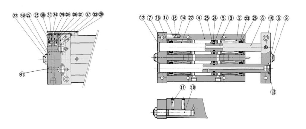
7 Slide Unit/Double Rod Type Series CX Construction/Parts List, Seal List e q!6 t!0 u y r w! i!9!8 CXN, 5!0 w q o r i yu!3!7 Parts List No Description Material Note Rod cover Housing Piston Piston rod Plate Lock nut Set screw (For fixing rods) Pin Retaining ring Plug (M-5P) Magnet Ball fixing screw Spring Type CR retaining ring Round type R retaining ring Aluminum bearing alloy Aluminum alloy Hard anodized Aluminum alloy Carbon steel piping for machine constructions Hard chrome plated Aluminum alloy Anodized Carbon steel Chromium steel Chromium steel Carbon steel Quenched Carbon tool steel Brass Chromium steel Stainless steel Carbon tool steel Carbon tool steel Parts List No. Description Material Note Steel ball Socket Gasket Rod seal Piston seal Piston gasket Cylinder tube gasket High carbon chrome bearing steel Brass Heat treated Electroless nickel plated Replacement Parts: Seal Kit CXN CXN CXN5 Kit no. CXN-PS CXN-PS CXN5-PS Contents A @3 listed above Seal @3. Order the seal kit, based on each bore size. (The piston is not replaceable.) Since the seal kit does not include a grease pack, order it separately. Grease pack part no.: GR-S-0 ( g) CX 467

")


 Note ) The dimensions show D-E7 A and D-E80A.")
8 Series CX ø Basic Type: CXN Strokes: 5 to 0 4 x ø6.5 counterbore depth x ø3.3 through Socket x M5 x 0.8 x M4 x 0.7 thread depth 8 x ø4 4 x M4 x 0.7 Bottom through-hole ø3.3 through depth 5 Socket connection port ( positions of hexagon socket head cap screws) x M5 x 0.8 Plug (M-5P) x M8 x.0 Max. 7 x x M4 x 0.7 thread depth 8 x x ø4 depth 5 x ø6.5 counterbore depth 3.3 CXN-5 CXN-50 CXN-75 CXN-0 x ø3.3 through Max. ZZ F G L P Q R S SS Max. ZZ With shock absorber Z With adjusting bolt ZZ Max. 3 With shock absorber ZZ Housing mounting style with auto switch Plate mounting style with auto switch CDBXN Stroke CDPXN Stroke Magnet mounting block Auto switch Auto switch Plugs ( pcs.) Note ) The dimensions show D-E7 A and D-E80A. 468 Note ) The dimensions show D-A7 and D-A8. D-A7, D-A8 D-F7, D-J79, D-J79W, D-F7PW, D-F7 V D-F7LF 4 30 Hv Note ) For only 5 strokes, two magnets for auto switches are installed in the housing.


 The")
 For only 5")

9 Slide Unit/Double Rod Type Series CX ø Basic Type: CX Strokes: 5 to 00 (ø5h7 hole pitch) x x ø8 counterbore depth 4 x x ø4.3 through x x M5 x 0.8 Hexagon socket head cap plug 4 x M5 x 0.8 thread depth x ø5h7 0 depth 6 x M5 x 0.8 x M8 x.0 4 x ø4. through 3 x M5 x 0.8 thread depth x ø5h7 Depth x ø7.6 counterbore depth 4.4 Max. ZZ Max. 3 With shock absorber Max. ZZ CX -5 CX -50 CX -75 CX -0 CX -5 CX -0 CX -75 CX -00 F L P Q S SS Z With adjusting bolt ZZ With shock absorber ZZ Housing mounting style with auto switch CDBX Stroke Auto switch Note ) The dimensions show D-A7 and D-A8. D-A7, D-A8 D-F7, D-J79, D-J79W, D-F7PW, D-F7 V D-F7LF Magnet mounting block 4 30 Hs Note ) For only 5 strokes, two magnets for auto switches are installed to the magnet mounting block. Plate mounting style with auto switch CDPX Stroke Auto switch Plugs ( pcs.) Note ) The dimensions show D-A7 and D-A8. D-A7, D-A8 D-F7, D-J79, D-J79W, D-F7PW, D-F7 V D-F7LF 4 30 Hv Note ) For only 5 strokes, two magnets for auto switches are installed in the housing. 469 CX
 / 8 Plug Rc (PT) / 8 4 x M6 x.0 thread depth x ø6h7 0 depth 8 Dimensions at 5 strokes x Rc (PT) / 8 x M x.")


 For only 5 strokes, two magnets for auto switches are")
10 Series CX ø5 Basic Type: CX 5 Strokes: 5 to 00 (ø6 H7 hole pitch) x x ø9.5 counterbore depth 5 x x ø5. through x x Rc (PT) / 8 Plug Rc (PT) / 8 4 x M6 x.0 thread depth x ø6h7 0 depth 8 Dimensions at 5 strokes x Rc (PT) / 8 x M x.0 4 x ø5.5 through 3 x M6 x.0 thread depth RB06 x ø6h7 0 Depth 8 4 x ø9.5 counterbore depth 5.5 Max. ZZ CX 5-5 CX 5-50 CX 5-75 CX 5-0 CX 5-5 CX 5-0 CX 5-75 CX 5-00 F L P Q S SS Max. ZZ With shock absorber Z Max. 3 With adjusting bolt ZZ With shock absorber ZZ Housing mounting style with auto switch Plate mounting style with auto switch CDBX 5 Stroke CDPX 5 Stroke Auto switch Magnet mounting block Auto switch Note ) The dimensions show D-A7 and D-A8. D-A7, D-A8 D-F7, D-J79, D-J79W, D-F7PW, D-F7 V D-F7LF Hs Note ) For only 5 strokes, two magnets for auto switches are installed to the magnet mounting block. Plugs ( pcs.) Rc (PT) / 8 Note ) The dimensions show D-A7 and D-A8. D-A7, D-A8 D-F7, D-J79, D-J79W, D-F7PW, D-F7 V D-F7LF 4 30 Hv Note ) For only 5 strokes, two magnets for auto switches are installed in the housing.
11 Slide Unit/Double Rod Type Series CX Operating Range D-A7 /A80 D-A7 H/A80H D-A73C/A80C D-E7 A/E80A D-F7 /J79 D-F7 V/J79C D-F7 W/F7 WV D-F7BAL/F7BAVL D-F79F/F7NTL Housing mounting Plate mounting Housing mounting Housing mounting Plate mounting Applicable cylinder size Since the operating range is provided as a guideline including hysteresis, it cannot be guaranteed (assuming approximately ±30% dispersion). It may vary substantially depending on an ambient environment. Besides the models listed in How to Order, the following auto switches are applicable. Refer to pages 79 to 87 for the detailed specifications. Electrical entry Auto switch type Features (Fetching direction) Applicable cylinder size Housing mounting Plate mounting Solid state D-F7NTL Grommet (In-line) With timer ø, ø5 ø, ø, ø5 With pre-wired connector is also available for D-F7NTL type. For details, refer to pages 784 and 785. It is impossible to mount solid state auto switches to the housing mounting ø. CX 47
12 Series M/L Prior to Use. Changing from the non-auto switch specifications to the auto switch specifications. Changing mounting style of the auto switch specifications Series M L M. In Series L, to change from the specification without auto switch to the plate mounting style with auto switch or to the housing mounting style with auto switch, refer to tables (3) and (4) before ordering. Without auto switch: Plate mounting style with auto switch: Housing mounting style with auto switch: M L CDPXW CDBXW M L M L S M Table (3) Table (4) M. In Series L, to change from the plate mounting style with an auto switch to the housing mounting style with an auto switch or vice versa, refer to tables (3) and (4) before ordering. Plate mounting style M with auto switch: L Table (3) CDPXW S Housing mounting style with auto switch: CDBXW M L M Table (4) Table (3) Plate Mounting Style with Auto Switch M (CDPXW L - ) Component Parts for Mounting Switches and No. of Component Parts ø ø6 ø0 ø5 ø3 Component parts Material Assembly model no. for mounting switch (3) M M M M M CDPXW L CDPXW L CDPXW L CDPXW L CDPXW L S- 6S- 0S- 5S- 3S- Switch mounting block Aluminum alloy Block mounting screw Chrome steel/ Switch mounting screw Chrome steel/ Hexagon nut Carbon steel/ Magnet () () Socket Brass/Electroless nickel plated Plug (M-5P) Brass/Electroless nickel plated Note ) mark indicates strokes. Note ) In the case of ø, the 5 mm stroke has two magnets that are bonded in the holes on the side of the housing. Those with strokes of 50 mm to 0 mm have one magnet. Those with other bore sizes have a built-in magnet in their housings. Note 3) For the assembly model no. for mounting switch, order with CDPXWM - for Series M and order with CDPXWL - for Series L respectively. Table (4) Housing Mounting Style with Auto Switch M (CDBXW L - ) Component Parts for Mounting Switches and No. of Component Parts ø ø6 ø0 ø5 ø3 Component parts Material Assembly model no. for mounting switch M M M M M CDBXW L CDBXW L CDBXW L CDBXW L CDBXW L M- 6M- 0M- 5M- 3M- Magnet mounting block assembly Aluminum alloy Switch mounting rail Aluminum alloy Spacer Aluminum alloy/anodized Block mounting screw Chrome steel/ Screw for mounting rail Chrome steel/ Switch mounting screw Chrome steel/ Hexagon nut Carbon steel/ Hexagon socket head plug Chrome steel/ Note ) mark indicates strokes. M M M Note ) In the case of ø, CDPXW L - can NOT be changed to CDBXW L -. ( L - can be changed to M CDBXWL- ) Note 3) For the assembly model no. for mounting switch, order with CDBXWM - for Series M and order with CDBXWL - for Series L respectively. 47
13 Slide Unit: Built-in Shock Absorber Slide Bearing Type Series M ø, ø6, ø0, ø5, ø3 How to Order M 6 0 Port thread type Nil M thread ø to ø0 Rc /8 TN TF NPT /8 G /8 ø5, ø3 With auto switch C DB XWM 6 Cylinder with auto switch Symbol DB Specifications/Mounting With auto switch/ Housing mounting Bearing type DP With auto switch/ M Slide bearing Plate mounting Bore size/stroke ø ø6 ø0 ø5 ø3 (5), 50, 75, 0 (5), 50, 75, 0, 5, 0, 75, 00 (5), 50, 75, 0, 5, 0, 75, 00 (5), 50, 75, 0, 5, 0, 75, 00 (5), (50), 75, 0, 5, 0, 75, 00 Note) For the strokes indicated in the parentheses of the ø, ø6 and ø5, shock absorbers are to be mounted on both sides of the plate. For the strokes indicated in the parentheses of the ø0 and ø3, a shock absorber is to be mounted on single side of the plate. Note) For the strokes other than those indicated above, refer to page 474. Note3) For ø6, ø0 and ø5, strokes up to 300, and for ø3, strokes up to 50 are available as made-to-order. (-XB) 0 J79W End lock R Nil Auto switch Nil Made to Order Refer to page 474 for the Made to Order specifications. Number of auto switches Nil pcs. S pc. n n pcs. For the applicable auto switch model, refer to the table below. End lock None Without auto switch Built-in Magnet Cylinder If a built-in magnet cylinder without an auto switch is required, there is no need to enter the symbol for the auto switch. (Example) CDPXWM0-0 Applicable Auto Switch/Refer to pages 79 to 87 for further information on auto switches. Type Special function Electrical entry Reed switch Solid state switch Diagnostic indication (-color indication) Water resistant (-color indication) With diagnostic output (-color indication) Grommet Connector Grommet Grommet Connector Grommet Indicator light Yes Yes Yes No No No Yes Wiring (Output) 3-wire (NPN) 3-wire (PNP) -wire 3-wire (NPN) 3-wire (PNP) -wire 4-wire (NPN) 3-wire (NPN equivalent) -wire 3-wire (NPN equivalent) -wire 4 V 4 V 4 V Load voltage DC 5 V, V V 5 V, V V 5 V, V 5 V V 5 V, V V 5 V, V 5 V V 5 V, V AC 00 V 0 V 0 V or less 4 V or less 0 V 0 V or less Rail mounting Perpendicular F7NV F7PV F7BV J79C F7NWV F7BWV F7BAV A7 A73 A80 A73C A80C In-line F79 F7P J79 F79W F7PW J79W F7BA F79F A76H A7H A73H A80H E76A E73A E80A Applicable cylinder size Housing mounting ø6 ø0 ø5 ø3 ø6 ø0 ø5 ø3 ø Plate mounting ø ø6 ø0 ø5 ø3 ø ø6 ø0 ø5 ø3 Lead wire length (m) 0.5 (Nil) 3 (L) 5 (Z) None (N) Pre-wired connector Applicable load Lead wire length symbols: 0.5 m Nil (Example) F79W Solid state auto switches marked with are produced upon receipt of order. 3 m L (Example) F79WL It is impossible to mount solid state switches to the housing mounting ø. 5 m Z (Example) F79WZ None N (Example) J79CN Since there are other applicable auto switches than listed, refer to page 57 for details. For details about auto switches with pre-wired connector, refer to pages 784 and 785. Auto switches are shipped together (not assembled). IC circuit IC circuit IC circuit IC circuit IC circuit IC circuit IC circuit Relay, PLC Relay, PLC Relay, PLC 473 CX
14 Series M Built-in shock absorber This is a built-in shock absorber style in which the shock absorber is enclosed in the housing. Compared to Series CX with shock absorber, this style achieves space savings in the longitudinal direction (except 5 mm stroke). Dramatically reduced installation labor The machining precision required for positioning during the installation of the cylinder has been reduced through the adoption of a special pin hole machining process, thus decreasing the amount of labor involved in adjustment. Provided with an end lock mechanism An end lock is also available, which maintains the cylinder s original position even if the air supply is interrupted. Symbol Specifications XB Long stroke type XB3 Low speed cylinder (5 to 50 mm/s) XC Fluororubber seal X46 Hollow piston rod X38 Adjustable stroke X68 Helical insert thread X69 built-in magnets Standard Stroke Made to Order Specifications (For details, refer to pages 85 to 0.) Standard stroke () ( ) () ( ) () ( ) () ( ) Specifications Type Fluid Proof pressure Max. operating pressure Min. operating pressure M/6 M0/5/3 0. MPa 0. MPa Ambient & fluid temperature to 60 C (No freezing) Piston speed (Non-lube) 30 to 500 mm/s Cushion Stroke adjustable range Standard stroke: ± mm Accessory (Option) Straight knock pin ( pcs.), (-X38) -X38 has a stroke adjustable range of mm on one side. M kg ± N M6 4 kg ± N M0 5 kg ± N M5 6 kg ± N M3 kg ± N RB0805-X55 RB0805 RB06-X55 RB06 RB4-X55 RB to to Extended Spring force (N) Retracted Mass (g) 5 65 Note ) -X55 is an exclusive shock absorber installed in the housing, and is the screw not attached specification of the outer part of the outer tube. The shock absorber plate mounting style of 5 and 50 strokes have the screw attached specification. Note ) It denotes the values at the maximum energy absorption per one cycle. Therefore, the operating frequency can be increased according to the energy absorption. The shock absorber service life is different from that of the cylinder depending on the operating conditions. Refer to the Series RB Specific Product Precautions for the replacement period. Theoretical Output Rod size Piston area (mm ) Operating pressure (MPa) Non-lube Air.5 MPa.0 MPa Maximum Load Mass/Non-rotating Accuracy/Maximum Holding Force Maximum load mass Non-rotating accuracy Deflection of a piston ( rod is not included. ) Maximum holding force End lock model ( ) Place the center of gravity of the load and center of the slide unit close during operation. If they are placed far apart from each other, please consult with SMC. Shock Absorber Specifications () Applicable slide unit Maximum energy absorption (J) Stroke absorption Max. collision speed (m/sec) Max. operating frequency (cycle/min) () Max. allowable thrust (N) Ambient temperature range ( C) Note) Theoretical output (N) = Pressure (MPa) x Piston area (mm ) (N) M/6- M0/5- M3- M- M6- M0- M5- M3- M- M6- M0- M5- M3- () () ( ) ( ) Note ) The strokes marked with ( ) has an absorber of double side plate mounting style. Note ) The strokes marked with ( ) has an absorber of single side plate mounting style. 474
15 Slide Unit: Built-in Shock Absorber Slide Bearing Type Series M Mass (kg) M M6 M0 M5 M Stroke Additional Mass with End Lock (M - R) Applicable model Additional mass M 0.08 M6 0.4 M0 0. M5 0.0 M Operating Direction with Different Pressure Ports (kg) Accessory Straight Knock Pin (Option) Operating direction of housing when the plate is fixed With end lock (M- R) Operating direction of housing when the plate is fixed Standard side of housing (Mounting side) Left Right Operating direction of the housing Pressure port A B C D E F Operating direction Right Left Left Right Left Right There are 9 possible reciprocating piping methods. Pressure port Standard side of housing (Mounting side) Left Right Operating direction of the housing A B Operating direction Right Left Left Right Right Left Left Right There are 6 possible reciprocating piping methods. C D E F G H M M6 M0 M5 M3 L 0 ød Manufactured by Misumi Trading Ltd. MS4- MS5- MS6- MS6- MS8-0 Deflection of Piston Rod by Center Loading (Reference) When center loading is added to the center of the housing M M6 M0 M5 M3 Load (N) Stroke When center loading is added to the center of the plate Deflection width Stroke Load (N) M M M M M Note) The values denote the total width of the deflections in the upward/downward direction. CX 475


16 Series M Construction: ø, ø6, ø5 M With end lock M6, 5 ø6/with end lock ø5/with end lock "%$
17 Slide Unit: Built-in Shock Absorber Slide Bearing Type Series M Construction: ø, ø6, ø5 Component Parts No Description Rod cover Housing Piston Piston rod Plate Lock nut Set screw (For fixing rods) Set screw (For fixing shock absorbers) Retaining ring Plug Magnet Set screw for seal Spring Type CR retaining ring Round type R retaining ring Socket Gasket Rod seal Piston seal Piston gasket Cylinder tube gasket Material Aluminum bearing alloy Aluminum alloy Aluminum alloy Carbon steel piping for machine constructions Aluminum alloy Carbon steel Chromium steel Chromium steel Stainless steel Carbon tool steel Brass Chromium steel Stainless steel Carbon tool steel Carbon tool steel Brass Note Hard anodized Chromated Hard chrome plated Hard anodized ø5 (RB0805-X55 or RB06-X55) Electroless nickel plated Component Parts: With End Lock No. Description 4 Locking body 5 Lock finger 6 Lock piston 7 Rod cover 8 Return spring 9 30 Body gasket 3 Rod seal 3 Piston seal 33 Steel ball 34 Steel ball 35 O-ring 36 Round type R retaining ring 37 Lock nut 38 Plug Replacement Parts: Seal Kit End Lock Material Note Aluminum alloy Hard anodized Alloy tool steel after quenched Carbon tool steel Electroless nickel plated after quenched Aluminum alloy Spring steel Zinc chromated Chromium steel High carbon chrome bearing steel High carbon chrome bearing steel Carbon tool steel Carbon steel Chromium steel Kit no. Contents M M6 M5 MR-PS M6R-PS M5R-PS Set of nos. above Grease pack part no.: GR-S-0 ( g) Replacement Parts: Seal Kit Cylinder Body Kit no. Contents M M6 M5 M-PS M6-PS M5-PS Set of nos. above Grease pack part no.: GR-S-0 ( g) CX 477

18 Series M Construction: ø0, ø3 With end lock Component Parts No Description Rod cover Housing Piston Piston rod Plate Hexagon socket head set screw Retaining ring Magnet Spring Type CR retaining ring Round type R retaining ring Hexagon socket head set screw Hexagon socket head plug Hexagon socket head set screw Piston seal Rod seal Cylinder tube gasket Piston gasket Material Aluminum bearing alloy Aluminum alloy Aluminum alloy Carbon steel for machines Aluminum alloy Chromium steel Chromium steel Tool steel Stainless steel Carbon tool steel Carbon tool steel Chromium steel Chromium steel Chromium steel Replacement Parts: Seal Kit Cylinder Body Note Hard anodized Chromated Hard chrome plated Hard anodized RB06-X55, RB4-X55 Kit no. Contents M0 M0-PS Set of nos. above M3 M3-PS Component Parts: With End Lock No Note) Note) 3 4 Description Locking body Lock finger Lock piston Rod cover Steel ball Steel ball Round type R retaining ring Return spring Plug (50), 75 to (00) ST (5), 50 ST (50), 75 to (00) ST (5), 50 ST Body gasket Rod seal Piston seal O-ring Hexagon socket head set screw Hexagon nut Replacement Parts: Seal Kit End Lock Material Aluminum alloy Alloy tool steel Tool steel Aluminum bearing alloy High carbon chrome bearing steel High carbon chrome bearing steel Carbon tool steel Spring steel Chromium steel Chromium steel Carbon steel Chromium steel Kit no. Contents M0 M0R-PS Set of nos. above M3 M3R-PS Note Hard anodized after quenched Electroless nickel plated after quenched Zinc chromated RB06 or RB4 Note) The strokes indicated in the parentheses are of M0, and M3 includes the strokes indicated in the parentheses. Grease pack part no.: GR-S-0 ( g) Grease pack part no.: GR-S-0 ( g) 478
19 Slide Unit: Built-in Shock Absorber Slide Bearing Type Series M ø Basic Type: M- Stroke/50 to 0 Max. ZZ x x ø3.3 through x x ø6.5 counterbore depth 3. x M8 x.0 (ø4h7 hole pitch) 4H7 0 depth 3 ø4h7 0 depth 6 4 positions of set screws for fixing shock absorber (M4) x M4 x 0.7 socket connection port ( positions of hexagon socket head cap plug) 4 x M4 x 0.7 thread depth 6 Socket x M5 x 0.8 x M5 x 0.8 plug (M-5P) (Port on the housing side) Max. 8 x x ø4h7 0 depth 5 4 x ø3. through 4 x ø6.5 counterbore depth 3.3 CX x x M4 x 0.7 thread depth 8 x RB0805-X55 Note) For 5 stroke, the shock absorber is mounted on a plate. For dimensions of the 5 stroke, refer to page 480. M-50 M-75 M-0 F L P Q S 5 77 SS Z ZZ
20 Series M ø Basic Type: M- 5 stroke Max. 76 x x ø3.3 through x x ø6.5 counterbore depth 3. (ø4h7 hole pitch) 4H7 0 depth 3 x M4 x 0.7 socket connection port ø4h7 0 depth 6 ( positions of hexagon socket head cap plug) 4 x M4 x 0.7 thread depth 6 Socket x M5 x 0.8 x M5 x 0.8 plug (M-5P) (Port on the housing side) 4 x ø3. through 4 x ø6.5 counterbore depth 3.3 x x ø4h7 0 depth 5 x M8 x.0 RB0805 x x M4 x 0.7 thread depth 8 480
21 Slide Unit: Built-in Shock Absorber Slide Bearing Type Series M ø With End Lock: M- Stroke/50 to 0 R x x M4 x 0.7 thread depth 8 x x ø4h7 0 depth 5 x M8 x.0 Max. ZZ x RB0805-X55 x M5 x 0.8 hexagon socket head cap plug Max. 9 4 x ø3. through Socket 4 x ø6.5 counterbore depth 3.3 x M5 x 0.8 x M5 x 0.8 plug (M-5P) Max. 8 End lock mechanism ø4h7 0 depth 6 x x ø3.3 through x x ø6.5 counterbore depth 3. x M5 x 0.8 hexagon socket head cap plug 4 x M4 x 0.7 thread depth 6 4 positions for set screws for fixing shock absorbers (M4) M-50R M-75R M-0R ZZ Housing mounting style with auto switch Plate mounting style with auto switch CDBXWM- Stroke, CDBXWM- Stroke R CDPXWM- Stroke, CDPXWM- Stroke R Auto switch Magnet mounting block Auto switch Note ) The dimensions show D-E7 A and D-E80A. Note ) For 5 stroke, the shock absorber is mounted on a single side of the plate. For dimensions of the 5 stroke, refer to page 48. Note ) The dimensions show D-A7 and D-A8. D-A7, D-A80 D-F7, D-J79, D-J79W, D-F7 W, D-F7 V, D-F7 WV, D-F7BAV 4 Hv Note ) For 5 stroke, the shock absorber is mounted on a single side of the plate. For dimensions of 5 stroke, refer to page CX
22 Series M ø With End Lock: M- 5 Stroke R xxm4x0.7thread depth 8 xx 4H7 0 depth 5 M8 x.0 Max ±0.0 x M5 x 0.8 hexagon socket head cap plug 4 x 3. through 4 x 6.5 counterbore depth 3.3 Socket xm5x0.8 Max. 9 x M5 x 0.8 plug (M-5P) x RB0805 shock absorber (Single housing installed) End lock mechanism 4H7 0 depth 6 x x 3.3 through x x 6.5 counterbore depth 3. positions for set screws for fixing shock absorbers (M4) x M5 x 0.8 hexagon socket head cap plug 4 x M4 x 0.7 thread depth 6 Housing mounting style with auto switch CDBXWM-5, CDBXWM-5R Plate mounting style with auto switch CDPXWM-5, CDPXWM-5R Auto switch Magnet mounting block Auto switch 48 Note ) The dimensions show D-E7 A and D-E80A. Note ) magnets for auto switches are equipped to the magnet mounting block. Note ) The dimensions show D-A7 and D-A8. D-A7, D-A80 D-F7, D-J79, D-J79W, D-F7 W, D-F7 V, D-F7 WV, D-F7BAV 4 Hv Note ) magnets for auto switches are installed in the housing.
23 Slide Unit: Built-in Shock Absorber Slide Bearing Type Series M ø6 Basic Type: M6- Stroke/50 to 00 Max. ZZ x x ø4.3 through x x ø8 counterbore depth 4.5 (ø5h7 hole pitch) x M8 x.0 5H7 0 depth 3 ø5h7 0 depth 6 4 positions for set screws for fixing shock absorbers (M4) 4 x M5 x 0.8 thread depth x x M5 x 0.8 (Hexagon socket head cap plug) x M5 x x ø4.3 through 4 x ø8 counterbore depth 4.5 x x M5 x 0.8 Thread depth x RB0805-X55 x x ø5h7 0 depth 6 CX Note) For 5 stroke, the shock absorber is mounted on a plate. Refer to page 484 for the dimensions of the 5 stroke. M6-50 M6-75 M6-0 M6-5 M6-0 M6-75 M6-00 F L P Q S SS Z ZZ
24 Series M ø6 Basic Type: M6-5 stroke Max. 84 x x ø4.3 through x x ø8 counterbore depth (ø5h7 hole pitch) 5H7 0 depth 3 ø5h7 0 depth 6 4 x M5 x 0.8 thread depth x x M5 x 0.8 (Hexagon socket head cap plug) x M5 x 0.8 Max. 9 4 x ø4.3 through 4 x ø8 counterbore depth 4.5 x x M5 x 0.8 Thread depth x M8 x.0 RB0805 x x ø5h7 0 depth 6 484
25 Slide Unit: Built-in Shock Absorber Slide Bearing Type Series M ø6 With End Lock: M6- Stroke/50 to 00 R x x M5 x 0.8 thread depth x x ø5h7 0 depth 6 x M8 x.0 Max. ZZ x RB0805-X55 x M5 x 0.8 x M5 x 0.8 Hexagon socket head cap plug Max. 6 4 x ø4.3 through 4 x ø8 counterbore depth 4.5 x M5 x 0.8 plug (M-5P) Max. 6 End lock mechanism ø5h7 0 depth 6 x x ø4.3 through x x ø8 counterbore depth 4.5 x M5 x 0.8 hexagon socket head cap plug 4 positions for set screws for fixing shock absorbers (M4) 4 x M5 x 0.8 thread depth M6-50R M6-75R M6-0R M6-5R M6-0R M6-75R M6-00R ZZ Housing mounting style with auto switch Plate mounting style with auto switch CDBXWM6- Stroke, CDBXWM6- Stroke R CDPXWM6- Stroke, CDPXWM6- Stroke R Auto switch Magnet mounting block Auto switch Note ) The dimensions show D-A7 and D-A8. D-A7, D-A80 D-F7, D-J79, D-J79W, D-F7 W, D-F7 V, D-F7 WV, D-F7BAV D-F7LF 4 30 Hs Note ) For 5 stroke, the shock absorber is mounted on a single side of the plate. For dimensions of 5 stroke, refer to page 486. Note ) The dimensions show D-A7 and D-A8. D-A7, D-A80 D-F7, D-J79, D-J79W, D-F7 W, D-F7 V, D-F7 WV, D-F7BAV 4 Hv Note ) For 5 stroke, the shock absorber is mounted on a single side of the plate. For dimensions of 5 stroke, refer to page CX
26 Series M ø6 With End Lock: M6-5 stroke R x x M5 x 0.8 thread depth xxø5h7 0 depth 6 M8x Max. 84 x M5 x 0.8 xm5x0.8 Hexagon socket head cap plug 4 x ø4.3 through 4 x ø8 counterbore depth 4.5 x M5 x 0.8 plug (M-5P) M8 x.0 x RB0805 shock absorber (Single housing installed) End lock mechanism ø5h7 0 depth 6 Max. 9 xxø4.3 through xxø8counterbore depth 4.5 x M5 x 0.8 hexagon socket head cap plug 4 x M5 x 0.8 thread depth positions for set screws for fixing shock absorbers (M4) Housing mounting style with auto switch CDBXWM6-5, CDBXWM6-5R Plate mounting style with auto switch CDPXWM6-5, CDPXWM6-5R Auto switch Magnet mounting block Auto switch Note ) The dimensions show D-A7 and D-A8. Hs D-A7, D-A80 D-F7, D-J79, D-J79W, D-F7 W, D-F7 V, D-F7 WV, D-F7BAV D-F7LF 4 30 Note ) magnets for auto switches are equipped to the magnet mounting block. Note ) The dimensions show D-A7 and D-A8. D-A7, D-A80 D-F7, D-J79, D-J79W, D-F7 W, D-F7 V, D-F7 WV, D-F7BAV 4 Hv Note ) magnets for auto switches are installed in the housing. 486
27 Slide Unit: Built-in Shock Absorber Slide Bearing Type Series M ø0 Basic Type: M0- Stroke/50 to 00 x x ø5. through x x ø9.5 counterbore depth 5 (ø6h7 hole pitch) 6H7 depth 4 0 x M x.0 x 4 x M5 x 0.8 thread through From the opposite side x 4 x ø7.5 counterbore depth 4.5 positions for set screws for fixing adjusting bolt (M5) 4 x M6 x.0 thread depth 9 ø6h7 0 depth 8 4 positions for set screws for fixing shock absorbers x x M5 x 0.8 (Hexagon socket head cap plug) x M5 x 0.8 x M4 x 0.7 thread depth 5 x x M6 x.0 thread depth x x ø6h7 0 depth 8 4 x ø5.5 through 4 x ø9.5 counterbore depth 5.5 CX x RB06-X55 () M0-50 M0-75 M0-0 M0-5 M0-0 M0-75 M0-00 F L P Q S SS Z ZZ Note) For 5 stroke, the shock absorber is mounted on a single side of the plate. For dimensions of 5 stroke, refer to page
28 Series M ø0 Basic Type: M0-5 stroke Max. 67 x x ø5. through x x ø9.5 counterbore depth 5 Set screw for fixing adjusting bolt (M5) (ø6h7 hole pitch) 6H7 depth 4 0 x 4 x M5 x 0.8 thread through From the opposite side x 4 x ø7.5 counterbore depth 4.5 M x.0 4 x M6 x.0 thread depth 9 ø6h7 0 depth 8 positions for set screws for fixing shock absorbers x x M5 x 0.8 (Hexagon socket head cap plug) x M5 x 0.8 x M4 x 0.7 thread depth 5 x x M6 x.0 thread depth x x ø6h7 0 thread depth 8 4 x ø5.5 through 4 x ø9.5 counterbore depth 5.5 Max. 33 x RB06 () M x.0 (Single housing installed) 488
29 Slide Unit: Built-in Shock Absorber Slide Bearing Type Series M ø0 With End Lock: M0- Stroke/50 to 00 R ø depth (An adjusting bolt M x.0 x 4 l to the plate port) x x M6 x.0 thread depth 8 x x ø6h7 0 depth 8 4 x M5 x 0.8 thread through From opposite side 4 x ø7.5 counterbore depth 4.5 positions for set screws for fixing adjusting bolt (M5) 45 x M5 x 0.8 hexagon socket head cap plug 4 x ø5.5 through 4 x ø9.5 counterbore depth 5.5 x M x.0 x M5 x 0.8 x M5 x 0.8 Hexagon socket head cap plug End lock mechanism (ø6h7 hole pitch) x x ø5. through x x ø9.5 counterbore depth 5 4 x M6 x.0 thread depth 9 4 positions for set screws for fixing shock absorbers Note ) The dimensions show D-A7 and D-A8. D-A7, D-A80 D-F7, D-J79, D-J79W, D-F7 W, D-F7 V, D-F7 WV, D-F7BAV D-F7LF 4 30 Hs Note ) For 5 stroke, the shock absorber is mounted on a single side of the plate. For dimensions of 5 stroke, refer to page 4. Thread depth 4 x M5 x 0.8 hexagon socket head cap plug ø6h7 0 depth 8 x RB06- X55 M0-50R M0-75R M0-0R M0-5R M0-0R M0-75R M0-00R F L P Q S SS Z ZZ Housing mounting style with auto switch Plate mounting style with auto switch CDBXWM0- Stroke, CDBXWM0- Stroke R CDPXWM0- Stroke, CDPXWM0- Stroke R Auto switch Magnet mounting block Auto switch Note ) The dimensions show D-A7 and D-A8. D-A7, D-A80 D-F7, D-J79, D-J79W, D-F7 W, D-F7 V, D-F7 WV, D-F7BAV 4 Hv Note ) For 5 stroke, the shock absorber is mounted on a single side of the plate. For dimensions of 5 stroke, refer to page CX
30 Series M ø0 With End Lock: M0-5 stroke R Max. 67 M x.0 RB06 x x ø6h7 0 depth 8 4 x M5 x 0.8 thread through From opposite side 4 x ø7.5 counterbore depth 4.5 Set screw for fixing adjusting bolt (M5) x M5 x 0.8 hexagon socket head cap plug 4 x ø5.5 through 4 x ø9.5 counterbore depth 5.5 M x.0 x x M6 x.0 thread depth x M5 x 0.8 x M5 x 0.8 Hexagon socket head cap plug End lock mechanism Max. x x ø5. through x x ø9.5 counterbore depth 5 5 ± x M6 x.0 thread depth 9 (ø6h7 hole pitch) 6H7 0 depth 4 positions for set screws for fixing shock absorbers x RB06-X55 ø6h7 0 depth 8 x M5 x 0.8 hexagon socket head cap plug Housing mounting style with auto switch CDBXWM0-5, CDBXWM0-5R Auto switch Magnet mounting block Plate mounting style with auto switch CDPXWM0-5, CDPXWM0-5R Auto switch 4 Note ) The dimensions show D-A7 and D-A8. D-A7, D-A80 D-F7, D-J79, D-J79W, D-F7 W, D-F7 V, D-F7 WV, D-F7BAV D-F7LF 4 30 Hs Note ) magnets for auto switches are equipped to the magnet mounting block. Note ) The dimensions show D-A7 and D-A8. D-A7, D-A80 D-F7, D-J79, D-J79W, D-F7 W, D-F7 V, D-F7 WV, D-F7BAV 4 Hv Note ) magnets for auto switches are installed in the housing.
31 Slide Unit: Built-in Shock Absorber Slide Bearing Type Series M ø5 Basic Type: M5- Stroke/50 to 00 x x ø5. through x x ø9.5 counterbore depth 5 Max. ZZ (ø6h7 hole pitch) depth 4 4 x M6 x.0 thread depth ø6h7 0 depth 8 4 positions for set screws for fixing shock absorbers (M5) x x Rc /8 Plug (R /8) x Rc /8 x x M6 x.0 thread depth x x ø6h7 0 depth 8 4 x ø5.5 through 4 x ø9.5 counterbore depth 5.5 Max. 6 x M x.0 50 x RB06-X55 CX Note) For 5 stroke, the shock absorber is mounted on a plate. For dimensions of 5 stroke, refer to page 49. M5-50 M5-75 M5-0 M5-5 M5-0 M5-75 M5-00 F L P Q S SS Z ZZ
32 Series M ø5 Basic Type: M5-5 stroke Max. 03 x x ø5. through x x ø9.5 counterbore depth 5 5 (ø6h7 hole pitch) 6H7 0 depth 4 4 x M6 x.0 thread depth ø6h7 0 depth 8 x x Rc /8 Plug (R /8) x Rc /8 x x M6 x.0 thread depth x x ø6h7 0 depth 8 4 x ø5.5 through 4 x ø9.5 counterbore depth 5.5 x M x.0 RB06 50 Max. 3 49
33 Slide Unit: Built-in Shock Absorber Slide Bearing Type Series M ø5 With End Lock: M5- Stroke/50 to 00 R x x M6 x.0 thread depth x x ø6h7 0 depth 8 x M x.0 Max. ZZ 50 x Rc /8 Plug (R /8) Max. 6 4 x ø5.5 through 4 x ø9.5 counterbore depth 5.5 x Rc /8 Plug (R /8) x Rc /8 Max. 6 End lock mechanism x RB06-X55 ø6h7 0 depth 8 x x ø5. through x x ø9.5 counterbore depth 5 x Rc /8 Plug (R /8) 4 x M6 x.0 thread depth 4 positions for set screws for fixing shock absorbers (M5) M5-50R M5-75R M5-0R M5-5R M5-0R M5-75R M5-00R ZZ Housing mounting style with auto switch CDBXWM5- Stroke, CDBXWM5- Stroke R Plate mounting style with auto switch CDPXWM5- Stroke, CDPXWM5- Stroke R Auto switch Magnet mounting block Auto switch Note ) The dimensions show D-A7 and D-A8. Note ) The dimensions show D-A7 and D-A8. D-A7, D-A80 Hs D-A7, D-A80 Hv.5 D-F7, D-J79, D-J79W, D-F7 W, D-F7, D-J79, D-J79W, D-F7 W, D-F7 V, D-F7 WV, D-F7BAV D-F7LF 4 30 D-F7 V, D-F7 WV, D-F7BAV Note ) For 5 stroke, the shock absorber is mounted on a single side of the plate. For dimensions of 5 stroke, refer to page 494. Note ) For 5 stroke, the shock absorber is mounted on a single side of the plate. For dimensions of 5 stroke, refer to page CX
34 Series M ø5 With End Lock: M5-5 stroke R x x M6 x.0 thread depth x x ø6h7 0 depth 8 Max. 0 x M x.0 x Rc /8 Plug (R /8) Max. 6 4 x ø5.5 through 4 x ø9.5 counterbore depth 5.5 x Rc /8 Plug (R /8) x Rc /8 x RB06 shock absorber (Single housing installed) End lock mechanism ø6h7 0 depth 8 Max. 3 x x ø5. through x x ø9.5 counterbore depth 5 positions for set screws for fixing shock absorbers (M5) 4 x M6 x.0 thread depth x Rc /8 Plug (R /8) Housing mounting style with auto switch CDBXWM5-5, CDBXWM5-5R Plate mounting style with auto switch CDPXWM5-5, CDPXWM5-5R Auto switch Magnet mounting block Auto switch Note ) The dimensions show D-A7 and D-A8. Note ) The dimensions show D-A7 and D-A8. D-A7, D-A80 D-F7, D-J79, D-J79W, D-F7 W, D-F7 V, D-F7 WV, D-F7BAV D-F7LF 4 30 Hs Note ) magnets for auto switches are equipped to the magnet mounting block. D-A7, D-A80 D-F7, D-J79, D-J79W, D-F7 W, D-F7 V, D-F7 WV, D-F7BAV 4 Hv Note ) magnets for auto switches are installed in the housing. 494
35 Slide Unit: Built-in Shock Absorber Slide Bearing Type Series M ø3 Basic Type: M3- Stroke/75 to 00 x x ø6.9 through x x ø counterbore depth 6.5 x M4 x.5 (ø8h7 hole pitch) positions for set screws for fixing adjusting bolts (M6) x 4 x M6 x.0 thread through From the opposite side x 4 x ø9.5 counterbore depth (8H7 0 depth 6) 4 x M8 x.5 thread depth +0.0 ø8h7 0 depth 4 positions for set screws for fixing shock absorbers (M5) x x Rc /8 Plug (R /8) x Rc /8 x M6 x.0 thread depth 7 x x M8 x.5 thread depth +0.0 x x ø8h7 0 depth 4 x ø6.9 through 4 x ø counterbore depth 7 x RB4-X55 shock absorber M3-75 M3-0 M3-5 M3-0 M3-75 M3-00 L P Q S SS Z ZZ Note) For 5 and 50 strokes, the shock absorber is mounted on a single side of the plate. For dimensions of 5 and 50 strokes, refer to page CX
36 Series M ø3 Basic Type: M3- Stroke/5, 50 x x ø6.9 through x x ø counterbore depth 6.5 positions for set screws for fixing shock absorbers (M5) M4 x.5 Adjustig bolt (ø8h7 hole pitch) Max. 48 x RB4 shock absorber M4 x.5 (Single housing installed) x 4 x M6 x.0 thread through From the opposite side x 4 x ø9.5 counterbore depth H7 0 depth 6 position for set screw for fixing adjusting bolt (M6) 4 x M8 x.5 thread depth +0.0 ø8h7 0 depth x x Rc /8 Plug (R /8) x Rc /8 x M6 x.0 thread depth 7 x x M8 x.5 thread depth +0.0 x x ø8h7 0 depth 4 x ø6.9 through 4 x ø counterbore depth 7 M3-5 M3-50 F L 4 65 P 45 Q S 7 5 SS 96 G Z 73 ZZ
37 Slide Unit: Built-in Shock Absorber Slide Bearing Type Series M ø3 With End Lock: M3- Stroke/75 to 00 R x x M8 x.5 thread depth +0.0 x x ø8h7 0 depth ø depth 8.5 (With an adjusting bolt M4 x.5 x 0L to the plate) x M4 x.5 positions for set screws for fixing adjusting bolts (M6) 4 x M6 x.0 thread through From the opposite side 4 x ø9.5 counterbore depth x Rc /8 Plug (R /8) 4 x ø6.9 through 4 x ø counterbore depth 7 x Rc /8 Plug (R /8) x x Rc /8 End lock mechanism (ø8h7 hole pitch) x RB4-X55 shock absorber x x ø6.9 through x x ø counterbore depth 6.5 x Rc /8 Plug (R /8) H7 0 depth 6 4 x M8 x.5 thread depth +0.0 ø8h7 0 depth 4 positions for set screws for fixing shock absorbers (M5) M3-75R M3-0R M3-5R M3-0R M3-75R M3-00R L P Q S SS Z ZZ Housing mounting style with auto switch CDBXWM3- Stroke, CDBXWM3- Stroke R Plate mounting style with auto switch CDPXWM3- Stroke, CDPXWM3- Stroke R Auto switch Magnet mounting block Auto switch Note ) The dimensions show D-A7 and D-A8. D-A7, D-A80 D-F7, D-J79, D-J79W, D-F7 W, D-F7 V, D-F7 WV, D-F7BAV D-F7LF 4 30 Hs Note ) For 5 and 50 stroke, the shock absorber is mounted on a single side of the plate. For dimensions of 5 and 50 strokes, refer to page 498. Note ) The dimensions show D-A7 and D-A8. D-A7, D-A80 D-F7, D-J79, D-J79W, D-F7 W, D-F7 V, D-F7 WV, D-F7BAV 4 Hv Note ) For 5 and 50 stroke, the shock absorber is mounted on a single side of the plate. For dimensions of 5 and 50 strokes, refer to page CX
38 Series M ø3 With End Lock: M3- Stroke/5, 50 R Max. 9.5 x x M8 x.5 thread depth +0.0 x x ø8h7 0 depth M4 x.5 RB4 M4 x.5 Adjustig bolt position for set screw for fixing adjusting bolt 4 x M6 x.0 thread through From the opposite side 4 x ø9.5 counterbore depth 5.4 x Rc /8 Plug (R /8) 4 x ø6.9 through 4 x ø counterbore depth 7 x Rc /8 Plug (R /8) x Rc /8 End lock mechanism (ø8h7 hole pitch) RB4-X55 shock absorber x x ø6.9 through x x ø counterbore depth 6.5 ±0.0 8H7 0 depth 6 84 x Rc /8 Plug (R /8) 4 x M8 x.5 thread depth +0.0 ø8h7 0 depth positions for set screws for fixing shock absorbers (M5) M3-5R M3-50R F L 4 65 P 45 Q S 7 5 SS 96 G Z 73 ZZ 63 3 Housing mounting style with auto switch CDBXWM3-5/50, CDBXWM3-5R/50R Auto switch Magnet mounting block Plate mounting style with auto switch CDPXWM3-5/50, CDPXWM3-5R/50R Auto switch Note ) The dimensions show D-A7 and D-A8. D-A7, D-A80 D-F7, D-J79, D-J79W, D-F7 W, D-F7 V, D-F7 WV, D-F7BAV D-F7LF Hs Note ) For 5 stroke, magnets for auto switches are equipped to the magnet mounting block. Note ) The dimensions show D-A7 and D-A8. D-A7, D-A80 D-F7, D-J79, D-J79W, D-F7 W, D-F7 V, D-F7 WV, D-F7BAV 4 Hv Note ) For 5 stroke, magnets for auto switches are installed in the housing.
39 Slide Unit: Built-in Shock Absorber Ball Bushing Bearing Type Series L ø, ø6, ø0, ø5, ø3 How to Order L 6 0 Port thread type Nil M thread ø to ø0 Rc /8 TN TF NPT /8 G /8 ø5, ø3 With auto switch C DB XWL 6 0 J79W Cylinder with auto switch Symbol Specifications/Mounting With auto switch/ DB Housing mounting With auto switch/ DP Plate mounting Bearing type L Ball bushing bearing Bore size/stroke ø 5, 50, 75, 0 ø6 5, 50, 75, 0, 5, 0, 75, 00 ø0 5, 50, 75, 0, 5, 0, 75, 00 ø5 5, 50, 75, 0, 5, 0, 75, 00 ø3 (5), 50, 75, 0, 5, 0, 75, 00 Note ) For (5) stroke, the shock absorber is mounted on a single side of the plate. Note ) For the strokes other than those indicated above, refer to the stroke table on page 500. Note 3) For ø6, ø0 and ø5, strokes up to 75, and for ø3, strokes up to 5 are available as made-to-order. (-XB) End lock R Nil Made to Order Refer to page 500 for the Made to Order specifications. Number of auto switches Nil pcs. S pc. n n pcs. Auto switch Nil Without auto switch (Built-in magnet) For the applicable auto switch model, refer to the table below. Auto switches are shipped together, (but not assembled). End lock None Applicable Auto Switch/Refer to pages 79 to 87 for further information on auto switches. Type Reed switch Solid state switch Special function Diagnostic indication (-color indication) Water resistant (-color indication) With diagnostic output (-color indication) Electrical entry Grommet Connector Grommet Grommet Connector Grommet Indicator light Yes Yes Yes No No No Yes Wiring (Output) 3-wire (NPN) 3-wire (PNP) -wire 3-wire (NPN) 3-wire (PNP) -wire 4-wire (NPN) 3-wire (NPN equivalent) -wire 3-wire (NPN equivalent) -wire 4 V 4 V 4 V Load voltage DC 5 V, V V 5 V, V V 5 V, V 5 V V 5 V, V V 5 V, V 5 V V 5 V, V Lead wire length symbols: 0.5 m Nil (Example) F79W 3 m L (Example) F79WL 5 m Z (Example) F79WZ None N (Example) J79CW AC 00 V 0 V 0 V or less 4 V or less 0 V 0 V or less Rail mounting Perpendicular F7NV F7PV F7BV J79C F7NWV F7BWV F7BAV A7 A73 A80 A73C A80C F79 F7P J79 F79W F7PW J79W F7BA F79F Since there are other applicable auto switches than listed, refer to page 57 for details. For details about auto switches with pre-wired connector, refer to pages 784 and 785. In-line A76H A7H A73H A80H E76A E73A E80A Applicable cylinder size Housing mounting ø6 ø0 ø5 ø3 ø6 ø0 ø5 ø3 ø Plate mounting ø ø6 ø0 ø5 ø3 ø ø6 ø0 ø5 ø3 Lead wire length (m) 0.5 (Nil) 3 (L) 5 (Z) None (N) Pre-wirded connector Applicable load IC circuit IC circuit IC circuit IC circuit Relay, PLC Relay, IC circuit PLC IC circuit Relay, IC circuit PLC Solid state auto switches marked with are produced upon receipt of order. It is impossible to mount solid state switches to the housing mounting ø. 499 CX

40 Series L Built-in shock absorber This is built-in shock absorber style in which the shock absorber is enclosed in the housing. Dramatically reduced installation labor The machining precision required for positioning during the installation of the cylinder has been reduced through the adoption of a special pin hole machining process, thus decreasing the amount of labor involved in adjustment. High-precision ball bushing The bearings made of ball bushings decrease the rise in starting pressure that could be caused by a load imbalance. This also enables smooth operation by ensuring stable travel resistance. Provided with an end lock mechanism An end lock is also available, which maintains the cylinder s original position even if the air supply is interrupted. Specifications Type Fluid Proof pressure Max. operating pressure Min. operating pressure L/6 L0/5/3 0. MPa 0. MPa Ambient & fluid temperature to 60 C (No freezing) Piston speed (Non-lube) 30 to 500 mm/s Cushion Stroke adjustable range Standard stroke: ± mm Accessory (Option) Straight knock pin ( pcs.), (-X38) -X38 has a stroke adjustable range of mm on one side. Maximum Load Mass/Non-rotating Accuracy/Maximum Holding Force L L6 L0 L5 L3 Max. movable mass () Non-rotating accuracy () Deflection of a piston ( rod is not included. ) Max. holding force End lock model ( ) kg ± N 4 kg ± N 5 kg ± N Non-lube Air.5 MPa.0 MPa 7 kg ± N kg ± N Note ) Place the center of gravity of the load and center of the slide unit close during operation. If they are placed far apart from each other, please consult with SMC. Note ) The factors are obtained under the conditions of a 5 strokes plate is pushed out. Made to Order Specifications (For details, refer to pages 85 to 0.) Symbol Specifications XB Long stroke type XB3 Low speed cylinder (5 to 50 mm/s) XC Fluororubber seal X46 Hollow piston rod X38 Adjustable stroke X68 Helical insert thread X69 built-in magnets Standard Stroke Standard stroke L- L6- L0- L5- L3- ( ) Note) The strokes marked with ( ) has an absorber of single side plate mounting style. Shock Absorber Specifications () Applicable slide unit Maximum energy absorption (J) Stroke absorption Max. collision speed (m/sec) Max. operating frequency (cycle/min) () Max. allowable thrust (N) Ambient temperature range ( C) Rod size L/ RB0805-X55 RB06-X55 RB4 RB4-X Extended Spring force (N) Retracted Mass (g) 5 65 Note ) -X55 is an exclusive shock absorber installed in the housing, and is the screw not attached specification of the outer part of the outer tube. L3-5 is mounted on a single side of the plate and of the screw attached specification. Note ) It denotes the values at the maximum energy absorption per one cycle. Therefore, the operating frequency can be increased according to the energy absorption. The shock absorber service life is different from that of the cylinder depending on the operating conditions. Refer to the Series RB Specific Product Precautions for the replacement period. Theoretical Output L- L6- L0- L5- L3- Piston area (mm ) L0/ to to 80 Operating pressure (MPa) Note) Theoretical output (N) = Pressure (MPa) x Piston area (mm ) L (N)
41 Slide Unit: Built-in Shock Absorber Ball Bushing Bearing Type Series L Mass (kg) Stroke L L L L L Additional Mass with End Lock (L -R) Applicable model Additional mass L 0.08 L6 0.4 L0 0. L5 0.0 L Operating Direction with Different Pressure Ports (kg) Accessory Straight Knock Pin (Option) Operating direction of housing when the plate is fixed With end lock (L- R) Operating direction of housing when the plate is fixed Left Right Standard side of housing (Mounting side) Operating direction of the housing Pressure port A B C D E F Operating direction Right Left Left Right Left Right There are 9 possible reciprocating piping methods. Pressure port Operating direction Standard side of housing (Mounting side) Left Right Operating direction of the housing A B C D E F G H Right Left Left Right Right Left Left Right There are 6 possible reciprocating piping methods. Deflection of Piston Rod by Center Loading (Reference) L L6 L0 L5 L3 L 0 ø D Manufactured by Misumi Trading Ltd. MS4- MS5- MS6- MS6- MS8-0 When center loading is added to the center of the housing L L6 L0 L5 L3 Stroke Load (N) When center loading is added to the center of the plate Deflection width Stroke Load (N) L L6 L0 L5 L Note) The values denote the total width of the deflections in the upward/downward direction. CX 50


42 Series L Construction: ø, ø6, ø5 L With end lock L6 With end lock L5 With end lock #
43 Slide Unit: Built-in Shock Absorber Ball Bushing Bearing Type Series L Construction: ø, ø6, ø5 Component Parts No Description Material Note Rod cover Aluminum alloy Anodized Rod cover A Aluminum alloy Anodized Rod cover B Aluminum alloy Anodized Housing Aluminum alloy Hard anodized Piston Aluminum alloy Chromated Piston rod High carbonate chrome bearing steel pipe Quenched, Hard chrome plated Plate Aluminum alloy Hard anodized Lock nut Carbon steel Chromium steel Set screw (For fixing rods) Chromium steel Set screw (For fixing shock absorbers) Stainless steel Retaining ring Carbon tool steel Plug Brass Magnet ø5 Set screw for seal Chromium steel Spring Stainless steel Type CR retaining ring Carbon tool steel Round type R retaining ring Carbon tool steel (RB0805-X55 or RB06-X55) Socket Brass Electroless nickel plated Gasket Ball bushing Rod seal Piston seal Piston gasket Cylinder tube gasket Component Parts: With End Lock No Description Locking body Lock finger Lock piston Rod cover Return spring Body gasket Rod seal Piston seal Steel ball Steel ball O-ring Round type R retaining ring Lock nut Plug Replacement Parts: Seal Kit End Lock Material Note Aluminum alloy Hard anodized Alloy tool steel after quenched Carbon tool steel Electroless nickel plated after quenched Aluminum alloy Spring steel Zinc chromated Chromium steel High carbon chrome bearing steel High carbon chrome bearing steel Carbon tool steel Carbon steel Chromium steel Kit no. Contents L L6 L5 LR-PS L6R-PS L5R-PS Grease pack part no.: GR-S-0 ( g) Replacement Parts: Seal Kit Cylinder Body Kit no. Contents L L6 L5 L-PS L6-PS L5-PS Grease pack part no.: GR-S-0 ( g) CX 503

44 Series L Construction: ø0, ø3 L0 With end lock L3 With end lock Component Parts No Description Rod cover Rod cover A Rod cover B Housing Piston Piston rod Plate Hex. socket head set screw Hex. socket head set screw Retaining ring Magnet Spring Type CR retaining ring Round type R retaining ring Ball bushing Plug Hex. socket head set screw Piston seal Rod seal Piston gasket Cylinder tube gasket Replacement Parts: Seal Kit Cylinder Body Material Aluminum alloy Aluminum alloy Aluminum alloy Aluminum alloy Aluminum alloy High carbon chrome bearing steel Aluminum alloy Chromium steel Chromium steel Chromium steel Tool steel Stainless steel Carbon tool steel Carbon tool steel Chromium steel Stainless steel Note Anodized Anodized Anodized Hard anodized Chromated Hard anodized ø5 RB06-X55 or RB4-X55 Kit no. Contents L0 L0-PS L3 L3-PS Component Parts: With End Lock No Note) Note) 3 4 Description Locking body Lock finger Lock piston Rod cover Steel ball Steel ball Round type R retaining ring Return spring Plug 5, (50) to 00 ST (5) ST 5, (50) to 00 ST (5) ST Body gasket Rod seal Piston seal O-ring Hexagon socket head set screw Hexagon nut Material Aluminum alloy Alloy tool steel Tool steel Aluminum bearing alloy High carbon chrome bearing steel High carbon chrome bearing steel Carbon tool steel Spring steel Chromium steel Chromium steel Carbon steel Chromium steel Note) Figures in parentheses denote the case of M3. Replacement Parts: Seal Kit End Lock Note Hard anodized Nickel plating after quenched Electroless nickel plated after quenched Zinc chromated RB4 Kit no. Contents L0 L0R-PS L3 L3R-PS Grease pack part no.: GR-S-0 ( g) Grease pack part no.: GR-S-0 ( g) 504
45 Slide Unit: Built-in Shock Absorber Ball Bushing Bearing Type Series L ø Basic Type: L- Stroke/5 to 0 Max. ZZ x x ø3.3 through x x ø6.5 counterbore depth 3. x M8 x.0 P (ø4h7 hole pitch) 4H7 0 depth 3 ø4h7 0 depth 6 4 positions for set screws for fixing shock absorbers (M4) x M4 x 0.7 socket connection port ( positions of hexagon socket head plug) 4 x M4 x 0.7 thread depth 6 Socket x M5 x 0.8 x M5 x 0.8 plug (M-5P) (Housing side port) Max. 8 x x ø4h7 0 depth 5 4 x ø3. through 4 x ø6.5 counterbore depth x x M4 x 0.7 thread depth 8 x RB0805-X55 CX L-5 L-50 L-75 L-0 F L P Q S SS 6 76 Z ZZ
46 Series L ø With End Lock: L- Stroke/5 to 0 R x x M4 x 0.7 thread depth 8 x x ø4h7 0 depth 5 x M8 x.0 Max. ZZ x RB0805-X55 8 ±0.0 x M5 x 0.8 hexagon socket head plug 4 x ø3. through 4 x ø6.5 counterbore depth 3.3 x M5 x 0.8 plug (M-5P) Max. 8 Socket x M5 x 0.8 End lock mechanism ø4h7 0 depth 6 x x ø3.3 through x x ø6.5 counterbore depth 3. x M5 x 0.8 hexagon socket head plug 4 x M4 x 0.7 thread depth 6 4 positions for set screws for fixing shock absorbers (M4) L-5R L-50R L-75R L-0R ZZ Housing mounting style with auto switch Plate mounting style with auto switch CDBXWL- Stroke, CDBXWL- Stroke R CDPXWL- Stroke, CDPXWL- Stroke R Auto switch Magnet mounting block Auto switch Note ) The figure above is for D-E7 A/E80A. Note ) For only 5 stroke, magnets for auto switches are equipped with the magnet mounting block. Note ) The dimensions show D-A7 and D-A8. D-A7, D-A80 D-F7, D-J79, D-J79W, D-F7 W, D-F7 V, D-F7 WV, D-F7BAV 4 Hv Note ) For only 5 stroke, magnets for auto switches are installed in the housing. 506
47 Slide Unit: Built-in Shock Absorber Ball Bushing Bearing Type Series L ø6 Basic Type: L6- Stroke/5 to 00 Max. ZZ x x ø4.3 through x x ø8 counterbore depth 4.5 P (ø5h7 hole pitch) x M8 x.0 5H7 0 depth 3 ø5h7 0 depth 6 4 positions for set screws for fixing shock absorbers (M4) 4 x M5 x 0.8 thread depth x x M5 x 0.8 (Hexagon socket head plug) x M5 x 0.8 Max. 6 4 x ø4.3 through 4 x ø8 counterbore depth 4.5 x x M5 x 0.8 Thread depth x RB0805-X55 x x ø5h7 0 depth 6 CX L6-5 L6-50 L6-75 L6-0 L6-5 L6-0 L6-75 L6-00 F L P Q S SS Z ZZ
48 Series L ø6 With End Lock: L6- Stroke/5 to 00 R x x M5 x 0.8 thread depth x x ø5h7 0 depth 6 x M8 x.0 Max. ZZ x RB0805-X55 x M5 x 0.8 x M5 x 0.8 Hexagon socket head plug Max. 6 4 x ø4.3 through 4 x ø8 counterbore depth 4.5 x M5 x 0.8 plug (M-5P) Max. 6 End lock mechanism ø5h7 0 depth 6 x x ø4.3 through x x ø8 counterbore depth 4.5 x M5 x 0.8 hexagon socket head plug 4 positions for set screws for fixing shock absorbers (M4) 4 x M5 x 0.8 thread depth L6-5R L6-50R L6-75R L6-0R L6-5R L6-0R L6-75R L6-00R ZZ Housing mounting style with auto switch Plate mounting style with auto switch CDBXWL6- Stroke, CDBXWL6- Stroke R CDPXWL6- Stroke, CDPXWL6- Stroke R Auto switch Magnet mounting block Auto switch Note ) The dimensions show D-A7 and D-A8. Note ) The dimensions show D-A7 and D-A8. D-A7, D-A80 D-F7, D-J79, D-J79W, D-F7 W, D-F7 V, D-F7 WV, D-F7BAV D-F7LF 4 30 Hs Note ) For only 5 stroke, magnets for auto switches are equipped with the magnet mounting block. 508 D-A7, D-A80 D-F7, D-J79, D-J79W, D-F7 W, D-F7 V, D-F7 WV, D-F7BAV 4 Hv Note ) For only 5 stroke, magnets for auto switches are installed in the housing.
49 Slide Unit: Built-in Shock Absorber Ball Bushing Bearing Type Series L ø0 Basic Type: L0- Stroke/5 to 00 x x ø5. through x x ø9.5 counterbore depth 5 (ø6h7 hole pitch) 6H7 0 depth 4 x M x.0 x 4 x M5 x 0.8 thread through From the opposite side x 4 x ø7.5 counterbore depth 4.5 positions for set screws for fixing adjusting bolts (M5) 4 x M6 x.0 thread depth 9 ø6h7 0 thread depth 8 4 positions for set screws for fixing shock absorbers x x M5 x 0.8 (Hexagon socket head plug) x M5 x 0.8 x M4 x 0.7 thread depth 5 x x ø6h7 0 depth 8 x x M6 x.0 thread depth 4 x ø5.5 through 4 x ø9.5 counterbore depth x RB06-X55 CX L0-5 L0-50 L0-75 L0-0 L0-5 L0-0 L0-75 L0-00 F L P Q S SS Z ZZ
50 Series L ø0 With End Lock: L0- Stroke/5 to 00 R 4 x M5 x 0.8 thread through From opposite side 4 x ø7.5 counterbore depth 4.5 ø depth (M x.0 x 4 l adjusting bolt on the plate) x x M6 x.0 Thread depth x M x.0 positions for set screws for fixing adjusting bolts (M5) x M5 x 0.8 hexagon socket head plug 4 x ø5.5 through 4 x ø9.5 counterbore depth 5.5 x x ø6h7 0 depth 8 x M5 x 0.8 x M5 x 0.8 Hexagon socket head plug End lock mechanism ø6h7 (ø6h7 hole pitch) x x ø5. through x x ø9.5 counterbore depth 5 4 x M6 x.0 thread depth 9 4 positions for set screws for fixing shock absorbers 6H7 0 depth 4 x x M5 x 0.8 hexagon socket head plug ø6h7 0 thread depth 8 x RB06-X55 L0-5R L0-50R L0-75R L0-0R L0-5R L0-0R L0-75R L0-00R Housing mounting style with auto switch Plate mounting style with auto switch CDBXWL0- Stroke, CDBXWL0- Stroke R CDPXWL0- Stroke, CDPXWL0- Stroke R F L P Q S SS Z ZZ Auto switch Magnet mounting block Auto switch 5 Note ) The dimensions show D-A7 and D-A8. D-A7, D-A80 D-F7, D-J79, D-J79W, D-F7 W, D-F7 V, D-F7 WV, D-F7BAV D-7LF 4 30 Hs Note ) For 5 stroke, magnets for auto switches are equipped to the magnet mounting block. Note ) The dimensions show D-A7 and D-A8. D-A7, D-A80 D-F7, D-J79, D-J79W, D-F7 W, D-F7 V, D-F7 WV, D-F7BAV 4 Hv Note ) For 5 stroke, magnets for auto switches are installed in the housing.
51 Slide Unit: Built-in Shock Absorber Ball Bushing Bearing Type Series L ø5 Basic Type: L5- Stroke/5 to 00 x x ø5. through x x ø9.5 counterbore depth 5 Max. ZZ (ø6h7 hole pitch) 6H7 0 depth 4 4 x M6 x.0 thread depth ø6h7 0 depth 8 4 positions for set screws for fixing shock absorbers (M5) x x Rc /8 Plug (R /8) x Rc /8 x x M6 x.0 thread depth x x ø6h7 0 depth 8 4 x ø5.5 through 4 x ø9.5 counterbore depth 5.5 Max. 6 x M x.0 x RB06-X55 CX L5-5 L5-50 L5-75 L5-0 L5-5 L5-0 L5-75 L5-00 F L P Q S SS Z ZZ
52 Series L ø5 With End Lock: L5- Stroke/5 to 00 R x x M6 x.0 thread depth x x ø6h7 0 depth 8 x M x.0 Max. ZZ x Rc /8 Plug (R /8) Max. 6 4 x ø5.5 through 4 x ø9.5 counterbore depth 5.5 x Rc /8 Plug (R /8) x Rc /8 Max. 6 End lock mechanism x RB06-X55 ø6h7 0 depth 8 x x ø5. through x x ø9.5 counterbore depth 5 x Rc /8 Plug (R /8) 4 x M6 x.0 thread depth 4 positions for set screws for fixing shock absorbers (M5) L5-5R L5-50R L5-75R L5-0R L5-5R L5-0R L5-75R L5-00R ZZ Housing mounting style with auto switch Plate mounting style with auto switch CDBXWL5- Stroke, CDBXWL5- Stroke R CDPXWL5- Stroke, CDPXWL5- Stroke R Auto switch Magnet mounting block Auto switch Note ) The dimensions show D-A7 and D-A8. Note ) The dimensions show D-A7 and D-A8. D-A7, D-A80 D-F7, D-J79, D-J79W, D-F7 W, D-F7 V, D-F7 WV, D-F7BAV D-F7LF 4 30 Hs Note ) For only 5 stroke, magnets for auto switches are equipped to the magnet mounting block. D-A7, D-A80 D-F7, D-J79, D-J79W, D-F7 W, D-F7 V, D-F7 WV, D-F7BAV 4 Hv Note ) For only 5 stroke, magnets for auto switches are built into the housing. 5
53 Slide Unit: Built-in Shock Absorber Ball Bushing Bearing Type Series L ø3 Basic Type: L3- Stroke/50 to 00 x x ø6.9 through x x ø counterbore depth 6.5 x M4 x.5 (ø8h7 hole pitch) positions for set screws for fixing adjusting bolts (M6) x 4 x M6 x.0 thread through From the opposite side x 4 x ø9.5 counterbore depth H7 0 depth 6 4 x M8 x.5 thread depth +0.0 ø8h7 0 depth 4 positions for set screws for fixing shock absorbers (M5) x x Rc /8 Plug (R /8) x Rc /8 x M6 x.0 thread depth 7 x x M8 x.5 thread depth +0.0 x x ø8h7 0 depth 4 x ø6.9 through 4 x ø counterbore depth 7 CX x RB4-X55 shock absorber L3-50 L3-75 L3-0 L3-5 L3-0 L3-75 L3-00 L P Q S SS Z ZZ
54 Series L ø3 Basic Type: L3-5 stroke x x ø6.9 through x x ø counterbore depth 6.5 positions for set screws for fixing shock absorbers (M5) M4 x.5 Adjustig bolt (ø8h7 hole pitch) Max. 48 s RB4 M4 x.5 (Single housing installed) x 4 x M6 x.0 thread through From the opposite side x 4 x ø9.5 counterbore depth H7 0 depth 6 position for set screw for fixing adjusting bolt x M8 x.5 thread depth ø8h7 0 depth x x Rc /8 Plug (R /8) x Rc /8 x M6 x.0 thread depth 7 x x M8 x.5 thread x x +0.0 ø8h7 0 depth 4 x ø6.9 through 4 x ø counterbore depth
55 Slide Unit: Built-in Shock Absorber Ball Bushing Bearing Type Series L ø3 With End Lock: L3- Stroke/50 to 00 R x x M8 x.5 thread depth +0.0 x x ø8h7 0 depth ø depth 8.5 (With M4 x.5 x 0 l adjusting bolt on the plate) x M4 x.5 positions for set screws for fixing adjusting bolts (M6) 4 x M6 x.0 thread through From the opposite side 4 x ø9.5 counterbore depth 5.4 x Rc /8 Plug (R /8) 4 x ø6.9 through 4 x ø counterbore depth 7 x Rc /8 Plug (R /8) x x Rc /8 End lock mechanism (ø8h7 hole pitch) RB4-X55 shock absorber x x ø6.9 through x x ø counterbore depth H7 0 depth 6 84 x Rc /8 Plug (R /8) 4 x M8 x.5 thread depth ø8h7 0 depth L3-50R L3-75R L3-0R L3-5R L3-0R L3-75R L3-00R Housing mounting style with auto switch Plate mounting style with auto switch CDBXWL3- Stroke, CDBXWL3- Stroke R CDPXWL3- Stroke, CDPXWL3- Stroke R Note ) The dimensions show D-A7 and D-A8. Note ) The dimensions show D-A7 and D-A8. D-A7, D-A80 Hs D-A7, D-A80 Hv.5 D-F7, D-J79, D-J79W, D-F7 W, D-F7, D-J79, D-J79W, D-F7 W, D-F7 V, D-F7 WV, D-F7BAV D-F7LF 4 30 D-F7 V, D-F7 WV, D-F7BAV Note ) For 5 stroke, the shock absorber is mounted on a single side of the plate. For dimensions of 5 stroke, refer to page positions for set screws for fixing shock absorbers (M5) Auto switch Magnet mounting block Auto switch L P Q S SS Z Note ) For 5 stroke, the shock absorber is mounted on a single side of the plate. For dimensions of 5 stroke, refer to page 56. ZZ CX
56 Series L ø3 With End Lock: L3-5 stroke R Max. 9.5 x x M8 x.5 thread depth +0.0 x x ø8h7 0 depth M4 x.5 RB4 M4 x.5 Adjustig bolt position for set screw for fixing adjusting bolt 4 x M6 x.0 thread through From the opposite side 4 x ø9.5 counterbore depth 5.4 x Rc /8 Plug (R /8) 4 x ø6.9 through 4 x ø counterbore depth 7 x Rc /8 Plug (R /8) x Rc /8 End lock mechanism (ø8h7 hole pitch) RB4-X55 shock absorber x x ø6.9 through x x ø counterbore depth H7 0 depth 6 84 x Rc /8 Plug (R /8) 4 x M8 x.5 thread depth +0.0 ø8h7 0 depth positions for set screws for fixing shock absorbers (M5) Housing mounting style with auto switch Plate mounting style with auto switch CDBXWL3-5, CDBXWL3-5R CDPXWL3-5, CDPXWL3-5R Auto switch Magnet mounting block Auto switch Note ) The dimensions show D-A7 and D-A8. D-A7, D-A80 D-F7, D-J79, D-J79W, D-F7 W, D-F7 V, D-F7 WV, D-F7BAV 4 D-F7LF 30 Hs ( mm) Note ) magnets for auto switches are equipped to the magnet mounting block. Note ) The dimensions show D-A7 and D-A8. D-A7, D-A80 D-F7, D-J79, D-J79W, D-F7 W, D-F7 V, D-F7 WV, D-F7BAV 4 ( mm) Hv Note ) magnets for auto switches are installed in the housing. 56
57 Slide Unit: Built-in Shock Absorber Ball Bushing Bearing Type Series L Operating Range Housing mounting Plate mounting Housing mounting D-A7 /A80 D-A7 H/A80H D-A73C/A80C D-E7 A/E80A D-F7 /J79 D-F7 V/J79C D-F7 W/F7 WV D-F7BAL/F7BAVL D-F79F/F7NTL Housing mounting Plate mounting 6 6 Applicable cylinder size Since this is a guideline including hysteresis, not meant to be guaranteed. (Assuming approximately ±30% dispersion) There may be the case it will vary substantially depending on an ambient environment..5 Other than the applicable auto switches listed in How to Order, the following auto switches can be mounted. For detailed specifications, refer to pages 79 to 87. Electrical entry Auto switch type Features (Fetching direction) Solid state D-F7NTL Grommet (In-line) With timer Applicable cylinder size Housing mounting ø6, ø0 ø5, ø3 With pre-wire connector is available for D-F7NTL type, too. For details, refer to pages 784 and 785. It is impossible to mount solid state auto switches to the housing mounting ø. Plate mounting ø, ø6 ø0, ø5 ø3 CX 57
58 Series Specific Product Precautions Be sure to read before handling. Refer to front matters 4 and 43 for Safety Instructions and pages 3 to for Actuator and Auto Switch Precautions. Warning. Take precautions to prevent your fingers or hands from getting caught between the plate and the housing. Take sufficient care to avoid getting your hands or fingers caught when the cylinder is operated. Caution. Make sure that the cylinder mounting surface is flat (a flatness of 0.05 or less {reference value}). If it is not flat, it could lead to malfunction.. Make sure not to scratch or gouge the cylinder mounting surface. Be aware that if the flatness of the housing mounting surface or the mounting surface of the plates on both sides is affected, it could lead to a malfunction. 3. Be careful not to twist the two piston rods. If the piston rods are twisted or bent when mounting the housing, the operating resistance could become abnormally high or the bearings could wear prematurely, leading to reduced accuracy or air leakage. 4. Consider reinforcing the plates. When the cylinder is mounted on the housing, and the plates are used for high-speed operation or used as a pusher, use a connector plate to bridge both plates. Failure to do so could cause the snap ring to become detached or the set screws to shift, causing the plates to fall off. Caution Recommended Pneumatic Circuit. This is necessary for the proper operation and release of the lock for cylinders with an end lock. 58 Precautions for Handling the End Lock Mechanism Caution. Do not use 3 position solenoid valves. Avoid using this cylinder in combination with a 3 position solenoid valve (particularly the closed center metal seal type). If air pressure becomes sealed inside the port of the side that contains the lock mechanism, the lock will not engage. Even if the lock is engaged at first, the air that leaks from the solenoid valve could enter the cylinder and cause the lock to disengage as time elapses.. Back pressure is required to release the end lock. Be sure that air is supplied to the cylinder side without the locking mechanism (For cylinders with a double lock, the side with an unlocked piston rod) before starting operating, as shown in the drawing on the left. The lock may not be released. (Refer to the section on releasing the lock.) 3. Disengage the lock before installing or adjusting the cylinder. The lock could become damaged if the cylinder is installed with its lock engaged. 4. Operate with a load ratio of 50% or less. If the load ratio exceeds 50%, this may cause problems such as failure of the lock to release, or damage to the lock unit. 5.Do not operate multiple cylinders in synchronization. Avoid applications in which two or more end lock cylinders are synchronized to move one workpiece, as one of the cylinder locks may not be able to release when required. 6. Use a speed controller with meter-out control. Lock cannot be released occasionally by meter-in control. 7. Adjust the stroke within the range of the slotted hole of the lock finger. As the hole for mounting the lock finger is slotted, the lock finger may be adjusted and mounted in accordance with the adjustment amount of the adjusting bolt. The adjustment amount of the adjusting bolt is ± mm (± mm for each side). 8. Regarding manual disengagement Insert a Phillips screwdriver through the lock finger hole to push the lock piston down and slide it in the unlocking direction. When doing so, take precautions to prevent your fingers or hands from getting caught between the housing plate and the lock. Caution Operating Pressure. Apply a pressure more than the minimum operating pressure to the port on the side where the locking mechanism activates. The pressure is necessary to release the lock. Warning Releasing the Lock. Before releasing the lock, be sure to supply air to the side without the lock mechanism, so that there is no load applied to the lock mechanism when it is released. (Refer to the recommended pneumatic circuit.) If the lock is released when the port on the other side is in an exhaust state, and with a load applied to the lock unit, the lock unit may be subjected to an excessive force and be damaged. Furthermore, sudden movement of the piston rod is extremely dangerous.

59 Series Specific Product Precautions Be sure to read before handling. Refer to front matters 4 and 43 for Safety Instructions and pages 3 to for Actuator and Auto Switch Precautions. Caution. Use caution not to be exposed to cutting oil, water, or dust, etc. The RB series cannot be used under conditions in which fluids such as cutting oil or water are present in atomized form or come in direct contact with the piston rod, or in which dust could adhere to the piston rod. Such conditions would cause malfunction.. Do not operate the shock absorber in an environment that poses the risk of corrosion. The shock absorber could rust if used in an environment that poses the risk of corrosion. Refer to the respective construction for type of material that is used in the shock absorber. 3. Abide by the table below for the tightening torque for a mounting nut. model RB0805 RB06 RB4 Applicable slide unit Thread O.D. Thread prepared hole size Tightening torque (N m) Handling on Shock Absorber M 6-5 M8 x.0 ø M 5-5 M x.0 ø M3-5, 50 L3-5 M4 x.5 ø Service Life and Replacement Period of Shock Absorber Caution. Allowable operating cycle under the specifications set in this catalog is shown below.. million cycles RB08 million cycles RB to RB75 Note) Specified service life (suitable replacement period) is the value at room temperature (0 to 5 C). The period may vary depending on the temperature and other conditions. In some cases the absorber may need to be replaced before the allowable operating cycle above. Auto Switch Selection for the Adjustable Stroke Type (-X38) Caution. When 50 stroke is adjusted to 40 stroke or less with the adjustable stroke type (-X38), auto switches may not be able to be mounted properly since they interfere with each other if the in-line entry auto switches are used. When strokes are adjusted to 40 stroke or less, select the perpendicular entry type or additionally select auto switches with built-in magnets (-X69). 4. Do not scratch the sliding portion of the piston rod or the outside threads of the outer tube. Do not scratch or gouge the sliding portion of the piston rod or the outside threads of the outer tube by striking it with an object, squeezing it, or by forcefully wedging a set screw in it. Failure to observe this precaution could damage the seals, which could lead to oil leakage and malfunction. Furthermore, scratches or gouges on the outside threads of the outer tube could prevent the shock absorber from being mounted onto the frame, or its internal components could deform, leading to a malfunction. 5. Never turn the screw on the bottom of the body. (This is not an adjusting screw.) Turning it could cause oil leakage. Piston rod Do not scratch Do not turn the bottom screw 6. Check the mounting nut is not loosen. The shock absorber could become damaged if it is used in a loose state. 7. Pay attention to any abnormal impact sounds or vibrations. If the impact sounds or vibrations have become abnormally high, the shock absorber may have reached the end of its service life. If this is the case, replace the shock absorber. If use is continued in this state, it could damage the equipment to which the shock absorber is mounted. 8. Refer to the Instruction Manual for how to replace the built-in shock absorber for the series. CX 59
Slide Unit. CX2/CXWM/CXWL Series. Slide Bearing/CX2:ø10, ø15, ø25 CXWM:ø10, ø16, ø20, ø25, ø32 Ball Bushing Bearing/CXWL:ø10, ø16, ø20, ø25, ø32
 Slide Unit CX/M/L Series Slide Bearing/CX:ø0, ø, ø5 M:ø0, ø, ø0, ø5, ø3 Ball Bushing Bearing/L:ø0, ø, ø0, ø5, ø3 Provided with shock absorbers to absorb impact and noise. The slide unit can absorb energy
Slide Unit. Series CXWM/CXWL. Slide bearing/cxwm: ø10, ø16, ø20, ø25, ø32 Ball bushing bearing/cxwl: ø10, ø16, ø20, ø25, ø32
 Slide Unit Series M/ Slide bearing/m: ø10, ø16, ø0, ø5, ø3 Ball bushing bearing/: ø10, ø16, ø0, ø5, ø3 Variations Slide unit Provided with shock absorbers to absorb impact and noise. The slide unit can
Precision Cylinder. MTS Series. ø8, ø12, ø16, ø20, ø25, ø32, ø40 MXH MXS MXQ MXQ MXF MXW MXJ MXP MXY MTS D- -X. Series Variations MTS8
 Precision Cylinder Series, ø, ø6, ø, ø, ø, ø MXS Series Variations Model 8 Standard stroke (mm) 7 7 Rod end configuration Cushion Rubber bumper End lock Made to Order Rod Variable stroke/ through-hole
/ ø6, ø10, ø16, ø20 A table cylinder suitable for short pitch mounting
 roduces a table cylinder non-rotating accuracy MXH / ø, ø, ø1, ø A table cylinder suitable for short pitch mounting Application example Auto switches offer numerous variations Reed switches, solid state
Compact Slide. Series MXH ø6, ø10, ø16, ø20
 Compact Slide Series ø, ø, ø, ø The use of an endless track linear guide produces a table cylinder having excellent rigidity, linearity and non-rotating accuracy. Endless track linear guide Series Variations
Compact Cylinder: Large Bore Size Type Double Acting, Double Rod. How to Order. Cushion C Rubber bumper. Action. D Double acting
 Compact Cylinder: Large Bore Size Type Double Acting, Double Rod Series CQ2W ø, ø, ø, ø, ø Without auto switch With auto switch B Built-in magnet CQ2WB CDQ2WB Double rod ounting style Through-hole/Both
Elliptical design for space-savings
 Plate Cylinder Series,,,, By adopting an elliptical piston design, a slim, square shaped body has been achieved, resulting in a space-saving cylinder with unrestricted mounting directions. Elliptical design
Magnetically Coupled Rodless Cylinder Slider Type: Ball Bushing Bearing. How to Order CY1L 25 H 300 J79W. Load voltage 5 V 200V 100 V 12 V 5 V, 12 V
 Magnetically Coupled Rodless Cylinder Slider Type: all ushing earing Series CY1L ø, ø, ø, ø, ø, ø, ø How to Order CY1L H 00 J79W Slider type (all bushing bearing) mm mm mm mm mm mm mm Magnetic holding
CAT.ES20-53 E. Dual-Rod Cylinder. Series CXS. CXS Dual-Rod Cylinder with Air Cushion Compact Type Series CXSJ. New:
 CAT.ES-3 E Dual-Rod Cylinder Series New: Dual-Rod Cylinder with Air Cushion Compact Type Series J Dual-Rod Cylinder with guide function for pick-and-place applications Series! Twice the thrust Non-rotating
CAT.ES20-53 E -UK. Dual-Rod Cylinder. Series CXS. CXS Dual-Rod Cylinder with Air Cushion Compact Type Series CXSJ. New:
 CAT.ES-3 E -UK Dual-Rod Cylinder Series New: Dual-Rod Cylinder with Air Cushion Compact Type Series J Dual-Rod Cylinder with guide function for pick-and-place applications Series! Twice the thrust Non-rotating
Free Mount Cylinder. Series CU. A space-saving air cylinder with multiple surfaces capable of mounting directly. Offered in rich variations.
 Free Mount Cylinder Series CU A space-saving air cylinder with multiple surfaces capable of mounting directly. Offered in rich variations. Space-saving The multiple surface direct mounting with a square
A rectilinear rotation unit that compactly integrates a slim cylinder and a rotary actuator.
 Rotary Cylinder MRQ Series :, A rectilinear rotation unit that compactly integrates a slim cylinder and a rotary actuator. The timing of the rectilinear and rotational movements can be set as desired.
Toggle Type Air Gripper
 ø2, ø40, ø50, ø6 Ideal for gripping heavy workpiece Toggle mechanism is adopted. Holds workpiece even when pressure drops. The toggle mechanism that activates when the finger closes realizes strong and
Compact Guide Cylinder Series MGQ
 Compact Guide Cylinder Series ø, ø, ø, ø, ø, ø, ø, ø, ø, ø0 ir cylinder with guide integrated that has achieved anti-lateral load and high non-rotating accuracy. Space-saving cylinder. Suitable as stoppers
Free Mount Cylinder. Series. Series CU CAT.EUS20-95 B -UK. Space-saving. Auto Switch Capable P. 4, 23, 37 P. 45 P. 43
 CAT.EUS- B -UK Free Mount Cylinder A space-saving air cylinder with multiple surfaces capable of direct mounting. Offered in many variations. Space-saving The multiple surface direct mounted rectangular
Guide Table. ø40, ø63, ø100
 Guide Table Series MGF ø, ø, ø Low-profile compact cylinder utilizes a large concentric guiding sleeve to provide excellent eccentric load resistance. Mounting height greatly reduced Low-profile cylinder
240% 19% reduced. Compact Slide. MXH Series. Improved by up to. With new high rigidity linear guide. 369g. ø6, ø10, ø16, ø g.
 Compact Slide Series ø, ø, ø, ø RoHS Allowable moment MXS Improved by up to MXQ MXQ 2% MXF MXW MXJ MXP MXY With new high rigidity linear guide MTS Allowable moment improvement illustrated below Allowable
Miniature Guide Rod Cylinder ±0.1. Mounting from 2 directions
 Miniature Guide Rod Cylinder Series Non-rotating accuracy : Height ±0.1 Mounting from 2 directions idth Overall length Two auto switches can be mounted even for mm strokes Integral wiring/piping to one
Guide Table. MGF Series
 Guide Table MGF Series ø, ø, ø0 Low-profile compact cylinder utilizes a large concentric guiding sleeve to provide excellent eccentric load resistance. Mounting height greatly reduced Low-profile cylinder
Compact Guide Cylinder
 Compact Guide Cylinder Series ø, ø, ø, ø, ø, ø, ø, ø, ø, ø ir cylinder with guide integrated that has achieved anti-lateral load and high non-rotating accuracy. Space-saving cylinder. Suitable as stoppers
Series MGPS. Compact Guide Cylinder: ø50, ø80 MGP S Z73. How to Order. Applicable auto switches. Compact Guide Cylinder.
 Compact Guide Cylinder: Series S ø, Compact Guide Cylinder Compact guide cylinder Heavy duty guide rod type S Z73 mm mm How to Order Number of auto switches Nil S 2 pcs. 1 pc. Auto switch type Nil Without
Dual Rod Cylinder: Double Rod Type. How to Order. Load voltage Auto switch model Perpendicular In-line 3-wire (NPN equivalent) Y7NWV Y7NW 5 V, 12 V
 Y7NWV Y7NW 5 V, 12 V") Dual Rod Cylinder: Double Rod Type eries CXW ø, ø, ø, ø, ø2, ø32 CX W L How to Order 0 Y7W M L Double rod type earing type lide bearing all bushing bearing ore size/troke ore size,,,,,,,,,,,,,,, 2, 32,
Dual Rod Cylinder: Double Rod Type eries CXW ø, ø, ø, ø, ø2, ø32 CX W L How to Order 0 Y7W M L Double rod type earing type lide bearing all bushing bearing ore size/troke ore size,,,,,,,,,,,,,,, 2, 32,
Guide Table. Series MGF
 Guide Table Series MGF ø, ø, ø0 Low-profile compact cylinder utilizes a large concentric guiding sleeve to provide excellent eccentric load resistance. Mounting height greatly reduced Low-profile cylinder
Compact Cylinder/Plate type
 Compact Cylinder/Plate type Series :,,, Width: Reduced by up to % (compared with SMC series) Total length: Reduced by up to % Volume: Reduced by up to 1% Weight: Reduced by up to % (compared with SMC series
22mm Space required between the bottom of the cylinder body and your equipment is reduced.
 Compact Guide Cylinder ø2,,, ø2,,, ø0, ø63,, ø0 With air cushion Water resistant cylinder are now available. New Up to 7% Weight reduced! New Weight reduced by up to 7% with a shorter guide rod and thinner
Mini Free Mount Cylinder
 Mini Free Mount Cylinder Series ø, ø, ø, ø, ø, ø1, ø Series 1 ction Stroke 1 2 0 0 0 Clean uto switch series None Rod end Male threaded Without thread Solid state switch D-F D-M9 D-M9 W Female threaded
CAT.ES20-53 E -UK. Dual-Rod Cylinder. Series CXS. CXS Dual-Rod Cylinder with Air Cushion Compact Type Series CXSJ. New:
 CAT.ES-3 E -UK Dual-Rod Cylinder Series CXS New: CXS Dual-Rod Cylinder with Air Cushion Compact Type Series CXSJ Dual-Rod Cylinder with guide functio for pick-and-place applications Series CXS! Twice the
Series MXU ø6, ø10, ø16
 Compact Slide Series ø, ø, ø1 Displacement accuracy against moments Table edge displacement M1(Pitch moment): 0.02mm or less M2(Yaw moment): 0.01mm or less The miniature linear guide improves the linear
Basic type/direct mount type
 Basic type/direct mount type Series / ø, ø, ø, ø, ø, ø, ø, ø, ø3 CYS -Z CYL CYH CYF CYP 443 D- -X Technical data Magnetically Coupled Rodless Cylinder Direct mount type Series / Basic type Improved durability
CAT.ES C. Compact Guide Cylinder. SeriesMGP. ø12, ø16, ø20, ø25, ø32, ø40, ø50, ø63, ø80, ø100. New end lock type introduced to Series MGP
 CT.S-7 C Compact Guide Cylinder Series ø, ø, ø, ø2, ø, ø, ø, ø, ø, ø0 New end lock type introduced to Series . Top mount Compact Guide Cylinder Series ø, ø, ø, ø2, ø, ø, ø, ø, ø, ø0 Four mounting types
Compact Cylinder: Standard Type Double Acting, Single Rod. How to Order 30 D F9BW. Body option <Standard stroke> Nil C M. Double acting.
 Compact Cylinder: Type Series ø, ø, ø, ø How to Order Without auto switch D With auto switch CDQS D FW S Number of auto switches L F G D, uilt-in magnet Mounting style Through-hole/oth ends tapped common
Dual rod cylinder with guide function suitable for pick & place applications. Adjustable stroke range: 0 to 5 mm. Axial foot piping.
 Dual Rod Cylinder / Series ø,,,,, Dual rod cylinder with guide function suitable for pick & place applications. Ball bushing bearings and slide bearings are standard for all series. Dimensions for ball
Dual rod cylinder with guide function for pick & place applications.
 Dual Rod Cylinder Series CXS ø, ø0, ø, ø, ø2, Dual rod cylinder with guide function for pick & place applications. Series CXS Twice the thrust Non-rotating accuracy ±0. MX MY CY MG CX - Ball bushing bearings
New cylinder body allows small auto switches to be mounted on 4 surfaces.
 Toggle Type Air Gripper ø32, ø4, ø5, ø63 New cylinder body allows small auto switches to be mounted on 4 surfaces. RoH Auto switch mounting rail removed. A round slot for mounting small auto switches is
22 mm Space required between the bottom of the cylinder body and your equipment is reduced. 24% Up to. Compact Guide Cylinder.
 Compact Guide Cylinder Series ø2,,, ø2,,, ø, ø63,, ø0 Up to Weight reduced by up to 24% with a shorter guide rod and thinner plate 24% Weight reduced! 3 types of bearing can be selected. Slide bearing
Series C95 ø32, ø40, ø50, ø63, ø80, ø100
 ISO Cylinder Series C ø, ø, ø, ø, ø, ø0 Dimensions conform to ISO 1, VDMA 2, CETOP RP3P. CJ1 CJP CJ2 CM2 C CG1 M C CA1 CS1 Variations Series Action Style asic Standard variations uit-in magnet Stainless
Slider Type/Ball Bushing Bearing
 Slider Type/Ball Bushing Bearing Series ø, ø, ø, ø, ø, ø, ø D- -X 11 Series Selection E: Kinetic energy of load (J) V 2 E = ( 2 00 ) Es: llowable kinetic energy for intermediate stop using an air pressure
Platform Cylinder. ø12, ø16, ø20, ø25, ø32, ø40. Series CXT 12 CXT 16 CXT 20 CXT 25 CXT 32 CXT 40
 Platform Cylinder Series ø, ø, ø, ø, ø, ø highly rigid and highly accurate slide table integrated with an actuator. Two styles of guide rod bearings to accommodate your application For heavy loads all
Compact Hydraulic Cylinder
 ompact Hydraulic ylinder Series HQ HQ Series HQ HK HN HM HS H2 H Nominal pressure:. MPa ore size :,,,,,, . MPa ompact Hydraulic ylinder Double cting/single Rod Series H Q ø, ø, ø, ø, ø, ø, ø With uto Switch
Free Mount Cylinder for Vacuum
 Free Mount Cylinder for Vacuum Series A free mount cylinder with a vacuum passage in the rod to meet the requirements for Air cylinder + Vacuum pad. A vacuum passage has been provided in the rod of the
Compact Guide Cylinder Series MGP
 Compact Guide Cylinder Series MGP ø2, ø, ø, ø, ø, ø, ø, ø,, ø0 MGJ MGP MGQ MGG MGC MGF MGZ MGT Series Variations Series Bearing type Cushion 2 0 Page Standard type MGP With air cushion MGP With end lock
Dual Rod Cylinder. ø6, ø10, ø15, ø20, ø25, ø32. Dual rod cylinder with guide function suitable for pick & place applications.
 Dual Rod Cylinder Series J/ ø, ø0, ø, ø, ø, Dual rod cylinder with guide function suitable for pick & place applications. Twice the thrust Non-rotating accuracy ±0. Ball bushing bearings and slide bearings
3 Position Cylinder. RZQ Series. Provides intermediate stop mechanism. ø32, ø40, ø50, ø63. 2-stage stroke enabled with a small increase in length
 Position ylinder Series ø, ø, ø, ø Provides intermediate stop mechanism 2-stage stroke enabled with a small increase in length Overall length of cylinder tube DQ2 Full stroke First-stage stroke dditional
Dual rod cylinder with guide function suitable for pick & place applications. Adjustable stroke range: 0 to 5 mm. Axial foot piping.
 Dual Rod Cylinder J/ Series ø, ø, ø, ø, ø, Dual rod cylinder with guide function suitable for pick & place applications. Ball bushing bearings and slide bearings are standard for all series. Dimensions
Rotary Table/Vane Style
 Rotary Table/Vane Style Series Size: 1, 3, 7, 20 Table top deflection mm or less High Precision Peripheral table deflection mm or less X Series B Series A 147 Rotary Table Values inside ( ) are for Series
Slide Unit. Series CXWM/CXWL. Slide bearing/cxwm: ø10, ø16, ø20, ø25, ø32 Ball bushing bearing/cxwl: ø10, ø16, ø20, ø25, ø32
 Slide Unit Series M/L Slide bearing/m: ø10, ø16, ø0, ø5, ø3 Ball bushing bearing/l: ø10, ø16, ø0, ø5, ø3 Variations Slide unit Provided with shock absorbers to absorb impact and noise. The slide unit can
Compact Guide Cylinder
 Compact Guide Cylinder Series ø2, ø, ø, ø2, ø, ø, ø, ø, ø, ø0 Series standard type and series high precision ball bushing bearing type (except with end lock) products have been remodeled for a lightweight
Parallel Style Air Gripper: Wide Type
 Parallel Style Air Gripper: Wide Type Series MHL Built-in dust-protection mechanism A scraper with a dust lip is adopted for all rod rotating parts. A large amount of gripping force is provided through
180 Angular Style Air Gripper
 8 Angular Style Air Gripper Series 2/2 Cam Style / Rack & Pinion Style 99 8 Angular Style Air Gripper Cam Style Rack & Pinion Style Series 2/2 Series 2/Cam Style Light and compact size in small bore sizes
1.7 kg. % lighter. 1.9 kg. Air Cylinder. Weight MB1. Reduced weight by changing the shape of the rod cover and head cover.
 Air Cylinder 1 Series ø32, ø40, ø50, ø63, ø80, ø100, ø125 RoHS 10 (ø50-100 stroke) % lighter Current model 1.9 kg 1 Series 1.7 kg J 1 Reduced weight by changing the shape of the rod cover and head cover.
Series MXH/ ø6, ø10, ø16, ø20
 Compact Slide Series / ø, ø, ø, ø The use of an endless track linear guide produces a table cylinder having excellent rigidity, linearity and non-rotating accuracy. CL MLG CNA CNG MNB CNS CLS CB CV/MVG
Basic type / Direct mount type
 Basic type / Direct mount type Series / ø, ø, ø, ø, ø, ø, ø, ø, ø3 CYS CYL CY CYF Courtesy of Steven Engineering, Inc.- Ryan Way, South San Francisco, CA 0-30-Main Office: () -0-Outside Local Area: (00)
Series MHZJ2. How to Order MHZJ2 16 D F9PV. Body option. Nil. Port. Port
 Parallel Type ir Gripper How to Order 1 1 2 Bore size mm 1mm 1mm 2mm mm MHZJ2 1 D F9PV Number of fingers 2 2 fingers D S C ction Double acting Single acting (normally open) Single acting (normally closed)
Heavy Duty Stopper Cylinder
 Heavy Duty Stopper Cylinder Series ø, ø32 To stop pallets gently Stopper cylinder with built-in shock absorber Amount of energy absorption can be adjusted to suit the load. Stops the workpiece gently with
How to Order D 30 D M9BW. Made to Order Specifications Bore size Number of. Rod end configuration Cylinder stroke (mm) Nil
 Nil") With auto switch RSG RSDG With auto switch (uilt-in magnet) uilt-in Magnet Cylinder Model If a built-in magnet cylinder without an auto switch is required, there is no need to enter the symbol for the
With auto switch RSG RSDG With auto switch (uilt-in magnet) uilt-in Magnet Cylinder Model If a built-in magnet cylinder without an auto switch is required, there is no need to enter the symbol for the
Specifications MHC2-10D MHC2-16D MHC2-20D MHC2-25D MHC2-10S. Double acting MHC2-16S. Single acting MHC2-20S MHC2-25S. Angular style air gripper
 Angular Style Air Gripper Standard Type Series MHC2 Size: 10, 16, 20, 25 A large amount of gripping force is provided through the use of a double piston mechanism, while maintaining a compact design. Built-in
Air Cylinder: Standard Type Double Acting, Single Rod. How to Order. Standard stroke (mm) ø6 15, 30, 45, 60. Cushion Nil A
 ø6 15, 30, 45, 60. Cushion Nil A") ø, ø, ø L F D Without auto switch With auto switch style asic style Axial foot style Rod side flange style Double clevis style (Except ø) ore size mm mm mm How to Order Standard stroke (mm) ø,,, ø,,,,
ø, ø, ø L F D Without auto switch With auto switch style asic style Axial foot style Rod side flange style Double clevis style (Except ø) ore size mm mm mm How to Order Standard stroke (mm) ø,,, ø,,,,
 Sine Rodless Cylinder Series RE asic Type/ø, ø, ø, ø, ø3 asic type Sine rodless cylinder (basic type) Specifications Fluid Proof pressure Maximum operating pressure Minimum operating pressure mbient and
3 Position Cylinder. ø32, ø40, ø50, ø63 RZQ CDQ2. Bore size (mm)
") Position ylinder Series ø, ø, ø, ø Provides intermediate stop mechanism 2-stage stroke enabled with a small increase in length Overall length of cylinder tube First-stage stroke Full stroke dditional cylinder
Position ylinder Series ø, ø, ø, ø Provides intermediate stop mechanism 2-stage stroke enabled with a small increase in length Overall length of cylinder tube First-stage stroke Full stroke dditional cylinder
Series MSU. Rotary Table Vane Style. High Precision. Size: 1, 3, 7, 20 CRB2 CRBU2 CRB1 MSU CRJ CRA1 CRQ2 MSQ MRQ D mm or less.
 Rotary Table Vane Style Series Size: 1, 3, 7, 20 Table top deflection mm or less High Precision Peripheral table deflection mm or less Series B Series A 11-5-1 Rotary High precision type Size: 1, 3, 7,
Series REA/REB. Sine Rodless Cylinder. Series REA (300 mm/s) Series REB (600 mm/s) RE A B REC C X C Y MQ Q M RHC MK(2) RS Q G RS H A RZQ MI W S CEP1
 Series REB (600 mm/s) RE A B REC C X C Y MQ Q M RHC MK(2) RS Q G RS H A RZQ MI W S CEP1") Sine Rodless Cylinder Series REA/REB (Maximum speed: 0 mm/s) (Maximum speed: 00 mm/s) CX CY MQ Q M RC RS A MI S CEP Series REA CE Series REB C G-S Series REA (0 mm/s) Series REB (00 mm/s) Guide type Page
Sine Rodless Cylinder Series REA/REB (Maximum speed: 0 mm/s) (Maximum speed: 00 mm/s) CX CY MQ Q M RC RS A MI S CEP Series REA CE Series REB C G-S Series REA (0 mm/s) Series REB (00 mm/s) Guide type Page
Series MGP. Compact Guide Cylinder. New end lock type introduced to Series MGP. ø12, ø16, ø20, ø25, ø32, ø40, ø50, ø63, ø80, ø100
 Compact Guide Cylinder Series ø, ø, ø, ø2, ø, ø, ø, ø, ø, ø0 New end lock type introduced to Series.22- CL MLG CN CNG MNB CNS CLS CB CV/MVG CXW CXS CXT MX MXU MXH MXS MXQ MXF MXW MXP MG MGQ MGG MGC MGF
High Precision Scale Cylinder. How to Order. Connector. Cable suffix Nil Extension cable C Extension cable & connector
 Non-rotating Type High Precision Scale Cylinder Series CEP1 ø12, ø How to Order CEP1 12 0 F9N L F High precision scale cylinder Mounting bracket Direct mounting front tapped type Foot type Front flange
Angular Style Air Gripper
 Angular Style Air Gripper Series /A/M 15 Angular style air gripper Series /A/M - Auto switch is attachable. 8 mm x 0 mm x mm g Body option (Only for A-) Side piping Port Port A- Short body. 1 mm x 0 mm
Wedge Cam Operation Slide Guide. Air Gripper/2-Finger Type ø12, ø16, ø20, ø25. Option: Stainless steel
 Wedge Cam Operation Slide Guide Air Gripper/2-inger Type ø2, ø, ø, ø2 MH MH oad Resistant, Dust Cover for Adverse Environments 2 types of finger materials types of dust cover materials Standard: Carbon
Series RQ. The new standard for the future. Compact Cylinder with Air Cushion. ø20, ø25, ø32, ø40, ø50, ø63, ø80, ø100
 1 Compact Cylinder with ir Cushion ø, ø, ø, ø, ø, ø, ø, ø The new standard for the future J CQ U - NW ir Cushion Cylinder Uses a unique air cushion mechanism with no cushion ring. Size ø, ø and ø newly
Low Profile Slide Table Series MXF ø8, ø12, ø16, ø20
 Low Profile Slide Table Series XF ø, ø, ø1, ø Low-profile and compact type, air slide table with the construction of guide and cylinder aligned in parallel. eat appearance Protecting stopper section with
Compact Type Dual-Rod Cylinder
 CAT.ES-74 A Compact Type Dual-Rod Cylinder ø, ø, ø2, ø32 additionally released. Series CXSJ /ø, ø0, ø, ø, ø2, ø32 Auto switches can be installed from 3 directions. Reverse mounting Dimensions/Weight Overall
Compact Cylinder. Series CQS CUJ CU CQS CQ2 RQ CQM MU
 Compact Cylinder Series ø, ø, ø, ø Ideal for machine designs with small space requirements The D-M auto switch will not protrude from switch mounting groove. Square body shape gives you flexibility for
140 mm. Mechanically Jointed Rodless Cylinder. Series MY3A/3B. Scale: 100% Height reduced by 36% at the maximum * Overall length reduced by
 CAT.ES0- A Mechanically Jointed Rodless Cylinder Height reduced by 6% at the maximum * Scale: 00% (MYA-00) Overall length reduced by mm at the maximum * Comparison with Series MYB High functionality with
Series CRQ2. Compact Rotary Actuator. Piping can be installed from one end. Body can be used as a flange Compact design saves mounting space
 Compact Rotary Actuator Series CR2 Rack Pinion Style/:,,,, Piping can be installed from one end Uses internal cushioning, : Rubber bumper,, : Air cushion Angle adjustment bolts are standard Use of double
Rotary Actuator. New RoHS. New. Vane Type 10, 15, 20, 30, 40. Many combinations available! Series CRB 2. Standard type/series CRB2
 Rotary Actuator Vane Type 1, 15, 2, 3, 4 Standard Type Free Mount Type Many combinations available! Standard type/series Piping ports are located on the flat surface. Fittings can be secured firmly, piping
Rotary Actuator/Vane Type
 Rotary Actuator/Vane Type CRB2 Series : 1, 15, 2, 3, 4 Standard Type Free Mount Type Many combinations available! Standard type/crb2 Series Piping ports are located on the flat surface. Fittings can be
Direct Mount Type. REBR Series. ø15, ø25, ø32. REA REB REC Smooth MQ RHC RZQ D- -X. Low Speed
 Direct Mount Type R Series ø, ø, ø 85 R Series Selection Fn: llowable driving force (N) MD: Maximum allowable moment when connection fitting, etc., is directly loaded (N m) Pv: Maximum operating pressure
Guide Cylinder MGG. ø20, ø25, ø32, ø40, ø50, ø63, ø80, ø100. Integration of a basic cylinder and guide rods
 Courtesy of CM/Flodyne/Hydradyne Motion Control Hydraulic Pneumatic Electrical Mechanical () 46-54 www.cmafh.com Guide Cylinder Series MGG ø, ø, ø, ø, ø, ø, ø, ø Integration of a basic cylinder and guide
Rotary Clamp Cylinder
 Rotary Clamp Cylinder ø, ø, ø, ø, ø, ø, ø, ø llowable moment of inertia 3 times higher New structure! New series Overall length is the same as the existing products! Mounting dimensions are interchangeable
Series CRB2. Rotary Actuator Vane Style. Size: 10, 15, 20, 30, 40 CRB2 CRBU2 CRB1 MSU CRJ CRA1 CRQ2 MSQ MRQ D- 20- Series Variations.
 Rotary Actuator Vane Style Series :,,,, 4 1 Series Variations Standard Vane type Port location Rotating angle Shaft type Fluid (S) ouble vane () Side ported (Nil) Axial ported (E) 9 18 27 ouble shaft W
Compact Hydraulic Cylinder. ø20, ø25, ø32, ø40, ø50, ø63, ø80, ø100. How to Order Z73. Bore size. 20mm 25mm 32mm 40mm 50mm 63mm 80mm 100mm
 ompact ydraulic ylinder MPa Series KG ø, ø, ø, ø, ø, ø, ø, ø0 With uto Switch With auto switch (built-in magnet) KG DKG Mounting: asic type 0 ore size ow to Order mm mm mm mm mm mm mm 0mm Z3 Refer to "uto
How to Order. Standard stroke (mm) ø10 15, 30, 45, 60
 ø10 15, 30, 45, 60") ingle Acting, ingle Rod, pring Return/Extend eries K ø, ø pring extend pring return B L D Without auto switch With auto switch mm mm Basic Axial foot Rod side flange Double clevis K L CDJ2K L How to Order
ingle Acting, ingle Rod, pring Return/Extend eries K ø, ø pring extend pring return B L D Without auto switch With auto switch mm mm Basic Axial foot Rod side flange Double clevis K L CDJ2K L How to Order
How to Order M9BW. Action. Double acting Single acting. Load voltage Electrical entry direction M9NWV M9NW 12 V 5 V, M9BWV M9BW 12 V 12 V
 Angular Type Air Gripper/Standard Type 2 Series ø, ø1, ø20, ø25 How to Order Angular type air gripper 2 20 Bore size mm 1 1 mm 20 20 mm 25 25 mm D S Action D Double acting Single acting M9BW Made to Order
Mini Rotary Actuator/Rack & Pinion Style
 Mini Rotary Actuator/Rack & Pinion Style Series CRJ :, CRB2 CRBU2 CRB MSU CRJ CRA CRQ2 MSQ MSZ CRQ2X MSQX MRQ PAT. PEND D- 79 Mini Rotary Actuator Series CRJ Rack & Pinion Style/:, Compact 9.5 23.5 43(54)
Platform Cylinder. CXT Series. ø12, ø16, ø20, ø25, ø32, ø40. A highly rigid and highly accurate slide table integrated with an actuator.
 Platform Cylinder Series ø, ø, ø, ø, ø, ø highly rigid and highly accurate slide table integrated with an actuator. Two types of guide rod bearings to accommodate your application For heavy loads all bushing
Air Slide Table. ø8, ø12, ø16, ø20, ø25. Linear guide table provides long stroke. Table rigidity is constant throughout entire stroke.
 ir Slide Table Series MX ø, ø2, ø, ø2, ø2 inear guide table provides long stroke. Table rigidity is constant throughout entire stroke. ong stroke (Max. mm) inear guide provides long stroke, and it obtains
Compact Cylinder: Standard Type Double Acting, Single Rod. ø12, ø16, ø20, ø25, ø32, ø40, ø50, ø63, ø80, ø100. How to Order. Piping A76H A72H 200 V
 Compact Cylinder: Standard Type Double cting, Single Rod,,,,,,,,, How to Order Without auto switch D With auto switch CDQ2 D JW S uilt-in magnet Mounting style Through-hole (Standard) oth ends tapped style
Series CXS ø6, ø10, ø15, ø20, ø25, ø32
 Variations Bore size Dual Rod Cylinder Series CXS ø6, ø, ø15, ø, ø25, ø32 Dual rod cylinder unit with guide function for pick & place applications Twice the thrust Through the adoption of dual rod construction,
Compact Rotary Actuator
 Compact Rotary ctuator Series Rack & Pinion Style/:,,,, : 17 mm : mm : 29 mm : 33 mm : 37 mm CR2 CRU2 CR1 MSU CRJ Rotation 360 type MSQ 360 MSZ MSQ MRQ Series Variations Page Rotating angle 80 to 0 170
Standard Type Dual-Rod Cylinder. ø6, ø10, ø15, ø20, ø25, ø32. How to Order
 Standard Type ual-rod ylinder Series ø, ø, ø, ø, ø2, ø32 ompact Type J M L M earing type Slide bearing all bushing bearing How to Order 0 Y7W S Number of auto switches Nil 2 pcs. S pc. n "n" pcs. ore size/standard
Free Mount Cylinder. Series CU. A space saving air cylinder with multiple surfaces for mounting. The series consist of an array of cylinders.
 Mounting Axial mounting (Body tapped) Free Mount Cylinder eries CU Double Acting ingle Rod/Double Rod ingle Acting pring Return/Extend, Non-rotating Rod ø, ø, ø1, ø, ø, ø A space saving air cylinder with
Non-rotating Double Power Cylinder. Double Power Cylinder MGZ. (without non-rotating MGJ MGP -Z MGP MGPW MGQ MGG MGC MGF MGT D- -X
 Non-rotating Double Power Cylinder Double Power Cylinder (without non-rotating Series Series R mechanism) MGJ -Z W MGQ MGG MGC MGF MGT 23 D- -X Non-rotating Double Power Cylinder Double extension output
MGZ. Non-rotating Double Power Cylinder. Double Power Cylinder MGJ MGP MGPW MGQ MGG MGC MGF MGT D- -X
 Non-rotating Double Power Cylinder Double Power Cylinder (without non-rotating Series Series R mechanism) 23 MGJ -Z W MGQ MGG MGC MGF MGT D- -X Tube rod diameter External dimension Non-rotating Double
Rotary Table/Vane Style
 Rotary Table/Vane Style Series MSU Size: 1, 3, 7, 20 Table top deflection mm or less High Precision Peripheral table deflection mm or less CRB2 CRBU2 CRB1 MSU CRJ CRQ2 MSQ MSZ CRQ2X MSQX MRQ Series MSUB
Double Power Cylinder. Non-rotating Double Power Cylinder. Series MGZ. Series MGZR (without MGJ MGP MGQ MGG MGC MGF MGZ MGT. non-rotating mechanism)
") Non-rotating Double Power Cylinder Series Double Power Cylinder Series R (without non-rotating mechanism) 2 Non-rotating Double Power Cylinder Double extension output power!! Our unique construction doubles
Non-rotating Double Power Cylinder Series Double Power Cylinder Series R (without non-rotating mechanism) 2 Non-rotating Double Power Cylinder Double extension output power!! Our unique construction doubles
Series CY1. Magnetic Rodless Cylinder. High Accuracy. Magnetically coupled cylinders save space and have a wide range of applications
 CAT.E - Magnetic Rodless Cylinder Series CY High Accuracy Series CYHT Series CYH Series CYL Series CYS Series CYR Allowable moment Large Series CYB Magnetically coupled cylinders save space and have a
Rotary Actuator Rack & Pinion Style
 Rotary Actuator Rack & Pinion Style Series CRA1 :, 0, 63, 80, 0 Models with cushion or with solenoid valve available. (Only sizes 0 or larger are available.) Angle adjustment is possible. Fine angle adjuster
Compact Rotary Actuator
 Compact Rotary ctuator Series Rack & Pinion Style/:,,,, : 17 mm : mm : 29 mm : 33 mm : 37 mm 360 type 360 CR2 CRU2 CR1 MSU CRJ CR1 MSQ MSZ MSQ MRQ Series Variations Standard Made to Order Rotating angle
140 mm. Mechanically Jointed Rodless Cylinder. Series MY3A/3B. Scale: 100% Height reduced by 36% at the maximum * Overall length reduced by
 CT.ES0- Mechanically Jointed Rodless Cylinder Height reduced by % at the maximum * Scale: 00% (MY-00) Overall length reduced by mm at the maximum * Comparison with Series MYB High functionality with reduced
Series MHY2/MHW Angular Gripper. Series MHY/Cam Style. Light and compact size in small bore sizes. Auto switch mounting at 4 locations
 18 Angular Gripper Cam tyle Rack & Pinion tyle eries /MHW2 eries MHY/Cam tyle Light and compact size in small bore sizes Model Bore size mm Effective holding moment Nm verall length Lmm L Weight g -1D
Rotary Clamp Cylinder
 Rotary Clamp Cylinder ø, ø, ø, ø, ø, ø, ø, ø llowable moment of inertia 3 times higher New structure! New series Overall length is the same as the existing products! Mounting dimensions are interchangeable
Low Profile Slide Table. Series MXF. ø8, ø12, ø16, ø20. Body mounting(body tapped)
") Low Profile Slide Table Series XF ø, ø, ø1, ø Slim and compact style air slide table has parallel design for guide and cylinder. Standard stroke adjustment can be adjusted at each stroke end within mm
Low Profile Slide Table Series XF ø, ø, ø1, ø Slim and compact style air slide table has parallel design for guide and cylinder. Standard stroke adjustment can be adjusted at each stroke end within mm
Series RSH/RS1H. To stop pallets gently. Heavy Duty Stopper Cylinder. Stopper cylinder with built-in shock absorber. ø20, ø32 ø50, ø63, ø80
 1 eavy Duty Stopper Cylinder Series RS/RS1 ø, ø ø, ø, ø To stop pallets gently CX CY RC RS A MI S C G5-S Stopper cylinder with built-in shock absorber - -9-1 2 eavy Duty Stopper Cylinder Series RS/RS1