15% Weight reduced. Cycle time shortened. Lightweight. CP96 Series. ISO Cylinder ISO Standard (15552)
|
|
|
- Maria Daniel
- 6 years ago
- Views:
Transcription
1 ISO ylinder ISO Standard (15552) P96 Series ø32, ø40, ø50, ø63, ø80, ø100 RoS 85 Lightweight Up * ompared with the previous P96 series (ø40, 100 mm stroke) 15% Weight reduced By adopting a new cushion method (ir cushion + Bumper cushion), ycle time shortened Previous New ir cushion ir cushion + Bumper cushion ushion stroke time ir cushion ir cushion Bumper cushion Shortened Bumper cushion reduces the metal noise that occurs when pisn sps Related Products Made Order 85-S/T 85W 55 96Y 96K 96 P96K P96 75R 75K-S/T 75K 75-S/T 75W 75 85R 85K-S/T 85K u Switch 126
![New P96 Series Weight reduced chieved weight reduction by changing rod cover shape and pisn structure [kg] P96 Reduction](/docs-images/74/69872912/images/2-0.jpg "rate 32 0.74 11% 40 1.02 15% 50 1.74 11% 63 2.12 12% 80 3.40 11% 100 4.")

 Rod end nut can be screwed up TRP.")

2 New P96 Series Weight reduced chieved weight reduction by changing rod cover shape and pisn structure [kg] P96 Reduction rate % % % % % % ir cushion + ombined Bumper cushion structure The cushion stroke time can now be reduced with the double cushioning, which improves the cycle time. The bumper cushion reduces the metal noise that occurs when the pisn sps at the end of the stroke. Bumper cushion ir cushion * ompared with the previous P96 series (ø40, 100 mm stroke) Rod end nut can be screwed up TRP. TRP u switch mounting OSwitch can be slid in for mounting. O Groove for M9, 9 switches and NOMO groove are on all four sides. Max. four sides, slide-in mountable u switch mounting surface NOMO grooves Mount a switch from the head end for attaching the NOMO groove on the port surfaces. u switch can be slid in. Mountable from both the head end and the rod end. u switch mounting screw u switch Groove for the D-M9l, 9l type 127


 P96 Series")

 P96K P96 75R")

 xial foot")
")


")


")


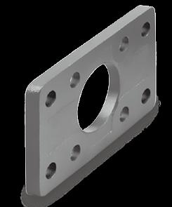
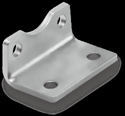
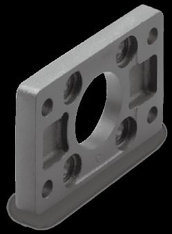

3 ISO ylinder Various mounting bracket options Mounting brackets can be combined according the operating conditions. 85 Rod end (KJ) Floating joint (J) Double clevis (D) P96 Series Single clevis () Double clevis pivot bracket (DS) P96K P96 75R 75K-S/T 75K 75-S/T 75W levis pivot bracket (E) Rod flange (F) Single clevis () xial foot (L) levis pivot bracket with ball joint (ES) Single clevis with ball joint (S) 75 85R 85K-S/T 85K 85-S/T 85W Rod clevis (GKM) Single clevis with ball joint (S) xial foot (L) Series Variations Type Standard P96 Series ction Double acting, Single rod 1 Double acting, Double rod 1 Page 55 ISO Standards 96Y 96K 96 ead flange (G) ISO Non-rotating rod P96K Series Double acting, Single rod 141 Double acting, Double rod *1 125 is the same as the previous model. For details, refer the Web atalog. 128 Related Made u Products Order Switch 129
4 ISO Standard (15552) ir ylinder: Standard Type Double cting, Single/Double Rod P96 Series ø32, ø40, ø50, ø63, ø80, ø100 ow Order The P96 series, standard type, ø125 is the same as the previous model. For details, refer the Web atalog. With au switch With au switch (Built-in magnet) Mounting B Basic L xial foot F Rod flange G ead flange Single clevis D Double clevis * Mounting brackets are shipped gether, but not assembled. P96S B J W P96SD B mm mm mm mm mm mm Nil J JJ K KK J W M9BW ylinder stroke Refer Standard Strokes on page 130. ir cushion on both ends + Bumper cushion Rod boot Without rod boot Nylon tarpaulin (One end) Nylon tarpaulin (Both ends) eat-resistant tarpaulin (One end) eat-resistant tarpaulin (Both ends) Rod Nil W Single rod Double rod S Number of au switches Nil 2 S n n u switch Nil Without au switch * For applicable au switches, refer the table below. Made Order Refer page 130 for details. pplicable u Switches/Refer the Web atalog or Best Pneumatics for further information on au switches. Type Solid state au switch Reed au switch Special function Electrical entry Grommet Diagnostic indication (2-color indicar) Water-resistant (2-color indicar) Grommet Grommet Indicar light Wiring (Output) D Load voltage u switch model Lead wire length [m] Pre-wired connecr pplicable load *1 Water-resistant type au switches can be mounted on the above models, but SM cannot guarantee water resistance. * Lead wire length symbols: 0.5 m Nil (Example) M9NW * Solid state au switches marked with v are produced upon receipt of order. 1 m M (Example) M9NWM 3 m L (Example) M9NWL 5 m Z (Example) M9NWZ * Since there are other applicable au switches than listed above, refer page 146 for details. * The D-9l/M9l/M9lW/M9l au switches are shipped gether, but not assembled. (Only the au switch mounting brackets are assembled before shipment.) * The D-Y59, Y69, Y7P, Y7lW, Z7l, Z80 cannot be mounted on the P96 series. Moreover, the D-M9ll and 9l au switches cannot be mounted on square groove of the P96 series (Nil) (M) (L) (Z) M9N V V V v v I 3-wire (NPN) 5 V, 12 V 3-wire (PNP) M9P V V V v v circuit 2-wire 12 V M9B V V V v v 3-wire (NPN) M9NW V V V v v I 5 V, 12 V Relay, Yes 3-wire (PNP) 24 V M9PW V V V v v circuit PL 2-wire 12 V M9BW V V V v v 3-wire (NPN) M9N*1 v v V v v I 5 V, 12 V 3-wire (PNP) M9P*1 v v V v v circuit 2-wire 12 V M9B*1 v v V v v 3-wire I 5 V 96 V V Yes (NPN equivalent) circuit 100 V 93 V V V V Relay, 2-wire 24 V 12 V I No 100 V or less 90 V V PL circuit
5 ISO Standard (15552) ir ylinder: Standard Type Double cting, Single/Double Rod P96 Series Specifications Symbol -X -XB6 -X4 -X7 -X10 -X11 -X22 -X35 -X65 -X68 -X88 -X89 Made Order (For details, refer pages ) Specifications hange of rod end shape eat-resistant cylinder ( ) With heavy duty scraper Tie-rod, tie-rod nut, etc. made of stainless steel Dual stroke cylinder/double rod type Dual stroke cylinder/single rod type Fluororubber seal With coil scraper Made of stainless steel (ombination of -X7 and -X68) Made of stainless steel (with hard chrome plated pisn rod) Spatter-resistant coil scraper, Lube-retainer, grease for welding (Pisn rod: Stainless steel 304) Spatter-resistant coil scraper, Lube-retainer, grease for welding (Pisn rod: S45) Refer pages 145 and 146 for cylinders with au switches. u Switch Proper Mounting Position (Detection at stroke end) Minimum Stroke for u Switch Mounting Operating Range ow Mount and Move the u Switch ction Double acting Fluid ir Proof pressure 1.5 MPa Max. operating pressure 1.0 MPa Min. operating pressure 0.05 MPa mbient and fluid temperature Lubrication Operating pisn speed llowable stroke lerance Without au switch: (No freezing) With au switch: (No freezing) Not required (Non-lube) mm/s Up 500 stroke: +2 0, stroke: , stroke: , stroke: ir cushion on both ends + Bumper cushion ushion Port size G 1/8 G 1/4 G 1/4 G 3/8 G 3/8 G 1/2 Mounting Standard Strokes Intermediate strokes are available. *1 Please consult with SM for longer strokes. ccessories Standard Option Basic, xial foot, Rod flange, ead flange, Single clevis, Double clevis Standard stroke Mounting Basic Foot Rod ead Single Double flange flange clevis clevis Rod end nut V V V V V V levis pin V Rod end V V V V V V Rod clevis V V V V V V Rod boot V V V V V V * Do not use a rod end (or floating joint) gether with a single clevis with a ball joint (or clevis pivot bracket with a ball joint). * Refer pages for dimensions and part numbers of the accessories. Precautions Max. stroke* , 50, 80, 100, 125, 160, 200, 250, 320, 400, , 50, 80, 100, 125, 160, 200, 250, 320, 400, , 50, 80, 100, 125, 160, 200, 250, 320, 400, 500, , 50, 80, 100, 125, 160, 200, 250, 320, 400, 500, , 50, 80, 100, 125, 160, 200, 250, 320, 400, 500, 600, 700, , 50, 80, 100, 125, 160, 200, 250, 320, 400, 500, 600, 700, Be sure read this before handling the products. Refer page 219 for safety instructions. For actuar and au switch precautions, refer the andling Precautions for SM Products and the Operation Manual on the SM website: W 85-S/T 55 96Y 96K 96 P96K P96 75R 75K-S/T 75K 75-S/T 75W 75 85R 85K-S/T 85K u Switch Made Order Related Products
6 P96 Series Theoretical Output Bore size Rod size Pisn Operating area direction [mm 2 ] OUT Operating pressure [MPa] OUT IN OUT IN OUT IN OUT IN OUT IN OUT IN * Theoretical output [N] = Pressure [MPa] x Pisn area [mm 2 ] IN [N] llowable Kinetic Energy Load mass [kg] ø80 ø100 ø63 ø50 ø40 ø32 Weights Basic weight Basic Foot Flange Single clevis Double clevis dditional weight ll mounting brackets per 50 mm of stroke Rod end ccessories Rod clevis alculation: Example) P96SD OBasic weight 0.66 [kg] (Basic, ø40) Odditional weight 0.18 (kg/50 st) Oylinder stroke 100 [st] OMounting bracket weight 0.32 [kg] (Double clevis) x = 1.32 kg [kg] Maximum speed [mm/s] (Example) Find the upper limit of rod end load when an air cylinder of ø63 is operated at 500 mm/s. From a point indicating 500 mm/s on the axis of abscissas, extend a line upward and find a point where it intersects with a line for the 63 mm bore size. Extend a line from the intersection the left and find a load mass 80 kg. 131
7 ISO Standard (15552) ir ylinder: Standard Type Double cting, Single/Double Rod P96 Series onstruction!2!9!4 q!5 e r i 85-S/T 85W 85 omponent Parts No. Description Material Note 1 Rod cover luminum die-cast 2 ead cover luminum die-cast 3 ylinder tube luminum alloy 4 Pisn rod arbon steel 5 Pisn luminum alloy ø32 ø63 luminum die-cast ø80, ø100 6 ushion ring luminum alloy 7 ushion ring B luminum alloy 8 ushion seal holder luminum alloy 9 Tie-rod arbon steel 10 Tie-rod nut Steel 11 Flat washer Steel ø80, ø Rod end nut Steel 13 ushion valve Resin 14 Bushing Bearing alloy 15 ushion seal Urethane 16 Bumper Urethane 17 Wear ring Resin 18 Pisn seal NBR 19 Rod seal NBR 20 ylinder tube gasket NBR 21 ushion valve seal NBR 22 Magnet o!0 ø80, ø100!1!0 u ø80, ø100 Replacement Parts/Seal Kit (Single rod) Kit no. ontents 32 S S S95-50 Kits include items S S * Seal kits consist of and can be ordered by using the seal kit number corresponding each bore size. * The seal kit includes a grease pack (10 g for ø32 ø50, 20 g for ø63 and ø80, 30 g for ø100). Order with the following part number when only the grease pack is needed. Grease pack part number: GR-S-010 (10 g), GR-S-020 (20 g) Seal Kit (Double rod) Kit no. ontents 32 S95W S95W S95W-50 Kits include items S95W S96W-100 * Seal kits consist of and can be ordered by using the seal kit number corresponding each bore size. * The seal kit includes a grease pack (10 g for ø32 ø50, 20 g for ø63 and ø80, 30 g for ø100). Order with the following part number when only the grease pack is needed. Grease pack part number: GR-S-010 (10 g), GR-S-020 (20 g) Y 96K 96 P96K P96 75R 75K-S/T 75K 75-S/T 75W 75 85R 85K-S/T 85K u Switch Made Order Related Products
8 P96 Series Dimensions Basic: P96S (D) B Stroke (J) ø32, ø40 2 x EE ø80, ø100 PL SL Width across flats SW KK W WB PL 2 x EE port ushion valve PL R E ø80, ø100 With rod boot ød øe R E øb ød øb WB W L12 VD L2 W BG G ZZ + Stroke L8 + Stroke 2 x 4 x RT L9 BG G V 2 x 4 x RT BG l f h h + L8 + V + Stroke Bore size Bore size Stroke range Without rod boot With rod boot ød øe f øb BG ød E EE G KK L2 L8 L9 L12 PL R RT SL SW V VD W WB W ZZ d11 32 Up 2000 Up G 1/ M10 x M6 x Up 2000 Up G 1/ M12 x M6 x Up 2000 Up G 1/ M16 x M8 x Up 2000 Up G 3/ M16 x M8 x Up 2000 Up G 3/ M20 x M10 x Up 2000 Up G 1/ M20 x M10 x l h
9 ISO Standard (15552) ir ylinder: Standard Type Double cting, Single/Double Rod P96 Series Dimensions Basic: P96S (D) B Stroke (J) W E R R E Stroke range øb ød KK ø32, ø40 2 x EE PL Width across flats SW ød øe L12 SL W WB L2 W ushion valve With rod boot at one end PL 2 x EE PL 2 x 4 x RT BG port VD BG G l f h h + L x Stroke 2 x 4 x RT L9 BG G L8 + Stroke ZY + 2 x Stroke WB W VD L2 W + Stroke + Stroke ø80, ø100 ø80, ø100 L12 Width across flats SW KK ød øb øb ød EE PL RT L12 KK SW G BG L8 VD W WB W ZY E R L2 L9 SL d11 32 Up G 1/8 13 M6 x 1 6 M10 x Up G 1/4 14 M6 x M12 x Up G 1/4 14 M8 x M16 x Up G 3/8 16 M8 x M16 x Up G 3/8 16 M10 x M20 x Up G 1/2 18 M10 x M20 x Bore size øe ød f l h Related Products 85 85W 85-S/T 55 96Y 96K 96 P96K P96 75R 75K-S/T 75K 75-S/T 75W 75 85R 85K-S/T 85K u Switch Made Order 134
10 P96 Series Dimensions Basic: P96S (D) B Stroke (JJ) W With rod boot at both ends Width across flats SW PL W WB 2 x EE port ushion valve PL WB W Width across flats SW ød øe ød KK ød øe ød L12 l h VD BG f G 2 x 4 x RT L9 VD BG G f L8 + Stroke 2 x h + L8 + 2 x Stroke l + Stroke h + Stroke L12 KK Stroke range ød EE PL RT L12 KK SW G BG L8 VD W WB E R L9 SL 32 Up G 1/8 13 M6 x 1 6 M10 x Up G 1/4 14 M6 x M12 x Up G 1/4 14 M8 x M16 x Up G 3/8 16 M8 x M16 x Up G 3/8 16 M10 x M20 x Up G 1/2 18 M10 x M20 x Bore size øe ød f l h
11 ISO Standard (15552) ir ylinder: Standard Type Double cting, Single/Double Rod P96 Series Dimensions: With Mounting Bracket (Dimensions are common single rod and double rod.) xial foot (L) TR E1 T 4 x øb O X + Stroke S + Stroke O Bore size E1 TR O T B S X W 85-S/T Rod flange (F) E2 R TF UF ead flange (G) Single clevis () Double clevis (D) 4 x FB XD + Stroke W MF L MF ZF + Stroke D MR EW Single clevis () Bore size R TF FB E2 UF W MF Bore size Bore size EW D 9 MF ZF UB B L MR XD h14 14 EB u Switch 55 96Y 96K 96 P96K P96 75R 75K-S/T 75K 75-S/T 75W 75 85R 85K-S/T 85K B UB EB Double clevis (D) 136 Made Order Related Products

12 P96 Series ccessories Dimensions: Mounting Brackets xial foot (L) TG/2 TG R2 TR E T O øb U Bore size Part no. B TG ±0.2 E TR O U T R2 Screw size 32 L M6 x 16L 40 L M6 x 16L 50 L M8 x 20L 63 L M8 x 20L 80 L M10 x 20L 100 L M10 x 20L * Supplied with 4 mounting screws. Flange (F, G) E R ød TG TF UF FB TG L4 MF Bore size Part no. D 11 øfb TG ±0.2 E R MF TF UF L4 Screw size 32 F M6 x 20L 40 F M6 x 20L 50 F M8 x 20L 63 F M8 x 20L 80 F M10 x 25L 100 F M10 x 25L * Supplied with 4 mounting screws. Single clevis () ød9 l2 Bore size Part no. E1 EW TG1 FL l1 L l2 ød1 ød MR ød2 R * Supplied with 4 mounting screws. l1 137
 l2 l1 Bore size Bore size Part no. TG1 FL l1 L l2 ød1 ød MR ød2 R1 E2 UB B 32 D5032 32.5 22 5 12 5.5 30 10 9.5 6.6 6.")


 ød7 EN 0 0.1 ER øf11 øe L øm N P (Max.) ±0.5 32 S5032 32.5 10.5 22 10 14 15 30 6.6 45 10.5 5.5 5 40 S5040 38 12 25 12 16 18 35 6.6 55 11 5.")

13 ccessories P96 Series Dimensions: Mounting Brackets, Pivot Brackets for ylinder Mounting Double clevis (D) l3 l1 ø levis pivot bracket (E) Single clevis with ball joint (S) l2 l1 Bore size Bore size Part no. TG1 FL l1 L l2 ød1 ød MR ød2 R1 E2 UB B 32 D D D D D D * Supplied with 4 mounting screws, clevis pin, and clevis pin bracket. Part no. ød2 øk øs5 K1 K2 l3 (Max.) (Max.) G1 l1 G2 EM G3 6 (Max.) R1 32 E E E E E E Part no. B (Max.) ød7 EN ER øf11 øe L øm N P (Max.) ± S S S S S S * Supplied with 4 mounting screws. Related Products Made Order 85-S/T 85W Y 96K 96 P96K P96 75R 75K-S/T 75K 75-S/T 75W 75 85R 85K-S/T 85K u Switch 138
 R 32 DS5032 45 14 34 3.3 11.5 32.5 3 5 5.5 22 10 30 10.5 6.6 10 11 17 40 DS5040 55 16 40 4.3 12 38 4 5 5.5 25 10 35 11 6.6 12 13 20 50 DS5050 65 21 45 4.3 14 46.5 4 5 6.")
 Part no. ød3 øn øs5 K1 K2 (Max.")
14 P96 Series Dimensions: Pivot Brackets for ylinder Mounting Double clevis pivot bracket (DS)/for ES accessory l1 l2 L Part no. E B1 B2 B3 L1 TG1 T l1 (Min.) l2 FL (Max.) ød1 ød2 ød3 øn SR (Max.) R 32 DS DS DS DS DS DS * Supplied with 4 mounting screws, clevis pin, and clevis pin bracket. levis pivot bracket with ball joint (ES) Part no. ød3 øn øs5 K1 K2 (Max.) l2 G1 G2 G3 (Max.) EN EU 6 ER (Max.) 32 ES ES ES ES ES ES
![ccessories P96 Series Dimensions: Pisn Rod ccessories Floating joint: J 85-S/T 85W 85 Part no. M B ød E F G P U Load [kn] Weight [g] ngle 32 J30-10-125 M10 x 1.25 49.5 19.5 24](/docs-images/74/69872912/images/15-0.jpg "5 8 8 17 9 0.5 2.5 70 40 J40-12-125 M12 x 1.25 60 20 31 6 11 11 22 13 0.75 4.4 160 ±0.5 50, 63 J50-16-150 M16 x 1.5 71.5 22 41 7.5 14 13.5 27 15 1 11 300 80, 100 J50-20-150 M20 x 1.5 101 28 31 59.")

15 ccessories P96 Series Dimensions: Pisn Rod ccessories Floating joint: J 85-S/T 85W 85 Part no. M B ød E F G P U Load [kn] Weight [g] ngle 32 J M10 x J M12 x ±0.5 50, 63 J M16 x , 100 J M20 x * Black color Rod clevis: GKM (ISO 8140) l1 Part no. e b d l øf h11 (Shaft) øf 9 (ole) l1 c (Min.) a (Max.) 32 GKM10-20 M10 x GKM12-24 M12 x , 63 GKM16-32 M16 x , 100 GKM20-40 M20 x * Supplied with clevis pin and clevis pin bracket. Rod end: KJ (ISO 8139) 55 96Y 96K 96 P96K P96 75R 75K-S/T 75K 75-S/T 75W 75 85R 85K-S/T 85K l3 Part no. d3 ød1 9 h d6 (Max.) b1 h12 l (Min.) 32 KJ10D M10 x KJ12D M12 x , 63 KJ16D M16 x , 100 KJ20D M20 x a l3 140 u Switch Made Order Related Products
16 ISO (15552) Standard ir ylinder: Non-rotating Rod Type Double cting, Single/Double Rod P96K Series ø32, ø40, ø50, ø63, ø80, ø100 With au switch ow Order P96K B W P96KD B W M9BW S With au switch (Built-in magnet) Mounting B Basic L xial foot F Rod flange G ead flange Single clevis D Double clevis * Mounting brackets are shipped gether, but not assembled mm mm mm mm mm mm Rod Nil W ylinder stroke Refer Maximum Strokes on page 142. Single rod Double rod Number of au switches Nil 2 S n n u switch Nil Without au switch * For applicable au switches, refer the table below. ir cushion on both ends + Bumper cushion pplicable u Switches/Refer the Web atalog or Best Pneumatics for further information on au switches. Type Solid state au switch Reed au switch Special function Electrical entry Grommet Diagnostic indication (2-color indicar) Water-resistant (2-color indicar) Grommet Grommet Indicar light Wiring (Output) *1 Water-resistant type au switches can be mounted on the above models, but SM cannot guarantee water resistance. Please contact SM regarding water-resistant types with the above model numbers. * Lead wire length symbols: 0.5 m Nil (Example) M9NW 1 m M (Example) M9NWM 3 m L (Example) M9NWL 5 m Z (Example) M9NWZ Load voltage u switch model * Since there are other applicable au switches than listed above, refer page 146 for details. * The D-9l/M9l/M9lW/M9lL au switches are shipped gether, but not assembled. (Only the au switch mounting brackets are assembled before shipment.) * The D-Y59, Y69, Y7P, Y7lW, Z7l, Z80 cannot be mounted on the P96 series. Moreover, the D-M9ll and 9l au switches cannot be mounted on square groove of the P96 series. 141 D Lead wire length [m] Pre-wired connecr (Nil) (M) (L) (Z) M9N V V V v v I pplicable load 3-wire (NPN) 5 V, 12 V 3-wire (PNP) M9P V V V v v circuit 2-wire 12 V M9B V V V v v 3-wire (NPN) M9NW V V V v v I 5 V, 12 V Relay, Yes 3-wire (PNP) 24 V M9PW V V V v v circuit PL 2-wire 12 V M9BW V V V v v 3-wire (NPN) M9N*1 v v V v v I 5 V, 12 V 3-wire (PNP) M9P*1 v v V v v circuit 2-wire 12 V M9B*1 v v V v v 3-wire I 5 V 96 V V Yes (NPN equivalent) circuit 100 V 93 V V V V Relay, 2-wire 24 V 12 V I No 100 V or less 90 V V PL circuit * Solid state au switches marked with v are produced upon receipt of order.
17 ISO (15552) Standard ir ylinder: Non-rotating Rod Type Double cting, Single/Double Rod P96K Series Specifications Precautions Be sure read this before handling the products. Refer page 219 for safety instructions. For actuar and au switch precautions, refer the andling Precautions for SM Products and the Operation Manual on the SM website: ction Fluid Proof pressure Maximum operating pressure Minimum operating pressure mbient and fluid temperature Maximum Strokes Intermediate strokes are available. *1 Please consult with SM for longer strokes. ccessories Double acting * Do not use a rod end (or floating joint) gether with a single clevis with a ball joint (or clevis pivot bracket with a ball joint). * Refer pages for dimensions and part numbers of the accessories. ir 1.5 MPa 1.0 MPa 0.05 MPa Without au switch: (No freezing) With au switch: (No freezing) Lubrication Not required (Non-lube) Operating pisn speed mm/s llowable stroke lerance Up 500 stroke: , stroke: 0 ushion ir cushion on both ends + Bumper cushion Port size G 1/8 G 1/4 G 1/4 G 3/8 G 3/8 G 1/2 Mounting Basic, xial foot, Rod flange, ead flange, Single clevis, Double clevis Non-rotating accuracy ±0.5 ±0.5 ±0.3 llowable rotational rque [N m] Standard Option Maximum stroke* Mounting Basic Foot Rod flange ead flange Single clevis Double clevis Rod end nut levis pin Rod end Rod clevis Rod boot Refer pages 145 and 146 for cylinders with au switches. u Switch Proper Mounting Position (Detection at stroke end) Minimum Stroke for u Switch Mounting Operating Range ow Mount and Move the u Switch W 85-S/T 55 96Y 96K 96 P96K P96 75R 75K-S/T 75K 75-S/T 75W 75 85R 85K-S/T 85K u Switch Made Order Related Products
18 P96K i q o!7!8!2!6 r e t u w!0!1 ø80, ø100 ø80, omponent Parts No. Description Material Q'ty Note 1 Rod cover luminum die-cast 1 Trivalent chromated 2 ead cover luminum die-cast 1 Trivalent chromated 3 ylinder tube luminum alloy 1 ard anodized 4 Pisn rod Stainless steel 1 5 Pisn luminum alloy 1 6 ushion ring Rolled steel 2 Trivalent zinc chromated 7 Pisn nut Rolled steel 1 Trivalent zinc chromated 8 Non-rotating guide Bearing alloy 1 9 ushion valve Resin 2 10 Tie-rod arbon steel 4 Trivalent zinc chromated 11 Tie-rod nut Rolled steel 8 Trivalent zinc chromated 12 ushion seal holder luminum alloy 2 nodized 13 Wear ring Resin 1 14 Rod seal NBR 1 15 Pisn seal NBR 1 16 ushion seal Urethane 2 17 ushion valve seal NBR 2 18 ylinder tube gasket NBR 2 19 Bumper Urethane 2 20 Rod end nut Rolled steel 1 Trivalent zinc chromated 21 Magnet (1) 22 Flat washer Steel 8 For ø80, ø exagon socket head set screw Steel wire 2 Trivalent black zinc chromated Replacement Parts/Seal Kit (Single rod) Kit no. ontents 32 K K K K K K * Seal kits consist of items!3!6,!8 and can be ordered by using the seal kit number corresponding each bore size. * The seal kit includes a grease pack (10 g for ø32 ø50, 20 g for ø63 and ø80, 30 g for ø100). Order with the following part number when only the grease pack is needed. Grease pack part number: GR-S-010 (10 g), GR-S-020 (20 g) Seal Kit (Double rod) Kits include items!3!6,!8. Kit no. ontents 32 K95W K95W K95W K95W K95W K96W-100 Kits include items!4!6,!8. * Seal kits consist of items!4!6,!8 and can be ordered by using the seal kit number corresponding each bore size. * The seal kit includes a grease pack (10 g for ø32 ø50, 20 g for ø63 and ø80, 30 g for ø100). Order with the following part number when only the grease pack is needed. Grease pack part number: GR-S-010 (10 g), GR-S-020 (20 g) 143
19 ISO (15552) Standard ir ylinder: Non-rotating Rod Type Double cting, Single/Double Rod P96K Series Dimensions (Without mounting bracket) P96K (D) B Stroke ø32, ø40 2 x EE 85 E R D1 Sectional view - R E P96K (D) B E R D1 Sectional view - R E PL øb KK øb KK ø32, ø40 2 x EE PL SL W WB SL VD L9 L2 W WB PL W G Stroke W PL BG 2 x EE port ushion valve ZZ + Stroke 2 x EE port L8 + Stroke ushion valve 2 x 4 x RT PL ø80, ø100 2 x 4 x RT ø80, ø100 2 x 4 x RT VD L9 2 x 4 x RT VD L2 BG BG L2 L12 W G G W + Stroke L8 + Stroke + Stroke ZY + 2 x Stroke * Mounting brackets are the same as standard type. Refer page 136 for details. G PL WB W L9 BG V W WB øb ø80, ø100 BG BG Width across flats SW KK ød øb ø80, ø S/T 85W 55 96Y 96K 96 P96K P96 75R 75K-S/T 75K 75-S/T 75W 75 85R 85K-S/T 85K Stroke range øb D1 ød EE PL RT L12 KK SW G BG L8 VD V W WB W ZZ ZY E R L2 L9 SL d11 32 Up G 1/8 13 M6 x 1 6 M10 x Up G 1/4 14 M6 x M12 x Up G 1/4 14 M8 x M16 x Up G 3/8 16 M8 x M16 x Up G 3/8 16 M10 x M20 x Up G 1/2 18 M10 x M20 x u Switch Made Order Related Products
20 P96 Series u Switch Mounting u Switch Proper Mounting Position (Detection at stroke end) B u Switch Proper Mounting Position u switch model D-M9l(V) D-M9lW(V) D-M9l(V) D-9l(V) B B * djust the au switch after confirming the operating conditions in the actual setting. * The D-M9lV/M9lWV/M9lV/9lV are mountable on ø32 ø63. Minimum Stroke for u Switch Mounting u switch model Number of au switches (Same surface) 50 D-M9l 1, 2 (Different surfaces) 10 D-M9lW n (n 2) 2 (Same surface) 40 D-M9lV 1, 2 (Different surfaces) 10 D-M9lWV n (n 2) 2 (Same surface) D-M9l 1, 2 (Different surfaces) n (n 2) (n 2) 2 (Same surface) 40 D-M9lV 1, 2 (Different surfaces) 10 n (n 2) 2 (Same surface) 50 D-9l 1, 2 (Different surfaces) 10 n (n 2) 2 (Same surface) 40 D-9lV 1, 2 (Different surfaces) 10 n (n 2) * n = 3, 4, 5 * The D-M9lV/M9lWV/M9lV/9lV are mountable on ø32 ø63. Operating Range u switch model D-M9l(V) D-M9lW(V) D-M9l(V) D-9l(V) * Values which include hysteresis are for guideline purposes only, they are not a guarantee (assuming approximately ±30% dispersion) and may change substantially depending on the ambient environment. * The D-M9lV/M9lWV/M9lV/9lV are mountable on ø32 ø
21 u Switch Mounting P96 Series ow Mount and Move the u Switch <pplicable u Switch> Solid state switch D-M9N(V)/M9P(V)/M9B(V) D-M9NW(V)/M9PW(V)/M9BW(V) D-M9N(V)/M9P(V)/M9B(V) Reed switch D-90(V)/93(V)/96(V) ow Mount and Move the u Switch 85 85W 85-S/T u switch mounting screw u switch Use a watchmaker s screwdriver with a handle diameter of 5 6 mm when tightening the au switch mounting screw. u switch mounting screw tightening rque [N m] u switch model Tightening rque D-M9l(V) D-M9lW(V) D-M9l(V) D-9l(V) * s a guide, turn 90 from the position where it comes feel tight. * The D-M9l and 9l cannot be mounted on square groove of the P96 series. * The D-M9lV/M9lWV/M9lV/9lV are mountable on ø32 ø63. Other than the applicable au switches listed in ow Order, the following au switches are mountable. Refer the Web atalog or Best Pneumatics for the detailed specifications. Type Model Electrical entry Features pplicable bore size Solid state Reed D-M9NV, M9PV, M9BV D-M9NWV, M9PWV, M9BWV D-M9NV, M9PV, M9BV Grommet (Perpendicular) Diagnostic indication (2-color indicar) Water-resistant (2-color indicar) D-93V, 96V D-90V Without indicar light * Normally closed (N = b contact) solid state au switches (D-F9G/F9) are also available. For details, refer the Web atalog or Best Pneumatics. * With pre-wired connecr is also available for solid state au switches. For details, refer the Web atalog or Best Pneumatics. ø32 ø63 Related Products Made Order 55 96Y 96K 96 P96K P96 75R 75K-S/T 75K 75-S/T 75W 75 85R 85K-S/T 85K u Switch 146
22 Prior Use u Switch onnections and Examples Sink Input Specifications Source Input Specifications 3-wire, NPN Input 3-wire, PNP Input u switch Black u switch Black OM (PL internal circuit) OM (PL internal circuit) 2-wire Input 2-wire OM u switch u switch OM Input (PL internal circuit) (PL internal circuit) onnect according the applicable PL input specifications, as the connection method will vary depending on the PL input specifications. Examples of ND (Series) and OR (Parallel) onnections * When using solid state au switches, ensure the application is set up so the signals for the first 50 ms are invalid. 3-wire ND connection for NPN output (Using relays) (Performed with au switches only) Relay Load Black u switch 1 u switch 1 Black Load 3-wire OR connection for NPN output Black Load u switch 1 u switch 2 Black u switch 2 Black u switch 2 Black 3-wire ND connection for PNP output (Using relays) Relay Black u switch 1 (Performed with au switches only) Black u switch 1 3-wire OR connection for PNP output Black u switch 1 u switch 2 Black Load u switch 2 Black Load u switch 2 Black Load 2-wire ND connection u switch 1 u switch 2 Load When two au switches are connected in series, a load may malfunction because the load voltage will decline when in the ON state. The indicar lights will light up when both of the au switches are in the ON state. u switches with a load voltage less than 20 V cannot be used. Load voltage at ON = Power supply voltage Residual voltage x 2 pcs. = 24 V 4 V x 2 pcs. = 16 V Example: Power supply is 24 VD Internal voltage drop in au switch is 4 V wire OR connection u switch 1 u switch 2 Load (Solid state) When two au switches are connected in parallel, malfunction may occur because the load voltage will increase when in the OFF state. Load voltage at OFF = Leakage current x 2 pcs. x Load impedance = 1 m x 2 pcs. x 3 kw = 6 V Example: Load impedance is 3 kw. Leakage current from au switch is 1 m. (Reed) Because there is no current leakage, the load voltage will not increase when turned OFF. owever, depending on the number of au switches in the ON state, the indicar lights may sometimes grow dim or not light up, due the dispersion and reduction of the current flowing the au switches.
23 P96 Series Simple Specials/Made Order Please contact SM for detailed specifications, delivery, and prices. Simple Specials Symbol -X0 30 Made Order Symbol -XB6 -X4 -X7 -X10 -X11 -X22 -X35 -X65 -X68 -X88 -X89 hange of rod end shape The following special specifications can be ordered as a simplified Made--Order. Please contact your local sales representative for more details. eat-resistant cylinder ( ) *1 With heavy duty scraper Tie-rod, tie-rod nut, etc. made of stainless steel Dual stroke cylinder/double rod type Dual stroke cylinder/single rod type Fluororubber seal With coil scraper Specifications Specifications Made of stainless steel (ombination of -X7 and -X68) Made of stainless steel (with hard chrome plated pisn rod) Spatter-resistant coil scraper, Lube-retainer, grease for welding (Pisn rod: Stainless steel 304) Spatter-resistant coil scraper, Lube-retainer, grease for welding (Pisn rod: S45) *1 The products with an au switch are not compatible. P96 (Standard type) Double acting Single rod Double rod P96 (Standard type) Double acting Single rod Double rod Related Products Made Order 85-S/T 85W Y 96K 96 P96K P96 75R 75K-S/T 75K 75-S/T 75W 75 85R 85K-S/T 85K u Switch 148
24 P96 Series Simple Specials The following changes are dealt with through the Simple Specials System. For details, refer the Simple Specials in the Web atalog. 1 hange of Rod End Shape pplicable Series Symbol for change Description Model ction of rod end shape P96S Double acting, Single rod X0 30 Standard type P96S-W Double acting, Double rod X0 30 Precautions Symbol -X0 -X30 1. SM will make appropriate arrangements if no dimension, lerance, or finish instructions are given in the diagram. 2. Standard dimensions marked with * will be as follows the rod diameter (D). Enter any special dimension you require. D 6 D 1 mm, 6 < D 25 D 2 mm, D > 25 D 4 mm 3. In the case of the double rod type and single acting retraction type, enter the dimensions when the rod is retracted. 4. Only one side of a double rod can be manufactured is the same shape as the standard type. (The specifications of 0 are that only dimensions and are changed from the standard type.) Symbol: 0 Symbol: 1 Symbol: 2 Symbol: 3 Symbol: ød 30 ørd 30 T W1 L Symbol: 5 Symbol: 6 Symbol: 7 Symbol: 8 Symbol: 9 ørd B MM L MM L MM B L 0.5 file chamfer W 30 W L Symbol: 10 R sphere TP Symbol: 11 R sphere ød 30 Symbol: 12 Symbol: 13 Symbol: R sphere ød ød 30 T W1 L ød MM 30 Symbol: 15 Symbol: 16 Symbol: 17 Symbol: 18 Symbol: 19 ød 30 L ød MM 30 T W1 MM 30 MM 30 MM 30 Symbol: 20 Symbol: 21 Symbol: 22 Symbol: 23 MM 30 MM ød 30 MM ød 30 ørd L 30 Symbol: 24 MM L K ødb Symbol: 25 Symbol: 26 Symbol: 27 MM MM T ødb ød MM MM ød T B W Symbol: 28 ød 30 L Symbol: 29 W L 30 L L K Symbol: 30 L LB K L L MM T L MM 30 W 149 T
25 P96 Series Made Order Please contact SM for detailed dimensions, specifications, and lead times. 1 eat-resistant ylinder ( ) Symbol -XB6 ir cylinder which changed the seal material and grease, so that it could be used even at higher temperature up 150. pplicable Series Description Model ction P96S Double acting, Single rod Standard type P96S-W Double acting, Double rod ow Order Specifications Warning Precautions Standard model no. eat-resistant cylinder mbient temperature range Seal material Grease Specifications other than above and external dimensions Fluororubber eat-resistant grease Same as standard type XB6 Be aware that smoking cigarettes etc. after your hands have come in contact with the grease used in this cylinder can create a gas that is hazardous humans. 2 With eavy Duty Scraper pplicable Series ow Order Standard model no. With heavy duty scraper X4 Specifications: Same as standard type Dimensions: Same as standard type aution Do not replace heavy duty scrapers. Since heavy duty scrapers are press-fit, do not replace the cover only, but rather the entire rod cover assembly. * Operate without lubrication from a pneumatic system lubricar. * Please contact SM for details on the maintenance intervals for this cylinder, which differ from those of the standard cylinder. * In principle, it is impossible make built-in magnet type and the one with au switch. But, as for the one with au switch, and the heat-resistant cylinder with heat-resistant au switch, since it will be differed depending on the series, please contact SM. * Pisn speed is ranged from mm/s. Symbol -X4 It is suitable for using cylinders under the environment, where there are much dusts in a surrounding area by using a heavy duty scraper on the wiper ring, or using cylinders under earth and sand exposed the die-casted equipment, construction machinery, or industrial vehicles. Description Model ction P96S Double acting, Single rod Standard type P96S-W Double acting, Double rod Related Products Made Order 85 85W 85-S/T 55 96Y 96K 96 P96K P96 75R 75K-S/T 75K 75-S/T 75W 75 85R 85K-S/T 85K u Switch 150
26 P96 Series 3 Tie-rod, Tie-rod Nut, etc. Made of Stainless Steel Symbol -X7 When using in locations where the rust generation or corrosion likelihood exists, the standard parts material have been partly changed the stainless steel. pplicable Series Description Model ction P96S Double acting, Single rod Standard type P96S-W Double acting, Double rod ow Order Standard model no. X7 Specifications Parts changed stainless steel Tie-rod, Tie-rod nut, Mounting bracket nut, Spring washer, Lock nut Tie-rod, tie-rod nut, etc. made of stainless steel Specifications other than above Dimensions Same as standard type Same as standard type 4 Dual Stroke ylinder/double Rod Type Symbol -X10 Two cylinders are constructed as one cylinder in a back--back configuration allowing the cylinder stroke be controlled in three steps. pplicable Series Description Model ction Note Standard type P96S Double acting, Single rod Excluding clevis type ow Order P96S Mounting type Stroke + Stroke B X10 Function Dual stroke cylinder B D When air pressure is supplied ports Stroke B B D and, both strokes and B retract. Specifications Maximum manufacturable stroke 1000 When air pressure is supplied ports and, B out strokes. B D Stroke When air pressure is supplied ports and, out strokes. Stroke B B D Stroke When air pressure is supplied ports and, both strokes and B out strokes. Dimensions (Dimensions other than below are the same as standard type.) Stroke Stroke B NB G N L8 + Stroke ( + B) ZZ + Stroke ( + B) L8 ZZ N NB G ø ø ø ø ø ø
27 Made Order P96 Series 5 Dual Stroke ylinder/single Rod Type Symbol -X11 Two cylinders can be integrated by connecting them in line, and the cylinder stroke can be controlled in two stages in both directions. pplicable Series Description Model ction Standard type P96S Double acting, Single rod ow Order P96S Mounting type Stroke + Stroke B- X11 Function Functional description of dual stroke cylinder Stroke B- Stroke B B B B Stroke B Stroke B Precautions Stroke Stroke Stroke B 1) Initial state (0 stroke position) aution 1. Do not supply air until the cylinder is fixed with the attached bolt. 2. If air is supplied without securing the cylinder, the cylinder could lurch, posing the risk of bodily injury or damage the peripheral equipment. Dual stroke cylinder/single rod type 2) 1st stage: Stroke operation When the air pressure is supplied from the port, the rod operates the stroke. 3) 2nd stage: Stroke B- operation Following the 1st stage, when the air pressure is supplied from the port, the rod operates the stroke B-. 4) ylinder retraction When the air pressure is supplied from the B port, the rod retracts completely. Dimensions (Dimensions other than below are the same as standard type.) W Stroke Stroke Stroke B W Stroke B B B B B B Stroke B Stroke B Stroke B Specifications: Same as standard type Stroke or Stroke B operation can be made individually. Double output is possible. Stroke Stroke Stroke Stroke operation 1) Initial state (0 stroke position) 2) Operation When the air pressure is supplied from the port, the rod operates the stroke. Stroke B operation 1) Initial state (0 stroke position) 2) Operation When the air pressure is supplied from the port, the rod operates the stroke B. 1) Initial state (0 stroke position) 2) Double output When the air pressure is supplied the and ports at the same time, the double output can be obtained in the stroke range. 85-S/T 85W Y 96K 96 P96K P96 75R 75K-S/T 75K 75-S/T 75W 75 85R 85K-S/T 85K L8 + Stroke ( + B) ZZ + Stroke ( + B) NB G N L8 ZZ N NB G ø ø ø ø ø ø u Switch Made Order Related Products
28 P96 Series 6 Fluororubber Seal Symbol -X22 pplicable Series Description Model ction P96S Double acting, Single rod Standard type P96S-W Double acting, Double rod ow Order Standard model no. X22 Fluororubber seal (including bumper) Specifications Seal material mbient temperature range Specifications other than above and external dimensions Fluororubber With au switch: (No freezing)*1 Without au switch: (No freezing) Same as standard type *1 Please contact SM, as the type of chemical and the operating temperature may not allow the use of this product. * ylinders with au switches can also be produced; however, au switch related parts (au switch units, mounting brackets, built-in magnets) are the same as standard products. Before using these, please contact SM regarding their suitability for the operating environment. 7 With oil Scraper Symbol -X35 It gets rid of frost, ice, weld spatter, cutting chips adhered the pisn rod, and protects the seals etc. pplicable Series Description Model ction P96S Double acting, Single rod Standard type P96S-W Double acting, Double rod ow Order Standard model no. X35 With coil scraper Specifications: Same as standard type Dimensions: Same as standard type 153
29 Made Order P96 Series 8 Made of Stainless Steel (ombination of -X7 and -X68) Symbol -X65 Suitable for the cases it is likely generate rust by being immersed in the water and corrosion. pplicable Series Description Model ction P96S Double acting, Single rod Standard type P96S-W Double acting, Double rod * There is a maximum stroke limit for P96 cylinder. Maximum Stroke Specifications ow Order 9 Double acting, Single rod ø32: 1800 ø40 ø100: 1700 Parts changed stainless steel Other specifications and external dimensions Made of Stainless Steel (With ard hrome Plated Pisn Rod) Suitable for the cases it is likely generate rust by being immersed in the water and corrosion. pplicable Series Description Model ction P96S Double acting, Single rod Standard type P96S-W Double acting, Double rod Maximum Stroke Double acting, Single rod ø32: 1800 ø40 ø100: 1700 Specifications Parts changed stainless steel Other specifications and external dimensions ow Order Standard model no. Made of stainless steel (ombination of -X7 and -X68) Standard model no. Double acting, Double rod 1000 (Same as standard type) Pisn rod, Rod end nut, Tie-rod, Tie-rod nut, Mounting bracket nut, Spring washer, Lock nut Same as standard type Double acting, Double rod 1000 (Same as standard type) Pisn rod, Rod end nut Same as standard type Made of stainless steel (With hard chrome plated pisn rod) X65 X68 Symbol -X68 Related Products 85 85W 85-S/T 55 96Y 96K 96 P96K P96 75R 75K-S/T 75K 75-S/T 75W 75 85R 85K-S/T 85K u Switch Made Order 154
30 P96 Series 10 Spatter-resistant oil Scraper, Lube-retainer, Grease for Welding (Pisn rod: Stainless steel 304) Symbol -X88 Reduces spatter adhesion and improves durability by the use of the coil scraper, Lube-retainer and grease for welding. pplicable Series Description Model ction P96S Double acting, Single rod Standard type P96S-W Double acting, Double rod ow Order Standard model no. X88 Spatter-resistant coil scraper, Lube-retainer, grease for welding (Pisn rod: Stainless steel 304) Specifications Pisn rod Scraper Grease Other specifications and external dimensions Stainless steel 304 (With hard chrome plated) With coil scraper, With Lube-retainer Grease for welding Same as standard type 11 Spatter-resistant oil Scraper, Lube-retainer, Grease for Welding (Pisn rod: S45) Symbol -X89 Reduces spatter adhesion and improves durability by the use of the coil scraper, Lube-retainer and grease for welding. pplicable Series Description Model ction P96S Double acting, Single rod Standard type P96S-W Double acting, Double rod ow Order Standard model no. X89 Spatter-resistant coil scraper, Lube-retainer, grease for welding (Pisn rod: S45) Specifications Pisn rod Scraper Grease Other specifications and external dimensions S45 (With hard chrome plated) With coil scraper, With Lube-retainer Grease for welding Same as standard type 155
31 P96 Series Specific Product Precautions Be sure read this before handling the products. Refer page 219 for safety instructions. For actuar and au switch precautions, refer the andling Precautions for SM Products and the Operation Manual on the SM website: Warning 1. Do not open the cushion valve more than the allowable number of rotations (following table). lthough the cushion valve is caulked as a retaining mechanism, do not open the cushion valve more than the allowable number of rotations. If air is supplied and operation started without confirming the above condition, the cushion valve may be ejected from the cover. The allowable number of rotations refers the number of rotations until the restricr of the cushion valve is completely opened from the completely closed state. 2. Keep the screwing rque and the unscrewing rque of the cushion valve the allowable rque or below (following table). If a screwing rque or unscrewing rque beyond the allowable rque is applied, the valve will be damaged when the valve is closed completely or exceeds the retaining mechanism when the valve is opened completely, which will dislocate the engagement of the screw and eject the valve. ushion valve width across flats 32, , , exagon wrench JIS 4648 exagon wrench key 2 JIS 4648 exagon wrench key 2 JIS 4648 exagon wrench key 3 llowable number of rotations llowable rque [N m] Be certain activate the air cushion at the stroke end. When the air cushion is inactivated, if the allowable kinetic energy exceeds the value on page 131, the pisn rod assembly or the tie-rod may be damaged. Set the air cushion valid when operating the cylinder. aution djustment 1. When replacing brackets, use the hexagon wrenches shown below. Width across flats Tightening rque [N m] 32, , , Related Products Made Order 85-S/T 85W Y 96K 96 P96K P96 75R 75K-S/T 75K 75-S/T 75W 75 85R 85K-S/T 85K u Switch 156
17% Weight. ISO Cylinder. Cycle time shortened. Lightweight. reduced. Series C96 CAT.ES20-242B
 ISO Cylinder ø32, ø40, ø50, ø63, ø80, ø100 Lightweight New series added Standard type, Double rod: Series C96-W Non-rotating rod type, Single rod: Series C96K Double rod: Series C96K-W Smooth Cylinder:
ISO15552 Cylinders ø32, ø40, ø50, ø63, ø80, ø100, ø125
 ISO2 Cylinders ø, ø, ø, ø, ø, ø0, ø CNOMO and circular grooves are on all four sides. Switch can be slid in. Reduced weight due a change in the configuration of the cover Small sized D-M au switch mountable
10%lighter. 1.7 kg. 1.9 kg. Air Cylinder. New. Weight. Reduced weight by changing the shape of the rod cover and head cover. Series MB1 CAT.
 ir ylinder ø32, ø40, ø50, ø63, ø80, ø100, ø125 New RoS Weight (ø50-100 stroke) 10%lighter Existing model 1.9 kg New Series M1 1.7 kg Reduced weight by changing the shape of the rod cover and head cover.
15 % Weight. ISO Cylinder Ø 32, Ø 40, Ø 50, Ø 63, Ø 80, Ø 100. Cycle time shortened. Lightweight. reduced. Series CP96 CAT.
 ISO ylinder Ø 32, Ø 40, Ø 50, Ø 63, Ø 80, Ø 100 Lightweight ompared with the current P96 series (Ø 40, 100 stroke) New series added Standard type, Double rod: Series P96-W Non-rotating rod type, Single
Compact Cylinder. ISO Standard (21287) C55 Series. ø20, ø25, ø32, ø40, ø50, ø63, ø80, ø100. RoHS C85 C75 C96 C96Y C96K C55
 C55 Series. ø20, ø25, ø32, ø40, ø50, ø63, ø80, ø100. RoHS C85 C75 C96 C96Y C96K C55") 55 96Y 96K 96 P96K P96 75R 75K-S/T 75K 75-S/T 75W 75 85R 85K-S/T 85K 85-S/T 85W 85 ø20, ø25, ø32, ø40, ø50, ø63, ø80, ø100 Related ade to uto Products Order Switch ompact ylinder 55 Series ISO Standard
55 96Y 96K 96 P96K P96 75R 75K-S/T 75K 75-S/T 75W 75 85R 85K-S/T 85K 85-S/T 85W 85 ø20, ø25, ø32, ø40, ø50, ø63, ø80, ø100 Related ade to uto Products Order Switch ompact ylinder 55 Series ISO Standard
Compact Guide Cylinder Series MGQ
 Compact Guide Cylinder Series ø, ø, ø, ø, ø, ø, ø, ø, ø, ø0 ir cylinder with guide integrated that has achieved anti-lateral load and high non-rotating accuracy. Space-saving cylinder. Suitable as stoppers
Compact Slide. Series MXH ø6, ø10, ø16, ø20
 Compact Slide Series ø, ø, ø, ø The use of an endless track linear guide produces a table cylinder having excellent rigidity, linearity and non-rotating accuracy. Endless track linear guide Series Variations
% lighter. Air Cylinder. New. New RoHS. 1.31kg. Series CA2. Reduced weight by changing the shape of the rod cover and head cover.
 ir ylinder Ø 40, Ø 50, Ø 63, Ø 80, Ø 100 Reduced weight by changing the shape of the rod cover and head cover. Weight reduced by up to New RoS 15 (Ø 50-50 stroke) % lighter 1.31kg New 1.54 kg Existing
Free Mount Cylinder. Series CU. A space-saving air cylinder with multiple surfaces capable of mounting directly. Offered in rich variations.
 Free Mount Cylinder Series CU A space-saving air cylinder with multiple surfaces capable of mounting directly. Offered in rich variations. Space-saving The multiple surface direct mounting with a square
Rod end male thread. With rubber bumper 056(9/16") 075(3/4") 106(1 1/16") 150(1 1/2") 250(2 1/2") 300(3")
 075(3/4) 106(1 1/16) 150(1 1/2) 250(2 1/2) 300(3)") T.ID0-1 New ompact ylinder Series NQ8 ore size: 06(9/16 ),(/ ),106(1 1/16 ),(1 1/ ) 00( ),0( 1/ ),00( ),00( ) Now available in 00 ( ) and 00 ( ) bore sizes Standard type ctuation Style uilt-in magnet Rod
T.ID0-1 New ompact ylinder Series NQ8 ore size: 06(9/16 ),(/ ),106(1 1/16 ),(1 1/ ) 00( ),0( 1/ ),00( ),00( ) Now available in 00 ( ) and 00 ( ) bore sizes Standard type ctuation Style uilt-in magnet Rod
Air Cylinder. New RoHS. Series CJ2. are. added to the mounting types. Improved amount of mounting freedom Head cover with boss is added.
 ir Cylinder ø1, ø16 Double foot Double-side bossed added to the mounting types. 4 types 7 types Improved amount of mounting freedom Head cover with boss is added. Head flange are Double foot Double-side
22mm Space required between the bottom of the cylinder body and your equipment is reduced.
 Compact Guide Cylinder ø2,,, ø2,,, ø0, ø63,, ø0 With air cushion Water resistant cylinder are now available. New Up to 7% Weight reduced! New Weight reduced by up to 7% with a shorter guide rod and thinner
Air Cylinder. New. New RoHS. 6 types. Series CJ2. are. added to the mounting types. 4 types 7 types
 ir Cylinder Ø 6, Ø 1, Ø New RoS Double foot ead flange Double-side bossed added to the mounting types. 4 types 7 types New or Ø 6, 3 types are 6 types Double foot Double-side bossed ead flange ead cover
15% lighter. Air Cylinder. New. New. 1.31kg. Series CA2 CAT.ES20-222B. Reduced weight by changing the shape of the rod cover and head cover.
 ir ylinder ø40, ø50, ø63, ø80, ø100 Reduced weight by changing the shape of the rod cover and head cover. Weight reduced by up to ew RoS (ø63-50 stroke) 15% lighter 1.31kg ew 1.54 kg Existing model Easy
3 Position Cylinder. RZQ Series. Provides intermediate stop mechanism. ø32, ø40, ø50, ø63. 2-stage stroke enabled with a small increase in length
 Position ylinder Series ø, ø, ø, ø Provides intermediate stop mechanism 2-stage stroke enabled with a small increase in length Overall length of cylinder tube DQ2 Full stroke First-stage stroke dditional
240% 19% reduced. Compact Slide. MXH Series. Improved by up to. With new high rigidity linear guide. 369g. ø6, ø10, ø16, ø g.
 Compact Slide Series ø, ø, ø, ø RoHS Allowable moment MXS Improved by up to MXQ MXQ 2% MXF MXW MXJ MXP MXY With new high rigidity linear guide MTS Allowable moment improvement illustrated below Allowable
Series CP95 ø32, ø40, ø50, ø63, ø80, ø100
 ISO Cylinder Series CP ø, ø, ø, ø, ø, ø0 Dimensions conform to ISO 6431, VDMA 2462, CETOP RP43P. CJ1 CJP CJ2 CM2 C8 C76 CG1 MB MB1 CP C C2 CA1 CS1 1.-1 Series CP Model Selection Execution Standard Type
Compact Guide Cylinder
 Compact Guide Cylinder Series ø2, ø, ø, ø2, ø, ø, ø, ø, ø, ø0 Series standard type and series high precision ball bushing bearing type (except with end lock) products have been remodeled for a lightweight
Compact Guide Cylinder
 Compact Guide Cylinder Series ø, ø, ø, ø, ø, ø, ø, ø, ø, ø ir cylinder with guide integrated that has achieved anti-lateral load and high non-rotating accuracy. Space-saving cylinder. Suitable as stoppers
C85 (ISO 6432) Series: ø8, ø10, ø12, ø16, ø20, ø25 C75 Series: ø32, ø40
 Series: ø8, ø10, ø12, ø16, ø20, ø25 C75 Series: ø32, ø40") ISO Cylinder (ISO 6432) Series: ø8, ø10, ø12, ø16, ø20, ø25 Series: ø32, ø40 RoS Part numbers set for actuators with mounting brackets, rod end brackets and auto switches available. Now it is not necessary
ISO Cylinder (ISO 6432) Series: ø8, ø10, ø12, ø16, ø20, ø25 Series: ø32, ø40 RoS Part numbers set for actuators with mounting brackets, rod end brackets and auto switches available. Now it is not necessary
1.7 kg. % lighter. 1.9 kg. Air Cylinder. Weight MB1. Reduced weight by changing the shape of the rod cover and head cover.
 Air Cylinder 1 Series ø32, ø40, ø50, ø63, ø80, ø100, ø125 RoHS 10 (ø50-100 stroke) % lighter Current model 1.9 kg 1 Series 1.7 kg J 1 Reduced weight by changing the shape of the rod cover and head cover.
Profile Design Air Cylinder
 Profile Design Air Cylinder Series CP5 ø, ø, ø, ø, ø, ø Features Conforms to VDMA 24 562 (parts 1 and 2), ISO 6431 and CETOP standards. Combines lightweight profile barrel design with enclosed tie rods
Precision Cylinder. MTS Series. ø8, ø12, ø16, ø20, ø25, ø32, ø40 MXH MXS MXQ MXQ MXF MXW MXJ MXP MXY MTS D- -X. Series Variations MTS8
 Precision Cylinder Series, ø, ø6, ø, ø, ø, ø MXS Series Variations Model 8 Standard stroke (mm) 7 7 Rod end configuration Cushion Rubber bumper End lock Made to Order Rod Variable stroke/ through-hole
Compact Guide Cylinder Series MGP
 Compact Guide Cylinder Series MGP ø2, ø, ø, ø, ø, ø, ø, ø,, ø0 MGJ MGP MGQ MGG MGC MGF MGZ MGT Series Variations Series Bearing type Cushion 2 0 Page Standard type MGP With air cushion MGP With end lock
Reduced by Max. 58% Maximum allowable stroke when using clevis bracket CS2 CS Stroke (mm)
") ir ylinder 7. kg eight Reduced by Max. 58% ew arge ore Sizes ø15, ø, ø ighter installation achieved by reducing weight. Die cast rod cover and head cover used to achieve greater weight reduction. Rod bore
ir ylinder 7. kg eight Reduced by Max. 58% ew arge ore Sizes ø15, ø, ø ighter installation achieved by reducing weight. Die cast rod cover and head cover used to achieve greater weight reduction. Rod bore
Series C95 ø32, ø40, ø50, ø63, ø80, ø100
 ISO Cylinder Series C ø, ø, ø, ø, ø, ø0 Dimensions conform to ISO 1, VDMA 2, CETOP RP3P. CJ1 CJP CJ2 CM2 C CG1 M C CA1 CS1 Variations Series Action Style asic Standard variations uit-in magnet Stainless
Free Mount Cylinder. Series. Series CU CAT.EUS20-95 B -UK. Space-saving. Auto Switch Capable P. 4, 23, 37 P. 45 P. 43
 CAT.EUS- B -UK Free Mount Cylinder A space-saving air cylinder with multiple surfaces capable of direct mounting. Offered in many variations. Space-saving The multiple surface direct mounted rectangular
Guide Table. ø40, ø63, ø100
 Guide Table Series MGF ø, ø, ø Low-profile compact cylinder utilizes a large concentric guiding sleeve to provide excellent eccentric load resistance. Mounting height greatly reduced Low-profile cylinder
10% lighter kg kg. Air Cylinder. MB Series. ø32, ø40, ø50, ø63, ø80, ø100, ø125
 ir Cylinder M Series ø3, ø40, ø50, ø63, ø80, ø00, ø5 RoHS 0% lighter CJ (ø40-00 stroke) Weight M Series 0.9 kg CJP CJ JCM CM Current model CM3 CG.0 kg CG3 JM Reduced weight by changing the shape of the
Mini Free Mount Cylinder
 Mini Free Mount Cylinder Series ø, ø, ø, ø, ø, ø1, ø Series 1 ction Stroke 1 2 0 0 0 Clean uto switch series None Rod end Male threaded Without thread Solid state switch D-F D-M9 D-M9 W Female threaded
10 % lighter kg. Air Cylinder kg. New. New. Series. Added ø 125 to standard type.
 ir Cylinder New ø 3, ø 40, ø 50, ø 63, ø 80, ø 100, ø 15 10 % lighter RoS (ø 40-100 stroke) Weight Existing model New 1.01 kg Series dded ø 15 to standard type. 0.91 kg Reduced weight by changing the shape
22 mm Space required between the bottom of the cylinder body and your equipment is reduced. 24% Up to. Compact Guide Cylinder.
 Compact Guide Cylinder Series ø2,,, ø2,,, ø, ø63,, ø0 Up to Weight reduced by up to 24% with a shorter guide rod and thinner plate 24% Weight reduced! 3 types of bearing can be selected. Slide bearing
3 Position Cylinder. ø32, ø40, ø50, ø63 RZQ CDQ2. Bore size (mm)
") Position ylinder Series ø, ø, ø, ø Provides intermediate stop mechanism 2-stage stroke enabled with a small increase in length Overall length of cylinder tube First-stage stroke Full stroke dditional cylinder
Position ylinder Series ø, ø, ø, ø Provides intermediate stop mechanism 2-stage stroke enabled with a small increase in length Overall length of cylinder tube First-stage stroke Full stroke dditional cylinder
Dual rod cylinder with guide function suitable for pick & place applications. Adjustable stroke range: 0 to 5 mm. Axial foot piping.
 Dual Rod Cylinder / Series ø,,,,, Dual rod cylinder with guide function suitable for pick & place applications. Ball bushing bearings and slide bearings are standard for all series. Dimensions for ball
Compact Hydraulic Cylinder
 ompact Hydraulic ylinder Series HQ HQ Series HQ HK HN HM HS H2 H Nominal pressure:. MPa ore size :,,,,,, . MPa ompact Hydraulic ylinder Double cting/single Rod Series H Q ø, ø, ø, ø, ø, ø, ø With uto Switch
Guide Table. MGF Series
 Guide Table MGF Series ø, ø, ø0 Low-profile compact cylinder utilizes a large concentric guiding sleeve to provide excellent eccentric load resistance. Mounting height greatly reduced Low-profile cylinder
Compact Rotary Actuator
 Compact Rotary ctuator Series Rack & Pinion Style/:,,,, : 17 mm : mm : 29 mm : 33 mm : 37 mm CR2 CRU2 CR1 MSU CRJ Rotation 360 type MSQ 360 MSZ MSQ MRQ Series Variations Page Rotating angle 80 to 0 170
How to Order. Nil M. Action S T. Load voltage Wiring. M9NV 5 V, 12 V 3-wire (PNP) M9PV 12 V. F9NWV 5 V, 12 V 3-wire (PNP) F9PWV
 M9PV 12 V. F9NWV 5 V, 12 V 3-wire (PNP) F9PWV") ompact ylinder: Standard Type Single cting, Single Rod, Spring Return/Extend Series QS ø, ø, ø, ø How to Order QS S QS S FWV S uilt-in magnet Mounting style Through-hole/oth ends tapped common (Standard)
ompact ylinder: Standard Type Single cting, Single Rod, Spring Return/Extend Series QS ø, ø, ø, ø How to Order QS S QS S FWV S uilt-in magnet Mounting style Through-hole/oth ends tapped common (Standard)
16% lighter kg. Air Cylinder kg. New. New. Weight. Reduced weight by changing the shape of the rod cover and head cover.
 ir Cylinder ø3, ø40, ø50, ø63, ø80, ø00 New RoS Weight (ø63-00 stroke) 6% lighter New Series Existing model.69 kg.0 kg Reduced weight by changing the shape of the rod cover and head cover. Series/ set
Compact Cylinder. Series CQS CUJ CU CQS CQ2 RQ CQM MU
 Compact Cylinder Series ø, ø, ø, ø Ideal for machine designs with small space requirements The D-M auto switch will not protrude from switch mounting groove. Square body shape gives you flexibility for
Compact Rotary Actuator
 Compact Rotary ctuator CRQ2 Series Rack & Pinion Type/:,,,, : 17 mm : mm : 29 mm : 33 mm : 37 mm CR 2 CR1 MSU CRJ CR1 CRQ2 MSQ MSZ Rotation 360 type 360 CRQ2 MSQ MRQ Series Variations Page Rotating angle
CAT.ES C. Compact Guide Cylinder. SeriesMGP. ø12, ø16, ø20, ø25, ø32, ø40, ø50, ø63, ø80, ø100. New end lock type introduced to Series MGP
 CT.S-7 C Compact Guide Cylinder Series ø, ø, ø, ø2, ø, ø, ø, ø, ø, ø0 New end lock type introduced to Series . Top mount Compact Guide Cylinder Series ø, ø, ø, ø2, ø, ø, ø, ø, ø, ø0 Four mounting types
ISO Standard Hydraulic Cylinder
 ISO Standard ydraulic ylinder Series S/SG Series S Q N Nominal pressure: S Pa ore size :,,,, Related quipment Series SG Nominal pressure: - Pa ore size : 3,,,,, 51 ISO Standard ydraulic ylinder Series
Dual rod cylinder with guide function suitable for pick & place applications. Adjustable stroke range: 0 to 5 mm. Axial foot piping.
 Dual Rod Cylinder J/ Series ø, ø, ø, ø, ø, Dual rod cylinder with guide function suitable for pick & place applications. Ball bushing bearings and slide bearings are standard for all series. Dimensions
Compact Rotary Actuator
 Compact Rotary ctuator Series Rack & Pinion Style/:,,,, : 17 mm : mm : 29 mm : 33 mm : 37 mm 360 type 360 CR2 CRU2 CR1 MSU CRJ CR1 MSQ MSZ MSQ MRQ Series Variations Standard Made to Order Rotating angle
Compact Cylinder/Plate type
 Compact Cylinder/Plate type Series :,,, Width: Reduced by up to % (compared with SMC series) Total length: Reduced by up to % Volume: Reduced by up to 1% Weight: Reduced by up to % (compared with SMC series
15% lighter. Air Cylinder. New. 1.31kg. Series CA2 CAT.ES20-222A. Reduced weight by changing the shape of the rod cover and head cover.
 ir ylinder ø, ø, ø, ø, ø Reduced weight by changing the shape of the rod cover and head cover. Weight reduced by up to ew RoS (ø- stroke) % lighter 1.31kg ew 1.54 kg Existing model Easy air cushion control
16% lighter Existing model
 ir Cylinder ø3, ø40, ø50, ø63, ø80, ø00 New RoS Weight (ø63-00 stroke) 6% lighter Existing model New Series.0 kg.69 kg Reduced weight by changing the shape of the rod cover and head cover. Series/ set
Guide Table. Series MGF
 Guide Table Series MGF ø, ø, ø0 Low-profile compact cylinder utilizes a large concentric guiding sleeve to provide excellent eccentric load resistance. Mounting height greatly reduced Low-profile cylinder
Series CP95. Profile Design ISO/VDMA Air Cylinder. Increased kinetic energy absorption. Improved end of stroke cushion capacity
 Profile Design ISO/VDMA Air Cylinder Series CP95 Improved end of stroke cushion capacity Piston rod lurching has been eliminated at the end of stroke positions by means of a floating seal mechanism. Increased
Air Cylinder. New RoHS. Series CG1. Female rod end available as standard. Rod end styles suitable for the application can be selected.
 ir Cylinder ø 20, ø 25, ø 32, ø 40, ø 50, ø 63, ø 80, ø 100 New RoS Female rod end available as standard Selectable Rod end styles suitable for the application can be selected. Female thread Male thread
How to Order D 30 D M9BW. Made to Order Specifications Bore size Number of. Rod end configuration Cylinder stroke (mm) Nil
 Nil") With auto switch RSG RSDG With auto switch (uilt-in magnet) uilt-in Magnet Cylinder Model If a built-in magnet cylinder without an auto switch is required, there is no need to enter the symbol for the
With auto switch RSG RSDG With auto switch (uilt-in magnet) uilt-in Magnet Cylinder Model If a built-in magnet cylinder without an auto switch is required, there is no need to enter the symbol for the
Heavy Duty Stopper Cylinder
 Heavy Duty Stopper Cylinder Series ø, ø32 To stop pallets gently Stopper cylinder with built-in shock absorber Amount of energy absorption can be adjusted to suit the load. Stops the workpiece gently with
Free Mount Cylinder for Vacuum
 Free Mount Cylinder for Vacuum Series A free mount cylinder with a vacuum passage in the rod to meet the requirements for Air cylinder + Vacuum pad. A vacuum passage has been provided in the rod of the
Mechanically Jointed Rodless Cylinders
 Mechanically Jointed Rodless Cylinders MY Series Basic short type (Rubber bumper) MY Series Bore sizes ø, ø, ø0 added MYB MY Basic standard type (ir cushion) MYB MYB Series MYM MYC MY MY T Bore sizes ø,
Air Cylinder. ø125, ø140, ø160, ø180, ø200, ø250, ø300. Lube. Single rod. Non-lube. Series. Air-hydro. Lube. Double rod. Non-lube CS1W.
 Air ylinder Series S,,,,,, Series Variations Series Action asic Standard variations Page J JP J Standard Series S Series S Double acting Single rod Series S Double rod Series SW 4 4 M G M M A S S Series
Wide Type Parallel Style Air Gripper
 Wide Type Parallel Style ir Gripper ø, ø6, ø2, ø25 Weight Max. % reduction 585 g 525 g ø6, Opening/Closing stroke: 3 mm RoHS Weight reduced by the change of the body shape and internal construction M Dust
Lube. Single rod. Non-lube CS1. series. Air-hydro. Lube. Double rod CS1W series. Non-lube. Non-lube
 Air ylinder S Series,,,,,, J Series Variations Series Action asic Standard variations Page JP J JM Standard S Series S Series Double acting Single rod S series Double rod SW series 5 548 M M3 G G3 JM M
Cylinder with Lock. MNB Series. A locking cylinder ideal for intermediate stops, emergency stops and drop prevention. ø32, ø40, ø50, ø63, ø80, ø100
 ylinder with Lock M Series ø, ø, ø, ø, ø, ø locking cylinder ideal for intermediate stops, emergency stops and drop prevention. Simple construction force magnifying mechanism is employed based on the wedge
Parallel Style Air Gripper
 INFRMATIN Parallel tyle Air Gripper With Dust Cover Model variations with excellent dust proof and drip proof dust cover are expanded. MHZL2 Long stroke type MHZL2 series ø1, ø16 and ø2 with dust cover
How to Order M9BW. Action. Double acting Single acting. Load voltage Electrical entry direction M9NWV M9NW 12 V 5 V, M9BWV M9BW 12 V 12 V
 Angular Type Air Gripper/Standard Type 2 Series ø, ø1, ø20, ø25 How to Order Angular type air gripper 2 20 Bore size mm 1 1 mm 20 20 mm 25 25 mm D S Action D Double acting Single acting M9BW Made to Order
Compact Hydraulic Cylinder. ø20, ø25, ø32, ø40, ø50, ø63, ø80, ø100. How to Order Z73. Bore size. 20mm 25mm 32mm 40mm 50mm 63mm 80mm 100mm
 ompact ydraulic ylinder MPa Series KG ø, ø, ø, ø, ø, ø, ø, ø0 With uto Switch With auto switch (built-in magnet) KG DKG Mounting: asic type 0 ore size ow to Order mm mm mm mm mm mm mm 0mm Z3 Refer to "uto
Miniature Guide Rod Cylinder ±0.1. Mounting from 2 directions
 Miniature Guide Rod Cylinder Series Non-rotating accuracy : Height ±0.1 Mounting from 2 directions idth Overall length Two auto switches can be mounted even for mm strokes Integral wiring/piping to one
Air Slide Table. Traveling parallelism: mm. Mounting from the through-holes on the top. Tapped for mounting a work piece
 ir Slide Table Series Height: mm/width: mm/length: mm () Front mounting accuracy: 0.01 mm Top mounting accuracy: 0.0 mm Traveling parallelism: 0.00 mm Note 1) Note ) Integrated front mounting part and
Compact Guide Cylinder with Lock
 Compact Guide Cylinder with Lock Series,,,, ø,,, ø0 CLG CL CN2 MLC Drop prevention when the pressure of air source is decreased or the residual pressure is released. Drop prevention for press fitting jig
1.134 L INEAR A CTUATOR: AIR C YLINDER S ERIES C95
 1.134 L INEAR A CTUATOR: AIR C YLINDER H O W M ADE I N USA T ECHNICAL T O O R D E R C95 AIR C YLINDERS C95 P ISTON R OD S Basic K Non-Rotating P ISTON - Basic D Magnetic B ORE IN MM 50 63 80 100 B S T
Cylinder with Lock CNA. ø40, ø50, ø63, ø80, ø100 Suitable for intermediate stops, emergency stops and drop prevention
 ylinder with Lock Series ø, ø, ø, ø, ø Suitable for intermediate stops, emergency stops and drop prevention Simple construction force magnifying mechanism is employed based on the wedge effect of the taper
Series C96. ISO Cylinder. Conforming to ISO ø32, ø40, ø50, ø63, ø80, ø100, ø125. Variations. Standard. Standard variations Built-in magnet
 ISO Cylinder Series C ø, ø, ø, ø, ø, ø0, ø Conforming to ISO 12 Variations Series ction Type Basic Standard variations Built-in magnet Stainless steel rod Option Heat resistant Bore Standard Series C Double
How to Order. Manual release type. Lock position. H Head end lock. With rod boot. Nil J K M9NWV M9NW H7C M9PWV M9PW M9BWV M9BW M9NAV M9NA M9PAV M9PA
 Courtesy of CM/Flodyne/Hydradyne Motion Control Hydraulic Pneumatic Electrical Mechanical (0) - www.cmafh.com CDG1 With auto switch (uilt-in magnet) Mounting style asic style L xial foot style F Rod side
Mini Rotary Actuator/Rack & Pinion Style
 Mini Rotary Actuator/Rack & Pinion Style Series CRJ :, CRB2 CRBU2 CRB MSU CRJ CRA CRA CRQ2 MSQ MSZ CRQ2X MSQX MRQ PAT. PEND D- 79 Mini Rotary Actuator Series CRJ Rack & Pinion Style/:, Compact 9.5 23.5
15% lighter. Air Cylinder. 1.31kg. CA2 Series. Reduced weight by changing the shape of the rod cover and head cover. Weight reduced by up to
 Air ylinder A Series ø40, ø50, ø63, ø80, ø100 RoHS Reduced weight by changing the shape of the rod cover and head cover. Weight reduced by up to (ø50-50 stroke) 15% lighter 1.31kg Easy air cushion control
Traveling parallelism: mm. Mounting from the through-holes on the top. Tapped for mounting a work piece
 ir Slide Table Series RoHS Height: mm/width: mm/length: mm () Traveling parallelism: 0.00 mm Note 1) Front mounting accuracy: 0.01 mm Note ) Top mounting accuracy: 0.0 mm Integrated front mounting part
Pin Cylinders. Series CJP2/CJP. 2 auto switches can even be mounted on a cylinder with ø4 bore size (5 mm stroke). One-touch fitting can be connected.
. One-touch fitting can be connected.") Pin ylinders eries JP/JP auto switches can even be mounted on a cylinder with ø ( mm stroke). uto switch One-touch fitting can be connected. (Panel mount type) ø One-touch fitting, miniature fitting, and
Pin ylinders eries JP/JP auto switches can even be mounted on a cylinder with ø ( mm stroke). uto switch One-touch fitting can be connected. (Panel mount type) ø One-touch fitting, miniature fitting, and
Series M Solid state to -56/Z76-59/Y59-5P/Y7P -J59/Y59-59/Y7N Surge absorber (+) Reverse flow prevent diode ( ) (+) ( ) (+) ( ) (+) (+) ( )
 Reverse flow prevent diode ( ) (+) ( ) (+) ( ) (+) (+) ( )") asic iring Solid state 3 wire NPN (hen power source for and load is not common.) Sink input specifications 3-wire NPN Switch 3-wire N connection for NPN output (using relays) Series M uto Switch onnections
asic iring Solid state 3 wire NPN (hen power source for and load is not common.) Sink input specifications 3-wire NPN Switch 3-wire N connection for NPN output (using relays) Series M uto Switch onnections
2 way basic mounting: Through-hole or both ends tapped
 Compact Cylinder Series ø, ø, ø, ø Ideal for machine designs with small space requirements The D-M auto switch will not protrude from switch mounting groove. Square body shape gives you flexibility for
Angular Style Air Gripper
 Angular Style Air Gripper Series /A/M 15 Angular style air gripper Series /A/M - Auto switch is attachable. 8 mm x 0 mm x mm g Body option (Only for A-) Side piping Port Port A- Short body. 1 mm x 0 mm
Mechanically Jointed Rodless Cylinder High Precision Guide Type. How to Order 16 G 300 L M9N. Stroke. Refer to Standard Stroke table.
 Mechanically Jointed Rodless ylinder igh Precision uide Type eries MY/T ø, ø, ø T MY uide type igh precision guide with single axis igh precision guide with double axis ymbol Nil TN TF Type M thread Rc
180 Angular Style Air Gripper
 8 Angular Style Air Gripper Series 2/2 Cam Style / Rack & Pinion Style 99 8 Angular Style Air Gripper Cam Style Rack & Pinion Style Series 2/2 Series 2/Cam Style Light and compact size in small bore sizes
Parallel Style Air Gripper: Wide Type
 Parallel Style Air Gripper: Wide Type Series MHL Built-in dust-protection mechanism A scraper with a dust lip is adopted for all rod rotating parts. A large amount of gripping force is provided through
Air Cylinder. ø125, ø140, ø160, ø180, ø200, ø250, ø300. Lube. Single rod. Non-lube. Series. Air-hydro. Lube. Double rod. Non-lube CS1W.
 Air ylinder Series S,,,,,, Series Variations Series Action asic Standard variations Page J JP J Standard Series S Series S Double acting Single rod Series S Double rod Series SW 4 M G M M A S S Series
Mini Rotary Actuator/Rack & Pinion Style
 Mini Rotary Actuator/Rack & Pinion Style Series CRJ :, CRB2 CRBU2 CRB MSU CRJ CRA CRQ2 MSQ MSZ CRQ2X MSQX MRQ PAT. PEND D- 79 Mini Rotary Actuator Series CRJ Rack & Pinion Style/:, Compact 9.5 23.5 43(54)
Standard Type Dual-Rod Cylinder. ø6, ø10, ø15, ø20, ø25, ø32. How to Order
 Standard Type ual-rod ylinder Series ø, ø, ø, ø, ø2, ø32 ompact Type J M L M earing type Slide bearing all bushing bearing How to Order 0 Y7W S Number of auto switches Nil 2 pcs. S pc. n "n" pcs. ore size/standard
Hygienic Design Cylinder
 ygienic Design ylinder Series Y water resistant cylinder configured for easy cleaning Series Y ISO standard type Series Y asic type Series YQ With guide Series YG J G Y Series 0 0 External seal material
15% Weight reduced. ISO Cylinder ø32, ø40, ø50, ø63, ø80, ø100. Cycle time shortened. Lightweight. Series CP96 CAT.EUS20-241A-UK
 ISO Cylinder ø32, ø40, ø50, ø63, ø80, ø100 ISO Standard (15552) Lightweight Up to 15% Weight reduced Compared with the existing CP96 series (ø40, 100 stroke) By adopting a new cushion method (Air cushion
Air Cylinder. New RoHS. Series CM2. Female rod end available as standard. Rod end styles suitable for the application can be selected.
 ir Cylinder ø 20, ø 25, ø 32, ø 40 New RoS Female rod end available as standard Selectable Rod end styles suitable for the application can be selected. Female thread Male thread Easy fine adjustment of
Series MGP. Compact Guide Cylinder. New end lock type introduced to Series MGP. ø12, ø16, ø20, ø25, ø32, ø40, ø50, ø63, ø80, ø100
 Compact Guide Cylinder Series ø, ø, ø, ø2, ø, ø, ø, ø, ø, ø0 New end lock type introduced to Series.22- CL MLG CN CNG MNB CNS CLS CB CV/MVG CXW CXS CXT MX MXU MXH MXS MXQ MXF MXW MXP MG MGQ MGG MGC MGF
69% 30.5 mm 16 mm. Compact Guide Cylinder. Compact. lighter 0.32 kga0.1 kg (Compared with the current MGP-Z series, ø16, 10 mm stroke) Weight
 Weight") Compact Guide Cylinder ø12, ø16, ø20, ø25, ø32, ø40, ø50, ø63, ø80, ø100 RoHS Compact Overall length shortened New s ø80, ø100 added. Port thread types NPT, G added. Height shortened JMGP ø32 25 mm stroke
Compact Guide Cylinder ø12, ø16, ø20, ø25, ø32, ø40, ø50, ø63, ø80, ø100 RoHS Compact Overall length shortened New s ø80, ø100 added. Port thread types NPT, G added. Height shortened JMGP ø32 25 mm stroke
2 way basic mounting: Through-hole or both ends tapped
 Compact Cylinder Series CQS ø, ø, ø, ø Ideal for machine designs with small space requirements The D-M auto switch will not protrude from switch mounting groove. Square body shape gives you flexibility
ISO Cylinders. Series CP96/C96 CAT.EUS20-204A-UK. Series CP96. Series C96. ø32, ø40, ø50, ø63, ø80, ø100, ø125
 ISO Cylinders ø, ø, ø, ø, ø, ø0, ø Conforming to ISO 2. CNOMO and circular grooves are set on all four sides. Switch can slide in. Profile Design ISO Cylinder Series CP6 Variations Series C6 Series Action
Series MK ø12, ø16, ø20, ø25, ø32, ø40, ø50, ø63
 otary lamp ylinder/standard Series MK ø, ø, ø, ø, ø, ø, ø5, ø ow to Order MK 1 3 S otary clamp cylinder Mounting Symbol Style ore size Through hole & both ends tapped (Standard) ø, ø oth ends tapped Through
Series CQS. Compact Cylinder. Square body shape gives you flexibility for machine design
 ompact ylinder Series QS ø, ø, ø, ø Ideal for machine designs with small space requirements The - and -M auto switches will not protrude from switch mounting groove. Square body shape gives you flexibility
Air Slide Table. Traveling parallelism: mm. Mounting from the through-holes on the top. Tapped for mounting a work piece
 ir Slide Table Series Height: mm/width: mm/length: mm () Front mounting accuracy: 0.01 mm Top mounting accuracy: 0.0 mm Traveling parallelism: 0.00 mm Note 1) Note ) Integrated front mounting part and
Double Power Cylinder. Non-rotating Double Power Cylinder. Series MGZ. Series MGZR (without MGJ MGP MGQ MGG MGC MGF MGZ MGT. non-rotating mechanism)
") Non-rotating Double Power Cylinder Series Double Power Cylinder Series R (without non-rotating mechanism) 2 Non-rotating Double Power Cylinder Double extension output power!! Our unique construction doubles
Non-rotating Double Power Cylinder Series Double Power Cylinder Series R (without non-rotating mechanism) 2 Non-rotating Double Power Cylinder Double extension output power!! Our unique construction doubles
Small Bore Hydraulic Cylinder
 Small ore ydraulic Cylinder CN Series CQ CK CN CM CS C C D- CN Series Nominal pressure: MPa ore size :,,, Stainless Steel Tube Small ore ydraulic Cylinder for MPa CN Series ø, ø, ø, ø Equipped with cushion
Mechanically Jointed Hy-rodless Cylinder with Brake
 Mechanically Jointed y-rodless Cylinder with Brake Series ø, ø, ø Brake mechanism has been compactly integrated into the slide table which enables intermediate stops of the rodless cylinder. Large holding
Basic type / Direct mount type
 Basic type / Direct mount type Series / ø, ø, ø, ø, ø, ø, ø, ø, ø3 CYS CYL CY CYF Courtesy of Steven Engineering, Inc.- Ryan Way, South San Francisco, CA 0-30-Main Office: () -0-Outside Local Area: (00)
Compact Rotary Actuator
 Compact Rotary Actuator Series Rack & Pinion Style/:,,,, : 17 mm : mm : 29 mm : 33 mm : 37 mm CRB2 CRBU2 CRB1 MSU CRJ CRA1 Rotation 360 type 360 MSZ MRQ Series Variations Page Rotating angle 80 to 0 170
Valve Mounted Cylinder. Action Built-in magnet. With air cushion. Double acting. Standard. Nonrotating rod. Standard. rod. Standard. rod.
 eries V/MVGQ,,,, 2,,,, 63,, eries Variations eries eries V ction uilt-in magnet With air cushion variations uilt-in One-touch fitting With auto switch With strong scraper Page RE RE X ouble acting -1-
Round Type Hydraulic Cylinder
 Round Type ydraulic Cylinder CM Series CQ CK C CM CS C C D- CM Series ominal pressure: 3. MPa ore size :,,, 3 3. MPa Round Type ydraulic Cylinder CM Series ø, ø, ø, ø pplicable uto Switches/Refer to pages
Non-rotating Double Power Cylinder. Double Power Cylinder MGZ. (without non-rotating MGJ MGP -Z MGP MGPW MGQ MGG MGC MGF MGT D- -X
 Non-rotating Double Power Cylinder Double Power Cylinder (without non-rotating Series Series R mechanism) MGJ -Z W MGQ MGG MGC MGF MGT 23 D- -X Non-rotating Double Power Cylinder Double extension output