TECHNICAL CATALOGUE H / IEC / ATEX / EN / REV.1 / 2017 HELICAL GEAREDMOTORS STANDARD IEC DIRECTIVE ATEX
|
|
|
- Damon Brown
- 5 years ago
- Views:
Transcription


1 H / IEC / ATEX / EN / REV.1 / 2017 HELICAL GEAREDMOTORS STANDARD IEC DIRECTIVE ATEX
2 H Seres / ATEX / IEC INDEX 1. GENERAL INFORMATION 1.1 ATEX SYMBOLS AND FORMULAS Symbols Formulas PRODUCT SELECTION SERVICE FACTOR INSTALLATION 9 2. PRODUCT INFORMATION 2.1 DESIGN FEATURES TYPOLOGY Desgnaton Versons Modularty MOUNTING POSITIONS Mountng postons Poston of termnal box CRITICAL APPLICATIONS Crtcal applcatons Informaton MOTOR FLANGE AVAILABILITY HA Motor flange avalablty H Motor flange avalablty OUTPUT SHAFT BEARINGS OVERHUNG LOAD Informaton Input Output LUBRICATION Informaton Lubrcants Specal lubrcants 28 1
3 H Seres / ATEX / IEC INDEX Quantty MOMENTS OF INERTIA DIMENSIONS 3.1 REDUCERS/GEARED MOTORS HA HA CHA IHA HA CHA IHA HA CHA IHA H CH IH H..2/ CH..2/ IH..2/ ELECTRIC MOTORS Electrc motors Standard hgh effcency (TS), hgh (TH) and premum- (TP) motors Nomnal power WEIGHT END SHAFT ACCESSORIES AND OPTIONS 4.1 OUTPUT FLANGE BACKSTOP DEVICE THERMAL PROTECTOR REINFORCED OIL SEALS FOR OUTPUT SHAFT 69 2
4 H Seres / ATEX / IEC INDEX 5. ATEX AVAILABILITY 5.1 ATEX AVAILABILITY PERFORMANCES 6.1 H/HA GEARED MOTORS (50Hz) IH/IHA GEAR REDUCER rpm IH/IHA GEAR REDUCER rpm IH/IHA GEAR REDUCER rpm IH/IHA GEAR REDUCER rpm IH/IHA GEAR REDUCER rpm IH/IHA GEAR REDUCER rpm SALES CONDITIONS 7.1 SALES CONDITIONS 234 3
5 H Seres / ATEX / IEC 1.1 ATEX ATEX Certfcaton The gear reducers descrbed n ths catalogue, defned as ATEX, were desgned and manufactured n complance wth: Drectve ATEX 2014/34/UE. If used by followng the nstructons set forth n the INSTALLATION AND USE INSTRUCTIONS Atex Manual (provded as an attachment to the suppled products), ATEX MOTOVARIO gear reducers can be used n one of the followng envronments: Group II Category 2G and 2D Zone 1/21 for gases and dusts (gas group IIB) wth the followng protecton methods: Protecton aganst gnton: EN (c) constructonal safety EN (k) lqud mmerson Group II Category 3G and 3D Zone 2/22 for gases and dusts Protecton aganst gnton: EN (c) constructonal safety The room temperature envsaged for the applcaton must range between -20 and + 40 C (*). The products certfed for use n Zone 1/21 can be used also n Zone 2/22. To dentfy the envronment nsde whch the Atex certfcaton of the specal gear reducer s lmted, refer to Atex Performance Tables. The classfed unts are manufactured and marked to comply wth the provsons of Drectve ATEX 2014/34/UE. UNINTENDED USE It s strctly forbdden to use the gear reducer: nsde an area wth equpment category I (mnes lkely to become endangered by fredamp); nsde an Area classfed as more severe than specfed on product label; at a room temperature not fallng wthn the specfed lmts (*); under condtons (P1, n1, M2) that, even ndvdually, exceed the values specfed nsde Atex Performance Tables. 4
6 H Seres / ATEX / IEC 1.2 SYMBOLS AND FORMULAS Symbols Physcal dmenson Symbol Symbol unts of measure Input Output Power P P 1 P 2 Requested power Pr Pr 1 Pr 2 Nomnal power Pn Pn 2 Torque M M 1 M 2 Nomnal torque Mn Requested torque Mr Mr 1 Mr 2 Speed n n 1 n 2 Force F Radal load Fr Fr 1 Fr 2 Axal load Fa Fa 1 Fa 2 Reducton rato Dynamc effcency η d Servce factor f.s. Statc Dynamc Calculated s d c Maxmum max Mnmum mn Moment of nerta J [kgm 2 ] J 1 Ambent temperature T amb [ C] Dmenson [mm] 5
7 H Seres / ATEX / IEC 1.2 SYMBOLS AND FORMULAS Formulas REDUCER Startng or stoppng tme t= v / a [s] Velocty n rotary moton Speed velocty Angular velocty v= π * d * n / 60 v= ω * r n= 60 * v / (π * d) ω= v / r [m/s] [rad/s] Acceleraton or deceleraton accordng to a startng / stoppng tme a= v / t [m/s 2 ] Angular acceleraton Startng or stoppng dstance (accordng to acceleraton / deceleraton or angular velocty) Horzontal translaton force Vertcal translaton force (lftng) Inclned plane translaton force α= n / (9,55 * t) α= ω / t s= a * t 2 / 2 s= v * t /2 F= µ * m * g F= m * g F= m * g (µ * cosβ + senβ) [rad/s 2 ] [m] m= mass [kg]; g= gravty acceleraton [m/s 2 ]; µ= frcton coeffcent; β= angle of nclnaton Moment of nerta J= m * v 2 / ω 2 [kgm 2 ] Torque M= F * d / 2 M= J * ω / t MOTOR and GEARMOTOR Startng tme ta= (Jext+Jm)*n n /9,55+(M peak -Mr) [s] Brakng tme ts= (Jext+Jm)*n n /9,55+(M peak +Mr) [s] Motor rotaton angle durng startng φ= n n * ta / 19,1 [rad] Motor rotaton angle durng brakng φ= n n * ts / 19,1 [rad] Power avalable at the shaft of sngle phase motor P= V * I * ɲ *cosω [W] Power avalable at the shaft of three phase motor P= 1,73 * V * I * ɲ * cosω [W] RUNNING at 60Hz Speed velocty at 60Hz n 60Hz = 1,2 * n 50Hz Power at 60Hz P1 60Hz = P1 50Hz * V 60Hz /V 50Hz If nput voltage at 60 Hz (V 60Hz ) corresponds to wndng voltage at 50 Hz (V 50Hz ), power doesn t change P1 60Hz = P1 50Hz If nput voltage at 60 Hz (V 60Hz ) s 20% hgher than wndng voltage at 50 Hz (V 50Hz ), power ncreases by 20% P1 60Hz = 1,2 P1 50Hz Torque at 60Hz M 60hz = M 50Hz * P1 60Hz / (1,2 * P1 50Hz ) Servce factor at 60Hz f.s. 60Hz = f.s. 50Hz * 1,175 * P1 50Hz / P1 60Hz - 6
8 H Seres / ATEX / IEC 1.3 PRODUCT SELECTION For correctly selectng a gear reducer or geared motor, several essental peces of data are requred: 1. The rotatonal nput speed to the gear reducer (n 1 ) and the rotatonal output speed (n 2 ). Through these two values t s possble to calculate the reducton rato () of the gear reducer usng the followng formula: =n 1 /n 2 2. The torque requred by the applcaton (Mr 2 ). The geared motor or gear reducer can be selected once ths data s known. Ths gude helps you to select the rght product n just a few steps: Geared motor selecton 1. Determne the applcaton s actual servce factor (s.f.). Ths parameter depends on the type of load of the powered machne, the number of starts per hour and the hours of operaton (refer to the Servce factor paragraph). 2. Calculate the nput power Pr 1 usng the requred torque value Mr 2, the speed n 2 and dynamc effcency value. Pr1= (Mr 2 *n 2 )/(9550*η d ). The dynamc effcency value depends on the type of gear reducer and on the number of gear reducton stages. (To calculate the effcency value see ts page). 3. Consult the geared motor performance tables and dentfy a normalsed power value exceedng the requred power Pr 1, such that: Pr 1 4. Once the sutable nomnal power has been dentfed, select the geared motor capable of generatng the rotatonal speed closest to the desred n 2 value and wth servce factor s.f. greater or equal to that requred by the applcaton. For Atex product selecton, use the servce factor f.s. Atex. In the geared motor selecton tables the combnatons nclude 2-pole, 4-pole and 6-pole motors powered at 50Hz. Gear reducer selecton 1. Determne the applcaton s servce factor (s.f.) (consult to the Servce factor paragraph on ts page). 2. Calculate the reducton rato from the requested output speed n 2 and from the nput speed n1. =n 1 /n 2 3. Calculate the torque Mc 2 for selectng the gear reducer through the torque requred by the applcaton Mr 2 and the servce factor s.f.: Mc 2 =Mr 2 *(f.s.) 4. Consult the Gear Reducer Performance tables lookng for the reducer that, wth the reducton rato closer to the calculated one, has a nomnal torque so that: Mc 2 For Atex product Selecton, refer to Atex Gear Reducer Performance tables. Checks Once the gear reducer or geared motor has been selected, the followng checks should be performed: A. Thermal power The gear reducer s thermal power must be equal to or greater than the nstalled mechancal power, or the power requred by the applcaton accordng to the ndcatons contaned n the secton (refer to the Thermal power paragraph). B. Maxmum torque Generally, the maxmum torque (peak nstantaneous load) that can be appled to the gear reducer must not exceed 200% of the nomnal torque (ATEX - M 2 max). C. Radal loads 1. Verfy that the radal loads actng on the nput and/or output shafts are wthn wth the values ndcated n the catalogue. If they exceed these values, ncrease the sze of the gear reducer or modfy the external load capacty. Durng the checkng phase, t s mportant to remember that the values ndcated n the catalogue refer to loads actng on the md-pont of the shaft protruson, therefore, f the load s appled to a dfferent poston, approprate formulas must be used to calculate the admssble load n the desred poston (refer to the Radal loads paragraph). 2. If accessory output shafts are present, make sure that the appled load s compatble wth shaft sze. If help s needed: contact MOTOVARIO TECHNICAL SERVICE. D. If an electrc motor s gong to be ftted to the selected gear reducer, check for ts applcablty by referrng to the confguraton table (see paragraph Motor flange avalablty ). From IEC 180 motors, verfy f necessary to support the motor wth feet. In case of need please contact MOTOVARIO TECHNICAL SERVICE. 7

9 H Seres / ATEX / IEC 1.4 SERVICE FACTOR The servce factor (f.s.) depends on the operatng condtons the gear reducer s subjected to. The parameters that need to be taken nto consderaton to select the most adequate servce factor correctly comprse: LOAD: type of load of the operated machne : A - B - C length of daly operatng tme: hours/day ( ) start-up frequency: starts/hour (*) A - unform = fa 0,3 B - moderate shocks = fa 3 C - heavy shocks = fa 10 fa = Je/Jm Je [kgm 2 ] moment of reduced external nerta at the drve-shaft Jm [kgm 2 ] moment of nerta of motor If fa > 10 call our Techncal Servce. A. Screw feeders for lght materals, fans, assembly lnes, conveyor belts for lght materals, small mxers, lfts, cleanng machnes, fllers, control machnes. B. Wndng devces, woodworkng machne feeders, goods lfts, balancers, threadng machnes, medum mxers, conveyor belts for heavy materals, wnches, sldng doors, fertlzer scrapers, packng machnes, concrete mxers, crane mechansms, mllng cutters, foldng machnes, gear pumps. C. Mxers for heavy materals, shears, presses, centrfuges, rotatng supports, wnches and lfts for heavy materals, grndng lathes, stone mlls, bucket elevators, drllng machnes, hammer mlls, cam presses, foldng machnes, turntables, tumblng barrels, vbrators, shredders. 8


10 H Seres / ATEX / IEC 1.5 INSTALLATION To nstall the gear reducer t s necessary to note the followng recommendatons: Check the correct drecton of rotaton of the gear reducer output shaft before fttng the unt to the machne. In the case of partcularly lengthy perods of storage (4/6 months), f the ol seal s not mmersed n the lubrcant nsde the unt, t s recommended to change t snce the rubber could stck to the shaft or may even have lost the elastcty t needs to functon properly. Whenever possble, protect the gear reducer aganst solar radaton and bad weather. Ensure the motor cools correctly by ensurng good passage of ar from the fan sde. In the case of ambent temperatures < -5 C or > +40 C call the Techncal Servce. The varous parts (pulleys, gear wheels, couplngs, shafts, etc.) must be mounted on the shafts usng specal threaded holes or other systems that anyhow ensure correct operaton wthout rskng damage to the bearngs or external parts of the unts. Lubrcate the surfaces n contact to avod sezure or oxdaton. Pantng must defntely not go over rubber parts and the holes on the breather plugs, f any. For unts equpped wth ol plugs, replace the closed plug used for shppng wth the specal breather plug. Check the correct level of the lubrcant through the ndcator, f there s one. Startng must take place gradually, wthout mmedately applyng the maxmum load. When there are parts, objects or materals under the motor drve that can be damaged by even lmted spllage of ol, specal protecton should be ftted. Assemblng motor on pam flange When the unt s suppled wthout motor, t s necessary to follow these recommendaton to ensure the correct assembly of the electrc motor. Check that the tolerances for the motor shaft and flange correspond to the standard. Carefully clean the shaft, spgot and surfaces of the flange removng traces of pant and drt, and confrm the key s ftted correctly. Ft the half couplng/sleeve to the motor shaft (see pcture) takng care to ensure the motor shaft and bearngs are not damaged by avodng excessve force and where necessary usng assembly equpment. Place the couplngs elastc element onto the motor half couplng and poston the motor up to the gear unt ensurng the couplng element s algned wth the drven half couplng. Complete the assembly usng the fxng bolts. Key-ways wth tghtened tolerances. In case of Atex unts, ft gasket (to be requested to Motovaro) between PAM flange and motor. Flexble jont PAM Sleeve 9
11 H Seres / ATEX / IEC 2.1 DESIGN FEATURES Motovaro products are suppled wth the followng surface treatment features: De-cast alumnum alloy cases for gears De-cast materals undergo the followng surface cleanng operatons: De-burrng by means of a mechancally operated shearng system. Accurate shot-peenng. Pantng. Washng and passvaton. Grey-coloured cast-ron cases for gears De-cast materals are always panted. Pantng specfcatons: Orange-peel blue epoxy-polyester RAL Polyester resn based heat-hardenng powders, altered wth epoxy resns. Mechancal propertes Tests carred out onto degreased Unchm whte lattens (flm thckness: 60 mcrons) comply wth the followng specfcatons: adherence (ISO2409). Heat resstance 24 HOURS AT 150 C. Corroson strength ASTM B 117/97 salt fog from 100 to 500 hours dependng on the support s prelmnary treatment. Performance: Loadng capacty n accordance wth DIN 3990, ISO 6336, AGMA 2101, ISO 10300, DIN 3991, ISO 281, DIN 743. Dynamc η: The effcency s the rato between the output power P2 and the power absorbed by thegear reducer P 1 : η=p 2 /P 1. H/HA-range helcal gear reducers have an average value equal to: H..1 stages = 0,97 H..2 stages = 0,96 H..3 stages = 0,94 10
12 H Seres / ATEX / IEC 2.2 TYPOLOGY Desgnaton 11


13 H Seres / ATEX / IEC 2.2 TYPOLOGY Versons 12

14 H Seres / ATEX / IEC 2.2 TYPOLOGY 13
15 H Seres / ATEX / IEC 2.2 TYPOLOGY Modularty 14

16 H Seres / ATEX / IEC 2.2 TYPOLOGY 15

17 H Seres / ATEX / IEC 2.3 MOUNTING POSITIONS Mountng postons The mountng poston of the gear unt dentfes ts space orentaton. B3 mountng poston, as from a techncal pont of vew, ensures lower ol splash, better lubrcaton and less heatng. HA1T - H1T HA1F - H1F H1M 16


18 H Seres / ATEX / IEC 2.3 MOUNTING POSITIONS HA2/3T - H2/3T HA2/3F - H2/3F Poston of termnal box Unless otherwse specfed when orderng, the gear reducer s suppled wth termnal box n poston 1. 17
19 H Seres / ATEX / IEC 2.4 CRITICAL APPLICATIONS Crtcal applcatons H A31 A30 A40 A50 A60 V5 - V1: 1500 < n1 < 3000 n1 > 3000 B B B B B V3 - V6 B B B B B H V5 - V1: 1500 < n1 < 3000 B B n1 > 3000 B B B B B B A A V3 - V6 B B B B B B B B Verfed applcaton A Applcaton not recommended B Check the applcaton and/or call our techncal servce Informaton The performance gven n the catalogue correspond to mountng poston B3 or smlar, when the frst stage s not entrely mmersed n ol. For other mountng postons and/or partcular nput speeds, refer to the tables that hghlght dfferent crtcal stuatons for each sze of gear reducer. It s also necessary to take due consderaton of and carefully assess the followng applcatons by callng our Techncal Servce: To avod the use as multpler. Use n servces that could be hazardous for people f the gear reducer fals. Applcatons wth especally hgh nerta. Use as a lftng wnch. Applcatons wth hgh dynamc stran on the case of the gear reducer. In places wth T amb under -5 C or over 40 C. Use n chemcally aggressve envronments. Use n a salty envronment. Mountng postons not envsaged n the catalogue. Use n radoactve envronments. Use n envronments pressures other than atmospherc pressure. Avod applcatons where even partal mmerson of the reducer s requred. In the presence of overloadng due to full load, brakng, shocks or other statc and dynamc causes, please verfy that the peak torque s less than 2*. 18
20 H Seres / ATEX / IEC 2.5 MOTOR FLANGE AVAILABILITY HA Motor flange avalablty B10 = Compact electrc motor versons. These tables report all possble dmensons. Please verfy servce factor. NOTE Atex gear reducers szes HA32-HA43-HA42-HA43-HA52-HA53-HA62-HA63: avalable for 3G/3D certfcaton, only CH A32 5,38 30,55 B10 B10 B10 CH A32 35,44 60,67 B10 B10 CH A33 51,32 166,61 B10 B10 CH A33 193,3 347,29 B10 B10 B10 CH A41 1,45 5,45 B10 B10 B10 CH A41 7,88 10,83 B10 B10 CH A42 5,38 30,55 B10 B10 B10 B10 CH A42 35,44 60,67 B10 B10 CH A43 51,32 166,61 B10 B10 B10 B10 CH A43 193,3 347,29 B10 B10 CH A51 1,45 5,45 B10 B10 B10 B10 CH A51 7,88 10,83 B10 B10 CH A52 5,14 25,43 B10 B10 B10 B10 CH A52 29,89 61,87 B10 B10 CH A53 49,8 163,05 B10 B10 B10 B10 CH A53 200,27 353,98 B10 B10 CH A61 1,33 4,38 B10 B10 B10 B10 CH A61 7,75 10,67 B10 B10 CH A62 5,14 25,43 B10 B10 B10 B10 CH A62 29,89 61,87 B10 B10 CH A63 49,8 163,05 B10 B10 B10 B10 CH A63 200,27 353,98 B10 B H A31 2,55 4,75 B5 B5 B5 H A31 5,1 7,88 B5 B5 H A31 10,83 B5 H A32 5,38 30,55 B5 B5-B14 B5-B14 H A32 35,44 60,67 B5 B5-B14 H A33 51,32 166,61 B5 B5-B14 H A33 193,3 347,29 B5 B5-B14 B5-B14 H A41 1,45 5,45 B5 B5-B14 B5-B14 H A41 7,88 10,83 B5 B5-B14 H A42 5,38 30,55 B5 B5-B14 B5-B14 B5-B14 H A42 35,44 60,67 B5 B5-B14 H A43 51,32 166,61 B5 B5-B14 B5-B14 B5-B14 H A43 193,3 347,29 B5 B5-B14 H A51 1,45 5,45 B5 B5-B14 B5-B14 B5-B14 H A51 7,88 10,83 B5 B5-B14 H A52 5,14 25,43 B5-B14 B5-B14 B5-B14 B5-B14 H A52 29,89 61,87 B5-B14 B5-B14 H A53 49,8 163,05 B5 B5-B14 B5-B14 B5-B14 H A53 200,27 353,98 B5 B5-B14 H A61 1,33 4,38 B5-B14 B5-B14 B5-B14 B5-B14 H A61 7,75 10,67 B5-B14 B5-B14 H A62 5,14 25,43 B5-B14 B5-B14 B5-B14 B5-B14 H A62 29,89 61,87 B5-B14 B5-B14 H A63 49,8 163,05 B5 B5-B14 B5-B14 B5-B14 H A63 200,27 353,98 B5 B5-B14 19
21 H Seres / ATEX / IEC 2.5 MOTOR FLANGE AVAILABILITY H Motor flange avalablty B11 = Compact electrc motor versons. These tables report all possble dmensons. Please verfy servce factor. *Confguraton suppled wth thermal protector. **For motor sze 063 the PH verson does not exst. NOTE Atex geared motors (versons wth compact electrc motor B11): avalable for 3G/3D certfcaton, only. CH - H - PH ,70 B5-B11 B5-B11 B5-B11 B5-B11 B5-B11 6,23 B5-B11 B5-B11 B5-B11 B5-B11 B5-B11 7,76 B5-B11 B5-B11 B5-B11 B5-B11 B5-B11 8,87 B5-B11 B5-B11 B5-B11 B5-B11 B5-B11 10,14 B5-B11 B5-B11 B5-B11 B5-B11 B5-B11 11,76 B5-B11 B5-B11 B5-B11 B5-B11 B5-B11 13,72 B5-B11 B5-B11 B5-B11 B5-B11 B5-B11 14,66 B5-B11 B5-B11 B5-B11 B5-B11 B5-B11 16,77 B5-B11 B5-B11 B5-B11 B5-B11 B5-B11 18,20 B5-B11 B5-B11 B5-B11 B5-B11 B5-B11 19,90 B5-B11 B5-B11 B5-B11 22,68 B5-B11 B5-B11 B5-B11 B5-B11 B5-B11 23,83 B5-B11 B5-B11 B5-B11 26,39 B5-B11 B5-B11 B5-B11 29,70 B5-B11 B5-B11 B5-B11 32,89 B5-B11 B5-B11 B5-B11 37,92 B5-B11 B5-B11 B5-B11 41,40 B5-B11 B5-B11 B5-B11 47,25 B5-B11 B5-B11 B5-B11 CH - H - PH 033 ** ,59 B5-B11 B5-B11 B5-B11 B5-B11 66,78 B5-B11 B5-B11 B5-B11 B5-B11 74,84 B5-B11 B5-B11 B5-B11 B5-B11 99,27 B5-B11 B5-B11 B5-B11 B5-B11 108,05 B5-B11 B5-B11 123,71 B5-B11 B5-B11 B5-B11 B5-B11 143,33 B5-B11 B5-B11 178,61 B5-B11 B5-B11 197,17 B5-B11 B5-B11 245,70 B5-B11 B5-B11 CH - H - PH ,44 B5-B11 B5-B11 B5-B11 2,00 B5-B11 B5-B11 B5-B11 2,55 B5-B11 B5-B11 B5-B11 2,71 B5-B11 B5-B11 B5-B11 3,11 B5-B11 B5-B11 B5-B11 3,59 B5-B11 B5-B11 B5-B11 4,20 B5-B11 B5-B11 B5-B11 5,00 B5-B11 B5-B11 B5-B11 5,50 B5-B11 B5-B11 B5-B11 6,09 B5-B11 B5-B11 B5-B11 7,67 B5-B11 B5-B11 B5-B11 8,75 B5-B11 B5-B11 B5-B11 CH - H - PH ,46 B5-B11 B5-B11 B5-B11 B5-B11 B5-B11 7,19 B5-B11 B5-B11 B5-B11 B5-B11 B5-B11 8,91 B5-B11 B5-B11 B5-B11 B5-B11 B5-B11 10,31 B5-B11 B5-B11 B5-B11 B5-B11 B5-B11 11,80 B5-B11 B5-B11 B5-B11 B5-B11 B5-B11 13,57 B5-B11 B5-B11 B5-B11 B5-B11 B5-B11 15,96 B5-B11 B5-B11 B5-B11 B5-B11 B5-B11 19,00 B5-B11 B5-B11 B5-B11 B5-B11 B5-B11 21,00 B5-B11 B5-B11 B5-B11 B5-B11 B5-B11 23,15 B5-B11 B5-B11 B5-B11 26,04 B5-B11 B5-B11 B5-B11 B5-B11 B5-B11 27,50 B5-B11 B5-B11 B5-B11 30,45 B5-B11 B5-B11 B5-B11 34,10 B5-B11 B5-B11 B5-B11 37,76 B5-B11 B5-B11 B5-B11 43,75 B5-B11 B5-B11 B5-B11 47,53 B5-B11 B5-B11 B5-B11 54,25 B5-B11 B5-B11 B5-B11 CH - H - PH 043 * ,83 B5-B11 B5-B11 B5-B11 B5-B11 76,67 B5-B11 B5-B11 B5-B11 B5-B11 87,05 B5-B11 B5-B11 B5-B11 B5-B11 114,55 B5-B11 B5-B11 B5-B11 B5-B11 125,69 B5-B11 B5-B11 142,04 B5-B11 B5-B11 B5-B11 B5-B11 165,38 B5-B11 B5-B11 205,07 B5-B11 B5-B11 227,50 B5-B11 B5-B11 282,10 B5-B11 B5-B11 20
22 H Seres / ATEX / IEC 2.5 MOTOR FLANGE AVAILABILITY CH - H - PH ,27 B5-B11 B5-B11 B5-B11 B5-B11 1,42 B5-B11 B5-B11 B5-B11 B5-B11 2,13 B5-B11 B5-B11 B5-B11 B5-B11 2,57 B5-B11 B5-B11 B5-B11 B5-B11 B5-B11 3,17 B5-B11 B5-B11 B5-B11 B5-B11 B5-B11 3,69 B5-B11 B5-B11 B5-B11 B5-B11 B5-B11 4,00 B5-B11 B5-B11 B5-B11 B5-B11 B5-B11 4,77 B5-B11 B5-B11 B5-B11 B5-B11 B5-B11 5,25 B5-B11 B5-B11 B5-B11 B5-B11 B5-B11 5,82 B5-B11 B5-B11 B5-B11 B5-B11 B5-B11 7,33 B5-B11 B5-B11 B5-B11 8,38 B5-B11 B5-B11 B5-B11 CH - H - PH ,73 B5-B11 B5-B11 B5-B11 B5-B11 6,89 B5-B11 B5-B11 B5-B11 B5-B11 8,53 B5-B11 B5-B11 B5-B11 B5-B11 9,56 B5-B11 B5-B11 B5-B11 B5-B11 11,51 B5-B11 B5-B11 B5-B11 B5-B11 14,24 B5-B11 B5-B11 B5-B11 B5-B11 16,59 B5-B11 B5-B11 B5-B11 B5-B11 B5-B11 18,00 B5-B11 B5-B11 B5-B11 B5-B11 B5-B11 19,97 B5-B11 B5-B11 B5-B11 B5-B11 B5-B11 21,67 B5-B11 B5-B11 B5-B11 B5-B11 B5-B11 24,71 B5-B11 B5-B11 B5-B11 B5-B11 B5-B11 26,18 B5-B11 B5-B11 B5-B11 B5-B11 B5-B11 28,44 B5-B11 B5-B11 B5-B11 B5-B11 B5-B11 31,52 B5-B11 B5-B11 B5-B11 B5-B11 B5-B11 33,00 B5-B11 B5-B11 B5-B11 38,98 B5-B11 B5-B11 B5-B11 B5-B11 B5-B11 45,36 B5-B11 B5-B11 B5-B11 49,13 B5-B11 B5-B11 B5-B11 56,11 B5-B11 B5-B11 B5-B11 CH - H - PH 053 * ,81 B5-B11 B5-B11 B5-B11 B5-B11 72,75 B5-B11 B5-B11 B5-B11 B5-B11 90,51 B5-B11 B5-B11 B5-B11 B5-B11 108,95 B5-B11 B5-B11 B5-B11 B5-B11 134,76 B5-B11 B5-B11 B5-B11 B5-B11 157,29 B5-B11 B5-B11 194,56 B5-B11 B5-B11 216,38 B5-B11 B5-B11 267,65 B5-B11 B5-B11 CH - H - PH ,34 B5-B11 B5-B11 B5-B11 B5-B11 2,13 B5-B11 B5-B11 B5-B11 B5-B11 2,57 B5-B11 B5-B11 B5-B11 B5-B11 3,17 B5-B11 B5-B11 B5-B11 B5-B11 3,69 B5-B11 B5-B11 B5-B11 B5-B11 4,00 B5-B11 B5-B11 B5-B11 B5-B11 4,77 B5-B11 B5-B11 B5-B11 B5-B11 5,25 B5-B11 B5-B11 B5-B11 B5-B11 5,82 B5-B11 B5-B11 B5-B11 B5-B11 7,33 B5-B11 B5-B11 B5-B11 B5-B11 8,38 B5-B11 B5-B11 B5-B11 B5-B11 CH - H - PH ,38 B5-B11 B5-B11 B5-B11 B5-B11 B5-B11 5,93 B5-B11 B5-B11 B5-B11 B5-B11 B5-B11 7,39 B5-B11 B5-B11 B5-B11 B5-B11 B5-B11 8,50 B5-B11 B5-B11 B5-B11 B5-B11 B5-B11 9,39 B5-B11 B5-B11 B5-B11 B5-B11 B5-B11 11,69 B5-B11 B5-B11 B5-B11 B5-B11 B5-B11 12,67 B5-B11 B5-B11 B5-B11 B5-B11 B5-B11 14,75 B5-B11 B5-B11 B5-B11 B5-B11 B5-B11 16,29 B5-B11 B5-B11 B5-B11 B5-B11 B5-B11 17,67 B5-B11 B5-B11 B5-B11 B5-B11 B5-B11 20,28 B5-B11 B5-B11 B5-B11 B5-B11 B5-B11 23,27 B5-B11 B5-B11 B5-B11 B5-B11 B5-B11 25,70 B5-B11 B5-B11 B5-B11 B5-B11 B5-B11 29,33 B5-B11 B5-B11 B5-B11 B5-B11 32,00 B5-B11 B5-B11 B5-B11 B5-B11 B5-B11 36,99 B5-B11 B5-B11 B5-B11 B5-B11 40,33 B5-B11 B5-B11 B5-B11 B5-B11 46,06 B5-B11 B5-B11 B5-B11 B5-B11 CH - H - PH ,45 B5-B11 B5-B11 B5-B11 B5-B11 54,61 B5-B11 B5-B11 B5-B11 B5-B11 68,00 B5-B11 B5-B11 B5-B11 B5-B11 85,82 B5-B11 B5-B11 B5-B11 B5-B11 B5-B11 94,76 B5-B11 B5-B11 B5-B11 B5-B11 B5-B11 118,00 B5-B11 B5-B11 B5-B11 B5-B11 B5-B11 135,40 B5-B11 B5-B11 B5-B11 B5-B11 B5-B11 149,51 B5-B11 B5-B11 B5-B11 B5-B11 B5-B11 170,67 B5-B11 B5-B11 B5-B11 186,18 B5-B11 B5-B11 B5-B11 B5-B11 B5-B11 215,21 B5-B11 B5-B11 B5-B11 234,67 B5-B11 B5-B11 B5-B11 268,00 B5-B11 B5-B11 B5-B11 21
23 H Seres / ATEX / IEC 2.5 MOTOR FLANGE AVAILABILITY CH - H - PH ,30 B5-B11 1,43 B5-B11 1,93 B5-B11 2,54 B5-B11 B5-B11 B5-B11 3,25 B5-B11 B5-B11 B5-B11 3,72 B5-B11 B5-B11 B5-B11 4,00 B5-B11 B5-B11 B5-B11 4,67 B5-B11 B5-B11 B5-B11 5,54 B5-B11 B5-B11 B5-B11 B5-B11 B5-B11 6,08 B5-B11 B5-B11 B5-B11 B5-B11 B5-B11 7,50 B5-B11 B5-B11 B5-B11 B5-B11 B5-B11 8,44 B5-B11 B5-B11 B5-B11 B5-B11 B5-B11 CH - H - PH ,39 B5-B11 B5 5,95 B5-B11 B5 7,39 B5-B11 B5 8,02 B5-B11 B5 8,85 B5-B11 B5 11,01 B5-B11 B5 13,50 B5-B11 B5-B11 B5-B11 B5 14,90 B5-B11 B5-B11 B5-B11 B5 16,60 B5-B11 B5-B11 B5-B11 B5 18,53 B5-B11 B5-B11 B5-B11 B5 19,38 B5-B11 B5-B11 B5-B11 B5 21,39 B5-B11 B5-B11 B5-B11 B5 22,80 B5-B11 B5-B11 B5-B11 B5 26,60 B5-B11 B5-B11 B5-B11 B5 27,88 B5-B11 B5-B11 B5-B11 B5-B11 B5-B11 31,15 B5-B11 B5-B11 B5-B11 B5-B11 B5-B11 34,38 B5-B11 B5-B11 B5-B11 B5-B11 B5-B11 38,70 B5-B11 B5-B11 B5-B11 B5-B11 B5-B11 42,75 B5-B11 B5-B11 B5-B11 B5-B11 B5-B11 48,13 B5-B11 B5-B11 B5-B11 B5-B11 B5-B11 CH - H - PH ,53 B5-B11 B5-B11 B5-B11 B5-B11 B5-B11 71,48 B5-B11 B5-B11 B5-B11 B5-B11 B5-B11 78,87 B5-B11 B5-B11 B5-B11 B5-B11 B5-B11 85,60 B5-B11 B5-B11 B5-B11 B5-B11 B5-B11 98,09 B5-B11 B5-B11 B5-B11 B5-B11 B5-B11 112,78 B5-B11 B5-B11 B5-B11 B5-B11 B5-B11 124,44 B5-B11 B5-B11 B5-B11 B5-B11 B5-B11 142,15 B5-B11 B5-B11 B5-B11 B5-B11 154,76 B5-B11 B5-B11 B5-B11 B5-B11 B5-B11 162,35 B5-B11 B5-B11 179,13 B5-B11 B5-B11 195,07 B5-B11 B5-B11 222,78 B5-B11 B5-B11 CH - H - PH ,29 B5-B11 B5 B5 1,41 B5-B11 B5 B5 2,03 B5-B11 B5 B5 2,48 B5-B11 B5 B5 3,27 B5-B11 B5-B11 B5-B11 B5 B5 3,70 B5-B11 B5-B11 B5-B11 B5 B5 4,22 B5-B11 B5 B5 4,88 B5-B11 B5-B11 B5-B11 B5 B5 5,27 B5-B11 B5-B11 B5-B11 B5 B5 6,23 B5-B11 B5-B11 B5-B11 B5 7,55 B5-B11 B5-B11 B5-B11 B5 8,40 B5-B11 B5-B11 B5-B11 B5 CH - H - PH ,26 B5-B11 B5 B5 6,36 B5-B11 B5 B5 7,05 B5-B11 B5 B5 8,27 B5-B11 B5 B5 9,99 B5-B11 B5 B5 11,09 B5-B11 B5 B5 13,32 B5-B11 B5-B11 B5-B11 B5 B5 16,09 B5-B11 B5-B11 B5-B11 B5 B5 17,85 B5-B11 B5-B11 B5-B11 B5 B5 19,80 B5-B11 B5-B11 B5-B11 B5 B5 21,44 B5-B11 B5-B11 B5-B11 B5 B5 24,00 B5-B11 B5-B11 B5-B11 B5 B5 25,89 B5-B11 B5-B11 B5-B11 B5 B5 28,73 B5-B11 B5-B11 B5-B11 B5 B5 30,70 B5-B11 B5-B11 B5-B11 B5 34,20 B5-B11 B5-B11 B5-B11 B5 38,45 B5-B11 B5-B11 B5-B11 41,30 B5-B11 B5-B11 B5-B11 B5 45,82 B5-B11 B5-B11 B5-B11 B5 51,52 B5-B11 B5-B11 B5-B11 CH - H - PH ,47 B5-B11 B5 69,69 B5-B11 B5-B11 B5-B11 B5 79,80 B5-B11 B5-B11 B5-B11 B5 84,16 B5-B11 B5-B11 B5-B11 B5 93,36 B5-B11 B5-B11 B5-B11 B5 100,07 B5-B11 B5-B11 B5-B11 B5 120,84 B5-B11 B5-B11 B5-B11 B5 134,06 B5-B11 B5-B11 B5-B11 B5 143,40 B5-B11 B5-B11 B5-B11 B5-B11 160,82 B5-B11 B5-B11 B5-B11 B5-B11 181,07 B5-B11 B5-B11 B5-B11 B5-B11 194,21 B5-B11 B5-B11 B5-B11 B5-B11 215,45 B5-B11 B5-B11 B5-B11 B5-B11 242,59 B5-B11 B5-B11 B5-B11 B5-B11 22
24 H Seres / ATEX / IEC 2.5 MOTOR FLANGE AVAILABILITY CH - H - PH ,23 B5 B5 B5 1,42 B5 B5 B5 1,81 B5 B5 B5 2,00 B5-B11 B5 B5 B5 2,48 B5-B11 B5 B5 B5 2,95 B5-B11 B5 B5 B5 3,14 B5-B11 B5 B5 B5 3,58 B5-B11 B5 B5 B5 4,12 B5-B11 B5 B5 B5 4,80 B5-B11 B5 B5 B5 5,21 B5-B11 B5 B5 6,25 B5-B11 B5 B5 7,70 B5-B11 B5 B5 CH - H - PH *5,27 B5 B5 B5 *5,78 B5 B5 B5 *7,05 B5 B5 B5 *7,74 B5 B5 B5 *8,48 B5 B5 B5 *10,35 B5 B5 B5 *12,66 B5-B11 B5 B5 B5 *13,86 B5-B11 B5 B5 B5 *16,92 B5-B11 B5 B5 B5 *19,30 B5-B11 B5 B5 B5 *20,57 B5-B11 B5 B5 B5 22,52 B5-B11 B5 B5 B5 24,47 B5-B11 B5 B5 27,49 B5-B11 B5 B5 B5 29,86 B5-B11 B5 B5 33,00 B5-B11 B5 B5 36,13 B5-B11 B5 B5 44,10 B5-B11 B5 B5 CH - H - PH ,77 B5-B11 B5 B5 B5 55,87 B5-B11 B5 B5 B5 67,32 B5-B11 B5-B11 B5-B11 B5 B5 B5 73,71 B5-B11 B5-B11 B5-B11 B5 B5 B5 83,30 B5-B11 B5-B11 B5-B11 B5 B5 B5 89,97 B5-B11 B5-B11 B5-B11 B5 B5 B5 100,30 B5-B11 B5-B11 B5-B11 B5 B5 B5 108,34 B5-B11 B5-B11 B5-B11 B5 B5 B5 118,62 B5-B11 B5-B11 B5-B11 B5 B5 B5 128,18 B5-B11 B5-B11 B5-B11 B5 B5 144,79 B5-B11 B5-B11 B5-B11 B5 B5 B5 155,22 B5-B11 B5-B11 B5-B11 B5 B5 172,80 B5-B11 B5-B11 B5-B11 B5 B5 189,19 B5-B11 B5-B11 B5-B11 B5 B5 207,40 B5-B11 B5-B11 B5-B11 B5 B5 230,92 B5-B11 B5-B11 B5-B11 B5 B5 259,60 B5-B11 B5-B11 B5-B11 CH - H - PH *5,27 B5 B5 B5 B5 *6,36 B5 B5 B5 B5 *7,04 B5 B5 B5 B5 *7,84 B5 B5 B5 B5 *9,45 B5 B5 B5 B5 *10,47 B5 B5 B5 B5 *13,07 B5 B5 B5 B5 *15,75 B5 B5 B5 B5 *17,45 B5 B5 B5 B5 *20,04 B5 B5 B5 B5 *24,15 B5 B5 B5 B5 *26,76 B5 B5 B5 B5 32,24 B5 B5 B5 B5 38,85 B5 B5 B5 B5 43,05 B5 B5 B5 B5 CH - H - PH ,35 B5 B5 B5 53,50 B5 B5 B5 B5 59,22 B5 B5 B5 B5 63,00 B5 B5 B5 B5 71,35 B5 B5 B5 B5 79,07 B5 B5 B5 B5 86,40 B5 B5 B5 B5 96,21 B5 B5 B5 B5 104,51 B5 B5 B5 115,92 B5 B5 B5 B5 128,47 B5 B5 B5 B5 139,55 B5 B5 B5 154,33 B5 B5 B5 185,96 B5 B5 B5 206,08 B5 B5 B5 23
25 H Seres / ATEX / IEC 2.6 OUTPUT SHAFT BEARINGS HA30 HA40 HA50 HA60 Standard Standard Standard Standard HA HA 2/ H030 H040 H050 H060 H080 H100 H125 H140 Standard Standard Standard Standard Standard Standard Standard Standard H 1/M / / H 2/ Ball Bearng 2 - Roller bearngs / - Not avalable 24

26 H Seres / ATEX / IEC 2.7 OVERHUNG LOAD Informaton The value of the admssble radal load s gven n the tables relatng to the performance of the gear reducer at ssue. It s related to the load appled on the centre lne of the shaft and n the most unfavourable condtons of angle of applcaton and drecton of rotaton. The maxmum admssble axal loads are 1/5 of the value of the gven radal load when they are appled n combnaton wth the radal load. The tables relatng to the output shafts gve the maxmum admssble value. Ths value must never be exceeded snce t relates to the strength of the case. Partcular condtons of radal load hgher than the lmts of the catalogue may occur. In ths case, call our Techncal Sevce and provde detals on the applcaton: drecton of the load, drecton of rotaton of the shaft, type of servce. The radal load on the shaft s calculated wth the followng formula: Fre=(2000*M*fz)/D or Fre Resultng radal load M Torque on the shaft D [mm] Dameter of the transmsson member mounted on the shaft - Value of the maxmum admtted radal load (see relatve tables) fz = 1,1 gear pnon - 1,4 chan wheel - 1,7 v-pulley - 2,5 flat pulley Input When the radal load s not on the centre lne of the shaft, t s necessary to adjust the admssble radal load wth the followng formula: Frx=(*a)/(b+x) a, b = values gven n the tables x = dstance from the pont of applcaton of the load to the shaft shoulder IH A32/A33/A41/A42/A43/A51/A53/A63 A52/A61/A62 a b max(**) IH a b max(**) IH 032/ / / / / / /143 a b max(**) (** max) Max admssble value of the reducer n statc condtons and/or for lmted operatons. For contnuous overhung loads please check the values on the performances tables calculated accordng to the casng, the shaft and bearngs. 25

27 H Seres / ATEX / IEC 2.7 OVERHUNG LOAD Output When the radal load s not on the centre lne of the shaft, t s necessary to adjust the admssble radal load wth the followng formula: Frx=(*a)/(b+x) a, b = values gven n the tables x = dstance from the pont of applcaton of the load to the shaft shoulder H A31 A41 A51 A61 A32/A33 A42/A43 A52/A53 A62/A63 a 78, b 58, max(**) H a b max(**) Fa max (*) H 032/ / / / / / / /143 a b max(**) (** max) Max admssble value of the reducer n statc condtons and/or for lmted operatons. For contnuous overhung loads please check the values on the performances tables calculated accordng to the casng, the shaft and bearngs. (* Fa) Max. axal load admssble n only one drecton wth the use of a thrust bearng (on request). 26
28 H Seres / ATEX / IEC 2.8 LUBRICATION Informaton In cases of ambent temperatures not envsaged n the table, call our Techncal Servce. In the case of temperatures under -30 C or over 60 C t s necessary to use ol seals wth specal propertes. For operatng ranges wth temperatures under 0 C t s necessary to consder the followng: 1. The motors need to be sutable for operaton at the envsaged ambent temperature. 2. The power of the electrc motor needs to be adequate for exceedng the hgher startng torques requred. 3. In case of cast-ron gear reducers, pay attenton to mpact loads snce cast ron may have problems of fraglty at temperatures under -15 C. 4. Durng the early stages of servce, problems of lubrcaton may arse due to the hgh level of vscosty taken on by the ol and so t s wse to have a few mnutes of rotaton under no load. For Atex gear reducers: Change ol as specfed n the Mantenance table of the relevant Use and Installaton Instructons manual (suppled wth products). The use of ols other than the orgnal one s forbdden Lubrcants Specfcatons of lubrcants recommended by Motovaro. All unts are suppled wth ENI BLASIA 220 ol, unless otherwse specfed by the clent. HA32/3 A62/3 / H032/3 142/3 Mneral ol T amb C ISO/SAE (-5) (+40) ISO VG220 (-15) (+25) ISO VG150 ENI BLASIA 220 BLASIA 150 SHELL OMALA S2 G 220 OMALA S2 G 150 KLUBER Kluberol GEM 1-220N Kluberol GEM 1-150N MOBIL MOBILGEAR 600 XP220 MOBILGEAR 600 XP150 CASTROL ALPHA SP 220 ALPHA SP 150 BP ENERGOL GR-XP220 ENERGOL GR-XP150 27
29 H Seres / ATEX / IEC 2.8 LUBRICATION Specal lubrcants T amb C Polyglcol synthetc ol ENI MOBIL (-30) (+30) Blasa S 150 (ISO VG150) (-20) (+40) Blasa S 220 (ISO VG220) (-45) (+0) SCH 624 (ISO VG32) (-40) (+5) SCH 626 (ISO VG68) (-40) (+5) Klubersynth GH 6-32 (ISO VG32) (-35) 10) Klubersynth GH 6-80 (ISO VG80) KLUBER (-30) (+40) Klubersynth GH (ISO VG150) (-25) (+40) Klubersynth GH (ISO VG220) (-15) (+50) Klubersynth GH (ISO VG460) (-10) (+70) Klubersynth GH (ISO VG680) T amb C Polyglcol synthetc ol for food grade (-30) (+15) Klubersynth UH (ISO VG100) (-25) (+40) Klubersynth UH (ISO VG220) KLUBER (-15) (+40) Klubersynth UH (ISO VG320) (-15) (+50) Klubersynth UH (ISO VG460) (-10) (+50) Klubersynth UH (ISO VG680) If specal lubrcant s requred please contact for Techncal Assstance. 28
30 H Seres / ATEX / IEC 2.8 LUBRICATION Quantty For the gear reducer HA seres wth 2, 3 stages and for the reducers H seres wth 1, 2, 3 stages t s always necessary to specfy the envsaged poston. The gear reducer HA seres wth 1, 2, 3 stages all szes, H seres wth 1 stage szes 040, 050, 060 and H seres wth 2, 3 stages szes 030, 040, 050 are suppled complete wth lubrcant, have no ol plugs and need no mantenance. The gear reducer H seres wth 1 stage szes 80,100,125 and wth 2, 3 stages szes 060, 080, 100, 125, 140 are suppled complete wth lubrcant and are ftted wth ol plugs to sut any mountng poston ncluded n the catalogue. Ol quantty n the table (ltres ~) are ndcatve; for a proper use you wll have to refer to the level plug or the dpstck. Any level dfference could depend on constructon tolerances, but also by the placement of the unt or by the mountng surface at the customer's premses. It s approprate to check and, f necessary, restores the level when the unts are nstalled. H - CH HA31 HA41 CHA41 A51 A61 A32 A42 A52 A62 A33 A43 A53 A63 B3-B5 B8 1,2 1,9 1,9 2,4 B6-B7 V5-V1 V6-V3 0,07 0,23 0,13 0,25 0,62 0,68 0,7 1,1 1,16 1,6 2,1 2,5 3,1 H - CH M 051M 061M 081M 101M 121M B3-B5 0,5 0,7 0,7 1,45 3,5 4,7 0,5 0,5 0,5 1,5 3,5 3,9 B8 0,5 0,5 0,5 1,5 3,5 3,9 0,5 0,7 0,7 1,45 3,5 4,7 B6-B7 0,5 0,7 0,7 1,5 3,5 4,1 0,5 0,7 0,7 1,5 3,5 4,1 V5-V1 0,5 0,7 0,9 1,5 3,5 4,7 0,5 0,7 0,9 1,5 3,5 4,7 V6-V3 0,5 0,7 0,7 1,5 3,5 4,1 0,5 0,7 0,7 1,5 3,5 4,1 H - CH 032/ / / / / / / /143 B3-B5 0,8 1,2 1,4 2,4 4,5 8,1 12,5 22,5 B8 0,85 1,2 1,4 3,1 5 8,9 12,5 20 B6-B7 1 1,2 1,8 3 4,6 8,4 12,1 22,5 V5-V1 1,3 1,75 2,15 3,9 7,6 12,7 20,5 30,5 V6-V3 1,2 1,7 2,1 4,4 7,5 14,
31 H Seres / ATEX / IEC 2.9 MOMENTS OF INERTIA The followng values of J1 moment of nerta are only estmated, referred to the maxmum calculated, and to the gearbox nput sde. HA-1 J 1 [Kg*m 2 ] A31 0,0001 A41 0,0001 A51 0,0001 A61 0,0004 HA-2/3 J 1 [Kg*m 2 ] A32/A33 0,0001 A42/A43 0,0001 A52/A53 0,0003 A62/A63 0,0003 H-1 J 1 [Kg*m 2 ] 041 0, , , , , ,0076 H-2/3 J 1 [Kg*m 2 ] 032/033 0, /043 0, /053 0, /063 0, /083 0, /103 0, /123 0, /143 0,
32 H Seres / ATEX / IEC 3.1 REDUCERS/GEARED MOTORS HA31 D B b t x d f G I P P1 M N O S T 11 j , M j M6 16 j M6 HA M f7 9,5 9 3 HA31 19 j ,5 - - M6 16 j /-0, ,5-19,7 +/-0, M8 20 j IEC Pm x Dm G x x x19 42 B5 Pm Dm bm tm , , ,8 31
33 H Seres / ATEX / IEC 3.1 REDUCERS/GEARED MOTORS HA.1 HA41/F D j6 B C E F G H I K M N O Q R S W b t f M , , ,5 M6 HA51/F M8 HA61/F M8 7, , , M8 M N f8 O P S T V HA41F ,5 HA51F ,5 111,5 HA61F ,5 161,5 IEC Pm x Dm Pm x Dm HA41/F - HA51/F G2 HA61/F X11 090x11 55 / X14 105x14 55 / X19 120x , X24 140x , X28 160x28 / 87,5 B5 Pm Dm bm tm , , , , , ,3 B14 Pm Dm bm tm , , , , ,3 32

34 H Seres / ATEX / IEC 3.1 REDUCERS/GEARED MOTORS CHA.1 CHA41/F D j6 B C E F G H I K M N O Q R S W b t f M , , ,5 M6 CHA51/F M8 CHA61/F M8 7, , , M8 M N f8 O P S T V CHA41F ,5 CHA51F ,5 111,5 CHA61F ,5 161,5 T (IE1 - IE2) TB (IE1 - IE2) S 090L S 090L CHA41/F CHA51/F X / / Y / / Z / / CHA41/F CHA51/F X / / Y / / Z / / X / / X / / CHA61/F Y / / CHA61/F Y / / Z / / Z / /
35 H Seres / ATEX / IEC 3.1 REDUCERS/GEARED MOTORS IHA.1 IHA41/F D j6 B C E F G H I K M N O Q R S W b t f M , , ,5 M6 IHA51/F M8 IHA61/F M8 7, , , M8 M N f8 O P S T V IHA41F ,5 IHA51F ,5 111,5 IHA61F ,5 161,5 G3 D2 j6 B2 IHA41/F M6 18 IHA51/F 184, M6 18 IHA61/F M6 21,5 b2 f2 t2 34

36 H Seres / ATEX / IEC 3.1 REDUCERS/GEARED MOTORS HA.2 HA../F/U HA32 HA42 HA52 HA62 D j6 B b t f C E F F1 G H I K M ,5 M ,5 M M M M M M ,5 M ,5 M ,5 M M M M M M M M16 35 k M M M10 M2 N O Q R S W / 117, / 124, ,5 255, ,5 15, ,5 275, ,
37 H Seres / ATEX / IEC 3.1 REDUCERS/GEARED MOTORS HA32F/U HA42F/U HA52F/U HA62F/U P M N f8 O G I S T W , , , ,5 15 3, , IEC Pm x Dm Pm x Dm HA32/F/U - HA42/F/U G2 HA52/F/U - HA62/F/U X11 090x11 55,0 / X14 105x14 55,0 / X19 120x19 86,0 87, X24 140x24 86,0 87, X28 160x28 / 87,5 B5 Pm Dm bm tm , , , , , ,3 B14 Pm Dm bm tm , , , , ,3 36

38 H Seres / ATEX / IEC 3.1 REDUCERS/GEARED MOTORS CHA.2 CHA../F/U CHA32 CHA42 CHA52 CHA62 D j6 B b t f C E F F1 G H I K M ,5 M ,5 M M M M M M ,5 M ,5 M ,5 M M M M M M M M16 35 k M M M10 M2 N O Q R S W / 117, / 124, ,5 255, ,5 15, ,5 275, ,
39 H Seres / ATEX / IEC 3.1 REDUCERS/GEARED MOTORS CHA32F/U CHA42F/U CHA52F/U CHA62F/U P M N f8 O G I S T W , , , ,5 15 3, , T (IE1 - IE2) CHA..F/U S CHA32 CHA42 CHA52 CHA62 090L X / / Y / / Z / / X / / Y / / Z / / TB (IE1 - IE2) CHA..F/U S CHA32 CHA42 CHA52 CHA62 090L X / / Y / / Z / / X / / Y / / Z / /

40 H Seres / ATEX / IEC 3.1 REDUCERS/GEARED MOTORS IHA.2 IHA../F/U IHA32 IHA42 IHA52 IHA62 D j6 B b t f C E F F1 G H I K M ,5 M ,5 M M M M M M ,5 M ,5 M ,5 M M M M M M M M16 35 k M M M10 M2 N O Q R S W / 117, / 124, ,5 255, ,5 15, ,5 275, ,
41 H Seres / ATEX / IEC 3.1 REDUCERS/GEARED MOTORS IHA32F/U IHA42F/U IHA52F/U IHA62F/U P M N f8 O G I S T W , , , ,5 15 3, , G3 D2 j6 B2 b2 IHA32/F/U M6 18 IHA42/F/U M6 18 IHA52/F/U M6 21,5 IHA62/F/U M6 21,5 f2 t2 40

42 H Seres / ATEX / IEC 3.1 REDUCERS/GEARED MOTORS HA.3 HA..F/U HA33 HA43 HA53 HA63 D j6 B b t f C E F F1 G H I K M ,5 M ,5 M M M M M M ,5 M ,5 M ,5 M M M M M M M M16 35 k M M M10 M2 N O Q R S W / 117, / 124, ,5 255, ,5 15, ,5 275, ,
43 H Seres / ATEX / IEC 3.1 REDUCERS/GEARED MOTORS HA33F/U HA43F/U HA53F/U HA63F/U P M N f8 O G I S T W , , , ,5 15 3, , IEC Pm x Dm Pm x Dm G2 HA33/F/U - HA43/F/U - HA53/F/U - HA63/F/U X11 090x X14 105x X19 120x X24 140x24 86 B5 Pm Dm bm tm , , , ,3 B14 Pm Dm bm tm , , ,3 42

44 H Seres / ATEX / IEC 3.1 REDUCERS/GEARED MOTORS CHA.3 CHA..F/U CHA33 CHA43 CHA53 CHA63 D j6 B b t f C E F F1 G H I K M ,5 M ,5 M M M M M M ,5 M ,5 M ,5 M M M M M M M M16 35 k M M M10 M2 N O Q R S W / 117, / 124, ,5 255, ,5 15, ,5 275, ,
45 H Seres / ATEX / IEC 3.1 REDUCERS/GEARED MOTORS CHA33F/U CHA43F/U CHA53F/U CHA63F/U P M N f8 O G I S T W , , , ,5 15 3, , T (IE1 - IE2) CHA..F/U S CHA33 CHA43 CHA53 CHA63 090L X Y Z TB (IE1 - IE2) CHA..F/U S CHA33 CHA43 CHA53 CHA63 090L X Y Z

46 H Seres / ATEX / IEC 3.1 REDUCERS/GEARED MOTORS IHA.3 45
47 H Seres / ATEX / IEC 3.1 REDUCERS/GEARED MOTORS IHA..F/U IHA33 IHA43 IHA53 IHA63 IHA33F/U IHA43F/U IHA53F/U IHA63F/U D j6 B b t f C E F F1 G H I K M ,5 M ,5 M M M M M M ,5 M ,5 M ,5 M M M M M M M M16 35 k M M M10 M2 N O Q R S W / 117, / 124, ,5 255, ,5 15, ,5 275, , P M N f8 O G I S T W , , , ,5 15 3, , G3 D2 j6 IHA M6 18 IHA M6 18 IHA M6 18 IHA M6 18 B2 b2 f2 t2 46
48 H Seres / ATEX / IEC 3.1 REDUCERS/GEARED MOTORS H..1 47
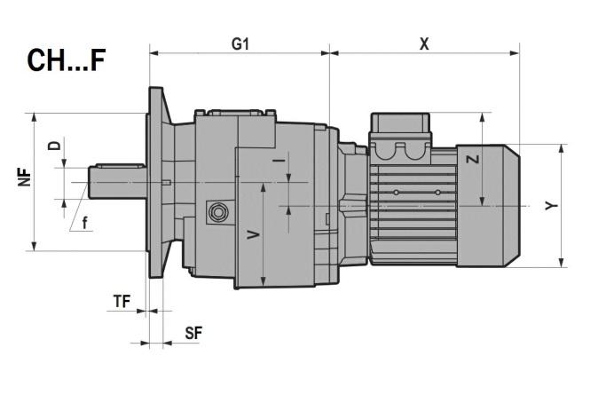
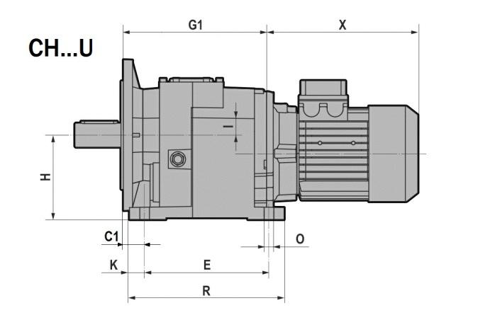
49 H Seres / ATEX / IEC 3.1 REDUCERS/GEARED MOTORS H /F/U/M D B C E F F1 G H H1 I K M N O O2 Q Q1 R R1 S S1 ~V b t f H j , (041M) H j , H j H k (081M) 9 M8x17 (n.5) M8x17 (n.5) M8x17 (n.5) 14 M10x20 (n.7) H k M10x20 (n.6) H m , M12x25 (n.7) ,5 98 9, ,5 M , , M , M M , , ,5 M , M20 H041F/U H051F/U H061F/U H081F/U H101F/U H121F/U FA J J1 M1 M2 NF f8 Ø165 Ø N1 O1 P P1 FB Ø130 Ø Ø160 / 9 3, FC Ø115 Ø Ø140 / 9 3 SF TF Ø ,5 FD Ø100 Ø85 80 M8 Ø120 / 9 3 FA Ø215 Ø Ø FB Ø165 Ø Ø200 / 12 3,5 FA Ø265 Ø Ø FB Ø215 Ø Ø250 / 15 4 FC Ø165 Ø Ø200 / 15 3,5 FA Ø300 Ø Ø FB Ø265 Ø Ø300 / 16 4 FC Ø 215 Ø Ø250 / 16 4 IEC Pm x Dm H041/F/U/M H051/F/U/M H061/F/U/M G2 H081/F/U/M H101/F/U/M H121/F/U/M x14 69,0 / / x19 90,0 70,0 / x24 90,0 70,0 / x28 105,0 85,0 75, x38 / 110,0 100, x42 / / 148, x48 / / 148, x55 / / 185,0 B5 Pm Dm bm tm , , , , , , , , ,3 48

50 H Seres / ATEX / IEC 3.1 REDUCERS/GEARED MOTORS CH..1 49
51 H Seres / ATEX / IEC 3.1 REDUCERS/GEARED MOTORS CH /F/U/M D B C E F F1 G H H1 I K M N O O2 Q Q1 R R1 S S1 ~V b t f CH j , (041M) CH j , CH j CH k (081M) 9 M8x17 (n.5) M8x17 (n.5) M8x17 (n.5) 14 M10x20 (n.7) CH k M10x20 (n.6) CH m , M12x25 (n.7) ,5 98 9, ,5 M , , M , M M , , ,5 M , M20 CH041F/U CH051F/U CH061F/U CH081F/U CH101F/U CH121F/U FA J J1 M1 M2 NF f8 Ø165 Ø N1 O1 P P1 FB Ø130 Ø Ø160 / 9 3, FC Ø115 Ø Ø140 / 9 3 SF TF Ø ,5 FD Ø100 Ø85 80 M8 Ø120 / 9 3 FA Ø215 Ø Ø FB Ø165 Ø Ø200 / 12 3,5 FA Ø265 Ø Ø FB Ø215 Ø Ø250 / 15 4 FC Ø165 Ø Ø200 / 15 3,5 FA Ø300 Ø Ø FB Ø265 Ø Ø300 / 16 4 FC Ø 215 Ø Ø250 / 16 4 T (IE1 - IE2) CH /F/U/M S CH041 CH051 CH061 CH081 CH101 CH L S 132M/L X / / Y / / Z / / X / Y / Z / X / / / Y / / / Z / / / TB (IE1 - IE2) CH /F/U/M S CH041 CH051 CH061 CH081 CH101 CH L S 132M/L X / / Y / / Z / / X / Y / Z / X / / / Y / / / Z / / /

52 H Seres / ATEX / IEC 3.1 REDUCERS/GEARED MOTORS IH..1 51
53 H Seres / ATEX / IEC 3.1 REDUCERS/GEARED MOTORS IH /F/U/M D B C E F F1 G H H1 I K M N O O2 Q Q1 R R1 S S1 ~V b t f IH j , (041M) IH j , IH j IH k (081M) 9 M8x17 (n.5) M8x17 (n.5) M8x17 (n.5) 14 M10x20 (n.7) IH k M10x20 (n.6) IH m , M12x25 (n.7) ,5 98 9, ,5 M , , M , M M , , ,5 M , M20 IH041F/U IH051F/U IH061F/U IH081F/U IH101F/U IH121F/U FA J J1 M1 M2 NF f8 Ø165 Ø N1 O1 P P1 FB Ø130 Ø Ø160 / 9 3, FC Ø115 Ø Ø140 / 9 3 SF TF Ø ,5 FD Ø100 Ø85 80 M8 Ø120 / 9 3 FA Ø215 Ø Ø FB Ø165 Ø Ø200 / 12 3,5 FA Ø265 Ø Ø FB Ø215 Ø Ø250 / 15 4 FC Ø165 Ø Ø200 / 15 3,5 FA Ø300 Ø Ø FB Ø265 Ø Ø300 / 16 4 FC Ø 215 Ø Ø250 / 16 4 G3 B2 IH j M6 IH j M8 IH j M8 IH j M10 IH , k M12 IH , k M12 D2 b2 t2 f2 52
54 H Seres / ATEX / IEC 3.1 REDUCERS/GEARED MOTORS H..2/3 H /F/U D B b t f C C1 E F G G1 H I K M N O O2 Q R S ~V H032/H j M , M8x17 (n.5) H042/H j M M8x17 (n.5) H052/H k M , M8x17 (n.5) H062/H k M M10x20 (n.6) k M12 H082/H k ,5 M ,5 272, , M12x25 (n.7) k M16 H102/H m M ,5 27, M14x28 (n.7) H122/H m ,5 M ,5 376, , M14x30 (n.7) 185, H142/H m M M16x32 (n.7)
55 H Seres / ATEX / IEC 3.1 REDUCERS/GEARED MOTORS...F/U J J1 H032/H033 H042/H043 H052/H053 H062/H063 H082/H083 H102/H103 FA M1 M2 NF f8 Ø165 Ø N1 O1 P P1 FB Ø130 Ø Ø160 / 9 3, FC Ø115 Ø Ø140 / 9 3 SF TF Ø ,5 FD Ø100 Ø85 80 M8 Ø120 / 9 3 FA Ø215 Ø Ø FB Ø165 Ø Ø200 / 12 3,5 FA Ø265 Ø Ø FB Ø215 Ø Ø250 / 15 4 FC Ø165 Ø Ø200 / 15 3,5 FA Ø300 Ø Ø FB Ø265 Ø Ø300 / 16 4 FC Ø215 Ø Ø250 / 16 4 FA Ø350 Ø Ø FB Ø300 Ø Ø350 / 18 5 FC Ø265 Ø Ø300 / 18 4 H122/H123 FB Ø350 Ø Ø400 / 18 5 H142/H143 FB 22,5 Ø400 Ø Ø450 / FC 45 Ø350 Ø Ø400 / 25 5 IEC Pm x Dm H032/H033 H042/H043 H052/H053 H062/H063 H082/H083 G2 H /F/U H102/H103 H122/H123 H142/H x11 57,0 / / / x14 69,0 49,0 / / x19 90,0 70,0 60,5 / x24 90,0 70,0 60,5 / x28 105,0 85,0 75,5 / x38 / 110,0 100,5 76, x42 / 157,5 148,0 123, x48 / 157,5 148,0 123, x55 / / 185,0 160, x60 / / / 160,5 B5 Pm Dm bm tm , , , , , , , , , , ,4 54

56 H Seres / ATEX / IEC 3.1 REDUCERS/GEARED MOTORS CH..2/3 55
57 H Seres / ATEX / IEC 3.1 REDUCERS/GEARED MOTORS CH /F/U D B b t f C C1 E F G G1 H I K M N O O2 Q R S ~V CH032/CH j M , M8x17 (n.5) CH042/CH j M M8x17 (n.5) CH052/CH k M , M8x17 (n.5) CH062/CH k M M10x20 (n.6) k M12 CH082/CH k ,5 M ,5 272, , M12x25 (n.7) k M16 CH102/CH m M ,5 27, M14x28 (n.7) CH122/CH m ,5 M ,5 376, , M14x30 (n.7) 185, CH142/CH m M M16x32 (n.7) F/U J J1 CH032/CH033 CH042/CH043 CH052/CH053 CH062/CH063 CH082/CH083 CH102/CH103 FA M1 M2 NF f8 Ø165 Ø N1 O1 P P1 FB Ø130 Ø Ø160 / 9 3, FC Ø115 Ø Ø140 / 9 3 SF TF Ø ,5 FD Ø100 Ø85 80 M8 Ø120 / 9 3 FA Ø215 Ø Ø FB Ø165 Ø Ø200 / 12 3,5 FA Ø265 Ø Ø FB Ø215 Ø Ø250 / 15 4 FC Ø165 Ø Ø200 / 15 3,5 FA Ø300 Ø Ø FB Ø265 Ø Ø300 / 16 4 FC Ø215 Ø Ø250 / 16 4 FA Ø350 Ø Ø FB Ø300 Ø Ø350 / 18 5 FC Ø265 Ø Ø300 / 18 4 CH122/CH123 FB Ø350 Ø Ø400 / 18 5 CH142/CH143 FB 22,5 Ø400 Ø Ø450 / FC 45 Ø350 Ø Ø400 / 25 5 T (IE1 - IE2) CH /F/U S CH032/CH033 CH042/CH043 CH052/CH053 CH062/CH063 CH082/CH083 CH102/CH103 CH122/CH L S 132M/L X / / Y / / Z / / X / Y / Z / X / / / Y / / / Z / / / TB (IE1 - IE2) CH /F/U S CH032/CH033 CH042/CH043 CH052/CH053 CH062/CH063 CH082/CH083 CH102/CH103 CH122/CH L S 132M/L X / / Y / / Z / / X / Y / Z / X / / / Y / / / Z / / /
58 H Seres / ATEX / IEC 3.1 REDUCERS/GEARED MOTORS IH..2/3 IH /F/U D B b t f C C1 E F G G1 H I K M N O O2 Q R S ~V IH032/IH j M , M8x17 (n.5) IH042/IH j M M8x17 (n.5) IH052/IH k M , M8x17 (n.5) IH062/IH k M M10x20 (n.6) k M12 IH082/IH k ,5 M ,5 272, , M12x25 (n.7) k M16 IH102/IH m M ,5 27, M14x28 (n.7) IH122/IH m ,5 M ,5 376, , M14x30 (n.7) 185, IH142/IH m M M16x32 (n.7)
59 H Seres / ATEX / IEC 3.1 REDUCERS/GEARED MOTORS...F/U J J1 IH032/IH033 IH042/IH043 IH052/IH053 IH062/IH063 IH082/IH083 IH102/IH103 FA M1 M2 NF f8 Ø165 Ø N1 O1 P P1 FB Ø130 Ø Ø160 / 9 3, FC Ø115 Ø Ø140 / 9 3 SF TF Ø ,5 FD Ø100 Ø85 80 M8 Ø120 / 9 3 FA Ø215 Ø Ø FB Ø165 Ø Ø200 / 12 3,5 FA Ø265 Ø Ø FB Ø215 Ø Ø250 / 15 4 FC Ø165 Ø Ø200 / 15 3,5 FA Ø300 Ø Ø FB Ø265 Ø Ø300 / 16 4 FC Ø215 Ø Ø250 / 16 4 FA Ø350 Ø Ø FB Ø300 Ø Ø350 / 18 5 FC Ø265 Ø Ø300 / 18 4 IH122/IH123 FB Ø350 Ø Ø400 / 18 5 IH142/IH143 IH /F/U FB 22,5 Ø400 Ø Ø450 / FC 45 Ø350 Ø Ø400 / 25 5 G3 G4 B2 IH032/IH j M8 IH042/IH j M8 IH052/IH j M8 IH062/IH j M10 IH082/IH ,5 385, j M10 IH102/IH ,5 442, k M12 IH122/IH k M12 IH142/IH k M16 D2 b2 t2 f2 58
60 H Seres / ATEX / IEC 3.2 ELECTRIC MOTORS Electrc motors AC AD L LB LC X Y V D E E1 f F1 GA F GD , j6 23 1,5 M4x10 2,5 12, ,5 208, ,5 14 j6 30 2,5 M5x S L ,5 *(296) 298 *(331) 323 *(356) 232,5 *(256) 248 *(281) 273 *(306) 314 *(337) 349,5 *(381) 374,5 *(408) j6 40 1,5 M6x , ,5 24 j6 50 1,5 M8x ,5 24 j6 50 1,5 M8x , ,5 28 j6 60 3,5 M10x22 7, ,5 *(408) 322,5 *(348) 447 *(472) j6 60 3,5 M10x22 7, S , ,5 38 k M12x L , ,5 38 k M12x S / ,5 42k6 100 / M16x *TP80B4,TP90S4, TP90L4, TP90S6, TP112M4, TP112M6 B5 M N P LA S T ,5 3, , , , , ,5 3,5 B14 M N P LA S T M5 2, ,5 M6 2, ,5 M ,5 M M8 3, ,5 M8 3, ,5 M10 3, M
61 H Seres / ATEX / IEC 3.2 ELECTRIC MOTORS AC AD L LB X D E f GA F GD 160M M M40x1,5 1-M16x1,5 160L M M40x1,5 1-M16x1,5 180M M16 51, M40x1,5 1-M16x1,5 180L M16 51, M40x1,5 1-M16x1,5 200L M M50x1,5 1-M16x1,5 225S M M50x1,5 1-M16x1,5 225M M M50x1,5 1-M16x1,5 250M M M63x1,5 1-M16x1,5 250M M M63x1,5 1-M16x1,5 280S M M63x1,5 1-M16x1,5 280S M20 79, M63x1,5 1-M16x1,5 280M M M63x1,5 1-M16x1,5 280M M20 79, M63x1,5 1-M16x1,5 B5 M N P LA S T LL Pg 60
62 H Seres / ATEX / IEC 3.2 ELECTRIC MOTORS Standard hgh effcency (TS), hgh (TH) and premum- (TP) motors Motovaro, three-phase, sngle polarty motors are avalable n three dfferent versons (IE1-IE2-IE3) n complance wth standard (see table). The effcency value s calculated accordng to the method set forth n standard IEC IE1: Standard effcency TS seres. 2. IE2: Hgh effcency TH seres 3. IE3: Premum effcency TP seres. Table of Motovaro commercal avalablty EFFICIENCY LEVEL NOMINAL POWER POLES IE1 IE2 IE3 0,09 Pn < 0, TS-TBS - - 0,75 Pn 11 4 TBS - - 0,75 Pn 5,5 6 TBS TH-TBH TP-TBP 0,75 Pn 9,2 4 - TH-TBH - 0,75 Pn 7, TP-TBP 7,5 Pn 22 6 TBS (*) - TP 11 Pn TP 15 Pn 55 4 TBS (*) - - (*) Seres avalable on request. 61
63 H Seres / ATEX / IEC 3.2 ELECTRIC MOTORS Nomnal power - Poles 63A 63B 63C 71A 71B 71C 80A 80B TS TS TS TS TS TS 4 0,12 0,18 0,22 0,25 0,37 0,55 0, ,75 0,75 6 0,09 0,12 0,15 0,18 0,25 0,37 0, , Poles TH 90S 90L 100LR 100L 100LA 112MR 112MS 112MA 112M TP TH TP TP TP 4 1,1 1,1 1,5 1, ,2 2,2 2, ,75 0,75-1,1 1,5 1, ,2 2,2 Poles 112MR 112MS 132S 132SA 132MS 132SB 132M 132MA 132MB TP TP TP TH 4 2,2 3-5,5 5,5-7,5 7,5-9, ,5 5,5 Poles TP TH 160M 160MA 160MB 160L 160LA 180M 180L TP TP TP , , Poles 200L 200LA 200LB 225S 225M 250M 280S 280M TP TP TP , TP TP TS TP TH TP TH TP TP TP TP TP TS TP TH TP TP TP TH TH TH TP TP TP TP TP 62
64 H Seres / ATEX / IEC 3.3 WEIGHT The values reported n the tables are referred to the weght of the gearbox wth lubrcant excluded. * H-PH A31 1,9 2,0 2,2 / / / / / A32 4,2 4,3 4,6 / / / / / A33 4,0 4,1 5,2 / / / / / A41 3,1 3,2 3,5 / / / / / A42 5,2 5,3 5,5 / / / / / A43 5,8 5,9 6,1 / / / / / A51 4,2 4,3 4,5 / / / / / A52 / / 9,5 13,0 / / / / A53 9,9 10,0 10,2 / / / / / A61 / / 6,6 7,0 / / / / A62 / / 11,3 14,8 / / / / A63 12,5 12,6 13,2 / / / / / ,4 8,8 9,4 13,7 / / / / ,9 11,3 11,9 16,2 / / / / 041 / 4,8 5,4 / / / / / ,0 16,4 17,0 21,3 / / / / 051 / 6,7 7,3 11,6 / / / / / 27,0 29,1 31,2 33,9 / / / 061 / / 9,3 13,6 / / / / / / 49,1 51,2 53,2 60,5 / / 081 / / 19,3 21,3 23,9 / / / / / 77,6 79,9 82,7 88,7 / / 101 / / / 32,7 35,5 41,5 / / 121 / / / / 36,8 42,8 57,8 / / / / 109,5 112,3 118,3 133,3 / / / / / 177,0 184,9 199,1 200,9 ~ kg IH ~ kg A32 4,3 A33 5,0 A41 3,3 A42 5,2 A43 5,8 A51 4,2 A52 9,4 A53 9,9 A61 6,5 A62 11,2 A63 12, , , , , , , , , , , , , , ,1 63
65 H Seres / ATEX / IEC 3.3 WEIGHT *Weght wthout motor TS TH CH S 090L S 132M CH S 090L S 132M A32 6,9 8,7 12,7 / / / / / / A32 14,4 / / / / / / A33 7,6 9,5 13,5 / / / / / / A33 15,2 / / / / / / A41 5,9 7,8 11,8 / / / / / / A41 13,5 / / / / / / A42 7,8 9,7 13,7 15,6 18,1 / / / / A42 15,4 17,9 20 / / / / A43 8,4 10,3 14,3 16,2 18,7 / / / / A43 16,0 18,5 20,6 / / / / A51 6,2 8,1 12,1 14,0 16,5 / / / / A51 13,8 16,3 18,4 / / / / A52 / / 17,2 19,1 21,6 26,2 36,5 / / A52 18,9 21,5 23,6 28,5 39,6 / / A53 12,0 13,9 17,9 19,8 22,3 / / / / A53 19,6 22,1 24,3 / / / / A61 / / 14,3 16,2 18,7 23,3 33,6 / / A61 16,0 18,6 20,7 25,6 36,7 / / A62 / / 19,2 21,1 23,6 28,2 38,5 / / A62 20,9 23,4 25,6 30,5 41,6 / / A63 14,6 16,5 20,5 22,4 24,9 / / / / A63 22,1 24,7 26,8 / / / / ,9 12,8 17,5 21,4 23,4 28,9 40,4 / / ,4 15,3 20,0 23,9 25,9 31,4 42,9 / / ~ kg ,2 23,7 25,3 31,2 43,5 / / ,7 26,3 27,9 33,8 46 / / ~ kg 041 / 8,8 13,5 17,4 19,4 / / / / ,2 19,7 21,3 / / / / ,5 20,4 25,1 29,0 31,0 36,5 48,0 / / ,8 31, ,9 51,1 / / 051 / 10,7 15,4 19,3 21,3 26,8 38,3 / / ,1 21,6 23,2 29,1 41,4 / / / 32,7 37,8 40,2 41,7 46,8 58,2 72,2 83, ,5 42,5 43,7 49,1 61,3 77,5 90,6 061 / / 17,4 21,3 23,3 28,8 40,3 / / ,1 23,6 25,2 31,1 43,4 / / / / 59,7 62,1 63,6 68,7 80,1 94,1 105, ,4 64,4 65, ,2 99,4 112,5 081 / / 27,1 29, ,1 47,5 61,5 73, ,8 31, ,4 50,6 66,8 79, / / / 93,8 94,8 100,8 110,8 125,8 134, / 96,1 96,8 103,1 113,9 131,1 141,6 101 / / / / / 49,6 59,6 74,6 83,6 101 / / / 51,9 62,7 79,9 90,4 121 / / / / / / / / / / / / 82,3 92, / / / / / 134,5 144,5 159,5 168, / / / 136,8 147,6 164,8 175,3 TBS TBH CH S 090L S 132M CH S 090L S 132M A32 8,2 10,6 15,8 / / / / / / A32 17,5 / / / / / / A33 8,9 11,4 16,6 / / / / / / A33 18,3 / / / / / / A41 7,2 9,7 14,9 / / / / / / A41 16,6 / / / / / / A42 9,1 11,6 16,8 20,5 23,0 / / / / A42 18,5 22,8 25,0 / / / / A43 9,7 12,2 17,4 21,1 23,6 / / / / A43 19,1 23,4 25,6 / / / / A51 7, ,2 18,9 21,4 / / / / A51 16,9 21,2 23,4 / / / / A52 / / 20,3 24,3 26,5 31,1 44,8 / / A ,6 28,5 34,8 47,9 / / A53 13,3 15, ,7 27,2 / / / / A53 22, ,2 / / / / A61 / / 17,4 21,1 23,6 28,2 41,9 / / A61 19,1 23,4 25,6 31,9 45 / / A62 / / 22, ,5 33,1 46,8 / / A ,3 30,5 36,8 49,9 / / A63 15,9 18,4 23,6 27,3 29,8 / / / / A63 25,3 29,6 31,8 / / / / , ,9 28,9 34,4 50,1 / / ,9 17,5 23,5 29,4 31,4 36,9 52,6 / / ~ kg ,7 29,2 30,9 38,1 53,2 / / ,2 31,7 33,4 40,6 55,7 / / ~ kg 041 / ,9 24,9 / / / / ,6 25,2 26,9 / / / / ,0 22,6 28,6 34,5 36, ,7 / / ,3 36,9 38,6 45,8 60,9 / / 051 / 12,9 18,9 24,8 26,8 32,3 48 / / ,6 27,1 28, ,1 / / / 34,9 41,3 45,7 47,2 52,3 67,9 82,5 98, , , / / 20,9 26,8 28,8 34,3 50 / / ,6 29,1 30, ,1 / / / / 63,2 67,6 69,1 74,2 89,8 104,4 120, ,9 69,9 71,1 77,9 92,9 109,7 126,9 081 / / 30, ,5 41,6 57,2 71,8 87, ,3 37,3 38,5 45,3 60,3 77,1 94, / / / 99,4 100,4 106,4 120,6 136,2 149, / 101,7 102,4 110,1 123,7 141,5 156,1 101 / / / / / 55 69, ,3 101 / / / 58,7 72,4 90,3 104,8 121 / / / / / / / 87,3 100,7 121 / / / / / 92,6 107, / / / / / ,2 169,8 183, / / / 143,7 157,3 175,1 189,7 64

66 H Seres / ATEX / IEC 3.4 END SHAFT UNI DIN 6885 d b x h Tol. b / h L s mn / max b t1 t2 Tol. t1 / t2 r max ,2 1 > ,16 0,25 3 1,8 1,4 > h9 / h ,5 1,8 > ,3 > ,25 0, ,8 > ,3 0,1 0 0,08 0,16 0,16 0,25 > ,3 > ,3 > ,4 0,6 14 5,5 3,8 > ,3 > ,4 > ,5 4,9 h9 / h11 > ,4 > ,6 0, ,4 > ,4 > ,4 > ,4 > , ,4 > ,4 0,2 0 0,3 0 0,25 0,4 0,4 0,6 0,7 1 65

67 H Seres / ATEX / IEC 4.1 OUTPUT FLANGE H...F/H...U 032/ / / / / / / /143 FA FB FC FD FA FB FC FA FB FC FA FB FC FA FB FC FA FB FC FA FB FC 66

68 H Seres / ATEX / IEC 4.2 BACKSTOP DEVICE The gear reducer can be suppled wth backstop devce on nput shaft. Backstop devce allows output shaft rotaton n only one sense of drecton; accordng to the sze, t s avalable n the nput flange or n the motor wth the same dmensons. It s mportant to specfy the requred sense of drecton on the order. It s devce s not avalable for mountng poston V1/V5 wth motor sze IEC Certfed accessory for ATEX 3G/3D, only. SENSE OF DIRECTION AVAILABLE x11 160x14 200x19 200x24 250x28 H032 B5 B5 B5 B5 H033 B5 B5 B5 B5 H041 B5 B5 B5 H042 B5 B5 B5 B5 H043 B5 B5 B5 B5 H051 B5 B5 B5 B5 H052 B5 B5 B5 B5 H053 B5 B5 B5 B5 H061 B5 B5 B5 300x38 H062 B5 B5 B5 B5 H063 B5 B5 B5 B5 H081 B5 B5 B5 B5 350x42 H082 B5 B5 B5 B5 B5 H083 B5 B5 B5 B5 350x48 H101 B5 B5 B5 B5 H102 B5 B5 B5 B5 H103 B5 B5 B5 B5 H121 B5 B5 B5 B5 H122 B5 B5 B5 B5 H123 B5 B5 B5 B5 B5 400x55 H142 B5 B5 B5 B5 H143 B5 B5 B5 B5 450x60 67
69 H Seres / ATEX / IEC 4.3 THERMAL PROTECTOR It s a PTC probe (see Fg. 1) wth a trgger temperature of 120 C. The customer shall perform the electrc connecton to the man electrc panel to ensure the resstance thermometer correct operaton regardless of the connectons necessary for the system operaton. The connecton must apply the postve safety logc. Man powerboard, connectons and logc must, taken together, provde a lockng system to prevent, n the event of a shutdown, the unwanted start-up of the devce. In case of nterventon of the PTC probe, wat about 10 mn. before resettng the man powerboard. Unt electrc characterstcs: Power to sensor <280 mw Voltage to sensor <30 Vdc Current to sensor <8 ma Fg.1 - PTC probe Connecton 68

 n V1/ V5 mountng poston, are already equpped wth 2 ol seals as standard.")
70 H Seres ATEX IEC 4.4 REINFORCED OIL SEALS FOR OUTPUT SHAFT The renforced seal can be done dependng on the gearbox sze by means of two ol seals or through the standard ol seal wth VRM rng. The dfference of the two solutons s explaned on the drawngs. The helcal gear reducers from sze 060 to sze 140 (except for sngle stage) n V1/ V5 mountng poston, are already equpped wth 2 ol seals as standard. On request the gear reducer can be suppled wth fluoroelastomer FPM (FKM) seals. Double ol seal VRM rng H041 X H051 X H061 X H081 X H101 X H121 X H032/3 X H042/3 X H052/3 X H062/3 X H082/3 X H102/3 X H122/3 X H142/3 X 69
TECHNICAL CATALOGUE H / IEC / STD / EN / REV.0 / 2017 HELICAL GEAREDMOTORS STANDARD IEC
 H / IEC / STD / EN / REV.0 / 2017 HELICAL GEAREDMOTORS STANDARD IEC H Seres / Standard / IEC INDEX 1. GENERAL INFORMATION 1.1 SYMBOLS AND FORMULAS 4 1.1.1 Symbols 4 1.1.2 Formulas 5 1.2 PRODUCT SELECTION
TECHNICAL CATALOGUE GEAREDMOTORS STANDARD IEC DIRECTIVE ATEX
 HELICALBEVEL GEAREDMOTORS STANDARD IEC DIRECTIVE ATEX B Seres / ATEX / IEC INDEX 1. GENERAL INFORMATION 1.1 ATEX 4 1.2 SYMBOLS AND FORMULAS 5 1.2.1 Symbols 5 1.2.2 Formulas 6 1.3 PRODUCT SELECTION 7 1.4
Helical geared motors SERIES
 H SERIES Informaton Contents Symbols... Modularty... Desgn features... Product selecton gude... Servce factor... Crtcal applcatons... Thermal power... Installaton... Motor mountng wth PAM flange... Overhung
HELICALBEVEL GEAREDMOTORS
 B / IEC / STD / EN / REV.0 / 2017 HELICALBEVEL GEAREDMOTORS STANDARD IEC B Seres / Standard / IEC INDEX 1. GENERAL INFORMATION 1.1 SYMBOLS AND FORMULAS 4 1.1.1 Symbols 4 1.1.2 Formulas 5 1.2 PRODUCT SELECTION
TECHNICAL CATALOGUE VSF / IEC / STD / EN / REV.0 / 2017 WORM GEAREDMOTORS STANDARD IEC
 VSF / IEC / STD / EN / REV.0 / 2017 WORM GEAREDMOTORS STANDARD IEC INDEX 1. GENERAL INFORMATION 1.1 SYMBOLS AND FORMULAS 5 1.1.1 Symbols 5 1.1.2 Formulas 6 1.2 PRODUCT SELECTION 7 1.3 SERVICE FACTOR 8
Worm gear reducers and Worm geared motors VSF SERIES NMRV
 VSF SERIES Worm gear reducers and Worm geared motors NMRV Contents Symbols... Specfcaton... Modularty... Servce factor... Crtcal applcatons... Installaton... Overhung load ()... Moments of nerta... Lubrcaton...
Products in the range
 WORM GEAR UNITS & GEAR MOTORS SERIES V Products n the range Servng a great qualty and hgh effcency of gear drves, transmsson components, electrc motors, varable speed drves, startng and stoppng assstng
GEARED VANE AIR MOTORS. Type Ratio Version Output shaft Torque arm Optins
 2 TECHNICAL FEATURES The man features of worm gearboxes used are: Alumnum housng Double taper roller bearng on sze 090 and 110. Permanent synthetc ol long-lfe lubrcaton Desgnaton GEARED VANE AIR MOTORS
Z-50-S Standing Spindle 50 kn
 Z-50-S Standng Spndle 50 kn Safety Safety nut nut New: Spndle lubrcaton durng operaton Ths page Secton.29 Secton.27 M12/16 deep 52J7/ deep M10/15 deep SRO Length M12/16 deep Fttng heght Y Overall heght
Compact Motor Geared Motors
 Compact Geared s Compact CIM-2.01GB0914 PRODUCTS IN THE RANGE Servng an entre spectrum of mechancal drve applcatons from food, energy, mnng and metal; to automotve, aerospace and marne propulson, we are
HSERIES. Helical geared motors
 HSERIES Helical geared motors Design features Motovario products are supplied with the following surface treatment features: Die-cast aluminium alloy cases for gears Die-cast materials undergo the following
Operating Instructions Pneumatic drives
 Operatng Instructons Pneumatc drves Pneumatc drves Equpment characterstcs Poston ndcator (detachable)! Settng screw for pvot angle 1 4 5 Ar nterface accordng to VDI / VDE 3845 (Namur) Advantages of the
Product Information. Universal swivel vane RM-W
 Product Informaton RM-W RM-W Modular. Compact. Flexble. RM-W swvel vane wth hgh torque for fast swvelng tasks Feld of applcaton To be used n clean to slghtly drty envronments such as assembly or packagng
Stromag. Electromagnetic Fail Safe Brakes Series NFA/NFF. Versions: Basic & Dockside Cranes. Stromag Limited
 Stromag Electromagnetc Fal Safe Brakes Seres NFA/NFF Versons: Basc & Docksde Cranes Stromag Lmted 29 Wellngborough Road,Rushden Northamptonshre NN10 9YE Unted Kngdom Tel. 01933 350407 Fax. 01933 358692
Product Information. Angular parallel gripper GAP
 Product Informaton GAP GAP More flexble Productve. Narrower. GAP angular parallel grpper 2-fnger angular parallel grpper wth grpper fnger actuaton of up to 90 degrees per jaw Feld of applcaton Grppng and
IPV High-pressure Internal Gear Pumps Technical Data Sheet
 IV Hgh-pressure Internal ear umps Techncal Data Sheet Functon 1 7 5 9 2 10 8 2 1 9 4a 4b 3 1 non shaft 2 Internal gear 3 Fller pn 4a Fller segment carrer 4b Fller sealng segment 5 Axal dsc Axal pressure
102 ALUFIX CLAMPING ELEMENTS
 102 103 ALUFIX CLASSIC Clampng Elements Alufx clampng elements fx workpeces to fxtures and ensure contact wth support surfaces 104 ØB ØA 3 Jaw Keyless Chuck for measurng applcatons D C Nr. A B C D 82220
Product Information. Universal swivel finger GFS
 Product Informaton GFS GFS Productve. Flexble. Compact. GFS unversal rotary fnger Rotary fnger for turnng workpeces that are held by a grpper or can also be used as a specal swvel unt. Feld of applcaton
Product Information. Miniature swivel Head SKE
 Product Informaton SKE SKE Compact. Fast. Productve. SKE mnature swvel head 90 swvel head wth sngle pston drve Feld of applcaton For use n clean envronments such as assembly or packagng zones and for lght
Loadable. Flexible. Robust. Universal Rotary Unit PR
 PR Electrcal Rotary Unts Unversal Rotary Unt Loadable. Flexble. Robust. Unversal Rotary Unt PR Servo-electrc rotary unt wth angle > 360, precson gear and ntegrated electroncs Feld of Applcaton All-purpose,
Mounting and Operating Instructions Bevel Gearboxes KEK
 Mountng and Operatng Instructons Bevel Gearboxes KEK Responsble MÄDLER branches accordng to German Post Code Areas: For Swtzerland: PCA 1, 2 and 3 PCA 0, 4 und 5 PCA, 7, 8 und 9 MÄDLER Norm-Antreb AG Subsdary
Product Information. Radial gripper DRG
 Product Informaton Radal grpper DRG DRG Radal grpper Fully encapsulated. Narrower. More flexble DRG sealed grpper Sealed 180 angular grpper for the use n contamnated envronments Feld of applcaton For applcatons
PRODUCTS IN THE RANGE
 Seres 0311 PRODUCTS IN THE RANGE Servng an entre spectrum of mechancal drve applcatons from food, energy, mnng and metal; to automotve, aerospace and marne propulson, Textron Power Transmsson s here to
Product Information. Gripper for small components KGG 60
 Product Informaton KGG More compact. More flexble Narrower. KGG grpper for small components narrow 2-fnger parallel grpper wth long stroke Feld of applcaton for unversal use n clean envronments wth lght
AXO Adjustable Vanes High Induction Swirl Diffusers
 Ar Dffuson 13 AXO Adjustable Vanes Hgh Inducton Swrl Dffusers H V A C TM Archtecture, Comfort, Effcency Rev 27-05-2018 Ar Dffuson 14 AXO SEres Adjustable Vanes Round Swrl Dffusers Indvdually adjustable
Operating Manual for the Battery Powered Hydraulic Pump Kit READ THIS FIRST! customer manual TOOLING ASSISTANCE CENTER
 Operatng Manual for the Battery Powered Hydraulc Pump Kt Customer Manual 409-10094 2063680-1 05 JAN 12 SAFETY PRECAUTIONS READ THIS FIRST!............................ 2 customer manual 1. INTRODUCTION.......................................................
Product Information. Gripper for small components MPZ 30
 Product Informaton MPZ Precse. Compact. Relable. MPZ grpper for small components Small 3-fnger centrc grpper wth base jaws guded on T-slots Feld of applcaton for unversal use n clean to slghtly drty workng
Product Information. Radial gripper PRG 64
 Product Informaton PRG 64 PRG More flexble More powerful. Slm. PRG unversal grpper 180 radal grpper wth powerful 1-shft slotted lnk gear and oval pston. Feld of applcaton For areas of applcaton whch, n
SpaceStation TM. Installation Instructions SpaceStation Occupancy Lighting Control System. Please Save These Instructions
 Phone: 605.542.4444 concealte.com! Installaton SpaceStaton Occupancy Lghtng Control System Please Save These Important Safeguards Read and Follow All Safety þdo not use outdoors. þdo not let power supply
Product Information. Long-stroke gripper PZH-plus
 Product Informaton Long-stroke grpper PZH-plus PZH-plus Long-stroke grpper Flexble. Robust. Flat. PZH-plus unversal grpper Unversal grpper wth long travel and hgh maxmum moment due to mult-tooth gudance
Series M Helical In-Line
 Seres Helcal In-Lne Techncal Up to - 90 Kw / 11,000 Nm Geared otors C-2.00GB1211 PRODUCTS IN THE RANGE Servng an entre spectrum of mechancal drve applcatons from food, energy, mnng and metal; to automotve,
SERIES M CONTENTS
 C-3.01INP0316 SERIES CONTENTS General Descrpton Unt Desgnaton Explanaton And Use Of Ratngs And Servce s Classfcaton By Applcatons Selecton Procedure For otorsed Unts Unt Versons Shaft Optons otor Adaptors
Series M Helical In Line Technical Up to 90 kw/11,000 Nm Geared Motors
 www.pbl.co.n Seres Helcal In Lne Techncal Up to 90 kw/11,000 Geared otors SERIES PRODUCTS IN THE RANGE Servng an entre spectrum of mechancal drve applcatons from food, energy, mnng and metal; to automotve,
Series C Helical Worm
 Seres C Helcal Worm Techncal Up to - 45kW / 10,000 Nm Geared otors CC-2.00GB1211 PRODUCTS IN THE RANGE Servng an entre spectrum of mechancal drve applcatons from food, energy, mnng and metal; to automotve,
Ring and Spade Terminals
 J Rng and Spade Termnals Applcaton Specfcaton 114-2084 25 J J AN All numercal values are n metrc unts [wth U.S. customary unts n brackets]. Dmensons are n mllmeters [and nches]. Unless otherwse specfed,
Accessories for Circular Plastic Connectors (CPC)
") Accessores for Crcular Plastc Connectors (CPC) Instructon Sheet 408-7582 14 MAR 11 Sheld and Stran Relef Kt -- Straght Cable Clamp Receptacle Plug Extender 2027055-1 Plug Back of Extender Stran Relef Clamp
Accessores for Crcular Plastc Connectors (CPC) Instructon Sheet 408-7582 14 MAR 11 Sheld and Stran Relef Kt -- Straght Cable Clamp Receptacle Plug Extender 2027055-1 Plug Back of Extender Stran Relef Clamp
Series M Helical In Line
 Engneered around you www.davdbrown.com Seres Helcal In Lne Techncal Up to - 90kW / 110,000 Gear otors C-1.02GBD1009 Каталог мотор-редукторов SERIES Davd Brown / Benzlers Radcon Servng an entre spectrum
Match factor extensions
 Chapter 3 Match factor extensons For the mnng ndustry, the match factor rato s an mportanndcator wth a dual purpose: durng the equpment selecton phase, t can be used to determne an approprate fleet sze
Series C Helical Worm
 Seres C elcal Worm Techncal p to - 60 P / 89,000 lb.n Geared otors CC-2.00S1211 PRODCTS IN TE RANGE Servng an entre spectrum of mechancal drve applcatons from food, energy, mnng and metal; to automotve,
Installation, Operation and Warranty Information Micro Annular Gear Pump MODEL 7205
 Installaton, Operaton and Warranty Informaton Mcro Annular Gear Pump MODEL 7205 1402 NE 136 th Ave. Vancouver, WA 98684 (360) 253-2008 telephone (360) 253-8294 fax Info.mcropump@dexcorp.com www.mcropump.com
Vacuum supply, overview
 64 Vacuum supply Vacuum supply, overvew Vacuum unts Modular vacuum unts ompact vacuum unts Vacuum workstatons Vacuum pumps Lqud rng pumps Vacuum supply 65 Vacuum Supply Pumps Unts Workstatons pplcaton
www. ElectricalPartManuals. com INSTRUCTIONS PNEUMATIC TIMING RELAYS DESCRIPTION MAINTENANCE OPERATION Type AM With or without Auxiliary Switch Units
 FG.. DESCRPTON OPERATON MANTENANCE NSTRUCTONS Type AM Relay Wth One Auxlary Swtch Unt TYPE AM PNEUMATC TMNG RELAYS are for general use where t s desred to open or close electrcal crcuts followng a defnte
Series C Helical Worm
 Seres C Helcal Worm Techncal p to - 45 Kw / 10,000 Nm Geared otors CC-2.01GB0 1 PRODCTS IN THE RANGE Seres A Worm Gear unts and geared motors n sngle & double reducton types Seres BD Screwjack worm gear
SERIES C PRODUCTS IN THE RANGE
 Seres C 0403 PRODUCTS IN THE RANGE Servng an entre spectrum of mechancal drve applcatons from food, energy, mnng and metal; to automotve, aerospace and marne propulson, Textron Power Transmsson s here
Operator's Manual. Battery Pack HS/VS 120. Made in Germany
 Operator's Manual Battery Pack HS/VS 120 Made n Germany 2 Operator's Manual 2 for the followng products Table of Contents Type Battery Pack HS/VS 120 1 Introducton...3 1.1 Product Descrpton...3 Edton:
Source: Holmes Place 142
 142 Source: Holmes Place Mandatory program: flter backwash Your flter ensures a mechancal cleanng of the water from coarse mpurtes (drt, har, skn partcles, etc.) and a recrculaton of the pool water by
Series K Helical Bevel
 www.radcon.com Seres K elcal Bevel Techncal p to - 90kW / 12,300 Nm Gear otors CK-1.02GBD0111 PRODCTS IN TE RANGE Servng an entre spectrum of mechancal drve applcatons from food, energy, mnng and metal;
Series K Helical Bevel
 Seres K Helcal Bevel Techncal Up to- 160 kw / 50,000 Geared otor CK-3.02-GB-0318 PRODUCTS IN THE RANGE Seres A Worm Gear unts and geared motors n sngle & double reducton types Seres BD Screwjack worm gear
EMC3300 ELECTRO-MECHANICAL CRIMP TOOL
 Descrpton The EMC3300 Electro-Mechancal Crmp Tool s a handheld, self contaned crmp tool ntended to crmp contacts/termnals onto copper and alumnum cable. KEEP THIS MANUAL Important Safety Informaton Safety
Product Information. Compact linear module ELP
 Product Informaton ELP ELP Easy. Fast. Relable. ELP compact lnear module Electrc lnear module wth drect drve and ntegrated controller, scope-free guded usng pre-loaded roller gude Feld of applcaton For
TECHNICAL ENQUIRY SPECIFICATION OF BATTERY OPERATED PALLET TRUCK
 BHEL ~.BANGALORE TECHNCAL ENQURY SPECFCATON OF BATTERY OPERATED PALLET TRUCK TRUPAT TRUMALA DEVASTHANA, TTD PALLET..o1 TECHNCAL SPECFCATONS OF BATTERY OPERATED PALLET TRUCK V. Sahadevan ssued by: BGA Oate:
Electrical devices may only be mounted and connected by electrically skilled persons.
 Art. No. : 1711DE Operatng nstructons 1 Safety nstructons Electrcal devces may only be mounted and connected by electrcally sklled persons. Serous njures, fre or property damage possble. Please read and
PRODUCTS IN THE RANGE
 Seres K CAT.K05 PRODCTS IN TE RANGE 0105 Servng an entre spectrum of mechancal drve applcatons from food, energy, mnng and metal; to automotve, aerospace and marne propulson, Textron Power Transmsson s
Mobile fence. Road construction. Event. Mobile fence e. Building construction. Civil engineering. Storage equipment. Transport equipment
 e 48 Urban Equpment Buldng Equpment Standard as barrer around constructon stes, moble fence pre-galvanzed, wth tubular frame all around, vertcal tubes Ø 42.4 mm, horzontal tubes Ø 26.9 mm, mesh sze: vertcal:
Series K Helical Bevel
 Seres K elcal Bevel Techncal p to - 120 P / 109,000 lb.n Geared otors CK-2.00S1211 PRODCTS IN TE RANGE Servng an entre spectrum of mechancal drve applcatons from food, energy, mnng and metal; to automotve,
F Series Shaft Mounted Gear Units
 F Seres Shaft ounted Gear Unts Superor Gear Technology ATEX Complance Assured Total complance wth the ATEX Drectve safeguardng the use of ndustral equpment n potentally explosve atmospheres s assured for
AMP 3K* Terminating Machine [ ] and AMP 5K* Terminating Machine [ ] customer manual TOOLING ASSISTANCE CENTER
![AMP 3K* Terminating Machine [ ] and AMP 5K* Terminating Machine [ ] customer manual TOOLING ASSISTANCE CENTER](/thumbs/89/99583981.jpg "AMP 3K* Terminating Machine [ ] and AMP 5K* Terminating Machine [ ] customer manual TOOLING ASSISTANCE CENTER") AMP 3K* Termnatng Machne 1725950-[ ] and AMP 5K* Termnatng Machne 1725900-[ ] Customer Manual 409-10047 30 JAN 12 customer manual SAFETY PRECAUTIONS READ THIS FIRST!............................ 2 1. INTRODUCTION........................................................
AMP 3K* Termnatng Machne 1725950-[ ] and AMP 5K* Termnatng Machne 1725900-[ ] Customer Manual 409-10047 30 JAN 12 customer manual SAFETY PRECAUTIONS READ THIS FIRST!............................ 2 1. INTRODUCTION........................................................
UNIBOX Series. Enclosures and wiring accessories IP40 - IP55
 Enclosures and wrng accessores IP - IP55 ENCLOSURES AND WIRING ACCESSORIES IP - IP55 GENERAL DESCRIPTION enclosures are desgned to accomodate EVOLUTION Seres accessores and, wth specfc bearng adaptors,
SERIES K CONTENTS PAGE
 CONTENTS PAGE General Descrpton 1 Unt Desgnaton 2 Explanaton And Use Of Ratngs And s 3 Classfcaton By Applcatons 4 Selecton Procedure For sed Unts 5-6 Optons 7-8 Adapters 9-10 Lubrcaton 11 ountng Posstons
Series K (Helical Bevel) CK-1.01GBD0308. Technical Up to - 90 kw / 12,300 Nm GEAR MOTORS.
 CK-1.01GBD0308. Technical Up to - 90 kw / 12,300 Nm GEAR MOTORS.") CK-1.01GBD0308 Seres K (elcal Bevel) Techncal p to - 90 kw / 12,300 Nm GEAR OTORS www.davdbrown.com PRODCTS IN TE RANGE Servng an entre spectrum of mechancal drve applcatons from food, energy, mnng and
CK-1.01GBD0308 Seres K (elcal Bevel) Techncal p to - 90 kw / 12,300 Nm GEAR OTORS www.davdbrown.com PRODCTS IN TE RANGE Servng an entre spectrum of mechancal drve applcatons from food, energy, mnng and
Solar Thermal Flat Plate Collectors FKT-1 Rack System for Flat Roof and Wall Installation
 63043970.0-.SD Solar Thermal Flat Plate Collectors FKT- Rack System for Flat Roof and Wall Installaton US/CA Installaton Manual for Contractors 2 Contents US General..................................................
Series K Helical Bevel
 Seres K Helcal Bevel Techncal Up to - 90 kw / 12,300 Nm Geared otors CK-2.00GB1211 ATEX Complance Assured Total complance wth the ATEX Drectve safeguardng the use of ndustral equpment n potentally explosve
FKT SERIES FLAT PANEL SOLAR COLLECTORS ROOF MOUNTING FOR WORCESTER SOLAR HEATING SYSTEMS
 FKT SERIES FLAT PANEL SOLAR COLLECTORS ROOF MOUNTING FOR WORCESTER SOLAR HEATING SYSTEMS 60966.0-.SD G Installaton nstructons About ths manual Ths nstallaton manual contans mportant nformaton for the safe
Series K Helical Bevel
 Seres K elcal Bevel Techncal p to - 160 kw / 50,000 Nm Geared otors CK-3.00GB0813 ATEX Complance Assured Total complance wth the ATEX Drectve safeguardng the use of ndustral equpment n potentally explosve
General Description. Construction
 Sheet 0 General Descrpton.- MEB Metal-Enclosed Drawout General Descrpton Eaton s Cutler-Hammer MEB (Metal- Enclosed ) conssts of a sngle hgh drawout vacuum crcut breaker (Type VCP-W) n a metal-enclosed
Metal-Enclosed Switchgear MEB & MSB Medium Voltage Switch and Fixed Mounted Vacuum Breakers (MSB) MSB Metal-Enclosed Switch and Vacuum Breaker
 MSB Metal-Enclosed Switch and Vacuum Breaker") June 0 Sheet 0 Metal-Enclosed Swtchgear MEB & MSB Medum Voltage Swtch and Fxed Mounted Vacuum s (MSB) General Descrpton.- MSB Metal-Enclosed Swtch and Vacuum General Descrpton Eaton s Cutler-Hammer assembly
June 0 Sheet 0 Metal-Enclosed Swtchgear MEB & MSB Medum Voltage Swtch and Fxed Mounted Vacuum s (MSB) General Descrpton.- MSB Metal-Enclosed Swtch and Vacuum General Descrpton Eaton s Cutler-Hammer assembly
RTMR ORDERING OPTIONS
 RTMR ORDERING OPTIONS There are many dfferent ways to order the RTMR block and matchng accessores. You can buy ndvdual parts separately so you can mx & match to sut your exact requrements, or you can buy
INDEX. Technical characteristics pag Efficiency - Irreversibility pag. 4 Mesh data pag. 5. Lubrication pag. 6 Mounting Position pag.
 B OX S E R I E S W O R M G E A R U N I T S INDEX Techncal characterstcs pag. - Effcency - Irreversblty pag. 4 Mesh data pag. 5 Lubrcaton pag. 6 Mountng Poston pag. 7 Stado pag. 4 Boxstado pag. 5 performance
Panel & Drywall Lifting Material Transport Door Installation Overhead Drilling
 MATERIAL HANDLING SOLUTIONS Panel & Drywall Lftng Materal Transport Door Installaton Overhead Drllng Access Platform Sales (APS) offers a range of manual handlng solutons desgned to move materals safely
Busway Power Distribution
 Buswa Power Dstrbuton BD Plug-In ( - -1 Ampere) SELECTION -1 Amperes Cable Tap Box End Closure Hangers End Prces Center Alumnum 3 Phase, 3 Wre EBA302 EBA304 EBA306 EBA308 EBA310 EBA3 1190. 1430. 2110.
R 1000 Modular shelving system
 MODULAR SHELVING SYSTEMS GALVANISED LIGHT GREY RAL 7035 RAL 7035 R 1000 Modular shelvng system The advantages of modular shelvng from SSI SCHAEFER are mpressve: Closed sold sde panels prevent stored goods
Product Information. Universal rotary unit ERS
 Product Informaton Compact. Flexble. Fast. Electrcal rotary unt wth torque motor and angle of rotaton > 360 as well as the pneumatc holdng brake and rotary feed-through optons, and f desred ncreased protecton
Features & Design. Introduction
 GREASE MANAGEMENT Introducton astewater from commercal ktchens s contamnated wth FGS (fats, ols and greases). The ntroducton of FGs and food solds nto the general dranage/sewage system (ether man sewage
Features & Design. Introduction
 & n the Introducton astewater from commercal ktchens s contamnated wth FGS (fats, ols and greases). The ntroducton of FGs and food solds nto the general dranage/sewage system (ether man sewage network
ANALYSIS OF THE PLANETARY GEAR OF RAVIGNEAUX TYPE AND ITS APPLICATION IN AGRICULTURAL TRACTORS
 TEKA Kom. Mot. Energ. Roln. OL PAN, 7, 7, ANALYSIS OF THE PLANETARY GEAR OF RAVIGNEAUX TYPE AND ITS APPLICATION IN AGRICULTURAL TRACTORS Jery śebrowsk*, Zbgnew śebrowsk** Unversty of Warma and Maury n
1.15 Instrument Cluster (IC) Contents
 Contents") 1.15 Instrument Cluster (IC) Contents 1.15 Model 163 (as of M.Y. 1998) wth FSS Dagnoss Functon Test................................... 11/1 Dagnostc Trouble Code (DTC) Memory................ 12/1 Complant
1.15 Instrument Cluster (IC) Contents 1.15 Model 163 (as of M.Y. 1998) wth FSS Dagnoss Functon Test................................... 11/1 Dagnostc Trouble Code (DTC) Memory................ 12/1 Complant
Air Driven Hydraulic Pumps
 XA-Seres Ar Drven Hydraulc Pumps The breakthrough n hydraulc pump technology & ergonomcs. 700 bar pumps wth XVARI Technology, exclusvely from Enerpac! Ergonomc desgn for less operator fatgue Varable ol
CONSTRUCTION SPECIFICATION FOR WATERMAIN AND WATER SERVICE TRACER WIRE INDEX. SUBMISSION AND DESIGN REQUIREMENTS Not Used...2
 CITY OF TORONTO TORONTO WATER STANDARD CONSTRUCTION SPECIFICATIONS TS 7.40 February 2006 TS 7.40.01 CONSTRUCTION SPECIFICATION FOR WATERMAIN AND WATER SERVICE TRACER WIRE INDEX GENERAL...2 TS 7.40.01.01
Master Connection Diagram Series C R-Frame Circuit Breaker with DIGITRIP RMS Trip Units
 nstruction Leaflet L29C714L Supersedes L 29C714K Dated 01/12 Circuit Breaker with DGTRP RMS Trip Units nstruction Leaflet L29C714L Circuit Breaker with DGTRP RMS Trip Units LNE 1 2 3 NDEX DAGRAMS TRP UNT
Operating Instructions Electromagnetic clutch-brake combinations
 Operatng Instructons Electromagnetc clutch-brake combnatons 14.800/14.810 j settng the standard www.ntorq.de Ths documentaton s vald for: 14.800.06 14.810.06 14.800.08 14.810.08 14.800.10 14.810.10 14.800.12
THE ROTH REGENERATIVE TURBINE MAGNETIC DRIVE PUMP
 Bul l et nm105r3 Rot hseal l ess OneFootNPSHr Regener at vetur b nemagnet cdr vepumps ForCont nuoush ghpr essur epump ngofl quef edgases ForFl owst o180gpm /40m³ / hr ForTDHofupt o1500f t./457m ( 900f
RACINE RAILROAD PRODUCTS 1524 FREDERICK STREET RACINE, WI (262) M Hydraulic Impact Wrench - 7/16"
 M Hydraulic Impact Wrench - 7/16") RACNE RALROAD PRODUCTS 524 FREDERCK STREET RACNE, W 53404 (262) 637-968 90096-M Hydraulc mpact Wrench - 7/6" EXPLODED VEW OF THE HYDRAULC MPACT WRENCH -7/6" 5 (0 \ 0 " ) 2 36 / 3 J..// Secton 4 Parts Lsts
RACNE RALROAD PRODUCTS 524 FREDERCK STREET RACNE, W 53404 (262) 637-968 90096-M Hydraulc mpact Wrench - 7/6" EXPLODED VEW OF THE HYDRAULC MPACT WRENCH -7/6" 5 (0 \ 0 " ) 2 36 / 3 J..// Secton 4 Parts Lsts
1ZAD1AL DRILLING MACHINE INSTRUCTIONS MODEL Z3032 X 7P
 ,...- -------- ---------- - - -- -- ---.. - - --. - - -... -... - - ---- - ------- -- - --------. ---- - --- - -.' 1ZAD1AL DRLLNG MACHNE NSTRUCTONS MODEL Z3032 X 7P. \TT E '.\ T O N : R E. D S 1 f{ lj
AC700 User Manual. Kratbjerg DK 3480 Fredensborg - Denmark - Phone:
 AC700 User Manual AC700 User Manual Kratbjerg 214 - DK 3480 Fredensborg - Denmark - Phone: +45 48 48 26 33 - Emal: sales@tf-technologes.com www.tf-technologes.com 3 About AC700 User Manual Content and
HOME SAFES CERTIFIED UNI EN 14450, GRADE S2
 HOME SAFES CERTIFIED UNI EN 14450, GRADE S2 SAFEGUARDING YOUR SECURITY HOME SAFES Mottura products have always been desgned and manufactured wth the most strngent qualty control requstes, wth rgorous producton
Gripping force, O.D. gripping. Gripping force, I.D. gripping
 Grppng force, O.D. grppng Fnger load Grppng force Grppng force, I.D. grppng Grppng force Fnger length M x max. 40 Nm M y max. 60 Nm M z max. 40 Nm F z max. 1100 N Fnger length The ndcated moments and forces
Versions. f.s. Worm gear units CMRV CMRV-CMRV... PC-CMRV... CRV CRV-CMRV...
 Worm Gear Units 313 Versions CMRV 025-150 The service factor (f.s.) depends on the operating conditions the reduction unit is subjected to. The parameters that need to be taken into consideration to select
Medium Voltage. Fuses. Fuses Medium Voltage Contents
 June 0 Sheet 0 s Medum Voltage.0- s Medum Voltage Contents s Medum Voltage General Descrpton............................................0- Lmtng s.......................................0- Expulson s.............................................0-
THE WAKE FRACTION OF A GEOSIM
 THE WAKE FRACTON OF A GEOSM By Z. BENEDEK Department of Hydraulc Machnes Poly techncal Unversty BUdapest (Receved September 1966) Presented by Prof. B. BALOGH a model scale A wetted surface of shp (m 2
Operator's Manual ER4 / ER6 / ER8. External Rewinder. Made in Germany
 Operator's Manual External Rewnder ER4 / ER6 / ER8 Made n Germany 2 Operator's Manual - Translaton of the Orgnal Verson 2 for the followng products Part No. Descrpton Type 5948100 External Rewnder ER4/210
VOL. 5, NO. 11, November 2015 ISSN ARPN Journal of Science and Technology All rights reserved.
 VOL. 5, NO. 11, November 2015 ISSN 22257217 ARPN Journal of Scence and Technology 20112015. All rghts reserved. http://www.ejournalofscence.org Study on Statstcal Dstrbuton of Bus Dwell Tme 1 ChangGyun
Product Information. Universal gripper PZN-plus 240
 Product Informaton Unversal grpper PZN-plus 240 PZN-plus Unversal grpper Relable. Robust. Flexble. PZN-plus unversal grpper Unversal 3-Fnger Centrc Grpper wth hgh grppng force and maxmum moments due to
Operator's Manual. External Rewinder ER4 / ER6 / ER8
 Operator's Manual External Rewnder ER4 / ER6 / ER8 2 Operator's Manual - Translaton of the Orgnal Verson 2 for the followng products Part.-No. Descrpton Type 5948100 External Rewnder ER4/210 5946090 External
OEM670/OEM675 ➄ Hall Effect Sensors
 OEM670/OEM675 ➄ Hall Effect ensors H P T E R ➄ Hall Effect ensors The OEM670/OEM675 works wth three-phase brushless motors equpped wth Hall effect sensors or equvalent feedback sgnals. In ths chapter we
Standard Modular System 2013
 antrebstechnk Standard odular System 23 t s tme for tomorrow Standard odular System 23 ur standard modular system offers rapd and practcal solutons for your drve requrements - ether wth regard to the basc
Product Information. Universal gripper PZN-plus 160
 Product Informaton PZN-plus 160 PZN-plus Relable. Robust. Flexble. PZN-plus unversal grpper Unversal 3-Fnger Centrc Grpper wth hgh grppng force and maxmum moments due to mult-tooth gudance Feld of applcaton
A p p l i c a t i o n s
 A p p l i c a t i o n s Service Factor The AGMA Classification of service factor depends on the conditions under which the gear reducer operates. Motovario reducers can be rated for operation using the
Workshop Manual. Agricultural - Bearings. we think transport. BPW-WH-Agrar e
 Workshop Manual Agrcultural - Bearngs we thnk transport Page 2 Page 3 Table of Contents Basc rules Never overload axles, brakes and chasss In lght of ths No rregular overloadng of vehcles by exceedng the
Optimization of Load Dependent Start Tables in Marine Power Management Systems with Blackout Prevention
 Optmzaton of Load Dependent Start Tables n Marne Power Management Systems wth Blackout Preventon DAMIR RADAN a, TOR A. JOHANSEN b, ASGEIR J. SØRENSEN a, ALF KÅRE ÅDNANES a a Department of Marne Technology,
Rigid Dynamics in LAMMPS
 Rgd Dynamcs n LAMMPS Davd Keffer Department of Materals Scence & Engneerng Unversty of Tennessee, Knoxvlle date begun: March 8, 206 date last updated: March 22, 206 Table of Contents I. Purpose of Document...