A p p l i c a t i o n s
|
|
|
- Daniella Hines
- 5 years ago
- Views:
Transcription
1 A p p l i c a t i o n s Service Factor The AGMA Classification of service factor depends on the conditions under which the gear reducer operates. Motovario reducers can be rated for operation using the AGMA standards of service, based on AGMA Standard 6019-E89. Class I Reducer Service Factor 1.0 Steady loads not exceeding normal rating and 8-10 hours continuous running time per day. Class II Reducer Service Factor 1.4 Moderate shock loads not exceeding 1.25 x rated load torque and 8-10 hours continuous running time per day. Class III Reducer Service Factor 2.0 Heavy shock loads exceeding 1.25 x rated load torque and 8-10 hours running time per day. Maximum duration of shock is 15 seconds. If shocks are likely to last longer than 15 seconds, please contact Motovario technical service representatives for additional support. Consider ambient temperature when choosing a gear reducer. The service factor determined according to AGMA classification must be corrected for temperature: Ambient Temperature Multiply Service Factor by F F F above 140 F contact Motovario for technical assistance The load classification can also be determined by the following chart: Type of load of the operated machine A Uniform Load fa 0.3 Screw feeders for light materials, fans, assembly lines, conveyor belts for light materials, small mixers, lifts, cleaning machines, fillers, control machines. B Moderate Shocks fa 3 Winding devices, woodworking machine feeders, goods lifts, balancers, threading machines, medium mixers, conveyor belts for heavy materials, winches, sliding doors, fertilizer scrapers, packing machines, concrete mixers, crane mechanisms, milling cutters, folding machines, gear pumps. C Heavy Shocks fa 10 Mixers for heavy materials, shears, presses, centrifuges, rotating supports, winches and lifts for heavy materials, grinding lathes, stone mills, bucket elevators, drilling machines, hammer mills, cam presses, folding machines, turntables, tumbling barrels, vibrators, shredders. fa is defined as: fa = Je/Jm where Je (lb-in 2 ) is the moment of low-speed external inertia at the drive-shaft and Jm (lb-in 2 ) is the moment of inertia of the motor If fa > 10, please contact Motovario for technical assistance. 237
2 A p p l i c a t i o n s Critical Applications Performance ratings correspond to mounting position B3 or similar, i.e. when the first stage is not entirely immersed in oil. For other mounting positions and/or particular input speeds, refer to the tables that highlight different critical situations for each size reducer. It is also necessary to consider the following applications by contacting MotovarioTechnical Service: Use as a speed increaser Use that could be hazardous for people if the reducer fails Applications with high inertia Use as a lifting winch Applications with high dynamic strain on the housing of the reducer In places with ambient temperatures below 23 F or over 104 F. Use in chemically aggressive or caustic environments Use in salty environments Use in radioactive environments Use in environments with pressures other than standard atmospheric pressure Mounting positions not described in this catalog Avoid applications where even partial immersion of the reducer is required. The maximum torque that the gear reducer can support must not exceed two times the nominal torque (when service factor = 1.0) stated in the performance tables. Maximum torque considers momentary overloads at full load start-up, braking, shocks or other causes, particularly dynamic shock. 238
3 Overhung Load Overhung Load (OHL) The overhung load on the shaft is calculated as: Where: Fre (lbs) is the resulting overhung load M (in-lbs) is the torque on the shaft D (in) is the pitch diameter of the transmission member mounted on the shaft Fr (lbs) is the value of the maximum permissible overhung load (see relative tables) fz = 1.1 gear pinion 1.4 chain wheel 1.7 v-pulley 2.5 flat pulley When the resulting overhung load is not applied on the center line of the shaft, the overhung load on the shaft is calculated as: a, b, x = values given in the tables on pages 240 and 241. The value of the permissible overhung load (lbs) is given in the tables relating to the performance of the reducer in use. It is related to the load applied on the center line of the shaft and in the most unfavorable conditions of angle of application and direction of rotation. The maximum admissible thrust loads are 1/5 (20%) of the value of the given overhung load when they are applied in combination with the overhung load. The tables relating to the output shafts give the maximum permissible value. This value must never be exceeded since it relates to the strength of the reducer housing. Particular conditions of overhung load higher than the limits listed in this catalog may occur. In this case, call Motovario Technical Sevice and provide details on the application: (direction of the load, direction of output shaft rotation, type of service). 239

4 Overhung Load Overhung Load, Output 240
5 Overhung Load Overhung Load, Input 241
6 Physical Properties Paint Motovario SmartBox products are supplied with the following surface treatments: De-burring by mechanical shearing system Accurate shot-peening Painting Washing and passivation Die-cast materials are always painted. Paint used on Motovario reducers meets the following specifications: Orange-peel blue-colored epoxy-polyester RAL 5010 Polyester resin based heat-hardening powders, altered with epoxy resins, applied by electrostatic spray Heat resistance: 24 hours at 150 C (302 F) Corrosion strength: ASTM B 117/97 salt fog from 100 to 500 hours, depending on the surface s preliminary treatment Non-toxic and non-irritating according to EEC directives no. 67/548 regarding dangerous substances and no. 88/379 dangerous compounds Tests carried out on degreased Unichim white lattens (film thickness: 60 microns) comply with the following specifications: o Adherence (ISO2409) o Erichsen drawing (ISO152) o Inverted shock (DIN53158) o Cone-shaped mandrel (DIN53151) o Hardness (ASTM D3363/74) 242


7 L u b r i c a t i o n L u b r i c a t i o n Reducer maintenance should be performed after approximately 10,000 hours of service, including changing the reducer's oil. The type of service and the environment of the application will determine the maintenance period. Units supplied without oil plugs are lubricated for life and need no servicing. All Motovario SmartBox reducers are supplied with lubricant. The mounting position of the reducers must be specified when ordering. Recommended Lubrication Types Motovario SmartBox maintenance-free reducers: o H032 o H033 o H041 o H042 o H043 o H051 o H052 o H053 o H061 Motovario SmartBox reducers, supplied with lubricant and oil plugs for maintenance: o H062 o H063 o H081 o H082 o H083 o H101 o H102 o H103 o H121 o H122 o H123 o H142 o H143 o B083 o B103 o B123 o B143 o B153 o S052 o S053 o S062 o S063 o S082 o S083 o S102 o S103 o S122 o S123 Units equipped with oil plugs are shipped with closed plugs to prevent leaking in shipping. Replace the closed plug with the breather plug before use. When the reducer is supplied without lubricant, it is provided with a label of suggested oil types. Lubrication Quantities (Liters) NOTE: Contact Motovario for suggested lubrication options for applications operating in ambient temperatures not listed. *Supplied by Motovario in all SmartBox products. 243

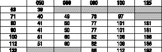
8 We i g h t s H Series SmartBox Weights (lbs) Weights are close approximations, rounded to the nearest pound. Weights do not include additional accessories. Weights include lubrication. 244


 S")


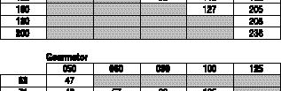


9 We i g h t s B Series SmartBox Weights (lbs) S Series SmartBox Weights (lbs) Weights are close approximations, rounded to the nearest pound. Weights do not include additional accessories. Weights include lubrication. 245
10 Installation and Use Recommendations for SmartBox installation: Avoid vibration by mounting the reducer securely to the application. Check the direction of rotation of the reducer output shaft before fitting the unit to the application. If the reducer is stored for long periods (4-6 months or more), make sure the oil seals are in contact with the reducer s internal lubricant. If the oil seal cannot contact the reducer s lubricant, change the oil seal before use. The seal s rubber coating may stick to the shaft or may lose the elasticity necessary to function properly. Mount hollow output shaft reducers with Motovario torque arms or output flanges. If Motovario mounts are not available, make sure the application allows for movement of the reducer. Whenever possible, protect the reducer against solar radiation and bad weather. Ensure the motor cools correctly by allowing air to flow freely on the motor s fan side. When ambient temperatures are below -5 C (23 F) or above 40 C (104 F), contact Motovario for assistance. Pulleys, sprockets, couplings, shafts and other output devices must be securely mounted on the solid or hollow shafts. Use threaded holes or similar locking methods to ensure correct operation without risking damage to the bearings or external reducer parts. Lubricate all surfaces in contact to avoid seizure or oxidation. Rubber parts (seals and o-rings) and the holes on the breather plugs (if applicable) must not be painted. Units equipped with oil plugs are shipped with closed plugs to prevent leaks during shipping. Replace the closed plug with the breather plug before use. Check for the correct level of the lubricant through the sight glass (if applicable). Do not immediately apply the maximum application load. Start-up slowly whenever possible. Take extra precautions when there are parts, objects, materials or people under the reducer that can be damaged by any oil leak. Applications operating in ambient temperatures below -30 C (-22 F) or over 60 C (140 F) require special oil seals. Applications operating in ambient temperatures under 0 C (32 F) have special needs: o Motors must be suitable for operation at the ambient temperature. o Colder temperatures require more starting torque from the motor. The motor power must be adequate to exceed the required starting torque. o Cast iron becomes fragile and brittle in temperatures under -15 C (5 F). The viscosity of the reducer lubrication is higher at start-up. Whenever possible, run the reducer under no load for a few minutes to decrease oil viscosity. Installations and maintenance guides are available from Motovario or at Motor Coupling Installation Motovario SmartBox reducers designed for c-face motors use a flexible motor coupling design to maximize start and stop shock load capacity. The Hytrel component of the coupling absorbs the shocks associated with harsh starts and stops. Motovario s motor coupling is designed to fit simply over the motor shaft for easy installation. When installing, make sure the motor shaft, pilot and flange are free of oil, dirt, paint or other contaminants. The motor key must fit securely to the motor shaft before installing the coupling. The coupling will fit against the motor shaft s shoulder, keeping the coupling securely in place. Fit the flexible coupling element to the motor coupling and position the motor and reducer together. Align the flexible component with the reducer component. Secure the motor to the reducer by bolting it to the input flange. Instruction sheets for IEC and NEMA motors are available from Motovario or at 246
11 Installation and Use Shaft Construction Motovario customers can mount the SmartBox B and S series directly on to the drive shaft of their application. The drive shaft must be manufactured according to the dimensions shown in the following diagrams. Not following these dimensions can lead to shaft deformation, inability to service or remove the reducer from the application or cancellation of the factory warranty. The suggested length of the drive shaft from the shoulder to shaft-end is dimension V. The shaft length must be greater than dimension VA on standard shaft units; greater than or equal to dimension V on shrink disk units. The drive shaft must be manufactured with a shoulder in order to mount the reducer securely. The reducer must be fixed to the application using a torque arm, output flange, mounting feet or by other means of stabilizing the reducer. If the reducer cannot be fixed, make sure the application allows for movement of the reducer assembly. Check the output rotation of the reducer before mounting to the application. Lubricate all metal surfaces that come in contact to avoid seizure and oxidation. Install the locking kit (retaining bolt, stainless steel washer and optional rubberized washer) to secure the drive shaft and reducer together. Use a rubberized or plastic washer inside the stainless steel washer to seal the hollow output bore from intrusion by water, dust or other contaminants. Do not over-tighten the retaining bolt so as to deform the washer. The locking kit will rotate with the drive shaft. Keep away loose items that may become tangled in the locking kit. Do not immediately apply the maximum load of an application. Start slowly whenever possible. 247


12 Installation and Use Shaft Construction B Shaft Dimensions S Shaft Dimensions 248
13 Installation and Use Shrink Disk Shaft Construction B Shrink Disk Shaft Dimensions S Shrink Disk Shaft Dimensions 249
14 N o t e s 250
15 Terms and Conditions of Sale Wa r r a n t y The following will be the standard terms and conditions of sale between Motovario Corporation (noted herein as Motovario ) and its customers. Solely Motovario terms and conditions of sale will determine Motovario s liabilities. It is understood that upon acceptance by Motovario of a customer s purchase order, the terms and conditions noted herein shall govern. No modification of, or addition to, the terms and conditions of sale outlined herein will be recognized by Motovario unless specifically agreed to in writing and signed by an officer of Motovario Corporation. All prices are F.O.B. Alpharetta, GA. Method of pre-paid shipment is at the sole discretion of Motovario. Weights are carefully estimated, but not guaranteed. Payment Terms Unless otherwise provided, terms of payment are 30 days net from the date of invoice for customers with approved credit. Motovario reserves the right to charge interest up to the maximum rate allowed by law on any balance outstanding after the date payment is due. For those customers without approved credit, Motovario may require full or partial payment in advance to continue with the production or shipment of any open and/or pending o r d e r s. Motovario will not accept changes in the specification of an order unless such changes are requested in writing and agreed to in writing by an authorized officer of Motovario. Delivery Great care is taken in packaging Motovario s products, and Motovario cannot be held liable for breakage after having provided material in good working order to the transportation company. Motovario s responsibility ceases with the delivery to the carrier, at which time title passes to the consignee. At that time, all claims for loss, damage, and delay must be made to the carrier. Purchaser must make claims for shortages or incorrect material in writing within thirty (30) days after receipt of shipment; a failure to give Motovario such written notice within said thirty (30) day period shall serve as an unqualified acceptance of the products provided, and a waiver by the purchaser of all such claims. When goods are received in a damaged condition with the container intact, the consignee should obtain a concealed damage report from the carrier on the day of delivery. Cancellation or Suspension Orders placed with Motovario are not subject to cancellation or suspension except with Motovario s consent and upon payment to Motovario of cancellation charges. Limited Warranty Motovario warrants all of its products against defects in material and workmanship for a period of one (1) year in service to a maximum of 18 months from the date of shipment. Motovario s obligation under this warranty is to service, repair, or replace any unit returned to Motovario for that specific purpose with transportation charges prepaid. Any attempt to repair Motovario products by anyone other than Motovario voids this warranty. Use of products above rated capacity, misuse, field alterations of products, damage due to lack of maintenance or improper storage, neglect or accident are also excluded from this Limited Warranty. Any equipment or components of the products supplied that are not of Motovario s own manufacture are sold under such warranty as the maker thereof provides Motovario and Motovario is able to enforce: Such items are not warranted by Motovario in any way. Returned Goods Policy Authorization and shipping instructions must be obtained by the purchaser from Motovario prior to returning any product. The product must be returned with complete identification in accordance with instructions provided by Motovario for the return to be accepted. In no event will Motovario be responsible for products returned without prior authorization or identification. Where the purchaser requests authorization to return to Motovario products for reasons other than an incorrect shipment by Motovario or damaged goods, a restocking charge of a minimum of 25% of the net invoiced amount for each item will be assessed for placing the returned goods in a salable condition and for outgoing freight paid by Motovario. Any product returned for repair that is outside the warranty coverage period noted above will be subject to labor and material costs. All labor and materials costs provided by Motovario and its employees are understood to be estimates only. Liability for Damage The liability of Motovario is strictly limited to the abovestated obligations. Motovario takes no responsibility deriving from accidents of any nature that may occur during use of the products sold, whether they be considered defective or otherwise; also in cases of the choice of application being recommended by personnel in the Motovario sales organization. The user is obligated, under his own exclusive responsibility, to proceed with the utmost caution and make provisions for safety devices that conform with applicable directives, standards and technical regulations, and to limit adequately damage to personnel and/or property that may result from failure. 251
16 N o t e s 252
C o n t e n t s. SmartBox Overview...2
 C o n t e n t s SmartBox Overview.......................2 Catalog Notes............................4 H Series SmartBox.....................7 Versions...............................8 Nomenclature.........................9
HSERIES. Helical geared motors
 HSERIES Helical geared motors Design features Motovario products are supplied with the following surface treatment features: Die-cast aluminium alloy cases for gears Die-cast materials undergo the following
Versions. f.s. Worm gear units CMRV CMRV-CMRV... PC-CMRV... CRV CRV-CMRV...
 Worm Gear Units 313 Versions CMRV 025-150 The service factor (f.s.) depends on the operating conditions the reduction unit is subjected to. The parameters that need to be taken into consideration to select
MAINTENANCE AND USE INSTRUCTIONS FOR WORM GEAR REDUCERS AND GEARMOTORS SERIES: SW - ISW - SW+SW ISW+SW
 MAINTENANCE AND USE INSTRUCTIONS FOR WORM GEAR REDUCERS AND GEARMOTORS SERIES: SW - ISW - SW+SW ISW+SW GB 2 Warehouse storage When moving the unit, care should be taken to protect external parts from breakage
NMRV - MCV - NRV NMRV+NMRV PC+NMRV
 MAINTENANCE AND OPERATING INSTRUCTIONS FOR WORM GEAR REDUCERS AND GEARMOTORS SERIES: NMRV - MCV - NRV NMRV+NMRV PC+NMRV GB NMRV-UM-9 99/01 rev.15.07.99 2 Warehouse storage When moving the unit, care should
PENBERTHY MODELS GL AND GH GAS OPERATED JET PUMPS INSTALLATION, OPERATION AND MAINTENANCE INSTRUCTIONS
 Before installation, these instructions must be read carefully and understood. PRODUCT WARRANTY Emerson warrants its Penberthy products as designed and manufactured to be free of defects in the material
STC E-Series Electrically Actuated Ball Valves 316 Stainless Steel, 2-Way or 3-Way
 STC E-Series Electrically Actuated Ball Valves 316 Stainless Steel, 2-Way or 3-Way Ordering Part No. = (e.g., E 1/2-3-S) Indicator / Control E 1/2 - - - 3-S Model Name Electric Actuated Valves E Port Size
ADI-125/750 ADI-125/1500 ADI-125/2500
 Manufacturer of Dimensions TM Inverters 4467 White Bear Parkway St. Paul, MN 55110 Phone: 651-653-7000 Fax: 651-653-7600 E-mail: inverterinfo@sensata.com Web: www.dimensions.sensata.com 121094B OWNERS
DeZURIK 2 20" BOS BUTTERFLY VALVES
 2 20" BOS BUTTERFLY VALVES Instruction D10459 October 2013 2-20 BOS Butterfly Valves Instructions These instructions provide information about BOS Butterfly Valves. They are for use by personnel who are
Raydot LLC 24 Actuator (115 VOLT)
") Installation, Operation & Parts Manual Read carefully the information provided. Retain manual for future reference. Raydot LLC 24 Actuator (115 VOLT) 145 Jackson Ave. S. Cokato, MN 55321-USA (320) 286-2103
Installation, Operation & Parts Manual Read carefully the information provided. Retain manual for future reference. Raydot LLC 24 Actuator (115 VOLT) 145 Jackson Ave. S. Cokato, MN 55321-USA (320) 286-2103
OWNERS MANUAL JANUARY 2007 ISO
 Manufacturer of Dimensions TM Inverters 4467 White Bear Parkway St. Paul, MN 55110 Phone: 651-653-7000 Fax: 651-653-7600 E-mail: inverterinfo@sensata.com Web: www.dimensions.sensata.com 121231B OWNERS
Installation and Maintenance Manual
 Installation and Maintenance Manual WorldWide Helical Inline Speed Reducers This operation manual includes important information for the installation, assembly, operation and maintenance of the WorldWide
LIGHTING RECREATIONAL VEHICLES ACCENT & COURTESY MARINE TRUCK & TRAILER RECREATIONAL VEHICLES INDUSTRIAL / COMMERCIAL
 LIGHTING RECREATIONAL VEHICLES ACCENT & COURTESY MARINE TRUCK & TRAILER RECREATIONAL VEHICLES INDUSTRIAL / COMMERCIAL WARRANTY INFORMATION LED (LIGHT EMITTING DIODE) LIMITED LIFETIME WARRANTY: Innovative
24 Linear Actuator 115 Volts A.C. (Cat. # C430A)
") Installation, Operation & Parts Manual Read carefully the information provided. Retain manual for future reference. 24 Linear Actuator 115 Volts A.C. (Cat. # C430A) Page 1 of 8 IS10007.doc 11/15/06 IMPORTANT!
Installation, Operation & Parts Manual Read carefully the information provided. Retain manual for future reference. 24 Linear Actuator 115 Volts A.C. (Cat. # C430A) Page 1 of 8 IS10007.doc 11/15/06 IMPORTANT!
TECHNICAL SERVICE MANUAL
 Electronic copies of the most current TSM issue can be found on the Viking Pump website at www.vikingpump.com TECHNICAL SERVICE MANUAL Viking In-Line Helical Gear Reducers Sizes 11, 21, 31, 35, 41, 51,
Gen 2 Clutch/Brake UniModule UM-50, UM-100, UM-180
 Gen 2 Clutch/Brake UniModule UM-50, UM-100, UM-180 P-273-4 819-0528 Installation Instructions Vented Enclosed Version Optional An Altra Industrial Motion Company Contents Mounting to a C-Face Motor........3
Effective June 1, 2013 This guide supersedes all previous versions
 Effective June 1, 2013 This guide supersedes all previous versions 3842 Redman Drive 1-800-797-7974 Fort Collins, CO 80524 www.commandlight.com L-CAS THANK YOU Please allow us to express a simple thank
TERMS OF USE TERMS AND CONDITIONS. Plumbing and Heating Products (PL-WR)
") TERMS OF USE 1. Watts pricing and product data is subject to change without notice and such changes supersede all previous versions. 2. Watts data is to be used as provided. Watts is not responsible for
TERMS OF USE 1. Watts pricing and product data is subject to change without notice and such changes supersede all previous versions. 2. Watts data is to be used as provided. Watts is not responsible for
S T C. STC Air Actuated Valves. Fine Quality. Precision Engineered Advanced Design. Excellent Prices. connects fluid power to industrial automation TM
 Precision Engineered Advanced Design Catalog No.: PUB09KS STC Air Actuated Valves Fine Quality Excellent Prices connects fluid power to industrial automation Website: StcValve.com STC PNEUMATIC ACTUATED
DC to AC Power Inverters
 Manufacturer of Dimensions TM Inverters 4467 White Bear Parkway St. Paul, MN 55110 Phone: 651-653-7000 Fax: 651-653-7600 E-mail: inverterinfo@sensata.com Web: www.dimensions.sensata.com ISO 9001:2000 Certified
3V SERIES SOLENOID VALVE
 3V110-410 SERIES SOLENOID VALVE Valve Model 3V110-1/8 3V210-1/4 3V310-3/8 3V410-1/2 Port & Mounting Action & Motion Operating Pressure Body Ported Air Pilot, Spool Design, Response Time
DC to AC Power Inverters
 Manufacturer of Dimensions TM Inverters 4467 White Bear Parkway St. Paul, MN 55110 Phone: 651-653-7000 Fax: 651-653-7600 E-mail: inverterinfo@sensata.com Web: www.dimensions.sensata.com 121114C OWNERS
24/3000H-3PH 24/4500H-3PH 24/6000H-3PH
 Manufacturer of Dimensions TM Inverters 4467 White Bear Parkway St. Paul, MN 55110 Phone: 651-653-7000 Fax: 651-653-7600 E-mail: inverterinfo@sensata.com Web: www.dimensions.sensata.com 120015D OWNERS
Installation Instructions
 85-3195 rev. 12 04-18 Installation Instructions Thank you for purchasing this antisway bar kit. Please read through these instructions before installation. Part #1139-117 Rear Anti-Sway Bar Kit 1½ diameter
Installation Instructions
 85-4209 rev. 05 11-18 Installation Instructions Thank you for purchasing this anti-sway bar kit. Please read through these instructions before installation. Factory Replacement Anti-Sway Bar Kit part #1129-135
Dimensions 12/800N 12/1200N D. DC to AC Power Inverters. OWNERS MANUAL for Models: OWNERS MANUAL April ISO 9001:2000 Certified Company
 Manufacturer of Dimensions Inverters 4467 White Bear Parkway St. Paul, MN 55110 Phone: 651-653-7000 Fax: 651-653-7600 E-mail: inverterinfo@sensata.com Web: www.dimensions.sensata.com OWNERS MANUAL April
LINTECH.
 Welcome to Our local technical support group consists of Automation Specialists located throughout the World. These Automation Specialists are experienced in the use of electronic and mechanical motion
Gen 2 Clutch/Brake UniModule UM-50, UM-100, UM-180
 Gen 2 Clutch/Brake UniModule UM-50, UM-100, UM-180 P-273-4-WE 819-0528 Service & Installation Instructions Vented Enclosed Version Optional An Altra Industrial Motion Company Contents Mounting to a C-Face
4V130P-430P SERIES AIR PILOT VALVE
 4V130P-430P SERIES AIR PILOT VALVE Valve Model 4V130P-1/8 4V230P-1/4 4V330P-3/8 4V430P-1/2 Port & Mounting Action & Motion Operating Pressure Body Ported Double Solenoid, Spool Design, 3 Position, Pressure
MIL-24/2600Q MIL-24/3200DQ
 Manufacturer of Dimensions TM Inverters 4467 White Bear Parkway St. Paul, MN 55110 Phone: 651-653-7000 Fax: 651-653-7600 E-mail: inverterinfo@sensata.com Web: www.dimensions.sensata.com 121473B OWNER'S
OWNERS MANUAL JANUARY 2007 ISO
 Manufacturer of Dimensions TM Inverters 4467 White Bear Parkway St. Paul, MN 55110 Phone: 651-653-7000 Fax: 651-653-7600 E-mail: inverterinfo@sensata.com Web: www.dimensions.sensata.com OWNERS MANUAL JANUARY
ATK LIMITED WARRANTY FOR REMANUFACTURED ENGINES
 ATK LIMITED WARRANTY FOR REMANUFACTURED ENGINES ATK and its subsidiaries distributes a broad range of new, recycled, remanufactured and truck replacement products through its company owned and operated
STC 2L Series Solenoid Valves
 STC 2L170-500 Series Solenoid Valves 2L170-500 Series Solenoid Valve Specifications Valve Model 2L170-3/8 2L170-1/2 2L170-3/4 2L200-1 2L300-1 1/2 2L500-2 Valve Type Action 2 Way, Normally Closed (NC) Pilot
SOLAR BOLT CHARGING SYSTEM INSTALLATION GUIDE
 CHARGING SYSTEM Doc 1.00 INST052 1 SOLAR BOLT CHARGING SYSTEM CONTENTS General Information... 2 Solar Panel Installation... 3 Solar Bolt Main Harness and Indicate Installation... 4 Cable Routing... 9 Solar
MULTIPOSITION AIR CYLINDER
 MULTIPOSITION AIR CYLINDER CAST ALUMINUM FOUR-POSITION - ALL AIR SERVICE INFORMATION MOUNTING! Devices should be mounted and positioned in such a manner that they cannot be accidentally operated. INSTALLATION
Owner s Manual GLASSLINED PUMP TANK
 Owner s Manual GLASSLINED PUMP TANK ANSI/NSF 61 Annex G Thank You for purchasing a pump tank. Properly installed and maintained, it should give you years of trouble free service. If you should decide that
Universal Bevel Drives Service Manual
 Engineering Service Bulletin #SB241202 Universal Bevel Drives Service Manual Cautions Following are some general cautions. All personnel shall use safe and sound practices and take all necessary precautionary
TONS. Before each shift: Before operating: Before initial operation of hoist:
 LEVER HOIST 0.25 9 TONS Manual Notice It is the responsibility of the owner/user to install, inspect, test, maintain, and operate these lever hoists in accordance with ASME B30.21, Safety Standard for
Installation Instructions and Warranty Information
 Installation Instructions and Warranty Information 1999 2003 Ford SuperDuty Truck and Excursion Part# 1669S, 1669S-1, 1669S-2 Read all instructions carefully before attempting installation. Rev. 10/05
Straight-Bore Clutch LSCC-32, 44, 54
 Straight-Bore Clutch LSCC-32, 44, 54 1 In accordance with Nexen s established policy of constant product improvement, the specifications contained in this manual are subject to change without notice. Technical
Air Curtain. Installation, Operating and Maintenance Instructions
 Installation, Operating and Maintenance Instructions Save this manual for future reference. Air Curtain Model Numbers: ES026, ES036, ES042, ES048, ES060, ES072 READ THIS OWNER S MANUAL CAREFULLY BEFORE
Terms and Conditions
 Terms and Conditions GUARANTEE: All Brighton-Best International, Inc. products are manufactured to rigid quality control standards which meet or exceed industry standards. Records and tests pertaining
SOLAR DASH CHARGING SYSTEM USER GUIDE
 SOLAR DASH CHARGING SYSTEM Doc 1.01 INST049 INSTALLATION STEP 1 Place 20 watt solar panel in the dash of the vehicle facing up. Note: For ideal results position the vehicle in a manner in which the solar
COMPRESSED AIR LOADER MODEL: AL-1
 COMPRESSED AIR LOADER MODEL: AL-1 Document: AL-1 IM 10-22-2011 TABLE OF CONTENTS Important Notices and Precautions 3 Quick Installation 4 Product Description 4 Principle of Operation 5 Unpacking and Inspection
INTERNATIONAL MALLEABLE IRON PIPE FITTINGS & UNIONS
 INTERNATIONAL MALLEABLE IRON PIPE FITTINGS & UNIONS PRICE SCHEDULE #101016 EFFECTIVE: OCTOBER 1, 2016 MADE IN BRAZIL, UNLESS NOTED 117 Gulick Street, Blossburg, PA 16912 www.wardmfg.com (800) 248-1027
DeZURIK AFR3 Filter Regulator Used on Pneumatic Cylinder Actuators
 AFR3 Filter Regulator Used on Pneumatic Cylinder Actuators Instructions D11033 August 2013 Instructions These instructions provide information about AFR3 Filter Regulators. They are for use by personnel
Stainless Steel Pilot Piston Solenoid Valve 2MS Series for High Temperature & High Pressure
 Stainless Steel Pilot Piston Solenoid Valve 2MS Series for High Temperature & High Pressure S T C TM To Order, Please Specify: 1) Model No., 2) Voltage 2 Way, NC Pilot Piston Stainless Steel Part No. Voltage
CUSTOM CARRIERS. Crane Carrier Company Standard Warranty
 CUSTOM CARRIERS Crane Carrier Company Standard Warranty CRANE CARRIER COMPANY ("Manufacturer") warrants each new Crane Carrier sold by it or any of its authorized distributors to be free from defects in
DeZURIK 2-24 (50-600mm) KGN-RSB BI-DIRECTIONAL CAST STAINLESS STEEL KNIFE GATE VALVES
 KGN-RSB BI-DIRECTIONAL CAST STAINLESS STEEL KNIFE GATE VALVES") 2-24 (50-600mm) KGN-RSB BI-DIRECTIONAL CAST STAINLESS STEEL KNIFE GATE VALVES Instruction D11023 October 2016 Instructions These instructions provide information about KGN-RSB Knife Gate Valves. They are
2-24 (50-600mm) KGN-RSB BI-DIRECTIONAL CAST STAINLESS STEEL KNIFE GATE VALVES Instruction D11023 October 2016 Instructions These instructions provide information about KGN-RSB Knife Gate Valves. They are
Installation Instructions
 85-3909 rev. 01 09-09 Installation Instructions Thank you for purchasing this anti-sway bar kit. Please read through these instructions before installation. Rear Anti-Sway Bar Kit for Chevrolet G30 part
ENTERTAINMENT. BGV-D8+ Supplement to Manual # Tonne to 1.3 Tonne 250 kg to 1300 kg (REV. AA) E627NH
 E627NH") ENTERTAINMENT BGV-D8+ Supplement to Manual #00000999.25 Tonne to 1.3 Tonne 250 kg to 1300 kg Columbus McKinnon Corporation CM Entertainment 140 John James Audubon Parkway Amherst, New York 14228-1197 1-800-888-0985
ENTERTAINMENT BGV-D8+ Supplement to Manual #00000999.25 Tonne to 1.3 Tonne 250 kg to 1300 kg Columbus McKinnon Corporation CM Entertainment 140 John James Audubon Parkway Amherst, New York 14228-1197 1-800-888-0985
LKQ LIMITED WARRANTY FOR REMANUFACTURED ENGINES
 LKQ LIMITED WARRANTY FOR REMANUFACTURED ENGINES LKQ Corporation and its subsidiaries distributes a broad range of new, recycled, remanufactured and reconditioned automotive and truck replacement products
APCO CRF-100A RUBBER FLAPPER SWING CHECK VALVES
 APCO CRF-100A RUBBER FLAPPER SWING CHECK VALVES Instruction D12043 June 2016 DeZURIK Instructions These instructions provide installation, operation and maintenance information for APCO CRF-100A Rubber
StormPro BA Series Sump Pump
 Page 1 of 8 Marks & Meanings DANGER: Keep the pump equipment out of the reach of children! Warns that the failure to follow the directions given could cause serious risk to individuals or objects. WARNING:
STC 2DS Series Anti-Hammering Slow Closing Pilot Solenoid Valves
 STC 2DS500-2000 Series Anti-Hammering Slow Closing Pilot Solenoid Valves 2DS500-2000 Series Solenoid Valve Specifications Valve Model 2DS400F 2DS500F 2DS650F 2DS800F 2DS1000F 2DS1250F 2DS1500F 2DS2000F
DAP-625S and DAP-875S
 AIR CHAMP PRODUCTS DAP-625S and DAP-875S (i) FORM NO. L-20078-B-0501 In accordance with Nexen s established policy of constant product improvement, the specifications contained in this manual are subject
STC 2P025 Series Solenoid Valve
 STC 2P025 Series Solenoid Valve 2P025 Series Solenoid Valve Specifications Valve Model Valve Type Action Cv (Orifice) Operating Pressure Operating Temperature 2P025 2 Way, Normally Closed (NC) Direct Acting
2000HG NEW STYLE HELICAL GEAR RATIO MULTIPLIER. INSTALLATION AND MAINTENANCE MANUAL May 4, Indianapolis, Indiana (800)
") 2000HG NEW STYLE HELICAL GEAR RATIO MULTIPLIER INSTALLATION AND MAINTENANCE MANUAL May 4, 2017 Indianapolis, Indiana (800) 866-7973 e-mail: sales@sterlingelectric.com www.sterlingelectric.com 7997 Allison
2000HG NEW STYLE HELICAL GEAR RATIO MULTIPLIER INSTALLATION AND MAINTENANCE MANUAL May 4, 2017 Indianapolis, Indiana (800) 866-7973 e-mail: sales@sterlingelectric.com www.sterlingelectric.com 7997 Allison
Installation Instructions and Warranty Information
 Installation Instructions and Warranty Information For 2004-05 Nissan Titan 5.6L Part#1400S Read all instructions carefully before attempting installation. Rev. 10/05 Installation instructions for JBA
ATK Remanufactured Engine Warranty Revised 06/16
 Standard Warranty, NFWP, and NFWG programs are ONLY valid if the original installation was performed by a Licensed Automotive Repair Facility (LARF). NFWP and NFWG programs must be purchased at the time
Daily verifications : 1. Function and completeness of all operating and security equipment
 11921 Slauson Avenue. Santa Fe Springs, CA 90670 (800) 227-4116 General information You have decided to purchase a top Slidelift. The Maxon Slidelift is very easy to use and to maintain. It is equipped
NMRV SERIES WORM-GEAR SPEED REDUCERS
 NMRV SERIES WORMGEAR SPEED REDUCERS TRASMITAL GEAR INDIA PVT LTD Brief introduction to wormgear speed reducer Trasmital NMRV series wormgear speed reducer is a newgeneration product developed by our company
Installation, Operation, and Maintenance Manual
 Industrial Process Installation, Operation, and Maintenance Manual Series PBV Plastic Lined Ball Valve Table of Contents Table of Contents Introduction and Safety...2 Safety message levels...2 User health
The information in this instruction manual is subject to modifications without prior notice and is the exclusive property of Zorzini.
 Dear Customer, Thank you for choosing a Zorzini S.p.A. product. Zorzini manway doors and manhole covers 1 are designed and manufactured according to the highest standards in regards safety, functionality
Installation Instructions
 85-3511 rev. 04 11-15 Installation Instructions Polyurethane Bushing Kit for Ford F-53 (Front) (replaces OE bushings and brackets) part #4139-127 1-5/8 diameter INTRODUCTION Thank you for purchasing this
Badger Truck Refrigeration, Inc. Warranty Policy
 Badger Truck Refrigeration, Inc. Warranty Policy The manufacturer warrants each new heater, air conditioner or part to be free from defects in materials and workmanship under conditions of normal use and
Heavy Duty Four Wheeled Walker
 Heavy Duty Four Wheeled Walker Weight Capacity: 500 lbs. ITEM # W1802 Made in China 2011 ESSENTIAL MEDICAL SUPPLY, INC. Manufactured for Orlando, FL 32822 -- SAVE THESE INSTRUCTIONS -- Do not attempt to
GEARHEAD LIMITED WARRANTY FOR REMANUFACTURED ENGINES
 GEARHEAD LIMITED WARRANTY FOR REMANUFACTURED ENGINES GEARHEAD Engines distributes a broad range of new, recycled, remanufactured and reconditioned automotive and truck replacement products. Our remanufactured
Installation Instructions
 85-4592 rev. 08 02-18 Installation Instructions Thank you for purchasing our sway bar kit. Please read through these instructions before installation. Auxiliary Rear Anti-Sway Bar Kit for Ford F53 part
HV Gate Valve with pneumatic actuator
 HV Gate Valve with pneumatic actuator This manual is valid for the valve ordering number(s): 09134-_E14/24/34/44 09136-_E14/24/34/44 09138-_E14/24/34/44 09140-_E14/24/34/44 09144-_E14/24/34/44 The fabrication
INSTALLATION & OPERATION MANUAL
 INSTALLATION & OPERATION MANUAL VTC125d-6-12 Voltage Converter An ISO9001 and AS9100 Registered Company Battery Chargers Inverters Power Supplies Voltage Converters 8128 River Way, Delta B.C. V4G 1K5 Canada
Pneumatic Cylinder 14 Bore X 21 Stroke Part No. P Replaces Part No. P
 Pneumatic Cylinder 14 Bore X 21 Stroke Part No. P -322908-00000 Replaces Part No. P-191067-00000 Service Information WARNING: INSTALLATION AND MOUNTING The user of these devices must conform to all applicable
CO 3-WAY PNEUMATIC VALVE INSTRUCTION MANUAL 2080
 CO 3-WAY PNEUMATIC VALVE INSTRUCTION MANUAL 2080 STI S.r.l has taken every care in collecting and verifying the documentation contained in this Instruction Manual. The information herein contained are
Slidelift. Operator`s handbook GPS 44 X1 GPS 55 X1. Lift CORP Slauson Avenue. Santa Fe Springs, CA (800)
") Slidelift GPS 44 X1 GPS 55 X1 Lift CORP. 11921 Slauson Avenue. Santa Fe Springs, CA 90670 (800) 227-4116 Sörensen Hydraulik GmbH 28.03.2013 20 910 563 11921 Slauson Avenue. Santa Fe Springs, CA 90670
Slidelift GPS 44 X1 GPS 55 X1 Lift CORP. 11921 Slauson Avenue. Santa Fe Springs, CA 90670 (800) 227-4116 Sörensen Hydraulik GmbH 28.03.2013 20 910 563 11921 Slauson Avenue. Santa Fe Springs, CA 90670
DeZURIK KUL KNIFE GATE VALVES
 KUL KNIFE GATE VALVES Instruction D11025 September 2013 Instructions These instructions are intended for personnel who are responsible for the installation, operation and maintenance of your KUL knife
STāSIS Engineering R8 Brake System
 STāSIS Engineering R8 Brake System Brake Kit Installation Instruction Application Guide SE811-B30-91-00 R8 Brake System Special Tools Required Qty Description 1 10 MM Allen Head Socket 1 M10 Triple Square
Spare Parts, Instruction and Maintenance Manual for SPANCO Model 301 Jib Cranes
 Manual No. 103-0007 REV. 6/10 Spare Parts, Instruction and Maintenance Manual for SPANCO Model 301 Jib Cranes ISO 9001 REGISTERED SPANCO, Inc. 2 TABLE OF CONTENTS Forward... 4 Installation... 4-6 Maintenance...
EMISSION CONTROL WARRANTY STATEMENT
 EMISSION CONTROL WARRANTY STATEMENT YOUR WARRANTY RIGHTS AND OBLIGATIONS The California Air Resources Board, U.S. EPA and Zenith Power Products LLC (ZPP) are pleased to explain the emission control system
Installation Instructions and Warranty Information
 Installation Instructions and Warranty Information For JBA Headers 1997-2004 Chevrolet Corvette and z06 LS-1 / LS-6 V-8 Part# Application 1817 97-99 with 1-5/8 tube 1817-1 01-04 with 1-5/8 tube 1817-2
2V1-3V1 SERIES SOLENOID VALVE
 2V1-3V1 SERIES SOLENOID VALVE Valve Model 2V1 3V1 Port & Mounting Body Ported, Stacking Action & Motion Solenoid, Direct Acting, 2 Way Response Time
R E A D T H I S F I RST SAW USER GUIDE MODEL SVC4
 READ THIS FIRST SAW USER GUIDE MODEL SVC4 USER GUIDE This manual covers the description, cautions, operation, and maintenance of the Super Vac SV3. Please take the time to read this manual before operating
accidents which arise due to nonobservance and the safety information herein.
 2000LB WINCH Model: 7247 CALIFORNIA PROPOSITION 65 WARNING: You can create dust when you cut, sand, drill or grind materials such as wood, paint, metal, concrete, cement, or other masonry. This dust often
INSTALLATION INSTRUCTIONS
 REV 3 05/13/2016 INSTALLATION INSTRUCTIONS PART NO. 960001T 960003T PRODUCT DESCRIPTION: Full size Powered Light Bar Mid size Powered Light Bar Sport Bar and lights sold separately shown for reference
STC 2W Series Solenoid Valves
 STC 2W160-500 Series Solenoid Valves 2W160-500 Series Solenoid Valve Specifications Valve Model 2W160-3/8 2W160-1/2 2W200-3/4 2W250-1 2W350-1 1/4 2W400-1 1/2 2W500-2 Valve Type Action 2 Way, Normally Closed
Electromagnetic Particle Brakes Model: PRB-H
 P-223-3 819-0370 Electromagnetic Particle Brakes Model: PRB-H Installation Instructions Table of Contents Introduction............................2 Installation Instructions....................3 Start
APCO ASR-400/450 SEWAGE AIR RELEASE VALVES
 APCO ASR-400/450 SEWAGE AIR RELEASE VALVES Instruction D12005 December 2012 Instructions These instructions provide installation, operation and maintenance information for the APCO ASR- 400/450 Sewage
Rev. 10/27/2015 CDL-2000, MANUAL
 VESTIL MANUFACTURING CORP. 2999 North Wayne Street, P.O. Box 507, Angola, IN 46703 Telephone: (260) 665-7586 Toll Free (800) 348-0868 Fax: (260) 665-1339 www.vestilmfg.com e-mail: sales@vestil.com CDL-2000
WARRANTY POLICY. Grid-Tied Photovoltaic Inverters. Revision D. 2014, Solectria Renewables, LLC DOCIN
 WARRANTY POLICY Revision D 2014, Solectria Renewables, LLC DOCIN-070360 1 Product Warranty & RMA Policy 1. Warranty Policy Warranty Registration: It is important to have updated information about the inverter
Thermaltake Warranty / Support Information
 Thermaltake Warranty / Support Information Technical Support Thermaltake is committed to providing the highest quality, most reliable products for our valued customer. There are several ways you may contact
INSTALLATION INSTRUCTIONS
 REV 3 05/13/2016 INSTALLATION INSTRUCTIONS PART NO. 702001T PRODUCT DESCRIPTION: FRONT INNER FENDER LINER APPLICATION: JEEP WRANGLER / WRANGLER UNLIMITED PRODUCT SAFETY & LEGAL DISCLAIMER IMPORTANT READ
BSERIES. Helical bevel geared motors
 BSERIES Helical bevel geared motors FAX-BACK-FORM 01924 409 513 as required Geared Motors on Fast Delivery Company : Contact : Tel : Email : Inline Helical Enquiry Ref : Please complete or Bevel Helical
INSTALLATION INSTRUCTIONS
 REV 3 05/13/2016 INSTALLATION INSTRUCTIONS PART NO. 55311T / 55316T / 55321T 55326T / 55341T / 55346T PRODUCT DESCRIPTION: RC2 LR CENTRAL MOUNT RC2 LR BOTTOM MOUNT PRODUCT SAFETY & LEGAL DISCLAIMER IMPORTANT
NEW EQUIPMENT WARRANTY
 NEW EQUIPMENT WARRANTY We warrant that this equipment from U.S. Stoneware Corporation is within stated specifications and is free from defects in materials and workmanship. Our obligation under this warranty
Enclosed In-Line Helical & Right Angle Helical Gear Drives
 Enclosed In-Line Helical & Right Angle Helical Gear Drives P-3010-BG Doc. No. 65592 Installation and Operation 800B Series 800BR Series These instructions must be read thoroughly before installing or operating
Submersible Pump Model FA10.78Z with 4 Pole, 1740 RPM Motor and Two Vane Impeller
 Submersible Pump Model FA10.78Z with 4 Pole, 1740 RPM Motor and Two Vane Impeller Project Name: Project Manager: Chris Harnevious, Order Management Prepared By: Ray Herndon, Order Management FA 10.78Z,
GWC Valve International
 GWC Valve International PROVEN TECHNOLOGY FOR INDIVIDUAL VALVE SOLUTIONS WORLDWIDE API 6D SWING CHECK VALVES Pressure Class: ASME 150-2500 Size Range: 2-36 CATALOG NUMBER SC-1001 G W C V A L V E I N T
OWNER S MANUAL PRODUCT CODE: 2006T
 Jul-18 Product Code: 2006T OWNER S MANUAL PRODUCT CODE: 2006T HYDRAULIC PIPE BENDER 12,000KG Model Capacity Bending Die No of Attachments 12,000kg 1/2", 3/4", 1", 1-1/4", 1-1/2", 2" 6 Made in China to
Dual Phase Extraction Inlet. Patent No Installation Manual. P/N Rev
 Patent No. 6520259 Installation Manual P/N 95232 Rev 6-16-11 Table of Contents ing Extraction Inlets track changing water levels to maintain optimum performance 1.Component Identification Page 1 2. How
ST-70 CONTROL OPERATING MANUAL REVISION DATE: PART#:
 ST-70 CONTROL OPERATING MANUAL REVISION DATE: 05-15-07 PART#: 98-0002-09 SERVICE & CUSTOMER INFORMATION CUSTOMER MUST HAVE PART NUMBER WHEN ORDERING ITEMS THROUGH THE SERVICE DEPARTMENT. IF FURTHER HELP
Type Flexair Pneumatic Pressure Control Valves
 Industrial Hydraulics Electric Drives and Controls Linear Motion and Assembly Technologies Pneumatics Service Automation Mobile Hydraulics Type Flexair Pneumatic Pressure Control Valves Catalog pages from