C o n t e n t s. SmartBox Overview...2
|
|
|
- Aron Greer
- 5 years ago
- Views:
Transcription
1 C o n t e n t s SmartBox Overview Catalog Notes H Series SmartBox Versions Nomenclature Mounting Positions Motor Positions Reducer Positions Input Types Gear Reducer Ratings Input Speed 1750 RPM Input Speed 1140 RPM Input Speed 875 RPM Gearmotor Ratings, 1750 RPM H Series Dimensions Motor Mounting Dimensions B Series SmartBox Versions Nomenclature Mounting Positions Mounting Positions Terminal Box Positions Flange Positions Output Styles Direction of Rotation Input Types Gear Reducer Ratings Input Speed 1750 RPM Input Speed 1140 RPM Input Speed 875 RPM Gearmotor Ratings, 1750 RPM B Series Dimensions B Series Torque Arm B Series Shrink Disk Motor Mounting Dimensions S Series SmartBox Versions Nomenclature Mounting Positions Mounting Positions Flange Positions Terminal Box Positions Input Types Gear Reducer Ratings Input Speed 1750 RPM Input Speed 1140 RPM Input Speed 875 RPM Gearmotor Ratings, 1750 RPM S Series Dimensions S Series Torque Arm S Series Shrink Disk Motor Mounting Dimensions AC Motors AC Motor Features AC Motor Accessories AC Motor Connections Brake Motors AC Motor Ratings AC Motor Dimensions Engineering and Technical Specifications
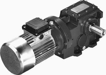
2 Motovario SmartBox was designed to be the most competitive high-efficiency gear reducer series in t o d a y s market. The key development factor of Motovario SmartBox is the Modularity Concept: modular production, modular assembly, modular gear reducers. SmartBox is built with standardized parts, sharing gears, shafts, input sets and output flanges to simplify the production process and improve delivery. T h e interchangeable parts make SmartBox gear reducers the most flexible reducer series available. SmartBox reducers can be easily adapted for any application. Motovario has developed a new, flexible, highperformance gear reducer series while improving production and performance quality. SmartBox introduces key design changes that reflect Motovario s commitment to innovation: The new flexible motor coupling design integrates the motor shaft and the reducer input quill to maximize start and stop shock load capacity. The Hytrel coupling eliminates fretting corrosion between the motor shaft and the input quill, making disassembly simple. The coupling design also increases the input oil seal s life by lowering temperature and reducing vibration at the input shaft. The compact coupling easily adapts for NEMA, IEC and servo motor applications. The SmartParts system is designed to standardize parts throughout the SmartBox series, lowering cost, shortening lead times and increasing application flexibility. High-speed helical gears are a common part in the SmartBox line, used in all three series (H,B and S). Low-speed helical gears are a shared part between the H and B series, while output shafts are common between the B and S series. All three series also share an interchangeable input set, including the input flanges, allowing parts to be preassembled for faster production and better quality. All SmartBox reducers feature the PowerCase onepiece castings of the main housing that enable the reducer to transmit more torque. The PowerCase also allows for more distance between support bearings, distributing loads more evenly and increasing overhung load ratings. The design of the PowerCase provides for a large inspection cover to help improve quality and simplify assembly and production. PowerCase uses the interchangeable input sets of the SmartParts system, so each reducer s power section can be tailored SmartBox Modularity Flexible Motor Coupling SmartParts Gear Sharing 2


3 for maximum torque. The design of the B series is focused on the weakest element of the reducer: the bevel gear. The load capacity of the reducer depends on the correct fitting and stability of the bevel gear and pinion. T h e SmartBox design solution is a bevel pinion supported between two bearings for more precise gear mesh and the elimination of gear deflection. The double-bearing design improves torque output and reducer shock-load capacity by removing the weakest link. SmartParts Input Flange Basic SmartBox Features Designed for continuous duty and use in harsh or stressful applications Gears and hollow output bores are carburized to a hardness of RC Load capacity calculated according to ISO 6336 and verified according to AGMA 2001-B88 High-strength housings and input and output flanges of gray cast-iron G200 Single stage reducers with efficiencies up to 98% (in-line helical H Series only) Double and triple stage reducers with efficiencies up to 95% Foot mount, flange mount, shaft mount, foot/flange mount and other configurations available SmartBox B Series bevel pinion support SmartBox H Series Power Case SmartBox B Series bevel pinion support (top view) 3
. More precise figures are available through Motovario.")
4 Catalog Notes Power, Torque and Speed Ratings and standard operating conditions are in reference to the reducer mounted in the standard horizontal position, B3 or similar, with the lubricant supplied by Motovario. Output torque ratings are rounded to the nearest integer. Ratios are rounded to the nearest hundredth (0.00). More precise figures are available through Motovario. Output speeds are rounded to the nearest integer. Speeds may vary slightly due to motor fluctuations or the application load applied. Ratings are in relation to the reducer s input speed. Dimensions SmartBox dimensions listed in this catalog are for standard reducers. Special applications and designs may change basic dimensions. Accessories and options are often listed as separate dimensions. Please refer to the specific accessories for dimensions. Output flanges are separate accessories and are referred to in Motovario nomenclature with the extension F or FA. Reducers may have more than one output flange option. In that case, the extension identifies an additional option (FB, FC, etc.). Dimensions of motors not supplied by Motovario may vary slightly. Please refer to the motor manufacturer for accurate dimensions and mounting configuration. Servo motors may require modified mounting configurations. Certified dimensions and 1:1 scale drawings in electronic formats are available through Motovario. Optional Design Features Backstop devices on motors Servo motor adapters Special paint or coatings for added protection Scoop motor mounts Special design output bores and shafts Please contact Motovario for your special design needs Surface Treatment Motovario products are supplied with the following surface treatments: Grey cast-iron reducer housings De-burring by mechanical shearing system Accurate shot-peening Painting Washing and passivation Die-cast materials are always painted. Paint used on Motovario reducers meets the following specifications: Orange-peel blue-colored epoxy-polyester RAL 5010 Polyester resin based heat-hardening powders, altered with epoxy resins, applied by electrostatic spray Heat resistance: 24 hours at 150 C (302 F) Corrosion strength: ASTM B 117/97 salt fog from 100 to 500 hours, depending on the surface s preliminary treatment Non-toxic and non-irritating according to EEC directives no. 67/548 (dangerous substances) and no. 88/379 (dangerous compounds) Tests carried out on degreased Unichim white lattens (film thickness: 60 microns) comply with the following s p e c i f i c a t i o n s : Adherence (ISO2409) Erichsen drawing (ISO152) Inverted shock (DIN53158) Cone-shaped mandrel (DIN53151) Hardness (ASTM D3363/74) Special Applications Motovario SmartBox reducers can be easily adapted for special environments. The reducer housings are rugged enough for most difficult applications without special preparation. Heavy Duty Reducers: No special preparation necessary for reducers. Motors: IP65 Enclosure Protection Added winding protection coat against moisture and humidity Added winding insulation Drain holes for moisture and condensation drainage Corrosion resistant hardware (standard) Blue RAL 5010 polyester-epoxy paint coating Metal terminal box cover Washdown and Food Application Reducers: Painted with white epoxy paint or stainless-steel type paint Food-grade lubricant available Spring-loaded valve breather plugs Stainless-steel hollow output bore and output shafts BISSC approval of gear reducer models Washdown Motors: IP65 Enclosure Protection Painted with white epoxy paint or stainless-steel type paint Metal terminal box cover Harsh Environment Reducers: Low- or high-temperature lubricant Viton high-temperature resistant seals Extreme low-temperature seals Harsh Environment Motors: IP65 Enclosure Protection Added winding protection coat against moisture and humidity Added winding insulation Drain holes for moisture and condensation drainage Winding heaters for extremely low temperature applications Forced ventilation blower for high temperature or inverter drive applications Corrosion resistant hardware (standard) Blue RAL 5010 polyester-epoxy paint coating Metal terminal box cover 4
5 D e s c r i p t i o n s H Series Cast Iron Housings NEMA or IEC input coupling Inch or metric dimension input and output S Series Cast Iron Housings NEMA or IEC input coupling Inch or metric dimension input and output CH PH IH Fx M Hxx1 Hxx2 Hxx3 O p t i o n s In-line helical gearmotor In-line helical gear reducer with input coupling In-line helical gear reducer with input shaft Output flange for in-line helical reducer Mono version, output offset down In-line helical reducer, single stage In-line helical reducer, double stage In-line helical reducer, triple stage Heavy Duty Washdown Specific Harsh Environments CS PS IH C Fx D L Options Parallel shaft mount gearmotor Parallel shaft mount gear reducer with input coupling Parallel shaft mount gear reducer with input shaft Hollow output bore for shaft mount Output flange for parallel shaft mount reducer Single extension output shaft for parallel shaft mount reducer Shrink disk mounting for parallel shaft mount reducer Heavy Duty Washdown Specific Harsh Environments Torque arm Shaft-lock system for shaft mount applications B Series Cast Iron Housings NEMA or IEC input coupling Inch or metric dimension input and output Triple stage reduction CB PH IH Helical bevel gearmotor Helical bevel gear reducer with input coupling Helical bevel gear reducer with input shaft U Universal mounting capability; surfaces for foot or flange mounting C Hollow output bore for shaft mount Fx Output flange for helical bevel reducer S, D Single extension output shaft for helical bevel reducer, left or right extension P Double extension output shaft for helical bevel reducer L, M Shrink disk mounting for helical bevel reducer, left or right mounting AC Motors IEC frame, squirrel-cage motors Finned, aluminum housings through IEC 132 frame IP55 Class F insulation TEFC 50Hz or 60Hz frequency 230/460V T TB Three phase AC motor Three phase AC brakemotor Frame size of Motovario Aluminum housing AC Motors, 1/6HP to 10HP Frame size of high power AC motors, 15HP to 60HP B11 B14 B5 Integral motor for gearmotors Face-mounted output Flange mounted output Options Heavy Duty Washdown Specific Harsh Environments Torque arm Shaft-lock system for shaft mount applications Options Two, four, six or eight poles TENV Heavy Duty Washdown Specific Harsh Environments 5
6 6 N o t e s


7 Helical Geared Motors and Helical Geared Units H CH PH IH 7


8 H Ve r s i o n s Single Stage Foot Mount Single Stage Flange Mount 041F- 051F- 061F- 081F-101F-121F Single Stage Mono Style Output Offset Down 041M - 051M - 061M - 081M -101M -121M Double/Triple Stage Foot Mount Double/Triple Stage Flange Mount 032F- 042F- 052F- 062F- 082F-102F 122F-142F 033F- 043F- 053F- 063F- 083F-103F 123F-143F 8
9 Nomenclature H CH 082 FB T 90S4 Pos2 50mm B Style CH In-line Helical Gearmotor Motovario three-phase integral motor is permanently attached to the reducer. The motor and the reducer are supplied together. PH In-line Helical Gear Reducer with Input Coupling C-face-type input flange allows the reducer to accept standard NEMA and IEC motors with C-face adapters. The motor shaft is coupled to the reducer using a twopiece coupling. Motors are supplied separately from the gear reducers. IH In-line Helical Gear Reducer with Input Shaft Inchstandard or metric dimensioned input shaft allows for standard sprocket or pulley attachment, direct motor coupling or other types of free input. 2. Size One Stage Gear Reduction Two Stage Reduction Three Stage Reduction Output Style M/Mono Version Single stage in-line helical reducer outputs are offset from the input; offset up is standard. The Mono version offsets the output down for lower output shaft height in certain applications. FA, FB, FC/Output Flange In-line helical units have different output flange choices, depending on the size of the gear reducer. In-line units with output mounting flanges are a different body style than the standard foot mounted units. Please refer to the dimensional drawings for details. 4. Reduction Ratio The reduction ratio determines the output speed of the r e d u c e r. Ratios will vary depending on the size of the r e d u c e r. For a list of reduction ratios, please refer to pages or Input Type T Three Phase Integral Motor CH units are supplied with Motovario three-phase motors. Please check motor size compatibility on pages P IEC Input Coupling PH units supplied with IEC standard motor inputs must specify the frame size of the mounted motor. SmartBox units are only available with the B5 style IEC input flange. Please check input flange availability on pages N NEMA Input Coupling PH units supplied with NEMA standard C-face motor inputs must specify the frame size of the mounted motor. Please check input flange availability on pages UB Input Shaft Please specify the diameter of the input shaft in inches or millimeters. Input shaft sizes are specified on the gear reducer dimension pages, Integral Motor Description of Motor Frame Size, Power and Speed The motor frame size, power and speed must be specified when ordering a CH style SmartBox. Please check the gearmotor ratings on pages for gearmotor specifications. or Input Coupling Frame Size The motor frame size, either IEC or NEMA, must be specified when ordering a PH style SmartBox. Please check with the motor supplier for the correct frame size. 7. Motor Mounting Position Integral Motors The motor mounting position is specified only when ordering the SmartBox CH style units. The motor mounting position indicates the position of the terminal box and the wire strain relief connection. The motor mounting position always refers to the gear reducer in position B3. Please refer to page 10 for motor mounting position specifications. 8. Output Shaft Diameter Specify the diameter of the output shaft in inches or millimeters. Output shaft sizes are specified on the gear reducer dimension pages, Reducer Mounting Position The mounting position of the gear reducer or gearmotor must be specified when ordering for the proper placement of the sight glass and lubrication amount. Please refer to page 11 for mounting positions. 9
10 H Series Features Motovario SmartBox H Series takes full advantage of the SmartParts concept, using standardized parts, shared gears, shafts, input sets and output flanges. Key design features of the SmartBox H Series include: New flexible motor coupling design SmartParts standardized parts One-piece PowerCase cast-iron housings Wider distance between support bearings Maximum performance in harsh or stressful applications Hardened gears Efficiencies up to 98% in single-stage reducers Efficiencies up to 95% in double and triple stage reducers Foot or flange mount H Terminal Box Positions Mounting position must be specified when ordering to provide the proper gear configuration and lubrication quantity. If mounting position is not specified, gear reducers are supplied in position B3/B5 (standard position). The motor terminal box position must be specified, according to the diagram, when ordering gearmotors. If terminal box position is not specified, the gearmotor is supplied with the terminal box in position 1. Terminal box positions always relate to the gear reducer mounted in position B3/B5. For vertical mounting positions, refer to the Engineering and Technical Specifications section of this catalog. For positions not specified in this catalog, please contact Motovario. 10
11 Mounting Positions H 11


12 H Input Ty p e s CH- PH 032 CH- PH 033 CH- PH 041 NEMA reducers available with c-face input only. B5: Indicates IEC motor mount is available. B11: Indicates integral IEC motor is available. 12

13 Input Types H CH- PH 042 CH- PH 043 CH- PH 051 NEMA reducers available with c-face input only. B5: Indicates IEC motor mount is available. B11: Indicates integral IEC motor is available. 13


14 H Input Ty p e s CH- PH 052 CH- PH 053 CH- PH 061 NEMA reducers available with c-face input only. B5: Indicates IEC motor mount is available. B11: Indicates integral IEC motor is available. 14


15 Input Types H CH- PH 062 CH- PH 063 CH- PH 081 NEMA reducers available with c-face input only. B5: Indicates IEC motor mount is available. B11: Indicates integral IEC motor is available. 15


16 H Input Ty p e s CH- PH 082 CH- PH 083 CH- PH 101 NEMA reducers available with c-face input only. B5: Indicates IEC motor mount is available. B11: Indicates integral IEC motor is available. 16


17 Input Types H CH- PH 102 CH- PH 103 NEMA reducers available with c-face input only. B5: Indicates IEC motor mount is available. B11: Indicates integral IEC motor is available. 17


18 H Input Ty p e s CH- PH 121 CH- PH 122 CH- PH 123 NEMA reducers available with c-face input only. B5: Indicates IEC motor mount is available. B11: Indicates integral IEC motor is available. 18


19 Input Types H PH 142 PH 143 NEMA reducers available with c-face input only. B5: Indicates IEC motor mount is available. B11: Indicates integral IEC motor is available. 19
20 H Gear Reducer Ratings Input Speed 1750 RPM Maximum Torque in lbs Output Speed RPM Exact Ratio i Maximum Power HP OHL Output Shaft Input Shaft Gear Reducer Motorized Input Shaft Input PH032 IH PH032 IH PH032 IH PH032 IH PH032 IH PH032 IH PH032 IH PH032 IH PH032 IH PH032 IH PH032 IH PH032 IH PH032 IH PH032 IH PH032 IH PH032 IH PH032 IH PH032 IH PH032 IH PH033 IH PH033 IH PH033 IH PH033 IH PH033 IH PH033 IH PH033 IH PH033 IH PH033 IH PH033 IH PH041 IH PH041 IH PH041 IH PH041 IH PH041 IH PH041 IH PH041 IH PH041 IH PH041 IH PH041 IH PH041 IH PH041 IH041 20
21 Gear Reducer Ratings Input Speed 1750 RPM H Maximum Torque in lbs Output Speed RPM Exact Ratio i Maximum Power HP OHL Output Shaft Input Shaft Gear Reducer Motorized Input Shaft Input PH042 IH PH042 IH PH042 IH PH042 IH PH042 IH PH042 IH PH042 IH PH042 IH PH042 IH PH042 IH PH042 IH PH042 IH PH042 IH PH042 IH PH042 IH PH042 IH PH042 IH PH042 IH PH043 IH PH043 IH PH043 IH PH043 IH PH043 IH PH043 IH PH043 IH PH043 IH PH043 IH PH043 IH PH051 IH PH051 IH PH051 IH PH051 IH PH051 IH PH051 IH PH051 IH PH051 IH PH051 IH PH051 IH PH051 IH PH051 IH051 21
22 H Gear Reducer Ratings Input Speed 1750 RPM Maximum Torque in lbs Output Speed RPM Exact Ratio i Maximum Power HP OHL Output Shaft Input Shaft Gear Reducer Motorized Input Shaft Input PH052 IH PH052 IH PH052 IH PH052 IH PH052 IH PH052 IH PH052 IH PH052 IH PH052 IH PH052 IH PH052 IH PH052 IH PH052 IH PH052 IH PH052 IH PH052 IH PH052 IH PH052 IH PH052 IH PH053 IH PH053 IH PH053 IH PH053 IH PH053 IH PH053 IH PH053 IH PH053 IH PH053 IH PH061 IH PH061 IH PH061 IH PH061 IH PH061 IH PH061 IH PH061 IH PH061 IH PH061 IH PH061 IH PH061 IH061 22
23 Gear Reducer Ratings Input Speed 1750 RPM H Maximum Torque in lbs Output Speed RPM Exact Ratio i Maximum Power HP OHL Output Shaft Input Shaft Gear Reducer Motorized Input Shaft Input PH062 IH PH062 IH PH062 IH PH062 IH PH062 IH PH062 IH PH062 IH PH062 IH PH062 IH PH062 IH PH062 IH PH062 IH PH062 IH PH062 IH PH062 IH PH062 IH PH062 IH PH062 IH PH063 IH PH063 IH PH063 IH PH063 IH PH063 IH PH063 IH PH063 IH PH063 IH PH063 IH PH063 IH PH063 IH PH063 IH PH063 IH PH081 IH PH081 IH PH081 IH PH081 IH PH081 IH PH081 IH PH081 IH PH081 IH PH081 IH PH081 IH PH081 IH PH081 IH081 23
24 H Gear Reducer Ratings Input Speed 1750 RPM Maximum Torque in lbs Output Speed RPM Exact Ratio i Maximum Power HP OHL Output Shaft Input Shaft Gear Reducer Motorized Input Shaft Input PH082 IH PH082 IH PH082 IH PH082 IH PH082 IH PH082 IH PH082 IH PH082 IH PH082 IH PH082 IH PH082 IH PH082 IH PH082 IH PH082 IH PH082 IH PH082 IH PH082 IH PH082 IH PH082 IH PH082 IH PH083 IH PH083 IH PH083 IH PH083 IH PH083 IH PH083 IH PH083 IH PH083 IH PH083 IH PH083 IH PH083 IH PH083 IH PH083 IH PH101 IH PH101 IH PH101 IH PH101 IH PH101 IH PH101 IH PH101 IH PH101 IH PH101 IH PH101 IH PH101 IH PH101 IH101 24
25 Gear Reducer Ratings Input Speed 1750 RPM H Maximum Torque in lbs Output Speed RPM Exact Ratio i Maximum Power HP OHL Output Shaft Input Shaft Gear Reducer Motorized Input Shaft Input PH102 IH PH102 IH PH102 IH PH102 IH PH102 IH PH102 IH PH102 IH PH102 IH PH102 IH PH102 IH PH102 IH PH102 IH PH102 IH PH102 IH PH102 IH PH102 IH PH102 IH PH102 IH PH102 IH PH102 IH PH103 IH PH103 IH PH103 IH PH103 IH PH103 IH PH103 IH PH103 IH PH103 IH PH103 IH PH103 IH PH103 IH PH103 IH PH103 IH PH103 IH PH121 IH PH121 IH PH121 IH PH121 IH PH121 IH PH121 IH PH121 IH PH121 IH PH121 IH PH121 IH PH121 IH PH121 IH PH121 IH121 25
26 H Gear Reducer Ratings Input Speed 1750 RPM Maximum Torque in lbs Output Speed RPM Exact Ratio i Maximum Power HP OHL Output Shaft Input Shaft Gear Reducer Motorized Input Shaft Input PH122 IH PH122 IH PH122 IH PH122 IH PH122 IH PH122 IH PH122 IH PH122 IH PH122 IH PH122 IH PH122 IH PH122 IH PH122 IH PH122 IH PH122 IH PH122 IH PH122 IH PH122 IH PH123 IH PH123 IH PH123 IH PH123 IH PH123 IH PH123 IH PH123 IH PH123 IH PH123 IH PH123 IH PH123 IH PH123 IH PH123 IH PH123 IH PH123 IH PH123 IH123 26
27 Gear Reducer Ratings Input Speed 1750 RPM H Maximum Torque in lbs Output Speed RPM Exact Ratio i Maximum Power HP OHL Output Shaft Input Shaft Gear Reducer Motorized Input Shaft Input PH142 IH PH142 IH PH142 IH PH142 IH PH142 IH PH142 IH PH142 IH PH142 IH PH142 IH PH142 IH PH142 IH PH142 IH PH142 IH PH142 IH PH142 IH PH143 IH PH143 IH PH143 IH PH143 IH PH143 IH PH143 IH PH143 IH PH143 IH PH143 IH PH143 IH PH143 IH PH143 IH PH143 IH PH143 IH PH143 IH143 27
28 H Gear Reducer Ratings Input Speed 1140 RPM Maximum Torque in lbs Output Speed RPM Exact Ratio i Maximum Power HP OHL Output Shaft Input Shaft Gear Reducer Motorized Input Shaft Input PH032 IH PH032 IH PH032 IH PH032 IH PH032 IH PH032 IH PH032 IH PH032 IH PH032 IH PH032 IH PH032 IH PH032 IH PH032 IH PH032 IH PH032 IH PH032 IH PH032 IH PH032 IH PH032 IH PH033 IH PH033 IH PH033 IH PH033 IH PH033 IH PH033 IH PH033 IH PH033 IH PH033 IH PH033 IH H041 IH H041 IH H041 IH H041 IH H041 IH H041 IH H041 IH H041 IH H041 IH H041 IH H041 IH H041 IH041 28
29 Gear Reducer Ratings Input Speed 1140 RPM H Maximum Torque in lbs Output Speed RPM Exact Ratio i Maximum Power HP OHL Output Shaft Input Shaft Gear Reducer Motorized Input Shaft Input PH042 IH PH042 IH PH042 IH PH042 IH PH042 IH PH042 IH PH042 IH PH042 IH PH042 IH PH042 IH PH042 IH PH042 IH PH042 IH PH042 IH PH042 IH PH042 IH PH042 IH PH042 IH PH043 IH PH043 IH PH043 IH PH043 IH PH043 IH PH043 IH PH043 IH PH043 IH PH043 IH PH043 IH H051 IH H051 IH H051 IH H051 IH H051 IH H051 IH H051 IH H051 IH H051 IH H051 IH H051 IH H051 IH051 29
30 H Gear Reducer Ratings Input Speed 1140 RPM Maximum Torque in lbs Output Speed RPM Exact Ratio i Maximum Power HP OHL Output Shaft Input Shaft Gear Reducer Motorized Input Shaft Input PH052 IH PH052 IH PH052 IH PH052 IH PH052 IH PH052 IH PH052 IH PH052 IH PH052 IH PH052 IH PH052 IH PH052 IH PH052 IH PH052 IH PH052 IH PH052 IH PH052 IH PH052 IH PH052 IH PH053 IH PH053 IH PH053 IH PH053 IH PH053 IH PH053 IH PH053 IH PH053 IH PH053 IH H061 IH H061 IH H061 IH H061 IH H061 IH H061 IH H061 IH H061 IH H061 IH H061 IH H061 IH061 30
31 Gear Reducer Ratings Input Speed 1140 RPM H Maximum Torque in lbs Output Speed RPM Exact Ratio i Maximum Power HP OHL Output Shaft Input Shaft Gear Reducer Motorized Input Shaft Input PH062 IH PH062 IH PH062 IH PH062 IH PH062 IH PH062 IH PH062 IH PH062 IH PH062 IH PH062 IH PH062 IH PH062 IH PH062 IH PH062 IH PH062 IH PH062 IH PH062 IH PH062 IH PH063 IH PH063 IH PH063 IH PH063 IH PH063 IH PH063 IH PH063 IH PH063 IH PH063 IH PH063 IH PH063 IH PH063 IH PH063 IH H081 IH H081 IH H081 IH H081 IH H081 IH H081 IH H081 IH H081 IH H081 IH H081 IH H081 IH H081 IH081 31
32 H Gear Reducer Ratings Input Speed 1140 RPM Maximum Torque in lbs Output Speed RPM Exact Ratio i Maximum Power HP OHL Output Shaft Input Shaft Gear Reducer Motorized Input Shaft Input PH082 IH PH082 IH PH082 IH PH082 IH PH082 IH PH082 IH PH082 IH PH082 IH PH082 IH PH082 IH PH082 IH PH082 IH PH082 IH PH082 IH PH082 IH PH082 IH PH082 IH PH082 IH PH082 IH PH082 IH PH083 IH PH083 IH PH083 IH PH083 IH PH083 IH PH083 IH PH083 IH PH083 IH PH083 IH PH083 IH PH083 IH PH083 IH PH083 IH H101 IH H101 IH H101 IH H101 IH H101 IH H101 IH H101 IH H101 IH H101 IH H101 IH H101 IH H101 IH101 32
33 Gear Reducer Ratings Input Speed 1140 RPM H Maximum Torque in lbs Output Speed RPM Exact Ratio i Maximum Power HP OHL Output Shaft Input Shaft Gear Reducer Motorized Input Shaft Input PH102 IH PH102 IH PH102 IH PH102 IH PH102 IH PH102 IH PH102 IH PH102 IH PH102 IH PH102 IH PH102 IH PH102 IH PH102 IH PH102 IH PH102 IH PH102 IH PH102 IH PH102 IH PH102 IH PH102 IH PH103 IH PH103 IH PH103 IH PH103 IH PH103 IH PH103 IH PH103 IH PH103 IH PH103 IH PH103 IH PH103 IH PH103 IH PH103 IH PH103 IH H121 IH H121 IH H121 IH H121 IH H121 IH H121 IH H121 IH H121 IH H121 IH H121 IH H121 IH H121 IH H121 IH121 33
34 H Gear Reducer Ratings Input Speed 1140 RPM Maximum Torque in lbs Output Speed RPM Exact Ratio i Maximum Power HP OHL Output Shaft Input Shaft Gear Reducer Motorized Input Shaft Input PH122 IH PH122 IH PH122 IH PH122 IH PH122 IH PH122 IH PH122 IH PH122 IH PH122 IH PH122 IH PH122 IH PH122 IH PH122 IH PH122 IH PH122 IH PH122 IH PH122 IH PH122 IH PH123 IH PH123 IH PH123 IH PH123 IH PH123 IH PH123 IH PH123 IH PH123 IH PH123 IH PH123 IH PH123 IH PH123 IH PH123 IH PH123 IH PH123 IH PH123 IH123 34
35 Gear Reducer Ratings Input Speed 1140 RPM H Maximum Torque in lbs Output Speed RPM Exact Ratio i Maximum Power HP OHL Output Shaft Input Shaft Gear Reducer Motorized Input Shaft Input PH142 IH PH142 IH PH142 IH PH142 IH PH142 IH PH142 IH PH142 IH PH142 IH PH142 IH PH142 IH PH142 IH PH142 IH PH142 IH PH142 IH PH142 IH PH143 IH PH143 IH PH143 IH PH143 IH PH143 IH PH143 IH PH143 IH PH143 IH PH143 IH PH143 IH PH143 IH PH143 IH PH143 IH PH143 IH PH143 IH143 35
36 H Gear Reducer Ratings Input Speed 875 RPM Maximum Torque in lbs Output Speed RPM Exact Ratio i Maximum Power HP OHL Output Shaft Input Shaft Gear Reducer Motorized Input Shaft Input PH032 IH PH032 IH PH032 IH PH032 IH PH032 IH PH032 IH PH032 IH PH032 IH PH032 IH PH032 IH PH032 IH PH032 IH PH032 IH PH032 IH PH032 IH PH032 IH PH032 IH PH032 IH PH032 IH PH033 IH PH033 IH PH033 IH PH033 IH PH033 IH PH033 IH PH033 IH PH033 IH PH033 IH PH033 IH PH041 IH PH041 IH PH041 IH PH041 IH PH041 IH PH041 IH PH041 IH PH041 IH PH041 IH PH041 IH PH041 IH PH041 IH041 36
37 Gear Reducer Ratings Input Speed 875 RPM H Maximum Torque in lbs Output Speed RPM Exact Ratio i Maximum Power HP OHL Output Shaft Input Shaft Gear Reducer Motorized Input Shaft Input PH042 IH PH042 IH PH042 IH PH042 IH PH042 IH PH042 IH PH042 IH PH042 IH PH042 IH PH042 IH PH042 IH PH042 IH PH042 IH PH042 IH PH042 IH PH042 IH PH042 IH PH042 IH PH043 IH PH043 IH PH043 IH PH043 IH PH043 IH PH043 IH PH043 IH PH043 IH PH043 IH PH043 IH PH051 IH PH051 IH PH051 IH PH051 IH PH051 IH PH051 IH PH051 IH PH051 IH PH051 IH PH051 IH PH051 IH PH051 IH051 37
38 H Gear Reducer Ratings Input Speed 875 RPM Maximum Torque in lbs Output Speed RPM Exact Ratio i Maximum Power HP OHL Output Shaft Input Shaft Gear Reducer Motorized Input Shaft Input PH052 IH PH052 IH PH052 IH PH052 IH PH052 IH PH052 IH PH052 IH PH052 IH PH052 IH PH052 IH PH052 IH PH052 IH PH052 IH PH052 IH PH052 IH PH052 IH PH052 IH PH052 IH PH052 IH PH053 IH PH053 IH PH053 IH PH053 IH PH053 IH PH053 IH PH053 IH PH053 IH PH053 IH PH061 IH PH061 IH PH061 IH PH061 IH PH061 IH PH061 IH PH061 IH PH061 IH PH061 IH PH061 IH PH061 IH061 38
39 Gear Reducer Ratings Input Speed 875 RPM H Maximum Torque in lbs Output Speed RPM Exact Ratio i Maximum Power HP OHL Output Shaft Input Shaft Gear Reducer Motorized Input Shaft Input PH062 IH PH062 IH PH062 IH PH062 IH PH062 IH PH062 IH PH062 IH PH062 IH PH062 IH PH062 IH PH062 IH PH062 IH PH062 IH PH062 IH PH062 IH PH062 IH PH062 IH PH062 IH PH063 IH PH063 IH PH063 IH PH063 IH PH063 IH PH063 IH PH063 IH PH063 IH PH063 IH PH063 IH PH063 IH PH063 IH PH063 IH PH081 IH PH081 IH PH081 IH PH081 IH PH081 IH PH081 IH PH081 IH PH081 IH PH081 IH PH081 IH PH081 IH PH081 IH081 39
40 H Gear Reducer Ratings Input Speed 875 RPM Maximum Torque in lbs Output Speed RPM Exact Ratio i Maximum Power HP OHL Output Shaft Input Shaft Gear Reducer Motorized Input Shaft Input PH082 IH PH082 IH PH082 IH PH082 IH PH082 IH PH082 IH PH082 IH PH082 IH PH082 IH PH082 IH PH082 IH PH082 IH PH082 IH PH082 IH PH082 IH PH082 IH PH082 IH PH082 IH PH082 IH PH082 IH PH083 IH PH083 IH PH083 IH PH083 IH PH083 IH PH083 IH PH083 IH PH083 IH PH083 IH PH083 IH PH083 IH PH083 IH PH083 IH PH101 IH PH101 IH PH101 IH PH101 IH PH101 IH PH101 IH PH101 IH PH101 IH PH101 IH PH101 IH PH101 IH PH101 IH101 40
41 Gear Reducer Ratings Input Speed 875 RPM H Maximum Torque in lbs Output Speed RPM Exact Ratio i Maximum Power HP OHL Output Shaft Input Shaft Gear Reducer Motorized Input Shaft Input PH102 IH PH102 IH PH102 IH PH102 IH PH102 IH PH102 IH PH102 IH PH102 IH PH102 IH PH102 IH PH102 IH PH102 IH PH102 IH PH102 IH PH102 IH PH102 IH PH102 IH PH102 IH PH102 IH PH102 IH PH103 IH PH103 IH PH103 IH PH103 IH PH103 IH PH103 IH PH103 IH PH103 IH PH103 IH PH103 IH PH103 IH PH103 IH PH103 IH PH103 IH PH121 IH PH121 IH PH121 IH PH121 IH PH121 IH PH121 IH PH121 IH PH121 IH PH121 IH PH121 IH PH121 IH PH121 IH PH121 IH121 41
42 H Gear Reducer Ratings Input Speed 875 RPM Maximum Torque in lbs Output Speed RPM Exact Ratio i Maximum Power HP OHL Output Shaft Input Shaft Gear Reducer Motorized Input Shaft Input PH122 IH PH122 IH PH122 IH PH122 IH PH122 IH PH122 IH PH122 IH PH122 IH PH122 IH PH122 IH PH122 IH PH122 IH PH122 IH PH122 IH PH122 IH PH122 IH PH122 IH PH122 IH PH123 IH PH123 IH PH123 IH PH123 IH PH123 IH PH123 IH PH123 IH PH123 IH PH123 IH PH123 IH PH123 IH PH123 IH PH123 IH PH123 IH PH123 IH PH123 IH123 42
43 Gear Reducer Ratings Input Speed 875 RPM H Maximum Torque in lbs Output Speed RPM Exact Ratio i Maximum Power HP OHL Output Shaft Input Shaft Gear Reducer Motorized Input Shaft Input PH142 IH PH142 IH PH142 IH PH142 IH PH142 IH PH142 IH PH142 IH PH142 IH PH142 IH PH142 IH PH142 IH PH142 IH PH142 IH PH142 IH PH142 IH PH143 IH PH143 IH PH143 IH PH143 IH PH143 IH PH143 IH PH143 IH PH143 IH PH143 IH PH143 IH PH143 IH PH143 IH PH143 IH PH143 IH PH143 IH143 43
44 H Gearmotor Ratings Motor Speed 1750 RPM Input Power HP Output Speed RPM Service Factor sf Output Torque in Exact Ratio i Maximum Torque in OHL Output Shaft Gearmotor Reducer Motor Gear Reducer Reducer NEMA C-face PH041 56C PH041 56C PH041 56C PH041 56C PH041 56C PH041 56C PH041 56C PH041 56C PH041 56C PH041 56C PH032 56C PH041 56C PH041 56C PH032 56C PH032 56C PH032 56C PH032 56C PH032 56C PH032 56C PH032 56C PH032 56C PH032 56C PH032 56C PH032 56C PH032 56C PH032 56C PH032 56C PH032 56C CH033 63A4 PH033 56C CH033 63A4 PH033 56C CH033 63A4 PH033 56C CH033 63A4 PH033 56C CH033 63A4 PH033 56C CH033 63A4 PH033 56C CH033 63A4 PH033 56C CH043 63A4 PH043 56C CH043 63A4 PH043 56C CH033 63A4 PH033 56C CH033 63A4 PH033 56C CH043 63A4 PH043 56C CH043 63A4 PH043 56C CH033 63A4 PH033 56C CH053 63A4 PH053 56C CH043 63A4 PH043 56C 44
45 Gearmotor Ratings Motor Speed 1750 RPM H Input Power HP Output Speed RPM Service Factor sf Output Torque in Exact Ratio i Maximum Torque in OHL Output Shaft Gearmotor Reducer Motor Gear Reducer Reducer NEMA C-face PH041 56C PH041 56C PH041 56C PH041 56C PH041 56C PH041 56C PH041 56C PH041 56C PH041 56C PH041 56C PH032 56C PH041 56C PH041 56C PH032 56C PH032 56C PH032 56C PH032 56C PH032 56C PH032 56C PH032 56C PH032 56C PH032 56C PH032 56C PH032 56C PH032 56C PH032 56C PH032 56C PH032 56C CH033 63B4 PH033 56C CH033 63B4 PH033 56C CH033 63B4 PH033 56C CH043 63B4 PH043 56C CH033 63B4 PH033 56C CH033 63B4 PH033 56C CH043 63B4 PH043 56C CH033 63B4 PH033 56C CH043 63B4 PH043 56C CH033 63B4 PH033 56C CH043 63B4 PH043 56C CH043 63B4 PH043 56C CH053 63B4 PH053 56C CH033 63B4 PH033 56C CH053 63B4 PH053 56C CH033 63B4 PH033 56C CH043 63B4 PH043 56C 45
46 H Gearmotor Ratings Motor Speed 1750 RPM Input Power HP Output Speed RPM Service Factor sf Output Torque in Exact Ratio i Maximum Torque in OHL Output Shaft Gearmotor Reducer Motor Gear Reducer Reducer NEMA C-face CH053 63B4 PH053 56C CH043 63B4 PH043 56C CH053 63B4 PH053 56C PH063 56C CH043 63B4 PH043 56C CH041 71A4 PH041 56C CH041 71A4 PH041 56C CH041 71A4 PH041 56C CH041 71A4 PH041 56C CH041 71A4 PH041 56C CH041 71A4 PH041 56C CH041 71A4 PH041 56C CH041 71A4 PH041 56C CH041 71A4 PH041 56C CH041 71A4 PH041 56C CH041 71A4 PH041 56C CH041 71A4 PH041 56C CH032 71A4 PH032 56C CH032 71A4 PH032 56C CH032 71A4 PH032 56C CH032 71A4 PH032 56C CH032 71A4 PH032 56C CH032 71A4 PH032 56C CH032 71A4 PH032 56C CH032 71A4 PH032 56C CH032 71A4 PH032 56C CH032 71A4 PH032 56C CH032 71A4 PH032 56C CH032 71A4 PH032 56C CH032 71A4 PH032 56C CH032 71A4 PH032 56C CH032 71A4 PH032 56C CH033 71A4 PH033 56C CH043 71A4 PH043 56C CH033 71A4 PH033 56C CH033 71A4 PH033 56C CH043 71A4 PH043 56C CH043 71A4 PH043 56C CH033 71A4 PH033 56C CH033 71A4 PH033 56C CH053 71A4 PH053 56C CH043 71A4 PH043 56C CH033 71A4 PH033 56C CH043 71A4 PH043 56C CH053 71A4 PH053 56C 46
47 Gearmotor Ratings Motor Speed 1750 RPM H Input Power HP Output Speed RPM Service Factor sf Output Torque in Exact Ratio i Maximum Torque in OHL Output Shaft Gearmotor Reducer Motor Gear Reducer Reducer NEMA C-face CH033 71A4 PH033 56C CH043 71A4 PH043 56C CH043 71A4 PH043 56C CH053 71A4 PH053 56C CH063 71A4 PH063 56C CH053 71A4 PH053 56C CH043 71A4 PH043 56C CH053 71A4 PH053 56C CH063 71A4 PH063 56C CH063 71A4 PH063 56C CH053 71A4 PH053 56C CH063 71A4 PH063 56C CH041 71B4 PH041 56C CH041 71B4 PH041 56C CH041 71B4 PH041 56C CH041 71B4 PH041 56C CH041 71B4 PH041 56C CH041 71B4 PH041 56C CH041 71B4 PH041 56C CH041 71B4 PH041 56C CH041 71B4 PH041 56C CH041 71B4 PH041 56C CH041 71B4 PH041 56C CH041 71B4 PH041 56C CH032 71B4 PH032 56C CH032 71B4 PH032 56C CH032 71B4 PH032 56C CH032 71B4 PH032 56C CH032 71B4 PH032 56C CH032 71B4 PH032 56C CH032 71B4 PH032 56C CH032 71B4 PH032 56C CH032 71B4 PH032 56C CH032 71B4 PH032 56C CH032 71B4 PH032 56C CH032 71B4 PH032 56C CH032 71B4 PH032 56C CH032 71B4 PH032 56C CH032 71B4 PH032 56C CH042 71B4 PH042 56C CH033 71B4 PH033 56C CH042 71B4 PH042 56C CH043 71B4 PH043 56C CH033 71B4 PH033 56C 47
48 H Gearmotor Ratings Motor Speed 1750 RPM Input Power HP Output Speed RPM Service Factor sf Output Torque in Exact Ratio i Maximum Torque in OHL Output Shaft Gearmotor Reducer Motor Gear Reducer Reducer NEMA C-face CH053 71B4 PH053 56C CH033 71B4 PH033 56C CH043 71B4 PH043 56C CH043 71B4 PH043 56C CH053 71B4 PH053 56C CH033 71B4 PH033 56C CH033 71B4 PH033 56C CH053 71B4 PH053 56C CH043 71B4 PH043 56C CH063 71B4 PH063 56C CH043 71B4 PH043 56C CH053 71B4 PH053 56C CH063 71B4 PH063 56C CH043 71B4 PH043 56C CH063 71B4 PH063 56C CH043 71B4 PH043 56C CH053 71B4 PH053 56C CH063 71B4 PH063 56C CH063 71B4 PH063 56C CH053 71B4 PH053 56C CH053 71B4 PH053 56C CH063 71B4 PH063 56C CH063 71B4 PH063 56C CH053 71B4 PH053 56C CH063 71B4 PH063 56C CH041 80A4 PH041 56C CH041 80A4 PH041 56C CH041 80A4 PH041 56C CH041 80A4 PH041 56C CH041 80A4 PH041 56C CH041 80A4 PH041 56C CH041 80A4 PH041 56C CH041 80A4 PH041 56C CH041 80A4 PH041 56C CH041 80A4 PH041 56C CH041 80A4 PH041 56C CH041 80A4 PH041 56C CH032 80A4 PH032 56C CH032 80A4 PH032 56C CH032 80A4 PH032 56C CH032 80A4 PH032 56C CH032 80A4 PH032 56C CH032 80A4 PH032 56C CH032 80A4 PH032 56C CH032 80A4 PH032 56C
49 Gearmotor Ratings Motor Speed 1750 RPM H Input Power HP Output Speed RPM Service Factor sf Output Torque in Exact Ratio i Maximum Torque in OHL Output Shaft Gearmotor Reducer Motor Gear Reducer Reducer NEMA C-face CH032 80A4 PH032 56C CH042 80A4 PH042 56C CH032 80A4 PH032 56C CH042 80A4 PH042 56C CH032 80A4 PH032 56C CH042 80A4 PH042 56C CH032 80A4 PH032 56C CH042 80A4 PH042 56C CH032 80A4 PH032 56C CH042 80A4 PH042 56C CH052 80A4 PH052 56C CH062 80A4 PH062 56C CH032 80A4 PH032 56C CH042 80A4 PH042 56C CH052 80A4 PH052 56C CH032 80A4 PH032 56C CH042 80A4 PH042 56C CH052 80A4 PH052 56C CH033 80A4 PH033 56C CH042 80A4 PH042 56C CH052 80A4 PH052 56C CH053 80A4 PH053 56C CH043 80A4 PH043 56C CH033 80A4 PH033 56C CH053 80A4 PH053 56C CH043 80A4 PH043 56C CH043 80A4 PH043 56C CH063 80A4 PH063 56C CH053 80A4 PH053 56C CH063 80A4 PH063 56C CH053 80A4 PH053 56C CH063 80A4 PH063 56C CH053 80A4 PH053 56C CH063 80A4 PH063 56C CH063 80A4 PH063 56C PH053 56C CH083 80A4 PH083 56C CH063 80A4 PH063 56C CH083 80A4 PH083 56C CH063 80A4 PH063 56C CH083 80A4 PH083 56C CH063 80A4 PH063 56C CH083 80B4 PH083 56C CH063 80A4 PH063 56C CH063 80A4 PH063 56C 49
50 H Gearmotor Ratings Motor Speed 1750 RPM Input Power HP Output Speed RPM Service Factor sf Output Torque in Exact Ratio i Maximum Torque in OHL Output Shaft Gearmotor Reducer Motor Gear Reducer Reducer NEMA C-face CH041 80B4 PH C / 143 / 145 T C CH041 80B4 PH C / 143 / 145 T C CH041 80B4 PH C / 143 / 145 T C CH041 80B4 PH C / 143 / 145 T C CH041 80B4 PH C / 143 / 145 T C CH041 80B4 PH C / 143 / 145 T C CH041 80B4 PH C / 143 / 145 T C CH041 80B4 PH C / 143 / 145 T C CH041 80B4 PH C / 143 / 145 T C CH041 80B4 PH C / 143 / 145 T C CH032 80B4 PH C / 143 / 145 T C CH041 80B4 PH C / 143 / 145 T C CH032 80B4 PH C / 143 / 145 T C CH041 80B4 PH C / 143 / 145 T C CH032 80B4 PH C / 143 / 145 T C CH032 80B4 PH C / 143 / 145 T C CH032 80B4 PH C / 143 / 145 T C CH032 80B4 PH C / 143 / 145 T C CH032 80B4 PH C / 143 / 145 T C CH032 80B4 PH C / 143 / 145 T C CH032 80B4 PH C / 143 / 145 T C CH042 80B4 PH C / 143 / 145 T C CH032 80B4 PH C / 143 / 145 T C CH042 80B4 PH C / 143 / 145 T C CH032 80B4 PH C / 143 / 145 T C CH042 80B4 PH C / 143 / 145 T C CH032 80B4 PH C / 143 / 145 T C CH042 80B4 PH C / 143 / 145 T C CH032 80B4 PH C / 143 / 145 T C CH042 80B4 PH C / 143 / 145 T C CH032 80B4 PH C / 143 / 145 T C CH042 80B4 PH C / 143 / 145 T C CH032 80B4 PH C / 143 / 145 T C CH052 80B4 PH C / 143 / 145 T C CH042 80B4 PH C / 143 / 145 T C CH032 80B4 PH C / 143 / 145 T C CH042 80B4 PH C / 143 / 145 T C CH052 80B4 PH C / 143 / 145 T C CH032 80B4 PH C / 143 / 145 T C CH042 80B4 PH C / 143 / 145 T C CH052 80B4 PH C / 143 / 145 T C CH032 80B4 PH C / 143 / 145 T C CH042 80B4 PH C / 143 / 145 T C CH052 80B4 PH C / 143 / 145 T C CH033 80B4 PH C / 143 / 145 T C
51 Gearmotor Ratings Motor Speed 1750 RPM H Input Power HP Output Speed RPM Service Factor sf Output Torque in Exact Ratio i Maximum Torque in OHL Output Shaft Gearmotor Reducer Motor Gear Reducer Reducer NEMA C-face CH042 80B4 PH C / 143 / 145 T C CH052 80B4 PH C / 143 / 145 T C CH053 80B4 PH C / 143 / 145 T C CH043 80B4 PH C / 143 / 145 T C CH063 80B4 PH C / 143 / 145 T C CH053 80B4 PH C / 143 / 145 T C CH043 80B4 PH C / 143 / 145 T C CH063 80B4 PH C / 143 / 145 T C CH053 80B4 PH C / 143 / 145 T C CH063 80B4 PH C / 143 / 145 T C CH053 80B4 PH C / 143 / 145 T C CH063 80B4 PH C / 143 / 145 T C CH083 80B4 PH C / 143 / 145 T C CH053 80B4 PH C / 143 / 145 T C CH063 80B4 PH C / 143 / 145 T C CH063 80B4 PH C / 143 / 145 T C CH083 80B4 PH C / 143 / 145 T C CH083 80B4 PH C / 143 / 145 T C CH083 80B4 PH C / 143 / 145 T C CH063 80B4 PH C / 143 / 145 T C CH083 80B4 PH C / 143 / 145 T C CH063 80B4 PH C / 143 / 145 T C CH083 80B4 PH C / 143 / 145 T C CH063 80B4 PH C / 143 / 145 T C CH083 80B4 PH C / 143 / 145 T C CH041 90S4 PH C / 143 / 145 T C CH041 90S4 PH C / 143 / 145 T C CH041 90S4 PH C / 143 / 145 T C CH041 90S4 PH C / 143 / 145 T C CH041 90S4 PH C / 143 / 145 T C CH041 90S4 PH C / 143 / 145 T C CH051 90S4 PH C / 143 / 145 T C CH041 90S4 PH C / 143 / 145 T C CH051 90S4 PH C / 143 / 145 T C CH041 90S4 PH C / 143 / 145 T C CH051 90S4 PH C / 143 / 145 T C CH042 90S4 PH C / 143 / 145 T C CH041 90S4 PH C / 143 / 145 T C CH041 90S4 PH C / 143 / 145 T C CH032 90S4 PH C / 143 / 145 T C CH051 90S4 PH C / 143 / 145 T C CH041 90S4 PH C / 143 / 145 T C CH032 90S4 PH C / 143 / 145 T C CH051 90S4 PH C / 143 / 145 T C CH061 90S4 PH C / 143 / 145 T C 51
52 H Gearmotor Ratings Motor Speed 1750 RPM Input Power HP Output Speed RPM Service Factor sf Output Torque in Exact Ratio i Maximum Torque in OHL Output Shaft Gearmotor Reducer Motor Gear Reducer Reducer NEMA C-face CH041 90S4 PH C / 143 / 145 T C CH032 90S4 PH C / 143 / 145 T C CH032 90S4 PH C / 143 / 145 T C CH032 90S4 PH C / 143 / 145 T C CH042 90S4 PH C / 143 / 145 T C CH042 90S4 PH C / 143 / 145 T C CH032 90S4 PH C / 143 / 145 T C CH032 90S4 PH C / 143 / 145 T C CH042 90S4 PH C / 143 / 145 T C CH032 90S4 PH C / 143 / 145 T C CH032 90S4 PH C / 143 / 145 T C CH042 90S4 PH C / 143 / 145 T C CH032 90S4 PH C / 143 / 145 T C CH052 90S4 PH C / 143 / 145 T C CH042 90S4 PH C / 143 / 145 T C CH052 90S4 PH C / 143 / 145 T C CH032 90S4 PH C / 143 / 145 T C CH042 90S4 PH C / 143 / 145 T C CH032 90S4 PH C / 143 / 145 T C CH052 90S4 PH C / 143 / 145 T C CH042 90S4 PH C / 143 / 145 T C CH052 90S4 PH C / 143 / 145 T C CH032 90S4 PH C / 143 / 145 T C CH042 90S4 PH C / 143 / 145 T C CH052 90S4 PH C / 143 / 145 T C CH032 90S4 PH C / 143 / 145 T C CH042 90S4 PH C / 143 / 145 T C CH052 90S4 PH C / 143 / 145 T C CH032 90S4 PH C / 143 / 145 T C CH052 90S4 PH C / 143 / 145 T C CH042 90S4 PH C / 143 / 145 T C CH062 90S4 PH C / 143 / 145 T C CH042 90S4 PH C / 143 / 145 T C CH052 90S4 PH C / 143 / 145 T C CH062 90S4 PH C / 143 / 145 T C CH042 90S4 PH C / 143 / 145 T C CH052 90S4 PH C / 143 / 145 T C CH062 90S4 PH C / 143 / 145 T C CH042 90S4 PH C / 143 / 145 T C CH052 90S4 PH C / 143 / 145 T C CH063 90S4 PH C / 143 / 145 T C CH063 90S4 PH C / 143 / 145 T C CH052 90S4 PH C / 143 / 145 T C CH053 90S4 PH C / 143 / 145 T C CH063 90S4 PH C / 143 / 145 T C
53 Gearmotor Ratings Motor Speed 1750 RPM H Input Power HP Output Speed RPM Service Factor sf Output Torque in Exact Ratio i Maximum Torque in OHL Output Shaft Gearmotor Reducer Motor Gear Reducer Reducer NEMA C-face CH053 90S4 PH C / 143 / 145 T C CH083 90S4 PH C / 143 / 145 T C CH063 90S4 PH C / 143 / 145 T C CH083 90S4 PH C / 143 / 145 T C CH063 90S4 PH C / 143 / 145 T C CH083 90S4 PH C / 143 / 145 T C CH083 90S4 PH C / 143 / 145 T C CH063 90S4 PH C / 143 / 145 T C CH083 90S4 PH C / 143 / 145 T C CH063 90S4 PH C / 143 / 145 T C CH083 90S4 PH C / 143 / 145 T C CH063 90S4 PH C / 143 / 145 T C CH083 90S4 PH C / 143 / 145 T C CH083 90S4 PH C / 143 / 145 T C CH103 90S4 PH /145TC CH083 90S4 PH C / 143 / 145 T C CH103 90S4 PH /145TC CH083 90S4 PH C / 143 / 145 T C CH103 90S4 PH /145TC CH103 90S4 PH /145TC CH083 90S4 PH C / 143 / 145 T C CH103 90S4 PH /145TC CH041 90L4 PH /145TC CH041 90L4 PH /145TC CH051 90L4 PH /145TC CH041 90L4 PH /145TC CH051 90L4 PH /145TC CH041 90L4 PH /145TC CH041 90L4 PH /145TC CH051 90L4 PH /145TC CH041 90L4 PH /145TC CH051 90L4 PH /145TC CH051 90L4 PH /145TC CH041 90L4 PH /145TC CH032 90L4 PH /145TC CH051 90L4 PH /145TC CH041 90L4 PH /145TC CH051 90L4 PH /145TC CH041 90L4 PH /145TC CH051 90L4 PH /145TC CH041 90L4 PH /145TC CH032 90L4 PH /145TC CH042 90L4 PH /145TC CH051 90L4 PH /145TC 53
54 H Gearmotor Ratings Motor Speed 1750 RPM Input Power HP Output Speed RPM Service Factor sf Output Torque in Exact Ratio i Maximum Torque in OHL Output Shaft Gearmotor Reducer Motor Gear Reducer Reducer NEMA C-face CH032 90L4 PH /145TC CH051 90L4 PH /145TC CH061 90L4 PH /145TC CH032 90L4 PH /145TC CH042 90L4 PH /145TC CH032 90L4 PH /145TC CH042 90L4 PH /145TC CH032 90L4 PH /145TC CH042 90L4 PH /145TC CH042 90L4 PH /145TC CH032 90L4 PH /145TC CH032 90L4 PH /145TC CH042 90L4 PH /145TC CH052 90L4 PH /145TC CH032 90L4 PH /145TC CH052 90L4 PH /145TC CH032 90L4 PH /145TC CH042 90L4 PH /145TC CH032 90L4 PH /145TC CH052 90L4 PH /145TC CH042 90L4 PH /145TC CH052 90L4 PH /145TC CH032 90L4 PH /145TC CH042 90L4 PH /145TC CH032 90L4 PH /145TC CH052 90L4 PH /145TC CH042 90L4 PH /145TC CH052 90L4 PH /145TC CH042 90L4 PH /145TC CH052 90L4 PH /145TC CH062 90L4 PH /145TC CH042 90L4 PH /145TC CH052 90L4 PH /145TC CH062 90L4 PH /145TC CH052 90L4 PH /145TC CH042 90L4 PH /145TC CH062 90L4 PH /145TC CH052 90L4 PH /145TC CH062 90L4 PH /145TC CH052 90L4 PH /145TC CH062 90L4 PH /145TC CH052 90L4 PH /145TC CH063 90L4 PH /145TC CH063 90L4 PH /145TC CH052 90L4 PH /145TC
55 Gearmotor Ratings Motor Speed 1750 RPM H Input Power HP Output Speed RPM Service Factor sf Output Torque in Exact Ratio i Maximum Torque in OHL Output Shaft Gearmotor Reducer Motor Gear Reducer Reducer NEMA C-face PH /145TC CH053 90L4 PH /145TC CH063 90L4 PH /145TC CH083 90L4 PH /145TC CH083 90L4 PH /145TC CH083 90L4 PH /145TC CH063 90L4 PH /145TC CH063 90L4 PH /145TC CH083 90L4 PH /145TC CH083 90L4 PH /145TC CH083 90L4 PH /145TC CH083 90L4 PH /145TC CH103 90L4 PH /145TC CH083 90L4 PH /145TC CH083 90L4 PH /145TC CH103 90L4 PH /145TC CH083 90L4 PH /145TC CH103 90L4 PH /145TC CH083 90L4 PH /145TC CH103 90L4 PH /145TC CH103 90L4 PH /145TC CH083 90L4 PH /145TC CH103 90L4 PH /145TC CH LA4 PH /184TC CH LA4 PH /184TC PH /184TC CH041 - PH /184TC CH LA4 PH /184TC PH /184TC CH LA4 PH /184TC CH LA4 PH /184TC PH /184TC CH LA4 PH /184TC CH LA4 PH /184TC PH /184TC CH LA4 PH /184TC CH LA4 PH /184TC CH LA4 PH /184TC CH LA4 PH /184TC CH LA4 PH /184TC CH LA4 PH /184TC CH LA4 PH /184TC CH LA4 PH /184TC 55
56 H Gearmotor Ratings Motor Speed 1750 RPM Input Power HP Output Speed RPM Service Factor sf Output Torque in Exact Ratio i Maximum Torque in OHL Output Shaft Gearmotor Reducer Motor Gear Reducer Reducer NEMA C-face CH LA4 PH /184TC CH LA4 PH /184TC CH LA4 PH /184TC CH LA4 PH /184TC CH LA4 PH /184TC CH LA4 PH /184TC CH LA4 PH /184TC CH LA CH LA4 PH /184TC CH LA4 PH /184TC CH LA4 PH /184TC CH LA CH LA4 PH /184TC CH LA4 PH /184TC CH LA4 PH /184TC CH LA4 PH /184TC CH LA4 PH /184TC CH LA4 PH /184TC CH LA4 PH /184TC CH LA4 PH /184TC CH LA4 PH /184TC CH LA4 PH /184TC CH LA4 PH /184TC CH LA4 PH /184TC CH LA4 PH /184TC CH LA4 PH /184TC CH LA4 PH /184TC CH LA4 PH /184TC CH LA4 PH /184TC CH LA4 PH /184TC CH LA4 PH /184TC CH LA4 PH /184TC CH LA4 PH /184TC CH LA4 PH /184TC CH LA4 PH /184TC CH LA4 PH /184TC CH LA4 PH /184TC CH LA4 PH /184TC CH LA4 PH /184TC CH LA4 PH /184TC CH LA4 PH /184TC CH LA4 PH /184TC CH LA4 PH /184TC CH LA4 PH /184TC CH LA4 PH /184TC
57 Gearmotor Ratings Motor Speed 1750 RPM H Input Power HP Output Speed RPM Service Factor sf Output Torque in Exact Ratio i Maximum Torque in OHL Output Shaft Gearmotor Reducer Motor Gear Reducer Reducer NEMA C-face CH LA4 PH /184TC CH LA4 PH /184TC CH LA4 PH /184TC CH LA4 PH /184TC CH LA4 PH /184TC CH LA4 PH /184TC CH LA4 PH /184TC CH LA4 PH /184TC CH LA4 PH /184TC CH LA4 PH /184TC CH LA4 PH /184TC CH LA4 PH /184TC CH LA4 PH /184TC CH LA4 PH /184TC CH LA4 PH /184TC CH LA4 PH /184TC CH LA4 PH /184TC CH LA4 PH /184TC CH LA4 PH /184TC CH LA4 PH /184TC CH LA4 PH /184TC CH LA4 PH /184TC CH LA4 PH /184TC CH LA4 PH /184TC CH LA4 PH /184TC CH LA4 PH /184TC CH LA4 PH /184TC CH LA4 PH /184TC CH LA4 PH /184TC CH LA4 PH /184TC CH LA4 PH /184TC CH LA4 PH /184TC CH LA4 PH /184TC CH LA4 PH /184TC CH LA4 PH /184TC CH LA4 PH /184TC CH LA4 PH /184TC CH LA4 PH /184TC CH LA4 PH /184TC CH LA4 PH /184TC CH LA4 PH /184TC CH M4 PH /184TC CH M4 PH /184TC CH M4 PH /184TC 57
58 H Gearmotor Ratings Motor Speed 1750 RPM Input Power HP Output Speed RPM Service Factor sf Output Torque in Exact Ratio i Maximum Torque in OHL Output Shaft Gearmotor Reducer Motor Gear Reducer Reducer NEMA C-face CH M4 PH /184TC CH M4 PH /184TC CH M4 PH /184TC CH M4 PH /184TC CH M4 PH /184TC CH M4 PH /184TC CH M4 PH /184TC CH M4 PH /184TC CH M4 PH /184TC CH M4 PH /184TC CH M4 PH /184TC CH M4 PH /184TC CH M4 PH /184TC CH M4 PH /184TC CH M4 PH /184TC CH M4 PH /184TC CH M4 PH /184TC CH M4 PH /184TC CH M4 PH /184TC CH M4 PH /184TC CH M4 PH /184TC CH M4 PH /184TC CH M4 PH /184TC CH M4 PH /184TC CH M4 PH /184TC CH M4 PH /184TC CH M4 PH /184TC CH M4 PH /184TC CH M4 PH /184TC CH M4 PH /184TC CH M4 PH /184TC CH M4 PH /184TC CH M4 PH /184TC CH M4 PH /184TC CH M4 PH /184TC CH M4 PH /184TC CH M4 PH /184TC CH M4 PH /184TC CH M4 PH /184TC CH M4 PH /184TC CH M4 PH /184TC CH M4 PH /184TC CH M4 PH /184TC CH M4 PH /184TC CH M4 PH /184TC
59 Gearmotor Ratings Motor Speed 1750 RPM H Input Power HP Output Speed RPM Service Factor sf Output Torque in Exact Ratio i Maximum Torque in OHL Output Shaft Gearmotor Reducer Motor Gear Reducer Reducer NEMA C-face CH M4 PH /184TC CH M4 PH /184TC CH M4 PH /184TC CH M4 PH /184TC CH M4 PH /184TC CH M4 PH /184TC CH M4 PH /184TC CH M4 PH /184TC CH M4 PH /184TC CH M4 PH /184TC CH M4 PH /184TC PH M4 PH /184TC CH M4 PH /184TC CH M4 PH /184TC CH M4 PH /184TC PH M4 PH /184TC CH M4 PH /184TC PH M4 PH /184TC CH M4 PH /184TC CH M4 PH /184TC CH M4 PH /184TC CH M4 PH /184TC CH M4 PH /184TC CH M4 PH /184TC CH M4 PH /184TC CH M4 PH /184TC CH M4 PH /184TC CH M4 PH /184TC CH M4 PH /184TC CH M4 PH /184TC CH M4 PH /184TC CH M4 PH /184TC CH M4 PH /184TC CH M4 PH /184TC CH M4 PH /184TC CH M4 PH /184TC CH M4 PH /184TC CH M4 PH /184TC CH M4 PH /184TC CH M4 PH /184TC CH M4 PH /184TC CH M4 PH /184TC CH M4 PH /184TC CH M4 PH /184TC CH M4 PH /184TC 59
60 H Gearmotor Ratings Motor Speed 1750 RPM Input Power HP Output Speed RPM Service Factor sf Output Torque in Exact Ratio i Maximum Torque in OHL Output Shaft Gearmotor Reducer Motor Gear Reducer Reducer NEMA C-face CH M4 PH /184TC CH M4 PH /184TC CH S4 PH /215TC CH S4 PH /215TC CH S4 PH /215TC CH S4 PH /215TC CH S4 PH /215TC CH S4 PH /215TC CH S4 PH /215TC CH S4 PH /215TC CH S4 PH /215TC CH S4 PH /215TC CH S4 PH /215TC CH S4 PH /215TC CH S4 PH /215TC CH S4 PH /215TC CH S4 PH /215TC CH S4 PH /215TC CH S4 PH /215TC CH S4 PH /215TC CH S4 PH /215TC CH S4 PH /215TC CH S4 PH /215TC CH S4 PH /215TC CH S4 PH /215TC CH S4 PH /215TC CH S4 PH /215TC CH S4 PH /215TC CH S4 PH /215TC CH S4 PH /215TC CH S4 PH /215TC CH S4 PH /215TC CH S4 PH /215TC CH S4 PH /215TC CH S4 PH /215TC CH S4 PH /215TC CH S4 PH /215TC CH S4 PH /215TC PH S4 PH /215TC PH S4 PH /215TC CH S4 PH /215TC PH S4 PH /215TC CH S4 PH /215TC PH S4 PH /215TC
61 Gearmotor Ratings Motor Speed 1750 RPM H Input Power HP Output Speed RPM Service Factor sf Output Torque in Exact Ratio i Maximum Torque in OHL Output Shaft Gearmotor Reducer Motor Gear Reducer Reducer NEMA C-face CH S4 PH /215TC PH S4 PH /215TC CH S4 PH /215TC CH S4 PH /215TC CH S4 PH /215TC PH S4 PH /215TC CH S4 PH /215TC PH S4 PH /215TC CH S4 PH /215TC CH S4 PH /215TC CH S4 PH /215TC CH S4 PH /215TC PH /215TC CH S4 PH /215TC CH S4 PH /215TC PH /215TC CH S4 PH /215TC CH S4 PH /215TC PH /215TC CH S4 PH /215TC CH S4 PH /215TC PH /215TC CH S4 PH /215TC CH S4 PH /215TC PH /215TC CH S4 PH /215TC CH S4 PH /215TC PH /215TC CH S4 PH /215TC CH S4 PH /215TC PH /215TC PH /215TC CH S4 PH /215TC CH S4 PH /215TC PH /215TC CH S4 PH /215TC PH /215TC PH /215TC CH L4 PH /215TC CH L4 PH /215TC CH L4 PH /215TC CH L4 PH /215TC CH L4 PH /215TC 61
62 H Gearmotor Ratings Motor Speed 1750 RPM Input Power HP Output Speed RPM Service Factor sf Output Torque in Exact Ratio i Maximum Torque in OHL Output Shaft Gearmotor Reducer Motor Gear Reducer Reducer NEMA C-face CH L4 PH /215TC CH L4 PH /215TC CH L4 PH /215TC CH L4 PH /215TC CH L4 PH /215TC CH L4 PH /215TC CH L4 PH /215TC CH L4 PH /215TC CH L4 PH /215TC CH L4 PH /215TC CH L4 PH /215TC CH L4 PH /215TC CH L4 PH /215TC CH L4 PH /215TC CH L4 PH /215TC CH L4 PH /215TC CH L4 PH /215TC CH L4 PH /215TC CH L4 PH /215TC CH L4 PH /215TC CH L4 PH /215TC CH L4 PH /215TC CH L4 PH /215TC CH L4 PH /215TC CH L4 PH /215TC CH L4 PH /215TC CH L4 PH /215TC CH L4 PH /215TC CH L4 PH /215TC CH L4 PH /215TC CH L4 PH /215TC CH L4 PH /215TC CH L4 PH /215TC CH L4 PH /215TC CH L4 PH /215TC CH L4 PH /215TC CH L4 PH /215TC PH L4 PH /215TC CH L4 PH /215TC PH L4 PH /215TC PH L4 PH /215TC CH L4 PH /215TC CH L4 PH /215TC PH L4 PH /215TC PH L4 PH /215TC 62
63 Gearmotor Ratings Motor Speed 1750 RPM H Input Power HP Output Speed RPM Service Factor sf Output Torque in Exact Ratio i Maximum Torque in OHL Output Shaft Gearmotor Reducer Motor Gear Reducer Reducer NEMA C-face CH L4 PH /215TC CH L4 PH /215TC CH L4 PH /215TC PH L4 PH /215TC CH L4 PH /215TC PH L4 PH /215TC CH L4 PH /215TC PH L4 PH /215TC CH L4 PH /215TC PH L4 PH /215TC CH L4 PH /215TC PH L4 PH /215TC PH /215TC CH L4 PH /215TC CH L4 PH /215TC PH /215TC PH /215TC CH L4 PH /215TC CH L4 PH /215TC PH /215TC CH L4 PH /215TC CH L4 PH /215TC PH /215TC CH S4 PH /215TC CH L4 PH /215TC PH /215TC CH L4 PH /215TC PH /215TC CH L4 PH /215TC PH /215TC CH L4 PH /215TC CH L4 PH /215TC PH /215TC CH L4 PH /215TC PH /215TC PH /215TC PH /215TC PH /215TC PH /215TC PH /256TC PH /256TC PH /256TC PH /256TC PH /256TC 63
64 H Gearmotor Ratings Motor Speed 1750 RPM Input Power HP Output Speed RPM Service Factor sf Output Torque in Exact Ratio i Maximum Torque in OHL Output Shaft Gearmotor Reducer Motor Gear Reducer Reducer NEMA C-face PH /256TC PH /256TC PH /256TC PH /256TC PH /256TC PH /256TC PH /256TC PH /256TC PH /256TC PH /256TC PH /256TC PH /256TC PH /256TC PH /256TC PH /256TC PH /256TC PH /256TC PH /256TC PH /256TC PH /256TC PH /256TC PH /256TC PH /256TC PH /256TC PH /256TC PH /256TC PH /256TC PH /256TC PH /256TC PH /256TC PH /256TC PH /256TC PH /256TC PH /256TC PH /256TC PH /256TC PH /256TC PH /256TC PH /256TC PH /256TC PH /256TC PH /256TC PH /256TC PH /256TC PH /256TC 64
65 Gearmotor Ratings Motor Speed 1750 RPM H Input Power HP Output Speed RPM Service Factor sf Output Torque in Exact Ratio i Maximum Torque in OHL Output Shaft Gearmotor Reducer Motor Gear Reducer Reducer NEMA C-face PH /256TC PH /256TC PH /256TC PH /256TC PH /256TC PH /256TC PH /256TC PH /256TC PH /256TC PH /256TC PH /256TC PH /256TC PH /256TC PH /256TC PH /256TC PH /256TC PH /256TC PH /256TC PH /256TC PH /256TC PH /256TC PH /256TC PH /256TC PH /256TC PH /256TC PH /256TC PH /256TC PH /256TC PH /256TC PH /256TC PH /256TC PH /256TC PH /256TC PH /256TC PH /256TC PH /256TC PH /256TC PH /256TC PH /256TC PH /256TC PH /256TC PH /256TC 65
66 H Gearmotor Ratings Motor Speed 1750 RPM Input Power HP Output Speed RPM Service Factor sf Output Torque in Exact Ratio i Maximum Torque in OHL Output Shaft Gearmotor Reducer Motor Gear Reducer Reducer NEMA C-face PH /256TC PH /256TC PH /256TC PH /256TC PH /256TC PH /256TC PH /256TC PH /256TC PH /256TC PH /256TC PH /256TC PH /256TC PH /256TC PH /256TC PH /256TC PH /256TC PH /256TC PH /256TC PH /256TC PH /256TC PH /256TC PH /256TC PH /256TC PH /256TC PH /256TC PH /256TC PH /256TC PH /256TC PH /256TC PH /256TC PH /256TC PH /256TC PH /256TC PH /256TC PH /256TC PH /256TC PH /256TC PH /256TC PH /256TC PH /256TC PH /256TC PH /256TC PH /256TC PH /256TC PH /256TC 66
67 Gearmotor Ratings Motor Speed 1750 RPM H Input Power HP Output Speed RPM Service Factor sf Output Torque in Exact Ratio i Maximum Torque in OHL Output Shaft Gearmotor Reducer Motor Gear Reducer Reducer NEMA C-face PH /286TC PH /286TC PH /286TC PH /286TC PH /286TC PH /286TC PH /286TC PH /286TC PH /286TC PH /286TC PH /286TC PH /286TC PH /286TC PH /286TC PH /286TC PH /286TC PH /286TC PH /286TC PH /286TC PH /286TC PH /286TC PH /286TC PH /286TC PH /286TC PH /286TC PH /286TC PH /286TC PH /286TC PH /286TC PH /286TC PH /286TC PH /286TC PH /286TC PH /286TC PH /286TC PH /286TC PH /286TC PH /286TC PH /286TC PH /286TC PH /286TC PH /286TC PH /286TC PH /286TC PH /286TC 67
68 H Gearmotor Ratings Motor Speed 1750 RPM Input Power HP Output Speed RPM Service Factor sf Output Torque in Exact Ratio i Maximum Torque in OHL Output Shaft Gearmotor Reducer Motor Gear Reducer Reducer NEMA C-face PH /286TC PH /286TC PH /286TC PH /286TC PH /286TC PH /286TC PH /286TC PH /286TC PH /286TC PH /286TC PH /286TC PH /286TC PH /286TC PH /286TC PH /286TC PH /286TC PH /286TC PH /286TC PH /286TC PH /286TC PH /286TC PH /286TC PH /286TC PH /286TC PH /286TC PH /286TC PH /286TC PH /286TC PH /286TC PH /286TC PH /286TC PH /286TC PH /286TC PH /286TC PH /286TC PH /286TC PH /286TC PH /286TC PH /286TC PH /286TC PH /286TC PH /286TC PH /286TC PH /286TC 68
69 Gearmotor Ratings Motor Speed 1750 RPM H Input Power HP Output Speed RPM Service Factor sf Output Torque in Exact Ratio i Maximum Torque in OHL Output Shaft Gearmotor Reducer Motor Gear Reducer Reducer NEMA C-face PH /326TC PH /326TC PH /326TC PH /326TC PH /326TC PH /326TC PH /326TC PH /326TC PH /326TC PH /326TC PH /326TC PH /326TC PH /326TC PH /326TC PH /326TC PH /326TC PH /326TC PH /326TC PH /326TC PH /326TC PH /326TC PH /326TC PH /326TC PH /326TC PH /326TC PH /326TC PH /326TC PH /326TC PH /326TC PH /326TC PH /326TC PH /326TC PH /326TC PH /326TC PH /326TC PH /326TC PH /326TC PH /326TC PH /326TC PH /326TC PH /326TC PH /326TC PH /326TC PH /326TC 69
70 H Gearmotor Ratings Motor Speed 1750 RPM Input Power HP Output Speed RPM Service Factor sf Output Torque in Exact Ratio i Maximum Torque in OHL Output Shaft Gearmotor Reducer Motor Gear Reducer Reducer NEMA C-face PH /326TC PH /326TC PH /326TC PH /326TC PH /326TC PH /326TC PH /326TC PH /326TC PH /326TC PH /326TC PH /326TC PH /326TC PH /326TC PH /326TC PH /326TC PH /326TC PH /326TC PH /326TC PH /365TC PH /365TC PH /365TC PH /365TC PH /365TC PH /365TC PH /365TC PH /365TC PH /365TC PH /365TC PH /365TC PH /365TC PH /365TC PH /365TC PH /365TC PH /365TC PH /365TC PH /365TC PH /365TC PH /365TC PH /365TC PH /365TC PH /365TC PH /365TC PH /365TC 70
71 Notes H 71
72 032/3 H Dimensions CH PH IH PH F IH F Dimensions for motor connections available on page 100. Diameter of motor or motor flange may protrude below mounting feet of reducer. Please check motor connection for conflicts. Shipping Weights on page
73 H Dimensions 032/3 CH F FA FB FC FD FA FB FC FD 73
74 041 H Dimensions CH CH M Dimensions for motor connections available on page 100. Diameter of motor or motor flange may protrude below mounting feet of reducer. Please check motor connection for conflicts. Shipping Weights on page
75 H Dimensions 041 FA FB FC FD CH F FA FB FC FD PH IH PH M PH F IH M IH F 75
76 042/3 H Dimensions CH PH IH PH F IH F Dimensions for motor connections available on page 100. Diameter of motor or motor flange may protrude below mounting feet of reducer. Please check motor connection for conflicts. Shipping Weights on page

77 H Dimensions 042/3 CH F FA FB FC FD FA FB FC FD 77
78 051 H Dimensions CH CH M Dimensions for motor connections available on page 100. Diameter of motor or motor flange may protrude below mounting feet of reducer. Please check motor connection for conflicts. Shipping Weights on page

79 H Dimensions 051 FA FB FC FD CH F FA FB FC FD PH IH PH M PH F IH M IH F 79
80 052/3 H Dimensions CH PH IH PH F IH F Dimensions for motor connections available on page 100. Diameter of motor or motor flange may protrude below mounting feet of reducer. Please check motor connection for conflicts. Shipping Weights on page

81 H Dimensions 052/3 FA FB CH F FA FB 81
82 061 H Dimensions CH CH M Dimensions for motor connections available on page 100. Diameter of motor or motor flange may protrude below mounting feet of reducer. Please check motor connection for conflicts. Shipping Weights on page

83 H Dimensions 061 FA FB CH F FA FB PH PH M PH F IH IH M IH F 83
84 062/3 H Dimensions CH PH IH PH F IH F Dimensions for motor connections available on page 100. Diameter of motor or motor flange may protrude below mounting feet of reducer. Please check motor connection for conflicts. Shipping Weights on page

85 H Dimensions 062/3 CH F FA FB FC FA FB FC 85
86 081 H Dimensions CH CH M Dimensions for motor connections available on page 100. Diameter of motor or motor flange may protrude below mounting feet of reducer. Please check motor connection for conflicts. Shipping Weights on page
87 H Dimensions 081 FA FB FC CH F FA FB FC PH IH PH M PH F IH M IH F 87
88 082/3 H Dimensions CH PH IH PH F IH F Dimensions for motor connections available on page 100. Diameter of motor or motor flange may protrude below mounting feet of reducer. Please check motor connection for conflicts. Shipping Weights on page

89 H Dimensions 082/3 FA FB FC CH F FA FB FC 89
90 101 H Dimensions CH CH M Dimensions for motor connections available on page 100. Diameter of motor or motor flange may protrude below mounting feet of reducer. Please check motor connection for conflicts. Shipping Weights on page
91 H Dimensions 101 FA FB FC CH F FA FB FC PH IH PH M PH F IH M IH F 91
92 102/3 H Dimensions CH PH IH PH F IH F Dimensions for motor connections available on page 100. Diameter of motor or motor flange may protrude below mounting feet of reducer. Please check motor connection for conflicts. Shipping Weights on page
93 H Dimensions 102/3 CH F FB FC FB FC 93
94 121 H Dimensions CH CH M Dimensions for motor connections available on page 100. Diameter of motor or motor flange may protrude below mounting feet of reducer. Please check motor connection for conflicts. Shipping Weights on page
95 H Dimensions 121 FA FB FC CH F FA FB FC PH IH PH M PH F IH M IH F 95
96 122/3 H Dimensions CH PH IH PH F IH F Dimensions for motor connections available on page 100. Diameter of motor or motor flange may protrude below mounting feet of reducer. Please check motor connection for conflicts. Shipping Weights on page
97 H Dimensions 122/3 FB CH F FB 97
98 142/3 H Dimensions PH PH IH PH F IH F Dimensions for motor connections available on page 100. Diameter of motor or motor flange may protrude below mounting feet of reducer. Please check motor connection for conflicts. Shipping Weights on page
99 H Dimensions 142/3 FB FC PH F FB FC 99
100 Motor Connections Input Flange Input Flange Dimensions 100


101 Helical Bevel Geared Motors and Helical Bevel Geared Units B CB PB IB 101


102 B Ve r s i o n s Triple Stage Hollow Output Bore Triple Stage Solid Output Shaft Triple Stage Flange Mount Triple Stage Shrink Disk Mount 102
103 Nomenclature CB 083 UC FB T 90S4 Pos B B 1. Style CB Helical Bevel Gearmotor Motovario three-phase integral motor is permanently attached to the reducer. The motor and the reducer are supplied together. PB Helical Bevel Gear Reducer with Input Coupling C - f a c e - type input flange allows the reducer to accept standard N E M A and IEC motors with c-face adapters. The motor shaft is coupled to the reducer using a two-piece coupling. Motors are supplied separately from the gear reducers. IB Helical Bevel Gear Reducer with Input Shaft Inchstandard or metric dimensioned input shaft allows for standard sprocket or pulley attachment, direct motor coupling or other types of free input. 2. Size Three Stage Reduction Output Style U C D S P L M Universal Includes machined housing faces for foot mounting the reducer or for optional mounting flanges. Hollow output bore Single extension output shaft, right side (all side references are viewed from input) Single extension output shaft, left side Double extension output shaft Shrink disk mounting, right side bore Shrink disk mounting, left side bore 4. Output Mounting Flange FA, FB, FC Helical Bevel units have different output flange choices, depending on the size of the gear reducer. Output mounting flanges are optional accessories that bolt directly on to the reducer housing. Please refer to the dimensional drawings for details. 5. Output Flange Position Please refer to page 105 for output flange mounting position specifications. 6. Reduction Ratio The reduction ratio determines the output speed of the reducer. Ratios will vary depending on the size of the reducer. For a list of reduction ratios, please refer to pages or Input Type T Three Phase Integral Motor CB units are supplied with Motovario three-phase motors. Please check motor size compatibility on pages P IEC Input Coupling PB units supplied with IEC standard motor inputs must specify the frame size of the mounted motor. SmartBox units are only available with the B5 style IEC input flange. Please check input flange availability on pages N NEMA Input Coupling PB units supplied with NEMA standard c-face motor inputs must specify the frame size of the mounted motor. Please check input flange availability on pages UB Input Shaft Please specify the diameter of the input shaft in inches or millimeters. Input shaft sizes are specified on the gear reducer dimension pages, Integral Motor Description Description of Motor Frame Size, Power and Speed The motor frame size, power and speed must be specified when ordering a CB style SmartBox. Please check the gearmotor ratings on pages for gearmotor specifications. or Input Coupling Frame Size The motor frame size, either IEC or NEMA, must be specified when ordering a PB style SmartBox. Please check with the motor supplier for the correct frame size. 9. Motor Mounting Position Integral Motors The motor mounting position is specified only when ordering the SmartBox CB style units. The motor mounting position indicates the position of the terminal box and the wire strain relief connection. The motor mounting position always relates to the gear reducer in position B3. Please refer to page 104 for motor mounting position specifications. 10. Output Shaft Diameter Specify the diameter of the output shaft in inches or millimeters. Output shaft sizes are specified on the gear reducer dimension pages, Reducer Mounting Position The mounting position of the gear reducer or gearmotor must be specified when ordering for the proper placement of the sight glass and lubrication amount. Please refer to page 104 for mounting positions. 103
104 B Mounting Positions Mounting position must be specified when ordering to provide the proper gear configuration and lubrication quantity. If mounting position is not specified, gear reducers are supplied in position B3 (standard position). B Terminal Box Positions The motor terminal box position must be specified, according to the diagram, when ordering gearmotors. If terminal box position is not specified, the gearmotor is supplied with the terminal box in position 1. Terminal box positions always relate to the gear reducer mounted in position B3. For vertical mounting positions, refer to the Engineering and Technical Specifications section of this catalog. For positions not specified in this catalog, please contact Motovario. 104
 Direction 2: standard when output is configured as S or M (see page 103) Motovario helical bevel gear reducers can run in either direction.")
105 Flange Positions B Output Styles B Direction of Rotation B Helical bevel gear reducers are supplied with standard rotation: Direction 1: standard when output is configured as C, D, P or L (see page 103) Direction 2: standard when output is configured as S or M (see page 103) Motovario helical bevel gear reducers can run in either direction. However, the standard direction of output rotation can be reversed. Please specify Opposite Standard Rotation when ordering. 105

106 B Input Ty p e s CB- PB 083 NEMA reducers available with c-face input only. B5: Indicates IEC motor mount is available. B11: Indicates integral IEC motor is available. 106

107 Input Types B CB- PB 103 NEMA reducers available with c-face input only. B5: Indicates IEC motor mount is available. B11: Indicates integral IEC motor is available. 107

108 B Input Ty p e s CB- PB 123 NEMA reducers available with c-face input only. B5: Indicates IEC motor mount is available. B11: Indicates integral IEC motor is available. 108

109 Input Types B CB- PB 143 NEMA reducers available with c-face input only. B5: Indicates IEC motor mount is available. B11: Indicates integral IEC motor is available. 109

110 B Input Ty p e s CB- PB 153 NEMA reducers available with c-face input only. B5: Indicates IEC motor mount is available. B11: Indicates integral IEC motor is available. 110
111 Notes B 111
112 B Gear Reducer Ratings Input Speed 1750 RPM Maximum Torque in lbs Output Speed RPM Exact Ratio i Maximum Power HP OHL Output Shaft Input Shaft Gear Reducer Motorized Input Shaft Input PB083 IB PB083 IB PB083 IB PB083 IB PB083 IB PB083 IB PB083 IB PB083 IB PB083 IB PB083 IB PB083 IB PB083 IB PB083 IB PB083 IB PB083 IB PB083 IB PB083 IB PB083 IB PB083 IB PB083 IB PB083 IB PB083 IB PB083 IB PB083 IB PB083 IB PB083 IB PB083 IB PB083 IB
113 Gear Reducer Ratings Input Speed 1750 RPM B Maximum Torque in lbs Output Speed RPM Exact Ratio i Maximum Power HP OHL Output Shaft Input Shaft Gear Reducer Motorized Input Shaft Input PB103 IB PB103 IB PB103 IB PB103 IB PB103 IB PB103 IB PB103 IB PB103 IB PB103 IB PB103 IB PB103 IB PB103 IB PB103 IB PB103 IB PB103 IB PB103 IB PB103 IB PB103 IB PB103 IB PB103 IB PB103 IB PB103 IB PB103 IB PB103 IB PB103 IB PB103 IB PB103 IB PB103 IB PB103 IB PB103 IB
114 B Gear Reducer Ratings Input Speed 1750 RPM Maximum Torque in lbs Output Speed RPM Exact Ratio i Maximum Power HP OHL Output Shaft Input Shaft Gear Reducer Motorized Input Shaft Input PB123 IB PB123 IB PB123 IB PB123 IB PB123 IB PB123 IB PB123 IB PB123 IB PB123 IB PB123 IB PB123 IB PB123 IB PB123 IB PB123 IB PB123 IB PB123 IB PB123 IB PB123 IB PB123 IB PB123 IB PB123 IB PB123 IB PB123 IB PB123 IB PB123 IB PB123 IB PB123 IB PB123 IB PB123 IB PB123 IB PB123 IB
115 Gear Reducer Ratings Input Speed 1750 RPM B Maximum Torque in lbs Output Speed RPM Exact Ratio i Maximum Power HP OHL Output Shaft Input Shaft Gear Reducer Motorized Input Shaft Input PB143 IB PB143 IB PB143 IB PB143 IB PB143 IB PB143 IB PB143 IB PB143 IB PB143 IB PB143 IB PB143 IB PB143 IB PB143 IB PB143 IB PB143 IB PB143 IB PB143 IB PB143 IB PB143 IB PB143 IB PB143 IB PB143 IB PB143 IB PB143 IB PB143 IB PB143 IB PB143 IB PB143 IB PB143 IB PB143 IB
116 B Gear Reducer Ratings Input Speed 1750 RPM Maximum Torque in lbs Output Speed RPM Exact Ratio i Maximum Power HP OHL Output Shaft Input Shaft Gear Reducer Motorized Input Shaft Input PB153 IB PB153 IB PB153 IB PB153 IB PB153 IB PB153 IB PB153 IB PB153 IB PB153 IB PB153 IB PB153 IB PB153 IB PB153 IB PB153 IB PB153 IB PB153 IB PB153 IB PB153 IB PB153 IB PB153 IB PB153 IB PB153 IB PB153 IB PB153 IB PB153 IB PB153 IB PB153 IB PB153 IB PB153 IB PB153 IB
117 Notes B 117
118 B Gear Reducer Ratings Input Speed 1140 RPM Maximum Torque in lbs Output Speed RPM Exact Ratio i Maximum Power HP OHL Output Shaft Input Shaft Gear Reducer Motorized Input Shaft Input PB083 IB PB083 IB PB083 IB PB083 IB PB083 IB PB083 IB PB083 IB PB083 IB PB083 IB PB083 IB PB083 IB PB083 IB PB083 IB PB083 IB PB083 IB PB083 IB PB083 IB PB083 IB PB083 IB PB083 IB PB083 IB PB083 IB PB083 IB PB083 IB PB083 IB PB083 IB PB083 IB PB083 IB
119 Gear Reducer Ratings Input Speed 1140 RPM B Maximum Torque in lbs Output Speed RPM Exact Ratio i Maximum Power HP OHL Output Shaft Input Shaft Gear Reducer Motorized Input Shaft Input PB103 IB PB103 IB PB103 IB PB103 IB PB103 IB PB103 IB PB103 IB PB103 IB PB103 IB PB103 IB PB103 IB PB103 IB PB103 IB PB103 IB PB103 IB PB103 IB PB103 IB PB103 IB PB103 IB PB103 IB PB103 IB PB103 IB PB103 IB PB103 IB PB103 IB PB103 IB PB103 IB PB103 IB PB103 IB PB103 IB
120 B Gear Reducer Ratings Input Speed 1140 RPM Maximum Torque in lbs Output Speed RPM Exact Ratio i Maximum Power HP OHL Output Shaft Input Shaft Gear Reducer Motorized Input Shaft Input PB123 IB PB123 IB PB123 IB PB123 IB PB123 IB PB123 IB PB123 IB PB123 IB PB123 IB PB123 IB PB123 IB PB123 IB PB123 IB PB123 IB PB123 IB PB123 IB PB123 IB PB123 IB PB123 IB PB123 IB PB123 IB PB123 IB PB123 IB PB123 IB PB123 IB PB123 IB PB123 IB PB123 IB PB123 IB PB123 IB PB123 IB
121 Gear Reducer Ratings Input Speed 1140 RPM B Maximum Torque in lbs Output Speed RPM Exact Ratio i Maximum Power HP OHL Output Shaft Input Shaft Gear Reducer Motorized Input Shaft Input PB143 IB PB143 IB PB143 IB PB143 IB PB143 IB PB143 IB PB143 IB PB143 IB PB143 IB PB143 IB PB143 IB PB143 IB PB143 IB PB143 IB PB143 IB PB143 IB PB143 IB PB143 IB PB143 IB PB143 IB PB143 IB PB143 IB PB143 IB PB143 IB PB143 IB PB143 IB PB143 IB PB143 IB PB143 IB PB143 IB
122 B Gear Reducer Ratings Input Speed 1140 RPM Maximum Torque in lbs Output Speed RPM Exact Ratio i Maximum Power HP OHL Output Shaft Input Shaft Gear Reducer Motorized Input Shaft Input PB153 IB PB153 IB PB153 IB PB153 IB PB153 IB PB153 IB PB153 IB PB153 IB PB153 IB PB153 IB PB153 IB PB153 IB PB153 IB PB153 IB PB153 IB PB153 IB PB153 IB PB153 IB PB153 IB PB153 IB PB153 IB PB153 IB PB153 IB PB153 IB PB153 IB PB153 IB PB153 IB PB153 IB PB153 IB PB153 IB
123 Notes B 123
124 B Gear Reducer Ratings Input Speed 875 RPM Maximum Torque in lbs Output Speed RPM Exact Ratio i Maximum Power HP OHL Output Shaft Input Shaft Gear Reducer Motorized Input Shaft Input PB083 IB PB083 IB PB083 IB PB083 IB PB083 IB PB083 IB PB083 IB PB083 IB PB083 IB PB083 IB PB083 IB PB083 IB PB083 IB PB083 IB PB083 IB PB083 IB PB083 IB PB083 IB PB083 IB PB083 IB PB083 IB PB083 IB PB083 IB PB083 IB PB083 IB PB083 IB PB083 IB PB083 IB
125 Gear Reducer Ratings Input Speed 875 RPM B Maximum Torque in lbs Output Speed RPM Exact Ratio i Maximum Power HP OHL Output Shaft Input Shaft Gear Reducer Motorized Input Shaft Input PB103 IB PB103 IB PB103 IB PB103 IB PB103 IB PB103 IB PB103 IB PB103 IB PB103 IB PB103 IB PB103 IB PB103 IB PB103 IB PB103 IB PB103 IB PB103 IB PB103 IB PB103 IB PB103 IB PB103 IB PB103 IB PB103 IB PB103 IB PB103 IB PB103 IB PB103 IB PB103 IB PB103 IB PB103 IB PB103 IB
126 B Gear Reducer Ratings Input Speed 875 RPM Maximum Torque in lbs Output Speed RPM Exact Ratio i Maximum Power HP OHL Output Shaft Input Shaft Gear Reducer Motorized Input Shaft Input PB123 IB PB123 IB PB123 IB PB123 IB PB123 IB PB123 IB PB123 IB PB123 IB PB123 IB PB123 IB PB123 IB PB123 IB PB123 IB PB123 IB PB123 IB PB123 IB PB123 IB PB123 IB PB123 IB PB123 IB PB123 IB PB123 IB PB123 IB PB123 IB PB123 IB PB123 IB PB123 IB PB123 IB PB123 IB PB123 IB PB123 IB
127 Gear Reducer Ratings Input Speed 875 RPM B Maximum Torque in lbs Output Speed RPM Exact Ratio i Maximum Power HP OHL Output Shaft Input Shaft Gear Reducer Motorized Input Shaft Input PB143 IB PB143 IB PB143 IB PB143 IB PB143 IB PB143 IB PB143 IB PB143 IB PB143 IB PB143 IB PB143 IB PB143 IB PB143 IB PB143 IB PB143 IB PB143 IB PB143 IB PB143 IB PB143 IB PB143 IB PB143 IB PB143 IB PB143 IB PB143 IB PB143 IB PB143 IB PB143 IB PB143 IB PB143 IB PB143 IB
128 B Gear Reducer Ratings Input Speed 875 RPM Maximum Torque in lbs Output Speed RPM Exact Ratio i Maximum Power HP OHL Output Shaft Input Shaft Gear Reducer Motorized Input Shaft Input PB153 IB PB153 IB PB153 IB PB153 IB PB153 IB PB153 IB PB153 IB PB153 IB PB153 IB PB153 IB PB153 IB PB153 IB PB153 IB PB153 IB PB153 IB PB153 IB PB153 IB PB153 IB PB153 IB PB153 IB PB153 IB PB153 IB PB153 IB PB153 IB PB153 IB PB153 IB PB153 IB PB153 IB PB153 IB PB153 IB
129 Notes B 129
130 B Gearmotor Ratings Motor Speed 1750 RPM Input Power HP Output Speed RPM Service Factor sf Output Torque in Exact Ratio i Maximum Torque in OHL Output Shaft Gearmotor Reducer Motor Gear Reducer Reducer NEMA C-face CB083 80A4 PB083 56C CB083 80A4 PB083 56C CB083 80A4 PB083 56C CB083 80A4 PB083 56C CB083 80A4 PB083 56C CB083 80A4 PB083 56C CB083 80A4 PB083 56C CB083 80A4 PB083 56C CB083 80A4 PB083 56C CB083 80A4 PB083 56C CB083 80A4 PB083 56C CB083 80A4 PB083 56C CB083 80A4 PB083 56C CB083 80A4 PB083 56C CB083 80A4 PB083 56C CB083 80A4 PB083 56C CB083 80A4 PB083 56C CB083 80A4 PB083 56C CB083 80A4 PB083 56C CB083 80A4 PB083 56C CB083 80A4 PB083 56C CB083 80A4 PB083 56C CB083 80A4 PB083 56C CB083 80A4 PB083 56C CB083 80A4 PB083 56C CB083 80A4 PB083 56C CB083 80A4 PB083 56C CB083 80A4 PB083 56C CB103 80A4 PB103 56C CB083 80B4 PB C / 143 / 145 T C CB083 80B4 PB C / 143 / 145 T C CB083 80B4 PB C / 143 / 145 T C CB083 80B4 PB C / 143 / 145 T C CB083 80B4 PB C / 143 / 145 T C CB083 80B4 PB C / 143 / 145 T C CB083 80B4 PB C / 143 / 145 T C CB083 80B4 PB C / 143 / 145 T C CB083 80B4 PB C / 143 / 145 T C CB083 80B4 PB C / 143 / 145 T C CB083 80B4 PB C / 143 / 145 T C CB083 80B4 PB C / 143 / 145 T C CB083 80B4 PB C / 143 / 145 T C CB083 80B4 PB C / 143 / 145 T C CB083 80B4 PB C / 143 / 145 T C 130
131 Gearmotor Ratings Motor Speed 1750 RPM B Input Power HP Output Speed RPM Service Factor sf Output Torque in Exact Ratio i Maximum Torque in OHL Output Shaft Gearmotor Reducer Motor Gear Reducer Reducer NEMA C-face CB083 80B4 PB C / 143 / 145 T C CB083 80B4 PB C / 143 / 145 T C CB083 80B4 PB C / 143 / 145 T C CB083 80B4 PB C / 143 / 145 T C CB083 80B4 PB C / 143 / 145 T C CB083 80B4 PB C / 143 / 145 T C CB083 80B4 PB C / 143 / 145 T C CB083 80B4 PB C / 143 / 145 T C CB083 80B4 PB C / 143 / 145 T C CB083 80B4 PB C / 143 / 145 T C CB083 80B4 PB C / 143 / 145 T C CB083 80B4 PB C / 143 / 145 T C CB103 80B4 PB C / 143 / 145 T C CB083 80B4 PB C / 143 / 145 T C CB103 80B4 PB C / 143 / 145 T C CB103 80B4 PB C / / T C CB083 90S4 PB C / 143 / 145 T C CB083 90S4 PB C / 143 / 145 T C CB083 90S4 PB C / 143 / 145 T C CB083 90S4 PB C / 143 / 145 T C CB083 90S4 PB C / 143 / 145 T C CB083 90S4 PB C / 143 / 145 T C CB083 90S4 PB C / 143 / 145 T C CB083 90S4 PB C / 143 / 145 T C CB083 90S4 PB C / 143 / 145 T C CB083 90S4 PB C / 143 / 145 T C CB083 90S4 PB C / 143 / 145 T C CB083 90S4 PB C / 143 / 145 T C CB083 90S4 PB C / 143 / 145 T C CB083 90S4 PB C / 143 / 145 T C CB083 90S4 PB C / 143 / 145 T C CB083 90S4 PB C / 143 / 145 T C CB083 90S4 PB C / 143 / 145 T C CB083 90S4 PB C / 143 / 145 T C CB083 90S4 PB C / 143 / 145 T C CB083 90S4 PB C / 143 / 145 T C CB083 90S4 PB C / 143 / 145 T C CB103 90S4 PB C / 143 / 145 T C CB103 90S4 PB C / 143 / 145 T C CB083 90S4 PB C / 143 / 145 T C CB103 90S4 PB C / 143 / 145 T C CB083 90S4 PB C / 143 / 145 T C CB083 90S4 PB C / 143 / 145 T C CB103 90S4 PB C / 143 / 145 T C 131
132 B Gearmotor Ratings Motor Speed 1750 RPM Input Power HP Output Speed RPM Service Factor sf Output Torque in Exact Ratio i Maximum Torque in OHL Output Shaft Gearmotor Reducer Motor Gear Reducer Reducer NEMA C-face CB083 90S4 PB C / 143 / 145 T C CB103 90S4 PB C / 143 / 145 T C CB103 90S4 PB C / 143 / 145 T C CB083 90S4 PB C / 143 / 145 T C CB103 90S4 PB C / 143 / 145 T C CB083 90S4 PB C / 143 / 145 T C CB103 90S4 PB C / 143 / 145 T C CB103 90S4 PB C / 143 / 145 T C CB083 90L4 PB /145TC CB083 90L4 PB /145TC CB083 90L4 PB /145TC CB083 90L4 PB /145TC CB083 90L4 PB /145TC CB083 90L4 PB /145TC CB083 90L4 PB /145TC CB083 90L4 PB /145TC CB083 90L4 PB /145TC CB083 90L4 PB /145TC CB083 90L4 PB /145TC CB083 90L4 PB /145TC CB083 90L4 PB /145TC CB083 90L4 PB /145TC CB083 90L4 PB /145TC CB083 90L4 PB /145TC CB083 90L4 PB /145TC CB103 90L4 PB /145TC CB083 90L4 PB /145TC CB083 90L4 PB /145TC CB103 90L4 PB /145TC CB103 90L4 PB /145TC CB083 90L4 PB /145TC CB083 90L4 PB /145TC CB103 90L4 PB /145TC CB083 90L4 PB /145TC CB103 90L4 PB /145TC CB103 90L4 PB /145TC CB083 90L4 PB /145TC CB103 90L4 PB /145TC CB083 90L4 PB /145TC CB083 90L4 PB /145TC CB103 90L4 PB /145TC CB083 90L4 PB /145TC CB103 90L4 PB /145TC 132
133 Gearmotor Ratings Motor Speed 1750 RPM B Input Power HP Output Speed RPM Service Factor sf Output Torque in Exact Ratio i Maximum Torque in OHL Output Shaft Gearmotor Reducer Motor Gear Reducer Reducer NEMA C-face CB103 90L4 PB /145TC CB123 90L4 PB /145TC CB103 90L4 PB /145TC CB123 90L4 PB /145TC CB103 90L4 PB /145TC CB123 90L4 PB /145TC CB103 90L4 PB /145TC CB123 90L4 PB /145TC CB123 90L4 PB /145TC CB LA4 PB /184TC CB LA4 PB /184TC CB LA4 PB /184TC CB LA4 PB /184TC CB LA4 PB /184TC CB LA4 PB /184TC CB LA4 PB /184TC CB LA4 PB /184TC CB LA4 PB /184TC CB LA4 PB /184TC CB LA4 PB /184TC CB LA4 PB /184TC CB LA4 PB /184TC CB LA4 PB /184TC CB LA4 PB /184TC CB LA4 PB /184TC CB LA4 PB /184TC CB LA4 PB /184TC CB LA4 PB /184TC CB LA4 PB /184TC CB LA4 PB /184TC CB LA4 PB /184TC CB LA4 PB /184TC CB LA4 PB /184TC CB LA4 PB /184TC CB LA4 PB /184TC CB LA4 PB /184TC CB LA4 PB /184TC CB LA4 PB /184TC CB LA4 PB /184TC CB LA4 PB /184TC CB LA4 PB /184TC CB LA4 PB /184TC CB LA4 PB /184TC CB LA4 PB /184TC 133
134 B Gearmotor Ratings Motor Speed 1750 RPM Input Power HP Output Speed RPM Service Factor sf Output Torque in Exact Ratio i Maximum Torque in OHL Output Shaft Gearmotor Reducer Motor Gear Reducer Reducer NEMA C-face CB LA4 PB /184TC CB LA4 PB /184TC CB LA4 PB /184TC CB LA4 PB /184TC CB LA4 PB /184TC CB LA4 PB /184TC CB LA4 PB /184TC CB LA4 PB /184TC CB LA4 PB /184TC CB LA4 PB /184TC CB LA4 PB /184TC CB LA4 PB /184TC CB LA4 PB /184TC CB LA4 PB /184TC CB LA4 PB /184TC CB LA4 PB /184TC CB LA4 PB /184TC CB LA4 PB /184TC CB M4 PB /184TC CB M4 PB /184TC CB M4 PB /184TC CB M4 PB /184TC CB M4 PB /184TC CB M4 PB /184TC CB M4 PB /184TC CB M4 PB /184TC CB M4 PB /184TC CB M4 PB /184TC CB M4 PB /184TC CB M4 PB /184TC CB M4 PB /184TC CB M4 PB /184TC CB M4 PB /184TC CB M4 PB /184TC CB M4 PB /184TC CB M4 PB /184TC CB M4 PB /184TC CB M4 PB /184TC CB M4 PB /184TC CB M4 PB /184TC CB M4 PB /184TC CB M4 PB /184TC CB M4 PB /184TC 134
135 Gearmotor Ratings Motor Speed 1750 RPM B Input Power HP Output Speed RPM Service Factor sf Output Torque in Exact Ratio i Maximum Torque in OHL Output Shaft Gearmotor Reducer Motor Gear Reducer Reducer NEMA C-face CB M4 PB /184TC CB M4 PB /184TC CB M4 PB /184TC CB M4 PB /184TC CB M4 PB /184TC CB M4 PB /184TC CB M4 PB /184TC CB M4 PB /184TC CB M4 PB /184TC CB M4 PB /184TC CB M4 PB /184TC CB M4 PB /184TC CB M4 PB /184TC CB M4 PB /184TC CB M4 PB /184TC CB M4 PB /184TC CB M4 PB CB M4 PB /184TC CB M4 PB /184TC CB M4 PB /184TC CB M4 PB /184TC CB M4 PB /184TC CB M4 PB /184TC CB M4 PB /184TC CB M4 PB /184TC CB M4 PB /184TC PB /184TC CB M4 PB /184TC CB M4 PB /184TC PB /184TC CB M4 PB /184TC PB /184TC CB M4 PB /184TC CB M4 PB /184TC CB M4 PB /184TC PB /184TC CB M4 PB /184TC CB M4 PB /184TC CB S4 PB /215TC CB S4 PB /215TC CB S4 PB /215TC CB S4 PB /215TC CB S4 PB /215TC 135
136 B Gearmotor Ratings Motor Speed 1750 RPM Input Power HP Output Speed RPM Service Factor sf Output Torque in Exact Ratio i Maximum Torque in OHL Output Shaft Gearmotor Reducer Motor Gear Reducer Reducer NEMA C-face CB S4 PB /215TC CB S4 PB /215TC CB S4 PB /215TC CB S4 PB /215TC CB S4 PB /215TC CB S4 PB /215TC CB S4 PB /215TC CB S4 PB /215TC CB S4 PB /215TC CB S4 PB /215TC CB S4 PB /215TC CB S4 PB /215TC CB S4 PB /215TC CB S4 PB /215TC CB S4 PB /215TC CB S4 PB /215TC CB S4 PB /215TC CB S4 PB /215TC CB S4 PB /215TC CB S4 PB /215TC CB S4 PB /215TC CB S4 PB /215TC CB S4 PB /215TC CB S4 PB /215TC CB S4 PB /215TC CB S4 PB /215TC CB S4 PB /215TC CB S4 PB /215TC CB S4 PB /215TC CB S4 PB /215TC CB S4 PB /215TC CB S4 PB /215TC CB S4 PB /215TC CB S4 PB /215TC CB S4 PB /215TC CB S4 PB /215TC CB S4 PB /215TC CB S4 PB /215TC CB S4 PB /215TC CB S4 PB /215TC CB S4 PB /215TC CB S4 PB /215TC CB S4 PB /215TC PB /215TC CB S4 PB /215TC
137 Gearmotor Ratings Motor Speed 1750 RPM B Input Power HP Output Speed RPM Service Factor sf Output Torque in Exact Ratio i Maximum Torque in OHL Output Shaft Gearmotor Reducer Motor Gear Reducer Reducer NEMA C-face PB /215TC CB S4 PB /215TC PB /215TC CB S4 PB /215TC CB S4 PB /215TC PB /215TC CB S4 PB /215TC CB S4 PB /215TC PB /215TC CB S4 PB /215TC CB S4 PB /215TC CB S4 PB /215TC CB S4 PB /215TC PB /215TC CB S4 PB /215TC PB /215TC CB S4 PB /215TC PB /215TC CB S4 PB /215TC PB /215TC CB L4 PB /215TC CB L4 PB /215TC CB L4 PB /215TC CB L4 PB /215TC CB L4 PB /215TC CB L4 PB /215TC CB L4 PB /215TC CB L4 PB /215TC CB L4 PB /215TC CB L4 PB /215TC CB L4 PB /215TC CB L4 PB /215TC CB L4 PB /215TC CB L4 PB /215TC CB L4 PB /215TC CB L4 PB /215TC CB L4 PB /215TC CB L4 PB /215TC CB L4 PB /215TC CB L4 PB /215TC CB L4 PB /215TC CB L4 PB /215TC CB L4 PB /215TC CB L4 PB /215TC CB L4 PB /215TC 137
138 B Gearmotor Ratings Motor Speed 1750 RPM Input Power HP Output Speed RPM Service Factor sf Output Torque in Exact Ratio i Maximum Torque in OHL Output Shaft Gearmotor Reducer Motor Gear Reducer Reducer NEMA C-face CB L4 PB /215TC CB L4 PB /215TC CB L4 PB /215TC CB L4 PB /215TC CB L4 PB /215TC CB L4 PB /215TC CB L4 PB /215TC CB L4 PB /215TC CB L4 PB /215TC CB L4 PB /215TC CB L4 PB /215TC CB L4 PB /215TC CB L4 PB /215TC CB L4 PB /215TC CB L4 PB /215TC CB L4 PB /215TC CB L4 PB /215TC PB /215TC CB L4 PB /215TC CB L4 PB /215TC PB /215TC CB L4 PB /215TC PB /215TC CB L4 PB /215TC CB L4 PB /215TC CB L4 PB /215TC PB /215TC CB L4 PB /215TC CB L4 PB /215TC PB /215TC CB L4 PB /215TC PB /215TC CB L4 PB /215TC PB /215TC CB L4 PB /215TC CB L4 PB /215TC PB /215TC CB L4 PB /215TC PB /215TC CB L4 PB /215TC CB L4 PB /215TC PB /215TC CB L4 PB /215TC PB /215TC PB /215TC PB /215TC
139 Gearmotor Ratings Motor Speed 1750 RPM B Input Power HP Output Speed RPM Service Factor sf Output Torque in Exact Ratio i Maximum Torque in OHL Output Shaft Gearmotor Reducer Motor Gear Reducer Reducer NEMA C-face PB /256TC PB /256TC PB /256TC PB /256TC PB /256TC PB /256TC PB /256TC PB /256TC PB /256TC PB /256TC PB /256TC PB /256TC PB /256TC PB /256TC PB /256TC PB /256TC PB /256TC PB /256TC PB /256TC PB /256TC PB /256TC PB /256TC PB /256TC PB /256TC PB /256TC PB /256TC PB /256TC PB /256TC PB /256TC PB /256TC PB /256TC PB /256TC PB /256TC PB /256TC PB /256TC PB /256TC PB /256TC PB /256TC PB /256TC PB /256TC PB /256TC PB /256TC PB /256TC PB /256TC PB /256TC 139
140 B Gearmotor Ratings Motor Speed 1750 RPM Input Power HP Output Speed RPM Service Factor sf Output Torque in Exact Ratio i Maximum Torque in OHL Output Shaft Gearmotor Reducer Motor Gear Reducer Reducer NEMA C-face PB /256TC PB /256TC PB /256TC PB /256TC PB /256TC PB /256TC PB /256TC PB /256TC PB /256TC PB /256TC PB /256TC PB /256TC PB /256TC PB /256TC PB /256TC PB /256TC PB /256TC PB /256TC PB /256TC PB /256TC PB /256TC PB /256TC PB /256TC PB /256TC PB /256TC PB /256TC PB /256TC PB /256TC PB /256TC PB /256TC PB /256TC PB /256TC PB /256TC PB /256TC PB /256TC PB /256TC PB /256TC PB /256TC PB /256TC PB /256TC PB /256TC PB /256TC PB /256TC 140
141 Gearmotor Ratings Motor Speed 1750 RPM B Input Power HP Output Speed RPM Service Factor sf Output Torque in Exact Ratio i Maximum Torque in OHL Output Shaft Gearmotor Reducer Motor Gear Reducer Reducer NEMA C-face PB /256TC PB /256TC PB /256TC PB /256TC PB /256TC PB /256TC PB /256TC PB /256TC PB /256TC PB /256TC PB /256TC PB /256TC PB /256TC PB /256TC PB /256TC PB /256TC PB /256TC PB /256TC PB /256TC PB /256TC PB /256TC PB /256TC PB /256TC PB /256TC PB /256TC PB /256TC PB /256TC PB /256TC PB /256TC PB /256TC PB /256TC PB /256TC PB /256TC PB /286TC PB /286TC PB /286TC PB /286TC PB /286TC PB /286TC PB /286TC PB /286TC PB /286TC PB /286TC 141
142 B Gearmotor Ratings Motor Speed 1750 RPM Input Power HP Output Speed RPM Service Factor sf Output Torque in Exact Ratio i Maximum Torque in OHL Output Shaft Gearmotor Reducer Motor Gear Reducer Reducer NEMA C-face PB /286TC PB /286TC PB /286TC PB /286TC PB /286TC PB /286TC PB /286TC PB /286TC PB /286TC PB /286TC PB /286TC PB /286TC PB /286TC PB /286TC PB /286TC PB /286TC PB /286TC PB /286TC PB /286TC PB /286TC PB /286TC PB /286TC PB /286TC PB /286TC PB /286TC PB /286TC PB /286TC PB /286TC PB /286TC PB /286TC PB /286TC PB /286TC PB /286TC PB /286TC PB /286TC PB /286TC PB /286TC PB /286TC PB /286TC PB /286TC PB /286TC PB /286TC PB /286TC 142
143 Gearmotor Ratings Motor Speed 1750 RPM B Input Power HP Output Speed RPM Service Factor sf Output Torque in Exact Ratio i Maximum Torque in OHL Output Shaft Gearmotor Reducer Motor Gear Reducer Reducer NEMA C-face PB /286TC PB /286TC PB /286TC PB /286TC PB /286TC PB /286TC PB /286TC PB /286TC PB /286TC PB /286TC PB /286TC PB /286TC PB /286TC PB /286TC PB /286TC PB /286TC PB /286TC PB /286TC PB /286TC PB /286TC PB /286TC PB /286TC PB /286TC PB /286TC PB /286TC PB /286TC PB /286TC PB /286TC PB /286TC PB /286TC PB /286TC PB /286TC PB /286TC PB /286TC PB /286TC PB /286TC PB /326TC PB /326TC PB /326TC PB /326TC PB /326TC PB /326TC PB /326TC PB /326TC 143
144 B Gearmotor Ratings Motor Speed 1750 RPM Input Power HP Output Speed RPM Service Factor sf Output Torque in Exact Ratio i Maximum Torque in OHL Output Shaft Gearmotor Reducer Motor Gear Reducer Reducer NEMA C-face PB /326TC PB /326TC PB /326TC PB /326TC PB /326TC PB /326TC PB /326TC PB /326TC PB /326TC PB /326TC PB /326TC PB /326TC PB /326TC PB /326TC PB /326TC PB /326TC PB /326TC PB /326TC PB /326TC PB /326TC PB /326TC PB /326TC PB /326TC PB /326TC PB /326TC PB /326TC PB /326TC PB /326TC PB /326TC PB /326TC PB /326TC PB /326TC PB /326TC PB /326TC PB /326TC PB /326TC PB /326TC PB /326TC PB /326TC PB /326TC PB /365TC PB /365TC 144
145 Gearmotor Ratings Motor Speed 1750 RPM B Input Power HP Output Speed RPM Service Factor sf Output Torque in Exact Ratio i Maximum Torque in OHL Output Shaft Gearmotor Reducer Motor Gear Reducer Reducer NEMA C-face PB /365TC PB /365TC PB /365TC PB /365TC PB /365TC PB /365TC PB /365TC PB /365TC PB /365TC PB /365TC PB /365TC PB /365TC PB /365TC PB /365TC PB /365TC PB /365TC PB /365TC PB /365TC 145
146 083 B Dimensions CB U PB U IB U *Indicates low-profile keyway 146
147 B Dimensions 083 B UF FA FB FC FA FB FC Torque arm dimensions on page 156. Shrink disk mounting on page 157. Dimensions for motor connections on page 158. Diameter of motor or motor flange may protrude below mounting feet of reducer. Please check motor connection for conflicts. Shipping Weights on page
148 103 B Dimensions CB U PB U IB U 148
149 B Dimensions 103 B UF FA FB FC FA FB FC Torque arm dimensions on page 156. Shrink disk mounting on page 157. Dimensions for motor connections on page 158. Diameter of motor or motor flange may protrude below mounting feet of reducer. Please check motor connection for conflicts. Shipping Weights on page
150 123 B Dimensions CB U PB U IB U 150
151 B Dimensions 123 B UF FB FC FB FC Torque arm dimensions on page 156. Shrink disk mounting on page 157. Dimensions for motor connections on page 158. Diameter of motor or motor flange may protrude below mounting feet of reducer. Please check motor connection for conflicts. Shipping Weights on page
152 143 B Dimensions CB U PB U IB U 152
153 B Dimensions 143 CB UFB B USFB FB Torque arm dimensions on page 156. Shrink disk mounting on page 157. Dimensions for motor connections on page 158. Diameter of motor or motor flange may protrude below mounting feet of reducer. Please check motor connection for conflicts. Shipping Weights on page
154 153 B Dimensions PB U PB U IB U 154
155 B Dimensions 153 FB PB UFB B USFB FC PB UFC B USFC Torque arm dimensions on page 156. Shrink disk mounting on page 157. Dimensions for motor connections on page 158. Diameter of motor or motor flange may protrude below mounting feet of reducer. Please check motor connection for conflicts. Shipping Weights on page
156 B Torque A r m 156
157 Shrink Disk B Shrink disk dimensions and tolerances are in millimeters. Shrink disk is only available in metric dimensions. See page 249 for shaft specifications. 157
158 Motor Connections Input Flange Input Flange Dimensions 158


159 Parallel Helical Geared Motors and Parallel Helical Geared Units S CS PS IS 159

160 S Ve r s i o n s Double/Triple Stage Hollow Output Bore Double/Triple Stage Solid Output Shaft Double/Triple Stage Flange Mount Double/Triple Stage Shrink Disk Mount (Shrink Disk bushing not shown) 160
161 Nomenclature S CS 082 C FB T 90S4 Pos B Style CS Parallel Helical Shaft Mount Gearmotor Motovario three-phase integral motor is permanently attached to the reducer. The motor and the reducer are supplied together. PS Parallel Helical Shaft Mount Gear Reducer with Input Coupling C-face-type input flange allows the reducer to accept standard NEMA and IEC motors with c-face adapters. The motor shaft is coupled to the reducer using a two-piece coupling. Motors are supplied separately from the gear reducers. IS Parallel Helical Shaft Mount Gear Reducer with Input Shaft Inch-standard or metric dimensioned input shaft allows for standard sprocket or pulley attachment, direct motor coupling or other types of free input. 2. Size Two Stage Reduction Three Stage Reduction Output Style C D L Hollow output bore Single extension output shaft Shrink disk mounting 4. Output Mounting Flange FA, FB, FC Parallel Helical Shaft Mount units have different output flange choices, depending on the size of the gear reducer. Output mounting flanges are optional accessories that bolt directly on to the reducer housing. Please refer to the dimensional drawings for details. 5. Reduction Ratio The reduction ratio determines the output speed of the reducer. Ratios will vary depending on the size of the reducer. For a list of reduction ratios, please refer to pages or Input Type T Three Phase Integral Motor CS units are supplied with Motovario three-phase motors. Please check motor size compatibility on pages P IEC Input Coupling PS units supplied with IEC standard motor inputs must specify the frame size of the mounted motor. SmartBox units are only available with the B5 style IEC input flange. Please check input flange availability on pages N NEMA Input Coupling PS units supplied with NEMA standard c-face motor inputs must specify the frame size of the mounted motor. Please check input flange availability on pages UB Input Shaft Please specify the diameter of the input shaft in inches or millimeters. Input shaft sizes are specified on the gear reducer dimension pages, Integral Motor Description Description of Motor Frame Size, Power and Speed The motor frame size, power and speed must be specified when ordering a CS style SmartBox. Please check the gearmotor ratings on pages for gearmotor specifications. or Input Coupling Frame Size The motor frame size, either IEC or NEMA, must be specified when ordering a PS style SmartBox. Please check with the motor supplier for the correct frame size. 8. Motor Mounting Position Integral Motors The motor mounting position is specified only when ordering the SmartBox CS style units. T h e motor mounting position indicates the position of the terminal box and the wire strain relief connection. Please refer to page 163 for motor mounting position specifications. 9. Output Shaft Diameter Specify the diameter of the output shaft in inches or millimeters. Output shaft sizes are specified on the gear reducer dimension pages, Reducer Mounting Position The mounting position of the gear reducer or gearmotor must be specified when ordering for the proper placement of the sight glass and lubrication amount. Please refer to page 162 for mounting positions. 161
162 S Mounting Positions Mounting position must be specified when ordering to provide the proper gear configuration and lubrication quantity. If mounting position is not specified, gear reducers are supplied in position B3 (standard position). 162
163 Flange Positions S Terminal Box Positions S The motor terminal box position must be specified, according to the diagram, when ordering gearmotors. If terminal box position is not specified, the gearmotor is supplied with the terminal box in position 1. Terminal box positions always relate to the gear reducer mounted in position B6. For vertical mounting positions, refer to the Engineering and Technical Specifications section of this catalog. For positions not specified in this catalog, please contact Motovario. 163


164 S Input Ty p e s CS- PS 052 CS- PS 053 CS- PS 062 NEMA reducers available with c-face input only. B5: Indicates IEC motor mount is available. B11: Indicates integral IEC motor is available. 164


165 Input Types S CS- PS 063 CS- PS 082 CS- PS 083 NEMA reducers available with c-face input only. B5: Indicates IEC motor mount is available. B11: Indicates integral IEC motor is available. 165


166 S Input Ty p e s CS- PS 102 CS- PS 103 NEMA reducers available with c-face input only. B5: Indicates IEC motor mount is available. B11: Indicates integral IEC motor is available. 166


167 Input Types S CS- PS 122 CS- PS 123 NEMA reducers available with c-face input only. B5: Indicates IEC motor mount is available. B11: Indicates integral IEC motor is available. 167
168 S Gear Reducer Ratings Input Speed 1750 RPM Maximum Torque in lbs Output Speed RPM Exact Ratio i Maximum Power HP OHL Output Shaft Input Shaft Gear Reducer Motorized Input Shaft Input PS052 IS PS052 IS PS052 IS PS052 IS PS052 IS PS052 IS PS052 IS PS052 IS PS052 IS PS052 IS PS052 IS PS052 IS PS052 IS PS052 IS PS052 IS PS052 IS PS052 IS PS052 IS PS052 IS PS053 IS PS053 IS PS053 IS PS053 IS PS053 IS PS053 IS PS053 IS PS053 IS PS053 IS PS062 IS PS062 IS PS062 IS PS062 IS PS062 IS PS062 IS PS062 IS PS062 IS PS062 IS PS062 IS PS062 IS PS062 IS PS062 IS PS062 IS PS062 IS PS062 IS PS062 IS PS062 IS
169 Gear Reducer Ratings Input Speed 1750 RPM S Maximum Torque in lbs Output Speed RPM Exact Ratio i Maximum Power HP OHL Output Shaft Input Shaft Gear Reducer Motorized Input Shaft Input PS063 IS PS063 IS PS063 IS PS063 IS PS063 IS PS063 IS PS063 IS PS082 IS PS082 IS PS082 IS PS082 IS PS082 IS PS082 IS PS082 IS PS082 IS PS082 IS PS082 IS PS082 IS PS082 IS PS082 IS PS082 IS PS082 IS PS082 IS PS082 IS PS082 IS PS082 IS PS083 IS PS083 IS PS083 IS PS083 IS PS083 IS PS083 IS PS083 IS PS083 IS PS083 IS PS083 IS PS083 IS PS083 IS
170 S Gear Reducer Ratings Input Speed 1750 RPM Maximum Torque in lbs Output Speed RPM Exact Ratio i Maximum Power HP OHL Output Shaft Input Shaft Gear Reducer Motorized Input Shaft Input PS102 IS PS102 IS PS102 IS PS102 IS PS102 IS PS102 IS PS102 IS PS102 IS PS102 IS PS102 IS PS102 IS PS102 IS PS102 IS PS102 IS PS102 IS PS102 IS PS102 IS PS102 IS PS102 IS PS103 IS PS103 IS PS103 IS PS103 IS PS103 IS PS103 IS PS103 IS PS103 IS PS103 IS PS103 IS PS103 IS PS103 IS PS103 IS
171 Gear Reducer Ratings Input Speed 1750 RPM S Maximum Torque in lbs Output Speed RPM Exact Ratio i Maximum Power HP OHL Output Shaft Input Shaft Gear Reducer Motorized Input Shaft Input PS122 IS PS122 IS PS122 IS PS122 IS PS122 IS PS122 IS PS122 IS PS122 IS PS122 IS PS122 IS PS122 IS PS122 IS PS122 IS PS122 IS PS122 IS PS122 IS PS122 IS PS122 IS PS123 IS PS123 IS PS123 IS PS123 IS PS123 IS PS123 IS PS123 IS PS123 IS PS123 IS PS PS PS
172 S Gear Reducer Ratings Input Speed 1140 RPM Maximum Torque in lbs Output Speed RPM Exact Ratio i Maximum Power HP OHL Output Shaft Input Shaft Gear Reducer Motorized Input Shaft Input PS052 IS PS052 IS PS052 IS PS052 IS PS052 IS PS052 IS PS052 IS PS052 IS PS052 IS PS052 IS PS052 IS PS052 IS PS052 IS PS052 IS PS052 IS PS052 IS PS052 IS PS052 IS PS052 IS PS053 IS PS053 IS PS053 IS PS053 IS PS053 IS PS053 IS PS053 IS PS053 IS PS053 IS PS062 IS PS062 IS PS062 IS PS062 IS PS062 IS PS062 IS PS062 IS PS062 IS PS062 IS PS062 IS PS062 IS PS062 IS PS062 IS PS062 IS PS062 IS PS062 IS PS062 IS PS062 IS
173 Gear Reducer Ratings Input Speed 1140 RPM S Maximum Torque in lbs Output Speed RPM Exact Ratio i Maximum Power HP OHL Output Shaft Input Shaft Gear Reducer Motorized Input Shaft Input PS063 IS PS063 IS PS063 IS PS063 IS PS063 IS PS063 IS PS063 IS PS082 IS PS082 IS PS082 IS PS082 IS PS082 IS PS082 IS PS082 IS PS082 IS PS082 IS PS082 IS PS082 IS PS082 IS PS082 IS PS082 IS PS082 IS PS082 IS PS082 IS PS082 IS PS082 IS PS083 IS PS083 IS PS083 IS PS083 IS PS083 IS PS083 IS PS083 IS PS083 IS PS083 IS PS083 IS PS083 IS PS083 IS
174 S Gear Reducer Ratings Input Speed 1140 RPM Maximum Torque in lbs Output Speed RPM Exact Ratio i Maximum Power HP OHL Output Shaft Input Shaft Gear Reducer Motorized Input Shaft Input PS102 IS PS102 IS PS102 IS PS102 IS PS102 IS PS102 IS PS102 IS PS102 IS PS102 IS PS102 IS PS102 IS PS102 IS PS102 IS PS102 IS PS102 IS PS102 IS PS102 IS PS102 IS PS102 IS PS103 IS PS103 IS PS103 IS PS103 IS PS103 IS PS103 IS PS103 IS PS103 IS PS103 IS PS103 IS PS103 IS PS103 IS PS103 IS
175 Gear Reducer Ratings Input Speed 1140 RPM S Maximum Torque in lbs Output Speed RPM Exact Ratio i Maximum Power HP OHL Output Shaft Input Shaft Gear Reducer Motorized Input Shaft Input PS122 IS PS122 IS PS122 IS PS122 IS PS122 IS PS122 IS PS122 IS PS122 IS PS122 IS PS122 IS PS122 IS PS122 IS PS122 IS PS122 IS PS122 IS PS122 IS PS122 IS PS122 IS PS123 IS PS123 IS PS123 IS PS123 IS PS123 IS PS123 IS PS123 IS PS123 IS PS123 IS PS PS PS
176 S Gear Reducer Ratings Input Speed 875 RPM Maximum Torque in lbs Output Speed RPM Exact Ratio i Maximum Power HP OHL Output Shaft Input Shaft Gear Reducer Motorized Input Shaft Input PS052 IS PS052 IS PS052 IS PS052 IS PS052 IS PS052 IS PS052 IS PS052 IS PS052 IS PS052 IS PS052 IS PS052 IS PS052 IS PS052 IS PS052 IS PS052 IS PS052 IS PS052 IS PS052 IS PS053 IS PS053 IS PS053 IS PS053 IS PS053 IS PS053 IS PS053 IS PS053 IS PS053 IS PS062 IS PS062 IS PS062 IS PS062 IS PS062 IS PS062 IS PS062 IS PS062 IS PS062 IS PS062 IS PS062 IS PS062 IS PS062 IS PS062 IS PS062 IS PS062 IS PS062 IS PS062 IS
177 Gear Reducer Ratings Input Speed 875 RPM S Maximum Torque in lbs Output Speed RPM Exact Ratio i Maximum Power HP OHL Output Shaft Input Shaft Gear Reducer Motorized Input Shaft Input PS063 IS PS063 IS PS063 IS PS063 IS PS063 IS PS063 IS PS063 IS PS082 IS PS082 IS PS082 IS PS082 IS PS082 IS PS082 IS PS082 IS PS082 IS PS082 IS PS082 IS PS082 IS PS082 IS PS082 IS PS082 IS PS082 IS PS082 IS PS082 IS PS082 IS PS082 IS PS083 IS PS083 IS PS083 IS PS083 IS PS083 IS PS083 IS PS083 IS PS083 IS PS083 IS PS083 IS PS083 IS PS083 IS
178 S Gear Reducer Ratings Input Speed 875 RPM Maximum Torque in lbs Output Speed RPM Exact Ratio i Maximum Power HP OHL Output Shaft Input Shaft Gear Reducer Motorized Input Shaft Input PS102 IS PS102 IS PS102 IS PS102 IS PS102 IS PS102 IS PS102 IS PS102 IS PS102 IS PS102 IS PS102 IS PS102 IS PS102 IS PS102 IS PS102 IS PS102 IS PS102 IS PS102 IS PS102 IS PS103 IS PS103 IS PS103 IS PS103 IS PS103 IS PS103 IS PS103 IS PS103 IS PS103 IS PS103 IS PS103 IS PS103 IS PS103 IS
179 Gear Reducer Ratings Input Speed 875 RPM S Maximum Torque in lbs Output Speed RPM Exact Ratio i Maximum Power HP OHL Output Shaft Input Shaft Gear Reducer Motorized Input Shaft Input PS122 IS PS122 IS PS122 IS PS122 IS PS122 IS PS122 IS PS122 IS PS122 IS PS122 IS PS122 IS PS122 IS PS122 IS PS122 IS PS122 IS PS122 IS PS122 IS PS122 IS PS122 IS PS123 IS PS123 IS PS123 IS PS123 IS PS123 IS PS123 IS PS123 IS PS123 IS PS123 IS PS PS PS
180 S Gearmotor Ratings Motor Speed 1750 RPM Input Power HP Output Speed RPM Service Factor sf Output Torque in Exact Ratio i Maximum Torque in OHL Output Shaft Gearmotor Reducer Motor Gear Reducer Reducer NEMA C-face PS052 56C PS052 56C PS052 56C PS052 56C PS052 56C PS052 56C PS052 56C PS052 56C PS052 56C PS052 56C PS052 56C PS052 56C PS052 56C PS052 56C PS052 56C PS052 56C PS052 56C PS052 56C PS052 56C CS053 63A4 PS053 56C CS053 63A4 PS053 56C CS053 63A4 PS053 56C CS053 63A4 PS053 56C CS053 63A4 PS053 56C CS053 63A4 PS053 56C CS053 63A4 PS053 56C CS053 63A4 PS053 56C PS063 56C CS053 63A4 PS053 56C PS052 56C PS052 56C PS052 56C PS052 56C PS052 56C PS052 56C PS052 56C PS052 56C PS052 56C PS052 56C PS052 56C PS052 56C PS052 56C PS052 56C PS052 56C 180
181 Gearmotor Ratings Motor Speed 1750 RPM S Input Power HP Output Speed RPM Service Factor sf Output Torque in Exact Ratio i Maximum Torque in OHL Output Shaft Gearmotor Reducer Motor Gear Reducer Reducer NEMA C-face PS052 56C PS052 56C PS052 56C PS052 56C CS053 63B4 PS053 56C CS053 63B4 PS053 56C CS053 63B4 PS053 56C CS053 63B4 PS053 56C CS053 63B4 PS053 56C PS063 56C CS053 63B4 PS053 56C CS053 63B4 PS053 56C PS063 56C CS053 63B4 PS053 56C PS063 56C PS083 56C CS053 63B4 PS053 56C PS083 56C PS083 56C CS052 71A4 PS052 56C CS052 71A4 PS052 56C CS052 71A4 PS052 56C CS052 71A4 PS052 56C CS052 71A4 PS052 56C CS052 71A4 PS052 56C CS052 71A4 PS052 56C CS052 71A4 PS052 56C CS052 71A4 PS052 56C CS052 71A4 PS052 56C CS052 71A4 PS052 56C CS052 71A4 PS052 56C CS052 71A4 PS052 56C CS052 71A4 PS052 56C CS052 71A4 PS052 56C CS052 71A4 PS052 56C CS052 71A4 PS052 56C CS052 71A4 PS052 56C CS052 71A4 PS052 56C CS053 71A4 PS053 56C CS053 71A4 PS053 56C CS053 71A4 PS053 56C CS063 71A4 PS063 56C CS053 71A4 PS053 56C CS063 71A4 PS063 56C 181
182 S Gearmotor Ratings Motor Speed 1750 RPM Input Power HP Output Speed RPM Service Factor sf Output Torque in Exact Ratio i Maximum Torque in OHL Output Shaft Gearmotor Reducer Motor Gear Reducer Reducer NEMA C-face CS053 71A4 PS053 56C CS063 71A4 PS063 56C CS053 71A4 PS053 56C CS083 71A4 PS083 56C CS053 71A4 PS053 56C CS063 71A4 PS063 56C CS083 71A4 PS083 56C CS053 71A4 PS053 56C CS063 71A4 PS063 56C CS083 71A4 PS083 56C CS083 71A4 PS083 56C CS103 71A4 PS103 56C CS083 71A4 PS083 56C CS103 71A4 PS103 56C CS052 71B4 PS052 56C CS052 71B4 PS052 56C CS052 71B4 PS052 56C CS052 71B4 PS052 56C CS052 71B4 PS052 56C CS052 71B4 PS052 56C CS052 71B4 PS052 56C CS052 71B4 PS052 56C CS052 71B4 PS052 56C CS052 71B4 PS052 56C CS052 71B4 PS052 56C CS052 71B4 PS052 56C CS052 71B4 PS052 56C CS052 71B4 PS052 56C CS052 71B4 PS052 56C CS052 71B4 PS052 56C CS052 71B4 PS052 56C CS052 71B4 PS052 56C CS052 71B4 PS052 56C CS053 71B4 PS053 56C CS053 71B4 PS053 56C CS063 71B4 PS063 56C CS053 71B4 PS053 56C CS063 71B4 PS063 56C CS053 71B4 PS053 56C CS063 71B4 PS063 56C CS083 71B4 PS083 56C CS053 71B4 PS053 56C CS063 71B4 PS063 56C CS083 71B4 PS083 56C 182
183 Gearmotor Ratings Motor Speed 1750 RPM S Input Power HP Output Speed RPM Service Factor sf Output Torque in Exact Ratio i Maximum Torque in OHL Output Shaft Gearmotor Reducer Motor Gear Reducer Reducer NEMA C-face CS053 71B4 PS053 56C CS083 71B4 PS083 56C CS063 71B4 PS063 56C CS083 71B4 PS083 56C CS063 71B4 PS063 56C CS103 71B4 PS103 56C CS083 71B4 PS083 56C CS083 71B4 PS083 56C CS103 71B4 PS103 56C CS103 71B4 PS103 56C CS083 71B4 PS083 56C CS103 71B4 PS103 56C CS052 80A4 PS052 56C CS052 80A4 PS052 56C CS052 80A4 PS052 56C CS052 80A4 PS052 56C CS052 80A4 PS052 56C CS052 80A4 PS052 56C CS052 80A4 PS052 56C CS052 80A4 PS052 56C CS052 80A4 PS052 56C CS052 80A4 PS052 56C CS052 80A4 PS052 56C CS052 80A4 PS052 56C CS052 80A4 PS052 56C CS052 80A4 PS052 56C CS052 80A4 PS052 56C CS052 80A4 PS052 56C CS052 80A4 PS052 56C CS062 80A4 PS062 56C CS062 80A4 PS062 56C CS052 80A4 PS052 56C CS062 80A4 PS062 56C CS052 80A4 PS052 56C CS053 80A4 PS053 56C CS063 80A4 PS063 56C CS053 80A4 PS053 56C CS063 80A4 PS063 56C CS083 80A4 PS083 56C CS053 80A4 PS053 56C CS063 80A4 PS063 56C CS083 80A4 PS083 56C 183
184 S Gearmotor Ratings Motor Speed 1750 RPM Input Power HP Output Speed RPM Service Factor sf Output Torque in Exact Ratio i Maximum Torque in OHL Output Shaft Gearmotor Reducer Motor Gear Reducer Reducer NEMA C-face CS063 80A4 PS063 56C CS083 80A4 PS083 56C CS103 80A4 PS103 56C CS063 80A4 PS063 56C CS083 80A4 PS083 56C CS083 80A4 PS083 56C CS103 80A4 PS103 56C CS103 80A4 PS103 56C CS083 80A4 PS083 56C CS103 80A4 PS103 56C CS083 80A4 PS083 56C CS083 80A4 PS083 56C CS103 80A4 PS103 56C CS103 80A4 PS103 56C CS103 80A4 PS103 56C CS052 80B4 PS C / 143 / 145 T C CS052 80B4 PS C / 143 / 145 T C CS052 80B4 PS C / 143 / 145 T C CS052 80B4 PS C / 143 / 145 T C CS052 80B4 PS C / 143 / 145 T C CS052 80B4 PS C / 143 / 145 T C CS052 80B4 PS C / 143 / 145 T C CS052 80B4 PS C / 143 / 145 T C CS052 80B4 PS C / 143 / 145 T C CS052 80B4 PS C / 143 / 145 T C CS052 80B4 PS C / 143 / 145 T C CS052 80B4 PS C / 143 / 145 T C CS052 80B4 PS C / 143 / 145 T C CS052 80B4 PS C / 143 / 145 T C CS062 80B4 PS C / 143 / 145 T C CS052 80B4 PS C / 143 / 145 T C CS062 80B4 PS C / 143 / 145 T C CS062 80B4 PS C / 143 / 145 T C CS052 80B4 PS C / 143 / 145 T C CS052 80B4 PS C / 143 / 145 T C CS062 80B4 PS C / 143 / 145 T C CS062 80B4 PS C / 143 / 145 T C CS052 80B4 PS C / 143 / 145 T C CS062 80B4 PS C / 143 / 145 T C CS083 80B4 PS C / 143 / 145 T C CS052 80B4 PS C / 143 / 145 T C CS053 80B4 PS C / 143 / 145 T C CS083 80B4 PS C / 143 / 145 T C CS063 80B4 PS C / 143 / 145 T C CS083 80B4 PS C / 143 / 145 T C 184
185 Gearmotor Ratings Motor Speed 1750 RPM S Input Power HP Output Speed RPM Service Factor sf Output Torque in Exact Ratio i Maximum Torque in OHL Output Shaft Gearmotor Reducer Motor Gear Reducer Reducer NEMA C-face CS053 80B4 PS C / 143 / 145 T C CS063 80B4 PS C / 143 / 145 T C CS103 80B4 PS C / 143 / 145 T C CS083 80B4 PS C / 143 / 145 T C CS063 80B4 PS C / 143 / 145 T C CS083 80B4 PS C / 143 / 145 T C CS103 80B4 PS C / 143 / 145 T C CS063 80B4 PS C / 143 / 145 T C CS103 80B4 PS C / 143 / 145 T C CS083 80B4 PS C / 143 / 145 T C CS103 80B4 PS C / 143 / 145 T C CS083 80B4 PS C / 143 / 145 T C CS123 80B4 PS /145TC CS083 80B4 PS C / 143 / 145 T C CS103 80B4 PS C / 143 / 145 T C CS103 80B4 PS C / 143 / 145 T C CS123 80B4 PS /145TC CS083 80B4 PS C / 143 / 145 T C CS103 80B4 PS C / 143 / 145 T C CS123 80B4 PS /145TC CS123 80B4 PS /145TC CS103 80B4 PS C / 143 / 145 T C CS103 80B4 PS C / 143 / 145 T C CS123 80B4 PS /145TC CS103 80B4 PS C / 143 / 145 T C CS052 90S4 PS C / 143 / 145 T C CS052 90S4 PS C / 143 / 145 T C CS052 90S4 PS C / 143 / 145 T C CS052 90S4 PS C / 143 / 145 T C CS052 90S4 PS C / 143 / 145 T C CS052 90S4 PS C / 143 / 145 T C CS052 90S4 PS C / 143 / 145 T C CS062 90S4 PS C / 143 / 145 T C CS052 90S4 PS C / 143 / 145 T C CS062 90S4 PS C / 143 / 145 T C CS052 90S4 PS C / 143 / 145 T C CS052 90S4 PS C / 143 / 145 T C CS062 90S4 PS C / 143 / 145 T C CS052 90S4 PS C / 143 / 145 T C CS062 90S4 PS C / 143 / 145 T C CS052 90S4 PS C / 143 / 145 T C CS062 90S4 PS C / 143 / 145 T C CS052 90S4 PS C / 143 / 145 T C CS062 90S4 PS C / 143 / 145 T C CS052 90S4 PS C / 143 / 145 T C 185
186 S Gearmotor Ratings Motor Speed 1750 RPM Input Power HP Output Speed RPM Service Factor sf Output Torque in Exact Ratio i Maximum Torque in OHL Output Shaft Gearmotor Reducer Motor Gear Reducer Reducer NEMA C-face CS062 90S4 PS C / 143 / 145 T C CS052 90S4 PS C / 143 / 145 T C CS082 90S4 PS C / 143 / 145 T C CS062 90S4 PS C / 143 / 145 T C CS062 90S4 PS C / 143 / 145 T C CS052 90S4 PS C / 143 / 145 T C CS082 90S4 PS C / 143 / 145 T C CS052 90S4 PS C / 143 / 145 T C CS062 90S4 PS C / 143 / 145 T C CS062 90S4 PS C / 143 / 145 T C CS082 90S4 PS C / 143 / 145 T C CS052 90S4 PS C / 143 / 145 T C CS082 90S4 PS C / 143 / 145 T C CS062 90S4 PS C / 143 / 145 T C CS083 90S4 PS C / 143 / 145 T C CS083 90S4 PS C / 143 / 145 T C CS103 90S4 PS C / 143 / 145 T C CS063 90S4 PS C / 143 / 145 T C CS083 90S4 PS C / 143 / 145 T C CS063 90S4 PS C / 143 / 145 T C CS103 90S4 PS C / 143 / 145 T C CS103 90S4 PS C / 143 / 145 T C CS083 90S4 PS C / 143 / 145 T C CS083 90S4 PS C / 143 / 145 T C CS103 90S4 PS C / 143 / 145 T C CS123 90S4 PS /145TC CS103 90S4 PS C / 143 / 145 T C CS123 90S4 PS /145TC CS083 90S4 PS C / 143 / 145 T C CS103 90S4 PS C / 143 / 145 T C CS123 90S4 PS /145TC CS123 90S4 PS /145TC CS103 90S4 PS C / 143 / 145 T C CS103 90S4 PS C / 143 / 145 T C CS123 90S4 PS /145TC CS103 90S4 PS C / 143 / 145 T C CS123 90S4 PS /145TC CS123 90S4 PS /145TC CS123 90S4 PS /145TC CS052 90L4 PS /145TC CS052 90L4 PS /145TC CS052 90L4 PS /145TC CS052 90L4 PS /145TC CS052 90L4 PS /145TC 186
187 Gearmotor Ratings Motor Speed 1750 RPM S Input Power HP Output Speed RPM Service Factor sf Output Torque in Exact Ratio i Maximum Torque in OHL Output Shaft Gearmotor Reducer Motor Gear Reducer Reducer NEMA C-face CS052 90L4 PS /145TC CS062 90L4 PS /145TC CS052 90L4 PS /145TC CS062 90L4 PS /145TC CS052 90L4 PS /145TC CS062 90L4 PS /145TC CS052 90L4 PS /145TC CS052 90L4 PS /145TC CS062 90L4 PS /145TC CS082 90L4 PS /145TC CS052 90L4 PS /145TC CS062 90L4 PS /145TC CS082 90L4 PS /145TC CS052 90L4 PS /145TC CS062 90L4 PS /145TC CS082 90L4 PS /145TC CS052 90L4 PS /145TC CS062 90L4 PS /145TC CS052 90L4 PS /145TC CS062 90L4 PS /145TC CS082 90L4 PS /145TC CS052 90L4 PS /145TC CS082 90L4 PS /145TC CS062 90L4 PS /145TC CS062 90L4 PS /145TC CS082 90L4 PS /145TC CS062 90L4 PS /145TC CS062 90L4 PS /145TC CS082 90L4 PS /145TC CS102 90L4 PS /145TC CS102 90L4 PS /145TC CS082 90L4 PS /145TC CS062 90L4 PS /145TC CS083 90L4 PS /145TC CS102 90L4 PS /145TC CS083 90L4 PS /145TC CS103 90L4 PS /145TC CS103 90L4 PS /145TC CS063 90S4 PS /145TC CS083 90L4 PS /145TC CS103 90L4 PS /145TC CS103 90L4 PS /145TC CS123 90L4 PS /145TC CS083 90L4 PS /145TC CS083 90L4 PS /145TC 187
188 S Gearmotor Ratings Motor Speed 1750 RPM Input Power HP Output Speed RPM Service Factor sf Output Torque in Exact Ratio i Maximum Torque in OHL Output Shaft Gearmotor Reducer Motor Gear Reducer Reducer NEMA C-face CS103 90L4 PS /145TC CS123 90L4 PS /145TC CS123 90L4 PS /145TC CS103 90L4 PS /145TC CS123 90L4 PS /145TC CS103 90L4 PS /145TC CS123 90L4 PS /145TC CS123 90L4 PS /145TC CS103 90L4 PS /145TC CS123 90L4 PS /145TC CS123 90L4 PS /145TC CS123 90L4 PS /145TC CS123 90L4 PS /145TC CS LA4 PS /184TC CS LA4 PS /184TC CS LA4 PS /184TC CS LA4 PS /184TC CS LA4 PS /184TC CS LA4 PS /184TC CS LA4 PS /184TC CS LA4 PS /184TC CS LA4 PS /184TC CS LA4 PS /184TC CS LA4 PS /184TC CS LA4 PS /184TC CS LA4 PS /184TC CS LA4 PS /184TC CS LA4 PS /184TC CS LA4 PS /184TC CS LA4 PS /184TC CS LA4 PS /184TC CS LA4 PS /184TC CS LA4 PS /184TC CS LA4 PS /184TC CS LA4 PS /184TC CS LA4 PS /184TC CS LA4 PS /184TC CS LA4 PS /184TC CS LA4 PS /184TC CS LA4 PS /184TC CS LA4 PS /184TC CS LA4 PS /184TC CS LA4 PS /184TC 188
189 Gearmotor Ratings Motor Speed 1750 RPM S Input Power HP Output Speed RPM Service Factor sf Output Torque in Exact Ratio i Maximum Torque in OHL Output Shaft Gearmotor Reducer Motor Gear Reducer Reducer NEMA C-face CS LA4 PS /184TC CS LA4 PS /184TC CS LA4 PS /184TC CS LA4 PS /184TC CS LA4 PS /184TC CS LA4 PS /184TC CS LA4 PS /184TC CS LA4 PS /184TC CS LA4 PS /184TC CS LA4 PS /184TC CS LA4 PS /184TC CS LA4 PS /184TC CS LA4 PS /184TC CS LA4 PS /184TC CS LA4 PS /184TC CS LA4 PS /184TC CS LA4 PS /184TC CS LA4 PS /184TC CS LA4 PS /184TC CS LA4 PS /184TC CS LA4 PS /184TC CS LA4 PS /184TC CS LA4 PS /184TC CS LA4 PS /184TC CS LA4 PS /184TC CS LA4 PS /184TC CS LA4 PS /184TC CS LA4 PS /184TC CS M4 PS /184TC CS M4 PS /184TC CS M4 PS /184TC CS M4 PS /184TC CS M4 PS /184TC CS M4 PS /184TC CS M4 PS /184TC CS M4 PS /184TC CS M4 PS /184TC CS M4 PS /184TC CS M4 PS /184TC CS M4 PS /184TC CS M CS M4 PS /184TC CS M4 PS /184TC 189
190 S Gearmotor Ratings Motor Speed 1750 RPM Input Power HP Output Speed RPM Service Factor sf Output Torque in Exact Ratio i Maximum Torque in OHL Output Shaft Gearmotor Reducer Motor Gear Reducer Reducer NEMA C-face CS M4 PS /184TC CS M4 PS /184TC CS M4 PS /184TC CS M4 PS /184TC CS M4 PS /184TC CS M4 PS /184TC CS M4 PS /184TC CS M4 PS /184TC CS M4 PS /184TC CS M4 PS /184TC CS M4 PS /184TC CS M4 PS /184TC CS M4 PS /184TC CS M4 PS /184TC CS M4 PS /184TC CS M4 PS /184TC CS M4 PS /184TC CS M4 PS /184TC CS M4 PS /184TC CS M4 PS /184TC CS M4 PS /184TC CS M4 PS /184TC CS M4 PS /184TC CS M4 PS /184TC CS M4 PS /184TC CS M4 PS /184TC CS M4 PS /184TC CS M4 PS /184TC CS M4 PS /184TC CS M4 PS /184TC CS M4 PS /184TC CS M4 PS /184TC CS M4 PS /184TC CS M4 PS /184TC CS M4 PS /184TC CS M4 PS /184TC CS M4 PS /184TC CS M4 PS /184TC CS S4 PS /215TC CS S4 PS /215TC CS S4 PS /215TC CS S4 PS /215TC CS S4 PS /215TC 190
191 Gearmotor Ratings Motor Speed 1750 RPM S Input Power HP Output Speed RPM Service Factor sf Output Torque in Exact Ratio i Maximum Torque in OHL Output Shaft Gearmotor Reducer Motor Gear Reducer Reducer NEMA C-face CS S4 PS /215TC CS S4 PS /215TC CS S4 PS /215TC CS S4 PS /215TC CS S4 PS /215TC CS S4 PS /215TC CS S4 PS /215TC CS S CS S4 PS /215TC CS S CS S CS S4 PS /215TC CS S CS S4 PS /215TC CS S4 PS /215TC CS S4 PS /215TC CS S CS S CS S4 PS /215TC CS S4 PS /215TC CS S4 PS /215TC CS S CS S4 PS /215TC CS S4 PS /215TC CS S4 PS /215TC CS S4 PS /215TC CS S4 PS /215TC CS S4 PS /215TC CS S4 PS /215TC CS S4 PS /215TC CS S4 PS /215TC CS S4 PS /215TC CS S4 PS /215TC CS S4 PS /215TC CS S4 PS /215TC CS L4 PS /215TC CS L4 PS /215TC CS L4 PS /215TC CS L4 PS /215TC CS L4 PS /215TC CS L4 PS /215TC CS L4 PS /215TC CS L4 PS /215TC CS L4 PS /215TC CS L4 PS /215TC 191
192 S Gearmotor Ratings Motor Speed 1750 RPM Input Power HP Output Speed RPM Service Factor sf Output Torque in Exact Ratio i Maximum Torque in OHL Output Shaft Gearmotor Reducer Motor Gear Reducer Reducer NEMA C-face CS L4 PS /215TC CS L4 PS /215TC CS L CS L4 PS /215TC CS L4 PS /215TC CS L4 PS /215TC CS L4 PS /215TC CS L4 PS /215TC CS L4 PS /215TC CS L4 PS /215TC CS L4 PS /215TC CS L4 PS /215TC CS L4 PS /215TC CS L4 PS /215TC CS L4 PS /215TC CS L4 PS /215TC CS L4 PS /215TC CS L4 PS /215TC CS L4 PS /215TC CS L4 PS /215TC CS L4 PS /215TC CS L4 PS /215TC CS L4 PS /215TC CS L4 PS /215TC PS /256TC PS /256TC PS /256TC PS /256TC PS /256TC PS /256TC PS /256TC PS /256TC PS /256TC PS /256TC PS /256TC PS /256TC PS /256TC PS /256TC PS /256TC PS /256TC PS /256TC PS /256TC PS /256TC PS /256TC PS /256TC PS /256TC
193 Gearmotor Ratings Motor Speed 1750 RPM S Input Power HP Output Speed RPM Service Factor sf Output Torque in Exact Ratio i Maximum Torque in OHL Output Shaft Gearmotor Reducer Motor Gear Reducer Reducer NEMA C-face PS /256TC PS /256TC PS /256TC PS /256TC PS /256TC PS /256TC PS /256TC PS /256TC PS /256TC PS /256TC PS /256TC PS /256TC PS /256TC PS /256TC PS /256TC PS /256TC PS /256TC PS /256TC PS /256TC PS /256TC PS /286TC PS /286TC PS /286TC PS /286TC PS /286TC PS /286TC PS /286TC PS /286TC PS /286TC PS /286TC PS /286TC PS /286TC PS /286TC PS /286TC PS /286TC PS /286TC PS /286TC PS /286TC PS /286TC PS /326TC PS /326TC PS /326TC PS /326TC PS /326TC 193
194 052/3 S Dimensions CS C CS D Dimensions for motor connections available on page 206. Diameter of motor or motor flange may extend beyond mounting feet of reducer. Please check motor connection for conflicts. Shipping Weights on page
195 S Dimensions 052/3 CS F FA FB FA FB PS IS IS F Torque arm dimensions on page 204. Shrink disk mounting on page
196 062/3 S Dimensions CS C CS D Dimensions for motor connections available on page 206. Diameter of motor or motor flange may extend beyond mounting feet of reducer. Please check motor connection for conflicts. Shipping Weights on page
197 S Dimensions 062/3 CS F FA FB FA FB PS IS IS F Torque arm dimensions on page 204. Shrink disk mounting on page
198 082/3 S Dimensions CS C CS D Dimensions for motor connections available on page 206. Diameter of motor or motor flange may extend beyond mounting feet of reducer. Please check motor connection for conflicts. Shipping Weights on page
199 S Dimensions 082/3 CS F FA FB FC FA FB FC PS IS IS F Torque arm dimensions on page 204. Shrink disk mounting on page
200 102/3 S Dimensions CS C CS D Dimensions for motor connections available on page 206. Diameter of motor or motor flange may extend beyond mounting feet of reducer. Please check motor connection for conflicts. Shipping Weights on page
201 S Dimensions 102/3 CS F FA FB FC FA FB FC PS IS IS F Torque arm dimensions on page 204. Shrink disk mounting on page
202 122/3 S Dimensions CS C CS D Dimensions for motor connections available on page 206. Diameter of motor or motor flange may extend beyond mounting feet of reducer. Please check motor connection for conflicts. Shipping Weights on page
203 S Dimensions 122/3 050 CS F FB FC FB FC PS IS IS F Torque arm dimensions on page 204. Shrink disk mounting on page
204 S Torque A r m 204
205 Shrink Disk S Shrink disk dimensions and tolerances are in millimeters. Shrink disk is only available in metric dimensions. See page 249 for shaft specifications. 205
206 Motor Connections Input Flange Input Flange Dimensions 206

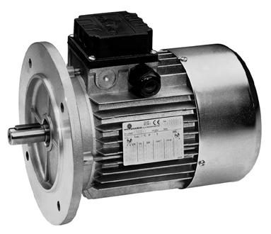
207 AC Motors B14 B5 207
208 AC Motors General Features Three-phase asynchronous electric motors, totally enclosed, fan cooled ventilation, cage rotor in die-cast aluminum alloy or aluminum, insulation class F, protection degree IP 55, standardized height to center and dimensions from 63 to 132, standardized powers from 0.09 to 11kW (0.12HP to15hp). Standard Production Three phase AC motors Three phase AC brake motors Conformity with Reference Standards The standard electric motors conform to the following international standards for rotating electrical machines: IEC 34-1 General requirements for rotating electrical machines IEC 34-2 Test methods to determine losses and efficiency IEC 34-5 Classification of protection degree IEC 34-6 Cooling methods IEC 34-7 Classification of construction shapes and assembly arrangements IEC 34-8 Marking of terminals and direction of rotation IEC 34-9 Noise limit IEC Starting specifications of single-speed three-phase motors for voltages <660V IEC 72-1 Construction dimensions in relation to the nominal power delivered to the shaft IEC 38 Standardized supply voltage For conformity with other standards not mentioned above, contact Motovario for assistance. Conformity with Community Directives CE Marking The standard electric motors are in conformity with the following Directives: 1. Low Voltage Directive 73/23/EEC (19/02/1973) revised by Directive 93/68/EEC (22/07/1993) 2. EMC Directive 89/336/EEC concerning the intrinsic specifications on emissions and levels of immunity 3. Machine Directive 89/392/EEC revised by Directive 91/368/EEC provided the installation has been performed correctly by the machinery manufacturer (in conformity with our installation instructions and with the EN standard Electrical Equipment of Industrial Machinery ) Conformity to the Machinery Directive and to EMC Directive of the complete installation is the exclusive responsibility of the machine manufacturer. Specification UL /C S A Series T TB Three-phase electric motors series T can be manufactured in compliance with standards UL1004 Electric motors and CSA C22.2 No Motors and Generators for the American and Canadian market, respectively. MOTOVARIO UL File E PRGY2 Motors Component MOTOVARIO UL File E194243SP OBJY3 Component Systems, Electrical Insulation MOTOVARIO CSA Certificate (LR ) Class Motors and Generators 208

209 AC Motors Design Features 1. PRELOADED SPRING 2. BEARING ON DRIVING SIDE 3. FLANGE/SHIELD DRIVING SIDE 4. TERMINAL BOX COVER GASKET 5. CABLE GLAND 6. TERMINAL BOARD 7. GROUND SCREW 8. TERMINAL BOX COVER 9. TERMINAL BOX FASTENING SCREWS 10. CASING COMPLETE WITH WINDING 11. SHIELD OPPOSITE TO DRIVING SIDE 12. FAN 13. FAN COVER 14. FAN COVER FASTENING SCREWS 15. KEY 16. BEARING OPPOSITE TO DRIVING SIDE 17. STUD 18. ROTOR WITH SHAFT 19. OIL SEAL 20. FASTENING SCREW FOR TERMINAL BOARD 209
210 AC Motors Design Features Casing Die-cast aluminum alloy, chosen for its high tensile strength and corrosion resistance Finned; casing not painted (painting by request) Fitted with lifting rings starting from size 112 Fitted with or without mounting feet, according to IEC72-1 Fitted with terminal for grounding inside the terminal box. External grounding connection on the motor casing is available. The grounding terminal is marked with the symbol. Flange/ Shield Die-cast aluminum alloy The rear shield is made of cast iron for versions with electromagnetic brake or backstop device By request, it is possible to mount non-standardized flanges (reduced or oversized) Starting from size 100, aluminum shields and flanges have a steel oil seal fitted in the bearing seat; flanges size 160 and larger are made of cast iron. Terminal Box Cover Made of black polycarbonate; die-cast aluminum alloy available by request. IPx6 protection degree is available by request on all versions. Shaft In steel C40 or similar Standardized output shaft and key dimensions according to IEC72-1 Threaded hole on driving end of shaft Double-extended shaft available by request. Rotor The squirrel-cage type rotor is die-cast aluminum or aluminum alloy. The motor is designed so the angle, number of slots and geometric shape of the rotors is relational to the number of stator slots and the polarity of the motor. This design ensures the most regular motor operation even in variable speed applications by decreasing the phenomenon of eddy currents and torque pulses. These phenomena are detrimental to the motor s correct operation and dynamic performance. Rotor balancing, from frame size 80, is performed dynamically with the half-key method in accordance with ISO 2373 standard rating G6.3 for normal vibration. Increased balancing (rating G2.3) is available by request. Stator and Winding Sheet metal with checked magnetic properties Appropriate number of slots and geometric shape in relation to the motor s polarity for regular motor operation Copper winding with double-layer copper glazing G2 degree, H class, capable of providing considerable mechanical strength and ensuring an adequate thermal reserve to slow the aging of the motor Class F insulation system 100% testing of all electrical parameters Bearings Standard bearings are radial ball bearings, standard clearance, 2RS NRB contact seals (with sheet steel reinforcement on both sides of the bearing), lubricated for life. Rear bearings are pre-loaded with a compression ring that acts on the external ring of the bearings. Pre-loading the bearing decreases operating noise and enables axial movement by thermal action. 210
211 AC Motors Design Features Fan Cooling is provided in both directions of rotation by a centrifugal fan with radial blades, keyed externally to the non-drive-end shaft. The standard fan is thermoplastic material strengthened with fiberglass and is suitable for normal motor operating temperatures. The fan can be made of aluminum or anti-static, self-extinguishing material on request. IC411 IC410 Fan Cover The fan cover is galvanized stamped plate, shaped to avoid phenomena of resonance and to improve the airflow developed by the fan. The air feed grille holes are relational to the distance from the accessible rotating parts, in conformity with the safety requirements of the UNI EN 294 standard. Cable Entry Cable Entry and nameplate can be oriented 180 from standard. Standard NPT Adapters 211
212 IP Protection Degree (IEC 34-5) Standard electric motors have protection degree IP55. By request, it is possible to have protection degrees IP56, IP65, or IP66. Protection degrees higher than IP66 cannot be applied. Protection degree of the motors is guaranteed and certified by tests carried out in a qualified testing room. Note: Protection degree, by definition, cannot refer to the oil seal. As an option for IP55 motors, an oil seal on the drive side can be specified, if necessary and by request. Thermal Classification Standard electric motor windings conform with thermal classification F, in accordance with publication IEC34-1. The temperature rise of standard powers does not exceed class B. This results in less thermal strain on the motor insulation for longer motor life. Motors that conform to thermal classification H are available by request, depending on the ambient temperature of the application. Operating Conditions Altitude Standard ratings are based on an altitude of 1000 meters (3281 feet) above sea level (ASL) Ambient Temperature at the Place of Installation Minimum -15 C (5 F), maximum +40 C (104 F). If the motors are destined to operate between 1000m and 4000m ASL, or if the ambient temperature is between 40 C and 60 C (104 F and 140 F), it is necessary to apply a corrective coefficient to the motor power for the motor to maintain its thermal reserve (maximum temperature reached by the windings in normal operating conditions). Other conditions of altitude and/or temperature must be discussed with Motovario Technical Support. A l t i t u de/temperature Corrective Coefficient Humidity The system of impregnation adopted to insulate the motor windings is suitable for temperate climates where the relative humidity of air does not exceed 90%. This treatment is designated Tropicalization T R O P 1. Climatic conditions of the application with higher values of relative humidity (e.g., tropical climates) need additional protection. It is possible to treat the windings with an additional isolating glaze that has excellent resistance to chemical agents: water, acid (10% sulfuric acid solution), alkalis (1% sodium hydroxide), salt water or mineral oils (ASTM-D ). This treatment is designated Tropicalization TROP2. Condensation Drainage Applications that are outdoors, in places with high humidity and/or wide temperature ranges, can be supplied with condensation drainage holes, by request. Plastic caps close the drainage holes to maintain the protection degree stated on the motor nameplate. The drains must be opened periodically to let collected moisture out. The motor operating position must be stated at the time of ordering to position the drainage holes correctly. Anti-Condensation Heaters In the case of motors designated for particularly harsh environments, with extremely low temperatures, high humidity levels and/or extremely wide temperature ranges, it is advisable to use anti-condensation heaters. Low Temperature Applications In case of applications with ambient operating temperature between -50 C and -15 C (-58 F and 5 F), the electric motor can be equipped with special components: Bearings with special lubrication and higher backlash suitable for low running temperatures Silicone oil seal Aluminum fan and terminal box cover Metal plugs and cable glands Such applications could cause condensation and may require TROP2 winding protection, drain holes and anti-condensation heaters. 212
213 Electrical Conditions Supply Voltage and Frequency According to IEC38 the supply voltage for standard three-phase motors is 230/400V with tolerance ±10%; the supply frequency is 50Hz. In agreement with Publication IEC38, operation of standard three-phase motors is ensured in the following voltage ranges where, at 60Hz, the motor supplies power equal to 1.2 times the nominal power at 460V. The nominal values at both 50Hz and 60Hz are given on the motor nameplate. Standard voltage: 230/400V/50Hz ±10%, 230/460V/60Hz ±10% D u t y Duty is defined as the load condition of the application, including starting, electrical braking, operating with no load and rest. The duration and sequence of these factors must also be considered when defining the duty of an application. Duty can be described according to IEC 34-1 standards or by user defined graphs of load condition variables. If the load conditions are not defined, estimate the duration and sequence of the load variables. Do not underestimate the load conditions. If the duty is not stated, S1 service is applied. The motor rating tables (pp ) refer to TEFC motors under normal operating conditions with S1 service. Duty type is printed on the motor nameplate. P r o t e c t i o n All electrical equipment must be protected against damage from trouble or abnormal operation. The following possibilities must be taken into consideration: Over-current from short-circuiting Overload currents Break or decrease in supply voltage Excessive speeds of the elements of the machine For safety reasons, protect against direct contact with live parts and indirect contact with parts normally not live but which could become live in the event of the insulation failing. Bimetallic Thermo-Protector Application and operation: Bimetallic contact N/C (normally closed); N/O (normally open) by request The thermo-protector is inserted directly inside the windings of the motor, which are then formed and impregnated. Three-phase motors have two bimetallic thermo-protectors connected in series and in close contact with the three phases of the winding. The protector ensures the circuit opens quickly without the maximum admitted temperature for the windings being exceeded, in accordance with IEC34-1, depending on the motor insulation class. T h e r m o - p r o t e c t o r s a r e normally used as sensors and control a remote switch that de-energizes the motor. In single-phase motors it is possible to connect the thermo-protector directly to the motor supply and to cut off current i n s t a n t l y. To prevent the supply automatically being restored, prohibited according to EN , it is possible to use a special thermo-protector (type R1) that, in parallel with the bimetallic contact, has a resistor capable of keeping the contact hot even if the motor has cooled, thereby permitting the motor to be restarted only manually with the power switch. Thermistor PTC Thermistors are temperature sensors with high temperature sensitivity. Resistance sharply increases as the temperature approaches the trip level. A release device that protects the equipment can use this signal to de-energize the motor. PT100 The PT100 is a device that varies its resistance increasingly and continuously as the temperature changes. The PT100 is designed to monitor the temperature (i.e.: of the motor windings) with third party electronic equipment. 213
214 Variable Speed A p p l i c a t i o n s Inverter Operating Areas Inverter-driven motors can be categorized in three zones: Zone 1 Constant Voltage/Frequency Ratio Standard motors, 230/400V/50Hz, 400V/50Hz connected in Y to a three phase inverter Standard motors, 230/400V/50Hz, 230V/50Hz connected in to a single phase inverter Standard motors, 230/460V/60Hz, 460V/60Hz connected in Y to a three phase inverter Standard motors, 230/460V/60Hz, 230V/60Hz connected in to a single phase inverter Zone 1 identifies inverter-driven motor operation with constant torque. The lower limit is indicated as f1=25hz for self-ventilated (TEFC or IC416) motor, f1=18-20hz for the forced ventilation motor. Applications requiring lower frequencies are possible, but the motor is then considered de-rated and the nominal torque is not guaranteed. If the current required by the motor will not strain the inverter, the available ratio is 400V/87Hz connected in Y. The magnetic flux in the motor stays virtually constant up to 87Hz. This extends the constant torque zone to 87Hz without saturating the machine and without straining the motor insulation beyond its nominal specifications. Zone 2 Constant Voltage Applications in Zone 2 keep the motor power at a constant value, defluxing the motor as the frequency increases. The upper limit is f2=90-100hz. Above this frequency range, it is physically impossible to decrease the motor flux. This keeps the motor performance constant. Zone 3 An area with constant voltage, with decreasing torque and power. Motor Supply with Inverter Standard three-phase asynchronous electric motors can be used in variable speed applications, supplied with a PWM inverter, while meeting the general requirements for rotating machines established by IEC34-1. Conformity is possible due to the considerable dimensions of the electromagnet and the accurate, high thermal and dielectric margin insulation. This also allows good performance with overloads and limit frequency applications. Do not strain the electric motor s insulation. The motor insulation will not sustain damage if used properly and in conformity with IEC34-1. Heavy duty applications with the motor connected at considerable distance from the inverter and/or with several motors connected in parallel to the same inverter require the user to check the wave shape of the output voltage and use filters to attenuate the harmonic content. These situations imply the use of phase separators between windings (by request for motors up to size 90, standard for sizes ). Please consult with Motovario in these applications. Applications with an extremely high or low speed may require the use of forced ventilation to improve cooling (standard fan cooling is insufficient) and to decrease the noise caused by self-ventilation. Forced ventilation also decreases the load caused by the airflow rate produced by the fan, which is considerable at high speeds. The operating limits of the servo-fan are directly connected to the conditions of load (duration and quantity). Applications at speeds above 3600 RPM are not specified in this publication and must be discussed with Motovario. Sizing the motor correctly for inverter applications is crucial. Please provide detailed information about the application, including the operating voltage value, frequency required, torque and power required, application duration and required ventilation. Careful evaluation of the torque/rpm curve related to the frequency variation and/or voltage variation, as well as the operating details of the application, will allow accurate and correct sizing of the motor. In addition to forced ventilation, motors can be equipped with an incremental encoder to measure position and rpm. Brake motors can be used with an inverter, but only if the power supply of the brake is independent. 1. Extension of the line with constant torque for operation with vector inverter and forced ventilation (IC416), service S1 2. Extension of the curve V/f = constant for operation with vector PWM inverter and forced ventilation (IC416), service S1 3. Typical curve for operation with vector PWM, self-ventilation (IC411) and service S1 4. Extension of the curve as per point 3 for motor operation 230/400V/50Hz, connection Y and V/f=400/87 214

215 C o o l i n g IC416 Forced Ventilation Variable speed motor applications may require forced ventilation (cooling method IC416), using an axial flow servo-fan whose airflow rate is independent of the drive shaft speed. The independent power supply connects directly to the fan cover (single phase version 230V/50-60Hz), or through a separate terminal box cover applied on the fan cover (three phase version 230/400V/50Hz, 230/460V/60Hz). Protection degree of the fan is IP44 and can be supplied in higher protection degrees and/or different voltages. The servo-fan is recommended for motor speeds slower than the nominal speed, when the air flow rate of the standard fan would be i n s u fficient for correct cooling. It is also recommended for motor speeds faster than the nominal speed, when the losses due to ventilation of the standard fan would no longer be negligible compared to the nominal load. The standard motor fan is also very loud at high speed. The speed limits that determine the need for forced ventilation depend on the load conditions subjected to the motor in relation to the speed and type of service. Two pole motors, for example, have a higher airflow rate using the standard fan than the forced ventilation fan. Therefore, the correct use of servo-fan depends on the load (duration and quantity). Forced ventilation fans are supplied as a kit, therefore it is possible to modify a standard self-ventilated electric motor (IC411) into a motor with forced ventilation (IC416) by: Disassembling the standard fan cover, unscrewing the fastening screws from the motor casing Removing the fastening bushing of the plastic fan and prying off the fan Assembling the forced ventilation kit by tightening to the motor casing with the fastening screws of the fan cover 215
216 A c c e s s o r i e s Rain Cover A rain cover is recommended whenever the motor shaft is positioned vertically down and the application is outdoors. The cover attached to the fan housing prevents rain from entering the motor and damaging the windings. The rain cover is recommended whenever damage may result from infiltration of water, partial blockage of the air grill, or an obstruction preventing the fan and the shaft from turning correctly. The cover does not alter the effects of the fan to cool the motor. The application of the cover determines a height variation of the motor. Motor Rain Cover D Backstop Device When reverse motor rotation caused by the dragging action of the load must be prevented, a backstop device can be installed on the motor s fan side. Because of the high rotation speed, backstop devices are not recommended for use with two pole motors. The direction of rotation of the motor (clockwise or counterclockwise) must be stated when ordering for proper motor operation. A label on the fan cover shows the available direction of rotation. The backstop device is sized to withstand the maximum torque transmitted by the motor and to work at the nominal motor speed without excessive wear. The backstop device is also lubricated for life with specific grease. The design of the backstop does not add any dimension to the standard motor. Connection for Fast Response Times Motors can be supplied with a quick connecting adapter to attach power cables easily and safely. The connector has a modular structure so voltage values and current capacities can be adapted according to the motor type. The connector has IP65 p r o t e c t i o n. The motor is supplied with a fixed part (A) incorporated in the terminal box. The detachable part (B) can be supplied by request. The connector can be supplied as: 10-pin connector for standard three-phase motors (series T). Brake motors (series TB) can also be supplied with a 10-pin connector with or without thermal protector unless the brake has an independent AC power supply. Three-phase motors can be supplied with the detachable part (B) with double connection for -Y. 18-pin connector for three-phase brake motor (series TB), with or without thermal protector, internally connected or independently powered AC brake d (mm) p 10-18p d1 (mm) d (mm) d1 (mm) Backstop Device Quick Connection 216
217 C o n n e c t i o n s Terminal Board and Direction of Rotation The connections on the terminal board and the direction of rotation conform to the requirements of the standard IEC34-8. The direction of rotation is defined by observing the motor from the driven shaft side, not the fan side. The standard direction of rotation is clockwise. All standard motors are suitable for operation in both directions of rotation. Connection diagrams are supplied inside the terminal board cover. Three-phase asynchronous motors can operate counter-clockwise (opposite the standard direction) by switching the position of any two power supply leads. The motor warranty is immediately voided if the internal connections of the motor windings to the terminals on the terminal board are altered or changed in any way by the customer. If the motor is designed for just one direction of rotation (see Backstop Device), this working direction is shown with an arrow on the fan cover. Connections Series T The technical data tables of this publication refer to standard three-phase asynchronous motors insulated in class F and in continuous service S1, supplied at the nominal voltage of 266/460V and nominal frequency 60Hz. The admitted tolerance for the voltage is ±10% in accordance with the publication IEC38. Connection diagrams are supplied inside the terminal board cover. Conventional clockwise rotation is obtained by supplying power to the terminals U1-V1-W1. Counter-clockwise rotation is obtained by switching the position of any two power supply leads. Special voltages are available by request (ex. motors 400/690V/50Hz for /Y connections) and/or YY/Y with 9 leads (ex /460V/60Hz for US market). When starting the motor through the standard / Y connection, please verify that the amount of torque needed to start the load is less than the starting torque value, typically about 1/3 of the nominal torque. If the starting torque value is less than the value needed to move the load, the motor will stall. In this instance, please use a higher power motor to ensure smooth operation of the application. 217
218 Brake Motors Brake type MS Operation The MS brake is an AC electromagnetic, spring loaded brake that actuates when the power supply is off. When the brake is energized, the electromagnet releases pressure applied to the brake pads, allowing the motor to turn. Power Supply The brake is powered with 230/400V±10% Vac 50Hz, 230/460±10% Vac 60Hz. Special voltages can be supplied by request. Power supply for TB-MS brake motor series can be internally connected to the motor power supply or independently supplied through a separate terminal board. Internally connected power to the brake is supplied as standard. Please specify when ordering if the power supply needs to be independent. Independent brake power supply for motor sizes 63, 71 and 80 requires an oversize terminal box (please refer to dimension pages). Specifications: Supply voltage 230/400V±10% 50Hz, 230/460±10% Vac 60Hz Service S1, insulation class F Silent friction pads, with no asbestos, with double braking surface Steel brake disk attached with splined driving hub Steel driving hub with vibration-damping system Fixed braking torque in relation to the nominal motor torque (see M B in the motor performance) By Request: Manual release lever with automatic return and removable hand lever. Useful for manual operation in case of voltage drop, power failure or during installation. Hand lever is parallel to the terminal box cover. Lever can be supplied in different positions depending on the application and by request. A small block can be supplied to keep the lever in release position during operation. Protection kit (cover + O-ring) can be supplied to prevent contamination from the surrounding environment and dust produced by friction pad wear. Drive shaft extension manufactured with hexagonal hole set (opposite of driven side) for manual rotation through right hexagonal key (6mm key IEC 63-90, 8mm IEC , 10mm key IEC 132, 12mm key IEC 160). Inox steel ring between motor shield and brake disk with anti-corrosion brake protection and treatments. For harsh environment applications (i.e. outdoor installations). Braking torque adjustable from 35% to 100% of M Bmax through adjusting screws set into the brake body. Micro-switch to verify brake release and block. Connections Alternate current brake 1. When the MS brake is directly connected to the motor power supply, supply cables of the brake are in parallel with those of the motor and set in the same terminal board. The brake coil is automatically energized and the brake is released when power is supplied to the motor. When power to the motor is interrupted, the brake coil is automatically de-energized and the brake is set. During this phase, the braking response time t 2 must be added to delay R, generated by the inertia of the load and by the energy accumulated by the motor. R changes in every motor size. The value of R depends on the load characteristics and cannot be calculated prior to determining the application parameters. 2. When the MS brake has an independent power supply, power is supplied through a separate terminal board. Brake release time t 1 and brake response time t 2 depend only on the brake characteristics. 3. Please contact Motovario for standard t 1 and t 2 values. 218
219 Brake Motors 1. MAGNET BODY 2. MOBILE COIL 3. BRAKE PADS 4. DRIVING HUB 5. RELEASE LEVER (BY REQUEST) 6. PROTECTION COVER (BY REQUEST) 7. THRUST SPRINGS 8. V-RING (BY R E Q U E S T C O M B I N E D WITH PROTECTION COVER) 9. FIXING SCREWS 10. LOCKING NUTS 11. ADJUSTING SCREWS FOR BRAKING TORQUE (BY R E Q U E S T ) 12. KEY 13. CIRCLIP 14. CAST IRON END SHIELD 15. VIBRATION DAMPING SPRING 16. STAINLESS STEEL DISK (BY REQUEST) 219
220 Brake Motors Brake Type FM Operation The FM brake is a DC electromagnetic, spring loaded brake that actuates when the power supply is off. When the brake is energized, the electromagnet releases pressure applied to the brake pads, allowing the motor to turn. Specifications: Power supply 230V±10% 50/60Hz or 400V±10% 50/60Hz Service S1, insulation class F Silent friction pads, with no asbestos, with double braking surface Steel brake disk attached with splined driving hub Steel driving hub with vibration-damping system Fixed braking torque in relation to the nominal motor torque (see M B in the motor performance) By Request: Manual release lever with automatic return and removable hand lever. Useful for manual operation in case of voltage drop, power failure or during installation. Hand lever is parallel to the terminal box cover. Lever can be supplied in different positions depending on the application and by request. A small block can be supplied to keep the lever in release position during operation. Protection kit (cover + O-ring) can be supplied to prevent contamination from the surrounding environment and dust produced by friction pad wear. Drive shaft extension manufactured with hexagonal hole set (opposite of driven side) for manual rotation through right hexagonal key (6mm key IEC 63-90, 8mm IEC , 10mm key IEC 132, 12mm key IEC 160). Inox steel ring between motor shield and brake disk with anti-corrosion brake protection and treatments. For harsh environment applications (i.e. outdoor installations). Braking torque adjustable from 35% to 100% of M Bmax through adjusting screws set into the brake body. Micro-switch to verify brake release and block. Flywheel for starting and progressive braking. Power Supply The brake is powered with direct current by rectifying the input alternate current voltage: For brake motors TB-FM series, standard input voltage is 230Vac rectified via half-wave rectifier bridge for 103Vdc output voltage. A full-wave rectifier bridge can be supplied for 208Vdc output voltage. The brake power is supplied through an internal connection to the motor terminal block as standard. The brake can have an independent power supply, by request. Please specify the brake voltage when ordering an independent power supply. Special voltages available by request, starting from 12Vdc. Possible rectifiers: Half-wave rectifier standard action RV6 (standard in all Motovario TB-FM brakemotors to size IEC 132) Half-wave rectifier standard action low noise NBR (by request to size IEC 132) Half-wave rectifier quick action SBR (by request to size IEC 132, standard for sizes IEC ). Quick release action provided by supplying the brake in the release phase with full-wave voltage instead of half-wave voltage, producing action times between NBR or RV6 rectifier action times and alternate current brake action times. Suitable for applications with high number of cycles where AC brakes are not feasible. Full-wave rectifier - standard detachment DBR (by request to size IEC132). DBR can be used on sizes IEC for short cycles with intermittent service lower than 50%. To house the rectifier, TB-FM motors size IEC 63, 71 and 80 require a larger-than-standard terminal box. Motors without a rectifier (24Vdc brake) or with RV6 rectifier use standard size terminal boxes. All rectifiers conform to Low-Voltage Directive 73/23/CEE. Conformity to EMC Directive (electromagnetic compatibility) 89/336/CEE and its subsequent amendments is achieved by using a low noise rectifier (NBR) in the unit rectifier-brake coil. To filter electrical noise when the DC brake is supplied with half-wave quick action rectifier (SBR) or full-wave rectifier (DBR), connect a 440Vac 0.22 F class X2 capacitor in parallel to the AC power supply in accordance with EN RV6 half-wave rectifier does not have a noise filter and is suitable only when the noise filter is built into the application by the customer. Starting and Progressive Braking TB-FM brake motors can be equipped with a steel hub between the brake and fan, acting as a flywheel to increase the moment of inertia of the system. The flywheel allows softer, more progressive starting and braking for smoother action by adding mass to the motor rotation. The added mass gives the motor a higher moment of inertia, extending the time of action when braking torque is applied. The overall length of the brake motor does not change from standard when it is supplied with a flywheel. 220
221 Brake Motors Connections Direct Current Brake 1. When the FM brake is directly connected to the motor power supply, supply cables on the AC side of the rectifier are in parallel with one phase of the motor and set in the same terminal board. The brake coil is automatically energized and the brake is released when power is supplied to the motor. When power to the motor is interrupted, the brake coil is automatically de-energized and the brake is set. During this phase, the braking response time t 2 must be added to delay R, generated by the inertia of the load and by the energy accumulated by the motor. R changes in every motor size. The value of R depends on the load characteristics and cannot be calculated prior to determining the application parameters. 2. When the FM brake has an independent AC power supply, power to the brake is supplied through power leads separate from the motor power leads. The AC leads of an RV6 rectifier are connected in a fly terminal board mammuth type. NBR, DBR or SBR rectifiers are equipped with AC power supply leads. Braking response time t 2 does not depend on the characteristics of both the motor and load. 3. Faster braking action can be achieved when the FM brake is directly connected to the motor s AC power supply. A switch connected to the rectifier can interrupt brake power on the continuous current side, between the motor terminals and the rectifier. Therefore, the response time of the brake does not depend on the characteristics of the motor and load, but only on the brake characteristics (t 22 < t 2 ). 4. Faster braking action can be achieved when the FM brake has an independent AC power supply. A switch connected to the rectifier can interrupt brake power on the continuous current side, between the input power and the rectifier (t 22 < t 2 ). When the brake has an independent power supply, as in diagrams two (2) and four (4), rectifier life is extended. AC current from the motor windings cannot pass into the rectifier bridge, thus extending rectifier life. Direct DC power can be supplied to the brake by request. A direct DC power supply (i.e. 24Vdc) does not require a rectifier, but does require an independent fly terminal board mammuth type. Brake power supply cables are set inside the terminal box and connected to the secondary terminal board. Time of action is the same as in diagram four (4). If the RV6 rectifier is set with leads for configurations three (3) or four (4) (direct current side), the connection is set by the customer. 221
222 Brake Motors 1. MAGNET BODY 2. MOBILE COIL 3. BRAKE PADS 4. DRIVING HUB 5. RELEASE LEVER (BY REQUEST) 6. PROTECTION COVER (BY REQUEST) 7. THRUST SPRINGS 8. V-RING (BY R E Q U E S T C O M B I N E D WITH PROTECTION COVER) 9. FIXING SCREWS 10. LOCKING NUTS 11. ADJUSTING SCREWS FOR BRAKING TORQUE (BY R E Q U E S T ) 12. KEY 13. CIRCLIP 14. CAST IRON END SHIELD 15. VIBRATION DAMPING SPRING 16. FLYWHEEL (BY REQUEST) 17. STAINLESS STEEL DISK (BY REQUEST) 222


223 N a m e p l a t e s Standard Nameplate UL/CSA Nameplate 223
224 AC Motor Ratings, 6 0 H z 2 Poles 224
225 4 Poles AC Motor Ratings, 6 0 H z 225
226 AC Motor Ratings, 6 0 H z 6 Poles 226
227 8 Poles AC Motor Ratings, 6 0 H z 227
228 063 AC Motor Dimensions B5 B14 Brake Motor 228
229 AC Motor Dimensions B5 B14 Brake Motor 229
230 AC Motor Dimensions B5 B14 Brake Motor 230
231 AC Motor Dimensions B5 B14 Brake Motor 231
232 AC Motor Dimensions B5 B14 Brake Motor 232
233 AC Motor Dimensions B5 B14 Brake Motor 233
234 AC Motor Dimensions B5 B14 Brake Motor 234
235 N o t e s 235
236 N o t e s 236
237 A p p l i c a t i o n s Service Factor The AGMA Classification of service factor depends on the conditions under which the gear reducer operates. Motovario reducers can be rated for operation using the AGMA standards of service, based on AGMA Standard 6019-E89. Class I Reducer Service Factor 1.0 Steady loads not exceeding normal rating and 8-10 hours continuous running time per day. Class II Reducer Service Factor 1.4 Moderate shock loads not exceeding 1.25 x rated load torque and 8-10 hours continuous running time per day. Class III Reducer Service Factor 2.0 Heavy shock loads exceeding 1.25 x rated load torque and 8-10 hours running time per day. Maximum duration of shock is 15 seconds. If shocks are likely to last longer than 15 seconds, please contact Motovario technical service representatives for additional support. Consider ambient temperature when choosing a gear reducer. The service factor determined according to AGMA classification must be corrected for temperature: Ambient Temperature Multiply Service Factor by F F F above 140 F contact Motovario for technical assistance The load classification can also be determined by the following chart: Type of load of the operated machine A Uniform Load fa 0.3 Screw feeders for light materials, fans, assembly lines, conveyor belts for light materials, small mixers, lifts, cleaning machines, fillers, control machines. B Moderate Shocks fa 3 Winding devices, woodworking machine feeders, goods lifts, balancers, threading machines, medium mixers, conveyor belts for heavy materials, winches, sliding doors, fertilizer scrapers, packing machines, concrete mixers, crane mechanisms, milling cutters, folding machines, gear pumps. C Heavy Shocks fa 10 Mixers for heavy materials, shears, presses, centrifuges, rotating supports, winches and lifts for heavy materials, grinding lathes, stone mills, bucket elevators, drilling machines, hammer mills, cam presses, folding machines, turntables, tumbling barrels, vibrators, shredders. fa is defined as: fa = Je/Jm where Je (lb-in 2 ) is the moment of low-speed external inertia at the drive-shaft and Jm (lb-in 2 ) is the moment of inertia of the motor If fa > 10, please contact Motovario for technical assistance. 237
238 A p p l i c a t i o n s Critical Applications Performance ratings correspond to mounting position B3 or similar, i.e. when the first stage is not entirely immersed in oil. For other mounting positions and/or particular input speeds, refer to the tables that highlight different critical situations for each size reducer. It is also necessary to consider the following applications by contacting MotovarioTechnical Service: Use as a speed increaser Use that could be hazardous for people if the reducer fails Applications with high inertia Use as a lifting winch Applications with high dynamic strain on the housing of the reducer In places with ambient temperatures below 23 F or over 104 F. Use in chemically aggressive or caustic environments Use in salty environments Use in radioactive environments Use in environments with pressures other than standard atmospheric pressure Mounting positions not described in this catalog Avoid applications where even partial immersion of the reducer is required. The maximum torque that the gear reducer can support must not exceed two times the nominal torque (when service factor = 1.0) stated in the performance tables. Maximum torque considers momentary overloads at full load start-up, braking, shocks or other causes, particularly dynamic shock. 238
239 Overhung Load Overhung Load (OHL) The overhung load on the shaft is calculated as: Where: Fre (lbs) is the resulting overhung load M (in-lbs) is the torque on the shaft D (in) is the pitch diameter of the transmission member mounted on the shaft Fr (lbs) is the value of the maximum permissible overhung load (see relative tables) fz = 1.1 gear pinion 1.4 chain wheel 1.7 v-pulley 2.5 flat pulley When the resulting overhung load is not applied on the center line of the shaft, the overhung load on the shaft is calculated as: a, b, x = values given in the tables on pages 240 and 241. The value of the permissible overhung load (lbs) is given in the tables relating to the performance of the reducer in use. It is related to the load applied on the center line of the shaft and in the most unfavorable conditions of angle of application and direction of rotation. The maximum admissible thrust loads are 1/5 (20%) of the value of the given overhung load when they are applied in combination with the overhung load. The tables relating to the output shafts give the maximum permissible value. This value must never be exceeded since it relates to the strength of the reducer housing. Particular conditions of overhung load higher than the limits listed in this catalog may occur. In this case, call Motovario Technical Sevice and provide details on the application: (direction of the load, direction of output shaft rotation, type of service). 239

240 Overhung Load Overhung Load, Output 240
241 Overhung Load Overhung Load, Input 241
242 Physical Properties Paint Motovario SmartBox products are supplied with the following surface treatments: De-burring by mechanical shearing system Accurate shot-peening Painting Washing and passivation Die-cast materials are always painted. Paint used on Motovario reducers meets the following specifications: Orange-peel blue-colored epoxy-polyester RAL 5010 Polyester resin based heat-hardening powders, altered with epoxy resins, applied by electrostatic spray Heat resistance: 24 hours at 150 C (302 F) Corrosion strength: ASTM B 117/97 salt fog from 100 to 500 hours, depending on the surface s preliminary treatment Non-toxic and non-irritating according to EEC directives no. 67/548 regarding dangerous substances and no. 88/379 dangerous compounds Tests carried out on degreased Unichim white lattens (film thickness: 60 microns) comply with the following specifications: o Adherence (ISO2409) o Erichsen drawing (ISO152) o Inverted shock (DIN53158) o Cone-shaped mandrel (DIN53151) o Hardness (ASTM D3363/74) 242
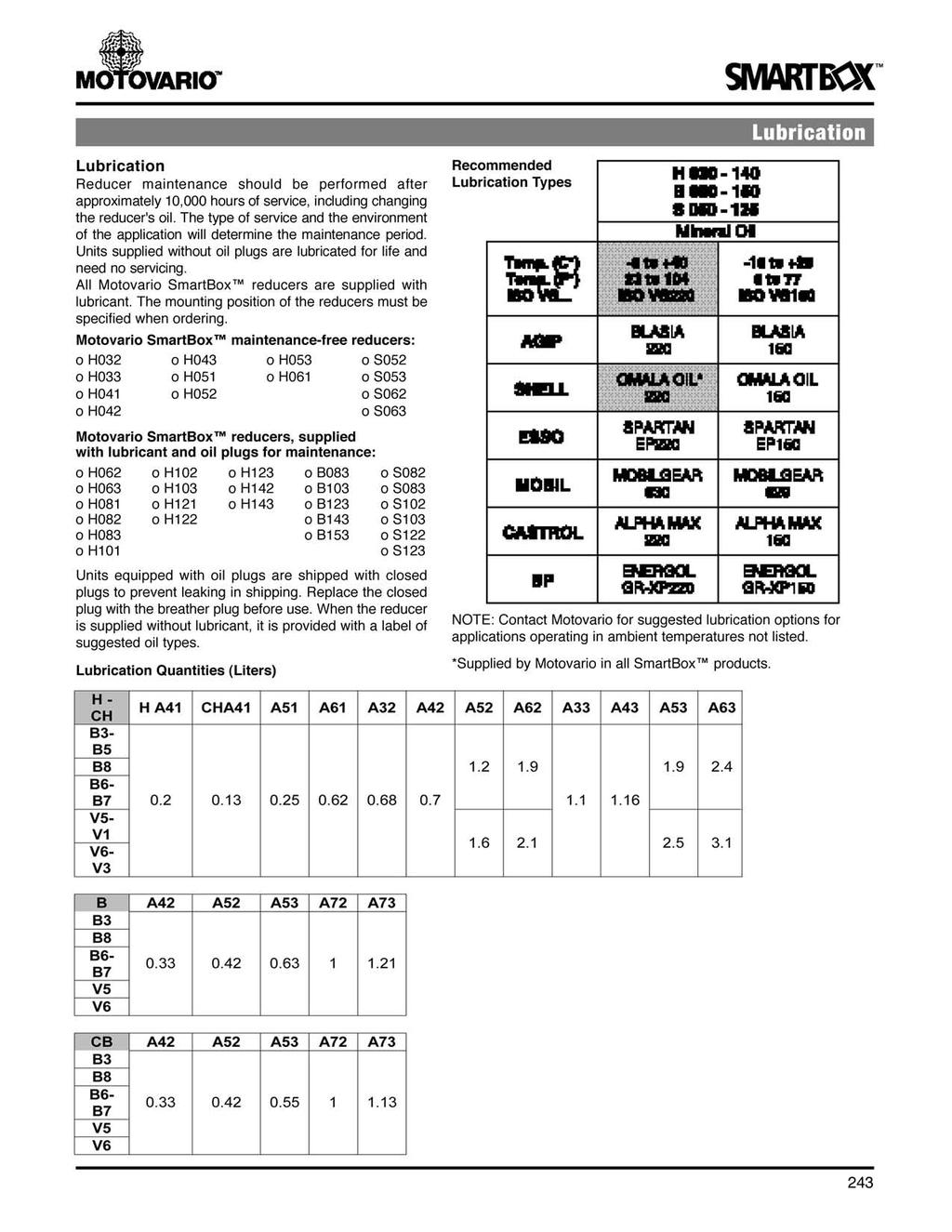
243

244 We i g h t s H Series SmartBox Weights (lbs) Weights are close approximations, rounded to the nearest pound. Weights do not include additional accessories. Weights include lubrication. 244


 S")

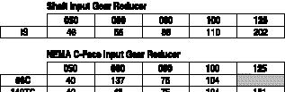
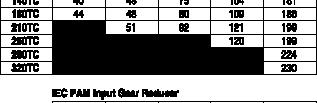
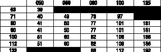
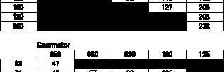
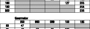

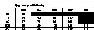
245 We i g h t s B Series SmartBox Weights (lbs) S Series SmartBox Weights (lbs) Weights are close approximations, rounded to the nearest pound. Weights do not include additional accessories. Weights include lubrication. 245
246 Installation and Use Recommendations for SmartBox installation: Avoid vibration by mounting the reducer securely to the application. Check the direction of rotation of the reducer output shaft before fitting the unit to the application. If the reducer is stored for long periods (4-6 months or more), make sure the oil seals are in contact with the reducer s internal lubricant. If the oil seal cannot contact the reducer s lubricant, change the oil seal before use. The seal s rubber coating may stick to the shaft or may lose the elasticity necessary to function properly. Mount hollow output shaft reducers with Motovario torque arms or output flanges. If Motovario mounts are not available, make sure the application allows for movement of the reducer. Whenever possible, protect the reducer against solar radiation and bad weather. Ensure the motor cools correctly by allowing air to flow freely on the motor s fan side. When ambient temperatures are below -5 C (23 F) or above 40 C (104 F), contact Motovario for assistance. Pulleys, sprockets, couplings, shafts and other output devices must be securely mounted on the solid or hollow shafts. Use threaded holes or similar locking methods to ensure correct operation without risking damage to the bearings or external reducer parts. Lubricate all surfaces in contact to avoid seizure or oxidation. Rubber parts (seals and o-rings) and the holes on the breather plugs (if applicable) must not be painted. Units equipped with oil plugs are shipped with closed plugs to prevent leaks during shipping. Replace the closed plug with the breather plug before use. Check for the correct level of the lubricant through the sight glass (if applicable). Do not immediately apply the maximum application load. Start-up slowly whenever possible. Take extra precautions when there are parts, objects, materials or people under the reducer that can be damaged by any oil leak. Applications operating in ambient temperatures below -30 C (-22 F) or over 60 C (140 F) require special oil seals. Applications operating in ambient temperatures under 0 C (32 F) have special needs: o Motors must be suitable for operation at the ambient temperature. o Colder temperatures require more starting torque from the motor. The motor power must be adequate to exceed the required starting torque. o Cast iron becomes fragile and brittle in temperatures under -15 C (5 F). The viscosity of the reducer lubrication is higher at start-up. Whenever possible, run the reducer under no load for a few minutes to decrease oil viscosity. Installations and maintenance guides are available from Motovario or at Motor Coupling Installation Motovario SmartBox reducers designed for c-face motors use a flexible motor coupling design to maximize start and stop shock load capacity. The Hytrel component of the coupling absorbs the shocks associated with harsh starts and stops. Motovario s motor coupling is designed to fit simply over the motor shaft for easy installation. When installing, make sure the motor shaft, pilot and flange are free of oil, dirt, paint or other contaminants. The motor key must fit securely to the motor shaft before installing the coupling. The coupling will fit against the motor shaft s shoulder, keeping the coupling securely in place. Fit the flexible coupling element to the motor coupling and position the motor and reducer together. Align the flexible component with the reducer component. Secure the motor to the reducer by bolting it to the input flange. Instruction sheets for IEC and NEMA motors are available from Motovario or at 246
247 Installation and Use Shaft Construction Motovario customers can mount the SmartBox B and S series directly on to the drive shaft of their application. The drive shaft must be manufactured according to the dimensions shown in the following diagrams. Not following these dimensions can lead to shaft deformation, inability to service or remove the reducer from the application or cancellation of the factory warranty. The suggested length of the drive shaft from the shoulder to shaft-end is dimension V. The shaft length must be greater than dimension VA on standard shaft units; greater than or equal to dimension V on shrink disk units. The drive shaft must be manufactured with a shoulder in order to mount the reducer securely. The reducer must be fixed to the application using a torque arm, output flange, mounting feet or by other means of stabilizing the reducer. If the reducer cannot be fixed, make sure the application allows for movement of the reducer assembly. Check the output rotation of the reducer before mounting to the application. Lubricate all metal surfaces that come in contact to avoid seizure and oxidation. Install the locking kit (retaining bolt, stainless steel washer and optional rubberized washer) to secure the drive shaft and reducer together. Use a rubberized or plastic washer inside the stainless steel washer to seal the hollow output bore from intrusion by water, dust or other contaminants. Do not over-tighten the retaining bolt so as to deform the washer. The locking kit will rotate with the drive shaft. Keep away loose items that may become tangled in the locking kit. Do not immediately apply the maximum load of an application. Start slowly whenever possible. 247


248 Installation and Use Shaft Construction B Shaft Dimensions S Shaft Dimensions 248

249 Installation and Use Shrink Disk Shaft Construction B Shrink Disk Shaft Dimensions S Shrink Disk Shaft Dimensions 249
A p p l i c a t i o n s
 A p p l i c a t i o n s Service Factor The AGMA Classification of service factor depends on the conditions under which the gear reducer operates. Motovario reducers can be rated for operation using the
FEATURES / BENEFITS... 2 SPECIFICATION / HOW TO ORDER... 4 NOMENCLATURE... 11
 CONTENTS QUANTIS RHB FEATURES / BENEFITS.................................... 2 SPECIFICATION / HOW TO ORDER........................... 4 NOMENCLATURE......................................... 11 GEARMOTORS
Product Brochure. Quantis gearmotors & reducers
 Product Brochure Quantis gearmotors & reducers We provide motors, generators and mechanical power transmission products, services and expertise to save energy and improve customers processes over the total
APG Updated APG
 MASTER CONTENTS Updated 5-24-2017 Contents Features / Benefits...-2 Specification...-4 How To Order...-4 Nomenclature...-6 Selection Gearmotors... -7 C-Face and Separate Reducers... -25 Dimensions Gearmotors...
HSERIES. Helical geared motors
 HSERIES Helical geared motors Design features Motovario products are supplied with the following surface treatment features: Die-cast aluminium alloy cases for gears Die-cast materials undergo the following
DC MOTORS NEMA FRAME SCR RATED
 NEMA FRAME SCR RATED NEMA FRAME MOTORS SCR RATED High voltage permanent magnet DC motors are typically used with an SCR (thyristor) controller in applications requiring adjustable speed and constant torque
B SERIES. Helical bevel Gear Reducers
 Helical bevel Gear Reducers FEATURES The technological content of -Series gear reducers allows for an extraordinary performance/lifespan ratio. These highly versatile gear units are successfully used in
.1 Standard Features NORDBLOC.1 SERIES. Intelligent Nordbloc Drivesystems. Innovative Design F1012
 Intelligent Nordbloc Drivesystems.1 Standard Features NORDBLOC.1 SERIES F1012 Bearing Design The design of the bearing systems is a key innovation in the new NORDBLOC.1 units. The output bearing is greatly
180VC WITH B5 FLANGE / M ,6 0, / M l 5,0 0,7 192 / M ,0 0,9 223
 METRIC (IEC) FRAME THYRISTOR RATED DC METRIC (IEC) FRAME MOTORS IP54 These metric dimensioned motors are built to IEC 34-1 electrical and mechanical standards. The IEC 63 and smaller frames are stocked
2000HG SELECTION AND PRICING
 2000HG SELECTION AND PRICING Sterling Electric offers a full range of Helical Gear Products to meet the demanding applications found in today s industry. Our standard cast iron product design lends itself
Speed Reducers and Gearmotors
 ofc BEVEL BUDDYBOX Speed Reducers and earmotors CATALO 13.605.50.001 Bevel Buddybox Rugged Spiral Bevel Output Modular Cyclo Input Compact Size Two-Year Warranty Eccentric Cam and Roller Assembly Housing
Grove Gear IRONMAN High Effiiciency Helical - Bevel Gear Reducers
 Grove Gear IRONMAN High Effiiciency Helical - Bevel K Series Features and Benefits standard double lip Seals provide extra protection against entry of contaminants or loss of lubrication. Bearing spans
MTF. Technical features
 Technical features Power supply Three-phase voltage from 24V to 690V, 50Hz or 60Hz or 100-130V, 60Hz and 200-240V, 50Hz ( types are supplied without capacitor); suitable for use with an inverter from 20Hz
MTF-E. Technical features
 Technical features Power supply Threephase voltage from 220V to 690V, 50Hz or 60Hz; suitable for use with a PM inverter from 20Hz to the base frequency with constant torque load profile. Polarity 2 and
Highly Efficient, Grease Lubricated, Compact Design. Hypoid gearing delivers efficiencies up to 85% and smooth, quiet operation
 Highly Efficient, Grease Lubricated, Compact Design Grease lubricated design is maintenance free, requires no oil changes and is up to 85% efficient across all ratios Hypoid gearing delivers efficiencies
MECHANICAL POWER TRANSMISSION. Quantis gearmotors & reducers
 MECHANICAL POWER TRANSMISSION Quantis gearmotors & reducers 2 DODGE MECHANICAL QUANTIS GEARMOTOR Dodge Quantis We provide motors and mechanical power transmission products, services and expertise to save
THE INNOVATIVE TEAM IN POWER TRANSMISSION
 S m a l l WONDER THE INNOVATIVE TEAM IN POWER TRANSMISSION 2 1 2 The output shaft is constructed from quality C40 steel for maximum output torque. The corrosion-resistant aluminum surface cools easily
GROVE GEAR IRONMAN HIGH EFFICIENCY HELICAL-BEVEL GEAR REDUCERS K SERIES FEATURES AND BENEFITS
 GROVE GEAR IRONMAN HIGH EFFICIENCY HELICAL-BEVEL GEAR REDUCERS K SERIES FEATURES AND BENEFITS standard double lip Seals provide extra protection against entry of contaminants or loss of lubrication. Bearing
CYCLO HBB. ofc. Gearmotor. Premium Efficient Motor Edition. Catalog
 ofc CYCLO HBB HELICAL BUDDYBOX Gearmotor Premium Efficient Motor Edition Catalog 07.401.90.001 Helical Buddybox EP.NA Motors Enhanced Performance (EP.NA) integral motors represent exceptional value to
MVSI-TS. Split covers. Technical features
 MVSI-TS Split covers The MVSI-TS series, obtained directly from the MVSI series, is characterized by the split weight covers. The weight cover is divided into two halves that can be removed in a radial
900 SERIES. Specifications. Features
 900 SERIES Over 350 models in stock, a 24-hour Quick Ship program on most popular non-stock items, and 35 warehouses throughout North America Baldor gives you the features you want, where and when you
7 Important information on selection tables and dimension drawings
 Possible geometrical combinations Important information on selection tables and dimension drawings. Possible geometrical combinations.. Structure of the tables These tables show geometrically possible
steel standard SST DUCK components Epoxy Resin Rated Insulation System recognized stainless steel output shaft seal
 Premium Efficiency Washguard Motors - Now Available! WASHGUARD MOTORS WASHGUARD MOTORS AVAILABLE IN FIVE STYLES Maximum service in critically clean or corrosive environments PREMIUM WASHGUARD ALL-STAINLESS
SHAFT MOUNT & SCREW CONVEYOR REDUCERS. Cleveland
 SHAFT MOUNT & SCREW CONVEYOR REDUCERS Cleveland SHAFT MOUNT & SCREW CONVEYOR REDUCER FEATURES Shaft Mount reducers available in sizes 2 Screw Conveyor reducers available in sizes 2 6 Suitable for AGMA
DODGE QUANTIS MAKES THE GLOBAL CONNECTION
 DODGE QUANTIS MAKES THE GLOBAL CONNECTION HOLLOW SHAFT SOLID SHAFT DOUBLE ENDED SOLID SHAFT HOLLOW SPLINED SHAFT SHRINK DISK CONNECTION SHAFT RHB FOOTLESS FLANGE RHB FOOT MOUNTED NE SEPARA ARATE C Output
A REGAL-BELOIT COMPANY. More Than Just a Motor Company WASHGUARD WASHDOWN DUTY PT PRODUCTS ELECTRIC MOTORS, GEARMOTORS AND DRIVES.
 A REGAL-BELOIT COMPANY More Than Just a Motor Company WASHGUARD WASHDOWN DUTY PT PRODUCTS ELECTRIC MOTORS, GEARMOTORS AND DRIVES Bulletin 1500 WASHGUARD WHITE EPOXY Enhanced Performance in Wet, Humid Areas
technology made in Italy
 technology made in Italy GB RD * * VS made in China Technology Made in Italy Since 1955 Varvel has been making speed reducers and variators for light industry applications. Reliable partner in power transmission
GROVE GEAR IRONMAN HIGH EFFICIENCY HELICAL-INLINE GEAR REDUCERS & GEAR+MOTOR SOLUTIONS
 GROVE GEAR IRONMAN HIGH EFFICIENCY HELICAL-INLINE GEAR REDUCERS & GEAR+MOTOR SOLUTIONS R SERIES FEATURES AND BENEFITS ALL GEARING is HARDENED AND GROUND (AGMA class 10 or better) for enhanced efficiency
Technical features Certifications
 The MVSI series represents the line of reference products for manufacturer s of vibrating machines and plants operating in many industrial sectors and is made up of the largest range on the market, with
Intelligent Drivesystems NORD GRIPMAXX. Keyless Bushing System DRIVESYSTEMS F5210
 Intelligent Drivesystems NORD GRIPMAXX Keyless Bushing System F5210 The NORD GRIPMAXX Keyless Bushing System Concept Overview The NORD Gripmaxx Bushing System offers keyless interchangeable bushings for
Grove Gear Ironman High Efficiency Helical - Inline Gear Reducers and GEAR+MOTOR Solutions
 BRAVO Grove Gear Ironman and GEAR+MOTOR Solutions R Series Features and Benefits ALL GEARING is HARDENED AND GROUND (AGMA class 10 or better) for enhanced efficiency and noise reduction. Double reduction
Helical Gear Motors BEGE Type G & M. Your drive, our (trans)mission. BEGE Power Transmission
mission. BEGE Power Transmission") Helical Gear Motors BEGE Type G & M BEGE Power Transmission Anton Philipsweg 30 2171 KX Sassenheim The Netherlands T: +31 252-220 220 E: bege@bege.nl W: www.bege.nl Your drive, our (trans)mission General
Helical Gear Motors BEGE Type G & M BEGE Power Transmission Anton Philipsweg 30 2171 KX Sassenheim The Netherlands T: +31 252-220 220 E: bege@bege.nl W: www.bege.nl Your drive, our (trans)mission General
2009 CUSTOM CLASSICS CATALOG
 2009 CUSTOM CLASSICS CATALOG CONTENTS DODGE Custom Classics Introduction D1-1 - D1-4 Introduction DODGE APG D2-1 - D2-88 MASTER XL D3-1 - D3-96 DODGE Combination TIGEAR D4-1 - D4-87 REEVES MOTODRIVE D5-1
SERIES 12 SUB-FHP RIGHT ANGLE DC GEARMOTORS
 SERIES 12 SUB-FHP RIGHT ANGLE DC GEARMOTORS SERIES 12 SUB-FHP Electrical Specifications: Both SCR (90 volt) and Low Voltage (12 volt) right angle gearmotors. the 90 volt motors are performance matched
MASTER SPECIFICATION XL RIGHT ANGLE GEARING XL PARALLEL GEARING
 SPECIFICATION XL RIGHT ANGLE GEARING The speed reducer shall be suitable for integral gearmotor construction, readily adaptable for C-face mounting, in either integrally cast feet, output flange, multi-mount,
MASTER SPECIFICATION XL RIGHT ANGLE GEARING XL PARALLEL GEARING
 SPECIFICATION XL RIGHT ANGLE GEARING The speed reducer shall be suitable for integral gearmotor construction, readily adaptable for C-face mounting, in either integrally cast feet, output flange, multi-mount,
NEMA & IEC Product Features and Benefits
 NEMA & IEC Product Features and Benefits BEAUTY BENEATH THE SURFACE. Looking at a Techtop electric motor, it would be understandable if you thought it was just another NEMA or IEC squirrel-cage induction
PARAMAX Series. Agitator Drives CW11
 PARAMAX Agitator Drives 9000 Series CW No. G60E-.0 No. G60E- Agitator Drives Features.Easy to mount Flange mounting Compact gearbox allows simpler mounting base. Oil pump requires no electricity..compact
The Best Value in Washdown Duty Motors and Drives
 The Best Value in Washdown Duty Motors and Drives Long before we invested in the people, equipment and material required to produce Baldor Reliance Washdown Duty motors and drives, we invested our time
BSERIES. Helicalbevel GearReducers
 Helicalbevel GearReducers Features The technological content of B-Series gear reducers allows for an extraordinary performance/lifespan ratio. These highly versatile gear units are successfully used in
DC Motors. DC Motors. Gearmotors. AC / DC Controls. Accessories / Kits. Mods / Factory Options. X-Ref / Index. Tech. Information.
 Motors Motors Gearmotors AC / s Accessories / Kits, explosion proof, SUB-F, washdown, IEC and low voltage motors available Permanent magnet designs PWM or SCR rated and low voltage input voltage designs
2 Important Information, Tables and Dimension Sheets
 Permitted combinations Important Information, Tables and Dimension Sheets.1 Permitted combinations Structure of tables These tables show combinations of gear units and AC (brake) motors that are geometrically
Series 2000 Inline Helical Gear Drives & Gear Motors
 A L T R A I N D U S T R I A L M O T I O N Series 2000 Inline Helical Gear Drives & Gear Motors INTRODUCING NEW GEARING SOLUTIONS FROM BOSTON GEAR This well recognized Altra Industrial Motion brand has
QUICK REFERENCE Stock Sub-FHP Gearmotors
 Parallel Shaft PZ Series QUICK REFERENCE Stock Sub-FHP P240 & P300 Series AC Single & Three Phase Single Phase 115V 12-100 In-Lbs Page 102 Single Phase 115/230V 43-391 In-Lbs Page 103 DC SCR & Low Voltage
MVSI. Technical features
 MVSI The MVSI series represents the line of reference products for manufacturer s of vibrating machines and plants operating in many industrial sectors and is made up of the largest range on the market,
2 Product Description and Overview of Types
 General information Product Description and Overview of Types. General information Power and torque The details on power and torque given in the catalog refer to mounting position M and similar mounting
Dodge Torque-Arm II The Legacy Continues
 Torque-Arm II Dodge Torque-Arm II The Legacy Continues The Dodge Torque-Arm II surpasses all other reducers on the market because of its industry proven design and patented features. This powerful line
HAIE2 -Efficiency and reliability for industry
 HAIE2 -Efficiency and reliability for industry High performance with energy efficiency, this is the meaning of the new CAG electric motor. Low cost and best quality and long lifetime have been the basis
QUICK REFERENCE Stock Sub-FHP Gearmotors
 QUICK REFERENCE Stock Sub-FHP AC Single & Three Phase DC SCR & Low Voltage Parallel Shaft PZ Series Single Phase 115V 12-100 In-Lbs Page 166 DC SCR 90 & 180V 10-100 In-Lbs 36-100 In-Lbs torque Page 156
LEESON Your Complete Source For Quality DC Motors And More
 LEESON Your Complete Source For Quality DC Motors And More Today s LEESON offers one of the industry s broadest and most accessible ranges of AC and DC commercial and industrial electric motors, gearmotors,
The Original Domed Crown unique rounded housing prevents foreign matter adherence and fluid accumulation. Energy Efficient Design
 SS2000 Series Helical Inline Gear Drives B1 Integrated o-rings Laser marked nameplate provides worry-free part identification while maintaining a smooth, unetched surface 3-Jaw Coupling NEMA or IEC C-Face
Helical Gearmotors and Speed Reducers.
 Helical Gearmotors and Speed Reducers www.diequa.com available from DieQua Corporation DieQua Corporation is a manufacturer and supplier of premium quality power transmission and motion control components,
General Purpose Three Phase Motors TEFC (IP55) High Efficiency. Standard Features
 High Efficiency. Standard Features") TM WEG W21 Severe Duty motors meet the most demanding severe duty application requirements. These TEFC motors are all cast iron construction, with enclosures rated IP55 to handle wet and dirty environments.
TM WEG W21 Severe Duty motors meet the most demanding severe duty application requirements. These TEFC motors are all cast iron construction, with enclosures rated IP55 to handle wet and dirty environments.
Protection against mechanical impacts IK 08 according to IEC 68, EN Insulation class Class F (155 C), class H (180 C) on request.
, class H (180 C) on request.") MVSI The MVSI series represents the line of reference products for manufacturer s of vibrating machines and plants operating in many industrial sectors and is made up of the largest range on the market,
MVSI The MVSI series represents the line of reference products for manufacturer s of vibrating machines and plants operating in many industrial sectors and is made up of the largest range on the market,
What s New in This Catalog. Stainless Steel H
 What s New in This Catalog S Stainless Steel H At The Heart Of What Drives Your World... Since 1892, HUB CITY has a reputation for producing tough, dependable driveline components for industry and agriculture
Gearmotors Parallel Shaft - PZ Series - DC
 90 & 180 - TENV - PZ Series Price Model Frame P X XL XH 4 40 1 40 M1115002.00 496 985.620 PZ5-30A 450 90 0.46 155 3.00 3.25 9.28 7.72 S, US 40 1 40 M1125046.00 496 985.623 PZ5-30A 450 180 0.19 155 3.00
Brake Motors Aluminium Frame Improved Efficiency EFF2
 Motors Energy Automation Coatings Brake Motors Aluminium Frame Improved Efficiency EFF2 Standard Features: Three-phase, multivoltage, IP55, TEFC Output: 0.12 up to 11kW Frames: 63 up to 132M Voltage: 220-240/380-415V
Helical - Inline Interchange Base Selections
 BRAVO Helical - Inline Interchange Base Selections BRAVO Accessory Kits Size 717 Interchange Base Selections Mod-Squad Codes Accessory Kits Base Mounting Dimensions Motorized Quill Input Mod-Squad Critical
GROVE GEAR PRODUCTS BROCHURE
 GROVE GEAR PRODUCTS BROCHURE A Multitude of Applications Chemicals Processing Meat GR Series Worm Gear Reducers EL Series Worm Gear Reducers SS Series Worm Gear Reducers Fourteen sizes available with ratings
MINA-GEAR GEARMOTORS P-1. Mina-Gear Features... P-2 Application & Selection... P-3 Right-Angle Worm Gearmotors Series Parallel Shaft Gearmotors
 MINA-GEAR GEARMOTORS Mina-Gear..................................................... -2 Application & Selection................................................... -3 Right-Angle Worm Gearmotors 2100 Series
Power Transmission solutions for every
 Power Transmission solutions for every IRONMAN GR Series Stainless Steel ironman High Efficiency Gear Reducers washguard Recognized throughout the world as a leader in industrial-duty gear reducers, GEAR+MOTORS
Cyclo Modular System General Information Gearmotors General Information Helical Buddybox Type Designation... 12
 Front Cover Buddy Box In preparing our new catalogue we have made every effort to present the information in a clear and concise manner. We hope you will find the format to be satisfactory, enabling you
Washguard Industrial-Duty Electric Motors
 Washguard Industrial-Duty Electric Motors LEESON Electric 1051 Cheyenne Ave. Grafton, WI 53024 PH: 262-377-8810 FAX: 262-377-9025 www.leeson.com A Regal Brand www.regalbeloit.com The motor line that stands
CUSTOM DC MOTORS & GEARMOTORS
 & GEARMOTORS Battery-powered, 24-volt motor with close coupled hydraulic pump mounting on one end and standard NEMA 56 C face and shaft on other end. Totally enclosed fan cooled, thyristor rated, partial
W22 NEMA Brake Motors - NEMA Premium
 101 www.pamensky.com TEFC Standard Features Motors are compliant with DOE and NRCAN Three-phase, 2, 4, 6 and 8 pole, 60Hz Voltage: 208-230/460V, 575V Brake power supply: 220/230/240/460/575V Totally Enclosed
ALUMINUM RATIO MULTIPLIERS
 More Than Just a Motor Company ALUMINUM RATIO MULTIPLIERS Bulletin 7052 FEATURES 7 5 1 2 3 9 6 8 4 10 1 2 3 4 Lightweight Aluminum Construction is up to 75% lighter and 35% smaller than cast iron reducers
Hub City Spartan Aluminum Worm Gear Drives
 Spartan Aluminum Worm Gear Features C-2 Selection Instructions C-3 Descriptions C-4 Single Reduction Ratings C-5 Single Reduction Dimensions C-6 to C-7 Double Reduction Worm-Worm Ratings C-8 Double Reduction
All Products Catalog We Provide Solutions
 All Products Catalog We Provide Solutions A Regal Brand We Listen Define your critical application and business needs, and we ll help you determine the right path to success. and Provide Solutions. We
Falk V-Class Gear Drives Overview. Falk V-Class Gear Drives
 Falk V-Class Gear Drives Overview Falk V-Class Gear Drives Since its creation, the Falk V-Class has set and maintained a new standard in gear drives. Extreme industrial applications demand a gear drive
8 Important Information about Tables and Dimension Sheets
 Geometrically possible combinations Important Information about Tables and Dimension Sheets.1 Geometrically possible combinations Structure of the tables These tables show combinations of gear units and
SERIES NEW PARALLEL HELICAL AND BEVEL HELICAL GEARBOXES PARALLEL HELICAL AND BEVEL HELICAL GEARBOXES
 SERIES NEW PARALLEL HELICAL AND BEVEL HELICAL GEARBOXES PARALLEL HELICAL AND BEVEL HELICAL GEARBOXES 1 2 SERIES 1 2 pag. pag. 5 Introduction Features 3 pag. pag. Versions Range and designation 5 pag. 9
technology made in Italy RS RT
 technology made in Italy RS RT * * VS made in China Technology Made in Italy Since 1955 Varvel has been making speed reducers and variators for light industry applications. Reliable partner in power transmission
CleanLine UltraPlus. Spartan Worm Gear Drives. Poweratio 2000 & 4000
 CleanLine UltraPlus Patent Pending Ultimate Pharmaceutical, Food and Meat Processing and Washdown Solutions! See Section O Spartan Worm Gear Drives Compact, Rugged and Lightweight Alternatives for Design
WGM SERIES WORM GEARED MOTORS WGM 063 FA 30 DI SO Φ25 PAM80B14 B3
 WORM GEARBOXES WORM GEARBOXES page 2 of 17 WGM SERIES WORM GEARED MOTORS BRIEF INTRODUCTION Our worm gear speed reducers range WG and WGM are characterized by a kinematic motion made of a casehardened
CONTENTS. DODGE QUANTIS Gold Gearmotors
 CONTENTS DODGE QUANTIS Gold Gearmotors QUANTIS Features / Benefits........................................................... QG-3 How to Order / Nomenclature...................................................
Stock Product Quick Reference Guide
 Stock Product Quick Reference Guide A Regal Brand Thousands of solutions. One matched perfectly to your needs. More than 6,000 stock motors, gearmotors, gear reducers and control designs available. Yes,
MAX-VH. Vertical Hollow Shaft Motors
 MAX-VH Vertical Hollow Shaft Motors Specifications OTHER PERFORMANCE CONSTRUCTION APPLICATION RATING Item Type Of Motors Design Standards Voltages Frequency Output Range RPM (SYN.) Time Duty Frame Size
STOBER Drives Inc., Maysville KY
 STOBER Drives Inc., Maysville KY Total Cost of Ownership The total cost of owning any product is more than the original price that is paid. In the event of a breakdown or other catastrophe, many factors
Data sheet. Etaline GN /1852 G10 Version no.: 1 Inline pump. Operating data. Design. Requested developed head m
 Data sheet Item no.: 2600 Page: 1 / 5 Operating data Requested flow rate 40.00 m ³/h Actual flow rate 40.00 m ³/h Requested developed head 68.00 m Actual developed head 68.00 m Pumped medium Water Efficiency
Aluminium Frame Motors Improved Efficiency EFF2
 Motors Energy Automation Coatings Aluminium Frame Motors Improved Efficiency EFF2 Standard Features: Three-phase, multivoltage, IP55, TEFC : 0.12 up to 11kW Frames: 63 up to 132M Voltage: 220-240/380-415V
Fulfilling your needs & Safe
 MEETING CZEPJ Industrial plugs and sockets Fulfilling your needs & Safe Pavel Mony, product management Plug and socket What s on the cable Connecting building and equipment Socket Connector Inlet Plug
7 Selections and dimensions - Overview
 Error! Bookmark not defin ed. Selections and dimensions - Overview Possible combinations table Selections and dimensions - Overview.1 Possible combinations table These tables show the possible physical
2000HB K-SERIES HELICAL BEVEL GEAR REDUCER
 2000HB K-SERIES HELICAL BEVEL GEAR REDUCER INSTALLATION AND MAINTENANCE MANUAL January 22, 2018 7997 Allison Avenue, Indianapolis, IN 46268 Website: www.sterlingelectric.com (800) 866-7973 FAX (317) 872-0907
More Than Just a Motor Company
 More Than Just a Motor Company RIGHT-ANGLE AND PARALLEL SHAFT AC & DC GEARMOTORS FRACTIONAL AND SUB-FRACTIONAL HORSEPOWER Bulletin 1830 GEARMOTORS Your First Source for Off-The-Shelf or Custom Gearmotors
Gearboxes. Gearboxes
 254 Brammer provide a comprehensive nationwide industrial repair service. Strategically located Gearbox Centres around the UK Complete service from emergency repair or gearbox replacement to scheduled
Construction Enclosure coupling and elbow coupling fittings are die-cast from G AL SI 12 aluminum. Suspension tubing is steel.
 Tara Plus Measurement Conversions 1 kg = 9.81 N 1 lb = 4.44 N e.g. 500 Newtons = 51 kg = 112.4 lbs 300 Newtons = 30.6 kg = 67.4 lbs 100 Newtons = 10.2 kg = 22.5 lbs 1 foot = 0.305 m Application Taraplus
QUANTUM PARALLEL SHAFT FAN DRIVE by Amarillo Gear Company
 QUANTUM PARALLEL SHAFT FAN DRIVE by Amarillo Gear Company The patented Quantum Parallel Shaft Fan Drive for dry cooling systems reflects a long history of quality workmanship and reliability. Amarillo
RS & RT WORM GEAR BOXES
 RS & RT WORM GEAR BOXES C-MRS-MRT ed0-2009 rev00 GB Product Description Multipurpose housing Aluminium die cast & Grey Iron Modular for all mountings Wormshaft ZI profile, hardened and ground. Alloy steel.
Hub City Spartan Aluminum Worm Gear Drives
 Spartan Aluminum Worm Gear Features C-2 Selection Instructions C-3 Descriptions C-4 Single Reduction Ratings C-5 Single Reduction Dimensions C-6 to C-7 Double Reduction Worm-Worm Ratings C-8 Double Reduction
F Series: OFFSET Versatile Outputs
 Features 4.3:1 to 552:1 ratios (higher ratios available. Contact STOBER.) Quiet running (
PRODUCT OVERVIEW. Cutting edge solutions for industrial applications of gear reducers and gearmotors
 PRODUCT OVERVIEW Cutting edge solutions for industrial applications of gear reducers and gearmotors A TIMELINE OF OUR HISTORY Rossi Motoriduttori is founded by Gilio Rossi Operations are expanded and moved
TABLE OF CONTENTS. Table of Contents QUALITY FEATURES 2 VARMEC NUMBERING SYSTEM 3 GEAR REDUCER SELECTION 3 REDUCER DIMENSIONS 4
 Table of Contents TABLE OF CONTENTS QUALITY FEATURES 2 VARMEC NUMBERING SYSTEM 3 GEAR REDUCER SELECTION 3 REDUCER DIMENSIONS 4 QUICK SELECTION CHART CLASS I SERVICE 5 QUICK SELECTION CHART CLASS II SERVICE
Full Product Line Overview
 Full Product Line Overview We make your products go. ur history Bison is founded by three engineers 1960 using the first letter of their last names - B, S, and N to create Bison name. 1987 Bison begins
STAINLESS STEEL MOTORS GEARMOTORS - SPECIALTY COMPONENTS
 STAINLESS STEEL MOTORS GEARMOTORS - SPECIALTY COMPONENTS www.stainlessmotors.com ABOUTUS Stainless Motors, Inc. was founded in 1988 with the mission of supplying the Pharmaceutical and Food Processing
The Available Solution
 The Available Solution ISO 02 NATIONAL ACCREDITATION QUALITY ASSURED OF CERTIFICATION FIRM BODIES POWER TRANSMISSION & CONTROLS GROUP ISO 14001 CERTIFICATION We have achieved ISO 14001 for environmental
New Generation 1LE1/1PC1
 New Generation LE/PC /2 Orientation /2 Overview /3 Benefits /4 Application /4 Technical specifications /5 Selection and ordering data /7 More information /8 General Line motors with shorter delivery time
SHAFT MOUNT REDUCERS. For Additional Models of Shaft Mount Reducers See Sections F & J G-1
 SHAFT MOUNT REDUCERS PowerTorque Features and Description... -2 Nomenclature... -4 Selection Instructions... -5 Selection By Horsepower... -7 Mechanical Ratings... -12 Dimensions... -14 Accessories...
PRODUCT OVERVIEW HIGHEST PRECISION
 PRODUCT OVERVIEW If you need high precision gear reducers at a reasonable cost and you value innovation and excellent service, take a close look at our product line. You ll find a wide range of products
SINCE 1990 IP69K CERTIFIED APPROVED MOTORS REDUCERS INLINE RATIO MULTIPLIERS
 SINCE 1990 IP69K CERTIFIED APPROVED MOTORS REDUCERS INLINE MULTIPLIERS CONTENTS SECTION SECTION 1 2 STAINLESS STEEL REDUCERS 1 Stainless Steel Washdown Gearboxes - Hollow Output Bore How To Order 3 K30R
SIMOTICS GP Frame sizes 80 and 90
 Siemens AG 1 SIMOTICS GP General Purpose Motors - Frame sizes 8 and 9 Outstanding reliability made in Germany www.siemens.com/simotics-gp Brochure Edition January 1 Answers for industry. Siemens AG 1 SIMOTICS