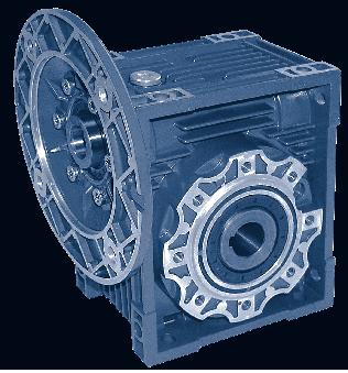
Versions. f.s. Worm gear units CMRV CMRV-CMRV... PC-CMRV... CRV CRV-CMRV...
|
|
|
- Chrystal Nichols
- 6 years ago
- Views:
Transcription


1 Worm Gear Units 313

 TYPE OF LOAD: A - uniform fa 0.")
 moment of reduced external inertia at the drive-shaft Jm (kgm2) moment of inertia of motor")


2 Versions CMRV The service factor (f.s.) depends on the operating conditions the reduction unit is subjected to. The parameters that need to be taken into consideration to select the most adequate service factor correctly comprise: type of load of the operated machine : A - B - C length of daily operating time: hours/day ( ) start-up frequency: starts/hour (*) TYPE OF LOAD: A - uniform fa 0.3 B - moderate shocks fa 3 C - heavy shocks fa 10 CMRV-CMRV... PC-CMRV... fa = Je/Jm Je (kgm2) moment of reduced external inertia at the drive-shaft Jm (kgm2) moment of inertia of motor If fa > 10 call our Technical Service. A - Screw feeders for light materials, fans, assembly lines, conveyor belts for light materials, small mixers, lifts, cleaning machines, fillers, control machines. B - Winding devices, woodworking machine feeders, goods lifts, balancers, threading machines, medium mixers, conveyor belts for heavy materials, winches, sliding doors, fertilizer scrapers, packing machines, concrete mixers, crane mechanisms, milling cutters, folding machines, gear pumps. C - Mixers for heavy materials, shears, presses, centrifuges, rotating supports, winches and lifts for heavy materials, grinding lathes, stone mills, bucket elevators, drilling machines, hammer mills, cam presses, folding machines, turntables, tumbling barrels, vibrators, shredders. CRV f.s. CRV-CMRV


3 Direction of Rotation The helix is right-handed Critical Applications The performance given in the catalogue correspond to mounting position B3 or similar, ie. when the first stage is not entirely immersed in oil. For other mounting positions and/or particular input speeds, refer to the tables that highlight different critical situations for each size of reduction unit. It is also necessary to take due consideration of and carefully assess the following applications by calling our Technical Service: As a speed increasing. Use in services that could be hazardous for people if the reduction unit fails. Applications with especially high inertia. Use as a lifting winch. Applications with high dynamic strain on the case of the reduction unit. In places with T under -5 C or over 40 C. Use in chemically aggressive environments. Use in a salty environment. Mounting positions not envisaged in the catalogue. Use in radioactive environments. Use in environments pressures other than atmospheric pressure. Avoid applications where even partial immersion of the reduction unit is required. The maximum torque (*) that the gear reducer can support must not exceed two times the nominal torque (f.s.=1) stated in the performance tables. (*) intended for momentary overloads due to starting at full load, braking, shocks or other causes, particularly those that are dynamic. CRMV V5: 1500 < n1 < B B B B B n1 > 3000 B B B B B A A A A A V6 B B B B B B B B B B A = Application not recomended B = Check the application or call technical department 315
4 Installation and Lubrication To install the reduction unit it is necessary to note the following recommendations: The mounting on the machine must be stable to avoid any vibration. Check the correct direction of rotation of the reduction unit output shaft before fitting the unit to the machine. In the case of particularly lengthy periods of storage (4/6 months), if the oil seal is not immersed in the lubricant inside the unit, it is recommended to change it since the rubber could stick to the shaft or may even have lost the elasticity it needs to function properly. Whenever possible, protect the reduction unit against solar radiation and bad weather. Ensure the motor cools correctly by assuring good passage of air from the fan side. In the case of ambient temperatures < -5 C or > +40 C call the Technical Service. The various parts (pulleys, gear wheels, couplings, shafts, etc.) must be mounted on the solid or hollow shafts using special threaded holes or other systems that anyhow ensure correct operation without risking damage to the bearings or external parts of the units. Lubricate the surfaces in contact to avoid seizure or oxidation. Painting must definitely not go over rubber parts and the holes on the breather plugs, if any. For units equipped with oil plugs, replace the closed plug used for shipping with the special breather plug. Check the correct level of the lubricant through the indicator, if there is one. Starting must take place gradually, without immediately applying the maximum load. When there are parts, objects or materials under the motor drive that can be damaged by even limited spillage of oil, special protection should be fitted. The reduction units size are supplied complete with lubricant for life, synthetic oil, and can therefore be mounted in any position envisaged in the catalogue. The only exceptions are CMRV090- and CRV in position. V5/V6 for which you should call our Technical Service to assess the conditions of use. The reduction units size 110, 130 and 150 are supplied complete with lubricant, mineral oil. For sizes 110, 130 and 150 it is necessary to specify the position, otherwise the reduction units are supplied with the quantity of oil relating to position B3, (breather supplied). Only reduction units 110, 130 and 150 are fitted with breather, level and oil drainage plugs. It is necessary, after installation, to replace the closed plug used for transportation with the breather plug supplied with the unit. The pre-stage helical modules are supplied complete with lifelong lubricant, synthetic oil and can therefore be mounted in all the positions. Lubrication is separated from that of the worm reduction unit. Lubrication In cases of ambient temperatures not envisaged in the table, call our Technical Service. In the case of temperatures under -30 C or over 60 C it is necessary to use oil seals with special properties. For operating ranges with temperatures under 0 C it is necessary to consider the following: 1- The motors need to be suitable for operation at the envisaged ambient temperature. 2- The power of the electric motor needs to be adequate for exceeding the higher starting torques required. 3- In the case of reduction units with a cast-iron case, pay attention to impact loads since cast iron may have problems of fragility at temperatures under -15 C. 4- During the early stages of service, problems of lubrication may arise due to the high level of viscosity taken on by the oil and so it is wise to have a few minutes of rotation under no load. The oil needs to be changed after approximately 10,000 hours. This period depends on the type of service and the environment where the reduction unit works. T 0 C - ISO... AGIP SHELL ESSO MOBIL CASTROL BP CMRV PC (synthetic oil) -25) - (+50) ISO VG320 Telium VSF320 Tivela oil S320 S220 Glygoyle 30 Alphasyn PG32 Energol SG-XP320 CMRV (mineral oil) -5) - (+40) ISO VG460-15) - (+25) ISO VG220 Blasia 460 Blasia 220 Omala oil 460 Omala oil 220 Spartan EP460 Spartan EP220 Mobilgear 634 Mobilgear 630 Alphamax 460 Alphamax 220 Energol GR-XP460 Energol GR-XP220 CMRV PC B B B6-B V V
5 Radial Loads Fr Frx Fa L2 L CRMV a b Fr2 max x Frx Fr L2 L CRMV a b 76 94, Fr2 max The radial load on the shaft is calculated with the following formula: Fre (N) M D Resulting radial load (Nm) Torque on the shaft (mm) Diameter of the transmission member mounted on the shaft Fr (N) Value of the maximum permitted radial load (see relative tables) fz = 1.1 gear pinion 1.4 chain wheel 1.7 v-pulley 2.5 flat pulley When the resulting radial load is not applied on the centre line of the shaft it is necessary to calculate the effective load with the following formula: a, b, x = (see relative tables) Fre = 2000 x M x fz D < Fr1 to Fr2 Fre < Fr x a (b + x) < Fr1max to Fr2max 317

6 Possible Motor Flanges P M N D CMRV PAM D N M P IEC 5 7, B B B B B B B B B B B B B B B B B B B B B /112B /112B B B B B B /112B /112B B B B B B * 38* 38* 38* /112B B B B * 38* 38* 38* 38* 38* 38* /112B B B B /112B * Low profile key supplied by Challenge 318

7 PC & CMRV Combinations PC 063 PC 071 PC 080 PC 090.CMRV i 105 / 11 i = / 14 i = / 14 i = / 19 i = / 19 i = / 24 i = / 28 i = / 19 i = 2, / 24 i = 2, / 28 i = 2, PC B5-140 /11 P1 P (P) PC B5-160 / / 14 (120 / 19) PC B5-200 / / 14 PC B5-200 / / 24 (..) Only on request (160 / 24) (160 / 28) (160 / 19) (160 / 128) 319
8 Efficiency Efficiency Efficiency is a parameter which has a major influence on the sizing of certain applications, and basically depends on gear pair design elements. The mesh data table on page 321 shows dynamic efficiency (n1=1400 rev/min) and static efficiency values. Remember that these values are only achieved after the unit has been run in. Dynamic Irreversibility Dynamic irreversibility is achieved when the output shaft stops instantly when drive is no longer transmitted through the worm shaft. This condition requires a dynamic efficiency of nd < 0.5. Static Irreversibility Static irreversibility is achieved when, with the gear reducer at a standstill, the application of a load to the output shaft does not set in motion the worm shaft. This condition requires a static efficiency of ns < 0.5. The table shows approximate irreversibility classes. Vibrations and shocks can affect a gear reducer s irreversibility. For the irreversibility conditions of a combined geared unit one must consider that the efficiency of the group is given by the product of the efficiencies of each single reducer, i.e.: ntot = n1xn2 nd DYNAMIC IRREVERSIBILITY ns STATIC IRREVERSIBILITY > 0.6 Dynamic reversibility > 0.55 Static reversibility 0.5 to 0.6 Low dynamic reversibility 0.5 to 0.55 Low static reversibility 0.4 to 0.5 Good dynamic irreversibility < 0.5 Static irreversibility < 0.4 Dynamic irreversibility 320
9 Mesh Data RV i=ratio Z y 25 03' 19 19' 13 09' 10 41' 6 40' 5 23' 4 31' 3 53' Mx 1,3 1,3 1,3 0,995 1,3 0,995 0,8 0,67 nd(1400) 0,85 0,83 0,79 0,75 0,67 0,62 0,58 0,55 ns 0,71 0,68 0,61 0,56 0,46 0,41 0,36 0,34 Z y 18 49' 14 20' 9 40' 7 42' 5 35' 4 52' 3 52' 3 12' 2 45' 2 07' Mx 1,44 1,44 1,44 1,09 1,7 1,44 1,09) 0,89 0,74 0,56 nd(1400) 0,85 0,82 0,77 0,73 0,68 0,65 0,59 0,55 0,51 0,44 ns 0,67 0,63 0,55 0,5 0,43 0,39 0,35 0,31 0,27 0,23 Z y 24 28' 18 51' 12 49' 10 23' 8 43' 6 29' 5 14' 4 23' 3 47' 2 57' 2 25' Mx 2,06 2,06 2,06 1,57 1,27 2,06 1,57 1,27 1,06 0,81 0,65 nd(1400) 0,87 0,85 0,82 0,78 0,75 0,7 0,65 0,62 0,58 0,52 0,47 ns 0,71 0,67 0,6 0,55 0,51 0,45 0,4 0,36 0,32 0,28 0,24 Z y 23 54' 18 23' 12 30' 10 06' 8 29' 6 19' 5 06' 4 16' 3 40' 2 52' 2 21' Mx 2,56 2,56 2,56 1,95 1,58 2,56 1,95 1,58 1,32 1 0,8 nd(1400) 0,88 0,86 0,82 0,79 0,76 0,72 0,67 0,63 0,59 0,53 0,49 ns 0,7 0,66 0,59 0,55 0,51 0,44 0,39 0,35 0,32 0,27 0,23 Z y 24 31' 18 53' 12 51' 10 25' 8 45' 6 30' 5 15' 4 24' 3 47' 2 58' 2 26' Mx 3,25 3,25 3,25 2,48 2 3,25 2,48 2 1,68 1,27 1,02 nd(1400) 0,88 0,87 0,83 0,81 0,78 0,74 0,7 0,66 0,62 0,57 0,51 ns 0,71 0,67 0,6 0,55 0,51 0,45 0,4 0,36 0,33 0,28 0,24 Z y 26 17' 20 20' 13 52' 11 18' 9 32' 7 02' 5 42' 4 48' 4 08' 3 14' 2 40' Mx 3,94 3,94 3,94 3 2,42 3, ,03 1, nd(1400) 0,89 0,88 0,85 0,82 0,80 0,76 0,72 0,69 0,65 0,60 0,55 ns 0,71 0,68 0,61 0,57 0,53 0,46 0,42 0,38 0,35 0,29 0,26 Z y 29 11' 22 44' 15 36' 12 50' 10 54' 7 57' 6 30' 5 30' 4 46' 3 45' 3 06' Mx 4,84 4,84 4,84 3,69 2,98 4,84 3,69 2,98 2,5 1,89 1,52 nd(1400) 0,9 0,89 0,86 0,84 0,82 0,78 0,75 0,72 0,69 0,63 0,59 ns 0,73 0,7 0,64 0,6 0,56 0,49 0,45 0,41 0,38 0,32 0,28 Z y 28 15' 21 57' 15 02' 14 41' 12 34' 7 39' 7 28' 6 22' 5 32' 4 24' 3 39' Mx 5,875 5,875 5,875 4,62 3,73 5,875 4,62 3,73 3,13 2,37 1,91 nd(1400) 0,9 0,89 0,86 0,85 0,84 0,79 0,78 0,75 0,72 0,67 0,63 ns 0,72 0,69 0,63 0,62 0,59 0,48 0,48 0,44 0,41 0,36 0,32 Z y 28 41' 22 19' 15 18' 13 52' 11 49' 7 47' 7 02' 5 58' 5 11' 4 07' 3 24' Mx 6,97 6,97 6,97 5,4 4,37 6,97 5,4 4,37 3,67 2,77 2,23 nd(1400) 0,91 0,89 0,87 0,86 0,84 0,8 0,78 0,75 0,72 0,68 0,64 ns 0,72 0,69 0,63 0,61 0,58 0,49 0,46 0,43 0,39 0,34 0,3 Z y 32 09' 24 35' 17 27' 12 53' 11 19' 9 50' 6 32' 5 43' 4 57' 3 55' 3 14' Mx 5,5 6,155 5,5 6, ,193 6, ,193 3,17 2,55 nd(1400) 0,91 0,9 0,88 0,86 0,84 0,83 0,78 0,76 0,73 0,68 0,64 ns 0,73 0,71 0,66 0,6 0,57 0,54 0,45 0,42 0,39 0,33 0,29 321
10 Materials and Design Features (PC) The PC construction is modular and therefore it can be supplied as a separate unit to be mounted on any type of fitted geared motor (PAM). In this connection, the various possibilities of flange/output shafts. Fitting the pre-stage helical module on the main reduction unit is easily done as for any motor of type B14. The pre-stage unit cannot be used by itself, but only coupled with another reduction unit. Materials Case in aluminium alloy. Gears in case hardened, hardened, tempered steel 20MnCr5 (UNI7846) accurately ground on the involute. Coupling to electric motor Correctly fitting the pinion on the electric motor shaft requires you keep to the following instructions: a) Thoroughly clean the electric motor shaft. b) Remove the motor key from its seat. c) Fit the bush (1) to the drive shaft as shown in the diagram. To make this easier, you can heat the bush to approximately 70/80 C. d) Fit the new key (3) provided in place of the one removed beforehand. e) Fit the pinion (4) taking the same precautions as described in point (c). f) Fit the washer (5) and tighten with the screw (6). g) Remove the rubber cap mounted on the seat of the oil seal, taking care since the pre-stage unit is already complete with lubricant. h) Fit the oil seal (2) and then the motor assembly, taking care not to damage the lip of the oil seal. N.B. For correct operation, with no vibration or noise, it is recommended to use good quality motors
11 Mounting Positions CMRV - CRV CMRV...U - B3 B6 V5 V6 B8 B7 PC - CMRV CMRV...U - B3 B6 V5 V6 B8 B7 U version is related to sizes from CMRV and CRV For these sizes it is not necessary to specify mounting position. Unless specified otherwise, the standard positions are B3. For positions not envisaged, it is necessary to our Technical Service. technicalsupport@challengeproduction.com 323
12 Execution of Double Reduction CMRV-CMRV / CRV-CMRV AS1 AS2 VS1 VS PS1 PS2 BS1 BS The position of the 1st reducer with respect to the 2nd gear reducer depend on the version. Unless otherwise specified at the time of order, combination groups are supplied in version BS2. The specified mounting position refers to the 2nd gear reducer. D Flange F S Unless specified otherwise, the reduction unit is supplied with the flange in pos. D referred to position B3. In the case of specific requirements, when ordering, specify the position of the terminal box as shown in the diagram
13 CMRV Performance input n1 = 1400 rev/min i output n2 = rev/min Size P1 (kw) Geared Motors Motor Frame M2 (Nm) f.s B Size Gear Units B CMRV025 CRV B M2 (Nm) Fr1 (N) Fr2 (N) B B B A A C C C C B CMRV030 CRV B A A B A C C C B B CMRV B CRV A C B A A C C C B A CMRV A CRV B B B A B
14 CMRV Performance input n1 = 1400 rev/min i output n2 = rev/min Size P1 (kw) Geared Motors Motor Frame M2 (Nm) f.s LL Size Gear Units CMRV S CRV M2 (Nm) Fr1 (N) Fr2 (N) LL LL LL S C A A B B M M L LL LL CMRV LL CRV S C C A A MS MS MS M LB CMRV LB CRV LL LL LL C B
15 CMRV Performance input n1 = 1400 rev/min i output n2 = rev/min Size P1 (kw) Geared Motors Motor Frame M2 (Nm) f.s M Size Gear Units CMRV M CRV M2 (Nm) Fr1 (N) Fr2 (N) L L S MS LB LB LA L S M M M M M CMRV L CRV L MS M LB LL L L L L M CMRV M CRV M S S M LB
16 PC-CMRV Performance IM B34A input n = 1400 rev/min i output n2 = rev/min Size P1 (kw) Geared Motors Motor Frame B PC063+CMRV A M2 (Nm) f.s. Fr2 (N) B B A A C C C PC063+CMRV B B B A C C PC063+CMRV C B B A A PC071+CMRV A A A C B PC071+CMRV B A A A C C C PC071+CMRV B B A A C C PC071+CMRV C B B
17 PC-CMRV Performance input n1 = 1400 rev/min i output n2 = rev/min Size P1 (kw) Geared Motors Motor Frame PC080+CMRV A M2 (Nm) f.s. Fr2 (N) C C A A C C PC080+CMRV C C B C C C PC080+CMRV C B A C C C PC080+CMRV C C C C LL LL LL PC090+CMRV LL L S S LL LL LL PC090+CMRV LL LL L S
18 CMRV-CMRV Performance input n1 = 1400 rev/min i output n2 = rev/min Size Geared Motors P1 (kw) Motor Frame M2 (Nm) f.s. Size Gear Units M2 (Nm) B B B B B B B CMRV025/ B B B B B B B B A A A A A A CMRV025/ A A A A A A A B CMRV030/ A CRV030/ Fr1 (N) Fr2 (N) A A A A A A A A A A A
19 CMRV-CMRV Performance input n1 = 1400 rev/min i output n2 = rev/min Size Geared Motors P1 (kw) Motor Frame M2 (Nm) f.s A Size Gear Units CMRV030/ A CRV030/ M2 (Nm) Fr1 (N) Fr2 (N) A A B B B A A A A A A C C B A A B CMRV030/ B CRV030/ B A A A A A B B A B B B CMRV040/ A CRV040/ B B B A A A
20 CMRV-CMRV Performance input n1 = 1400 rev/min i output n2 = rev/min Size Geared Motors P1 (kw) Motor Frame M2 (Nm) f.s B Size Gear Units CMRV040/ B CRV040/ M2 (Nm) Fr1 (N) Fr2 (N) B B B A A B A A B B A C C A A A B CMRV050/ B CRV050/ A A B A A A L L S B B B CMRV063/ A CRV063/ B B A A A A
21 CMRV-CMRV Performance input n1 = 1400 rev/min i output n2 = rev/min Size Geared Motors P1 (kw) Motor Frame M2 (Nm) f.s LL Size Gear Units CRV063/ S CRV063/ M2 (Nm) Fr1 (N) Fr2 (N) LL LL LL LL LL L C C A A B A A Weight without motor 0.7 kg For the dimensions concerning the motor connection area (Pm, Dm, bm, tm) please refer to the table shown at page
22 Dimensions A B D D G G G H I K KE M6*11 (4) M6*10 (4) M8*10 (4) M8*14(8) M8*14(8) M10*18(8) M10*18(8) M12*21(8) M12*21(8) L M N N O P Q R S T V W b (10) t (21.8) 28.3 (27.3) 28.3 (31.3) 31.3 (38.3) 38.3 (41.3) b t f - - M6 M6 M8 M8 M10 M10 M12 kg kg = Weight without motor For the dimensions concerning the motor connection area (Pm, Dm, bm, tm) please refer to the table shown at page
23 Dimensions of Output Flanges Flange KA KB KC KN F KM min 90 min KO 6.5 x 4 9 x 4 11 x 4 11 x 4 14 x 4 14 x 4 14 x 8 16 x 8 16 x 8 KP KQ KW KA KB KC KN FL KM - 80 min 90 min KO - 9 x 4 11 x 4 11 x 4 14 x 4 14 x 4 14 x KP KQ KW KA KB KC FB KN KM KO x x 4 11 x 4-11 x KP KW
24 PC & CMRV Dimensions PC063+CMRV PC071+CMRV PC80 / PC090+CMRV A E G G G H I I L L K KE M6*10(4) M8*10(4) M8*14(8) M8*10(4) M8*14(8) M8*14(8) M10*18(8) M8*14(8) M10*18(8) M10*18(8) M12*21(8) M N N O P Q R S T V W D b t kg kg = Weight without motor For the dimensions of the output flanges, please consider the drawing of relevant CMRV size. For the dimensions of the hollow shafts in option, please consider the drawing of relevant CMRV size. For the dimensions of the double extention worm shafts, please consider the drawing of relevant CMRV size. 336
25 CMRV & CMRV Dimensions CMRV-CMRV A B G H I R H I N R Z kg kg = Weight without motor 337
26 CRV & CRV-CMRV Dimensions CRV CRV B D1 9 j6 11 j6 14 j6 19 j6 24 j6 24 j6 28 j6 30 j6 35 j6 G G I b f1 - - M6 M6 M8 M8 M10 M10 M12 t1 10,2 12, , CRV-CMRV CRV-CMRV B D1 9 j6 9 j6 9 j6 11 j6 11 j6 14 j6 19 j6 19 j6 G I b f M6 M6 M6 t1 10,2 10,2 10,2 12,5 12, ,5 21,5 For the missing dimensions, please consult the CMRV size drawing. 338
27 Output Shafts & CTA Torque Arms COS-S Single COS-D Double Size d B B1 G1 L L1 f b1 t g6 (9) 23 (25) 25,5 (30) (85,5) h , M h M6 6 20, h , M h , M h , M h , M h , M h M , h M ,5 4 ( 3 ) 12,5 (10,2) CTA Torque arms Size K1 G Kg KH R , , , , ,
28 Motor Input Flanges PAM B5 & PAM B14 PAM B5 Dimensions IEC B Pm Dm bm tm 10,4 12,8 16,3 21,8 27,3 31,3 31,3 41,3 45,3 51,8 59,3 PAM B14 Dimensions IEC B Pm Dm bm tm 10,4 12,8 16,3 21,8 27,3 31,3 31,3 41,3 340
29 Cover & Shaft Sleeves Cover TYPE C CMS Reduction bushing kit SINGLE SIZE SHAFT SLEEVES TYPE øi/øe L KEY Weight kg CMS 9/ /3 x 4 x CMS 11/ /4 x 6 x CMS 14/ x 5 x CMS 19/ x 5.5 x 20 8 x 5.5 x CMS 24/ x 9 x CMS 28/ x 7 x CMS 38/ /10 x 10 x DOUBLE SIZE SHAFT SLEEVES TYPE øi/øe L KEY Weight kg CMS 9/ x 6 x CMS 11/ x 7 x CMS 19/ x 7 x CMS 24/ x 8 x
30 Drive Design Drive design Example: To design a drive a few simple questions need to be asked, then calculated first. For example, a belt conveyor needs to be driven by a shaft mounted worm gear unit. Belt speed required: say for example 55 feet per minute Diameter of drive roller/drum: say for example 1 foot Calculation for the output speed the gear unit needs to run at, or the drum speed needs to be, is as follows: Diameter of drum in feet, multiplied by (pi) multiplied by the speed in rev/min, gives you the feet per min / Belt speed, So, 1 x x 17.5 rev/min = ft per min say 55 feet per min. Our gear unit output speed needs to be 17.5 rev/min If we assume our motor input speed is 1400 rev/min divided by 17.5 rev/min, gives you 80, so the ratio of the gear unit is 80:1. Now we need to calculate the power required: To do this we need to calculate the torque in Newton meters (Nm), the calculation is as follows: Load in lbs multiplied by the radius of the roller/drum gives you the torque required to lift the load vertically. By exerting a pull around a drum or pulley see Fig 1 Fig 1 So the lifting torque is 3416Nm x 0.05 = 170.8Nm coefficient of friction or rolling friction for this type of application. We now have a required torque of 170.8Nm. What we need to do now is apply a service factor. Service factors can vary considerably depending on the application. Example: Conveyors running 16 hours per day with up to 10 stops and starts per hour would be a service factor of 1.3, therfore we take the required torque of 170.8Nm multiplied by the 1.3 service factor = Nm say 222Nm this is called the design power. We can now look in the catalogue and find a gear unit with a rated torque of 222Nm or slightly larger with a service factor (f/s) of 1 or more. The unit we require is a CMRV090 80:1 the catalogue shows this unit rated at.92kw At 316Nm torque. Now we take.92kw divided by 316Nm and multiply by 222Nm = 0.646kW. 0.92kW and 0.646kW motors are none standard so we need to choose a 0.75kW 4 pole 1400rev/min motor in a 80B5 output flange and a CMRV090 80:1 B5 80 input flange. the actual torque we will get from our selection is 257Nm which will now give a service factor of 1.5. Useful formulae: Feet per minute = kw to torque Nm = kw x 9550 rpm Coefficient of friction: diameter of drum/roller x ft x rev/min Coefficient of friction varies from application to application, but a general rule for anti friction bearings is 0.01 to 0.05, for example, a chain conveyor on a 5 Incline would use a coefficient of friction equal to 0.05, inclines over 45 should be treated as a straight lift. The load including the belt is 2.25 tons. So, 2240lbs = 1 ton x 2.25 = 5040 lbs/2.25tons x 0.5ft radius of roller/drum =2520lbs ft torque to convert to Nm x = 3416Nm Now we have to apply a coefficient of friction or rolling friction, Effectively we will lay the lifting torque in Fig 1 flat, as if rotating the illustration 90 degrees clockwise. 342
31 Useful Conversion Data To convert Multiply by Force lbf to N kgf to N Mass oz to grams lb to kg tons to tonnes (1000kg) tons to short (US) tons 1.12 Powers horsepower to kw hp to metric hp metric hp to kw Pressures lb/sq in to kg/sq cm lb/sq ft to kg/sq m 4.88 lb/sq in to ft of water 2.31 lb/sq in to atmospheres Speeds ft/sec to m/sec ft/sec to knots ft/sec to miles/hr ft/min to m/sec knots to miles/hr miles/hr to km/hr knots to km/hr Torque lbf ft to Nm kgf m to Nm lbf ft to kgf m Volumes cu in to cu cm cu ft to cu m cu ft to galls 6.25 cu ft to litres pints to litres To convert Multiply by Volumes cont.. galls to litres Imp galls to US galls 1.2 US barrels to cu m 0.16 N to lbf Ntokgf grams to oz kg to lb tonnes to tons (22401bs) short (US) tons to tons kwtohp metric hp to hp kw to metric hp kg/sq cm to lb/sq in kg/sq m to lb/sq ft ft of water to lb/sq in atmospheres to lb/sq in 14.7 m/sec to ft/sec knots toft/sec miles/hr to ft/sec m/sec to ft/min miles/hr to knots km/hr to miles/hr km/hr to knots Nm to lbf ft Nm to kgfm kgfmtolbfft cu cm to cu in cu m to cu ft galls to cu ft 0.16 litres to cu ft litres to pints 1.76 litres to galls 0.22 US galls to Imp galls cu m to US barrels 6.29 The central columns of figures in bold type can be referred in either direction. To the left to convert metres into feet, or to the right to convert feet into metres. For example, five lines down: 5 feet = 1.52 metres, and 5 metres = feet. Feet Metres Feet Metres Feet Metres Feet Metres


32 344
Your Partner in Solutions 24/7. EMAW Worm Gearboxes. Tel: Fax: Web:
 Your Partner in Solutions 24/7 EMAW Worm Gearboxes Tel: 01902 601 403 Fax: 01902 601 408 Email: sales@emag-ltd.co.uk Web: www.emag-ltd.co.uk Worm Gear Units - Installation & Lubrication To install the
NMRV - MCV - NRV NMRV+NMRV PC+NMRV
 MAINTENANCE AND OPERATING INSTRUCTIONS FOR WORM GEAR REDUCERS AND GEARMOTORS SERIES: NMRV - MCV - NRV NMRV+NMRV PC+NMRV GB NMRV-UM-9 99/01 rev.15.07.99 2 Warehouse storage When moving the unit, care should
NMRV SERIES WORM-GEAR SPEED REDUCERS
 NMRV SERIES WORMGEAR SPEED REDUCERS TRASMITAL GEAR INDIA PVT LTD Brief introduction to wormgear speed reducer Trasmital NMRV series wormgear speed reducer is a newgeneration product developed by our company
HSERIES. Helical geared motors
 HSERIES Helical geared motors Design features Motovario products are supplied with the following surface treatment features: Die-cast aluminium alloy cases for gears Die-cast materials undergo the following
MAINTENANCE AND USE INSTRUCTIONS FOR WORM GEAR REDUCERS AND GEARMOTORS SERIES: SW - ISW - SW+SW ISW+SW
 MAINTENANCE AND USE INSTRUCTIONS FOR WORM GEAR REDUCERS AND GEARMOTORS SERIES: SW - ISW - SW+SW ISW+SW GB 2 Warehouse storage When moving the unit, care should be taken to protect external parts from breakage
 http://www.dongco.com/ Contents Service factor & Installation notice 2 Worm geared motors and worm gear units 4 Input flange Dimensions 6 Mesh data 7 NMRV NMRV Performance 8 http://www.dongco.com/ NRV
Section 9: Gearboxes: Series W
 GEARBOXES Section : 9 Section 9: Gearboxes: Series W A modular designed aluminium worm box available in a vast range of sizes and ratios for cost effective solutions. 9 s with ratings from 0.09 to 7.5kW
A p p l i c a t i o n s
 A p p l i c a t i o n s Service Factor The AGMA Classification of service factor depends on the conditions under which the gear reducer operates. Motovario reducers can be rated for operation using the
CHC SERIES HELICAL GEAR UNITS
 CHC SERIES HELICAL GEAR UNITS INTRODUCTION CHC series helical gear units is a new generation product, which designed basing on the modular system. It can be connected respectively with motors such as standard
GEAR BOXES AND MOTORS
 GEAR BOXES AND MOTORS page 5 page 25 page 56 page 58 page 88 page 121 page 136 page 141 page 153 60 YEARS OF HISTORY The goal pursued by Chiaravalli during more than 60 years of history is to become the
HYDRAULIC COMPONENTS HYDROSTATIC TRANSMISSIONS GEARBOXES - ACCESSORIES HT 14 / A / 103 / 0309 / E
 HYDRAULIC COMPONENTS HYDROSTATIC TRANSMISSIONS GEARBOXES - ACCESSORIES HT 14 / A / 103 / 0309 / E Pump Drives - Gearboxes Mechanical Dry Clutches Hydraulic Clutches Pump Adaptors CONTENTS Pump Drives AM
CHO HELICAL-HYPOID GEAR UNITS
 CHO HELICAL-HYPOID GEAR UNITS Kuželočelní převodovky INTRODUCTION CHO helical hypoid gear units have been conceived to be used instead of worm gearboxes where high efficiency is requested, especially with
Shaft Mounted Speed Reducer. Technical Catalogue
 Shaft Mounted Speed Reducer Technical Catalogue Where others fit, We perform Contents The Challenge SMSR stands tall amongst the crowd. Packed full of attention to detail, the Challenge SMSR delivers performance
SHAFT MOUNTED HELICAL GEAR REDUCER
 Shaft Mounted Helical Gear Assembly INTRODUCTION The VIGNESSH Shaft Mounted Helical Gear Units are the result of experience in design and production, taking advantage of the most recent relevent research
5 Gear units, types of installation, lubricant quantities. 5.1 Standard fitting positions/ types of installation for Bauer geared motors
 26 5 Gear units, types of installation, lubricant quantities 5.1 Standard fitting positions/ types of installation for Bauer geared motors 5 27 28 5.2 Position of the terminal box and the cable entry points
ENDURO BEVEL HELICAL GEARBOX
 ENDURO BEVEL HELICAL GEARBOX INDEX Technical characteristics pag. 2-3 List of components pag. 4-5 Performance table pag. 10-11 Code system pag. 6 Lubrication pag. 7 Performance table pag. 12 Dimensions
technology made in Italy
 technology made in Italy GB RD * * VS made in China Technology Made in Italy Since 1955 Varvel has been making speed reducers and variators for light industry applications. Reliable partner in power transmission
SERIES NEW PARALLEL HELICAL AND BEVEL HELICAL GEARBOXES PARALLEL HELICAL AND BEVEL HELICAL GEARBOXES
 SERIES NEW PARALLEL HELICAL AND BEVEL HELICAL GEARBOXES PARALLEL HELICAL AND BEVEL HELICAL GEARBOXES 1 2 SERIES 1 2 pag. pag. 5 Introduction Features 3 pag. pag. Versions Range and designation 5 pag. 9
Shaft Mounted Speed Reducers
 s Metric Range Features The Challenge SMSR stands tall amongst the crowd. Packed full of attention to detail, the Challenge SMSR delivers performance in the harshest of applications. Shaft mounted drives
SUDARSHAN GEARS ISO CERTIFIED COMPANY MADE IN INDIA ALUMINIUM WORM GEAR BOXES
 ALUMINIUM WORM GEAR BOXES Plot N. 7, Mira Co-op industrial Estate, National Highway No. 8, KashiMira Naka, Mira Road (E), Dist. Thane - 4004. India Tel.: 022 28455990/9/85 Fax No.: 022-28455982 Email:
Viking In-Line Helical Gear Reducers
 Page 615.1 Gear Ratio Range: (varies by reducer size) Output Speeds (with 1750 rpm input) Reducer Horsepower Range: From 2.63:1 to 38.0:1 (Varies by reducer size) 46 665 rpm.5 HP (.37 kw) to 350 HP (261
RS & RT WORM GEAR BOXES
 RS & RT WORM GEAR BOXES C-MRS-MRT ed0-2009 rev00 GB Product Description Multipurpose housing Aluminium die cast & Grey Iron Modular for all mountings Wormshaft ZI profile, hardened and ground. Alloy steel.
Power Jacks have taken time, engineering excellence and the best people to produce the ultra compact Neeter Drive gearbox.
 202 www.powerjacks.com Power Jacks have taken time, engineering excellence and the best people to produce the ultra compact Neeter Drive gearbox. Our expertise has been built on a history of engineering
not just a gear unit - every component manufactured with pride to exceed ISO 9000 standards by ISO 9000 certified manufacturer.
 powerdrive SMGU - the ORIGINAL and the BEST not just a gear unit - every component manufactured with pride to exceed ISO 9000 standards by ISO 9000 certified manufacturer. technidrive www.technidrive.com
BSERIES. Helical bevel geared motors
 BSERIES Helical bevel geared motors FAX-BACK-FORM 01924 409 513 as required Geared Motors on Fast Delivery Company : Contact : Tel : Email : Inline Helical Enquiry Ref : Please complete or Bevel Helical
Catalogue geared motors. Edition 01/
 Catalogue geared motors Edition 0/0 Page Gearboxes and Lubrication Standard fitting - BG and BF - BK and BS Position of the terminal box and the cabel entry - BG and BF - BK and BS Radial and axial forces
Bevel gearboxes. Catalogue
 Bevel gearboxes Catalogue INDEX Bevel gearbox description... page 2 Manufacturing features... page 2 Materials and components... page 4 Bevel gearbox selection... page 5 Thermal power limit... page 7
TECHNICAL CHARACTERISTICS
 GEARBOX WM 26 8 Nm TECHNICAL CHARACTERISTICS Worm gearbox. Life-time lubrication by grease, therefore it is main tenance-free. Housing. Die-casting aluminium. Worm-shaft. Hardened steel with grinding.
Helical Gear Motors BEGE Type G & M. Your drive, our (trans)mission. BEGE Power Transmission
mission. BEGE Power Transmission") Helical Gear Motors BEGE Type G & M BEGE Power Transmission Anton Philipsweg 30 2171 KX Sassenheim The Netherlands T: +31 252-220 220 E: bege@bege.nl W: www.bege.nl Your drive, our (trans)mission General
Helical Gear Motors BEGE Type G & M BEGE Power Transmission Anton Philipsweg 30 2171 KX Sassenheim The Netherlands T: +31 252-220 220 E: bege@bege.nl W: www.bege.nl Your drive, our (trans)mission General
EXAMPLES GEARS. page 1
 (EXAMPLES GEARS) EXAMPLES GEARS Example 1: Shilds p. 76 A 20 full depth spur pinion is to trans mit 1.25 kw at 850 rpm. The pinion has 18 teeth. Determine the Lewis bending stress if the module is 2 and
Lenze. Drives with worm gearboxes 52.
 6 887 Lenze Drives with worm gearboxes 5. Lenze Drive Systems GmbH, Postfach 0 5, D-76 Hameln, Site: Groß Berkel, Hans-Lenze-Straße, D-855 Aerzen, Phone ++9 (0) 55 8-0, Telefax ++9 (0) 55 8- E-Mail: Lenze@Lenze.de
 DEPARTMENT OF MECHANICAL ENGINEERING Subject code: ME6601 Subject Name: DESIGN OF TRANSMISSION SYSTEMS UNIT-I DESIGN OF TRANSMISSION SYSTEMS FOR FLEXIBLE ELEMENTS 1. What is the effect of centre distance
KINGS COLLEGE OF ENGINEERING DEPARTMENT OF MECHANICAL ENGINEERING
 KINGS COLLEGE OF ENGINEERING DEPARTMENT OF MECHANICAL ENGINEERING QUESTION BANK Sub Code/Name: ME 1352 DESIGN OF TRANSMISSION SYSTEMS Year/Sem: III / VI UNIT-I (Design of transmission systems for flexible
CHENDU COLLEGE OF ENGINEERING & TECHNOLOGY DEPARTMENT OF MECHANICAL ENGINEERING QUESTION BANK
 CHENDU COLLEGE OF ENGINEERING & TECHNOLOGY DEPARTMENT OF MECHANICAL ENGINEERING QUESTION BANK Sub Code: ME 2342 DESIGN OF TRANSMISSION SYSTEM UNIT - I 1. How the bevel gears are classified? Explain with
Viking s helical gear reducers are available in three basic sizes, each size offering several gear ratios.
 PARTS & ACCESSORIES: SIZES A, B & C Section 610 Page 610.1 Issue L Gear Ratio Range: (varies by reducer size) 1.87:1 to 7.95:1 Output Speeds (with 1750 rpm input) 950 to 220 rpm Reducer Horsepower Range:
CUT CAM TOOL CHANGERS CUT31 - CUT41 - CUT51
 CAM S 31-41 - 51 Smooth quiet motion Complete mechanical synchronization of cycle Both vertical and horizontal axis mounting position Positive control of acceleration and speed during full cycle Long life
Series J Shaft Mounted Gearbox
 Series J Shaft Mounted Gearbox Technical Up to - 600kW / 57,000 Nm Industrial Gearbox CJ-2.00GBA1211 PRODUCTS IN THE RANGE Serving an entire spectrum of mechanical drive applications from food, energy,
The product information and specifications within this catalogue should be viewed as a guide only and are subject to change without notice.
 Wheel gears... 3 Axial piston pumps... 3 Axial piston motors... 3 Winches... 4 Radial piston pumps... 4 Radial piston motors... 4 Slewing rings... 5 Gear pumps... 5 Gear flow dividers... 5 Cylinders...
FEATURES / BENEFITS... 2 SPECIFICATION / HOW TO ORDER... 4 NOMENCLATURE... 11
 CONTENTS QUANTIS RHB FEATURES / BENEFITS.................................... 2 SPECIFICATION / HOW TO ORDER........................... 4 NOMENCLATURE......................................... 11 GEARMOTORS
POLY V TAPER-LOCK PULLEYS
 POLY V TAPER-LOCK PULLEYS Types Grooved pulleys designed for industrial transmissions are identified by reference to the dimensions and the groove pitch in the following types: PPV-J PPV-L Profile dimensions
Vertical Linear Drive with Toothed Belt and Integrated Recirculating Ball Bearing Guide Series OSP-E..BV
 Vertical Linear Drive with and Integrated Recirculating Ball Bearing Guide Series OSP-E..BV Contents Description Page Overview 25-28 Technical Data 29-31 Dimensions 32-33 25 Parker Hannifin Corporation
INSTRUCTIONS FOR USE FACE GEARBOXES
 INSTRUCTIONS FOR USE FACE GEARBOXES TNC MTC-TC KTM ES Declaration of Conformity Producer: TOS ZNOJMO, akciová společnost Družstevní 3 CZ 669 02 Znojmo Equipment: Face gearboxes Type/ Modification:MTC,
 www.motiontech.com.au Copyright SERVOMECH This catalogue contents are under publisher copyright and may not be reproduced unless permission is agreed. Every care has been taken to ensure the accuracy of
Sheet 1 Variable loading
 Sheet 1 Variable loading 1. Estimate S e for the following materials: a. AISI 1020 CD steel. b. AISI 1080 HR steel. c. 2024 T3 aluminum. d. AISI 4340 steel heat-treated to a tensile strength of 1700 MPa.
Vertical Linear Drive with Toothed Belt and Integrated Recirculating Ball Bearing Guide Series OSP-E..BV
 Vertical Linear Drive with Toothed Belt and Integrated Recirculating Ball Bearing Guide Series OSP-E..BV Contents Description Page Overview 25-28 Technical Data 29-33 Dimensions 34 Order Instructions 35
INVOLUTE TOOLING CORPORATION
 MANUFACTURERS OF DRIVES AND TRANSMISSIONS OFFICE: 13, JORBAGH, NEW DELHI - 110 003, INDIA, TEL: +91(011)24621453 FAX: +91(011) 24603609 WORKS: PLOT-65, SEC-27C, FARIDABAD - 121 003. INDIA, TEL: +91(0129)
Operating Instructions
 Operating Instructions Table of contents Table of contents... 1 1. Declaration... 1 2. Warranty and liability... 2 3. Gear description... 2 4. Gear types... 2 5. Safety... 3 5.1 General safety information...
technology made in Italy RS RT
 technology made in Italy RS RT * * VS made in China Technology Made in Italy Since 1955 Varvel has been making speed reducers and variators for light industry applications. Reliable partner in power transmission
Section 9: Gearboxes: Series F
 GEARBOXES Section 9: Gearboxes: Series F The new Fenner Series F geared motor range is primarily designed as a compact shaft mounted unit incorporating an integral torque reaction bracket. ew range now
KAVITSU Excellence in Gear Technology. The compact And Efficient
 KAVITSU Excellence in Gear Technology The compact And Efficient OUR RANGE OF PRODUCT PLANETARY SPEED REDUCER TORQUE :- 0 Nm TO 50 00 000 Nm :- : TO 00000 : POWER :- 0.8 KW TO 000 KW MOUNTING :- FOOT, FLANGE,
GEAR-COUPLINGS. Series LX GLX S-NX
 GEAR-COUPLINGS Series LX GLX S-NX CONTENTS Application 3 Quality and production 3 Design and characteristics 3 selection 4-5 Key connections 6 Shrink-fit connections 7 Standard design with one-piece housing
Vertical Linear Drive with Toothed Belt and Integrated Recirculating Ball Bearing Guide Series OSP-E..BV
 Vertical Linear Drive with and Integrated Recirculating Ball Bearing Guide Series OSP-E..BV Overview...25-28 Technical Data...29-31 Dimensions...32-33 25 Features TOOTHED BELT DRIVE FOR VERTICAL MOVEMENTS
chain sprocket SIMPLEX DUPLEX TRIPLEX
 chain sprocket SIMPLEX DUPLEX TRIPLEX CHAIN SPROCKET DRIVE The Transmission of mechanical power without slippage and with a high degree of maintained efficiency is a basic function of the Roller Chain
Series BS Compact Worm Gear
 Series BS Compact Worm Gear Technical Up to - 4kW / 315 Nm Worm Gearbox CBS-2.00GB1211 PRODUCTS IN THE RANGE Serving an entire spectrum of mechanical drive applications from food, energy, mining and metal;
Viking Helical Gear Reducers
 Page 610.1 Issue J Gear Ratio Range: (varies by reducer size) 1.87:1 to 7.95:1 Output Speeds (with 1750 rpm input) Reducer Horsepower Range: 950 to 220 rpm 1.4 HP (.1 kw) to 49.8 HP (37.2 kw) THREE SIZES
KEB Gear units & Motors 2014
 Introduction KEB Gear units & Motors 2014 Contents Introduction 2 designation... 2 Product description... 3 Assembly / Disassembly notes when using gear units with hollow shaft... 5 Drive selection...
Vane Air Motors - P1V-B
 Vane Air Motors - P1V-B These large motors are designed for use in the most arduous applications, requiring considerable power, torque, robustness and reliability Operating information Working pressure:
CERTIFIED MANAGEMENT SYSTEM
 EN RS RT CERTIFIED Technology Made in Italy Since 955 Varvel has been making speed reducers and variators for light industry applications. Reliable partner in power transmission equipment offers also customized
24 Sizes of entire steel coupling from to Nm.
 Fasteners class 12.9 allow torque transmission by adhesion. Special gear teeth realized in order to increase the contact surface and to limit the superficial pressure. Tightness with standard o-rings that
Speed Reducers and Gearmotors
 ofc BEVEL BUDDYBOX Speed Reducers and earmotors CATALO 13.605.50.001 Bevel Buddybox Rugged Spiral Bevel Output Modular Cyclo Input Compact Size Two-Year Warranty Eccentric Cam and Roller Assembly Housing
Certified Quality System UNI EN ISO 9001 : 2008 SERVICE MANUAL PGRF series Release A10/14
 312 Certified Quality System UNI EN ISO 9001 : 2008 www.comerindustries.com SERVICE MANUAL PGRF series Release A10/14 INDEX GENERAL INFORMATION... 3 GEARBOX UNIT IDENTIFICATION... 3 RISKS AND PRECAUTIONS...
B G SPIRAL BEVEL GEARBOXES BG SPIRAL BEVEL GEARBOXES
 BG 1 SPECIFICATION GENERAL Spiral bevel gearboxes BG incorporate the most modern advances in bevel gearbox design and construction. These gearboxes offer an extensive range of ratios together with an excellent
Technical Information
 CYCLO 6 5 Technical Information Technical Information Technical Information 5.1 CYCLO 6 Lubrication Cyclo are either Grease lubricated or Oil lubricated. Refer to pages 5.3 and 5.4 to determine the unit
KS TWINGEAR. Compact, precise and powerful.
 MS-Graessner GmbH & Co. KG THE GEAR COMPANY Compact, precise and powerful Precision combines with performance. Bevel gear technology is at the heart of an assembly consisting of gear housing, shafts, flanges
DOCUMENTATION - INSTALLATION _ MAINTENANCE
 Bevel gears DOKUMENTATION BETRIEBS_ UND WARTUNGSANLEITUNG DOCUMENTATION - INSTALLATION _ MAINTENANCE FOR BEVEL GEARS 1 Bevel gears Radial forces Permissible radial load (stress) on input (d 1 ) and output
Fig. 1 Two stage helical gearbox
 Lecture 17 DESIGN OF GEARBOX Contents 1. Commercial gearboxes 2. Gearbox design. COMMERICAL GEARBOX DESIGN Fig. 1 Two stage helical gearbox Fig. 2. A single stage bevel gearbox Fig. 4 Worm gearbox HELICAL
CYLINDRICAL CAM INDEXING ROTARY TABLES IR TABLES HEAVY SERIES IR IR IR 2001 COLOMBO FILIPPETTI SPA
 CYLINDRICAL CAM INDEXING IR HEAVY SERIES COLOMBO FILIPPETTI SPA Sealed electrowelding gear housing. Indexing output plate with fixed central through hole. Input shaft and worm screw on opposite taper roller
Helical and Bevel Gearboxes
 Kumera Power-Plaza is the online market place for Kumera mechanical transmission products and associated spare parts. Power-plaza.com speeds up the process of requesting for quotations. www.power-plaza.com
Roller chains TPM - QRC pag. 40 Roller chains RCX pag. 43 Conveyor chains CRT pag. 45 Chain guide rails in polyethylene pag. 48
 INDEX Sprockets - Platewheels pag. 2 Asa sprockets - platewheels pag. 20 Duplex platewheels for two simple chains pag. 26 Stainless steel sprockets - Aisi 304 L - Simplex sprockets hardened teeth pag.
POWER GEAR The high performance bevel gearbox
 MS-Graessner GmbH & Co. KG THE GEAR COMPANY The high performance bevel gearbox Precision combines with performance. Bevel gear technology is at the heart of an assembly consisting of gear housing, shafts,
Section 9: Gearboxes: Series K
 GEARBOXES Section : 9 Section 9: Gearboxes: Series K The Fenner Series K incorporates all the core design features in a highly efficient yet flexible bevel helical drive. Drives up to 90 Highly efficient
PARALLEL INDEX DRIVES TP Series
 PARALLEL INDEX DRIVES TP Series Calculations J = moment of inertia Application examples Direct driven belt/chain = M B + M B M B = c a n 2π n x t² M R = µ g R m = M B + M R + (M ST )* M ST = m g R M AN
Quatro+ Series. Proven planetary gearing for challenging applications
 Cement Chemicals Defence Fibre, paper & tissue Food & beverage Marine & port operations Metals Mining & minerals Oil & gas Panelboard Power generation Rail Rubber Sugar Water & wastewater Quatro+ Series
Stromag Dessau. safety in motion PRODUCT CATALOGUE. NFF4F-LS Brake. for Slow-Running High Torque Drivelines, in harsh environment
 Stromag Dessau safety in motion PRODUCT CATALOGUE NFF4F-LS Brake for Slow-Running High Torque Drivelines, in harsh environment ENGINEERING THAT MOVES THE WORLD Applications Holding brake variations with
External gear pump Series G
 External gear pump Series G RE 10 093/04.14 Replace RE 10 093/06.13 AZPG-22 Fixed pumps V = 22.5...100 cm 3 / rev Overview of contents Contents Page General 2 Product overview 3 Ordering code single pumps
GEARED TO EXCEL SMSR GEAR BOX PLUMMER BLOCK HELICAL GEAR PUMP V BELT PULLEY
 www.nisukaindustries.com GEARED TO EXCEL SMSR GEAR BOX PLUMMER BLOCK HELICAL GEAR PUMP V BELT PULLEY COMPANY PROFILE The Industries Private Limited was established in 994 for manufacturing High Quality
314 ORDINARY MAINTENANCE MANUAL FOR. PGA series VERTICAL MOUNTING POSITION. Release A02/15
 314 www.comerindustries.com ORDINARY MAINTENANCE MANUAL FOR PGA series VERTICAL MOUNTING POSITION Release A02/15 INDEX General information...page 3 Ordinary maintenance...page 4 Oil lubricant replacement...page
Planning Section. Environmental conditions. Different power supply. Industrial solutions
 Planning Section 86 89 Environmental conditions Different power supply 90 Industrial solutions 91 Power calculation and selection of the Motorized Pulley for package transportation 93 Oil types and contents
GHE-Series Single Screw Extruder Units
 GHE-Series Single Screw Extruder Units Contents General Description 1 Design Feature.. 2 Selection Procedure 3 Thrust Bearing Data 4 Thrust Bearing Life. 5 Mechanical Capacity 9 Output Torque and Exact
RS & RT WORM GEAR BOXES
 RS & RT WORM GEAR BOXES Product description Multipurpose mounting Aluminium die cast and Cast iron (from size 0 up) Wormshafts ZI profile, Hardened and ground. Alloy steel. RS Input IEC and NEMA motor
Shaft Mounted Speed Reducers Selection
 Shaft Mounted Reducers Selection GEARBOX SELECTION PROCEDURE (a) Service Factor From Table 1 select the service factor applicable to the drive. (b) Design Power Multiply the absorbed power (or motor power
Motor driven diaphragm metering pump P D S V N PUMP HEAD MATERIAL. O RING V FKM B D Dutral LUBRICANT TYPE
 Motor-driven diaphragm dosing pump, mechanical actuated, PRIUS combines efficiency and chemical resistance to a wide capacity range for an extensive number of applications. ATEX II 2 G c IIB T3, T4 II
The Available Solution CYCLO DRIVE. Gearmotors & Speed Reducers. Series
 The Available Solution CYCLO DRIVE Gearmotors & Speed Reducers 6000 Series WHAT DO YOU THINK OF THIS? THESE ARE THE ADVANTAGES OF THE NEWEST CYCLO, 6000 SERIES: More frame sizes, gear ratios and motor
HL - MHL SPA SOCIETÀ ITALIANA TRASMISSIONI INDUSTRIALI. INSTALLATION, OPERATION and MAINTENANCE MANUAL
 SPA SOCIETÀ ITALIANA TRASMISSIONI INDUSTRIALI HL - MHL TM INSTALLATION, OPERATION and MAINTENANCE MANUAL 03.2005 Table of contents Contacting our service department... 4 Operation... 5 Maintenance... 6
Linear Drive with Ball Screw Drive Series OSP-E..SB
 Linear Drive with Ball Screw Drive Series OSP-E..SB Contents Description Data Sheet No. Page Overview 1.30.001E 47-50 Technical Data 1.30.002E-1 to 5 51-55 Dimensions 1.30.002E-6, -7 56-57 Order instructions
WGM SERIES WORM GEARED MOTORS WGM 063 FA 30 DI SO Φ25 PAM80B14 B3
 WORM GEARBOXES WORM GEARBOXES page 2 of 17 WGM SERIES WORM GEARED MOTORS BRIEF INTRODUCTION Our worm gear speed reducers range WG and WGM are characterized by a kinematic motion made of a casehardened
Section 9: Gearboxes: CYCLO
 GEARBOXES Section 9: Gearboxes: CYCLO A whole new concept in gear design using a patented epicyclic gear profile to offer trouble free, high ratio solutions to a wide range of industries. 21 sizes with
index Megadyne PV-belts 2 Belt features and structure 3 Belt cross sections and dimensions 4 Pulleys 5 Standard belt range 6 Symbols, units, terms 8
 pv-belts index Megadyne PV-belts 2 Belt features and structure 3 Belt cross sections and dimensions 4 Pulleys 5 Standard belt range 6 Symbols, units, terms 8 Drive calculation procedure 9 Table 8: performance
PLANETARY DRIVE. A Better Planetary Reduction Gear Drive. (ISO Company)
") PLANETARY DRIVE A Better Planetary Reduction Gear Drive. BEACON GEAR TRANSMISSIONS (P) LTD. (ISO 9001-2015 Company) GENERAL Beacon Gear Transmissions (P) Ltd is one of the leading manufacturer of Planetary
PLANETARY DRIVE A Better Planetary Reduction Gear Drive. BEACON GEAR TRANSMISSIONS (P) LTD. (ISO 9001-2015 Company) GENERAL Beacon Gear Transmissions (P) Ltd is one of the leading manufacturer of Planetary
PRODUCT OVERVIEW HIGHEST PRECISION
 PRODUCT OVERVIEW If you need high precision gear reducers at a reasonable cost and you value innovation and excellent service, take a close look at our product line. You ll find a wide range of products
Linear Drive with Toothed Belt and Integrated Guide with Recirculating Ball Bearing Guide with Roller Guide Series OSP-E..BHD
 Linear Drive with and Integrated Guide with Recirculating Ball Bearing Guide with Roller Guide Contents Description Page Overview 11-14 Version with Recirculating Ball Bearing Guide Technical Data 15-17
MOTOR SCM M2
 MOTOR SCM 025 108 M2 Sunfab SCM M2 is a range of robust axial piston motors especially suitable for winch-, slewing-, wheeland track drives. Sunfab SCM M2 is of the bent-axis type with spherical pistons.
Chapter 1 Gear Design
 Chapter 1 Gear Design GTU Paper Analysis Sr. No. Questions Nov 16 May 17 Nov 17 May 18 Theory 1. Explain the following terms used in helical gears: (a) Helix angle; (b) Normal pitch; (c) Axial pitch; (d)
General Purpose Cast Iron Motors
 General Purpose Cast Iron Motors Totally enclosed squirrel cage three phase low voltage motors, Sizes 71-355, 0.25 to 250 kw www.abb.com/motors&drives > Motors > Low voltage motors > General purpose motors
Except Robus 20, all Robus sizes have a screw-on lifting eyebolt
 ROBUS in-line helical gearbox Unique construction of Robus makes it possible to mount any size in any position. This flexibility is achieved by : + ZZ autolubricating bearings on input and output shaft
MULTI CROSS RILLO. Highly flexible tyre coupling with taper bushings
 MULTI CROSS RILLO Highly flexible tyre coupling with taper bushings Maschinenfabrik Dipl.-Ing. Herwarth Reich GmbH Vierhausstr. 53 D-44807 Bochum P.O. Box 10 20 66 D-44720 Bochum Tel.: +49 / (0)234 / 959
Highly Flexible Couplings ELPEX-S Series
 Highly Flexible Couplings ELPEX-S Series /2 Overview /2 Benefits /2 Application /2 Design /4 Function /4 Configuration /6 Technical data /9 Type E /9 Selection and ordering data /10 Type ESD /10 Selection
SITEX ST Couplings SITEX ST
 STX ST Couplings STX ST Contents STX ST Couplings Page Description 97 Features 97 STX ST executions 98 ST type C 99 ST type CV 100 ST type CF A-B-C (AMA) 101 ST type CF D--F 102 Coupling selection 103
Fixed Displacement Bent Axis Axial Piston Motors TMB 700
 HYDRAULIC COMPONENTS HYDROSTATIC TRANSMISSIONS GEARBOXES - ACCESSORIES Certified Company ISO 9001:2015-14001:2015 ISO 9001:2015 Certificate N 12-Q-0200545-TIC ISO 14001:2015 Certificate N 12-E-0200545-TIC
ROTARY TABLES SERIE TC TECHNOLOGY THAT INSPIRES
 ROTARY TABLES SERIE TC TECHNOLOGY THAT INSPIRES TC FIXED-STATION ROTARY INDEXING TABLES TC ROTARY INDEXING TABLE TC ROTARY INDEXING TABLE: RELIABILITY FOR A LIFETIME EXTENDED WARRANTY Using our rotary