GEAR BOXES AND MOTORS
|
|
|
- Kory Hancock
- 5 years ago
- Views:
Transcription

1 GEAR BOXES AND MOTORS

2 page 5 page 25 page 56 page 58 page 88 page 121 page 136 page 141 page 153

3 60 YEARS OF HISTORY The goal pursued by Chiaravalli during more than 60 years of history is to become the Italian and European technological center of excellence in the field of mechanical transmission.


4 STANDARD TRANSMISSION Standard products as per catalogue GEAR BOXES & ELECTRIC MOTORS Standard products as per catalogue MECHANICAL WORM SCREW JACKS Customized and Standard products as per catalogue Our Logistic Center in Cantalupa is a coordinated set of informatic functions intended for storage, picking, packaging and delivery of products. All the functions have been automatized at the highest levels available today. SPECIAL COMPONENTS Production of special components with high complexity and extremely high precision MOTORCYCLE DIVISION Motorcycle equipment distribution The Chiaravalli logistic group has established itself over the years becoming an example of excellence for all the European companies working in the same sector.
5 INDEX Symbols page 2 General information page 2 Radial loads FR - Lubrication - Painting page 3 Service factor FS page 4 V6/B8 mounting position page 4 CHC SERIES HELICAL GEAR UNITS page 5 Introduction page 6 Assembling possibility page 7 General information page 8 Radial loads FR page 9 Lubrication - Mounting position and terminal box orientation page 10 Ratio and iec motor adapters page 11 Gear unit selection tables page 12 Performance parameter f s = 1 page 18 Dimension sheet CHC 16 - CHC 20 page 19 Dimension sheet CHC 25 page 20 Dimension sheet CHC 30 page 21 Dimension sheet CHC 35 - CHC 40 page 22 Exploded drawing and spare parts list page 23 Use and maintenance instructions page 24 CHM-CHMR-CHME-CHMRE WORM GEARED MOTORS AND WORM GEAR UNITS page 25 CHM worm geared motors and worm gear units page 26 Premessa - Introduction page 27 Quantity of oil in litres - Motor mounting flanges page 28 CHM/CHMR/CHME/CHMRE Designation - Example order page 29 Mounting position page 30 Performance and dimensions CHM 025/CHM 150 with 4-pole motors page 31/40 CHMR Dimensions page 41 CHPC/CHM worm gear with pre-stage module page 42 Performance CHTPC/CHM with 4-pole motors page 43 CHPC/CHM Dimensions page 44 Double worm gears CHM/CHM-CHME page 45 CHM/CHMR/CHME/CHMRE Designation - Example order page 46 Execution page 47 Performance CHM/CHM with 4-pole motors page 48 CHM-CHM Dimensions of combined gears page 49 Torque arm - Single and double output shaft kit page 50 Cover - BRM-S and BRM-D reduction bushings kit page 51 Radial loads on the output shaft CHM page 52 Radial loads on the centre line of the input shaft page 53 Exploded drawing and spare parts list page 54 Use and maintenance instructions page 55 CHML WORM GEARBOXES WITH TORQUE LIMITER page 56 Design features - Dimensions page 57 INDEX CH WORM GEARED MOTORS AND WORM GEAR UNITS page 58 Introduction - Lubrication page 59 Quantity of oil in litres - Motor mounting flanges - Feet rotation page 60 CH 03/04/05 Worm geared motors and worm gear units page 61 CH - CH..P 03/04/05 Designation - Example order page 62 CH 03/04/05 Mounting positions page 63 CH 03 Performance and dimensions with 4-pole motors page 64 CH 04 Performance and dimensions with 4-pole motors page 65 CH 05 Performance and dimensions with 4-pole motors page 66 CH 06/07/08 Worm geared motors and worm gear units page 67 CH 06/07/08 - Designation - Example order page 68 Mounting position page 69 CH 06 Performance and dimensions with 4-pole motors page 70 CH 07 Performance and dimensions with 4-pole motors page 71 CH 08 Performance and dimensions with 4-pole motors page 72 CHR/CHRE Dimensions page 73
6 INDEX CHPC/CH worm gear with pre-stage module page 74 CHPC worm gear with pre-stage module page 75 CHPC/CH Performance and dimensions with 4-pole motors page 76 Double worm gear CH/CH page 77 Double worm gear CH/CH - Example order page 78 Execution page 79 CH/CH Performance and dimensions with 4-pole motors page 80 Torque arm - Single and double output shaft kit page 81 Cover - Reduction bushings kit page 82 Exploded drawing and spare parts list CH 03/04/05 page 83 Exploded drawing and spare parts list CH 06/07/08 page 84 Radial loads on the output shaft page 85 Radial loads on the centre line of the input shaft page 86 Use and maintenance instructions page 87 CHO BEVEL HELICAL GEAR UNITS page 88 Introduction page 89 General information page 90 Radial loads FR page 91 Lubrication page 92 Maintanance and designation page 93 Ratios and IEC motors adapters page 94 Gear unit selection tables page 96 Dimension sheet page 108 Accessories and mounting positions page 116 Exploded drawing and spare part list page 119 CHO use and maintenance instructions page 120 CHA SHAFT MOUNTED SPEED REDUCERS page 121 Introduction page 122 General information page 123 Service factor Fs page 124 Radial loads FR / Backstop device page 125 Lubrication page 126 Mounting position page 127 Gear unit selection table page 128 Dimension sheet page 129 Dimension shaft page 131 Torque tension arm page 132 Parts list page 133 CHA use and maintenance instructions page 135 SPEED VARIATORS CHV SERIES page 136 Speed variators CHV series - Designation page 137 Performances with 4 poles motors - Lubrication - Recommended oils page 138 CHV 02/05/10/20/30/50 dimensions - Accessories page 139 Use and maintenance - Spare part list page 140 RIGHT-ANGLE PRECISION BEVEL GEAR DRIVERS page 141 Right-angle precision bevel gear drives page 142 How to select the correct right-angle bevel gear drive for your application page 144 Input power page 145 External load in connection with speed page 146 Right-angle precision bevel gear drives page 147 ELECTRIC MOTORS page 153 Introduction - Technical characteristics page 154 Function with a frequency of 60 Hz - Feeding voltage page 155 Electric motors IE1 2/4/6 poles page 156 Electric motors IE2 2/4/6 poles page 157 Three-phase electric motors page 158 Forced ventilation kit single-phase models page 159 Belt tensioner slides for electric motors page 160 General sales conditions page 164 INDEX
7 2SYMBOLS - GENERAL INFORMATION SYMBOLS P = Power (Kw) i = Ratio T = Torque (Nm) n = Speed (RPM) Fr = Radial Load (N) Fa = Axial Load (N) f.s. = Service Factor D = Diameter (mm) 1 Kw = 1,36 HP 9,81 N = 1 Kp 1 Input 2 Output GENERAL INFORMATION POWER P P1 * = P2 P1 = Input power P2 = Output power = Transmission efficiency VELOCITA DI ROTAZIONE n n1 = Input speed n2 = Output speed An output speed 1400 rpm is suggested so as to optimize the working condition and extend the service life. TRANSMISSION RATIO i i = n1 n2 TORQUE T T2 = P1 n2 Nm T2n T2. fs Nm T2 = Output torque T2n = Rated output torque P1 = Input power = Transmission efficiency fs = Service factor 2D and 3D drawings available on the web site Quantity, availability and prices with Chiaravalli B2B
8 RADIAL LOADS FR The radial loads is proportional to the requested torque and inversely proportional to the transmission member diameter following this formula. FR = T. T.e.f. D N FR = Radial load T = Nm (Torque) T.e.f. = Transmission element factor T.e.f. = 1,15 gear = 1,4 chain spocket = 1,75 v-pulley = 2,5 flat-pulley D = Transmission element diameter When the radial loads is not applied on the centre line of the shaft it is necessary to use the following formula. FRx. a (b+x) FR N FR = Radial load on the centre line a,b,x = see tables page LUBRICATION All, gearboxes and variators are supplied, CHA type excluded, complete with lubricant. The gearboxes maintenance free are lubricated with synthetic oil the others with mineral oil. It is very important to verify the mounting position because sometimes adding some oil is enough, in other case to lubricate bearings with special grease would be necessary. Use only recommended oils. Warning in case of heavy work itis better to install, where possible, breather plug. PAINTING All the gearboxes and electrical motors are painted Grey RAL 9022 with epoxy resins powder. Big gearboxes and motors are cast iron made, aluminium all the others. RADIAL LOADS FR - LUBRICATION - PAINTING
9 SERVICE FACTOR FS The service factor mainly depends on three parameters: - type to load: U - M - H - run time: h/day - start-up frequency: na/h U = uniform M = moderate H = heavy na/h = starts/hour 24 h 16 h 8 h Hours/day 2 1,8 1,6 1,9 1,7 1,5 1,8 1,5 1,3 1,7 1,4 1,2 1,6 1,3 1,1 1,5 1,2 1,0 H M U 4 f. s Starts/Hour LOAD TYPE - APPLICATION SERVICE FACTOR FS - V6/B8 MOUNTING POSITION U M H Conveyor belts for light weights - centrifugal pumps - lifts - bottling machines Conveyor belts for heavy weights - packing machines - wood working machines - gear pumps Mixers - bucket elevators - tooling machines - machinery for bricks - vibrators V6/B8 MOUNTING POSITION When the worm gearboxes mounting position is V6 or B8, with continuous work or input speed 1400 p.p.m, it is necessary to call our technical service. 2D and 3D drawings available on the web site Quantity, availability and prices with Chiaravalli B2B


10 CHC SERIES HELICAL GEAR UNITS
11 INTRODUCTION CHC series helical gear units is a new generation product, which designed basing on the modular system. It can be connected respectively with motors such as standard motor, brake motor, explosion-proof motor, IECmotor B5 - B14. This kind of product is widely used in drive fields such as textile, foodstuff, beverage, chemical industry, packaging and so on. PRODUCT FEATURES Modularity High efficiency Low noise Universal mounting Aluminum housing, light in weight Gears in carbonize hard, grinded Lubricant maintenance free CHC Series helical gear units are manufactured in 5 sizes (+ 1 on request). Power Kw; Ratio Torque max Nm. It can be connected (foot, flange) discretionary and use multi-mounting positions according to cutomers requirements. 6 CHC - INTRODUCTION - PRODUCT FEATURES 2D and 3D drawings available on the web site Quantity, availability and prices with Chiaravalli B2B


12 ASSEMBLING POSSIBILITY Input flange Output flange Foot DESIGNATION ORDER EXAMPLE CHC 25PB 28,9 80B5 B3 Type CHC Size 16* The number indicates the output shaft diameter *CHC 16 on request CHC...P Version P foot F flange no foot no flange 7 Flange type Foot type M / B / C CHC...F Ratio see catalogue IEC Motor flange size Version B5-B14 Mounting position B3-B8-B6-B7 V5-V6-B5-V1-V3 CHC... If the motor is also required please specify Size es. 71B4 Power es. Kw. 0,37 Poles es. 4 Voltage es. 230 / 400 Frequency es. 50 Hz. Flange es. B5 CHC - ASSEMBLING POSSIBILITY
13 GENERAL INFORMATION POWER P P1 * = P2 P1 = Input power P2 = Output power = Transmission efficiency ROTATION SPEED n n1 = Input speed n2 = Output speed An output speed 1400 rpm is suggested so as to optimize the working condition and extend the service life. Input speed higher are allowed following the table below. n. RPM POWER 1400 Kw 2000 Kw * 1, Kw * 1,8 TRANSMISSION RATIO i 8 i = n1 n2 TORQUE M M2 = P1 n2 Nm M2 M2. fs Nm CHC - GENERAL INFORMATION M2 = Output torque M2n = Rated output torque P1 = Input power = Transmission efficiency fs = Service factor 2D and 3D drawings available on the web site Quantity, availability and prices with Chiaravalli B2B
14 RADIAL LOADS FR The radial loads is proportional to the requested torque and inversely proportional to the transmission member diameter following this formula. FR = T. T.e.f. D N FR = Radial load T = Nm (Torque) T.e.f. = Transmission element factor T.e.f. = 1,15 gear = 1,4 chain spocket = 1,75 v-pulley = 2,5 flat-pulley D = Transmission element diameter When the radial loads is not applied on the centre line of the shaft it is necessary to use the following formula. FRx. a (b+x) FR N FR = Radial load on the centre line a,b,x = see table 9 CONSTANTS VALUES CHC CHC 25 CHC 30 CHC a , b 83 91, Output shaft radial loads & axial loads FR, FA x FR FRX FA = 1 5 FR L/2 FR N n2 min CHC CHC CHC CHC L CHC - RADIAL LOADS FR
15 LUBRICATION TYPES OF LUBRICATION C ISO SHELL MOBIL BP Lubrication type VG 220 Shell Omala Mobilgear BP Energol GR-XP 220 VG 150 Shell Omala Mobilgear BP Energol VG GR-XP 100 Mineral Oil VG Shell Tellus Mobil VG 32 T 32 D.T.E. 13M CHC VG 22 Shell Tellus Mobil BP Energol VG 15 T 15 D.T.E. 11M HLP-HM VG 150 Shell Omala Mobil HD 150 SHC 629 VG 220 Shell Omala Mobil Syntetic oil HD 220 SHC VG 320 Shell Tivela S 320 MOUNTING POSITION AND TERMINAL BOX ORIENTATION B3 V6 V5 B6 10 CHC - LUBRICATION - MOUNT. POSIT. AND TERMIN. BOX ORIENTAT. B8 B5 V3 V1 Size Fill quantity in litres STANDARD V6/V3 CHC 16/20 0,4 0,6 CHC 25 0,5 0,7 CHC 30 0,8 1,1 CHC 35/40 1,2 1, B7 2 Normal position The CHC gearboxes are supplied with Shell Tivela S 320 oil for STANDARD position, when mounted in V6/V3 it is necessary to add the correct quantity of oil.
16 RATIO AND IEC MOTOR ADAPTERS CHC 20 (CHC16)* IEC CHC 25 IEC i 63B5 71B5 80B5 71B14 80B14 45,9 B 40,1 B 35,5 B 28,5 B 23,6 B 19,8 B 17,9 B 13,8 B 11,9 B 9,8 B 7,7 B 5,7 B 4,6 B B i 71B5 80B5 90B5 71B14 80B14 90B14 46,5 B 40,6 B 35,9 B 28,9 B 23,9 B 20,1 B 17,1 B 14,8 B 12,1 B 9,9 B 7,4 B 5,5 B CHC 30 IEC CHC 35 CHC 40 IEC i 80B5 90B5 100/112B5 80B14 90B14 100/112B14 i 80B5 90B5 100/112B5 80B14 90B14 100/112B14 58,1 B 50,0 B 43,7 B 38,7 B 34,6 B 30,6 B 25,0 B 21,7 B B 17,3 B B 15,0 B B 12,3 B 10,2 B 7,9 B 5,5 B * CHC 16 Only on request Ratios are rounded B= Metal reduction bushing 58,1 B 50,0 B 43,7 B 34,6 B B 28,3 B B 21,7 B B 17,3 B B 15,1 B B 12,3 B 10,2 B 7,9 B 5,5 B 11 IEC 63B5 71B5 71B14 80B5 80B14 90B5 90B14 100B5 100B14 112B5 112B14 DE P M N D N M P CHC - RATIO AND IEC MOTOR ADAPTERS
17 GEAR UNIT SELECTION TABLES P1n n2 M2n i fs page Kw r/min Nm 12 CHC - GEAR UNIT SELECTION TABLES CHC20 63B5 63A (CHC16) CHC20 71B5/B14 71A (CHC16) CHC20 63B5 63B (CHC16) CHC25 71B5/B14 71A CHC25 63B5 63B CHC20 71B5/B14 71B (CHC16) CHC20 71B5/B14 71A (CHC16) D and 3D drawings available on the web site Quantity, availability and prices with Chiaravalli B2B
18 P1n n2 M2n i fs page Kw r/min Nm CHC20 71B5/B14 71A (CHC16) CHC25 71B5/B14 71B CHC25 71B5/B14 71A CHC20 71B5/B14 71B (CHC16) CHC25 80B4/B14 80A CHC25 71B5/B14 71B CHC30 80B5/B14 80A CHC20 80B5/B14 80A (CHC16) CHC - GEAR UNIT SELECTION TABLES
19 GEAR UNIT SELECTION TABLES P1n n2 M2n i fs page Kw r/min Nm 14 CHC - GEAR UNIT SELECTION TABLES CHC25 80B5/B14 80B CHC25 80B5/B14 80A CHC30 80B5/B14 80B CHC30 80B5/B14 80A CHC20 80B5/B14 80B (CHC16) CHC25 80B5/B14 80B CHC30 90B5/B14 90S CHC30 80B5/B14 80B4 18 2D and 3D drawings available on the web site Quantity, availability and prices with Chiaravalli B2B
20 P1n n2 M2n i fs page Kw r/min Nm CHC30 80B5/B14 80B CHC35 90B5/B14 90S CHC CHC35 80B5/B14 80B CHC CHC20 80B5/B14 80C (CHC16) CHC25 80B5/B14 80C CHC25 90B5/B14 90S CHC30 90B5/B14 90S CHC35 90B5/B14 90S CHC CHC - GEAR UNIT SELECTION TABLES
21 GEAR UNIT SELECTION TABLES P1n n2 M2n i fs page Kw r/min Nm 16 CHC - GEAR UNIT SELECTION TABLES CHC25 90B5/B14 90L CHC25 90B5/B14 90L CHC30 90B5/B14 90L CHC35 100B5/B14 100L CHC40 41, CHC35 90B5/B14 90L CHC CHC30 100B5/B14 100LA CHC35 112B5/B14 112M CHC CHC35 100B5/B14 100LA CHC D and 3D drawings available on the web site Quantity, availability and prices with Chiaravalli B2B
22 P1n n2 M2n i fs page Kw r/min Nm CHC CHC30 100B5/B14 100LB CHC30 100B5/B14 100LB CHC35 100B5/B14 100LB CHC CHC30 112B5/B14 112M CHC35 112B5/B14 112M CHC CHC - GEAR UNIT SELECTION TABLES
23 PERFORMANCE PARAMETER f s = 1 M2max n1 i P1n n2 Nm r/min Kw r/min 18 CHC - PERFORMANCE PARAMETER f s = CHC (CHC16) CHC CHC CHC CHC
24 DIMENSION SHEET INPUT OUTPUT Ø9 Ø Ø160 Ø110 j6 On request kg. 4,7 Foot cod. 2D and 3D drawings available on the web site Quantity, availability and prices with Chiaravalli B2B CHC - DIMENSION SHEET
25 DIMENSION SHEET INPUT OUTPUT Ø11 Ø165 Ø200 Ø130 j6 kg. 5,8 Foot cod. CHC - DIMENSION SHEET 2D and 3D drawings available on the web site Quantity, availability and prices with Chiaravalli B2B
26 DIMENSION SHEET INPUT OUTPUT Ø215 Ø Ø250 Ø180 j6 kg. 9,2 Foot cod. CHC - DIMENSION SHEET
27 DIMENSION SHEET INPUT OUTPUT 22 kg. 12,2 Foot cod. CHC - DIMENSION SHEET (...) Between brackets CHC 40 dimension 2D and 3D drawings available on the web site Quantity, availability and prices with Chiaravalli B2B
28 EXPLODED DRAWING AND SPARE PARTS LIST MOTOR CONNECTION FLANGE 2 SCREW WITH NUT 3 HEXAGONAL-HEAD SCREW 4 HOLE INPUT SHAFT 5 BEARING 6 SEEGER 7 BEARING 8 SEEGER 9 OIL SEAL 10 FIRST REDUCTION PINION 11 KEY 12 OIL PLUG 13 OIL PLUG 14 COVER 15 GASKET 16 SEEGER 17 FIRST REDUCTION GEAR 18 SPACER 19 SEEGER 20 BEARING 21 SEEGER 22 KEY 23 SECOND REDUCTION PINION 24 BEARING 25 SEEGER 26 BEARING 27 SEEGER 28 INTERNAL SUPPORT 29 SECOND REDUCTION GEAR 30 SCREW WITH NUT 31 HOUSING 32 FOOT KIT 33 DOWEL PIN 34 HEXAGONAL-HEAD SCREW 35 SEEGER 36 SPACER 37 BEARING 38 SEEGER 39 OIL SEAL 40 KEY 41 KEY 42 OUTPUT SHAFT 43 HEXAGONAL-HEAD SCREW 44 OUTPUT FLANGE 23 CHC - EXPLODED DRAWING AND SPARE PARTS LIST
29 CHC - USE AND MAINTENANCE INSTRUCTIONS INSTALLATION The data shown on the identification name plate must correspond to the gearbox ordered. The oil level must correspond to the quantity foreseen for the assembly position requested (see catalogue). All of the other gearboxes are supplied complete with permanent synthetic oil in a quantity that is sufficient for any assembly position. The gearbox must be fixed on a flat surface that is sufficiently rigid in order to avoid any vibration. The gearbox and the axis of the machine to be driven must be perfectly aligned o in the event that knocks, overloading or blockage of the machine are foreseen, the client must install a limiting device, joints, overload cut-out etc. Coupling with pinions, joints, pulleys and other parts must be done after the parts have been cleaned and knocks should be avoided while assembling as they could damage the bearings and other internal parts. In the event that the motor is supplied by the client, he must check that the flange and shaft tolerances correspond to a normal class; our motors satisfy this requirement. Check that the fixing screws for the gear and the related accessories are correctly tightened. Take suitable measures to protect the groups from any aggressive atmospheric agents. Where foreseen, protect rotating parts from any possible contact with the operators. If the gears are painted, protect the oil seals and the machined surfaces gearboxes. All of the gears are painted RAL 9022 grey. OPERATION AND RUNNING-IN To obtain the best performance the gearboxes must first be run-in by gradually increasing the power in the first few hours of operation, in this phase an increase in temperature is considered normal. In the event of defective operation, noise, oil leakage, etc. stop the gear immediately and, when possible, remove the cause. Alternatively, send the piece to our factory to be controlled. 24 MAINTENANCE The helical gearboxes are lubricated with permanent synthetic oil and therefore do not require any maintenance. WAREHOUSE STORAGE If the warehouse storage will be for a long time, more than 3 months, the shafts and machined surfaces should be protected using antioxidants and the oil seals should be greased. CHC - USE AND MAINTENANCE INSTRUCTIONS HANDLING Care must be taken not to damage the oil seals and the machined surfaces when handling the groups. DISPOSAL OF PACKAGING The packaging in which our gears are delivered should be sent to specialised companies for recycling if possible. 2D and 3D drawings available on the web site Quantity, availability and prices with Chiaravalli B2B


30 CHM WORM GEARED MOTORS AND WORM GEAR UNITS

31 CHM - WORM GEARED MOTORS AND WORM GEAR UNITS CHME CHM 26 CHM - WORM GEARED MOTORS AND WORM GEAR UNITS CHMRE CHMR
32 INTRODUCTION The worm gears made by Chiaravalli Group S.p.A. are square and are considerably versatile for mounting. The machining of the components, carried out using numeric control machines, guarantees maximum precision for the restricted tolerances, producing a product that will remain reliable over time. The groups are constructed with aluminium casings from sizes 025 to 090, while the sizes 110, 130 and 150 are made from cast iron. All of the bodies are painted with RAL 9022 aluminium colour to protect the parts from aging and to give better protection against microblowholes that may be present in the aluminium. The gears are supplied with at least one filling plug that is also used during testing to check for possible leaks. A connection flange allows two gears to be combined in order to obtain high gear ratios. Four sizes of CHPC pre-stage gears are available to pair with the gears; these are also constructed in aluminium and are painted like the worm gears. All of the groups are supplied with a lubricant whose characteristics are described in the following table. LUBRICATION CHM 025/090 CHM 110/150 CHPC Lubricant Synthetic Mineral Mineral Mineral Synthetic C ambient -25 C/+50 C -25 C/+50 C -5 C/+40 C -15 C/+25 C -25 C/+50 C ISO VG320 VG320 VG460 VG220 VG320 AGIP TELIUM BLASIA 320 BLASIA 460 BLASIA 220 TELIUM VSF 320 VSF 320 SHELL TIVELA OMALA OMALA OMALA TIVELA OIL S 320 OIL 320 OIL 460 OIL 220 OIL SC 320 IP TELIUM VSF MELLANA MELLANA MELLANA TELIUM VSF OIL 320 OIL 460 OIL LUBRICATION The size 025 to 090 gears are supplied complete with synthetic oil and therefore do not require any maintenance. The size 110, 130 and 150 gears are supplied with the quantity of mineral oil foreseen for the B3 assembly position. It is the client s responsibility to adapt the quantity of oil to the assembly position and in addition, to substitute the filling plug, supplied closed for transport reasons, with the one equipped with a hole attached to the gear. If the breather plug is not installed it may create internal pressure with a consequent leakage of oil from the oil seals. For the sizes 110, 130 and 150 we recommend that the oil is changed after the running in period, approx. 300 working hours. 2D and 3D drawings available on the web site Quantity, availability and prices with Chiaravalli B2B CHM - INTRODUCTION - LUBRICATION
33 QUANTITY OF OIL IN LITRES CHM CHPC B B B6/B V V MOTOR MOUNTING FLANGES Gears that are supplied with mounting flanges must be assembled with motors whose shaft and flange tolerances correspond to a normal class of quality in order to avoid vibration and forcing of the input bearing. Motors supplied by Chiaravalli Group S.p.A. guarantee that this requirement is fulfilled. For ease of consultation, the correspondence of the size of the B5 and B14 motor with the sizes of the shaft and the motor connection flange are shown in the following table. Remember that, as the motor connection flanges are separate from the body it is also possible to have a shaft / flange combination that does not correspond to the table, e.g. 19/140, thereby offering adaptability for other non-unified models such as the brushless or direct current types. 28 MMF B5 9/120 11/140 14/160 19/200 24/200 28/250 28/250 38/300 B14 9/80 11/90 14/105 19/120 24/140 28/160 28/160 38/200 CHM - QUANTITY OF OIL IN LITRES - MOTOR MOUNTING FLANGES 2D and 3D drawings available on the web site Quantity, availability and prices with Chiaravalli B2B
34 CHM/CHMR/CHME/CHMRE DESIGNATION TYPE (1) SIZE (2) VERSION (3) FLANGE POS. (4) i M.M.F. MOUNT. POS. (4) CHM 025 FA U UNIVERSALE 030 FB 2 10 B3 CHMR 040 FC 15 B8 050 FD 20 B6 CHME 063 FE 25 SEE FROM B PAGE 31 TO 40 V5 CHMRE V ORDER EXAMPLE CHM 090 FA (5) 2 (5) B14 V5 If the motor is also required, please specify: Size es. 90 L4 Power es. Kw 1.5 Poles es. 4 Voltage es. V230/400 Frequency es. 50 Hz Flange es. B14 29 N.B. From size 25 to 63 the gears are always supplied in the Universal position and can therefore be mounted in any position, from size 75 to size 130 if the position required differs from B3 it must be specified. In particular, in the event that a gear in position B3 is to be mounted in positions V5 or V6, the bearing positioned in the upper side must be lubricated using suitable grease that ensures proper lubrication. We have tested Tecnolubeseal POLYMER 400/2 grease. 1) see page 26 2) see from page 31 to page 40 3) see from page 31 to page 40 4) see page 30 5) lack of instructions indicates that the gear is not equipped with an output flange. CHM/CHMR/CHME/CHMRE DESIGNATION - ORDER EXAMPLE
35 MOUNTING POSITION B3 B6 V B7 B8 V F...1 F...2 CHM - MOUNTING POSITION B3 1 TERMINAL BOX POSITION N.B. The position of the terminal box always refers to the B3 position.
36 CHM PERFORMANCE WITH 4-POLE MOTORS 1400 REVS. INPUT TYPE i=ratio n2 r/min Kw=P1 Nm=T2 f.s. Possible types of motor connections CHM B B B B B B B B B14 DIMENSIONS 31 Weight 0.7 Kg excluding motor FA 2D and 3D drawings available on the web site Quantity, availability and prices with Chiaravalli B2B CHM PERFORM. WITH 4-POLE MOTORS REVS. INPUT
37 CHM PERFORMANCE WITH 4-POLE MOTORS 1400 REVS. INPUT TYPE i=ratio n2 r/min Kw=P1 Nm=T2 f.s. Possible types of motor connections CHM /56 B5/B /56 B5/B /56 B5/B /56 B5/B /56 B5/B /56 B5/B /56 B5/B /56 B5/B B5/B B5/B14 DIMENSIONS 32 CHM PERFORM. WITH 4-POLE MOTORS REVS. INPUT E Weight 1.2 Kg excluding motor FA PAM IEC P DE8 b t 63B B PAM IEC P DE8 b t 63B B
38 CHM PERFORMANCE WITH 4-POLE MOTORS 1400 REVS. INPUT TYPE i=ratio n2 r/min Kw=P1 Nm=T2 f.s. Possible types of motor connections CHM ** /63 B5/B ** /63 B5/B ** /63 B5/B ** /63 B5/B /63 B5/B /63 B5/B /63 B5/B /56 B5/B14* /56 B5/B14* /56 B5/B14* /56 B5/B14* * 56 only B5 ** Size 71 Motors DIMENSIONS 33 E FC FA FB FC FD PAM IEC P DE8 b t PAM IEC P DE8 b t 71B B B B B Weight 2.3 Kg excluding motor FA FB FD CHM PERFORM. WITH 4-POLE MOTORS REVS. INPUT
39 CHM PERFORMANCE WITH 4-POLE MOTORS 1400 REVS. INPUT TYPE i=ratio n2 r/min Kw=P1 Nm=T2 f.s. Possible types of motor connections CHM /71 B5/B /71 B5/B /71 B5/B /71 B5/B /71 B5/B /71 B5/B /71/63 B5/B14* /63 B5/B14* /63 B5/B14* /63 B5/B14* /63 B5/B14* * 63 only B5 DIMENSIONS 34 CHM PERFORM. WITH 4-POLE MOTORS REVS. INPUT E FC Weight 3.5 Kg excluding motor FA PAM IEC P DE8 b t 80B B B FB FD PAM IEC P DE8 b t 80B B
40 CHM PERFORMANCE WITH 4-POLE MOTORS 1400 REVS. INPUT TYPE i=ratio n2 r/min Kw=P1 Nm=T2 f.s. Possible types of motor connections CHM /80 B5/B /80 B5/B /80 B5/B /80 B5/B /80 B5/B /80 B5/B /71 B5/B /71 B5/B /71 B5/B /71 B5/B B5/B14 DIMENSIONS 35 E FC PAM IEC P DE8 b t 90B B B FA FD PAM IEC P DE8 b t 90B B B FB FE Weight 6.2 Kg excluding motor CHM PERFORM. WITH 4-POLE MOTORS REVS. INPUT
41 CHM PERFORMANCE WITH 4-POLE MOTORS 1400 REVS. INPUT TYPE i=ratio n2 r/min Kw=P1 Nm=T2 f.s. Possible types of motor connections CHM /90 B5/B /90 B5/B /90 B5/B /80 B5/B /80 B5/B /80 B5/B /80 B5/B /80/71 B5/B14* /71 B5/B14* /71 B5/B14* /71 B5/B14* * 71 only B5 DIMENSIONS 36 CHM PERFORM. WITH 4-POLE MOTORS REVS. INPUT E Weight 9 Kg excluding motor FA PAM IEC P DE8 b t 100/112B B B B FB PAM IEC P DE8 b t 100/112B B B
42 CHM PERFORMANCE WITH 4-POLE MOTORS 1400 REVS. INPUT TYPE i=ratio n2 r/min Kw=P1 Nm=T2 f.s. Possible types of motor connections CHM /90 B5/B /90 B5/B /90 B5/B /90 B5/B /90 B5/B /90 B5/B /80 B5/B /80 B5/B /80 B5/B B5/B B5/B14 DIMENSIONS 37 E FC PAM IEC P DE8 b t 100/112B B B FA PAM IEC P DE8 b t 100/112B B B FB FD Weight 13 Kg excluding motor CHM PERFORM. WITH 4-POLE MOTORS REVS. INPUT
43 CHM PERFORMANCE WITH 4-POLE MOTORS 1400 REVS. INPUT TYPE i=ratio n2 r/min Kw=P1 Nm=T2 f.s. Possible types of motor connections CHM /112/100 B5/B /112/100 B5/B /112/100 B5/B /112/100 B5/B /100 B5/B /100 B5/B /100/90 B5/B14* /100/90 B5/B14* /100/90 B5/B14* B5/B14* B5/B14* * 90 only B5 DIMENSIONS 38 CHM PERFORM. WITH 4-POLE MOTORS REVS. INPUT E Weight 35 Kg excluding motor FA PAM IEC P DE8 b t 132B B B B B FB PAM IEC P DE8 b t 132B B B
44 CHM PERFORMANCE WITH 4-POLE MOTORS 1400 REVS. INPUT TYPE i=ratio n2 r/min Kw=P1 Nm=T2 f.s. Possible types of motor connections CHM B5/B B5/B B5/B B5/B B5/B /112/100 B5/B /112/100 B5/B B5/B B5/B /90 B5/B14* /90 B5/B14* * 90 only B5 DIMENSIONS 39 E PAM IEC P DE8 b t 132B B B B FA PAM IEC P DE8 b t 132B B B Weight 48 Kg excluding motor CHM PERFORM. WITH 4-POLE MOTORS REVS. INPUT
45 CHM PERFORMANCE WITH 4-POLE MOTORS 1400 REVS. INPUT TYPE i=ratio n2 r/min Kw=P1 Nm=T2 f.s. Possible types of motor connections CHM B B B B B B B B B /100 B /100 B5 DIMENSIONS 40 CHM PERFORM. WITH 4-POLE MOTORS REVS. INPUT E FA Weight 84 Kg excluding motor PAM IEC P DE8 b t 160B B B B
46 CHMR CHMR A D1 j B B a b f1 - - M6 M6 M8 M8 M10 M10 M12 t For the missing dimensions, please refer to the CHM correspondent 2D and 3D drawings available on the web site Quantity, availability and prices with Chiaravalli B2B CHMR

47 CHPC/CHM - WORM GEAR WITH PRE-STAGE MODULE DESIGNATION CHPC/CHM - CHME TYPE SIZE i = M.M.F. MOUNT. POS CHPC B5 If supplied coupled with CHM or CHME types specify B5 the position of these, when the pre-stage module B5 is supplied by itself it is prepared for B5 universal assembly. ORDER EXAMPLE FOR A CHPC COUPLED TO A CHM OR CHME GEAR 42 CHPC 90 CHM 110 i=245 (2.45x100) M.M.F. 90B5 POS. B3 CHPC/CHM - WORM GEAR WITH PRE-STAGE MODULE If the motor is also required, please specify: Size es. 90 L4 Power es. Kw 1.5 Poles es. 4 Voltage es. V230/400 Frequency es. 50 Hz Flange es. B5 N.B. From size 25 to 63 the gears are always supplied in the Universal position and can therefore be mounted in any position, from size 75 to size 130 if the position required differs from B3 it must be specified. In particular, in the event that a gear in position B3 is to be mounted in positions V5 or V6, the bearing positioned in the upper side must be lubricated using suitable grease that ensures proper lubrication. We have tested Tecnolubeseal POLYMER 400/2 grease. Z Z1 CHPC 63 11/140 11/105 CHPC 71 14/160 14/120 CHPC 80 19/200 19/160 CHPC 90 24/200 24/160 ATTENZIONE: The gearbox connected with the pre-stage must have input dimension Z1 Z1 Z
48 CHPC/CHM - PERFORMANCE WITH 4-POLE MOTORS 1400 REVS. INPUT TYPE i=ratio n2 r/min Kw=P1 Nm=T CHPC63 CHM TYPE i=ratio n2 r/min Kw=P1 Nm=T CHPC63 CHM TYPE i=ratio n2 r/min Kw=P1 Nm=T CHPC71 CHM TYPE i=ratio n2 r/min Kw=P1 Nm=T CHPC71 CHM075 TYPE i=ratio n2 r/min Kw=P1 Nm=T CHPC80 CHM TYPE i=ratio n2 r/min Kw=P1 Nm=T CHPC71 CHM TYPE i=ratio n2 r/min Kw=P1 Nm=T CHPC63 CHM063 TYPE i=ratio n2 r/min Kw=P1 Nm=T CHPC71 CHM The choice of power installed is tied to the unification of the motors, therefore it is sometimes in exuberance compared to the gear; always verify the maximum torque indicated when making the selection and if in doubt please contact our technical office. TYPE i=ratio n2 r/min Kw=P1 Nm=T CHPC80 CHM TYPE i=ratio n2 r/min Kw=P1 Nm=T CHPC80 CHM TYPE i=ratio n2 r/min Kw=P1 Nm=T CHPC90 CHM TYPE i=ratio n2 r/min Kw=P1 Nm=T CHPC90 CHM CHPC/CHM - PERFORM. WITH 4-POLE MOTORS REVS. INPUT
49 CHPC/CHM - DIMENSIONS E1 E1 V V I 2 I D R P1 I1 CHPC B F D(H7) G H R1 R L I I2 C I1 N(h8) E1 P Q S T CHM (90) (90) , , , , CHPC U V Z W P1 b t Weight in kg. excluding motor CHM CHPC/CHM - DIMENSIONS M6x8n M8x10n M8x10n M8x14n M8x14n M8x14n M8x14n M10x18n M10x18n (90) M10x18n (90) M12x21n N.B. For the side flange and double extended input worm dimensions see the corresponding size of the CHM series. See pages 34 and 35. 2D and 3D drawings available on the web site Quantity, availability and prices with Chiaravalli B2B


50 CHM/CHM-CHME - CHMR/CHM-CHME DOUBLE WORM GEAR 45 DIRECTION OF ROTATION CHM/CHM-CHME CHMR/CHM-CHME DOUBLE WORM GEAR
51 CHM/CHMR/CHME/CHMRE DESIGNATION TYPE SIZE (1) VERSION (2) FLANGE POS. (3) i EXEC. (4) M.M.F. MOUNT. POS. (3) CHM/CHM 025/030 FA OAD U CHM/CHME 030/040 FB OAS B3 CHMR/CHM 030/050 FC 500 OBD B8 CHMR/CHME 030/063 FD 600 OBS B6 040/075 FE 750 VAD SEE FROM B7 PAGE / VAS TO PAGE 35 V5 050/ VBD V6 063/ VBS For the motor mounting flanges (M.M.F.) see the table showing the types available. For the executions see the table with drawings, if not specified OBS would be supplied. The mounting position refers to the second gear. ORDER EXAMPLE CHM/CHM 040/090 FA(5) 2(5) 500 OAD 63 B14 V5 46 CHM/CHMR/CHME/CHMRE DESIGNATION - ORDER EXAMPLE If the motor is also required, please specify: Size es. 63 B4 Power es. Kw 0.18 Poles es. 4 Voltage es. V230/400 Frequency es. 50 Hz Flange es. B14 N.B. From size 25 to 63 the gears are always supplied in the Universal position and can therefore be mounted in any position, from size 75 to size 130 if the position required differs from B3 it must be specified. In particular, in the event that a gear in position B3 is to be mounted in positions V5 or V6, the bearing positioned in the upper side must be lubricated using suitable grease that ensures proper lubrication. We have tested Tecnolubeseal POLYMER 400/2 grease. 1) see page 48 2) see from page 31 to page 40 3) see page 30 4) see page 47 5) lack of instructions indicates that the gear is not equipped with an output flange. 2D and 3D drawings available on the web site Quantity, availability and prices with Chiaravalli B2B
52 EXECUTION OAD 3 3 OAS 3 3 OBD OBS VAD VAS VBS 1 1 VBD The execution determines the mounting position of the first gear in relation to the second gear. If not otherwise specified at the time of order, the group will be supplied in the OBS execution. The placing position refers to the second gear. CHM - EXECUTION
53 CHM/CHM - PERFORMANCE WITH 4-POLE MOTORS 1400 REVS. INPUT TYPE i=ratio n2 r/min Kw=P1 Nm=T * * * * 31 CHM 025/ * * * * 23 TYPE i=ratio n2 r/min Kw=P1 Nm=T * * * * 72 CHM 030/ * * * * * * * * 65 TYPE i=ratio n2 r/min Kw=P1 Nm=T CHM 040/ * 330 TYPE i=ratio n2 r/min Kw=P1 Nm=T CHM 040/ * * * * CHM/CHM - PERFORM. WITH 4-POLE MOTORS REVS. INPUT TYPE i=ratio n2 r/min Kw=P1 Nm=T2 TYPE i=ratio n2 r/min Kw=P1 Nm=T2 N.B. CHM 030/050 CHM 030/ * * * * * * * * * * 220 TYPE i=ratio n2 r/min Kw=P1 Nm=T TYPE i=ratio n2 r/min Kw=P1 Nm=T The powers marked with an asterisk are higher than those that the gear allows, therefore the applicative choice must be made in accordance with the torque and not the power. The gear ratios are those most frequently requested. It is possible to obtain multiple combinations using the various ratios of the two single gears. CHM 63/150 on request CHM 050/110 CHM 063/130
54 CHM-CHM/CHMR-CHM - DIMENSIONS OF COMBINED GEARS T1 I1 V V D R t1 I I2 W b1 f CHM-CHM B A F C1 D(H7) d(j6) G H R1 R R2 L L1 I I1 C I2 N(h8) E1 E2 P / / / / / / / / /150 CHM-CHM 025/ / / / / / / / / N.B. For the side flange and double extended input worm dimensions see the corresponding size of the CHM models. Weight in Kg. excluding motor M6x11(n.4) M6x8(n.4) M8x10(n.4) M8x14(n.8) M8x14(n.8) M10x18(n.8) M10x18(n.8) M M12x21(n.8) M M12x21(n.8) M CHM-CHM/CHMR-CHM - DIMENSIONS OF COMBINED GEARS
55 TORQUE ARM TYPE I R F H Ø E A B Ø C Ø d Ø P N Weight for kit kg CHT MV 25* CHT MV 30* CHT MV CHT MV CHT MV CHT MV CHT MV CHT MV CHT MV CHT MV * Without vibration resistant bushing ø C ø P ø C ø P A ø d A ø d The anchoring point of the torque arm is equipped with a vibration resistant bushing. B I B I F H ø E CHT MV 25 R R SINGLE OUTPUT SHAFT KIT TYPE A Ø d B b t 1 T L d 2 Weight for kit kg 50 CHM - TORQUE ARM - SINGLE/ DOUBLE OUTPUT SHAFT KIT CHT MVS CHT MVS M6x CHT MVS M6x CHT MVS M10x CHT MVS M10x CHT MVS M10x CHT MVS M12x CHT MVS M16x CHT MVS M16x CHT MVS M16x b UNI 6604 DIN 6885 TYPE A Ø d B R b t 1 L d 2 t 1 d 2 DIN 332 DOUBLE OUTPUT SHAFT KIT CHT MVD CHT MVD M6x CHT MVD M6x CHT MVD M10x CHT MVD M10x CHT MVD M10x CHT MVD M12x CHT MVD M16x CHT MVD M16x b UNI 6604 DIN 6885 t 1 d 2 DIN 332 d h6 A B T d h6 R L d h6 L A B A B d h6 d h6 Weight for kit kg
56 COVER C3 TYPE C REDUCTION BUSHINGS KIT 51 SINGLE TYPE ø i/ø e L Key Weight for kit kg DOUBLE TYPE ø i/ø e L Key Weight for kit kg CHT BRM-S 9/ /3x4x11 RB* CHT BRM-S 11/ /4x6x10 RB* CHT BRM-S 14/ x5x30 * CHT BRM-S 19/ x5.5x20 * 8x5.5x40 * 0.07 CHT BRM-S 24/ x9x40 * 0.08 CHT BRM-S 28/ x7x60 * 0.33 CHT BRM-S 38/ /10x10x48 RB* 0.22 * to drawing Tongue acc. to UNI DIN 6885 Quenched 2D and 3D drawings available on the web site Quantity, availability and prices with Chiaravalli B2B ø e ø i CHT BRM-D 11/ x6x30 * 0.06 CHT BRM-D 14/ x7x40 A 0.12 CHT BRM-D 19/ x7x50 A 0.16 CHT BRM-D 24/ x8x60 A 0.44 L ø e ø i L CHM - COVER - REDUCTION BUSHINGS KIT
57 RADIAL LOADS ON THE OUTPUT SHAFT The loads indicated are valid for all application directions. The maximum allowable axial loads are equal to 1/5 of the radial load value shown in the table when applied with the same radial load; if this is not the case, please contact our technical office. If double output shafts are used, the sum of radial loads applicable to the centre lines of the two ends of the shaft must not exceed the value shown in the table below. The radial loads related to the output speed (n2)=10 are the maximum loads supported by the gear. a GEAR CONSTANT b GEAR CONSTANT x LOAD DISTANCE FROM SHAFT SHOULDER IN MM. FRX RADIAL LOAD IN POSITION X (IN N) FR RADIAL LOAD (N) FA AXIAL LOAD (N) FR = = FA = 1 5 FR FRX = FR X FRX a b+x 52 SIZES CHM - RADIAL LOADS ON THE OUTPUT SHAFT Output speed (n2) CONSTANTS VALUES a b
58 RADIAL LOADS ON THE CENTRE LINE OF THE INPUT SHAFT FR = = FRX = FR a b+x FRX X SIZES CONSTANTS VALUES a b FR max D and 3D drawings available on the web site Quantity, availability and prices with Chiaravalli B2B CHM - RADIAL LOADS ON THE CENTRE LINE OF THE INPUT SHAFT
59 EXPLODED DRAWING AND SPARE PARTS LIST 54 CHM - EXPLODED DRAWING AND SPARE PARTS LIST 1 OIL SEAL 2 TORX SCREW 3 NUT 4 WASHER 5 HEXAGONAL-HEAD SCREW 6 MOTOR CONNECTION FLANGE 8 ADJUST SPACER 9 BEARING 10 HOLE INPUT WORM 11 HOLE INPUT AND SHAFT OUTPUT WORM 12 OIL SEAL 13 INPUT COVER 14 BEARING 15 KEY 16 SHAFT INPUT WORM 17 DOUBLE EXTENDED INPUT SHAFT WORM 18 KEY 19 OIL PLUG 2D and 3D drawings available on the web site Quantity, availability and prices with Chiaravalli B2B 20 CASING 21 OIL SEAL 22 OUTPUT FLANGE 23 EMBEDDED HEXAGONAL-HEAD SCREW 24 BEARING 25 SEEGER 26 OIL SEAL 27 CAP 28 BEARING 29 WORM WHEEL 30 O-RING 31 OUTPUT COVER 32 SEEGER 33 SPACER 34 KEY 35 KEY 36 DOUBLE OUTPUT SHAFT 37 SINGLE OUTPUT SHAFT
60 CHM - USE AND MAINTENANCE INSTRUCTIONS INSTALLATION The data shown on the identification name plate must correspond to the gear ordered. The oil level, for the sizes 110 and 130 equipped with filling, draining and level plug, must correspond to the quantity foreseen for the assembly position requested (see catalogue), in addition, always for the sizes indicated, it will be the client s responsibility to substitute the blind plug, supplied for transport, with the corresponding plug equipped with a bleed hole included in the supply with the gear. All of the other gears are supplied complete with permanent synthetic oil in a quantity that is sufficient for any assembly position. The gear must be fixed on a flat surface that is sufficiently rigid in order to avoid any vibration. The gear and the axis of the machine to be driven must be perfectly aligned. In the event that knocks, overloading or blockage of the machine are foreseen, the client must install a limiting device, joints, overload cut-out etc. Coupling with pinions, joints, pulleys and other parts must be done after the parts have been cleaned and knocks should be avoided while assembling as they could damage the bearings and other internal parts. In the event that the motor is supplied by the client, he must check that the flange and shaft tolerances correspond to a normal class; our motors satisfy this requirement. Check that the fixing screws for the gear and the related accessories are correctly tightened. Take suitable measures to protect the groups from any aggressive atmospheric agents. Where foreseen, protect rotating parts from any possible contact with the operators. If the gears are painted, protect the oil seals and the machined surfaces. All of the gears are painted RAL 9022 grey. OPERATION AND RUNNING-IN To obtain the best performance the gears must first be runin by gradually increasing the power in the first few hours of operation, in this phase an increase in temperature is considered normal. In the event of defective operation, noise, oil leakage, etc. stop the gear immediately and, when possible, remove the cause. Alternatively, send the piece to our factory to be controlled. MAINTENANCE The worm gears from size 25 to size 90 and the pre-stage modules are lubricated with permanent synthetic oil and therefore do not require any maintenance. The gears size 110 and 130 are lubricated with mineral oil and are equipped with a breather plug, therefore the oil level must be checked periodically and if necessary topped up with the same oil or one that is compatible with those indicated in our catalogue. For the gears size 110 and 130 proceed with the substitution of the oil after the first 300 working hours, replacing it with the correct quantity in accordance with the assembly position, as detailed in our catalogue, after the inside of the gear has been thoroughly washed. 55 WAREHOUSE STORAGE If the warehouse storage will be for a long time, more than 3 months, the shafts and machined surfaces should be protected using antioxidants and the oil seals should be greased. HANDLING Care must be taken not to damage the oil seals and the machined surfaces when handling the groups. DISPOSAL OF PACKAGING The packaging in which our gears are delivered should be sent to specialised companies for recycling if possible. CHM - USE AND MAINTENANCE INSTRUCTIONS

61 CHML WORM GEARBOXES WITH TORQUE LIMITER

62 DESIGN FEATURES CHML worm gearboxes are manufactured in three sizes The torque limiter assures protection of the gearbox from overloads. The torque limiter, in oil bath, is maintenance free. The hollow output shaft diameter is the same of standard gearboxes. Gearbox dimensions, external ring nut excluded, are unchanged. Adjusted the torque limiter with the ring nut in accordance to application request. DIMENSIONS L 55 63,5 74 DR R M30x1,5 M40x1,5 M45x1,5 D W D and 3D drawings available on the web site Quantity, availability and prices with Chiaravalli B2B CHML - DESIGN FEATURES

63 CH WORM GEARED MOTORS AND WORM GEAR UNITS
64 INTRODUCTION The new CH worm gearboxes of Chiaravalli Group S.p.A. have been produced to satisfy the market that require a product in dimensions and construction without changing the existing drawings and to guarantee non stop of their spare parts. Chiaravalli Group S.p.A. designed this new product by improving and introducing better technical modifications to offer easier application of the groups to the different assembling configurations so that by offering a better service in flexibility and delivery time. Starting from these considerations, we have a gearbox with a motor mounting flange that is separable from the housing which incorporate the oil seal; in this way we avoid any risk of damaging the oil seal in case of replacement of the input flange and the O-Ring can be eliminated. All the aside covers, swinging and with feet, have O-Rings instead of traditional flat gaskets. The sizes allow the rotation of the feet without disassembling them; furthermore the versions with swinging aside covers allow the lateral flanges to be fitted on both sides with simple fixing screws. The worm screw has a ZI involute profile: with this worm-wheel coupling we shall get a better performance with a temperature reduction. The gearboxes and motors are painted with RAL 9022 aluminium colour epoxy powder to protect the parts from oxidation and against micro-blowholes that can come during the pressure of die-castings. The CHPC pre-stage gears (already present in the catalogue of CHM) can also be mounted with this range, obtaining a gear ratio up to 1:300. For bigger reductions is possible to have two gears together using an appropriate kit. LUBRICATION 59 All of the groups are supplied with a synthetic lubricant maintenance free and can be mounted in any position. The types of lubricants are described in the table here below. Lubricant Ambient ISO AGIP SHELL IP C ambient -25 C/+50 C VG 320 Telium VSF 320 Tivela oil S 320 Telium VSF 2D and 3D drawings available on the web site Quantity, availability and prices with Chiaravalli B2B CH - INTRODUCTION - LUBRICATION
65 QUANTITY OF OIL IN LITRES CH MOTOR MOUNTING FLANGES Gears supplied with mounting flanges must be assembled with motors whose shaft and flange tolerances correspond to a normal class of quality in order to avoid vibration and forcing of the input bearing. Motors supplied by Chiaravalli Group S.p.A. guarantee this requirement fulfilled. For ease of consultation, the correspondence of the size of the B5 and B14 motor with the sizes of the shaft and the motor connection flange are shown in the following table. Remember that, as the motor connection flanges are separate from the body it is also possible to have a shaft / flange combination that does not correspond to the table, e.g. 19/140, thereby offering adaptability for other non-unified models such as the brushless or direct current types. MMF B5 9/120 11/140 14/160 19/200 24/200 28/250 28/250 B14 9/80 11/90 14/105 19/120 24/140 28/160 28/ FEET ROTATION CH - QUANTITY OF OIL IN LITRES - MOTOR MOUNTING FLANGES Gears with feet can be rotated into the N and V positions by simply unscrewing the fixing screws. We recommend that some sealant is applied to the 4 screws close to the worm screw, as the holes are through holes. 2D and 3D drawings available on the web site Quantity, availability and prices with Chiaravalli B2B

66 CH 03/04/05 WORM GEARED MOTORS AND WORM GEAR UNITS CH... CH...P CHE...P 61 CHE... CHRE... CHR... CHRE...P CHR...P CH 03/04/05 WORM GEARED MOTORS AND WORM GEAR UNITS
67 CH - CH...P 03/04/05 DESIGNATION TYPE (1) SIZE VERSION FLANGE POS. (2) i M.M.F. MOUNT. POS. CH 03 A 1 63B5 UNIVERSALE CH..P P 2 63B14 CHR PF 56B5 RATIO SEE CHR..P N PAGE 64 56B14 CHE V CHE..P CHRE CHRE..P TYPE (1) SIZE VERSION FLANGE POS. (2) i M.M.F. MOUNT. POS. CH 04 A 1 71B5 UNIVERSALE CH..P P 2 71B14 CHR PF 63B5 CHR..P PFA RATIO SEE 63B14 PAGE 65 CHE N CHE..P V CHRE CHRE..P TYPE (1) SIZE VERSION FLANGE POS. (2) i M.M.F. MOUNT. POS. 62 CH 05 A 1 80B5 UNIVERSALE CH..P P 2 80B14 CHR PF 71B5 CHR..P PFA RATIO SEE 71B14 CHE N PAGE 66 63B5 CHE..P V 63B14 CHRE CHRE..P CH - CH...P 03/04/05 DESIGNATION - ORDER EXAMPLE ORDER EXAMPLE CH 04P FA B14 CH B5 If the motor is also required, please specify: Size es. 63 C4 Power es. Kw 0.22 Poles es. 4 Voltage es. V230/400 Frequency es. 50 Hz Flange es. B14 N.B. Gear box required with output flanges F or FA must be ordered PF or PFA version. 1) see page 61 2) see page 63
68 CH 03/04/05 MOUNTING POSITION B3 B6 V B7 B8 V PF1 PF B3 TERMINAL BOX POSITION N.B. The position of the terminal box always refers to the B3 position. CH 03/04/05 MOUNTING POSITION
69 CH 03 - PERFORMANCE WITH 4-POLE MOTORS 1400 REVS. INPUT TYPE i=ratio n2 r/min Kw=P1 Nm=T2 f.s. Possible types of motor connections CH /56 B5/B /56 B5/B /56 B5/B /56 B5/B /56 B5/B /56 B5/B /56 B5/B B5/B14 Weight Kg 1 DIMENSIONS A P ø 50 h M CH 03 - PERFORM. WITH 4-POLE MOTORS REVS. INPUT V N ø 80 PF1 5 4 ø 50 H
70 CH 04 - PERFORMANCE WITH 4-POLE MOTORS 1400 REVS. INPUT TYPE i=ratio n2 r/min Kw=P1 Nm=T2 f.s. Possible types of motor connections CH * /63 B5/B * /63 B5/B /63 B5/B /63 B5/B /63 B5/B /63 B5/B B5/B B5/B B5/B B5/B14 * Motors 71 gr. Weight Kg 2,1 DIMENSIONS A P ,6 143, h8 44,6 71, M ,2 65 V N , ,6 123,7 PF h8 ø 110 ø 60 h8 9 3,5 60,5 3,5 PFA ,6 71,1 87 ø 8, ,6 71,1 87 ø 8,5 CH 04 - PERFORM. WITH 4-POLE MOTORS REVS. INPUT
71 CH 05 - PERFORMANCE WITH 4-POLE MOTORS 1400 REVS. INPUT TYPE i=ratio n2 r/min Kw=P1 Nm=T2 f.s. Possible types of motor connections CH * /71 B5/B * /71 B5/B /71 B5/B /71 B5/B /71 B5/B /71 B5/B B5/B /63 B5/B /63 B5/B B5/B B5/B B5/B14 * Motors 80 gr. Weight Kg 3 DIMENSIONS A P ,5 49, , ø 68 h ,5 M , ,5 CH 05 - PERFORM. WITH 4-POLE MOTORS REVS. INPUT V N , , , , ,5 137,3 ø 125 ø 125 ø 70 H8 ø 70 H8 PF ,5 PFA ,5 49, ,25 80,25

72 CH 06/07/08 WORM GEARED MOTORS AND WORM GEAR UNITS CH.. 67 CHR.. CHE.. CHRE.. CH 06/07/08 WORM GEARED MOTORS AND WORM GEAR UNITS
73 CH 06/07/08 DESIGNATION TYPE (1) SIZE VERSION FLANGE POS. (2) i M.M.F. MOUNT. POS. CH 06 FC 1 100B5 UNIVERSALE CHR 07 F 2 100B14 CHE 08 (3) RATIO SEE 90B5 CHRE PAGE B14 80B5 80B14 71B5 71B14 ORDER EXAMPLE CH 06 FC B5 68 If the motor is also required, please specify: Size es. 90 L4 Power es. Kw 1.5 Poles es. 4 Voltage es. V230/400 Frequency es. 50 Hz Flange es. B5 1) see page 67 2) see page 69 3) lack of instructions indicates that the gear is not equipped with an output flange CH 06/07/08 DESIGNATION - ORDER EXAMPLE 2D and 3D drawings available on the web site Quantity, availability and prices with Chiaravalli B2B
74 MOUNTING POSITION B3 B6 V B7 B8 V F1 F B3 TERMINAL BOX POSITION N.B. The position of the terminal box always refers to the B3 position. CH - MOUNTING POSITION
75 CH 06 - PERFORMANCE WITH 4-POLE MOTORS 1400 REVS. INPUT TYPE i=ratio n2 r/min Kw=P1 Nm=T2 f.s. Possible types of motor connections CH /80 B5/B /80 B5/B /80 B5/B /80 B5/B /80 B5/B /80 B5/B /80 B5/B /80 B5/B /71 B5/B /71 B5/B B5/B B5/B14 Weight Kg 5,2 DIMENSIONS 70 CH 06 - PERFORMANCE WITH 4-POLE MOTORS REVS. INPUT CH06FC 1 CH06FC 2 CH06F1 CH06F2
76 CH 07 - PERFORMANCE WITH 4-POLE MOTORS 1400 REVS. INPUT TYPE i=ratio n2 r/min Kw=P1 Nm=T2 f.s. Possible types of motor connections CH /90 B5/B /90 B5/B /90 B5/B /90 B5/B /80 B5/B /80 B5/B /80 B5/B /80 B5/B /80 B5/B /71 B5/B14 * /71 B5/B14 * *71 solo B5 Weight Kg 9,2 DIMENSIONS Ø M8x ø165 4-ø ø130 4-ø ø 10.5 ø 90 H CH07FC 1 CH07FC 2 CH07FE ø130 H ø110 H ø 90 H8 3 ø200 ø CH07FE2 127 CH07F , ø130 H ø200 CH07F2 71 CH 07 - PERFORMANCE WITH 4-POLE MOTORS REVS. INPUT
77 CH 08 - PERFORMANCE WITH 4-POLE MOTORS 1400 REVS. INPUT TYPE i=ratio n2 r/min Kw=P1 Nm=T2 f.s. Possible types of motor connections CH /100/90 B5/B /100/90 B5/B /100/90 B5/B /90 B5/B /90 B5/B /90 B5/B /80 B5/B /80 B5/B /80 B5/B /80 B5/B /80 B5/B B5/B14 Weight Kg 12,2 DIMENSIONS CH 08 - PERFORMANCE WITH 4-POLE MOTORS REVS. INPUT 11 Ø M10x ø176 4-ø ø176 4-ø ø 110 H8 ø ø152 H8 ø 110 H CH08FC 1 CH08FC 2 CH08F ø210 ø152 H CH08F2 ø ,3 10
78 CHR/CHRE DIMENSIONS CHR CHR A B f A B f CHRE CHRE OUTPUT SHAFT DIMENSIONS b D t d I H A B C A B C A f f d d I H A d I H I H R TYPE A B C D(H7) d(h6) f H I R b t CHR / 14 9 / CHR / / CHR / M CHR / M CHR / M CHR / M CHRE / CHRE / CHRE M CHRE M CHRE M CHRE M CHR/CHRE DIMENSIONS

79 CHPC/CH - WORM GEAR WITH PRE-STAGE MODULE 74 CHPC/CH WORM GEAR WITH PRE-STAGE MODULE
80 WORM GEAR WITH PRE-STAGE MODULE Z Z Z1 Z Z1 CHPC 63 11/140 11/105 CHPC 71 14/160 14/120 CHPC 80 19/200 19/160 WARNING: The gearbox connected with the pre-stage must have input dimension Z1 DESIGNATION CHPC / CH - CH..P CHPC / CHE - CH..P TYPE SIZE i = M.M.F. CHPC B B B5 75 ORDER EXAMPLE CHPC 71 CH 05 i= 108(3x36) M.M.F. 71 If the motor is also required, please specify: Size es. 71 B4 Power es. Kw 0.37 Poles es. 4 Voltage es. V230/400 Frequency es. 50 Hz 2D and 3D drawings available on the web site Quantity, availability and prices with Chiaravalli B2B CHPC WORM GEAR WITH PRE-STAGE MODULE
81 CHPC/CH - PERFORMANCE WITH 4-POLE MOTORS 1400 REVS. INPUT 76 TYPE i=ratio n2 r/min Kw=P1 Nm=T2 CHPC63 CH 04 CHPC.. /CH TYPE i=ratio n2 r/min Kw=P1 Nm=T2 CHPC71 CH TYPE i=ratio n2 r/min Kw=P1 Nm=T2 CHPC71 CH TYPE i=ratio n2 r/min Kw=P1 Nm=T2 CHPC71 CH 08 DIMENSIONS R1 TYPE i=ratio n2 r/min Kw=P1 Nm=T2 CHPC63 CH TYPE i=ratio n2 r/min Kw=P1 Nm=T2 CHPC71 CH TYPE i=ratio n2 r/min Kw=P1 Nm=T2 CHPC80 CH TYPE i=ratio n2 r/min Kw=P1 Nm=T2 CHPC80 CH CHPC.. /CH R1 CHPC/CH - PERFORM. WITH 4-POLE MOTORS REVS. INPUT CHPC - CH R1 I I2 For other dimensions see pages and 72 of the catalogue. The choice of power installed is tied to the unification of the motors, therefore it is sometimes in exuberance compared to the gear; always verify the maximum torque indicated when making the selection and if in doubt please contact our technical office. 2D and 3D drawings available on the web site Quantity, availability and prices with Chiaravalli B2B I2

82 CH - CH DOUBLE WORM GEAR 77 CH - CH DOUBLE WORM GEAR
83 CH - CH DOUBLE WORM GEARS DESIGNATION CH(R)/CH - CH(R)/CH..P TYPE SIZE VERSION FLANGE POS. (1) i EXEC. M.M.F. CH/CH 03/04 F 1 OAD 63B5 CH/CH..P 03/05 FA 2 OAS 63B14 CHR/CH (2) RATIO SEE OBD 56B5 CHR/CH..P PAGE 80 OBS 56B14 VAD VAS VBD VBS TYPE SIZE VERSION FLANGE POS. (1) i EXEC. M.M.F. CH/CH 03/06 FC 1 OAD 71B5 CH/CH..P 04/07 F 2 OAS 71B14 CHR/CH 04/08 (3) RATIO SEE OBD 63B5 CHR/CH..P PAGE 80 OBS 63B14 VAD 56B5 VAS 56B14 VBD VBS DIMENSIONS OF CH/CH COMBINED GEARS 78 CH 03/CH CH 03/CH 06 CH 04/CH CH - CH DOUBLE WORM GEARS - ORDER EXAMPLE For the executions see the table with drawings on page 73, if not specified OBS would be supplied. ORDER EXAMPLE CH/CH 03/05P FA OBS 56B14 If the motor is also required, please specify: Size es. 56 C4 Power es. Kw 0.09 Poles es. 4 Voltage es. V230/400 Frequency es. 50 Hz Flange es. B14 1) see page 63 and 69 2) lack of instructions indicates that the gear is not equipped with an output flange. In this case the group can be fixed on feet CH/CH or be swinging CH/CH..P 3) lack of instructions indicates that the gear is not equipped with an output flange.
84 EXECUTION OAD OAS 3 3 OBD 3 3 OBS VAD VAS VBS VBD 1 1 The execution determines the mounting position of the first gear in relation to the second gear. If not otherwise specified at the time of order, the group will be supplied in the OBS execution. The placing position refers to the second gear. CH - EXECUTION
85 CH - CH PERFORMANCE WITH 4-POLE MOTORS 1400 REVS. INPUT TYPE i=ratio n2 r/min Kw=P1 Nm=T2 CH 03/ * * * * * * * * * 50 TYPE i=ratio n2 r/min Kw=P1 Nm=T2 CH 03/ * * * 200 TYPE i=ratio n2 r/min Kw=P1 Nm=T2 CH 03/ * * * * * * 90 TYPE i=ratio n2 r/min Kw=P1 Nm=T2 CH 04/ * * * CH - CH PERFORMANCE WITH 4-POLE MOTORS REVS. INPUT TYPE i=ratio n2 r/min Kw=P1 Nm=T2 CH 04/ DIMENSIONS OF CH/CH COMBINED GEARS * The powers marked with an asterisk are higher than those that the gear allows, therefore the applicative choice must be made in accordance with the torque and not with the power. CH 03/CH CH 03/CH 06 CH 04/CH Y Y CH 03/ CH 03/ CH 03/ CH 04/ CH 04/ D and 3D drawings available on the web site Quantity, availability and prices with Chiaravalli B2B For other dimensions see pages and 72 of the catalogue. The gear ratios are those most frequently requested. It is possible to obtain multiple combinations using the various ratios of the two single gears. Y
86 TORQUE ARM TYPE I A B Ø P Ø C Ø d H øe S CH CH CH CH CH CH ø d ø d øc øp øc øp A B I øe A B I øe H S H S * Without anti vibrationbush The anchoring point of the torque arm is equipped with a vibration resistant bushing. SINGLE OUTPUT SHAFT KIT TYPE A Ø d B b t1 T L d2 ød1 CH M5x13 14 CH M6x16 18 CH M8x20 25 CH M8x20 25 CH M10x22 30 CH M10x UNI 6604 DIN 6885 DOUBLE OUTPUT SHAFT KIT UNI 6604 DIN 6885 b b t 1 t 1 d 2 DIN 332 TYPE A Ø d B R b t1 L d2 ød1 CH M5x13 14 CH M6x16 18 CH M8x20 25 CH M8x20 25 CH M10x22 30 CH M10x25 35 d 2 DIN 332 d h6 A B T d h6 R L d h6 L A B A B d h6 d h6 CH - TORQUE ARM - SINGLE/DOUBLE OUTPUT SHAFT KIT
87 COVER CH CH C3 C3 TYPE C , ,5 82 REDUCTION BUSHINGS KIT SINGLE TYPE ø i/ø e L tongues Weight for kit kg DOUBLE TYPE ø i/ø e L tongues Weight for kit kg CH COVER - REDUCTION BUSHINGS KIT CHT BRM-S 9/ /3 x 4 x 11 RB* CHT BRM-S 11/ /4 x 6 x 10 RB* CHT BRM-S 14/ x 5 x 30 * CHT BRM-S 19/ x 5.5 x 20 * 8 x 5.5 x 40 * 0.07 CHT BRM-S 24/ x 9 x 40 * 0.08 CHT BRM-S 28/ x 7 x 60 * 0.33 CHT BRM-S 38/ /10 x 10 x 48 RB* 0.22 * to drawing Tongue acc. to UNI DIN 6885 Quenched 2D and 3D drawings available on the web site Quantity, availability and prices with Chiaravalli B2B ø e ø i L CHT BRM-D 11/ x 6 x 30 * 0.06 CHT BRM-D 14/ x 7 x 40 A 0.12 CHT BRM-D 19/ x 7 x 50 A 0.16 CHT BRM-D 24/ x 8 x 60 A 0.44 ø e ø i L
88 CH 03/04/05 EXPLODED DRAWING AND SPARE OIL SEAL 2 SCREW 3 NUT 4 WASHER 5 SCREW 6 MOTOR CONNECTION FLANGE 7 BEARING 8 HOLE INPUT WORM 9 HOLE INPUT AND SHAFT OUTPUT WORM 10 OIL SEAL 11 BEARING 12 KEY 13 SHAFT INPUT WORM 14 DOUBLE EXTENDED INPUT SHAFT WORM 15 KEY 16 OIL PLUG 17 GASKET 18 CASING 19 OIL SEAL 20 FOOT COVER 21 SIDE COVER 22 OUTPUT FLANGE 23 SCREW 24 BEARING 25 SEEGER 26 SPACER 27 SEEGER 28 CAP 29 OIL SEAL 30 WORM WHEEL 31 BEARING 32 O-RING 33 BRACCIO DI REAZIONE 34 SCREW 35 SINGLE OUTPUT SHAFT 36 KEY 37 KEY 38 DOUBLE OUTPUT SHAFT 39 SPACER 40 SEEGER CH 03/04/05 EXPLODED DRAWING AND SPARE PARTS LIST
89 CH 06/07/08 EXPLODED DRAWING AND SPARE PARTS LIST 84 CH 06/07/08 EXPLODED DRAWING AND SPARE PARTS LIST 1 OIL SEAL 2 TORX SCREW 3 NUT 4 WASHER 5 HEXAGONAL-HEAD SCREW 6 MOTOR CONNECTION FLANGE 8 ADJUST SPACER 9 BEARING 10 HOLE INPUT WORM 11 HOLE INPUT AND SHAFT OUTPUT WORM 12 OIL SEAL 13 INPUT COVER 14 BEARING 15 KEY 16 SHAFT INPUT WORM 17 DOUBLE EXTENDED INPUT SHAFT WORM 18 KEY 19 OIL PLUG 20 CASING 21 OIL SEAL 22 OUTPUT FLANGE 23 EMBEDDED HEXAGONAL-HEAD SCREW 24 BEARING 25 SEEGER 26 OIL SEAL 27 CAP 28 BEARING 29 WORM WHEEL 30 O-RING 31 OUTPUT COVER 32 SEEGER 33 SPACER 34 KEY 35 KEY 36 DOUBLE OUTPUT SHAFT 37 SINGLE OUTPUT SHAFT
90 CH RADIAL LOADS ON THE OUTPUT SHAFT The loads indicated are valid for all application directions. The maximum allowable axial loads are equal to 1/5 of the radial load value shown in the table when applied with the same radial load; if this is not the case, please contact our technical office. If double output shafts are used, the sum of radial loads applicable to the centre lines of the two ends of the shaft must not exceed the value shown in the table below. The radial loads related to the output speed (n2)=10 are the maximum loads supported by the gear. a GEAR CONSTANT b GEAR CONSTANT x LOAD DISTANCE FROM SHAFT SHOULDER IN mm. FRX RADIAL LOAD IN POSITION X (IN N) FR RADIAL LOAD (N) FA AXIAL LOAD (N) FR = = FA = 1 5 FR X FRX = FR a b+x 85 FRX Output speed SIZES CONSTANTS VALUES a b D and 3D drawings available on the web site Quantity, availability and prices with Chiaravalli B2B CH RADIAL LOADS ON THE OUTPUT SHAFT
91 RADIAL LOADS ON THE CENTRE LINE OF THE INPUT SHAFT FR = = SIZES FR max Notes: value of tables are in N 86 CH RADIAL LOADS ON THE CENTRE LINE OF THE INPUT SHAFT 2D and 3D drawings available on the web site Quantity, availability and prices with Chiaravalli B2B
92 CH - USE AND MAINTENANCE INSTRUCTIONS INSTALLATION The data shown on the identification name plate must correspond to the gear ordered. All the gears are supplied complete with permanent synthetic oil in a quantity that is sufficient for any assembly position. The gear must be fixed on a flat surface that is sufficiently rigid in order to avoid any vibration. The gear and the axis of the machine to be driven must be perfectly aligned. In the event that knocks, overloading or blockage of the machine are foreseen, the client must install a limiting device, joints, overload cut-out etc. Coupling with pinions, joints, pulleys and other parts must be done after the parts have been cleaned and knocks should be avoided whilst assembling as they could damage the bearings and other internal parts. In the event that the motor is supplied by the client, he must check that the flange and shaft tolerances correspond to a normal class; our motors satisfy this requirement. Check that the fixing screws for the gear and the related accessories are correctly tightened. Take suitable measures to protect the groups from any aggressive atmospheric agents. Where foreseen, protect rotating parts from any possible contact with the operators. If the gears are painted, protect the oil seals and the machined surfaces. All of the gears are painted RAL 9022 grey. OPERATION AND RUNNING-IN To obtain the best performance the gears must first be runin by gradually increasing the power in the first few hours of operation, in this phase an increase in temperature is considered normal. In the event of defective operation, noise, oil leakage, etc. stop the gear immediately and, when possible, remove the cause. Alternatively, send the piece to our factory to be controlled. MAINTENANCE The worm gears from size 03 to size 08 and the pre-stage modules are lubricated with permanent synthetic oil and therefore do not require any maintenance. WAREHOUSE STORAGE If the warehouse storage will be for a long time, more than 3 months, the shafts and machined surfaces should be protected using antioxidants and the oil seals should be greased. 87 HANDLING Care must be taken not to damage the oil seals and the machined surfaces when handling the groups. DISPOSAL OF PACKAGING The packaging in which our gears are delivered should be sent to specialised companies for recycling if possible. CH - USE AND MAINTENANCE INSTRUCTIONS

93 CHO HELICAL-HYPOID GEAR UNITS
94 INTRODUCTION CHO helical hypoid gear units have been conceived to be used instead of worm gearboxes where high efficiency is requested, especially with high ratios, they are interchangeable and guarantee low exercise temperature. They can be connected, through a coupling to standard motors, brake motors and explosion-proof motors. This kind of gearboxes are widely used where energy saving is requested and with electric motors driven by inverters. PRODUCT FEATURES High efficiency Low noise Low temperature Universal mounting Aluminum housing, grey RAL 9022 painted CHO gearboxes are manufactured in 4 sizes. Power KW Ratio 7,5-300 Torque max Nm. 89 2D and 3D drawings available on the web site Quantity, availability and prices with Chiaravalli B2B CHO - INTRODUCTION
95 GENERAL INFORMATION POWER P P1 * = P2 P1 = Input power P2 = Output power = Transmission efficiency ROTATION SPEED n n1 = Input speed n2 = Output speed An output speed 1400 rpm is suggested so as to optimize the working condition and extend the service life. Input speed higher are allowed following the table below. n. RPM POWER 1400 Kw 2000 Kw * 1, Kw * 1,8 TRANSMISSION RATIO i 90 i = n1 n2 TORQUE M M2 = P1 n2 Nm M2 M2. fs Nm CHO - GENERAL INFORMATION M2 = Output torque M2n = Rated output torque P1 = Input power = Transmission efficiency fs = Service factor 2D and 3D drawings available on the web site Quantity, availability and prices with Chiaravalli B2B
96 RADIAL LOADS FR The radial loads is proportional to the requested torque and inversely proportional to the transmission member diameter following this formula. FR = T. T.e.f. D N FR = Radial load T = Nm (Torque) T.e.f. = Transmission element factor T.e.f. = 1,15 gear = 1,4 chain spocket = 1,75 v-pulley = 2,5 flat-pulley D = Transmission element diameter When the radial loads is not applied on the centre line of the shaft it is necessary to use the following formula. FRx. a (b+x) FR N FR = Radial load on the centre line a,b,x = See table OUTPUT SHAFT RADIAL LOADS & AXIAL LOADS FR, FA X FRX FR FA = FRX 0.1 L/2 L CHO 52 CHO 53 CHO 62 CHO 63 CHO 72 CHO 73 CHO 82 CHO 83 a b CHO - RADIAL LOADS FR - OUTPUT SHAFT RADIAL LOADS & AXIAL LOADS FR, FA
97 LUBRICATION TYPES OF LUBRICATION C ISO SHELL MOBIL BP Lubrication type standard VG 220 Shell Omala Mobilgear BP Energol GR-XP VG 150 Shell Omala Mobilgear BP Energol VG GR-XP 100 VG Shell Tellus Mobil VG 32 T 32 D.T.E. 13M Mineral Oil CHO VG 22 Shell Tellus Mobil BP Energol VG 15 T 15 D.T.E. 11M HLP-HM VG 220 Shell Omala Mobil HD 150 SHC VG 150 Mobil Syntetic oil SHC VG 32 Mobil SHC 624 LUBRICANT FILL QUANTITY 92 The specified fill quantities are recomended values. The precise values vary depending on the number of stages and gear ratio. The following tables show guide values for lubricant fill quantities in relation to the mounting position (B3, B6, B7...) fill quantity in liters size B3 B6 B7 B8 V5 V6 CHO CHO CHO CHO CHO CHO CHO CHO CHO gearboxes are supplied complete with mineral oil for mounting position B3. The pre-stage used for third stage is lubricated with syntetic oil and it does not need the breather plug. CHO LUBRICATION 2D and 3D drawings available on the web site Quantity, availability and prices with Chiaravalli B2B
98 MAINTENANCE For gear units, first oil change should be after about 300 hour (run-in period). Never mix the synthetic oil and mineral oil together. Every 3000 working time, at least every 6 months, you have to check the oil and oil level, the seals visually for leakage. For IEC input gear units, the elastomer should be tested or replaced if necessary. Dependong on the operating conditions every 3 years at the latest for inspection is needed. Then change the mineral oil and replace the bearing grease. Depending on the operating conditions, change the oil seals. Verify that the coupling used to connect the motor is always greased to avoid risks of wear. DESIGNATION Gear units Motor CHO FA1 SS1-71B5 B3-71B4 o No Comments 1 Code for gear units series CHO 2 Sizes of gear units means 2 stages 3 means 3 stages 4 Speed ratio of reducer i= 5 1) no mark means without output flange 2) FA, FB, FC, FD, FE (1/2): output flange and position 6 1) no mark means hole output 2) SS(1/2): single output shaft and position 3) DS: double output shaft 7 Inout flange code (63B5, 71B5...) 8 Installation position code 9 1) no mark means without motor 2) model motors (poles of power) 10 Position diagram for motor terminal box Order example CHO FA1-71B5-71C4/3 CHO - MAINTENANCE - DESIGNATION
99 RATIO AND IEC MOTOR ADAPTERS CHO 52/53 n1 = 1400 r/min 130Nm i i n 2 M 2n F r2 nominal actual P1=Kw M1 F.S. 63B5 71B5 80B5 90B5 r/min Nm N 71B14 80B14 90B14 CHO 53 CHO 52 3 stages stages CHO 62/63 n1 = 1400 r/min 200Nm i i n 2 M 2n F r2 nominal actual P1=Kw M1 F.S. 63B5 71B5 80B5 90B5 r/min Nm N 71B14 80B14 90B14 CHO - RATIO AND IEC MOTOR ADAPTERS CHO 63 CHO 62 3 stages stages D and 3D drawings available on the web site Quantity, availability and prices with Chiaravalli B2B
100 RATIO AND IEC MOTOR ADAPTERS CHO 72/73 n1 = 1400 r/min 350Nm i i n 2 M 2n F r2 nominal actual P1=Kw M1 F.S. 63B5 71B5 80B5 90B5 100B5 112B5 r/min Nm N 80B14 90B14 100B14 112B14 3 stages CHO 73 CHO stages CHO 82/83 n1 = 1400 r/min 500Nm i i n 2 M 2n F r2 nominal actual P1=Kw M1 F.S. 63B5 71B5 80B5 90B5 100B5 112B5 r/min Nm N 80B14 90B14 100B14 112B14 3 stages CHO 83 CHO stages CHO - RATIO AND IEC MOTOR ADAPTERS
101 GEAR UNIT SELECTION TABLES P1n n2 M2n i i Fr2 fs Kw r/min Nm nominal actual N 96 CHO - GEAR UNIT SELECTION TABLES CHO53 63B5 63A CHO52 63B5 63A CHO63 63B5 63A CHO73 63B5 63A CHO83 63B5 63A CHO52 63B5 63A CHO53 63B5 63B CHO52 63B5 63B D and 3D drawings available on the web site Quantity, availability and prices with Chiaravalli B2B
102 GEAR UNIT SELECTION TABLES P1n n2 M2n i i Fr2 fs Kw r/min Nm nominal actual N CHO52 71B5/B14 71A CHO63 63B5 63B CHO62 63B5 63B CHO63 71B5/B14 71A CHO62 71B5/B14 71A CHO73 63B5 63B CHO73 71B5 71A CHO83 63B5 63B CHO83 71B5 71A CHO53 63B5 63B CHO52 63B5 63B CHO - GEAR UNIT SELECTION TABLES
103 GEAR UNIT SELECTION TABLES P1n n2 M2n i i Fr2 fs Kw r/min Nm nominal actual N 98 CHO - GEAR UNIT SELECTION TABLES CHO52 71B5/B14 71A CHO52 71B5/B14 71B CHO63 63B5 63B CHO63 71B5/B14 71A CHO62 71B5/B14 71A CHO62 71B5/B14 71B CHO73 63B5 63B CHO73 71B5 71A CHO73 71B5 71B D and 3D drawings available on the web site Quantity, availability and prices with Chiaravalli B2B
104 GEAR UNIT SELECTION TABLES P1n n2 M2n i i Fr2 fs Kw r/min Nm nominal actual N CHO73 71B5 71B CHO72 71B5 71B CHO83 71B5 71A CHO83 71B5 71B CHO53 71B5/B14 71A CHO52 71B5/B14 71A CHO52 71B5/B14 71B CHO52 80B5/B14 80A CHO63 71B5/B14 71A CHO62 71B5/B14 71A CHO - GEAR UNIT SELECTION TABLES
105 GEAR UNIT SELECTION TABLES P1n n2 M2n i i Fr2 fs Kw r/min Nm nominal actual N 100 CHO - GEAR UNIT SELECTION TABLES CHO63 71B5/B14 71B CHO62 71B5/B14 71B CHO62 80B5/B14 80A CHO73 71B5 71A CHO73 71B5 71B CHO72 71B5 71B CHO73 80B5/B14 80A CHO72 80B5/B14 80A CHO83 71B5 71A CHO83 71B5 71B D and 3D drawings available on the web site Quantity, availability and prices with Chiaravalli B2B
106 GEAR UNIT SELECTION TABLES P1n n2 M2n i i Fr2 fs Kw r/min Nm nominal actual N CHO83 71B5 71B CHO83 80B5/B14 80A CHO82 80B5/B14 80A CHO52 71B5/B14 71B CHO52 80B5/B14 80A CHO63 71B5/B14 71B CHO62 71B5/B14 71B CHO62 80B5/B14 80A CHO62 80B5/B14 80B CHO73 71B5 71B CHO - GEAR UNIT SELECTION TABLES
107 GEAR UNIT SELECTION TABLES P1n n2 M2n i i Fr2 fs Kw r/min Nm nominal actual N 102 CHO - GEAR UNIT SELECTION TABLES CHO73 71B5 71B CHO73 80B5/B14 80A CHO72 80B5/B14 80A CHO72 80B5/B14 80B CHO83 71B5 71B CHO83 80B5/B14 80A CHO82 80B5/B14 80A CHO83 80B5/B14 80B CHO82 80B5/B14 80B CHO52 80B5/B14 80A CHO52 80B5/B14 80B D and 3D drawings available on the web site Quantity, availability and prices with Chiaravalli B2B
108 GEAR UNIT SELECTION TABLES P1n n2 M2n i i Fr2 fs Kw r/min Nm nominal actual N CHO62 80B5/B14 80A CHO62 80B5/B14 80B CHO73 80B5/B14 80A CHO72 80B5/B14 80A CHO72 80B5/B14 80B CHO72 90B5/B14 90S CHO83 80B5/B14 80A CHO83 80B5/B14 80B CHO82 80B5/B14 80B CHO82 90B5/B14 90S CHO - GEAR UNIT SELECTION TABLES
109 GEAR UNIT SELECTION TABLES P1n n2 M2n i i Fr2 fs Kw r/min Nm nominal actual N 104 CHO - GEAR UNIT SELECTION TABLES CHO52 80B5/B14 80B CHO52 90B5/B14 90S CHO52 90B5/B14 90L CHO62 80B5/B14 80B CHO62 90B5/B14 90S CHO62 90B5/B14 90L CHO72 90B5/B14 90S CHO72 90B5/B14 90L D and 3D drawings available on the web site Quantity, availability and prices with Chiaravalli B2B
110 GEAR UNIT SELECTION TABLES P1n n2 M2n i i Fr2 fs Kw r/min Nm nominal actual N CHO72 90B5/B14 90L CHO83 80B5/B14 80B CHO82 80B5/B14 80B CHO83 90B5/B14 90S CHO82 90B5/B14 90S CHO82 90B5/B14 90L CHO52 90B5/B14 90S CHO52 90B5/B14 90L CHO62 90B5/B14 90S CHO62 90B5/B14 90L CHO72 90B5/B14 90S CHO - GEAR UNIT SELECTION TABLES
111 GEAR UNIT SELECTION TABLES P1n n2 M2n i i Fr2 fs Kw r/min Nm nominal actual N 106 CHO - GEAR UNIT SELECTION TABLES CHO72 90B5/B14 90L CHO82 90B5/B14 90S CHO82 90B5/B14 90L CHO52 90B5/B14 90L CHO62 90B5/B14 90L CHO72 90B5/B14 90L CHO72 100B5/B14 100A CHO82 90B5/B14 90L CHO82 100B5/B14 100A D and 3D drawings available on the web site Quantity, availability and prices with Chiaravalli B2B
112 GEAR UNIT SELECTION TABLES P1n n2 M2n i i Fr2 fs Kw r/min Nm nominal actual N CHO82 100B5/B14 100A CHO72 100B5/B14 100L CHO72 100B5/B14 100LB CHO82 100B5/B14 100L CHO82 100B5/B14 100LB CHO72 112B5/B14 100LB CHO72 112B5/B14 112M CHO82 112B5/B14 100LB CHO82 112B5/B14 112M CHO - GEAR UNIT SELECTION TABLES
113 DIMENSION SHEET CHO FA FB FC FD IEC DE8 b t P M N S T L D1 H8 b1 t1 CHO - DIMENSION SHEET 63B * 6* 22.8* 71B B B B * only on request 90B Weight 3.5 Kg excluding motor
114 DIMENSION SHEET CHO FA FB FC FD IEC DE8 b t P M N S T L D1 H8 b1 t1 63B * 6* 22.8* 71B B B B * only on request 90B Weight 3.5 Kg excluding motor CHO - DIMENSION SHEET
115 DIMENSION SHEET CHO FA FB IEC DE8 b t P M N S T L D1 H8 b1 t1 CHO - DIMENSION SHEET 63B B B B B B B Weight 6.5 Kg excluding motor
116 DIMENSION SHEET CHO FA FB IEC DE8 b t P M N S T L D1 H8 b1 t1 63B B B B B B B Weight 6.5 Kg excluding motor CHO - DIMENSION SHEET
117 DIMENSION SHEET CHO 72 FA 112 FB FC IEC DE8 b t P M N S T L D1 H8 b1 t1 CHO - DIMENSION SHEET 63B * 8* 31.3* 71B B B B B /112B * only on request 100/112B Weight 9.5 Kg excluding motor
118 DIMENSION SHEET CHO 73 FA 113 FB FC IEC DE8 b t P M N S T L D1 H8 b1 t1 63B * 8* 31.3* 71B B B B B /112B * only on request 100/112B Weight 9.5 Kg excluding motor CHO - DIMENSION SHEET
119 DIMENSION SHEET CHO FA FB IEC DE8 b t P M N S T L D1 H8 b1 t1 CHO - DIMENSION SHEET 63B B B B B B /112B /112B Weight 13.5 Kg excluding motor
120 DIMENSION SHEET CHO FA FB IEC DE8 b t P M N S T L D1 H8 b1 t1 63B B B B B B /112B /112B Weight 13.5 Kg excluding motor CHO - DIMENSION SHEET
121 DIMENSION SHEET ACCESSORIES MOUNTING POSITIONS B3 B6 V5 V6 B8 B7 116 COVER TYPE N 2 CHO 52/53 59 CHO 62/63 70 CHO 72/ CHO 82/ CHO - DIMENSION SHEET 2D and 3D drawings available on the web site Quantity, availability and prices with Chiaravalli B2B
122 DIMENSION SHEET ACCESSORIES OUTPUT SHAFT t1 d B b1 B B B1 L G1 f B1 L1 B1 SS DS TYPE d h6 B B 1 G 1 L L 1 f b 1 t 1 CHO 52/ M CHO 62/ M CHO 72/ M CHO 72/ M CHO 82/ M TORQUE ARM 117 TYPE I A B Ø P Ø C Ø d H øe S CHO 52/ CHO 62/ CHO 72/ CHO 82/ , ø d ø d øc øp A B I øe The anchoring point of the torque arm is equipped with a vibration resistant bushing. øc øp CHO 52/53 H S CHO 62/63 CHO 72/73 CHO 82/83 A B H I øe S CHO - DIMENSION SHEET - TORQUE ARM
123 FLANGE, SHAFTS AND TERMINAL BOXES MOUNTING POSITION POSITION DIAGRAM FOR OUTPUT FA1, FB1, FC1, FD1, FE1 FA2, FB2, FC2, FD2, FE2 Unless specified otherwise, the reduction unit is supplied with the flange in pos. F..1 referred to position B3. POSITION DIAGRAM FOR SINGLE OUTPUT SHAFT SS1 SS2 118 CHO - FLANGE, SHAFTS AND TERMINAL BOXES MOUNTING POSITION POSITION OF TERMINAL BOX Standard 2D and 3D drawings available on the web site Quantity, availability and prices with Chiaravalli B2B Standard In the case of specific requirements, when ordering, specify the position of the terminal box as shown in the diagram.
124 EXPLODED DRAWING AND SPARE PARTS LIST PINION 2 GEAR 3 PINION SHAFT 4 GEAR 5 PINION SHAFT 6 GEAR 7 HOLLOW SHAFT 8 CLOSING CAP 9 OIL SEAL 10 INPUT FLANGE 11 BEARING 12 HOLE-CIRCLIP 13 INNER HEX SCREW 14 INPUT SHAFT 15 SPACER 16 KEY 17 BREATHER VALVE 18 GEARCASE 19 STIFTE 20 BEARING 21 BEARING 22 BEARING 23 HOUSING GASKET 24 BEARING 25 KEY 26 OIL SEAL 27 INNER HEX SCREW 28 BEARING 30 BEARING 31 3 STAGE GEARCASE 32 HOLE-CIRCLIP 33 HOLE-CIRCLIP 34 RUBBER RING 35 BEARING 36 KEY 37 BEARING 39 SHAFT-CIRCLIP 40 OUTPUT FLANGE 41 INNER HEX SCREW 42 KEY 44 OIL PLUG 47 OIL SEAL 48 SHAFT-CIRCLIP 49 GASKET 50 KEY 51 KEY 52 DOUBLE OUTPUT SHAFT 53 DOUBLE OUTPUT SHAFT 56 HOLE-CIRCLIP 65 GEARCASE COVER 66 HEXAGON SCREW 67 RUBBER GASKET 74 SHAFT-CIRCLIP 86 CLOSING CAP 88 WASHER 118 OIL SEAL 201 SHIM RING 202 SHIM RING 205 SHIM RING 206 SHIM RING 207 SHIM RING 208 SHIM RING 209 SHIM RING 210 SHIM RING 211 SHIM RING 212 SHIM RING 213 SHIM RING 214 SHIM RING 215 SHIM RING 216 SHIM RING 217 SHIM RING CHO - EXPLODED DRAWING AND SPARE PARTS LIST
125 USE AND MAINTENANCE INSTRUCTIONS INSTALLATION The data shown on the identification name plate must correspond to the gearbox ordered. The oil level must correspond to the quantity foreseen for the assembly position requested (see catalogue). All of the other gearboxes are supplied complete with permanent synthetic oil in a quantity that is sufficient for any assembly position. The gearbox must be fixed on a flat surface that is sufficiently rigid in order to avoid any vibration. The gearbox and the axis of the machine to be driven must be perfectly aligned o in the event that knocks, overloading or blockage of the machine are foreseen, the client must install a limiting device, joints, overload cut-out etc. Coupling with pinions, joints, pulleys and other parts must be done after the parts have been cleaned and knocks should be avoided while assembling as they could damage the bearings and other internal parts. In the event that the motor is supplied by the client, he must check that the flange and shaft tolerances correspond to a normal class; our motors satisfy this requirement. Check that the fixing screws for the gear and the related accessories are correctly tightened. Take suitable measures to protect the groups from any aggressive atmospheric agents. Where foreseen, protect rotating parts from any possible contact with the operators. If the gears are painted, protect the oil seals and the machined surfaces gearboxes. All of the gears are painted RAL 9022 grey. OPERATION AND RUNNING-IN To obtain the best performance the gearboxes must first be run-in by gradually increasing the power in the first few hours of operation, in this phase an increase in temperature is considered normal. In the event of defective operation, noise, oil leakage, etc. stop the gear immediately and, when possible, remove the cause. Alternatively, send the piece to our factory to be controlled. 120 MAINTENANCE see page 93 The helical gearboxes are lubricated with mineral, oil do not mix with synthetic oil. Check oil level regularly. WAREHOUSE STORAGE If the warehouse storage will be for a long time, more than 3 months, the shafts and machined surfaces should be protected using antioxidants and the oil seals should be greased. HANDLING Care must be taken not to damage the oil seals and the machined surfaces when handling the groups. CHO - USE AND MAINTENANCE INSTRUCTIONS DISPOSAL OF PACKAGING The packaging in which our gears are delivered should be sent to specialised companies for recycling if possible. 2D and 3D drawings available on the web site Quantity, availability and prices with Chiaravalli B2B


126 CHA SHAFT MOUNTED SPEED REDUCERS
127 INTRODUCTION CHA shaft mounted gear units have been conceived to be mainly used for belt conveyors, because of backstop system mounting possibility they can be used on inclined planes assuring the system irreversibility. The reducers are manufactured with GG20 painted cast iron cases and grinded gears 21NiCrMo2 material. PRODUCT FEATURES High efficiency Low noise Easy mounting Backstop mounting possibility CHA gearboxes are manufactured in 8 sizes. Other ratios available on request. 122 CHA - INTRODUCTION
128 GENERAL INFORMATION POWER P P1 * = P2 P1 = Input power P2 = Output power = Transmission efficiency ROTATION SPEED n n1 = Input speed n2 = Output speed An output speed 1400 rpm is suggested so as to optimize the working condition and extend the service life. TRANSMISSION RATIO i i = n1 n2 TORQUE M M2 = P1 n2 Nm M2 M2. fs Nm 123 M2 = Output torque M2n = Rated output torque P1 = Input power = Transmission efficiency fs = Service factor CHA - GENERAL INFORMATION
129 SERVICE FACTOR FS The service factor mainly depends on three parameters: - type to load: U - M - H - run time: h/day - start-up frequency: na/h U = uniform M = moderate H = heavy na/h = starts/hour 24 h 16 h 8 h Hours/day 2 1,8 1,6 1,9 1,7 1,5 1,8 1,5 1,3 1,7 1,4 1,2 1,6 1,3 1,1 1,5 1,2 1,0 H M U 124 f. s Starts/Hour LOAD TYPE/APPLICATION U M H Conveyor belts for light weights - centrifugal pumps - lifts - bottling machines Conveyor belts for heavy weights - packing machines - wood working machines - gear pumps Mixers - bucket elevators - tooling machines - machinery for bricks - vibrators CHA - SERVICE FACTOR FS
130 RADIAL LOADS FR The radial loads is proportional to the requested torque and inversely proportional to the transmission member diameter following this formula. FR = T. T.e.f. D N FR = Radial load T = Nm (Torque) T.e.f. = Transmission element factor T.e.f. = 1,15 gear = 1,4 chain spocket = 1,75 v-pulley = 2,5 flat-pulley D = Transmission element diameter Rn1 = Radial load allowed on input shaft Relationship between radial load FR e Rn1 must be provided according to following representation. FR Fn1 BACKSTOP DEVICE 125 On request it is possible to have, with the exception of CHA 30, the backstop device. The direction of free rotation must be specified when the order is placed. ROTATION On request STANDARD CHA - RADIAL LOADS FR - BACKSTOP DEVICE

 CHA 30 CHA 35/2 CHA 40/2 CHA 45/2 CHA 50/2 CHA 60/2 CHA 70/2 CHA 80/2 0.")
131 LUBRICATION Gears of CHA gear unit series run at oil bath and lubrication could be provided with splashing. Applicable plug position and oil quantity are given at tables according to variable mounting positions. Suitable checking of oil level must always be according to center of oil-level plug or with dipstick. Sometimes, there are possibility difference between oil-level and oil quantity which is given at table. LUBRICATION (Litres) CHA 30 CHA 35/2 CHA 40/2 CHA 45/2 CHA 50/2 CHA 60/2 CHA 70/2 CHA 80/ NOTE: The gearboxes are supplied without oil. VALUE OF VISCOSITY ACCORDING TO TYPE OF LOAD AND TEMPERATURE CHA CHA 0 C - 20 C 20 C - 40 C Type of loads Mineral Oil Synthetic Oil Mineral Oil Synthetic Oil ISO VG ISO VG ISO VG ISO VG Uniform load Medium load Heavy load For choosing suitable oil, you must consider viscosity values which are specified according to type of load and ambient temperature on above table. CHA - LUBRICATION
132 MOUNTING POSITION CHA 30/1 A B C D CHA 35/2 CHA 50/2 CHA 60/2 CHA 70/2 A B C D CHA 40/2 CHA 45/2 CHA 80/2 127 A B C D CHA 30/1 CHA 35/2 & CHA 80/2 VA VB VA VB Vent plug - Filler plug Level plug Drain plug CHA - MOUNTING POSITION
133 GEAR UNIT SELECTION TABLE CHA 30/1/30 CHA 35/2/35 CHA 40/2/40-45 i 10 12, n 1 = 1400 min -1 n 1 = 900 min -1 n 1 = 500 min -1 n 2 min -1 Mn 2 Nm Pn 1 kw Rn 1 N n 2 min -1 Mn 2 Nm Pn 1 kw Rn 1 N n 2 min -1 Mn 2 Nm Pn 1 kw Rn 1 N ,5 3,4 2,9 2,4 7,3 5,8 4,7 3, ,3 1 2,5 1,9 1,5 5 3,8 3,2 2, ,9 0,7 1,4 1,1 0,9 2,9 2,4 1,9 1, CHA 45/2/ CHA 50/2/ CHA 60/2/60-70 CHA 70/2/70 CHA 80/2/80 i n 1 = 1400 min -1 n 2 min -1 Mn 2 Nm Pn 1 kw Rn 1 N ,7 9,3 7,6 6,3 18,5 11,7 31,4 42,8 59, CHA - GEAR UNIT SELECTION TABLE n 1 = 900 min -1 n 1 = 500 min -1 n 2 min -1 Mn 2 Nm Pn 1 kw Rn 1 N n 2 min -1 Mn 2 Nm Pn 1 kw Rn 1 N ,9 6,2 5,1 4,2 12,3 7,9 20,9 28,5 39, ,7 3,8 3 2,5 7,3 4,8 12,4 17,1 22,
134 DIMENSION SHEET CHA 30/1/ ,2 ø16 5 M6 M Weight Kg OUTPUT SHAFT 33,3 ø45 30 G CHA - DIMENSION SHEET

135 DIMENSION SHEET R L Z Y B Q A D U A W I L C F A I E N DB DH DH 130 Type Dimensions A B G7 C D DB DH DM E F I L N Q R U W Y Z Kg CHA - DIMENSION SHEET CHA 35/2/35 CHA 40/2/40 CHA 40/2/45 CHA 45/2/45 CHA 45/2/50 CHA 45/2/55 CHA 50/2/50 CHA 50/2/55 CHA 50/2/60 CHA 60/2/60 CHA 60/2/70 CHA 70/2/70 CHA 80/2/ ,5 M ,5 20, M ,5 20, M ,5 20, M , M , M , M , M , M , M , M , M , ,5 M ,5 160

136 SHAFT DIMENSION OUTPUT SHAFT BB HB S BH H H HC G T B R 131 Dimensions Type CHA 30/1/30 CHA 35/2/35 CHA 40/2/40 CHA 40/2/45 CHA 45/2/45 CHA 45/2/50 CHA 45/2/55 CHA 50/2/50 CHA 50/2/55 CHA 50/2/60 CHA 60/2/60 CHA 60/2/70 B G7 BB BH G H HB HC R S T , ,3 8 M ,3 8 M ,3 8 M ,8 10 M ,8 10 M ,3 10 M ,8 10 M ,3 10 M , M , M , M CHA 70/2/70 CHA 80/2/ , M , M CHA - SHAFT DIMENSION
137 TORQUE TENSION ARM H G I F D A B O E C L M P N 132 Type A B C D E F G H I L Min LMax M N O P CHA 35/ M ,5 8,5 CHA 40/ M , ,5 10,5 CHA 45/ M ,5 10,5 CHA 50/ M ,5 12,5 CHA 60/ M ,5 12,5 CHA 70/ M ,5 14,5 CHA 80/ M ,5 CHA - TORQUE TENSION ARM

138 PARTS LIST CHA DOUBLE STAGE Part No CHA DOUBLE STAGE CHA 35/2 CHA 40/2 CHA 45/2 CHA 50/2 CHA 60/2 CHA 70/2 CHA 80/2 30/52/7 35/52/7 40/62/7 55/80/10 55/80/8 55/85/8 60/90/8 50/72/8 60/85/8 75/100/10 85/110/12 100/130/12 120/150/12 140/180/ NJ 308 E NJ 2209 E NJ 2210 E NJ 2211 E NJ 305 E NJ 306 E NJ 308 E NJ 2209 E NJ 211 E NJ 2211 E CASE A 2 CASE B 3 CASE COVER 4 OIL COVER 5 OIL COVER 6 SEAL 7 SEAL 8 BEARING 9 BEARING 10 BEARING 11 BEARING 12 OUTPUT SHAFT 13 DRIVEN GEAR 14 PINION GEAR 15 PINION GEAR 16 DRIVEN GEAR 17 KEY 18 KEY 19 KEY 20 CIRCLIP 21 CIRCLIP 22 CIRCLIP 23 CIRCLIP 24 SUPPORTING DISC 25 SUPPORTING DISC 26 FIXING ELEMENT 27 BUSH 28 APPARATUS FOR EXTENSION 29 VENT PLUG 30 OIL LEVEL PLUG 31 DRAIN PLUG 32 HEXAGONAL HEAD SCREW 33 WASHER 34 NUT 35 STUD BOLT 36 HEXAGONAL SOCKET HEAD 37 BRACKET CHA - PARTS LIST
139 PARTS LIST CASE COVER 18 KEY 20 CIRCLIP 38 PINION GEAR 39 KEY 40 BUSH 41 BACKSTOP CHA - PARTS LIST
140 CHA - USE AND MAINTENANCE INSTRUCTIONS INSTALLATION The data shown on the identification name plate must correspond to the gearbox ordered. The oil level must correspond to the quantity foreseen for the assembly position requested (see catalogue). All of the other gearboxes are supplied complete with permanent synthetic oil in a quantity that is sufficient for any assembly position. In the event that knocks, overloading or blockage of the machine are foreseen, the client must install a limiting device, joints, overload cut-out etc. Coupling with pinions, joints, pulleys and other parts must be done after the parts have been cleaned and knocks should be avoided while assembling as they could damage the bearings and other internal parts. Check that the fixing screws for the gear and the related accessories are correctly tightened. Take suitable measures to protect the groups from any aggressive atmospheric agents. Where foreseen, protect rotating parts from any possible contact with the operators. If the gears are painted, protect the oil seals and the machined surfaces gearboxes. All of the gears are painted RAL 9022 grey. OPERATION AND RUNNING-IN To obtain the best performance the gearboxes must first be run-in by gradually increasing the power in the first few hours of operation, in this phase an increase in temperature is considered normal. In the event of defective operation, noise, oil leakage, etc. stop the gear immediately and, when possible, remove the cause. Alternatively, send the piece to our factory to be controlled. MAINTENANCE The gearboxes are supplied empy of oil and must be filled by teh customer before used. WAREHOUSE STORAGE If the warehouse storage will be for a long time, more than 3 months, the shafts and machined surfaces should be protected using antioxidants and the oil seals should be greased. HANDLING Care must be taken not to damage the oil seals and the machined surfaces when handling the groups. 135 DISPOSAL OF PACKAGING The packaging in which our gears are delivered should be sent to specialised companies for recycling if possible. CHA - USE AND MAINTENANCE INSTRUCTIONS
141 SPEED VARIATORS CHV SERIES
142 SPEED VARIATORS CHV SERIES Chiaravalli Group S.p.A. introduces his mechanical speed variators line with oil bath lubrication CHV series sizes , the main characteristics are the following: Speed range 1:5 Smooth and silent running Increasing torque at low speed High efficiency Input and output flange B5 Compact design Aluminium cases sizes RAL 9022 grey painted DESIGNATION TYPE SIZE POWER Kw POLES VOLTAGE FREQUENCY T.BOX POS. MOUNT. POS. CHV /400 50HZ 1 B V V Mounting position Terminal box position B V1 V3 CHV - SPEED VARIATORS CHV SERIES
143 PERFORMANCES WITH 4 POLES MOTORS SPEED VARIATOR POWER Kw OUTPUT SPEED OUTPUT TORQUE Nm CHV CHV CHV CHV CHV CHV CHV CHV CHV LUBRICATION Speed variators are supplied with lubrication oil for assembly position B5, for other positions it will be necessary to add oil, see following table. OIL QUANTITY Kg 138 CHV - PERFORMANCES WITH 4 POLES MOTORS - LUBRICATION CHV B V V AGIP ESSO SHELL BP RECOMMENDED OILS A.T.F. DEXRON A.T.F. DEXRON A.T.F. DEXRON A.T.F. DEXRON
144 CHV 02/05/10/20/30/50 DIMENSIONS G X G3 VR1 VR VC B b VS P M N f Y t D H VF VL D T K E D1 M1 I B D(j6) E G G3 H I M M1 N D D1 P T K VC VF VL VR VR1 VS b f t kg CHV 02 CHV 05 CHV 10 CHV 20 CHV 30 CHV M M M M M M M M M ACCESSORIES 139 Gravitational indicator The gravitational indicator must be inserted into the handwheel and with a numerical scale it shows a reference link to the speed. Set the indicator moving the two hands to zero and put it into the handwheel after setting the variators to minimum speed. The gravitational indicator doesn t work with vertical handwheel axis. Feet kit CHV A B C D E F G H E B D F H A C G CHV 02/05/10/20/30/50 DIMENSIONS - ACCESSORIES
145 USE AND MAINTENANCE The screws under the handwheel are well adjusted,don t touch them. Don t adjust the handwheel when the motor is off, this can cause internal breaking. Speed variators are filled with oil, check the levelbefore running. After the running-in the oil must be changed, checkthe level periodically. The temperature after the running-in can reach 50/55 C over room temperature. When the variator is supplied without motor make sure that the assembled one is at least normal class quality and the connection is not forced. Speed variators are supplied with closed oil plugs. When the variator is used for continuous work replace the closed plug with the supplied breather plug. SPARE PART LIST OUTPUT SHAFT 2 PLANET SUPPORT 3 SLIDE BLOCK 4 REGULATING ORBIT 5 BALL RING 6 MOVING OUTER PLANETARY ORBIT 7 PLANET WHEEL 8 OPERATING BOX 9 FIXED OUTER PLANETARY ORBIT 10 FIXED INFERIOR PLANETARY ORBIT 11 MOVING INFERIOR PLANETARY ORBIT 12 BUTTERFLY SPRING 13 MOTOR SHAFT CHV - USE AND MAINTENANCE - SPARE PART LIST 13
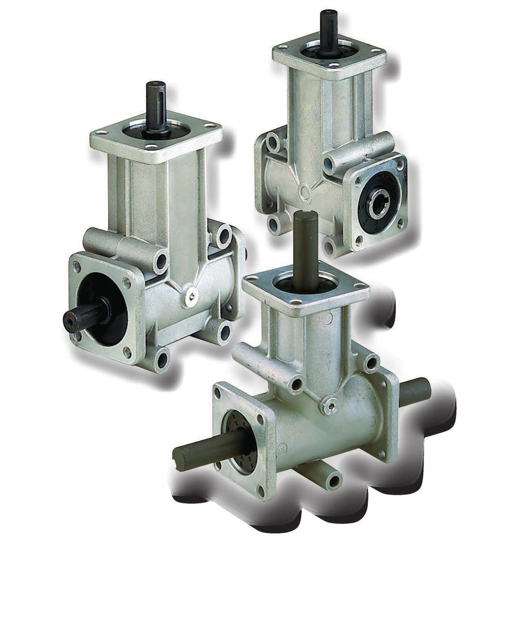

146 RIGHT-ANGLE PRECISION BEVEL GEAR DRIVES
147 RIGHT-ANGLE PRECISION BEVEL GEAR DRIVES CHT-RB and CHT-RP right-angle drives are designed for industrial applications where rotary power must be transferred between two shafts at right-angles to each other. CHT-RB and CHT-RP are available in many different sizes with 2 or 3 outputs and 1/1-1/2-1/3 transmission ratios. Right-angle identification: The following tables show: the shaft diameter, the transmission ratio, the input shaft, the output shafts B-C or D and the direction of rotation (looking at the shaft from the front). SIZE MOD. R B CHT 1 A SHAFT RATIO INPUT OUTPUT TYPE CODE WEIGHT Kg Ø 8 1/1 A B 1 R Ø 8 1/1 A C 2 R B C Ø 8 1/2 A B 3 R Ø 8 1/2 A C 4 R Ø 8 1/1 A B-C 5 R Ø 8 1/2 A B-C 6 R Ø 15 1/1 A B 1 R B A C Ø 15 1/1 A C 2 R Ø 15 1/2 A B 3 R Ø 15 1/2 A C 4 R Ø 15 1/1 A B-C 5 R Ø 15 1/2 A B-C 6 R Ø 20 1/1 A B 1 R RIGHT-ANGLE PRECISION BEVEL GEAR DRIVES 4 B B A A C C Ø 20 1/1 A C 2 R Ø 20 1/2 A B 3 R Ø 20 1/2 A C 4 R Ø 20 1/1 A B-C 5 R Ø 20 1/2 A B-C 6 R Ø 25 1/1 A B 1 R Ø 25 1/1 A C 2 R Ø 25 1/2 A B 3 R Ø 25 1/2 A C 4 R Ø 25 1/1 A B-C 5 R Ø 25 1/2 A B-C 6 R
148 RIGHT-ANGLE PRECISION BEVEL GEAR DRIVES SIZE MOD. R P CHT SHAFT RATIO INPUT OUTPUT TYPE CODE WEIGHT Kg 1 B A C Ø 8 1/1 A B 1 R Ø 8 1/1 A C 2 R Ø 8 1/2 A B 3 R Ø 8 1/2 A C 4 R Ø 8 1/1 A B-C 5 R Ø 8 1/2 A B-C 6 R B A C Ø 14 1/1 A B 1 R Ø 14 1/1 A C 2 R Ø 14 1/2 A B 3 R Ø 14 1/2 A C 4 R Ø 14 1/3 A B 5 R Ø 14 1/3 A C 6 R Ø 14 1/1 A B-C 7 R Ø 14 1/2 A B-C 8 R Ø 14 1/3 A B-C 9 R B A C Ø 14 1/1 A B-C 10 R Ø 14 1/2 A B-C 11 R Ø 14 1/3 A B-C 12 R C B D A Ø 14 1/1 A B-C 13 R Ø 14 1/1 A C-D 14 R Ø 14 1/2 A B-C 15 R Ø 14 1/2 A C-D 16 R Ø 14 1/3 A B-C 17 R Ø 14 1/3 A C-D 18 R Ø 14 1/1 A B-C-D 19 R Ø 14 1/2 A B-C-D 20 R Ø 14 1/3 A B-C-D 21 R B B B A A A C C C Ø 19 1/1 A B 1 R Ø 19 1/1 A C 2 R Ø 19 1/2 A B 3 R Ø 19 1/2 A C 4 R Ø 19 1/3 A B 5 R Ø 19 1/3 A C 6 R Ø 19 1/1 A B-C 7 R Ø 19 1/2 A B-C 8 R Ø 19 1/3 A B-C 9 R Ø 19 1/1 A B-C 10 R Ø 19 1/2 A B-C 11 R Ø 19 1/3 A B-C 12 R Ø 24 1/1 A B 1 R Ø 24 1/1 A C 2 R Ø 24 1/2 A B 3 R Ø 24 1/2 A C 4 R Ø 24 1/3 A B 5 R Ø 24 1/3 A C 6 R Ø 24 1/1 A B-C 7 R Ø 24 1/2 A B-C 8 R Ø 24 1/3 A B-C 9 R RIGHT-ANGLE PRECISION BEVEL GEAR DRIVES
149 HOW TO SELECT THE CORRECT RIGHT-ANGLE TECHNICAL NOTES Selecting the correct type of angle bevel gear is not simply a question of defining the power required in relation to R.P.M. and the torque to be transmitted. If also involves defining the conditions under wich the angle bevel gear will be used. Defining operating conditions involves taking into consideration a number of factor such as the type of operating cycle (intermittent, continuous), radial and axial loads on the shaft ends, maximum and minimum temperatures, ambient conditions (e.g. dust and dirt levels) and the type of lubricant used. To decide the type and size of angle bevel gear required, proceed as follows. 1) Use table 2 to define the Service Factor for your application. 2) Calculate the Rated Power (Pn); Pn = Pe (Horsepower) x FS. 3) Use the output speed and the rated power (Pn) to select the angle gear size and transmission ratio required for your application. 4) Check that the radial and axial load at the midpoint of the exposed shaft end does not exceed the values shown in table 1. 5) Check that the operating temperature does not exceed -20 C 80 C 6) If you require a 1/2 or 1/3 ratio, do not use a speed multiplier with an input more than 750 R.P.M.and 500 R.P.M. in ratio 1/2 and 1/3, respectively. 7) If the unit is to be used in very dusty conditions, protect the oil seal against direct exposure to dust to prevent abrasive damage which might shorten the working life of the unit. TABLE 1 MAX RADIAL AND AXIAL LOADS 144 HOW TO SELECT THE CORRECT RIGHT-ANGLE BEVEL GEAR SIZE MAX AXIAL LOAD IN Kg. MAX RADIAL LOAD IN Kg. RB RB RB RB RP RP2-3/ RP RP TABLE 2 SERVICE FACTOR Fs uniform load load with moderate shocks load with shocks hours of operation for day
150 INPUT POWER (Pn) Output torque T Output speed Output torque 50 rpm 100 rpm 200 rpm 400 rpm 800 rpm 1400 rpm 2000 rpm 3000 rpm T power T power T power T power T power T power T power T power Type Ratio Nm Kw Nm Kw Nm Kw Nm Kw Nm Kw Nm Kw Nm Kw Nm Kw RB 1-1/2- RB 1-5 4,7 0,02 3,9 0,04 3,3 0,07 2,8 0,12 2,3 0,19 2,0 0,30 1,8 0,39 1,7 0,53 RP 1-1/2- RP 1-5 9,1 0,05 7,6 0,08 6,4 0,13 5,4 0,23 4,5 0,38 4,0 0,58 3,6 0,76 3,3 1,03 RB 2-1/2- RB ,5 0,09 13,9 0,15 11,7 0,24 9,8 0,41 8,2 0,69 7,2 1,05 6,6 1,37 5,9 1,86 RP ,8 0,15 24,2 0,25 20,3 0,43 17,1 0,72 14,4 1,20 12,5 1,83 11,4 2,39 10,3 3,25 RP 2-1/2 RP 4-13/14 RP 2-7 R 1:1 34,5 0,18 29,0 0,30 24,4 0,51 20,5 0,86 17,2 1,44 15,0 2,20 13,7 2,87 12,4 3,89 RP 4-19 RB 3-1/2 53,1 0,28 44,6 0,47 37,5 0,79 31,6 1,32 26,5 2,22 23,1 3,38 21,1 4,42 19,1 5,99 RB 3-5 RP ,7 0,40 63,7 0,67 53,5 1,12 45,0 1,89 37,9 3,17 32,9 4,82 30,1 6,30 27,2 8,54 RB 4-1/2 - RP 5-1/2 RP 7-1/2- RB 4-5 RP 5-7- RP ,3 0,46 73,4 0,77 61,8 1,29 51,9 2,17 43,7 3,66 38,0 5,56 34,7 7,27 31,4 9,86 RB 1-3/4- RB 1-6 4,0 0,02 3,4 0,04 2,8 0,06 2,4 0,10 2,0 0,17 1,7 0,26 1,6 0,33 1,4 0,45 RP 1-3/4- RP 1-6 8,9 0,05 7,5 0,08 6,3 0,13 5,3 0,22 4,4 0,37 3,9 0,57 3,5 0,74 3,2 1,00 RB 2-3/4- RB ,6 0,08 12,3 0,13 10,3 0,22 8,7 0,36 7,3 0,61 6,3 0,93 5,8 1,21 5,2 1,65 RP ,1 0,15 23,7 0,25 19,9 0,42 16,7 0,70 14,1 1,18 12,2 1,79 11,2 2,34 10,1 3,17 RP 2-3/4 RP 4-15/16 RP 2-8 R 1:2 RP 4-20 RB 3-3/4-RB 3-6 RP ,8 42,5 71,3 0,18 0,22 0,37 28,5 35,7 59,9 0,30 0,37 0,63 23,9 30,1 50,4 0,50 0,63 1,06 20,1 25,3 42,4 0,84 1,06 1,77 16,9 21,3 35,6 1,42 1,78 2,98 14,7 18,5 31,0 2,16 2,71 4,54 13,5 16,9 28,3 2,82 3,54 5,93 12,2 15,3 25,6 3,82 4,80 8,04 RB 4-3/4 - RP 4-6 RP 7-3/4- RB 4-6 RP 5-8- RP ,3 0,43 69,2 0,72 58,2 1,22 48,9 2,05 41,1 3,44 35,8 5,24 32,7 6,85 29,6 9, RP 2-5/6 RP 2-9 RP 3-12 RP 4-17/18 RP 4-21 RP 5-5/6 RP 5-9 RP 6-12 RP 7-5/6 RP 7-9 R 1:3 27,5 0,14 23,1 0,24 19,4 0,41 16,3 0,68 13,7 1,15 12,0 1,75 10,9 2,29 9,9 3,10 63,4 0,33 53,3 0,56 44,9 0,94 37,7 1,58 31,7 2,66 27,6 4,04 25,2 5,28 22,8 7,16 INPUT POWER (Pn) OUTPUT TORQUE T
151 RIGHT-ANGLE PRECISION BEVEL GEAR DRIVES EXTERNAL LOADS IN CONNECTION WITH SPEED Fr = radial load Fa = axial load Output speed Radial - axial load Type Ratio 50 rpm 100 rpm 200 rpm 400 rpm 800 rpm 1400 rpm 2000 rpm 3000 rpm Fr Fa Fr Fa Fr Fa Fr Fa Fr Fa Fr Fa Fr Fa Fr Fa N N N N N N N N N N N N N N N N RB 1-1/2- RB RP 1-1/2- RP RB 2-1/2- RB RP RP 2-1/2 RP 4-13/14 RP 2-7 R 1: RP 4-19 RB 3-1/ RB 3-5 RP RB 4-1/2 - RP 5-1/2 RP 7-1/2- RB 4-5 RP 5-7- RP RB 1-3/4- RB RP 1-3/4- RP RB 2-3/4- RB RP RP 2-3/4 RP 4-15/16 RP 2-8 R 1:2 RP 4-20 RB 3-3/4-RB RP RB 4-3/4 - RP 4-6 RP 7-3/4- RB 4-6 RP 5-8- RP RP 2-5/6 RP 2-9 RIGHT-ANGLE PRECISION BEVEL GEAR DRIVES RP 3-12 RP 4-17/18 RP 4-21 RP 5-5/6 RP 5-9 RP 6-12 RP 7-5/6 RP 7-9 R 1:
152 RIGHT-ANGLE PRECISION BEVEL GEAR DRIVES SIZE 1 MOD. R B CHT RATIO INPUT OUTPUT CODE WEIGHT Kg B A C 1/1 A B R /1 A C R /2 A B R /2 A C R /1 A B-C R /2 A B-C R (x 3) Holes 5 (x 3) Holes x 3 flanges (x 3) 2,5 (x 3) SIZE 2 MOD. R B CHT RATIO INPUT OUTPUT CODE WEIGHT Kg B A C 1/1 A B R /1 A C R /2 A B R /2 A C R /1 A B-C R /2 A B-C R Holes x 3 flanges Oil plug 3 Holes RIGHT-ANGLE PRECISION BEVEL GEAR DRIVES
153 RIGHT-ANGLE PRECISION BEVEL GEAR DRIVES SIZE 3 MOD. R B CHT RATIO INPUT OUTPUT CODE WEIGHT Kg B A C 1/1 A B R /1 A C R /2 A B R /2 A C R /1 A B-C R /2 A B-C R Oil plug Holes Holes x 3 flanges 148 SIZE 4 MOD. R B CHT RATIO INPUT OUTPUT CODE WEIGHT Kg B A C 1/1 A B R /1 A C R /2 A B R /2 A C R /1 A B-C R /2 A B-C R RIGHT-ANGLE PRECISION BEVEL GEAR DRIVES Holes x 3 flanges Oil plug Holes
154 RIGHT-ANGLE PRECISION BEVEL GEAR DRIVES SIZE 1 MOD. R P CHT RATIO INPUT OUTPUT CODE WEIGHT Kg B A C 1/1 A B R /1 A C R /2 A B R /2 A C R /1 A B-C R /2 A B-C R Holes Holes x 2 flanges Holes 149 SIZE 2 MOD. R P CHT RATIO INPUT OUTPUT CODE WEIGHT Kg B A C 1/1 A B R /1 A C R /2 A B R /2 A C R /3 A B R /3 A C R /1 A B-C R /2 A B-C R /3 A B-C R Holes x 2 flanges Holes Oil plug 2 RIGHT-ANGLE PRECISION BEVEL GEAR DRIVES
155 RIGHT-ANGLE PRECISION BEVEL GEAR DRIVES SIZE 3 MOD. R P CHT RATIO INPUT OUTPUT CODE WEIGHT Kg B A C 1/1 A B-C R /2 A B-C R /3 A B-C R Hub Holes Oil plug Holes x 3 flanges 150 SIZE 4 MOD. R P CHT RATIO INPUT OUTPUT CODE WEIGHT Kg RIGHT-ANGLE PRECISION BEVEL GEAR DRIVES C B D A 1/1 A B-C R /1 A C-D R /2 A B-C R /2 A C-D R /3 A B-C R /3 A C-D R /1 A B-C-D R /2 A B-C-D R /3 A B-C-D R Holes x 4 flanges Holes Oil plug 3.2
156 RIGHT-ANGLE PRECISION BEVEL GEAR DRIVES SIZE 5 MOD. R P CHT RATIO INPUT OUTPUT CODE WEIGHT Kg B A C 1/1 A B R /1 A C R /2 A B R /2 A C R /3 A B R /3 A C R /1 A B-C R /2 A B-C R /3 A B-C R Oil plug Holes Holes x 2 flanges Holes 151 SIZE 6 MOD. R P CHT RATIO INPUT OUTPUT CODE WEIGHT Kg B A C 1/1 A B-C R /2 A B-C R /3 A B-C R Holes x 2 flanges Hub Oil plug Holes Holes RIGHT-ANGLE PRECISION BEVEL GEAR DRIVES
157 RIGHT-ANGLE PRECISION BEVEL GEAR DRIVES SIZE 7 MOD. R P CHT RATIO INPUT OUTPUT CODE WEIGHT Kg B A C 1/1 A B R /1 A C R /2 A B R /2 A C R /3 A B R /3 A C R /1 A B-C R /2 A B-C R /3 A B-C R Oil plug Holes Holes x 2 flanges Holes 152 RIGHT-ANGLE PRECISION BEVEL GEAR DRIVES


158 ELECTRIC MOTORS
159 INTRODUCTION CHT series motors have been produced to be mounted on gearboxes and therefore they have mechanical and electrical characteristics particularly right for this use. All our motors are IP55, insulation class F with phase separator to be used with frequency variators, in this condition they can be provided complete with forced ventilation. The motors like the gearboxes are painted with RAL 9022 grey colour epoxy powder. TECHNICAL CHARACTERISTICS - Cage rotor motors, locked with outside surface ventilation. - Project, construction and test in compliance with CEI2-3, international norms IEC34-1 and principal foreign/international standard. - Power-sizes in specification with IEC 72, national norms UNEL-MEC. - Insulation: class F - Protection: class IP55 - Rated power delivered on continuous: S1 - European directive ROHS 2002/95/CE - Phase separator - Motors size 160 up to Volt 400/690 standard from 160 up to 355 on request for other sizes 154 INTRODUCTION - TECHNICAL CHARACTERISTICS
160 FUNCTION WITH A FREQUENCY OF 60 The CHT line motors can function with a frequency of 60 Hz. with differences in performances and electrical sizes as described on the table. PLATE VOLTAGE PLATE VOLTAGE NOMINAL NOMINAL NOMINAL R.P.M. STARTING STARTING MAX TORQUE POWER CURRENT TORQUE CURRENT TORQUE 50 Hz 60 Hz 230 +/- 10% 220 +/- 5% /- 10% 230 +/- 10% /- 10% 254 +/- 5% /- 10% 277 +/- 5% /- 10% 380 +/- 5% /- 10% 400 +/- 10% /- 10% 440 +/- 5% /- 10% 460 +/- 10% /- 10% 480 +/- 5% FEEDING VOLTAGE The CHT line motors are made to be used on the European net system Volt 230/400 +/- 10% - Hz 50 and Volt 400/690 +/- 10% - Hz 50 This means that the same motor can function on the following stili existing nets: - 220/380 Volt +/- 5% - 230/400 Volt +/- 10% - 240/415 Volt +/- 5% - 380/660 Volt +/- 5% - 400/690 Volt +/- 10% - 415/720 Volt +/- 5% corresponding to the requirements requested by the rules of numerous countries. 155 FUNCTION WITH A FREQUENCY OF 60 - FEEDING VOLTAGE

161 ELECTRIC MOTORS 2/4/6 POLES IE 1 TYPE POLES POWER VOLTAGE CURRENT TORQUE EFFICIENCY FACTOR WEIGHT Kw V 400 V N/m % COS.ø Kg. CHT 56 B / CHT 56 B / CHT 63 A / CHT 63 B / CHT 63 C / CHT 63 A / CHT 63 B / CHT 63 C / CHT 63 B / CHT 71 A / CHT 71 B / CHT 71 A / CHT 71 B / CHT 71 C / CHT 71 A / CHT 71 B / CHT 71 C / CHT 80 A / CHT 80 A / CHT 80 B / ELECTRIC MOTORS 2/4/6 POLES - IE 1

162 ELECTRIC MOTORS 2/4/6 POLES IE 2 IE 2 EFFICIENCY MOTORS Starting from June 2011, poles electric motors with power included from 0,75kw to 375kw. sold into European Community, must be in accordance with EU MEPS European Union Minimum Energy Performance Standards regulation concerning efficiency level, in order to reduce consumptions and C02 emissions. IE 2 mark reported on the motors nameplate will show that it belongs to this class. TYPE POLES POWER VOLTAGE CURRENT TORQUE EFFICIENCY FACTOR WEIGHT Kw V 400 V N/m % COS.ø Kg. CHT 80 A / CHT 80 B / CHT 80 C / CHT 80 B / CHT 80 C / CHT 90 S / CHT 90 L / CHT 90 S / CHT 90 L / CHT 90 M / CHT 90 S / CHT 90 L / CHT 100 LA / CHT 100 LA / CHT 100 LB / CHT 100 LA / CHT 112 M / CHT 112 M / CHT 112 L / CHT 112 M / CHT 132 SA / CHT 132 SB / CHT 132 S / CHT 132 M / CHT 132 M / CHT 132 S / * Motors size 160 up to 355 on request * Volt 400/690 standard from 160 up to 355 on request for other sizes. * ABB motor available on request * MGM brake motor available on request ELECTRIC MOTORS 2/4/6 POLES - IE2
163 THREE-PHASE ELECTRIC MOTORS b L G S v d C B5 M B b H L I F G d S v C B14 F M B H I b L 158 G d B3 B T AD H R BB A SIZES AND DIMENSIONS THREE-PHASE ELECTRIC MOTORS TYPE MOUNTING DIMENSIONS (mm) DIMENSIONS B5 B14 B3 d H b G I M F V S I M F V S R BB A T AD B C L M M M M S M L/90LL M L M M M S M M M
164 FORCED VENTILATION KIT* SINGLE-PHASE MODELS L x L F C G A internal diameter B E D Single-phase dimensions with IP55 terminal box SIZE VOLTAGE HZ NOM. SPEED MIN/1 ABSORB. WATT CURRENT M.A. AIR FLOW M 3/H 159 GR / / / GR / / / GR / / / GR / / / GR / / / GR / / / GR / / / SIZE COD. IP55 A B C D E F G L x L GR.63 AS GR.71 AS GR.80 AS GR.90 AS GR.100 AS GR.112 AS GR.132 AS * forced ventilation kit three-phase models available on request FORCED VENTILATION KIT* SINGLE-PHASE MODELS


165 BELT TENSIONER SLIDES FOR ELECTRIC MOTORS
166 BELT TENSIONER SLIDES FOR ELECTRIC MOTORS MATERIAL Galvanized metal sheet FE 430 L G G J B N K K P SW S C 30 E C M mm E V H DIMENSIONS MOTOR TYPE CODE L B H Mmin G E J K C N P SW S SIZE 63/ , / , / ,5 12, / ,5 12, / / ADJUSTMENT WIDENESS TYPE WEIGHT kg , , , , ,8 Quantities, prices and availability by B2B Chiaravalli BELT TENSIONER SLIDES FOR ELECTRIC MOTORS

167 The Chiaravalli group is the technological partner that you should turn to knowing that reliability and respect are values commonly shared.

168 THE CUSTOMER: ALWAYS AT THE CENTRE OF OUR ATTENTION. The Chiaravalli group is a dynamic, modern company oriented in fulfilling customers needs and desires. Human progress has always been based on mechanical application and discovery that stem from human intutition and genius. Mechanics: the genetic heritage of Chiaravalli Group The Chiaravalli Group, always aware of the needs of the market has found it necessary to provide its long-standing customers with complete, steady up-dated information about its products 24 hours a day 365 days in a year. This attention comes from B2B, which is the direct consequence of our interest and dedication to our customers. It is an advanced system of research, purchasing and delivery of all Chiaravalli products. B2B Chiaravalli Group becomes a virtual extension of the customer s warehouse.
169 GENERAL SALES CONDITIONS 1) ORDERS - Orders for special and standard material must always refer to offers made by CHIARAVALLI GROUP S.p.A. The orders are binding for the client. Once work has commenced no cancellations or order reductions will be accepted unless the client reimburses the costs of the material and the work carried out up to the moment in which the order was suspended. The quantity despatched can vary by ± 5% compared to the quantity ordered. 2) PRICES - The prices are those in force at the date of order. All prices are for goods delivered ex-works Premezzo, packing excluded. If there should be any increase in production and material costs over the duration of the supply, CHIARAVALLI GROUP S.p.A. reserves the right to adapt the prices accordingly, even for orders in course. 3) TERMS OF DELIVERY - Only the terms of delivery indicated by CHIARAVALLI GROUP SpA are to be considered valid. However, they must only be considered as indicative. In the event of difficulty in the procurement of materials, strikes or in any event in all cases of force majeure, the terms of delivery will be automatically extended without CHIARAVALLI GROUP S.p.A having to pay any reimbursement for damages. The client is obligated to collect special material ordered when ready. 4) DELIVERIES - Deliveries are the responsibility of the purchaser and are carried out at his own risk and peril. Any claims for shortages must be presented within 8 days of receipt of the goods. If it is agreed that the cost of transport is to be paid, even if only in part, by CHIARAVALLI GROUP S.p.A., the latter reserves the right to choose the most economical means of transport. 5) PACKING - Packing will be invoiced at cost. 6) RETURNS - No returns for any reason will be accepted unless previously authorised and with packing, any customs clearance and the return paid for by the purchaser. To cover warehouse and administrative expenses a debit note will be issued for approx. 15% of the value of the goods returned. 7) WARRANTY - CHIARAVALLI GROUP S.p.A. promises to repair or substitute free of charge any parts that they recognise as being defective. The questioned goods must be returned to the factory of CHIARAVALLI GROUP S.p.A., free of all expenses. The warranty will be considered cancelled in the event that the parts returned as defective have been repaired or tampered with. The repair of defective parts carried out by the purchaser will only be accepted after authorisation from CHIARAVALLI GROUP S.p.A. and after their approval of the cost estimate. CHIARAVALLI GROUP S.p.A. does not accept responsibility or pay any reimbursement for damages that occur during the use of their products, even if defective. Warranty is excluded for leakage of lubricant caused by wear of the oil seals. 8) RESPONSIBILITY - CHIARAVALLI GROUP S.p.A. does not accept responsibility or pay any reimbursement for damages that occur during the use of their products, even if defective. CHIARAVALLI GROUP S.p.A. declines all responsibility in the execution of parts to a client s design under any patents. GENERAL SALES CONDITIONS 9) PAYMENTS - Only payments carried out in the manner and terms agreed will be considered valid. Once the due date of payment has passed, CHIARAVALLI GROUP S.p.A. will calculate the interest on delayed payment at a rate that is 3% higher than the legal one, retaining the right to demand payment. In the event of delayed or missing payment by the purchaser, the company CHIARAVALLI GROUP S.p.A. reserves the right to suspend deliveries of the orders in course or to demand advance payment without having to pay any reimbursement or compensation to the purchaser. Any dispute regarding materials in manufacture or already possessed by the purchaser does not free the latter from the commitment of making the payment by the agreed date and for the whole amount of the invoice without making any deductions. 10) OWNERSHIP - All of the goods despatched remain the property of CHIARAVALLI GROUP S.p.A. until the invoice is fully paid. 11) COMPETENT COURT - Any controversy concerning business relations with CHIARAVALLI GROUP SpA will be dealt with under the jurisdiction of the Court of Busto Arsizio. CHIARAVALLI GROUP SpA, do not accepts responsibility for any errors in the production of this catalogue and reserves the right to add to the drawings designs of the listed products any modification request by manufacturing requirements or due to evolution of the products.
 Italy Tel. +39 0331 214 511 Fax +39 0331 218 175 www.chiaravalli.com chiaravalli@chiaravalli.")
170 CHIARAVALLI Cz a.s. Prumyslová Velké Mezirící Ceská republika Tel CHIARAVALLI POLSKA Sp. z o. o. ul. Polna Torun Polska Tel Via per Cedrate, Cavaria con Premezzo (VA) Italy Tel Fax chiaravalli@chiaravalli.com Satellite position: coordinates N E
CHC SERIES HELICAL GEAR UNITS
 CHC SERIES HELICAL GEAR UNITS INTRODUCTION CHC series helical gear units is a new generation product, which designed basing on the modular system. It can be connected respectively with motors such as standard
CHO HELICAL-HYPOID GEAR UNITS
 CHO HELICAL-HYPOID GEAR UNITS Kuželočelní převodovky INTRODUCTION CHO helical hypoid gear units have been conceived to be used instead of worm gearboxes where high efficiency is requested, especially with
CHB WORM GEARED MOTORS AND WORM GEAR UNITS ACCESSORIES FOR GEAR BOXES AND ELECTRIC MOTORS
 CHB WORM GEARED MOTORS AND WORM GEAR UNITS ACCESSORIES FOR GEAR BOXES AND ELECTRIC MOTORS 03.08 INDEX Introduction Page CHB 03-04-05 Worm geared motors and worm gear units Page 2 CHB CHB..P 03-04-05 designation
NMRV - MCV - NRV NMRV+NMRV PC+NMRV
 MAINTENANCE AND OPERATING INSTRUCTIONS FOR WORM GEAR REDUCERS AND GEARMOTORS SERIES: NMRV - MCV - NRV NMRV+NMRV PC+NMRV GB NMRV-UM-9 99/01 rev.15.07.99 2 Warehouse storage When moving the unit, care should
Your Partner in Solutions 24/7. EMAW Worm Gearboxes. Tel: Fax: Web:
 Your Partner in Solutions 24/7 EMAW Worm Gearboxes Tel: 01902 601 403 Fax: 01902 601 408 Email: sales@emag-ltd.co.uk Web: www.emag-ltd.co.uk Worm Gear Units - Installation & Lubrication To install the
DRIVES, CONTROLLERS & COUPLINGS CATALOGUE
 Ashley Power Ltd. 580-586 Ashley Road Parkstone Poole Dorset, BH14 0AQ DRIVES, CONTROLLERS & COUPLINGS CATALOGUE Tel: +44 (0) 1202 746031 Fax: +44 (0) 1202 741108 Email: sales@ashleypower.co.uk Inverters,
Versions. f.s. Worm gear units CMRV CMRV-CMRV... PC-CMRV... CRV CRV-CMRV...
 Worm Gear Units 313 Versions CMRV 025-150 The service factor (f.s.) depends on the operating conditions the reduction unit is subjected to. The parameters that need to be taken into consideration to select
MAINTENANCE AND USE INSTRUCTIONS FOR WORM GEAR REDUCERS AND GEARMOTORS SERIES: SW - ISW - SW+SW ISW+SW
 MAINTENANCE AND USE INSTRUCTIONS FOR WORM GEAR REDUCERS AND GEARMOTORS SERIES: SW - ISW - SW+SW ISW+SW GB 2 Warehouse storage When moving the unit, care should be taken to protect external parts from breakage
HSERIES. Helical geared motors
 HSERIES Helical geared motors Design features Motovario products are supplied with the following surface treatment features: Die-cast aluminium alloy cases for gears Die-cast materials undergo the following
NMRV SERIES WORM-GEAR SPEED REDUCERS
 NMRV SERIES WORMGEAR SPEED REDUCERS TRASMITAL GEAR INDIA PVT LTD Brief introduction to wormgear speed reducer Trasmital NMRV series wormgear speed reducer is a newgeneration product developed by our company
HYDRAULIC COMPONENTS HYDROSTATIC TRANSMISSIONS GEARBOXES - ACCESSORIES HT 14 / A / 103 / 0309 / E
 HYDRAULIC COMPONENTS HYDROSTATIC TRANSMISSIONS GEARBOXES - ACCESSORIES HT 14 / A / 103 / 0309 / E Pump Drives - Gearboxes Mechanical Dry Clutches Hydraulic Clutches Pump Adaptors CONTENTS Pump Drives AM
B SERIES. Helical bevel Gear Reducers
 Helical bevel Gear Reducers FEATURES The technological content of -Series gear reducers allows for an extraordinary performance/lifespan ratio. These highly versatile gear units are successfully used in
WGM SERIES WORM GEARED MOTORS WGM 063 FA 30 DI SO Φ25 PAM80B14 B3
 WORM GEARBOXES WORM GEARBOXES page 2 of 17 WGM SERIES WORM GEARED MOTORS BRIEF INTRODUCTION Our worm gear speed reducers range WG and WGM are characterized by a kinematic motion made of a casehardened
Bevel gearboxes. Catalogue
 Bevel gearboxes Catalogue INDEX Bevel gearbox description... page 2 Manufacturing features... page 2 Materials and components... page 4 Bevel gearbox selection... page 5 Thermal power limit... page 7
Helical Gear Motors BEGE Type G & M. Your drive, our (trans)mission. BEGE Power Transmission
mission. BEGE Power Transmission") Helical Gear Motors BEGE Type G & M BEGE Power Transmission Anton Philipsweg 30 2171 KX Sassenheim The Netherlands T: +31 252-220 220 E: bege@bege.nl W: www.bege.nl Your drive, our (trans)mission General
Helical Gear Motors BEGE Type G & M BEGE Power Transmission Anton Philipsweg 30 2171 KX Sassenheim The Netherlands T: +31 252-220 220 E: bege@bege.nl W: www.bege.nl Your drive, our (trans)mission General
Shaft Mounted Speed Reducer. Technical Catalogue
 Shaft Mounted Speed Reducer Technical Catalogue Where others fit, We perform Contents The Challenge SMSR stands tall amongst the crowd. Packed full of attention to detail, the Challenge SMSR delivers performance
TECHNICAL CHARACTERISTICS
 GEARBOX WM 26 8 Nm TECHNICAL CHARACTERISTICS Worm gearbox. Life-time lubrication by grease, therefore it is main tenance-free. Housing. Die-casting aluminium. Worm-shaft. Hardened steel with grinding.
Electromechanical products Poulibloc. General information
 Poulibloc General information Poulibloc geared motors with parallel gears are used to adapt the speed of the electric motor to that of the driven machine. Their size is therefore determined by the motor
Operating Instructions
 Operating Instructions Table of contents Table of contents... 1 1. Declaration... 1 2. Warranty and liability... 2 3. Gear description... 2 4. Gear types... 2 5. Safety... 3 5.1 General safety information...
SHAFT MOUNTED HELICAL GEAR REDUCER
 Shaft Mounted Helical Gear Assembly INTRODUCTION The VIGNESSH Shaft Mounted Helical Gear Units are the result of experience in design and production, taking advantage of the most recent relevent research
INSTRUCTIONS FOR USE FACE GEARBOXES
 INSTRUCTIONS FOR USE FACE GEARBOXES TNC MTC-TC KTM ES Declaration of Conformity Producer: TOS ZNOJMO, akciová společnost Družstevní 3 CZ 669 02 Znojmo Equipment: Face gearboxes Type/ Modification:MTC,
Shaft Mounted Speed Reducers
 s Metric Range Features The Challenge SMSR stands tall amongst the crowd. Packed full of attention to detail, the Challenge SMSR delivers performance in the harshest of applications. Shaft mounted drives
technology made in Italy
 technology made in Italy GB RD * * VS made in China Technology Made in Italy Since 1955 Varvel has been making speed reducers and variators for light industry applications. Reliable partner in power transmission
RS & RT WORM GEAR BOXES
 RS & RT WORM GEAR BOXES C-MRS-MRT ed0-2009 rev00 GB Product Description Multipurpose housing Aluminium die cast & Grey Iron Modular for all mountings Wormshaft ZI profile, hardened and ground. Alloy steel.
Section 9: Gearboxes: Series W
 GEARBOXES Section : 9 Section 9: Gearboxes: Series W A modular designed aluminium worm box available in a vast range of sizes and ratios for cost effective solutions. 9 s with ratings from 0.09 to 7.5kW
SERIES NEW PARALLEL HELICAL AND BEVEL HELICAL GEARBOXES PARALLEL HELICAL AND BEVEL HELICAL GEARBOXES
 SERIES NEW PARALLEL HELICAL AND BEVEL HELICAL GEARBOXES PARALLEL HELICAL AND BEVEL HELICAL GEARBOXES 1 2 SERIES 1 2 pag. pag. 5 Introduction Features 3 pag. pag. Versions Range and designation 5 pag. 9
Handbuch für installation, betrieb und wartung Planetengetriebe
 Italy Headquarters Installation, use and maintenance manual Manuale Installazione Uso e Manutenzione Riduttori Epicicloidali Installation, Operation and Service Manual Handbuch für installation, betrieb
HL - MHL SPA SOCIETÀ ITALIANA TRASMISSIONI INDUSTRIALI. INSTALLATION, OPERATION and MAINTENANCE MANUAL
 SPA SOCIETÀ ITALIANA TRASMISSIONI INDUSTRIALI HL - MHL TM INSTALLATION, OPERATION and MAINTENANCE MANUAL 03.2005 Table of contents Contacting our service department... 4 Operation... 5 Maintenance... 6
Motor driven diaphragm metering pump P D S V N PUMP HEAD MATERIAL. O RING V FKM B D Dutral LUBRICANT TYPE
 Motor-driven diaphragm dosing pump, mechanical actuated, PRIUS combines efficiency and chemical resistance to a wide capacity range for an extensive number of applications. ATEX II 2 G c IIB T3, T4 II
KEB Gear units & Motors 2014
 Introduction KEB Gear units & Motors 2014 Contents Introduction 2 designation... 2 Product description... 3 Assembly / Disassembly notes when using gear units with hollow shaft... 5 Drive selection...
Speed Correction Drives
 Speed Correction Drives For Shaft Phasing and Narrow Range Speed Control Low Backlash Low Transmission Error Wide Range of Ratios Variety of Specialty Models AVAILABLE THROUGH Motion Components and Engineering
Planetary Gearboxes. cat planetarios 200 pags 2008.in1 1 31/03/ :49:57
 Planetary Gearboxes cat planetarios 200 pags 2008.in1 1 31/03/2009 10:49:57 Table of contents Description Page Symbols, units of measure and description 4-4 Technical characteristics and general information
KAVITSU Excellence in Gear Technology. The compact And Efficient
 KAVITSU Excellence in Gear Technology The compact And Efficient OUR RANGE OF PRODUCT PLANETARY SPEED REDUCER TORQUE :- 0 Nm TO 50 00 000 Nm :- : TO 00000 : POWER :- 0.8 KW TO 000 KW MOUNTING :- FOOT, FLANGE,
CERTIFIED MANAGEMENT SYSTEM
 EN RS RT CERTIFIED Technology Made in Italy Since 955 Varvel has been making speed reducers and variators for light industry applications. Reliable partner in power transmission equipment offers also customized
5 Gear units, types of installation, lubricant quantities. 5.1 Standard fitting positions/ types of installation for Bauer geared motors
 26 5 Gear units, types of installation, lubricant quantities 5.1 Standard fitting positions/ types of installation for Bauer geared motors 5 27 28 5.2 Position of the terminal box and the cable entry points
Catalogue geared motors. Edition 01/
 Catalogue geared motors Edition 0/0 Page Gearboxes and Lubrication Standard fitting - BG and BF - BK and BS Position of the terminal box and the cabel entry - BG and BF - BK and BS Radial and axial forces
SINGLE PHASE TEFC CAGE MOTORS
 SINGLE PHASE TEFC CAGE MOTORS 2 SINGLE PHASE TEF CAGE MOTORS Mechanical protection: IP 54 Voltage: 220 V, 50 Hz Type Output power P N kw Rated speed n N min -1 Efficiency % Power factor cos Rated current
3947 en / b
 3947 en - 06.2006 / b FOOD INDUSTRY Drive systems As a worldwide specialist in drive systems, industrial processes and generators, LEROY-SOMER has supported its customers evolving needs for more than 80
Series J Shaft Mounted Gearbox
 Series J Shaft Mounted Gearbox Technical Up to - 600kW / 57,000 Nm Industrial Gearbox CJ-2.00GBA1211 PRODUCTS IN THE RANGE Serving an entire spectrum of mechanical drive applications from food, energy,
The FRS worm geared motor units are outstanding examples of the diverse range and
 The FRS worm geared motor units are outstanding examples of the diverse range and product performance that has built the MG name. The FRS series ranges up to 1500Nm, 0.09 to 15kW, and offers adaptability,
CYLINDRICAL CAM INDEXING ROTARY TABLES IR TABLES HEAVY SERIES IR IR IR 2001 COLOMBO FILIPPETTI SPA
 CYLINDRICAL CAM INDEXING IR HEAVY SERIES COLOMBO FILIPPETTI SPA Sealed electrowelding gear housing. Indexing output plate with fixed central through hole. Input shaft and worm screw on opposite taper roller
 http://www.dongco.com/ Contents Service factor & Installation notice 2 Worm geared motors and worm gear units 4 Input flange Dimensions 6 Mesh data 7 NMRV NMRV Performance 8 http://www.dongco.com/ NRV
Power Jacks have taken time, engineering excellence and the best people to produce the ultra compact Neeter Drive gearbox.
 202 www.powerjacks.com Power Jacks have taken time, engineering excellence and the best people to produce the ultra compact Neeter Drive gearbox. Our expertise has been built on a history of engineering
HP High-Performance Gear Units with <2' Adjustable Backlash
 Page HP High-Performance Gear Units with
SUDARSHAN GEARS ISO CERTIFIED COMPANY MADE IN INDIA ALUMINIUM WORM GEAR BOXES
 ALUMINIUM WORM GEAR BOXES Plot N. 7, Mira Co-op industrial Estate, National Highway No. 8, KashiMira Naka, Mira Road (E), Dist. Thane - 4004. India Tel.: 022 28455990/9/85 Fax No.: 022-28455982 Email:
Explosion and flame-proof single phase electric motors
 Explosion and flame-proof single phase electric motors EEx-d, EEx-de, IIB, IIC II, 2G IP55 II, 2G&D IP66 T4, T5, T6 Frame size 56 to 112 Single phase Voltage 230 50Hz Voltage 265 60Hz Types of mounting
Explosion and flame-proof cast iron electric motors
 Explosion and flame-proof cast iron electric motors EEx-d, EEx-de, IIB, IIC II, 2G IP55 II, 2G&D IP66 T4, T5, T6 Frame size 56 to 160 3 phases Voltage 230/400 V 50Hz Voltage 265/460V 60Hz Types of mounting
SERVO MOTORS BRUSHLESS SERVO MOTORS OPERATING INSTRUCTIONS 2016
 SERVO MOTORS BRUSHLESS SERVO MOTORS OPERATING INSTRUCTIONS 2016 3009/16 en Ed.02.2016 Read these Operating Instructions before performing any transportation, installation, commissioning, maintenance or
Certified Quality System UNI EN ISO 9001 : 2008 SERVICE MANUAL PGRF series Release A10/14
 312 Certified Quality System UNI EN ISO 9001 : 2008 www.comerindustries.com SERVICE MANUAL PGRF series Release A10/14 INDEX GENERAL INFORMATION... 3 GEARBOX UNIT IDENTIFICATION... 3 RISKS AND PRECAUTIONS...
Planning Section. Environmental conditions. Different power supply. Industrial solutions
 Planning Section 86 89 Environmental conditions Different power supply 90 Industrial solutions 91 Power calculation and selection of the Motorized Pulley for package transportation 93 Oil types and contents
314 ORDINARY MAINTENANCE MANUAL FOR. PGA series VERTICAL MOUNTING POSITION. Release A02/15
 314 www.comerindustries.com ORDINARY MAINTENANCE MANUAL FOR PGA series VERTICAL MOUNTING POSITION Release A02/15 INDEX General information...page 3 Ordinary maintenance...page 4 Oil lubricant replacement...page
"U" TROUGH SCREW CONVEYOR CNU SERIES. OPERATING MANUAL FOR INSTALLATION, OPERATING AND MAINTENANCE
 "U" TROUGH SCREW CONVEYOR CNU SERIES. OPERATING MANUAL FOR INSTALLATION, OPERATING AND MAINTENANCE SPEC. 11/08 Part 1 KEEP THIS MANUAL FOR FUTURE CONSULTATIONS Dear Client, We thank you for choosing our
Hoist Brake Motor. Hoist Gearbox Reeving Wire Rope Construction
 DR11 Monorail Hoist Hoist Brake Motor Hoist Gearbox Reeving Wire Rope Construction Rope Drum Trolley Brake Motor Trolley gearbox Trolley Trolley Wheels Load Block Hoist VFD Controls Trolley VFD Controls
CORE VALUES TECHNOLOGIES ESS-ESD PRODUCT CATALOGUE Enjoy the peace of mind ENGINE POWER SUPPLIERS AND EQUIPMENT HEAT
 TECHNOLOGIES ENGINE POWER SUPPLIERS AND EQUIPMENT HEAT Enjoy the peace of mind ESS-ESD PRODUCT CATALOGUE CORE VALUES PEACE OF MIND EFFICIENCY FAIRNESS RESPONSIBILITY CUSTOMER ORIENTATION GROWING DEVELOPED
Roller chains TPM - QRC pag. 40 Roller chains RCX pag. 43 Conveyor chains CRT pag. 45 Chain guide rails in polyethylene pag. 48
 INDEX Sprockets - Platewheels pag. 2 Asa sprockets - platewheels pag. 20 Duplex platewheels for two simple chains pag. 26 Stainless steel sprockets - Aisi 304 L - Simplex sprockets hardened teeth pag.
PARAMAX Series. Agitator Drives CW11
 PARAMAX Agitator Drives 9000 Series CW No. G60E-.0 No. G60E- Agitator Drives Features.Easy to mount Flange mounting Compact gearbox allows simpler mounting base. Oil pump requires no electricity..compact
Speed Reducers and Gearmotors
 ofc BEVEL BUDDYBOX Speed Reducers and earmotors CATALO 13.605.50.001 Bevel Buddybox Rugged Spiral Bevel Output Modular Cyclo Input Compact Size Two-Year Warranty Eccentric Cam and Roller Assembly Housing
technology made in Italy RS RT
 technology made in Italy RS RT * * VS made in China Technology Made in Italy Since 1955 Varvel has been making speed reducers and variators for light industry applications. Reliable partner in power transmission
Shaft Mounted Speed Reducers Selection
 Shaft Mounted Reducers Selection GEARBOX SELECTION PROCEDURE (a) Service Factor From Table 1 select the service factor applicable to the drive. (b) Design Power Multiply the absorbed power (or motor power
B G SPIRAL BEVEL GEARBOXES BG SPIRAL BEVEL GEARBOXES
 BG 1 SPECIFICATION GENERAL Spiral bevel gearboxes BG incorporate the most modern advances in bevel gearbox design and construction. These gearboxes offer an extensive range of ratios together with an excellent
RS & RT WORM GEAR BOXES
 RS & RT WORM GEAR BOXES Product description Multipurpose mounting Aluminium die cast and Cast iron (from size 0 up) Wormshafts ZI profile, Hardened and ground. Alloy steel. RS Input IEC and NEMA motor
not just a gear unit - every component manufactured with pride to exceed ISO 9000 standards by ISO 9000 certified manufacturer.
 powerdrive SMGU - the ORIGINAL and the BEST not just a gear unit - every component manufactured with pride to exceed ISO 9000 standards by ISO 9000 certified manufacturer. technidrive www.technidrive.com
ALUMINIUM GEAR UNITS WITH SMOOTH MOTORS kw
 Intelligent Drivesystems, Worldwide Services ALUMINIUM GEAR UNITS WITH SMOOTH MOTORS 0.12 1.1 kw EN PRODUCT CATALOGUE TI60-0002 THE ADVANTAGES OF ALUMINIUM GEAR UNITS Information Corrosion Resistant Aluminium
BA EN.=A. Ä.=A.ä. Operating Instructions. Gearbox. Type 12. / 52.
 BA 12.0028 EN.=A. Ä.=A.ä Operating Instructions Gearbox Type 12. / 52. Product key Gearboxes 1 2... Product group Product family Gearbox size Design Geared motors 1 2... Product group Product family Gearbox
Except Robus 20, all Robus sizes have a screw-on lifting eyebolt
 ROBUS in-line helical gearbox Unique construction of Robus makes it possible to mount any size in any position. This flexibility is achieved by : + ZZ autolubricating bearings on input and output shaft
Highly Efficient, Grease Lubricated, Compact Design. Hypoid gearing delivers efficiencies up to 85% and smooth, quiet operation
 Highly Efficient, Grease Lubricated, Compact Design Grease lubricated design is maintenance free, requires no oil changes and is up to 85% efficient across all ratios Hypoid gearing delivers efficiencies
AP212 Gear Pumps. Standard and Low Noise series. Reference: 200-P EN-03 1/60. Issue:
 Gear Pumps Standard and Low Noise series Reference: 2-P-99123-EN-3 Issue: 9.215 1/6 Contents Page 1 General information... 4 1.1 External gear pumps components... 5 1.2 Example of typical sound pressure
A6C A5C-B6C B5C B5H A6C A5C B6C B5C B5H. Model. Up to kw. Power. Up to V. Voltages. Model IP55. Frame Pole 2, 4, 6, 8 and 10
 A6C A5C-B6C B5C B5H Model Power Voltages Model IP55 A6C A5C B6C B5C B5H Up to 2.400 kw Up to 11.000 V LV A6C - B6C - A5C - B5C MV B5H Frame 71 560 Pole 2, 4, 6, 8 and 10 Cooling IC 411 ( IC 416 optional)
ENDURO BEVEL HELICAL GEARBOX
 ENDURO BEVEL HELICAL GEARBOX INDEX Technical characteristics pag. 2-3 List of components pag. 4-5 Performance table pag. 10-11 Code system pag. 6 Lubrication pag. 7 Performance table pag. 12 Dimensions
BSERIES. Helicalbevel GearReducers
 Helicalbevel GearReducers Features The technological content of B-Series gear reducers allows for an extraordinary performance/lifespan ratio. These highly versatile gear units are successfully used in
Technical Information
 CYCLO 6 5 Technical Information Technical Information Technical Information 5.1 CYCLO 6 Lubrication Cyclo are either Grease lubricated or Oil lubricated. Refer to pages 5.3 and 5.4 to determine the unit
Section 9: Gearboxes: Series K
 GEARBOXES Section : 9 Section 9: Gearboxes: Series K The Fenner Series K incorporates all the core design features in a highly efficient yet flexible bevel helical drive. Drives up to 90 Highly efficient
Motorized Pulley 400L, 400M & 400H, Ø 400 mm
 otorized Pulley 400, 400 & 400, Ø 400 mm To match your requirements in diameter 400 mm, our product range offers three different loading performances for your BU applications: - for ight-duty - for edium-duty
SERVO MOTORS BRUSHLESS SERVO MOTORS ATEX ZONE 2-22 OPERATING INSTRUCTIONS 2016
 SERVO MOTORS BRUSHLESS SERVO MOTORS ATEX ZONE 2-22 OPERATING INSTRUCTIONS 2016 3010/16 en Ed.10.2016 Read these Operating Instructions before performing any transportation, installation, commissioning,
FLSD (E) Atmospheres containing explosive GAS totally enclosed three-phase asynchronous motors General information
 Atmospheres containing explosive GAS totally enclosed three-phase asynchronous motors General information") (E) Atmospheres containing explosive GAS General information Flameproof totally enclosed three-phase asynchronous motors, FLSD (E) series, according to IEC 60034, 60038, 60072, 60079-0 and 60079-1, EN
(E) Atmospheres containing explosive GAS General information Flameproof totally enclosed three-phase asynchronous motors, FLSD (E) series, according to IEC 60034, 60038, 60072, 60079-0 and 60079-1, EN
Vane Air Motors - P1V-B
 Vane Air Motors - P1V-B These large motors are designed for use in the most arduous applications, requiring considerable power, torque, robustness and reliability Operating information Working pressure:
Gear Pumps - AP05. Reference: 200-P EN-05 1/26. Issue:
 Gear Pumps - Reference: 200-P-991218-EN-05 Issue: 09.2015 1/26 Contents Page 1 General information... 3 1.1 Introduction to the product... 3 1.2 Non-standard symbols used in the text... 4 2 Technical information...
CPLS Asynchronous motors for variable frequency. 95 Nm to 2900 Nm
 95 Nm to 2900 Nm Introduction The range of IP23 protection CPLS asynchronous motors was designed for fixed and variable speed applications when there is little space available or (and) there is a wide
Hydraulic kit and accessories for tractor trucks
 Hydraulic kit and accessories for tractor trucks pag.1 EXAMPLE DIAGRAMS Tipping valve fi tted onto tank with or without return fi lter Tipping valve fi tted onto the chassis with or without return fi lter
General Purpose Cast Iron Motors
 General Purpose Cast Iron Motors Totally enclosed squirrel cage three phase low voltage motors, Sizes 71-355, 0.25 to 250 kw www.abb.com/motors&drives > Motors > Low voltage motors > General purpose motors
3040 GB Salamotor Sala Shaft Mounted Helical Geared Motor
 3040 GB 99.11 Salamotor Sala Shaft Mounted Helical Geared Motor Benzlers develops, manufactures and supplies equipment for power transmission and linear motion to the world market. PRODUCT STRUCTURE Flange
Operating Instructions
 BA 12.0028 450 298 EN Operating Instructions K12.0549 Typ Gearboxes 12.jjj 52.jjj Product key Gearboxes ➀ ➁ ➂ ➃ Product group Product family Gearbox size Design ➀ ➁ ➂ ➃ 12. 602. 20. 11 Geared motors ➀
Except Robus 20, all Robus sizes have a screw-on lifting eyebolt
 ROBUS in-line helical gearbox Unique construction of Robus makes it possible to mount any size in any position. This flexibility is achieved by : + ZZ autolubricating bearings on input and output shaft
Lowara. Centrifugal Electric Pumps Manufactured in AISI 316 Stainless Steel in Compliance with EN 733. SH Series. 60 Hz
 Centrifugal Electric Pumps Manufactured in AISI 316 Stainless Steel in Compliance with EN 733 SH Series 60 Hz SERIE SH HYDRAULIC PERFORMANCE RANGE AT 60 Hz WEB 10-2006 2 CONTENTS 5 Specifications... 6
DRUM MOTOR 113LP 113.5Ø 0.06kW kW, with planetary gearbox in polymer or polymer / steel combination for non-continuous operation
 16 DRUM MOTOR UNIT HANDLING DRUM MOTOR 11LP 11.5Ø 0.06kW - 0.7kW, with planetary gearbox Product description This Pulley is the ideal operator for light and medium conveyors, for non-continuous use. Characteristics
Operating and Maintenance Instructions. Abteilung TB, Schell Seite 1 8 SERIES 56
 Abteilung TB, Schell Seite 1 8 These instructions supersede all earlier instructions, in particular BWS 109-0 till BWS 109-3. For applications in areas with explosion hazard it is obligatory to observe
SIMOTICS Frei verwendbar / Siemens AG Alle Rechte vorbehalten.
 The most comprehensive range of motors SIMOTICS SIMOTICS portfolio Motors SIMOTICS Low voltage motors for line and inverter operation Motors for motion control application DC motors High-voltage Motors
ELECTRIC MOTORS. Selection. Starting torque and nominal torque
 SELECTION PROCEDURE The output powers published overleaf are based upon continuous maximum rating conditions. Therefore design factors for above average running periods do not normally affect the selection.these
Series BS Compact Worm Gear
 Series BS Compact Worm Gear Technical Up to - 4kW / 315 Nm Worm Gearbox CBS-2.00GB1211 PRODUCTS IN THE RANGE Serving an entire spectrum of mechanical drive applications from food, energy, mining and metal;
Open continuous current (DC) motors MS 1 - MS 2. General information
 motors MS 1 - MS 2. General information") MS 1 - MS 2 General information Open continuous current (dc) motors conforming to the IEC specifications. MS 1 : - frame size 80 to 132 mm, - power 0.44 to 8.85 kw. MS 2 : - frame size 112 and 132 mm,
MS 1 - MS 2 General information Open continuous current (dc) motors conforming to the IEC specifications. MS 1 : - frame size 80 to 132 mm, - power 0.44 to 8.85 kw. MS 2 : - frame size 112 and 132 mm,
C o n t e n t s. SmartBox Overview...2
 C o n t e n t s SmartBox Overview.......................2 Catalog Notes............................4 H Series SmartBox.....................7 Versions...............................8 Nomenclature.........................9
GMP-Type. Key Features: Integrated Motor-Pump Units
 Integrated Motor-Pump Units GMP-Type Key Features: Direct coupling between motor and pump Rotation: Right (viewed from shaft end) Electric motor mounting type: special B3-B14 (IEC 34-7) Rated Voltage:
1. SPECIFICATION. Altitude of motor installation. Information: Resistance and temperature specifications of the PTC thermistor / posistor/.
 1. SPECIFICATION 5 GENERAL INFORMATION Motors with parameters according to the data sheet comply with the requirements of the IEC 60034-1 standard, and IEC 60034-30 class efficiency IE2 Motor versions:
Operating, lubrication and maintenance instructions for gearboxes and motors
 Operating, lubrication and maintenance instructions for gearboxes and motors Index of contents General notes... 3 Worm gears... 4 Helical bevel gears, helical gears and slip-on gears... 5 Helical Bevel
Section 9: Gearboxes: CYCLO
 GEARBOXES Section 9: Gearboxes: CYCLO A whole new concept in gear design using a patented epicyclic gear profile to offer trouble free, high ratio solutions to a wide range of industries. 21 sizes with
INSTALLATION, OPERATING AND MAINTENANCE MANUAL
 INSTALLATION, OPERATING AND MAINTENANCE MANUAL TABLE OF CONTENTS - GENERAL SAFETY INFORMATION.......pag. 2 - INDENTIFICATION PLATE.... pag. 4 - TECHNICAL INFORMATION.... pag. 5 - STORAGE....pag. 5 - INSTALLATION.......pag.
Technical Documentation
 Technical Documentation LOW VOLTAGE THREE PHASE TEFC CAGE MOTORS IE316EN Mission, Vision, Targets Our electric motors and generators are optimized in accordance with our client's technical and economical
ASR WORMWHEEL UNLOCK DEVICE. ASR - Worm Speed Reducers types RS and RT
 ASR WORMWHEEL UNLOCK DEVICE ASR - Worm Speed Reducers types RS and RT C-ASR gb Ed01 2007 WORM WHEEL UNLOCK DEVICE - SERIE ASR The unlock device is incorporated inside a standard wormwheel speed reducer
LARGE THREE-PHASE SQUIRREL CAGE ASYNCHRONOUS MOTORS FOR HEAVY DUTY APPLICATIONS ADH SERIES
 LARGE THREE-PHASE SQUIRREL CAGE ASYNCHRONOUS MOTORS FOR HEAVY DUTY APPLICATIONS ADH SERIES FRAMES 355 560 355kW 1500kW (1500rpm) FOR INVERTER DUTY Code Declaration of conformity The motors described in
Section 9: Gearboxes: Series F
 GEARBOXES Section 9: Gearboxes: Series F The new Fenner Series F geared motor range is primarily designed as a compact shaft mounted unit incorporating an integral torque reaction bracket. ew range now