Shaft Mounted Speed Reducers
|
|
|
- Loreen Todd
- 6 years ago
- Views:
Transcription

1


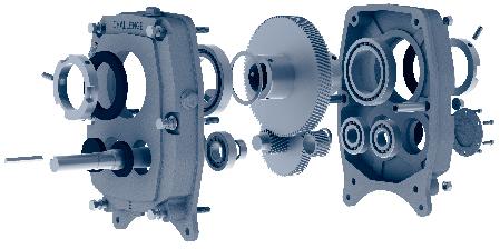
2 s Metric Range Features The Challenge SMSR stands tall amongst the crowd. Packed full of attention to detail, the Challenge SMSR delivers performance in the harshest of applications. Shaft mounted drives remove the need for couplings, mounting plinths and have infinitely variable ratios due to the belt drive. They are also incredibly simple to fit and can be mounted in any position as no motor base is required. Grip-Loc hubs now avaliable for simple installation and removal Includes complete torque arm assembly Interchangeable with most other manufacturers Production line manufacturing guarantees tolerances and consistent quality. Gears produced on German manufactured hobbing centres to achieve the highest quality helical gear components. Pinions; 8620 steel Gears; 20MnCr5 steel All gears are ground Final heat treatment includes gas carburising to a depth of 1mm, then grinding to DIN class 6. Castings crack tested All units test run prior to final quality control checks Full traceability guaranteed with unique Challenge serial number. Backstops also available to prevent reversing ratios exceed 150:1 with a belt drive Double lipped oil seals used throughout Standard ball and cylindrical roller bearings used - in stock around the world 1
3 selection procedure 1] Service Factor. From Table 1 on page 357, select the service factor that is appropriate for the application 2] Design Power. Multiply the absorbed power of the driven machine by the service factor, from step 1) to obtain the design power. If the absorbed power is not known, use the motor power 3] SMSR gear unit size selection. Refer to the power rating Tables on pages 357 and 358 then read down the left hand vertical column to the required output speed. (interpolate if the exact speed is not listed). Read horizontally across on the speed line until a power equal to or in excess of the design power, from step 2), is reached. Read vertically to the top of the column to obtain the correct size of SMSR unit. The ratio of the chosen unit is determined by the required output speed. Go to page 371 or 372 in order to check the chosen SMSR will fit the driven machine shaft. Wedge belt drive selection procedure. Two methods are used for the belt drive selection. One for 1440 rev/min electric motors and secondly for all other speeds rev/min electric motor speed. a] speed. Refer to the Wedge belt drive selection pages (pages 359 to 367) for the chosen gear unit size. Read down the left hand column headed output speed until a speed equal to or near to that required is found. b] Pulley pitch diameters. Read across from the chosen output speed to obtain the pulley diameters for the motor shaft and SMSR input shaft On smaller size gear units, it may well be that single belt drives are recommended. If, on such drives, two belts are preferred, special attention must be made to belt tensioning. If in any doubt, please contact CHALLENGE. c] Centre distance. Refer to page 160 in order to calculate the correct belt length for the required centre distance Other prime mover speeds a] SMSR unit input shaft speed. Multiply the chosen SMSR gear unit output speed by its exact speed ratio to obtain the SMSR gear unit input shaft speed. The exact gear ratio of the chosen SMSR can be found at the bottom of the SMSR dimension Table on page 369 column 2. b] Selection of Wedge belt drive. The correct Wedge belt can be designed by referring to the selection procedure on page 160. selection example Select a CHALLENGE to drive a rotary kiln which absorbs 0.95 kw when running at 20 rev/min for upto 8 hours/day. The prime mover is a 1.1 kw, 1440 rev/min electric motor with a star-delta starter and a 24 mm shaft. The kiln has a 50 mm shaft and 450 mm drive centres are required. ****************************************************************** 1] Service Factor. From Table 1 on page 357, the chosen service factor is ] Design Power. Using the kiln absorbed power of 0.95 kw, the design power is : x 1.25 = 1.19 kw 3] SMSR gear unit size selection. From the SMSR power rating Table on page 358, a size D13 or D20 will transmit 1.58 kw at 20 rev/min which is excess of the required 1.19 kw from step 2). A size D20 rather than a D13 is chosen as it will utilize a more economically priced Wedge belt drive. On checking the hub sizes on page 371, it is seen that the D20 has a 50 mm standard hub bore which matches the kiln shaft of 50 mm. Wedge belt drive selection procedure. As the motor speed is 1440 rev/min, the following selection method is used : rev/min electric motor speed. a] speed. Refer to the drive selection page 361 for SMSR size D units. Read down the left hand column to required output speed of 20 rev/min. b] Pulley pitch diameters. Read across from the chosen output speed to obtain the prime mover and SMSR input shaft pulley diameters. The electric motor to be fitted with a 71 x 1 SPZ pulley and the SMSR input shaft with a 250 x 1 SPZ c] Centre distance. Refer to page 160 and by using the appropriate formulae, an SPZ1420 will give a centre distance of 449 mm. Specification. SMSR size: D20 with a standard hub bore of 50 mm Motor pulley: 71 x 1 SPZ with taper bush size 1108 bored 24 mm SMSR input shaft pulley: 250 x 1 SPZ with taper bush 2012 bored 25 mm An SPZ1420 Wedge belt gives a centre distance of 449 mm. 2
4 Table 1, Service Factors Number of hours per day running Type of driven machine Uniformly loaded applications Agitators and mixers - uniform density, centrifugal blowers, belt conveyors and elevators, non-reversing laundry machines, line shafts, centrifugal and rotary pumps, wire drawing machines under over Moderate shock load applications Agitators and mixers variable density, conveyors medium duty, cranes, feeders pulsating loads, hoists, kiln, other laundry machinery, lifts, piston pumps with 3 or more cylinders, paper making machinery, rubber mixers and calenders, rotary screens, textile machinery Heavy duty machinery Brick making machinery, heavy duty conveyors, crushers, reciprocating feeders, hammer mills, piston pumps with 1 or 2 cylinders, rubber masticators, vibrating machines SMSR Power Rating Table kw ( 5:1) Single Reduction SMSR rev/min B5 C5 D5 E5 F5 G5 H5 J Torque 100 rev/min Note: Challenge do not recommend the use of backstops on 5:1 units as this effects the units power ratings. Should this be necessary please contact the Challenge Technical Department. 3
5 SMSR Power Rating Table kw ( 13:1 & 20:1) SMSR Double Reduction rev/min B13/B20 C13/C20 D13/D20 E13/E20 F13/F20 G13/G20 H13/H20 J13/J20 S 20 K 20 L Torque 10 rev/min Note: The wavy line indicates maximum output speed for 20:1 ratio units, for speeds above this limit use 13:1 or 5:1 ratio units. 4
6 Wedge s for 1440 rev/min Electric Motors B 5:1 Speed Motor Gearbox of s SPZ* SPZ* SPZ* SPZ* SPZ* SPZ* SPZ* SPZ SPZ SPZ SPZ SPZ SPZ* SPZ SPZ SPZ SPZ* SPA* SPA* SPZ SPZ SPZ SPA* SPA SPA* SPZ SPA* SPA SPZ* SPA* SPA* SPZ SPA* SPA* SPA* SPZ SPZ SPZ SPA* SPA* SPA* SPZ SPA* SPZ SPZ* SPZ SPZ SPA* SPA SPZ B 13:1 * Single belt drives can be used, however, two belts can also be used without overloading the SMSR input shaft bearings. Speed Motor Gearbox of s SPZ* SPZ* SPZ* SPZ* SPZ* SPZ* SPZ* SPZ* SPZ* SPZ* SPZ* SPZ* SPZ* SPZ* SPZ* SPZ* SPZ* SPZ* SPZ* SPZ* SPZ* SPZ* SPZ SPZ SPA* SPA* SPA* SPZ* SPZ SPA* SPZ SPA* SPZ* SPZ SPA* SPA* SPA* SPZ SPA* SPA* SPZ SPZ SPA* SPA* SPZ SPA* SPZ SPZ SPA* SPZ B 20:1 Speed Motor Gearbox of s SPZ SPZ SPZ* SPZ SPZ* SPZ* SPZ* SPZ* SPZ* SPZ* SPZ* SPZ* SPZ* SPZ* SPZ* SPZ* SPZ* SPZ* SPZ* SPZ* SPZ* SPZ* SPZ* SPZ* SPZ* SPZ* SPA SPZ* SPZ* SPZ* SPA SPZ* SPZ* SPZ* SPZ* SPA SPZ* SPZ* SPZ* SPZ* SPZ* SPZ* SPZ* SPZ* SPA SPZ* SPZ* SPZ* SPZ SPZ* 5
7 Wedge s for 1440 rev/min Electric Motors C 5:1 Speed Motor Gearbox of s SPZ SPZ SPZ SPA* SPA* SPZ* SPZ SPZ* SPA* SPZ* SPA* SPA* SPA* SPZ SPZ SPZ SPA* SPA* SPA SPA* SPZ SPA SPA SPA SPA* SPZ SPA SPA* SPZ SPA SPA SPA SPZ SPZ SPA* SPA SPZ SPA SPA SPA* SPZ SPZ SPA SPA SPZ SPA SPZ SPZ SPA SPA* C 13:1 * Single belt drives can be used, however, two belts can also be used without overloading the SMSR input shaft bearings. Speed Motor Gearbox of s SPZ* SPZ* SPZ* SPZ* SPZ* SPZ* SPZ* SPZ* SPZ* SPZ* SPZ SPZ* SPZ* SPZ* SPZ SPZ* SPZ SPZ* SPA* SPZ* SPZ SPZ SPA* SPZ SPA* SPA* SPA* SPZ SPA* SPZ SPA* SPA* SPZ SPZ SPZ SPZ SPA* SPZ SPZ SPA* SPZ SPA* SPZ SPZ SPA* SPZ SPA* SPZ SPZ SPA* C 20:1 Speed Motor Gearbox of s SPZ SPZ SPZ* SPZ* SPZ* SPZ* SPZ* SPZ* SPZ* SPZ* SPZ* SPZ* SPZ* SPZ* SPZ* SPZ* SPZ* SPZ* SPZ* SPZ* SPZ SPZ* SPZ* SPZ* SPZ* SPA SPZ* SPZ* SPZ* SPZ* SPA SPA SPZ* SPZ* SPZ SPZ* SPZ SPZ SPZ* SPZ* SPZ SPZ* SPZ SPZ* SPZ SPZ SPZ SPZ SPA SPZ 6
8 Wedge s for 1440 rev/min Electric Motors D 5:1 Speed Motor Gearbox of s SPA* SPZ SPA* SPA* SPA* SPA* SPZ SPZ SPA SPZ SPA* SPZ SPA SPA SPA SPZ SPA SPZ SPA* SPA SPZ SPA* SPA SPA SPZ SPA SPA SPA SPA SPZ SPA SPA SPA SPZ SPA SPA SPA SPA SPA SPZ SPA SPB SPA SPA SPA* SPZ SPZ SPA SPA SPZ D 13:1 * Single belt drives can be used, however, two belts can also be used without overloading the SMSR input shaft bearings. Speed Motor Gearbox of s SPZ SPZ SPZ SPZ* SPZ* SPZ* SPZ* SPZ* SPZ SPZ* SPZ* SPA* SPZ SPZ SPA* SPZ SPZ SPZ SPZ SPZ SPZ SPZ SPZ SPA* SPA* SPA SPZ SPA* SPZ SPA* SPZ SPA* SPZ SPA* SPZ SPZ SPA* SPA SPA SPZ SPA SPA* SPA SPA SPA SPA SPA* SPA SPA SPZ D 20:1 Speed Motor Gearbox of s SPZ SPZ SPZ* SPZ* SPZ* SPZ* SPZ* SPZ* SPZ* SPZ* SPZ* SPZ* SPZ* SPZ* SPZ* SPZ* SPZ SPZ* SPZ* SPZ* SPZ* SPZ SPZ SPZ* SPZ* SPZ SPZ* SPZ SPA* SPZ SPZ* SPZ SPA* SPZ SPZ* SPZ SPZ SPZ SPA* SPZ* SPZ SPA* SPA* SPZ SPZ* SPZ SPA SPZ SPA SPA 7
9 Wedge s for 1440 rev/min Electric Motors E 5:1 Speed Motor Gearbox of s SPZ SPZ SPA SPA* SPA* SPA* SPA SPA SPA SPA SPZ SPA SPZ SPA SPA SPZ SPA SPZ SPZ SPA SPB SPA SPA SPA SPZ SPB SPA SPA SPA SPA SPA SPA SPZ SPB SPA SPA SPA SPZ SPA SPA SPA SPA SPB SPA SPB SPZ SPB SPA SPA SPA E 13:1 * Single belt drives can be used, however, two belts can also be used without overloading the SMSR input shaft bearings. Speed Motor Gearbox of s SPZ SPZ SPZ SPZ SPZ SPZ SPA* SPZ SPZ SPA* SPA* SPA* SPA* SPA* SPZ SPZ SPZ SPA* SPA* SPZ SPZ SPZ SPA SPZ SPA SPA SPA* SPA SPA SPZ SPA SPA SPA SPZ SPA* SPA SPA SPA SPA SPA SPA* SPA SPA SPB SPA SPZ SPA SPA SPZ SPZ E 20:1 Speed Motor Gearbox of s SPZ SPZ SPZ* SPZ* SPZ* SPZ* SPZ* SPZ* SPZ* SPZ* SPZ SPZ* SPZ* SPZ SPZ SPZ SPZ SPZ SPZ SPZ SPZ SPZ SPZ SPZ SPZ SPZ SPA* SPA* SPA* SPZ SPA* SPA* SPA SPA* SPZ SPA* SPZ SPA* SPA* SPZ SPA SPA SPA SPA* SPA SPZ SPZ SPA SPA SPA* 8
10 Wedge s for 1440 rev/min Electric Motors F 5:1 F 13:1 F 20:1 Speed Motor Gearbox of s SPZ SPA SPA SPZ SPA SPB SPB SPZ SPZ SPB SPA SPB SPZ SPB SPZ SPA SPZ SPA SPZ SPA SPB SPA SPB SPA SPB SPZ SPB SPB SPA SPB SPA SPB SPZ SPB SPA SPB SPB SPB SPA SPA SPA SPB SPA SPB SPB SPA SPB SPA SPA SPA * Single belt drives can be used, however, two belts can also be used without overloading the SMSR input shaft bearings. Speed Motor Gearbox of s SPZ SPZ SPZ SPZ SPZ SPA* SPA* SPA* SPZ SPA* SPA* SPA* SPA* SPA* SPA SPA SPA SPA SPB SPZ SPA SPZ SPA* SPA SPA SPA SPA SPZ SPA SPZ SPA SPA SPA SPA SPZ SPZ SPA SPB SPB SPA SPA SPA SPA SPB SPA SPA SPB SPA SPZ SPB Speed Motor Gearbox of s SPZ SPZ SPZ SPZ SPZ SPZ SPZ SPZ SPA* SPA* SPA* SPA* SPZ* SPA* SPZ SPZ* SPA* SPZ SPZ SPZ SPA* SPZ SPZ SPA SPA* SPZ SPZ SPZ SPA SPZ SPZ SPA* SPA SPA SPB SPA SPZ SPA* SPA SPA SPZ SPA SPA SPA SPA SPA SPA SPA SPA SPA 9
11 Wedge s for 1440 rev/min Electric Motors G 5:1 G 13:1 G 20:1 Speed Motor Gearbox of s SPA SPZ SPA SPZ SPA SPZ SPB SPA SPZ SPA SPB SPA SPB SPB SPA SPA SPA SPB SPA SPB SPB SPB SPB SPB SPB SPB SPA SPB SPA SPB SPB SPC SPB SPC SPB SPC SPB SPB SPB SPC SPB SPB SPB SPC SPB SPB SPB SPB SPA SPB * Single belt drives can be used, however, two belts can also be used without overloading the SMSR input shaft bearings. Speed Motor Gearbox of s SPZ SPZ SPZ SPZ SPZ SPZ SPA SPZ SPZ SPZ SPZ SPA SPA SPZ SPZ SPZ SPA SPZ SPA SPA SPA SPA SPZ SPZ SPZ SPA SPA SPA SPZ SPA SPA SPB SPZ SPA SPA SPB SPZ SPA SPB SPA SPB SPA SPA SPB SPA SPB SPA SPA SPB Speed Motor Gearbox of s SPZ SPZ SPZ SPZ SPZ SPZ SPZ SPZ SPZ SPZ SPZ SPA SPZ SPA SPZ SPZ SPA* SPZ SPZ SPA SPZ SPA SPA SPA SPA SPA SPZ SPZ SPA SPA SPA SPZ SPA SPA SPZ SPZ SPA SPA SPA SPA SPA SPA SPA SPA SPB SPA SPA SPA SPB SPB 10
12 Wedge s for 1440 rev/min Electric Motors H 5:1 H 13:1 H 20:1 Speed Motor Gearbox of s SPZ SPB SPA SPA SPA SPA SPB SPA SPB SPB SPA SPB SPB SPB SPB SPC SPA SPC SPB SPB SPB SPB SPC SPA SPC SPB SPB SPC SPB SPB SPC SPC SPB SPC SPB SPC SPB SPB SPC SPC SPB SPC SPB SPC SPA SPB SPB SPC SPB SPB Speed Motor Gearbox of s SPZ SPZ SPZ SPZ SPZ SPZ SPA SPA SPA SPA SPZ SPZ SPA SPA SPA SPZ SPA SPZ SPA SPA SPB SPA SPB SPZ SPB SPA SPB SPB SPA SPB SPA SPB SPB SPB SPB SPB SPA SPB SPB SPA SPA SPB SPB SPA SPB Speed Motor Gearbox of s SPZ SPZ SPZ SPZ SPA SPZ SPZ SPA SPZ SPA SPA SPA SPA SPA SPA SPA SPA SPZ SPZ SPA SPZ SPZ SPA SPA SPA SPA SPA SPB SPZ SPA SPA SPA SPZ SPA SPA SPB SPA SPB SPA SPA SPB SPA SPB SPA SPB 11
13 Wedge s for 1440 rev/min Electric Motors J 5:1 Speed Motor Gearbox of s SPB SPB SPB SPB SPA SPB SPA SPB SPB SPB SPB SPB SPB SPB SPB SPC SPC SPC SPB SPC SPC SPC SPC SPC SPC SPC SPC SPC SPC SPC SPB SPC SPC SPC SPC SPC SPC SPC SPC SPC SPC SPC SPC SPC SPC SPC SPC SPC SPC SPC J 13:1 Speed Motor Gearbox of s SPA SPZ SPA SPA SPA SPZ SPZ SPA SPA SPZ SPA SPA SPZ SPA SPB SPB SPA SPA SPA SPA SPA SPA SPB SPB SPA SPB SPB SPB SPC SPB SPA SPB SPC SPB SPA SPA SPB SPA SPB SPB SPB SPB SPA SPB SPB SPB SPB SPB SPB SPB J 20:1 Speed Motor Gearbox of s SPZ SPZ SPA SPZ SPA SPA SPA SPZ SPA SPA SPZ SPA SPA SPA SPB SPA SPA SPB SPZ SPB SPZ SPB SPA SPB SPC SPA SPC SPB SPA SPA SPC SPA SPB SPA SPA SPB SPB SPA SPB SPA SPB SPA SPA SPB SPB SPB SPA SPB SPB SPB 12

14 Wedge s for 1440 rev/min Electric Motors S 20:1 K 20:1 L 20:1 Speed Motor Gearbox of s SPA SPA SPA SPA SPA SPA SPB SPA SPB SPB SPA SPB SPB SPB SPB SPB SPB SPC SPB SPC SPC SPC Speed Motor Gearbox of s SPB SPA SPB SPB SPB SPB SPB SPB SPB SPB SPB SPB SPB SPC SPC SPC SPC SPC SPC SPC SPC SPC Speed Motor Gearbox of s SPB SPB SPB SPB SPB SPB SPC SPC SPB SPB SPB SPB SPC SPC SPC SPC SPC SPC SPC SPC SPC SPC 13

15 SMSR Dimensions A T G H G W V U Y F B E 90 o C X D L J M 90 o K K P Q R O N R S Note: for flange mounting positions-consult CHALLENGE 14
16 SMSR Dimensions Table SMSR Dimensions B C D E F G H J S K L A B hub key 8 x 7 12 x 8 14 x 9 16 x x x x x x x x 20 C D E F Input shaft keyway 6x3.5x50 6x3.5x59 8x4x63 8x4x70 10x5x70 12x5x90 14x5.5x95 16x6x100 16x6x100 18x7x110 18x7x110 G H J K L M N O P M16 M24 Q R S Min Max T U V W X Y Weight-kgf single reduction double reduction Exact Gear s Nominal 5: s 13: :
17 Motor Mount Dimensions B A C D Motor Mount Dimensions (mm) A Min Max B C D Accommodates Metric Motor Frame B a 80b 90S 90L C L 90S 90L 100L D S 90L 100La 100Lb 112M E S 90L 100L 112M F S 100La 100Lb 112M 132S 132M G S 90L 100L 112M 132S 132M 160M 160L H L 100L 112M 132S 132M 160M 160L 180M 180L J L 112M 132S 132M 160M 160L 180M 180L 200L It is recommended that the SMSR should be mounted independently if a larger motor frame size, than those listed above, be required for any particular SMSR size. A Max this distance must include belt tensioning allowances. A Min this distance must include belt fitting allowances. NOTE: It is recommended that a V belt guard be fitted to the assembly 16

 Bores SMSR bore Reducing bush bores B 40 35, 32 C 50")


18 Hubs Standard hub bores are machined to F7 limits and a h7 tolerance is recommended for the shaft. Standard Hub Bores SMSR bore Reducing bush bores B C 40 35, 32, 30 D 50 45, 42, 40, 38 E 55 50, 45, 42 F 65 60, 55, 50 G 75 70, 65, 60 H 85 80, 75, 70 J , 90 S , 100, 90 K , 100, 90 L , 125, 100 Alternative Hub (Maximum) Bores SMSR bore Reducing bush bores B 40 35, 32 C 50 45, 42, 38 D 55 - E F G H , 90 J Hub Keyways Keyways for standard output hubs and reducing bushes are machined to BS The shaft keyway should be machined in accordance with the Table below. Shaft ø Key Shaft ø Key Shaft ø Key Shaft ø Key 30 8 x x x x x x x x x x x x x x x x x x x x x x x x 20 Challenge Reducing Bush Locking System Keys are supplied when reduction bushes are used. Usually two keys are supplied, but for thin walled bushes, a single stepped key will be supplied. Shaft SMSR Standard Hollow Shaft Plain Reducing Bush Grub Screw(s) Keyed Reducing Bush Key Step 1: Insert the keyed and plain reducing bushes into the hollow shaft. Step 2: Mount gearbox with reducing bushes onto the driven shaft and insert key. Step 3: Tighten grub screws on collar sequentially 17

 Screw Grip-Loc Bush (clockwise)")
 Tighten cap head screws sequentially (which draws the bush against its opposing taper and locks solid against the shaft).")


19 Hubs Challenge Grip-Loc Locking System Shaft SMSR Grip-Loc Hub Locking Plate Grip-Loc Bush Screws Advantages Has sufficient torque transmitting ability to avoid the need for conventional shaft keys Reversible assembly Obviates problems caused by the usual operating environment and atmospheric conditions By virtue of the design, Grip-Loc prevents the onset of fretting corrosion, which often causes problems with more conventional mounting systems Much more simple to install and remove than keyed assemblies Fits standard shafts with h11 tolerances Procedure for Assembly 1) Screw Grip-Loc Bush (clockwise) into Grip-Loc Hub. 2) Mount on driven shaft to the required position. 3) Tighten cap head screws sequentially (which draws the bush against its opposing taper and locks solid against the shaft). Grip-Loc Hub Bores SMSR Bore B 30 C 40 D 50 E 55 F 65 G 76 H 85 J 100 S 120 K 125 L Procedure for Removal This is a much simpler operation compared to the hollow shaft speed reducers that utilise parallel keys. Many applications are subject to poor operating conditions, such as in quarries etc. When the time comes to remove the SMSR from the shaft, a build up of corrosion can become a major problem and make the disassembly difficult. As the Grip-Loc hub and shaft are of dissimilar metals, fretting corrosion is not a problem. Therefore, when the Grip-Loc screws are loosened and the tapers part, sufficient clearance is created for the Grip-Loc bush and speed reducer to be easily removed from the shaft. Safety Once a Grip-Loc hub has been correctly installed, there is no possibility for the taper to break and thus allow the speed reducer to move on the shaft. The installation and removal screws play no part in holding the taper grip and even their removal would not adversely affect the performance of Grip-Loc. 18

20 SMSR Installation Satisfactory performance depends on correct installation, lubrication and maintenance. Therefore it is important that the instructions in the installation leaflet are followed carefully. 1. Prepare driven shaft by removing key and ensuring surface is clean, smooth and free from burrs. Coat shaft with Anti Seize Compound. Reduce gap to minimum 2. Align reducer hub and shaft keyway then gently slide the reducer on to the driven shaft. Mount the reducer as close to driven shaft bearing as possible to reduce the overhung load. If possible the end of the driven shaft should be level with the outer edge of reducer output hub. 3. Fit the drive key to protrude at least one third way into length of hub keyway and flush with outer edge of reducer hub. 4. The hub clamp can now be tightened. Reduce gap to minimum The Challenge SMSR creates little, if any, axial load on the shaft necessitating only light clamping to locate the unit on to the driven shaft. 5. Install pulley on gearbox input shaft as close to the reducer as possible. Failure to do this will cause excessive loads in the input shaft bearings and could cause their premature failure. 6. Install motor and belt drive with the belt pull at approximately 90 to the centre line between driven and input shafts. This will permit tensioning of the belt drive with the torque arm. The torque arm itself should work in tension. If output hub runs anti-clockwise, the torque arm should be positioned to the right. 7. Install torque-arm fulcrum on a rigid support so that the torque arm will be at approximately right angles to the centre line through the driven shaft and the torque-arm case bolt. 8. Make sure there is sufficient take up in the turn-buckle for belt tension adjustment. The torque arm can be positioned to the right or left. 90 o Position torque arm at 90. A 15 tolerance either way is allowed For clockwise rotation position the belt drive and torque arm to that shown. 90 o The belt drive can be positioned to the right or left. 19
21 Lubrication Units are supplied without oil and should be filled before running with a recommended lubricant to the correct level dependant on the mounting position. Mounting Position3 Remove the taper plugs from the filler/breather and level positions as shown in the diagram. Fill until the lubricant overflows the oil level aperture. Replace the level taper plug. For output speeds below 10 rev/min, consult Challenge. Mounting Position4 Fit the filler/breather plug (supplied loose). Synthetic Lubricants Certain approved synthetic lubricants are suitable for use in gear units - consult your lubricant supplier Recommended oil change periods The first change should be after 2500 hours and thereafter every 8000 hours of running or two years. If the temperature exceeds 70 C, then oil changes should be every 6 months. If the application is subject to frequent stops/starts, oil changes should be more frequent. It is also recommended that the breather plug should be changed with every oil change. Mounting Position2 Mounting Position1 Fill Point Level Check Drain Point Units are supplied without oil and should be filled before operation Lubricant Capacity SMSR Capacity (Litres) 5:1 13:1 & 20:1 Mounting Position Mounting Position B C D E F G H J S K L Mineral Oil ISO Viscosity Grade Unit 5:1 13:1 & 20:1 rev/min SMSR BCDE BCDE BCDEF BC DEFGHJ Amb Temp C FGHJ FGHJ GHJS BCD EFGHJS BCD EFGHJS K L K L -10 to to to Note: Do not use Extreme Pressure (E.P.) mineral oils when using a backstop. 20


22 Backstops Note: Challenge do not recommend the use of backstops on 5:1 units as this effects the units power ratings. Should this be necessary please contact the Challenge Technical Department. Installation If the reducer is filled with oil, drain off the oil before proceeding. Step 1: Remove the backstop cover and gasket from the reducer body. Step 2: Determine the required direction of shaft rotation. B, C, D, E, F backstops: arrow mark on backstop These sizes do not have an inner race, the rotation arrow is marked on the outer race. The shaft s free direction is opposite to the arrow. G, H, J, S, K, L backstops: arrow mark on backstop These sizes have an inner race, the rotation arrow is marked on the outer race. The inner race s free direction is opposite to the arrow. Locate the backstop into the housing. Feed the key into the backstop outer race and housing keyways. In the case of backstops with an inner race, feed another key into the backstop s inner race and the shaft keyways and install the circlips on the shaft groove. If you require the shaft to rotate in the opposite direction, turnthe backstop around so that the side which has arrow faces the reducer. Step 3: Install the backstop cover with a new gasket Step 4: Refill the reducer with the correct quantity and grade of oil. CAUTION: When pressing the backstop into the housing, do NOT use a hammer. The backstop may be tapped gently if necessary with a soft mallet. 21
23 Maintenance Parts Product Codes 22
24 Maintenance Parts Product Codes drawing number description if required # can be positioned to suit number required B C D E F G H J S K L 1 Case (right hand) 1 B6002 C6002 D6002 E6002 F6002 G6002 H6002 J6002 S6002 K6002 L Case (left hand) 1 B6003 C6003 D6003 E6003 F6003 G6003 H6003 J6003 S6003 K6003 L Hollow dowel 2 B7004 C7004 D7004 E7004 F7004 G7004 H7004 J7004 S7004 K7004 L Case bolt 6 B C D E F G H J S K L Case nut 6 B C D E F G H J S K L Case plain washer 4 B C D E F G H J S K L Case lock washer 6 B C D E F G H J S K L Torque arm case bolt H J S K L Torque arm case bolt nut H J S K L Torque arm case bolt lock washer H J S K L Input shaft and pinion (5:1) * 1 B6128 C6120 D6120 E6128 F6120 G6120 H6120 J6120 S6120 K6120 L Input shaft and pinion (13:1) 1 B6108 C6100 D6100 E6109 F6100 G6100 H6100 J6100 S6100 K6100 L Input shaft and pinion (20:1) 1 B6118 C6110 D6110 E6119 F6110 G6110 H6110 J6110 S6110 K6110 L Input shaft bearing-shaft side 1 BNJ204EC CNJ205EC DNJ206EC ENJ306EC FNJ307EC GNJ309EC HNJ310EC JNJ312EC SNJ312EC KNJ312EC LNJ312EC 22 Input shaft bearing-backtop side 1 B6303 C6205 D6206 E6306 F6307 G6309 H6310 J6312 S6312 K6312 L Input shaft oil seal 1 B C D E F G H J S K L Input shaft spacer 1 B6050 C6050 D6050 E6050 F6050 G6050 H6050 J6050 S6050 K6050 L Backstop 1 B-B.Stop C-B.Stop D-B.Stop E-B.Stop F-B.Stop G-B.Stop H-B.Stop J-B.Stop S-B.Stop K-B.Stop L-B.Stop 26 Backstop cover 1 B7012 C7012 D7012 E7012 F6012 G6012 H6012 J6012 S6012 K6012 L Backstop cover gasket 1 B7013 C7013 D7013 E7013 F7013 G7013 H7013 J7013 S7013 K7013 L Backstop cover screw 6 B C D E F G H J S K L Backstop cover lockwasher 6 B C D E F G H J S K L st reduction gear (13:1) 1 B6101 C6101 D6101 E6101 F6101 G6101 H6101 J6101 S6101 K6101 L st reduction gear (20:1) 1 B6111 C6111 D6111 E6111 F6111 G6111 H6111 J6111 S6111 K6111 L st reduction gear key 1 B7021 C7021 D7021 E7021 F7021 G7021 H7021 J7021 S7021 K7021 L Intermediate pinion (13:1 & 20:1) 1 B6022 C6022 D6022 E6022 F6022 G H6022 J6022 S6022 K6022 L Intermediate pinion distance piece 1 B6023 C6023 D6023 E6023 F6023 G6023 H6023 J6023 S6023 K6023 L Intermediate bearing (13:1, 20:1) 2 B6303 C6205 D6206 E6306 F6307 G6309 H6310 J6312 S6312 K6312 L Intermediate cover 2 B7025 C7025 D7025 E7025 F7025 G7025 H7025 J7025 S7025 K7025 L hub (standard hub bore) 1 B6105 C6105 D6105 E6105 F6105 G6105 H6105 J6105 S6105 K6105 L hub (alternative hub bore-upper) 1 B6106 C6106 D6106 E6106 F6106 G6106 H6106 J6106 S6106 K6106 L hub spacer 1 B6030 C6030 D6030 E6030 F6030 G6030 H6030 J S K L hub collar 2 B6031 C6031 D6031 E6031 F6031 G6031 H6031 J6031 S6031 K6031 L hub circlip 2 B C D E F G Collar screw (standard hub) over key 1 B C D E F G H J S K L Collar screw (standard hub) over shaft 1 B C D E F G H J S K L Collar screw (alternative hub-upper) over key 1 B C D E F G H J S K L Collar screw (alternative hub-upper) over shaft 1 B C D E F G H J S K L hub bearing 2 B6011 C6013 D6015 E6017 F6020 G6022 H6026 J6030 S6030 K6030 L hub oilseal 2 B C D E F G H J S K L hub reduction gear 1 B6026 C6026 D6026 E6026 F6026 G6026 H J6026 S6026 K6026 L hub reduction gear key 1 B6027 C6027 D6027 E6027 F6027 G6027 H6027 J6027 S6027 K6027 L Pipe plug 4# B C D E F G H J S K L Breather plug 1# B C D E F G H J S K L Torque arm rod end 1 B7041 C7041 D7041 E7041 F7041 G7041 H7041 J7041 S7041 K7041 L Torque arm rod end locknut 1 B C D E F G H J S K L Torque arm extension 1 B7043 C7043 D7043 E7043 F7043 G7043 H7043 J7043 S7043 K7043 L Torque arm extension locknut 1 B C D E F G H J S K L Turnbuckle 1 B7045 C7045 D7045 E7045 F7045 G7045 H7045 J7045 S7045 K7045 L Fulcrum 1 B6046 C6046 D6046 E6046 F6046 G6046 H6046 J6046 S6046 K6046 L Torque arm fulcrum bolt 1 B C D E F G H J S K L Torque arm fulcrum bolt nut 1 B C D E F G H J S K L Torque arm fulcrum bolt lockwasher 1 B C D E F G H J S K L Note: Challenge do not recommend the use of backstops on 5:1 units as this effects the units power ratings. Should this be necessary please contact the Challenge Technical Department. 23


25 s TXT Range Features Challenge TXT range of s are inch in design for America and other imperial dimension countries. Challenge TXT gear units are manufactured in eight gear case sizes, from size 2 to size 9, maximum power up to 150hp, nominal gear ratios are 15:1 and 25:1. A wide choice of final driven speeds can be determined by the use of an appropriate input belt drive. The units will normally be oil lubricated, but they are equally suitable for long life synthetic lubricants. 1. Twin Tapered Hub A tapered bore in both sides of the reducer s output hub snugs up against a matching taper on the outer surface of the bushing. Bushing mounting screws pass through the bushing flange into a mounting collar on the hub. As the screws are tightened, the bushing moves inward, gripping the driven machine s input shaft tightly and evenly around every point on its circumference. It is easy-on, easy-off. All of the output bushing bores accord to ANSI standards. Also available are ISO standard straight bore output hubs. 2. Precision High Quality Gearing Computer designed helical gears, strong alloy materials for high load capacity, case carburized for long life, ground profile, crown tooth profile, in conformance with ISO % efficiency per stage, smooth quiet operation with several teeth in mesh. 3. Power Ratings All TXT SMSR s have power ratings to ISO standards. 4. Maximum Capacity Housing Design Close grain cast iron construction. Excellent vibration dampening and shock resistance features. Precision bored and dowelled to ensure accurate in-line assembly. 5. Strong Alloy Steel Shafts Strong alloy steel, hardened, ground on journals, gear seatings and extensions, for maximum load and maximum torsional loads. Generous size shaft keys for shock loading. 6. Using an adapter for mounting the torque arm increases the strength of the gear case. The torque arm is easy-on and easy-off for reliability and controls the position of the standard torque arm mounting within recommended limits. 7. BackStops As an optional part, anti-run back devices are available. 8. Bearing and Oilseals Bearings are all tapered roller (except TXT2), having long life service time. Oilseals are double lipped garter spring type, ensuring effective oil sealing. 9. Torque Arm Assembly For easy adjustment of the belt.
26 TXT Speed Reducer Selection Procedure The selection tables for Challenge TXT Shaft Mounted Reducers are for electric motor selections up to 150hp with output speeds up to 400 using AGMA recommended application class numbers. For extreme shock or high energy loads which must be absorbed, as when stalling; for power source other than an electric motor; or for extreme ambient temperatures, or oversized equipment, consult Challenge. Step 1: Determine Class of Service - See table 1, page 381 to 383, to determine the Load Classification for applications under normal conditions. Find the type application and duty cycle that most closely matches your specific application. Class I Steady loads not exceeding motor hp rating and light shock loads operating up to 10 hours a day. Moderate shock loads are allowable if the operation is intermittent. For Class I applications, the maximum value of starting and momentary peak loads should not exceed 2 x motor hp rating. If it exceeds this amount it should be divided by 2 and the result used in the selection table instead of the motor hp rating. Class II Steady load not exceeding motor hp rating for over 10 hours a day. Moderate shock loads are allowable for up to 10 hours a day. For Class II applications, the maximum value of starting and momentary peak loads should not exceed 2.8 x motor hp rating. If it exceeds this amount it should be divided by 2.8 and the result used in the selection table instead of the motor hp rating. Class III Moderate shock loads for over 10 hours a day. Heavy shock loads are allowable up to 10 hours a day. For Class III applications, the maximum value of starting and momentary peak loads should not exceed 4 x motor hp rating. It exceeds this amount it should be divided by 4 and the result used in the selection table instead of the motor hp rating. Step 2: Determine Reducer - See the selection tables, pages 384 through 386. From selection tables class I, II or III read the reducer size for the application horsepower and output speed. Note: For applications where fan cooling is unacceptable, use the selection tables with an increased class number. Where more than one reducer selection is listed, the most economical ratio is generally listed first. See table 11, page 400 for maximum input and output speeds. Step 3: Compare Hollow Shaft Bore of the TXT425 with the size of the driven shaft. All Challenge taper bushed Shaft Mount Reducers require bushings. Refer to reducer page 396 table 7 for available bushings. If the driven shaft is larger than the bore of the selected reducer, the shaft must be machined to the proper size, or select a larger reducer. Check driven shaft and key for strength. Step 4: Check Dimensions - See table 5, page 395 for reducer dimensions, table 11, page 400 for reducer weights and actual ratio. See page 397 for reducer mounting positions. Step 5: Select a Arrangement - From the s tables, page 387 to 394, select the required sheave ratio for the belt drive. Be careful to select the belt drive so that the sheave mounted on the reducer shaft is not smaller than the minimum sheave diameter with table 14 page 400. Note: Mount the sheave as close as possible to the reducer to minimize the effect of the overhung load on the reducer. Note: For different bore diameters, bushings must be ordered separately, Backstops also need to be ordered separately. Torque arm and adapter are standard parts for the reducer. Each reducer unit is dispatched with them. Selection Example A 10 hp 1750 motor is used to drive an uniformly loaded belt conveyor moving sand, operating 16 hours a day. Head pulley shaft diameter is 2.7/16 and rotates at 70. The driven conveyor cannot be allowed to move backwards. Step 1: Determine Class of Service - From page 381 table 1, locate belt conveyors, uniformly loaded or fed for over 10 hours per day. This load is classified as a Class II application. Step 2: Determine Reducer - From table 3 - Class II Application, page 385, find the column for 10 hp and read down to 70. A TXT 425 reducer is the correct selection. Step 3: Compare Hollow Shaft Bore of TXT 425 with the application driven shaft diameter, page 396, 2.7/16 is the maximum bore available for this size reducer, so it will work on this application. Be sure to check the driven shaft and key strength. Step 4: Check Dimensions and Weights - See page 395, for reducer dimensions, table 11, page 400 for reducer weights and actual ratio, etc. See page 397 for information on mounting positions. Step 5: Select a Arrangement - From the table page 389, read down for 70, find the V- drive ratio of diameter of driver is 6.20, the driven is 6.40, belt size is B, belt number is 3. From table 14, page 400, the TXT 425 s minimum sheave diameter is 4.60, so the selection is correct. Step 6: The reducer cannot be allowed to move backwards, so the backstop assembly must be ordered. Note: when you need to assembly the backstop on the reducer, please specify the output rotation direction when you order. For example, from the input side, the output hub rotates clockwise. 26
27 Application Classification Geared s Table 1 Application Classification and Class Numbers Application 3 to 10 Hrs per Day Class Numbers Over 10 Hrs per Day Agitators (Mixers) Pure Liquids I II Liquids and Solids II II Liquids-Variable Density II II Blowers Centrifugal I II Lobe II II Vane II II Brewing and Distilling Bottling Machinery I II Brew Kettles-Continuous Duty II II Cookers-Continuous Duty II II Mash Tubs-Continuous Duty II II Scale Hopper-Frequent Starts II II Can Filling Machines I II Car Dumpers III III Car Pullers II II Clarifiers I II Classifiers II II Clay Working Machinery Brick Press III III Briquette Machine III III Pug Mill II II Compactors III+ III+ Compressors Centrifugal I II Lobe II II Reciprocating, Multi-Cylinder II III Reciprocating, Single-Cylinder III III Conveyors (Includes Apron, Assembly,, Bucket, Chain, Flight, Oven and Screw) Uniformly Loaded or Fed I II Heavy Duty-Not Uniformly Fed II II Severe Duty-Reciprocating or Shaker III III Cranes III+ III+ Crusher Stone or Ore III III Dredges Cable Reels II II Conveyors II II Cutter Head s III III Pumps III III Screen s III III Class Numbers Application 3 to 10 Hrs per Day Over 10 Hrs per Day Stackers II II Winches II II Elevators Bucket II II Centrifugal Discharge I II Escalators I II Freight II II Gravity Discharge I II Extruders General II II Plastics Variable Speed III III Fixed Speed III III Rubber Continous Screw Operation III III Intermittent Screw Operation III III Fans Centrifugal I II Forced Draft II II Induced Draft II II Industrial & Mine II II Feeders Apron II II II II Disc I II Reciprocating III III Screw II II Food Industry Cereal Cooker I II Dough Mixer II II Meat Grinder II II Slicers II II Generators and Exciters II II Hammer Mills II II Hoists III+ III+ Laundry Tumblers II II Laundry Washers II II Lumber Industry Bakers Spindle Feed II II Main III III Conveyors III+ Large service factor needed, consult Challenge for more information on class number. 27
28 Application Classification Table 1 Application Classification and Class Numbers (continued) Class Numbers Application 3 to 10 Hrs per Day Over 10 Hrs per Day Burner II II Main or Heavy Duty II II Main Log III III Re-saw, Merry-Go-Round II II Slab III III Transfer II II Chains Floor II II Green II III Cut-Off Saws Chain II III Drag II III Debarking Drums III III Feeds Edger II II Gang III III Trimmer II II Log Deck III III Log Hauls-Incline-Well Type III III Log Tuning Devices III III Planer Feed II II Planer Tilting Hoists II II Rolls-Live-off brg.-roll Cases III III Sorting Table II II Triple Hoist II II Transfers Chain II III Craneway II III Tray s II II Veneer Lathe s II II Metal Mills Draw bench Carriage and Main II II Runout Table Non-Reversing-Group s II II Non-Reversing-Individual s III III Reversing s III III Slab Pushers II II Shears III III Wire Drawing II II Wire Winding Machine II II Metal Strip Processing Machinery Bridles II II Class Numbers Application 3 to 10 Hrs per Day Over 10 Hrs per Day Coilers & Uncoilers I II Edge Trimmers II II Flatteners II II Loopers (Accumulators) I I Pinch Rolls II II Scrap Choppers II II Shears III III Slitters II II Mills. Rotary Type Ball & Rod Spur Ring Gear III III Helical Ring Gear II II Direct Connected III III Cement Kilns II II Dryers & Coolers II II Mixers Cement II II Paper Mills Agitators (Mixers) II II Agitators for Pure Liquors II II Barking Drums III III Barkers-Mechanical III III Beater II II Breaker Stack II II Chipper III III Chip Feeder II II Coating Rolls II II Conveyors Chip, Bark, Chemical II II Log (including Slab) III III Couch Rolls II II Cutter III III Cylinder Molds II II Embosser II II Extruder II II Fourdrinier Rolls (includes Lump breaker, dandy roll, wire tuning, and return rolls) Jordan II II Kiln II II Mt. Hope Roll II II Paper Rolls II II Platter II II Presses-Felt & Suction II II II II 28
29 Application Classification Geared s Table 1 Application Classification and Class Numbers (continued) Class Numbers Application 3 to 10 Hrs per Day Over 10 Hrs per Day Pulper III III Pump-Vacuum II II Reel (Surface Type) II II Screens Chip II II Rotary II II Vibrating III III Press II II Thickener (AC Motor) II II Thickener (DC Motor) II II Washer (AC Motor) II II Washer (DC Motor) II II Wind and Unwind Stand I I Winders (Surface Type) II II Plastics Industry-Secondary Processing Blow Molders II II Coating II II Film II II Pipe II II Pre-Plasticizers II II Rods II II Sheet II II Tubing II II Pullers-Barge Haul II II Pumps Centrifugal I II Proportioning II II Reciprocating Single Acting, 3 or more cylinders II II Double Acting, 2 or more cylinders II II Rotary Gear Type I II Lobe I II Vane I II Rubber and Plastics Industry Intensive Internal Mixers Batch Mixers III III Continous Mixers II II Mixing Mill 2 smooth rolls II II 2 corrugated rolls III III Batch Drop Mill-2 smooth rolls II II Application 3 to 10 Hrs per Day Class Numbers Over 10 Hrs per Day Cracker Warmer - 2 roll, 1 corrugated roll III III Cracker - 2 corrugated rolls III III Holding, Feed & Blend Mill-2 rolls II II Refiners-2 rolls II II Calenders II II Sand Muller II II Sewage Disposal Equipment Bar Screens II II Chemical Feeders II II Dewatering Screens II II Scum Breakers II II Slow or Rapid Mixers II II Sludge Collectors II II Thickener II II Vacuum Filters II II Screens Air Washing I II Rotary-Stone or Gravel II II Traveling Water Intake I I Screw Conveyors Uniformly Loaded or Fed I II Heavy Duty II II Sugar Industry Beet Slicer III III Cane Knives II II Crushers II II Mills (low speed end) III III Textile Industry Batches II II Calenders II II Cards II II Dry Cans II II Dyeing Machinery II II Looms II II Mangles II II Nappers II II Pads II II Stashers II II Soapers II II Spinners II II Tenter Frames II II Washers II II Winders II II 29
30 TXT Power Ratings Table 2 Class I Selection Table for TXT SMSR s Rating HP Reducer Selection 1/2 4~ /4 4~ ~ ~ ~ ~ /2 5~ ~ ~ ~ ~ ~ ~ ~ ~ ~ ~ ~ ~ ~ ~ ~ ~ ~ ~ ~ ~ ~ ~ ~ /2 27~ ~ ~ ~ ~ ~ ~ ~ ~ ~ ~ ~ ~ ~ ~ ~ ~ ~ ~ Rating HP Reducer Selection 57~ ~ ~ ~ ~ ~ ~ ~ ~ ~ ~ ~ ~ * 11~ ~ ~ ~ ~70 525* 515* 71~80 515* 525* 81~ * 102~ * 14~ ~ ~ ~ ~ ~ * 19~ ~ ~ ~ ~81 615* 625* 812~ * 115~ * 23~ ~ ~ ~ ~ * 28~ ~ ~70 725* 715* 71~ * 35~ ~ ~78 815* 79~ * ~69 926* 915* 70~ * 60~70 915* 926* ~90 915* 91~ * ~ * Fan cooling required. 30
31 TXT Power Ratings Geared s Table 3 Class II Selection Table for TXT SMSR s Rating HP Reducer Selection 1/3 4~ /2 4~ ~ ~ /4 6~ ~ ~ ~ ~ ~ /2 7~ ~ ~ ~ ~ ~ ~ ~ ~ ~ ~ ~ ~ ~ ~ ~ ~ ~ ~ ~ ~ ~ ~ ~ ~ ~ /2 22~ ~ ~ ~ ~ ~ ~ ~ ~ ~ ~ ~ ~ ~ Rating HP Reducer Selection 10~ ~ ~ ~ ~ ~ ~ ~ ~ ~ ~ ~ ~ ~ * 118~ * 16~ ~ ~ ~ ~ ~ * 20~ ~ ~ ~ ~ ~ * 26~ ~ ~ ~ ~ * 33~ ~ ~ ~ * 40~ ~ ~ ~ ~ * 50~ ~ ~ * 68~75 915* 926* ~ * 104~ * ~ * * Fan cooling required. 31
32 TXT Power Ratings Table 4 Class III Selection Table for TXT SMSR s Rating HP Reducer Selection 1/4 4~ /3 5~ ~ /2 6~ ~ /4 5~ ~ ~ ~ ~ ~ ~ ~ ~ /2 11~ ~ ~ ~ ~ ~ ~ ~ ~ ~ ~ ~ ~ ~ ~ ~ ~ ~ ~ ~ ~ ~ ~ ~ ~ ~ ~ ~ /2 14~ ~ ~ Rating HP 7-1/ Reducer Selection 57~ ~ ~ ~ ~ ~ ~ ~ ~ ~ ~ ~ ~ ~ ~ ~ ~ ~ ~ ~ ~ ~ ~ * 23~ ~ ~ ~ ~ ~ * 28~ ~ ~ ~ ~ ~ ~ ~ ~ ~ * 47~ ~ ~ ~ * 57~ ~ ~ ~75 915* 926* 76~ * * Fan cooling required. 32
33 s for 1750 motors TXT 215 n by 1750 Motors V A V B A V V B A V A A V A A V A A V B A V V B A V V A A A A B A V V V V B A V A A A V B A V V A A V A V A A V V B A A V V A A A V V B B B V V B B A V V B B A A V V B B A B V V B A V V B B B B B V V B B B A V B B V V A A V A B V B B V V B B V B B B A V V V B TXT 225 n by 1750 Motors V B V V A V A V V B V A A V A B V B V V A V V B A V A B V B A V V B A V A B V V A B V V A V V B A V V B V B A V A V A B V V V B A V V B A B V V V V A B A B V V A V V A V B A B B V V B A V V B A B V B V V A V A V V B V V A B A V V A A B V V B V B V B All All dimensions in millimetres in inches unless otherwise stated. 33
34 s for 1750 motors TXT 315 n by 1750 Motors V V V B V V V B A B V V A A A B V A V V A B A V V A A V V A A V V B A V V B A B B B A V V V A B V V A B V B B V A B V A B V V A A B V V A A A V V B V B B V A B V B A V V B A A V B B V V A A V V B B A B V V B B A V V B B A V V B V A B V B B A V V B V B B V A A TXT 325 n by 1750 Motors V B V V V V A B A V V B V A A V A B V V V V A B V V A B A B V V V B A V V V A B V B A V A B V V A B V V V V A B A B V V A B V V V V A B B B V V V B A B A V V B V B B V A B V A B V V V B B V B B V V B B V B B V B V V B B B B V V V B B V B B V A V All dimensions in millimetres inches unless unless otherwise otherwise stated. stated. 34
35 s for 1750 motors TXT 415 n by 1750 Motors V V V A V B V V V V V B A V A B V B A V A B V B V V A B A V V B A B A B A V V B A B V V A B A V V B B B A V V B B B V V B V V B A B V V A B A V B B V C A V V B B V A B V B B B A V B C V V B B V B B V V B B B B V V B V V B B B V B B V B B B B V V B B B B V B B TXT 425 n by 1750 Motors V B V B V V V V A A V B A V A B V V V B A B A V V V V B A B V V A B V V A V B B V V V B B B A V V B B V V B A V V V V B A V B B V V V B B V V B B B A B V V A B V B V B A B V V B V V B B B V V B B B V V B B B V V B B V B B V V A B V V B V B A B V All All dimensions in millimetres in inches unless otherwise stated. 35
36 s for 1750 motors TXT 515 n by 1750 Motors V A B V V B V V V B B V V B A B V V A B A B V V V B B A A V V B A B V V B B A B V V V B A V V V A B B V V A B V B B A V A B V A B V V B A V B B V V B B V B B V B B B V B B B V V B B C V B B V B V B C V V B B A B V V B V B B B C B V V C B V V B B V V C B V B B TXT 525 n by 1750 Motors V B V B A V V B A V A V V B A B A V V V V B A V V B V B A V V B A V V B B B A V V B A V V V A B V B B B V V B B V V A V V C V B A V B B B B V V B C V B B V A B B B V V B B V B V V B V A B B B V V B B V B V V B B V B V B B V V All dimensions in millimetres inches unless unless otherwise otherwise stated. stated. 36
37 s for 1750 motors TXT 615 n by 1750 Motors V A V V V B V A B V V B B B B V B B B V V V B B B B V V B A A B V V B V V B B V V B B A B B V V A B B V V B V V B V B A V B B V B V B C B V B B V A V B B V V V B B V V B C B V C C V V B C B V V B B B V V B V C C V V B B V C B B V C B V B C B V V C B V V C B V V V C B B V V V B B B V V C B C V V B B TXT 625 n by 1750 Motors V V B V V V V B A V V B A B A V V V A B V B A B V V A V V B B V V B A V A B V V B B B V V B V V V C B V B B V V B V V B B B V V B B B V V B B C V V V B B V B B V B V B V B B V B V V B V B B V V B V B V B V B B V V B V B V B All All dimensions in millimetres in inches unless otherwise stated. 37
38 s for 1750 motors TXT 715 n by 1750 Motors V B V C B V V C B V V C B B V V B V B B V C B C V V B V V C B V B B V V B C B V V C B B V V B C V B B V V C B V B V V C V C B V B C V V B C V B B C V V B V V C B V B V V C V V B C B B B V V C V V C B B V V V A C C C V C B C B V V V V V V C B C C V V V C B C V TXT 725 n by 1750 Motors B V V B B V V B B B B V V V V C B B A V V V A B V V V B B B V V B B V V B C B V V A B V V B V B B V B V V B B C V V B V V B B C V V V C B V B V V B V V B C B V V V B V B B V B V B V B V B B V B V V B V B B V B V All dimensions in millimetres inches unless unless otherwise otherwise stated. stated. 38
39 s for 1750 motors TXT 815 n by 1750 Motors B V B C V V B C V V B B V V B C V C B V V V B B V C B V B B V V B C V V B V C C B C V V B C V B B C V V V C B B B V B V V C B V V C V V B B B C V C B V V C C B V C V V B V C D V V C D V C B V C D V V C C B B V C V V C C C C V V B V V V B C B D V V B V V C C V TXT 825 n by 1750 Motors B B B V V V B B B V V C V B B V V V B C V C B V V B B C V V B V V B B B B C V V B V V V V C B V B C V V B C V B V V B C B V V V B B V V B C B V V C B C V V B V B B V V V C B C V V B B V C B V B V V B V B V B V C C V V A All All dimensions in millimetres in inches unless otherwise stated. 39
40 s for 1750 motors TXT 915 n by 1750 Motors B V B V B C V V V V B C B V B C V V V V V B B V V V C C B V B C C B C V B C V V C C V V V C C C C V V V C V C V V V B V C V V V B V V V C V B V V V C V B V B V C C C V C V C V C V B V C V B V C V C C C V TXT 926 n by 1750 Motors V V B C B B V V B C V V V V B C V B B V V C B V V C B V V B B C V V B V V C B B B V V C B V V V B B B V V D B V V C V B B V B V V C V D B V C V V C B D B V V V C C V V B C V V B C V C B V V C B C V C V V B V C C V B V B V C V C All dimensions in millimetres inches unless unless otherwise otherwise stated. stated. 40
41 TXT SMSR Dimensions Geared s * C Min. Distance for bushing screw removal Table 5 TXT Reducer Dimensions Bmax AGMA TXT 2 TXT 3 TXT 4 TXT 5 TXT 6 TXT 7 TXT 8 TXT / / / / / / / / L F E W X Q a1 a3 min P N C H R M Input shaft keyway G U V Y a2 h max T x 0.13 x x 0.13 x x 0.19 x x 0.25 x x 0.25 x x 0.31 x x 0.31 x x 0.31 x TXT Shaft Mounted Reducers can be provided for metric input shafts and output straight bore hubs according to ISO standards. Table 6 Metric input Shaft and Straight Bore Hub (mm) TXT 2 TXT 3 TXT 4 TXT 5 TXT 6 TXT 7 TXT 8 TXT 9 Input Shaft F(h6) Bore Hub B(F7) All All dimensions in millimetres in inches unless otherwise stated. 41
42 Table 7 TXT Hub Bushings Note, taper bushed reducers require bushing for all bore sizes. Bore Shaft Keyseat Required Weight (lb.) Bore Shaft Keyseat Required Weight (lb.) 1-1/8 1/4 x 1/8 x 6-11/ /2 x 1/4 x 9-3/ /16 1/4 x 1/8 x 6-11/ /16 1/2 x 1/4 x 9-3/8 10 TXT 215 & /4 1/4 x 1/8 x 6-11/ /16 5/16 x 5/32 x 6-11/ /8 5/16 x 5/32 x 6-11/ /16 3/8 x 3/16 x 6-11/ /2 3/8 x 3/16 x 6-11/ TXT 515 & /4 1/2 x 1/4 x 9-3/ /16 5/8 x 5/16 x 9-3/ /2 5/8 x 5/16 x 9-3/ /16 5/8 x 5/16 x 9-3/ /16 3/4 x 3/8 x 9-3/ /8 3/8 x 3/16 x 6-11/ /16 1/2 x 1/4 x 10-11/ /16 3/8 x 3/16 x 6-11/ /4 1/2 x 1/4 x 10-11/ /4 3/8 x 3/16 x 6-11/ /16 5/8 x 5/16 x 10-11/ /16 1/2 x 1/4 x 6-11/ /16 5/16 x 5/32 x 8-1/ /8 5/16 x 5/32 x 8-1/ TXT 615 & /2 5/8 x 5/16 x 10-11/ /16 5/8 x 5/16 x 10-11/ /8 3/4 x 3/8 x 10-11/ /16 3/8 x 3/16 x 8-1/ /16 3/4 x 3/8 x 10-11/ /2 3/8 x 3/16 x 8-1/ /4 x 3/8 x 10-11/ TXT 315 & /8 3/8 x 3/16 x 8-1/ /16 3/8 x 3/16 x 8-1/ /4 3/8 x 3/16 x 8-1/ /16 7/8 x 7/16 x 10-11/ /16 5/8 x 5/16 x 11-27/ /2 5/8 x 5/16 x 11-27/ /8 1/2 x 1/4 x 8-1/ /16 5/8 x 5/16 x 11-27/ /16 1/2 x 1/4 x 8-1/ /16 3/4 x 3/8 x 11-27/ /2 x 1/4 x 8-1/ /16 1/2 x 1/4 x 8-1/ TXT 715 & /8 3/4 x 3/8 x 11-27/ /16 3/4 x 3/8 x 11-27/ /16 3/8 x 3/16 x 9-1/ /4 x 3/8 x 11-27/ /2 3/8 x 3/16 x 9-1/ /16 3/4 x 3/8 x 11-27/ /8 3/8 x 3/16 x 9-1/ /16 7/8 x 7/16 x 11-27/ /16 3/8 x 3/16 x 9-1/ /16 1 x 1/2 x 11-27/ TXT 415 & /4 3/8 x 3/16 x 9-1/ /8 1/2 x 1/4 x 9-1/ /16 1/2 x 1/4 x 9-1/ /2 x 1/4 x 9-1/ TXT 815 & /16 3/4 x 3/8 x 13-1/ /16 3/4 x 3/8 x 13-1/ /16 7/8 x 7/16 x 13-1/ /16 1 x 1/2 x 13-1/ /8 1/2 x 1/4 x 9-1/ /16 1 x 1/2 x 13-1/ /16 1/2 x 1/4 x 9-1/ /16 1 x 1/2 x 13-1/ /4 1/2 x 1/4 x 9-1/ /16 7/8 x 7/16 x 12-15/16 36 TXT 515 & /16 5/8 x 5/16 x 9-1/ /8 1/2 x 1/4 x 9-3/ /16 1/2 x 1/4 x 9-3/ TXT 915 & /16 1 x 1/2 x 12-15/ /16 1 x 1/2 x 12-15/ /16 1-1/4 x 5/8 x 12-15/16 22 Note: All the above bushings are standard. When ordering the reducer, please determine the output bushing s bore diameter. The shaft key is also supplied. Check the driven shaft and key for strength. All dimensions in millimetres inches unless unless otherwise otherwise stated. stated. 42

43 TXT SMSR Installation Geared s Satisfactory performance depends on correct installation, lubrication and maintenance. Therefore it is important that the instructions in this manual are followed carefully. 1. Use eyebolts or lifting lugs to lift reducer. 2. Determine the running positions of the reducer. (See Fig. 1) Note that the reducer supplied with 4 plugs around the sides. These plugs must be arranged relative to the running positions as follows: the bottom one is drain plug, please replace this plug with a magnetic plug. Throw away the tape that covers the filter plug in shipment and install it in topmost hole. For the 2 remaining plugs on the sides of the reducer, the lowest one is the minimum oil level plug. The running position of the reducer is not limited to the four positions shown in Fig. 1. However, if the running position is over 20 in position B & D or 5 in position A or C, either way from sketches, the oil level plug cannot be used safely to check the oil level, unless during the checking, the torque arm is disconnected and the reducer is swung to within 20 for position A & C or 5 for position B & D of the positions shown in Fig. 1. Because of the many possible positions of the reducer, it may be necessary or desirable to make special adaptations using the lubrication filling holes furnished along with other standard pipe fittings, stand pipes and oil level gauges as required. Fig. 1 - Mounting Positions HORIZONTAL APPLICATIONS A-POSITION B-POSITION C-POSITION D-POSITION VERTICAL MOUNT E-POSITION F-POSITION Note: Oil level must be adjusted to reach the highest oil level plug (P) below 15 output speed. B = Breather D = Drain L = Level P = Plug All All dimensions in millimetres in inches unless otherwise stated. 43

. Failure to do this will cause excess loads in the input shaft bearings and output bearings and could cause their premature failure.")

 Install torque-arm fulcrum on a rigid support so that the torque arm will be at approximately right angles to the center line through the driven shaft and the torque arm case bolt (see Fig.5).")
44 TXT SMSR Installation (continued) 3. Mount reducer on driven shaft as follows: To ensure that the drive is not unexpectedly started, turn off lock out or tag power source before proceeding. Failure to observe these precautions could result in bodily injury. (1) Install sheave on gearbox input shaft as close to the reducer as possible, and mount reducer on driven shaft as close to the bearing as is practical (keep minimum distance sufficient for removal of bushing screws, see Fig.2). Failure to do this will cause excess loads in the input shaft bearings and output bearings and could cause their premature failure. (2) Install motor and belt drive with the belt pull at approximately 90 to the center line between driven and input shafts (see Fig.3). This will permit tensioning of the belt drive with the torque arm which should preferably be in tension. If the output hub runs anti-clockwise, the torque arm should be positioned to the right (see Fig.4). (3) Install torque-arm fulcrum on a rigid support so that the torque arm will be at approximately right angles to the center line through the driven shaft and the torque arm case bolt (see Fig.5). Make sure there is sufficient take up in the turnbuckle for belt tension adjustment. Fig. 2 Fig. 3 Keep close Keep close to driven machine, but keep distance sufficient for removal of bushing screws. drive may be located to the right if desired drive may be located in any convenient position. If the torque arm is to be used to tighten the belts, the drive should be at about 90 to line between the input and output shafts Fig. 4 Fig. 5 If output hub rotates clock-wise, installation direction is opposite of the drawing shown. Torque arm and belt take up This angle should be a right angle, but may vary upto a maximum of 30 either way. Torque arm may be positioned to the right if desired. 44
45 Lubrication IMPORTANT: Because Shaft Mounted Reducers are dispatched without oil. It is necessary to fill the gearbox with the correct amount of oil before running. Use a high-grade petroleum base rust and oxidation inhibited (R&O) gear oil. Follow instructions on reducer warning tags, and in the installation manual. After the first 100 hours running, drain reducer and flush with kerosene, clean the drain plug and refill to proper level with new lubricant. Under average industrial operating conditions, the lubricant should be changed every 2500 hours of operating or every 6 months. CAUTION: Extreme pressure (EP) lubricants are not recommended for average operating conditions. Failure to observe this precaution could result in bodily injury. CAUTION: Too much oil will cause overheating and too little will result in gear failure. Check oil level regularly. Failure to observe this precaution could result in bodily injury. Under extreme operating conditions, such as rapid rise and fall of temperature, dust, dirt, chemical particles, chemical fumes, or oil sump temperature above 200 F, the oil should be changed every 1 to 3 months, depending on severity of conditions. CAUTION: Do not use EP oils containing slippery additives such as graphite or molybdenum disulfide in the reducer when backstop is used. These additives will destroy sprag action. Table 8 Oil Quantities (Approximate Capacity in Quarts) Mounting Position TXT 2 TXT 3 TXT 4 TXT 5 TXT 6 TXT 7 TXT 8 TXT 9 A B C D E F Note: Mounting position refer to Figure 1 on page 397. If reducer position is to vary from those show in Figure 1, either more or less oil may be required, consult Challenge. If output is less than 15, the oil level must be adjusted to reach the highest oil level plug (P). If the mounting position is B or D and backstop is used, consult Challenge for the correct oil level. Table 9 Mineral oil (TXT2 to TXT9) ISO Viscosity Grade Environment Temperature 15:1 and 25:1 Gearboxes C F C to +5 C 14 F to 40 F C to 25 C 43 F to 77 F C to 40 C 79 F to 104 F Table 10 Manufactures and Types B.P. ENERGOL GR-XP CASTROL ALPHA ZN OR SP MOBIL MOBILGEAR OIL SHELL OMALA TEXACO MEROPA DARMEX 9140 NMNND Suitable for all ambient temperatures and all input speeds Note: Do not use E.P. mineral oils other than those recommended when using a backstop. 45
46 Table 11 Maximum input speeds, driven speeds, actual ratio and weights for TXT reducers. Actual Nominal 15:1 Nominal 25:1 Maximum Input Maximum Actual Maximum Input Maximum TXT TXT TXT TXT TXT TXT TXT TXT Weight lbs Table 12 TXT reducer s output shaft overhung load ratings TXT 2 TXT 3 TXT 4 TXT 5 TXT 6 Shaft 1-7/ / /16 2-3/16 2-3/16 2-7/16 2-7/ / /16 3-7/16 Overhung Load (lbs) at Various RPM s TXT 7 3-7/ Table 13 NEMA Motor Information (1750) Table 14 Minimum for TXT Reducers Horse Power NEMA Motor Frame Shaft Diameter Minimum Diameter Reducer Shaft Diameter Minimum Diameter 1 143T 7/ /2 145T 7/ T 7/ T 1-1/ T 1-1/ /2 213T 1-3/ T 1-3/ T 1-5/ T 1-5/ T 1-7/ T 1-7/ T 2-1/ T 2-1/ T 2-3/ T 2-3/ T 2-7/ T 3-3/ T 3-3/ T 3-3/ TXT 2 1-1/8 3.0 TXT 3 1-1/4 4.0 TXT 4 1-7/ TXT / TXT 6 2-3/ TXT 7 2-7/ TXT 8 2-7/ TXT 9 2-7/ All dimensions in millimetres inches unless unless otherwise otherwise stated. stated. 46
47 Exploded view of a TXT reducer When ordering parts for reducer, please specify 1. Reducer Number 2. Reducer 3. Reducer Serial Number 4. Part Name 5. Code Number 6. Quantity Required No. Part Name 1 Right hand gear case 2 hub bearing 3 hub 4 2nd reduction gear key 5 1st reduction gear key 6 Intermediate pinion 7 2nd reduction gear 8 Oil pipe plug 9 Left hand gear case 10 Breather plug 11 hub bearing cover gasket 12 hub bearing cover 13 hub oilseal 14 Cover lock washer 15 Cover bolt 16 Case bolt 17 Hollow dowel 18 hub collar 19 hub circlip 20 Case plain washer 21 Lifting eye No. Part Name 22 Input shaft oilseal 23 Input shaft bearing cover 24 Bearing cover gasket 25 Intermiate bearing cover 26 Bearing cover gasket 27 Intermediate pinion bearing (input side) 28 Input shaft bearing (input side) 29 Input shaft square key 30 Input shaft & pinion 31 1st reduction gear 32 Input shaft bearing (output side) 33 Intermediate pinion bearing (output side) 34 Backstop cover gasket 35 Backstop cover 36 Intermediate cover gasket 37 Intermediate pinion cover 38 Cross recessed screw 39 Case nut 40 Case lock washer 41 Adaptor for torque arm (not shown) 42 Torque arm (not shown) Note: Reducer may not be exactly the same as drawing above. Spare parts may vary for each reducer. 47

48
Shaft Mounted Speed Reducer. Technical Catalogue
 Shaft Mounted Speed Reducer Technical Catalogue Where others fit, We perform Contents The Challenge SMSR stands tall amongst the crowd. Packed full of attention to detail, the Challenge SMSR delivers performance
Shaft Mounted Speed Reducer Selection
 GEARBOX SELECTION PROCEDURE (a) Service Factor From Table 1 select the service factor applicable to the drive. (b) Design Power Multiply the absorbed power (or motor power if absorbed power not known)
Shaft Mounted Speed Reducers Selection
 Shaft Mounted Reducers Selection GEARBOX SELECTION PROCEDURE (a) Service Factor From Table 1 select the service factor applicable to the drive. (b) Design Power Multiply the absorbed power (or motor power
SHAFT MOUNTED HELICAL GEAR REDUCER
 Shaft Mounted Helical Gear Assembly INTRODUCTION The VIGNESSH Shaft Mounted Helical Gear Units are the result of experience in design and production, taking advantage of the most recent relevent research
Section 9: Gearboxes: Series F
 GEARBOXES Section 9: Gearboxes: Series F The new Fenner Series F geared motor range is primarily designed as a compact shaft mounted unit incorporating an integral torque reaction bracket. ew range now
Section 9: Gearboxes: Series K
 GEARBOXES Section : 9 Section 9: Gearboxes: Series K The Fenner Series K incorporates all the core design features in a highly efficient yet flexible bevel helical drive. Drives up to 90 Highly efficient
Ribbed Belts FRICTION BELT DRIVES FRICTION BELT DRIVES. Drive Design & Maintenance Manual
 BELT DIMENSIONS & PHYSICAL PROPERTIES Belt Section PJ PK PL PM Rib pitch E (mm) 2.4.56 4.70 9.40 Belt thickness H (mm).50 5.00 7.00 12.00 Mass/unit length/rib (g/m/rib) 8.20 19.50 2.00 110.00 Maximum belt*
GEARED TO EXCEL SMSR GEAR BOX PLUMMER BLOCK HELICAL GEAR PUMP V BELT PULLEY
 www.nisukaindustries.com GEARED TO EXCEL SMSR GEAR BOX PLUMMER BLOCK HELICAL GEAR PUMP V BELT PULLEY COMPANY PROFILE The Industries Private Limited was established in 994 for manufacturing High Quality
Section 9: Gearboxes: Series W
 GEARBOXES Section : 9 Section 9: Gearboxes: Series W A modular designed aluminium worm box available in a vast range of sizes and ratios for cost effective solutions. 9 s with ratings from 0.09 to 7.5kW
Chain Drives. Sprockets. Belts. Pulleys
 Chapter 10 119 Roller Chains Roller Chain Attachments Double Pitch Chains Leaf Chains Timber Chains Agricultural Chain Attachments Conveyor Chains Conveyor Chain Attachments Chain Drives Taper Bore Sprockets
DESIGN MANUAL Ultra PLUS 140 Wedge Belts
 DESIGN MANUAL Ultra PLUS 140 Wedge Belts One Range, One Result, One Name... PLINGS GEARED DRIVES BELTS PULLEYS CHAINS SPROCKETS SHAFT FIXINGS COUPLINGS BELTS PULLEYS CHAINS SPROCKETS SHAFT FIXINGS CO THE
Section 9: Gearboxes: Series C
 GERBOXES Section 9: Gearboxes: Series C Modern design techniques enable the Fenner Series C Helical Worm gear unit to out perform any other gearbox in terms of lowest cost /. Drives up to 45kW Energy efficient
Clutch Couplings FW/FWW. Overrunning Ball Bearing Supported, Sprag Clutch Couplings. FW Series. FWW Series. Typical Applications
 s Overrunning Ball Bearing Supported, Sprag s Series For in-line shaft applications Outer race overrunning intermediate speed Inner race overrunning high speed clutch couplings are comprised of an FSO
BT-Series Shaft Mounted Gear Units
 BT-Series Shaft Mounted Gear Units The POWERGEAR BT-Series Round Shaft Mounted Gear Unit is a versatile gearbox developed on special demand from our customers worldwide. The speed reducer is compact in
Specifications. Trantorque GT CALL FAX
 GT Specifications The following pages contain engineering data and product specifications for GT. For CAD drawings of GT, please click on the part number to download the drawing. All drawings are in AutoCAD
not just a gear unit - every component manufactured with pride to exceed ISO 9000 standards by ISO 9000 certified manufacturer.
 powerdrive SMGU - the ORIGINAL and the BEST not just a gear unit - every component manufactured with pride to exceed ISO 9000 standards by ISO 9000 certified manufacturer. technidrive www.technidrive.com
POLY V TAPER-LOCK PULLEYS
 POLY V TAPER-LOCK PULLEYS Types Grooved pulleys designed for industrial transmissions are identified by reference to the dimensions and the groove pitch in the following types: PPV-J PPV-L Profile dimensions
PRODUCT MANUAL TYRE-FLEX COUPLING (T,TO & RST)
") RATHI TRANSPOWER PVT. LTD. PUNE - INDIA PRODUCT MANUAL TYRE-FLEX COUPLING (T,TO & RST) R-PM-T-1/3-1/14 Page 1 INDEX CONTENTS PAGE Standard Features 3 At a Glance 3 TYRE-FLEX Family 3 Elastomer Information
RATHI TRANSPOWER PVT. LTD. PUNE - INDIA PRODUCT MANUAL TYRE-FLEX COUPLING (T,TO & RST) R-PM-T-1/3-1/14 Page 1 INDEX CONTENTS PAGE Standard Features 3 At a Glance 3 TYRE-FLEX Family 3 Elastomer Information
SKF Xtra Power Belts. V-belts designed for maximum performance
 SKF Xtra Power Belts V-belts designed for maximum performance 1 SKF Xtra Power Belts SKF Xtra Power Belts have been designed to deliver up to 40% more power than standard wrapped belts. In addition, these
Viking s helical gear reducers are available in three basic sizes, each size offering several gear ratios.
 PARTS & ACCESSORIES: SIZES A, B & C Section 610 Page 610.1 Issue L Gear Ratio Range: (varies by reducer size) 1.87:1 to 7.95:1 Output Speeds (with 1750 rpm input) 950 to 220 rpm Reducer Horsepower Range:
Shaft Couplings Flange-Couplings Rigid Shaft Couplings Flexible Couplings
 Shaft Couplings Flange-Couplings Rigid Shaft Couplings Flexible Couplings 44 Edition 2013/2014 RINGSPANN Registered Trademark of RINGSPANN GmbH, Bad Homburg 2 Table of Contents Flange-Couplings Page Flange-Couplings
4 Fenner Torque Drive Plus 3
 Fenner Torque Drive Plus 3 offers; State of the art power ratings. Compact drive package - reduced weight. Quiet operation. Accuracy of positioning. Anti-static as standard. Runs on standard HTD pulleys.
(d) Bore Size Check from Dimensions table (page 112) that chosen flanges can accommodate required bores.
 Bore Size Check from Dimensions table (page 112) that chosen flanges can accommodate required bores.") Fenaflex Couplings The Fenaflex coupling is a highly flexible, torsionally elastic coupling offering versatility to designers and engineers with a choice of flange combinations to suit most applications.
Fenaflex Couplings The Fenaflex coupling is a highly flexible, torsionally elastic coupling offering versatility to designers and engineers with a choice of flange combinations to suit most applications.
60 Drive Design & Maintenance Manual FRICTION BELT DRIVES. Max. Bore Pulley F J K L M N Outside Code Dia (P) Grooves No. Metric Inch Type Dia (O)
 Grooves No. Metric Inch Type Dia (O)") Catalogue Pitch No. of Bush Max. Bore Pulley F J K L M N Outside Code Dia (P) Grooves No. Metric Inch Type Dia (O) 031Z0041 56 1 1008 25 1 9 49 28 13 22 60 Z0042 56 2 1108 28 1 1 /8 9 49 35 27 22 60 031Z0051
Catalogue Pitch No. of Bush Max. Bore Pulley F J K L M N Outside Code Dia (P) Grooves No. Metric Inch Type Dia (O) 031Z0041 56 1 1008 25 1 9 49 28 13 22 60 Z0042 56 2 1108 28 1 1 /8 9 49 35 27 22 60 031Z0051
SYNCHRONOUS BELT DRIVES SYNCHRONOUS BELT DRIVES
 Section SYNCHRONOUS BELT DRIVES This state of the art, integrated r a ng e o f s y n c h ro n o u s b e l t drive components is capable of meeting almost any applicational requirement. Comprehensive range
MULTI CROSS RILLO. Highly flexible tyre coupling with taper bushings
 MULTI CROSS RILLO Highly flexible tyre coupling with taper bushings Maschinenfabrik Dipl.-Ing. Herwarth Reich GmbH Vierhausstr. 53 D-44807 Bochum P.O. Box 10 20 66 D-44720 Bochum Tel.: +49 / (0)234 / 959
PRODUCT MANUAL B-FLEX COUPLING
 RATHI TRANSPOWER PVT. LTD. PUNE - INDIA PRODUCT MANUAL B-FLEX COUPLING R-PM-B-01/02-01/14 Page 1 INDEX CONTENTS PAGE Features of B-FLEX Coupling 3 At a glance 3 Components of B-FLEX Coupling 3 How B-FLEX
Section 4: Synchronous Belt Drives
 SYNCHRONOUS BELT DRIVES SECTION : 4 Section 4: Synchronous Drives Offering high power transmission combined with accurate positioning in a compact drive envelope, Fenner synchronous drives continue to
SYNCHRONOUS BELT DRIVES
 Back to Contents TORQUE DRIVE PLUS 2 DRIVES NEW GENERATION TDP 2 BELTS LOW NOISE, MINIMUM BACKLASH, HIGH POWER DRIVE BELTS BELT RANGE DRIVE DESIGN PAGE 164 This state of the art, integrated range of synchronous
Flexible Jaw Couplings
 Flexible Jaw Martin Offers The Martin Universal Completely Interchangeable No Lubrication asy Installation No Metal to Metal Contact asy inspection of load carrying Spider Flexibility of angular or parallel
Series 54 and S54 Resilient Couplings
 Series 54 and S54 Resilient s Bibby Transmissions Resilient s Bibby are the world originator of the resilient grid type shaft coupling, which is universally accepted by engineers to be one of the most
Viking Helical Gear Reducers
 Page 610.1 Issue J Gear Ratio Range: (varies by reducer size) 1.87:1 to 7.95:1 Output Speeds (with 1750 rpm input) Reducer Horsepower Range: 950 to 220 rpm 1.4 HP (.1 kw) to 49.8 HP (37.2 kw) THREE SIZES
SHAFT MOUNT REDUCERS. For Additional Models of Shaft Mount Reducers See Sections F & J G-1
 SHAFT MOUNT REDUCERS PowerTorque Features and Description... -2 Nomenclature... -4 Selection Instructions... -5 Selection By Horsepower... -7 Mechanical Ratings... -12 Dimensions... -14 Accessories...
Section 9: Gearboxes: CYCLO
 GEARBOXES Section 9: Gearboxes: CYCLO A whole new concept in gear design using a patented epicyclic gear profile to offer trouble free, high ratio solutions to a wide range of industries. 21 sizes with
Series J Shaft Mounted Gearbox
 Series J Shaft Mounted Gearbox Technical Up to - 600kW / 57,000 Nm Industrial Gearbox CJ-2.00GBA1211 PRODUCTS IN THE RANGE Serving an entire spectrum of mechanical drive applications from food, energy,
GatesFacts Technical Information Library Gates Compass Power Transmission CD-ROM version 1.2 The Gates Rubber Company Denver, Colorado USA
 MAKING THE RIGHT SHAFT CONNECTIONS Daniel Schwartz & Gary Porter Power Transmission Design August, 1996 Securing a belt pulley to a drive shaft often seems like such a routine task, that engineers and
Roller chains TPM - QRC pag. 40 Roller chains RCX pag. 43 Conveyor chains CRT pag. 45 Chain guide rails in polyethylene pag. 48
 INDEX Sprockets - Platewheels pag. 2 Asa sprockets - platewheels pag. 20 Duplex platewheels for two simple chains pag. 26 Stainless steel sprockets - Aisi 304 L - Simplex sprockets hardened teeth pag.
Eflex and Powerpin Flexible Couplings
 Eflex and Powerpin Flexible s Accepts parallel, angular and axial misalignment Torsionally flexible Simple assembly Wide range of standard designs No lubrication 80 or 90 shore hardness close fitting elements
Couplings Technical Catalogue
 Couplings Technical Catalogue CHAINS Contents CHAINS GBC Couplings Selection & Service Factors Selection from Power to I.E.C Motor frames 4 Power Ratings & Dimensions 5 Physical Characteristics 6 JAW Couplings
SHAFT MOUNT & SCREW CONVEYOR REDUCERS. Cleveland
 SHAFT MOUNT & SCREW CONVEYOR REDUCERS Cleveland SHAFT MOUNT & SCREW CONVEYOR REDUCER FEATURES Shaft Mount reducers available in sizes 2 Screw Conveyor reducers available in sizes 2 6 Suitable for AGMA
Engineering Data Tensioner Arms idler Sprocket Sets Idler Roller Pulley Sets
 CHAIN & PULLEY TENSIONERS Engineering Data Tensioner Arms idler Sprocket Sets Idler Roller Pulley Sets ENGINEERING DATA TENSIONING TECHNOLOGY Chain & V-Belt Tensioning Roller chains are power transmission
Group 078
 1-078-080111 Group 078 EUROTEC TIRE COUPLINGS American Metric s eurotec tire couplings provide all the desirable features of an ideal flexible coupling, including Taper Lock installation. The eurotec tire
L Jaw Type Couplings. Coupling Selection Example
 Coupling Selection Example A coupling is required to drive a pulp grinder from a 0 RPM, 20HP, 26TC motor approximately 6 hours per day. Motor shaft is 8 diameter with a 8 key and grinder shaft is 8 diameter
DRIVE COUPLINGS DRIVE COUPLINGS
 DRIVE COUPLINGS Fenner shaft couplings range from highly resilient to totally rigid and are all precision manufactured using high quality ferrous materials and the latest polymer technology. Fenaflex tyre
COUPLINGS HRC FLEXIBLE COUPLINGS CHAIN SHAFT COUPLINGS SPLINE CLUTCHES TORQUE LIMITERS TORQUE LIMITER COUPLINGS
 COUPLINGS HRC FLEXIBLE COUPLINGS CHAIN SHAFT COUPLINGS SPLINE CLUTCHES TORQUE LIMITERS TORQUE LIMITER COUPLINGS FLEXIBLE COUPLINGS HRC TYPE Hercus HRC Couplings are designed for general-purpose applications
Installation and Maintenance Manual
 Installation and Maintenance Manual WorldWide Electric Corporation WSMR Series Backstop Assemblies *Suitable for use in WWE Ultimate series Shaft Mount Reducers only. WorldWide Electric Corporation Phone:
Shaft-Hub-Connections
 Stand: 14.01.2010 Shaft-Hub-Connections Shrink Discs Cone Clamping Elements Star Discs 36 Edition 2012/2013 RINGSPANN Eingetragenes Warenzeichen der RINGSPANN GmbH, Bad Homburg Table of Contents Introduction
FRP Ball Valves INSTALLATION & MAINTENANCE MANUAL
 FRP Ball Valves INSTALLATION & MAINTENANCE MANUAL FRP BALL VALVES TABLE OF CONTENTS MAINTENANCE AND INSTALLATION INSTRUCTIONS 1. 2. 2.1 2.2 2.3 2.4 GENERAL...Page 1 HANDLING...1 Receiving and Storing...1
SIT-LOCK self locking elements
 self locking elements Advantages of on the shaft-hub connection compared with traditional systems Easy assembly and disassembly Both actions take place by locking and unlocking the clamping screws with
Electromechanical products Poulibloc. General information
 Poulibloc General information Poulibloc geared motors with parallel gears are used to adapt the speed of the electric motor to that of the driven machine. Their size is therefore determined by the motor
L-Jaw Elastomeric Couplings
 L-Jaw Elastomeric Couplings F3 100% interchangeable with industry standard 3 Insert materials available 3 Hub materials available Large selection of sizes P-1686-TBW 4/16... TB Wood s 888-829-6637 F3-1
MTY (81) General Purpose Clutches
 General Purpose Clutches") Formsprag and Stieber facilities design and manufacture the largest variety of overrunning, indexing and backstopping clutches in the world. To select the model that would best meet your application requirements,
Formsprag and Stieber facilities design and manufacture the largest variety of overrunning, indexing and backstopping clutches in the world. To select the model that would best meet your application requirements,
SKF Power transmission belts
 SKF Power transmission belts Contents Foreword.... 3 SKF the knowledge engineering company.... 4 1 V-belts Product features SKF Wrapped Wedge and SKF Wrapped Narrow Wedge Belts............... 8 SKF Xtra
Products Catalogue. Quality Guaranteed
 Products Catalogue CHAINS The GB range of Chains, Sprockets, Couplings and Pulleys has evolved from 20 years expertise in the importation and sale of the products locally in the Australia. The GB range
Townsend Bearings. Rosta Tensioner Devices. Revision 1
 Townsend Bearings Rosta Revision 1 Tensioning Technology Chain Tensioning Roller chains are power transmission components with positive transmission which, by virtue of their design are subject, depending
HP High-Performance Gear Units with <2' Adjustable Backlash
 Page HP High-Performance Gear Units with
TRANTORQUE GT BENEFITS
 TRANTORQUE GT BENEFITS With fewer component parts, Trantorque GT offers significant installation advantages, reducing downtime and operating costs. The single GT nut can be torquedup in seconds......versus
Freewheels Sprag and Trapped Roller Clutches
 Freewheels Sprag and Trapped Roller Clutches Overrunning Indexing Backstopping Superior Freewheel Technology Strength through Service Renold Gears has been manufacturing high quality, high specification
General information on radial seals
 170 General information on radial seals Radial seals is the common name for shaft seals, which seal against a rotating shaft using an elastic and resilient lip of rubber or PTFE. The lip in turn is either
General repair instructions
 Page 1 of 10 00-10 The maximum possible care, cleanliness and proper tools are essential to ensure satisfactory and successful transmission repairs. The usual basic safety precautions also apply when carrying
ROLLER LUBRICANT VISCOSITY RATING
 CHAIN INFORMATION OUTER PLATE OUTER PLATE PIN 2 PIECES OF EACH MAKE AN OUTER LINK BUSH INNER PLATE INNER PLATE 2 PIECES OF EACH MAKE AN INNER LINK ROLLER AMERICAN BRITISH Lubrication (Dependent on power
SAI GM Series Piston Hydraulic Motor Crankshaft Design Radial Piston Motors
 SAI GM Series Piston Hydraulic Motor Crankshaft Design Radial Piston Motors www.chinawinches.cn (Dimension: inch) Brief Performance Table of Sai GM Series Piston Hydraulic Motor (Full range GM05- GM9 series)
Maintenance Instructions. World Leader in Modular Torque Limiters. JSE AEA Extruder Clutch
 World Leader in Modular Torque Limiters PROTECTING EQUIPMENT& MACHINERYYEARSInstallation and Maintenance Instructions JSE.5-0234AEA Extruder Clutch 1304 Twin Oaks Street Wichita Falls, Texas 76302 (940)
FEATURES / BENEFITS... 2 SPECIFICATION / HOW TO ORDER... 4 NOMENCLATURE... 11
 CONTENTS QUANTIS RHB FEATURES / BENEFITS.................................... 2 SPECIFICATION / HOW TO ORDER........................... 4 NOMENCLATURE......................................... 11 GEARMOTORS
NEW. Cone Clamping Elements Trantorque Keyless Locking Devices for very small diameters from 3 mm. E03.050e
 Cone Clamping Elements Trantorque Keyless Locking Devices for very small diameters from 3 mm NEW E03.050e Backlash free positioning Excellent concentricity Quick mounting by central clamping nut Issue
Flexible Couplings 44
 Flexible Couplings 44 RINGSPANN Registered Trademark of RINGSPANN GmbH, Bad Homburg MTY (81) 83 54 10 18 Why RINGSPANN Flexible Couplings? No connection of shafts without clutches It is a well-known fact
Cyclo Modular System General Information Gearmotors General Information Helical Buddybox Type Designation... 12
 Front Cover Buddy Box In preparing our new catalogue we have made every effort to present the information in a clear and concise manner. We hope you will find the format to be satisfactory, enabling you
Shaft Couplings. Edition 2015/2016. Tru-Line Flange-Couplings Rigid Shaft Couplings Flexible Couplings
 Shaft Couplings Tru-Line Flange-Couplings Rigid Shaft Couplings Flexible Couplings Edition 2015/2016 RINGSPANN Registered Trademark of RINGSPANN GmbH, Bad Homburg 2 Table of Contents Tru-Line Flange-Couplings
Freewheel Clutches. Backstops Overrunning Clutches Indexing Freewheels. North American Edition 2015/2016
 Clutches Backstops Overrunning Clutches Indexing s North American Edition 2015/2016 RINGSPANN Registered trademark of RINGSPANN GmbH, Bad Homburg Table of Contents Technology Introduction Page Introduction
F O R M. Rotating Biological Contractor Drives Installation and Maintenance Manual. 8368E Revised October Table of Contents.
 Rotating Biological Contractor Drives Installation and Maintenance Manual Power Transmission Solutions Regal Beloit America, Inc. 7120 New Buffington Road Florence, KY 41042 Application Engineering: 800
Specialty Couplings. Overview. Deltaflex Coupling Design Lovejoy offers maximum misalignment capacity with the Deltaflex coupling! SP-3.
 Overview Deltaflex Coupling Design Lovejoy offers maximum misalignment capacity with the Deltaflex coupling! The Deltaflex coupling is the real solution to installation, misalignment, and performance problems.
RE / STAR Tolerance Rings STAR Ball Knobs, Knob and Lever Type Handles
 RE 2 970/.99 STAR Tolerance Rings STAR Ball Knobs, Knob and Lever Type Handles STAR Tolerance Rings Product Overview Tolerance rings are made of hard, embossed spring steel strip and belong to the class
TRANSMISSIONS. Mechanical Power Transmission
 TRANSMISSIONS Mechanical Power Transmission Dunlop BTL Ltd European Distribution Centre MPT House Brunswick Road Cobbs Wood Industrial Estate Ashford, Kent. UK TN23 1EL Contact us +44 (0)1233 663340 +44
PO Box 645, Stockton, Missouri, FAX superiorgearbox.com
 I000-7000-D0447-A 4/7/05 1 SAFETY PRECAUTIONS CAUTION Please read this entire document prior to operating the gear drive. Gear drive failure and / or injury to operators may be caused by improper installation,
Maintenance Guide COMPABLOC Reference: 5060 en / c
 en Maintenance Guide COMPABLOC 3 Reference: 56 en -. / c GENERAL WARNING This document is an addition to the general manual ref. 55 (recommendations), ref. 3, ref. 3 (Atex specific recommendations), and
Power Jacks have taken time, engineering excellence and the best people to produce the ultra compact Neeter Drive gearbox.
 202 www.powerjacks.com Power Jacks have taken time, engineering excellence and the best people to produce the ultra compact Neeter Drive gearbox. Our expertise has been built on a history of engineering
Instruction Manual For DODGE. Airport Baggage Handling Systems Speed Reducers
 Instruction Manual For DODGE Airport Baggage Handling Systems Speed Reducers ABHS TXT109 - TXT115 - TXT125 ABHS TXT209 - TXT215 - TXT225 ABHS TXT309A - TXT315A - TXT325A ABHS TXT409A - TXT415A - TXT425A
Series F Shaft Mounted Helical
 Series F Shaft ounted Helical Technical Up to - 110 kw / 16,500 Nm Geared otors CF-2.01GB1 ATEX Compliance Assured Total compliance with the ATEX Directive safeguarding the use of industrial equipment
ROSTA Tensioning Motorbases Type MB. self-adjusting maintenance-free overload-proof non-slip dampen harmful vibrations extend belt drive
 Technology ROSTA Tensioning Type MB for Belt Drives The ROSTA elastic tensioning motorbase type MB, with the rubber suspension unit as swivel mounting, compensates continuously for all stretching, hopping,
ROSTA MOTORBASES ROSTA. Self-Tensioning Motor Mount for Belt Drives. without slippage self-adjusting maintenance-free
 MOTORBASES Self-Tensioning Motor Mount for Belt Drives without slippage self-adjusting maintenance-free Technology Tensioning Motorbase Type MB for Belt Drives The elastic tensioning motorbase type MB,
Viking In-Line Helical Gear Reducers
 Page 615.1 Gear Ratio Range: (varies by reducer size) Output Speeds (with 1750 rpm input) Reducer Horsepower Range: From 2.63:1 to 38.0:1 (Varies by reducer size) 46 665 rpm.5 HP (.37 kw) to 350 HP (261
Installation and Parts Replacement Manual For No. 188D BIO-DISC Reducer
 Installation and Parts Replacement Manual For No. 88D BIO-DISC Reducer These instructions must be read thoroughly before installation or operation. This instruction manual was accurate at the time of printing.
Finer stock a range of quality V-Belt Pulleys. Constructed from cast iron, each pulley is Taper Locked to accommodate a range of shaft sizes.
 V-Belt Pulley Finer stock a range of quality V-Belt Pulleys. Constructed from cast iron, each pulley is Taper Locked to accommodate a range of shaft sizes. V-BELT PULLEY Finer pulleys under go stringent
CAM CLUTCHES MZEU-K SERIES
 CAM CLUTCHES MZEU-K SERIES TSUBAKI EMERSON - the evolution of Cam Clutches - 2 Ratchet clutch Roller ramp clutch Cam clutch Tsubaki MZEU-K Cam Clutches are sprag type oneway clutches and leader in its
Crossflex Disc Couplings
 Crossflex Disc flexible shaft couplings provide reliable and accurate transmission of mechanical power for applications requiring low maintenance and no lubrication. The couplings are particularly suited
SKF Power transmission products
 SKF Power transmission products hronous belts Sprockets Keyless bushings Special belts ves Coupling & U-joints Synchronous belts Sprockets & Wedge belts Pulleys & Sheaves Coupling & U-joints ts Chain Drives
CAM CLUTCHES BREU SERIES
 CAM CLUTCHES BREU SERIES TSUBAKI EMERSON - the working principle of lift-off Cam Clutches - 2 Cams of BREU series Cam Clutches are designed to lift off, having no more contact with inner- and outer race
Gear Products Inc N. 161st E. Ave. Tulsa, OK Phone (918) Fax (918)
 Fax (918)") SERVICE MANUAL Disassembly & Assembly Procedures Worm Gear Swing Drive 003 Series Gear Products Inc. 1111 N. 161st E. Ave. Tulsa, OK 74116 Phone (918) 234-3044 Fax (918) 234-3455 Worm Gear Swing Drive
SERVICE MANUAL Disassembly & Assembly Procedures Worm Gear Swing Drive 003 Series Gear Products Inc. 1111 N. 161st E. Ave. Tulsa, OK 74116 Phone (918) 234-3044 Fax (918) 234-3455 Worm Gear Swing Drive
Marine Engineering Exam Resource Review of Couplings
 1. What are rigid couplings used for? Used to join drive shafts together. True alignment and rigidity are required. Example Drive shafts and production lines, bridge cranes, solid shaft that needs to be
Premium Flexible Drive Couplings
 Premium Flexible Drive Couplings agnaloy is the original lightweight, heavy-duty flexible drive coupling. Light weight magnesium construction makes agnaloy couplings 76% lighter than cast iron and 36%
HELIMAX. Parallel/Orthogonal Gear Units with Ground Helical Gear. Bipartite housing. Monobloc housing. 1 Stage
 HELIAX Parallel/Orthogonal Gear Units with Ground Helical Gear Bipartite housing onobloc housing 1 Stage www.wegcestari.com Index Description Page General characteristics 2 Product designation 3-5 Selection
BEARINGS The lower bearing assemble is constructed to allow continuous operation when fully submerged in wastewater.
 GENERAL SPECIFICATION INTENT The equipment to be supplied by manufacturer includes the screw pumps, support for the drive unit, profile plates, motors, gearboxes, couplings, guards, upper and lower bearing
TECHNICAL SERVICE MANUAL
 TECHNICAL SERVICE MANUAL VIKING HELICAL GEAR REDUCERS "A", "B", AND "C" SIZES SECTION TSM 610 PAGE 1 OF 9 ISSUE E CONTENTS Special Information 2 Lubrication 2 Installation 3 Operation 3 Disassembly 3 Assembly
SPIDERFLEX SPIDERJAW/WRAP PINFLEX CROWNPIN TYREFLEX DISCFLEX CHAINFLEX RBI GEARFLEX HYDRASTART FREEWHEELS. Industrial Couplings & Freewheel Clutches
 SPIDERFLEX SPIDERJAW/WRAP PINFLEX CROWNPIN TYREFLEX DISCFLEX CHAINFLEX RBI GEARFLEX HYDRASTART FREEWHEELS Industrial Couplings & Freewheel Clutches Couplings Crownpin Heavy duty pin and buffer 249 kn.m
Gearboxes. Gearboxes
 254 Brammer provide a comprehensive nationwide industrial repair service. Strategically located Gearbox Centres around the UK Complete service from emergency repair or gearbox replacement to scheduled
Dr. TRETTER AG. Tolerance Rings. safe cost-effective fast assembly
 Dr. TRETTER AG Tolerance Rings safe cost-effective fast assembly Tolerance Rings are corrugated metal strips manufactured of high quality spring steel. Tolerance Rings are a fastening device between two
PACKING, HANDLING, TRANSPORTING AND STORING MOTORS
 PACKING, HANDLING, TRANSPORTING AND STORING MOTORS Make sure that the shaft of the motor is not loaded in any way and is protected from knocks. Axial loads or shocks may easily damage the bearings inside
INSTALLATION AND OPERATION
 WARNING: Because of the possible danger to persons(s) or property from accidents which may result from the improper use of products, it is important that correct procedures be followed. Products must be
Installation and Maintenance Instructions JSE MAEAD Extruder Clutch. World Leader in Modular Torque Limiters
 World Leader in Modular Torque Limiters Installation and Maintenance Instructions JSE.5-0104MAEAD Extruder Clutch 1304 Twin Oaks Street Wichita Falls, Texas 76302 (940) 723-7800 Fax: (940) 723-7888 E-mail:
HSM Drive Catalogue /2009
 HSM Drive Catalogue 999337-06/2009 Certificate No: FM 20793 Contents 2 4 8 9 11 18 22 25 28 30 32 33 33 34 38 39 40 41 42 45 H S M Drive 1 8 1 4 2 13 3 6 5 10 9 7 12 Backstop Out of view 11 H S M Drive