Shaft-Hub-Connections
|
|
|
- Veronica Price
- 5 years ago
- Views:
Transcription


1 Stand: Shaft-Hub-Connections Shrink Discs Cone Clamping Elements Star Discs 36 Edition 2012/2013 RINGSPANN Eingetragenes Warenzeichen der RINGSPANN GmbH, Bad Homburg

2 Table of Contents Introduction Frictional Shaft-Hub-Connections 3 Categories of RINGSPANN Shaft-Hub-Connections 4 Ensured Torques with the RINGSPANN Calculation Method 5 Overview RINGSPANN Shaft-Hub-Connections 6 Shrink Discs Design and Function of Shrink Discs 8 Shrink Discs RLK Shrink Discs RLK Covers for Shrink Discs RLK 608 and RLK Shrink Discs RLK Technical Points for Shrink Discs 22 Cone Clamping Elements Design and Function of Cone Clamping Elements 24 Hub Width and Hub Outer Diameter 25 Cone Clamping Elements RLK Cone Clamping Elements RLK 110 K 28 Cone Clamping Elements RLK Cone Clamping Elements RLK Cone Clamping Elements Cone Clamping Elements RLK Cone Clamping Elements RLK Cone Clamping Elements RLK Cone Clamping Elements RLK Cone Clamping Elements RLK 250 L 42 Cone Clamping Elements RLK Cone Clamping Elements RLK Cone Clamping Elements RLK Cone Clamping Elements RLK Technical Points for Cone Clamping Elements 54 Star Discs Design and Function of Star Discs 56 Clamping Connections with Star Discs 57 Star Discs 58 Technical Points for Star Discs 60 Issue 01/2012 Technical details subject to change without notice. RLK 608 RLK 606 RLK 603 RLK 110 RLK 130 RLK 131 RLK 132 RLK 133 RLK 200 RLK 250 RLK 250L RLK 300 RLK 350 RLK 402 RLK 500 Star Discs 2
3 Frictional Shaft-Hub-Connections Why frictional shaft-hub-connections Frictional shaft-hub-connections are standard machine elements used to connect shafts and hubs. They are capable of transmitting torque, axial forces, radial forces and bending moments. Among the frictional shaft hub connections Shrink Discs and Cone Clamping Elements take an important position. By tightening clamping screws conical surfaces are pulled together generating radial forces; these forces provide the required frictional connection between the parts involved in the transmission of torques or forces. Shrink Discs and Cone Clamping Elements are capable of transmitting much higher torques than conventional positive connections with keyways. The shafts can be designed smaller and shorter. The relationships between shaft dia meter and shaft length are illustrated in the example shown in figure 3-1. In this comparison, the same torque is trans mitted via a Cone Clamping Element (upper half of the figure) and via a keyway connection (lower half of the figure). The Cone Clamping Element design offers a much more compact and cost effective solution. A special category of frictional shaft-hubconnection is the RINGSPANN Star Disc. Connections using Star Discs are ideally suite to applications requiring repeated adjustment with adjustment devices in a short overall length. Upper half of figure: Shaft-hub-connection with Cone Clamping Element Lower half of figure: Shaft-hub-connection with keyway 3-1 Advantages of Frictional Shaft-Hub-Connections Backlash free connections Easy alignment of hub to shaft No notch effect in contrast to keyway connections Compact solutions due to high power density Ideal for reversing operation Reduced costs due to simple shaft and hub geometry Simultaneous transmission of torque and axial force Connections can be released even after long operation time 3
4 Categories of RINGSPANN Shaft-Hub-Connections Shrink Discs Shrink Discs are external clamping connections for the backlash free fastening of hollow shafts or hubs to shafts. By tightening clamping screws conical surfaces are pulled together generating radial forces; these forces press the hollow shaft onto the shaft. Torques or axial forces can be transmitted frictionally from the hollow shaft to the shaft. The Shrink Disc itself is not involved in the transmission of torques or axial forces. The radial clamping forces which act through the circumference of the hollow shaft also ensure an optimum centering to the shaft. Shrink Discs are used, for example, to fasten machine shafts to gearboxes with hollow-shafts. 4-1 Cone Clamping Elements Cone Clamping Elements are internal clamping connections for backlash free fastening of hubs on shafts. By tightening clamping screws conical surfaces are pulled together generating radial forces; these forces create a frictional connection between the Cone Clamping Element and the shaft as well as the hub. Torques or axial forces can be trans mitted from the shaft via the Cone Clamping Element to the hub. Cone Clamping Elements are used, for example to fasten sprockets, flywheels, levers, pulleys, brake discs or conveyor-belt drums. 4-2 Star Discs Star Discs are flat-bevelled rings which are slotted on the outside and inside. An external axial actuating force is translated by the Star Disc into a much higher radial force. This force creates a frictional connection between the Star Disc and the shaft as well as the hub. Generally, Star Discs are installed in a multiple arrangement as a disc pack. This makes it possible to adjust the transmissible torque to the requirements of the specific application. Shaft-hub-connections with Star Discs are used wherever frequent clamping and release are required, for example in adjustment devices
5 Ensured Torques with the RINGSPANN Calculation Method The RINGSPANN calculation method takes into account the friction-coefficient fluctuations which naturally occur in all screw connections. The transmissible torques or axial forces listed in this catalogue are based on friction-coefficient fluctuations in accordance with VDI Guideline 2230 and are minimum values. This ensures a reliable selection of the shaft-hub-connection. In contrast, torques shown in catalogues issued by various other manufacturers are based on simplified calculation methods. These catalogue values are often compara - tively higher, but are subject to the frictioncoefficient fluctuations described below and thus do not represent reliable minimum values for customers and users. In most frictional shaft-hub-connections, the frictional connection is created by torquecontrolled tightening of screws. These axially positioned screws are tightened to a specified screw tightening torque. On the basis of the determined preload forces and the transmission ratio of the conical angles, the radial forces between the clamping element and the shaft or hub are calculated by taking into account friction losses. With these radial forces and the friction coefficients between the components, the transmissible torques or axial forces can be calculated. The determination of the correct actual preload force in a given application is of prime importance. Simple calculation methods are based on an assumed preload force, from which the pressures (and thus the component stress factors) as well as the transmissible torques or axial forces are calculated. The use of such calculation methods is dangerous, as frictioncoefficient fluctuations lead to actual preload forces that are higher or lower than assumed. If the actual preload forces are higher, also higher torques may be transmitted, but then the component stress factors are also higher than calculated, which can cause component damage (e.g. to the hub) in extreme cases. In the opposite case, when the preload forces are lower than assumed, the calculated torques or axial forces may not be transmitted. Consequently, the connection slips. The RINGSPANN calculation method ensures that such errors in the dimensioning of shafthub-connections are avoided. This is achieved by using a method that has been tested and proven over many years, according to which the real friction coefficient μ K in the contact area M S [Nm] 83 Screw tightening torque M S [Nm] Screw tightening torque Preload force µ = 0,12 µ = 0,10 µ = 0,12 µ = 0,14 under the head of the screw and μ G in the screw threading lie between 0,10 and 0,14. This conforms to current engineering standards as described in VDI Guidelines The RINGSPANN method for calculating preload forces is described below using the example of a M10 screw with a hardness rating of As the actual friction coefficient in a given case is unknown, the screw tightening torque M S must correspond to the lowest friction coefficient of μ = 0,10 (M S = 73 Nm) according to the RINGSPANN calculation method. If a higher tightening torque is used, the screw could be overloaded. If the actual friction coefficient is μ = 0,14, then the preload force F S = 52,1 kn will not be achieved with a screw tightening torque of 38,8 50,8 Simplified calculation method without accounting for friction-coefficient fluctuations Preload force Example: M10 screw, hardness rating ,4 52,1 50,8 RINGSPANN calculation method accounting for friction-coefficient fluctuations F S [kn] F S [kn] 5-1 Example: M10 screw, hardness rating M S = 73 Nm. The preload force will be only F S = 38,8 kn, as shown in figure 5-2. The trans - missible torque is then calculated on the basis of a preload force of F S = 38,8 kn, whereas the component stress factors in the hub are calculated on the basis of a preload force of F S = 52,1 kn. 5
6 Overview RINGSPANN Shaft-Hub-Connections RLK 608 Type Shaft diameter [mm] Transmissible torque at a reference shaft of 50 mm [Nm] Radial height Axial width Clamping No axial element displacement centers of the hub the hub to to the shaft the shaft during flat standard short medium long clamping Actuating device integrated (screws) Page 30 up to RLK 606 Shrink Discs 24 up to RLK up to RLK up to RLK up to Cone Clamping Elements RLK 131 RLK up to up to RLK up to
7 RLK 200 Type Shaft diameter mm Transmissible torque at a reference shaft of 50 mm [Nm] Radial height Axial width Clamping No axial element displacement centers of the hub the hub to to the shaft the shaft during flat standard short medium long clamping Actuating device integrated (screws) Page 20 up to RLK up to RLK 250 L 15 up to Cone Clamping Elements RLK 300 RLK up to up to RLK up to RLK up to Star Discs 5 up to * 58 * For a pack of 16 Star Discs 7
8 Design and Function of Shrink Discs Two-part Shrink Discs Design and Function Two-part shrink discs consist of an outer stepped conical ring, and an inner stepped conical bushing, as well as a number of clamping screws (see Figure 8-1). The stepped conical ring is pulled onto the stepped conical bushing by tightening the clamping screws. A radial clamping force is gen - erated by the conical sufaces, which is inde - pendent of the friction coefficients at the screws and conical surfaces. The radial clamping force presses the hollow shaft onto the shaft and creates a frictional connection at the contact surfaces between the shaft and the hollow shaft. Thereby, torque and/or axial force can be transmitted between the shaft and the hollow shaft. During the clamping process, the position of the stepped conical bushing relative to the hollow shaft remains unchanged. The connection is released by tightening clamping screws in the threaded bores for the jacking screws. Distance-controlled assembly The clamping screws are tightened uniformly in a clockwise sequence until the front face of the stepped conical ring is flush with the front face of the stepped conical bushing (see figure 8-2). Once this assembly state is reached, the torque or axial force values shown in the tables can be reliably transmitted between the hollow shaft and the shaft. Insufficient or missing lubrication of the conical surfaces as might happen during servicing will make the assembly procedure impossible to complete. Shaft Hollow shaft Stepped conical ring Stepped conical bushing Clamping screws Threaded bore for jacking screws 8-1 Shrink disc released Shrink disc clamped 8-2 Characteristics Easy, quick assembly by tightening clamping screws without a torque wrench Modern design with high power density Distance-controlled assembly ensures guaranteed transmissible torques Enclosed design, therefore impervious to dirt True running even at high speeds 8
9 Design and Function of Shrink Discs Three-part Shrink Discs Shaft Hollow shaft Threaded flange Pressure flange Inner ring Clamping screws 9-1 Design and Function Three-part shrink discs consist of a threaded flange, a pressure flange, a slotted inner ring and a number of clamping screws (see figure 9-1). The threaded flange and the pressure flange are pulled together over the inner ring by tightening the clamping screws. A radial clamping force is generated by the conical surfaces which is dependent on the friction coefficients at the screws and conical surfaces. The radial clamping force presses the hollow shaft onto the shaft and creates a frictional connection at the contact surfaces between the shaft and the hollow shaft. Thereby, torque and/or axial force can be transmitted between the shaft and the hollow shaft. During the clamping process, the position of the inner ring relative to the hollow shaft remains unchanged. The connection is released simply by loosening the clamping screws, as the cone angles are self-releasing. Torque-controlled assembly The clamping screws are thightened uniformly in a clockwise sequence until the specified torque is achieved (see figure 9-2). Insufficient or missing lubrication of the conical surfaces as might happen during servicing, results in a reduction of the radial clamping force. The torques or axial forces listed in the tables can no longer be transmitted reliably. This often goes unnoticed as the specified tightening torque was achieved during assembly and the assembly procedure is considered completed. Shrink disc released Shrink disc clamped 9-2 Characteristics Thightening of clamping screws with a torque wrench Classical design Torque-controlled assembly Easy disassembly without jacking screws 9

10 Shrink Discs RLK 608 Two-part design Highest transmissible torques Features Highest transmissible torques Easy, quick assembly by tightening clamping screws without a torque wrench Distance-controlled assembly ensures guaranteed transmissible torques Enclosed design, therefore impervious to dirt True running even at high speeds Centers the hollow shaft or hub to the shaft For hollow shafts or hubs with outer diameters of 30 mm up to 390 mm 10-1 Application example Backlash free connection of a hollow-shaft gearbox to a machine shaft with a Shrink Disc RLK 608. The backlash free connection reduces the risk of fretting corrosion. As a result, the connection can be easily disassembled even after long periods of operation Transmissible torques and axial forces The transmissible torques or axial forces listed on pages 11 through 13 are subject to the following tolerances, surface characteristics and material requirements. Please contact us in the case of deviations. Tolerances d w Hollow Shaft Joint clearance > mm mm shaft bore ISO ISO min. mm max. mm , , H7 h6 0 0, , , ,014 0, ,015 0,090 H7 g ,017 0, ,018 0,111 Other fits may be selected, provided the joint clearance between the shaft and the hollow shaft remains within the indi cated ranges. Surfaces Average surface roughness at the contact surfaces between the shaft and the hollow shaft R a 3,2 μm. Materials The following apply to the shaft and the hollow shaft: Yield strength R e 360 N/mm 2 E-module ca. 206 kn/mm 2 Installation Please request our installation and operating instructions for Shrink Discs RLK 608. Simultaneous transmission of torque and axial force The transmissible torques M which are shown in the tables apply for axial forces F = 0 kn and con versely, the indicated axial forces F apply to torques M = 0 Nm. If torque and axial force are to be transmitted simultaneously, the transmissible torque and the transmissible axial force are reduced. Please refer to the technical points on pages 22 and 23. Example for ordering Shrink Disc RLK 608 for hollow shaft with an outer diameter d = 155 mm: RLK Article number
11 Shrink Discs RLK 608 Two-part design Highest transmissible torques B L 2 H C L 1 0,05 x L 1 L 1 0,05 x L 1 ød 1 ød H7 ød ød w ød f7 Shrink Disc released 11-1 Shrink Disc clamped 11-1 Size Dimensions Technical Data Article number Transmissible torque or axial force Clamping screws Weight d D d 1 B L 1 L 2 C H d w * M F Number Size Length mm mm mm mm mm mm mm mm mm Nm kn mm kg , , M6 16 0, ,5 2 25, M8 20 0, ,5 2 27, ,5 2 29, ,5 3 31, ,5 3 31, ,5 3 31, , , , , , , , , , * The shaft diameters d w listed in the table are selected examples. For other shaft diameters d w see the technical specifications on page M8 20 0, M8 20 0, M8 20 1, M8 20 1, M8 20 1, M , M , M , M , M , M , M , M , M ,
12 Shrink Discs RLK 608 Two-part design Highest transmissible torques B L 2 H C L 1 0,05 x L 1 L 1 0,05 x L 1 ød 1 ød H7 ød ød w ød f7 Shrink Disc released 12-1 Shrink Disc clamped 12-2 Size Dimensions Technical Data Article number Transmissible torque or axial force Clamping screws Weight d D d 1 B L 1 L 2 C H d w * M F Number Size Length mm mm mm mm mm mm mm mm mm Nm kn mm kg , M , , M , , , , , , , , , , , , , , , * The shaft diameters d w listed in the table are selected examples. For other shaft diameters d w see the technical specifications on page M , M , M , M , M , M , M , M , M , M , M , M , M , M ,
13 Shrink Discs RLK 608 Two-part design Highest transmissible torques B L 2 H C L 1 0,05 x L 1 L 1 0,05 x L 1 ød 1 ød H7 ød ød w ød f7 Shrink Disc released 13-1 Shrink Disc clamped 13-2 Size Dimensions Technical Data Article number Transmissible torque or axial force Clamping screws Weight d D d 1 B L 1 L 2 C H d w * M F Number Size Length mm mm mm mm mm mm mm mm mm Nm kn mm kg M , M , * The shaft diameters d w listed in the table are selected examples. For other shaft diameters d w see the technical specifications on page M , M , M ,
14 Shrink Discs RLK 606 Two-part design High transmissible torques Features High transmissible torques Easy, quick assembly by tightening clamping screws without a torque wrench Distance-controlled assembly ensures guaranteed transmissible torques Enclosed design, therefore impervious to dirt True running even at high speeds Centers the hollow shaft or hub to the shaft For hollow shafts or hubs with outer diameters of 24 mm up to 155 mm 14-1 Application example Backlash free connection of a bevel spur gear to a drive shaft of a gearbox with a Shrink Disc RLK 606. The backlash free connection permits extended reversing operations Transmissible torques and axial forces The transmissible torques or axial forces listed on pages 15 through 16 are subject to the following tolerances, surface characteristics and material requirement. Please contact us in the case of deviations. Tolerances dw Hollow Shaft Joint clearance > [mm] [mm] shaft bore ISO ISO min. [mm] max. [mm] , , H7 h6 0 0, , ,065 Other fits may be selected, provided the joint clearance between the shaft and the hollow shaft remains within the indi cated ranges. Surfaces Average surface roughness at the contact surfaces between the shaft and the hollow shaft R a 3,2 μm. Materials The following apply to the shaft and the hollow shaft: Yield strength R e 340 N/mm 2 E-module ca. 206 kn/mm 2 Installation Please request our installation and operating instructions for Shrink Discs RLK 606. Simultaneous transmission of torque and axial force The transmissible torques M which are shown in the tables apply for axial forces F = 0 kn and con versely, the indicated axial forces F apply to torques M = 0 Nm. If torque and axial force are to be transmitted simultaneously, the transmissible torque and the transmissible axial force are reduced. Please refer to the technical points on pages 22 and 23. Example for ordering Shrink Disc RLK 606 for hollow shaft with an outer diameter d = 100 mm: RLK Article number
15 Shrink Discs RLK 606 Two-part design High transmissible torques B L 2 H C L 1 0,05 x L 1 L 1 0,05 x L 1 ød 1 ød H7 ød ød w ød f7 Shrink Disc released 15-1 Shrink Disc clamped 15-2 Size Dimensions Technical Data Article number Transmissible torque or axial force Clamping screws Weight d D d 1 B L 1 L 2 C H d w * M F Number Size Length mm mm mm mm mm mm mm mm mm Nm kn mm kg , M6 16 0, , M6 16 0, , ,5 1 25, ,5 20,5 22,5 1,5 27, ,5 20,5 22,5 1,5 27, ,5 29, ,5 24,5 27 1,5 32, ,5 24,5 27 1,5 32, ,5 27 1,5 32, , , ,5 35 2,5 41, ,5 36,5 40 2,5 46, ,5 45,5 3 53, , , , * The shaft diameters d w listed in the table are selected examples. For other shaft diameters d w see the technical specifications on page M8 20 0, M8 20 0, M8 20 0, M8 20 0, M8 20 1, M8 20 1, M8 20 1, M , M , M , M , M , M , M ,
16 Shrink Discs RLK 606 Two-part design High transmissible torques B L 2 H C L 1 0,05 x L 1 L 1 0,05 x L 1 ød 1 ød H7 ød ød w ød f7 Shrink Disc released 16-1 Shrink Disc clamped 16-2 Size Dimensions Technical Data Article number Transmissible torque or axial force Clamping screws Weight d D d 1 B L 1 L 2 C H d w * M F Number Size Length mm mm mm mm mm mm mm mm mm Nm kn mm kg , , M , , , M , , , , * The shaft diameters d w listed in the table are selected examples. For other shaft diameters d w see the technical specifications on page M , M , M ,

17 Covers for Shrink Discs RLK 608 and RLK 606 L ød Characteristics The cost-effective covers made from black plastic (PVC) provide simple contact protection for Shrink Discs RLK 608 and RLK 606 against the screw heads of the rotating Shrink Disc. Example for ordering Cover for Shrink Disc RLK : Cover size 100: Article number Size Covers for shrink discs RLK 608 RLK 606 D mm Dimensions Weight 36 RLK RLK , RLK RLK , RLK RLK , RLK RLK , L mm kg Article number 100 RLK RLK , RLK RLK , RLK RLK , RLK RLK ,
18 Shrink Discs RLK 603 Three-part design High transmissible torques Features High transmissible torques Tightening of clamping screws with a torque wrench Easy disassembly without jacking screws Centers the hollow shaft or hub to the shaft For hollow shafts or hubs with outer diameters of 14 mm up to 360 mm 18-1 Application example Backlash free connection of a cardan shaft flange to a machine shaft with a Shrink Disc RLK 603. The backlash free connection reduces the risk of fretting corrosion. As a result, the connection can be easily disassembled even after long periods of operation Transmissible torques and axial forces The transmissible torques or axial forces listed on pages 19 through 21 are subject to the following tolerances, surface characteristics and material requirement. Please contact us in the case of deviations. Tolerances dw Hollow Shaft Joint clearance > mm mm shaft bore ISO ISO min. mm max. mm ,014 H6 j , H6 h6 0 0, H6 g6 0,029 0, ,012 0, ,014 0, H7 g6 0,015 0, ,017 0, ,018 0,111 Other fits may be selected, provided the joint clearance between the shaft and the hollow shaft remains within the indi cated ranges. Surfaces Average surface roughness at the contact surfaces between the shaft and the hollow shaft R a 3,2 μm. Materials The following apply to the shaft and the hollow shaft: Yield strength R e 340 N/mm 2 E-module ca. 206 kn/mm 2 Installation Please request our installation and operating instructions for Shrink Discs RLK 603. Simultaneous transmission of torque and axial force The transmissible torques M which are shown in the tables apply for axial forces F = 0 kn and con versely, the indicated axial forces F apply to torques M = 0 Nm. If torque and axial force are to be transmitted simultaneously, the transmissible torque and the transmissible axial force are reduced. Please refer to the technical points on pages 22 and 23. Example for ordering Shrink Disc RLK 603 for hollow shaft with an outer diameter d = 100 mm: RLK Article number
19 Shrink Discs RLK 603 Three-part design High transmissible torques B L 2 L 1 0,05 x L 1 L 1 0,05 x L 1 ø d ø D ø d w ø d f7 Shrink Disc released 19-1 Shrink Disc clamped 19-2 Dimensions Technical Data Article number Transmissible Clamping screws Weight torque or Size axial force Tightening Number Size Length d D B L 1 L 2 d w * M F torque M S mm mm mm mm mm mm Nm kn Nm mm kg M5 10 0, M5 14 0, * The shaft diameters d w listed in the table are selected examples. For other shaft diameters d w see the technical specifications on page M5 18 0, M5 18 0, M5 18 0, M6 20 0, M6 22 0, A M6 22 0, A M6 25 1, M6 25 1, M6 25 1, M8 30 2, M8 30 2, M8 25 3, M8 35 4, M ,
20 Shrink Discs RLK 603 Three-part design High transmissible torques B L 2 L 1 0,05 x L 1 L 1 0,05 x L 1 ø d ø D ø d w ø d f7 Shrink Disc released 20-1 Shrink Disc clamped 20-2 Dimensions Technical Data Article number Transmissible Clamping screws Weight torque or Size axial force Tightening Number Size Length d D B L 1 L 2 d w * M F torque M S mm mm mm mm mm mm Nm kn Nm mm kg M , M , * The shaft diameters d w listed in the table are selected examples. For other shaft diameters d w see the technical specifications on page M , M , M , M , M , M , M , M , M , M , M , M , M , M ,
21 Shrink Discs RLK 603 Three-part design High transmissible torques B L 2 L 1 0,05 x L 1 L 1 0,05 x L 1 ø d ø D ø d w ø d f7 Shrink Disc released 21-1 Shrink Disc clamped 21-2 Dimensions Technical Data Article number Transmissible Clamping screws Weight torque or Size axial force Tightening Number Size Length d D B L 1 L 2 d w * M F torque M S mm mm mm mm mm mm Nm kn Nm mm kg M , M , * The shaft diameters d w listed in the table are selected examples. For other shaft diameters d w see the technical specifications on page M , M , M , M , M ,
22 Technical Points for Shrink Discs Shaft diameter d w The values for the transmissible torques M or axial forces F given in the tables are calculated for exemplary shaft diameters d w. Values for shaft diameter d w that fall between the shaft diameters d w stated in the table can be determined with sufficient accuracy by interpolation. Please contact us for shaft diameters d w which are smaller than those given in the tables. We will gladly calculate the transmissible torques M or axial forces F for you. Axial width of contact surface L F The transmission of torque or axial force is achieved through the contact surface between shaft and hollow shaft. The pressure created by the Shrink Disc decreases strongly in areas that go beyond the bearing axial width L 1 of the Shrink Disc. In such areas with low pressure, there may be micro movements that allow the formation of harmful fretting corrosion. The axial width of contact surface L F should therefore be limited to: Axial width of contact surface L F L F 1,1 L 1 For contact surfaces with a width that is smaller than L 1, there is an increased pressure generated which may damage the shaft and/or hollow shaft or the hub. Please contact us. 0,05 x L 1 L 1 0,05 x L 1 (L F ) ød w 22-1 Joint clearance between shaft and hollow shaft When the joint clearance exceeds the value given in the tables, the transmissible torque or the transmissible axial force decreases. Additionally, the equivalent stress in the hollow shaft increases in this case. Please contact us. If the joint clearance is lower than indicated, the Shrink Disc, shaft or hollow shaft may be damaged during assembly or the torque listed in the tables can no longer be transmitted. Please contact us. Friction value The values listed in the tables for transmissible torques M or axial forces F assume a friction value of μ=0,15 in the contact surface between shaft and hollow shaft. This value is safely achieved in a dry and degreased steel/steel pairing. For different friction values, the transmissible torque or axial force will change proportionally. Simultaneous transmission of torque and axial force The transmissible torques M which are shown in the tables apply for axial forces F = 0 kn and con versely, the indicated axial forces F apply to torques M = 0 Nm. If torque and axial force are to be transmitted simultaneously, the transmissible torque and the transmissible axial force are reduced compared to the values listed in the tables for M and F. For a given axial force F A, the reduced torque M red is calculated as: ßßßßßß M red =! M 2 - (F A d w ) 2 2 For a given torque M A, the reduced axial force F red is calculated as: F red = 2 d w! ßßßß M 2 - M A 2 22
23 Bending moments Where there are bending moments in addition to the torque M A or the axial force F A, the transmissible torque or transmissible axial force decreases compared to the values for M or F as listed in the tables. Please contact us. Formula symbols M = Transmissible torque according to table [Nm] M A = Maximum actual application torque [Nm] M red = Reduced torque [Nm] F = Transmissible axial force according to table [kn] F A = Maximum actual application axial force [kn] F red = Reduced axial force [kn] d w = Shaft diameter/ inner diameter of hollow shaft according to table [mm] L 1 = Load-bearing axial width of Shrink Disc according to table [mm] L F = Axial width of contact surface [mm] μ = Friction value 23
24 Design and Function of Cone Clamping Elements Cone Clamping Elements as shown in figure 24-1 consist of an outer ring with inside cone and an inner ring with outside cone as well as a number of clamping screws. The outer ring is pulled onto the inner ring by tightening the clamping screws. Radial clamp - ing forces are generated by the conical surfaces which are dependent on the torques of the clamping screws, the cone angle and the friction coefficients at the screws and conical surfaces. The radial clamping forces press the outer ring into the hub bore and the inner ring onto the shaft and create a frictional connection at the respective contact surfaces. In this way, torque and/or axial force can be transmitted between the shaft and the hub. In the configuration shown in the illustration, the connection is released by turning some of the clamping screws into the threaded bores for the jacking screws. This presses off the outer ring. Shaft Outer ring Hub Inner ring Threaded bore for jacking screws Clamping screws 24-1 Centring the hub to the shaft As a rule, a true running accuracy of the hub to the shaft of 0,02 to 0,04 mm can be achieved with Cone Clamping Elements. Exceptions are the Cone Clamping Elements of the series RLK 200 and RLK 300. With these series the hub must be centerd to the shaft in accordance with the specific requirements of the application. Centring with clamping element Centring with hub 24-2 No axial displacement of the hub relative to the shaft during clamping The overview table on pages 6 and 7 shows the series for which no axial displacement of the hub relative to the shaft is created during the clamping procedure. This is ensured, for example, by a fixed hub backstop point on the collar of the inner ring. For all other series, the clamping procedure (tightening the clamping screws and pulling the outer ring onto the inner ring) involves an axial hub displacement. released clamped No hub displacement Hub displacement
25 Hub Width and Hub Outer Diameter Frictional Shaft-Hub-Connections with Cone Clamping Elements create very high radial clamping forces. This requires a hardness analysis of shaft and hub. For this, the Cone Clamping Element tables list the maximum pressures P w in the contact surface at the shaft and the maximum pressures P N in the contact surface at the hub. The contact pressure Pw leads to radial stress in the shaft that is usually not critical for steel shafts. There is always a tangential stress s t in the hub, and for thin-walled hubs it may be a multiple of the initiated pressure P N. The amount of the actual tangential stress depends on the load-bearing hub width N, the hub outer diameter K and the pressure P N. For the load-bearing hub width N is taken into account, that the hub pressure N is carried by the load-bearing width L 1, and in an angle of 45 beyond it (see figure 25-1). For the different Cone Clamping Element series, the tables list the required hub width N min and the required hub outer diameter K min for three exemplary yield strengths R e of the hub. Thereby, the hub is to be arranged as seen in figure 25-2 for Cone Clamping Elements with a fixed backstop point. For Cone Clamping Elements without a fixed backstop point, the hub is to be arranged according to figure For this, we practically assume that the screw heads of the Cone Clamping Element are flush with the hub on one side. For any deviating hub arrangement and/or lower yield strengths R e of the hub material, the shaft-hub-connection must be verified according to the technical points on pages 54 and 55. Non-load bearing hub width Load-supporting hub width Load-bearing width L 1 45 Load-bearing hub width N Required hub width N min Load-supporting hub width Load-bearing hub width 45 Load-bearing width L 1 Load-supporting hub width 45 Non-load bearing hub width Hub arrangement for Cone Clamping Elements with a fixed backstop point Hub outer diameter K Required hub outer diameter K min Required hub width N min Load-supporting hub width Load-bearing width L 1 Load-supporting hub width Required hub outer diameter K min Hub arrangement for Cone Clamping Elements without a fixed backstop point
26 Cone Clamping Elements RLK 110 centers the hub to the shaft radial flat height Features Centers the shaft to the hub High transmissible torques Radial flat height is particularly suitable for small hub outer diameters No axial displacement between hub and shaft during clamping procedure due to fixed backstop point For shaft diameters between 6 mm and 120 mm 26-1 Application example Backlash free connection of a screw gear and simultaneous coupling of the divided drive shaft of a continuous heating furnace with two Cone Clamping Elements RLK 110. A simple and cost-effective solution, because clamping the screw gear and coupling the shaft ends is achieved simultaneously by the clamping elements Transmissible torques and axial forces The transmissible torques or axial forces listed on page 27 are subject to the following tolerances, surface characteristics and material requirements. Please contact us in the case of deviations. Tolerances h8 for shaft diameter d H8 for hub bore D Surfaces Average surface roughness at the contact surfaces between the shaft and the hub bore: R a 3,2 μm. Materials The following apply to the shaft and the hub: E-module ca. 170 kn/mm 2 Installation Please request our installation and operating instructions for Cone Clamping Elements RLK 110. Simultaneous transmission of torque and axial force The transmissible torques M which are shown in the tables apply for axial forces F = 0 kn and con versely, the indicated axial forces F apply to torques M = 0 Nm. If torque and axial force are to be transmitted simultaneously, the transmissible torque and the transmissible axial force are reduced. Please refer to the technical points on pages 54 and 55. Example for ordering Cone Clamping Element RLK 110 for shaft diameter d = 100 mm: RLK 110, size 100 x 125 Article number
27 Cone Clamping Elements RLK 110 centers the hub to the shaft radial flat height B L 3 L 2 N min L 1 ød ød ød 1 ød H8 ød h8 øk min Dimensions Technical Data Article number Yield strength R e Transmissible Contact Clamping screws Weight of the hub material [N/mm 2 ] torque or pressure at Tightening Num- Size axial force Shaft Hub torque ber Size Length d D D 1 B L 1 L 2 L 3 K min N min K min N min K min N min M F P W P N M S mm mm mm mm mm mm mm mm mm mm mm mm mm Nm kn N/mm 2 N/mm 2 Nm mm kg , ,8 4 M3 10 0, ,5 3 M4 10 0, ,5 4 M4 10 0, ,5 4 M4 10 0, ,5 4 M4 10 0, ,5 4 M4 10 0, ,5 4 M4 10 0, M6 18 0, M6 18 0, M6 18 0, M6 18 0, M6 18 0, M6 18 0, M6 18 0, M6 18 0, M6 18 0, M6 18 0, M6 18 0, M6 18 0, M6 18 0, M6 18 0, M6 18 0, M8 22 0, M8 22 1, M8 22 1, M8 22 1, M8 22 1, M8 22 1, M8 22 1, M , M , M , M , M , M , M , M , M ,
 High transmissible torques Radial flat height is particularly suitable for small hub outer diameters No axial displacement between hub and shaft during clamping")
28 Cone Clamping Elements RLK 110 K centers the hub to the shaft corrosion protected Features Centers the shaft to the hub All parts 35 μm chemically nickel-coated for high corrosion resistance pursuant to DIN (neutral salt spray test) High transmissible torques Radial flat height is particularly suitable for small hub outer diameters No axial displacement between hub and shaft during clamping procedure due to fixed backstop point For shaft diameters between 19 mm and 60 mm 28-1 Application example Backlash free connection of an eccentric wheel to the drive shaft of a packaging machine with a Cone Clamping Element RLK 110 K. The turning motion is transmitted into translatory motion by a driving rod that is protected from overload by a RINGSPANN force limiter Transmissible torques and axial forces The transmissible torques or axial forces listed on page 29 are subject to the following tolerances, surface characteristics and material requirements. Please contact us in the case of deviations. Tolerances h8 for shaft diameter d H8 for hub bore D Surfaces Average surface roughness at the contact surfaces between the shaft and the hub bore: R a 3,2 μm. Materials The following apply to the shaft and the hub: E-module ca. 170 kn/mm 2 Installation Please request our installation and operating instructions for Cone Clamping Elements RLK 110 K. Simultaneous transmission of torque and axial force The transmissible torques M which are shown in the tables apply for axial forces F = 0 kn and con versely, the indicated axial forces F apply to torques M = 0 Nm. If torque and axial force are to be transmitted simultaneously, the transmissible torque and the transmissible axial force are reduced. Please refer to the technical points on pages 54 and 55. Example for ordering Cone Clamping Element RLK 110 K for shaft diameter d = 50 mm: RLK 110 K, size 50 x 65 Article number A
29 Cone Clamping Elements RLK 110 K centers the hub to the shaft corrosion protected B L 3 L 2 N min L 1 ød ød ød 1 ød H8 ød h8 øk min Dimensions Technical Data Article number Yield strength R e Transmissible Contact Clamping screws Weight of the hub material [N/mm 2 ] torque or pressure at Tightening Num- Size axial force Shaft Hub torque ber Size Length d D D 1 B L 1 L 2 L 3 K min N min K min N min K min N min M F P W P N M S mm mm mm mm mm mm mm mm mm mm mm mm mm Nm kn N/mm 2 N/mm 2 Nm mm kg M6 18 0, A M6 18 0, A M6 18 0, A M6 18 0, A M6 18 0, A M6 18 0, A M6 18 0, A M6 18 0, A M6 18 0, A M6 18 0, A M8 22 1, A M8 22 1, A M8 22 1, A M8 22 1, A
30 Cone Clamping Elements RLK 130 centers the hub to the shaft very high transmissible torque Features Centers the shaft to the hub Very high transmissible torques For shaft diameters between 20 mm and 180 mm 30-1 Application example Backlash free connection of an eccentric lift unit and a sprocket to the drive shaft of a hoisting device using Cone Clamping Elements RLK 130. The eccentric force applied to the eccentric lift unit results in the clamping element trans - mitting not only torque, but also forces and bending moments Transmissible torques and axial forces The transmissible torques or axial forces listed on page 31 are subject to the following tolerances, surface characteristics and material requirements. Please contact us in the case of deviations. Tolerances h8 for shaft diameter d H8 for hub bore D Surfaces Average surface roughness at the contact surfaces between the shaft and the hub bore: R a 3,2 μm. Materials The following apply to the shaft and the hub: E-module ca. 170 kn/mm 2 Installation Please request our installation and operating instructions for Cone Clamping Elements RLK 130. Simultaneous transmission of torque and axial force The transmissible torques M which are shown in the tables apply for axial forces F = 0 kn and con versely, the indicated axial forces F apply to torques M = 0 Nm. If torque and axial force are to be transmitted simultaneously, the transmissible torque and the transmissible axial force are reduced. Please refer to the technical points on pages 54 and 55. Example for ordering Cone Clamping Element RLK 130 for shaft diameter d = 100 mm: RLK 130, size 100 x 145 Article number
31 Cone Clamping Elements RLK 130 centers the hub to the shaft very high transmissible torque L 3 B N min L 1 L 2 ød ød ød H8 ød h8 øk min Dimensions Technical Data Yield strength R e Transmissible Contact Clamping screws Weight of the hub material [N/mm 2 ] torque or pressure at Tightening Num- Size axial force Shaft Hub torque ber Size Length d D B L 1 L 2 L 3 K min N min K min N min K min N min M F P W P N M S mm mm mm mm mm mm mm mm mm mm mm mm Nm kn N/mm 2 N/mm 2 Nm mm kg Article number M6 25 0, M6 25 0, M6 25 0, M6 25 0, M6 25 0, M6 25 0, M6 25 0, M6 25 0, M6 25 0, M6 25 0, M8 30 1, M8 30 0, M8 30 1, M8 30 1, M8 30 1, M8 30 1, M8 30 1, M , M , M , M , M , M , M , M , M , M , M , M , M , M , M ,
32 Cone Clamping Elements RLK 131 centers the hub to the shaft no axial displacement Features Centers the shaft to the hub No axial displacement between hub and shaft during clamping procedure due to fixed backstop point For shaft diameters between 20 mm and 180 mm 32-1 Application example Backlash free connection of a cam disc to the drive shaft in a stepping gear in the material feed mechanism of a paper processing machine with a Cone Clamping Element RLK Transmissible torques and axial forces The transmissible torques or axial forces listed on page 33 are subject to the following tolerances, surface characteristics and material requirements. Please contact us in the case of deviations. Tolerances h8 for shaft diameter d H8 for hub bore D Surfaces Average surface roughness at the contact surfaces between the shaft and the hub bore: R a 3,2 μm. Materials The following apply to the shaft and the hub: E-module ca. 170 kn/mm 2 Installation Please request our installation and operating instructions for Cone Clamping Elements RLK 131. Simultaneous transmission of torque and axial force The transmissible torques M which are shown in the tables apply for axial forces F = 0 kn and con versely, the indicated axial forces F apply to torques M = 0 Nm. If torque and axial force are to be transmitted simultaneously, the transmissible torque and the transmissible axial force are reduced. Please refer to the technical points on pages 54 and 55. Example for ordering Cone Clamping Element RLK 131 for shaft diameter d = 100 mm: RLK 131, size 100 x 145 Article number
33 Cone Clamping Elements RLK 131 centers the hub to the shaft no axial displacement B L 3 N min L 1 L 2 ød ød ød 1 ød H8 ød h8 øk min Dimensions Technical Data Article number Yield strength R e Transmissible Contact Clamping screws Weight of the hub material [N/mm 2 ] torque or pressure at Tightening Num- Size axial force Shaft Hub torque ber Size Length d D D 1 B L 1 L 2 L 3 K min N min K min N min K min N min M F P W P N M S mm mm mm mm mm mm mm mm mm mm mm mm mm Nm kn N/mm 2 N/mm 2 Nm mm kg M6 25 0, M6 25 0, M6 25 0, M6 25 0, M6 25 0, M6 25 0, M6 25 0, M6 25 0, M6 25 0, M6 25 0, M8 30 1, M8 30 1, M8 30 1, M8 30 1, M8 30 1, M8 30 1, M8 30 1, M , M , M , M , M , M , M , M , M , M , M , M , M , M , M ,
34 Cone Clamping Elements RLK 132 centers the hub to the shaft short axial width Features Centers the shaft to the hub High transmissible torques Short axial width For shaft diameters between 20 mm and 200 mm 34-1 Application example Backlash free connection of a belt pulley to the drive shaft with a Cone Clamping Element RLK 132. The clamping element also centers the pulley to the shaft. The compact clamping element is a cost-efficient solution especially for applications with low space requirements Transmissible torques and axial forces The transmissible torques or axial forces listed on page 35 are subject to the following tolerances, surface characteristics and material requirements. Please contact us in the case of deviations. Tolerances h8 for shaft diameter d H8 for hub bore D Surfaces Average surface roughness at the contact surfaces between the shaft and the hub bore: R a 3,2 μm. Materials The following apply to the shaft and the hub: E-module ca. 170 kn/mm 2 Installation Please request our installation and operating instructions for Cone Clamping Elements RLK 132. Simultaneous transmission of torque and axial force The transmissible torques M which are shown in the tables apply for axial forces F = 0 kn and con versely, the indicated axial forces F apply to torques M = 0 Nm. If torque and axial force are to be transmitted simultaneously, the transmissible torque and the transmissible axial force are reduced. Please refer to the technical points on pages 54 and 55. Example for ordering Cone Clamping Element RLK 132 for shaft diameter d = 100 mm: RLK 132, size 100 x 145 Article number
35 Cone Clamping Elements RLK 132 centers the hub to the shaft short axial width B L 3 N min L 1 L 2 ød ød ød H8 ød h8 øk min Dimensions Technical Data Article number Yield strength R e Transmissible Contact Clamping screws Weight of the hub material [N/mm 2 ] torque or pressure at Tightening Num- Size axial force Shaft Hub torque ber Size Length d D B L 1 L 2 L 3 K min N min K min N min K min N min M F P W P N M S mm mm mm mm mm mm mm mm mm mm mm mm Nm kn N/mm 2 N/mm 2 Nm mm kg M6 20 0, M6 20 0, M6 20 0, M6 20 0, M6 20 0, M6 20 0, M6 20 0, M6 20 0, M6 20 0, M6 20 0, M8 25 0, M8 25 0, M8 25 0, M8 25 0, M8 25 0, M8 25 0, M8 25 0, M , M , M , M , M , M , M , M , M , M , M , M , M , M , M , M , M ,
36 Cone Clamping Elements RLK 133 centers the hub to the shaft short axial width with fixed backstop point Features Centers the shaft to the hub Short axial width No axial displacement between hub and shaft during clamping procedure due to fixed backstop point For shaft diameters between 20 mm and 200 mm 36-1 Application example Backlash free connection of a timing belt pulley to the drive shaft with a Cone Clamping Element RLK 133. The clamping element also centers the pulley to the shaft. Due to the fixed backstop point, the timing belt pulley is not displaced axially during clamping. The clamping element also centers the timing belt pulley on the shaft. The compact clamping element is a cost- efficient solution especially for applications with low space requirements Transmissible torques and axial forces The transmissible torques or axial forces listed on page 37 are subject to the following tolerances, surface characteristics and material requirements. Please contact us in the case of deviations. Tolerances h8 for shaft diameter d H8 for hub bore D Surfaces Average surface roughness at the contact surfaces between the shaft and the hub bore: R a 3,2 μm. Materials The following apply to the shaft and the hub: E-module ca. 170 kn/mm 2 Installation Please request our installation and operating instructions for Cone Clamping Elements RLK 133. Simultaneous transmission of torque and axial force The transmissible torques M which are shown in the tables apply for axial forces F = 0 kn and con versely, the indicated axial forces F apply to torques M = 0 Nm. If torque and axial force are to be transmitted simultaneously, the transmissible torque and the transmissible axial force are reduced. Please refer to the technical points on pages 54 and 55. Example for ordering Cone Clamping Element RLK 133 for shaft diameter d = 100 mm: RLK 133, size 100 x 145 Article number
37 Cone Clamping Elements RLK 133 centers the hub to the shaft short axial width with fixed backstop point L 3 B N min L 2 L 1 ød ød ød 1 ød H8 ød h8 øk min Dimensions Technical Data Article number Yield strength R e Transmissible Contact Clamping screws Weight of the hub material [N/mm 2 ] torque or pressure at Tightening Num- Size axial force Shaft Hub torque ber Size Length d D D 1 B L 1 L 2 L 3 K min N min K min N min K min N min M F P W P N M S mm mm mm mm mm mm mm mm mm mm mm mm mm Nm kn N/mm 2 N/mm 2 Nm mm kg M6 20 0, M6 20 0, M6 20 0, M6 20 0, M6 20 0, M6 20 0, M6 20 0, M6 20 0, M6 20 0, M6 20 0, M8 25 0, M8 25 0, M8 25 0, M8 25 0, M8 25 0, M8 25 0, M8 25 0, M , M , M , M , M , M , M , M , M , M , M , M , M , M , M , M , M ,
38 Cone Clamping Elements RLK 200 easy to release compact design Features Easy to release Compact design No axial displacement between hub and shaft during clamping procedure Extended tolerances for hub and shaft For shaft diameters between 20 mm and 400 mm 38-1 Application example Backlash free connection of the two hubs of a Flexible Coupling L42 from RINGSPANN with a Cone Clamping Element RLK 200. The Flexible Coupling is situated in the latern of a geared motor driving a roller conveyor Transmissible torques and axial forces The transmissible torques or axial forces listed on page 39 are subject to the following tolerances, surface characteristics and material requirements. Please contact us in the case of deviations. Tolerances h9 for shaft diameter d H9 for hub bore D Surfaces Average surface roughness at the contact surfaces between the shaft and the hub bore: R a 3,2 μm. Materials The following apply to the shaft and the hub: E-module ca. 170 kn/mm 2 Installation Please request our installation and operating instructions for Cone Clamping Elements RLK 200. Simultaneous transmission of torque and axial force The transmissible torques M which are shown in the tables apply for axial forces F = 0 kn and con versely, the indicated axial forces F apply to torques M = 0 Nm. If torque and axial force are to be transmitted simultaneously, the transmissible torque and the transmissible axial force are reduced. Please refer to the technical points on pages 54 and 55. Example for ordering Cone Clamping Element RLK 200 for shaft diameter d = 100 mm: RLK 200, size 100 x 145 Article number
39 Cone Clamping Elements RLK 200 easy to release compact design B N min L 2 L 1 ød ød ød h9 ød H9 øk min Dimensions Technical Data Article number Yield strength R e Transmissible Contact Clamping screws Weight of the hub material [N/mm 2 ] torque or pressure at Tightening Num- Size axial force Shaft Hub torque ber Size Length d D B L 1 L 2 K min N min K min N min K min N min M F P W P N M S mm mm mm mm mm mm mm mm mm mm mm Nm kn N/mm 2 N/mm 2 Nm mm kg M6 18 0, M6 18 0, M6 18 0, M6 18 0, M6 18 0, M6 18 0, M6 18 0, M6 18 0, M6 18 0, M6 18 0, M8 22 0, M8 22 0, M8 22 0, M8 22 0, M8 22 0, M8 22 0, M8 22 0, M , M , M , M , M , M , M , M , M , M , M , M , M , M , M , M , M , M , M , M , M , M , M , M , M , M , M ,
40 Cone Clamping Elements RLK 250 centers the hub to the shaft quick assembly, easy to release Features Centers the hub to the shaft Radial flat height is particularly suitable for small hub outer diameters Quick assembly by central groove nut Easy to release For shaft diameters between 15 mm and 70 mm 40-1 Application example Backlash free connection of a drive wheel to a shaft with a Cone Clamping Element RLK 250. The central groove nut leads to a uniform displacement of the cone ring during clamping and thus achieves a centering that is sufficient for lower requirements. The central groove nut and the self-releasing cone ensure quick disassembly. Thus, a worn drive wheel can be replaced with the shortest of downtimes Transmissible torques and axial forces The transmissible torques or axial forces listed on page 41 are subject to the following tolerances, surface characteristics and material requirements. Please contact us in the case of deviations. Tolerances h8 for shaft diameter d H8 for hub bore D Surfaces Average surface roughness at the contact surfaces between the shaft and the hub bore: R a 3,2 μm. Materials The following apply to the shaft and the hub: E-module ca. 170 kn/mm 2 Installation Please request our installation and operating instructions for Cone Clamping Elements RLK 250. Simultaneous transmission of torque and axial force The transmissible torques M which are shown in the tables apply for axial forces F = 0 kn and con versely, the indicated axial forces F apply to torques M = 0 Nm. If torque and axial force are to be transmitted simultaneously, the transmissible torque and the transmissible axial force are reduced. Please refer to the technical points on pages 54 and 55. Example for ordering Cone Clamping Element RLK 250 for shaft diameter d = 50 mm: RLK 250, size 50 x 62 Article number
41 Cone Clamping Elements RLK 250 centers the hub to the shaft quick assembly, easy to release B N min 0,5 L 1 L 2 ød ød ød 1 ød H8 ød h8 øk min Dimensions Technical Data Article number Yield strength R e Transmissible Contact Groove nut Weight of the hub material [N/mm 2 ] torque or pressure at Tightening Size axial force Shaft Hub torque Size d D D 1 B L 1 L 2 K min N min K min N min K min N min M F P W P N M S mm mm mm mm mm mm mm mm mm mm mm mm Nm kn N/mm 2 N/mm 2 Nm kg ,5 6,5 9, , KM4 0, ,5 6,5 9, , KM4 0, ,0 6,5 10, , KM5 0, ,0 6,5 10, , KM5 0, ,0 6,5 10, , KM6 0, ,0 6,5 10, , KM6 0, ,5 7,0 10, , KM7 0, ,5 8,0 10, , KM8 0, ,5 8,0 10, , KM8 0, ,5 10,0 12, , KM9 0, ,5 10,0 12, , KM10 0, ,5 10,0 12, , KM11 0, ,5 10,0 12, , KM11 0, ,5 12,0 15, , KM12 0, ,5 12,0 15, , KM12 0, ,5 12,0 16, , KM13 0, ,5 14,0 17, , KM14 0, ,5 14,0 17, , KM14 0, ,5 14,0 17, , KM15 0, If the hub cannot be freely moved to the left, e.g. due to a shaft shoulder, the values for M, F, P W and P N are reduced by 37%. In this case, the required hub outer diameter K min and the required hub width N min may be lower than indicated. 41
42 Cone Clamping Elements RLK 250 L centers the hub to the shaft quick assembly Features Centers the hub to the shaft Radial flat height is particularly suitable for small hub outer diameters Quick assembly by central groove nut For shaft diameters between 15 mm and 70 mm 42-1 Application example Backlash free connection of a hollow shaft with a Cone Clamping Element RLK 250 L. The clamping element centers the hollow shaft on the shaft. Due to the flat radial height of the clamping element, the hollow shaft can be designed thin walled Transmissible torques and axial forces The transmissible torques or axial forces listed on page 43 are subject to the following tolerances, surface characteristics and material requirements. Please contact us in the case of deviations. Tolerances h8 for shaft diameter d H8 for hub bore D Surfaces Average surface roughness at the contact surfaces between the shaft and the hub bore: R a 3,2 μm. Materials The following apply to the shaft and the hub: E-module ca. 170 kn/mm 2 Installation Please request our installation and operating instructions for Cone Clamping Elements RLK 250 L. Simultaneous transmission of torque and axial force The transmissible torques M which are shown in the tables apply for axial forces F = 0 kn and con versely, the indicated axial forces F apply to torques M = 0 Nm. If torque and axial force are to be transmitted simultaneously, the transmissible torque and the transmissible axial force are reduced. Please refer to the technical points on pages 54 and 55. Example for ordering Cone Clamping Element RLK 250 L for shaft diameter d = 50 mm: RLK 250 L, size 50 x 60 Article number
43 Cone Clamping Elements RLK 250 L centers the hub to the shaft quick assembly B N min 0,5 L 1 L 2 ød ød ød 1 ød H8 ød h8 øk min Dimensions Technical Data Article number Yield strength R e Transmissible Contact Groove nut Weight of the hub material [N/mm 2 ] torque or pressure at Tightening Size axial force Shaft Hub torque Size d D D 1 B L 1 L 2 K min N min K min N min K min N min M F P W P N M S mm mm mm mm mm mm mm mm mm mm mm mm Nm kn N/mm 2 N/mm 2 Nm kg , KM4 0, A KM4 0, A KM5 0, A KM5 0, KM5 0, A KM5 0, A KM6 0, A KM6 0, A KM6 0, A KM7 0, A KM7 0, , KM8 0, A KM9 0, KM10 0, A KM11 0, KM12 0, , KM13 0, A00000 If the hub cannot be freely moved to the left, e.g. due to a shaft shoulder, the values for M, F, P W and P N are reduced by 37%. In this case, the required hub outer diameter K min and the required hub width N min may be lower than indicated. 43

44 Cone Clamping Elements RLK 300 for individual clamping connections Features For individual clamping connections Compact design For shaft diameters between 10 mm and 200 mm 44-1 Application example Backlash free connection of two V-belt pulleys with two Cone Clamping Elements RLK 300 each. In this assembly, the screw force is used on both sides. By this, both packages with two clamping elements each are charged with the preload force. Due to the double arrangement of the clamping elements, the transmissible torque is increased. Because of the recessed hub, separate pressure flanges are not required. This makes the solution very cost-effective Transmissible torques and axial forces The transmissible torques or axial forces listed on pages 46 through 47 are subject to the following tolerances, surface characteristics, materials and preload force requirement. Please contact us in the case of deviations. Tolerances d Hub Shaft > mm mm bore ISO ISO H7 h H8 h8 Surfaces Average surface roughness at the contact surfaces between the shaft and the hollow shaft R a 1 μm. Materials The following apply to the shaft and the hub: E-module ca. 170 kn/mm 2 Preload force The preload force is achieved by the clamping screws provided by the customer. The preload force E 1 or E 2 stated in the table may be increased or decreased according to the technical notes on page 54. Installation Please request our installation and operating instructions for Cone Clamping Elements RLK 300. Simultaneous transmission of torque and axial force The transmissible torques M which are shown in the tables apply for axial forces F = 0 kn and con versely, the indicated axial forces F apply to torques M = 0 Nm. If torque and axial force are to be transmitted simultaneously, the transmissible torque and the transmissible axial force are reduced. Please refer to the technical points on pages 54 and 55. Example for ordering Cone Clamping Element RLK 300 for shaft diameter d = 50 mm: RLK 300, size 50 x 57 Article number
45 Cone Clamping Elements RLK 300 for individual clamping connections Installation case 1 The adjusted axial position of the hub is not changed during clamping. The preload force E 1 must be provided for Installation case 2 During clamping, the hub is displaced slightly to the right compared to the shaft. The preload force E 2 must be provided for. The connection can easily be released when the clamping element is assembled according to figure Double Arrangement A double arrangement of two clamping elements must be built according to installation case 2. The transmissible torque or axial force are not doubled compared to the values for M or F listed in the tables but are increased by 55%. The preload force E 1 must be provided for. The hub stress s V must be verified (page 55)
46 Cone Clamping Elements RLK 300 for individual clamping connections L 1 B N min W 1 N min W 1 N min + B W 2 1,5 x L 1 1,5 x L 1 B 1,5 x L 1 ød ød ød* ød* øk min ød* ø K min ød* Installation case 1 Installation case 2 Double Arrangement For notes on assembly cases 1 and 2 and double arrangement, see page 45. *For tolerances see page 44. Dimensions Technical Data Article number Yield strength R e of the hub material [N/mm 2 ] Transmissible torque or Contact pressure at Preload force Weight Size axial force Shaft Hub d D B L 1 W 1 W 2 K min N min K min N min K min N min M F P W P N E 1 E 2 mm mm mm mm mm mm mm mm mm mm mm mm Nm kn N/mm 2 N/mm 2 kn kn kg ,5 3, ,3 1, ,1 8,4 0, ,5 3, ,5 1, ,6 9,5 0, ,5 3, ,3 1, ,4 10,1 0, ,3 5, ,4 2, ,0 16,5 0, ,3 5, ,5 3, ,1 17,4 0, ,3 5, ,0 3, ,2 18,2 0, ,3 5, ,0 3, ,3 19,1 0, ,3 5, ,0 3, ,4 19,9 0, ,3 5, ,7 3, ,7 21,9 0, ,3 5, ,7 4, ,7 22,8 0, ,3 5, ,0 4, ,8 23,4 0, ,3 5, ,1 5, ,0 25,1 0, ,3 5, ,2 5, ,2 27,1 0, ,3 5, ,8 5, ,4 28,6 0, ,3 5, ,9 6, ,7 31,4 0, ,3 5, , ,8 32,0 0, , , ,0 40,4 0, , , ,6 42,7 0, , , ,1 44,6 0, , , ,9 49,9 0, , , ,1 53,4 0, , , ,3 75,5 0, , , ,6 79,7 0, , , ,6 0, , , ,6 0, , , , , , , , , , , , , , , , , , , , , , , , , , , ,
47 Cone Clamping Elements RLK 300 for individual clamping connections L 1 B N min W 1 N min W 1 N min + B W 2 1,5 x L 1 1,5 x L 1 B 1,5 x L 1 ød ød ød* ød* øk min ød* ø K min ød* Installation case 1 Installation case 2 Double Arrangement For notes on assembly cases 1 and 2 and double arrangement, see page 45. *For tolerances see page 44. Dimensions Technical Data Article number Yield strength R e Transmissible Contact Preload force Weight of the hub material [N/mm 2 ] torque or pressure at Size axial force Shaft Hub d D B L 1 W 1 W 2 K min N min K min N min K min N min M F P W P N E 1 E 2 mm mm mm mm mm mm mm mm mm mm mm mm Nm kn N/mm 2 N/mm 2 kn kn kg , , , , , , , , , , , , , , , , , , , , , ,
48 Cone Clamping Elements RLK 350 centers the hub to the shaft for small shaft diameters Features Centers the hub to the shaft For shaft diameters between 5 mm and 50 mm 48-1 Application example Backlash free connection of sprocket wheels to shafts in the drive of an industrial door with Cone Clamping Elements RLK 350. The clamping elements center the sprocket wheels on the shaft. The sprocket wheels can be easily aligned in axial and circumferential directions during assembly Transmissible torques and axial forces The transmissible torques or axial forces listed on page 49 are subject to the following tolerances, surface characteristics and material requirements. Please contact us in the case of deviations. Tolerances h8 for shaft diameter d H8 for hub bore D Surfaces Average surface roughness at the contact surfaces between the shaft and the hub bore: R a 3,2 μm. Materials The following apply to the shaft and the hub: E-module ca. 170 kn/mm 2 Installation If the hub cannot be freely moved to the left, e.g. due to a shaft shoulder, the values for M, F, P W and P N are reduced by 37%. K min can be decreased. See the technical notes on page 55. Please request our installation and operating instructions for Cone Clamping Elements RLK 350. Simultaneous transmission of torque and axial force The transmissible torques M which are shown in the tables apply for axial forces F = 0 kn and con versely, the indicated axial forces F apply to torques M = 0 Nm. If torque and axial force are to be transmitted simultaneously, the transmissible torque and the transmissible axial force are reduced. Please refer to the technical points on pages 54 and 55. Example for ordering Cone Clamping Element RLK 350 for shaft diameter d = 50 mm: RLK 350, size 50 x 80 Article number
49 Cone Clamping Elements RLK 350 centers the hub to the shaft for small shaft diameters B N min L 2 L 1 ød ød ød H8 ød h8 øk min Dimensions Technical Data Article number Yield strength R e Transmissible Contact Clamping screws Weight of the hub material [N/mm 2 ] torque or pressure at Tightening Num- Size axial force Shaft Hub torque ber Size Length d D B L 1 L 2 K min N min K min N min K min N min M F P W P N M S mm mm mm mm mm mm mm mm mm mm mm Nm kn N/mm 2 N/mm 2 Nm mm kg , ,0 1, ,0 3 M2,5 10 0, , ,0 1, ,0 3 M2,5 10 0, ,5 10, ,5 1, ,0 3 M2,5 10 0, ,5 10, ,0 2, ,0 3 M2,5 10 0, ,5 12, ,5 2, ,0 4 M2,5 12 0, ,5 12, ,5 2, ,0 4 M2,5 12 0, ,5 12, ,0 2, ,0 4 M2,5 12 0, ,5 12, ,5 2, ,0 4 M2,5 12 0, , , ,8 4 M3 16 0, , , ,8 4 M3 16 0, , ,5 4 M4 16 0, , ,5 4 M4 20 0, , ,5 4 M4 20 0, , ,5 4 M4 20 0, , ,0 4 M5 20 0, , ,0 4 M5 20 0, M6 25 0, M6 25 0, M6 25 0, M6 30 0, M6 30 0, M6 30 0, M6 35 0, M6 35 0, M8 35 0, M8 35 0,
50 Cone Clamping Elements RLK 402 centers the hub to the shaft highest transmissible torque Features Centers the hub to the shaft Highest transmissible torque For heavy duty applications No axial displacement between hub and shaft during clamping procedure For shaft diameters between 25 mm and 300 mm 50-1 Application example Backlash free connection of rail wheels of a crane with Cone Clamping Elements RLK 402. The clamping elements center the rail wheels on the shaft. Because there is no axial displacement during clamping, the axial position of the wheel is maintained on the shaft Transmissible torques and axial forces The transmissible torques or axial forces listed on page 41 are subject to the following tolerances, surface characteristics and material requirements. Please contact us in the case of deviations. Tolerances h8 for shaft diameter d H8 for hub bore D Surfaces Average surface roughness at the contact surfaces between the shaft and the hub bore: R a 3,2 μm. Materials The following apply to the shaft and the hub: E-module ca. 170 kn/mm 2 Installation Please request our installation and operating instructions for Cone Clamping Elements RLK 402. Simultaneous transmission of torque and axial force The transmissible torques M which are shown in the tables apply for axial forces F = 0 kn and con versely, the indicated axial forces F apply to torques M = 0 Nm. If torque and axial force are to be transmitted simultaneously, the transmissible torque and the transmissible axial force are reduced. Please refer to the technical points on pages 54 and 55. Example for ordering Cone Clamping Element RLK 402 for shaft diameter d = 100 mm: RLK 402, size 100 x 145 Article number
51 Cone Clamping Elements RLK 402 centers the hub to the shaft highest transmissible torque N min B L 2 L 1 ød ød ød H8 ød h8 øk min Dimensions Technical Data Article number Yield strength R e Transmissible Contact Clamping screws Weight of the hub material [N/mm 2 ] torque or pressure at Tightening Num- Size axial force Shaft Hub torque ber Size Length d D B L 1 L 2 K min N min K min N min K min N min M F P W P N M S mm mm mm mm mm mm mm mm mm mm mm Nm kn N/mm 2 N/mm 2 Nm mm kg M6 35 0, M6 35 0, M6 35 0, M6 35 0, M6 35 0, M6 35 1, M6 35 1, M8 35 1, M8 35 1, M8 55 1, M8 55 1, M8 55 1, M8 55 1, M8 55 1, M , M , M , M , M , M , M , M , M , M , M , M , M , M , M , M , M , M , M , M , M , M ,

52 Cone Clamping Elements RLK 500 for coupling of shafts Features Rigid shaft coupling Centers the shaft to the shaft Easy to release For shaft diameters between 14 mm and 100 mm 52-1 Application example Simple and cost-effective connection of two shaft ends with a Cone Clamping Element RLK 500. The Cone Clamping Element connects the shafts without backlash Transmissible torques and axial forces The transmissible torques or axial forces listed on page 53 are subject to the following tolerances, surface characteristics and material requirements. Please contact us in the case of deviations. Tolerances h8 for shaft diameter d Surfaces Average surface roughness at the contact surfaces of the shafts R a 3,2 μm. Materials The following apply to the shaft and the hub: E-module ca. 170 kn/mm 2 Installation The shaft ends must at least overlap L 1. Please request our installation and operating instructions for Cone Clamping Elements RLK 500. Simultaneous transmission of torque and axial force The transmissible torques M which are shown in the tables apply for axial forces F = 0 kn and con versely, the indicated axial forces F apply to torques M = 0 Nm. If torque and axial force are to be transmitted simultaneously, the transmissible torque and the transmissible axial force are reduced. Please refer to the technical points on pages 54 and 55. Example for ordering Cone Clamping Element RLK 500 for shaft diameter d = 50 mm: RLK 500, size 50 x 80 Article number
53 Cone Clamping Elements RLK 500 for coupling of shafts B L 2 L 1 L 1 ø D ø d ø d h Dimensions Technical Data Article number Transmissible torque Clamping screws or Tightening Num- Weight Size axial force torque ber Size Length d D B L 1 L 2 M F M S mm mm mm mm mm Nm kn Nm mm kg M6 45 0, M6 45 0, M6 45 0, M6 45 0, M6 45 0, M6 45 0, M6 45 0, M6 55 0, M6 55 0, M6 55 0, M6 55 0, M6 55 0, M8 70 0, M8 70 1, M8 70 1, M8 70 1, M8 80 1, M8 80 1, M8 80 1, M8 80 2, M8 80 2, M8 80 2, M , M , M , M , M ,
54 Technical Points for Cone Clamping Elements Clamping screw tightening torque The tightening torque M S listed in the tables must be achieved during assembly and must not be exceeded by more than 10%. If the indicated tightening torque M S is not achieved, the transmissible torque or axial force, as well as the contact pressures at the shaft and at the hub will be proportionally reduced compared to the values listed in the tables for M or F as well as for P W and P N. When the indicated tightening torque M S is undercut by more than 30%, please contact us. Preload force for RLK 300 The preload force is achieved by clamping screws to be provided by the customer, with the tightening torque M S and the preload force for metric screws E S to be taken from the table to the right. The preload forces indicated in the table are corrected for friction value deviations. Size Preload Force E S (kn) Tightening torque for μ k =0,1 M S (Nm) M4 3,8 5,5 6,7 2,6 3,9 4,5 M5 6,3 9,4 11,0 5,2 7,6 8,9 M6 9,1 13,2 15,5 9,0 13,2 15,4 M8 16,3 24,0 28,2 21,6 31,8 37,2 M10 26,5 38,5 44, M12 37,4 55,5 64, M14 52,0 76,5 89, M16 70,7 103,9 121, M18 89,6 127,1 149, M20 113,7 162,4 189, M22 141,4 201,5 236, M24 164,6 233,7 273, Number z and size of the clamping screws are to be chosen so that z E S = E 1 bzw. E 2 For RLK 300, the preload force E 1 or E 2 may be increased or decreased as compared to the value indicated in the table. M, F, P W and P N change approximately proportionally. When the preload force is exceeded by more than double the value or lower by more than half the value indicated in the table, please contact us. Design security On page 5, the RINGSPANN calculation method for determination of the preload forces according to common friction-coefficient fluctuations is explained. As already shown there, the transmissible torques M and axial forces F listed in the tables are calculated based on the minimum preload force F S, whereas the required hub outer diameters K min are calculated based on the maximum preload force F S. This assumes that the screw tightening torques M S assumed in the table are exceeded by 10%. The calculation for the elements RLK 300, assumes that the preload force of the clamping screws provided by the customer is distributed accordingly. For calculating In the interest of the best design security, the following assumptions were made for the calculation of the Cone Clamping Elements: Assumed preload force for all series except RLK 300 for series RLK 300 M and F Lower limit value F S 87% of the table value E 1 or E 2 P W and P N Middle limit value F table value E 1 or E 2 K min Upper limit value F S 128% of the table value E 1 or E 2 Simultaneous transmission of torque and axial force The transmissible torques M which are shown in the tables apply for axial forces F = 0 kn and con versely, the indicated axial forces F apply to torques M = 0 Nm. If torque and axial force are to be transmitted simultaneously, the transmissible torque and the transmissible axial force are reduced compared to the values listed in the tables for M and F. For a given axial force F A, the reduced torque M red is calculated as: ßßßßßß M red =! M 2 - (F A d w ) 2 2 For a given torque M A, the reduced axial force F red is calculated as: F red = 2 d w! ßßßß M 2 - M A 2 Bending moments Where there are bending moments in addition to the torque M A or the axial force F A, the transmissible torque or transmissible axial force is reduced compared to the values for M or F as listed in the tables. Please contact us. Hollow shafts When clamping Cone Clamping Elements on hollow shafts, the tangential stress s twi must not exceed the yield strength R e of the hub material. For double arrangements of Cone Clamping Elements RLK 300, assume twice the value for L s twi = 1,28 P W with L 1 - C d - d Wi W d C W = Wi d L 1
55 Hub Design For the different Cone Clamping Element series, the tables list the required hub width N min and the required hub outer diameter K min for three exemplary yield strengths R e of the hub. Thereby, the hub is to be arranged as seen in figure 55-1 for Cone Clamping Elements with a fixed backstop point. For Cone Clamping Elements without a fixed backstop point, the hub is to be arranged according to figure For this, we practically assume that the screw heads of the Cone Clamping Element are flush with the hub on one side. When the actual load-bearing hub width N A is smaller than the required hub width N min and the yield strengths R e of the hub material is known, the required hub outer diameter K min can be calculated as follows: D (H + 0,5) K min = H R H = e 8 P N with N A L 1 When the hub width N A is known and the hub outer diameter K A is known, the hub material yield strength R e must be higher than the equivalent stress s v in the hub. Required hub width N min Load-supporting hub width 45 Hub arrangement for Cone Clamping Elements with a fixed backstop point Load-supporting hub width Load-bearing width L 1 Required hub width N min Load-bearing width L 1 Load-supporting hub width Required hub outer diameter K min 55-1 L s v = 1,28 P N ,5 C N with N A 0,8 (1 - C N ) D C N = K A The load-bearing hub width N A in the application must not be smaller than the loadbearing width L Required hub outer diameter K min Hub arrangement for Cone Clamping Elements without a fixed backstop point 55-2 Formula symbols M = Transmissible torque according to table [Nm] M A = Maximum actual application torque [Nm] M red = Reduced torque [Nm] M S = Screw tightening torque [Nm] F = Transmissible axial force according to table [kn] F A = Maximum actual application axial force [kn] F red = Reduced axial force [kn] F S = Preload force [kn] E 1 = Preload force according to table [kn] E 2 = Preload force according to table [kn] E S = Preload force for metric screws according to table [kn] P N = Contact pressure at the hub according to table [N/mm 2 ] P W = Contact pressure at the shaft according to table [N/mm 2 ] s v = Equivalent stress in the hub [N/mm2] s twi = Tangential stress in the hollow shaft [N/mm 2 ] R e = Hub material yield strength [N/mm 2 ] d = Shaft diameter [mm] d Wi = Inner hollow shaft diameter [mm] D = Hub bore [mm] K A = Hub outer diameter in the application [mm] K min = Required hub outer diameter according to table or calculation [mm] L 1 = Load-bearing axial width according to table [mm] N A = Load-bearing hub width in the application [mm] N min = Required hub width according to table [mm] C N, C W and H are reference values without units. 55

56 Design and Function of Star Discs The RINGSPANN Star Disc is a flat conical ring made of special hardened spring steel. The characteristic slot pattern, alternating from the outside to the inside edge, gives the Star Discs its very high elasticity. The outer circumference of the Star Disc is supported in the bore of the hub to be connected. The axial actuating force applied to the inner circumference of the Star Disc causes an elastic change in the conical angle and thus reduces the inner circumference of the Star Disc (see figure 56-1). A particular advantage of this configuration is that the axial actuating force is converted virtually without friction loss into a much higher radial force. This facilitates simple actuating devices, such as clamping with the aid of a central clamping screw or a manually adjusted knurled nut, for example. Depending upon the torque required, Star Discs are used singly or in multiple arrangements as disc packs, generally consisting of a maximum of 16 discs. This arrangement provides for space-saving, clamping connections. Clamping connections with Star Discs are easy to release even after frequent clamping. This makes the Star Disc the ideal clamping element, e.g. in adjustment devices Features For frequent clamping and release Short axial width Adjustable to the required torque by multiple arrangements in the form of disc packs Low actuating force required, thus ideal for manual actuation
57 Clamping with star discs Clamping connection at the shaft end Figure 57-1 shows a clamping connection with a disc pack that consists of five Star Discs. The preload force of the clamping nut is transmitted to the disc pack by the opposite shaft shoulder Clamping connection on a continuous shaft Figure 57-2 shows a clamping connection with a disc pack consisting of ten Star Discs. The preload force of the screws acts on the disc set through a clamping flange Clamping connection with a threaded ring Figure 57-3 shows a clamping connection with a disc pack consisting of four Star Discs and a manually adjusted threaded ring. Between the disc pack and the threaded ring, there is a pressure disc. It transmits the axial actuation force to the disc pack inner diameter and thereby prevents the disc pack from turning as well when the threaded ring is tightened
58 Star Discs for frequent clamping and loosening short axial width Features For frequent clamping and release Short axial width Adjustable to the required torque by multiple arrangements in the form of disc packs Low actuating force required, thus ideal for manual actuation 58-1 Application example Backlash free attachment of a graduated dial in a feed unit with a Star Disc. After release of the right knurled nut, the dial can be adjusted in circumferential direction Transmissible torques The transmissible torques listed on page 59 are subject to the following information about disc pack, tolerances, surface characteristics and material requirements. Please contact us in the case of deviations. Disc Pack The torque M stated in the table applies for one star disc. In case of multiple arrangements of star discs in disc packs of up to 16 star discs, the following applies: Torque M n = n M Preload force E n = n E Load-bearing axial width L 1 n s Tolerances h9 for shaft diameter d H9 for hub bore D Surfaces Average surface roughness at the contact surfaces of the shafts R a 3,2 μm. Materials The following apply to the shaft and the hub: Yield strength R e 300 N/mm 2 E-module ca. 170 kn/mm 2 Installation Please request our installation and operating instructions for Start Discs. Example for ordering 100 Star Discs for shaft diameter d = 20 mm: 100 pcs. A 20 SS 37 Article number
59 Star Discs for frequent clamping and loosening short axial width L 1 s 9 ø D ø d ø D H9 ø d h Dimensions Technical Data Type Article number TransmissibleContact pressure at Preload Weight Size torque Shaft Hub force d D s M P W P N E mm mm mm Nm N/mm 2 N/mm 2 N kg ,50 0, ,033 A 4 SS ,50 0, ,034 A 5 SS ,50 0, ,055 A 6 SS ,50 0, ,059 A 8 SS ,60 1, ,110 A 10 SS ,60 1, ,110 A 11 SS ,65 1, ,130 A 12 SS ,65 2, ,140 A 14 SS ,65 3, ,140 A 15 SS ,90 5, ,340 A 16 SS ,90 5, ,340 A 17 SS ,90 6, ,350 A 18 SS ,90 8, ,370 A 20 SS ,90 9, ,470 A 22 SS ,90 12, ,480 A 24 SS ,90 13, ,490 A 25 SS ,15 21, ,920 A 28 SS ,15 25, ,950 A 30 SS ,15 33, ,000 A 35 SS ,15 40, ,200 A 38 SS ,15 45, ,250 A 40 SS ,15 51, ,300 A 42 SS ,15 60, ,350 A 45 SS ,15 68, ,500 A 48 SS ,15 75, ,550 A 50 SS ,15 93, ,650 A 55 SS , ,100 A IV , ,150 A IV , ,250 A IV , ,400 A IV , ,600 A IV , ,700 A IV , ,400 A IV
60 Technical Points for Star Discs Design points The outer diameter D of the Star Disc is supported in the bore of the hub to be connected. The Star Disc seats with the concave face of the cone against the fixed backstop point of the hub. The axial actuation force must be applied opposite at the front side of the inner diameter d. The passages from shaft diameter d and supporting diameter D to the respective plane surfaces must be sharp-edged, without corner arc or undercut. The shaft must be centerd according to the requirements. If a torque M A and an axial force F A are to be transmitted at the same time, please contact us. Sharp passage L 1 Sharp passage ø D ø d 60-1 Frequent clamping and release Clamping connections with Star Discs can be easily released repeatedly. They can be clamped and released up to 5000 times. Star Discs from size A IV are durable and not subject to this limitation. For loosening the clamping connection, displace the hub against the shaft Preload force The preload force is achieved by clamping screws to be provided by the customer, with the tightening torque M S and the preload force for metric screws E S to be taken from the table to the right. The preload forces indicated in the table are corrected for friction value deviations. Size Preload force E S (kn) Tightening torque for μ k =0,1 M S (Nm) M4 3,8 5,5 6,7 2,6 3,9 4,5 M5 6,3 9,4 11,0 5,2 7,6 8,9 M6 9,1 13,2 15,5 9,0 13,2 15,4 M8 16,3 24,0 28,2 21,6 31,8 37,2 Number z and size of the clamping screws are to be chosen so that E or E n = z E S 1000 If the preload force E or E n is exceeded, the Star Disc will be overstressed or the permissible contact pressure will be exceeded. Disc Pack Star Discs are used separately or combined to disc packs according to the required torque. For multiple arrangements in a disc pack of n = 16 Star Discs, the following applies: Torque M n = n M Preload force E n = n E Load-bearing axial width L 1 n s For disc packs with more than 16 Star Discs, any Star Discs exceeding 16 will only transmit approx. 50% of the torque M. The maximum number of Star Discs in a pack is limited to 25. Hollow Shafts When clamping Star Discs on hollow shafts, the tangential stress s twi must not exceed the yield strength R e of the hub material. n s 2 s twi = 1,28 P W with n s + d - d 1 - C 2 Wi W d C W = Wi d 60
61 Hub Design The contact pressure P W leads to radial stress in the shaft that is usually not critical for solid steel shafts. There is always a tangential stress s t in the hub, and for thin-walled hubs it may be a multiple of the initiated pressure P N. The amount of the applicable tangential stress depends on the load-bearing hub width N, the hub outer diameter K and the pressure P N. For the loadbearing hub width N is taken into account, that the hub pressure N is carried by the loadbearing width L 1, and in an angle of 45 beyond it (see figure 61-1). When the load-bearing hub width N A and the yield strength R e of the hub material are given, the required hub outer diameter K min can be calculated as follows: Non-load bearing hub width Hub bore D Load-supporting hub width Load-bearing hub width N 45 Load-bearing width L 1 Load-supporting hub width 45 Non-load bearing hub width Required hub outer diameter K min D (H + 0,5) K min = with H R H = e N A 8 n s P N Load-bearing hub width 61-1 When the hub width N A and the hub outer diameter K A are given, the hub material yield strength R e must be higher than the equivalent stress s v in the hub. n s 1 + 0,5 C s v = 1,28 P N N with 0,8 (1 - C N ) N A C N = D K A Formula symbols M = Transmissible torque according to table [Nm] M A = Maximum actual application torque [Nm] M S = Screw tightening torque [Nm] E = Preload force according to table [N] E n = Preload force disc pack [N] E S = Preload force for metric screws according to table [kn] P N = Contact pressure at the hub according to table [N/mm 2 ] P W = Contact pressure at the shaft according to table [N/mm2] s v = Equivalent stress in the hub [N/mm2] s twi = Tangential stress in the hollow shaft [N/mm 2 ] R e = Hub material yield strength [N/mm 2 ] d = Shaft diameter [mm] d Wi = Inner hollow shaft diameter [mm] D = Hub bore [mm] K A = Hub outer diameter in the application [mm] K min = Required hub outer diameter according to table or calculation [mm] L 1 = Load-bearing axial width [mm] N A = Load-bearing hub width in the application [mm] s = Axial width according to table [mm] n = Number of star discs in the pack z = Number of clamping screws C N, C W and H are reference values without units. 61
62 Your Notes 62
63 63


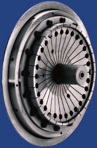
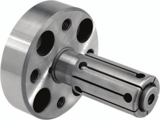
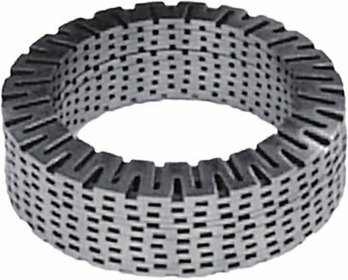
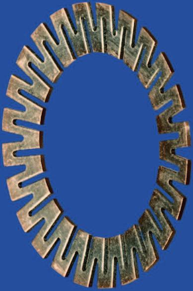
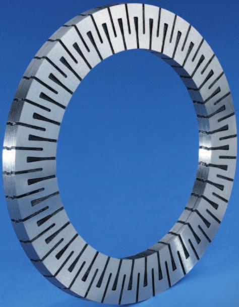
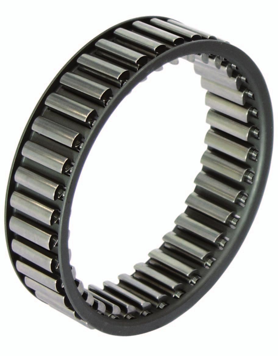
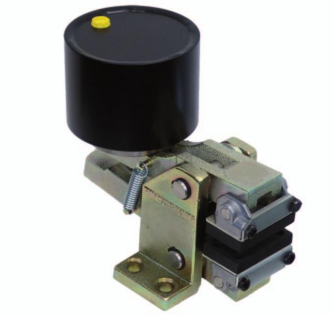
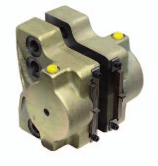
64 Freewheels Backstops Automatic protection against reverse running of conveyor belts, elevators, pumps and fans. Overrunning Clutches Automatic engaging and disengaging of drives. Indexing Freewheels For gradual feed of materials. Housing Freewheels Automatic engaging and disengaging of multi-motor drives for installations with continuous operation. Catalogue 84 Cage Freewheels For installation between customersupplied inner and outer rings. Catalogue 84 Catalogue 84 Catalogue 84 Industrial Disc Brakes Spring activated pneumatically, hydraulically or manually released. Industrial Disc Brakes Pneumatically activated spring released. Industrial Disc Brakes Spring activated electromagnetically released. Industrial Disc Brakes Hydraulically activated spring released. Catalogue 46 Catalogue 46 Catalogue 46 Catalogue 46 Two-part Shrink Discs External clamping connection. Advantages: Simple, secure mounting even without torque wrench. Three-part Shrink Discs External clamping connection for the fastening of hollow shafts on solid shafts. Cone Clamping Elements For Shaft-HubConnections. High torques with small dimensions. Star and Clamping Discs Ideal for Shaft-HubConnections for frequent release. Star Spring Washers Axial spring element for preloading of ball bearings. Catalogue 36 Catalogue 36 Catalogue 36 Catalogue 36 Catalogue 20 Force Limiters Reliable axial overload protection in piston rods. Catalogue 84 Brakes Clamping Units Spring activated hydraulically or pneumatically released. For secure and precise positioning of piston rods. Catalogue 46 Shaft-Hub-Connections Torque and Force Limiters Torque Limiters with Screw Face Reliable overload protection for tough operating conditions. Torque Limiters with Rollers With double or single Rollers. Through ratcheting or disengaging, also for 360 synchronous running. Torque Limiters with Balls Reliable overload protection with maximum response accuracy. Also backlash free. Catalogue 45 Catalogue 45 Catalogue 45 Torque Limiters with Friction Linings RIMOSTAT Torque Limiter for constant torque. Belleville Spring Torque Limiter for simple release. Catalogue 45 Flexible Couplings Large, allowed radial and angular misalignements. Minimum resiliency. Flexible Couplings Large, allowed radial and angular misalignements. Minimum resiliency. Flange-Couplings Rigid, easily removable shaft coupling with backlash free cone clamping elements. Rigid Couplings Rigid, easily removable shaft coupling with backlash free cone clamping elements. Catalogue 44 Catalogue 44 E Catalogue 36 Special Clamping Fixtures Custom made solutions for specific clamping problems. Collet Mandrels Universal, cost effective standard series. Fast collet change to other clamping diameters. Catalogue 49 Precision Clamping Fixtures Standard Parts for Clamping Fixtures The RINGSPANNSystem for the manufacture of your own precision clamping fixtures. Standard Clamping Fixtures Standard program in high precision, ready manufactured chucks and mandrels. Schaberweg Bad Homburg, Germany Telefon Telefax Clamping Clutches For the automatic coupling of rolls. Fast, safe and free from slipping connection. mailbox@ringspann.com 36e 10 Kronberger Offsetdruck 05/2011 Printed in Germany Couplings
NEW. Cone Clamping Elements Trantorque Keyless Locking Devices for very small diameters from 3 mm. E03.050e
 Cone Clamping Elements Trantorque Keyless Locking Devices for very small diameters from 3 mm NEW E03.050e Backlash free positioning Excellent concentricity Quick mounting by central clamping nut Issue
Shaft Couplings Flange-Couplings Rigid Shaft Couplings Flexible Couplings
 Shaft Couplings Flange-Couplings Rigid Shaft Couplings Flexible Couplings 44 Edition 2013/2014 RINGSPANN Registered Trademark of RINGSPANN GmbH, Bad Homburg 2 Table of Contents Flange-Couplings Page Flange-Couplings
SIT-LOCK self locking elements
 self locking elements Advantages of on the shaft-hub connection compared with traditional systems Easy assembly and disassembly Both actions take place by locking and unlocking the clamping screws with
For advanced drive technology CLAMPEX. Shaft-Hub-Connection. KTR Precision Joints CLAMPEX
 technology CLAMPEX Shaft-Hub-Connection CLAMPEX KTR Precision Joints 07 technology Table of contents Page Brief information 09 Selection and calculation -5 CLAMPEX -Selection Shaft diameter = d 0 10 0
For advanced drive technology CLAMPEX. Shaft-hub-connection. KTR Precision joints CLAMPEX
 technology CLAMPEX Shaft-hub-connection CLAMPEX KTR Precision joints 227 technology Table of contents Page Brief information 228 Selection and calculation 25-255 CLAMPEX -Selection Shaft diameter = d 0
Shaft Couplings Tru-Line Flange-Couplings Rigid Shaft Couplings Flexible Couplings
 Shaft Couplings Tru-Line Flange-Couplings Rigid Shaft Couplings Flexible Couplings Edition 2015/2016 RINGSPANN Registered Trademark of RINGSPANN GmbH, Bad Homburg Table of Contents Tru-Line Flange-Couplings
Shaft Couplings. Edition 2015/2016. Tru-Line Flange-Couplings Rigid Shaft Couplings Flexible Couplings
 Shaft Couplings Tru-Line Flange-Couplings Rigid Shaft Couplings Flexible Couplings Edition 2015/2016 RINGSPANN Registered Trademark of RINGSPANN GmbH, Bad Homburg 2 Table of Contents Tru-Line Flange-Couplings
FRICTIONAL CONNECTIONS CATALOGUE
 FRICTIONAL CONNECTIONS CATALOGUE Reprinting and all other forms of copying, not even partially, is prohibited without permission from Stüwe. Maschinenfabrik GmbH & Co. KG Production: Studio Salewski GmbH,
Flexible Couplings 44
 Flexible Couplings 44 RINGSPANN Registered Trademark of RINGSPANN GmbH, Bad Homburg MTY (81) 83 54 10 18 Why RINGSPANN Flexible Couplings? No connection of shafts without clutches It is a well-known fact
Locking Assemblies & Locking Elements
 US 01 2016 Locking Assemblies & Locking Elements Partner for Performance www.ringfeder.com Welcome to your system supplier for every aspect of power transmission Today s RINGFEDER POWER TRANSMISSION GMBH
CLAMPING ELEMENTS SELF-CENTRING RCK 15 TYPE SELF-CENTRING RCK 13 TYPE
 CLAMPING ELEMENTS The clamping system connects one or two component parts solidly to the drive shaft, which allow motion to be transmitted or to withstand an axial thrust. Friction connection enables gaps
Frictional Connections Catalogue
 MMADE IN GERMANY Frictional Connections Catalogue ADE IN GERMANY Certified in accordance with DIN ISO 9001:2008 FRICTIONAL CONNECTIONS TECHNOLOGY THAT CONNECTS Dear business partner, STÜWE GmbH & Co. KG
Locking Assemblies Shrink Discs Rigid Couplings.
 M I N I Locking Assemblies Shrink Discs Rigid Couplings www.mav.it our company We are an Italian company world renowned for our creativity and ethics. Established in 1989 we have rapidly built a reputation
Locking Assemblies & Locking Elements
 US 12 2010 Locking Assemblies & Locking Elements Partner for performance www.ringfeder.com A Global Presence For You The RINGFEDER POWER TRANSMISSION GMBH was founded in 1922 in Krefeld, Germany to fabricate
In-house development Own manufacturing Sole distributor in Germany Working with distributors worldwide
 In-house development Own manufacturing Sole distributor in Germany Working with distributors worldwide External Clamping devices Overview 3073 Mini-Range For very low torque transmission Very small profile
RFC SPECIALTY LOCKING DEVICES
 RINGFEDER Products are available from MARYLAND METRICS P.O. Box 261 Owings Mills, MD 21117 USA email: sales@mdmetric.com web: http://mdmetric.com phones: (410)358-3130 (800)638-1830 faxes: (410)358-3142
Force Limiters 49. RINGSPANN Registered Trademark of RINGSPANN GmbH, Bad Homburg
 Force Limiters 49 RINGSPANN Registered Trademark of RINGSPANN GmbH, Bad Homburg Why RINGSPANN Force Limiters? Why RINGSPANN Force Limiters? There are many ways of transmitting forces and torques in machines,
RCK CLAMPING ELEMENTS
 RCK CAMPING EEMENTS SERIES RCK 11 page 6 SERIES RCK 13 7 SERIES RCK 15 8 SERIES RCK 16 9 SERIES RCK 19 10 SERIES RCK 40 11 SERIES RCK 45 12 SERIES RCK 50 13 SERIES RCK 55 14 SERIES RCK 60 15 SERIES RCK
Solutions for power transmission. MAV-standardisarja.
 Solutions for power transmission MAV-standardisarja www.konaflex.fi L O C K I N G A S S E M B L I E S Shrink disc Mini Series Rigid Couplings www.mav.it our company We are an Italian company world renowned
RINGFEDER KEYLESS SHAFT/HUB CONNECTIONS LOCKING ASSEMBLIES TM LOCKING ELEMENTS TM SHRINK DISCS W-300-2
 RINGFEDER KEYLESS SHAFT/HUB CONNECTIONS LOCKING ASSEMBLIES TM LOCKING ELEMENTS TM SHRINK DISCS W-300-2 1 Ringfeder Corporation Catalog W-300-1 Shaft-Hub Locking Devices Ringfeder unique frictional, keyless
GatesFacts Technical Information Library Gates Compass Power Transmission CD-ROM version 1.2 The Gates Rubber Company Denver, Colorado USA
 MAKING THE RIGHT SHAFT CONNECTIONS Daniel Schwartz & Gary Porter Power Transmission Design August, 1996 Securing a belt pulley to a drive shaft often seems like such a routine task, that engineers and
Shaft Clamping Elements 8
 Clamping Elements 8 BACK NEXT The Company Cross & orse was established in 14 through the amalgamation of two long standing and well respected companies in the Power Transmission Industry, T.D. Cross and
Comparison Chart. extremely difficult. Finally, separated components can rarely be re-used.
 JAN 2014 Traditional Connections Why Go Keyless Keyed Bushing Systems Both QD and Taper-Lock bushing and weld-on hub systems are popular component mounting technologies. Yet both are ultimately keyed connections
RINGFEDER Locking Assemblies. Catalogue. RfN For high torques & axial loads
 RINGFEDER Locking Assemblies GB 03 04 Catalogue RfN 7014 For high torques & axial loads RINGFEDER Locking Assemblies RfN 7014 Please note that our guarantee refers to our products only. Because of the
TRADITIONAL SHAFT HUB CONNECTIONS
 TABLE OF CONTENTS MAV locking devices.... Pg. 2 Traditional shaft hub connections...pg. 3 Advantages of MAV locking devices...pg. 4 The wedge principle..... Pg. 5 Installation removal...pg. 6 Characteristics....
Shrink Discs, Smart-Lock & Shaft Couplings
 RINGFEDER Products are available from MARYLAND METRICS Shrink Discs, Smart-Lock & Shaft Couplings US 08 2009 Partner for performance RINGFEDER Products are available from MARYLAND METRICS P.O. Box 261
ROSTA Tensioning Motorbases Type MB. self-adjusting maintenance-free overload-proof non-slip dampen harmful vibrations extend belt drive
 Technology ROSTA Tensioning Type MB for Belt Drives The ROSTA elastic tensioning motorbase type MB, with the rubber suspension unit as swivel mounting, compensates continuously for all stretching, hopping,
Clamping elements and precision joints
 262 and precision joints CLAMPEX Types of clamping elements 264 Selection guide 266 Selection 267 Example of calculation/selection 268 Calculation of hubs and technical data 269 KTR 100 270 KTR 105 272
ROSTA MOTORBASES ROSTA. Self-Tensioning Motor Mount for Belt Drives. without slippage self-adjusting maintenance-free
 MOTORBASES Self-Tensioning Motor Mount for Belt Drives without slippage self-adjusting maintenance-free Technology Tensioning Motorbase Type MB for Belt Drives The elastic tensioning motorbase type MB,
Ball Rail Systems RE / The Drive & Control Company
 Ball Rail Systems RE 82 202/2002-12 The Drive & Control Company Rexroth Linear Motion Technology Ball Rail Systems Roller Rail Systems Standard Ball Rail Systems Super Ball Rail Systems Ball Rail Systems
Precision Modules PSK. The Drive & Control Company
 Precision Modules PSK The Drive & Control Company 2 Bosch Rexroth Coporation Precision Modules PSK R310A 2414 (2008.07) Linear Motion and Assembly Technologies Ball Rail Systems Roller Rail Systems Linear
RIGIFLEX -N RADEX -N. Steel laminae coupling. Steel laminae coupling. You will find continuously updated data in our online catalogue at
 117 Table of contents 117 Coupling selection steel laminae coupling 119 Description of coupling 121 General information 122 Types and applications 123 Technical data 124 Standard types 126 Special types
Intelligent Drivesystems NORD GRIPMAXX. Keyless Bushing System DRIVESYSTEMS F5210
 Intelligent Drivesystems NORD GRIPMAXX Keyless Bushing System F5210 The NORD GRIPMAXX Keyless Bushing System Concept Overview The NORD Gripmaxx Bushing System offers keyless interchangeable bushings for
Precision Modules PSK
 Precision Modules PSK The Drive & Control Company Rexroth Linear Motion Technology Ball Rail Systems Roller Rail Systems Standard Ball Rail Systems Super Ball Rail Systems Ball Rail Systems with Aluminum
CLAMPEX KTR 400 Operating/Assembly instructions
 1 of 10 The CLAMPEX clamping set is a frictionally engaged, detachable shaft-to-shaft connection for cylindrical shafts and bores without feather key. Table of contents 1 Technical data 2 2 Advice 2.1
Theory of Machines. CH-1: Fundamentals and type of Mechanisms
 CH-1: Fundamentals and type of Mechanisms 1. Define kinematic link and kinematic chain. 2. Enlist the types of constrained motion. Draw a label sketch of any one. 3. Define (1) Mechanism (2) Inversion
hydraulic actuated products EP: EP:
 In-house development Own manufacturing Sole distributor in Germany Working with distributors worldwide hydraulic actuated products EP: 0 812 397 EP: 1 666 748 Overview Hydraulic shrink disc SHS Standard
Selection Tool. on the Internet at in the section MÄDLER -Tools. Other sizes and designs on request. Connecting Shafts Page 766
 Couplings Overview Friction Clutches Friction Clutches Type B Axial Arrangement Friction Clutches Type C Transversal Flexibility Sliding Hubs with Torsionally-Flexible Coupling Multi-Disk Friction Clutches
ROSTA Tensioning Motorbases Type MB. self-adjusting maintenance-free overload-proof non-slip dampen harmful vibrations extend belt drive
 83 Technology ROSTA Tensioning Motorbase Type MB for Belt Drives The ROSTA elastic tensioning motorbase type MB, with the rubber suspension unit as swivel mounting, compensates continuously for all stretching,
LIGHTWEIGHT AND COMPACT. SERIES SL Nm. single-position multi-position. THE ultimate COUPLING from Nm
 LIGHTWEIGHT AND COMPACT L SAFETY COUPLINGS TOQLIGHT SEIES SL 5 700 Nm THE ultimate COUPLING from 5 700 Nm SEIES SL DESIGN / FEATUES Extremely lightweight construction Up to 60 % weight reduction in comparison
TORQLIGHT SAFETY COUPLINGS
 LIGHTWEIGHT AND COMPACT single-position TOQLIGHT SAFETY COUPLINGS SEIES SL 10 700 Nm THE ULTIMATE COUPLING FOM 10 700 Nm SEIES SL DESIGN / FEATUES Extremely lightweight construction Up to 60 % weight reduction
Assortment 2013_FPT BOOK.indb /02/13 6:57 PM
 Assortment Contents Why compete against your supplier when you can be our partner Chain Tensioners...14 see Chains section for details Anti-Vibration Mounts...224 Key Steel...225 Motor Rails...226 Self
MULTI CROSS RILLO. Highly flexible tyre coupling with taper bushings
 MULTI CROSS RILLO Highly flexible tyre coupling with taper bushings Maschinenfabrik Dipl.-Ing. Herwarth Reich GmbH Vierhausstr. 53 D-44807 Bochum P.O. Box 10 20 66 D-44720 Bochum Tel.: +49 / (0)234 / 959
In-house development Own manufacturing Sole distributor in Germany Working with distributors worldwide
 In-house development Own manufacturing Sole distributor in Germany Working with distributors worldwide External Clamping devices Overview 3173 Mini-Range For very low torque transmission Very small profile
Precision Modules PSK
 Precision Modules PSK 2 Bosch Rexroth AG Precision Modules PSK R999000500 (2015-12) Identification system for short product names Short product name Example:: P S K - 050 - N N - 1 System = Precision Module
Housing Freewheels for Multimotor Drives 80.1
 s for Multimotor Drives 80.1 RINGSPANN Registered Trademark of RINGSPANN GmbH, Bad Homburg s FKhG for Multimotor Drives for automatic connecting and disconnecting of drives on pumps, fans, generators etc.
EXAMPLES GEARS. page 1
 (EXAMPLES GEARS) EXAMPLES GEARS Example 1: Shilds p. 76 A 20 full depth spur pinion is to trans mit 1.25 kw at 850 rpm. The pinion has 18 teeth. Determine the Lewis bending stress if the module is 2 and
Guide units. For toolmaking, fixture manufacturing and machine engineering
 Guide units For toolmaking, fixture manufacturing and machine engineering Guide units in compliance with DIN, ISO and STEINEL standards or according to your specifications Guide pillars Guide and pillar
Accessories smart additions for efficiency and intelligent performance
 smart additions for efficiency and intelligent performance Metal bellows couplings Perfectionists you can count on Metal bellows couplings are designed for the highest requirements in servo drive technology.
TRANSMISSIONS. Mechanical Power Transmission
 TRANSMISSIONS Mechanical Power Transmission Dunlop BTL Ltd European Distribution Centre MPT House Brunswick Road Cobbs Wood Industrial Estate Ashford, Kent. UK TN23 1EL Contact us +44 (0)1233 663340 +44
FLEXIBLE COUPLINGS - RIGID COUPLINGS Up to Nm of torque and 205 mm bores
 Edition 10/2014 www.comintec.it FLEXIBLE COUPLINGS - RIGID COUPLINGS Up to 130.000 Nm of torque and 205 mm bores (BACKLASH FREE) Technology for Safety FLEXIBLE COUPLINGS - RIGID COUPLINGS (BACKLASH FREE):
Axial-radial cylindrical roller bearings
 Axial-radial cylindrical roller bearings Designs and variants.............. 320 Bearing data..................... 321 (Boundary dimensions, tolerances) Product table 5.1 Axial-radial cylindrical roller
OVERLOAD CLUTCHES FOR INDEX DRIVES
 The Driving Force in Automation OVERLOAD CLUTCHES FOR INDEX DRIVES WARNING WARNING This is a controlled document. It is your responsibility to deliver this information to the end user of the CAMCO indexer.
TOOLFLEX Operating-/Assembly Instructions
 D-807 Rheine heet: 5810 EN 1 of 19 Backlash-free, torsionally stiff and maintenance-free coupling is a backlash-free, torsionally stiff and maintenance-free metal bellow-type coupling designed to be used
Installation and Operational Instructions for ROBA -D Couplings Type 91_. _
 Please read the Installation and Operational Instructions carefully and follow them accordingly! Ignoring these Instructions may lead to malfunctions or to coupling failure, resulting in damage to other
Highest Performance: Dyna Series
 Highest Performance: Dyna Series GAM can. If you don t see exactly what you need, let us know. We can modify the Dyna Series gearboxes to meet your needs. Page provides a list of commonly requested modifications
Specifications. Trantorque GT CALL FAX
 GT Specifications The following pages contain engineering data and product specifications for GT. For CAD drawings of GT, please click on the part number to download the drawing. All drawings are in AutoCAD
Reducing Backlash / Increasing Rigidity Jaw Coupling Precision Jaw Oldham Helical Beam Disc coupling
 Precision Couplings A shaft coupling is a critical element in a robust and durable linear shaft drive. Misalignment of motor and drive shafts can cause loss of precision, noise and premature failure. By
SLEWING RING CHARACTERISTICS, APPLICATIONS
 SLEWING RING CHARACTERISTICS, APPLICATIONS Slewing rings are large-sized bearings which are able to accommodate combined load, i.e. axial, radial loads and tilting moment. They are usually provided with
CLAMP AND FLANGE COUPLINGS
 POWER TRANSMISSION RIGID COUPLINGS CLAMP AND FLANGE COUPLINGS 2 CLAMP AND FLANGE COUPLINGS RIGID COUPLINGS CLAMP AND FLANGE COUPLINGS FLANGE COUPLINGS DIN 116 Flange couplings are torsionally stiff, particularly
KISSsoft 03/2018 Tutorial 4
 KISSsoft 03/2018 Tutorial 4 Bolt calculation according to VDI 2230 KISSsoft AG T. +41 55 254 20 50 A Gleason Company F. +41 55 254 20 51 Rosengartenstr. 4, 8608 Bubikon info@kisssoft.ag Switzerland www.kisssoft.ag
Installation and Operating Instructions for EAS -NC clutch Type 45_. _. _ Sizes 02 and 03
 Table of contents: Please read and observe this Operating Instruction carefully! A possible malfunction or failure of the clutch and any damage may be caused by not observing it. Page 1: - Table of contents
Installation and Operating Instructions for RIMOSTAT -Friction Torque Limiter RSHD E e
 RIMOSTAT -Friction Torque Limiter e Schaberweg 30-38 Phone +49 6172 275-0 61348 Bad Homburg Fax +49 6172 275-275 Germany www.ringspann.com info@ringspann.com Issue: 02.11.2016 Version: 4 Drawn: RUPD Checked:
Z-LOCK INDEX Z2 Z5 Z5/Z6 ZSD ZSD Z-LOCK
 Z-LOCK INDEX TOPIC PAGE INTRODUCTION 1 TYPICAL APPLICATION 2 Z2 MEDIUM DUTY, NON SELF CENTERING 3-4 Z2 MINIMUM HUB DIAMETERS 5 Z2 FITTING INSTRUCTIONS 6 Z5 HEAVY DUTY, SELF CENTERING 7 Z5 MINIMUM HUB DIAMETERS
Features of the Ball Screw
 Features of the Driving Torque One Third of the Sliding Screw With the, balls roll between the screw shaft and the nut to achieve high effi ciency. Its required driving torque is only one third of the
RACK JACK. Synchronous Lifting Systems
 RACK JACK Synchronous Lifting Systems RACK JACK (ROUND RACK TYPE) Operation The Rack Jack from WMH Herion provides simple synchronous lifting motion. The system of rack and pinion transforms linear motion
BEVEL GEAR UNITS ZZ-SERVOLINE
 BEVEL GEAR UNITS ZZ-SERVOLINE ZZ-SERVOLINE GEARBOX DESIGN AND FUNCTIONAL FEATURES Gear Ratios i= 3:1 i= 4:1 i= 5:1 i= 6:1 i= 8:1 i= 10:1 i= 12:1 i= 15:1 Spiral Bevel Gear KLINGELNBERG tooth system Hypoid
GENERAL INFORMATION Locking is the rigid coupling of two or more elements which, in the absence of a coupling device, would otherwise be free to rotat
 123456789012345678901234567890121234567890123456 7 7 7 7 7 7 4567890123456789012123456789012345678901234567890121234567 7 1004 1004 34 7 134567890123456789012123456789012345678901234567890121234567 1234567890123456789012123456789012345678901234567890121234567
Backlash-free safety couplings. Backlash-free safety couplings. Product information. Optimal safety has a name: Guaranteed by two systems:
 ;;Engaged ;;Engaged Backlash-free safety couplings Product information Optimal safety has a name: Backlash-free safety couplings Guaranteed by two systems: ;;;; Locking Locking element - cylinder roller
Rexnord Tollok Locking Assemblies
 Tollok Catalog Download the most up-to-date version at www.rexnord.com/documentation Rexnord Tollok Locking Assemblies Why Choose Rexnord Tollok Locking Assemblies? Why Choose Rexnord? When it comes to
RE / STAR Tolerance Rings STAR Ball Knobs, Knob and Lever Type Handles
 RE 2 970/.99 STAR Tolerance Rings STAR Ball Knobs, Knob and Lever Type Handles STAR Tolerance Rings Product Overview Tolerance rings are made of hard, embossed spring steel strip and belong to the class
SKF FX Keyless Bushings
 SKF FX Keyless ushings Contents The SKF brand now stands for more than ever before, and means more to you as a valued customer. While SKF maintains its leadership as a high-quality bearing manufacturer
Shaft Mounted Speed Reducers
 s Metric Range Features The Challenge SMSR stands tall amongst the crowd. Packed full of attention to detail, the Challenge SMSR delivers performance in the harshest of applications. Shaft mounted drives
Standard with cone bushing. Backlash-free Safety Clutch
 EAS -Compact ratchetting clutch/synchronous clutch The Backlash-free Safety Clutch for Standard with cone bushing Packaging Machinery Machine Tools Paper Machinery Indexing Drives Servo Motors EAS -NC
U.S. Tsubaki AS Series
 U.S. TSUBAKI POWER-LOCK U.S. Tsubaki AS Series ENTER THE YLESS SOCIETY Our POWER-LOCK solves your problems. Eliminate backlash damage to keyways from heavy loads the U.S. Tsubaki POWER-LOCK fits tightly
Power-Lock shaft-hub locking devices provide simple and highly secure connections.
 POWER-LOCK Power-Lock shaft-hub locking devices provide simple and highly secure connections. AS Series Multipurpose locking devices available in stainless steel and electroless nickelplated finish, in
Electromagnetic clutch-brake combinations INTORQ
 Electromagnetic clutch-brake combinations INTORQ 14.800 14.867 7.5 120 Nm setting the standard 2 CBC en 5/2005 Contents Clutch-brake combinations Product information 4 Type code 6 Design selection 8 Overview
Installation and Operational Instructions for EAS - HTL housed overload clutch Sizes 01 3 Type 490._24.0
 Please read these Operational Instructions carefully and follow them accordingly! Ignoring these Instructions may lead to malfunctions or to clutch failure, resulting in damage to other parts. Contents:
Power Transmission. Installation and Operating Instructions for Integrated Freewheels FXRV and FXRT. E e.
 Power Transmission Installation and Operating Instructions for Schaberweg 30-34 Telephone +49 6172 275-0 61348 Bad Homburg Telefax +49 6172 275-275 Germany www.ringspann.com mailbox@ringspann.com Issue:
Please read these Operational Instructions carefully and follow them accordingly!
 Sizes 3 to 5 Please read these Operational Instructions carefully and follow them accordingly! Ignoring these Instructions may lead to malfunctions or to coupling failure, resulting in damage to other
Installation and Operational Instructions for EAS -Compact overload clutch, Type 49_. 4._ Sizes 4 and 5
 Please read these Operational Instructions carefully and follow them accordingly! Ignoring these Instructions may lead to malfunctions or to clutch failure, resulting in damage to other parts. Contents:
Shaft Mounted Speed Reducer. Technical Catalogue
 Shaft Mounted Speed Reducer Technical Catalogue Where others fit, We perform Contents The Challenge SMSR stands tall amongst the crowd. Packed full of attention to detail, the Challenge SMSR delivers performance
 heet: 1 of 22 Backlash-free, torsionally stiff and maintenance-free coupling Type with setscrew Type with clamping hubs Type KN (Taper hubs) Type M with setscrew Type M with clamping hubs Type PI 11-3379-883
Standard model for offset drives by chainwheel, sprocket or gear. Chain coupling adaptor for in-line drives, simple & compact
 Type DSF/EX friction torque limiters Friction torque limiters are simple low cost devices that remove shock loads and protect machinery from overload damage. Easy torque setting and wide torque range Bi-directional
EXAMPLES INTRODUCTION
 AMEM 316 (AUTO308): Machine Elements I EXAMPLES INTRODUCTION EXAMPLES INTRODUCTION Example 1 (Hamrock p.53) As shown in figure 2.12(a), a 3m long bar is supported at the left end (B) by a 6 ram diameter
EJP SERIES Right-angle Worm
 EJP SERIES T he EJP series is ideal for demanding applications requiring high efficiency, torsional rigidity and zero backlash. It s lightweight, black anodized aluminum housing and dual input/output seals
Addendum to the Assembly and Operating Instructions
 Drive Technology \ Drive Automation \ System Integration \ Services *22866868_0416* Addendum to the Assembly and Operating Instructions SEW-EURODRIVE GmbH & Co KG P.O. Box 3023 76642 Bruchsal/Germany Phone
KTR Torque Limiters Overload Protection Systems
 KT Torque Limiters Overload Protection Systems UFLEX - Friction Disk - Zero Backlash Ball Detent KT SI - Ball/oller Bearing Style KT SI Compact - Zero Backlash Ball Detent Catalog Contents (Metric) Page
Highest Precision: Dyna Series
 Highest Precision: Dyna Series GAM can. Just ask! If you don t see exactly what you need, let us know. We can modify the Dyna Series gearboxes to meet your needs. Page 3 provides a list of commonly requested
3. BEARING ARRANGEMENT DESIGN
 3. BEARING ARRANGEMENT DESIGN 3.1 GENERAL PRINCIPLES OF ROLLING BEARING ARRANGEMENT DESIGN Rotating shaft or another component arranged in rolling bearings is guided by them in radial as well as in axial
Dr. TRETTER AG. Tolerance Rings. safe cost-effective fast assembly
 Dr. TRETTER AG Tolerance Rings safe cost-effective fast assembly Tolerance Rings are corrugated metal strips manufactured of high quality spring steel. Tolerance Rings are a fastening device between two
Self-Adjusting Clutch (SAC) Technology Special tools / User instructions
 Technology Special tools / User instructions") Self-Adjusting Clutch (SAC) Technology Special tools / User instructions The content of this brochure shall not be legally binding and is for information purposes only. To the extent legally permissible,
Self-Adjusting Clutch (SAC) Technology Special tools / User instructions The content of this brochure shall not be legally binding and is for information purposes only. To the extent legally permissible,
CONTENT. 1. Syllabus 2. Introduction 3. Shaft 4. Coupling. Rigid coupling. Flange coupling. Sleeve (or) muff coupling Split muff coupling
 muff coupling Split muff coupling") UNIT II 1. Syllabus 2. Introduction 3. Shaft 4. Coupling Rigid coupling CONTENT Flange coupling Protected flange coupling Unprotected flange coupling Marine type flange coupling Sleeve (or) muff coupling
UNIT II 1. Syllabus 2. Introduction 3. Shaft 4. Coupling Rigid coupling CONTENT Flange coupling Protected flange coupling Unprotected flange coupling Marine type flange coupling Sleeve (or) muff coupling
bearings (metric series)
") Taper roller bearings (metric series) 32302 B J2 / Q CL7C Nomenclature 1 2 3 4 1. Contact angle: 3. Features: B Larger contact angle than standard Q Improved friction torque characteristics and raceway
Taper roller bearings (metric series) 32302 B J2 / Q CL7C Nomenclature 1 2 3 4 1. Contact angle: 3. Features: B Larger contact angle than standard Q Improved friction torque characteristics and raceway
C-SERIES S-SERIES. Metric Machine Screw Jacks EMA LINEAR ACTUATORS
 C-SERIES S-SERIES Metric Machine Screw Jacks EMA LINEAR ACTUATORS Power Jacks has a proud engineering heritage dating from the earliest years of the 20th Century. A heritage that is about excellence: about
The right torque in the right place
 Technical article for the trade press (Parts I, II and III) October 2017 Power transmission / conveying engineering / design engineering / machine elements / system and work safety The right torque in
Locking elements. Technical information
 Technical information ocking elements.principle of operation. These parts operate on the basis of an interference fit between two conical rings crewed together. The outer ring expands and exerts a pressure
Slotted nut NMG. Housing nut GWR. Bosch Rexroth AG. for economical constructions. a min. 0,3. M A = tightening torque of slotted nut.
 R310EN 3301 (2009.08) Precision Ball Screw Assemblies Bosch Rexroth AG 113 Slotted nut NMG for economical constructions B D d d1 b M A = tightening torque of slotted nut a min. 0,3 Polyamide insert Designation
Installation and Operational Instructions for ROBA -DS couplings Type 95. _ (disk pack HT) Sizes
 Sizes") (B.9.7..ATEX.EN) Please read these Operational Instructions carefully and follow them accordingly! Ignoring these Instructions may lead to malfunctions or to coupling failure, resulting in damage to other
(B.9.7..ATEX.EN) Please read these Operational Instructions carefully and follow them accordingly! Ignoring these Instructions may lead to malfunctions or to coupling failure, resulting in damage to other
Installation and Operational Instructions for EAS -Compact overload clutch Type 49_. 4._ Sizes 01 to 3
 Please read these Operational Instructions carefully and follow them accordingly! Ignoring these Instructions may lead to malfunctions or to clutch failure, resulting in damage to other parts. Contents