PARALLEL INDEX DRIVES TP Series
|
|
|
- Katrina Hunter
- 5 years ago
- Views:
Transcription


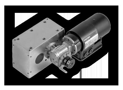

1 PARALLEL INDEX DRIVES TP Series

2 Calculations J = moment of inertia Application examples Direct driven belt/chain = M B + M B M B = c a n 2π n x t² M R = µ g R m = M B + M R + (M ST )* M ST = m g R M AN = ((M B c m ) + (M ST C V )) 360 n a Indirect driven belt/chain = M B + M R i² i P = M AN f a 9550 n *with one-sided lifting of loads J = moment of inertia [kgm²] M B = acceleration torque [Nm] M R = friction torque [Nm] = indexer torque [Nm] M ST = static torque [Nm] M AN = drive torque [Nm] µ = friction coefficient g = acceleration of gravity = 9,81m/s² R = radius m = mass [kg] a = switching angle [ ] t s = index time [s] n = number of stops i = ratio P = drive power [kw] n = efficiency worm gear f a = drive speed [1/min] Arm = M B + M ST Transducer of rotations in horizontal movement = M B + M R MS = ACCELERATION MSO MS30 M250 c a = acceleration coefficient c m = performance coefficient c v = speed coefficient Sorting and Isolation = M B + M ST a becomes a b will be removed Rotate part = M B a b a a b a b a a a a 82
 to suit your needs. The drive shaft as well as the output shaft are available as double sided shafts with and without keyways.")
3 Ø14h B A Ø14h M5x8/12 (16x) Ø95 TP040 Dimensions The measurements shown here illustrate the standard unit. We will gladly customize the housing and or shaft(s) to suit your needs. The drive shaft as well as the output shaft are available as double sided shafts with and without keyways. If you would like to add additional holes into the housing yourself, please contact us for possible drilling depths. The dimensions for the gearmotor may change based on the gearmotor size and options required for the application. 83 A = Drive Shaft B = Output Shaft
4 TP040 Load Table Angle on Output Shaft [ ] Number of Stops n Index Angle [ ] Acceleration Form MS Indexer Torque [Nm] Moment of Inertia J [kgm²] Mechanical Index Time t S [S] MS MS MS MS MS MS MS MS MS MS MS MS MS MS MS MS MS ¹ 270 MS MS MS MS ¹ 270 MS MS MS MS ¹ 270 MS MS MS MS ¹) Parallel drives with stop numbers 6, 8 and 10 are designed as a double index, i.e. with each full rotation of the drive shaft, two indexes occur in the output. ²) Parallel drives with 12 stops are designed as a four step index, i.e. with each full rotation of the drive shaft, four indexes occur in the output. ³) The additional load occurring with chains and belts due to friction is not taken into consideration here and must be calculated separately. Main Dimensions Shaft distance [mm] 40 Weight without drive [kg] 2 Switching angle [ ] see Load Table (other switching angles upon request) Number of stops 1,2,3,4,5,6,8,10 (other numbers of stops upon request) Rotating direction right, left, oscillating Mounting position ANY Capacities Max. Output torque See Load Table Input Shaft Load rating dynamic [kn] 4.36 Load rating static [kn] 2.24 Output Shaft Load rating dynamic [kn] 4.36 Load rating static [kn]
s to suit your needs.")
5 Ø19h B A Ø19h M8x14/18 (16x) B Ø110 TP063 Dimensions The measurements shown here illustrate the standard unit. We will gladly customize the housing and or shaft(s)s to suit your needs. The drive shaft as well as the output shaft are available as double sided shafts with and without keyways. If you would like to add additional holes into the housing yourself, please contact us for possible drilling depths. The dimensions for the gearmotor may change based on the gearmotor size and options required for the application. 85 A = Drive Shaft B = Output Shaft
6 TP063 Load Table Angle on Output Shaft [ ] Number of Stops n Index Angle [ ] Acceleration Form MS Indexer Torque [Nm] Moment of Inertia J [kgm²] Mechanical Index Time t S [S] MS MS MS MS MS MS MS MS MS MS MS MS MS MS MS MS MS ¹ 270 MS MS MS MS ¹ 270 MS MS MS MS ¹ 270 MS MS MS MS ² 240 MS ¹) Parallel drives with stop numbers 6, 8 and 10 are designed as a double index, i.e. with each full rotation of the drive shaft, two indexes occur in the output. ²) Parallel drives with 12 stops are designed as a four step index, i.e. with each full rotation of the drive shaft, four indexes occur in the output. ³) The additional load occurring with chains and belts due to friction is not taken into consideration here and must be calculated separately. Main Dimensions Shaft distance [mm] 63 Weight without drive [kg] 8 Switching angle [ ] see Load Table (other switching angles upon request) Number of stops 1,2,3,4,5,6,8,10,12 (other numbers of stops upon request) Rotating direction right, left, oscillating Mounting position ANY Capacities Max. Output torque See Load Table Input Shaft Load rating dynamic [kn] 11.9 Load rating static [kn] 6.55 Output Shaft Load rating dynamic [kn] 8.06 Load rating static [kn]
 to suit your needs. The drive shaft as well as the output shaft are available as double sided shafts with and without keyways.")
7 Ø25h B A Ø25h6 100 M8x15/19 (16x) B Ø127 TP080 Dimensions The measurements shown here illustrate the standard unit. We will gladly customize the housing and or shaft(s) to suit your needs. The drive shaft as well as the output shaft are available as double sided shafts with and without keyways. If you would like to add additional holes into the housing yourself, please contact us for possible drilling depths. The dimensions for the gearmotor may change based on the gearmotor size and options required for the application. 87 A = Drive Shaft B = Output Shaft
8 TP080 Load Table Angle on Output Shaft [ ] Number of Stops n Index Angle [ ] Acceleration Form MS Indexer Torque [Nm] Moment of Inertia J [kgm²] Mechanical Index Time t S [S] MS MS MS MS MS MS MS MS MS MS MS MS MS MS MS MS MS ¹ 270 MS MS MS MS ¹ 270 MS MS MS MS ¹ 270 MS MS MS MS ² 240 MS ¹) Parallel drives with stop numbers 6, 8 and 10 are designed as a double index, i.e. with each full rotation of the drive shaft, two indexes occur in the output. ²) Parallel drives with 12 stops are designed as a four step index, i.e. with each full rotation of the drive shaft, four indexes occur in the output. ³) The additional load occurring with chains and belts due to friction is not taken into consideration here and must be calculated separately. Main Dimensions Shaft distance [mm] 80 Weight without drive [kg] 16 Switching angle [ ] see Load Table (other switching angles upon request) Number of stops 1,2,3,4,5,6,8,10,12 (other numbers of stops upon request) Rotating direction right, left, oscillating Mounting position ANY Capacities Max. Output torque See Load Table Input Shaft Load rating dynamic [kn] 13.8 Load rating static [kn] 8.3 Output Shaft Load rating dynamic [kn] 13.8 Load rating static [kn]
 to suit your needs. The drive shaft as well as the output shaft are available as double sided shafts with and without keyways.")
9 Ø30k Ø30k M10x16/ Ø147 TP100 Dimensions The measurements shown here illustrate the standard unit. We will gladly customize the housing and or shaft(s) to suit your needs. The drive shaft as well as the output shaft are available as double sided shafts with and without keyways. If you would like to add additional holes into the housing yourself, please contact us for possible drilling depths. The dimensions for the gearmotor may change based on the gearmotor size and options required for the application. 89 A = Drive Shaft B = Output Shaft
10 TP100 Load Table Angle on Output Shaft [ ] Number of Stops n Index Angle [ ] Acceleration Form MS Indexer Torque [Nm] Moment of Inertia J [kgm²] Mechanical Index Time t S [S] MS MS MS MS MS MS MS MS MS MS MS MS MS MS MS MS MS ¹ 270 MS MS MS MS ¹ 270 MS MS MS MS ¹ 270 MS MS MS MS ² 240 MS ¹) Parallel drives with stop numbers 6, 8 and 10 are designed as a double index, i.e. with each full rotation of the drive shaft, two indexes occur in the output. ²) Parallel drives with 12 stops are designed as a four step index, i.e. with each full rotation of the drive shaft, four indexes occur in the output. ³) The additional load occurring with chains and belts due to friction is not taken into consideration here and must be calculated separately. Main Dimensions Shaft distance [mm] 100 Weight without drive [kg] 25 Switching angle [ ] see Load Table (other switching angles upon request) Number of stops 1,2,3,4,5,6,8,10,12 (other numbers of stops upon request) Rotating direction right, left, oscillating Mounting position ANY Capacities Max. Output torque See Load Table Input Shaft Load rating dynamic [kn] 40 Load rating static [kn] 28 Output Shaft Load rating dynamic [kn] 40 Load rating static [kn] 28 90
 145 85 53 100 61 69 137 135 137 103 135 364 94 176 TP125 Dimensions The measurements shown here illustrate the standard unit.")
11 Ø38k Ø38k6 150 M12x25/30 (16x) TP125 Dimensions The measurements shown here illustrate the standard unit. We will gladly customize the housing and or shaft(s) to suit your needs. The drive shaft as well as the output shaft are available as double sided shafts with and without keyways. If you would like to add additional holes into the housing yourself, please contact us for possible drilling depths. The dimensions for the gearmotor may change based on the gearmotor size and options required for the application. 91 A = Drive Shaft B = Output Shaft
12 TP125 Load Table Angle on Output Shaft [ ] Number of Stops n Index Angle [ ] Acceleration Form MS Indexer Torque [Nm] Moment of Inertia J [kgm²] Mechanical Index Time t S [S] MS MS MS MS MS MS MS MS MS MS MS MS MS MS MS MS MS ¹ 270 MS MS MS MS ¹ 270 MS MS MS MS ¹ 270 MS MS MS MS ² 240 MS ¹) Parallel drives with stop numbers 6, 8 and 10 are designed as a double index, i.e. with each full rotation of the drive shaft, two indexes occur in the output. ²) Parallel drives with 12 stops are designed as a four step index, i.e. with each full rotation of the drive shaft, four indexes occur in the output. ³) The additional load occurring with chains and belts due to friction is not taken into consideration here and must be calculated separately. Main Dimensions Shaft distance [mm] 125 Weight without drive [kg] 12 Switching angle [ ] see Load Table (other switching angles upon request) Number of stops 1,2,3,4,5,6,8,10,12 (other numbers of stops upon request) Rotating direction right, left, oscillating Mounting position ANY Capacities Max. Output torque See Load Table Input Shaft Load rating dynamic [kn] 51 Load rating static [kn] 39 Output Shaft Load rating dynamic [kn] 51 Load rating static [kn] 39 92
13 Ø48k Ø48k6 186 M12x19/24 (16x) Ø197 TP160 Dimensions The measurements shown here illustrate the standard unit. We will gladly customize the housing and or shaft(s) to suit your needs. The drive shaft as well as the output shaft are available as double sided shafts with and without keyways. If you would like to add additional holes into the housing yourself, please contact us for possible drilling depths. The dimensions for the gearmotor may change based on the gearmotor size and options required for the application. 93 A = Drive Shaft B = Output Shaft
14 TP160 Load Table Angle on Output Shaft [ ] Number of Stops n Index Angle [ ] Acceleration Form MS Indexer Torque [Nm] Moment of Inertia J [kgm²] Mechanical Index Time t S [S] MS MS MS MS MS MS MS MS MS MS MS MS MS MS MS MS MS ¹ 270 MS MS MS MS ¹ 270 MS MS MS MS ¹ 270 MS MS MS MS ² 240 MS ¹) Parallel drives with stop numbers 6, 8 and 10 are designed as a double index, i.e. with each full rotation of the drive shaft, two indexes occur in the output. ²) Parallel drives with 12 stops are designed as a four step index, i.e. with each full rotation of the drive shaft, four indexes occur in the output. ³) The additional load occurring with chains and belts due to friction is not taken into consideration here and must be calculated separately. Main Dimensions Shaft distance [mm] 160 Weight without drive [kg] 117 Switching angle [ ] see Load Table (other switching angles upon request) Number of stops 1,2,3,4,5,6,8,10,12 (other numbers of stops upon request) Rotating direction right, left, oscillating Mounting position ANY Capacities Max. Output torque See Load Table Input Shaft Load rating dynamic [kn] 51 Load rating static [kn] 39 Output Shaft Load rating dynamic [kn] 168 Load rating static [kn]
RIGHT ANGLE DRIVES TG Series
 RIGHT ANGLE DRIVES TG Series Right Angle Fixed Index Drives TG Series The rotary index table transforms a constant input drive motion into an intermittent output drive motion. The intermittent drive motion
ROTARY INDEX TABLES RT Series
 ROTARY INDEX TABLES RT Series RT100 For mounted accessories up to Ø 800mm. For rapid assembly of small parts, inspection or feeding parts. 14 Fixed Index Drives The rotary index table transforms a constant
Vertical Linear Drive with Toothed Belt and Integrated Recirculating Ball Bearing Guide Series OSP-E..BV
 Vertical Linear Drive with Toothed Belt and Integrated Recirculating Ball Bearing Guide Series OSP-E..BV Contents Description Page Overview 25-28 Technical Data 29-33 Dimensions 34 Order Instructions 35
New Product. High speed transfer 0.5 sec./cycle realized. Linear type P&P unit. PPLX Series PPLX SERIES CC-N-371A 4
 High speed transfer 0.5 sec./cycle realized New Product Linear type P&P unit PPLX Series PPLX SERIES CC-N-371A 4 Lb stroke length (vertical) Reliable and high speed transfer 0.5 second/cycle Available
Vertical Linear Drive with Toothed Belt and Integrated Recirculating Ball Bearing Guide Series OSP-E..BV
 Vertical Linear Drive with and Integrated Recirculating Ball Bearing Guide Series OSP-E..BV Overview...25-28 Technical Data...29-31 Dimensions...32-33 25 Features TOOTHED BELT DRIVE FOR VERTICAL MOVEMENTS
Vertical Linear Drive with Toothed Belt and Integrated Recirculating Ball Bearing Guide Series OSP-E..BV
 Vertical Linear Drive with and Integrated Recirculating Ball Bearing Guide Series OSP-E..BV Contents Description Page Overview 25-28 Technical Data 29-31 Dimensions 32-33 25 Parker Hannifin Corporation
COMPACT UNIVERSAL SLIDES
 COMPACT UNIVERSAL SLIDES English edition 168 COMPACT UNIVERSAL SLIDES KUS CONTENTS PRODUCT DESCRIPTION 170 172 COMPACT UNIVERSAL SLIDES 173 CALCULATION PRINCIPLES/ ASSEMBLY INSTRUCTIONS 17 176 Lx Mz Kx
ROTARY TABLES SERIE TC TECHNOLOGY THAT INSPIRES
 ROTARY TABLES SERIE TC TECHNOLOGY THAT INSPIRES TC FIXED-STATION ROTARY INDEXING TABLES TC ROTARY INDEXING TABLE TC ROTARY INDEXING TABLE: RELIABILITY FOR A LIFETIME EXTENDED WARRANTY Using our rotary
Inkoturn couplings. INKOMA - GROUP Couplings. Product description. Inkoturn couplings IKT. FRANCIS AND FRANCIS Ltd.
 Product description The INKOM Inkoturn coupling (IKT) is a flexible coupling with high torsional rigidity, which has been developed for applications requiring high speed and where shaft is present. INKOM
Roller gear index table
 Roller gear index table model MDF www.pascaleng.co.jp Roller gear index table model MDF Roller gear index table model MDF Support table model MDS 2 Maintenance-free and high speed indexing Rolling transmission
Linear Drive with Ball Screw Drive Series OSP-E..SB
 Linear Drive with Ball Screw Drive Series OSP-E..SB Contents Description Data Sheet No. Page Overview 1.30.001E 47-50 Technical Data 1.30.002E-1 to 5 51-55 Dimensions 1.30.002E-6, -7 56-57 Order instructions
Description Symbol Definition or explanation Rated torque T KN Torque that can continuously be transmitted over the entire permissible speed range
 Coupling selection Normally the is selected according to the nominal torque ( ) shown in the list of technical data, like all other coupling systems. In all cases the torque ( ) must exceed the maximum
APPLICATION NOTE AN-ODP March 2009
 Application Note Title AN-ODP-37 Braking Resistor Selection and Usage Revision History Version Comments Author Date 2.21 Previous version NX 15/6/07 3.00 Revised to new format, additional information added
Series CRB2. Rotary Actuator Vane Style. Size: 10, 15, 20, 30, 40 CRB2 CRBU2 CRB1 MSU CRJ CRA1 CRQ2 MSQ MRQ D- 20- Series Variations.
 Rotary Actuator Vane Style Series :,,,, 4 1 Series Variations Standard Vane type Port location Rotating angle Shaft type Fluid (S) ouble vane () Side ported (Nil) Axial ported (E) 9 18 27 ouble shaft W
EXAMPLES GEARS. page 1
 (EXAMPLES GEARS) EXAMPLES GEARS Example 1: Shilds p. 76 A 20 full depth spur pinion is to trans mit 1.25 kw at 850 rpm. The pinion has 18 teeth. Determine the Lewis bending stress if the module is 2 and
L1 (Standard Motor Length) L2 (Brake Motor Length)
 L2 (Brake Motor Length)") HepcoMotion Geared Motor Option The optional geared motor will be the preferred choice for many applications as it provides an excellent combination of power, accuracy, flexibility and value. HepcoMotion
HepcoMotion Geared Motor Option The optional geared motor will be the preferred choice for many applications as it provides an excellent combination of power, accuracy, flexibility and value. HepcoMotion
3.2 lean SL 5 Technical data & dimension sheets lean SL series Technical data
 3.2.1 lean SL series Technical data 3.2 lean SL 5 Technical data & dimension sheets 3.2.1 lean SL series Technical data lean SL lean SL double! Make sure that the article number refers to the correct pinion
PNCE ELECTRIC CYLINDERS
 ELECTRIC CYLINDERS Every care has been taken to ensure the accuracy of the information contained in this catalogue, but no liability can be accepted for any errors or omissions. We reserve the right to
DRIVE-TECHNOLOGY INKOMA - GROUP. Inkoturn couplings
 INKOM-GROUPINKOM - DRIVE-TECHNOLOGY GROUP Inkoturn couplings INKOM-GROUP Headoffice Sitz der INKOM Maschinenbau GmbH Neue Reihe 44 D - 3862 Schandelah - Germany phone: +49/(0)5306-922-0 fax: +49/(0)5306-922-50
Rotary Index Tables Typ RT
 Rotary Index Tables Typ RT Going full-pitch for a good turn Passion for Automation this motto sums up our company philosophy and our overall approach toward business. Our broad product range forms the
COMBIBOX. Program Schedule. Design. COMBIBOX clutch-brake-combination type 10 / 09 / 06. Attachments
 clutch-brake-combination 10 / 09 / 06 with an energised to engage single sided clutch / brake... 10 with an energised to engage single sided clutch without brake... 09 with an energised to engage single
PNCE ELECTRIC CYLINDER
 ELECTRIC CYLINDER INDEX Characteristics 1 Structural design 2 How to order 3 Technical data 4 Dimensions 11 Accessories 12 Lubrication position 2 Motor adapter with coupling 2 Motor side drive with timing
mechanics LES functional overview LES 4 LES 6 LES 5
 LES functional overview LES 4 with spindle drive Overview 2-54 2-56 LES 6 2-58 with spindle drive LES 5 2-60 with spindle drive Calculations 2-62 Combination examples Motor modules Clutch housing Motor
G10TE HG Linear Guideway
 G10TE01-0310 I HG Linear Guideway Preface... 1 1... 1 1-1... 1 1-2... 2 1-3... 3 1-3-1 1-3-2 1-4... 4 1-4-1 1-4-2 1-4-3 1-4-4 1-4-5 1-5... 6 1-5-1 1-5-2 1-5-3 1-5-4 1-6... 9 1-7... 9 1-7-1 1-7-2 1-8...
WIESEL SPEEDLine WHZ80 with roller guideway and AT toothed belt
 WIESEL WHZ80 with roller guideway and AT toothed belt All figures shown in millimeters. Note: Mounted wipers on request. The use of a long power bridge increases the total length. Technical data Linear
III B.Tech I Semester Supplementary Examinations, May/June
 Set No. 1 III B.Tech I Semester Supplementary Examinations, May/June - 2015 1 a) Derive the expression for Gyroscopic Couple? b) A disc with radius of gyration of 60mm and a mass of 4kg is mounted centrally
BIMEE-007 B.Tech. MECHANICAL ENGINEERING (BTMEVI) Term-End Examination December, 2013
 Term-End Examination December, 2013") No. of Printed Pages : 5 BIMEE-007 B.Tech. MECHANICAL ENGINEERING (BTMEVI) Term-End Examination December, 2013 0 0 9 0 9 BIMEE-007 : ADVANCED DYNAMICS OF MACHINE Time : 3 hours Maximum Marks : 70 Note
No. of Printed Pages : 5 BIMEE-007 B.Tech. MECHANICAL ENGINEERING (BTMEVI) Term-End Examination December, 2013 0 0 9 0 9 BIMEE-007 : ADVANCED DYNAMICS OF MACHINE Time : 3 hours Maximum Marks : 70 Note
Electromagnetic clutch-brake combinations INTORQ
 Electromagnetic clutch-brake combinations INTORQ 14.800 14.867 7.5 120 Nm setting the standard 2 CBC en 5/2005 Contents Clutch-brake combinations Product information 4 Type code 6 Design selection 8 Overview
Metal bellows couplings
 Metal bellows couplings Product information / Design Typical characteristics of metal bellows couplings Backlash-free transmission of torque High torsional stiffness, precision of transmission of rotational
The University of Melbourne Engineering Mechanics
 The University of Melbourne 436-291 Engineering Mechanics Tutorial Twelve General Plane Motion, Work and Energy Part A (Introductory) 1. (Problem 6/78 from Meriam and Kraige - Dynamics) Above the earth
SHS. Caged Ball LM Guide Global Standard Size Model SHS. Point of Selection. Point of Design. Options. Model No. Precautions on Use
 Caged Ball LM Guide Global Standard Size Model LM block LM rail Endplate End seal 45 Ball Ball cage Cross section 45 * For the Ball Cage, see. Point of Selection Point of Design Options Model No. Precautions
Flexible Couplings BIPEX Series
 Siemens AG 2008 Flexible Couplings BIPEX Series /2 Overview /2 Benefits /2 Application /3 Design /4 Technical data /5 Type BWN /5 Selection and ordering data /6 Type BWT /6 Selection and ordering data
Rotational Kinematics and Dynamics Review
 Rotational Kinematics and Dynamics Review 1. The Earth takes slightly less than one day to complete one rotation about the axis passing through its poles. The actual time is 8.616 10 4 s. Given this information,
Linear Actuator with Ball Screw Series OSP-E..S. Contents Description Overview Technical Data Dimensions 89
 Linear Actuator with Ball Screw Series OSP-E..S Contents Description Page Overview 79-82 Technical Data 83-88 Dimensions 89 79 The System Concept ELECTRIC LINEAR ACTUATOR FOR HIGH ACCURACY APPLICATIONS
Technical Data and Dimensions EMC
 Technical Data Electromechanical Cylinders EMC 5 Technical Data and Dimensions EMC Sizes 3 to 00 follow the standard cylinder series according to ISO 555. Built-in ball screw drives have a diameter of
STH SERIES Hollow Rotary Index Tables
 STH SERIES T he STH is an excellent fit for mid-range index table applications that require high accuracy, flexible mounting and a large hollow shaft. This product sets the standard for rotary positioning
The STH is a mid-range speed and torque gear reducer that
 -SERIES The is a mid-range speed and torque gear reducer that sets a new standard for rotary positioning performance at an exceptional price point. A SHIMPO ABLE planetary gearbox is the interface between
PRECISION MOTION CONTROL
 PRECISION MOTION CONTROL Application & Selection Guide RPS System 5 Racks 9 ROLLER PINION TECHNOLOGY Gears 15 Pinions & Accessories 21 Precision Ring Drive System 31 RPS System Life 43 Harmonic Gearhead
COMBIBOX Program Schedule. Design. COMBIBOX Clutch-brake-combination type 10 / 09 / 06. Attachments input
 COMBIBOX Program Schedule COMBIBOX Clutch-brake-combination type 10 / 09 / 06 with an energised to engage single sided clutch / brake COMBIBOX 10 page 37 with an energised to engage single sided clutch
Highly Flexible Couplings ELPEX-B Series
 Siemens AG 2015 Highly Flexible Couplings ELPEX-B Series /2 Overview /2 Benefits /2 Application /2 Design / Technical data /5 Type EBWN /5 Selection and ordering data /6 Type EBWT /6 Selection and ordering
Sizes 50, 65, 80. Presence of internal channels for re-lubrication Large range of axis mounting accessories
 > Series 5E electromechanical axis C_Electrics > 207 Series 5E electromechanical axis New models Sizes 50, 65, 80 Multiposition system with transmission of the movement with toothed belt Suitable for high
DCmind: DC direct-drive brush motors
 DCmind: DC direct-drive brush motors mm - 5 W Silent motor V and V built in EMC filter class B Excellent efficiency ong life IP5 In accordance with U - CE - ROHS regulations Part numbers V V V Type 95
Sizes 50, 65, 80. Accessories for cables fixing. Presence of internal channels for re-lubrication Large range of axis mounting accessories
 > Series 5E electromechanical axis C_Electrics > 206 Series 5E electromechanical axis New Sizes 50, 65, 80 Multiposition system with transmission of the movement with toothed belt Suitable for high dynamics
COMBIBOX. Program Schedule. with an energised to engage single sided clutch without brake... COMBIBOX 09
 COMBIBOX clutch-brake-combination 10 / 09 / 06 with an energised to engage single sided clutch / brake... COMBIBOX 10 with an energised to engage single sided clutch without brake... COMBIBOX 09 with an
Flexible Couplings BIPEX Series
 Siemens AG 2011 Flexible Couplings BIPEX Series /2 Overview /2 Benefits /2 Application /3 Design /4 Technical data /5 Type BWN /5 Selection and ordering data /6 Type BWT /6 Selection and ordering data
DCmind: DC direct-drive brush motors
 DCmind: DC direct-drive brush motors 6 mm - W Silent motor V and V built in EMC filter class B Excellent efficiency ong life IP6 In accordance with U - CE - ROHS regulations Part numbers V V 8 V 9 V Type
Jaroslav Maly & team CAE departament. AV ENGINEERING, a.s.
 Design & Simulation of one axle trailer loading by 6 or 7 passenger cars - Virtual Product Development Jaroslav Maly & team CAE departament www.aveng.com Pro/ENGINEER design optimization of axle trailer
Ball Rail Systems RE / The Drive & Control Company
 Ball Rail Systems RE 82 202/2002-12 The Drive & Control Company Rexroth Linear Motion Technology Ball Rail Systems Roller Rail Systems Standard Ball Rail Systems Super Ball Rail Systems Ball Rail Systems
2-3 Miniature MGN/MGW Series Features of MGN Series
 54 G99TE08-0405 2-3 Miniature MGN/MGW Series 2-3-1 Features of MGN Series 2-3-2 Construction of MGN Series Cap Block End cap End seal Grease nipple Ball Bottom seal Retainer Rolling Circulation System:
CKR Compact Modules with Ball Rail Guides and Toothed Belt Drive. The Drive and Control Company
 CKR Compact Modules with Ball Rail Guides and Toothed Belt Drive The Drive and Control Company Bosch Rexroth Corp. Linear Motion and Assembly Technologies CKR RE 8 615 (03.006) Rexroth Linear Motion Technology
IndraDyn A MAD with fan cooling
 IndraDyn A MAD with fan cooling 2 Bosch Rexroth AG Electric Drives and Controls Robust and easy-maintenance Rated outputs up to 100 kw Maximum speeds up to 11,000 rpm Encoder systems for a wide and diverse
Rotary Index Tables Typ TT
 Rotary Index Tables Typ TT Going full-pitch for a good turn Passion for Automation this motto sums up our company philosophy and our overall approach toward business. Our broad product range forms the
Flexible Couplings N-BIPEX Series
 Flexible Couplings Series /2 Overview /2 Benefits /2 Application /3 Function /3 Design /4 Technical specifications /6 Type BWN /6 Selection and ordering data /7 Spare and wear parts /7 Selection and ordering
Linear Drive with Toothed Belt and Integrated Guide with Recirculating Ball Bearing Guide with Roller Guide Series OSP-E..BHD
 Linear Drive with and Integrated Guide with Recirculating Ball Bearing Guide with Roller Guide Contents Description Page Overview 11-14 Version with Recirculating Ball Bearing Guide Technical Data 15-17
Brushless Flat DC-Micromotors
 Flat DC-Micromotors 7 Flat DC-Micromotor End cap Ball bearing Hall Sensor PCB Rotor and output shaft Stator Coil Rotor, Back-Iron and Magnet 7 Ball bearing Housing Features The heart of each brushless
Linear Drive with Toothed Belt Series OSP-E..B. Contents Description Overview Technical Data Dimensions Order Instructions 46
 Linear Drive with Toothed Belt Contents Description Page Overview 35-38 Technical Data 39-43 Dimensions 44-45 Order Instructions 46 35 The System Concept ELECTRIC LINEAR DRIVE FOR POINT-TO-POINT APPLICATIONS
Theory of Machines. CH-1: Fundamentals and type of Mechanisms
 CH-1: Fundamentals and type of Mechanisms 1. Define kinematic link and kinematic chain. 2. Enlist the types of constrained motion. Draw a label sketch of any one. 3. Define (1) Mechanism (2) Inversion
The STH is a mid-range speed and torque gear reducer that
 STH-SERIES The STH is a mid-range speed and torque gear reducer that sets a new standard for rotary positioning performance at an exceptional price point. A SHIMPO ABE planetary gearbox is the interface
ME 466 PERFORMANCE OF ROAD VEHICLES 2016 Spring Homework 3 Assigned on Due date:
 PROBLEM 1 For the vehicle with the attached specifications and road test results a) Draw the tractive effort [N] versus velocity [kph] for each gear on the same plot. b) Draw the variation of total resistance
Drum brakes According to DIN
 Drum brakes According to DIN 15 435 Drum brakes According to DIN 15 435 Industrial Brakes Thrusters Pressure Oil Pumps Couplings Hydraulic Buffers Cellular Buffers Rail Pliers Sheaves Hook Blocks Crane
SIZES FROM 1,950-25,000 Nm BACKLASH FREE ELASTIC JAW COUPLINGS
 K Z SIZS FROM 1,950-25,000 Nm BCKLSH FR LSTIC JW COUPLINGS LSTOMR COUPLINGS K Z Optional: GNRL INFORMTION BOUT R+W LSTOMR COUPLINGS: SRVIC LIF When properly selected, handled, and installed, these couplings
Cam roller guide LF6S complete axis
 Y 1- MGE 1. Linear guides Z Mz Cam roller guide LFS complete axis X Mx M y [mm] B [mm] Fully assembled cam roller guide Stroke and trolley length can be individually selected Rail profile screwed onto
Pneumatic Rotary Actuators. PRO-PRN Series PRO-PRN. PDE2613TCUK Pneumatic Rotary Actuators & Airmotors
 Pneumatic Rotary Actuators Series 173 Rotary actuators are an efficient and easy way to generate torque from compressed air, in a very compact size. They are ideal for the compact applications in a wide
2. HG Series Linear Guideway Four-row Super Heavy Load
 16 2. HG Series Linear Guideway Four-row Super Heavy Load 2-1 Features of the HG Series Linear Guideway 2-2 Construction of HG Series Block Cap End cap End seal (Double seals and scraper) Rail Grease nipple
GRIPPERS SERIES P3 - P12 ACTUATORS
 GRIPPERS SERIES P3 - P12 1 GRIPPER WITH TWO PARALLEL JAWS, SERIES P3 GRIPPER WITH TWO PARALLEL JAWS, SERIES P3 Parallel double-acting two-jaw gripper, with either internal or external clamping. Body made
SSR. Caged Ball LM Guide Radial Type Model SSR. Point of Selection. Point of Design. Options. Model No. Precautions on Use
 Caged Ball LM Guide Radial Type Model Endplate LM block End seal LM 90 30 Ball Ball cage Cross section * For the Ball Cage, see A. Point of Selection A Point of Design Options Precautions on Use Accessories
Features. Specification. Model. Acting type. Tube I.D. (mm) Port size M3 0.5 M Medium. Ambient temperature
 Port size M3 0.5 M Medium. Ambient temperature") series PRE GRIPPER (2-inger) Order example HD 2R MODE TUE I.D. 8 12 16 2 PIPING TYPE lank: xial piping R: Side piping eatures ow profile design saves space and reduces bending moments, improved accuracy
series PRE GRIPPER (2-inger) Order example HD 2R MODE TUE I.D. 8 12 16 2 PIPING TYPE lank: xial piping R: Side piping eatures ow profile design saves space and reduces bending moments, improved accuracy
Product Description. Characteristic features R310A 2402 ( ) Linear Modules MLR
 Linear Modules MLR") 9 Bosch Rexroth Corporation R310A 40 (1.11) MLR Product Description Characteristic features MLR...: with Cam Roller Guide and Toothed Belt Drive for high-speed applications (up to 10 m/s) with Cam Roller
9 Bosch Rexroth Corporation R310A 40 (1.11) MLR Product Description Characteristic features MLR...: with Cam Roller Guide and Toothed Belt Drive for high-speed applications (up to 10 m/s) with Cam Roller
PRECISION MOTION CONTROL
 PRECISION MOTION CONTROL Application & Selection Guide RPS System 5 Racks ROLLER PINION TECHNOLOGY 9 Gears 15 Pinions & Accessories 21 RPS System Life 31 Harmonic Gearhead 39 The most advanced technology
Linear Actuator with Ball Screw Series OSP-E..S. Contents Description Overview Technical Data Dimensions 79
 Linear Actuator with Ball Screw Series OSP-E..S Contents Description Page Overview 71-74 Technical Data 75-78 Dimensions 79 71 The System Concept ELECTRIC LINEAR ACTUATOR FOR HIGH ACCURACY APPLICATIONS
Industrial shock absorbers
 Industrial shock absorbers Safety shock absorbers Hydraulic speed controls General information Industrial shock absorbers, safety shock absorbers and hydraulic speed controls are used wherever masses have
M, N and A Series Brushless Servo Motors
 www.applied-motion.com M, N and A Series Brushless Servo Motors Applied Motion s M Series, N Series, and A Series brushless servo motors provide extremely high performance in one of the industry s most
Phone: Fax:
 www. hi wi n. c om HI WI NCor por at i on 1400Madel i nelane El gi n,i L60124 Phone:8478272270 Fax:8478272291 i nf o@hi wi n. c om www. hi wi n. c om Welcome to HIWIN Welcome to HIWIN Directly driven HIWIN
Data Sheet. Rotary actuators. RS stock numbers to Actual torque. Data Pack G. Actuator 10mm bore. Technical specification
 Data Pack G Issued March 1997 3-3939 Data Sheet s RS stock numbers 76-36 to 76-93 ctual torque ctuator 10mm bore ctual torque kgf-cm 1.5 1 0.5 Technical specification 10mm 0mm 30mm ctuator dia. dia. dia.
1 Article designation
 Order code LTi synchronous motors LSx Example LSH07410560 1 Article designation LS LTi synchronous motor series T or H 074 1 0 560 / T H Edge measurement of motor in mm (not the flange measurement) 050
4 Project Planning for Gear Units
 Efficiency of gear units Project Planning for Gear Units.1 Efficiency of gear units The efficiency of gear units is mainly determined by the gearing and bearing friction. Keep in mind that the starting
USER-PROGRAMMABLE AND ROBUST
 NC FREELY PROGRAMMABLE ROTARY TABLES NC ROTARY TABLE NC ROTARY TABLE: USER-PROGRAMMABLE AND ROBUST OPTIMISED BEARINGS To achieve maximum quality and reliability, even when under load, all roller bearings
HG-F. Quick jaw change ma JAWS SYSTEM FORKARDT. For highest speeds Flat gripping force curve. Jaw change in less than 1 minute
 Quick jaw change ma JAWS SYSTEM FORKARDT For highest speeds Flat gripping force curve 18 16 315 Mdmax. Jaw change in less than 1 minute F G total gripping force (3 jaws) (kn) 14 12 1 8 6 4 2 26 21 16 26
Chapter 15. Inertia Forces in Reciprocating Parts
 Chapter 15 Inertia Forces in Reciprocating Parts 2 Approximate Analytical Method for Velocity & Acceleration of the Piston n = Ratio of length of ConRod to radius of crank = l/r 3 Approximate Analytical
Fig. 1 Two stage helical gearbox
 Lecture 17 DESIGN OF GEARBOX Contents 1. Commercial gearboxes 2. Gearbox design. COMMERICAL GEARBOX DESIGN Fig. 1 Two stage helical gearbox Fig. 2. A single stage bevel gearbox Fig. 4 Worm gearbox HELICAL
KINGS COLLEGE OF ENGINEERING DEPARTMENT OF MECHANICAL ENGINEERING
 KINGS COLLEGE OF ENGINEERING DEPARTMENT OF MECHANICAL ENGINEERING QUESTION BANK Sub Code/Name: ME 1352 DESIGN OF TRANSMISSION SYSTEMS Year/Sem: III / VI UNIT-I (Design of transmission systems for flexible
Sensorless Brushless DC-Servomotors
 Sensorless Brushless DC-Servomotors FAULHABER Brushless DC-Servomotors are built for extreme operating conditions. They are precise, have exceptionally long lifetimes and are highly reliable. Outstanding
ROTARY MOTION CONTROL
 ROTARY MOTION ONTROL Technical Data Sheet Mechanical Torque Limiter The trend in industry is to design and incorporate more automation into production processes. Machines are becoming more accurate, requiring
FOR EVERY APPLICATION
 FOR EVERY APPLICATION In order to be able to satisfy every application, RÖHM has hydraulically, pneumatically as well as electrically actuated cylinders with through-hole in their product range. hydraulical
FLEXIBLE COUPLINGS - RIGID COUPLINGS Up to Nm of torque and 205 mm bores
 Edition 10/2014 www.comintec.it FLEXIBLE COUPLINGS - RIGID COUPLINGS Up to 130.000 Nm of torque and 205 mm bores (BACKLASH FREE) Technology for Safety FLEXIBLE COUPLINGS - RIGID COUPLINGS (BACKLASH FREE):
LIGHTWEIGHT AND COMPACT. SERIES SL Nm. single-position multi-position. THE ultimate COUPLING from Nm
 LIGHTWEIGHT AND COMPACT L SAFETY COUPLINGS TOQLIGHT SEIES SL 5 700 Nm THE ultimate COUPLING from 5 700 Nm SEIES SL DESIGN / FEATUES Extremely lightweight construction Up to 60 % weight reduction in comparison
Chapter 15. Inertia Forces in Reciprocating Parts
 Chapter 15 Inertia Forces in Reciprocating Parts 2 Approximate Analytical Method for Velocity and Acceleration of the Piston n = Ratio of length of ConRod to radius of crank = l/r 3 Approximate Analytical
Physics 2. Chapter 10 problems. Prepared by Vince Zaccone For Campus Learning Assistance Services at UCSB
 Physics 2 Chapter 10 problems 10.6 A machinist is using a wrench to loosen a nut. The wrench is 25cm long, and he exerts a 17-N force at the end of the handle. a) What torque does the machinist exert about
Linear Axes Technical Data Summary
 components Technical Data Summary Pneumatic Axes Electrical Axes LM 6 P LM 8 P LM 8 PV LM 10 P LM 6 PE LM 8 PE LM 8 PEV LM 10 PE Standard stroke lengths [mm]: h 0-150 Overall length [mm]: L 408 468 468
HG-F JAWS SYSTEM FORKARDT. For highest speeds Flat gripping force curve. Jaw change in less than 1 minute
 SYSTEM FORKARDT JAWS Quick jaw change ma For highest speeds Flat gripping force curve 18 315 16 Mdmax. FG Jaw change in less than 1 minute FG total gripping force (3 jaws) (kn) 14 26 12 1 8 21 6 16 4 2
SRS. Caged Ball LM Guide Miniature Type Model SRS. Point of Selection. Point of Design. Options. Model No. Precautions on Use
 Caged Ball M Guide Miniature Type Model M rail Endplate End seal M block Compact type Model -M Ball Side seal Ball cage Wide type Model -WM * or the ball cage, see A. Point of Selection A Point of Design
MADE IN GERMANY. Electromagnetic Technology
 MADE IN GERMANY MT Electromagnetic Technology Safe braking and holding COMBISTOP H COMBISTOP D COMBISTOP T COMBISTOP Electromagnetically actuated dual-surface spring applied DC brakes for dry operation.
Precision ball screws
 Recirculating ball screws Precision ball screws Thomson Linear Motion. Optimized. Linear Motion. Optimized. The ideal solution often is not found in the fastest, most robust, most precise or even the most
Fuel consumption analysis of motor vehicle
 1 Portál pre odborné publikovanie ISSN 1338-0087 Fuel consumption analysis of motor vehicle Matej Juraj Elektrotechnika 09.01.2013 Paper discuss about the traces of fuel consumption in various operating
Piling and drilling rig LRB
 Piling and drilling rig LRB 15 51.4 Concept and characteristics LRB 15 Leader top Auxiliary winch Leader 1.5 m Vertical travel device Attachment with quick connection Inclination device Leader rotation
DHANALAKSHMI COLLEGE OF ENGINEERING
 DHANALAKSHMI COLLEGE OF ENGINEERING (Dr.VPR Nagar, Manimangalam, Tambaram) Chennai - 601 301 DEPARTMENT OF MECHANICAL ENGINEERING III YEAR MECHANICAL - VI SEMESTER ME 6601 DESIGN OF TRANSMISSION SYSTEMS
EXAMPLES INTRODUCTION
 AMEM 316 (AUTO308): Machine Elements I EXAMPLES INTRODUCTION EXAMPLES INTRODUCTION Example 1 (Hamrock p.53) As shown in figure 2.12(a), a 3m long bar is supported at the left end (B) by a 6 ram diameter
Electric Rotary Table
 Electric Rotary Table Series LER RoHS H Step Motor (Servo/24 VDC) Low profile New Continuous Basic type [mm] rotation Model H specification LER1 42 LER3 53 LER5 68 High precision type [mm] Model H LERH1
4 Project planning for drives
 Additional publications Project planning for drives. Additional publications For more detailed information about the project planning for drives, refer to the website of SEW-EURODRIVE where you can download
M4-295X DC Servomotors Direct Replacement of SEM MT30 * motors
 M-95X DC Servomotors Direct Replacement of SEM MT3 * motors Identical motor shaft and mount dimensions (IEC & NEMA options) Matched motor windings Compatible torque/speed performance Matched connection