|
|
|
- Felicity Parrish
- 5 years ago
- Views:
Transcription

1

2
3 Precision Linear Motion Products Cataog and Design Guide How to Use This Guide Haydon Kerk Motion Soutions, Inc. speciaizes in customized designs to sove compex engineering probems requiring precision inear motion. Before using this guide, take a few minutes to review the tabe of contents and scan through the entire cataog. Lead-screws and Nut Assembies (Page 11) The ead-screw product ine offers an extensive array of non-ba ead-screws, anti-backash nuts, and free-wheeing nuts for use as components in a motion system. Our precision ead-screws and nuts that easiy interface to many types of rotary power sources incuding stepper motors, servos, brushess DC, brush-type DC, and AC synchronous motors. Lead-screws and nuts are aso versatie components in systems requiring combination mechanics such as bet, puey, ead-screw systems, and foded-over inear actuator designs. Lead-Screws (charts on pages 20 to 24) screw diameter: 2 mm to 24 mm (5/64-in to 15/16-in) Leads (trave/revoution): 0.3 mm to 76 mm (0.012-in to 3-in)/revoution Nut Styes (product summary and charts on pages 25 to 27) 8 designs of anti-backash and freewheeing nuts as a function of oad and maximum aowabe drag torque. PAGE 11 Linear Actuator Stepper Motors (Page 50) The stepper inear actuator product ine offers an effective soution that simpifies the conventiona way of transating rotary into inear motion. The rotary-to-inear conversion is unique; it takes pace within the motor itsef therefore eiminating the use of bets and pueys, rack and pinion and other mechanica components. Hybrid Linear Actuators (Overview on page 69) Footprint: 21 mm to 87 mm (0.8-in to 3.4-in) square Force Output: 2 N to 2200 N (0.5 b to 500 b) Linear Trave/step: 1.5 to 127 microns/step ( in to in)/step Can-Stack Linear Actuators (Overview on page 127) Footprint: 15 mm to 46 mm (0.59-in to 1.8-in) diameter Force Output: 7 N to 260 N (1.6 b to 58 b) Linear Trave/step: 20 to 400 microns/step ( in to in)/step PAGE 50 Rotary Stepper Motors (Page 171) Haydon Kerk rotary motors are buit to provide exceptionay high torque to size ratios. Utiizing a patented enarged rotor with ow inductance cois, the motors provide superior torque and continuous, reiabe high performance. Optiona rare earth magnets may be specified for even higher torque. Bronze seeve bearings are standard, ba bearings are aso avaiabe. Footprint: 20 mm to 46 mm (0.79-in to 1.8-in) diameter Hoding Torque: 0.46 N-cm to 11.3 N-cm (0.65 oz-in to 16 oz-in) PAGE 171 Eectronic Controer Drives (Page 194) The IDEA famiy of programmabe Stepper Motor Controers uses an intuitive patent-pending Graphic User Interface (GUI) which greaty simpifies set up and use. Units are avaiabe in either USB or RS-485 communication. Haydon Kerk aso offers a range of Stepper Motor Non-Programmabe Drives controed with Step, Direction & Enabe Commands. These microstepping chopper drives provide a simpe soution for production voumes. PAGE 194 Motorized and Non-Motorized Linear Rais and Sides (Page 202) The inear rais and sides product ine shoud be considered when a more extensive inear motion soution is desired to minimize overa system materia cost, engineering time, and assemby cost. The inear rais and sides are compete mechanica systems that can be powered and motorized to incude a inear bearing, rotary bearings, mechanica frame, precision screw and nut, and an eectronic drive unit. We can aso design, engineer and manufacture a mutipe-axis configuration specific to your appication requirements. Trave distances (stroke engths): Up to 90-in (229 cm) PAGE 202 ScrewRais, Spine Shafts and Guide Rais (Page 247) Kerk ScrewRai combines both functions in a singe, coaxia component. The design saves as much as 80% of the space used by a two-rai system. Kerk Spine Shafts provide anti-rotation for one axis motion or a drive mechanism with rotation for two axes of motion. 1 PAGE 247
4 Contact Information Contact Information Haydon Kerk Motion Soutions, Inc. North American HQ/Operations Haydon Kerk Motion Soutions, Inc. Haydon Products Division 1500 Meriden Road Waterbury, CT USA Teephone: info.haydonkerk@ametek.com Haydon Kerk Motion Soutions, Inc. Kerk Products Division 59 Meadowbrook Drive Miford, NH USA Teephone: info.haydonkerk@ametek.com Asia Operations Haydon Linear Motors Co., Ltd. Xianong Industria Park No. 110, Lane 4, Xinyuan Road New District, Changzhou, China Teephone: / Saes: / info.haydonkerk@ametek.com.cn India Operations AMETEK Instruments India Pvt. Ltd. Haydon Kerk and Pittman Motor Saes 148 Prestige Featherite Tech Park EPIP Phase II, Whitefied Bangaore , India (Teephone) (Mobie) dinesh.dhananjayan@ametek.com Europe Operations Haydon Kerk Motion Soutions / France 57 rue des Vignerons Coueron - France Teephone: info-europe.haydonkerk@ametek.com Haydon Kerk Motion Soutions / Germany Schmiedstr Lauf a.d. Pegnitz - Germany Teephone: info-europe.haydonkerk@ametek.com Haydon Kerk Motion Soutions, Inc. A rights reserved. This cataog was produced for excusive use by customers of Haydon Kerk Motion Soutions, Inc, a division of AMETEK, Inc. No part of this book or technica information can be used, reproduced or atered in any form without approva or proper authorization from Haydon Kerk Motion Soutions, Inc., AMETEK, Inc., and its goba affiiates. This cataog is intended to be a guide for products and services offered by Haydon Kerk Motion Soutions, Inc. Despite taking a precautions to avoid technica or typographica errors within the cataog some errors may exist. Because most of our products invove a high degree of accuracy and precision we strongy recommend that you contact a Haydon Kerk Motion Soutions technica advisor for more detais and specific appication requirements. APR
5 Tabe of Contents AC Synchronous Actuators AC Synchronous Hybrid Actuators AC Synchronous Can-Stack Actuators AC Synchronous Rotary Actuators Stepper Motor Drives IDEA Programmabe Drives PCM4806E / PCM4826E ACM4806E / ACM4826E DCM4826X Puse/Direction/Enabe Drive DCM8027 & DCM8054 Micro-Stepping Drives DCS4020 Bipoar Chopper Drive Whisper Drive Motorized and Non-Motorized Linear Rais and Sides Product Overview Linear Rai Appication Checkist BGS Series Linear Rais Overview Seector Chart Motorized BGS Series (Size 11) Hybrid Doube Stack Series (Size 17) Hybrid Singe Stack Series (Size 17) Hybrid with IDEA Drive Motorized BGS Series (Size 17) Hybrid Singe/Doube Stack Series (Size 17) Hybrid with IDEA Drive Motorized BGS Series (Size 23) Hybrid Singe/Doube Stack RGS Series Linear Rais Overview Seector Chart Motorized RGS Series (Size 11) Hybrid Doube Stack Series (Size 17) Hybrid Singe/Doube Stack and IDEA Drive.. Non-Motorized RGS04 Without motor, with guide screw - or - without guide screw Motorized RGS06 and RGW06 (Wide base with Guide Tracks) Series (Size 17) Hybrid Singe/Doube Stack Series (Size 17) Hybrid Singe/Doube Stack with IDEA Drive Series (Size 23) Hybrid Singe/Doube Stack Non-Motorized RGS06 and RGW06 Without motor, with guide screw - or - without guide screw
6 Tabe of Contents RGS Series Linear Rais Motorized RGS08 and RGW Series (Size 23) Hybrid Singe/Doube Stack Non-Motorized RGS08 and RGW08 Without motor, with guide screw Motorized RGS10 and RGW Series (Size 23) Hybrid Singe/Doube Stack Non-Motorized RGS10 and RGW10 Without motor, with guide screw - or - without guide screw WGS Linear Rai Systems Motorized WGS Series (Size 17) Hybrid Singe/Doube Stack Series (Size 17) Hybrid Singe/Doube Stack with IDEA Drive Series (Size 23) Hybrid Singe/Doube Stack Non-Motorized WGS06 Without motor, with guide screw LRS Linear Rai Systems Motorized LRS Series (Size 17) Hybrid Singe/Doube Stack (IDEA Drive option) 244 Non-Motorized LRS Without motor, with guide screw - or - without guide screw ScrewRai Linear Actuators Overview SRA Series: Genera Purpose SRZ Series: Anti-Backash End Supports SRA Seector Chart SRZ Seector Chart Spine Shafts, Rais and Bushings, Guides Spine Shafts Rais and Bushings Linear Rai Checkist Linear Rai Appication Checkist Form

7 Who We Are Recognized as a eader in motor miniaturization, Haydon Products Division has been buiding eectric motors and stepper motor based inear actuators for amost haf a century. The company s manufacturing faciity, ocated on ten acres in the heart of Connecticut, supports today s most efficient technoogy and manufacturing methods and is ISO 9001 certified. Kerk Products Division was estabished in 1976 and has grown to be one of the word s argest excusive manufacturers of non-ba ead-screws, inear rais, and actuator systems. Our internationay accaimed anti-backash designs and materias provide high accuracy, unsurpassed repeatabiity, and ong ife in a fu range of motion contro appications. Haydon Kerk Motion Soutions is headquartered in Waterbury, CT, with additiona manufacturing operations in Miford, NH, and Changzhou, China. Haydon Kerk aso has faciities in Germany and a technica center in Coueron, France. Haydon Kerk Motion Soutions inear motion products are used in much of today s sophisticated medica equipment, aboratory instrumentation, machinery automation, aerospace, anaytica equipment, computer peripheras, semiconductor industries, and other appications that require precision motion. Whether an appication requires a standard item, custom design, new product, or a more sophisticated compete assemby, Haydon Kerk Motion Soutions experienced engineering team wi assist you. MEDICAL ANALYTICAL AND SURGICAL EQUIPMENT INDUSTRIAL AUTOMATION AMETEK is a goba eader in eectronic instruments and eectromechanica devices with coeagues at numerous manufacturing, saes and service ocations in the US and in many other countries around the word. AMETEK consists of 2 operating groups: Eectronic Instruments and Eectromechanica. Eectronic Instruments is a eader in advanced instruments for the process, aerospace, power, and industria markets. Eectromechanica is a differentiated suppier of eectrica interconnects, speciaty metas, and technica motors and associated systems, as we as a eader in foor care and speciaty motors. SEMICONDUCTOR FABRICATION BOTTLING AND FOOD PROCESSING EQUIPMENT We take pride in our expertise in customizing products for specific appication needs. 8

8 Custom System Soutions We offer high precision motion systems at any eve of sophistication and integration, providing a necessary mechanica, eectrica and software suppy and support. Singe-axis and mutipe-axis systems are our expertise, either using our own components or custom designed to our cients specifications. We are abe to configure motion systems utiizing our own component eve suppy. Cients reaize singesource suppier efficiency and fuy tested soutions through our extensive in-house resources... Mechanica, eectrica and software engineering teams Fu inspection and testing capabiities (incudes interferometry, vision inspection, environmenta, vibration and noise testing). A operations are ISO Certified and RoHS Compiant. Proprietary and patented products and processes that incude ow friction coatings, in-house deveoped poymers. Extensive manufacturing capabiities incuding in-house too design and fabrication, injection moding, EDM, 3D printing, coating and cabing. Custom motor designs such as axia fux motors. Linear Mechanics with virtuay unimited assemby options. We have singe and muti-axis soutions as we as Z-theta. Drives & Eectronics, integrated or stand-aone stepper drives, as we as software and servo drives. Deveopment And Design Engineers Our experience starts with the design of the basic components and expands into the integration of these components for the right soution to your motion needs. Experts in medica device and surgica too appications Meeting requirements of FDA, Quaification, Documentation Compete range of ab test OEM options Speciaized industria appication capabiity Manufacturing Professionas Because we manufacture at the component eve it aows us to responsiby fuy evauate a aspects of a tested system. Designed for manufacturabiity, repeatabiity and reproducibiity Custom testing to mimic appication Ongoing technica support after deveopment cyce OEM Purchasing and Business Managers A singe source for a compete system to simpify your vendor base and reduce inventory costs. We can hep decrease unnecessary abor and materias that can bring production cost savings. Engineering / Deveopment Managers Ever increasing efficiency demands can make new projects difficut to finish on budget and on time. If your team is acking expertise in a certain area of motion contro, we have the experienced engineers to hep fi the voids. Receive individua attention from the singe point contact of a sma, focused and strategicay aigned group, backed by the resources and support of a goba corporation. 9

9 Motorized and Non-motorized BGS,TM RGS, WGS,TM and LRS TM Linear Rais and Linear Sides 214

10 Motorized and Non-Motorized Linear Rais Motorized and Non-Motorized Linear Rais from Haydon Kerk Motion Soutions... Integrated technoogies that provide high precision and accuracy in motion contro WGS Motorized with IDEA Drive BGS Motorized with IDEA Drive RGS Motorized with IDEA Drive LRS Motorized with IDEA Drive WGS Non-Motorized RGS Non-Motorized LINEAR RAIL TECHNOLOGY The motorized and non-motorized inear rais combine many technoogies into a singe integrated, inear motion contro system. Haydon Kerk Motion Soutions inear rais feature standard wear-compensating, anti-backash driven carriages to insure repeatabe and accurate positioning. A moving surfaces incude engineered poymers that provide a strong, stabe patform for a variety of inear motion appications. When integrated with an IDEA Drive, the system combines Haydon hybrid inear actuator technoogy with a fuy programmabe, integrated stepper motor drive. By combining technoogies into a singe preasssembed unit, Haydon Kerk Motion Soutions is abe to improve system integration for the equipment OEM or end user. The overa cost for the customer is aso owered by offering a compete soution as it eiminates the need for rotary-to-inear conversion, as we as simpifies product deveopment with fewer components required. BGS products are designed to position heavy oads and maintain repeatabiity and accuracy whie withstanding significant cantievered oading. A Back Ice TFE coated ead-screw drives a precision nut embedded in a machined auminum carriage mounted to a stainess-stee ba rai. The resut is a smooth operating, yet rigid inear motion system. Maximum stroke engths: BGS04 18 in. (460 mm); BGS06 24 in. (610 mm); BGS08 30 in. (760 mm). The RGS Linear Rai is a screw driven rai system that offers exceptiona inear speed, torsiona stiffness and stabiity, accurate positioning, and ong ife in a compact, vaue-priced assemby. The integra mounting base aows support over the entire ength if desired. The ength and speed of the RGS is not imited by critica screw speed, aowing high RPM and inear speeds, even over ong spans. Lengths up to 8 feet (2.4 meters) can readiy be buit, and onger engths are possibe on a specia order basis. RGS inear rais come standard with a wear-compensating, anti-backash driven carriage. Additiona driven or passive carriages can be added, aong with appication specific customization. Linear guides, without the drive screw, are aso avaiabe. WGS Linear Rais feature a more compact profie and improved torsiona stiffness and stabiity. Made of the same quaity components used in the RGS series. The integra mounting base can provide support over the entire ength that can extend up to 8 feet (2.4 meters). Longer engths are possibe on a specia order basis. The WGS utiizes siding pane bearings on a ow-profie auminum guide rai that keeps the motion smooth throughout the trave distance. The ead-screw is precision made of high-quaity stainess stee roed on-site at a Haydon Kerk manufacturing faciity. LRS Linear Rai Systems use a precision ead-screw assemby mechanism to provide controed positioning aong the axis of a robust auminum inear side. The carriage is a sma patform with siding eement inear bearings that gide within this speciay configured extrusion. The ead-screw used in the system is provided with various eads and shaft end configurations that accommodate virtuay any source of rotary power. When integrated with Haydon Kerk Stepper Motors and eectronic drives the various inear rai systems offer virtuay imitess inear motion contro possibiities from high-efficiency industria automation systems to extremey precise anaytica and diagnostic equipment systems used by the medica industry. More importanty, every Haydon Kerk inear rai product is supported by an experienced technica team recognized for innovation, customization, and dedicated customer service. 202
11 Linear Rai Appication Checkist Information needed to propery size a inear rai system Haydon Kerk Linear Rai Systems are designed to be precision motion devices. Many variabes must be considered before appying a particuar rai system in an appication. The foowing is a basic checkist of information needed that wi make it easier for the Haydon Kerk engineering team to assist you in choosing the proper inear rai. See order form on ast page of this cataog. Linear Rai Appication Checkist 1) o Maximum Load? (N or bs.) 2) o Load Center of Gravity (cg) Distance and Height (mm or es)? See iustrations (A) (B) (C) beow. Dimensions (o mm / o ): o (A)... OR... o (B) AND... o (C) (B) (A) (C) LINEAR RAIL TECHNOLOGY CHECKLIST 3) o Rai Mount Orientation? The force needed to move the oad is dependent on the orientation of the oad reative to the force of gravity. For exampe, tota required force in the horizonta pane (D) is a function of friction and the force needed for oad acceeration (F f + F a ). Tota force in the vertica pane is a function of friction, oad acceeration, and gravity (F f + F a + F g ). Orientation: o (D) o (E) o (F) o (G) o (H) 203
12 Linear Rai Appication Checkist Linear Rai Appication Checkist (Continued) 4) o Stroke Length to Move Load? (mm or es) Overa rai size wi be a function of stroke ength needed to move the oad, the rai frame size (oad capabiity), the motor size, and whether or not an integrated stepper motor programmabe drive system is added. 5) o Move Profie? A trapezoida move profie divided into 3 equa segments (J) is a common move profie and easy to work with. Another common move profie is a trianguar profie divided into 2 equa segments (K). (J) LINEAR RAIL TECHNOLOGY CHECKLIST (K) If using a trapezoida (J) or trianguar (K) move profie, the foowing is needed a) o Point to point move distance (mm or es) b) o Move time (seconds) incuding time of acceeration and deceeration c) o Dwe time between moves (seconds) The trapezoida move profie (J) is a good starting point in heping to size a system for prototype work. A compex move profie (L) requires more information. a) o Time (in seconds) incuding: T 1, T 2, T 3, T 4, T 5 T n and T dwe b) o Acceeration / Deceeration (mm/sec. 2 or es/sec. 2 ) incuding: A 1, A 2, A 3 A n For more information ca Haydon Kerk Motion Soutions Engineering at (L) 204
13 Linear Rai Appication Checkist Linear Rai Appication Checkist (Continued) 6) o Position Accuracy Required? (mm or es) Accuracy is defined as the difference between the theoretica position and actua position capabiity of the system. Due to manufacturing toerances in components, actua trave wi be sighty different than theoretica commanded position. See figure (M) beow. 7) o Position Repeatabiity Required? (mm or es) Repeatabiity is defined as the range of positions attained when the rai is commanded to approach the same position mutipe times under identica conditions. See figure (M) beow. (M) 8) o Positioning Resoution Required? (mm/step or es/step) Positioning resoution is the smaest move command that the system can generate. The resoution is a function of many factors incuding the drive eectronics, ead-screw pitch, and encoder (if required). The terms resoution and accuracy shoud never be used interchangeaby. 9) o Cosed-Loop Position Correction Required? o YES o NO In stepper motor-based inear rai systems, position correction is typicay accompished using a rotary incrementa encoder (either optica or magnetic). 10) o Life Requirement? (seect the most important appication parameter) a) o Tota mm or es... or... b) o Number of Fu Strokes... or... c) o Number of Cyces LINEAR RAIL TECHNOLOGY CHECKLIST 11) o Operating Temperature Range ( C or F) a) o Wi the system operate in an environment in which the worst case temperature is above room temperature? b) o Wi the system be mounted in an encosure with other equipment generating heat? 12) o Controer / Drive Information? a) o Haydon Kerk IDEA Drive (with Size 17 Stepper Motors ony) b) o Customer Suppied Drive... Type? o Chopper Drive o L / R Drive Mode / Stye of Drive: 13) o Power Suppy Votage? (VDC) 14)* o Step Resoution? a) o Fu Step b) o Haf-Step c) o Micro-Step 15)* o Drive Current? (A rms / Phase) and (A peak / Phase) 16)* o Current Boost Capabiity? (%) * If the Haydon Kerk IDEA Drive is used disregard items 14, 15, and

14 BGS Motorized Linear Rais Seector Chart BGS MOTORIZED BGS TM Linear Rais with Recircuating Ba Side The BGS Linear Rai combines many technoogies into a singe integrated inear motion patform. The system provides exceent oad capabiity and is engineered for both norma and overhanging oads. High ro, pitch, and yaw moment oading capabiity aows the system to maintain tight accuracy and repeatabiity, even in appications requiring significant cantievered oading. At the heart of the BGS Linear Rai system is a Haydon hybrid inear actuator with a precision 303 stainess stee ead-screw. The ead-screw drives a machined auminum carriage mounted to a precision stainess stee ba side resuting in a rigid, smooth-operating motion system. The screw is coated with Back Ice TFE coating providing a permanent wear-resistant dry ubrication. Motorized BGS Product Seector Chart BGS04 BGS06 BGS08 Hybrid Linear Actuator Motor... Max. Stroke Length Max. Load (Horizonta)** Ro Moment Pitch Moment Yaw Moment Thread Lead es mm Size 11 = Series Size 17 = Series Size 23 = Series Lead Code Size 11 Doube Stack Size 17 Singe Stack* 18-in (460 mm) 22 bs (100 N) 5.72 bs-ft (7.75 N-m) 4.88 bs-ft (6.60 N-m) 5.68 bs-ft (7.70 N-m) Size 17 Singe Stack* Size 17 Doube Stack* 24-in (610 mm) 135 bs (600N) bs-ft (15.75 N-m) 7.93 bs-ft (10.75 N-m) 9.15 bs-ft (12.40 N-m) Size 23 Singe Stack* Size 23 Doube Stack* 30-in (760 mm) 225 bs (1,000 N) bs-ft (30.5 N-m) bs-ft (26.25 N-m) bs-ft (30.20 N-m) BGS04 BGS06 BGS08 ** For vertica oad information see specifications for Size 11 (28000 Series, page 84), Size 17 (43000 Series, page 95), and Size 23 (57000 Series, page 106). 206 * Size 17 (43000 Series) Singe and Doube Stack Hybrid Linear Actuator Stepper Motors (BGS06) are avaiabe with an optiona programmabe IDEA Drive. Integrated IDEA Drives are not avaiabe with the BGS08 stye inear rai.
15 BGS Motorized Linear Rais BGS04 Recircuating Ba Side BGS04 Linear Rai with Hybrid Series Size 11 Doube Stacks or Series Size 17 Linear Actuator Stepper Motors The BGS Linear Rai combines many technoogies into a singe integrated inear motion patform. The system provides exceent oad capabiity and is engineered for both norma and overhanging oads. BGS04 Size 11 Doube Stack Hybrid Motor Specifications: Series Size 11 Doube Stack See page Series Size 17 Singe Stack See page Series Size 17 IDEA Drive See page 100 Programmabe IDEA Drive See page 194 Integrated Connector Option See page 117 BGS04 Specifications BGS04 with Hybrid Linear Actuator Motor... Max. Stroke Length Max. Load (Horizonta)** Ro Moment Pitch Moment Yaw Moment * Size 17 is avaiabe with an optiona programmabe IDEA Drive. ** To determine what is best for your appication see the Linear Rai Appications Checkist on page 203. Identifying the Motorized BGS04 part number codes when ordering BG S 04 B M 0025 XXX Prefix BG = Ba Guide System Frame Stye S = Standard NOTE: Dashes must be incuded in Part Number ( ) as shown above. For assistance or order entry, ca our engineering team at Size 11 Doube Stack Size 17 Singe Stack* 18-in (460 mm) 22 bs (100 N) 5.72 bs-ft (7.75 N-m) 4.88 bs-ft (6.60 N-m) 5.68 bs-ft (7.70 N-m) Frame Size Load* 04 = Max. static oad 22 bs (100 N) Coating B = TFE wear resist, dry ubricant Back Ice Carriage hoes avaiabe in Metric sizes M3 M4 M5 M6 207 Thread Lead es mm Drive / Mounting M = Motorized Lead Code =.025-in For (.635) Series (see Lead Code Size 17 Ony charts above) G = IDEA integrated programmabe drive USB communications J = IDEA integrated programmabe drive RS485 communications Thread Lead es mm Thread Lead Code Lead Code Unique Identifier Suffix used to identify Size 11 or Size 17 motor or a proprietary suffix assigned to a specific customer appication.the identifier can appy to either a standard or custom part. BGS MOTORIZED
16 BGS Motorized Linear Rais BGS04 Dimensiona Drawings BGS04 Linear Rai with Series Size 11 Doube Stack inear motors Recommended for horizonta oads up to 22 bs (100 N) A B C D E F G H I J K L Z1 Z2 Z3 () mm (1.40) (1.0) (0.50) (0.75) (0.69) (0.60) (1.00) (0.75) * Dimension I is a function of required trave distance. * (1.22) (0.87) (0.75) (0.11) 2.8 (0.20) 5.1 (0.09) 2.3 Dimensions = (es) mm 4 x M2x0.4 BGS04 Linear Rai with Series Size 17 Singe Stack inear motors Recommended for horizonta oads up to 22 bs (100 N) Dimensions = (es) mm BGS MOTORIZED...with IDEA Drive 4 x M2x0.4 Dimensions = (es) mm 4 x M2x
17 BGS Motorized Linear Rais BGS06 Recircuating Ba Side BGS06 Linear Rai with Hybrid Series Size 17 Singe and Doube Stacks The BGS Linear Rai combines many technoogies into a singe integrated inear motion patform. The system provides exceent oad capabiity and is engineered for both norma and overhanging oads. Hybrid Motor Specifications: Series Size 17 Singe Stack See page Series Size 17 Doube Stack See page Series Size 17 IDEA Drive See page 100 Programmabe IDEA Drive See page 194 Integrated Connector Option See page 117 BGS06 Size 17 Singe Stack with IDEA Drive BGS06 Specifications BGS06 with Hybrid Linear Actuator Motor... Max. Stroke Length Max. Load (Horizonta)** Ro Moment Pitch Moment Yaw Moment Size 17 Singe Stack* Size 17 Doube Stack* 24-in (610 mm) 135 bs (600 N) bs-ft (15.75 N-m) 7.93 bs-ft (10.75 N-m) 9.15 bs-ft (12.40 N-m) Thread Lead es mm Lead Code Thread Lead es mm Lead Code * Avaiabe with an optiona programmabe IDEA Drive. ** To determine what is best for your appication see the Linear Rai Appications Checkist on page 203. Identifying the Motorized BGS part number codes when ordering BG S 06 B G 0079 XXX BGS MOTORIZED Prefix BG = Ba Guide System Frame Stye S = Standard NOTE: Dashes must be incuded in Part Number ( ) as shown above. For assistance or order entry, ca our engineering team at Frame Size Load* 06 = Max. static oad 135 bs (600 N) Coating B = TFE wear resist, dry ubricant Back Ice Carriage hoes avaiabe in Metric sizes M3 M4 M5 M6 209 Drive / Mounting M = Motorized G = IDEA integrated programmabe drive - USB communications J = IDEA integrated programmabe drive - RS485 communications Thread Lead Code 0079 =.079-in (2.0) (see Lead Code charts above) Unique Identifier Proprietary suffix assigned to a specific customer appication. The identifier can appy to either a standard or custom part.
18 BGS Motorized Linear Rais BGS06 Dimensiona Drawings BGS06 Linear Rai with Hybrid Size 17 inear motors are recommended for horizonta oads up to 135 bs (600 N) A B C D E F G H I J K L Z1 Z2 Z3 () mm (2.00) (1.50) (0.75) (1.13) (0.81) (0.90) (1.50) (1.25) * Dimension I is a function of required trave distance. * (1.50) (1.05) (1.13) (0.14) 3.6 (0.25) 6.4 (0.13) 3.3 Dimensions = (es) mm 4 x M3x0.5 BGS06 Linear Rai with Hybrid Size 17 inear motors with programmabe IDEA Drive BGS MOTORIZED Dimensions = (es) mm 4 x M3x
19 BGS Motorized Linear Rais BGS08 Recircuating Ba Side BGS08 Linear Rai with Hybrid Series Size 23 Singe and Doube Stacks This BGS heavy-duty inear rai combines many technoogies into a singe integrated inear motion patform. The ead-screw drives a machined auminum carriage mounted to a precision stainess stee ba side resuting in a rigid, smooth-operating motion system. BGS08 Size 23 Doube Stack Hybrid Motor Specifications: Series Size 23 Singe Stack See page Series Size 23 Doube Stack See page 111 BGS08 Specifications BGS08 with Hybrid Linear Actuator Motor... Max. Stroke Length Max. Load (Horizonta)** Ro Moment Pitch Moment Yaw Moment Size 23 Singe Stack Size 23 Doube Stack 30-in (760 mm) 225 bs (1,000 N) bs-ft (30.5 N-m) bs-ft (26.25 N-m) bs-ft (30.20 N-m) Thread Lead es mm Lead Code ** To determine what is best for your appication see the Linear Rai Appications Checkist on page 203. Identifying the Motorized BGS part number codes when ordering BG S 08 B M 0197 XXX BGS MOTORIZED Prefix BG = Ba Guide System Frame Stye S = Standard NOTE: Dashes must be incuded in Part Number ( ) as shown above. For assistance or order entry, ca our engineering team at Frame Size Load* 08 = Max. static oad 225 bs (1,000 N) Coating B = TFE wear resist, dry ubricant Back Ice Carriage hoes avaiabe in Metric sizes M3 M4 M5 M6 Drive / Mounting M = Motorized Thread Lead Code 0197 =.197-in (5.0) (see Lead Code charts above) Unique Identifier Proprietary suffix assigned to a specific customer appication. The identifier can appy to either a standard or custom part. 211
20 BGS Motorized Linear Rais BGS08 Dimensiona Drawings BGS08 Linear Rai with Hybrid Size 23 inear motors are recommended for horizonta oads up to 225 bs (1,000 N) A B C D E F G H I J K L Z1 Z2 Z3 () mm (2.70) (1.75) (1.00) (1.60) (0.98) (1.25) (1.50) (1.25) * Dimension I is a function of required trave distance. * (1.79) (1.29) (1.60) (0.20) 5.1 (0.33) 8.4 (0.19) 4.8 Dimensions = (es) mm I DIMENSION I = TRAVEL + A + H + (0.475) TRAVEL H (1.780) SINGLE STACK (2.598) 66 DOUBLE STACK K J G L A (.063) 1.60 B F (2.220) BGS MOTORIZED E C Z1 WIDE SLOT THRU D Z2 C'BORE SLOT Z1 THRU HOLE WITH 4 x M4x0.7 UNC or Z3 DEEP Z2 BORE X Z3 DEEP 4 x M5x0.8 BGS08 SZ 23 SS DS 212

21 RGS Motorized Linear Rais Rapid Guide Screw Seector Chart Motorized RGS Rapid Guide Screw Linear Rais The Motorized RGS Rapid Guide Screw is a screw-driven rai that offers exceptiona inear speed, accurate positioning, and ong ife in a compact, vaue-priced assemby. The ength and speed of the RGS is not imited by critica screw speed, aowing high RPM and inear speeds, even over ong spans. Lengths up to 8 feet (2.4 meters) can readiy be buit, and onger engths are possibe on a specia order basis. This system combines many Haydon Kerk Motion Soutions patented motion technoogies into a singe integrated, inear motion contro system. The Motorized RGS inear rais feature standard wear-compensating, anti-backash driven carriages to insure repeatabe and accurate positioning. A moving surfaces incude Kerkite engineered poymers running on Kerkote TFE coating, providing a strong, stabe patform for a variety of inear motion appications. When integrated with an IDEA Drive, the system combines Haydon hybrid inear actuator technoogy with a fuy programmabe, integrated stepper motor drive. By combining technoogies into a singe preassembed unit, Haydon Kerk Motion Soutions is abe to improve system integration for the equipment OEM or end user. The overa cost for the customer is aso owered by offering a compete soution as it eiminates the need for rotary-to-inear conversion, as we as simpifies product deveopment with fewer components required. Motorized RGS04 with Series Doube Stack Motorized RGW06 with Series Doube Stack Motorized RGW10 with Series Doube Stack Motorized RGS Seector Chart Thread Lead es mm Lead Code RGS04 Size 11DS Size 17SS Size 17DS RGS06 Size 17SS Size 17DS Size 23SS Size 23DS RGW06 Size 17SS Size 17DS Size 23SS Size 23DS RGS08 Size 23SS Size 23DS Pease consut factory for other avaiabe eads The RGS and RGW stye numbers 04, 06, 08 and 10 indicate the recommended oad capacity of the system. For motor specifications: Size 11 DS (28000 Series), see page 84; Size 17 SS (43000 Series), see page 95; Size 17 DS (43000 Series), see page 102; Size 23 SS (57000 Series), see page 106; Size 23 DS (57000 Series), see page RGS10 Size 23SS Size 23DS RGW10 Size 23SS Size 23DS Size 11 = Series Size 17 = Series Size 23 = Series SS = Singe Stack, standard Hybrid Linear Actuator Stepper Motor DS = Doube Stack Hybrid Linear Actuator Stepper Motor RGW = wide base with parae guide tracks for traversing sensor mount devices RGS MOTORIZED
22 RGS Non-Motorized Linear Rais Rapid Guide Screw Seector Chart Non-Motorized RGS Linear Rais Product Seector Chart Rapid Guide Screw RGS 04 RGS 04 RGS 04 RGS 04 RGS 06 RGS 06 RGS 06 RGS 06 RGS 08 RGS 08 RGS 08 RGS 08 RGS 10 RGS 10 RGS 10 RGS 10 Inch Lead.100 (2.54).200 (5.08) (25.40).100 (2.54).200 (5.08) (25.40).100 (.254).200 (5.08) (25.40).100 (2.54).200 (5.08) (25.40) Thread Lead Code Rai Diam. 0.4 (10.2) 0.4 (10.2) 0.4 (10.2) 0.4 (10.2) 0.6 (15.2) 0.6 (15.2) 0.6 (15.2) 0.6 (15.2) 0.8 (20.3) 0.8 (20.3) 0.8 (20.3) 0.8 (20.3) 1.0 (25.4) 1.0 (25.4) 1.0 (25.4) 1.0 (25.4) Screw Diam. 1/4 (6.4) 1/4 (6.4) 1/4 (6.4) 1/4 (6.4) 3/8 (9.5) 3/8 (9.5) 3/8 (9.5) 3/8 (9.5) 1/2 (12.7) 1/2 (12.7) 1/2 (12.7) 1/2 (12.7) 5/8 (15.9) 5/8 (15.9) 5/8 (15.9) 5/8 (15.9) Typica Drag Torque oz - in (N-m) 3.0 (.02) 4.0 (.03) 5.0 (.04) 6.0 (.04) 4.0 (.03) 5.0 (.04) 6.0 (.04) 7.0 (.05) 5.0 (.04) 6.0 (.04) 7.0 (.05) 8.0 (.06) 5.0 (.04) 6.5 (.05) 7.0 (.05) 8.5 (.06) 1/4 Design Load* (cm) Torque-to- Move Load* oz-in/b (N-m/Kg) 1.0 (.016) 1.5 (.023) 2.5 (.039) 4.5 (.070) 1.0 (.016) 1.5 (.023) 2.5 (.039) 4.5 (.070) 1.1 (.018) 1.7 (.027) 3.0 (.047) 6.0 (.096) 1.3 (.020) 2.0 (.031) 3.0 (.047) 6.5 (.101) Design Load* bs (N) 15 (67) 15 (67) 15 (67) 15 (67) 35 (156) 35 (156) 35 (156) 35 (156) 50 (222) 50 (222) 50 (222) 50 (222) 100 (445) 100 (445) 100 (445) 100 (445) Screw Inertia oz-in sec 2 /in (KgM 2 /M).3 x 10-5 (6.5 x 10⁻⁶ ).3 x 10-5 (6.5 x 10).3 x 10-5 (6.5 x 10⁻⁶ ).3 x 10-5 (6.5 x 10⁻⁶ ) 1.5 x 10⁻⁵ (4.2 x 10⁻⁶ ) 1.5 x 10⁻⁵ (4.2 x 10⁻⁶ ) 1.5 x 10⁻⁵ (4.2 x 10⁻⁶ ) 1.5 x 10⁻⁵ (4.2 x 10⁻⁶ ) 5.2 x 10⁻⁵ (20.0 x 10⁻⁶ ) 5.2 x 10⁻⁵ (20.0 x 10⁻⁶ ) 5.2 x 10⁻⁵ (20.0 x 10⁻⁶ ) 5.2 x 10⁻⁵ (20.0 x 10⁻⁶ ) 14.2 x 10⁻⁵ (3.9 x 10⁻⁵ ) 14.2 x 10⁻⁵ (3.9 x 10⁻⁵ ) 14.2 x 10⁻⁵ (3.9 x 10⁻⁵ ) 14.2 x 10⁻⁵ (3.9 x 10⁻⁵ ) NOTE: RGS assembies with engths over 36-in. (914.4 mm) and/or eads higher than.5-in (12.7 mm) wi ikey have higher drag torque than isted vaues. * Determined with oad in a horizonta position RGS MOTORIZED 214

23 RGS04 Motorized Linear Rais Series Size 11 Doube Stack RGS04 Linear Rai with a Series Size 11 Doube Stack The RGS04 is a screw-driven rai that offers exceptiona inear speed, accurate positioning, and ong ife in a compact, vaue-priced assemby. The RGS Series is smaest avaiabe screwdriven side. It offers a compact profie, reiabe inear speed, accurate positioning, and ong ife in a high quaity assemby. The ength and speed of the RGS is not imited by critica screw speed, aowing high RPM and inear speeds, even over ong spans. Hybrid Motor Specifications: Series Size 11 Doube Stack See page 84 Integrated Connector Option See page 117 To determine what is best for your appication see the Linear Rai Appications Checkist on page 203. RGS04 Linear Rai with Hybrid Series Size 11 Doube Stack inear motors Recommended for horizonta oads up to 15 bs (67 N) RGS Series Size 11 Doube Stack A D D1 E F G H I* L1 N N1 P Q S T U V Z1 Z2 Z3 () mm (0.4) 10.2 (0.75) 19.0 (0.75) 19.0 (0.53) 13.5 (1.4) 35.6 * Metric threads aso avaiabe for carriage. (1.0) 25.4 (0.5) UNC (0.5) 12.7 (0.375) 9.52 (1.0) 25.4 (0.6) 15.2 (0.5) 12.7 (0.37) 9.4 (0.15) 3.8 (0.23) 5.8 (0.7) 18.5 (0.11) 18 (0.2) 5.1 (0.09) 2.3 Dimensions = (es) mm Identifying the Motorized RGS part number codes when ordering RG S 04 K M 0100 XXX Prefix RG = Rapid Guide Screw Frame Stye S = Standard Carriage hoes avaiabe in Metric sizes M3 M4 NOTE: Dashes must be incuded in Part Number ( ) as shown above. For assistance or order entry, ca our engineering team at Frame Size Load* 04 = 15 bs (67 N) (Maximum static oad) Coating K = TFE Kerkote X = Specia (exampe: Kerkote with grease Drive / Mounting M = Motorized (Doube Stack ony) Standard products avaiabe 24-hrs. 215 Thread Lead Code 0025 =.025-in (.635) 0039 =.039-in (1.00) 0050 =.050-in (1.27) 0063 =.0625-in (1.59) 0079 =.079-in (2.00) 0100 =.100-in (2.54) 0118 =.118-in (3.00) 0200 =.200-in (5.08) 0250 =.250-in (6.35) 0394 =.394-in (10.00) 0500 =.500-in 0750 =.750-in (19.05) Unique Identifier Suffix used to identify specific motors (28000 Doube Stack) or a proprietary suffix assigned to a specific customer appication. The identifier can appy to either a standard or custom part. RGS MOTORIZED
24 RGS04 Motorized Linear Rais Series Size 17 Singe/Doube Stack RGS04 Linear Rai with Series Size 17 Singe Stack or Doube Stack Linear Actuator Stepper Motors The RGS04 is a screw-driven rai that offers exceptiona inear speed, accurate positioning, and ong ife in a compact, vaue-priced assemby. It offers a compact profie, reiabe inear speed, accurate positioning, and ong ife in a high quaity assemby. The ength and speed of the RGS is not imited by critica screw speed, aowing high RPM and inear speeds, even over ong spans. Hybrid Motor Specifications: Series Size 17 Singe Stack See page Series Size 17 Doube Stack See page Series Size 17 IDEA Drive See page 100 Programmabe IDEA Drive See page 194 Integrated Connector Option See page 117 RGS04 Size Series Size 17 Doube Stack To determine what is best for your appication see the Linear Rai Appications Checkist on page 203. Identifying the Motorized RGS part number codes when ordering RG S 04 K M 0100 XXX RGS MOTORIZED Prefix RG = Rapid Guide Screw Frame Stye S = Standard Frame Size Load* 04 = 15 bs (67 N) (Maximum static oad) Carriage hoes avaiabe in Metric sizes M3 M4 M5 M6 NOTE: Dashes must be incuded in Part Number ( ) as shown above. For assistance or order entry, ca our engineering team at Coating K = TFE Kerkote X = Specia (exampe: Kerkote with grease Drive / Mounting M = Motorized G = IDEA integrated programmabe drive USB communications J = IDEA integrated programmabe drive RS485 communications Standard products avaiabe 24-hrs. Thread Lead Code 0025 =.025-in (.635) 0039 =.039-in (1.00) 0050 =.050-in (1.27) 0063 =.0625-in (1.59) 0079 =.079-in (2.00) 0100 =.100-in (2.54) 0118 =.118-in (3.00) 0200 =.200-in (5.08) 0250 =.250-in (6.35) 0394 =.394-in (10.00) 0500 =.500-in 0750 =.750-in (19.05) Unique Identifier Suffix used to identify specific motors (43000 Singe/ Doube Stack) or a proprietary suffix assigned to a specific customer appication. The identifier can appy to either a standard or custom part. 216
25 RGS04 Motorized Linear Rais Series Dimensiona Drawings RGS04 with Series Size 17 Singe Stack and Doube Stack inear actuator stepper motors Recommended for horizonta oads up to 15 bs (67 N) A D D1 E F G H I* L1 N N1 P Q S T U V Z1 Z2 Z3 () mm (0.4) 10.2 (0.75) 19.0 (0.75) 19.0 (0.53) 13.5 (1.4) 35.6 (1.0) 25.4 (0.5) UNC (0.5) 12.7 (0.375) 9.52 (1.0) 25.4 (0.6) 15.2 (0.5) 12.7 (0.37) 9.4 (0.15) 3.8 (0.23) 5.8 (0.73) 18.5 (0.11) 2.8 (0.2) 5.1 (0.09) 2.3 * Metric threads aso avaiabe for carriage. Dimensions = (es) mm RGS04 with Series Size 17 Singe Stack and Doube Stack inear actuator stepper motors with an integrated programmabe IDEA Drive Recommended for horizonta oads up to 15 bs (67 N) A D D1 E F G H I* L1 N N1 P Q S T U V Z1 Z2 Z3 () mm (0.4) 10.2 (0.75) 19.0 (0.75) 19.0 (0.53) 13.5 (1.4) 35.6 (1.0) 25.4 (0.5) UNC (0.5) 12.7 (0.375) 9.52 (1.0) 25.4 (0.6) 15.2 (0.5) 12.7 (0.37) 9.4 (0.15) 3.8 (0.23) 5.8 (0.73) 18.5 (0.11) 2.8 (0.2) 5.1 (0.09) 2.3 * Metric threads aso avaiabe for carriage. Dimensions = (es) mm RGS MOTORIZED 217
26 RGS04 Non-Motorized Linear Rais With and Without Guide Screw RGS04 Non-Motorized Linear Rais The Non-motorized RG Series inear rais feature standard wear-compensating, anti-backash driven carriages to insure repeatabe and accurate positioning. A moving surfaces incude Kerkite engineered poymers running on Kerkote TFE coating, providing a strong, stabe patform for a variety of inear motion appications. RGS04 Non-motorized Screw-driven inear rai To determine what is best for your appication see the Linear Rai Appications Checkist on page 203. RGS04 Non-motorized inear rai without screw Identifying the Non-Motorized RGS part number codes when ordering RG S 04 K A 0100 XXX Prefix RG = Rapid Guide Screw Frame Stye S = Standard Carriage hoes avaiabe in Metric sizes M3 M4 Frame Size Load 04 = 15 bs (67 N) (Maximum static oad) NOTE: Dashes must be incuded in Part Number ( ) as shown above. For assistance or order entry, ca our engineering team at Coating K = TFE Kerkote X = Specia (exampe: Kerkote with grease Drive / Mounting A = None Standard products avaiabe 24-hrs. Thread Lead Code 0000 = No screw 0100 =.100-in (2.54) 0200 =.200-in (5.08) 0500 =.500-in 1000 = in (25.4) Unique Identifier Suffix used to identify specific features or a proprietary suffix assigned to a specific customer appication. The identifier can appy to either a standard or custom part. RGS04 Screw-Driven inear rai WITHOUT MOTOR Standard Series Specifications Inch Lead Thread Lead Code Rai Diam. Screw Diam. Typica Drag Torque oz - in (N-m) 1/4 Design Load* (cm) Torque-to- Move Load* oz-in/b (N-m/Kg) Design Load* bs (N) Screw Inertia oz-in sec 2 /in (KgM 2 /M) RGS NON-MOTORIZED RGS04 Non- Motorized with Guide Screw.100 (2.54).200 (5.08) (25.40) (10.2) 0.4 (10.2) 0.4 (10.2) 0.4 (10.2) 1/4 (6.4) 1/4 (6.4) 1/4 (6.4) 1/4 (6.4) 3.0 (.02) 4.0 (.03) 5.0 (.04) 6.0 (.04) NOTE: RGS assembies with engths over 36-in. (914.4 mm) and/or eads higher than.5-in (12.7 mm) wi ikey have higher drag torque than isted vaues. * Determined with oad in a horizonta position (.016) 1.5 (.023) 2.5 (.039) 4.5 (.070) 15 (67) 15 (67) 15 (67) 15 (67).3 x 10-5 (6.5 x 10⁻⁶ ).3 x 10-5 (6.5 x 10).3 x 10-5 (6.5 x 10⁻⁶ ).3 x 10-5 (6.5 x 10⁻⁶ )
27 RGS04 Non-Motorized Linear Rais Dimensiona Drawings Dimensiona Drawings: RGS04 Screw-Driven inear rai WITHOUT MOTOR Recommended for horizonta oads up to 15 bs (67 N) Dimensions = es N ( ) Dimensions: RGS04 Standard, nonmotorized with guide screw RGS04 RGS04 A B C D D1 E F G H.40 (10.2).600 (15.24).83 (21.1).50 (12.7).1250 (3.175).52 (13.2).75 (19.1).37 (9.4).75 (19.1).15 (3.8).53 (13.5).23 (5.8) 1.38 (35.1).7 (18) (25.40).38 (9.7).500 (12.7).115 (2.92) I* 4-40 UNC.11 (2.8) K L1 L2.6 (15).20 (5.1).53 (13.5) P Q R S T U V X Y Z1 Z2 Z3.09 (2.3).47 (11.9) N.375 (9.53) * Metric carriage hoe sizes avaiabe: M3 and M4 Dimensiona Drawings: RGS04 WITHOUT MOTOR or GUIDE SCREW Standard Series Recommended for horizonta oads Dimensions = es up to 15 bs (67 N) Dimensions: RGS04 Standard, nonmotorized without guide screw RGS04 A D D1 E F G H.40 (10.2).75 (19.1).75 (19.1).53 (13.5) 1.4 (36) (25.40).500 I* 4-40 UNC N P Q S T U V.375 (9.53).600 (15.24).50 (12.7).37 (9.4).15 (3.8).23 (5.8).7 (18) Z1.11 (2.8) Z2.20 (5.1) Z3.09 (2.3) RGS NON-MOTORIZED * Metric carriage hoe sizes avaiabe: M3 and M4 219

28 RGS06 Motorized Linear Rais Series Size 17 Singe/Doube Stack RGS06 and RGW06 WIDE Series Linear Rai with Hybrid Series Size 17 Linear Actuator Stepper Motors This system combines many Haydon Kerk Motion Soutions patented motion technoogies into a singe integrated, inear motion contro system. The Motorized RGS inear rais feature standard wear-compensating, anti-backash driven carriages to insure repeatabe and accurate positioning. A moving surfaces incude Kerkite engineered poymers running on Kerkote TFE coating, providing a strong, stabe patform for a variety of inear motion appications. When integrated with an IDEA Drive, the system combines Haydon hybrid inear actuator technoogy with a fuy programmabe, integrated stepper motor drive. Hybrid Motor Specifications: Series Size 17 Singe Stack See page Series Size 17 Doube Stack See page Series Size 17 IDEA Drive See page 100 Programmabe IDEA Drive See page 194 Integrated Connector Option See page 117 To determine what is best for your appication see the Linear Rai Appications Checkist on page 203. RGW Series Size 17 Doube Stack with programmabe IDEA Drive Identifying the Motorized RGS part number codes when ordering RG S 06 K M 0100 XXX RGS MOTORIZED Prefix RG = Rapid Guide Screw NOTE: Dashes must be incuded in Part Number ( ) as shown above. For assistance or order entry, ca our engineering team at Frame Stye S = Standard W = Wide sensor mount capabiity Frame Size Load 06 = 35 bs (156 N) (Maximum static oad) Standard products avaiabe 24-hrs. Carriage hoes avaiabe in Metric sizes M3 M4 M5 M6 Coating K = TFE Kerkote X = Specia (exampe: Kerkote with grease Drive / Mounting M = Motorized G = Motorized + IDEA integrated programmabe drive USB communications J = Motorized + IDEA integrated programmabe drive RS485 communications Thread Lead Code 0050 =.050-in (1.27) 0079 =.079-in (2.00) 0100 =.100-in (2.54) 0157 =.157-in (4.00) 0197 =.197-in (5.00) 0200 =.200-in (5.08) 0250 =.250-in (6.35) 0375 =.375-in (9.53) 0400 =.400-in (10.16) 0472 =.472-in (12.00) 0500 =.500-in 0750 =.750-in (19.05) 0984 =.984-in (25.00) 1000 = in (25.4) 1200 = in (30.48) Unique Identifier Suffix used to identify specific motors (43000 Singe/ Doube Stack or a proprietary suffix assigned to a specific customer appication. The identifier can appy to either a standard or custom part. 220
29 RGS06 Motorized Linear Rais Series Dimensiona Drawings RGS06 STANDARD Series with Series Size 17 Singe and Doube Stack Recommended for horizonta oads up to 35 bs (156 N) A D D1 E F G H I* L1 N N1 P Q S T U V Z1 Z2 Z3 () mm (0.6) 15.2 (1.13) 28.7 (1.13) 28.7 (0.79) 20.1 (2.0) 50.8 (1.5) 38.1 (0.75) UNC (1.0) 25.4 (0.5) 12.7 (1.5) 38.1 (0.9) 22.9 (0.74) 18.8 (0.55) 13.9 (0.22) 5.6 (0.35) 8.9 (1.1) 27.8 (0.14) 3.6 (0.25) 6.3 (0.13) 3.3 * Metric threads aso avaiabe for carriage. Dimensions = (es) mm * Metric threads aso avaiabe for carriage. RGW06 WIDE Series with Series Size 17 Singe and Doube Stack Recommended for horizonta oads up to 35 bs (156 N) A D D1 F G H I* L1 N P Q S1 T U V Z1 Z2 Z3 () mm (0.6) 15.2 (2.0) 50.8 (1.13) 28.7 (2.0) 50.8 (1.5) 38.1 (0.75) UNC (1.0) 25.4 (0.5) 12.7 (1.46) 37.1 (1.04) 26.4 (0.83) 21.1 (0.51) 13.0 (0.63) 16.0 (1.39) 35.3 (0.14) 3.6 (0.25) 6.3 (0.14) 3.6 * Metric threads aso avaiabe for carriage. Dimensions = (es) mm RGW06 Sensor Mount Kit Part No. RGW06SK Sensor mounting kits, based on a U-channe optica sensor, are avaiabe for the RGW Series. Each kit incudes one fag, three sensor mounts, and a mounting hardware. Sensors are not incuded in the kit and must be ordered separatey from the sensor manufacturer. 221 FLAG mounts to side of carriage SENSOR MOUNT inserts into sot of RGW base RGS MOTORIZED
30 RGS06 and RGW06 Motorized Linear Rais Series IDEA Drive Drawings RGS06 STANDARD Series with Series Size 17 Singe and Doube Stack inear motors with IDEA Drive Recommended for horizonta oads up to 35 bs (156 N) A D D1 E F G H I* L1 N N1 P Q S T U V Z1 Z2 Z3 () mm (0.6) 15.2 (1.13) 28.7 (1.13) 28.7 (0.79) 20.1 (2.0) 50.8 (1.5) 38.1 (0.75) UNC (1.0) 25.4 (0.5) 12.7 (1.5) 38.1 (0.9) 22.9 (0.74) 18.8 (0.55) 13.9 (0.22) 5.6 (0.35) 8.9 (1.1) 27.9 (0.14) 3.6 (0.25) 6.3 (0.13) 3.3 * Metric threads aso avaiabe for carriage. Dimensions = (es) mm RGW06 WIDE Series with Series Size 17 Singe and Doube Stack inear motors with IDEA Drive Recommended for horizonta oads up to 35 bs (156 N) A D D1 F G H I* L1 N P Q S1 T U V Z1 Z2 Z3 () mm (0.6) 15.2 (2.0) 50.8 (1.13) 28.7 (2.0) 50.8 (1.5) 38.1 (0.75) UNC (1.0) 25.4 (0.5) 12.7 (1.46) 37.1 (1.04) 26.4 (0.83) 21.1 (0.51) 13.0 (0.63) 16.0 (1.39) 35.3 (0.14) 3.6 (0.25) 6.3 (0.14) 3.6 * Metric threads aso avaiabe for carriage. Dimensions = (es) mm RGS MOTORIZED RGW06 Sensor Mount Kit Part No. RGW06SK Sensor mounting kits, based on a U-channe optica sensor, are avaiabe for the RGW Series. Each kit incudes one fag, three sensor mounts, and a mounting hardware. Sensors are not incuded in the kit and must be ordered separatey from the sensor manufacturer. 222 FLAG mounts to side of carriage SENSOR MOUNT inserts into sot of RGW base
31 RGS06 and RGW06 Motorized Linear Rais Series Size 23 Singe/Doube Stack RGS06 Series and RGW06 Wide Series Linear Rai with Hybrid Series Size 23 Linear Actuator Stepper Motors A combination of Haydon Kerk Motion Soutions patented motion technoogies into a singe integrated, inear motion contro system. RGS inear rais feature standard wear-compensating, anti-backash driven carriages to insure repeatabe and accurate positioning. A moving surfaces incude Kerkite engineered poymers running on Kerkote TFE coating, providing a strong, stabe patform for a variety of inear motion appications. Hybrid Motor Specifications: Series Size 23 Singe Stack See page Series Size 23 Doube Stack See page 111 To determine what is best for your appication see the Linear Rai Appications Checkist on page 203. RGW Series Size 23 Doube Stack Identifying the Motorized RGS part number codes when ordering RG S 06 K M 0100 XXX Prefix RG = Rapid Guide Screw Frame Stye S = Standard W = Wide sensor mount capabiity Carriage hoes avaiabe in Metric sizes M3 M4 M5 M6 Frame Size Load 06 = 35 bs (156 N) (Maximum static oad) Coating K = TFE Kerkote X = Specia (exampe: Kerkote with grease Standard products avaiabe 24-hrs. 223 Drive / Mounting M = Motorized NOTE: Dashes must be incuded in Part Number ( ) as shown above. For assistance or order entry, ca our engineering team at Thread Lead Code 0050 =.050-in (1.27) 0079 =.079-in (2.00) 0100 =.100-in (2.54) 0157 =.157-in (4.00) 0197 =.197-in (5.00) 0200 =.200-in (5.08) 0250 =.250-in (6.35) 0375 =.375-in (9.53) 0400 =.400-in (10.16) 0472 =.472-in (12.00) 0500 =.500-in 0750 =.750-in (19.05) 0984 =.984-in (25.00) 1000 = in (25.4) 1200 = in (30.48) Unique Identifier Suffix used to identify specific motors (57000 Singe/ Doube Stack) or a proprietary suffix assigned to a specific customer appication. The identifier can appy to either a standard or custom part. RGS MOTORIZED
32 RGS06 and RGW06 Motorized Linear Rais Series Dimensiona Drawings RGS06 STANDARD Series with Series Size 23 Singe and Doube Stack Recommended for horizonta oads up to 35 bs (156 N) Dimensions = (es) mm Q () mm A (0.6) 15.2 D (1.13) 28.7 D1 (1.13) 28.7 E (0.79) 20.1 F (2.0) 50.8 * Metric threads aso avaiabe for carriage. G (1.5) 38.1 H (0.75) 19.0 I* 6-32 UNC L1 (1.0) 25.4 RGW06 WIDE Series with Series Size 23 Singe and Doube Stack Recommended for horizonta oads up to 35 bs (156 N) N (0.5) 12.7 N1 (1.5) 38.1 P (0.9) 22.9 Q (0.74) 18.8 S (0.55) 13.9 T (0.22) 5.6 U (0.35) 8.9 V (1.1) 27.9 Z1 (0.14) 3.6 Z2 (0.25) 6.3 Z3 (0.13) 3.3 Dimensions = (es) mm Q RGS MOTORIZED () mm A (0.6) 15.2 D (2.0) 50.8 D1 (1.13) 28.7 F (2.0) 50.8 G (1.5) 38.1 * Metric threads aso avaiabe for carriage. H (0.75) 19.0 I* 6-32 UNC L1 (1.0) 25.4 N (0.5) P (1.46) 37.1 Q (1.04) 26.4 RGW06 Sensor Mount Kit Part No. RGW06SK Sensor mounting kits, based on a U-channe optica sensor, are avaiabe for the RGW Series. Each kit incudes one fag, three sensor mounts, and a mounting hardware. Sensors are not incuded in the kit and must be ordered separatey from the sensor manufacturer. S (0.83) 21.1 T (0.51) 13.0 U (0.63) 16.0 V (1.39) 35.3 Z1 (0.14) 3.6 Z2 (0.25) 6.3 FLAG mounts to side of carriage SENSOR MOUNT inserts into sot of RGW base Z3 (0.14) 3.6

33 RGS06 Non-Motorized Linear Rais With and Without Guide Screw RGS06 Standard Series and RGW06 Wide Series Non-Motorized Linear Rais Non-motorized RGS inear rais feature standard wear-compensating, anti-backash driven carriages to insure repeatabe and accurate positioning. A moving surfaces incude Kerkite engineered poymers running on Kerkote TFE coating, providing a strong, stabe patform for a variety of inear motion appications. To determine what is best for your appication see the Linear Rai Appications Checkist on page 203. RGW06 non-motorized with drive screw RGW06 non-motorized without drive screw Identifying the Non-Motorized RGS part number codes when ordering RG S 06 K A 0100 XXX Prefix RG = Rapid Guide Screw Frame Stye S = Standard W = Wide sensor mount capabiity NOTE: Dashes must be incuded in Part Number ( ) as shown above. For assistance or order entry, ca our engineering team at Frame Size Load 06 = 35 bs (156 N) (Maximum static oad) Coating K = TFE Kerkote X = Specia (exampe: Kerkote with grease Carriage hoes avaiabe in Metric sizes M3 M4 M5 M6 Standard products avaiabe 24-hrs. Drive / Mounting A = None B = In-ine screw motor mount Thread Lead Code 0000 = No screw 0100 =.100-in (2.54) 0200 =.200-in (5.08) 0500 =.500-in 1000 = in (25.4) Unique Identifier Suffix used to identify specific features or a proprietary suffix assigned to a specific customer appication. The identifier can appy to either a standard or custom part. RGS NON-MOTORIZED 225
34 RGS06 Non-Motorized Standard Linear Rais With Guide Screw RGS06 Screw-Driven STANDARD Series inear rai WITHOUT MOTOR Specifications Inch Lead Thread Lead Code Rai Diam. Screw Diam. Typica Drag Torque oz - in (N-m) 1/4 Design Load* (cm) Torque-to- Move Load* oz-in/b (N-m/Kg) Design Load* bs (N) Screw Inertia oz-in sec 2 /in (KgM 2 /M) RGS06 Non- Motorized with Guide Screw.100 (2.54).200 (5.08) (25.40) (15.2) 0.6 (15.2) 0.6 (15.2) 0.6 (15.2) 3/8 (9.5) 3/8 (9.5) 3/8 (9.5) 3/8 (9.5) 4.0 (.03) 5.0 (.04) 6.0 (.04) 7.0 (.05) NOTE: RGS assembies with engths over 36-in. (914.4 mm) and/or eads higher than.5-in (12.7 mm) wi ikey have higher drag torque than isted vaues. * Determined with oad in a horizonta position 1.0 (.016) 1.5 (.023) 2.5 (.039) 4.5 (.070) 35 (156) 35 (156) 35 (156) 35 (156) 1.5 x 10⁻⁵ (4.2 x 10⁻⁶ ) 1.5 x 10⁻⁵ (4.2 x 10⁻⁶ ) 1.5 x 10⁻⁵ (4.2 x 10⁻⁶ ) 1.5 x 10⁻⁵ (4.2 x 10⁻⁶ ) Dimensiona Drawings: RGS06 Screw-Driven STANDARD Series inear rai WITHOUT MOTOR Recommended for horizonta oads up to 35 bs (156 N) Dimensions = es N ( ) RGS NON-MOTORIZED Dimensions RGS06 RGS06 A B C D D1 E F G H.60 (15.2).900 (22.86) 1.25 (31.8).74 (18.8).1875 (4.762).80 (20.3) 1.13 (28.6).55 (14.0) * Metric carriage hoe sizes avaiabe: M3, M4, M5 and M (28.6).22 (5.6).79 (20.1).35 (8.9) 2.0 (51) 1.1 (28) (38.10).50 (12.7).750 (19.1).170 (4.32) I* 6-32 UNC.14 (3.6) K L1 L2.9 (23).25 (6.4).80 (20.3) P Q R S T U V X Y Z1 Z2 Z3.13 (3.3).80 (20.3) N.500
35 RGW06 Non-Motorized Wide Linear Rais With Guide Screw Dimensiona Drawings: RGW06 WIDE Series Screw-Driven inear rai WITHOUT MOTOR Recommended for horizonta oads up to 35 bs (156 N) Dimensions = es A B C D D1 F G H I* K L1 L2 N RGW06.60 (15.2) 1.25 (31.8).1875 (4.762) 2.00 (50.8) 1.13 (28.6) 2.00 (50.8) (38.10).750 (19.05) 6-32 (UNC) 1.2 (30).80 (20.3).80 (20.3).500 RGW06 P Q R S1 T U V X Y Z1 Z2 Z (37.08) 1.04 (26.4).80 (20.3).83 (21.2).51 (13.0).63 (16.0) 1.4 (36).50 (12.7).170 (4.32).14 (3.6).25 (6.4).14 (3.6) * Metric carriage hoe sizes avaiabe: M3, M4, M5 and M6 MOTOR MOUNT for RGW06 WIDE Series Screw-Driven inear rai WITHOUT MOTOR Dimensions = es * NOTE: The couping shown in the Dimensiona Drawing is not incuded. A D D1 D2 F G H I* L1 L2 L3 N N1 RGW06.60 (15.2) 2.00 (50.8) 1.13 (28.6) 1.67 (42.2) 2.0 (50.8) (38.10).750 (19.05) 6-32 UNC.80 (20.3) 1.93 (48.9).31 (7.9) (38.1) RGW06 P Q R S1 T U V V1 Z1 Z2 Z (37.08) 1.04 (26.4).78 (19.8).83 (21.2).51 (13.0).63 (16.0) 1.39 (35.3) 1.7 (43).14 (3.6).25 (6.4) RGW06 Sensor Mount Kit Part No. RGW06SK Sensor mounting kits, based on a U-channe optica sensor, are avaiabe for the RGW Series. Each kit incudes one fag, three sensor mounts, and a mounting hardware. Sensors are not incuded in the kit and must be ordered separatey from the sensor manufacturer (3.6) * Metric carriage hoe sizes avaiabe: M3, M4, M5 and M6 FLAG mounts to side of carriage SENSOR MOUNT inserts into sot of RGW base RGS NON-MOTORIZED
36 RGS06 and RGW06 Non-Motorized Linear Rais Without Guide Screw Dimensiona Drawings: RGS06 WITHOUT motor and WITHOUT Guide Screw STANDARD Series Recommended for horizonta oads up to 35 bs (156 N) Dimensions = es A D D1 E F G H I* N P Q S T U V Z1 Z2 Z3 RGS06.60 (15.2) 1.13 (28.6) 1.13 (28.6).79 (20.1) 2.0 (51) (38.10).750 (19.05) 6-32 UNC (22.86).74 (18.8).55 (14.0).22 (5.6).35 (8.9) 1.1 (28).14 (3.6).25 (6.4).13 (3.3) * Metric carriage hoe sizes avaiabe: M3, M4, M5 and M6 Dimensiona Drawings: RGW06 WITHOUT motor and WITHOUT Guide Screw WIDE Series Recommended for horizonta oads up to 35 bs (156 N) RGS NON-MOTORIZED Dimensions = es RGW06 A D D1 F G H.60 (15.2) 2.00 (50.8) 1.13 (28.6) 2.00 (50.8) (38.10).750 (19.05) I* 6-32 UNC N P Q S T U V Z1 Z2 Z (37.08) 1.04 (26.4).83 (21.2).51 (13.0).63 (16.0) 1.4 (36).14 (3.6).25 (6.4).14 (3.6) * Metric carriage hoe sizes avaiabe: M3, M4, M5 and M6 228
37 RGS08 Motorized Linear Rais Series Size 23 Singe/Doube Stack RGS08 Series for Heavier Weight Appications with Hybrid Series Stepper Motors A combination of patented motion technoogies into a singe integrated, inear motion contro system. RGS inear rais feature standard wear-compensating, anti-backash driven carriages to insure repeatabe and accurate positioning. A moving surfaces incude Kerkite engineered poymers running on Kerkote TFE coating, providing a strong, stabe patform for a variety of inear motion appications. Identifying the Motorized RGS part number codes when ordering RGS Series Size 23 Doube Stack Hybrid Motor Specifications: Series Size 23 Singe Stack See page Series Size 23 Doube Stack See page 111 Linear Rai Appications Checkist See page 203 RG S 08 K M 0100 XXX Prefix RG = Rapid Guide Screw Frame Stye S = Standard Standard products avaiabe 24-hrs. Frame Size Load 08 = 50 bs (222 N) (Maximum static oad) NOTE: Dashes must be incuded in Part Number ( ) as shown above. For assistance or order entry, ca our engineering team at Coating K = TFE Kerkote X = Specia (exampe: Kerkote with grease RGS08 with Series Size 23 Singe and Doube Stack inear motors Recommended for horizonta oads up to 50 bs (222 N) Drive / Mounting M = Motorized Carriage hoes avaiabe in Metric sizes M3 M4 M5 M6 Thread Lead Code 0098 =.098-in (2.50) 0100 =.100-in (2.54) 0197 =.197-in (5.00) 0200 =.200-in (5.08) 0500 =.500-in 0630 =.630-in (16.00) 1000 = in (25.4) Unique Identifier Suffix used to identify specific motors (57000 Singe/ Doube Stack or a proprietary suffix assigned to a specific customer appication. The identifier can appy to either a standard or custom part. Dimensions = (es) mm A D D1 E F G H I* L1 N N1 P Q S T U V Z1 Z2 Z3 RGS MOTORIZED () mm (0.8) 20.3 (1.6) 40.6 (1.6) 40.6 (1.06) 26.9 (2.7) 68.6 (1.75) 44.5 (1.0) UNC (1.0) 25.4 (0.625) 15.9 (1.5) 38.1 (1.25) 15.9 (1.0) 25.4 (0.74) 18.8 (0.3) 7.6 (0.51) 12.9 (1.47) 37.3 (0.2) 5.1 (0.33) 8.4 (0.19) 4.8 * Metric threads aso avaiabe for carriage. 229

38 RGS08 Non-Motorized Linear Rais With Guide Screw RGS08 Non-Motorized Linear Rais Non-motorized RGS inear rais feature standard wear-compensating, anti-backash driven carriages to insure repeatabe and accurate positioning. A moving surfaces incude Kerkite engineered poymers running on Kerkote TFE coating, providing a strong, stabe patform for a variety of inear motion appications. To determine what is best for your appication see the Linear Rai Appications Checkist on page 203. RGS08 non-motorized with drive screw Identifying the Non-Motorized RGS part number codes when ordering RG S 08 K A 0200 XXX Prefix RG = Rapid Guide Screw Frame Stye S = Standard Frame Size Load Standard products avaiabe 24-hrs. 08 = 50 bs (222 N) (Maximum static oad) NOTE: Dashes must be incuded in Part Number ( ) as shown above. For assistance or order entry, ca our engineering team at Coating K = TFE Kerkote X = Specia (exampe: Kerkote with grease Drive / Mounting A = None Carriage hoes avaiabe in Metric sizes M3 M4 M5 M6 Thread Lead Code 0000 = No screw 0100 =.100-in (2.54) 0200 =.200-in (5.08) 0500 =.500-in 1000 = in (25.4) Unique Identifier Suffix used to identify specific features or a proprietary suffix assigned to a specific customer appication. The identifier can appy to either a standard or custom part. RGS08 Screw-Driven STANDARD Series inear rai WITHOUT MOTOR Specifications Inch Lead Thread Lead Code Rai Diam. Screw Diam. Typica Drag Torque oz - in (N-m) 1/4 Design Load* (cm) Torque-to- Move Load* oz-in/b (N-m/Kg) Design Load* bs (N) Screw Inertia oz-in sec 2 /in (KgM 2 /M) RGS NON-MOTORIZED RGS08 Non- Motorized with Guide Screw.100 (2.54).200 (5.08) (25.40) (20.3) 0.8 (20.3) 0.8 (20.3) 0.8 (20.3) 1/2 (12.7) 1/2 (12.7) 1/2 (12.7) 1/2 (12.7) 5.0 (.04) 6.0 (.04) 7.0 (.05) 8.0 (.06) NOTE: RGS assembies with engths over 36-in. (914.4 mm) and/or eads higher than.5-in (12.7 mm) wi ikey have higher drag torque than isted vaues. 1.1 (.018) 1.7 (.027) 3.0 (.047) 6.0 (.096) 50 (222) 50 (222) 50 (222) 50 (222) 5.2 x 10⁻⁵ (20.0 x 10⁻⁶ ) 5.2 x 10⁻⁵ (20.0 x 10⁻⁶ ) 5.2 x 10⁻⁵ (20.0 x 10⁻⁶ ) 5.2 x 10⁻⁵ (20.0 x 10⁻⁶ ) * Determined with oad in a horizonta position 230
39 RGS08 Non-Motorized Linear Rais Drawings With and Without Guide Screw Dimensiona Drawings: RGS08 Screw-Driven inear rai WITHOUT Motor STANDARD Series Recommended for horizonta oads up to 50 bs (222 N) N ( ) Dimensions = es A B C D D1 E F G H I* K L1 L2 N RGS08.80 (20.3) 1.50 (38.1).2500 (6.350) 1.60 (40.6) 1.60 (40.6) 1.06 (26.9) 2.7 (69) (44.45) (25.4) UNC 1.3 (33) 1.09 (27.7).77 (19.6).625 (15.88) RGS08 P Q R S T U V X Y Z1 Z2 Z (31.75) 1.00 (25.4) 1.04 (26.4).74 (18.8).30 (7.6).51 (13.0) 1.47 (37.3).70 (17.8).220 (5.59).20 (5.1).33 (8.4).19 (4.8) * Metric carriage hoe sizes avaiabe: M3, M4, M5 and M6 Dimensiona Drawings: RGS08 WITHOUT motor and WITHOUT Guide Screw STANDARD Series Recommended for horizonta oads up to 50 bs (222 N) Dimensions = es RGS08 A D D1 E F G H.80 (20.3) 1.60 (40.6) 1.60 (40.6) 1.06 (26.9) 2.7 (69) (44.45) 1.00 (25.4) I* UNC N P Q S T U V.625 (15.88) (31.75) 1.0 (25.4).74 (18.8).30 (7.6).51 (13.0) 1.47 (37.3) Z1.20 (5.1) Z2.33 (8.38) Z3.19 (4.82) RGS NON-MOTORIZED * Metric carriage hoe sizes avaiabe: M3, M4, M5 and M6 231
 diameter spined carriage guide has been designed to carry a weight oad up to 100 bs (445 N).")
40 RGS10 and RGW10 Motorized Linear Rais Series Size 23 Singe/Doube Stack RGS10 Standard and RGW10 Wide Series Linear Rai with Hybrid Series Size 23 Linear Actuator Stepper Motors Driven by a Size 23 Hybrid motor, the 25.4 mm (1-) diameter spined carriage guide has been designed to carry a weight oad up to 100 bs (445 N). A high performance motion contro system combines power and precison. The system combines many Haydon Kerk Motion Soutions patented motion technoogies into a singe integrated, inear motion contro system. The Motorized RGS inear rais feature standard wear-compensating, anti-backash driven carriages to insure repeatabe and accurate positioning. A moving surfaces incude Kerkite engineered poymers running on Kerkote TFE coating, providing a strong, stabe patform for a variety of inear motion appications. Hybrid Motor Specifications: Series Size 23 Singe Stack See page Series Size 23 Doube Stack See page 111 To determine what is best for your appication see the Linear Rai Appications Checkist on page 203. RGW Series Size 23 Doube Stack Identifying the Motorized RGS part number codes when ordering RG S 10 K M 0100 XXX RGS MOTORIZED Prefix RG = Rapid Guide Screw Frame Stye S = Standard W = Wide sensor mount capabiity Frame Size Load 10 = 100 bs (445 N) (Maximum static oad) Standard products avaiabe 24-hrs. Coating K = TFE Kerkote X = Specia (exampe: Kerkote with grease Drive / Mounting M = Motorized Carriage hoes avaiabe in Metric sizes M3 M4 M5 M6 NOTE: Dashes must be incuded in Part Number ( ) as shown above. For assistance or order entry, ca our engineering team at Thread Lead Code 0100 =.100-in (2.54) 0125 =.125-in (3.18) 0200 =.200-in (5.08) 0250 =.250-in (6.35) 0315 =.315-in (8.00) 0500 =.500-in 0630 =.630-in (16.00) 1000 = in (25.4) 1500 = in (38.10) 2000 = in (50.80) Unique Identifier Suffix used to identify specific motors (57000 Singe/ Doube Stack or a proprietary suffix assigned to a specific customer appication. The identifier can appy to either a standard or custom part. 232
41 RGS10 and RGW10 Motorized Linear Rais Series Dimensiona Drawings RGS10 STANDARD Series with Series Size 23 Singe and Doube Stack Recommended for horizonta oads up to 100 bs (445 N) Dimensions = (es) mm A D D1 E F () (1.0) (2.0) ((2.0) (1.32) (3.3) mm * Metric threads aso avaiabe for carriage. G (2.25) 57.1 H (1.25) 31.7 I* 1/4-20 UNC L1 (1.0) 25.4 RGW10 WIDE Series with Series Size 23 Singe and Doube Stack Recommended for horizonta oads up to 100 bs (445 N) N (0.75) 19.0 N1 (2.054) 52.2 P (1.5) 38.1 Q (1.25) 37.1 S (0.92) 23.4 T (0.375) 9.53 U (0.64) 16.3 V (1.83) 46.5 Z1 (0.26) 6.6 Z2 Z3 (0.5) (0.22) Dimensions = (es) mm () mm A (1.0) 25.4 D (3.38) 85.9 D1 (2.0) 50.8 F (3.3) 83.8 G (2.25) 57.1 * Metric threads aso avaiabe for carriage. H (1.25) 31.7 I* 1/4-20 UNC L1 (1.0) 25.4 N (0.75) 19.0 RGW10 Sensor Mount Kit Part No. RGW10SK Sensor mounting kits, based on a U-channe optica sensor, are avaiabe for the RGW Series. Each kit incudes one fag, three sensor mounts, and a mounting hardware. Sensors are not incuded in the kit and must be ordered separatey from the sensor manufacturer. P (2.6) 66.0 Q (1.56) 39.6 S (1.22) 31.0 T (0.69) 17.5 U (1.33) 33.8 V (2.15) 54.6 Z1 (0.26) 6.6 Z2 (0.4) 10.2 Z3 (0.43) 10.9 FLAG mounts to side of carriage SENSOR MOUNT inserts into sot of RGW base RGS MOTORIZED 233

42 RGS10 and RGW10 Non-Motorized Linear Rais With and Without Guide Screw RGS10 Non-Motorized Linear Rais Non-motorized RGS inear rais feature standard wear-compensating, anti-backash driven carriages to insure repeatabe and accurate positioning. A moving surfaces incude Kerkite engineered poymers running on Kerkote TFE coating, providing a strong, stabe patform for a variety of inear motion appications. To determine what is best for your appication see the Linear Rai Appications Checkist on page 203. RGW10 non-motorized with drive screw, sensor mount, and motor mount Identifying the Non-Motorized RGS part number codes when ordering RG S 10 K A 0500 XXX RGS NON-MOTORIZED Prefix RG = Rapid Guide Screw Frame Stye S = Standard W = Wide sensor mount capabiity Frame Size Load 10 = 100bs (445 N) (Maximum static oad) Carriage hoes avaiabe in Metric sizes M3 M4 M5 M6 Standard products avaiabe 24-hrs. Coating K = TFE Kerkote X = Specia (exampe: Kerkote with grease NOTE: Dashes must be incuded in Part Number ( ) as shown above. For assistance or order entry, ca our engineering team at Drive / Mounting A = None B = In-ine screw motor mount Thread Lead Code 0000 = No screw 0100 =.100-in (2.54) 0200 =.200-in (5.08) 0500 =.500-in 1000 = in (25.4) Unique Identifier Suffix used to identify specific features or a proprietary suffix assigned to a specific customer appication. The identifier can appy to either a standard or custom part. 234
43 RGS10 Non-Motorized Linear Rais With Guide Screw RGS10 Screw-Driven inear rai WITHOUT MOTOR STANDARD Series Specifications Inch Lead Thread Lead Code Rai Diam. Screw Diam. Typica Drag Torque oz - in (N-m) 1/4 Design Load* (cm) Torque-to- Move Load* oz-in/b (N-m/Kg) Design Load* bs (N) Screw Inertia oz-in sec 2 /in (KgM 2 /M) RGS10 Non- Motorized with Guide Screw.100 (2.54).200 (5.08) (25.40) (25.4) 1.0 (25.4) 1.0 (25.4) 1.0 (25.4) 5/8 (15.9) 5/8 (15.9) 5/8 (15.9) 5/8 (15.9) 5.0 (.04) 6.5 (.05) 7.0 (.05) 8.5 (.06) NOTE: RGS assembies with engths over 36-in. (914.4 mm) and/or eads higher than.5-in (12.7 mm) wi ikey have higher drag torque than isted vaues. * Determined with oad in a horizonta position 1.3 (.020) 2.0 (.031) 3.0 (.047) 6.5 (.101) 100 (445) 100 (445) 100 (445) 100 (445) 14.2 x 10⁻⁵ (3.9 x 10⁻⁵ ) 14.2 x 10⁻⁵ (3.9 x 10⁻⁵ ) 14.2 x 10⁻⁵ (3.9 x 10⁻⁵ ) 14.2 x 10⁻⁵ (3.9 x 10⁻⁵ ) Dimensiona Drawings: RGS10 Screw-Driven inear rai WITHOUT MOTOR STANDARD Series Recommended for horizonta oads up to 100 bs (445 N) Dimensions = es N ( ) RGS10 RGS10 A B C D D1 E F G H 1.00 (25.4) 1.75 (44.5).3125 (7.938) 2.00 (50.8) 2.00 (50.8) 1.32 (33.5) I* K L1 L2 P Q R S T U V X Y Z1 Z2 Z (38.10) 1.25 (31.8) 1.30 (33.0).92 (23.4).375 (9.5).64 (16.3) 3.3 (83) 1.83 (46.5) (57.15).88 (22.4) (31.8).280 (7.11) 1/4-20 UNC.26 (6.6) 1.6 (41).50 (12.7) 1.30 (33.0).22 (5.6).30 (33.0) N.750 (19.05) RGS NON-MOTORIZED * Metric carriage hoe sizes avaiabe: M3, M4, M5 and M6 235
44 RGW10 Wide Non-Motorized Linear Rais with Guide Screw Drawings Dimensiona Drawings: RGW10 WIDE Series Screw-Driven inear rai WITHOUT MOTOR Recommended for horizonta oads up to 100 bs (445 N) Dimensions = es A B C D D1 F G H I* K L1 L2 N RGW (25.4) 1.75 (44.5).3125 (7.938) 3.38 (85.7) 2.00 (50.8) 3.3 (83) (57.15) (31.75) 1/4-20 (UNC) 1.9 (48) 1.30 (33.0) 1.30 (33.0).750 (19.05) RGW10 P Q S T U V X Y Z1 Z2 Z (66.04) 1.56 (39.6) 1.22 (31.0).69 (17.5) 1.33 (33.8) 2.15 (54.6).88 (22.4).280 (7.11).26 (6.6).40 (10.2).43 (10.9) * Metric carriage hoe sizes avaiabe: M3, M4, M5 and M6 MOTOR MOUNT for RGW10 WIDE Series Screw-Driven inear rai WITHOUT MOTOR * Dimensions = es * NOTE: The couping shown in the Dimensiona Drawing is not incuded. A D D1 D2 F G H I* L1 L2 L3 N N1 RGW (25.4) 3.38 (85.7) 2.00 (50.8) 2.22 (56.4) 3.3 (83) (57.15) (31.75) 1/4-20 UNC 1.30 (33.0) 2.16 (54.9).50 (12.7).750 (19.05) 1.50 (38.1) RGS NON-MOTORIZED RGW10 P Q S T U V V1 Z1 Z2 Z (66.04) 1.56 (39.6) 1.22 (31.0).69 (17.5) 1.33 (33.8) 2.15 (54.6) 2.34 (59.3).26 (6.6).40 (10.2).43 (10.9) RGW10 Sensor Mount Kit Part No. RGW10SK Sensor mounting kits, based on a U-channe optica sensor, are avaiabe for the RGW Series. Each kit incudes one fag, three sensor mounts, and a mounting hardware. Sensors are not incuded in the kit and must be ordered separatey from the sensor manufacturer. 236 * Metric carriage hoe sizes avaiabe: M3, M4, M5 and M6 FLAG mounts to side of carriage SENSOR MOUNT inserts into sot of RGW base
45 RGS10 and RGW10 Non-Motorized Linear Rais Without Guide Screw Dimensiona Drawings: RGS10 WITHOUT motor and WITHOUT Guide Screw STANDARD Series Recommended for horizonta oads up to 100 bs (445 N) Dimensions = es A D D1 E F G H I* N P Q S T U V Z1 Z2 Z3 RGS (25.4) 2.00 (50.8) 2.00 (50.8) 1.32 (33.5) 3.3 (83) (57.15) (31.75) * Metric carriage hoe sizes avaiabe: M3, M4, M5 and M6 1/4-20 UNC.750 (19.05) (38.10) 1.25 (31.8).92 (23.4).375 (9.5).64 (16.3) 1.83 (46.5).26 (6.6).50 (12.7).22 (5.6) Dimensiona Drawings: RGW10 WITHOUT motor and WITHOUT Guide Screw WIDE Series Recommended for horizonta oads up to 100 bs (445 N) Dimensions = es RGW (25.4) A D D1 F G H 3.38 (85.7) 2.00 (50.8) 3.3 (83) (57.15) (31.75 I* 1/4-20 UNC N P Q S T U V Z1 Z2 Z3.750 ( (66.04) 1.56 (39.6) 1.22 (31).69 (17.5) 1.33 (33.8) 2.15 (54.6).26 (6.6).40 (10.2).43 (10.9) RGS NON-MOTORIZED * Metric carriage hoe sizes avaiabe: M3, M4, M5 and M6 237

46 WGS06 Motorized Low Profie Linear Rais Series Size 17 Singe/Doube Stack WGS MOTORIZED WGS06 Linear Rai with Hybrid Series Size 17 Singe and Doube Stacks and Series Size 23 Singe and Doube Stacks Kerk Motorized WGS Linear Side utiizes a screw-driven carriage that offers reiabe, continuous inear speed whie maintaining accurate positioning. The ength and speed of the WGS is not imited by critica screw speed, aowing high RPM, inear speed and ong stroke engths. The WGS side has a unique, compact profie that provides improved torsiona stiffness and stabiity over RGS and RGW products. Hybrid Motor Specifications: Series Size 17 Singe Stack See page Series Size 17 Doube Stack See page Series Size 17 IDEA Drive See page 100 Programmabe IDEA Drive See page Series Size 23 Singe Stack See page Series Size 23 Doube Stack See page 111 Integrated Connector Option See page 117 To determine which motor assemby is best for your appication see the Linear Rai Appications Checkist on page 203. WGS06 with Size 17 [43 mm] hybrid inear stepper motor and WGS06 with Size 17 [43 mm] with an optiona PC programmabe IDEA Drive (not avaiabe for Size 23 motor) Identifying the Motorized WGS part number codes when ordering WG S 06 K G 0100 XXX Prefix WG =Wide Guide Screw Frame Stye S = Standard Carriage hoes avaiabe in Metric sizes M3 M4 M5 M6 Frame Size Load* 06 = Max. static oad 35 bs (156 N) NOTE: Dashes must be incuded in Part Number ( ) as shown above. For assistance or order entry, ca our engineering team at Coating K = TFE wear resist, dry ubricant Kerkote X = Specia coating, (Exampe: Kerkote with grease) Drive / Mounting M = Motorized G = IDEA integrated programmabe drive - USB communications J = IDEA integrated programmabe drive - RS485 communications Thread Lead Code 0100 = 0.1-in (2.54) 0200 = 0.2-in (5.08) 0500 = 0.5-in (12.7) 1000 = 1.0-in (25.4) Unique Identifier M43 = Series Size 17 Motor G43 = Series Size 17 Motor with IDEA Drive M57 = Series Size 23 Motor Proprietary suffix assigned to a specific customer appication. The identifier can appy to either a standard or custom part. 238
47 WGS06 Motorized Low Profie Linear Rais Series Dimensiona Drawings WGS06 Motorized Seector Chart Motorized with Size 17 and Size 23 Singe and Doube Stack Hybrid Linear Actuator Stepper Motors WGS MOTORIZED Inch Lead (1.27) (2.00) (2.54) (4.00) (5.00) (5.08) (6.35) (9.53) (10.16) (12.00) (19.05) (25.00) (25.40) (30.48) Thread Lead Code WGS06 Low Profie Linear Side with Hybrid Size 17 Singe and Doube Stack inear motors Recommended for horizonta oads up to 35 bs (156 N) Dimensions = (es) mm M N ADDITIONAL MOUNTING HOLES RECOMMENDED EVERY 10 es (254mm) FROM DRIVE END. CONTACT HAYDON KERK FOR EXACT LOCATIONS OR CUSTOM LOCATIONS. L R K J S 2X SINGLE STACK B DOUBLE STACK C P1 THRU P2 P3 D E Q 4X 8-32 UNC - 2B*.250 F OVERALL RAIL LENGTH = STROKE + D + F + G U TYP. G P1 THRU P2 P3 TYP. (MM) INCH -M43 SIZE 17 A T (42.2) MAX. (33.8) MAX. I (47.75) MAX. H (24.9).98 (27.9) 1.1 (63.5) 2.50 (11.2).44 (9.7).38 (6.4).250 (50.8) 2.00 * METRIC THREADS ALSO AVAILABLE A B C D E F G H I J K L M N P1 P2 P3 Q R S T U * Metric carriage hoe sizes avaiabe: M3, M4, M5 and M6 (25.4) (19.1) (38.1) (25.4) (3.81) (6.60) (6.50) (53.95) (41.25) (50.8) (23.3) (2.3)
48 WGS06 Motorized Low Profie Linear Rais Series and Series Drawings WGS MOTORIZED WGS06 Low Profie Linear Side with Hybrid Size 17 Singe and Doube Stack inear motors with programmabe IDEA Drive Recommended for horizonta oads up to 35 bs (156 N) Wiring Winding Votage Bipoar 2.33 VDC M N ADDITIONAL MOUNTING HOLES RECOMMENDED EVERY 10 es (254mm) FROM DRIVE END. CONTACT HAYDON KERK FOR EXACT LOCATIONS OR CUSTOM LOCATIONS. R L Contact Haydon Kerk if a higher votage motor is desired. K J S 2X SINGLE STACK B DOUBLE STACK C P1 THRU Q 4X 8-32 UNC - 2B* P1 THRU P2 P3.250 P2 P3 TYP. U D E OVERALL RAIL LENGTH = STROKE + D + F + G F TYP. G A H T V Dimensions = I * METRIC THREADS ALSO AVAILABLE (MM) INCH A B C D E F G H I J K L M N P1 P2 P3 Q R S T U V (58.0) (63.72) (77.67) (24.9) (27.9) (63.5) (11.2) (9.7) (6.4) (50.8) (25.4) (19.1) (38.1) (25.4) (3.81) (6.60) (6.50) (53.95) (41.25) (50.8) (23.3) (2.3) (42.0) -G SIZE 17 MAX. MAX. MAX. * Metric carriage hoe sizes avaiabe: M3, M4, M5 and M6 WGS06 Low Profie Linear Side with Hybrid Size 23 Singe and Doube Stack inear motors Recommended for horizonta oads up to 35 bs (156 N) M N ADDITIONAL MOUNTING HOLES RECOMMENDED EVERY 10 es (254mm) FROM DRIVE END. CONTACT HAYDON KERK FOR EXACT LOCATIONS OR CUSTOM LOCATIONS. R L K J S 2X P1 THRU Q 4X 8-32 UNC - 2B* P1 THRU P2 P3.250 P2 P3 TYP. SINGLE STACK B OVERALL RAIL LENGTH = STROKE + D + F + G DOUBLE STACK C D E F U TYP. G A T H Dimensions = (MM) INCH -M57 SIZE 23 (56.4) MAX. I (45.2) MAX. (66) (24.9) (27.9) (63.5) (11.2) (16.5) (6.4) MAX. (50.8) 2.00 * METRIC THREADS ALSO AVAILABLE A B C D E F G H I J K L M N P1 P2 P3 Q R S T U (25.4) (19.1) (38.1) (25.4) (3.81) (6.60) (6.50) (53.95) (41.25) (56.4) (23.3) (2.3) MAX. * Metric carriage hoe sizes avaiabe: M3, M4, M5 and M6 240
49 WGS Non-Motorized Linear Rai for improved torsiona stiffness and inear motion stabiity Kerk Non-Motorized WGS Linear Side utiizes siding pane bearings on a ow profie auminum guide rai that keeps the motion smooth throughout the trave distance. The ead-screw is precision-made of high-quaity stainess stee and a moving surfaces incude Kerkite high performance poymers running on Kerkote TFE coating. WGS06 Non-Motorized Low Profie Linear Rais with Guide Screws WGS NON-MOTORIZED The integra mounting base can provide support over the entire ength that can extend up to 8 feet (2.4 meters). Longer engths are possibe on a specia order basis. The sides come with a wear-compensating, anti-backash driven carriage. Additiona driven or passive carriages can be added, aong with appication specific customization. Linear guides, without the drive screw, are aso avaiabe. WGS06 - B57 with 2.2 (55.9 mm) square motor mount for Series, Size 23 Hybrid motors To determine which motor assemby is best for your appication see the Linear Rai Appications Checkist on page 203. Identifying the Non-Motorized WGS part number codes when ordering WG S 06 K G 0100 A00 Prefix WG = Wide Guide Screw Frame Stye S = Standard Frame Size Load* 06 = Max. static oad 35 bs (156 N) NOTE: Dashes must be incuded in Part Number ( ) as shown above. For assistance or order entry, ca our engineering team at Coating K = TFE wear resist, dry ubricant Kerkote X = Specia coating, (Exampe: Kerkote with grease) Carriage hoes avaiabe in Metric sizes M3 M4 M5 M6 Standard products avaiabe 24-hrs. 241 Drive / Mounting A = None B = In-ine motor mount Thread Lead Code 0050 = 0.05-in (1.27) 0079 = in (2.0) 0157 = in (4.0) 0197 = in (5.0) 0250 = 0.25-in (6.35) 0375 = in (9.53) 0400 = 0.40-in (10.16) 0472 = in (12.0) 0750 = 0.75-in (19.05) 0984 = in (25.0) 0100 = 0.1-in (2.54) 0200 = 0.2-in (5.08) 0500 = 0.5-in (12.7) 1000 = 1.0-in (25.4) 1200 = 1.20-in (30.48) Unique Identifier A00 = Without Motor Mount B43 = Motor Mount for Size 17 B57 = Motor Mount for Size 23 Proprietary suffix assigned to a specific customer appication. The identifier can appy to either a standard or custom part.
50 WGS NON-MOTORIZED WGS06 Non-Motorized Low Profie Linear Rais with Guide Screws WGS Non-Motorized Product Seector Chart WGS Inch Lead**.100 (2.54).200 (5.08) (25.40) Thread Lead Code Screw Diam. 3/8 (9.5) 3/8 (9.5) 3/8 (9.5) 3/8 (9.5) Typica Drag Torque oz - in (N-m) 4.0 (.03) 5.0 (.04) 6.0 (.04) 7.0 (.05) 1/4 Design Load* Torque-to-Move (cm) Load oz-in/b (N-m/Kg) 1.0 (.016) 1.5 (.023) 2.5 (.039) 4.5 (.070) Design Load bs (N) 35 (156) 35 (156) 35 (156) 35 (156) Screw Inertia oz-in-sec 2 /in (kg-m-sec 2 /m) 1.5 x 10⁻⁵ (4.2 x 10⁻⁶ ) 1.5 x 10⁻⁵ (4.2 x 10⁻⁶ ) 1.5 x 10⁻⁵ (4.2 x 10⁻⁶ ) 1.5 x 10⁻⁵ (4.2 x 10⁻⁶ ) NOTE: WGS assembies with engths over 36 es (914.4 mm) and/or eads higher than.5 (12.7 mm) wi ikey have higher drag torque than isted vaues. * Determined with oad in a horizonta position ** Other and metric eads avaiabe. Inch Lead Thread Lead Code (1.27) (2.00) (4.00) (5.00) (6.35) (9.53) (10.16) (12.00) (19.05) (25.00) (30.48) Dimensiona Drawings: WGS Motor Mounts for Series, Size 17, and Series, Size 23 Hybrid Linear Actuator Motors Dimensions = [ mm ] I L O ADDITIONAL MOUNTING HOLES RECOMMENDED EVERY 10 es (254mm) FROM DRIVE END. CONTACT HAYDON KERK FOR EXACT LOCATIONS OR CUSTOM LOCATIONS. P +.0 M ** M.0005 K K S R 2X Q1 THRU ALL Q2 Q3 N 4X #8-32 UNC*.250 [ 6.35 ] T TYPICAL Q1 THRU Q2 Q3 TYPICAL [J±0.08] J±.003 D OVERALL LENGTH = STROKE + F + D + G F E G 45 TYP H U THRU 4X A B C 4X W V1 THRU ALL V2 V3 [J±0.08] J±.003 -B43 -B57 A 1.66 [42.2] 2.20 [55.9] B.25 [6.4] C.38 [9.7] D [67.8] [16.5] E 1.1 [28] F G H [22] [63.5] [11.2] [38.18] I 2.60 [66] J [31.04] [25.4] [47.14] K L.39 [9.9] M** 242 N 0 P Q1 Q2 Q3 R S [50.8] [4.763] [41.25] [53.95] [19.05] [3.81] [6.60] [6.50] 2.20 [50.8] [55.9] * METRIC THREADS ALSO AVAILABLE **MAXIMUM COUPLING SIZE =.846 (21.49 mm) DIAMETER X 1.25 es (31.8 mm) LENGTH T.09 [2.3] U V1 V2 V [3.45] [6.09] [3.25] #8-32 UNC W.92 [23.3]
 RGW *Typica vaues based on static")
51 WGS Performance ANGULAR DEFLECTION (DEGREES) WGS Standard Series WGS06 Non-Motorized Low Profie Linear Rais with Guide Screws RGW vs WGS with 1,000,000 es [2,540,000 cm] Trave (Ro Moment Defection*) RGW *Typica vaues based on static measurement. Resuts may vary due to appication specific parameters ,000,000 es 0.15 [2,540,000 cm] WGS trave performed 0.1 with 6.5 in-b [ Nm] ro moment on carriage [0.56] 10 [1.13] 15 [1.69] 20 [2.26] 25 [2.82] 30 [3.39] 35 [3.95] 40 [4.52] MOMENT LOAD: in-bs [Nm] WGS NON-MOTORIZED The Wide Guide Screw utiizes siding pane bearings on a dovetaied auminum guide rai. The pane bearings, made of Kerkite high performance poymers, act as gibs securey mating the carriage to the Kerkote TFE coated rai. This design reduces ro moment defection of the carriage when compared to the RGS and RGW products. Recommended horizonta oads: WGS06 up to 156 N (35 bs) WGS06 - A00 Standard WGS Standard Series Dimensiona Drawings Dimensions = [ mm ] I +.0 J J.0005 K F L ADDITIONAL MOUNTING HOLES RECOMMENDED EVERY 10 es (254mm) FROM DRIVE END. CONTACT HAYDON KERK FOR EXACT LOCATIONS OR CUSTOM LOCATIONS. G F TYP E H A 2X P1 THRU ALL P2 P3 B M N* 4X OVERALL LENGTH = STROKE + A + B + D C O D 2X P1 THRU ALL P2 P3 Q R -A00 A 1.04 [26.4] B 2.50 [63.5] C 1.1 [28] D.44 [11.2] E 2.00 [50.8] F [25.40] G.75 [19.1] H.63 [16] I.39 [9.9] J.1875 [4.763] K [39.99] L [53.95] M [41.25] N* #8-32 UNC-2B 0.09 [2.3] P1.150 [3.81] P2.260 [6.60] P3.256 [6.50] Q.45 [11.4] R.92 [23.3] * METRIC THREADS ALSO AVAILABLE 243

52 LRS Linear Rai Systems Series Size 17 Motorized and Non-Motorized LRS MOTORIZED LRS Linear Rai Systems avaiabe with a Haydon Hybrid Series Size 17 singe and doube stack inear actuator stepper motor or as a non-motorized inear rai The LRS Linear Rai System in a variety of configurations, both motorized and non-motorized. These precision inear rai systems consist of a stationary base and a oad bearing carriage that traves aong a rigid extruded auminum rai. The LRS Linear Rai System is avaiabe with severa in-ine motor options incuding a singe stack or doube stack size 17 stepper motor, a stepper motor with an integra chopper drive, or the IDEA programmabe inear actuator, consisting of the stepper motor, drive, and controer programmed through a graphic user interface (GUI). The LRS is aso avaiabe without a motor, easiy aowing the designer fexibiity to integrate with a variety of motor types and bet and puey configurations. Key Product Features T sots integrated into exterior rai bottom and sides that accommodate fu ength support and various mounting options. Loads easiy attach to the compact, moving carriage with four or six M4 x 0.7 size screws. Load bearing carriage moves efficienty and smoothy within the interna rai geometry of this speciay designed auminum extrusion. Rai provides end-to-end axia stabiity and precise motion system accuracy. Automatic adjustments of side bearing pay with a patent pending anti-backash inear bearing. Rated ife equas that of the existing ead-screws of simiar size. Lead-screw end configurations adapt to various rotary motion sources. Kerkote or Back Ice TFE coatings on a 303 stainess stee ead-screw. Designed to Metric goba engineering standards. For extreme contro, LRS can be used with CMP or WDG high-precision anti-backash nuts, as we as a freewheeing genera purpose nut. Identifying the LRS part number codes when ordering LRS with Size 17 Doube Stack Hybrid Linear Actuator with IDEA programmabe Drive and Back Ice TFE ead-screw. LRS with Size 17 Doube Stack Hybrid Linear Actuator LRS non-motorized Hybrid Motor Specifications: Series Size 17 Singe Stack See page Series Size 17 Doube Stack See page Series Size 17 IDEA Drive See page 100 Programmabe IDEA Drive See page 194 LR W 04 B M 0025 XXX Prefix LR = Linear Rai System (LRS) Frame Stye B = BFW nut C = CMP nut W = WDG nut G = Guide ony Carriage hoes avaiabe in Metric sizes M3 M4 M5 M6 Frame Size Load 04 = Max. static oad 50 bs (222 N) Coating S = Uncoated B = Back Ice TFE K = Kerkote TFE N = No screw NOTE: Dashes must be incuded in Part Number ( ) as shown above. For assistance or order entry, ca our engineering team at Drive / Mounting A = None M = Motorized Series Size 17 Hybrid G = Motor with IDEA integrated programmabe drive - USB communications J = Motor with IDEA integrated programmabe drive - RS485 communications 244 Thread Lead Code 0000 = No screw 0025 =.25-in (.635) 0031 = in (.794) 0039 =.0394-in (1.0) 0050 =.05-in (1.27) 0063 =.0625-in (1.588) 0079 =.0787-in (2.0) 0100 =.01-in (2.54) 0125 =.125-in (3.175) 0197 =.1969-in (5.0) 0250 =.25-in (6.35) 0394 =.3937-in (10.0) 0500 =.5-in (12.7) 0750 =.75-in (19.05) 1000 = 1.0-in (25.4) Unique Identifier Proprietary suffix assigned to a specific customer appication. The identifier can appy to either a standard or custom part. Standard products avaiabe 24-hrs.

 Straight Line Accuracy +/- 0.012-in/ft (+/- 1.0 mm/m) Max. Max. Moment Ro Moment Yaw 75-in bs (8.5 N M) Twist +/- 0.25 /ft (+/- 0.75 /M) 75-in bs (8.")

53 LRS Linear Rai Systems Series Dimensiona Drawings LRS Linear Rai with Hybrid Size 17 inear motors Recommended for horizonta oads up to 50 bs (222 N) Specifications Load Ratings (max) Dimensiona Drawing: LRS with Series Size 17 Width 1-5/8-in square (4.3 cm square) Top Load Z Direction 50 bs (225 N) Length of Stroke (max) 40-in (1000 mm) Hanging / Gantry 50 bs (225 N) Speed (max) 20-in/sec (0.5 M/sec) Max. Pitch Moment 75-in bs (8.5 N M) Straight Line Accuracy +/ in/ft (+/- 1.0 mm/m) Max. Max. Moment Ro Moment Yaw 75-in bs (8.5 N M) Twist +/ /ft (+/ /M) 75-in bs (8.5 N M) LRS MOTORIZED Dimensions = (es) mm Dimensiona Drawing: LRS with Series Size 17 and IDEA Drive Dimensions = (es) mm LRS Anti-Backash and Freewheeing Nut Assemby Options WDG Series Anti-Backash Assemby For moderate oads. compact design to provide stiffness and baanced accuracy for precise positioning. For more information see page 32. CMP Series Anti-Backash Assemby For ight oads. Sef-ubricating aceta nut; ideay suited for appications using oi or grease. See page BFW Series For appications that do not require anti-backash, ong ife at minima cost. See page 42.

54 ScrewRais, Spine Shafts and Linear Guide Rais 267

55 Guides: ScrewRai Linear Actuators Kerk ScrewRai Linear Actuators Linear motion has traditionay required separate components to hande both drive and support/ guidance. The compact Kerk ScrewRai combines both functions in a singe, coaxia component. By eiminating the need for externa rai-to-screw aignment, the ScrewRai simpifies the design, manufacture and assemby of motion systems. The ScrewRai s coaxia design saves as much as 80% of the space used by a two-rai system and is generay ess expensive than the equivaent components purchased separatey. The savings can be substantia due to ower component costs and reduced abor. An added benefit is the abiity to get three-dimensiona motion from a singe ScrewRai. SCREWRAIL GUIDE SCREW LINEAR ACTUATORS The ScrewRai consists of a precision roed ead-screw, supported by seaed bearings and contained within a concentric stee guide rai, driving an integrated nut/bushing. Because a the aignment requirements are achieved within the ScrewRai, support and positioning of the ScrewRai is much ess critica than with traditiona side assembies. Kerkote TFE coating and sef-ubricating nut/bushing materias ensure ong ife without maintenance. Z-Theta ScrewRai Assemby When mounted verticay, the ScrewRai can be used to simutaneousy ift and rotate (Z-theta motion). With one motor driving the screw and a second rotating the rai, a compact, sef-supporting pick and pace mechanism can be created. 247
56 Guides: ScrewRai Linear Actuators Part Number Identification Identifying the Kerk ScrewRai part number codes when ordering Standard products avaiabe 24-hrs. SR Z 06 K A 0100 XXX SCREWRAIL GUIDE SCREW LINEAR ACTUATORS Prefix SR = ScrewRai Nut Stye A = freewheeing stye nut Z = Anti- Backash Nut Rai Diam. 03 = 3/8-in (10 mm) 04* = 1/2-in (13 mm) 06* = 3/4-in (19 mm) 08* = 1-in (25 mm) * END SUPPORTS avaiabe, see page 251. Coating S = Uncoated K = Kerkote Drive Mounting A = None Thread Lead Code SRA/SRZ03: 0050 =.050-in (1.27) 0100 =.100-in (2.54) 0250 =.250-in (6.35) 0375 =.375-in (9.53) SRA/SRZ04: 0050 =.050-in (1.27) 0250 =.250-in (6.35) 0500 =.500-in (12.7) 1000 = 1.00-in (25.40) SRA/SRZ06: 0100 =.100-in (2.54) 0200 =.200-in (5.08) 0500 =.500-in (12.7) 1000 = 1.00-in (25.40) SRA/SRZ08: 0100 =.100-in (2.54) 0200 =.200-in (5.08) 0500 =.500-in (12.7) 1000 = 1.00-in (25.40) Unique Identifier Proprietary suffix assigned to a specific customer appication. The identifier can appy to either a standard or custom part. Note: Righthand/Left-hand ScrewRai assembies are aso avaiabe. Identifying the Kerk ScrewRai End Support part number codes when ordering SR 06 ES Z00 Prefix: SR = ScrewRai Size 04= 1/2-in 06= 3/4-in 08= 1-in ES = End Support Identifier = Standard NOTE: Dashes must be incuded in Part Number ( ) as shown above. For assistance or order entry, ca our engineering team at

57 Guides: ScrewRai Linear Actuators SRA: Genera Purpose Assemby Kerk SRA Series Genera Purpose ScrewRai Linear Actuators A standard nut for genera appications where anti-backash compensation is not required. The SRA is recommended anywhere ow drag and minima free pay is required. Note: Right-hand/Left-hand ScrewRai assembies are aso avaiabe. ScrewRai : SRA Series Genera Purpose SRA 03 SRA 04 SRA 06 SRA 08 A Diam..364/.367 (9.24/9.32).489/.492 (12.42/12.5).739/.742 (18.77/18.85).989/.992 (25.12/25.2) B.38 (9.56) 0.62 (15.75) 0.75 (19.05) 0.75 (19.05) C Diam..1245/.1250 (3.16/3.18).1870/.1875 (4.75/4.76).2490/.2495 (6.33/6.34).2490/.2495 (6.33/6.34) D Diam..98 (24.9) 1.25 (31.8) 1.75 (44.5) 2.23 (56.6) E F G Diam. 1.0 (25.4) 1.4 (36) 2.0 (51) 2.5 (64).28 (7.2).38 (9.5).50 (12.7).63 (15.9).562 (14.3).750 (19.1) (28.4) (38.0) H(B.C.D.).75 (19.1) 1.03 (26.2) 1.48 (37.6) 1.92 (48.8) I.094 (2.39) (3.56) (4.39) (5.08) L1.37 (9.4) 0.26 (6.6) 0.38 (9.7) 0.48 (12.2) L2.38 (9.66) 0.36 (9.1) 0.70 (17.8) 0.77 (19.6) SCREWRAIL GUIDE SCREW LINEAR ACTUATORS 249

58 Guides: ScrewRai Linear Actuators SRZ: Anti-Backash Assemby Kerk SRZ Series Anti-Backash ScrewRai Linear Actuators A nut designed and manufactured with our unique axia take-up mechanism providing continuous sef-adjusting anti-backash compensation. Note: Right-hand/Left-hand ScrewRai assembies are aso avaiabe. SCREWRAIL GUIDE SCREW LINEAR ACTUATORS ScrewRai : SRZ Series Anti-Backash SRZ 03 SRZ 04 SRZ 06 SRZ 08 A Diam..364/.367 (9.24/9.32).489/.492 (12.42/12.5).739/.742 (18.77/18.85).989/.992 (25.12/25.2) B.38 (9.56) 0.62 (15.75) 0.75 (19.05) 0.75 (19.05) C Diam..1245/.1250 (3.16/3.18).1870/.1875 (4.75/4.76).2490/.2495 (6.33/6.34).2490/.2495 (6.33/6.34) D Diam..98 (24.9) 1.31 (33.3) 1.81 (46.0) 2.30 (58.4) E F G Diam. 1.1 (27.94) 1.4 (36) 2.0 (51) 2.5 (64).28 (7.2).38 (9.5).50 (12.7).63 (15.9).73 (18.5).097 (24.7) 1.38 (35.1) 1.72 (43.7) H(B.C.D.) I (Brass Inserts).75 (19.05) 1.03 (26.2) 1.48 (37.6) 1.92 (48.8) #2-56 ( * ) #6-32 ( * ) #10-32 ( * ) #10-32 ( * ) L1.37 (9.4) 0.26 (6.6) 0.38 (9.7) 0.48 (12.2) L2.38 (9.66) 0.36 (9.1) 0.70 (17.8) 0.77 (19.6) * metric avaiabe as requested 250

59 Guides: ScrewRai Linear Actuators End Supports ScrewRai Linear Actuators: End Supports As an additiona option for a Kerk ScrewRais, standard End Supports offer the convenience of simpe and compact mounting for the ScrewRai. The End Supports are designed to side over the outside diameter of each end of the rai and key off the sot in the ScrewRai. The Kerkite composite poymer End Supports come standard with three hex nuts that are captured in the fange for easy assemby. The End Supports are aso suppied with a brass threaded insert and a set screw to fasten to the outside diameter of the rai. ScrewRai : End Support Styes SRA 04 SRA 06 SRA 08 A Diam..624/.626 (15.85/15.90).749/.751 (19.03/19.08).999/1.001 (25.38/25.43) D 1.35 (34.3) 1.60 (40.6) 2.20 (55.9) F (5.08) (6.35) (9.53) H Diam (3.81) (4.39) (5.08) L (9.91) (15.32) (23.37) L4.720 (18.29) (22.86) (30.48) Q (2.03) (2.54) (3.18) R (1.52) (2.54) (4.45) With the End Supports, the Kerk ScrewRai can be easiy mounted to your assemby. However, if the End Supports are not utiized it is recommended to center the camping force on each end at the L3 dimension as shown in the drawing beow. S #6-32 ( * ) #8-32 ( * ) #10-32 ( * ) T (Hex Nut) 1.03 (26.2) 1.31 (33.3) 1.82 (46.2) U W Diam. (Brass Insert) #8-32 #10-32 # (12.0) 0.60 (15.3) 0.82 (20.9) X (11.68) (15.09) (20.32) Y (16.38) (20.83) * metric avaiabe as requested SCREWRAIL GUIDE SCREW LINEAR ACTUATORS 251
60 Guides: ScrewRai Linear Actuators SRA Seector Chart SRA Series Seector Chart ScrewRai Linear Actuators SCREWRAIL GUIDE SCREW LINEAR ACTUATORS ScrewRai SRA 03 SRA 03 SRA 03 SRA 03 SRA 04 SRA 04 SRA 04 SRA 04 SRA 06 SRA 06 SRA 06 SRA 06 SRA 08 SRA 08 SRA 08 SRA 08 Inch Lead **.050 (1.27).100 (2.54).250 (6.35).375 (9.53) (1.27) (6.35) (12.7) (25.40) (2.54) (5.08) (25.4) (2.54) (5.08) (25.40) Thread Lead Code Rai Diam. 3/8 (10) 3/8 (10) 3/8 (10) 3/8 (10) 1/2 (13) 1/2 (13) 1/2 (13) 1/2 (13) 3/4 (19) 3/4 (19) 3/4 (19) 3/4 (19) 1 (25) 1 (25) 1 (25) 1 (25) Screw Diam. 3/16 (5) 3/16 (5) 3/16 (5) 3/16 (5) 1/4 (6) 1/4 (6) 1/4 (6) 1/4 (6) 3/8 (10) 3/8 (10) 3/8 (10) 3/8 (10) 1/2 (13) 1/2 (13) 1/2 (13) 1/2 (13) Max. Drag Torque oz - in (N-m) 1.5 (0.014) 2.0 (0.018) 2.5 (0.020) 3.0 (0.025) 2.0 (0.015) 3.0 (0.020) 4.0 (0.030) 5.0 (0.040) 3.0 (0.020) 4.0 (0.030) 5.0 (0.040) 6.0 (0.045) 4.0 (0.030) 5.0 (0.040) 6.0 (0.045) 8.0 (0.060) 100 to 150 (250 to 380) 100 to 150 (250 to 380) 100 to 150 (250 to 380) 100 to 150 (250 to 380) 150 to 200 (380 to 500) 150 to 200 (380 to 500) 150 to 200 (380 to 500) 150 to 200 (380 to 500) 180 to 280 (450 to 710) 180 to 280 (450 to 710) 180 to 280 (450 to 710) 180 to 280 (450 to 710) 280 to 320 (710 to 810) 280 to 320 (710 to 810) 280 to 320 (710 to 810) 280 to 320 (710 to 810) 1/4 Design Loadx10 6 (Non Anti- Backash) (cm) Torque-to- Move Lead oz-in/b (N-m/Kg) 0.5 (0.007) 1.0 (0.016) 1.25 (0.019) 2.0 (0.030) 0.5 (0.007) 1.5 (0.023) 2.5 (0.039) 4.5 (.0.70) 1.0 (0.016) 1.5 (0.023) 2.5 (0.039) 4.5 (0.070) 1.0 (0.016) 1.5 (0.023) 2.5 (0.039) 4.5 (0.070) Design Load bs (Kg) 10 (4.5) 10 (4.5) 10 (4.5) 10 (4.5) 25 (10) 25 (10) 25 (10) 25 (10) 50 (20) 50 (20) 50 (20) 50 (20) 100 (45) 100 (45) 100 (45) 100 (45) Screw Inertia per unit ength oz-in sec 2 /in (KgM 2 /M).1 x 10-5 (.4 x 10-6 ).1 x 10-5 (.4 x 10-6 ).1 x 10-5 (.4 x 10-6 ).1 x 10-5 (.4 x 10-6 ).3 x 10-5 (1.3 x 10⁻⁶ ).3 x 10-5 (1.3 x 10⁻⁶ ).3 x 10-5 (1.3 x 10⁻⁶ ).3 x 10-5 (1.3 x 10⁻⁶ ) 1.5 x 10⁻⁵ (6.5 x 10⁻⁶ ) 1.5 x 10⁻⁵ (6.5 x 10⁻⁶ ) 1.5 x 10⁻⁵ (6.5 x 10⁻⁶ ) 1.5 x 10⁻⁵ (6.5 x 10⁻⁶ ) 5.2 x 10⁻⁵ (20.0 x 10⁻⁶ ) 5.2 x 10⁻⁵ (20.0 x 10⁻⁶ ) 5.2 x 10⁻⁵ (20.0 x 10⁻⁶ ) 5.2 x 10⁻⁵ (20.0 x 10⁻⁶ ) Equivaent Diam.* 30 (7.6) 30 (7.6) 30 (7.6) 30 (7.6).39 (9.9).39 (9.9).39 (9.9).39 (9.9).60 (15.2).60 (15.2).60 (15.2).60 (15.2).81 (20.5).81 (20.5).81 (20.5).81 (20.5) *ScrewRai stiffness may be modeed using Cassica Beam Defection Theory with equivaent stainess stee beam of diameter given. ** Other eads avaiabe as custom orders. 252
61 Guides: ScrewRai Linear Actuators SRZ Seector Chart SRZ Series Seector Chart ScrewRai Linear Actuators ScrewRai SRZ 03 SRZ 03 SRZ 03 SRZ 03 SRZ 04 SRZ 04 SRZ 04 SRZ 04 SRZ 06 SRZ 06 SRZ 06 SRZ 06 SRZ 08 SRZ 08 SRZ 08 SRZ 08 Inch Lead **.050 (1.27).100 (2.54).250 (6.35).375 (9.53) (1.27) (6.35) (12.7) (25.40) (2.54) (5.08) (25.4) (2.54) (5.08) (25.40) Thread Lead Code Rai Diam. 3/8 (10) 3/8 (10) 3/8 (10) 3/8 (10) 1/2 (13) 1/2 (13) 1/2 (13) 1/2 (13) 3/4 (19) 3/4 (19) 3/4 (19) 3/4 (19) 1 (25) 1 (25) 1 (25) 1 (25) Screw Diam. 3/16 (5) 3/16 (5) 3/16 (5) 3/16 (5) 1/4 (6) 1/4 (6) 1/4 (6) 1/4 (6) 3/8 (10) 3/8 (10) 3/8 (10) 3/8 (10) 1/2 (13) 1/2 (13) 1/2 (13) 1/2 (13) Max. Drag Torque oz - in (N-m) 2.0 (0.014) 2.5 (0.018) 3.0 (0.020) 3.5 (0.025) 3.0 (0.020) 4.0 (0.030) 5.0 (0.040) 6.0 (0.045) 6.0 (0.045) 6.5 (0.047) 7.0 (0.050) 7.5 (0.053) 8.0 (0.057) 8.5 (0.060) 9.0 (0.064) 9.5 (0.067) 50 to 80 (130 to 200) 50 to 80 (130 to 200) 50 to 80 (130 to 200) 50 to 80 (130 to 200) 75 to 100 (190 to 250) 75 to 100 (190 to 250) 75 to 100 (190 to 250) 75 to 100 (190 to 250) 90 to 140 (230 to 350) 90 to 140 (230 to 350) 90 to 140 (230 to 350) 90 to 140 (230 to 350) 120 to 160 (350 to 410) 120 to 160 (350 to 410) 120 to 160 (350 to 410) 120 to 160 (350 to 410) 1/4 Design Loadx10 6 (Non Anti- Backash) (cm) Torque-to- Move Lead oz-in/b (N-m/Kg) 0.5 (0.007) 1.0 (0.016) 1.25 (0.019) 2.0 (0.030) 0.5 (0.007) 1.5 (0.023) 2.5 (0.039) 4.5 (.0.70) 1.0 (0.016) 1.5 (0.023) 2.5 (0.039) 4.5 (0.070) 1.0 (0.016) 1.5 (0.023) 2.5 (0.039) 4.5 (0.070) Design Load bs (Kg) 10 (4.5) 10 (4.5) 10 (4.5) 10 (4.5) 25 (10) 25 (10) 25 (10) 25 (10) 50 (20) 50 (20) 50 (20) 50 (20) 100 (45) 100 (45) 100 (45) 100 (45) Screw Inertia per unit ength oz-in sec 2 /in (KgM 2 /M).1 x 10-5 (.4 x 10-6 ).1 x 10-5 (.4 x 10-6 ).1 x 10-5 (.4 x 10-6 ).1 x 10-5 (.4 x 10-6 ).3 x 10-5 (1.3 x 10⁻⁶ ).3 x 10-5 (1.3 x 10⁻⁶ ).3 x 10-5 (1.3 x 10⁻⁶ ).3 x 10-5 (1.3 x 10⁻⁶ ) 1.5 x 10⁻⁵ (6.5 x 10⁻⁶ ) 1.5 x 10⁻⁵ (6.5 x 10⁻⁶ ) 1.5 x 10⁻⁵ (6.5 x 10⁻⁶ ) 1.5 x 10⁻⁵ (6.5 x 10⁻⁶ ) 5.2 x 10⁻⁵ (20.0 x 10⁻⁶ ) 5.2 x 10⁻⁵ (20.0 x 10⁻⁶ ) 5.2 x 10⁻⁵ (20.0 x 10⁻⁶ ) 5.2 x 10⁻⁵ (20.0 x 10⁻⁶ ) Equivaent Diam.* 30 (7.6) 30 (7.6) 30 (7.6) 30 (7.6).39 (9.9).39 (9.9).39 (9.9).39 (9.9).60 (15.2).60 (15.2).60 (15.2).60 (15.2).81 (20.5).81 (20.5).81 (20.5).81 (20.5) SCREWRAIL GUIDE SCREW LINEAR ACTUATORS *ScrewRai stiffness may be modeed using Cassica Beam Defection Theory with equivaent stainess stee beam of diameter given. ** Other eads avaiabe as custom orders. 253


62 Spine Shafts and Guide Rais: Linear Rais and Bushings SS / SZ Series: Spine Shafts GR Series: Linear Guide Rais and Bushings Kerk SS / SZ Series Spine Shafts The Kerk Spine Shaft (SS/SZ) series spine shaft system has been designed for ight to moderate oad appications, where ow cost, ow friction, and ong ife are primary design considerations. Kerk Spine Shafts provide anti-rotation for one axis motion or a drive mechanism with rotation for two axes of motion. They are exceent aternatives for appications where hex shafts, square shafts and high-cost ba spines are typicay used. The assemby consists of a stainess stee spine shaft treated with Haydon Kerk Motion Soutions, Inc. proprietary ow friction Kerkote TFE coating, mated with a Kerkite composite poymer bushing. The bushing is suppied with an integra brass coar to faciitate various mounting configurations without nut distortion. Standard shaft straightness is.003-in (.08mm/30cm) per foot. Typica radia and torsiona cearance between shaft and bushing for a basic assemby (SSA) is.002-in to.003-in ( mm). An anti-backash assemby (SZA) is avaiabe for appications requiring minimum torsiona pay. As with other Kerk assembies, specia bushing configurations and end machining configurations are avaiabe upon request. Auminum or carbon stee spine shafts are aso avaiabe upon request. Identifying the Kerk Spine Shafts and Guide Rais part number codes SPLINE SHAFTS AND GUIDE RAILS SZ A T 04 1 K 08 XXX Prefix SS = Spine Shaft SZ = Anti- Backash Spine Shaft GR = Guide Rai EXAMPLES: Nut Stye A = Assemby B = Bushing ony S = Shaft ony Mounting T = Threaded (for Spine Shafts ony) G = Snap ring groove (for Guide Rais ony) P = Pain (no features) S = Shaft ony X = Custom Rai Diameter 02 = 1/8-in 04 = 1/4-in 06 = 3/8-in 08 = 1/2-in 12 = 3/4-in Number of Bushings per Rai Use 0 for Shaft ony and 1 if Bushing ony Coating S = Uncoated K = Kerkote B = Back Ice N = Bushing ony Length in Inches (Rounded up) Exampe: 06 = 6-in 08 = 8-in 00 = Bushing ony Unique Identifier Proprietary suffix assigned to a specific customer appication. The identifier can appy to either a standard or custom part. NOTE: Dashes must be incuded in Part Number ( ) as shown above. For assistance or order entry, ca our engineering team at SZAT041K-12-XXXX = Spine shaft with anti-backash, shaft and threaded bushing assemby, 1/4-in shaft, 1 bushing per rai, Kerkote coating, 12-in ength, with no specia features added. GRBPO41N-00-XXXX = Guide rai, pain bushing ony, 1/4-in shaft, with no specia features added. 254
63 Spine Shafts and Guide Rais: Spine Shaft Dimensiona Drawings SS Series Spine Shafts Rai Diameter Code Shaft A in ±.002 (mm ± 0.05) Root Diameter in ±.002 (mm ± 0.05) Tube I.D. in ±.002 (mm ± 0.05) Bushing Diameter B in ±.001 (mm ± 0.025) Bushing Length C in ±.01 (mm ± 0.25) Thread M Thread Length N in ±.002 (mm ± 0.05) Equivaent Diameter** SS/SZ (3.18) (6.35) (9.53) (19.05) (2.41) (5.13) (7.77) (10.64) (16.00) NA NA NA NA NA (9.53) (15.88) (20.65) (28.58) (19.1) 1.00 (25.4) 1.50 (38.1) 2.25 (57.2) 3/8-24 7/ / / (6.35) (6.35) (9.53) (19.05) (2.79) (5.74) (8.65) (11.63) (17.53) MaximumTwist: 3 /ft about Spine Shaft axis Torsiona Cearance (SSA): 3 Bushing to Shaft Spine Shaft stiffness may be modeed as a round rod with diameters given in rai size ony avaiabe in SSAP and SSAT styes. SSAP SSAT SPLINE SHAFTS AND GUIDE RAILS SZAP SZAT 255
64 Linear Rais and Bushings Dimensiona Drawings Kerk GR Series Linear Rais and Bushings The GR Series inear rai system has been designed for ight oad appications where ow cost, minimum frictiona drag and ong wear ife are primary design considerations. The assemby consists of a centeress ground and burnished stainess stee shaft mated with a Kerkite composite poymer bushing. The materia combinations have been seected so that therma fuctuations have minima effect on system performance. Additiona ubricity and extended ife can be obtained by using a ow friction Kerkote TFE coating on support shafts avaiabe in both stainess and aoy stee. Standard shaft straightness is.002-in (0.05mm) per foot and typica radia cearance between shaft and bushing is.0005-in (.013mm) on non-coated assembies and.001-in (.025mm) on Kerkote TFE coated assembies. Bushings are manufactured with standard retaining ring grooves. SPLINE SHAFTS AND GUIDE RAILS GR Rai Diameter Code Standard Part Lengths in ±.010 (mm ± 0.25) 6/8 10/12 6/12 15/18 12/15 18/24 18/24 36 Rai Rai Diameter Diameter w/tfe A A in ±.0006 in ±.0006 (mm ± 0.015) (mm ± 0.015).2475 (6.287).3715 (9.436).4965 (12.611).7415 (18.834).2472 (6.279).3712 (9.428).4962 (12.603).7412 (18.826) Bushing Outside Diam. B in ±.0006 (mm ± 0.015).5000 (12.700).7500 (19.050) (25.400) (31.750) Bushing Length C in ±.010 (mm ± 0.25).765 (19.43) (32.39) (42.16) (51.72) Bushing Inside Diam. D in ±.0005 (mm ± 0.013).2485 (6.311).3725 (9.462).4975 (12.637).7425 (18.860) Snap Ring Groove Location E in mm (13.59).995 (25.27) (33.78) (41.15) ( ) Snap Ring Groove Diam. F in ±.004 (mm ± 0.100).450 (11.43).676 (17.17).900 (22.86) (28.60) Snap Ring Groove Width G in ±.0003 (mm ±0.008).040 (1.02).046 (1.17).046 (1.17).058 (1.47) Rai Chamfer H in.020 (.51).020 (.51).020 (.51).030 (.76) Radia Load bs (Kg) 5 (2.3) 10 (4.5) 15 (6.8) 25 (11.4) 256
65 Linear Rai Appication Checkist Haydon Kerk Linear Rai Systems are designed to be precision motion devices. Many variabes must be considered before appying a particuar rai system in an appication. The foowing is a basic checkist of information needed that wi make it easier for the Haydon Kerk engineering team to assist you in choosing the proper inear rai. Name Company Address City State Zip Country Phone Emai 1) o Maximum Load? (N or bs.) 2) o Load Center of Gravity (cg) Distance and Height? (mm or es) See iustrations (A) (B) (C) beow. (C) (B) (A) Dimensions (o mm / o ): o (A)... OR o (B) AND... o (C) 3) o Rai Mount Orientation? The force needed to move the oad is dependent on the orientation of the oad reative to the force of gravity. For exampe, tota required force in the horizonta pane (D) is a function of friction and the force needed for oad acceeration (F f + F a ). Tota force in the vertica pane is a function of friction, oad acceeration, and gravity (F f + F a + F g ). Orientation: o (D) o (E) o (F) o (G) o (H) 4) o Stroke Length to Move Load? (mm or es). Overa rai size wi be a function of stroke ength needed to move the oad, the rai frame size (oad capabiity), the motor size, and whether programmabe drive system is added. (K) 5) o Move Profie? A trapezoida move (J) profie divided into 3 equa segments is a common move profie and easy to work with. Another common move profie is a trianguar profie divided into 2 equa segments. o (J) Trapezoida o (K) Trianguar o (L) Compex If using a trapezoida (J) or trianguar (K) move profie, the foowing is needed a) o Point to point move distance (mm or es) b) o Move time (seconds) incuding time of acceeration and deceeration c) o Dwe time between moves (seconds) The trapezoida move profie is a good starting point in heping to size a system for prototype work. A compex move profie (L) requires more information. a) o Time (in seconds) incuding: T 1, T 2, T 3, T 4, T 5 T n and T dwe b) o Acceeration/Deceeration (in mm/sec.2 or es/sec.2) incuding: A 1, A 2, A 3 A n For detais contact Haydon Kerk Motion Soutions Engineering ca (L) 6) o Position Accuracy Required? (mm or es). Accuracy = the difference between the theoretica position and actua position capabiity of the system. Due to manufacturing toerances, actua trave wi be sighty different than theoretica commanded position. See figure (M) on right. (M) 7) o Position Repeatabiity Required? (mm or es) Repeatabiity = the range of positions attained when the rai is commanded to approach the same position mutipe times under identica conditions. See figure (M) on right. 8) o Positioning Resoution Required? (mm/step or es/step). Positioning resoution is the smaest move command that the system can generate. The resoution is a function of many factors incuding the drive eectronics, ead-screw pitch, and encoder (if required). The terms resoution and accuracy shoud never be used interchangeaby. 9) o Cosed-Loop Position Correction Required?: o YES o NO In stepper motor-based inear rai systems, position correction is typicay accompished using a rotary incrementa encoder (either optica or magnetic). 10) o Life Requirement?: (seect the most important appication parameter) a) o Tota mm or es b) o Number of Fu Strokes c) o Number of Cyces 11) o Operating Temperature Range? ( C or F) a) o Wi the system operate in an environment in which the worst case temperature is above room temperature? b) o Wi the system be mounted in an encosure with other equipment generating heat? 12) o Controer / Drive Information? a) o Haydon Kerk IDEA Drive (with Size 17 Motors ony) b) o Customer Suppied Drive... Type?... o Chopper Drive o L / R Drive Mode: 13) o Power Suppy Votage? (VDC) 14)* o Step Resoution? a) o Fu Step b) o Haf-Step c) o Micro-Step 15)* o Drive Current? (A rms / Phase) and (A peak / Phase) 16)* o Current Boost Capabiity? (%) SEE CATALOG PAGES 203 THROUGH 205 FOR EXPLANATIONS * If the Haydon Kerk IDEA Drive is used disregard items 14, 15, and 16.
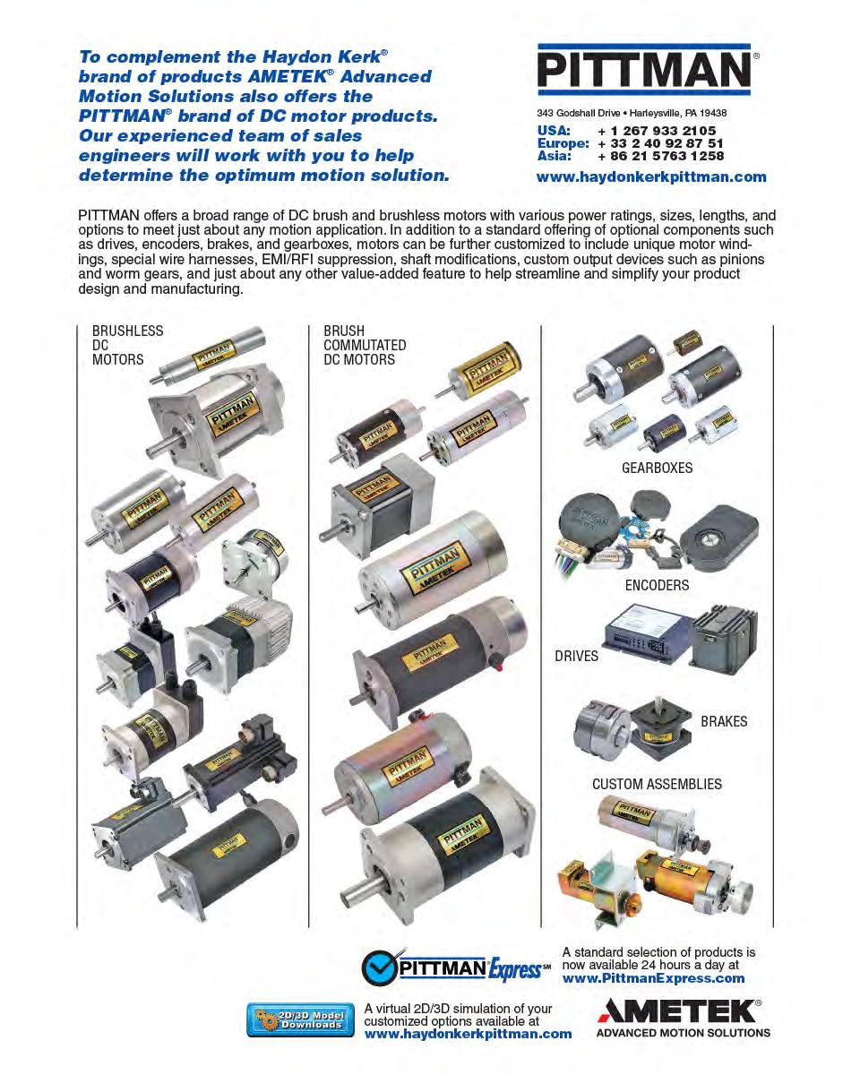
66


67
LINEAR MOTION CATALOG AND DESIGN GUIDE
 WWW.HAYDONKERK.COM LINEAR MOTION CATALOG AND DESIGN GUIDE Providing the technica experience, products, and custom soutions to chaenging motion contro probems Haydon Kerk Motion Soutions is an innovative
--... Need a prototype tomorrow? Experts in customization, innovative design and engineering
 . Hay!J.~!!., kerk " Experts in customization, innovative design and engineering Haydon Kerk Motion Soutions has the e
Thread Direction R = Right hand L = Left hand (Not Available for Micro Series) (Refer to leadscrew. Code. availability)
 (Refer to leadscrew. Code. availability)") Kerk onventiona s: FW Series Free Wheeing Kerk FW Series conventiona stye, without anti-backash function. The Kerk FW Series genera purpose free-wheeing nut is for appications not requiring anti-backash
Kerk onventiona s: FW Series Free Wheeing Kerk FW Series conventiona stye, without anti-backash function. The Kerk FW Series genera purpose free-wheeing nut is for appications not requiring anti-backash
 www.motiontech.com.au Precision Linear Motion Products ataog and Design Guide How to Use This Guide Haydon Kerk Motion Soutions, Inc. speciaizes in customized designs to sove compex engineering probems
Ready for the future. ST 1082 mobile column lifts capacity kg
 Ready for the future ST 1082 mobie coumn ifts capacity 8.200 kg Two hard and fast aws appy in today s maintenance and repair faciities: time is money and an agreement is an agreement. This is why more
Industry. SNR, your guide to linear modules
 Industry SNR, your guide to inear modues SNR A bearing manufacturer known across the word For amost a century SNR has been focusing on the deveopment, design and manufacture of bearings. Today SNR has
Identifying the Motorized RGS part number codes when ordering
 RGS04 Motorized with 28000 Series Size11 DS RGS04 Linear Rail for Hybird 28000 Series Size 11 Double Stacks and RGS04 for 43000 Series Size 17 Single and Double Stacks (See Page 4) RGS04 Linear Rail with
LINEAR MOTION CATALOG AND DESIGN GUIDE
 WWW.YDONKERK.OM LINER MOTION TLOG ND DESIGN GUIDE Providing the technica experience, products, and custom soutions to chaenging motion contro probems aydon Kerk Motion Soutions is an innovative technoogy
Page numbers represent Printed Catalog pages
 Contact Information Contact Information HaydonKerk Motion Solutions TM www.haydonkerk.com North American HQ/Operations Haydon Switch and Instrument 10 Meriden Road Waterbury, CT 06705 Telephone: 203-756-7441
LINEAR MOTION CATALOG AND DESIGN GUIDE
 WWW.YDONKERK.OM LINER MOTION TLOG ND DESIGN GUIDE Providing the technica experience, products, and custom soutions to chaenging motion contro probems aydon Kerk Motion Soutions is an innovative technoogy
Clamping devices. CLAMPEX clamping elements offer new possibilities as a shaft-hub-connection:
 Keyess camping devices Camping devices Genera description: CLAMPEX are keyess camping devices designed to transmit torque via friction on mating components. These designs produce high transmittabe torque
Lintra-Lite Actuators Series A44000, Rodless Cylinders Double Acting
 Section 11 Lintra-Lite Actuators Series A44000, Rodess Cyinders Doube Acting LINTRA -LITE Series A44000 Rodess Cyinders Series A44000 Features...ACT-11-2 Series A44000 Specifications...ACT-11-3 Series
GXL SERIES. DC 2-wire type Micro-size Inductive Proximity Sensor. High performance in micro-size design. Reduced wiring operation. Versatile mounting
 1 DC -wire Micro-size Inductive Proximity SERIES Reated Information Genera terms and conditions... F- Gossary of terms... P.176~ guide... P.71~ Genera precautions... P.179~ PHOTO PHOTO IGHT FOW PARTICUAR
STEPPER DRIVE : E-5042
 54, Annapurna Industria Estate, Tiak oad, E L E C T O N I C S Introduction The E-5042 is a fuy digita stepper drive deveoped with advanced DSP contro agorithm based on the atest motion contro technoogy.
Components for. Overhead Cranes. Sta dard n. Engineered. Hoists. Endtrucks. Crane Kits. Engineered Material Handling
 Engineered Materia Handing Components for Overhead Cranes Sta dard n Hoists Engineered Hoists Endtrucks Crane Kits Troey drive consists of singe speed squirre-cage gear motors. Integra disc brakes are
Haydon Kerk Motion Solutions, Inc. Phone: International:
 Precision Linear Motion Products Catalog and Design Guide How to Use This Guide Haydon Kerk Motion Solutions, Inc. specializes in customized designs to solve complex engineering problems requiring precision
Linear Slot Diffusers Series
 Linear Sot iffusers 5000 Series Linear Sot iffusers 5000 Series The Series 5000 Linear Sot Ceiing iffuser has been speciay designed to provide both the unobtrusive appearance required for architectura
GXL SERIES. DC 2-wire type Micro-size Inductive Proximity Sensor. High performance in micro-size design. Versatile mounting. Reduced wiring operation
 777 PHOTO PHOTO DC -wire Micro-size Inductive Proximity SERIES Reated Information Genera terms and conditions... F-17 Gossary of terms... P.16~ seection guide... P.77~ Genera precautions... P. Conforming
Innovation. Simplicity. is Simply Better. Rotary Lobe Pumps
 Innovation Simpicity is Simpy Better Rotary Lobe Pumps So simpe, yet so diverse. Pease add. Six series with 19 sizes. AL-series PL-series CL-series FL-series EL-series XL-series A pump modes are manufactured
Lead-screw Assemblies
 Lead-screw ssembies 3 Overview of Lead-screw ssembies LED-SREW TENOLOGIES aydon Kerk Motion Soutions, Inc. www.haydonkerk.com Phone: 800.243.2715 Internationa: 203.756.7441 aydon Kerk Motion Soutions products
Drive / Mounting. A = None
 HAYD: 203 756 7441 Motorized and Non-Motorized LRS Linear Rail Systems available with a Haydon Hybrid 43000 Series Size 17 single and double stack linear actuator stepper motor or as an non-motorized linear
The giant amongst the giants.
 BB9090 PLUS 02 BB9090 PLUS The giant amongst the giants. The argest mode of the New Hoand big baer range is the BB9090 PLUS. Its superior performance both in terms of perfect, firm, we-shaped baes as we
Overview. The MicorTIG series at a glance
 www.orch.com.au Overview Lorch, word-eading, new, a in one resonance technoogy that enabes the next generation of portabe machines to operate from mains suppy, sma generators and batteries a deivering
RX10. 5-axis machining center a system developed for high performance. Machine tool manufacturer
 e RX10 5-axis machining center a system deveoped for high performance Machine too manufacturer Minima mass to set in motion The compete machine design has been constructed on the principe of minimising
RX10. 5-axis machining center a system developed for high performance. Machine tool manufacturer
 e RX10 5-axis machining center a system deveoped for high performance Machine too manufacturer 3 2 1 Machine coumn and machine bed made of minera casting 2 Linear roer guide ways 3 Direct measuring system
Any switch configuration
 Series L2 Rotary Cam es Attractive design, reiabe operation and high quaity for any appication up to 25 Amps TIP! Sprecher + Schuh s comprehensive ine of L2 rotary cam switches are avaiabe for a contro
PERFORMANCE AND KNOW-HOW
 Linear and Motion Soutions PERFORMANCE AND KNOW-HOW Nadea represents 50 years of neede and cam foower bearing know-how. Our ong history in design and manufacturing has extended over the years to the products
Blanking tools for the automotive industry
 anking toos for the automotive industry 1736 006 3 rt.-nr..400.03.0706.01000 07/006 17363 00 1 anking toos for the automotive industry Tabe of contents age age FIRO Tradition and Technoogy 6 7 0. 1.. 3.
43M4 n n n n n n. 43L4 n n n n n n. E43M4 n n n n n n. Bipolar 5 VDC 12 VDC. 550 ma 1.3 A 21.9 Ω 3.8 Ω mh mh W Total.
 HAYD: 2 756 744 KERK: 6 2 629 4 Series: Double Stack Stepper Motor Linear Actuator Haydon 4 Series Double Stack hybrid linear actuators offer greater performance. Double Stack Captive Shaft The versatile
EPSM / EPSW. PN Coated End Mills for Machining of Stainless Steels FEATURES. Innovative cutting edge design increases tool life
 EPSM / EPSW PN Coated End Mis for Machining of Stainess Stees FEATURES Innovative cutting edge design increases too ife New PN coating exhibits exceent adhesion and wear resistance EPSM: For both roughing
GStype/HGStype/WGStype
 Tooing News No.E473 Achieving Stabe And Long Too Life With Exceent Chip Evacuation Super MutiDri GStype/HGStype/WGStype 2009-015 series series New J fute Design Achieves Exceent Chip Contro And Stabe Driing
Intelligent Softstarter Controllers
 Inteigent Softstarter Controers Genera escription... 2 Custom Softstarter Panes... 4 Series PCS Controers... 6 Seection Guide... 8 Accessories... 19 Repacement Parts... 21 Technica Information & imensions
Mechanical Level Switches
 Mechanica Leve Switches SOR mechanica eve switches are rugged, industria products specificay designed for versatiity of appication. This cataog contains appication and ordering data for foat and dispaceroperated
Manifold Technology.
 ----------------------------------------------------- 2017.2 Manifod Technoogy. made in Germany I Epkg. unitrything UNDER CONTROL. Manifod Technoogy - I BEULCO heating and cooing manifods made of high-quaity
MarCator 1087 R ABS. Just set once to zero. Battery service life is 3 years. Error free operation
 - -6 MarCator 1087 R The new Digita Indicator MarCator 1087 R. The muti-functiona Digita Indicator with a combined anaog and digita dispay as we as toerance and dynamic measuring functions. Dynamic measuring
Delivering the right solution for you
 Cupboards Deivering the right soution for you The market eader in persona storage soutions for over 30 years, Link ockers is the UK s argest manufacturers of ockers & cupboards. In addition to our diverse
Model TWS. Swirl Diffusers
 Mode TWS Swir Diffusers Mode TWS Advanced Air s new range of high performance TWS ceiing swir diffusers have been designed to deiver the high air change rates required to meet the demand of high oads.
C-Line Linear guide system
 www.bergab.ru adea S.r.. adea GmbH Via Meette, 16 20128 Miano Te. +39 02.27.093.297 Fax +39 02.25.51.768 Internet: www.nadea.it E-Mai: customer.service@nadea.it Rudof-Diese-Straße 28 71154 ufringen Te.
1
 www.systems-sunight.com 1 2 www.systems-sunight.com SUNLIGHT s motive power (traction) batteries motivate your business, as they provide reiabe energy to your industria vehices every day. SUNLIGHT s speciaized
MarCator 1087 ABS USB. No interface box is required! Simple and inexpensive way to set up a multiple measuring. Digimatic. evaluation instrument
 - -46 MarCator 1087 The new Digita Indicator Marcator 1087. The muti-functiona Digita Indicator with a combined anaog and digita dispay; pus toerance and dynamic measuring functions. D y n a m i c m e
CARGO CONNECT COMPACT
 » Connected to you CARGO CONNECT COMPACT Configure on demand, meet changing needs UNITED KINGDOM 02 03 CARGO CONNECT COMPACT Compact, adaptabe transport traier. Adaptabe to meet a vast array of different
A Product of Hard Work SELECTOR GRABS
 A Product of Hard Work SELECTOR GRABS ATTACHMENTS SELECTOR GRABS The perfect partner for your machine Simpe heavy duty design for maximum durabiity and reiabiity Buit in safety features to protect the
CNC INTERNAL GRINDERS
 CNC INTERNAL GRINDERS IG 50 IG 150 IG 150 U WHO WE ARE Estabished in 1973, Micromatic Grinding Technoogies Ltd (MGT ) have been manufacturing a wide range of Externa, Interna, Universa and Specia Purpose
USER INSTRUCTIONS USER INSTRUCTIONS. Innovative Car Alarm. Thatcham M.I.R.R.C. Evaluation No: TC2-1065/0199
 USER INSTRUCTIONS USER INSTRUCTIONS Innovative Car Aarm Thatcham M.I.R.R.C. Evauation No: TC2-1065/0199 IMPORTANT WARNING The Cobra 7928/26/HF Aarm Immobiiser is a Category 1 MIRRC Thatcham isted security
Aluminium Fixed Blade Return Grilles Series
 Auminium Fixed Bade Return Gries 4900 Series Auminium Fixed Bade Return Gries Modes 5145H and 51FH Return Gries have fixed horizonta bades (parae to width/first specified dim.) spaced on 19mm centres with
ASSEMBLY AND INSTALLATION
 ASSEMBY AND INSTAATION STRAIGT AND EVE GUARDRAIING (using Tpes 10, 15, 20, 21, 25 & 26) Where: = distance between centres of uprights I = ength of horizonta tube = distance from ground to centre ine of
Rotary Cam Switches. Rotary Cam Switches
 Rotary Cam es Series... 2 Hande Assembies... 8 Accessories... 12 Circuit Diagrams, Technica Information & Dimensions (Onine)... 13 Series R-Line Rotary Cam es... 24 Handes and Accessories... 27 Circuit
Robotic Automation Industrial Robots Overview
 Robotic Automation Industria Robots Overview 2 Industria Robots 3 The Omron s 5 benefits The new Omron Robotic Automation enhances the most demanding manufacturing ines providing 5 main benefits Performance
Committed to Improving Manufacturing Productivity by delivering Supply Chain Solutions
 Committed to Improving Manufacturing Productivity by deivering Suppy Chain Soutions Bearings Chains Lubricants Gear Boxes Coupings Seas 5 8 High Performance Lubricants Link-Bet SM MB TIDC INDIA (A Unit
ABB Measurement & Analytics. Valve positioners For marine applications
 ABB Measurement & Anaytics Vave positioners For marine appications 2 VALVe positioners For marine appications Vave positioners For the marine industry ABB s industry proven EDP300 and TZIDC positioners
How to Order. Auto switch. Without auto switch (Built-in magnet) Applicable Auto Switches/Refer to p for further details. Indicator.
 Applicable Auto Switches/Refer to p for further details. Indicator.") Compact Side Series MXU How to Order MXU A90V S Compact side Bore size 1 ø ø ø1 1 2 Stroke mm mm 1mm mm 2mm mm Number of auto switches 2 Auto switch S 1 Without auto switch (Buit-in magnet) Appicabe Auto
Compact Side Series MXU How to Order MXU A90V S Compact side Bore size 1 ø ø ø1 1 2 Stroke mm mm 1mm mm 2mm mm Number of auto switches 2 Auto switch S 1 Without auto switch (Buit-in magnet) Appicabe Auto
EH Range Technical Data
 EH Range Technica Data Eectro-hydrauic Vave Actuators Redefining Fow Contro EH Range Technica Data INTRODUCTION The Rotork EH Range of sef-contained, eectro-hydrauic actuator incudes an integrated contro
Swivel and visitor chairs quarterback
 Swive and visitor chairs quarterback Generousy proportioned... Generousy proportioned and eegant the Sedus quarterback is an office swive chair which promises penty of space for productive we-being at
Reach Trucks. and Multi-Way Reach Trucks tonnes. Ready to Perform To Your Applications
 and Muti-Way Reach Trucks Reach Trucks 1.4 2.5 tonnes Ready to Perform To Your Appications Creating Distinction Mitsubishi designed SENSiA a high performance truck (capabe of reaching up to 13m rack height)
IC engine counterbalance trucks
 IC engine counterbaance trucks 7.0 16.0 tonnes quaity reiabiity vaue for money We re here to hep with the heavy ifting Every day, a over the word, peope rey on heavyduty Mitsubishi forkift trucks. In the
LOGIFLEX LF MINI / ELF. Logiflex - flexible handling of goods
 LOGIFLEX LF MINI / ELF Logifex - fexibe handing of goods High fexibiity and efficiency - with ony one truck, goods can be transported, ifted and handed in many different ways. The design puts focus on
c ssupertrak superior cubicle curtain track system
 www.cs-france.fr c ssupertrak superior cubice curtain track system innovative design fexibiity of configuration rigid and durabe smooth and quiet giding SUPERTRAK CUBICLE CURTAIN TRACK KEY FEATURES There
INSTRUCTION MANUAL LITHIUM-ION POLYMER MINI JUMP STARTER (KIT SET) SC POWER SCB22
 SC POWER SCB22") INSTRUCTION MANUAL LITHIUM-ION POLYMER MINI JUMP STARTER (KIT SET) Technica Specifications SCB22 Battery Type: Lithium-Ion Poymer Battery Capacity: 2200 mah (12V DC) Crancking Ampere: 220 A Peak Current:
INSTRUCTION MANUAL LITHIUM-ION POLYMER MINI JUMP STARTER (KIT SET) Technica Specifications SCB22 Battery Type: Lithium-Ion Poymer Battery Capacity: 2200 mah (12V DC) Crancking Ampere: 220 A Peak Current:
Prestolok. Spark resistant push-in fittings for fluids. Catalogue /UK
 Spark resistant push-in fittings for fuids Cataogue 352-/UK Cataogue 352-/UK Index Straight connectors Mae - BSPT Mae - Metric Mae - BSPT Mae - NPTF F23PB - p. C F2PB - p. C F3PB - p. C FPB - p. C Mae
Piston pumps for eff icient wellpoint dewatering
 Piston pumps for eff icient wepoint dewatering PT series P u m p s f o r r e s u t s Innovative eaders for the past 60 years BBA Pumps BV woudn t be a Dutch company if it didn t know how to dea with water!
Spirit TM from Peugeot and Allied Fleet Driving for Perfection. Peugeot Spirit TM
 Spirit TM from Peugeot and Aied Feet Driving for Perfection Peugeot Spirit TM 2 Fuy automatic interna ift Spacious rear compartment High quaity restraint system Passenger comfort Space and Fexibiity Avaiabe
Actros - Specifications
 Pease note: Changes may have been made to the product since the brochure went to press (01.02.2014). The manufacturer reserves the right to make changes to the design, form, coour and specification of
Air nozzles. Air curtains Blowing off and out Cleaning Cooling Drying Reheating Transporting and many others...
 Air nozzes Air curtains Bowing off and out Ceaning Cooing Drying Reheating Transporting and many others Air nozzes As a rue, any fat fan or soid stream nozze can be operated with air instead of iquid However,
Optional Modes of Operation Pump Control Brake Control - Smart Motor Brake, Accu-stop and Slow Speed with Braking
 Controers The Inteigent Controer with extensive starting and stopping configurations up to 1000HP (3-wire), 1400HP (6-wire) The Softstarter Controer provides inteigence, unmatched performance, fexibiity,
Centre Lathes CENTRE LATHES with CSS DRO as standard
 www.cochester.co.uk Centre Lathes CENTRE LATHES with CSS DRO as standard Engineered for efficiency Cochester manua athes are renowned wordwide for quaity and reiabiity. Buit to withstand rugged, heavy
Flat fan nozzles. Nozzle characteristics
 Fat fan nozzes Bet ceaning Coating Steam ceaning Degreasing High pressure ceaning Grave washing Cooing Surface treatment Phosphating Rain curtains Foam contro Foam spraying Lubrication Fiter ceaning ceaning
Precision Ground Plates and Flat Bars. Lifting and Clamping Devices. Ground Precision Components. Elastomer-Bars, -Sheets, -Sections
 A B C D E F G H J K L Die Sets Precision Ground Pates and Fat Bars Lifting and Camping Devices Shanks, ifter studs, eyebots Camping caws, screws and bots Guide eements Ground Precision Components Springs
Procyon 1. Product # Type Date Project Name Project Location Prepared By. Construction. Optical System. Product Applications. l l l. l l l.
 Product # Type Date Project Name Project Location Prepared By Construction Housing is ow copper die-cast auminum, heavy duty, structuray rigid and vibranty dissipating heat for onger umen maintenance ife-hours.
Series. A truly global engine in an ultra-compact package
 400 Series A truy goba engine in an utra-compact package Incrediby compact fexibe and efficient We are committed to meeting our customers needs around the word, which is why the 400 Series is a truy goba
1B20 1B30 1B40. The engineering result of careful market research: Small, light, powerful and universally applicable kw HP.
 The engineering resut of carefu market research: Sma, ight, powerfu and universay appicabe Te: 0 85 3 / 39-0 Fax: 3 94 8 http://www.hatz-diese.de emai: marketing@hatz-diese.de.4-7.7 kw.8-0.5 HP 5 / 629
Our policy is one of continuous research and development. We therefore reserve the right
 Tubing & Hose Metric Nyon, Poyurethane, Poyester Reinforced PVC, Meta Braided Rubber, Copper, Doube Wa Brazed Stee Avaiabe in a variety of different types to suit a wide range of appications A tubing can
<AN002.doc> DALF Application Note #002. Dalf/Simple-H Hookup. Revision 0.02 May 04, 2007
 DALF Appication Note #002 Daf/Simpe-H Hookup Revision 0.02 May 04, 2007 Embedded Eectronics Page 1 5/4/2007 Tabe of Contents 1 APPLICATION NOTE SYNOPSIS...2 2 HOOKUP...2 3 PICTURE (DURING TEST)...3
Connected to you 2019
 2019» Connected to you Fu body ength viny (white traiers ony). Larger main side doors on both sides. 02 03 Standard. Not avaiabe. NCO = no cost option. Change to front nose mouding Now a thin nose section
TANKER T AND TANKER S SERIES
 High Force and Long Strokes TANKER T AND TANKER S SERIES High force in short heights with contact forces to 15,400 bs. Stroke engths to 225 mm Dynamic ubrication extends spring ife Bore sea resists contamination
PRECISION PUMP APPLICATOR
 User s Manua nstaation & Operating nstructions PRECSON PUMP APPLCATOR For Box, Junior, and Custom Appicators For questions and/or product support contact the TW ROCOL North America Customer Service Department
GEAR PUMPS. Displacement from 7 to 51 ccm Pressure up to 260 bar QHD0. Speed from 350 to 3400 RPM
 GEA PUMPS Dispacement from 7 to 51 ccm Pressure up to 260 bar QHD0 Speed from 350 to 3400 PM Gear Pump Cataogue QHD0 TABE OF CONTENTS DESCIPTION......................................................................................................................
NTB Series Nut Assembies. Anti-Backlash Life. Without Kerkote TFE Coating inch / (cm) 100 to 125 million (250 to 315 million) With Kerkote TFE
 100 to 125 million (250 to 315 million) With Kerkote TFE") Screw and Nut Assemblies NTB Nut Series For higher load applications. The NTB Series anti-backlash assembly is designed for higher load applications than the ZBX or KHD series units. Using the specially
Screw and Nut Assemblies NTB Nut Series For higher load applications. The NTB Series anti-backlash assembly is designed for higher load applications than the ZBX or KHD series units. Using the specially
EC Series GMS200C. Generator Set Specification. Your Partner for Power. Page of 5
 EC Series Generator Set Specification Your Partner for Power Page - 1 - of 5 3-Phase, 50Hz@1500RPM Prime Power Standby Power Votage kw kva Amps 380 160 200 303.9 400 160 200 288.7 415 160 200 278.2 440
S.B. 469 for information on GM applications). Both styles are shown in Figure 1. Figure 1
. Both styles are shown in Figure 1. Figure 1") NO: 4263132 SERVICE BULLETIN DATE: January X,1993 Supersedes: S.B. 426R dated 11/7/89 SUBJECT: ZERO-CLEARAN CE GOVERNOR WEIGHT RETAINER ASSEMBLIES In June 1988, Stanadyne introduced a zero-cearance Eastomer
NO: 4263132 SERVICE BULLETIN DATE: January X,1993 Supersedes: S.B. 426R dated 11/7/89 SUBJECT: ZERO-CLEARAN CE GOVERNOR WEIGHT RETAINER ASSEMBLIES In June 1988, Stanadyne introduced a zero-cearance Eastomer
Displacement from 43 to 150 ccm Pressure up to 280 bar Speed from 250 to 3200 RPM GEAR PUMPS QHD2
 Dispacement from 43 to 150 ccm Pressure up to 280 bar Speed from 250 to 3200 PM GEA PUMPS QHD2 Gear Pump Cataogue QHD2 TABE OF CONTENTS BASIC DESCIPTION.............................................................................................................
Displacement from 9 to 31 ccm Pressure up to 280 bar Speed from 500 to 3000 RPM GEAR PUMPS T3S
 Dispacement from 9 to 31 ccm Pressure up to 280 bar Speed from 500 to 3000 PM GEA PUMPS T3S Gear Pump Cataogue T3S TABE OF CONTENTS DESCIPTION......................................................................................................................
600 kva, 600 kw Installation and Operation Manual
 Eaton Power Xpert 9395 High Performance (9395P-600) UPS 600 kva, 600 kw Instaation and Operation Manua For use with Singe UPM (200 600 kva), Two UPM (400 600 kva), and Pus 1 (400 600 kva) UPS Modes Eaton
GEAR PUMPS. Displacement from 10 to 36 ccm Pressure up to 300 bar GHD0. Speed from 350 to 3400 RPM
 GEA PUMPS Dispacement from 10 to 36 ccm Pressure up to 300 bar GHD0 Speed from 350 to 3400 PM Gear Pump Cataogue GHD0 TABE OF CONTENTS DESCIPTION......................................................................................................................
C 60. The new. Giant. milling at its best
 C 60 The new Giant. miing at its best The C 60 U at home in a fieds Too and moud making Highy dynamic simutaneous 5-axes machining up to a component weight of 2,500 kg Aerospace Precision in perfection
Interact Overhead Power
 Interact Overhead Power 75 range introduction feature benefits Interact Overhead Power System is a powertrack catering for singe, 3 phase or dua circuit appications suitabe for standard, permanent ive,
Displacement from 10 to 100 ccm Pressure up to 300 bar Speed from 300 to 3200 RPM GEAR PUMPS QHD1
 Dispacement from 10 to 100 ccm Pressure up to 300 bar Speed from 300 to 3200 PM GEA PUMPS QHD1 Gear Pump Cataogue QHD1 TABE OF CONTENTS DESCIPTION......................................................................................................................
PRECITECH MANUFACTURING PVT. LTD
 www.precitech.in PRECITECH MANUFACTURING PVT. LTD Your Heavy Machining and Fabrication Needs Under One Roof Whoy owned subsidiary of LNV Technoogy Pvt. Ltd. (Member of Sinoma Internationa Engineering Company,
User Manual. 12 Volt Battery Charger THIS MANUAL CONTAINS IMPORTANT SAFETY AND OPERATING INSTRUCTIONS READ ENTIRE INSTRUCTION BEFORE USE
 User Manua 12 Vot Battery Charger Pus Battery maintainer and Rejuvenator THIS MANUAL CONTAINS IMPORTANT SAFETY AND OPERATING INSTRUCTIONS READ ENTIRE INSTRUCTION BEFORE USE Mode No. 60134 / 60138 1 WARNING
perfect body blanks for trouble-free canmaking lines slitters and body blank Technology that keeps you ahead
 perfect body banks for troube-free canmaking ines sitters and body bank transfer units Technoogy that keeps you ahead Sitters body bank transfer systems and Sitters for high precision and fast output.
XTS-W+ Bearing Condition Monitor
 XTS-W+ Bearing Condition Monitor efficient, cost-effective, reevant soutions AMOT has been a pioneering manufacturer of quaity components for marine rotating machinery since 1948 and innovation is something
Blind Rivet Nuts indispensable part modern installation engeneering nearly unlimited fields of applications Honsel-Group
 Bind Rivet Nuts Bind rivet nuts have become an indispensabe part modern instaation engeneering. They aow to insta bot threads of different types into...... thin or ow rigidity components... hoow sections
EP Series WPS150S. Generator Set Specification. Super Quiet, Superior Life! Page of 5
 EP Series Generator Set Specification Super Quiet, Superior Life! Page - 1 - of 5 3-Phase, 50Hz@1500RPM Prime Power Standby Power Votage kw kva Amps 380 120 150 227.9 400 120 150 216.5 415 120 150 208.7
C2 BLUE, C4 BLUE A2 TRANSPORTER, A4 TRANSPORTER STANDARDS RAISED
 » Connected to you C BLUE, C4 BLUE A TRANSPORTER, A4 TRANSPORTER STANDARDS RAISED UNITED KINGDOM 0 03 BLUE THE NEW NAME IN RACE & RALLY PADDOCKS The Bue traier range represents the essence of Brian James
Manual Lathes. The world turns on Colchester lathes
 Manua Lathes With CSS DRO as Standard The word turns on Cochester athes Engineered for efficiency Cochester manua athes are renowned wordwide for quaity and reiabiity. Buit to withstand rugged, heavy
Intelligent Softstarter Controllers
 Inteigent Softstarter Controers Genera escription... 2 Series PCS Controers - escription... 4 Seection Guide... 6 Accessories... 17 Repacement Parts... 19 Technica Information... 20 Wiring iagrams... 24
The DUET Urban Double Deck Trailer
 The DUET Urban Doube Deck Traier Designed for High-Efficiency Urban Deiveries Deivering 200% oad voume to city centres The DUET Urban Doube Deck Traier A high-cube urban freight soution, the DUET Urban
TSP 6500/7000 SERIES. Specifications Turret Trucks
 C TSP 6500/7000 SERIES Turret Trucks C TSP 6500 / 7000 Series Turret Trucks Minimum Cear Aise Running Cearance Non-Teescopic Forks Load Length + 205 + Fork Carriage Offset + Running Cearance + Running
/1505-I-20 TOO L HO L DERS 2015 GM 300
 TO O L H O L D ERS A N D C L A M PI N G D E V I C ES 114 996/1505-I-20 ED I T I O N 2015 TOO L HO L DERS 2015 GM 300 high camping ce PERFECT CONCENTRICITY MAXIMUM OPERATIONAL SAFETY OPTIMAL COOLANT DELIVERY
For use anywhere. Many convenient features
 Controers IN-rai mounted softstarters up to 85A. Larger softstarter frame sizes up to 480A (400HP @480V) Sprecher + Schuh IN-rai mounted Controers can be direct connected to CA7 contactors to provide isoation
Rule No. 16 SERVICE CONNECTIONS, METERS, AND CUSTOMER S FACILITIES
 SOUTHERN CALIFORNIA WATER COMPANY Revised Ca. P.U.C. Sheet No. 3450-W SAN DIMAS, CALIFORNIA 91773-9016 Canceing Revised Ca. P.U.C. Sheet No. 3293-W Page 1 of 7 A. Genera 1. Utiity s Responsibiity a. (1)