Haydon Kerk Motion Solutions, Inc. Phone: International:
|
|
|
- Cornelius Stewart
- 6 years ago
- Views:
Transcription
1

2
3 Precision Linear Motion Products Catalog and Design Guide How to Use This Guide Haydon Kerk Motion Solutions, Inc. specializes in customized designs to solve complex engineering problems requiring precision linear motion. Before using this guide, take a few minutes to review the table of contents and scan through the entire catalog. Lead-screws and Nut Assemblies (Page 11) The lead-screw product line offers an extensive array of non-ball lead-screws, anti-backlash nuts, and free-wheeling nuts for use as components in a motion system. Our precision lead-screws and nuts that easily interface to many types of rotary power sources including stepper motors, servos, brushless DC, brush-type DC, and AC synchronous motors. Lead-screws and nuts are also versatile components in systems requiring combination mechanics such as belt, pulley, lead-screw systems, and folded-over linear actuator designs. Lead-Screws (charts on pages 20 to 24) Nominal screw diameter: 2 mm to 24 mm (5/64-in to 15/16-in) Leads (travel/revolution): 0.3 mm to 76 mm (0.012-in to 3-in)/revolution Nut Styles (product summary and charts on pages 25 to 27) 8 designs of anti-backlash and freewheeling nuts as a function of load and maximum allowable drag torque. PAGE 11 Linear Actuator Stepper Motors (Page 50) The stepper linear actuator product line offers an effective solution that simplifies the conventional way of translating rotary into linear motion. The rotary-to-linear conversion is unique; it takes place within the motor itself therefore eliminating the use of belts and pulleys, rack and pinion and other mechanical components. Hybrid Linear Actuators (Overview on page 69) Footprint: 21 mm to 87 mm (0.8-in to 3.4-in) square Force Output: 2 N to 2200 N (0.5 lb to 500 lb) Linear Travel/step: 1.5 to 127 microns/step ( in to in)/step Can-Stack Linear Actuators (Overview on page 127) Footprint: 15 mm to 46 mm (0.59-in to 1.8-in) diameter Force Output: 7 N to 260 N (1.6 lb to 58 lb) Linear Travel/step: 20 to 400 microns/step ( in to in)/step PAGE 50 Rotary Stepper Motors (Page 171) Haydon Kerk rotary motors are built to provide exceptionally high torque to size ratios. Utilizing a patented enlarged rotor with low inductance coils, the motors provide superior torque and continuous, reliable high performance. Optional rare earth magnets may be specified for even higher torque. Bronze sleeve bearings are standard, ball bearings are also available. Footprint: 20 mm to 46 mm (0.79-in to 1.8-in) diameter Holding Torque: 0.46 N-cm to 11.3 N-cm (0.65 oz-in to 16 oz-in) PAGE 171 Electronic Controller Drives (Page 194) The IDEA family of programmable Stepper Motor Controllers uses an intuitive patent-pending Graphic User Interface (GUI) which greatly simplifies set up and use. Units are available in either USB or RS-485 communication. Haydon Kerk also offers a range of Stepper Motor Non-Programmable Drives controlled with Step, Direction & Enable Commands. These microstepping chopper drives provide a simple solution for production volumes. PAGE 194 Motorized and Non-Motorized Linear Rails and Slides (Page 202) The linear rails and slides product line should be considered when a more extensive linear motion solution is desired to minimize overall system material cost, engineering time, and assembly cost. The linear rails and slides are complete mechanical systems that can be powered and motorized to include a linear bearing, rotary bearings, mechanical frame, precision screw and nut, and an electronic drive unit. We can also design, engineer and manufacture a multiple-axis configuration specific to your application requirements. Travel distances (stroke lengths): Up to 90-in (229 cm) PAGE 202 ScrewRails, Spline Shafts and Guide Rails (Page 247) Kerk ScrewRail combines both functions in a single, coaxial component. The design saves as much as 80% of the space used by a two-rail system. Kerk Spline Shafts provide anti-rotation for one axis motion or a drive mechanism with rotation for two axes of motion. 1 PAGE 247
4 Contact Information Contact Information Haydon Kerk Motion Solutions, Inc. North American HQ/Operations Haydon Kerk Motion Solutions, Inc. Haydon Products Division 1500 Meriden Road Waterbury, CT USA Telephone: info.haydonkerk@ametek.com Haydon Kerk Motion Solutions, Inc. Kerk Products Division 59 Meadowbrook Drive Milford, NH USA Telephone: info.haydonkerk@ametek.com Asia Operations Haydon Linear Motors Co., Ltd. Xianlong Industrial Park No. 110, Lane 4, Xinyuan Road New District, Changzhou, China Telephone: / Sales: / info.haydonkerk@ametek.com.cn India Operations AMETEK Instruments India Pvt. Ltd. Haydon Kerk and Pittman Motor Sales 148 Prestige Featherlite Tech Park EPIP Phase II, Whitefield Bangalore , India (Telephone) (Mobile) dinesh.dhananjayan@ametek.com Europe Operations Haydon Kerk Motion Solutions / France 57 rue des Vignerons Coueron - France Telephone: info-europe.haydonkerk@ametek.com Haydon Kerk Motion Solutions / Germany Schmiedstr Lauf a.d. Pegnitz - Germany Telephone: info-europe.haydonkerk@ametek.com Haydon Kerk Motion Solutions, Inc. All rights reserved. This catalog was produced for exclusive use by customers of Haydon Kerk Motion Solutions, Inc, a division of AMETEK, Inc. No part of this book or technical information can be used, reproduced or altered in any form without approval or proper authorization from Haydon Kerk Motion Solutions, Inc., AMETEK, Inc., and its global affiliates. This catalog is intended to be a guide for products and services offered by Haydon Kerk Motion Solutions, Inc. Despite taking all precautions to avoid technical or typographical errors within the catalog some errors may exist. Because most of our products involve a high degree of accuracy and precision we strongly recommend that you contact a Haydon Kerk Motion Solutions technical advisor for more details and specific application requirements. APR
5 Table of Contents Company Overview Who We Are Custom System Solutions Lead-Screws and Nut Assemblies Lead-Screws Anti-Backlash Nuts Lead-screw and Nut Overview Anti-Backlash Technology Lubrication Kerkote Black Ice Materials 303 Stainless Steel Kerkite Composite Polymers Special Materials Design and Engineering Data Part Number Construction Lead-Screw Size List Lead-Screw Nut Styles Nut Feature Matrix Product Comparison Chart CMP Series ZBX Series includes Mini and Micro Series KHD Series WDG Series NTB Series includes Mini Series VHD Series ZBA Series NTG Series includes Mini Series Free-Wheeling and Specialty Nuts BFW Series includes Mini and Micro Series DP Series Custom Nuts
6 Table of Contents Stepper Motor Linear Actuators Product Summary Standard End Machining Lubrication Options Stepper Motor Tutorial Resonance Drives Summary and Terminology Hybrid Linear Actuators Product Overview Wiring/Stepping Sequence Series (Size 8) Single Stack Series (Size 8) Double Stack Series (Size 11) Single Stack Series (Size 11) Double Stack Series (Size 14) Single Stack Series (Size 14) High Resolution Series (Size 14) Double Stack Series (Size 17) Single Stack Series (Size 17) High Resolution Series (Size 17) IDEA Programmable Drive Series (Size 17) Double Stack Series (Size 17) Double Stack IDEA Drive Series (Size 23) Single Stack Series (Size 23) High Resolution Series (Size 23) Double Stack Series (Size 34) Accessories and Options Integrated Connectors Encoders Home Position Switch Proximity Sensor TFE Option Integrated Anti-Backlash Nut Dual Motion: Combined Linear and Rotary Actuator Series (Size 14) Dual Motion Series (Size 17) Dual Motion
7 Table of Contents Can-Stack Linear Actuators Product Overview Wiring/Stepping Sequence G4 Series: High Performance Series (Ø 20 mm) TFE Coated Lead-screws Home Position Switch End of Stroke Proximity Sensor Series (Ø 25 mm) TFE Coated Lead-screws Home Position Switch Encoder End of Stroke Proximity Sensor Series (Ø 36 mm) TFE Coated Lead-screws Home Position Switch Encoder End of Stroke Proximity Sensor Series (Ø 15 mm) Z20000 Series (Ø 20 mm) TFE Lead-screws, High Temp, Position Switch, Proximity Sensor..... Z26000 Series (Ø 26 mm) TFE Lead-screws, High Temp, Position Switch, Proximity Sensor Series (Ø 36 mm) Series (Ø 36 mm) High Resolution TFE Lead-screws, High Temp, Position Switch, Proximity Sensor Series (Ø 46 mm) TFE Lead-screws, High Temp, Position Switch, NEMA Flange Assembly Can-Stack Rotary Actuators Product Overview Wiring/Stepping Sequence Z20000 Rotary Series (Ø 20 mm) Rotary Series (Ø 26 mm) Z26000 Rotary Series (Ø 26 mm) Rotary Series (Ø 36 mm) Rotary Series (Ø 46 mm) Low Profile Pancake Rotary Actuators Pancake Rotary Planetary Gear Train (Ø 80 mm)
8 Table of Contents AC Synchronous Actuators AC Synchronous Hybrid Actuators AC Synchronous Can-Stack Actuators AC Synchronous Rotary Actuators Stepper Motor Drives IDEA Programmable Drives PCM4806E / PCM4826E ACM4806E / ACM4826E DCM4826X Pulse/Direction/Enable Drive DCM8027 & DCM8054 Micro-Stepping Drives DCS4020 Bipolar Chopper Drive Whisper Drive Motorized and Non-Motorized Linear Rails and Slides Product Overview Linear Rail Application Checklist BGS Series Linear Rails Overview Selector Chart Motorized BGS Series (Size 11) Hybrid Double Stack Series (Size 17) Hybrid Single Stack Series (Size 17) Hybrid with IDEA Drive Motorized BGS Series (Size 17) Hybrid Single/Double Stack Series (Size 17) Hybrid with IDEA Drive Motorized BGS Series (Size 23) Hybrid Single/Double Stack RGS Series Linear Rails Overview Selector Chart Motorized RGS Series (Size 11) Hybrid Double Stack Series (Size 17) Hybrid Single/Double Stack and IDEA Drive.. Non-Motorized RGS04 Without motor, with guide screw - or - without guide screw Motorized RGS06 and RGW06 (Wide base with Guide Tracks) Series (Size 17) Hybrid Single/Double Stack Series (Size 17) Hybrid Single/Double Stack with IDEA Drive Series (Size 23) Hybrid Single/Double Stack Non-Motorized RGS06 and RGW06 Without motor, with guide screw - or - without guide screw
9 Table of Contents RGS Series Linear Rails Motorized RGS08 and RGW Series (Size 23) Hybrid Single/Double Stack Non-Motorized RGS08 and RGW08 Without motor, with guide screw Motorized RGS10 and RGW Series (Size 23) Hybrid Single/Double Stack Non-Motorized RGS10 and RGW10 Without motor, with guide screw - or - without guide screw WGS Linear Rail Systems Motorized WGS Series (Size 17) Hybrid Single/Double Stack Series (Size 17) Hybrid Single/Double Stack with IDEA Drive Series (Size 23) Hybrid Single/Double Stack Non-Motorized WGS06 Without motor, with guide screw LRS Linear Rail Systems Motorized LRS Series (Size 17) Hybrid Single/Double Stack (IDEA Drive option) 244 Non-Motorized LRS Without motor, with guide screw - or - without guide screw ScrewRail Linear Actuators Overview SRA Series: General Purpose SRZ Series: Anti-Backlash End Supports SRA Selector Chart SRZ Selector Chart Spline Shafts, Rails and Bushings, Guides Spline Shafts Rails and Bushings Linear Rail Checklist Linear Rail Application Checklist Form

10 Who We Are Recognized as a leader in motor miniaturization, Haydon Products Division has been building electric motors and stepper motor based linear actuators for almost half a century. The company s manufacturing facility, located on ten acres in the heart of Connecticut, supports today s most efficient technology and manufacturing methods and is ISO 9001 certified. Kerk Products Division was established in 1976 and has grown to be one of the world s largest exclusive manufacturers of non-ball lead-screws, linear rails, and actuator systems. Our internationally acclaimed anti-backlash designs and materials provide high accuracy, unsurpassed repeatability, and long life in a full range of motion control applications. Haydon Kerk Motion Solutions is headquartered in Waterbury, CT, with additional manufacturing operations in Milford, NH, and Changzhou, China. Haydon Kerk also has facilities in Germany and a technical center in Coueron, France. Haydon Kerk Motion Solutions linear motion products are used in much of today s sophisticated medical equipment, laboratory instrumentation, machinery automation, aerospace, analytical equipment, computer peripherals, semiconductor industries, and other applications that require precision motion. Whether an application requires a standard item, custom design, new product, or a more sophisticated complete assembly, Haydon Kerk Motion Solutions experienced engineering team will assist you. MEDICAL ANALYTICAL AND SURGICAL EQUIPMENT INDUSTRIAL AUTOMATION AMETEK is a global leader in electronic instruments and electromechanical devices with colleagues at numerous manufacturing, sales and service locations in the US and in many other countries around the world. AMETEK consists of 2 operating groups: Electronic Instruments and Electromechanical. Electronic Instruments is a leader in advanced instruments for the process, aerospace, power, and industrial markets. Electromechanical is a differentiated supplier of electrical interconnects, specialty metals, and technical motors and associated systems, as well as a leader in floor care and specialty motors. SEMICONDUCTOR FABRICATION BOTTLING AND FOOD PROCESSING EQUIPMENT We take pride in our expertise in customizing products for specific application needs. 8
11 Custom System Solutions We offer high precision motion systems at any level of sophistication and integration, providing all necessary mechanical, electrical and software supply and support. Single-axis and multiple-axis systems are our expertise, either using our own components or custom designed to our clients specifications. We are able to configure motion systems utilizing our own component level supply. Clients realize singlesource supplier efficiency and fully tested solutions through our extensive in-house resources... Mechanical, electrical and software engineering teams Full inspection and testing capabilities (includes interferometry, vision inspection, environmental, vibration and noise testing). All operations are ISO Certified and RoHS Compliant. Proprietary and patented products and processes that include low friction coatings, in-house developed polymers. Extensive manufacturing capabilities including in-house tool design and fabrication, injection molding, EDM, 3D printing, coating and cabling. Custom motor designs such as axial flux motors. Linear Mechanics with virtually unlimited assembly options. We have single and multi-axis solutions as well as Z-theta. Drives & Electronics, integrated or stand-alone stepper drives, as well as software and servo drives. Development And Design Engineers Our experience starts with the design of the basic components and expands into the integration of these components for the right solution to your motion needs. Experts in medical device and surgical tool applications Meeting requirements of FDA, Qualification, Documentation Complete range of lab test OEM options Specialized industrial application capability Manufacturing Professionals Because we manufacture at the component level it allows us to responsibly fully evaluate all aspects of a tested system. Designed for manufacturablility, repeatability and reproducibility Custom testing to mimic application Ongoing technical support after development cycle OEM Purchasing and Business Managers A single source for a complete system to simplify your vendor base and reduce inventory costs. We can help decrease unnecessary labor and materials that can bring production cost savings. Engineering / Development Managers Ever increasing efficiency demands can make new projects difficult to finish on budget and on time. If your team is lacking expertise in a certain area of motion control, we have the experienced engineers to help fill the voids. Receive individual attention from the single point contact of a small, focused and strategically aligned group, backed by the resources and support of a global corporation. 9

12 Lead-screw Assemblies

 to 15/16-in (23 mm), with standard leads from.012-in to almost 4-in (0.")
13 Overview of Lead-screw Assemblies Haydon Kerk Motion Solutions products have been designed specifically for motion control applications. They are not compromised adaptations of general purpose screws or nuts. The screw thread form is designed for maximum life, quiet operation, and compatibility with Haydon Kerk Motion Solutions anti-backlash nut designs. LEAD-SCREW TECHNOLOGIES KERK LEAD-SCREWS are available in standard diameters from 5/64-in (2 mm) to 15/16-in (23 mm), with standard leads from.012-in to almost 4-in (0.30 mm to 92 mm) including hard metric and left hand threads. Custom sizes and leads can be special ordered. Most stock screws are manufactured from 303 stainless steel and are produced with Haydon Kerk Motion Solutions exclusive precision rolling process. Other materials are available on special order. Positional bi-directional repeatability (with Kerk anti-backlash nut) is within 50 micro-es (1.25 micron) and standard lead accuracy is better than in./in. (mm/ mm). Lead accuracies are available to.0001-in./in. (mm/mm). Haydon Kerk Motion Solutions total in-house manufacturing and quality control assure uniform and consistent products. KERK NUTS are available in 8 standard anti-backlash designs (CMP, ZBX, WDG, NTB, KHD, VHD, NTG, ZBA); general purpose BFW Series plus the Mini Series. (See Product Comparison Chart for size availability). Custom nut configurations and mountings are also readily available. The Kerk brand anti-backlash designs provide assemblies which are wear compensating with low frictional drag and exceptional positional repeatability. Operation to more than 300 million es of travel can be achieved. Haydon Kerk Motion Solutions provides nuts in a wide range of wear resistant, self-lubricating thermoplastic materials. 11
14 Lead-screw Assemblies: Anti-Backlash Technologies LEAD-SCREW TECHNOLOGIES Axial Take-up Mechanism The standard method for taking up backlash is to bias two nut halves axially using some type of compliant spring. (Wavy washer, compression spring, rubber washer, etc.) NUT HALF SPRING PRELOAD NUT HALF The unit is very stiff in the direction in which the nut half is loaded against the flank of the screw thread. However, in the direction away from the screw thread, the nut is only as axially stiff as the amount of preload which the spring exerts. NUT HALF SPRING FORCE LOAD AGAINST SCREW FLANK For example, if the maximum axial load to which the system is subjected is 50 lbs., the amount of spring preload must be equal to, or greater than, 50 lbs. in order to maintain intimate screw/nut contact. The problems arising from preloading in this manner are increased drag torque and nut wear. Obviously, the higher the load at the screw/nut interface, the higher the required torque to drive the nut on the screw and the more susceptible the unit is to nut wear. An alternate method replaces the spring with a stiff spacer sized to fit exactly between the two nut halves. NUT HALF (L) STIFF SPACER NUT HALF There is no excessive preload force at the interface and the unit is capable of carrying high axial loads in either direction with no backlash. This is fine initially. However, as use time increases, wear begins on the nut threads causing a gap to develop between the spacer (L) and the nut halves. 1 2 NUT HALF (L) NUT HALF This gap ( 1 + 2) is now the amount of backlash which has developed in the unit. This backlash can be removed by replacing the stiff spacer with a new spacer equal to (L ). This process, although effective, would be extremely costly and difficult to implement on a continuous basis. The Solution What is needed, then, is a stiff spacer which will continually expand to accommodate the wear which occurs during use. This is done by creating a spacer threaded at one end with a complimentary nut torsionally biased to advance when a gap develops. C The thread at the end of the spacer is a fine helix such that an axial load will not backdrive the nut once spacer growth has occurred. L The preload on the unit is only the amount necessary to turn the spacer nut on the spacer rod and is independent of the external system loadings. We thus have a self-wear compensating unit which has extremely low frictional drag torque yet high axial stiffness. C L

15 Lead-screw Assemblies: Lubrication Kerkote and Black Ice TFE Coatings Haydon Kerk Motion Solutions, Inc. offers multiple options for lubrication. All Kerk lead-screw nuts feature self-lubricating polymers. When maximum performance is required, Kerkote and Black Ice TFE coatings provide unmatched results in the most demanding applications. LEAD-SCREW TECHNOLOGIES The purpose of TFE coating is to supply a more even distribution of lubricant than is normally found when using standard self-lubricating plastics on steel. The wear life, coefficient of friction and resulting torque to drive a lead-screw assembly are highly governed by the ability of the engineered plastic to supply sufficient lubrication to the nut/ screw interface. The inability of the internal lubricating agents in some plastics to consistently migrate to the surface may result in erratic drag torques and unpredictable wear. Kerkote TFE Coating Kerkote TFE coating covering the entire screw surface results in an extremely even lubrication distribution. Test results indicate system torque requirements are consistently low with little or no change in required frictional driving torque, even with changes in motor R.P.M. Haydon Kerk Motion Solutions has developed a custom composition Kerkote TFE specifically for our lead-screw and nut materials. It is applied using an automated process and provides extended nut life and smooth operation with little additional cost. Kerkote TFE is a soft coating, a long-term dry lubricant that is optimized for softer plastics like acetals and nylons, with or without mechanical reinforcement. Lubrication to the nut/screw interface occurs by the nut picking up Kerkote TFE particles from the coating as well as from the migration of the internal lubricant within the plastic nut. Although care is taken to ensure that chips and voids do not occur in the coating, small voids have been shown to have no effect on system performance. The transfer of TFE to the nut continues throughout the operating life of the assembly as long as the nut periodically travels over areas with Kerkote TFE coating. The lubricant, although solid, also has some spreading ability as in fluid lubricants. Kerkote TFE coated screws provide the maximum level of self-lubrication and should not be additionally lubricated or used in environments where oils or other lubricant contamination is possible. Black Ice TFE Coating Black Ice TFE coating shares many of the benefits of Kerkote TFE but, in contrast, is a hard coating that offers exceptional durability in all types of environments, with virtually any type of polymer nut. Black Ice TFE coating remains on the screw, offering a low friction surface upon which the nut travels. Rather than acting as a dry lubricant, Black Ice TFE is an anti-friction coating whose surface properties displace the metal to which it is applied. Though it is not intended for use with metal or glass fiber reinforced nuts, Black Ice TFE is bonded securely to the screw s surface and can withstand abrasion from contamination, rigid polymer systems, fluid impingement and wash down applications. Black Ice TFE can be used in the presence of more aggressive environment conditions, or anywhere reduced friction and a permanent coating is desired. Both Kerkote and Black Ice TFE coatings offer the advantages of dry lubrication. These are maintenance-free coatings that are designed to last the life of the product. They are intended to be used without additional lubricants, thereby further increasing the value of Kerk lead-screw assemblies through elimination of the most common failure of screw driven drives, lubrication failure. There are certain applications where external lubrication may be desired. These include the use of nut materials such as glass reinforced plastic or metal. Greases, when used properly can provide unique capabilities and Haydon Kerk Motion Solutions does offer a selection of greases developed specifically for these applications. Please contact a sales engineer for assistance selecting the best lubricant for your requirements. 13


16 Lead-screw Assemblies: Materials LEAD-SCREW TECHNOLOGIES 303 Stainless Steel Kerk brand lead-screws and linear rails start with premium grade 303 stainless steel. Haydon Kerk Motion Solutions, Inc. has identified the material properties most critical for producing the very high quality rolled steel screws in the world and controls these to levels unmatched in the industry. Because of our leadership position, we are able to utilize this exceptional quality steel without having to charge premium prices. Kerk stainless steel lead-screws and guide rails are corrosion resistant, non-magnetic, and compatible with many demanding processes. The ideal starting point for a maintenance-free product, this premium quality stainless steel is being used in numerous applications including medical applications, clean rooms, food and human contact, salt spray, cryogenics and vacuum. Kerkite Composite Polymers In addition to the Kerk self-lubricating acetal nut material, Haydon Kerk Motion Solutions offers a variety of custom compounded Kerkite composite polymers. Kerkite polymers are a family of high performance materials that offer exceptional wear properties with the cost and design advantages afforded through injection molding. Kerkite polymers offer a variety of mechanical, thermal and electrical properties and are compatible with many chemicals and environmental conditions. Kerkite Composite Polymers are available options for most Kerk Lead-screw Nuts and are standard materials for Linear Rail and Spline Shaft bushings, RGS Carriages and Screwrail Bushings and End Supports. Each member of the Kerkite family is compounded with lubricants, reinforcements and thermoplastic polymers formulated to provide optimum performance in its target conditions and applications, resulting in superior performance and extended life. A cornerstone of the Haydon Kerk Motion Solutions advantage is design flexibility. Kerkite Composite Polymers, along with our injection molding and mold making capabilities, offer huge design advantages and cost savings compared with non-moldable materials. Kerkite high performance polymers outperform other plastics and outlast metal bushings and bearings. When combined with Kerkote or Black Ice TFE coatings, Kerkite Composite Polymers have been shown to provide hundreds of millions of es of travel in customer applications while continuing to maintain precise, accurate motion and positioning. Special Materials In addition to the Kerk standard material 303 stainless steel, self lubricating acetal and Kerkite high performance composite polymers we also work with a vast array of custom materials. Kerk has rolled screws in many other materials, including 316 stainless, 400 series stainless, precipitate hardening materials, carbon steel, aluminum, and titanium. Kerk nuts had been produced in many alternative plastics including PEEK, polyester, Torlon, Vespel, PVDF, UHMW, Ertalyte and customer-supplied specialty materials. We have also provided metal nuts made from bronze, brass, and stainless steel. With so much flexibility in our manufacturing process, if the material can be molded, machined, ground, or rolled, Haydon Kerk Motion Solutions can likely process it using state of the art machine tools, injection molding and mold making, grinding and thread rolling equipment. Haydon Kerk Motion Solutions excels at supplying the best overall solution to meet our customers requirements. Contact Haydon Kerk Motion Solutions to find out how you can benefit from these choices. 14
17 Lead-Screw Assemblies: Design & Engineering Data Design and Engineering Data Screw Accuracy Haydon Kerk Motion Solutions, Inc uses a unique precision rolling process for screw manufacturing. Standard lead accuracy for Kerk screws is.0006 in./in. (mm/mm). Lead accuracies are available up to.0001 in./in. (mm/mm). Please consult the factory for higher lead accuracies. Assemblies have an extremely high bi-directional repeatability of 50 micro-es (1.25 micron). LEAD-SCREW TECHNOLOGIES End Machining Haydon Kerk Motion Solutions can custom machine screws to your specifications or provide cut-to-length screws for your own machining. Critical Speed This is the rotational speed at which a screw may experience vibration or other dynamic problems. See CRITICAL SPEED CHART to determine if application parameters result in speed approaching critical. To minimize critical speed problems: use a longer lead, choose a larger diameter or increase bearing mount support. Lengths Lengths can be specified up to 12 ft. (4M) from stock, (depending on diameter and lead). Cut to length screws are offered in 6-in increments (6-in, 12, 18,...) +1.0-in/-0-in. Lead Advancement per revolution. All screws are listed by lead, not pitch. Lead = Pitch x Number of Starts Pitch Crest-to-crest distance or one divided by threads per. (On a multiple start thread, the pitch equals the lead divided by the number of starts.) 15
18 Lead-screw Assemblies: Design & Engineering Data LEAD-SCREW TECHNOLOGIES Traverse Speed The nut materials we use provide long wear-life over a wide variety of conditions. However, very high loads and/or speeds will accelerate nut wear. Special materials may be required for these situations. We offer the following guidelines for continuous duty linear traversing speeds for optimum life: Lead Traverse Speed Lead Traverse Speed 1/10-1/2-in 4-in/sec. 1/2-1-in 10-in/sec /2-in 30-in/sec mm 100 mm/sec mm 250 mm/sec mm 760 mm/sec. Maximum Load Although the Kerk Anti-Backlash Assemblies are capable of withstanding relatively high loads without catastrophic failure, these units have been designed to operate under the loading shown in the size charts. Efficiency Efficiency is the relationship of work input to work output. It should not be confused with mechanical advantage. Listed efficiencies are theoretical values based on Kerkote TFE coated screws. Torque The required motor torque to drive a lead-screw assembly is the sum of three components: the inertial torque, drag torque, and torque-to-move load. It must be noted that this is the torque necessary to drive the lead-screw assembly alone. Additional torque associated with driving frictional bearings and motor shafts, moving components, and drag due to general assembly misalignment must also be considered. Inertial Torque: T j = I α Where I = screw inertia α = angular acceleration Drag Torque: The Kerk Anti-Backlash Assemblies are typically supplied with drag torque of 1 to 7 oz.-in. The magnitude of the drag torque is dependent on the standard factory settings or settings specified by the customer. Generally, the higher the preset force, the better the Anti-Backlash characteristics. Torque-to-Move: T L = LOAD x LEAD 2p x EFFICIENCY Back Driving Sometimes referred to as reversibility, back driving is the ability of a screw to be turned by a thrust load applied to the nut. Generally, back driving will not occur when the screw lead is less than 1/3 the diameter for uncoated screws or 1/4 the diameter for Kerkote TFE coated screws. For higher leads where back driving is likely, the torque required for holding a load is: LOAD x LEAD x BACKDRIVE EFFICIENCY T = b 2p Screw Straightness Screw straightness is measured as Total Indicator Runout(TIR). The standard straightness for lead-screws is.003-in/ft. Haydon Kerk Motion Solutions can provide tighter specifications on customer request. All screws are hand straightened before shipping. 16
19 Lead-screw Assemblies: Design & Engineering Data Mechanical Properties Screw Inertia Screw Size Screw Inertia (oz- sec 2 /) (g-cm 2 /cm) 5/64 (2) 3.4 x x /8 (3.2) 1.8 x x /64 (3.5) 3.4 x x /32 (3.97) 4.9 x x /16 (4.76) 1.1 x x /32 (5.55) 1.8 x x /4 (6) 3 x x /16 (8) 5 x /8 (10) 1.5 x /16 (11) 3.5 x /2 (13) 5.2 x /8 (16) 14.2 x /4 (19) 30.5 x /8 (22) 58.0 x /16 (24) 73.0 x Anti-Backlash Life Without Kerkote TFE Coating Series (cm) 40 to 60 million CMP (100 to 150 million) 5 to 10 million ZBA (12 to 25 million) 40 to 60 million ZBX (100 to 150 million) 80 to 100 million KHD (200 to 250 million) 100 to 125 million WDG (250 to 315 million) 100 to 125 million NTB (250 to 315 million) 200 to 225 million VHD (500 to 570 million) N/A, Typical Backlash BFW.003 to.010 (.076 to.25) 5 to 10 million NTG (12 to 25 million) With Kerkote TFE Coating (cm) 150 to 200 million (380 to 500 million) 15 to 40 million (38 to 100 million) 150 to 200 million (380 to 500 million) 180 to 230 million (450 to 580 million) 200 to 250 million (500 to 635 million) 200 to 250 million (500 to 635 million) 300 to 350 million (760 to 880 million) N/A, Typical Backlash.003 to.010 (.076 to.25) 15 to 40 million (38 to 100 million) Anti-backlash life is defined as the nut s ability to compensate for wear while maintaining its zero backlash properties. Above life data is based on 25% of the dynamic load rating. NTB style does not include mini series sizes. Life will vary with loading, operating environment, and duty cycle. The longer screw leads generally provide longer life. Mechanical Properties Lead-screw LEAD-SCREW TECHNOLOGIES Material Surface Finish Dimensional Tolerances Inch Metric.X ±.02 L < 4 ± 0.1.XX ± < L 16 ± 0.15.XXX ± < L 63 ± < L 250 ± 0.3 Grease Compatibility Chart Nut Type Grease CMP Yes ZBX Yes ZBA Yes KHD No VHD No WDG No BFW Yes NTB No NTG Yes Lubrication Coatings Kerkote Black Ice Yes Yes Yes Yes Yes Yes Yes Yes Yes Yes Yes Yes Yes Yes Yes Yes Yes Yes Stainless Steel (options available) Nuts Material Better than 16 micro-es (0.4 µm) Tensile Strength Polyacetal with 9,700 psi Lubricating Additive Other Kerkite materials available Assembly Standard Operating Temp. Range F* (0-93 C)* Coefficient of Expansion 6.0 x 10 5 in/in/ F Coefficent of Friction Polyacetal Nut to Screw Static =.08 Dynamic = **.09 ** * Very high or low temperatures may cause significant changes in the nut fit or drag torque. Please call Haydon Kerk Motion Solutions for optional temperature range materials. ** with Kerkote TFE Coating
20 Lead-screw Assemblies: Standard End Machining LEAD-SCREW TECHNOLOGIES Standard End Machining Dimensions = mm [es] Cross Drilled Hole Turned Journal Hex Drive End Male Thread Square End Female Thread Single Flat Screwdriver Slot Double Flat Standard Break Edge Ground Journal 18
 including metric and left hand threads. Custom sizes and leads can be special ordered.")
21 Lead-screw Assemblies: How to Order Lead-screws Kerk Lead-screws KERK LEAD-SCREWS are available in standard diameters from 1/8-in (3.2mm) to 15/16-in (23mm), with standard leads from.012-in to almost 4-in (0.30mm to 92mm) including metric and left hand threads. Custom sizes and leads can be special ordered. Most stock screws are manufactured from 303 stainless steel and are produced with Haydon Kerk Motion Solutions exclusive precision rolling process. Other materials are available on special order. Positional bi-directional repeatability (with Kerk anti-backlash nut) is within 50 micro-es (1.25 micron) and standard lead accuracy is better than in./in. (mm/mm). Lead accuracies are available to.0001-in./in. (mm/mm). Please consult factory for more details. Haydon Kerk Motion Solutions total in-house manufacturing and quality control assure uniform and consistent products. LEAD-SCREW ASSEMBLIES Identifying the part number codes when ordering ZBX T K R XXXX Prefix: LSS (Screw Only) Nut Series CMP ZBX WDG NTB KHD VHD NTG ZBA BFW ZBM Nut Mounting Style A = Flanged (Triangular) F = Flanged (Round) P = Flange (Triangular with pilot) T = Threaded S = Screw only For Micro and Mini Nuts Only: B = Barrel R = Rectangular Lubrication S = Uncoated K = Kerkote TFE Coating G = Grease HSS-17 Standard N = Nut only Thread Direction R = Right hand L = Left hand B = Right and Left hand (Refer to leadscrew charts for availability) Diameter Code (Refer to lead-screw charts, pages 20 to 24) Nominal Thread Lead Code (Refer to leadscrew charts, pages 20 to 24) Unique Identifier Proprietary suffix assigned to a specific customer application. The identifier can apply to either a standard or custom part. For immediate availability cut-to-length screws, check our ecommerce site at haydonkerkexpress.com EXAMPLES: LSSSSR = Lead-screw only, uncoated, right hand thread, 1/4-in nominal screw diameter, thread lead, without an assigned unique identifier WDGABR XXXX = Assembly: WDG Series Nut, triangular flanged mount, Black Ice TFE coating, right hand thread, 3/8-in nominal screw diameter, thread lead, without an assigned unique identifier ZBXTKR XXXX = Assembly: ZBX Series Nut, thread mounting, Kerkote TFE coating, right hand thread, 7/16-in nominal screw diameter, thread lead, without an assigned unique identifier Special environments (temperature, clean room, contaminents, etc.) For applications assistance or order entry, call your the Haydon Kerk Motion Solutions Engineering at NOTE: Not all thread leads are available in all screw diameters New nuts and leads are continually being added. Contact Haydon Kerk Motion Solutions for latest availability. 19
22 Lead-screws: Lead-screw Size List Lead-screw Size List Diameter (es) Diameter Code Lead (es) LEAD CODE Left Hand Available Outside Diameter (for Reference) (es) Root Diameter (for Reference) (es) Efficiency %* Compatible Nut Styles LEAD-SCREW ASSEMBLIES 5/64 1/ l LH Only ** 30** 36** 52** 66** BFW ZBM 3DP NTB NTG BFW DP NTB NTG BFW 9/ DP NTB NTG BFW 5/ l LH Only DP NTB NTG BFW 3/ l DP CMP WDG NTB NTG BFW 7/ l DP WDG NTB NTG BFW Shaded areas have been translated from their designed or mm dimension to an equivalent mm or dimension. 20 * Listed efficiencies are theoretical values based on Kerkote TFE coated lead-screws ** Listed efficiencies for Micro screws are theoretical values based on non-coated lead-screws
23 Lead-screws: Lead-screw Size List Lead-screw Size List Diameter (es) Diameter Code Lead (es) LEAD CODE Left Hand Available Outside Diameter (for Reference) (es) Root Diameter (for Reference) (es) Efficiency %* Compatible Nut Styles 1/ l l l l DP CMP ZBX ZBA WDG NTB NTG BFW LEAD-SCREW ASSEMBLIES 5/ CMP ZBX ZBA KHD WDG NTB NTG BFW Shaded areas have been translated from their designed or mm dimension to an equivalent mm or dimension. *Listed efficiencies are theoretical values based on Kerkote TFE coated lead-screws 21
24 Lead-screws: Lead-screw Size List Lead-screw Size List Diameter (es) Diameter Code Lead (es) LEAD CODE Left Hand Available Outside Diameter (for Reference) (es) Root Diameter (for Reference) (es) Efficiency %* Compatible Nut Styles LEAD-SCREW ASSEMBLIES 3/ l l l l l l l l l DP CMP ZBX ZBA KHD WDG NTB NTG BFW 7/ l ZBX ZBA WDG NTB BFW Shaded areas have been translated from their designed or mm dimension to an equivalent mm or dimension. *Listed efficiencies are theoretical values based on Kerkote TFE coated lead-screws 22
25 Lead-screws: Lead-screw Size List Lead-screw Size List Diameter (es) Diameter Code Lead (es) LEAD CODE Left Hand Available Outside Diameter (for Reference) (es) Root Diameter (for Reference) (es) Efficiency %* Compatible Nut Styles 1/ l l l l ZBX ZBA WDG NTB VHD BFW LEAD-SCREW ASSEMBLIES 5/ l l l l l ZBX ZBA NTB VHD BFW Shaded areas have been translated from their designed or mm dimension to an equivalent mm or dimension. *Listed efficiencies are theoretical values based on Kerkote TFE coated lead-screws 23

26 Lead-screws: Lead-screw Size List Lead-screw Size List Diameter (es) Diameter Code Lead (es) LEAD CODE Left Hand Available Outside Diameter (for Reference) (es) Root Diameter (for Reference) (es) Efficiency %* Compatible Nut Styles LEAD-SCREW ASSEMBLIES 3/ l l l l l l ZBA NTB VHD BFW 7/ l ZBA NTB VHD BFW 15/ LH Only l ZBA NTB BFW Shaded areas have been translated from their designed or mm dimension to an equivalent mm or dimension. *Listed efficiencies are theoretical values based on Kerkote TFE coated lead-screws Haydon external style linear actuators can be made available with the various lead codes shown in this section (while maintaining the lead-screw diameter as described in the linear actuator specifications). 24


.")

27 Lead-screws: Nut Styles Anti-Backlash: Self-Compensating, Zero Backlash CMP Series Light Loads, Compact Design Exceptionally compact self-lubricating acetal nut; ideally suited for applications using oil or grease. ZBX Series Light Loads Patented self-lubricating polyacetal nut; precise positional accuracy and repeatability at a low cost. VHD Series Heavy Loads, High Axial Stiffness Delivers maximum load carrying capability, with highest axial and radial stiffness. WDG Series Moderate Loads An exceptionally compact design to provide stiffness and balanced accuracy for precise positioning. A selflubricating acetal nut, axially preloaded, the patented wedge design locks the nut at the correct preload without excessive drag. Nuts: General Purpose KHD Series Moderate Loads, Low Drag Torque For moderate load applications; delivers increased load capacity and greater axial stiffness with low drag torque. Mini Series Nuts: NTB Series Full Range, Flexible Design Self-compensating nut assembly maintains axial stiffness throughout its life with minimum system drag torque. Easily modified for custom applications. Micro Series Nuts: LEAD-SCREW ASSEMBLIES Anti-Backlash: Special Purpose ZBA Series Adjustable Drag Torque/Ultra Smooth Travel Unique patented selflubricating polyacetal nut can be adjusted for torque ranges. NTG Series Adjustable Drag Torque/Compact Size Compact anti-backlash assembly allows drag torque to be pre-set according to system requirements. BFW Series For applications that do not require anti-backlash or wear compensation Long life at minimal cost. All standard nuts are some form of unfilled acetal MINI Series Miniature leadscrew assemblies Advanced mini leadscrew motion control technology for smallscale lead-screw applications 3 to 5 mm (1/8 to 3/16-in.). Available in NTB and NTG anti-backlash and BFW style general purpose configurations. MICRO ZBM Series Revolutionary micro designs A lead-screw / nut product design that enables a whole new range of motion control applications. Available in BFW and ZBM (anti-backlash) style configurations with 2 mm (5/64-) diameter lead-screws. Nuts: Custom Custom shapes machined and molded In-house mold and toolmaking to help expedite the design process Custom materials such as PEEK, PPS and carbon reinforced polymers 3DP Series Designed for rapid prototyping with additive manufacturing Simple integration of a premium performance thread system into a 3D printed prototype 25
28 Lead-screw Assemblies: Nut Feature Matrix Nut Feature Matrix Haydon Kerk Motion Solutions has a wide variety of standard nut designs which offer many features to choose from. Once an application s most important requirements are understood, it becomes a matter of choosing the nut which best meets those requirements. Occasionally, more than one nut might do the job, but in the vast majority of situations, one nut design will stand above the rest. The matrix below may help to narrow down the choices. All Kerk nuts can be modified to some degree to help them better meet specific requirements. Haydon Kerk Motion Solutions is also very willing to discuss custom nut designs where requirements and volumes justify. LEAD-SCREW ASSEMBLIES Nut Feature Nut Style: CMP ZBX ZBA ZBM KHD WDG NTB NTG VHD BFW Compactness Dynamic Load Capability Minimal Drag Torque Vibration Damping (horizontal) Vibration Damping (vertical) Smoothness of Operation (printing, scanning) Backlash/Wear Compensation Capability Ease of User Adjustment of Drag Torque/Backlash Stiffness (less axial bi-directlional compliance) Ability to Add Modifications Ability to manufacture with Custom Material Ability to Work with Finer Leads (<0.2-in [5.08 mm] ) Ability to Work with Long Leads (>1-in [25.4 mm] ) GOOD H BETTER HH BEST HHH HHH HH HH HH H HH H HH HH H HHH HHH HHH HH H H HH HH H HHH HHH HHH H H H H H H HHH N/A N/A HH H H HH HHH HH H HH HH HH HHH HH H HH HHH HHH HHH HHH HH HHH H HH HH HH HHH HH HH HH HHH HH HH HH HH HHH HH H HH HHH HHH HHH H HHH N/A HH HH HH HHH H HHH HH HHH HHH H HHH HH HH HHH HHH HHH HH HHH N/A N/A N/A N/A N/A N/A HHH HHH HHH HHH HHH HHH H HHH HHH HHH N/A H H H HHH H H HHH H H H HHH HH H HHH N/A HHH HHH HHH H HHH HHH 26
29 Lead-screw Assemblies: Nut Comparison Chart Comparison of Kerk Nut Characteristics Nominal Screw Diameter 5/64-in (2mm) 1/8-in (3mm) 3/16-in (4mm) 1/4-in (6mm) 5/16-in (8mm) 3/8-in (10mm) 7/16-in (11mm) 1/2-in (13mm) 5/8-in (16mm) 3/4-in (19mm) 7/8-in (22mm) 15/16-in (24mm) Property Dynamic Load Static Frictional Drag Torque Dynamic Load Static Frictional Drag Torque Dynamic Load Static Frictional Drag Torque Dynamic Load Static Frictional Drag Torque Dynamic Load Static Frictional Drag Torque Dynamic Load Static Frictional Drag Torque Dynamic Load Static Frictional Drag Torque Dynamic Load Static Frictional Drag Torque Dynamic Load Static Frictional Drag Torque Dynamic Load Static Frictional Drag Torque Dynamic Load Static Frictional Drag Torque Dynamic Load Static Frictional Drag Torque CMP 5 lbs. (2.3 kg) 4 oz.-in. (.03 N-m) 5 lbs. (2.3 kg) 4 oz.-in. (.03 N-m) 8 lbs. (3.6 kg) 5 oz.-in. (.04 N-m) 8 lbs. (3.6 kg) 5 oz.-in. (.04 N-m) Nut Style Series ZBX ZBA ZBM KHD WDG NTB NTG VHD BFW 5 lbs. (2.3 kg).5-3 oz.-in. ( N-m) 10 lbs. (4.5 kg) 1-5 oz.-in. ( N-mM) 10 lbs. (4.5 kg) 1-5 oz.-in. ( N-m) 15 lbs. (7 kg) 2-6 oz.-in. ( N-m) 25 lbs. (11 kg) 3-7 oz.-in. ( N-m) 35 lbs. (16 kg) 4-8 oz.-in. ( N-m) 5 lbs. (2.3 kg).5-2 oz.-in. ( N-m) 10 lbs. (4.5 kg) 1-3 oz.-in. ( N-m) 10 lbs. (4.5 kg) 1-3 oz.-in. ( N-m) 15 lbs. (7 kg) 2-5 oz.-in. ( N-m) 25 lbs. (11 kg) 2-5 oz.-in. ( N-m) 35 lbs. (16 kg) 3-7 oz.-in. ( N-m) 55 lbs. (25 kg) 5-9 oz.-in. ( N-m) 55 lbs. (25 kg) 5-9 oz.-in. ( N-m) 55 lbs. (25 kg) 5-9 oz.-in. ( N-m) 1.0 lbs. (.45 kg).5 oz.-in. (.0035 N-m) 20 lbs. (10 kg) 1-3 oz.-in. ( N-m) 20 lbs. (10 kg) 1-3 oz.-in. ( N-m) 10 lbs. (4.5 kg) 4 oz.-in. max. (.03 N-m max.) 10 lbs. (4.5 kg) 4 oz.-in. max. (.03 N-m max) 25 lbs. (11.3 kg) 5 oz.-in. max. (.04 N-m max) 25 lbs. (11.3 kg) 5 oz.-in. max. (.04 N-m max) 75 lbs. (34 kg) 9 oz.-in. max. (.06 N-m max) 75 lbs. (34 kg) 9 oz.-in. max. (.06 N-m max) 5 lbs. (2.3 kg).1-.5 oz.-in. ( N-m) 5 lbs. (2.3 kg).1-.5 oz.-in. ( N-m) 10 lbs. (4.5 kg).5-2 oz.-in. ( N-m) 20 lbs. (10 kg) 1-3 oz.-in. ( N-m) 20 lbs. (10 kg) 1-3 oz.-in. ( N-m) 30 lbs. (13 kg) 1-3 oz.-in. ( N-m) 100 lbs. (45 kg) 2-6 oz.-in. ( N-m) 125 lbs. (56 kg) 2-6 oz.-in. ( N-m) 150 lbs. (68 kg) 3-7 oz.-in. ( N-m) 200 lbs. (90 kg) 4-8 oz.-in. ( N-m) 200 lbs. (90 kg) 4-8 oz.-in. ( N-m) 5 lbs. (2.3 kg).1-.5 oz.-in. ( N-m) 5 lbs. (2.3 kg).1-.5 oz.-in. ( N-m) 10 lbs. (4.5 kg).5-2 oz.-in. ( N-m) 20 lbs. (10 kg) 1-3 oz.-in. ( N-m) 20 lbs. (10 kg) 1-3 oz.-in. ( N-m) 150 lbs. (68 kg) 2-6 oz.-in. ( N-m) 250 lbs. (113 kg) 2-6 oz.-in. ( N-m) 350 lbs. (159 kg) 3-7 oz.-in. ( N-m) 350 lbs. (159 kg) 3-7 oz.-in. ( N-m) 10 lbs. (4.5 kg) Free Wheeling 25 lbs. (11 kg) Free Wheeling 25 lbs. (11 kg) Free Wheeling 50 lbs. (20 kg) Free Wheeling 75 lbs. (35 kg) Free Wheeling 75 lbs. (35 kg) Free Wheeling 90 lbs. (40 kg) Free Wheeling 150 lbs. (68 kg) Free Wheeling 225 lbs. (100 kg) Free Wheeling 350 lbs. (160 kg) Free Wheeling 500 lbs (227 kg) Free Wheeling 500 lbs. (227 kg) Free Wheeling LEAD-SCREW ASSEMBLIES 27
30 Anti-Backlash Nuts: CMP Series CMPA and CMPP Series CMPA Flange Mount CMPP (with pilot) Screw Diam. A 3/16 (4) 7/32 (5) 1/4 (6) 5/16 (8) 3/8 (10) Nut Diam. CMP Series for light loads, compact design The Kerk CMP Series anti-backlash assembly utilizes a general purpose self-compensating nut in an exceptionally compact package. This allows equipment designers to utilize smaller assemblies without sacrificing stroke length. The CMP anti-backlash nut design is also ideally suited for applications using grease or oil. The standard CMP Series assembly utilizes a self-lubricating acetal nut, axially preloaded, on a 303 stainless steel screw. End machining of screw to customer specifications and Kerkote or Black Ice TFE screw coating are optional. Various axial compression springs are also available, depending on application requirements. Please consult factory for details. Nut Length B C (16) 1.05 (26.6) (16) 1.05 (26.6) (16) 1.05 (26.6) (19) 1.32 (33.5) (19) 1.32 (33.5) Flange Diam. D (28.6) (28.6) (28.6) 1.5 (38.1) 1.5 (38.1) Flange Thickness Mounting Hole E Diam. F Bolt Circle Diam. G Hub Length H Hub Diam. J (4.1) (4.1) (4.1) (3.7) (3.7) (3.7) (22.2) (22.2) (22.2) 0.08 (2.04) 0.08 (2.04) 0.08 (2.04) (15.9) (15.9) (15.9) (5.08) 0.200(5.08) (28.6) (5.08) 0.200(5.08) (28.6) (3.05) (19.1) (3.05) (19.1) Dynamic Load Drag Torque (max.) lbs (Kg) oz-in (N-m) 5 (2.3) 4 (.03) 5 (2.3) 4 (.03) 5 (2.3) 4 (.03) 8 (3.6) 5 (.04) 8 (3.6) 5 (.04) ANTI-BACKLASH NUT ASSEMBLIES CMPA A Metric numbers are for reference only E CMPT Series C CMPT Thread Mount Screw Diam. A 3/16 (4) 7/32 (5) 1/4 (6) 5/16 (8) 3/8 (10) B Nut Diam. B (16) (16) (16) (19) (19) Nut Length C 1.05 (26.6) 1.05 (26.6) 1.05 (26.6) 1.32 (33.5) 1.32 (33.5) CMPP (with pilot) Thread Thread Dynamic Drag Length Load** Torque M* N (max.)** lbs (Kg) oz-in (N-m) 9/ / / /8-18 5/ (6.1) (6.1) (6.1) (8.1) (8.1) 5 (2.3) 5 (2.3) 5 (2.3) 8 (3.6) 8 (3.6) 4 (.03) 4 (.03) 4 (.03) 5 (.04) 5 (.04) * metric available as required ** other spring pre-loads available Standard products available 24-hrs. Identifying the Kerk CMP nut part number codes when ordering NOTE: Dashes must be included in Part Number ( ) as shown below. For assistance or order entry, call our engineering team at CMP A K R XXXX Prefix CMP Nut Mounting Style A = Flanged (Triangular) P = Flange (Triangular with pilot) T = Threaded X = Custom Lubrication S = Uncoated K = Kerkote TFE Coating G = Grease N = Nut only B = Black Ice TFE Coating Thread Direction R = Right hand L = Left hand (See page 20 lead-screw charts for availability) 28 Diameter Code 018 =.188-in (5) 025 =.250-in (6) 031 =.313-in (8) 037 =.375-in (10) Nominal Thread Lead Code (Refer to LEAD CODE Specifications charts, page 20) Unique Identifier Proprietary suffix assigned to a specific customer application. The identifier can apply to either a standard or custom part.

31 Anti-Backlash Nuts: ZBX Series ZBX Series for lighter loads The patented Kerk ZBX Series anti-backlash assembly offers an effective linear actuator for design operations requiring precise positional accuracy and repeatability, with minimum cost. The standard ZBX unit utilizes a patented self-lubricating polyacetal nut radially preloaded on a 303 stainless steel screw. The ZBX assembly, through its unique transfer of loads, offers exceptional torque consistency and repeatability when traversing in either direction. The inherent damping qualities of the ZBX design make it ideally suited for vertical applications requiring noise or vibration control. End machining to customer specifications and Kerkote TFE screw coating are optional, as are designs for special operating configurations or environments. ZBM Micro Series ZBM Micro Series nuts are made from self-lubricating acetal and Kerkite High Performance Composite Polymers. This remarkable product line is an enabling technology, opening up a whole new range of designs. Developed in response to growing demands in many markets, Haydon Kerk Motion Solutions has offered micro screws on a custom basis for more than 10 years. Now, available as a standard product, customers can get quicker, cost effective deliveries. The Micro Series ZBM anti-backlash and Micro Series lead-screws are available as stand-alone components or integrated into the high performance Haydon linear actuators. The Micro Series allows the miniaturization of products, reduced power consumption, and weight reduction without sacrificing performance or reliability. ANTI-BACKLASH NUT ASSEMBLIES Identifying the Kerk ZBX and ZBM Micro Series nut part number codes when ordering Standard products available 24-hrs. ZBX T K R XXXX Prefix ZBX ZBM = Micro Series Nut Mounting Style A = Flanged (Triangular) T = Threaded R = Micro Series Rectangular X = Custom Lubrication S = Uncoated K = Kerkote TFE Coating G = Grease N = Nut only B = Black Ice TFE Coating NOTE: Dashes must be included in Part Number ( ) as shown above. For assistance or order entry, call our engineering team at Thread Direction R = Right hand L = Left hand (Refer to Leadscrew charts for availability, page 20; Micro Series is Right hand only) Diameter Code 008* =.078-in (2) 025 =.250-in (6) 031 =.313-in (8) 037 =.375-in (10) 043 =.438-in (11) 050 =.500-in (13) 062 =.625-in (16) * 008 for Micro Series screw/nut assemblies only Nominal Thread Lead Code (Refer to LEAD CODE Specifications charts, page 20) Unique Identifier Proprietary suffix assigned to a specific customer application. The identifier can apply to either a standard or custom part. 29
32 Anti-Backlash Nuts: ZBX Series and ZBM Series Dimensional Drawings ZBXA Series: Flange Mount Metric numbers are for reference only ZBXA Series Flange Mount Screw Diam. A 1/4 (6) 5/16 (8) 3/8 (10) 7/16 (11) 1/2 (13) Nut Diam. B.50 (12.7).70 (17.8).70 (17.8).80 (20.3).89 (22.6) Nut Length Flange Flange Diam. Thickness Mounting Bolt Circle Hole Diam. Diam. Dynamic Drag C D E F G Load Torque lbs (Kg) oz-in (N-m) 1.0 (26) 1.0 (25.4).18 (4.6).140 (3.6).750 (19.1) 5 (2.3).25-3 ( ) 1.9 (48) 1.9 (48) 1.9 (48) 2.0 (51) 1.5 (38.1) 1.5 (38.1) 1.5 (38.1) 1.62 (41.2).18 (4.6).18 (4.6).18 (4.6).26 (6.6).200 (5.08).200 (5.08).200 (5.08).200 (5.08) (28.6) (28.6) (28.6) (31.8) 10 (5) 10 (5) 15 (7) 25 (11) ( ) ( ) ( ) ( ) 5/8 (16) 1.06 (26.9) 2.0 (51) 1.75 (44.5).26 (6.6).200 (5.08) (34.9) 35 (16) 4-8 ( ) Flange Mount Thread Mount ANTI-BACKLASH NUT ASSEMBLIES ZBXT Series: Thread Mount Metric numbers are for reference only A DIAM. ZBXT Series Thread Mount Screw Diam. A 1/4 (6) 5/16 (8) 3/8 (10) 7/16 (11) 1/2 (13) F DIAM. - 3 HOLES ON G DIAM. B.C. Nut Nut Flange Flange Diam. Length Diam. Thickness B C D E.50 (12.7).70 (17.8).70 (17.8).80 (20.3).89 (22.6) 1.3 (33) 2.2 (56) 2.2 (56) 2.3 (59) 2.3 (59).80 (20.3) 1.00 (25.4) 1.00 (25.4) 1.00 (25.4) 1.02 (25.9).22 (5.6).17 (4.3).17 (4.3).12 (3.1).12 (3.1) Thread M* 5/8-18 5/8-18 5/ / /16-16 Thread Length Dynamic Drag N Load** Torque** lbs (Kg) oz-in (N-m).16 (4.1) 5 (2.3).25-3 ( ) 3.8 (9.7).38 (9.7).38 (9.7).38 (9.7) 10 (5) 10 (5) 15 (7) 25 (11) ( ) ( ) ( ) ( ) 5/8 (16) 1.06 (26.9) 2.4 (61) 1.06 (26.9).15 (3.8) 15/ (12.7) 35 (16) 4-8 ( ) MICRO Lead-screw Rectangular Anti-Backlash Nut Style * metric available as required ** other spring pre-loads available ZBMR* ZBMW Nut Style Rectangular Flange Screw Nut Nut Flange Flange Flange Slot Bolt Circle Dynamic Drag Diameter Diameter Length Height Width Thickness Width Diameter Load Torque A B C D1 D E F G lbs (Kg) oz-in. (N-m) 5/64 (2) 0.22 (5.5) 0.32 (8) 0.22 (5.5) 0.47 (11.9) 0.08 (2.0) 0.07 (1.8) 0.35 (9.0) 1 (.45) 0.5 (.0035) Max. MICRO Lead-screw Size List Diameter (es) 5/64 2 Diameter Code 008 Lead (es) LEAD CODE Shaded areas have been translated from their designed or mm dimension to an equivalent mm or dimension. 30 Outside Diameter Root Diameter (for Reference) (for Reference) (es) (es) Efficiency %** 36 ** 52 ** 66 ** ** Listed efficiencies for Micro screws are theoretical values based on non-coated lead-screws
 3/8 (10) KHD Series for moderate loads, low drag torque The Kerk KHD Series anti-backlash assembly makes use of the Kerk patented AXIAL TAKE-UP MECHANISM (see Lead-screw Assemblies:")
33 Anti-Backlash Nuts: KHD Series KHDA Series: Flange Mount Metric numbers are for reference only KHDA Series Flange Mount Screw Diam. A 5/16 (8) 3/8 (10) KHD Series for moderate loads, low drag torque The Kerk KHD Series anti-backlash assembly makes use of the Kerk patented AXIAL TAKE-UP MECHANISM (see Lead-screw Assemblies: Anti-Backlash Technologies section) to provide backlash compensation. The unique split nut with torsional take-up provides increased load capacity and axial stiffness over comparably sized ZBX units. Although the KHD offers high axial stiffness, frictional drag torque (1-3 oz.-in.) is very low. The anti-backlash mechanism in the KHD unit eliminates the need for load compensating preload forces. The assembly consists of a 303 stainless steel screw mated with a self-lubricating polyacetal nut. End machining to customer specifications and Kerkote TFE screw coating are optional. Nut Diam. B.80 (20.3).80 (20.3) Nut Length Flange Diam. C 2.0 (50.8) 2.0 (50.8) D 1.50 (38.1) 1.50 (38.1) Flange Thickness Mounting Hole Diam. E.19 (4.8).19 (4.8) F.200 (5.08).200 (5.08) Bolt Circle Diam. G (28.58) (28.58) Dynamic Load lbs (Kg) 20 (10) 20 (10) Drag Torque oz-in (N-m) 1-3 ( ) 1-3 ( ) KHDT Series: Thread Mount KHDT Series Thread Mount Screw Diam. A 5/16 (8) 3/8 (10) Nut Diam. B.80 (20.3).80 (20.3) Nut Length Flange Diam. C 2.2 (55.9) 2.2 (55.9) D.75 (19.1).75 (19.1) Flange Thickness E.05 (1.27).05 (1.27) Thread M* 3/4-20 3/4-20 Thread Length N.35 (8.9).35 (8.9) Dynamic Load lbs (Kg) 20 (10) 20 (10) Drag Torque oz-in (N-m) 1-3 ( ) 1-3 ( ) * metric available as required ANTI-BACKLASH NUT ASSEMBLIES Standard products available 24-hrs. Identifying the Kerk nut part number codes when ordering KHD A K R XXXX Prefix KHD Nut Mounting Style A = Flanged (Triangular) T = Threaded X = Custom Lubrication S = Uncoated K = Kerkote TFE Coating N = Nut only B = Black Ice TFE Coating NOTE: Dashes must be included in Part Number ( ) as shown below. For assistance or order entry, call our engineering team at Thread Direction R = Right hand L = Left hand (Refer to Leadscrew charts for availability, pages 21 to 22) 31 Diameter Code 031 =.313-in (8) 037 =.375-in (10) Nominal Thread Lead Code (Refer to LEAD CODE Specifications charts, pages 21 to 22) Unique Identifier Proprietary suffix assigned to a specific customer application. The identifier can apply to either a standard or custom part.

34 Anti-Backlash Nuts: WDG Series WDG Series for moderate loads, compact designs The Kerk WDG Series anti-backlash assembly utilizes an exceptionally compact design to provide stiffness and balanced accuracy for precise positioning. The unique wedge design locks the nut at the correct preload without excessive drag. Shorter than other self-compensating nuts with similar performance, the W nut permits the design of smaller assemblies without sacrificing stroke length. Nut wear or momentary overload is accommodated through the WDG Series compensation mechanism, which maintains positional accuracy in demanding applications. The standard W Series assembly utilizes a self-lubricating acetal nut, axially preloaded, on a 303 stainless steel screw. End machining to customer specifications and Kerkote or Black Ice TFE screw coating are optional, as are designs for special operating configurations or environments. WDGA and WDGP Series Screw Diam. A Nut Diam. B Nut Length C Flange Diam. D Flange Thickness Mounting Hole E Diam. F Bolt Circle Diam. G Hub Length H Hub Diam. J Dynamic Load lbs (Kg) Drag Torque (max.) oz-in (N-m) ANTI-BACKLASH NUT ASSEMBLIES WDGA Flange Mount & WDGP (with pilot) 3/16 (4) (16) 7/32 (5) (16) 1/4 (6) (16) 5/16 (8) (19) 3/8 (10) (19) 7/16 (11) 1.00 (25.4) 1/2 (13) 1.00 (25.4) Metric numbers are for reference only WDGA E C 1.05 (26.6) 1.05 (26.6) 1.05 (26.6) 1.32 (33.5) 1.32 (33.5) (52.8) (52.8) (28.6) (28.6) (28.6) 1.5 (38.1) 1.5 (38.1) (44.5) (44.5) (4.1) (3.7) (22.2) 0.08 (2.04) (15.9) (4.1) (3.7) (22.2) 0.08 (2.04) (15.9) (4.1) (3.7) (22.2) 0.08 (2.04) (15.9) (5.08) 0.200(5.08) (28.6) (3.05) (19.1) (5.08) 0.200(5.08) (28.6) (3.05) (19.1) (6.35) (5.6) (35.7) (6.48) (25.4) (6.35) (5.6) (35.7) (6.48) (25.4) WDGP (with pilot) 10 (4.5) 10 (4.5) 10 (4.5) 25 (11.3) 25 (11.3) 75 (34) 75 (34) 4 (.03) 4 (.03) 4 (.03) 5 (.04) 5 (.04) 9 (.06) 9 (.06) A B WDGT Series Screw Diam. A Nut Diam. B Nut Length C Thread Thread Length Dynamic Load Drag Torque (max.) M* N lbs (Kg) oz-in (N-m) 3/16 (4) (16) 1.05 (26.6) 9/ (6.1) 10 (4.5) 4 (.03) 7/32 (5) (16) 1.05 (26.6) 9/ (6.1) 10 (4.5) 4 (.03) WDGT Thread Mount 1/4 (6) 5/16 (8) 3/8 (10) (16) (19) (19) 1.05 (26.6) 1.32 (33.5) 1.32 (33.5) 9/ /8-18 5/ (6.1) (8.1) (8.1) 10 (4.5) 25 (11.3) 25 (11.3) 4 (.03) 5 (.04) 5 (.04) 7/16 (11) 1.00 (25.4) (52.8) 15/ (12.7) 75 (34) 9 (.06) 1/2 (13) 1.00 (25.4) (52.8) 15/ (12.7) 75 (34) 9 (.06) Metric numbers are for reference only * metric available as required 32
35 Anti-Backlash Nuts: WDG Series Part Number Identification Identifying the Kerk WDG nut part number codes when ordering Standard products available 24-hrs. WDG A K R XXXX Prefix WDG Nut Mounting Style A = Flanged (Triangular) P = Flange (Triangular with pilot) T = Threaded X = Custom Lubrication S = Uncoated K = Kerkote TFE Coating N = Nut only B = Black Ice TFE Coating Thread Direction R = Right hand L = Left hand (Refer to Leadscrew charts for availability, page 20) NOTE: Dashes must be included in Part Number ( ) as shown above. For assistance or order entry, call our engineering team at Diameter Code 018 =.188-in (5) 021 =.219-in (5.6) 025 =.250-in (6) 031 =.313-in (8) 037 =.375-in (10) 043 =.438-in (11) 050 =.500-in (13) Nominal Thread Lead Code (Refer to LEAD CODE Specifications charts, page 20) Unique Identifier Proprietary suffix assigned to a specific customer application. The identifier can apply to either a standard or custom part. ANTI-BACKLASH NUT ASSEMBLIES 33

36 Anti-Backlash Nuts: NTB Series NTB Series: Flange Mount NTB Series full range, flexible designs The Kerk NTB Series anti-backlash assembly is designed for higher load applications than the ZBX or KHD series units. Using the specially designed take up mechanism, it maintains axial stiffness throughout its life while system torque is held to a minimum. The need to highly preload the nut to compensate for load has been eliminated with the Kerk NTB Series assembly. The nut is manufactured with a self-lubricating polyacetal designed to run efficiently on the precision rolled shafting. Screws are 303 stainless and are available with the proprietary long - life Kerkote TFE coating. The NTB s simple, compact design can be easily modified for custom applications. The NTB assembly provides low drag torque, high system stiffness, smooth operation, and long life throughout its load and speed range. ANTI-BACKLASH NUT ASSEMBLIES NTBA Triangular Flange Screw Diam. A 1/4 (6) 5/16 (8) 3/8 (10) 7/16 (11) Nut Diam. B.52 (13.2).80 (20.3).80 (20.3).90 (22.9) Nut Length Flange Diam. C 1.1 (28) 1.8 (46) 1.8 (46) 1.8 (46) D 1.00 (25.4) 1.50 (38.1) 1.50 (38.1) 1.62 (41.2) Flange Thickness Mounting Hole E.16 (4.0).20 (5.1).20 (5.1).23 (5.7) Diam. F.143 (3.63).200 (5.08).200 (5.08).200 (5.08) Bolt Circle Diam. G.750 (19.1) (28.6) (28.6) (31.8) Hub Width H.08 (2.0).10 (2.54).10 (2.54).10 (2.54) Hub Diam. J.500 (12.7).750 (19.1).750 (19.1).875 (22.2) Dynamic Load lbs (Kg) 10 (4.5) 20 (9.1) 20 (9.1) 30 (13.6) Drag Torque oz-in (N-m).5-2 ( ) 1-3 ( ) 1-3 ( ) 1-3 ( ) Metric numbers are for reference only NTBF Round Flange 1/2 (13) 5/8 (16) 3/4 (19) 7/8 (22) 15/16 (24) 1.06 (26.9) 1.38 (34.9) 1.56 (39.6) 1.75 (44.5) 1.75 (44.5) 2.1 (54) 2.3 (59) 2.7 (67) 2.8 (70) 2.8 (70) 1.75 (44.5) 2.13 (54.1) 2.38 (60.5) 2.63 (66.8) 2.63 (66.8).25 (6.4).28 (7.0).31 (7.9).38 (9.5).38 (9.5).220 (5.59).220 (5.59).220 (5.59).220 (5.59).220 (5.59) (35.71) (44.45) (50.80) (57.15) (57.15).12 (3.0).10 (2.54).10 (2.54).12 (3.0).12 (3.0) 1.00 (25.4) 1.25 (31.8) 1.50 (38.1) 1.75 (44.5) 1.75 (44.5) 100 (45.5) 125 (56.8) 150 (68.2) 200 (90.9) 200 (90.9) 2-6 ( ) 2-6 ( ) 3-7 ( ) 4-8 ( ) 4-8 ( ) Triangular Flange Round Flange 34
37 Anti-Backlash Nuts: NTB Series NTBT Series: Thread Mount NTBT Thread Mount Screw Diam. A 1/8 (3) 1/4 (6) 5/16 (8) 3/8 (10) 7/16 (11) 1/2 (13) 5/8 (16) 3/4 (19) 7/8 (22) 15/16 (24) Nut Diam. B.40 (10.2).52 (13.2).80 (20.3).80 (20.3).90 (22.9) 1.06 (26.9) 1.38 (34.9) 1.56 (39.6) 1.75 (44.5) 1.75 (44.5) Nut Length C.50 (28) 1.1 (28) 1.8 (45) 1.8 (45) 1.8 (46) 2.1 (54) 2.3 (59) 2.7 (67) 2.8 (70) 2.8 (70) Thread M* 3/8-24 7/ /4-20 3/ / / / / / /16-16 Thread Length N.125 (3.18).25 (6.4).38 (9.5).38 (9.5).38 (9.5).38 (9.5).38 (9.5).50 (12.7).50 (12.7).50 (12.7) Dynamic Load lbs (Kg) 5 (2.3) 10 (4.5) 20 (9.1) 20 (9.1) 30 (13.6) 100 (45.5) 125 (56.8) 150 (68.2) 200 (90.9) 200 (90.9) Drag Torque oz-in (N-m).5 (.004).5-2 ( ) 1-3 ( ) 1-3 ( ) 1-3 ( ) 2-6 ( ) 2-6 ( ) 3-7 ( ) 4-8 ( ) 4-8 ( ) Metric numbers are for reference only C N B A * metric available as required ANTI-BACKLASH NUT ASSEMBLIES M Identifying the Kerk NTB nut part number codes when ordering NTB T K R XXXX Prefix NTB Nut Mounting Style A = Flanged (Triangular) F = Flanged (Round) T = Threaded X = Custom For Mini Series: B = Barrel m R = Rectangular m Lubrication S = Uncoated K = Kerkote TFE Coating N = Nut only B = Black Ice TFE Coating NOTE: Dashes must be included in Part Number ( ) as shown above. For assistance or order entry, call our engineering team at Thread Direction R = Right hand L = Left hand (Refer to Lead-screw charts for availability, page 20) Diameter Code 012 m =.125-in (3.2) 013 m =.133-in (3.3) 014 m =.141-in (3.6) 016 m =.156-in (4) 018 m =.188-in (5) 021 m =.219-in (5.6) 025 =.250-in (6) 031 =.313-in (8) =.375-in (10) 043 =.438-in (11) 050 =.500-in (13) 062 =.625-in (16) 075 =.750-in (19) 087 =.875-in (22) 093 =.938-in (24) Nominal Thread Lead Code (Refer to LEAD CODE Specifications charts, page 20) m NTB Mini Series Unique Identifier Proprietary suffix assigned to a specific customer application. The identifier can apply to either a standard or custom part. Standard products available 24-hrs.

38 Anti-Backlash Nuts: NTB Series NTB Rectangular Flange Mount for Small Diameter Lead-screws The Kerk NTB Series offers a rectangular anti-backlash nut option for small diameter lead-screw applications that requre quality and precision in motion control. NTB Series Flange Mount NTB Series Thread Mount with 1/8 diameter lead-screw with Kekote TFE coating NTB: Rectangular Flange Mount ANTI-BACKLASH NUT ASSEMBLIES NTBR Flange Mount Screw Diam. A 1/8 through 7/32 (3 mm through 5.6 mm) Metric numbers are for reference only Nut Diam. B 0.40 (10.2) Nut Length C 0.50 (13) Flange Height D (10.2) Flange Width D 0.75 (19.1) Flange Thickness E 0.13 (3.2) Slot Width F (3.05) Bolt Circle Diam. G (15.24) Dynamic Load lbs (Kg) 5 (2.3) Drag Torque oz-in (N-m) 0.5 (.004) 36
 1.62 (41.")
39 Anti-Backlash Nuts: VHD Series VHD Series: Flange Mount VHDF Flange Mount Screw Diam. A 1/2 (13) 5/8 (16) 3/4 (19) 7/8 (22) Nut Diam. B 1.12 (28.5) 1.38 (35.1) 1.62 (41.2) 1.62 (41.2) Metric numbers are for reference only The Kerk VHD Series anti-backlash assembly provides the maximum load carrying capability and the highest axial and radial stiffness of any Kerk nut assembly. Designed for smooth, quiet operation and long life, the VHD assembly provides low drag torque by making use of the patented Kerk AXIAL TAKE-UP MECHANISM (see Lead-screw Assemblies: Anti-Backlash Technologies section). Drag and wear associated with high preload forces are eliminated with the VHD Series. Screws are 303 stainless steel with Kerk s custom Kerkote TFE extended life coating optional. Assemblies are available cut-to-length or with screws machined to your requirements. Nut Length Flange Diam. C 2.3 (59) 2.6 (66) 2.8 (71) 2.8 (71) D 1.75 (44.5) 2.08 (53) 2.38 (60.5) 2.38 (60.5) Flange Thickness Mounting Hole E.23 (5.9).28 (7.1).31 (7.9).31 (7.9) Diam. F.22 (5.60).22 (5.60).22 (5.60).22 (5.60) Bolt Circle Diam. G (35.71) (44.45) (50.80) (50.80) Hub Width H.12 (3.1) N/A N/A N/A Hub Diam. J.93 (23.62) N/A N/A N/A Dynamic Load lbs (Kg) 150 (68) 250 (113) 350 (159) 350 (159) Drag Torque oz-in (N-m) 2-6 ( ) 2-6 ( ) 3-7 ( ) 3-7 ( ) VHD Series: Thread Mount Identifying the Kerk VHD nut part number codes when ordering VHDT Thread Mount Screw Diam. A 1/2 (13) 5/8 (16) 3/4 (19) 7/8 (22) Nut Diam. B 1.12 (28.5) 1.38 (35.1) 1.62 (41.2) 1.62 (41.2) Nut Length C 2.5 (64) 2.8 (72) 3.12 (79) 3.12 (79) Thread Thread M* 15/ / / /8-16 Length Dynamic Load N lbs (Kg).50 (12.7).50 (12.7).50 (12.7).50 (12.7) 150 (68) 250 (113) 350 (159) 350 (159) Drag Torque oz-in (N-m) 2-6 ( ) 2-6 ( ) 3-7 ( ) 3-7 ( ) * metric available as required Metric numbers are for reference only ANTI-BACKLASH NUT ASSEMBLIES VHD F K R XXXX Prefix VHD Nut Mounting Style F = Flanged (Round) T = Threaded X = Custom Lubrication S = Uncoated K = Kerkote TFE Coating N = Nut only B = Black Ice TFE Coating NOTE: Dashes must be included in Part Number ( ) as shown above. For assistance or order entry, call our engineering team at Thread Direction R = Right hand L = Left hand (Refer to Leadscrew charts for availability, page 23) 37 Diameter Code 050 =.500-in (13) 062 =.625-in (16) 075 =.750-in (19) 087 =.875-in (22) Nominal Thread Lead Code (Refer to LEAD CODE Specifications charts, page 23) Unique Identifier Proprietary suffix assigned to a specific customer application. The identifier can apply to either a standard or custom part.

40 Anti-Backlash Nuts: ZBA Series ZBA Series adjustable drag torque/ultra smooth travel ANTI-BACKLASH NUT ASSEMBLIES The patented Kerk ZBA Series offers a cost effective anti-backlash assembly for applications requiring precise positional accuracy and repeatability. The ZBA has been developed specifically for those applications that require very smooth and consistent motion such as printing, scanning, and coordinate measurement systems. An added benefit of the ZBA design is the ability to manually adjust the drag torque setting to match the specific requirements of the application. This drag torque can also be set at the factory to meet individual customer specifications. The inherent damping qualities of the ZBA design make it ideally suited for applications requiring noise or vibration control. The standard ZBA unit utilizes a self-lubricating polyacetal nut radially preloaded on a 303 stainless steel screw. End machining to customer specifications and Kerkote TFE screw coating are optional. Identifying the Kerk ZBA nut part number codes when ordering Standard products available 24-hrs. ZBA A K R XXXX Prefix ZBA Nut Mounting Style A = Flanged (Triangular) T = Threaded X = Custom Lubrication S = Uncoated K = Kerkote TFE Coating G = Grease N = Nut only B = Black Ice TFE Coating NOTE: Dashes must be included in Part Number ( ) as shown above. For assistance or order entry, call our engineering team at Thread Direction R = Right hand L = Left hand (Refer to Leadscrew charts for availability, page 21) Diameter Code 025 =.250-in (6) 031 =.313-in (8) 037 =.375-in (10) 043 =.438-in (11) 050 =.500-in (13) 062 =.625-in (16) 075 =.750-in (19) 087 =.875-in (22) 093 =.938-in (24) Nominal Thread Lead Code (Refer to LEAD CODE Specifications charts, page 21) Unique Identifier Proprietary suffix assigned to a specific customer application. The identifier can apply to either a standard or custom part. 38
41 Anti-Backlash Nuts: ZBA Series ZBAA Series: Flange Mount ZBAA Flange Mount Screw Diam. A 1/4 (6) 5/16 (8) 3/8 (9) 7/16 (11) 1/2 (13) 5/8 (16) 3/4 (19) 7/8 (22) 15/16 (24) Nut Diam. B.53 (13.5).74 (18.8).74 (18.8).80 (20.3).875 (22.2) 1.06 (26.9) 1.70 (43.2) 1.70 (43.2) 1.70 (43.2) Metric numbers are for reference only Nut Length Flange Diam. C 1.00 (25.4) 1.9 (48) 1.9 (48) 1.9 (48) 1.97 (50.0) 2.00 (50.8) 2.88 (73.2) 2.88 (73.2) 2.88 (73.2) D 1.00 (25.4) 1.50 (38.1) 1.50 (38.1) ) 1.62 (41.2) 1.75 (44.5) 2.63 (66.8) 2.63 (66.8) 2.63 (66.8) Flange Thickness Mounting Hole Diam. E.18 (4.6).18 (4.6).18 (4.6).18 (4.6).28 (7.1).28 (7.1).38 (9.6).38 (9.6).38 (9.6) F.143 (3.6).200 (5.08).200 (5.08).200 (5.08).200 (5.08).200 (5.08).218 (5.5).218 (5.5).218 (5.5) Bolt Circle Diam. G.750 (19.05) (28.58) (28.58) (28.58) (31.75) (34.93) 2.25 (57.2) 2.25 (57.2) 2.25 (57.2) Dynamic Load lbs (Kg) 5 (2.3) 10 (5) 10 (5) 15 (7) 25 (11) 35 (16) 55 (25) 55 (25) 55 (25) Drag Torque oz-in (N-m).5-2 ( ) 1-3 ( ) 1-3 ( ) 2-5 ( ) 2-5 ( ) 3-7 ( ) 5-9 ( ) 5-9 ( ) 5-9 ( ) ANTI-BACKLASH NUT ASSEMBLIES ZBAT Series: Thread Mount Screw Diam. Nut Diam. Nut Length Flange Diam. Flange Thickness Thread Thread Length Dynamic Load Drag Torque ZBAT Thread Mount A 1/4 (6) 5/16 (8) 3/8 (10) 7/16 (11) 1/2 (13) 5/8 (16) B.53 (13.5).74 (18.8).74 (18.8).80 (20.3).89 (22.6) 1.06 (26.9) C 1.3 (33) 2.2 (56) 2.2 (56) 2.3 (59) 2.3 (59) 2.3 (58.9) D.80 (20.3) 1.00 (25.4) 1.00 (25.4) 1.00 (25.4) 1.04 (26.4) 1.06 (26.9) E.12 (3.1).15 (3.8).15 (3.8).10 (2.5).10 (2.5).14 (3.6) M* 5/8-18 5/8-18 5/ / / /16-16 N.16 (4.1).38 (9.7).38 (9.7).38 (9.7).50 (12.7).50 (12.7) lbs (Kg) 5 (2.3) 10 (5) 10 (5) 15 (7) 25 (11) 35 (16) oz-in (N-m).5-2 ( ) 1-3 ( ) 1-3 ( ) 2-5 ( ) 2-5 ( ) 3-7 ( ) Metric numbers are for reference only * metric available as required 39

42 Anti-Backlash Nuts: NTG Series NTG Series adjustable drag torque/compact size The adjustable Kerk NTG Series offers a cost effective anti-backlash assembly for applications requiring precise positional accuracy, repeatability, and smoothness. The NTG has been developed specifically for demanding applications that require zero backlash with minimal drag torque. With its compact size and no moving components, the NTG can also be easily incorporated into customer specified, custom molded parts. An integral part of the NTG design is the ability to manually adjust the drag torque setting to match specific requirements of the application. This drag torque can also be set at the factory to meet individual customer specifications. This is especially effective with fine leads. The standard NTG unit utilizes a self-lubricating polyacetal nut on a precision rolled 303 stainless steel screw. End machining to customer specifications and Kerkote TFE screw coating are optional. NTGA Series: Flange Mount ANTI-BACKLASH NUT ASSEMBLIES NTGA Flange Mount Screw Diam. A 1/4 (6) 5/16 (8) 3/8 (10) Nut Diam. B.52 (13.2).80 (20.3).80 (20.3) Nut Length Flange Diam. C.8 (20.3) 1.0 (25.4) 1.0 (25.4) NTG MINI Series see MINI Series Products D 1.00 (25.4) 1.50 (38.1) 1.50 (38.1) Flange Thickness Mounting Hole Diam. E.16 (4.0).20 (5.1).20 (5.1) F.143 (3.63).197 (5.00).197 (5.00) Bolt Circle Diam. G.750 (19.1) (28.6) (28.6) Dynamic Load lbs (Kg) 10 (4.5) 20 (9.1) 20 (9.1) Drag Torque oz-in (N-m).5-2 ( ) 1-3 ( ) 1-3 ( ) Metric numbers are for reference only NTGT Series: Thread Mount Screw Diam. Nut Diam. Nut Length Thread Thread Length Dynamic Load Drag Torque NTGT Thread Mount A 1/4 (6) 5/16 (8) 3/8 (10) B.520 (13.2).800 (20.3).800 (20.3) C.9 (22) 1.2 (30) 1.2 (30) M* 7/ /4-20 3/4-20 N.250 (6.35).375 (9.53).375 (9.53) lbs (Kg) 10 (4.5) 20 (9.1) 20 (9.1) oz-in (N-m).5-2 ( ) 1-3 ( ) 1-3 ( ) Metric numbers are for reference only NTG MINI Series see MINI Series Products * metric available as required 40
43 Anti-Backlash Nuts: NTG Series NTG Mini Series miniature style assemblies with adjustable drag torque The Kerk NTG MINI Series brings quality, precision and value to miniature lead-screw assemblies that require a small-scale anti-backlash function and control of drag torque. NTG Mini Series: Flange Mount NTGR Flange Mount Metric numbers are for reference only Screw Diam. A 1/8 through 7/32 (3 mm through 5.6 mm) Nut Diam. B 0.40 (10.2) Nut Length C 0.50 (13) Flange Height D (10.2) Flange Width D 0.75 (19.1) Flange Thickness E 0.13 (3.2) Width Slot F (3.05) Bolt Circle Diam. G (15.24) Dynamic Load lbs (Kg) 5 (2.3) Drag Torque oz-in (N-m) 0.5 (.004) NTG Mini Series: Thread Mount NTGT Thread Mount Metric numbers are for reference only Screw Diam. A 1/8 through 7/32 (3 mm through 5.6 mm) Nut Diam. B 0.40 (10.2) Nut Length C 0.50 (13) Thread M* 3/8-24 Thread Length Dynamic Load N (4.06) lbs (Kg) 5 (2.3) Drag Torque oz-in (N-m) 0.5 (.004) * metric available as required ANTI-BACKLASH NUT ASSEMBLIES Identifying the Kerk NTG nut part number codes when ordering Standard products available 24-hrs. NTG A K R XXXX Prefix NTG Nut Mounting Style A = Flanged (Triangular) T = Threaded X = Custom For NTG Mini Series: B = Barrel m R = Rectangular m Lubrication S = Uncoated K = Kerkote TFE Coating N = Nut only B = Black Ice TFE Coating Thread Direction R = Right hand L = Left hand (Refer to Leadscrew charts for availability, page 20) 41 Diameter Code 012 m =.125-in (3.2) 013 m =.133-in (3.3) 014 m =.141-in (3.6) 016 m =.156-in (4) 018 m =.188-in (5) 021 m =.219-in (5.6) 025 =.250-in (6) 031 =.313-in (8) 037 =.375-in (10) Nominal Thread Lead Code (Refer to LEAD CODE Specifications charts, page 20) m NTG Mini Series Unique Identifier Proprietary suffix assigned to a specific customer application. The identifier can apply to either a standard or custom part. NOTE: Dashes must be included in Part Number ( ) as shown above. For assistance or order entry, call our engineering team at

44 General Purpose Nuts: BFW Series BFW Series conventional style, without anti-backlash function The Kerk BFW Series general purpose free-wheeling nut is for applications not requiring anti-backlash and wear compensation. It provides effective power transmission at minimum cost, and features long life, self-lubricating polyacetal nuts. The secure mounting and convenience of a circular flange is standard on the BFW nuts with triangular flange and thread mounting as an option. Many custom configurations are available. The BFW is also available in a Micro Series that enables a whole new range of micro-sized designs. It allows the miniaturization without sacrificing performance or reliability. Screws are 303 stainless steel with extended life, custom Kerkote TFE coating optional. Assemblies can be supplied cut-to-length or with ends machined to customer requirements. Identifying the Kerk BFW nut part number codes when ordering Standard products available 24-hrs. BFW A K R XXXX FREE-WHEELING and SPECIALTY NUTS Prefix BFW Nut Mounting Style A = Flanged (Triangular) F = Flanged (Round) T = Threaded X = Custom For Mini and Micro Series Only: B = Barrel m µ R = Rectangular m µ Lubrication S = Uncoated K = Kerkote TFE Coating G = Grease N = Nut only B = Black Ice TFE Coating Thread Direction R = Right hand L = Left hand (Refer to Leadscrew charts for availability, page 20, Micro Series right hand only) NOTE: Dashes must be included in Part Number ( ) as shown above. For assistance or order entry, call our engineering team at BFW Nut: Backlash N/A, Typical Backlash.003 to.010 (.076 to.25) Diameter Code 008 µ =.078-in (2) 012 m =.125-in (3.2) 013 m =.133-in (3.3) 014 m =.141-in (3.6) 016 m =.156-in (4) 018 m =.188-in (5) 021 m =.219-in (5.6) 025 =.250-in (6) 031 =.313-in (8) 037 =.375-in (10) 043 =.438-in (11) 050 =.500-in (13) 062 =.625-in (16) 075 =.750-in (19) 087 =.875-in (22) 093 =.938-in (24) Nominal Thread Lead Code (Refer to LEAD CODE Specifications charts, page 20) m BFW Mini Series µ BFW Micro Series Unique Identifier Proprietary suffix assigned to a specific customer application. The identifier can apply to either a standard or custom part. 42
45 General Purpose Nuts: BFW Series BFWF Series: Flange Mount (Round) BFWF Round Flange Screw Diam. A 1/4 (6) 5/16 (8) 3/8 (10) 7/16 (11) 1/2 (13) 5/8 (16) 3/4 (19) 7/8 (22) 15/16 (24) Nut Diam. B.50 (12.7).63 (15.9).63 (15.9).75 (19.1).75 (19.1).88 (22.2) 1.12 (28.4) 1.50 (38.1) 1.50 (38.1) Nut Length Flange C 1.0 (25.4) 1.0 (25.4) 1.0 (25.4) 1.5 (38) 1.5 (38) 1.5 (38) 2.0 (51) 2.0 (51) 2.0 (51) Diam. D 1.00 (25.4) 1.13 (28.7) 1.13 (28.7) ) 1.50 (38.1) 1.50 (38.1) 1.75 (44.4) 2.25 (57.1) 2.25 (57.1) Flange Thickness E.19 (4.8).19 (4.8).19 (4.8).19 (4.8).19 (4.8).19 (4.8).25 (6.4).25 (6.4).25 (6.4) Mounting Hole Diam. F.140 (3.56).140 (3.56).140 (3.56).203 (5.16).203 (5.16).203 (5.16).203 (5.16).203 (5.16).203 (5.16) Bolt Circle Diam. G.750 (19.05).875 (22.23).875 (22.23) (28.58) (28.58) (30.18) (36.53) (47.63) (47.63) Dynamic Load lbs (Kg) 50 (20) 75 (35) 75 (35) 90 (40) 150 (68) 225 (100) 350 (160) 500 (227) 500 (227) Metric numbers are for reference only BFWA Series: Flange Mount (Triangular) BFWA Triangular Flange Screw Diam. A 1/4 (6) 5/16 (8) 3/8 (10) 7/16 (11) 1/2 (13) Nut Diam. B.50 (12.7).50 (12.7).66 (16.6).75 (19.1).75 (19.1) Nut Length Flange Diam. D C 1.0 (25.4) 1.9 (48.3) 1.9 (48.3) 1.9 (48.3) 1.9 (48.3) 1.00 (25.4) 1.50 (38.1) 1.50 (38.1) 1.50 (38.1) 1.50 (38.1) Flange Thickness E.17 (4.3).17 (4.3).17 (4.3).17 (4.3).17 (4.3) Mounting Hole Diam. F.143 (3.63).197 (5.00).197 (5.00).197 (5.00).197 (5.00) Bolt Circle Diam. G.750 (19.05) (28.58) (28.58) (28.58) (28.58) Dynamic Load lbs (Kg) 50 (20) 75 (35) 75 (35) 90 (40) 150 (68) Metric numbers are for reference only FREE-WHEELING and SPECIALTY NUTS 43
46 General Purpose Nuts: BFW Series BFW Mini Series BFWT Series: Thread Mount BFWT Thread Mount Screw Diam. A 1/4 (6) 5/16 (8) 3/8 (10) 7/16 (11) 1/2 (13) 5/8 (16) 3/4 (19) 7/8 (22) 15/16 (24) Nut Diam. B.63 (15.9).75 (19.1).75 (19.1) 1.00 (25.4) 1.00 (25.4) 1.00 (25.4) 1.50 (38.1) 1.50 (38.1) 1.50 (38.1) Nut Length C 1.0 (25.4) 1.0 (25.4) 1.0 (25.4) 1.5 (38.1) 1.5 (38.1) 1.5 (38.1) 2.0 (51) 2.0 (51) 2.0 (51) Thread M* 9/ /8-18 5/ / / / / / /8-16 Thread Length Dynamic N.187 (4.75).250 (6.35).250 (6.35).375 (9.53).375 (9.53).375 (9.53).500 (12.70).500 (12.70).500 (12.70) Load lbs (Kg) 50 (20) 75 (35) 75 (35) 90 (40) 150 (68) 225 (100) 350 (160) 500 (227) 500 (227) Metric numbers are for reference only * metric available as required FREE-WHEELING and SPECIALTY NUTS BFWR Mini Series: Flange Mount BFWR Flange Mount Metric numbers are for reference only Screw Diam. A 1/8 through 7/32 (3 mm through 5.6 mm) Nut Diam. B 0.40 (10.2) BFWT Mini Series: Thread Mount BFWT Thread Mount Metric numbers are for reference only Screw Diam. A 1/8 through 7/32 (3 mm through 5.6 mm) Nut Length C 0.50 (13) Flange Height D (10.2) Nut Diam. B 0.40 (10.2) Flange Width D 0.75 (19.1) Nut Length C 0.50 (13) Flange Thickness E 0.13 (3.2) 3/8-24 N (4.75) Width Slot F (3.05) Thread Thread Length Dynamic Load M* lbs (Kg) 25 (11) Bolt Circle Diam. G (15.24) Dynamic Load lbs (Kg) 25 (11) Drag Torque oz-in (N-m) Free Wheeling * metric available as required Drag Torque oz-in (N-m) Free Wheeling 44
47 General Purpose Nuts: BFW MICRO Series MICRO Lead-screw Size List Diameter (es) Diameter Code Lead (es) LEAD CODE Outside Diameter (for Reference) (es) Root Diameter (for Reference) (es) Efficiency %** 5/ ** 30 ** 36 ** 52 ** 66 ** Shaded areas have been translated from their designed or mm dimension to an equivalent mm or dimension. ** Listed efficiencies for Micro screws are theoretical values based on non-coated lead-screws BFW Micro Series: Barrel Mount Nut Style BFWB Barrel Mount Metric numbers are for reference only Screw Diameter A Nut Diameter B Nut Length C 5/64 (2) 0.22 (5.5) 0.32 (8) Nut Flats D Dynamic Load lbs (Kg) 0.20 (5.08) 10 (4.5) Drag Torque oz-in. (N-m) Free Wheeling BFW Micro Series: Rectangular Mount BFWR Nut Style Rectangular Flange Metric numbers are for reference only Screw Nut Nut Flange Diameter Diameter Length Height A B C D1 5/64 (2) 0.22 (5.5) 0.32 (8) Flange Width D Flange Thickness E Slot Width F Bolt Circle Diameter G Dynamic Load Drag Torque lbs (Kg) oz-in. (N-m) 0.22 (5.5) 0.47 (11.9) 0.08 (2.0) 0.07 (1.8) 0.35 (9.0) 10 (4.5) Free Wheeling FREE-WHEELING and SPECIALTY NUTS 45

48 Kerk 3DP Hex Nuts: 3D Printed Nut Assemblies Kerk 3DP Nut Series advanced technology for custom motion control prototype development The Kerk 3DP nut offering is designed for rapid prototyping with additive manufacturing. One of the challenges with the current material offerings in 3D printing is the lack of low wear, low friction materials. For prototyping a lead-screw driven assembly, it s critical to simulate the correct tribological performance of the lead nut solution to understand how the axis of motion will perform. By integrating basic anti-rotation, and axial locking features with our high efficiency thread form the 3DP nut allows for simple integration of a premium performance thread system into a 3D printed prototype. This gives engineers and developers a leg up on the competition by being able to quickly test several configurations while leveraging additive manufacturing and top performing lead nut materials. The result is shortened design cycle and rapid product launch to market allowing you to capture more market share with your latest and greatest solution. 021, 025 and 037 3DP Hex Nuts Examples of 3DP printed nut applications Identifying the Kerk 3DP nut part number codes when ordering 3DP H K R BZ00 3D PRINTED NUT ASSEMBLIES Prefix 3DP Nut Mounting Style H = Hex Lubrication S = Uncoated K = Kerkote TFE Coating G = Grease N = Nut only B = Black Ice TFE Coating NOTE: Dashes must be included in Part Number ( ) as shown above. For assistance or order entry, call our engineering team at DP Nut: Technical Data Material Tensile Strength Coefficient of Expansion Coefficent of Friction Polyacetal Nut to Screw Standard Operating Temperature Range Polyacetal with Lubricant Additive 9,700 psi 6.0 x 10 5 in/in/ F Static =.08 Dynamic = F* (0-93 C)* * Very high or low temperatures may cause significant changes in the nut fit or drag torque. Please call the Kerk Engineering Team at for optional temperature range materials. ** with Kerkote TFE Coating Thread Direction R = Right hand L = Left hand (Refer to leadscrew charts on page 20 for availability) Kerkite KN30 High Performance Engineered Polymer 25,000 psi 1.1 x 10 5 in/in/ F.08 **.09 ** Diameter Code 012 =.125-in (3.2) 013 =.133-in (3.3) 014 =.141-in (3.6) 016 =.156-in (4) 018 =.188-in (5) 021 =.219-in (5.6) 025 =.250-in (6) 037 =.375-in (10) Nominal Thread Lead Code (Refer to LEAD CODE Specifications charts, page 20) 3DP Nut: Grease Compatibility COATINGS Grease Kerkote TFE Coating Black Ice TFE Coating Unique Identifier BZ00 = Acetal base with lubrication matrix KZ00 = Kerkite KN30 high performance polymer BYXX = Standard acetal base hex nut and cut to length lead-screw (XX = length in es) KYXX = Kerkite KN30 base hex nut and cut to length lead-screw (XX = length in es) COMPATIBLE YES YES YES 46
49 Kerk 3DP Hex Nuts: Dimensional Drawings Kerk 3DP Hex nut: Dimensional Drawings 3DP Hex Nut: 012 to 021 Series HEX [1.83].500 [12.7].063 [1.60].040 [1.02] x 45 Ø.279 [7.09] 3DP Hex Nut: 025 Series HEX [1.83].625 [15.88].063 [1.60].028 [.711] x 45 3DP Hex Nut: 037 Series HEX [1.83] Ø.350 [8.89] [27.94].063 [1.60] Ø.465 [11.81].057 [1.45] x 45 3D PRINTED NUT ASSEMBLIES 47


50 Lead-screw Assemblies: Custom Nuts Custom Nut Configurations Custom shapes machined and molded Over mold of metal components In-house mold and toolmaking to help expedite the design process Custom materials such as PEEK, PPS and carbon reinforced polymers In addition to The Kerk standard nut types, modified and complete custom configurations represent a large portion of the company s production. Modifications may be simple changes such as different mounting hole patterns or mounting threads, small dimensional changes, or special materials. Haydon Kerk Motion Solutions can provide tremendous value by producing a multi-functional nut. Using custom molds and specialty machining, nuts can also include guide bushings, carriages, timing pulleys, gears, syringe components, sensor mounts and flags, encoder features, clamps and many other complimentary elements. In addition, custom designed nuts can offer quick release mounts, partial thread engagement, half nut construction or special shapes and geometries. Special materials are offered to extend the performance of our assemblies. Materials can be chosen for extreme temperature, chemical compatibility, autoclaving, agency approvals, special loadings and many other specific requirements. Custom nut designs can include multi-functionality, eliminating additional components to simplify product manufacturing. This can deliver both cost and space-saving benefits. CUSTOM ASSEMBLY LEAD-SCREW & NUTS Custom geometries and custom materials can be combined for a wide variety of product application requirements. 48

51 Stepper Motor Linear Actuators
52 Stepper Motor Linear Actuators: Product Summary STEPPER MOTOR TUTORIAL Hybrid Linear Actuators Series Size (square) 21 mm (0.8-in) 28 mm (1.1-in) 35 mm (1.4-in) 43 mm (1.7-in) 57 mm (2.3-in) 87 mm (3.4-in) Configuration # C / NC / EL C / NC / EL C / NC / EL C / NC / EL C / NC / EL C / NC / EL Stroke C # NC / EL # Up to Up to Up to Up to Up to Up to 500 Max Force (N) Travel/step (micron) Double Stack Hybrid Linear Actuators Series Size (square) 21 mm (0.8-in) 28 mm (1.1-in) 35 mm (1.4-in) 43 mm (1.7-in) 57 mm (2.3-in) Configuration # C / NC / EL C / NC / EL C / NC / EL C / NC / EL C / NC / EL C # Stroke NC / EL # Up to Up to Up to Up to Up to 500 Max Force (N) A A A Travel/step (micron) A Maximum force limited by bearing capabilities. Dual Action Actuators Can-Stack Linear Actuators Drives Integrated Electronic Drive Size (square) Torque (N-cm) Linear Stroke Max Force Travel/step (micron) 35 mm (1.4-in) 43 mm (1.7-in) Up to Up to N (25 lbs) N (50 lbs) Standard strokes: 25.4 mm (1-in.), 50.8 mm (2-in.) and mm (4-in.). Stroke Series Ø Size Configuration # C # NC / EL # G G G LC15 (Z)20000 (Z) mm (.79-in) 26 mm (1-in) 36 mm (1.4-in) 15 mm (.59-in) 20 mm (.79-in) 26 mm (1-in) 36 mm (1.4-in) 46 mm (1.8-in) C / NC / EL C / NC / EL C / NC / EL C / EL C / NC / EL C / NC / EL C / NC / EL C / NC / EL Up to 150 Up to 150 Up to 150 Up to 60 Up to 150 Up to 150 Up to 150 Up to 200 # Configurations = Captive / Non-captive / External Linear Lead-screws Series Type Motor Leads Input Voltage (VDC) Series Type Input Voltage Programming Connector (VDC) IDEA DRIVE Chopper VDC Graphic User Interface USB/RS-485 Max Force (N) Current (RMS)/phase (I) Load Limits 133 N (30 lbs) 222 N (50 lbs) Travel/step (micron) Microstepping Resolution Chopper Chopper 4* DCS4020 Chopper DCM4826X Chopper DCM8028 Chopper 4 / 6 / E DCM8055 Chopper 4 / 6 / E * 5V motors only. E = For Europe the max. input voltage must be limited to 70 VDC (CE regulations). I/O inputs - I/O outputs 8 opto-isolated 50
53 Linear Actuators: Standard End Machining Standard End Machining: Non-Captive and External Linear Actuators Dimensions = mm [es] Cross Drilled Hole Turned Journal STEPPER MOTOR TUTORIAL Hex Drive End Male Thread Square End Female Thread Single Flat Screwdriver Slot Double Flat Standard Break Edge Ground Journal 51

54 Linear Actuators: Lubrication Options STEPPER MOTOR TUTORIAL Black Ice Coating Black Ice TFE coating is a hard coating that offers exceptional durability in all types of environments, with virtually any type of polymer lead-screw nut. Rather than acting as a dry lubricant, Black Ice TFE is an anti-friction coating whose surface properties displace the metal to which its is applied. Though it is not intended for use with metal or glass fiber reinforced nuts, Black Ice TFE is bonded securely to the surface of the lead-screw and can withstand abrasion from contamination, rigid polymer systems, fluid impingement and wash down applications. Haydon Super Slick Greases Haydon offers a wide selection of greases designed to meet any application requirements. Please contact Haydon Kerk Motion Solutions for assistance in selecting the most effective lubrication option. Grease Type Chemical Compatibility Temperature Load Carrying Capacity Comments Cost Comparison HSS-17 Synthetic Hydrocarbon Good -20 C to +125 C High Standard $ HSS-03 Polyolester Good -54 C to +150 C Moderate Can-Stack Standard $ HSS-06 Perfluoropolyether Best -65 C to +250 C Moderate Tough Environments $$ HSS-16 Perfluoropolyether Better -80 C to +204 C Moderate Vacuum compatible $$$ HSS-20 Perfluoropolyether Best -65 C to +250 C Moderate High Repeatability $$$ HSS-17 is a medium viscosity synthetic hydrocarbon grease thickened with lithium soap. It is fortified with EP (extreme pressure) modifiers to increase load carrying capabilities and TFE to increase lubricity and reduce friction. Rated temperature capacity is -20 C to +125 C. HSS-03 is a light viscosity, polyolester based grease thickened with PTFE. It is an economical alternative to premium PFPE (perfluoropolyether) types where low temperature performance is a primary requirement as it provides low starting torque. HSS-06 is a TFE thickened heavy viscosity perfluoropolyether grease. It is designed to operate in chemically harsh environments and provides excellent operating properties for light to medium loads. Rated temperature capacity is -65 C to +250 C. Standard on Hybrid Actuators. HSS-16 is a perfluoropolyether grease developed for use in vacuum environments good to 4x10 13 torr at 20 C. Rated temperature capacity is -80 C to +204 C. HSS-20 is an ultrafiltered version of HSS-06, meaning that the grease it put through a cleaning process to remove any particles greater than 35 microns in size. It is designed for use when accuracy and repeatability are of utmost concern. 52
55 Stepper Motor Technical Overview: Tutorial Suppose you, as an engineer, are tasked to design a machine or part of a machine that requires precise linear positioning. How would you go about accomplishing this? What is the most straightforward and effective method? When students are trained in classic mechanical engineering, they are taught to construct a system using conventional mechanical components to convert rotary into linear motion. Converting rotary to linear motion can be accomplished by several mechanical means using a motor, rack and pinion, belt and pulley, and other mechanical linkages. The most effective way to accomplish this rotary to linear motion, however, is within the motor itself. STEPPER MOTOR TUTORIAL First, What Exactly Is a Stepper Motor-Based Linear Actuator? A linear actuator is a device that develops a force and a motion through a straight line. A stepper motor-based linear actuator uses a stepping motor as the source of rotary power. Inside the rotor, there s a threaded precision nut instead of a shaft. The shaft is replaced by a lead-screw. As the rotor turns (as in a conventional stepper motor), linear motion is achieved directly through the nut and threaded screw. It makes sense to accomplish the rotary to linear conversion directly inside the motor, as this approach greatly simplifies the design of rotary to linear applications. This allows high resolution and accuracy ideal for use in applications where precision motion is required. Basic Components Stepper Motor Why use a stepper motor instead of a conventional rotary motor? Unlike other rotary motors, steppers are unique in that they move a given amount of rotary motion for every electrical input pulse. This makes steppers a perfect solution for use in positioning applications. Depending on the type of stepper motor, our motors can achieve resolutions from 18 rotational degrees per step to 0.9 rotational degrees per step. This unique stepping feature coupled with the characteristics of the lead-screw provides a variety of very fine positioning resolutions How Does the Stepper Motor Work? Permanent magnet stepper motors incorporate a permanent magnet rotor, coil windings, and a steel stator capable of carrying magnetic flux. Energizing a coil winding creates an electromagnetic field with a NORTH and SOUTH pole as shown in figure 1. Figure 1. Magnetic field created by energizing a coil winding The stator conducts the magnetic field and causes the permanent magnet rotor to align itself to the field. The stator magnetic field can be altered by sequentially energizing and de-energizing the stator coils. This causes a stepping action and incrementally moves the rotor resulting in angular motion. 53
56 Stepper Motor Technical Overview: Tutorial STEPPER MOTOR TUTORIAL One-Phase On Stepping Sequence Figure 2 illustrates a typical step sequence for a simplified 2 phase motor. In step 1, phase A of the 2 phase stator is energized. This magnetically locks the rotor in the position shown, since unlike poles attract. When phase A is turned off and phase B is turned on, the rotor moves 90 clockwise. In step 3, phase B is turned off and phase A is turned on but with the polarity reversed from step 1. This causes another 90 rotation. In step 4, phase A is turned off and phase B is turned on, with polarity reversed from step 2. Repeating this sequence causes the rotor to move clockwise in 90 steps. Figure 2. One Phase On stepping sequence for two phase motor Two-Phase On Stepping Sequence Step 1 Step 2 Step 3 Step 4 Two-Phase On Stepping Sequence A more common method of stepping is two phase on where both phases of the motor are always energized. However, only the polarity of one phase is switched at a time, as shown in Figure 3. With two phase on stepping, the rotor aligns itself between the average north and average south magnetic poles. Since both phases are always on, this method provides 41.4% more torque than one phase on stepping. Figure 3. Two Phase On stepping sequence for two phase motor Step 1 Step 2 Step 3 Step 4 54
 wrapped around it.")
57 Stepper Motor Technical Overview: Tutorial Lead-screw The acme lead-screw is a special type of screw that provides a linear force using the simple mechanical principle of the inclined plane. Imagine a steel shaft with a ramp (inclined plane) wrapped around it. The mechanical advantage (force amplification) is determined by the angle of the ramp which is a function of the lead, pitch, and diameter of the screw. STEPPER MOTOR TUTORIAL Lead The axial distance a screw thread advances in a single revolution Pitch The axial distance measured between adjacent thread forms The threads of the lead-screw allow a small rotational force to translate into a large load capability depending on the steepness of the ramp (the thread lead). A small lead (more threads per ) will provide a high force and resolution output. A large lead (fewer threads) will provide a lower force, but a correspondingly higher linear speed from the same source of rotary power. Examples of different thread configurations: Finer lead threads will provide higher force but lower speeds; Coarse lead threads will provide higher speeds but lower force. Integrated Nut Of equal, if not greater importance to the lead-screw is the nut that drives the screw. This nut is often imbedded in the rotor of the stepping motor, which makes this actuator configuration unique from other rotary to linear techniques. The traditional nut material is a bearing grade bronze which lends itself to the required machining of the internal threads. Bronze is a traditional compromise between physical stability and lubricity. Compromise, however, is the key word since it excels at neither. Friction Considerations A much better material for a power nut in the linear actuator is a lubricated thermoplastic material. With the evolution of new engineered plastics, the screw threads may now travel with a lower overall coefficient of friction. This is illustrated below in Figure 4. Figure 4. FRICTION EFFECTS Comparative friction effects of stainless steel on select rotor materials 55

58 Stepper Motor Technical Overview: Tutorial STEPPER MOTOR TUTORIAL Thermal Considerations Given the data, it was clear that a plastic drive nut provides the lower coefficient of friction when compared with bronze. Unfortunately, as good as the plastic is for threads, it is not stable enough for the bearing journals of a hybrid motor, which are critical in the hybrid motor design. Under a continuous full load condition, plastic bearing journals can expand as much as 0.004, where brass will expand only This is illustrated in Figure 5. In order to achieve the high performance characteristics of the stepper motor, the design must maintain a stator-to-rotor airgap of only a few thousandths of an. This tight design requirement demands thermally stable bearing journals. Figure 5. THERMAL EFFECT Linear thermal expansion for 1- (25.4 mm) samples By injection molding plastic threads within a brass rotor assembly, both characteristics of low friction and high bearing journal stability is achieved (see figure 6). Metal Insert Plastic Threads Figure 6. POWER NUT CONFIGURATION Embedded in Permanent Magnet Rotor Effects on Actuator Life Bearing Journals The result is a product with quiet operation, higher efficiencies, and higher life expectancies. Motor life is improved by 10 to 100 times over the traditional bronze nut configuration, as illustrated in the life test chart in figure 7. Figure 7. LIFE TEST: BRONZE vs PLASTIC Nuts used in Size 17 and 23 Hybrid Linear Actuators 56

59 Stepper Motor Technical Overview: Tutorial Extending Actuator Life With proper application consideration, Haydon linear actuators deliver up to 20 million cycles. Ultimately, motor fatigue and resultant life are determined by each customer s unique application. There are some general guidelines that should be understood in order to insure maximum life. Ultimately, to determine an actuator s performance in a given system it s best to perform testing in the final assembly in field conditions or in a setting that closely approximates those conditions. Since a stepper has no brushes to wear out, its life usually far exceeds that of other mechanical components of the system. If a stepper does fail there are certain components which are likely to be involved. Bearings and lead-screw/nut interface (in linear actuators) are typically the first components to experience fatigue. Required torque or thrust and operating environment are the factors which affect these motor components. Extensive testing has shown that motor life increases exponentially with reduced operating loads. Environmental factors such as high humidity, exposure to harsh chemicals or gases, excessive dirt/debris, and heat will affect motor life. Mechanical factors in the assembly such as side loading of the shaft (linear actuators) or an unbalanced load (rotary motors) will also affect life. Properly designing a system which minimizes these factors and also insuring the motor is operating within its electrical specifications will ensure maximum motor life. The first step in maximizing life is choosing a motor which has a safety factor of 2 or more. The second step is insuring the system is mechanically sound by minimizing side loading, unbalanced loads, and impact loads. Also insure techniques to allow effective heat dissipation. Air flow around the motor or mounting which provides some heat sinking are effective means to insure the motor operates at a safe temperature. If these simple, yet effective guidelines are followed, the linear actuators will provide reliable operation over millions of cycles. STEPPER MOTOR TUTORIAL Putting It All Together Figure 8 below is a cross section drawing of a captive type linear actuator. Captive indicates that there is already an anti-rotation mechanism built into the actuator through the use of a splined anti-rotation shaft and a captive sleeve. The captive configuration is ideal for use in precision liquid drawing/dispensing and proportional valve control. Other forms of linear actuators are non-captive and external linear as pictured in Figures 9 and 10. Figure 8. TYPICAL HYBRID LINEAR ACTUATOR Captive linear stepping actuator 57
 Captive, external linear, non-captive available in 15 and 7.5 rotational degrees per step.")

60 Stepper Motor Technical Overview: Tutorial STEPPER MOTOR TUTORIAL Figure 9. HYBRID LINEAR ACTUATORS Size 17 Series (1.7-in / 43 mm square) captive, non-captive and external linear, available in 1.8 and 0.9 rotational degrees per step. Figure 10. CAN-STACK LINEAR ACTUATORS Series (Ø 1.4-in / 36 mm) Captive, external linear, non-captive available in 15 and 7.5 rotational degrees per step. All This Theory Is Good, But How Are They Sized? Sizing a linear actuator is quite easy once you understand the basic needs of the application. The following is the minimum information needed to begin sizing the proper device. 1) Linear force needed to move the load, expressed in Newtons (N) 2) Linear distance the load needs to be moved, expressed in meters (M) 3) Time required to move the load, expressed in seconds (s) 4) Table 1 (next page) 5) Performance curves illustrated in Haydon linear actuator catalogs Power Requirements The power required to meet the application is now calculated using the parameters above. This will allow the user to easily choose the correct motor framesize needed. (distance traveled in Meters) (force in Newtons) P linear = = watts (Time to travel the distance in Seconds) Once the power is known in watts, choose the proper framesize of the actuator as listed in Table 1 (next page). All stepper motor linear actuators require a drive to send the pulses to the motor. As seen in the table, the power for both an L/R drive and a chopper drive is listed. Most applications today use an electronic chopper drive. Unless the application is battery powered (as in a hand-held portable device), a chopper drive is highly recommended to get the maximum performance from the linear actuator. 58
61 Stepper Motor Technical Overview: Tutorial Table 1. Frame Sizes and Performance Based On Required Output Power Hybrid Single Stack Max. Linear Power (watts) Series Size Max Force (N) Linear Travel Per Step (micron) L/R Drive Chopper Drive N/A STEPPER MOTOR TUTORIAL Hybrid Double Stack Max. Linear Power (watts) Series Size Max Force (N) Linear Travel Per Step (micron) L/R Drive Chopper Drive N/A N/A N/A N/A N/A Series G G G Z20000 Z Size Ø Can-Stack Max. Linear Power (watts) Max Force (N) Linear Travel Per Step (micron) L/R Drive Chopper Drive Velocity After calculating the mechanical power needed to meet the application requirements, the linear velocity in es per second is calculated using the following equation. Required travel distance (in) Velocity linear = = in / s Time to achieve travel (s) 59
62 Stepper Motor Technical Overview: Tutorial STEPPER MOTOR TUTORIAL Figure 11. Force vs Linear Velocity Curves Once the required actuator framesize is determined and the linear velocity is calculated, the force vs linear velocity curve is used to determine the proper resolution of the actuator lead-screw. FORCE vs LINEAR VELOCITY SIZE 17 SERIES Ø.218 (5.54 mm) lead-screw, Bipolar, Chopper Drive, 100% Duty Cycle Figure 12. % RATED LOAD vs NUMBER OF CYCLES Cycles on a standard stroke actuator Linear Velocity: in/sec. (mm/sec.) Actuator Life There are many variables that ultimately determine life of the actuator. The best way to predict life is through application testing, which is highly recommended. There is, however, a first approximation technique that can help estimate this value. The stepper motor prime mover contains no brushes to wear out and also utilize precision long-life ball bearings. The main wear component is the power nut. The number of cycles can be summarized as a function of load, as illustrated in Figure 12 below. With proper application, Haydon linear actuators deliver up to 20 million cycles and Haydon rotary motors provide up to 25,000 hours of service. Ultimately motor fatigue and resultant life are determined by each customer s unique application. The following definitions are important for understanding motor life and fatigue. Continuous Duty: Running a motor at its rated voltage. 25% Duty Cycle: Running a motor at double its rated power. The motor is on approximately 25% of the time. The motor generates about 60% more output than at rated voltage. Note, duty cycle is not related to the load placed on the motor. Also, there is a 50% reduction when using LC/LE15000 Series motors. Life: A linear actuator s life is the number of cycles that the motor is able to move at a prescribed load and maintain step accuracy. Rotary motor life is the number of hours of operation. Life axis values should be halved for the LC/ LE Series actuators. One Cycle: A linear actuator s cycle consists of extending and retracting back to the original position. 60
63 Stepper Motor Technical Overview: Tutorial EXAMPLE #1 Application Requirements: Required Force (lbs) = 15 lbs Required Travel (es) = 3 in Time To Achieve Travel (sec) = 6 sec Desired Cycles = 1,000,000 Linear Velocity (in / sec) = 3 in / 6 sec = 0.5 in / sec STEPPER MOTOR TUTORIAL Calculate the initial rated force based on required # of cycles: Step 1: Refer to Figure 12 and determine the % wear after 1,000,000 cycles. This is indicated with the blue line in Figure 13 below. Figure 13. LIFE EXPECTANCY Cycles on a standard stroke actuator Step 2: As indicated in the chart, in order to get 1,000,000 cycles, a factor of 0.5 must be used when sizing the actuator. The initial rated force required in order to meet the load after 1,000,000 cycles is therefore 15 lbs / 0.5 = 30 lbs Step 3: Convert lbs to Newtons (N) 30 lbs / (0.225 lbs / N) = 133 N Determine required travel in meters 3 in x ( M / in) = M Choose the proper framesize actuator using the selector chart Step 1: Determine the required linear mechanical power in watts P linear = (133 N x M) / 6 sec = 1.7 N-M / sec = 1.7 watts Step 2: Use Table 1 to determine the correct framesize actuator. As discussed earlier in the paper, most applications will use a chopper drive to supply the required input pulses to the stepper motor. The (Size 17 Hybrid) was chosen for this application, as highlighted in the Hybrid Single Stack section of Table 1. 61
64 Stepper Motor Technical Overview: Tutorial STEPPER MOTOR TUTORIAL Determine the proper resolution using the Force vs Linear Velocity chart As determined by the life calculation performed above, an initial load of 30 lbs is to be moved at a velocity of 0.5 in / sec. The resulting lead-screw resolution required in the Size 17 hybrid motor is (J resolution), as indicated in figure 14 below. Figure 14. FORCE vs LINEAR VELOCITY SIZE 17 SERIES Ø.218 (5.54 mm) lead-screw, Bipolar, Chopper Drive, 100% Duty Cycle Verify selection by checking force at the required step rate Earlier in the paper, it was discussed that the lead-screw advances based on the number of input steps to the motor. Haydon performance curves are expressed in both in/sec (as illustrated in Figure 14) and also in steps / sec (Figure 15 below). As an effective check, verify the selection by checking the force at the required step rate. Resolution chosen Req d linear velocity Req d step rate in / step ( J screw) 0.5 in / sec (0.5 in / sec) / ( in / step) = 1041 steps / sec Figure 15. FORCE vs PULSE RATE SIZE 17 SERIES Ø.218 (5.54 mm) lead-screw, Bipolar, Chopper Drive, 100% Duty Cycle Figures 14 and 15 are good illustrations of how the pulses to the stepper motor translate into linear motion through the lead-screw. 62
65 Stepper Motor Technical Overview: Tutorial EXAMPLE #2 Haydon Kerk Motion Solutions, Inc. offers a line of Double Stack Hybrid Actuators that are designed to meet the needs of higher speed applications. This next example illustrates a typical situation where higher speed is required to perform the motion. STEPPER MOTOR TUTORIAL All other application requirements with the exception of the move velocity is unchanged from Example #1. Application Requirements: Required Force (lbs) = 15 lbs Required Travel (es) = 3 in Time To Achieve Travel (sec) = 3 sec (modified application requirement) Desired Cycles = 1,000,000 Linear Velocity (in / sec) = 3 in / 3 sec = 1.0 in / sec (modified linear velocity) Calculate the initial rated force based on required # of cycles: Step 1: Refer to Figure 10 and determine the % wear after 1,000,000 cycles. This is indicated with the blue line in Figure 11. This will be identical to that shown in Sizing Example #1 because the number of desired cycles didn t change. Step 2: As indicated in Figure 11, in order to get 1,000,000 cycles, a factor of 0.5 must be used when sizing the actuator. The initial force required in order to meet the load after 1,000,000 cycles is therefore 15 lbs / 0.5 = 30 lbs (Unchanged from Example #1) Step 3: Convert lbs to Newtons (N) 30 lbs / (0.225 lbs / N) = 133 N (Unchanged from Example #1) Determine required travel in meters 3 in x ( M / in) = M ((Unchanged from Example #1) Choose the proper framesize actuator using the selector chart Step 1: Determine the required linear mechanical power in watts P linear = (133N x M) / 3s = 3.4 N-M / s = 3.4 watts (This changed from 1.7 watts needed in Example #1) As shown from the result above, the required output power increased by 100% due to the application requirement change from a 6s Time to Achieve Travel (Example #1) to a 3s Time to Achieve Travel. Step 2: Assuming the mounting footprint is to remain unchanged (in this case, the Size 17 motor frame), using the Double Stack version of the actuator would easily meet the application requirements. This is highlighted in the Hybrid Double Stack section of Table 1. Hybrid Double Stack Max. Linear Power (watts) Series Size Max Force (N) Linear Travel Per Step (micron) L/R Drive Chopper Drive N/A N/A N/A N/A N/A
66 Stepper Motor Technical Overview: Tutorial STEPPER MOTOR TUTORIAL Determine the proper resolution using the Force vs Linear Velocity chart As determined by the life calculation performed above, an initial load of 30 lbs is to be moved at a new velocity of 1.0 in/s. The intercept falls under curve C. The resulting lead-screw resolution required in the Size 17 double stack hybrid motor is (C resolution), as indicated in Figure 16 below. Figure 16. FORCE vs LINEAR VELOCITY SIZE 17 DOUBLE STACK SERIES Ø.250 (6.35 mm) lead-screw, Bipolar, Chopper Drive, 100% Duty Cycle Verify selection by checking force at the required step rate As discussed earlier, Haydon motor performance curves are expressed in both in/sec and also in steps/sec. As an effective check, verify the selection by checking the force at the required step rate. Resolution chosen Required linear velocity Required step rate in / step ( C screw) 1.0 in / sec (1.0 in / sec) / ( in / step) = 800 steps / sec The intercept of the required force and pulse rate (load point) is confirmed to fall under curve C as calculated. Figure 17. FORCE vs PULSE RATE SIZE 17 DOUBLE STACK SERIES Ø.250 (6.35 mm) lead-screw, Bipolar, Chopper Drive, 100% Duty Cycle 64
67 Stepper Motor Technical Overview: Tutorial Resolution, Accuracy, and Repeatability What s The Difference?? In any linear motion application, the subject of resolution, accuracy, and repeatability inevitability comes up. These terms have very different meanings, but are in many cases, used interchangeably. STEPPER MOTOR TUTORIAL Resolution This is defined as the incremental distance the actuator s output shaft will extend per input pulse. Resolution is expressed as es/step. As seen in the curves above, resolutions are available in fractions or subfractions of an per step allowing very controlled linear motion. Resolution = (screw lead) / (360 deg / step angle) Example: Screw lead = in / rev ( / revolution) Step angle = 1.8 deg / step Accuracy Actuator Resolution = (0.096 in / rev) / (360 deg / (1.8 deg / step) = in / step (use J screw) The difference between the theoretical distance and the actual distance traveled. Due to manufacturing tolerances in the individual components of the actuator, the actual travel will be slightly different. The tight design tolerances of the Haydon actuators allow this error to be very small, but nevertheless, it exists. See Figure 18. For a Haydon hybrid linear actuator utilizing a screw with a 1-in lead, 360 of rotary motion will result in a theoretical 1-in stoke. In general, the tolerance of a Haydon Hybrid linear actuator with a 1-in move will be +/ in. Repeatability The range of positions attained when the actuator is commanded to approach the same target multiple times under identical conditions. Example: Allow the actuator to extend a commanded distance from its home position (starting point). Measure and record this distance and call it x. Retract the actuator back to its home position. Command the actuator to repeatedly return to the commanded distance x. The differences between the actual distances traveled and x is the repeatability. Figure 18. ACCURACY and REPEATABILITY Resonance Stepper motors have a natural resonant frequency as a result of the motor being a spring-mass system. When the step rate equals the motor s natural frequency, there may be an audible change in noise made by the motor, as well as an increase in vibration. The resonant point will vary with the application and load, but typically occurs somewhere between 100 and 250 steps per second. In severe cases the motor may lose steps at the resonant frequency. Changing the step rate is the simplest means of avoiding many problems related to resonance in a system. Also, half stepping or micro stepping usually reduces resonance problems. When accelerating/decelerating to speed, the resonance zone should be passed through as quickly as possible. 65
68 Stepper Motor Technical Overview: Tutorial STEPPER MOTOR TUTORIAL Selecting The Proper Motor Checklist In order to select the proper motor several factors must be considered. Is linear or rotary motion required? Following is a list of some of the basic requirements to consider when choosing a motor. This will help determine the best choice of an actuator or a rotary motor. Rotary Motor How much torque is required? What is the duty cycle? What is desired step angle? What is the step rate or RPM? Bipolar or unipolar coils? Coil Voltage? Detent or holding torque requirements? Are there size restrictions? What is anticipated life requirement? Temperature of operating environment? Sleeve or ball bearings? Radial and axial load? Type of driver? Linear Actuator How much force is required? What is the duty cycle? What is desired step increment? What is the step rate or speed of travel? Bipolar or unipolar coils? Coil Voltage? Must the screw hold position with power off or must it be backdrivable with power off? Are there size restrictions? What is anticipated life requirement? Temperature of operating environment? Captive or non-captive shaft? Type of driver? Drives Stepper motors require some external electrical components in order to run. These components typically include a power supply, logic sequencer, switching components and a clock pulse source to determine the step rate. Many commercially available drives have integrated these components into a complete package. Some basic drive units have only the final power stage without the controller electronics to generate the proper step sequencing. Bipolar Drive This is a very popular drive for a two phase bipolar motor having four leads. In a complete driver/controller the electronics alternately reverse the current in each phase. The stepping sequence is shown on page 70. Unipolar Drive This drive requires a motor with a center-tap at each phase (6 leads). Instead of reversing the current in each phase, the drive only has to switch current from one coil to the other in each phase (see page 70). The windings are such that this switching reverses the magnetic fields within the motor. This option makes for a simpler drive but only half of the copper winding is used at any one time. This results in approximately 30% less available torque in a rotary motor or force in a linear actuator as compared to an equivalent bipolar motor. L/R Drives This type of drive is also referred to as a constant voltage drive. Many of these drives can be configured to run bipolar or unipolar stepper motors. L/R stands for the electrical relationship of inductance (L) to resistance (R). Motor coil impedance vs. step rate is determined by these parameters. The L/R drive should match the power supply output voltage to the motor coil voltage rating for continuous duty operation. Most published motor performance curves are based on full rated voltage applied at the motor leads. Power supply output voltage level must be set high enough to account for electrical drops within the drive circuitry for optimum continuous operation. Performance levels of most steppers can be improved by increasing the applied voltage for shortened duty cycles. This is typically referred to as over-driving the motor. When over-driving a motor, the operating cycle must have sufficient periodic off time (no power applied) to prevent the motor temperature rise from exceeding the published specification. Chopper Drives A chopper drive allows a stepper motor to maintain greater torque or force at higher speeds than with an L/R drive. The chopper drive is a constant current drive and is almost always the bipolar type. The chopper gets its name from the technique of rapidly turning the output power on and off (chopping) to control motor current. For this setup, low impedance motor coils and the maximum voltage power supply that can be used with the drive will deliver the best performance. As a general rule, to achieve optimum performance, the recommended ratio between power supply and rated motor voltage is eight to one. An eight to one ratio was used for the performance curves in this catalog. Microstepping Drives Many bipolar drives offer a feature called microstepping. Microstepping electronically divides a full step into smaller steps. For instance, if one step of a linear actuator is 0.001, this can be driven to have 10 microsteps per step. In this case, one microstep would normally be Microstepping effectively reduces the step increment of a motor. However, the accuracy of each microstep has a larger percentage of error as compared to the accuracy of a full step. As with full steps, the incremental errors of microsteps are non-cumulative. 66
69 Stepper Motor Technical Overview: Tutorial Summary Stepper motors have been used in a wide array of applications for many years. With trends towards miniaturization, computer control and cost reduction, hybrid style stepper motor actuators are being used in an ever increasing range of applications. In particular the use of linear actuators has rapidly expanded in recent years. These precise, reliable motors can be found in many applications including blood analyzers and other medical instrumentation, automated stage lighting, imaging equipment, HVAC equipment, valve control, printing equipment, X-Y tables, integrated chip manufacturing, inspection and test equipment. This attractive technical solution eliminates the use of numerous components and the associated costs related to assembly, purchasing, inventory, etc. The applications for these motors are only limited by the designer s imagination. STEPPER MOTOR TUTORIAL Terminology Detent or residual torque: The torque required to rotate the motor s output shaft with no current applied to the windings. Drives: A term depicting the external electrical components to run a Stepper Motor System. This will include power supplies, logic sequencers, switching components and usually a variable frequency pulse source to determine the step rate. Dynamic torque: The torque generated by the motor at a given step rate. Dynamic torque can be represented by PULL IN torque or PULL OUT torque. Holding torque: The torque required to rotate the motor s output shaft while the windings are energized with a steady state D.C. current. Inertia: The measure of a body s resistance to acceleration or deceleration. Typically used in reference to the inertia of the load to be moved by a motor or the inertia of a motor s rotor. Linear step increment: The linear travel movement generated by the lead-screw with each single step of the rotor. Maximum temperature rise: Allowable increase in motor temperature by design. Motor temperature rise is caused by the internal power dissipation of the motor as a function of load. This power dissipation is the sum total from I 2 R (copper loss), iron (core) loss, and friction. The final motor temperature is the sum of the temperature rise and ambient temperature. Pulse rate: The number of pulses per second (pps) applied to the windings of the motor. The pulse rate is equivalent to the motor step rate. Pulses per second (PPS): The number of steps that the motor takes in one second (sometimes called steps per second ). This is determined by the frequency of pulses produced by the motor drive. Ramping: A drive technique to accelerate a given load from a low step rate, to a given maximum step rate and then to decelerate to the initial step rate without the loss of steps. Single step response: The time required for the motor to make one complete step. Step: The angular rotation produced by the rotor each time the motor receives a pulse. For linear actuators a step translates to a specific linear distance. Step angle: The rotation of the rotor caused by each step, measured in degrees. Steps per revolution: The total number of steps required for the rotor to rotate 360. Torque: The sum of the frictional load torque and inertial torque. Pull out torque: The maximum torque the motor can deliver once the motor isrunning at constant speed. Since there is no change in speed there is no inertial torque. Also, the kinetic energy stored in the rotor and load inertia help to increase the pull out torque. Pull in torque: The torque required to accelerate the rotor inertia and any rigidly attached external load up to speed plus whatever friction torque must be overcome. Pull in torque, therefore, is always less than pull out torque. Torque to inertia ratio: Holding torque divided by rotor inertia. 67

70 Hybrid Linear Actuators

71 Overview of Hybrid Linear Actuators Size 14 Double Stack 35 mm 2 ; 1.4-in. 2 Size 17 Double Stack 43 mm 2 ; 1.7-in. 2 Size 11 Double Stack 28 mm 2 ; 1.1-in. 2 Size 8 21 mm 2 ; 0.8-in. 2 Size 23 Double Stack 57 mm 2 ; 2.3-in. 2 Size 8 Double Stack 21 mm 2 ; 0.8-in. 2 Size mm 2 ; 1.1-in. 2 Size 17 IDEA Drive Double Stack 43 mm 2 ; 1.7-in. 2 Size mm 2 ; 1.4-in. 2 Size mm 2 ; 1.7-in. 2 IDEA Drive Size 17: 43 mm 2 ; 1.7-in. 2 Size mm 2 ; 2.3-in. 2 Size mm 2 ; 3.4-in. 2 HYBRID LINEAR ACTUATOR STEPPER MOTORS Haydon Kerk Motion Solutions hybrid linear actuators open new avenues for equipment designers who require high performance and exceptional endurance in a very small package. The various designs use a proprietary manufacturing process, which incorporates engineering thermoplastics in the rotor drive nut and a stainless steel lead-screw. This allows the motor to be much quieter, more efficient and more durable than the v-thread and bronze nut configuration commonly used in other actuators. Motor life is improved more than 10 times over the traditional bronze nut style and it requires no maintenance and does not affect the cost. An additional feature is the bearing preload adjustment which, unlike other designs, does not protrude from the motor configuration commonly used in other actuators. The hybrid actuators come in six sizes, from 21 mm square to 87 mm square. Each size has three designs available captive, non-captive and an external linear version. Haydon also offers a series of Double Stack enhanced performance hybrid linear actuators available in sizes from 21 mm to 57 mm square. An integrated, programmable IDEA Drive is available for the Size 17 (43 mm) hybrid and Double Stack hybrid motors. There are 28 different travels per step available, from ( mm) to.005 (.127 mm). Micro stepping can be used for even finer resolution. Our 87 mm actuator delivers up to 500 pounds (2224 N) of force. These linear actuators are ideal for applications requiring a combination of precise positioning, rapid motion and long life. Typical applications include X-Y tables, medical equipment, semiconductor handling, telecommunications equipment, valve control, and numerous other uses. Sold at competitive prices, this product is an excellent value for incorporation into your next project. In addition to standard configurations, Haydon Kerk Motion Solutions can custom design these motors to meet your specific application needs. Lead time for standard prototype designs is usually 2 to 3 days, and 4 to 6 weeks for production orders. 69
72 Hybrid Linear Actuator: Wiring and Stepping Sequence Hybrid Linear Actuator: Bipolar and Unipolar Wiring HYBRID LINEAR ACTUATOR STEPPER MOTORS RED RED / WHITE + V Q1 Q2 BIPOLAR NS GREEN GREEN / WHITE + V Q5 Q6 + V RED BLACK UNIPOLAR NS WHITE RED/WH GREEN GRN/WH Q3 Q4 Q7 Q8 Q1 Q2 Q3 Q4 Hybrid Linear Actuator: Bipolar and Unipolar Stepping Sequence Bipolar Q2-Q3 Q1-Q4 Q6-Q7 Q5-Q8 EXTEND CW Unipolar Step Q1 ON OFF OFF ON Q2 OFF ON ON OFF Q3 ON ON OFF OFF Q4 OFF OFF ON ON RETRACT CCW 1 ON OFF ON OFF Note: Half stepping is accomplished by inserting an off state between transitioning phases. 70

73 21000 Series: Hybrid Size 8 Single Stack Linear Actuator Stepper Motor One of the world s smallest linear actuators, the Size 8 precision motor is a recent addition to our extensive, award winning miniature stepper motor product line. Equipment designers and engineers now have an even more compact option for their motion applications. The Haydon Series Size 8 linear actuator occupies a minimal 0.8 (21 mm) space and includes numerous patented innovations that provide customers high performance and endurance in a very small package. Three designs are available, captive, non-captive and external linear versions. The Series is available in a wide variety of resolutions - from (.0015 mm) per step to (0.04 mm) per step. The Size 8 actuator delivers thrust of up to 10 lbs. (44 N). Size 8 Captive Shaft Size 8 Non-Captive Shaft Size 8 External Linear HYBRID LINEAR ACTUATOR STEPPER MOTORS Specifications Size 8: 21 mm (0.8-in) Hybrid Linear Actuator (1.8 Step Angle) Part No. Captive Non-captive External Lin. 21H4 n n n n n n 21F4 n n n n n n E21H4 n n n n n n Wiring Winding Voltage Current (RMS)/phase Resistance/phase Inductance/phase Power Consumption Rotor Inertia Insulation Class Weight Insulation Resistance 2.5 VDC.49 A 5.1 Ω 1.5 mh Bipolar 5 VDC.24 A 20.4 Ω 5.0 mh 2.45 W Total 1.4 gcm 2 Class B (Class F available) 1.5 oz (43 g) 20 MΩ 7.5 VDC.16 A 45.9 Ω 11.7 mh Part numbering information on page 72. Linear Travel / Step Screw Ø.14-in(3.56 mm) es mm * * *.00019* *.00039* *.00078* *.04 *Values truncated **TFE coating not available Order Code I.D. U** AA** N AB K AC J AD AE Standard motors are Class B rated for maximum temperature of 130 C. Special drive considerations may be necessary when leaving shaft fully extended or fully retracted. 71
74 21000 Series: Hybrid Size 8 Single Stack Part Number Identification Identifying the Hybrid part number codes when ordering Standard products available 24-hrs. E 21 H 4 AB HYBRID LINEAR ACTUATOR STEPPER MOTORS Prefix (include only when using the following) A = A Coil (See AC Synchronous page 189) E = External K = External with 40 thread form P = Proximity Sensor Series number designation 21 = (Series numbers represent approximate width of motor body) Style F = 1.8 Non-captive H = 1.8 Captive or External (use E or K Prefix for External version) Coils 4 = Bipolar (4 wire) Code ID Resolution Travel/Step U* = in (.0015) AA*= in (.0025) N = in (.0030) AB = in (.005) K = in (.006) AC = in (.01) J = in (.0121) AD = in (.02) AE = in (.04) *TFE not available Voltage 2.5 = 2.5 VDC 05 = 5 VDC 7.5 = 7.5 VDC Custom V available Suffix Stroke Example: 910 = 1-in (Refer to Stroke chart on Captive motor series product page 73.) Suffix also represents: 800 = Metric 900 = External Linear with grease and flanged nut XXX = Proprietary suffix assigned to a specific customer application. The identifier can apply to either a standard or custom part. NOTE: Dashes must be included in Part Number ( ) as shown above. For assistance or order entry, call our engineering team at ENCODERS and other OPTIONAL ASSEMBLIES also available 72
75 Captive Lead-screw Dimensions = es Series: Size 8 Single Stack Dimensional Drawings HYBRID LINEAR ACTUATOR STEPPER MOTORS Non-Captive Lead-screw Dimensions = es ( Ø [3.56] ) REFERENCE Up to 6-in (152 mm) standard screw lengths. Longer screw lengths are available. External Linear Dimensions = es Up to 6-in (152 mm) standard screw lengths. Longer screw lengths are available. ( Ø [3.56] ) REFERENCE 73
76 21000 Series: Hybrid Size 8 Single Stack Performance Curves FORCE vs. PULSE RATE Chopper Bipolar 100% Duty Cycle 8:1 Motor Coil to Drive Supply Voltage Ø.14 (3.56) Lead-screw HYBRID LINEAR ACTUATOR STEPPER MOTORS Force (N) *Care should be taken when utilizing these screw pitches to ensure that the physical load limits of the motor are not exceeded. Please consult the factory for advice in selecting the proper pitch for your application. NOTE: All chopper drive curves were created with a 5 volt motor and a 40 volt power supply. Ramping can increase the performance of a motor either by increasing the top speed or getting a heavier load accelerated up to speed faster. Also, deceleration can be used to stop the motor without overshoot. With L/R drives peak force and speeds are reduced, using a unipolar drive will yield a further 30% force reduction. 74
77 21000 Series: Hybrid Size 8 Single Stack Performance Curves FORCE vs. LINEAR VELOCITY Chopper Bipolar 100% Duty Cycle 8:1 Motor Coil to Drive Supply Voltage Ø.14 (3.56) Lead-screw HYBRID LINEAR ACTUATOR STEPPER MOTORS Linear Velocity: in/sec (mm/sec) Linear Velocity: in/sec (mm/sec) *Care should be taken when utilizing these screw pitches to ensure that the physical load limits of the motor are not exceeded. Please consult the factory for advice in selecting the proper pitch for your application. NOTE: All chopper drive curves were created with a 5 volt motor and a 40 volt power supply. Ramping can increase the performance of a motor either by increasing the top speed or getting a heavier load accelerated up to speed faster. Also, deceleration can be used to stop the motor without overshoot. With L/R drives peak force and speeds are reduced, using a unipolar drive will yield a further 30% force reduction. 75

78 21000 Series: Hybrid Size 8 Double Stack Linear Actuator Haydon Series Size 8 Double Stack hybrid linear actuators provide enhanced performance over a single stack. HYBRID LINEAR ACTUATOR STEPPER MOTORS Size 8 Double Stack models deliver improved performance and new linear motion design opportunities in a 20 mm frame size. Three designs are available, captive, non-captive and external linear versions. The Series is available in a wide variety of resolutions - from in (.0025 mm) per step to in (0.04 mm) per step. The Size 8 actuator delivers thrust of up to 17 lbs. (75 N). Assembly options include: Incremental encoders, proximity sensors (captive types only), anti-backlash and custom nuts, and TFE coated lead-screws. Size 8 Double Stack Captive Shaft Size 8 Double Stack Non-Captive Shaft Size 8 Double Stack External Linear Specifications Size 8 Double Stack: 21 mm (0.8-in) Hybrid Linear Actuator (1.8 Step Angle) Captive 21M4 n n n n n n Part No. Non-captive 21L4 n n n n n n External Lin. E21M4 n n n n n n Wiring Winding voltage Current (RMS)/phase Resistance/phase Inductance/phase 2.5 VDC 1.32 A 1.9 Ω 1.91 mh Bipolar 5 VDC.65 A 7.7 Ω 7.02 mh 7.5 VDC.43 A 17.3 Ω mh Linear Travel / Step Screw Ø.14-in(3.56 mm) es mm * *.00019* *.00039* *.00078* *.04 *Values truncated Order Code I.D. AA N AB K AC J AD AE Power consumption Rotor inertia Insulation Class Weight Insulation resistance Part numbering information on page W Total 2.6 gcm 2 Class B (Class F available) 2.4 oz (68 g) 20 MΩ Standard motors are Class B rated for maximum temperature of 130 C. Special drive considerations may be necessary when leaving shaft fully extended or fully retracted. 76
79 21000 Series: Hybrid Size 8 Double Stack Part Number Identification Identifying the Hybrid part number codes when ordering E 21 M 4 N Prefix (include only when using the following) A = A Coil (See AC Synchronous page 189) E = External K = External with 40 thread form P = Proximity Sensor Series number designation 21 = (Series numbers represent approximate width of motor body) Style L = 1.8 Non-captive M = 1.8 Captive or External (use E or K Prefix for External version) Coils 4 = Bipolar (4 wire) Code ID Resolution Travel/Step AA*= in (.0025) N = in (.0030) AB = in (.005) K = in (.006) AC = in (.01) J = in (.0121) AD = in (.02) AE = in (.04) *TFE not available Voltage 2.5 = 2.5 VDC 05 = 5 VDC 7.5 = 7.5 VDC Custom V available Suffix Stroke Example: 910 = 1-in (Refer to Stroke chart on Captive motor series product page 78.) Suffix also represents: 800 = Metric 900 = External Linear with grease and flanged nut XXX = Proprietary suffix assigned to a specific customer application. The identifier can apply to either a standard or custom part. HYBRID LINEAR ACTUATOR STEPPER MOTORS NOTE: Dashes must be included in Part Number ( ) as shown above. For assistance or order entry, call our engineering team at ENCODERS and other OPTIONAL ASSEMBLIES also available 77
80 21000 Series: Hybrid Size 8 Double Stack Dimensional Drawings Captive Lead-screw Dimensions = in [ mm ] [ 38.2 MAX ] 1.50 MAX HYBRID LINEAR ACTUATOR STEPPER MOTORS STROKE DIM. A DIM. B SUFFIX # [ 9.00 ] [ 12.7 ] [ ] [ 25.4 ] [ ] [ ] [ ] [ ] [ 0.00 ] [ 0.28 ] [ 6.63 ] [ ] [ 31.8 ] [ ] [ 38.1 ] [ ] [ ] [ ] #28 AWG LEAD WIRES Non-Captive Lead-screw Dimensions = in [ mm ] Up to 6 in (152 mm) standard screw lengths. Longer screw lengths are available. ( Ø [3.56] ) REFERENCE [ 38.2 MAX ] 1.50 MAX 0 External Linear Dimensions = in [ mm ] ( Ø [3.56] ) REFERENCE [ 38.2 MAX ] 1.50 MAX Up to 6 in (152 mm) standard screw lengths. Longer screw lengths are available. 0 78
81 21000 Series: Hybrid Size 8 Double Stack Performance Curves FORCE vs PULSE RATE Ø.14 (3.56) Lead-screw Force (oz.) FORCE vs LINEAR VELOCITY Chopper Bipolar 100% Duty Cycle 8:1 Motor Coil to Drive Supply Voltage Ø.14 (3.56) Lead-screw Force (oz.) Chopper Bipolar 100% Duty Cycle 8:1 Motor Coil to Drive Supply Voltage in. ( mm)* AA Recommended in. (0.005 mm)* AB 350 Load Limit in. ( mm) N in. (0.006 mm) K in. (0.01 mm) AC in. ( mm) J in. (0.02 mm) AD in. (0.04 mm) AE Pulse Rate: full steps/sec (mm/sec) in. ( mm)* AA Recommended in. (0.005 mm)* Load Limit AB in. ( mm) N in. (0.006 mm) K in. (0.01 mm) AC in. ( mm) J in. (0.02 mm) AD in. (0.04 mm) AE [12.7] 1.0 [25.4] 1.5 [38.1] 2.0 [50.8] 2.5 [63.5] Linear Velocity: in/sec (mm/sec) Force (N) Force (N) HYBRID LINEAR ACTUATOR STEPPER MOTORS *Care should be taken when utilizing these screw pitches to ensure that the physical load limits of the motor are not exceeded. Please consult the factory for advice in selecting the proper pitch for your application. NOTE: All chopper drive curves were created with a 5 volt motor and a 40 volt power supply. Ramping can increase the performance of a motor either by increasing the top speed or getting a heavier load accelerated up to speed faster. Also, deceleration can be used to stop the motor without overshoot. With L/R drives peak force and speeds are reduced, using a unipolar drive will yield a further 30% force reduction. 79

82 28000 Series: Hybrid Size 11 Single Stack Linear Actuator Stepper Motor Haydon brand Size 11 hybrid linear actuators offer compact, production-proven precision in motion. HYBRID LINEAR ACTUATOR STEPPER MOTORS The various patented designs deliver high performance, opening avenues for equipment designers who require performance and endurance in a very small package. Three designs are available, captive, non-captive and external linear versions. The Series is available in a wide variety of resolutions - from in ( mm) per step to in (.0508 mm) per step. The Size 11 actuator delivers thrust of up to 20 lbs. (90 N). Size 11 Captive Shaft Size 11 External Linear Specifications Size 11: 28 mm (1.1-in) Hybrid Linear Actuator (1.8 Step Angle) Part No. Captive Non-captive External Lin. Wiring 28H4 n n n n n n 28F4 n n n n n n E28H4 n n n n n n Bipolar 28H6 n n n n n n 28F6 n n n n n n E28H6 n n n n n n Unipolar** Winding Voltage Current (RMS)/phase Resistance/phase Inductance/phase 2.1 VDC 1.0 A 2.1 Ω 1.5 mh 5 VDC 0.42 A 11.9 Ω 6.7 mh 12 VDC 0.18 A 68.6 Ω 39.0 mh 5 VDC 0.42 A 11.9 Ω 3.3 mh 12 VDC 0.18 A 68.6 Ω 19.5 mh Power Consumption Rotor Inertia 4.2 W 9.0 gcm 2 Insulation Class Weight Insulation Resistance Class B (Class F available) 4.2 oz (119 g) 20 MΩ Size 11 Non-Captive Shaft Linear Travel / Step Screw Ø.1875 (4.76mm) es mm * * *Values truncated Standard motors are Class B rated for maximum temperature of 130 C. Order Code I.D Special drive considerations may be necessary when leaving shaft fully extended or fully retracted. Part numbering information on page 81 ** Unipolar drive gives approximately 30% less thrust than bipolar drive. 80
83 28000 Series: Hybrid Size 11 Single Stack Part Number Identification Identifying the Hybrid part number codes when ordering Standard products available 24-hrs. E 28 H Prefix (include only when using the following) A = A Coil (See AC Synchronous page 189) E = External K = External with 40 thread form P = Proximity Sensor S = Home Switch Series number designation 28 = (Series numbers represent approximate width of motor body) Style F = 1.8 Non-captive H = 1.8 Captive or External (use E or K Prefix for External version) Coils 4 = Bipolar (4 wire) 6 = Unipolar (6 wire) NOTE: Dashes must be included in Part Number ( ) as shown above. For assistance or order entry, call our engineering team at Code ID Resolution Travel/Step 1 =.001-in (.0254) 2 =.002-in (.0508) 3 =.0005-in (.0127) 7 = in (.0031) 9 = in (.0063) Voltage 2.1 = 2.1 VDC (Bipolar only) 05 = 5 VDC 12 = 12 VDC Custom V available ENCODERS and other OPTIONAL ASSEMBLIES also available Suffix Stroke Example: 910 = 1-in (Refer to Stroke chart on Captive motor series product page 82.) Suffix also represents: 800 = Metric 900 = External Linear with grease and flanged nut XXX = Proprietary suffix assigned to a specific customer application. The identifier can apply to either a standard or custom part. HYBRID LINEAR ACTUATOR STEPPER MOTORS 81
84 28000 Series: Hybrid Size 11 Single Stack Dimensional Drawings Captive Lead-screw HYBRID LINEAR ACTUATOR STEPPER MOTORS Dimensions = es Integrated connector option, see page 117 Non-Captive Lead-screw Dimensions = es Up to 8-in (203 mm) standard screw lengths. Longer screw lengths are available. Integrated connector option, see page 117 External Linear Dimensions = es Up to 8-in (203 mm) standard screw lengths. Longer screw lengths are available. Integrated connector option, see page
85 28000 Series: Hybrid Size 11 Single Stack Performance Curves FORCE vs. PULSE RATE Ø.187 (4.75) Lead-screw Chopper Bipolar 100% Duty Cycle 8:1 Motor Coil to Drive Supply Voltage HYBRID LINEAR ACTUATOR STEPPER MOTORS FORCE vs. LINEAR VELOCITY Chopper Bipolar 100% Duty Cycle 8:1 Motor Coil to Drive Supply Voltage Ø.187 (4.75) Lead-screw Linear Velocity: in/sec (mm/sec) NOTE: All chopper drive curves were created with a 5 volt motor and a 40 volt power supply. Ramping can increase the performance of a motor either by increasing the top speed or getting a heavier load accelerated up to speed faster. Also, deceleration can be used to stop the motor without overshoot. With L/R drives peak force and speeds are reduced, using a unipolar drive will yield a further 30% force reduction. 83
 per step to 0.002-in (.")
86 28000 Series: Hybrid Size 11 Double Stack Linear Actuator HYBRID LINEAR ACTUATOR STEPPER MOTORS Haydon Size 11 Double Stack hybrid linear actuators for enhanced performance in motion control Three designs are available, captive, non-captive and external linear versions. The Series is available in a wide variety of resolutions - from in ( mm) per step to in (.0508 mm) per step. The Size 11 actuator delivers thrust of up to 30 lbs. (133 N). Specifications Part No. Size 11: 28 mm (1.1-in) Double Stack Hybrid Linear Actuator (1.8 Step Angle) Captive Non-captive External Lin. Wiring Winding Voltage Current (RMS)/phase Resistance/phase Inductance/phase Power Consumption Rotor Inertia Insulation Class 2.1 VDC 1.9 A 1.1 Ω 1.1 mh 28M4 n n n n n n 28L4 n n n n n n E28M4 n n n n n n Bipolar 5 VDC 750 ma 6.7 Ω 5.8 mh 7.5 W Total 13.5 gcm 2 12 VDC 313 ma 34.8 Ω 35.6 mh Class B (Class F available) Size 11 Double Stack Captive Shaft Linear Travel / Step Screw Ø.1875 (4.76mm) es mm * * *Values truncated Order Code I.D Size 11 Double Stack External Linear Size 11 Double Stack Non-Captive Shaft Standard motors are Class B rated for maximum temperature of 130 C. Special drive considerations may be necessary when leaving shaft fully extended or fully retracted. Weight Insulation Resistance 5.8 oz (180 g) 20 MΩ Part numbering information below. Identifying the Hybrid part number codes when ordering Standard products available 24-hrs. E 28 M Prefix (include only when using the following) A = A Coil (See AC Synchronous page 189) E = External K = External with 40 thread form P = Proximity Sensor S = Home Switch Series number designation 28 = (Series numbers represent approximate width of motor body) Style L = 1.8 Non-captive M = 1.8 Captive or External (use E or K Prefix for External version) Coils 4 = Bipolar (4 wire) NOTE: Dashes must be included in Part Number ( ) as shown above. For assistance or order entry, call our engineering team at Code ID Resolution Travel/Step 1 =.001-in (.0254) 2 =.002-in (.0508) 3 =.0005-in (.0127) 7 = in (.0031) 9 = in (.0063) Voltage 2.1 = 2.1 VDC 05 = 5 VDC 12 = 12 VDC Custom V available ENCODERS and other OPTIONAL ASSEMBLIES also available Suffix Stroke Example: 910 = 1-in (Refer to Stroke chart on Captive motor series product page 85.) Suffix also represents: 800 = Metric 900 = External Linear with grease and flanged nut XXX = Proprietary suffix assigned to a specific customer application. The identifier can apply to either a standard or custom part. 84
87 28000 Series: Hybrid Size 11 Double Stack Dimensional Drawings Captive Lead-screw Dimensions = es Integrated connector option, see page 117 HYBRID LINEAR ACTUATOR STEPPER MOTORS Non-Captive Lead-screw Dimensions = es Up to 6-in (152 mm) standard screw lengths. Longer screw lengths are available. Integrated connector option, see page 117 External Linear Dimensions = es Up to 6-in (152 mm) standard screw lengths. Longer screw lengths are available. Integrated connector option, see page
88 28000 Series: Hybrid Size 11 Double Stack Performance Curves FORCE vs. PULSE RATE Ø.187 (4.75) Lead-screw Chopper Bipolar 100% Duty Cycle 8:1 Motor Coil to Drive Supply Voltage HYBRID LINEAR ACTUATOR STEPPER MOTORS FORCE vs. LINEAR VELOCITY Chopper Bipolar 100% Duty Cycle 8:1 Motor Coil to Drive Supply Voltage Ø.187 (4.75) Lead-screw Linear Velocity: in/sec (mm/sec) NOTE: All chopper drive curves were created with a 5 volt motor and a 40 volt power supply. Ramping can increase the performance of a motor either by increasing the top speed or getting a heavier load accelerated up to speed faster. Also, deceleration can be used to stop the motor without overshoot. With L/R drives peak force and speeds are reduced, using a unipolar drive will yield a further 30% force reduction. 86

89 35000 Series: Hybrid Size 14 Linear Actuator Stepper Motor Haydon Series Size 14 hybrid linear actuators have been improved to provide higher force, longer life and improved performance. The various designs deliver exceptional performance and new linear motion design opportunities. Three designs are available, captive, non-captive and external linear versions. The Series is available in a wide variety of resolutions - from in ( mm) per step to in ( mm) per step. The motors can also be microstepped for even finer resolutions. The Size 14 actuator delivers thrust of up to 50 lbs. (222 N). Size 14 External Linear Size 14 Non-Captive Shaft HYBRID LINEAR ACTUATOR STEPPER MOTORS Size 14 Captive Shaft Specifications Size 14: 35 mm (1.4-in) Hybrid Linear Actuator (1.8 Step Angle) Part No. Captive Non-captive External Lin. Wiring 35H4 n n n n n n 35F4 n n n n n n E35H4 n n n n n n Bipolar 35H6 n n n n n n 35F6 n n n n n n E35H6 n n n n n n Unipolar** Winding Voltage Current (RMS)/phase Resistance/phase Inductance/phase 2.33 VDC 1.25 A 1.86 Ω 2.8 mh 5 VDC 0.57 A 8.8 Ω 13 mh 12 VDC 0.24 A 50.5 Ω 60 mh 5 VDC 0.57 A 8.8 Ω 6.5 mh 12 VDC 0.24 A 50.5 Ω 30 mh Power Consumption Rotor Inertia 5.7 W 16.0 gcm 2 Insulation Class Weight Insulation Resistance Class B (Class F available) 5.7 oz (162 g) 20 MΩ Linear Travel / Step Screw Ø.218 (5.54 mm) Order Code Screw Ø.250 (6.35 mm) es mm I.D. es mm *.0060*.0121*.0243*.0487* N K J Q R *.0079*.0158*.0317* *Values truncated Standard motors are Class B rated for maximum temperature of 130 C. Order Code I.D. P A B C Special drive considerations may be necessary when leaving shaft fully extended or fully retracted. Part numbering information on page 88. ** Unipolar drive gives approximately 30% less thrust than bipolar drive. 87
90 35000 Series: Hybrid Size 14 Single Stack Part Number Identification Identifying the Hybrid part number codes when ordering Standard products available 24-hrs. E 35 H 4 N HYBRID LINEAR ACTUATOR STEPPER MOTORS Prefix (include only when using the following) A = A Coil (See AC Synchronous page 189) E = External K = External with 40 thread form P = Proximity Sensor S = Home Switch Series number designation 35 = (Series numbers represent approximate width of motor body) Style F = 1.8 Non-captive H = 1.8 Captive or External (use E or K Prefix for External version) J = 0.9 Non-captive K = 0.9 Captive or External (use E or K Prefix for External version) Coils 4 = Bipolar (4 wire) 6 = Unipolar (6 wire) Code ID Resolution Travel/Step N = in (.0030) K = in (.0060) J = in (.0121) Q = in (.0243) P = in (.0039) A = in (.0079) B = in (.0158) C = in (.0317) R = in (.0478) High Resolution U = in (.0015) V = in (.00198) Voltage 2.33 = 2.33 VDC 05 = 5 VDC 12 = 12 VDC Custom V available Suffix Stroke Example: 910 = 1-in (Refer to Stroke chart on Captive motor series product page 89.) Suffix also represents: 800 = Metric 900 = External Linear with grease and flanged nut XXX = Proprietary suffix assigned to a specific customer application. The identifier can apply to either a standard or custom part. ENCODERS and other OPTIONAL ASSEMBLIES also available NOTE: Dashes must be included in Part Number ( ) as shown above. For assistance or order entry, call our engineering team at
91 35000 Series: Hybrid Size 14 Single Stack Dimensional Drawings Captive Lead-screw Dimensions = es Integrated connector option, see page 117 HYBRID LINEAR ACTUATOR STEPPER MOTORS Non-Captive Lead-screw Dimensions = es Up to 10-in (254 mm) standard screw lengths. Longer screw lengths are available. Integrated connector option, see page 117 External Linear Dimensions = es Up to 10-in (254 mm) standard screw lengths. Longer screw lengths are available. Integrated connector option, see page
92 35000 Series: Hybrid Size 14 Single Stack Performance Curves HYBRID LINEAR ACTUATOR STEPPER MOTORS FORCE vs. PULSE RATE Chopper Bipolar 100% Duty Cycle 8:1 Motor Coil to Drive Supply Voltage Ø.218 (5.54) Lead-screw > Pulse Rate (full steps/sec) Ø.250 (6.35) Lead-screw > Pulse Rate (full steps/sec) FORCE vs. LINEAR VELOCITY Chopper Bipolar 100% Duty Cycle 8:1 Motor Coil to Drive Supply Voltage Ø.218 (5.54) Lead-screw > Ø.250 (6.35) Lead-screw > Linear Velocity (in/sec [mm/sec]) NOTE: All chopper drive curves were created with a 5 volt motor and a 40 volt power supply. Ramping can increase the performance of a motor either by increasing the top speed or getting a heavier load accelerated up to speed faster. Also, deceleration can be used to stop the motor without overshoot. With L/R drives peak force and speeds are reduced, using a unipolar drive will yield a further 30% force reduction. 90 Linear Velocity (in/sec [mm/sec])
93 35000 Series: Hybrid Size 14 Single Stack High Resolution Linear Actuator The Haydon Series Size 14, 0.9 high resolution motor Compared to the standard resolution (1.8 ) this motor has been engineered to precisely deliver reliable high speed, force, up to 50 lbs (222 N), as well as a full step movement as low as 1.5 microns. Specifications Part No. Size 14: 35 mm (1.4-in) Hybrid Linear Actuator (0.9 Step Angle) Captive Non-captive External Lin. Wiring Winding Voltage Current (RMS)/phase Resistance/phase Inductance/phase Power Consumption Rotor Inertia Insulation Class Weight Insulation Resistance 35K4 n n n n n n 35J4 n n n n n n E35K4 n n n n n n 2.33 VDC 1.25 A 1.86 Ω 2.8 mh Bipolar 5 VDC 0.57 A 8.8 Ω 13 mh 12 VDC 0.24 A 50.5 Ω 60 mh 5.7 W 16 gcm 2 Class B (Class F available) 5.7 oz (162 g) 20 MΩ 35K6 n n n n n n 35J6 n n n n n n E35K6 n n n n n n 5 VDC 0.57 A mh Unipolar** 12 VDC 0.24 A 50.5 Ω 30 mh Linear Travel / Step Screw Ø.218 (5.54 mm) Order Code Screw Ø.250 (6.35 mm) Order Code es mm I.D. es mm I.D *.0030*.0060*.0121*.0243* U N K J Q * *.0039*.0079*.0158* V P A B *Values truncated Special drive considerations may be necessary when leaving shaft fully extended or fully retracted. NOTE: Refer to performance curves on page 100 for codes N, K, J, Q, P, A, B Part numbering information on page 88. ** Unipolar drive gives approximately 30% less thrust than bipolar drive. HYBRID LINEAR ACTUATOR STEPPER MOTORS FORCE vs. PULSE RATE Chopper Bipolar 100% Duty Cycle 8:1 Motor Coil to Drive Supply Voltage with two available lead-screw diameters Lead-screw Lead-screw FORCE vs. LINEAR VELOCITY Chopper Bipolar 100% Duty Cycle 8:1 Motor Coil to Drive Supply Voltage with two available lead-screw diameters Lead-screw Pulse Rate (full steps/sec) Lead-screw Linear Velocity (in/sec [mm/sec]) 91 NOTE: All chopper drive curves were created with a 5 volt motor and a 40 volt power supply. Ramping can increase the performance of a motor either by increasing the top speed or getting a heavier load accelerated up to speed faster. Also, deceleration can be used to stop the motor without overshoot. With L/R drives peak force and speeds are reduced, using a unipolar drive will yield a further 30% force reduction.

94 35000 Series: Size 14 Double Stack Linear Actuator HYBRID LINEAR ACTUATOR STEPPER MOTORS Series Size 14 Double Stack linear actuators for improved force and performance The Size 14 Double Stack designs deliver exceptional performance and new linear motion design opportunities. Three designs are available, captive, non-captive and external linear versions. The Series is available in a wide variety of resolutions - from in (.0158 mm) per step to in (.127 mm) per step. The motors can also be microstepped for even finer resolutions. The Size 14 actuator delivers thrust of up to 50 lbs. (222 N). Specifications Part No. Size 14: 35 mm (1.4-in) Double Stack Hybrid Linear Actuator (1.8 Step Angle) Captive Non-captive External Lin. Wiring Winding Voltage Current (RMS)/phase Resistance/phase Inductance/phase Power Consumption Rotor Inertia Insulation Class Weight Insulation Resistance 2.33 VDC 2 A 1.2 Ω 1.95 mh 35M4 n n n n n n 35L4 n n n n n n E35M4 n n n n n n Bipolar 5 VDC 910 ma 5.5 Ω 7.63 mh 9.1 W Total 30 gcm 2 Class B (Class F available) 8.5 oz (240 g) 20 MΩ 12 VDC 380 ma 31.6 Ω 65.1 mh Size 14 Double Stack Captive Shaft Linear Travel / Step Screw Ø.250 (6.35 mm) es mm * * *Values truncated Standard motors are Class B rated for maximum temperature of 130 C. Size 14 Double Stack External Linear Order Code I.D. B C Y AG Z Special drive considerations may be necessary when leaving shaft fully extended or fully retracted. Size 14 Double Stack Non-Captive Shaft Identifying the Hybrid part number codes when ordering Standard products available 24-hrs. E 35 L 4 B Prefix (include only when using the following) A = A Coil (See AC Synchronous page 189) E = External K = External with 40 thread form P = Proximity Sensor S = Home Switch Series number designation 35 = (Series numbers represent approximate width of motor body) Style L = 1.8 Non-captive M = 1.8 Captive or External (use E or K Prefix for External version) Coils 4 = Bipolar (4 wire) NOTE: Dashes must be included in Part Number ( ) as shown above. For assistance or order entry, call our engineering team at Code ID Resolution Travel/Step B = in (.0158) C = in (.0317) Y =.0025-in (.0635) AG = in (.0953) Z =.005-in (.127) Voltage 2.33 = 2.33 VDC 05 = 5 VDC 12 = 12 VDC Custom V available ENCODERS and other OPTIONAL ASSEMBLIES also available Suffix Stroke Example: 910 = 1-in (Refer to Stroke chart on Captive motor series product page 93.) Suffix also represents: 800 = Metric 900 = External Linear with grease and flanged nut XXX = Proprietary suffix assigned to a specific customer application. The identifier can apply to either a standard or custom part.
95 35000 Series: Size 14 Double Stack Dimensional Drawings Captive Lead-screw Dimensions = es Integrated connector option, see page 117 HYBRID LINEAR ACTUATOR STEPPER MOTORS Non-Captive Lead-screw Dimensions = es Up to 6-in (152 mm) standard screw lengths. Longer screw lengths are available. Integrated connector option, see page 117 External Linear Dimensions = es Up to 6-in (152 mm) standard screw lengths. Longer screw lengths are available. Integrated connector option, see page
96 35000 Series: Size 14 Double Stack Performance Curves FORCE vs. PULSE RATE Ø.250 (6.35) Lead-screw Chopper Bipolar 100% Duty Cycle 8:1 Motor Coil to Drive Supply Voltage HYBRID LINEAR ACTUATOR STEPPER MOTORS Pulse Rate: steps/sec FORCE vs. LINEAR VELOCITY Chopper Bipolar 100% Duty Cycle 8:1 Motor Coil to Drive Supply Voltage Ø.250 (6.35) Lead-screw Linear Velocity: in/sec (mm/sec) NOTE: All chopper drive curves were created with a 5 volt motor and a 40 volt power supply. Ramping can increase the performance of a motor either by increasing the top speed or getting a heavier load accelerated up to speed faster. Also, deceleration can be used to stop the motor without overshoot. With L/R drives peak force and speeds are reduced, using a unipolar drive will yield a further 30% force reduction. 94

97 43000 Series: Size 17 Single Stack Stepper Motor Linear Actuator Haydon Series Size 17 hybrid linear actuators are our best selling compact hybrid motors. These top selling designs deliver high performance, opening avenues for equipment designers who previously settled for products with inferior performance and endurance. Three designs are available, captive, non-captive and external linear versions. The Series is available in a wide variety of resolutions - from in. ( mm) per step to in. ( mm) per step - and delivers thrust of up to 50 lbs. (222 N), or speeds exceeding 3 es (7.62 cm) per second. Size 17 Captive Shaft Size 17 External Linear HYBRID LINEAR ACTUATOR STEPPER MOTORS Size 17 Non-Captive Shaft Specifications Part No. Size 17: 43 mm (1.7-in) Hybrid Linear Actuator (1.8 Step Angle) Captive Non-captive External Lin. Wiring Winding Voltage Current (RMS)/phase Resistance/phase Inductance/phase Power Consumption Rotor Inertia Insulation Class Weight Insulation Resistance 43H4n n n n n n 43F4n n n n n n E43H4n n n n n n 2.33 VDC 1.5 A 1.56 Ω 1.9 mh Bipolar 5 VDC 700 ma 7.2 Ω 8.7 mh 12 VDC 290 ma 41.5 Ω 54.0 mh 7 W 37 gcm 2 Class B (Class F available) 8.5 oz (241 g) 20 MΩ 43H6 n n n n n n 43F6 n n n n n n E43H6 n n n n n n 5 VDC 700 ma 7.2 Ω 4.4 mh Unipolar** 12 VDC 290 ma 41.5 Ω 27.0 mh Linear Travel / Step Screw Ø Order Screw Ø Order.218 (5.54 mm) Code.250 (6.35 mm) Code es mm I.D. es mm I.D *.0060*.0121*.0243*.0487* N K J Q R *.0079*.0158*.0317* P A B C *Values truncated Standard motors are Class B rated for maximum temperature of 130 C. Also available, motors with high temperature capability windings up to 155 C. Special drive considerations may be necessary when leaving shaft fully extended or fully retracted. Part numbering information on page 96. ** Unipolar drive gives approximately 30% less thrust than bipolar drive. 95
98 43000 Series: Hybrid Size 17 Single Stack Part Number Identification Identifying the Hybrid part number codes when ordering Standard products available 24-hrs. HYBRID LINEAR ACTUATOR STEPPER MOTORS E 43 H 6 N Prefix (include only when using the following) A = A Coil (See AC Synchronous page 189) E = External K = External with 40 thread form P = Proximity Sensor S = Home Switch Series number designation 43 = (Series numbers represent approximate width of motor body) Style F = 1.8 Non-captive H = 1.8 Captive or External (use E or K Prefix for External version) J = 0.9 Non-captive K = 0.9 Captive or External (use E or K Prefix for External version) NOTE: Dashes must be included in Part Number ( ) as shown above. For assistance or order entry, call our engineering team at Coils 4 = Bipolar (4 wire) 6 = Unipolar (6 wire) G = IDEA Drive (Size 17, Series, Bipolar only) Code ID Resolution Travel/Step N = in (.0030) K = in (.0060) J = in (.0121) Q = in (.0243) P = in (.0039) A = in (.0079) B = in (.0158) C = in (.0317) R = in (.0478) High Resolution U = in (.0015) V = in (.00198) Voltage 2.33 = 2.33 VDC 05 = 5 VDC 12 = 12 VDC Custom V available Suffix Stroke Example: 910 = 1-in (Refer to Stroke chart on Captive motor series product page 97.) Suffix also represents: 800 = Metric 900 = External Linear with grease and flanged nut XXX = Proprietary suffix assigned to a specific customer application. The identifier can apply to either a standard or custom part. ENCODERS and other OPTIONAL ASSEMBLIES also available 96
99 43000 Series: Size 17 Dimensional Drawings Captive Lead-screw Dimensions = es Integrated connector option, see page 117 HYBRID LINEAR ACTUATOR STEPPER MOTORS Non-Captive Lead-screw Dimensions = es Up to 10-in (254 mm) standard screw lengths. Longer screw lengths are available. Integrated connector option, see page 117 External Linear Dimensions = es Up to 10-in (254 mm) standard screw lengths. Longer screw lengths are available. Integrated connector option, see page
100 43000 Series: Size 17 Performance Curves HYBRID LINEAR ACTUATOR STEPPER MOTORS FORCE vs. PULSE RATE Chopper Bipolar 100% Duty Cycle 8:1 Motor Coil to Drive Supply Voltage Ø.218 (5.54) Lead-screw > Pulse Rate: Steps/sec Ø.250 (6.35) Lead-screw > Pulse Rate: Steps/sec FORCE vs. LINEAR VELOCITY Chopper Bipolar 100% Duty Cycle 8:1 Motor Coil to Drive Supply Voltage Ø.218 (5.54) Lead-screw > Ø.250 (6.35) Lead-screw > Linear Velocity: in/sec (mm/sec) NOTE: All chopper drive curves were created with a 5 volt motor and a 40 volt power supply. Ramping can increase the performance of a motor either by increasing the top speed or getting a heavier load accelerated up to speed faster. Also, deceleration can be used to stop the motor without overshoot. With L/R drives peak force and speeds are reduced, using a unipolar drive will yield a further 30% force reduction. 98 Linear Velocity: in/sec (mm/sec)
101 43000 Series: Size 17 Single Stack High Resolution Linear Actuator The Haydon Series Size 17, 0.9 High Resolution Motor The Size 17 High Resolution Actuator features a production-proven, patented rotor drive nut that delivers trouble-free, long-term performance. Specifications Size 17: 43 mm (1.7-in) Hybrid Linear Actuator (0.9 Step Angle) Captive Non-captive External Lin. Wiring Winding Voltage Current (RMS)/phase Resistance/phase Inductance/phase Power Consumption Rotor Inertia Insulation Class Weight Insulation Resistance 43K4 n n n n n n 43J4 n n n n n n E43K4 n n n n n n Bipolar 43K6 n n n n n n 43J6 n n n n n n E43K6 n n n n n n Unipolar** 2.33 VDC 1.5 A 1.56 Ω 2.6 mh 5 VDC 700 ma 7.2 Ω 12.0 mh 12 VDC 290 ma 41.5 Ω 70.0 mh 5 VDC 700 ma 7.2 Ω 6.0 mh 12 VDC 290 ma 41.5 Ω 35.0 mh 7 W 37 gcm 2 Class B (Class F available) 8.5 oz (241 g) 20 MΩ Linear Travel / Step Screw Ø Order Screw Ø.218 (5.54 mm) Code.250 (6.35 mm) es mm I.D. es mm * U *.00198* * N * * K * * J * * Q *Values truncated Special drive considerations may be necessary when leaving shaft fully extended or fully retracted. NOTE: Refer to performance curves on page 98 for codes N, K, J, Q, P, A, B Part numbering information on page 96. ** Unipolar drive gives approximately 30% less thrust than bipolar drive. Order Code I.D. V P A B HYBRID LINEAR ACTUATOR STEPPER MOTORS FORCE vs. PULSE RATE Chopper Bipolar 100% Duty Cycle 8:1 Motor Coil to Drive Supply Voltage with two available lead-screw diameters FORCE vs. LINEAR VELOCITY Chopper Bipolar 100% Duty Cycle 8:1 Motor Coil to Drive Supply Voltage with two available lead-screw diameters Force (lbs.) Force (lbs.) (.0015) (.00198) Recommended Load Limit Pulse Rate: steps/sec.02 (.51) (.0015) (.00198) Ø.218 (5.54) Lead-screw.04 (1.02) Ø.218 (5.54) Lead-screw Ø.218 (5.54) Lead-screw.06 (1.52) Ø.218 (5.54) Lead-screw.08 (2.03).10 (2.54).12 (3.05) Linear Velocity: in/sec (mm/sec) 99 Recommended.14 (3.56) Load Limit.16 (4.06) (4.57) Force (N) Force (N) NOTE: All chopper drive curves were created with a 5 volt motor and a 40 volt power supply. Ramping can increase the performance of a motor either by increasing the top speed or getting a heavier load accelerated up to speed faster. Also, deceleration can be used to stop the motor without overshoot. With L/R drives peak force and speeds are reduced, using a unipolar drive will yield a further 30% force reduction.
 per step to 0.00192-in (.048768mm) per step.")
102 43000 Series: Size 17 with Programmable IDEA Drive The Haydon Series Size 17 Hybrid Linear Actuators with integrated IDEA Drive high performance in a compact package The Series Single Stack actuator is available in a wide variety of resolutions from in ( mm) per step to in ( mm) per step. Delivers output force of up to 50 lbs (220N), or speeds exceeding 3 es (7.62 cm) per second. HYBRID LINEAR ACTUATOR STEPPER MOTORS Programmable Series with IDEA Drive Features: Fully Programmable RoHS Compliant USB or RS-485 Communication Microstepping Capability Full, 1/2, 1/4, 1/8, 1/16, 1/32, 1/64 Graphic User Interface Auto-population of Drive Parameters Programmable Acceleration/Deceleration and Current Control Note: For more information about the IDEA Drive see page 194. Single Stack Specifications Size 17 IDEA Drive Non-Captive Shaft Size 17 IDEA Drive Captive Shaft Size 17 IDEA Drive External Linear Linear Travel / Step Size 17: 43 mm (1.7-in) Hybrid Linear Actuator (1.8 Step Angle) Screw Ø Order Screw Ø Order.218 (5.54 mm) Code.250 (6.35 mm) Code Captive 43HG n n n n n n es mm I.D. es mm I.D. Part Non-captive 43FG n n n n n n * N * P No * K * A External Lin. E43HG n n n n n n * J * B Wiring Bipolar * Q * C Winding voltage * 2.33 VDC** R *Values truncated Part numbering information on page 96. **Contact Haydon Kerk if a higher voltage motor is desired. Special drive considerations may be necessary when leaving shaft fully extended or fully retracted. IDEA Drive software is simple to use with on-screen buttons and easy-to-understand programming guides. The software program generates motion profiles directly into the system and also contains a debug utility allowing line-by-line execution of a motion program for easy troubleshooting. 100
103 43000 Series: Size 17 Linear Actuator with Programmable IDEA Drive Captive Lead-screw Dimensions = es STROKE DIM. A SINGLE STACK (12.7) (19.05) (25.4) 1.00 (31.8) (38.1) (50.8) 2.00 (63.5) (19.8) 0.78 (26.2) 1.03 (32.5) 1.28 (38.9) 1.53 (45.2) 1.78 (57.9) 2.28 (70.6) 2.78 DIM. B (5.9) (18.6) (31.3) DOUBLE STACK DIM. B (2.5) (15.0) (27.7) SUFFIX # M4 x 0.7 THREAD HYBRID LINEAR ACTUATOR STEPPER MOTORS Non-Captive Lead-screw Up to 10-in (254 mm) standard screw lengths. Longer screw lengths are available. Dimensions = es External Linear Dimensions = es Up to 10-in (254 mm) standard screw lengths. Longer screw lengths are available. 101

104 43000 Series: Size 17 Double Stack Linear Actuator Haydon Series Size 17 Double Stack hybrid linear actuators offer greater performance. HYBRID LINEAR ACTUATOR STEPPER MOTORS The versatile designs deliver exceptional performance and new linear motion design opportunities. Three designs are available, captive, non-captive and external linear versions. The Series is available in a wide variety of resolutions from in (.0158 mm) per step to in (.127 mm) per step. The motors can also be microstepped for even finer resolutions. The Size 17 Double Stack actuator delivers thrust of up to 75 lbs. (337 N). Size 17 Double Stack External Linear Size 17 Double Stack Non-Captive Shaft Size 17 Double Stack Captive Shaft Specifications Part No. Size 17: 43 mm (1.7-in) Double Stack Hybrid Linear Actuator (1.8 Step Angle) Captive Non-captive External Lin. Wiring Winding Voltage Current (RMS)/phase Resistance/phase Inductance/phase Power Consumption Rotor Inertia 2.33 VDC 2.6 A 0.9 Ω 1.33 mh 43M4 n n n n n n 43L4 n n n n n n E43M4 n n n n n n Bipolar 5 VDC 1.3 A 3.8 Ω 8.21 mh 10.4 W Total 78 gcm 2 12 VDC 550 ma 21.9 Ω 45.1 mh Linear Travel / Step Screw Ø.250 (6.35 mm) es mm * * *Values truncated Standard motors are Class B rated for maximum temperature of 130 C. Order Code I.D. B C Y AG Z Special drive considerations may be necessary when leaving shaft fully extended or fully retracted. Insulation Class Weight Insulation Resistance Class B (Class F available) 12.5 oz (352 g) 20 MΩ Part numbering information on page
105 43000 Series: Size 17 Double Stack Ordering Code and Performance Curves Identifying the Hybrid part number codes when ordering E 43 M G N Prefix (include only when using the following) A = A Coil (See AC Synchronous page 189) E = External K = External with 40 thread form P = Proximity Sensor S = Home Switch Series number designation 43 = (Series numbers represent approximate width of motor body) Style L = 1.8 Non-captive M = 1.8 Captive or External (use E or K Prefix for External version) NOTE: Dashes must be included in Part Number ( ) as shown above. For assistance or order entry, call our engineering team at Coils 4 = Bipolar (4 wire) G = IDEA Drive (Size 17, Series, Bipolar only) Code ID Resolution Travel/Step B = in (.0158) C = in (.0317) Y =.0025-in (.0635) AG = in (.0953) Z =.005-in (.127) Standard products available 24-hrs. Voltage 2.33 = 2.33 VDC 05 = 5 VDC 12 = 12 VDC Custom V available ENCODERS and other OPTIONAL ASSEMBLIES also available Suffix Stroke Example: 910 = 1-in (Refer to Stroke chart on Captive motor series product page 104.) Suffix also represents: 800 = Metric 900 = External Linear with grease and flanged nut XXX = Proprietary suffix assigned to a specific customer application. The identifier can apply to either a standard or custom part. HYBRID LINEAR ACTUATOR STEPPER MOTORS Series: Size 17 Double Stack Performance Curves FORCE vs. PULSE RATE Chopper Bipolar 100% Duty Cycle 8:1 Motor Coil to Drive Supply Voltage Ø.250 (6.35) Lead-screw > FORCE vs. LINEAR VELOCITY Chopper Bipolar 100% Duty Cycle 8:1 Motor Coil to Drive Supply Voltage Ø.250 (6.35) Lead-screw > Pulse Rate: Steps/sec NOTE: All chopper drive curves were created with a 5 volt motor and a 40 volt power supply. Ramping can increase the performance of a motor either by increasing the top speed or getting a heavier load accelerated up to speed faster. Also, deceleration can be used to stop the motor without overshoot. With L/R drives peak force and speeds are reduced, using a unipolar drive will yield a further 30% force reduction. 103 Linear Velocity: in/sec (mm/sec)
106 43000 Series: Size 17 Double Stack Dimensional Drawings Captive Lead-screw Dimensions = es HYBRID LINEAR ACTUATOR STEPPER MOTORS Integrated connector option, see page 117 Non-Captive Lead-screw Dimensions = es Up to 10-in (254 mm) standard screw lengths. Longer screw lengths are available. Integrated connector option, see page 117 External Linear Dimensions = es Up to 10-in (254 mm) standard screw lengths. Longer screw lengths are available. Integrated connector option, see page
 per step to 0.005-in (.127 mm) per step. Delivers output force of up to 75 lbs (337N).")
107 43000 Series: Size 17 Double Stack IDEA Drive Linear Actuator The Haydon Series Size 17 Double Stack Hybrid Linear Actuators with integrated IDEA Drive programmable, improved performance The Series Double Stack actuator is available in a wide variety of resolutions from in (.0158 mm) per step to in (.127 mm) per step. Delivers output force of up to 75 lbs (337N). Programmable IDEA Drive Features: Fully Programmable RoHS Compliant USB or RS-485 Communication Microstepping Capability Full, 1/2, 1/4, 1/8, 1/16, 1/32, 1/64 Graphic User Interface Auto-population of Drive Parameters Programmable Acceleration/Deceleration and Current Control Note: See page 194 for more information on the IDEA Drive Double Stack Specifications Part No. Size 17 IDEA Drive Non-Captive Shaft Size 17 DS: 43 mm (1.7-in) Hybrid Linear Actuator (1.8 Step Angle) Captive Non-captive External Lin. Wiring Winding voltage 43MG n n n n n n 43LG n n n n n n E43MG n n n n n n Bipolar 2.33 VDC** Size 17 IDEA Drive Captive Shaft Size 17 IDEA Drive External Linear Linear Travel / Step Screw Ø.250 (6.35 mm) Order Code es mm I.D *.0317*.0635*.0953*.127* B C Y AG Z Dimensional Drawings See page 101. *Values truncated **Contact Haydon Kerk if a higher voltage motor is desired. HYBRID LINEAR ACTUATOR STEPPER MOTORS Special drive considerations may be necessary when leaving shaft fully extended or fully retracted. Identifying the Hybrid part number codes when ordering E 43 M G N Prefix (include only when using the following) A = A Coil (See AC Synchronous page 189) E = External K = External with 40 thread form P = Proximity Sensor S = Home Switch Series number designation 43 = (Series numbers represent approximate width of motor body) Style L = 1.8 Non-captive M = 1.8 Captive or External (use E or K Prefix for External version) NOTE: Dashes must be included in Part Number ( ) as shown above. For assistance or order entry, call our engineering team at Coils 4 = Bipolar (4 wire) G = IDEA Drive (Size 17, Series, Bipolar only) 105 Code ID Resolution Travel/Step B = in (.0158) C = in (.0317) Y =.0025-in (.0635) AG = in (.0953) Z =.005-in (.127) Standard products available 24-hrs. ENCODERS and other OPTIONAL ASSEMBLIES also available Voltage 2.33 = 2.33 VDC 05 = 5 VDC 12 = 12 VDC Custom V available Suffix Stroke Example: 910 = 1-in (Refer to Stroke chart on Captive motor series product page 104.) Suffix also represents: 800 = Metric 900 = External Linear with grease and flanged nut XXX = Proprietary suffix assigned to a specific customer application. The identifier can apply to either a standard or custom part.

108 57000 Series: Size 23 Single Stack Stepper Motor Linear Actuator Haydon Series Size 23 hybrid linear actuators for applications that require forces up to 200 lbs. (890 N). Size 23 Single Stack External Linear HYBRID LINEAR ACTUATOR STEPPER MOTORS The Haydon Size 23 incorporates the same high performance and durable design as the Size 17. The Series Hybrid Linear Actuator is available in a wide variety of resolutions - from in. ( mm) per step to in. (.0508 mm) per step. They deliver a thrust of up to 200 lbs. (890 N) or speeds exceeding 2.0-in. (5.08 cm) per second. Size 23 Single Stack Non-Captive Shaft Size 23 Single Stack Captive Shaft Specifications Size 23: 57 mm (2.3-in) Hybrid Linear Actuator (1.8 Step Angle) Part No. Captive Non-captive External Lin. Wiring 57H4 n n n n n n 57F4 n n n n n n E57H4 n n n n n n Bipolar 57H6 n n n n n n 57F6 n n n n n n E57H6 n n n n n n Unipolar** Winding Voltage Current (RMS)/phase Resistance/phase Inductance/phase 3.25 VDC 2.0 A 1.63 Ω 3.5 mh 5 VDC 1.3 A 3.85 Ω 10.5 mh 12 VDC.54 A 22.2 Ω 58 mh 5 VDC 1.3 A 3.85 Ω 5.3 mh 12 VDC.54 A 22.2 Ω 23.6 mh Power Consumption Rotor Inertia 13 W 166 gcm 2 Insulation Class Weight Insulation Resistance Class B (Class F available) 18 oz (511 g) 20 MΩ Linear Travel / Step Screw Ø.375 (9.53 mm) es mm * * * *Values truncated Order Code I.D. A S 3 T 1 2 Standard motors are Class B rated for maximum temperature of 130 C. Special drive considerations may be necessary when leaving shaft fully extended or fully retracted. Part numbering information on page 107. ** Unipolar drive gives approximately 30% less thrust than bipolar drive. 106
109 57000 Series: Hybrid Size 23 Single Stack Part Number Identification Identifying the Hybrid part number codes when ordering Standard products available 24-hrs. E 57 H 6 7 Prefix (include only when using the following) A = A Coil (See AC Synchronous page 189) E = External K = External with 40 thread form P = Proximity Sensor S = Home Switch Series number designation 57 = (Series numbers represent approximate width of motor body) Style F = 1.8 Non-captive H = 1.8 Captive or External (use E or K Prefix for External version) J = 0.9 Non-captive K = 0.9 Captive or External (use E or K Prefix for External version) NOTE: Dashes must be included in Part Number ( ) as shown above. For assistance or order entry, call our engineering team at Coils 4 = Bipolar (4 wire) 6 = Unipolar (6 wire) Code ID Resolution Travel/Step 7 = in (.0031) S = in ( ) 3 =.0005-in (.0127) 1 =.001-in (.0254) A = in (.0079) T = in (.0211) 2 =.002-in (.0508) High Resolution P = in ( ) X = in ( ) 9 = in (.0635) Voltage 3.25 = 3.25 VDC 05 = 5 VDC 12 = 12 VDC Custom V available Suffix Stroke Example: 910 = 1-in (Refer to Stroke chart on Captive motor series product page 108.) Suffix also represents: 800 = Metric 900 = External Linear with grease and flanged nut XXX = Proprietary suffix assigned to a specific customer application. The identifier can apply to either a standard or custom part. ENCODERS and other OPTIONAL ASSEMBLIES also available HYBRID LINEAR ACTUATOR STEPPER MOTORS 107
110 57000 Series: Size 23 Single Stack Dimensional Drawings Captive Lead-screw Dimensions = es HYBRID LINEAR ACTUATOR STEPPER MOTORS STROKE DIM. A DIM. B SUFFIX # M6 x1.0 thread (12.7) 1.01 (25.7) 0.06 (1.5) (19.05) 1.26 (32.0) 0.31 (7.9) (25.4) (31.8) (38.1) 2.00 (50.8) (63.5) 1.51 (38.4) 1.76 (44.7) 2.01 (51.1) 2.51 (63.8) 3.01 (76.5) 0.56 (14.2) 0.81 (20.6) 1.06 (26.9) 1.56 (39.6) 2.06 (52.3) Non-Captive Lead-screw Dimensions = es Up to 10-in (254 mm) standard screw lengths. Longer screw lengths are available. External Linear Dimensions = es Up to 12-in (305 mm) standard screw lengths. Longer screw lengths are available. 108
111 57000 Series: Size 23 Single Stack Performance Curves FORCE vs. PULSE RATE Chopper Bipolar 100% Duty Cycle 8:1 Motor Coil to Drive Supply Voltage Ø.375 (9.53) Lead-screw HYBRID LINEAR ACTUATOR STEPPER MOTORS Pulse Rate: steps/sec FORCE vs. LINEAR VELOCITY Chopper Bipolar 100% Duty Cycle 8:1 Motor Coil to Drive Supply Voltage Ø.375 (9.53) Lead-screw Linear Velocity: in/sec (mm/sec) NOTE: All chopper drive curves were created with a 5 volt motor and a 75 volt power supply. Ramping can increase the performance of a motor either by increasing the top speed or getting a heavier load accelerated up to speed faster. Also, deceleration can be used to stop the motor without overshoot. With L/R drives peak force and speeds are reduced, using a unipolar drive will yield a further 30% force reduction. 109
112 57000 Series: Size 23 Single Stack High Resolution Linear Actuator HYBRID LINEAR ACTUATOR STEPPER MOTORS The Haydon Series Size 23, 0.9 High Resolution Motor The Size 23, 0.9 high resolution hybrid offers precise, excellent motion control with a full linear step movement as low as 2 microns and a thrust capability up to 200 lbs (890 N). Specifications Part No. Size 23: 57 mm (2.3-in) Hybrid Linear Actuator (0.9 Step Angle) Captive Non-captive External Lin. Wiring Winding Voltage Current (RMS)/phase Resistance/phase Inductance/phase Power Consumption Rotor Inertia Insulation Class Weight Insulation Resistance 57K4 n n n n n n 57J4 n n n n n n E57K4 n n n n n n 3.25 VDC 2.0 A 1.63 Ω 4.2 mh Bipolar 5 VDC 1.3 A 3.85 Ω 13 mh 12 VDC 0.54 A 22.2 Ω 68 mh 13 W 166 gcm 2 Class B (Class F available) 18 oz (511 g) 20 MΩ 57K6 n n n n n n 57J6 n n n n n n E57K6 n n n n n n 5 VDC 1.3 A 3.85 Ω 6 mh Unipolar** 12 VDC 0.54 A 22.2 Ω 27 mh Linear Travel / Step Screw Ø.375 (9.53 mm) es mm Order Code I.D * P X S *Values truncated Special drive considerations may be necessary when leaving shaft fully extended or fully retracted. NOTE: Refer to performance curves on page 109 for codes S, 3, 1 Part numbering information on page 107. ** Unipolar drive gives approximately 30% less thrust than bipolar drive. FORCE vs. PULSE RATE Chopper Bipolar 100% Duty Cycle 8:1 Motor Coil to Drive Supply Voltage with two available lead-screw diameters FORCE vs. LINEAR VELOCITY Chopper Bipolar 100% Duty Cycle 8:1 Motor Coil to Drive Supply Voltage with two available lead-screw diameters Pulse Rate: Steps/sec Linear Velocity: in/sec (mm/sec) 110 NOTE: All chopper drive curves were created with a 5 volt motor and a 75 volt power supply. Ramping can increase the performance of a motor either by increasing the top speed or getting a heavier load accelerated up to speed faster. Also, deceleration can be used to stop the motor without overshoot. With L/R drives peak force and speeds are reduced, using a unipolar drive will yield a further 30% force reduction.

113 57000 Series: Size 23 Double Stack Stepper Motor Linear Actuator Haydon Series Size 23 Double Stack hybrid linear actuators deliver greater performance in a compact size. The various patented designs deliver exceptional performance and new linear motion design opportunities. Three designs are available, captive, non-captive and external linear versions. The Series is available in a wide variety of resolutions - from in (.0127 mm) per step to in (.127 mm) per step. The motors can also be microstepped for even finer resolutions. The Size 23 actuator delivers thrust of up to 200 lbs. (890 N). Specifications Part No. Size 23: 57 mm (2.3-in) Double Stack Hybrid Linear Actuator (1.8 Step Angle) Captive Non-captive External Lin. Wiring Winding Voltage Current (RMS)/phase Resistance/phase Inductance/phase Power Consumption Rotor Inertia 3.25 VDC 3.85 A 0.98 Ω 2.3 mh 57M4 n n n n n n 57L4 n n n n n n E57M4 n n n n n n Bipolar 5 VDC 2.5 A 2.0 Ω 7.6 mh 25 W Total 332 gcm 2 12 VDC 1 A 12.0 Ω 35.0 mh Size 23 Double Stack Non-Captive Shaft Linear Travel / Step Screw Ø.375 (9.53 mm) es mm * *Values truncated Order Code I.D Y Z Standard motors are Class B rated for maximum temperature of 130 C. Size 23 Double Stack External Linear Size 23 Double Stack Captive Shaft HYBRID LINEAR ACTUATOR STEPPER MOTORS Insulation Class Weight Class B (Class F available) 32 oz (958 g) Special drive considerations may be necessary when leaving shaft fully extended or fully retracted. Insulation Resistance 20 MΩ Identifying the Hybrid part number codes when ordering Standard products available 24-hrs. E 57 M Prefix (include only when using the following) A = A Coil (See AC Synchronous page 189) E = External K = External with 40 thread form P = Proximity Sensor S = Home Switch Series number designation 57 = (Series numbers represent approximate width of motor body) Style L = 1.8 Non-captive M = 1.8 Captive or External (use E or K Prefix for External version) Coils 4 = Bipolar (4 wire) NOTE: Dashes must be included in Part Number ( ) as shown above. For assistance or order entry, call our engineering team at Code ID Resolution Travel/Step 3 =.0005-in (.0127) 1 =.001-in (.0254) 2 =.002-in (.0508) Y =.0025-in (.0635) Z =.005-in (.127) Voltage 3.25 = 3.25 VDC 05 = 5 VDC 12 = 12 VDC Custom V available Suffix Stroke Example: 910 = 1-in (Refer to Stroke chart on Captive motor series product page 112.) Suffix also represents: 800 = Metric 900 = External Linear with grease and flanged nut XXX = Proprietary suffix assigned to a specific customer application. The identifier can apply to either a standard or custom part.
114 57000 Series: Size 23 Double Stack Dimensional Drawings Captive Lead-screw Dimensions = es HYBRID LINEAR ACTUATOR STEPPER MOTORS Non-Captive Lead-screw Dimensions = es Up to 18-in (457 mm) standard screw lengths. Longer screw lengths are available. External Linear Dimensions = es Up to 12-in (305 mm) standard screw lengths. Longer screw lengths are available. 112
115 57000 Series: Size 23 Double Stack Performance Curves FORCE vs. PULSE RATE Chopper Bipolar 100% Duty Cycle 8:1 Motor Coil to Drive Supply Voltage Ø.375 (9.53) Lead-screw HYBRID LINEAR ACTUATOR STEPPER MOTORS Pulse Rate: steps/sec FORCE vs. LINEAR VELOCITY Chopper Bipolar 100% Duty Cycle 8:1 Motor Coil to Drive Supply Voltage Ø.375 (9.53) Lead-screw Linear Velocity: in/sec (mm/sec) NOTE: All chopper drive curves were created with a 5 volt motor and a 75 volt power supply. Ramping can increase the performance of a motor either by increasing the top speed or getting a heavier load accelerated up to speed faster. Also, deceleration can be used to stop the motor without overshoot. With L/R drives peak force and speeds are reduced, using a unipolar drive will yield a further 30% force reduction. 113

116 87000 Series: Size 34 Single Stack Stepper Motor Linear Actuator Haydon Series Size our largest, most powerful linear actuator is also available with a captive, non-captive, and external linear shaft design Size 34 Captive Shaft HYBRID LINEAR ACTUATOR STEPPER MOTORS Despite its large size and strength, this motor incorporates the same precision, high performance and durable patented designs featured in our entire hybrid product line. The series delivers forces up to 500 lbs. (2224 N) in a compact, 3.4-in (87 mm) square package. The Series is available in a wide variety of resolutions - from in (.0127 mm) per step to in (.127 mm) per step. Speeds exceed 3.0-in (7.62 cm) per second. In addition to our standard configurations, Haydon Kerk Motion Solutions, Inc. can custom build this powerful motor to meet your specific motion requirements. Size 34 Non-Captive Shaft Size 34 External Linear Specifications Size 34: 87 mm (3.4-in) Hybrid Linear Actuator (1.8 Step Angle) Part No. Captive Non-captive External Lin. Wiring 87H4 n n n n n n 87F4 n n n n n n E87H4 n n n n n n Bipolar 87H6 n n n n n n 87F6 n n n n n n E87H6 n n n n n n Unipolar** Winding Voltage Current (RMS)/phase 2.85 VDC 5.47 A 5 VDC 3.12 A 12 VDC 1.3 A 5 VDC 3.12 A 12 VDC 1.3 A Linear Travel / Step Screw Ø.625 (15.88 mm) es mm * * *Values truncated Order Code I.D. 3 B C Y Z Resistance/phase 0.52 Ω 1.6 Ω 9.23 Ω 1.6 Ω 9.23 Ω Inductance/phase Power Consumption Rotor Inertia Insulation Class Weight Insulation Resistance 2.86 mh 8.8 mh 51 mh 4.4 mh 31.2 W 1760 gcm 2 Class B (Class F available) 5.1 lbs. (2.3 Kg) 20 MΩ 25.5 mh Standard motors are Class B rated for maximum temperature of 130 C. Special drive considerations may be necessary when leaving shaft fully extended or fully retracted. Part numbering information on page 116. ** Unipolar drive gives approximately 30% less thrust than bipolar drive. 114
117 87000 Series: Size 34 Single Stack Dimensional Drawings Captive Lead-screw Dimensions = es HYBRID LINEAR ACTUATOR STEPPER MOTORS Non-Captive Lead-screw Dimensions = es Up to 18-in (457 mm) standard screw lengths. Longer screw lengths are available. External Linear Dimensions = es Up to 12-in (305 mm) standard screw lengths. Longer screw lengths are available. 115
118 87000 Series: Size 34 Single Stack Ordering Code and Performance Curves Identifying the Hybrid part number codes when ordering E 87 H 4 C HYBRID LINEAR ACTUATOR STEPPER MOTORS Prefix (include only when using the following) A = A Coil (See AC Synchronous page 189) E = External K = External with 40 thread form P = Proximity Sensor S = Home Switch Series number designation 87 = (Series numbers represent approximate width of motor body) Style F = 1.8 Non-captive H = 1.8 Captive or External (use E or K Prefix for External version) NOTE: Dashes must be included in Part Number ( ) as shown above. For assistance or order entry, call our engineering team at Coils 4 = Bipolar (4 wire) 6 = Unipolar (6 wire) Code ID Resolution Travel/Step 3 =.0005-in (.0127) B = in (.0158) C = in (.0317) Y =.0025-in (.0635) Z =.005-in (.127) Voltage 2.85 = 2.85 VDC 05 = 5 VDC 12 = 12 VDC Custom V available Standard products available 24-hrs. Suffix Stroke Example: 910 = 1-in (Refer to Stroke chart on Captive motor series product page 115.) Suffix also represents: 800 = Metric 900 = External Linear with grease and flanged nut XXX = Proprietary suffix assigned to a specific customer application. The identifier can apply to either a standard or custom part Series: Size 34 Single Stack Stack Performance Curves FORCE vs. PULSE RATE Chopper Bipolar 100% Duty Cycle 8:1 Motor Coil to Drive Supply Voltage Ø.625 (15.88) Lead-screw > FORCE vs. LINEAR VELOCITY Chopper Bipolar 100% Duty Cycle 8:1 Motor Coil to Drive Supply Voltage Ø.625 (15.88) Lead-screw > NOTE: All chopper drive curves were created with a 5 volt motor and a 40 volt power supply. Ramping can increase the performance of a motor either by increasing the top speed or getting a heavier load accelerated up to speed faster. Also, deceleration can be used to stop the motor without overshoot. With L/R drives peak force and speeds are reduced, using a unipolar drive will yield a further 30% force reduction. 116 Pulse Rate: Steps/sec Linear Velocity: in/sec (mm/sec)
 Wire to Board Connector: JST part number SPHD-001T-P0.")
119 Options for Hybrids: Integrated Connectors Integrated Connectors for Series 28000, and Hybrid Stepper Motor Linear Actuators Motor Connector: JST part # S06B-PASK-2 Mating Connector: JST part # PAP-06V-S Haydon Kerk Part # (12 in. Leads) Wire to Board Connector: JST part number SPHD-001T-P0.5 Pin # Bipolar Unipolar Color Phase 2 Start Open Phase 2 Finish Phase 1 Finish Open Phase 2 Start Phase 2 Common Phase 2 Finish Phase 1 Finish Phase 1 Common G/W Green R/W Series, Size17 captive with integrated conector Hybrid Sereies 28000, and (Size 11, 14, and 17) linear actuators are available with an integrated connector. Offered alone or with a harness assembly, this connector is RoHS compliant and features a positive latch in order for high connection integrity. The connector is rated up to 3 amps and the mating connector will handle a range of wire gauges from 22 to 28. This motor is ideal for those that want to plug in directly to pre-existing harnesses. HYBRID LINEAR ACTUATOR STEPPER MOTORS 6 Phase 1 Start Phase 1 Start Red Integrated Connectors: Dimensional Drawings Dimensions = es Series: Size 11 Integrated Connector Series: Size 14 Integrated Connector Series: Size 17 Integrated Connector 117


120 Options for Hybrids: Encoders Encoders designed for all sizes of hybrid linear actuators: Series 21000, 28000, 35000, 43000, and HYBRID LINEAR ACTUATOR STEPPER MOTORS All Haydon hybrid linear actuators are available with specifically designed encoders for applications that require feedback. The compact optical incremental encoder design is available with two channel quadrature TTL squarewave outputs. An optional index is also available as a 3rd channel. The Size 8 encoder provides resolutions for applications that require 250 and 300 counts per revolution. The Size 11, 14 and 17 encoder provides resolutions for applications that require 200, 400 and 1,000 counts per revolution. The Size 23 and 34 encoder is offered in resolutions of 200, 400, 1,000 and 2,000 counts per revolution. Encoders are available for all motor configurations captive, non-captive and external linear. Simplicity and low cost make the encoders ideal for both high and low volume motion control applications. The internal monolithic electronic module converts the real-time shaft angle, speed, and direction into TTL compatible outputs. The encoder module incorporates a lensed LED light source and monolithic photodetector array with signal shaping electronics to produce the two channel bounceless TTL outputs. Electrical Specifications Size 17 with encoder Size 8 with encoder Input voltage Output signals Minimum Typical Maximum Units VDC VDC 2 channel quadrature TTL squarewave outputs. Channel B leads A for a clockwise rotation of the rotor viewed from the encoder cover. Tracks at speeds of 0 to 100,000 cycles/sec. Optional index available as a 3rd channel (one pulse per revolution). Size 23 with encoder Operating Temperature Size 8 Minimum - 10 C (14 F) Maximum 85 C (185 F) Size 11, 14, 17, 23, 34 Minimum Maximum - 40 C (- 40 F) 100 C (212 F) Single Ended Encoder Pinout Size 8 Connector Pin # Description 1 +5 VDC Power 2 Channel A 3 Ground 4 Channel B Single Ended Encoder Pinout Size 11, 14, 17 23, 34 Connector Pin # Description 1 Ground 2 Index (optional) 3 Channel A 4 +5 VDC Power 5 Channel B Mechanical Specifications Acceleration Vibration (5 Hz to 2 khz) Maximum 250,000 rad/sec 2 20 g Resolution 4 standard Cycles Per Revolution (CPR) or Pulses Per Revolution (PPR) Size 8 Encoder Size 11, 14 & 17 Encoders CPR PPR Others are available CPR PPR * * Size 23 and 34 Encoders CPR * PPR * *Index Pulse Channel not available. 118 Differential Ended Encoder Pinout Size 11, 14, 17 23, 34 Connector Pin # Description 1 Ground 2 Ground 3 Index 4 + Index 5 Channel A 6 Channel A VDC Power 8 +5 VDC Power 9 Channel B 10 Channel B +
121 Options for Hybrids: Encoders Dimensional Drawings Hybrid Encoders: Dimensional Drawings NOTE: Lead-screw extends beyond encoder on specific captive and non-captive motors. External linear shaft extension is available upon request. 21 mm with Series Size 8 30 mm with Series Size 11 Dimensions = [ mm ] es HYBRID LINEAR ACTUATOR STEPPER MOTORS Refer to NOTE above 30 mm with Series Size 14 Refer to NOTE above 30 mm with Series Size 17 Refer to NOTE above Refer to NOTE above 57 mm with Series Size mm with Series Size 34 Refer to NOTE above 119 Refer to NOTE above


122 Optional Assemblies for Hybrids Encoder Ready Option for all sizes of Hybrids Haydon Hybrid Linear Actuators can now be manufactured as an encoder ready actuator. These encoder ready actuators can be used to install several popular hollow shaft encoders. They are available with an extended rotor journal and a threaded rear housing. The motors use a proprietary manufacturing process which incorporates engineering thermoplastics in the rotor drive nut and a stainless steel Acme lead-screw that allows the motor to be much more efficient and durable than today s more commonly used V-thread/bronze nut configurations. HYBRID LINEAR ACTUATOR STEPPER MOTORS Extended Rotor Journal for all Hybrid sizes Haydon Hybrid Linear Actuators are available with an extended rotor journal. This extended rotor journal can be used for encoder installation, manual adjustment, or flag installation for a positioning sensor. Size 23 Mounting Face Plate for Size 17 Hybrids Haydon Kerk Motion Solutions, Inc. offers a Size 23 mounting pattern for its hybrid Series, Size 17 linear actuators. Home Position Switch for Hybrids A miniature electronic home position switch capable of monitoring the home positions of linear actuators. The switch mounts on the rear sleeve of captive linear motors and allows the user to identify start, stop or home postions. When ordering motors with the home position switch, the part number should be preceded by an S prefix. End of Stroke Proximity Sensor for all sizes of Hybrids The sensor incorporates a hall effect device, which is activated by a rare earth magnet embedded in the end of the internal screw. The compact profile of the sensor allows for installation in limited space applications. The sensor has virtually unlimited cycle life. Special cabling and connectors can also be provided. When ordering motors with the proximity sensor, the part number should be preceded by a P prefix. Black Ice and Kerkote TFE Coated Lead-screws (certain conditions apply) Where applications require the use of a greaseless screw and nut interface Haydon Kerk Motion Solutions offers TFE coated lead-screws. A dry (non-lubricated) TFE coated lead-screw provides improved performance in both life and thrust as compared to a conventional stainless steel lead-screw. TFE can be applied to a wide variety of lead-screw pitches and is available for Haydon brand captive, non-captive and external linear linear actuators. Integrated Anti-backlash Nut for Hybrids All sizes (except Series, Size 34) of captive and non-captive hybrid stepper motors can be equipped with an integral anti-backlash feature. There is a normal backlash between the lead-screw and integral rotor nut. Haydon actuators are designed for millions of cycles. However, over time additional backlash could increase and eventually double. Haydon Kerk Motion Solutions Integrated Anti-backlash nut can eliminate all backlash. Designed specifically for the Haydon captive and non-captive hybrid motors, these nuts use an opposing spring force to eliminate backlash between the screw and the nut interface. The nuts will self-compensate and accommodate any wear. Haydon Kerk Motion Solutions application engineers can help you select the appropriate preload for your application. 120

123 Dual Motion Series: Size 14 Linear/Rotary Actuator Haydon Size 14 Dual Motion actuators axially move components to their insertion positions and then rotate it The actuators are based on unique, patented designs and incorporate proven motor technology. These units simplify product development by replacing what would otherwise be far more bulky and complex mechanisms. Another feature of this design is to provide an electric motor in which linear and rotary motions are controllable independently of one another. For a rotary/linear motor, it is desirable that the linear and rotary motions be controllable independently of one another. These devices can be run using a standard two axis stepper motor driver. Performance can be enhanced using chopper and/or microstepping drives Series Dual Motion with 47 mm NEMA Identifying the Series Series dual motion part number codes when ordering Technical Specifications Series: 1.8 Step Angle Linear Load Order Travel / Step Limit Code es mm lbs N I.D * U * AA * N * AB * K * AC * J * AD * AE *Values truncated Series: 0.9 Step Angle Linear Travel / Step es mm Load Limit lbs N Order Code I.D * BP * AY * U * AA * N * AB * K * AC * AD Standard motors are Class B rated for maximum temperature of 130 C. DUAL MOTION ACTUATOR LINEAR & ROTARY MOTION LR 35 H H 4 J Prefix LR = Linear/ Rotary Series number designation 35 = Rotary Step Angle H = 1.8 K = 0.9 M = 1.8 Double Stack P = 0.9 Double Stack NOTE: Dashes must be included in Part Number ( ) as shown above. For assistance or order entry, call our engineering team at NOTE: SEE PAGE SERIES HYBRID FOR MORE DETAILED MOTOR INFORMATION Linear Step Angle H = 1.8 K = 0.9 Coils 4 = Bipolar (4 wire) 6 = Unipolar (6 wire) 121 Code ID Resolution Travel/Step 1.8 Step Angle U = in (.0015) AA = in (.0025) N = in (.0030) AB = in (.005) K = in (.0061) AC = in J (.01) = in (.0121) AD = in (.02) AE = in (.04) 0.9 Step Angle BP = in (.00076) AY = in (.00125) U = in (.0015) AA = in (.0025) N = in (.0030) AB = in K (.005) = in (.0061) AC = in (.01) AD = in (.02) Voltage 05 = 5 VDC 12 = 7.5 VDC SP = Mixed Voltages Custom V available Suffix: Stroke Example: 910 = 1-in (26 mm) XXX = Proprietary suffix assigned to a specific customer application. The identifier can apply to either a standard or custom part.
124 Dual Motion Series: Size 14 Dimensional Drawings Dimensional Drawings Dimensions = (es) mm Standard strokes available: 1-in. (26 mm), 2-in. (51 mm) and 4-in. (102 mm). Customized strokes available to 6-in. (152 mm) DUAL MOTION ACTUATOR LINEAR & ROTARY MOTION ROTARY TORQUE vs. PULSE RATE: ROTARY FUNCTION Bipolar 100% Duty Cycle LINEAR Chopper Drive 8:1 Motor Coil to Drive Supply Voltage L/R Drive Pulse Rate: full steps/sec NOTE: All chopper drive curves were created with a 5 volt motor and a 40 volt power supply. Ramping can increase the performance of a motor either by increasing the top speed or getting a heavier load accelerated up to speed faster. Also, deceleration can be used to stop the motor without overshoot. With L/R drives peak force and speeds are reduced, using a unipolar drive will yield a further 30% force reduction. 122

125 Dual Motion Series: Size 17 Linear/Rotary Actuator Haydon Size 17 dual motion actuators provide linear and rotary motions, controllable independently of one another For a rotary/linear motor, it is desirable that the linear and rotary motions be controllable independently of one another. These devices can be run using a standard two axis stepper motor driver. Performance can be enhanced using chopper and/or microstepping drives. The actuators are based on unique, patented designs and incorporate proven motor technology. These units simplify product development by replacing what would otherwise be far more bulky and complex mechanisms Series Dual Motion with 57 mm NEMA Identifying the Series Dual Motion part number codes when ordering LR 43 H H 4 J Prefix LR =Linear/ Rotary Series number designation 43 = Rotary Step Angle Linear Step Angle H = 1.8 H = 1.8 K = 0.9 K = 0.9 M = 1.8 Double Stack P = 0.9 Double Stack Coils 4 = Bipolar (4 wire) 6 = Unipolar (6 wire) 123 Code ID Resolution Travel/Step 1.8 Step Angle N = in (.003) 7 = in (.0031) P = in (.0039) AB = in (.005) K = in (.006) 9 = in (.0063) A = in (.0079) AC = in (.01) J = in (.0121) 3 =.0005-in (.0127) B = in (.0158) AQ = in (.025) Q = in (.0243) C = in (.0317) BH = in (.05) R = in (.0487) Y =.0025-in (.0635) AG = in (.0953) Z =.005-in (.127) 0.9 Step Angle U = in (.0015) BB = in (.0016) V = in (.00198) AA = in (.0025) N = in (.003) 7 = in (.0031) P = in (.0039) AB = in (.005) K = in (.006) 9 = in (.0063) A = in (.0079) BG = in (.0125) J = in (.0121) B = in (.0158) AQ = in (.025) Q = in (.0243) C = in (.0317) AF = in (.0476) Y =.0025-in (.0635) Voltage 05 = 5 VDC 12 = 7.5 VDC SP = Mixed Voltages Custom V available Suffix: Stroke Example: 910 = 1-in (26 mm) XXX = Proprietary suffix assigned to a specific customer application. The identifier can apply to either a standard or custom part. NOTE: Dashes must be included in Part Number ( ) as shown above. For assistance or order entry, call our engineering team at NOTE: SEE PAGE SERIES HYBRID FOR MORE DETAILED MOTOR INFORMATION DUAL MOTION ACTUATOR LINEAR & ROTARY MOTION
126 Dual Motion Series: Size 17 Specifications and Dimensional Drawings DUAL MOTION ACTUATOR LINEAR & ROTARY MOTION Technical Specifications Series: 1.8 Step Angle Series: 0.9 Step Angle Linear Travel / Step Load Limit es mm lbs N * * * * * * * * * * * * * * * * * *Values truncated Order Code I.D. N 7 P AB K 9 A AC J 3 B AQ Q C BH R Y AG Z Linear Load Travel / Step Limit es mm lbs N * * * * * * * * * * * * * * * * * * Order Code I.D. U BB V AA N 7 P AB K 9 A BG J B AQ Q C AF Y Standard motors are Class B rated for maximum temperature of 130 C. Dimensional Drawings Dimensions = (es) mm ROTARY LINEAR Standard strokes available: 1-in. (26 mm), 2-in. (51 mm) and 4-in. (102 mm). Customized strokes available to 6-in. (152 mm) 124
127 Dual Motion Series: Size 17 Linear Performance Curves TORQUE vs. PULSE RATE: ROTARY FUNCTION Chopper Drive 8:1 Motor Coil to Drive Supply Voltage Bipolar 100% Duty Cycle L/R Drive Pulse Rate: full steps/sec FORCE vs. PULSE RATE: LINEAR FUNCTION Chopper Bipolar 100% Duty Cycle 8:1 Motor Coil to Drive Supply Voltage Q Q Ø.218 (5.54) Lead-screw DUAL MOTION ACTUATOR LINEAR & ROTARY MOTION Pulse Rate: full steps/sec. Pulse Rate: full steps/sec. FORCE vs. LINEAR VELOCITY Ø.218 (5.54) Lead-screw Chopper Bipolar 100% Duty Cycle 8:1 Motor Coil to Drive Supply Voltage Q Q Linear Velocity: in./sec (mm/sec.) NOTE: All chopper drive curves were created with a 5 volt motor and a 40 volt power supply. Ramping can increase the performance of a motor either by increasing the top speed or getting a heavier load accelerated up to speed faster. Also, deceleration can be used to stop the motor without overshoot. With L/R drives peak force and speeds are reduced, using a unipolar drive will yield a further 30% force reduction. 125

128 Can-Stack Linear Actuators
 shaft to provide rapid linear movement in two directions (inward and outward).")
 option can be supplied for every basic size. Most of the basic sizes also offer an external linear option.")
129 Can-Stack Linear Actuators Haydon linear actuators provide both a broader range and, for a given size, significantly higher thrust The basic motors incorporate a threaded rotor in conjunction with a (lead-screw) shaft to provide rapid linear movement in two directions (inward and outward). Available step increments vary with the motor frame sizes and are dependent on the step angle of the motor and the lead-screw pitch. A captive or non-captive shaft (lead-screw) option can be supplied for every basic size. Most of the basic sizes also offer an external linear option. The captive shaft configuration features a built-in anti-rotation design whereas the non-captive shaft requires the customer to provide external anti-rotation. Both unipolar and bipolar coil configurations are available. Unique features impart ruggedness and reliability that assure long life and consistent performance. Rare earth magnets are available for even higher thrust. All basic frame sizes are built with dual ball bearings for greater motion control, precise step accuracy and long life. Most of the Haydon brand motors can also be electronically microstepped for tighter controls. Applications include medical instrumentation, office equipment, machinery automation, robotics, sophisticated pumping systems and other automated devices which require precise remote controlled linear movement in a broad range of temperature environments. G4 Series Available with captive, non-captive and external linear lead-screws The G4 Can-Stack Series represents advanced motion control with the industry s most robust and most powerful linear actuators. The series features: Enhanced teeth geometry High energy neodymium magnets Optimized magnetic circuit design High-tech engineered polymers Oversized spline (captive) Larger ball bearings Available body-width diameters include Ø 20 mm (.79-in), Ø 26 mm (1-in), Ø 36 mm (1.4-in). G Captive Ø 20 mm (.79-in) G Non-Captive Ø 25 mm (1-in) G External Linear Ø 36 mm (1.4-in) Can-Stack Series Four basic frame sizes are available Ø 20 mm (.79-in), Ø 26 mm (1-in), Ø 36 mm (1.4-in) and Ø 46 mm (1.8-in) as well as a series of extremely compact, Ø 15 mm (.59-in) motors. All Can-Stacks are available with captive, non-captive and external linear lead-screws except Ø 15 mm (.59-in) which is available with a captive and external linear leadscrew only. Ø 15 mm (.59-in) Ø 36 mm (1.4-in) Ø 20 mm (.79-in) Captive stepper motor linear actuators shown. Ø 26 mm (1-in) CAN-STACK LINEAR ACTUATOR MOTORS Ø 46 mm (1.8-in) 127
130 Can-Stack Linear Actuator: Wiring and Step Sequence Can-Stack Linear Actuator: Bipolar and Unipolar Wiring BLACK RED BIPOLAR NS GREEN BLACK WHITE UNIPOLAR NS Q1 + V Q2 BLUE Q5 + V Q6 + V WHITE RED BLUE GREEN Q3 Q4 Q7 Q8 Q1 Q2 Q3 Q4 Can-Stack Linear Actuator: Stepping Sequence CAN-STACK LINEAR ACTUATOR MOTORS EXTEND CW Bipolar Unipolar Step Q2-Q3 Q1 ON OFF OFF ON Q1-Q4 Q2 OFF ON ON OFF Q6-Q7 Q3 ON ON OFF OFF Q5-Q8 Q4 OFF OFF ON ON RETRACT CCW 1 ON OFF ON OFF Note: Half stepping is accomplished by inserting an off state between transitioning phases. 128
131 19000 G4 Series: Ø 20 mm (.79-in) Can-Stack Linear Actuator Haydon Series generates the highest force of any similar size linear actuator stepper motor. Utilizing high energy rare earth (neodymium) magnets, the G4 Series linear actuators consistently deliver exceptional performance. All units are built with dual ball bearings. Ø20mm (.79-in) Non-captive Specifications Ø 20 mm (.79-in) motor Wiring Bipolar Part No. Captive Non-captive 1944 n n n n n n n 1934 n n n n n n n 1954 n n n n n n n 1984 n n n n n n n Ø20mm (.79-in) External Linear Ø20mm (.79-in) Captive External Step angle Winding voltage Current (RMS)/phase Resistance/phase Inductance/phase Rotor inertia Power consumption Insulation Class Weight Insulation resistance E1944 n n n n n n n 7.5 E1954 n n n n n n n 15 5 VDC 350 ma 14.0 Ω 6.24 mh 12 VDC 160 ma 74.5 Ω 31.2 mh 5 VDC 338 ma 14.8 Ω 6.84 mh 12 VDC 140 ma 85.5 Ω 37.8 mh gcm gcm W Class B 1.24 oz (35 g) 20 MΩ Linear Travel/Step Step es mm Angle 15 Angle Order Code I.D Special drive considerations may be necessary when leaving shaft fully extended or fully retracted. Standard motors are Class B rated for maximum temperature of 130 C (266 F). Identifying the Can-Stack part number codes when ordering Standard products available 24-hrs. E Prefix (include only when using the following) E = External K = External with 40 thread form P = Proximity Sensor S = Home Position Switch Series number designation 19 = (Series numbers represent approximate diameters of motor body) Style 3 = 7.5 non-captive 4 = 7.5 Captive or External (use E or K Prefix for External version) 5 = 15 Captive or External (use E or K Prefix for External version) 8 = 15 non-captive Coils 4 = Bipolar (4 wire) Code ID Resolution Travel/Step 1 =.001-in (.0254) 2 =.002-in (.051) 3 =.0005-in (.013) 4 =.004-in (.102) Voltage 05 = 5 VDC 12 = 12VDC Custom V available Suffix Stroke Example: 1005 = captive 13mm stroke with leads Suffix also represents: XXX = Proprietary suffix assigned to a specific customer application. The identifier can apply to either a standard or custom part. NOTE: Dashes must be included in Part Number ( ) as shown above. For assistance or order entry, call our engineering team at CAN-STACK LINEAR ACTUATOR MOTORS SCREW LENGTH OPTIONS and other OPTIONAL ASSEMBLIES also available 129
132 19000 G4 Series: Ø 20 mm (.79-in) Can-Stack Dimensional Drawings Captive Lead-screw Dimensions = es STROKE (Minimum) (13 mm).512 (18 mm).708 (25 mm).984 (31 mm) 1.22 FRONT SLEEVE A (14.75±0.25).581±.010 (20.05±0.25).789±.010 (27.05±0.25) 1.065±.010 (33.05±0.25) 1.301±.010 RETRACTED B (21.37±0.64).841±.025 (26.67±0.64) 1.050±.025 (33.67±0.64) 1.325±.025 (39.67±0.64) 1.562±.025 EXTENDED C (35.17±0.38) 1.385±.015 (45.77±0.38) 1.802±.015 (59.77±0.38) 2.353±.015 (71.77±0.38) 2.826±.015 REAR SLEEVE D (32.08 Max.) Max. (37.38 Max.) Max. (44.38 Max.) Max. (63.08 Max.) Max. CODE with CONNECTOR CODE with LEADS CAN-STACK LINEAR ACTUATOR MOTORS Non-Captive Lead-screw Dimensions = es Up to 6.3-in (160 mm) standard screw lengths. Longer screw lengths are available. 130
133 19000 G4 Series: Ø 20 mm (.79-in) Can-Stack Dimensional Drawings External Linear Dimensions = es Up to 6.3-in (160 mm) standard screw lengths. Longer screw lengths are available. Connector CAN-STACK LINEAR ACTUATOR MOTORS 131
134 19000 G4 Series: Ø 20 mm (.79-in) Can-Stack Performance Curves FORCE vs. PULSE RATE L/R Drive Bipolar 100% Duty Cycle Force (oz.) Force (N) Pulse Rate: full steps/sec. FORCE vs. PULSE RATE L/R Drive Bipolar 25% Duty Cycle Obtained by a special winding or by running a standard motor at double the rated current. Force (oz.) Force (N) Pulse Rate: full steps/sec. FORCE vs. PULSE RATE CAN-STACK LINEAR ACTUATOR MOTORS Chopper Drive Bipolar 100% Duty Cycle 8:1 Motor Coil to Drive Supply Voltage Force (oz.) Pulse Rate: full steps/sec. Force (N) FORCE vs. PULSE RATE Chopper Drive Bipolar 25% Duty Cycle 8:1 Motor Coil to Drive Supply Voltage Obtained by a special winding or by running a standard motor at double the rated current. Force (oz.) Force (N) NOTE: All chopper drive curves were created with a 5 volt motor and a 40 volt power supply. Ramping can increase the performance of a motor either by increasing the top speed or getting a heavier load accelerated up to speed faster. Also, deceleration can be used to stop the motor without overshoot. 132 Pulse Rate: full steps/sec.

135 19000 G4 Series Options: TFE Coated Lead-Screws & Home Position Switch G Series, Captive TFE coated lead-screws for applications that require a permanent, dry lubricant Haydon Kerk Motion Solutions, Inc. offers a TFE coated lead-screw option for its Can-Stack G4 Series linear actuators. This lead-screw option is ideal for applications where conventional oils and greases can not be used for lead-screw lubrication. A non-lubricated TFE coated lead-screw provides improved performance in both life and thrust as compared to a dry stainless steel lead-screw. TFE can be applied to a wide variety of lead-screw pitches and is available for the Haydon captive, non-captive and external linear linear actuators. The TFE coated lead-screw is typically used for applications where contamination from grease or lubricants must be avoided, such as silicon wafer handling, clean rooms, medical equipment, laboratory instrumentation or anywhere precise linear motion is required. Lead-Screw Comparison FORCE vs. PULSE RATE L/R Drive 100% Duty Cycle Standard lead-screw with lube Thrust TFE coated lead-screw (no lube) 0 0 Dry standard lead-screw (no lube) Pulse Rate: full steps/sec. Home Position Switch A miniature electronic home position switch capable of monitoring the home positions of linear actuators. The switch mounts on the rear sleeve of captive linear motors and allows the user to identify start, stop or home postions. Depending on your preference, contacts can be normally open or normally closed. The contact closure is repeatable to within one step position, identifying linear movements as low as in ( cm) per step. Multiple contact switches are also available. The switch allows device manufacturers the ability to monitor movements more precisely for greater control and improved Q.C. When ordering motors with the home position switch, the part number should be preceded by an S. Activation force of 10 oz (2.78 N) required therefore may not be appropriate for smaller can-stack actuators. Specifications Contact Ratings (Standard): Operating Temperature: Contact Resistance: Electrical Life: Schematic: VAC VDC -30 C to +55 C (-22 F to 131 F) < 20 milliohms typ. initial at 2-4 V DC, 100 ma Tested to 60,000 make-and-break cycles at full load Multiple contact options available. 133 Dimensions = es S19000 Series Home Position Switch STROKE.512 (13).708 (18).984 (25) 1.22 (31) DIM A Extended (35.17) (45.77) (59.77) DIM B Retracted.841 (21.37) (26.67) (33.67) N/A-Contact Customer Service CAN-STACK LINEAR ACTUATOR MOTORS
: 3.8 min. to 24 max. Current consumption: 10 ma max.")
136 19000 G4 Series Options: Proximity Sensor End of Stroke Proximity Sensor The sensor incorporates a hall effect device, which is activated by a rare earth magnet embedded in the end of the internal screw. The compact profile of the sensor allows for installation in limited space applications. Specifications Supply Voltage (VDC): 3.8 min. to 24 max. Current consumption: 10 ma max. Output voltage (operated): 0.15 typ., 0.40 max.; Sinking 20 ma max. Output current: 20 ma max. Output leakage current (released): 10µA Vout = 24 VDC; Vcc = 24 VDC Output switching time Rise, 10 to 90%:.05 µs typ., 1.5 µs Vcc = 12 V, RL = 1.6 KOhm Fall, 90 to 10%:.15 µs typ., 1.5 µs CL = 20 pf Temperature: 40 to +150 C Dimensional Drawings Note: Sensor is category 2 ESD sensitive per DOD-STD-1686A. Assembly operations should be performed at workstations with conductive tops and operators grounded. CAN-STACK LINEAR ACTUATOR MOTORS Dimensions = es P19000 G4 SERIES STROKE.512 (13).708 (18).984 (25) 1.22 (31) DIM A (34.55) (39.85) (46.85) (52.85) DIM B.73 (18.55).94 (23.85) 1.21 (30.85) 1.45 (36.85) The sensor has virtually unlimited cycle life. Special cabling and connectors can also be provided. 134
 External Linear Specifications Ø 25 mm (1.0-in) motor Wiring Bipolar Part No.")
137 25000 G4 Series: Ø 25 mm (1.0-in) Can-Stack Linear Actuator Haydon Series generates higher force than all other competitors. Offers high durability and exceptional performance. All units are built with high energy neodymium magnets and dual ball bearings. Ø25mm (1.0-in) External Linear Specifications Ø 25 mm (1.0-in) motor Wiring Bipolar Part No. Captive Non-captive External 2544 n n n n n n n 2534 n n n n n n n E2544 n n n n n n n 2554 n n n n n n n 2584 n n n n n n n E2554 n n n n n n n Ø25mm (1.0-in) Captive Ø25mm (1.0-in) Non-captive Step angle Winding voltage 5 VDC VDC 5 VDC VDC Linear Travel/Step Step es mm Order Code I.D. Current (RMS)/phase Resistance/phase Inductance/phase 385 ma 13 Ω 10.8 mh 160 ma 72 Ω 60 mh 385 ma 13 Ω 8.08 mh 160 ma 72 Ω 48 mh 7.5 Angle Rotor inertia Power consumption Insulation Class Weight Insulation resistance 1.07 gcm W Class B 1.74 oz (49 g) 20 MΩ 15 Angle Special drive considerations may be necessary when leaving shaft fully extended or fully retracted. Standard motors are Class B rated for maximum temperature of 130 C (266 F). 2 4 Identifying the Can-Stack part number codes when ordering E Prefix (include only when using the following) E = External K = External with 40 thread form P = Proximity Sensor S = Home Position Switch Series number designation 25 = (Series numbers represent approximate diameters of motor body) Style 3 = 7.5 non-captive 4 = 7.5 Captive or External (use E or K Prefix for External version) 5 = 15 Captive or External (use E or K Prefix for External version) 8 = 15 non-captive Coils 4 = Bipolar (4 wire) Code ID Resolution Travel/Step 1 =.001-in (.0254) 2 =.002-in (.051) 3 =.0005-in (.013) 4 =.004-in (.102) NOTE: Dashes must be included in Part Number ( ) as shown above. For assistance or order entry, call our engineering team at Standard products available 24-hrs. Voltage 05 = 5 VDC 12 = 12VDC Custom V available Suffix Stroke Example: 1010 = captive 25mm stroke with leads Suffix also represents: XXX = Proprietary suffix assigned to a specific customer application. The identifier can apply to either a standard or custom part. SCREW LENGTH OPTIONS and other OPTIONAL ASSEMBLIES also available CAN-STACK LINEAR ACTUATOR MOTORS 135
138 25000 G4 Series: Ø 25 mm (1.0-in) Can-Stack Dimensional Drawings Captive Lead-screw Dimensions = es fl (6.0).236 STROKE (Minimum) (13 mm).512 (18 mm).708 (25 mm).984 (31 mm) 1.22 FRONT SLEEVE A (11.99±0.25).472±.010 (17.28±0.25).680±.010 (24.26±0.25).955±.010 (30.25±0.25) 1.191±.010 RETRACTED B (19.99±0.64).787±.025 (25.25±0.64).994±.025 (32.23±0.64) 1.269±.025 (38.23±0.64) 1.505±.025 EXTENDED C (33.76±0.38) 1.329±.015 (44.27±0.38) 1.743±.015 (58.24±0.38) 2.293±.015 (70.23±0.38) 2.765±.015 REAR SLEEVE D (28.65 Max.) Max. (33.94 Max.) Max. (40.92 Max.) Max. (46.91 Max.) Max. CODE with CONNECTOR CODE with LEADS Non-Captive Lead-screw Dimensions = es CAN-STACK LINEAR ACTUATOR MOTORS Up to 6.3-in (160 mm) standard screw lengths. Longer screw lengths are available. 136
139 25000 G4 Series: Ø 25 mm (1.0-in) Can-Stack Dimensional Drawings External Linear Dimensions = es Up to 6.3-in (160 mm) standard screw lengths. Longer screw lengths are available. Connector CAN-STACK LINEAR ACTUATOR MOTORS 137
140 Pulse Rate: full steps/sec G4 Series: Ø 25 mm (1.0-in) Can-Stack Performance Curves FORCE vs. PULSE RATE L/R Drive Bipolar 100% Duty Cycle Force (oz.) Force (N) FORCE vs. PULSE RATE Pulse Rate: full steps/sec. L/R Drive Bipolar 25% Duty Cycle Obtained by a special winding or by running a standard motor at double the rated current. Force (oz.) Force (N) Pulse Rate: full steps/sec. FORCE vs. PULSE RATE CAN-STACK LINEAR ACTUATOR MOTORS Chopper Drive Bipolar 100% Duty Cycle 8:1 Motor Coil to Drive Supply Voltage Force (oz.) Force (oz.) Pulse Rate: full steps/sec. Force (N) Force (N) FORCE vs. PULSE RATE Pulse Rate: full steps/sec. Chopper Drive Bipolar 25% Duty Cycle 8:1 Motor Coil to Drive Supply Voltage Obtained by a special winding or by running a standard motor at double the rated current. NOTE: All chopper drive curves were created with a 5 volt motor and a 40 volt power supply. Force (oz.) Force (oz.) Force (N) Force (N) Ramping can increase the performance of a motor either by increasing the top speed or getting a heavier load accelerated up to speed faster. Also, deceleration can be used to stop the motor without overshoot. 138 Pulse Rate: full steps/sec.


141 25000 G4 Series Options: TFE Coated Lead-Screws & Home Position Switch G Series, Non-captive TFE coated lead-screws for applications that require a permanent, dry lubricant Haydon Kerk Motion Solutions, Inc. offers a TFE coated lead-screw option for its Can-Stack G4 Series linear actuators. This lead-screw option is ideal for applications where conventional oils and greases can not be used for lead-screw lubrication. A non-lubricated TFE coated lead-screw provides improved performance in both life and thrust as compared to a dry stainless steel lead-screw. TFE can be applied to a wide variety of lead-screw pitches and is available for the Haydon captive, non-captive and external linear linear actuators. The TFE coated lead-screw is typically used for applications where contamination from grease or lubricants must be avoided, such as silicon wafer handling, clean rooms, medical equipment, laboratory instrumentation or anywhere precise linear motion is required. Lead-Screw Comparison FORCE vs. PULSE RATE L/R Drive 100% Duty Cycle Standard lead-screw with lube Thrust TFE coated lead-screw (no lube) 0 0 Dry standard lead-screw (no lube) Pulse Rate: full steps/sec. Home Position Switch A miniature electronic home position switch capable of monitoring the home positions of linear actuators. The switch mounts on the rear sleeve of captive linear motors and allows the user to identify start, stop or home postions. Depending on your preference, contacts can be normally open or normally closed. The contact closure is repeatable to within one step position, identifying linear movements as low as in ( cm) per step. Multiple contact switches are also available. The switch allows device manufacturers the ability to monitor movements more precisely for greater control and improved Q.C. When ordering motors with the home position switch, the part number should be preceded by an S. Activation force of 10 oz (2.78 N) required therefore may not be appropriate for smaller can-stack actuators. Specifications Contact Ratings (Standard): Operating Temperature: Contact Resistance: Electrical Life: Schematic: VAC VDC -30 C to +55 C (-22 F to 131 F) < 20 milliohms typ. initial at 2-4 V DC, 100 ma Tested to 60,000 make-and-break cycles at full load Multiple contact options available. 139 Dimensions = es S25000 Series Home Position Switch STROKE.512 (13).708 (18).984 (25) 1.22 (31) DIM A Extended (33.76) (44.27) (58.24) (70.23) DIM B Retracted.787 (19.99).994 (25.25) (32.23) (38.23) CAN-STACK LINEAR ACTUATOR MOTORS

 0.708 (18) 0.984 (25).071 (1.80) 1.22 (31).307 (7.")
142 25000 G4 Series Options: G4 Series E8T Encoder and Proximity Sensor G Series E8T Encoder The G Series E8T transmissive optical encoder is designed to provide the digital quadrature encoder feedback for high volume, compact space applications. Features: Resolutions from 180 to 720 Single ended / Differential Frequency response to 100 khz Low power consumption, 5 30 ma max. High retention polarized connector Assembly Options: Differential line driver with complementary outputs Detachable cable Through hole cover Dimensions = es G4 SERIES with E8T STROKE DIM A.512 (13) (18) (25).071 (1.80) 1.22 (31).307 (7.80) G4 SERIES SINGLE ENDED PINS PIN # DESCRIPTION 1 +5 VDC Power 2 A Channel 3 Ground 4 B Channel G4 SERIES DIFFERENTIAL PIN # DESCRIPTION 1 Ground 2 A Channel 3 A Channel 4 +5 VDC Power 5 B Channel 6 B Channel CAN-STACK LINEAR ACTUATOR MOTORS End of Stroke Proximity Sensor The sensor incorporates a hall effect device, which is activated by a rare earth magnet embedded in the end of the internal screw. The compact profile of the sensor allows for installation in limited space applications. Specifications Supply Voltage (VDC): 3.8 min. to 24 max. Current consumption: 10 ma max. Output voltage (operated): 0.15 typ., 0.40 max.; Sinking 20 ma max. Output current: 20 ma max. Output leakage current (released): 10µA Vout = 24 VDC; Vcc = 24 VDC Output switching time Rise, 10 to 90%:.05 µs typ., 1.5 µs Vcc = 12 V, RL = 1.6 KOhm Fall, 90 to 10%:.15 µs typ., 1.5 µs CL = 20 pf Temperature: 40 to +150 C Dimensional Drawings Note: Sensor is category 2 ESD sensitive per DOD-STD-1686A. Assembly operations should be performed at workstations with conductive tops and operators grounded. Dimensions = es P25000 G4 SERIES STROKE DIM A DIM B.512 (13) (31.71).632 (16.05) The sensor has virtually unlimited cycle life. Special cabling and connectors can also be provided..708 (18).984 (25) 1.22 (31) (36.81) (43.76) (49.76).833 (21.15) (28.10) (34.10) 140
 Non-captive Specifications Wiring Captive Part No.")
143 37000 G4 Series: Ø 36 mm (1.4-in) Can-Stack Linear Actuator Haydon Series exceptionally high linear force-to-size ratio, ideal for precision motion. Outstanding durability and high performance. The G4 Series features high energy neodymium magnets and dual ball bearings. Ø36 mm (1.4-in) Non-captive Specifications Wiring Captive Part No. Non-captive External Step angle Winding voltage Current (RMS)/phase Resistance/phase Inductance/phase Rotor inertia Power consumption Insulation Class Weight Insulation resistance Ø 36 mm (1.4-in) motor Bipolar 3744 n n n n n n n 3734 n n n n n n n E3744 n n n n n n n n n n n n n n 3784 n n n n n n n E3754 n n n n n n n 15 5 VDC 561 ma 8.9 Ω 11.6 mh 12 VDC 230 ma 52 Ω 65 mh 5 VDC 561 ma 8.9 Ω 8.5 mh 12 VDC 230 ma 52 Ω 46 mh 8.5 gcm W Class B 4.2 oz (49 g) 20 MΩ Ø36 mm (1.4-in) External Linear Linear Travel/Step Step es mm Angle 15 Angle Ø36 mm (1.4-in) Captive Order Code I.D Special drive considerations may be necessary when leaving shaft fully extended or fully retracted. Standard motors are Class B rated for maximum temperature of 130 C (266 F). Identifying the Can-Stack part number codes when ordering E Prefix (include only when using the following) E = External K = External with 40 thread form P = Proximity Sensor S = Home Position Switch Series number designation 37 = (Series numbers represent approximate diameters of motor body) Style 3 = 7.5 non-captive 4 = 7.5 Captive or External (use E or K Prefix for External version) 5 = 15 Captive or External (use E or K Prefix for External version) 8 = 15 non-captive Coils 4 = Bipolar (4 wire) Code ID Resolution Travel/Step 1 =.001-in (.0254) 2 =.002-in (.051) 3 =.0005-in (.013) 4 =.004-in (.102) NOTE: Dashes must be included in Part Number ( ) as shown above. For assistance or order entry, call our engineering team at Standard products available 24-hrs. Voltage 05 = 5 VDC 12 = 12VDC Custom V available Suffix Stroke Example: 1015 = captive 38.1mm stroke with leads Suffix also represents: XXX = Proprietary suffix assigned to a specific customer application. The identifier can apply to either a standard or custom part. SCREW LENGTH OPTIONS and other OPTIONAL ASSEMBLIES also available CAN-STACK LINEAR ACTUATOR MOTORS 141
144 37000 G4 Series: Ø 36 mm (1.4-in) Can-Stack Dimensional Drawings Captive Lead-screw Dimensions = es STROKE (Minimum) (16 mm).631 (25.4 mm) 1.00 (38.1 mm) 1.50 FRONT SLEEVE A (13.67±0.25).538±.010 (26.37±0.25) 1.038±.010 (39.07±0.25) 1.538±.010 RETRACTED B (17.19±0.64).677±.025 (29.89±0.64) 1.177±.025 (42.59±0.64) 1.677±.025 EXTENDED C (34.24±0.38) 1.348±.015 (56.94±0.38) 2.348±.015 (85.04±0.38) 3.348±.015 REAR SLEEVE D (33.85 Max.) Max. (46.55 Max.) Max. (59.25 Max.) Max. CODE with CONNECTOR CODE with LEADS G4 Series: Ø 36 mm (1.4-in) Can-Stack Dimensional Drawings CAN-STACK LINEAR ACTUATOR MOTORS Non-Captive Lead-screw Dimensions = es Up to 6.3-in (160 mm) standard screw lengths. Longer screw lengths are available. 142
145 37000 G4 Series: Ø 36 mm (1.4-in) Can-Stack Dimensional Drawings External Linear Dimensions = es Up to 6.3-in (160 mm) standard screw lengths. Longer screw lengths are available. Connector Part Number Dimension A (6.0 ±0.39) 152 ±10 mm (12 ±0.39) 305 ±10 mm CAN-STACK LINEAR ACTUATOR MOTORS 143
146 37000 G4 Series: Ø 36 mm (1.4-in) Can-Stack Performance Curves FORCE vs. PULSE RATE L/R Drive Bipolar 100% Duty Cycle Force ( oz. ) Force ( N ) FORCE vs. PULSE RATE Pulse Rate: full step/sec L/R Drive Bipolar 25% Duty Cycle Obtained by a special winding or by running a standard motor at double the rated current. Force ( oz. ) Force ( N ) Pulse Rate: full step/sec FORCE vs. PULSE RATE CAN-STACK LINEAR ACTUATOR MOTORS Chopper Drive Bipolar 100% Duty Cycle 8:1 Motor Coil to Drive Supply Voltage FORCE vs. PULSE RATE Force ( oz. ) Pulse Rate: full step/sec Force ( N ) Chopper Drive Bipolar 25% Duty Cycle 8:1 Motor Coil to Drive Supply Voltage Obtained by a special winding or by running a standard motor at double the rated current. NOTE: All chopper drive curves were created with a 5 volt motor and a 40 volt power supply. Force ( oz. ) Force ( N ) Ramping can increase the performance of a motor either by increasing the top speed or getting a heavier load accelerated up to speed faster. Also, deceleration can be used to stop the motor without overshoot. Pulse Rate: full step/sec 144

147 37000 G4 Series Options: TFE Coated Lead-Screws & Home Position Switch G Series, External Linear TFE coated lead-screws for applications that require a permanent, dry lubricant Haydon Kerk Motion Solutions, Inc. offers a TFE coated lead-screw option for its Can-Stack G4 Series linear actuators. This lead-screw option is ideal for applications where conventional oils and greases can not be used for lead-screw lubrication. A non-lubricated TFE coated lead-screw provides improved performance in both life and thrust as compared to a dry stainless steel lead-screw. TFE can be applied to a wide variety of lead-screw pitches and is available for the Haydon captive, non-captive and external linear linear actuators. The TFE coated lead-screw is typically used for applications where contamination from grease or lubricants must be avoided, such as silicon wafer handling, clean rooms, medical equipment, laboratory instrumentation or anywhere precise linear motion is required. Lead-Screw Comparison FORCE vs. PULSE RATE L/R Drive 100% Duty Cycle Standard lead-screw with lube Thrust TFE coated lead-screw (no lube) 0 0 Dry standard lead-screw (no lube) Pulse Rate: full steps/sec. Home Position Switch A miniature electronic home position switch capable of monitoring the home positions of linear actuators. The switch mounts on the rear sleeve of captive linear motors and allows the user to identify start, stop or home postions. Depending on your preference, contacts can be normally open or normally closed. The contact closure is repeatable to within one step position, identifying linear movements as low as in ( cm) per step. Multiple contact switches are also available. The switch allows device manufacturers the ability to monitor movements more precisely for greater control and improved Q.C. When ordering motors with the home position switch, the part number should be preceded by an S. Activation force of 10 oz (2.78 N) required therefore may not be appropriate for smaller can-stack actuators CAN-STACK LINEAR ACTUATOR MOTORS Specifications Contact Ratings (Standard): Operating Temperature: Contact Resistance: Electrical Life: Schematic: VAC VDC -30 C to +55 C (-22 F to 131 F) < 20 milliohms typ. initial at 2-4 V DC, 100 ma Tested to 60,000 make-and-break cycles at full load Dimensions = es S37000 G4 SERIES STROKE.631 (16) 1.00 (25.4) 1.50 (38.1) DIM A (34.24) (56.94) (85.04) DIM B.677 (17.19) (28.89) (42.59) 145
 Can-Stack Performance Curves G4 37000 Series E8T Encoder The G4 37000 Series E8T transmissive optical encoder is designed to provide the digital quadrature encoder feedback for high volume,")
148 37000 G4 Series: Ø 36 mm (1.4-in) Can-Stack Performance Curves G Series E8T Encoder The G Series E8T transmissive optical encoder is designed to provide the digital quadrature encoder feedback for high volume, compact space applications. Features: Resolutions from 180 to 720 Single ended / Differential Frequency response to 100 khz Low power consumption, 5 30 ma max. High retention polarized connector Assembly Options: Differential line driver with complementary outputs Detachable cable Through hole cover Dimensions = es G4 SERIES with E8T STROKE.631 (16) 1.00 (25.4) 1.50 (38.1) DIM A (2.50).598 (15.20) G4 SERIES SINGLE ENDED PINS PIN # DESCRIPTION 1 +5 VDC Power 2 A Channel 3 Ground 4 B Channel G4 SERIES DIFFERENTIAL PIN # DESCRIPTION 1 Ground 2 A Channel 3 A Channel 4 +5 VDC Power 5 B Channel 6 B Channel End of Stroke Proximity Sensor CAN-STACK LINEAR ACTUATOR MOTORS The sensor incorporates a hall effect device, which is activated by a rare earth magnet embedded in the end of the internal screw. The compact profile of the sensor allows for installation in limited space applications. Specifications Supply Voltage (VDC): 3.8 min. to 24 max. Current consumption: 10 ma max. Output voltage (operated): 0.15 typ., 0.40 max.; Sinking 20 ma max. Output current: 20 ma max. Output leakage current (released): 10µA Vout = 24 VDC; Vcc = 24 VDC Output switching time Rise, 10 to 90%:.05 µs typ., 1.5 µs Vcc = 12 V, RL = 1.6 KOhm Fall, 90 to 10%:.15 µs typ., 1.5 µs CL = 20 pf Temperature: 40 to +150 C Dimensional Drawings Note: Sensor is category 2 ESD sensitive per DOD-STD-1686A. Assembly operations should be performed at workstations with conductive tops and operators grounded. Dimensions = es P37000 G4 SERIES The sensor has virtually unlimited cycle life. Special cabling and connectors can also be provided. 146 STROKE.631 (16) 1.00 (25.4) 1.50 (38.1) DIM A (35.65) (48.41) (61.18) DIM B.695 (17.65) (30.41) (43.18)
 External Linear with ZBMR nut Bipolar LC1574 n n n n n n LE1574 n n n n n n Haydon 15000 Series: The world s smallest commercial linear stepper motor.")
149 15000 L Series: Ø 15 mm (.59-in) Can-Stack Linear Actuator Ø15mm (.59-in) Captive Ø15mm (.59-in) External Linear Specifications Part No. Wiring Captive External Linear Ø 15 mm (.59-in) motor Ø15mm (.59-in) External Linear with ZBMR nut Bipolar LC1574 n n n n n n LE1574 n n n n n n Haydon Series: The world s smallest commercial linear stepper motor. The motor features bi-directional travel, ball bearings and a light weight. Motors are available in captive and external linear versions. Linear Travel / Step es mm.00079* * * *.10 * Values truncated Order Code I.D. W AQ BH DC Connectors for Series Standard Connectors Available JST PHR-4 12 es (304.8 mm) flying leads Molex Step angle Winding voltage Current (RMS)/phase Resistance/phase Inductance/phase Power consumption Rotor inertia Insulation Class Weight Insulation resistance Stroke 4 VDC 0.2 A 20 Ω 5.6 mh 18 5 VDC 0.16 A 31 Ω 8.7 mh 1.6 W 0.09 gcm 2 Class B 1 oz (28 g) 100 MΩ 0.5-in. (12.7 mm) Identifying the Can-Stack part number codes when ordering 12 VDC 0.07 A 180 Ω 48.8 mh Connector Information Connector JST PHR-4 Molex Flying Leads Length es mm Red Black PIN 2 3 White Green Green White Order Code I.D. Suffix (add to end on I.D.) Black Red Special drive considerations may be necessary when leaving shaft fully extended or fully retracted. Standard motors are Class B rated for maximum temperature of 130 C (266 F). Standard products available 24-hrs. CAN-STACK LINEAR ACTUATOR MOTORS LC W Prefix LC = Captive LE = External Linear SCREW LENGTH OPTIONS and other OPTIONAL ASSEMBLIES also available Series number designation 15 = (Series numbers represent approximate diameters of motor body) Style 7 = 18 captive Coils 4 = Bipolar (4 wire) NOTE: Dashes must be included in Part Number ( ) as shown above. For assistance or order entry, call our engineering team at Code ID Resolution Travel/Step W = in (.02) AQ = in (.025) BH = in (.05) DC = in (.10) Voltage 04 = 4 VDC 05 = 5 VDC 12 = 12VDC Custom V available Suffix Example: 999 = 12-in. leads Suffix also represents: XXX = Proprietary suffix assigned to a specific customer application. The identifier can apply to either a standard or custom part.
150 15000 L Series: Ø 15 mm (.59-in) Can-Stack Performance Curves CAN-STACK LINEAR ACTUATOR MOTORS Captive Lead-screw Dimensions = es External Linear Dimensions = es Up to 2.36-in (59.9 mm) standard screw lengths. Consult factory for longer screws. Ø [15].59 WIRE EGRESS WIRE EGRESS [14].550 BFWR (Refer to BFWR dimension details below) MICRO Series Nut Styles Standard nut styles. Consult the factory for custom solutions. Barrel Nut Style BFWB BFW Nut Style Barrel Mount Rectangular Nut Style [11.2].441 MAX. [11.2].441 MAX. Ø [15].59 [6.985].275 M5 x 0.8-6g to within [0.76].030 of shoulder Ø [1.3].05 5/64 (2) M12 x g [1].04 An optional ZBMR Anti-Backlash Nut is also available, please see page 29 for more information. BFWR L Series Wiring Ø [2].078 [23.9] [35.1±0.38] 1.383±.015 EXTENDED [21.89±0.25].862±.010 RETRACTED [16].631 Ø [11.48±0.03].452±.001 M8 x 1-6g to within [1.9].075 of shoulder 0.22 (5.5) BFWR Screw Nut Nut Diameter Diameter Length A B C BFW Nut Style Screw Diameter A Nut Diameter B Nut Length C Flange Height D1 Rectangular Flange 5/64 (2) 0.22 (5.5) 0.32 (8) BIPOLAR WHITE Q1 Q3 + V RED Q2 Q4 NS BLACK GREEN Q5 Q7 + V Q6 Q (8) Flange Width D [2.5].099 [5.1].200 Nut Flats D [5.2].206 [2.5].099 MAX. [37.5±5.0] 1.5±.2 Ø [7.82±0.38].308±.015 [2.5].099 MAX. [11.0±0.51].433±.02 [37.5±5.0] 1.5±.2 Ø [7.82±0.38].308±.015 [11.0±0.51].433±.02 Dynamic Load lbs (Kg) 0.20 (5.08) 10 (4.5) Flange Thickness E Slot Width F Drag Torque oz-in. (N-m) Free Wheeling Bolt Circle Diameter G HOUSING: JST P-HR-4 (or equivalent) CONTACT: SPH-002T-PO.5S (or equivalent) Dynamic Load Drag Torque lbs (Kg) oz-in. (N-m) 0.22 (5.5) 0.47 (11.9) 0.08 (2.0) 0.07 (1.8) 0.35 (9.0) 10 (4.5) Free Wheeling L Series Stepping Sequence EXTEND CW Bipolar Step Q2-Q3 ON OFF OFF ON ON Q1-Q4 OFF ON ON OFF OFF Q6-Q7 ON ON OFF OFF ON Q5-Q8 OFF OFF ON ON OFF RETRACT CCW Note: Half stepping is accomplished by inserting an off state between transitioning phases.
151 15000 L Series: Ø 15 mm (.59-in) Can-Stack Performance Curves FORCE vs. PULSE RATE L/R Drive Bipolar 100% Duty Cycle Force (oz.) Force (N) FORCE vs. PULSE RATE L/R Drive Bipolar 25% Duty Cycle Pulse Rate (full steps/sec.) Obtained by a special winding or by running a standard motor at double the rated current. Force (oz.) Force (N) Pulse Rate (full steps/sec.) FORCE vs. PULSE RATE Chopper Drive Bipolar 100% Duty Cycle 8:1 Motor Coil to Drive Supply Voltage Force (oz.) Force (N) CAN-STACK LINEAR ACTUATOR MOTORS FORCE vs. PULSE RATE Pulse Rate (full steps/sec.) Chopper Drive Bipolar 25% Duty Cycle 8:1 Motor Coil to Drive Supply Voltage Obtained by a special winding or by running a standard motor at double the rated current. Force (oz.) Force (N) NOTE: All chopper drive curves were created with a 5 volt motor and a 40 volt power supply. Ramping can increase the performance of a motor either by increasing the top speed or getting a heavier load accelerated up to speed faster. Also, deceleration can be used to stop the motor without overshoot. 149 Pulse Rate (full steps/sec.)
 magnets, the Haydon Z-Series linear actuators consistently deliver exceptional performance at an economical price.")
 Z-Series motor Ø20mm (.79-in) Non-captive Ø20mm (.79-in) Captive Wiring Captive Bipolar Z2054 n n n n n n Ø20mm (.")
152 Z20000 Series: Ø 20 mm (.79-in) Can-Stack Linear Actuator Haydon Z20000 Series economical stepper motors for high volume, applications. Utilizing rare earth (neodymium) magnets, the Haydon Z-Series linear actuators consistently deliver exceptional performance at an economical price. Also available in a special earless configuration without a mounting flange, which is ideal for space constrained applications. Three motors are available... captive, non-captive and external linear. All units are built with reliable dual ball bearings. Specifications Ø 20 mm (.79-in) Z-Series motor Ø20mm (.79-in) Non-captive Ø20mm (.79-in) Captive Wiring Captive Bipolar Z2054 n n n n n n Ø20mm (.79-in) External Linear Part No. Non-captive Z2084 n n n n n n External* Step angle Winding voltage Current (RMS)/phase Resistance/phase Inductance/phase Power consumption Rotor inertia Insulation Class Weight Insulation resistance Z2054 n n n 9 n n* 15 5 VDC 12 VDC 250 ma 100 ma 20 Ω 118 Ω 5.4 mh 27 mh 2.5 W 1.13 gcm 2 Class B.85 oz. (24.1 g) 20 M Ω Linear Travel / Step 15 Step Angle es mm Order Code I.D Special drive considerations may be necessary when leaving shaft fully extended or fully retracted. Standard motors are Class B rated for maximum temperature of 130 C (266 F). *When ordering Z-Series External Linear motors, add -900 to end of the Part Number. Option: Earless Z20000 Series Actuator CAN-STACK LINEAR ACTUATOR MOTORS Identifying the Can-Stack part number codes when ordering Z Prefix Z = Series Code (For a AC Synchronous compatibility information, see page 190.) Series number designation 20 = (Series numbers represent approximate diameters of motor body) NOTE: Dashes must be included in Part Number ( ) as shown above. For assistance or order entry, call our engineering team at Style 5 = 15 Captive or External (use 900 Suffix for External version) 8 = 15 non-captive Coils 4 = Bipolar (4 wire) Code ID Resolution Travel/Step 1 =.001-in (.0254) 2 =.002-in (.051) 4 =.004-in (.102) Voltage 05 = 5 VDC 12 = 12VDC Custom V available OPTIONS SCREW LENGTH OPTIONS EARLESS NO FLANGE TFE COATED LEAD-SCREWS HIGH TEMPERATURE ASSEMBLY HOME POSITION SWITCH PROXIMITY SENSOR OPTIONAL ASSEMBLIES 150 Standard products available 24-hrs. Suffix Stroke Example: 900 used to code Z-Series external linear Suffix also represents: XXX = Proprietary suffix assigned to a specific customer application. The identifier can apply to either a standard or custom part.
153 Z20000 Series: Ø 20 mm (.79-in) Can-Stack Dimensional Drawings Captive Lead-screw Dimensions = es Spline Options Spline is also available with optional #4-40 UNC-2A or M3 x 0.5 threaded adapter as shown in non-captive drawing. Non-Captive Lead-screw Dimensions = es Optional Adapters.236 (6.0).472 (12.0) Ø.156 (3.96).215 (5.46).46 (11.7) Up to 6-in (152 mm) standard screw lengths. Longer screw lengths are available. External Linear Dimensions = es Up to 6-in (152 mm) standard screw lengths. Longer screw lengths are available. CAN-STACK LINEAR ACTUATOR MOTORS Optional Adapters 151
154 Z20000 Series: Can-Stack Performance Curves FORCE vs. PULSE RATE L/R Drive Bipolar 100% Duty Cycle Force (oz.) Force (N) FORCE vs. PULSE RATE L/R Drive Bipolar 25% Duty Cycle Obtained by a special winding or by running a standard motor at double the rated current. Force (oz.) Pulse Rate: full steps/sec Force (N) Pulse Rate: full steps/sec CAN-STACK LINEAR ACTUATOR MOTORS FORCE vs. PULSE RATE Chopper Drive Bipolar 100% Duty Cycle 8:1 Motor Coil to Drive Supply Voltage FORCE vs. PULSE RATE Chopper Drive Bipolar 25% Duty Cycle 8:1 Motor Coil to Drive Supply Voltage Obtained by a special winding or by running a standard motor at double the rated current. NOTE: All chopper drive curves were created with a 5 volt motor and a 40 volt power supply. Ramping can increase the performance of a motor either by increasing the top speed or getting a heavier load accelerated up to speed faster. Also, deceleration can be used to stop the motor without overshoot. Force (oz.) Force (oz.) 152 Pulse Rate: full steps/sec Pulse Rate: full steps/sec Force (N) Force (N)

155 Z20000 Series: Ø 20 mm (.79-in) Can-Stack Options TFE Coated Lead-screws Haydon Kerk Motion Solutions, Inc. offers a TFE coated leadscrew option for its Can-Stack Series linear actuators. This lead-screw option is ideal for applications where conventional oils and greases can not be used for lead-screw lubrication. A non-lubricated TFE coated lead-screw provides improved performance in both life and thrust as compared to a dry stainless steel lead-screw. TFE can be applied to a wide variety of lead-screw pitches and is available for the Haydon captive, non-captive and external linear linear actuators. Lead-Screw Comparison FORCE vs. PULSE RATE L/R Drive 100% Duty Cycle Thrust Z20000 Series, non-captive 0 0 Standard lead-screw with lube Dry standard lead-screw (no lube) TFE coated lead-screw (no lube) Pulse Rate: full steps/sec. Specially engineered can-stack linear actuators for high temperature applications Haydon Kerk Motion Solutions, Inc. offers a line of stepping motors specially designed for high temperature environments. The motors are constructed using the proven techniques employed for Haydon motors. Special materials which meet class F temperature ratings are used in construction. Specialized components include high temperature bobbins, coils, lead wires, lubricant and adhesives. For more information contact our applications group. Z20000 Series HIGH TEMPERATURE FORCE vs. PULSE RATE L/R Drive 100% Duty Cycle Force ( oz. ).001-in (.0254).002-in (.051).004-in (.102) Pulse Rate: full step/sec Force ( N ) Home Position Switch Specifications Contact Ratings (Standard): Operating Temperature: Contact Resistance: Electrical Life: Schematic: VAC VDC -30 C to +55 C (-22 F to 131 F) < 20 milliohms typ. initial at 2-4 V DC, 100 ma Tested to 60,000 make-and-break cycles at full load Multiple contact options available. End of Stroke Proximity Sensor The sensor incorporates a hall effect device, which is activated by a rare earth magnet embedded in the end of the internal screw. The compact profile of the sensor allows for installation in limited space applications. The sensor has virtually unlimited cycle life. Special cabling and connectors can also be provided. Specifications Supply Voltage (VDC): 3.8 min. to 24 max. Current consumption: 10 ma max. Output voltage (operated): 0.15 typ., 0.40 max.; Sinking 20 ma max. Output current: 20 ma max. Output leakage current (released): 10µA Vout = 24 VDC; Vcc = 24 VDC Output switching time Rise, 10 to 90%:.05 µs typ., 1.5 µs Vcc = 12 V, RL = 1.6 KOhm Fall, 90 to 10%:.15 µs typ., 1.5 µs CL = 20 pf Temperature: 40 to +150 C Note: Sensor is category 2 ESD sensitive per DOD-STD-1686A. Assembly operations should be performed at workstations with conductive tops and operators grounded. 153 A miniature electronic home position switch capable of monitoring the home positions of linear actuators. The switch mounts on the rear sleeve of captive linear motors and allows the user to identify start, stop or home postions. Depending on your preference, contacts can be normally open or normally closed. The contact closure is repeatable to within one step position, identifying linear movements as low as in ( cm) per step. Multiple contact switches are also available. The switch allows device manufacturers the ability to monitor movements more precisely for greater control and improved Q.C. When ordering motors with the home position switch, the part number should be preceded by an S. Activation force of 10 oz (2.78 N) required therefore may not be appropriate for smaller can-stack actuators. Dimensions = es Series Dim. A Dim. B (28.45).470 (12.0) CAN-STACK LINEAR ACTUATOR MOTORS
 Z-Series Captive Specifications Ø 26 mm (1-in) Z-Series motor CAN-STACK LINEAR ACTUATOR MOTORS Part No.")

156 Z26000 Series: Ø 26 mm (1-in) Can-Stack Linear Actuator Haydon Z26000 Series designed to accommodate high volume applications. Ø26mm (1-in) Z-Series Captive Specifications Ø 26 mm (1-in) Z-Series motor CAN-STACK LINEAR ACTUATOR MOTORS Part No. Wiring Captive Non-captive External** Step angle Winding voltage Current (RMS)/phase Resistance/phase Inductance/phase Power consumption Rotor inertia Insulation Class Weight Insulation resistance Part No. Wiring Captive Non-captive External** Step angle Winding voltage Current (RMS)/phase Resistance/phase Inductance/phase Power consumption Rotor inertia Insulation Class Weight Insulation resistance Z2644 n n n n n n Z2634 n n n n n n Z2644 n n n n n n ** 5 VDC 340 ma 14.7 Ω 8.5 mh VDC 140 ma 84 Ω 55 mh Bipolar 3.4 W 1.4 gcm 2 Class B 1.2 oz (34 g) 20 MΩ Ø 26 mm (1-in) Z-Series motor Z2646 n n n n n n Z2636 n n n n n n Z2646 n n n 9 n n ** 5 VDC 340 ma 14.7 Ω 4.3 mh VDC 140 ma 84 Ω 24 mh Unipolar* 3.4 W 1.4 gcm 2 Class B Z2654 n n n n n n Z2684 n n n n n n Z2654 n n n 9 n n ** 5 VDC 340 ma 14.7 Ω 6.7 mh 1.2 oz (34 g) 20 MΩ Part numbering information on page 155. ** Unipolar drive gives approximately 40% less thrust compared to bipolar drive. ** When ordering Z-Series External Linear motors, add 900 to end of the Part Number VDC 140 ma 84 Ω 44 mh Z2656 n n n n n n Z2686 n n n n n n Z2656 n n n 9 n n ** 5 VDC 340 ma 14.7 Ω 3.4 mh VDC 140 ma 84 Ω 19 mh Ø26mm (1-in) Z-Series Non-captive Ø26mm (1-in) Z-Series External Linear The Z26000 Series motors are ideal for high volume. Utilizing rare earth (neodymium) magnets. Also, available in a special earless configuration without a mounting flange. All units are built with durable dual ball bearings. Linear Travel/Step Step es mm Angle Angle Order Code I.D AS 2 4 Special drive considerations may be necessary when leaving shaft fully extended or fully retracted. Standard motors are Class B rated for maximum temperature of 130 C (266 F). Also available... Specially engineered Z26000 (Ø 26 mm, 1-in) linear actuators that extend captive lead-screw travel beyond 12.7 mm (1/2-in). 18 mm (.708-in) Capt. Extended 25 mm (.984-in) Capt. Extended 31 mm (1.22-in) Capt. Extended
157 Z26000 Series: Ø 26 mm (1-in) Can-Stack Part Number Identification Identifying the Can-Stack part number codes when ordering Standard products available 24-hrs. Z Prefix Z = Series Code (For a AC Synchronous compatibility information, see page 190.) Series number designation 26 = (Series numbers represent approximate diameters of motor body) Style 3 = 7.5 non-captive 4 = 7.5 Captive or External (use E or K Prefix for External version) 5 = 15 Captive or External (use E or K Prefix for External version) 8 = 15 non-captive Coils 4 = Bipolar (4 wire) 6 = Unipolar (6 wire) Code ID Resolution Travel/Step 1 =.001-in (.0254) 2 =.002-in (.051) 3 =.0005-in (.013) 4 =.004-in (.102) AS = in (.00164) NOTE: Dashes must be included in Part Number ( ) as shown above. For assistance or order entry, call our engineering team at Voltage 05 = 5 VDC 12 = 12VDC Custom V available Suffix Stroke Example: 900 used to code Z-Series external linear Suffix also represents: XXX = Proprietary suffix assigned to a specific customer application. The identifier can apply to either a standard or custom part. OPTIONS SCREW LENGTH OPTIONS EXTENDED CAPTIVE LEAD-SCREW TFE COATED LEAD-SCREWS HIGH TEMPERATURE ASSEMBLY HOME POSITION SWITCH PROXIMITY SENSOR OPTIONAL ASSEMBLIES CAN-STACK LINEAR ACTUATOR MOTORS 155
158 Z26000 Series: Ø 26 mm (1-in) Can-Stack Dimensional Drawings (41.99) (35.00) Ø.146 Ø(3.71) 2 HOLES Z26000 Series: CAPTIVE LEAD-SCREW Captive Dimensions = Lead-screw es Dimensions = es (2.54) EXTENDED STROKE Stroke (min.).512 (13 mm).708 (18 mm).984 (25 mm) 1.22 (31 mm) Spline Options.150 (3.81) Ø.473 ±.002 (Ø12.01 ±.05) ±.015 (33.83 ±.38) EXTENDED C #2-56 UNC-2A THREAD or M2 x 0.4 TO BE WITHIN.030 (.76) MAX. OF SHOULDER Front Sleeve A 1.191±.010 (30.25±.25) Ø.315 (Ø8.00) Retracted B Ø.140 (Ø3.56).472± ± ± max. (11.99±.64) (19.99±.64) (33.83±.38) (25.4 max.).679± ± ± max. (17.25±.25) (25.25±.64) (44.27±.38) (30.7 max.).955± ± max. (24.26±.25) (32.23±.64) (37.6 max.) 1.505±.025 (38.23±.64) Extended C 2.293±.015 (58.24±.38) 2.765±.015 (70.23±.38).787 ±.025 (19.99 ±.64) RETRACTED B Rear Sleeve D 1.72 max. (43.7 max.).472±.010 (11.99±.24) Suffix Code D.064 (1.63).57 (14.48) MAX. #28 AWG (304.8).50 (12.7) EXTENDED STROKE SLEEVE Ø.473 ±.002 (Ø12.01 ±.05) Optional Adapter Spline is also available with optional #4-40-UNC-2A or M3 x 0.5 threaded adapter Ø.140 (Ø3.56) 3 x 120 C EXTENDED B RETRACTED A 3 x.060 (1.52).236 (6.00).157 (3.99).472 (12.00) Ø.156 (Ø3.96) M3 x 0.5 THREAD TO WITHIN.051 (1.3) OF SHOULDER Non-Captive Lead-screw Dimensions = es Up to 6-in (152 mm) standard screw lengths. Longer screw lengths are available. CAN-STACK LINEAR ACTUATOR MOTORS.236 (6.0).472 (12.0) External Linear Optional Adapters Ø.156 (3.96).215 (5.46).46 (11.7) Dimensions = es Linear Series Z26000 Nut Option Up to 6-in (152 mm) standard screw lengths. Longer screw lengths are available. 156
159 Z26000 Series: Ø 26 mm (1-in) Can-Stack Performance Curves FORCE vs. PULSE RATE L/R Drive Bipolar 100% Duty Cycle Force (oz.) Force (N) Pulse Rate: full steps/sec FORCE vs. PULSE RATE L/R Drive Bipolar 25% Duty Cycle Obtained by a special winding or by running a standard motor at double the rated current. Force (oz.) Force (N) Pulse Rate: full steps/sec FORCE vs. PULSE RATE Chopper Drive Bipolar 100% Duty Cycle 8:1 Motor Coil to Drive Supply Voltage Force (oz.) Force (N) CAN-STACK LINEAR ACTUATOR MOTORS FORCE vs. PULSE RATE Pulse Rate: full steps/sec Chopper Drive Bipolar 25% Duty Cycle 8:1 Motor Coil to Drive Supply Voltage Obtained by a special winding or by running a standard motor at double the rated current. Force (oz.) Force (N) NOTE: All chopper drive curves were created with a 5 volt motor and a 40 volt power supply. Ramping can increase the performance of a motor either by increasing the top speed or getting a heavier load accelerated up to speed faster. Also, deceleration can be used to stop the motor without overshoot. 157 Pulse Rate: full steps/sec

160 Z26000 Series: Ø 26 mm (1-in) Can-Stack Options TFE Coated Lead-screws A non-lubricated TFE coated lead-screw provides improved performance in both life and thrust as compared to a dry stainless steel lead-screw. TFE can be applied to a wide variety of lead-screw pitches and is available for the Haydon captive, non-captive and external linear linear actuators. Z26000 Series, external linear Lead-Screw Comparison FORCE vs. PULSE RATE L/R Drive 100% Duty Cycle Thrust 0 0 Standard lead-screw with lube Dry standard lead-screw (no lube) TFE coated lead-screw (no lube) Pulse Rate: full steps/sec. Specially engineered can-stack linear actuators for high temperature applications Special materials which meet class F temperature ratings are used in construction. Specialized components include high temperature bobbins, coils, lead wires, lubricant and adhesives. For more information contact our applications group. Z26000 Series HIGH TEMPERATURE FORCE vs. PULSE RATE L/R Drive 100% Duty Cycle Force (oz) Force (N) CAN-STACK LINEAR ACTUATOR MOTORS Home Position Switch Specifications Contact Ratings (Standard): Operating Temperature: Contact Resistance: Electrical Life: Schematic: VAC VDC -30 C to +55 C (-22 F to 131 F) < 20 milliohms typ. initial at 2-4 V DC, 100 ma Tested to 60,000 make-and-break cycles at full load Multiple contact options available. End of Stroke Proximity Sensor The sensor incorporates a hall effect device, which is activated by a rare earth magnet embedded in the end of the internal screw. The compact profile of the sensor allows for installation in limited space applications. The sensor has virtually unlimited cycle life. Special cabling and connectors can also be provided. Specifications Supply Voltage (VDC): 3.8 min. to 24 max. Current consumption: 10 ma max. Output voltage (operated): 0.15 typ., 0.40 max.; Sinking 20 ma max. Output current: 20 ma max. Output leakage current (released): 10µA Vout = 24 VDC; Vcc = 24 VDC Output switching time Rise, 10 to 90%:.05 µs typ., 1.5 µs Vcc = 12 V, RL = 1.6 KOhm Fall, 90 to 10%:.15 µs typ., 1.5 µs CL = 20 pf Temperature: 40 to +150 C Note: Sensor is category 2 ESD sensitive per DOD-STD-1686A. Assembly operations should be performed at workstations with conductive tops and operators grounded. A miniature electronic home position switch capable of monitoring the home positions of linear actuators. The switch mounts on the rear sleeve of captive linear motors and allows the user to identify start, stop or home postions. Depending on your preference, contacts can be normally open or normally closed. The contact closure is repeatable to within one step position, identifying linear movements as low as in ( cm) per step. Multiple contact switches are also available. 158 Pulse Rate: full steps/sec The switch allows device manufacturers the ability to monitor movements more precisely for greater control and improved Q.C. When ordering motors with the home position switch, the part number should be preceded by an S. Activation force of 10 oz (2.78 N) required therefore may not be appropriate for smaller can-stack actuators. Dimensions = es Series Dim. A (24.13) Dim. B.370 (9.4)
161 36000 Series: Ø 36 mm (1.4-in) Can-Stack Linear Actuator Haydon Series more powerful, versatile and robust Ø36mm (1.4-in) Captive Specifications Ø 36 mm (1.4-in) motor Wiring Bipolar Captive 3644 n n n n n n 3654 n n n n n n Part No. Non-captive External Step angle Winding voltage Current (RMS)/phase Resistance/phase Inductance/phase Power consumption Rotor inertia Insulation Class Weight Insulation resistance 3634 n n n n n n 3684 n n n n n n E3644 n n n n n n E3654 n n n n n n VDC 460 ma 11 Ω 7.2 mh 12 VDC 190 ma 63 Ω 45 mh 5 VDC 460 ma 11 Ω 5.5 mh 12 VDC 190 ma 63 Ω 35 mh 4.6 W 10.5 gcm 2 Class B 3 oz (86 g) 20 MΩ Ø 36 mm (1.4-in) motor Ø36mm (1.4-in) External Linear Linear Travel/Step Step es mm Angle Angle Ø36mm (1.4-in) Non-captive Special drive considerations may be necessary when leaving shaft fully extended or fully retracted. Standard motors are Class B rated for maximum temperature of 130 C (266 F). Order Code I.D Wiring Captive Part No. Non-captive External Step angle Winding voltage Unipolar** 3646 n n n n n n 3636 n n n n n n E3646 n n n n n n n n n n n n 3686 n n n n n n E3656 n n n n n n 15 5 VDC 12 VDC 5 VDC 12 VDC * High resolution steppers for applications requiring fine step increments down to in ( mm). See page 160. Motors can also be electronically micro-stepped. CAN-STACK LINEAR ACTUATOR MOTORS Current (RMS)/phase Resistance/phase 460 ma 11 Ω 190 ma 63 Ω 460 ma 11 Ω 190 ma 63 Ω Other Series styles available... TFE lead-screw Inductance/phase 3.8 mh 19 mh 3 mh 15 mh High Temperature Option Power consumption Rotor inertia Insulation Class Weight Insulation resistance 4.6 W 10.5 gcm 2 Class B 3 oz (86 g) 20 MΩ Part numbering information on page 161. ** Unipolar drive gives approximately 30% less thrust than bipolar drive. 159
162 36000 Series: Ø 36 mm (1.4-in) High Resolution Can-Stack Linear Actuator Haydon Series High Resolution the big motor with more precise control with resolutions down to es (.0064 mm) and in (.0032 mm) Specifications Ø 36 mm (1.4 ) High Resolution Motor Wiring Bipolar Unipolar** Part No. Captive Non-captive External 3624 n n n n n n 3614 n n n n n n E3624 n n n n n n 3626 n n n n n n 3616 n n n n n n 3626 n n n n n n Step angle 3.75 Winding voltage 5 VDC 12 VDC 5 VDC 12 VDC Current (RMS)/phase Resistance/phase Inductance/phase 460 ma 11 Ω 9.2 mh 190 ma 63 Ω 53 mh 460 ma 11 Ω 4.6 mh 190 ma 63 Ω 26 mh Power consumption Rotor inertia 4.6 W 10.5 gcm 2 Linear Travel/Step Step es mm Angle Special drive considerations may be necessary when leaving shaft fully extended or fully retracted. Standard motors are Class B rated for maximum temperature of 130 C (266 F). Order Code I.D. 7 9 The Haydon High Resolution Series features a choice of two extremely small step increments, in ( mm) and in ( mm). Motors can also be electronically micro-stepped. Insulation Class Weight Insulation resistance Class B 3 oz (86 g) 20 MΩ Part numbering information on page 161. ** Unipolar drive gives approximately 30% less thrust than bipolar drive. CAN-STACK LINEAR ACTUATOR MOTORS FORCE vs. PULSE RATE for the Can-Stack High Resolution Motor L/R Drive Bipolar 100% Duty Cycle NOTE: Ramping can increase the performance of a motor either by increasing the top speed or getting a heavier load accelerated up to speed faster. Also, deceleration can be used to stop the motor without overshoot. Force (oz.) Pulse Rate: full steps/sec Force (N) 160
163 36000 Series: Ø 36 mm (1.4-in) Can-Stack Part Number Identification Identifying the Can-Stack part number codes when ordering E Prefix (include only when using the following) A = A Coil (See AC Synchronous page 190) E = External K = External with 40 thread form P = Proximity Sensor S = Home Position Switch R = Rare Earth Magnet Series number designation 36 = (Series numbers represent approximate diameters of motor body) Style 1 = High Resolution 3.75 non-captive 2 = High Resolution 3.75 Captive or External (use E or K Prefix for External version) 3 = 7.5 non-captive 4 = 7.5 Captive or External (use E or K Prefix for External version) 5 = 15 Captive or External (use E or K Prefix for External version) 8 = 15 non-captive Coils 4 = Bipolar (4 wire) 6 = Unipolar (6 wire) Code ID Resolution Travel/Step 1 =.001-in (.0254) 2 =.002-in (.051) 3 =.0005-in (.013) 4 =.004-in (.102) High Resolution 7 = in (.0032) 9 = in (.00635) NOTE: Dashes must be included in Part Number ( ) as shown above. For assistance or order entry, call our engineering team at Voltage 05 = 5 VDC 12 = 12VDC Custom V available OPTIONS SCREW LENGTH OPTIONS TFE COATED LEAD-SCREWS HIGH TEMPERATURE ASSEMBLY HOME POSITION SWITCH PROXIMITY SENSOR OPTIONAL ASSEMBLIES Suffix Stroke Example: 900 = external linear with grease & flanged nut Suffix also represents: XXX = Proprietary suffix assigned to a specific customer application. The identifier can apply to either a standard or custom part. Standard products available 24-hrs. CAN-STACK LINEAR ACTUATOR MOTORS 161
164 36000 Series: Ø 36 mm (1.4-in) Can-Stack Dimensional Drawings Captive Lead-screw Dimensions = es Spline Options Spline is also available with optional #4-40 UNC-2A or M3 x 0.5 threaded adapter as shown in non-captive drawing. Non-Captive Lead-screw Dimensions = es Up to 6-in (152 mm) standard screw lengths. Longer screw lengths are available. CAN-STACK LINEAR ACTUATOR MOTORS External Linear Dimensions = es Optional Adapters Up to 6-in (152 mm) standard screw lengths. Longer screw lengths are available. Linear Series Nut Option 162
165 36000 Series: Ø 36 mm (1.4-in) Can-Stack Performance Curves FORCE vs. PULSE RATE L/R Drive Bipolar 100% Duty Cycle Force (oz.) Force (N) FORCE vs. PULSE RATE L/R Drive Bipolar 25% Duty Cycle Pulse Rate: full steps/sec Obtained by a special winding or by running a standard motor at double the rated current. Force (oz.) Force (N) Pulse Rate: full steps/sec FORCE vs. PULSE RATE Chopper Drive Bipolar 100% Duty Cycle 8:1 Motor Coil to Drive Supply Voltage Force (oz.) Force (N) CAN-STACK LINEAR ACTUATOR MOTORS FORCE vs. PULSE RATE Pulse Rate: full steps/sec Chopper Drive Bipolar 25% Duty Cycle 8:1 Motor Coil to Drive Supply Voltage Obtained by a special winding or by running a standard motor at double the rated current. Force (oz.) Force (N) NOTE: All chopper drive curves were created with a 5 volt motor and a 40 volt power supply. Ramping can increase the performance of a motor either by increasing the top speed or getting a heavier load accelerated up to speed faster. Also, deceleration can be used to stop the motor without overshoot. 163 Pulse Rate: full steps/sec
166 36000 Series: Ø 36 mm (1.4-in) Can-Stack Options TFE Coated Lead-screws Series, noncaptive A non-lubricated TFE coated lead-screw provides improved performance in both life and thrust as compared to a dry stainless steel lead-screw. TFE can be applied to a wide variety of lead-screw pitches and is available for the Series captive, non-captive and external linear linear actuators. Specially engineered can-stack linear actuators for high temperature applications Special materials which meet class F temperature ratings are used in construction. Specialized components include high temperature bobbins, coils, lead wires, lubricant and adhesives. For more information contact our applications group. Lead-Screw Comparison FORCE vs. PULSE RATE L/R Drive 100% Duty Cycle Series HIGH TEMPERATURE FORCE vs. PULSE RATE L/R Drive 100% Duty Cycle Force (oz) Thrust 0 0 Standard lead-screw with lube Dry standard lead-screw (no lube) TFE coated lead-screw (no lube) Pulse Rate: full steps/sec. Force (N) CAN-STACK LINEAR ACTUATOR MOTORS Home Position Switch for Series Can-Stack Specifications Contact Ratings (Standard): Operating Temperature: Contact Resistance: Electrical Life: Schematic: VAC VDC -30 C to +55 C (-22 F to 131 F) < 20 milliohms typ. initial at 2-4 V DC, 100 ma Tested to 60,000 make-and-break cycles at full load Multiple contact options available. End of Stroke Proximity Sensor The sensor incorporates a hall effect device, which is activated by a rare earth magnet embedded in the end of the internal screw. The compact profile of the sensor allows for installation in limited space applications. The sensor has virtually unlimited cycle life. Special cabling and connectors can also be provided. Specifications Supply Voltage (VDC): 3.8 min. to 24 max. Current consumption: 10 ma max. Output voltage (operated): 0.15 typ., 0.40 max.; Sinking 20 ma max. Output current: 20 ma max. Output leakage current (released): 10µA Vout = 24 VDC; Vcc = 24 VDC Output switching time Rise, 10 to 90%:.05 µs typ., 1.5 µs Vcc = 12 V, RL = 1.6 KOhm Fall, 90 to 10%:.15 µs typ., 1.5 µs CL = 20 pf Temperature: 40 to +150 C Note: Sensor is category 2 ESD sensitive per DOD-STD-1686A. Assembly operations should be performed at workstations with conductive tops and operators grounded. 164 Pulse Rate: full steps/sec A miniature electronic home position switch capable of monitoring the home positions of linear actuators. The switch mounts on the rear sleeve of captive linear motors and allows the user to identify start, stop or home postions. Depending on your preference, contacts can be normally open or normally closed. The contact closure is repeatable to within one step position, identifying linear movements as low as in ( cm) per step. Multiple contact switches are also available. The switch allows device manufacturers the ability to monitor movements more precisely for greater control and improved Q.C. When ordering motors with the home position switch, the part number should be preceded by an S. Activation force of 10 oz (2.78 N) required therefore may not be appropriate for smaller can-stack actuators. Dimensions = es Series Dim. A (31.0) Dim. B.470 (12.0)
 motor Wiring Bipolar Captive 4644 n n n n n n 4654 n n n n n n Part No. Non-captive External Step angle 4634 n n n n n n E4644 n n n n n n 7.5 4684 n n n n n n E4654 n n n n n n 15 Ø46mm (1.")
167 46000 Series: Ø 46 mm (1.8-in) Can-Stack Linear Actuator Haydon Series - heavy-duty power, versatility and high output force Ø46mm (1.8-in) Non-captive Specifications Ø 46 mm (1.8-in) motor Wiring Bipolar Captive 4644 n n n n n n 4654 n n n n n n Part No. Non-captive External Step angle 4634 n n n n n n E4644 n n n n n n n n n n n n E4654 n n n n n n 15 Ø46mm (1.8-in) External Linear Winding voltage Current (RMS)/phase 5 VDC 1.0 A 12 VDC.41 A 5 VDC 1.0 A 12 VDC.41 A Ø46mm (1.8-in) Captive Resistance/phase Inductance/phase 5 Ω 9 mh 29 Ω 52 mh 5 Ω 7.1 mh 29 Ω 39 mh Power consumption Rotor inertia Insulation Class Weight Insulation resistance 10 W 25.0 gcm 2 Class B 9.0 oz (255 g) 20 MΩ Ø 46 mm (1.8-in) motor Wiring Captive Part No. Non-captive External Step angle Winding voltage Current (RMS)/phase Resistance/phase Inductance/phase 4646 n n n n n n 4636 n n n n n n E4646 n n n n n n VDC 12 VDC 1.0 A.41 A 5 Ω 29 Ω 4.5 mh 26 mh Unipolar* 4656 n n n n n n 4686 n n n n n n E4656 n n n n n n 15 5 VDC 12 VDC 1.0 A.41 A 5 Ω 29 Ω 3.5 mh 20 mh Linear Travel/Step Step es mm 7.5 Angle 15 Angle Special drive considerations may be necessary when leaving shaft fully extended or fully retracted. Standard motors are Class B rated for maximum temperature of 130 C (266 F). Order Code I.D G Other Series styles available... TFE lead-screw High Temperature Option CAN-STACK LINEAR ACTUATOR MOTORS Power consumption Rotor inertia Insulation Class Weight Insulation resistance 10 W 25.0 gcm 2 Class B 9.0 oz (255 g) 20 MΩ Part numbering information on page
168 46000 Series: Ø 46 mm (1.8-in) Can-Stack Part Identification / Dimensional Drawing Identifying the Can-Stack part number codes when ordering E Prefix (include only when using the following) A = A Coil (See AC Synchronous page 190) E = External K = External with 40 thread form P = Proximity Sensor S = Home Position Switch R = Rare Earth Magnet NOTE: Dashes must be included in Part Number ( ) as shown above. For assistance or order entry, call our engineering team at Series number designation 46 = (Series numbers represent approximate diameters of motor body) Style Coils 3 = = Bipolar non-captive (4 wire) 4 = 7.5 Captive 6 = Unipolar or External (6 wire) (use E or K Prefix for External version) 5 = 15 Captive or External (use E or K Prefix for External version) 8 = 15 non-captive Standard products available 24-hrs. Code ID Resolution Travel/Step 1 =.001-in (.0254) 2 =.002-in (.051) 3 =.0005-in (.013) 4 =.004-in (.102) 8 =.0008-in (.203) G =.016-in (.406) Voltage 05 = 5 VDC 12 = 12VDC Custom V available Suffix Stroke Example: 900 = external linear with grease & flanged nut Suffix also represents: XXX = Proprietary suffix assigned to a specific customer application. The identifier can apply to either a standard or custom part. OPTIONS SCREW LENGTH OPTIONS TFE COATED LEAD-SCREWS HIGH TEMPERATURE ASSEMBLY HOME POSITION SWITCH NEMA FLANGE (SIZE 23) OPTIONAL ASSEMBLIES Series Can-Stack Dimensional Drawings CAN-STACK LINEAR ACTUATOR MOTORS Captive Lead-screw Dimensions = es 166
169 46000 Series: Ø 46 mm (1.8-in) Can-Stack Dimensional Drawings Non-Captive Lead-screw Dimensions = es Up to 10-in (254 mm) standard screw lengths. Longer screw lengths are available. External Linear Dimensions = es Up to 10-in (254 mm) standard screw lengths. Longer screw lengths are available. CAN-STACK LINEAR ACTUATOR MOTORS Linear Series Nut Option 167
170 46000 Series: Ø 46 mm (1.8-in) Can-Stack Performance Curves FORCE vs. PULSE RATE L/R Drive Bipolar 100% Duty Cycle Force (lbs.) Force (N) FORCE vs. PULSE RATE L/R Drive Bipolar 25% Duty Cycle Obtained by a special winding or by running a standard motor at double the rated current. Force (lbs.) Pulse Rate: full steps/sec Force (N) Pulse Rate: full steps/sec CAN-STACK LINEAR ACTUATOR MOTORS FORCE vs. PULSE RATE Chopper Drive Bipolar 100% Duty Cycle 8:1 Motor Coil to Drive Supply Voltage Force (lbs.) Force (N) FORCE vs. PULSE RATE Chopper Drive Bipolar 25% Duty Cycle 8:1 Motor Coil to Drive Supply Voltage Obtained by a special winding or by running a standard motor at double the rated current. NOTE: All chopper drive curves were created with a 5 volt motor and a 40 volt power supply. Ramping can increase the performance of a motor either by increasing the top speed or getting a heavier load accelerated up to speed faster. Also, deceleration can be used to stop the motor without overshoot. Force (lbs.) 168 Pulse Rate: full steps/sec Pulse Rate: full steps/sec Force (N)
 Can-Stack Options TFE coated lead-screws for 46000 Series 46000 Series, external linear 46000 series is also available with an optional, non-lubricated TFE coated lead-screw for improved")


171 46000 Series: Ø 46 mm (1.8-in) Can-Stack Options TFE coated lead-screws for Series Series, external linear series is also available with an optional, non-lubricated TFE coated lead-screw for improved performance in both life and thrust as compared to a dry stainless steel lead-screw. TFE can be applied to a wide variety of lead-screw pitches and is available for captive, noncaptive and external linear linear actuators. Thrust 0 0 Lead-Screw Comparison FORCE vs. PULSE RATE L/R Drive 100% Duty Cycle Standard lead-screw with lube Dry standard lead-screw (no lube) TFE coated lead-screw (no lube) Pulse Rate: full steps/sec. Specially engineered can-stacks for high temperature applications Haydon Kerk Motion Solutions, Inc. offers a line of stepping motors specially designed for high temperature environments. The motors are constructed using the proven techniques employed for Haydon motors. Special materials which meet class F temperature ratings are used in construction. Specialized components include high temperature bobbins, coils, lead wires, lubricant and adhesives. For more information contact our applications group. Home Position Switch for Series Can-Stacks A miniature electronic home position switch capable of monitoring the home positions of linear actuators. The switch mounts on the rear sleeve of captive linear motors and allows the user to identify start, stop or home postions. Depending on your preference, contacts can be normally open or normally closed. The contact closure is repeatable to within one step position, identifying linear movements as low as in ( cm) per step. Multiple contact switches are also available. The switch allows device manufacturers the ability to monitor movements more precisely for greater control and improved Q.C. When ordering motors with the home position switch, the part number should be preceded by an S. Activation force of 10 oz (2.78 N) required therefore may not be appropriate for smaller can-stack actuators. Specifications Contact Ratings (Standard): Operating Temperature: Contact Resistance: Electrical Life: Schematic: VAC VDC -30 C to +55 C (-22 F to 131 F) < 20 milliohms typ. initial at 2-4 V DC, 100 ma Tested to 60,000 make-and-break cycles at full load Multiple contact options available. CAN-STACK LINEAR ACTUATOR MOTORS NEMA Flange for Series Assembly option available for applications that require a Size 23 mount. Dimensions = es 169

172 Can-Stack Rotary Stepper Motors 191
173 Rotary Stepper Motors Wiring and Stepping Sequence Haydon Kerk Motion Solutions, Inc. also offers rotary motors that are built to provide exceptionally high torque to size ratios. By utilizing a patented enlarged rotor with low inductance coils, the motors provide superior torque and continuous, reliable high performance. At rated voltage, the 46 mm motor produces 16 oz.-in. of holding torque, the 36 mm motor produces 4.5 oz.-in., the 26 mm motor produces 1.8 oz.-in. and the 20 mm motor produces 0.65 oz.-in. Optional rare earth magnets may be specified for even higher torque. Bronze sleeve bearings are standard, ball bearings are also available. Haydon Kerk Motion Solutions, Inc. has patented technology and the facilities to produce these motors in high volume. We provide rapid turn-around for prototypes and production orders. Custom designs and special engineering requirements such as special shaft diameters, lengths and mounting flanges are welcome. Some typical applications for Haydon rotary motors include medical equipment, bar code scanning devices, printing equipment, laboratory instrumentation and other high torque, small space mechanisms. Rotary Stepper Motors: Wiring BLACK BIPOLAR NS RED GREEN BLACK WHITE UNIPOLAR NS Q1 + V Q2 BLUE Q5 + V Q6 + V WHITE RED BLUE GREEN Q3 Q4 Q7 Q8 Q1 Q2 Q3 Q4 Rotary Stepper Motors: Stepping Sequence Note: Half stepping is accomplished by inserting an off state between transitioning phases. Shaft rotation as viewed from the output shaft. CW Bipolar Unipolar Step Q2-Q3 Q1 ON OFF OFF ON Q1-Q4 Q2 OFF ON ON OFF Q6-Q7 Q3 ON ON OFF OFF Q5-Q8 Q4 OFF OFF ON ON CCW CAN-STACK ROTARY STEPPER MOTORS 1 ON OFF ON OFF 171
174 Z20000 Rotary Series: Ø 20 mm (.79-in) Stepper Motors Haydon Rotary Motors Z20000 Series Sleeve or Ball Bearing economically designed rotary motors. Specifications Ø 20 mm (3/ ) Z Series Rotary Motor Wiring Bipolar Part No. (Sleeve)* Z Z Step angle Winding voltage Current (RMS)/phase 5 VDC 250 ma VDC 100 ma Ø 20mm (.79-in) Sleeve Bearing Z20000 Series Resistance/phase 20 Ω 118 Ω Inductance/phase Hold torque Detent torque Power consumption Rotor Inertia Weight Insulation resistance Insulation Class 5.5 mh 32 mh.65 oz-in. (.46 N-cm).17 oz-in. (.12 N-cm) 2.5 W 1.13 gcm 2.80 oz. (22.7 g) 20 MΩ Class B Ø 20mm (.79-in) Ball Bearing Z20000 Series *For Ball Bearings add 999 to the end of this number Identifying the rotary motor part number codes when ordering Standard products available 24-hrs. Z CAN-STACK ROTARY STEPPER MOTORS Prefix Z = Economy Series Series number designation 20 = (Series numbers represent approximate diameters of motor body) Style 5 = 15 Coils 4 = Bipolar Code ID Resolution Travel/Step 0 = Rotary motor NOTE: Dashes must be included in Part Number ( ) as shown above. For assistance or order entry, call our engineering team at Voltage 05 = 5 VDC 12 = 12VDC Custom V available Suffix 999 = ball bearings 001 = ball bearings for Z Series Rotary Stepper Motors 000 = sleeve bearings Suffix also represents: XXX = Proprietary suffix assigned to a specific customer application. The identifier can apply to either a standard or custom part. 172
175 Z20000 Rotary Series: Ø 20 mm (.79-in) Dimensional Drawings Z20000 Series: Ø 20 mm (.79-in) Rotary Motors Sleeve Bearing Motor Dimensions = es Ball Bearing Motor Dimensions = es TORQUE vs. PULSE RATE L/R Drive Bipolar 15% Step Angle 25% duty cycle is obtained by a special winding or running a standard motor at double the rated voltage. Torque (oz.-in) Torque (N-cm) NOTE: All chopper drive curves were created with a 5 Volt motor and a 40 Volt power supply. Pulse Rate: full steps/sec Ramping can increase the performance of a motor either by increasing the top speed or getting a heavier load accelerated up to speed faster. Also, deceleration can be used to stop the motor without overshoot. TORQUE vs. PULSE RATE Chopper Bipolar 15% Step Angle 8:1 Motor Coil to Drive Supply Voltage Torque (oz.-in) Torque (N-cm) CAN-STACK ROTARY STEPPER MOTORS 173 Pulse Rate: full steps/sec
176 26000 Rotary Series: Ø 26 mm (1-in) Stepper Motors Haydon Rotary Motors Series Sleeve or Ball Bearing designs A HIGH TEMPERATURE option is also available for this motor. Special materials which meet class F temperature ratings are used in construction. Specialized components include high temperature bobbins, coils, lead wires, lubricant and adhesives. For more information contact our applications group. Ø 26mm (1-in) Sleeve Bearing Series Ø 26mm (1-in) Ball Bearing Series Specifications Wiring Part No. (Sleeve)* Step angle Winding voltage Current (RMS)/phase Resistance/phase Inductance/phase Hold torque Detent torque Power consumption Rotor Inertia Weight Insulation resistance Insulation Class Ø 26 mm (1-in) Rotary Motor VDC 12 VDC 340 ma 140 ma 14.7 Ω 84 Ω 8.5 mh 55 mh 1.6 oz-in. (1.13 N-cm).12 oz-in. (.09 N-cm) Bipolar 3.4 W 1.2 gcm 2 1 oz. (28 g) 20 MΩ Class B VDC 12 VDC 340 ma 140 ma 14.7 Ω 84 Ω 6.7 mh 44 mh 1.3 oz-in. (.92 N-cm).14 oz-in. (.10 N-cm) Ø 26 mm (1-in) Rotary Motor Unipolar VDC 12 VDC 340 ma 140 ma 14.7 Ω 84 Ω 4.3 mh 24 mh 1.2 oz-in (.85 N-cm).12 oz-in (.09 N-cm) 3.4 W 1.2 gcm 2 1 oz. (28 g) 20 MΩ Class B VDC 12 VDC 340 ma 140 ma 14.7 Ω 84 Ω 3.4 mh 19 mh.9 oz-in. (.64 N-cm).14 oz-in. (.10 N-cm) *For Ball Bearings add 999 to the end of this number Identifying the rotary motor part number codes when ordering Standard products available 24-hrs CAN-STACK ROTARY STEPPER MOTORS Prefix (include only when using the following) T = High Temperature R = Rare Earth Magnet Series number designation 26 = (Series numbers represent approximate diameters of motor body) Style 4 = = 15 Coils 4 = Bipolar (4 wire) 6 = Unipolar (6 wire) Code ID Resolution Travel/Step 0 = Rotary motor NOTE: Dashes must be included in Part Number ( ) as shown above. For assistance or order entry, call our engineering team at Voltage 05 = 5 VDC 12 = 12VDC Custom V available Suffix 999 = ball bearings 001 = ball bearings for Z Series Rotary Stepper Motors 000 = sleeve bearings Suffix also represents: XXX = Proprietary suffix assigned to a specific customer application. The identifier can apply to either a standard or custom part. 174
177 26000 Rotary Series: Ø 26 mm (1-in) Dimensional Drawings Dimensional Drawings: Sleeve Bearing Dimensions = es Dimensional Drawings: Ball Bearing Dimensions = es CAN-STACK ROTARY STEPPER MOTORS 175
178 26000 Rotary Series: Ø 26 mm (1-in) Performance Curves TORQUE vs. PULSE RATE L/R Drive Bipolar 7.5 Step Angle 25% duty cycle is obtained by a special winding or running a standard motor at double the rated voltage. Torque (oz.-in.) Torque (N-cm) Pulse Rate: full steps/sec TORQUE vs. PULSE RATE L/R Drive Bipolar 15 Step Angle Torque (oz.-in.) Torque (N-cm) Pulse Rate: full steps/sec TORQUE vs. PULSE RATE L/R Drive Unipolar 7.5 Step Angle 25% duty cycle is obtained by a special winding or running a standard motor at double the rated voltage. Torque (oz.-in.) 7.5 L/R Drive 25% Duty Cycle 7.5 L/R Drive 100% Duty Cycle Torque (N-cm) Pulse Rate: full steps/sec TORQUE vs. PULSE RATE CAN-STACK ROTARY STEPPER MOTORS L/R Drive Unipolar 15 Step Angle Ramping can increase the performance of a motor either by increasing the top speed or getting a heavier load accelerated up to speed faster. Also, deceleration can be used to stop the motor without overshoot. Torque (oz.-in.) 176 Pulse Rate: full steps/sec Torque (N-cm)
179 26000 Rotary Series: Ø 26 mm (1-in) Performance Curves TORQUE vs. PULSE RATE Chopper Drive Bipolar 7.5% Step Angle 8:1 Motor Coil to Drive Supply Voltage Torque (oz.-in.) Torque (N-cm) Torque (oz.-in.) Torque (N-cm) TORQUE vs. PULSE RATE Pulse Rate (full steps/sec.) Chopper Drive Bipolar 15% Step Angle 8:1 Motor Coil to Drive Supply Voltage Pulse Rate (full steps/sec.) 25% duty cycle is obtained by a special winding or running a standard motor at double the rated voltage. NOTE: All chopper drive curves were created with a 5 Volt motor and a 40 Volt power supply. Ramping can increase the performance of a motor either by increasing the top speed or getting a heavier load accelerated up to speed faster. Also, deceleration can be used to stop the motor without overshoot. CAN-STACK ROTARY STEPPER MOTORS 177
180 Z26000 Rotary Series: Ø 26 mm (1-in) Stepper Motors Haydon Rotary Motors Z26000 Series Sleeve or Ball Bearing designs for high volume production Ø 26mm (1-in) Ball Bearing Z26000 Series Ø 26mm (1-in) Sleeve Bearing Z26000 Series Specifications Wiring Part No. (Sleeve)* Step angle Winding voltage Current (RMS)/phase Resistance/phase Inductance/phase Hold torque Detent torque Power consumption Rotor Inertia Weight Insulation resistance Insulation Class Ø 26 mm (1-in) Z Series Rotary Motor Bipolar Z Z Z Z VDC 340 ma 14.7 Ω 8.5 mh 12 VDC 140 ma 84 Ω 55 mh 5 VDC 340 ma 14.7 Ω 6.7 mh 12 VDC 140 ma 84 Ω 44 mh 1.8 oz-in. (1.27 N-cm).25 oz-in (.18 N-cm) 1.5 oz-in. (1.06 N-cm).35 oz-in. (.25 N-cm) 3.4 W 1.40 gcm oz. (32.6 g) 20 MΩ Class B Ø 26 mm (1-in) Z Series Rotary Motor Unipolar Z Z Z Z VDC 340 ma 14.7 Ω 4.3 mh 12 VDC 140 ma 84 Ω 24 mh 5 VDC 340 ma 14.7 Ω 3.4 mh 12 VDC 140 ma 84 Ω 19 mh 1.3 oz-in. (.92 N-cm).25 oz-in (.18 N-cm) 1 oz-in. (.71 N-cm).35 oz-in (.25 N-cm) 3.4 W 1.40 gcm oz. (32.6 g) 20 MΩ Class B *For Ball Bearings add 999 to the end of this number Identifying the rotary motor part number codes when ordering Standard products available 24-hrs. Z CAN-STACK ROTARY STEPPER MOTORS Prefix Z = Economy Series Series number designation 26 = (Series numbers represent approximate diameters of motor body) Style 4 = = 15 Coils 4 = Bipolar (4 wire) 6 = Unipolar (6 wire) Code ID Resolution Travel/Step 0 = Rotary motor NOTE: Dashes must be included in Part Number ( ) as shown above. For assistance or order entry, call our engineering team at Voltage 05 = 5 VDC 12 = 12VDC Custom V available Suffix 999 = ball bearings 001 = ball bearings for Z Series Rotary Stepper Motors 000 = sleeve bearings Suffix also represents: XXX = Proprietary suffix assigned to a specific customer application. The identifier can apply to either a standard or custom part. 178
181 Z26000 Rotary Series: Ø 26 mm (1-in) Drawings and Performance Curves Dimensional Drawings: Z26000 Series Sleeve Bearing Ball Bearing Dimensions = es Z26000 ROTARY SERIES: Chopper Drive Performance Curves TORQUE vs. PULSE RATE Chopper Drive Bipolar 7.5 Step Angle 8:1 Motor Coil to Drive Supply Voltage 25% duty cycle is obtained by a special winding or running a standard motor at double the rated voltage. Torque (oz.-in.) Torque (N-cm) NOTE: All chopper drive curves were created with a 5 Volt motor and a 40 Volt power supply. Pulse Rate: full steps/sec TORQUE vs. PULSE RATE Chopper Drive Bipolar 15 Step Angle 8:1 Motor Coil to Drive Supply Voltage NOTE: Ramping can increase the performance of a motor either by increasing the top speed or getting a heavier load accelerated up to speed faster. Also, deceleration can be used to stop the motor without overshoot. Torque (oz.-in.) 179 Pulse Rate: full steps/sec Torque (N-cm) CAN-STACK ROTARY STEPPER MOTORS
182 Z26000 Rotary Series: Ø 26 mm (1-in) L/R Drive Performance Curves TORQUE vs. PULSE RATE L/R Drive Bipolar 7.5 Step Angle 25% duty cycle is obtained by a special winding or running a standard motor at double the rated voltage. Torque (oz.-in.) Torque (N-cm) Pulse Rate: full steps/sec TORQUE vs. PULSE RATE L/R Drive Bipolar 15 Step Angle Torque (oz.-in.) Torque (N-cm) Pulse Rate: full steps/sec TORQUE vs. PULSE RATE L/R Drive Unipolar 7.5 Step Angle 25% duty cycle is obtained by a special winding or running a standard motor at double the rated voltage. Torque (oz.-in.) Torque (N-cm) TORQUE vs. PULSE RATE Pulse Rate: full steps/sec CAN-STACK ROTARY STEPPER MOTORS L/R Drive Unipolar 15 Step Angle NOTE: Ramping can increase the performance of a motor either by increasing the top speed or getting a heavier load accelerated up to speed faster. Also, deceleration can be used to stop the motor without overshoot. Torque (oz.-in.) 180 Pulse Rate: full steps/sec Torque (N-cm)
183 36000 Rotary Series: Ø 36 mm (1.4-in) Stepper Motors Specifications Haydon Rotary Motors Series Sleeve or Ball Bearing designs A HIGH TEMPERATURE option is also available for this motor. Special materials which meet class F temperature ratings are used in construction. Specialized components include high temperature bobbins, coils, lead wires, lubricant and adhesives. For more information contact our applications group. Ø 36mm (1.4-in) Sleeve Bearing Series Ø 36mm (1.4-in) Ball Bearing Series Wiring Part No. (Sleeve)* Step angle Winding voltage Current (RMS)/phase Resistance/phase Inductance/phase Hold torque Detent torque Power consumption Rotor Inertia Weight Insulation resistance Insulation Class Ø 36 mm (1.4-in) Rotary Motor Bipolar VDC 460 ma 11 Ω 7.2 mh 12 VDC 190 ma 63 Ω 45 mh 5 VDC 460 ma 11 Ω 5.5 mh 12 VDC 190 ma 63 Ω 35 mh 4.5 oz-in. (3.18 N-cm).28 oz-in. (.20 N-cm) 2.9 oz-in. (2.05 N-cm).37 oz-in. (.26 N-cm) 4.6 W 10.5 gcm oz. (70 g) 20 MΩ Class B Ø 36 mm (1.4-in) Rotary Motor Unipolar VDC 12 VDC 460 ma 190 ma 11 Ω 63 Ω 3.8 mh 19 mh 3.0 oz-in. (2.12 N-cm).28 oz-in. (.20 N-cm) 4.6 W 10.5 gcm oz. (70 g) 20 MΩ Class B VDC 12 VDC 460 ma 190 ma 11 Ω 63 Ω 3.0 mh 15 mh 2.0 oz-in. (1.41 N-cm).37 oz-in. (.26 N-cm) *For Ball Bearings add 999 to the end of this number Identifying the rotary motor part number codes when ordering Standard products available 24-hrs. E Prefix (include only when using the following) T = High Temperature R = Rare Earth Magnet Series number designation 36 = (Series numbers represent approximate diameters of motor body) Style 4 = = 15 Coils 4 = Bipolar (4 wire) 6 = Unipolar (6 wire) Code ID Resolution Travel/Step 0 = Rotary motor NOTE: Dashes must be included in Part Number ( ) as shown above. For assistance or order entry, call our engineering team at Voltage 05 = 5 VDC 12 = 12VDC Custom V available Suffix 999 = ball bearings 001 = ball bearings for Z Series Rotary Stepper Motors 000 = sleeve bearings Suffix also represents: XXX = Proprietary suffix assigned to a specific customer application. The identifier can apply to either a standard or custom part. CAN-STACK ROTARY STEPPER MOTORS 181
184 36000 Rotary Series: Ø 36 mm (1.4-in) Drawings and Performance Curves Dimensional Drawings: Series Sleeve Bearing Ball Bearing Dimensions = es ROTARY SERIES: Chopper Drive Performance Curves TORQUE vs. PULSE RATE Chopper Drive Bipolar 7.5 Step Angle 8:1 Motor Coil to Drive Supply Voltage 25% duty cycle is obtained by a special winding or running a standard motor at double the rated voltage. Torque (oz.-in.) Torque (N-cm) NOTE: All chopper drive curves were created with a 5 Volt motor and a 40 Volt power supply. Pulse Rate: full steps/sec TORQUE vs. PULSE RATE CAN-STACK ROTARY STEPPER MOTORS Chopper Drive Bipolar 15 Step Angle 8:1 Motor Coil to Drive Supply Voltage NOTE: Ramping can increase the performance of a motor either by increasing the top speed or getting a heavier load accelerated up to speed faster. Also, deceleration can be used to stop the motor without overshoot. Torque (oz.-in.) 182 Pulse Rate: full steps/sec Torque (N-cm)
185 36000 Rotary Series: Ø 36 mm (1.4-in) L/R Drive Performance Curves TORQUE vs. PULSE RATE L/R Drive Bipolar 7.5 Step Angle 25% duty cycle is obtained by a special winding or running a standard motor at double the rated voltage. Torque (oz.-in.) Torque (N-cm) Pulse Rate: full steps/sec TORQUE vs. PULSE RATE L/R Drive Bipolar 15 Step Angle Torque (oz.-in.) Torque (N-cm) Pulse Rate: full steps/sec TORQUE vs. PULSE RATE L/R Drive Unipolar 7.5 Step Angle 25% duty cycle is obtained by a special winding or running a standard motor at double the rated voltage. Torque (oz.-in.) Torque (N-cm) Pulse Rate: full steps/sec TORQUE vs. PULSE RATE L/R Drive Unipolar 15 Step Angle NOTE: Ramping can increase the performance of a motor either by increasing the top speed or getting a heavier load accelerated up to speed faster. Also, deceleration can be used to stop the motor without overshoot. Torque (oz.-in.) 183 Pulse Rate: full steps/sec Torque (N-cm) CAN-STACK ROTARY STEPPER MOTORS
 Ball Bearing 46000 Series Our most powerful rotary motor A HIGH TEMPERATURE option is also available for this motor.")
186 46000 Rotary Series: Ø 46 mm (1.8-in) Stepper Motors Haydon Rotary Motors Series Sleeve or Ball Bearing designs Ø 46mm (1.8-in) Ball Bearing Series Our most powerful rotary motor A HIGH TEMPERATURE option is also available for this motor. Special materials which meet class F temperature ratings are used in construction. Specialized components include high temperature bobbins, coils, lead wires, lubricant and adhesives. For more information contact our applications group. Specifications Ø 46 mm (1.8-in) Rotary Motor Wiring Bipolar Part No. (Sleeve)* Step angle Winding voltage Current (RMS)/phase Resistance/phase Inductance/phase 5 VDC 1.0 A 5 Ω 9.0 mh 12 VDC.41 A 29 Ω 52 mh 5 VDC 1.0 A 5 Ω 7.1 mh 12 VDC.41 A 29 Ω 39 mh Hold torque Detent torque 16 oz-in. (11.30 N-cm).90 oz-in. (.64 N-cm) 8.5 oz-in. (6.00 N-cm) 1.0 oz-in. (.71 N-cm) Power consumption Rotor Inertia Weight Insulation resistance Insulation Class 10 W 25.0 gcm oz. (220 g) 20 MΩ Class B Ø 46mm (1.8-in) Sleeve Bearing Series Ø 46 mm (1.8-in) Rotary Motor Unipolar VDC 1.0 A 5 Ω 4.5 mh 12 VDC.41 A 29 Ω 26 mh 5 VDC 1.0 A 5 Ω 3.5 mh 12 VDC.41 A 29 Ω 20 mh 13.0 oz-in. (9.18 N-cm).90 oz-in (.64 N-cm) 6.0 oz-in. (4.24 N-cm) 1.0 oz-in. (.71 N-cm) 10 W 25 gcm oz. (220 g) 20 MΩ Class B *For Ball Bearings add 999 to the end of this number Identifying the rotary motor part number codes when ordering Standard products available 24-hrs. T CAN-STACK ROTARY STEPPER MOTORS Prefix (include only when using the following) T = High Temperature R = Rare Earth Magnet Series number designation 36 = (Series numbers represent approximate diameters of motor body) Style 4 = = 15 Coils 4 = Bipolar (4 wire) 6 = Unipolar (6 wire) Code ID Resolution Travel/Step 0 = Rotary motor NOTE: Dashes must be included in Part Number ( ) as shown above. For assistance or order entry, call our engineering team at Voltage 05 = 5 VDC 12 = 12VDC Custom V available Suffix 999 = ball bearings 001 = ball bearings for Z Series Rotary Stepper Motors 000 = sleeve bearings Suffix also represents: XXX = Proprietary suffix assigned to a specific customer application. The identifier can apply to either a standard or custom part. 184
187 46000 Rotary Series: Ø 46 mm (1.8-in) Drawings and Performance Curves Dimensional Drawings: Sleeve Bearing Ball Bearing Dimensions = es ROTARY SERIES: Chopper Drive Performance Curves TORQUE vs. PULSE RATE Chopper Drive Bipolar 7.5 Step Angle 8:1 Motor Coil to Drive Supply Voltage 25% duty cycle is obtained by a special winding or running a standard motor at double the rated voltage. Torque (oz.-in.) Torque (N-cm) NOTE: All chopper drive curves were created with a 5 Volt motor and a 40 Volt power supply. Pulse Rate: full steps/sec TORQUE vs. PULSE RATE Chopper Drive Bipolar 15 Step Angle 8:1 Motor Coil to Drive Supply Voltage NOTE: Ramping can increase the performance of a motor either by increasing the top speed or getting a heavier load accelerated up to speed faster. Also, deceleration can be used to stop the motor without overshoot. Torque (oz.-in.) Pulse Rate: full steps/sec Torque (N-cm) CAN-STACK ROTARY STEPPER MOTORS 185
188 46000 Series: Rotary Motors L/R Drive Performance Curves TORQUE vs. PULSE RATE L/R Drive Bipolar 7.5 Step Angle 25% duty cycle is obtained by a special winding or running a standard motor at double the rated voltage. Torque (oz.-in.) Torque (N-cm) Pulse Rate: full steps/sec TORQUE vs. PULSE RATE L/R Drive Bipolar 15 Step Angle Torque (oz.-in.) Torque (N-cm) Pulse Rate: full steps/sec TORQUE vs. PULSE RATE L/R Drive Unipolar 7.5 Step Angle 25% duty cycle is obtained by a special winding or running a standard motor at double the rated voltage. Torque (oz.-in.) Torque (N-cm) Pulse Rate: full steps/sec TORQUE vs. PULSE RATE CAN-STACK ROTARY STEPPER MOTORS L/R Drive Unipolar 15 Step Angle NOTE: Ramping can increase the performance of a motor either by increasing the top speed or getting a heavier load accelerated up to speed faster. Also, deceleration can be used to stop the motor without overshoot. Torque (oz.-in.) 186 Pulse Rate: full steps/sec Torque (N-cm)

189 Pancake Low Profile and AC Synchronous Motors

190 Pancake Motor Series Ø 80 mm (3.15-in) Planetary Gear Train Pancake Series Planetary Gear Train 0.75-in (20 mm) height, 3.15-in (80 mm) sq. and 100 oz.-in. (70 N-cm) of torque For a given size motor, the larger the rotor the greater the torque. Haydon Kerk provides an advanced, compact, low profile pancake stepper motor with a specially engineered, rotor-embedded, single-stage planetary gear train... designed to meet or exceed your most demanding small space high-torque applications. This motor has a maximum diameter of 3.15-in (80mm) and is.75-in (20mm) thick. Identifying the Planetary Gear Train part number codes when ordering PANCAKE / LOW PROFILE STEPPER MOTORS Specifications Dimensional Drawings Dimensions = (es) mm [0.333] 8.46 MAX [.059] 1.50 [.0395] MAX [0.73] MAX [0.79] [0.646] [0.546] FLAT Ø 6.35 Part modified to illustrate gearing. Actual gears are not exposed in standard packaging. Ø 80 mm (3.15-in.) Pancake Stepper Wiring Gear Ratios/Step angle Winding voltage Current (RMS)/phase Resistance/phase* Step Angle Insulation resistance Power consumption Weight Insulation Class Operating Temp. Rise Travel direction Bearings Bipolar 4:1 = VDC 1.4 A 3.6 Ω mω 14 W 12 oz (343 g) Class A F (0-50 C) Reversible Radial Ball *±10% at 25 C (77 F) ambient Ø Ø (.160] HOLES 12 VDC.58 A 20.6 Ω [3.150] SQ [2.812] TYP. TORQUE vs. PULSE RATE Torque (oz.-in.) (12.00 ±.50] ± (.500 ±.125] ± GH Series number 80 = Pancake Motor Style GH = Gear Train Chopper Drive 100% Duty 50 Cycle I 0 Stepping Sequence Wiring Bipolar Gear Ratio/ Step Angle 04 = 4:1 Gear Ratio 3.75 Step Angle L/R Drive 25% Duty Cycle L/R Drive 100% Duty Cycle I 100 I 200 Clockwise Rotation Q1 Q3 I 300 BLACK + V Voltage Pulse Rate: full steps/sec. O5 = 5VDC 12 = 12VDC RED Suffix 42 = Bipolar wiring NOTE: Dashes must be included in Part Number ( ) as shown above. For assistance or order entry, call our engineering team at NOTE: Ramping can increase the performance of 120 a motor either by increasing the top speed or getting 100 a heavier load accelerated up to speed faster. Also, 80 deceleration can be used to stop the motor without overshoot. 60 Bipolar Q2-Q3 Q1-Q4 Q6-Q7 Q5-Q8 1 ON OFF ON OFF 2 OFF ON ON OFF 3 OFF ON OFF ON 4 ON OFF OFF ON 1 ON OFF ON OFF BIPOLAR Q2 Q4 I 400 NS BLUE GREEN Q5 Q7 I 500 Counter Clockwise Rotation + V Note: Half stepping is accomplished by inserting an off state between transitioning phases. Shaft rotation as viewed from the output shaft. Q6 Q I Torque (N-cm)
191 Haydon AC Hybrid Linear Actuators AC SYNCHRONOUS Electrical Data Capacitor Series Size Watts AMPS 60 Hz * * With 12 OHM, 100 watt resistor in series Stepping motors can also be run on AC (Alternating Current). However, one phase must be energized through a properly selected capacitor. In this case the motor is limited to only one synchronous speed. For instance, if 60 hertz is being supplied, there are 120 reversals or alterations of the power source. The phase being energized by a capacitor is also producing the same number of alterations at an offset time sequence. The motor is really being energized at the equivalent of 240 steps per second. In the case of a linear actuator the linear speed produced is dependent on the resolution per step of the motor. For example if 60 hertz is supplied to a.001-in/step motor the resulting speed is.240-in per second (240 steps per second times.001-in/step). Many of the Haydon stepping motors are available as 300 or 600 RPM AC synchronous motors. Capacitor Coil Resistance (Mfd) (Ohms) 50 Hz Main Wind. Cap. Wind. Diagram Diag. 3 CW CCW Diag. 4 Identifying the AC Hybrid part number codes when ordering AC Synchronous Motors: AC Hybrid Linear Actuators CW CCW LINE COM Red/White Red Green/White Green Capacitors and resistors not furnished (with production units) LINE COM Red/White R C Red Green/White Green AC SYNCHRONOUS LINEAR ACTUATOR STEPPER MOTORS Prefix A 35 H 4 N A = A Coil Series number designation 35 = (Size 14) 43 = (Size 17) 57 = (Size 23) 87 = (Size 34) Style F = 1.8 Non-captive H = 1.8 Captive or External (use E or K Prefix for External version) J = 0.9 Non-captive K = 0.9 Captive or External (use E or K Prefix for External version) Coils 4 = Bipolar (4 wire) For more information about Hybrid linear actuator stepper motors please see the data for: Series (Size 14) page Series (Size 17) page Series (Size 23) page Series (Size 34) page and Series Code ID Resolution Travel/Step N = in (.0030) K = in (.0060) J = in (.0121) Q = in (.0243) P = in (.0039) A = in (.0079) B = in (.0158) C = in (.0317) R = in (.0478) High Resolution U = in (.0015) V = in (.00198) Series Code ID Resolution Travel/Step 7 = in (.0031) S = in ( ) 3 =.0005-in (.0127) 1 =.001-in (.0254) A = in (.0079) T = in (.0211) 2 =.002-in (.0508) High Resolution P = in ( ) X = in ( ) 9 = in (.0635) Series Code ID Resolution Travel/Step 3 =.0005-in (.0127) B = in (.0158) C = in (.0317) Y =.0025-in (.0635) Z =.005-in (.127) Voltage 24 = 24 VDC NOTE: Dashes must be included in Part Number ( ) as shown above. For assistance or order entry, call our engineering team at Suffix 800 = External linear (added to Captive shaft part number) XXX = Proprietary suffix assigned to a specific customer application. The identifier can apply to either a standard or custom part. Motor part numbers are for a captive shaft. For a non-captive shaft, change the middle letter from an H to an F. Example 1: A35H4N 24 with a non-captive shaft becomes A35F4N 24. Exception: A43K4U 24 (high resolution) and A43K4V 24 (High resolution), for a non-captive shaft substitute J in place of the K. Example 2: A43K4U 24 with a non-captive shaft becomes A43J4U 24. For an external linear shaft, add the three digit suffix 800 to the captive shaft part number. Example 3: A35H4N 24 with an external linear shaft becomes A35H4N All standard motors operate at 24 Volts, represented in the part number by the number 24 (A35H4N 24). No other suffix is required.
192 AC SYNCHRONOUS LINEAR ACTUATOR STEPPER MOTORS AC Synchronous Motors: AC Can-Stack Linear Actuators Haydon AC Can-Stack Linear Actuators Stepping motors can also be run on AC (Alternating Current). However, one phase must be energized through a properly selected capacitor. In this case the motor is limited to only one synchronous speed. For instance, if 60 hertz is being supplied, there are 120 reversals or alterations of the power source. The phase being energized by a capacitor is also producing the same number of alterations at an offset time sequence. The motor is really being energized at the equivalent of 240 steps per second. In the case of a linear actuator the linear speed produced is dependent on the resolution per step of the motor. For example if 60 hertz is supplied to a.001-in/step motor the resulting speed is.240-in per second (240 steps per second times.001-in/step). Many of the Haydon stepping motors are available as 300 or 600 RPM AC synchronous motors. 240 Steps per Revolution x 60 seconds 24 Steps per Revolution = 600 RPM AC SYNCHRONOUS Ø 36mm (1.4-in) Non-captive Series Identifying the AC Can-Stack part number codes when ordering Prefix A A = A Coil Z = Economy series (For and Series only) Series number designation 20 = (Ø20mm,.79-in) 26 = (Ø26mm, 1-in) 36 = (Ø36mm, 1.4-in) 46 = (Ø46mm, 1.8-in) Style 3 = 7.5 non-captive 4 = 7.5 Captive or External (use E or K Prefix for External version) 5 = 15 Captive or External (use E or K Prefix for External version) 8 = 15 non-captive Coils 4 = Bipolar (4 wire) Z20000 Series Code ID Resolution Travel/Step 1 =.001-in (.0254) 2 =.002-in (.051) 4 =.004-in (.102) Motor part numbers are for a captive shaft. For a non-captive shaft, change the third digit from a 4 to an 3. Example 1: A with a non-captive shaft becomes A Exception: When the third digit is 5 for a non-captive shaft substitute 8. Example 2: A with a non-captive shaft becomes A For an external linear shaft, add the three digit suffix 800 to the captive shaft part number. Example 3: A with an external linear shaft becomes A All standard motors operate at 24 Volts, represented in the part number by the suffix 24 (A ). For more information about Can-Stack linear actuator stepper motors please see the data for: Z20000 Series page 150 Z26000 Series page Series page Series page Z26000 Series Code ID Resolution Travel/Step 1 =.001-in (.0254) 2 =.002-in (.051) 3 =.0005-in (.013) 4 =.004-in (.102) AS = in (.00164) Series Code ID Resolution Travel/Step 1 =.001-in (.0254) 2 =.002-in (.051) 3 =.0005-in (.013) 4 =.004-in (.102) High Resolution 7 = in (.0032) 9 = in (.00635) Series Code ID Resolution Travel/Step 1 =.001-in (.0254) 2 =.002-in (.051) 3 =.0005-in (.013) 4 =.004-in (.102) 8 =.0008-in (.203) G =.016-in (.406) Voltage 24 = 24 VDC Suffix 800 = External linear (added to Captive shaft part number) XXX = Proprietary suffix assigned to a specific customer application. The identifier can apply to either a standard or custom part. NOTE: Dashes must be included in Part Number ( ) as shown above. For assistance or order entry, call our engineering team at
193 Haydon AC Can-Stack Linear Actuator Stepper Motors Specifications Motor Part No. Z Z Z Z Z Z Z A ** A ** A ** A ** A ** A ** A ** A ** A ** A4654G-24 ** Linear 60 Hz Linear 50 Hz Maximum Force (es/sec.) (cm/sec.) (es/sec.) (cm/sec.) (lbs.) (Newtons) ** Select motors available with 24 Volts or 120 Volts (replace 24 with 120). AC Synchronous Motors: AC Can-Stack Linear Actuators AC SYNCHRONOUS LINEAR ACTUATOR STEPPER MOTORS Diag. 1 Diag. 2 CW Black Capacitors not furnished (with production units) Blue Red CCW LINE COIL 2 Green COIL 1 LINE COM Red Blue Black Green 191
.")
194 AC SYNCHRONOUS LINEAR ACTUATOR STEPPER MOTORS AC Synchronous Motors: AC Rotary Motors Ø 26mm (1-in) Ball Bearing Series Z A A Z Z A A A A A A A A A A Haydon AC Rotary Motors Stepping motors can also be run on AC (Alternating Current). However, one phase must be energized through a properly selected capacitor. In this case the motor is limited to only one synchronous speed. For instance, if 60 hertz is being supplied, there are 120 reversals or alterations of the power source. The phase being energized by a capacitor is also producing the same number of alterations at an offset time sequence. The motor is really being energized at the equivalent of 240 steps per second. AC SYNCHRONOUS Rotary Speed Torque Motor Part No. 60 Hz 50 Hz (oz-in) (N-cm) Watts Amps 60 Hz 50 Hz Connection Diagram Identifying the AC Rotary part number codes when ordering Coil Resistance (Ohms) Main Wind Cap. Wind Z Prefix A = A Coil Z = Economy series (For and Series only, use 700 suffix to identify AC motor) Series number designation 20 = (Ø20mm,.79-in) 26 = (Ø26mm, 1-in) 36 = (Ø36mm, 1.4-in) 46 = (Ø46mm, 1.8-in) For more information about AC Rotary motors please see the data for: Z20000 Series page Series page 174 Z26000 Series page Series page Series page 184 CW CCW Style 4 = = 15 LINE COM Black Red Diag. 1 Diag. 2 Blue Coils 4 = Bipolar (4 wire) Green 192 Code ID Resolution Travel/Step 0 = Rotary motor NOTE: Dashes must be included in Part Number ( ) as shown above. For assistance or order entry, call our engineering team at LINE COIL 2 Voltage 24 = 24 VDC 120 = 120 VDC (Optional VDC for select and Series) Blue Green Red COIL 1 Black Capacitors not furnished (with production units) Suffix 700 = indicates AC for Z Series motors 999 = ball bearings 001 = ball bearings for Z Series Rotary Stepper Motors 000 = sleeve bearings Suffix also represents: XXX = Proprietary suffix assigned to a specific customer application. The identifier can apply to either a standard or custom part.

195 Electronic Drives for Stepper Motors
.")

196 Motor Drives: IDEA Drive / Stepper Motor Programmable Motor Controller IDEA PROGRAMMABLE DRIVES Haydon IDEA Drives PCM4806E/PCM4826E and ACM4806E/ACM4826E stepper motor drives featuring a fully programmable control unit that uses an intuitive patent-pending Graphic User Interface (GUI). The IDEA Drive technology is available in several different configurations including an external programmable drive and controller, or integrated with a linear actuator to form a complete package of motor, actuator, and programmable drive. IDEA Drive software is simple to use with on-screen buttons and easy-to-understand programming guides. The software program generates motion profiles directly into the system and also contains a debug utility allowing line-by-line execution of a motion program for easy troubleshooting. Specifications IDEA Drive Part Number Drive Input Voltage Range Max Drive Current / Phase Current Boost Capability Communication Step Modes Digital I/O Voltage Range Digital Inputs Digital Input Max Current Digital Outputs (Sinking) Digital Output Max Current (Sinking) Maximum Temperature Program Storage Size Program Storage Memory Type Maximum Number Stored Programs Position Counter Range Ramping Interrupt Sources Max. # Drives per Communication Bus PCM4806E PCM4826E ACM4806E ACM4826E 12 to 48 VDC 12 to 48 VDC 12 to 48 VDC 12 to 48 VDC 0.6 A rms 2.6 A rms 0.6 A rms 2.6 A rms Optional 30% current boost capability during ramping USB (mini B) Full, Half, 1/4, 1/8, 1/16, 1/32, 1/64 5 to 24 VDC 4 8 ma (each) ma 70 measured at heat sink 85 Kbytes Flash 85 - referenced by 10 character program names 64 bit Trapezoidal 4 inputs (rising, falling or both edges) Internal Position Counter (when reaching a programmed position) 1 Optional 30% current boost capability during ramping RS-485 Full, Half, 1/4, 1/8, 1/16, 1/32, 1/64 5 to 24 VDC 4 8 ma (each) ma 70 measured at heat sink 85 Kbytes Flash 85 - referenced by 10 character program names 64 bit Trapezoidal 4 inputs (rising, falling or both edges) Internal Position Counter (when reaching a programmed position) 225 Features include: RoHS Compliant Stand-alone unit or integrated with Haydon linear actuators / rail systems Programming done through Graphic User Interface (GUI) Automatic population of motor and drive parameters Programmable Speed / Current / Accel-Decel / Current Boost / Interrupts / I/O Encoder Input / Stall Detection with Compensation / Position Verification USB or RS-485 Communication protocols Movement profile plotter Interactive program debug feature 194 Accessories Part No. USB Cable (A to Mini B), 2 meters Power Cable, 1 meter I/O Cable, 1 meter RS-485 Cable, 1 meter Encoder Cable, 0.3 meter Software Installation Disk Motor Connector Assembly USB to RS-485 Adapter UTR4852
197 PIN 1 Motor Drives: IDEA Drive Controller Engineering Drawings INPUT 1 PIN 3 SWITCH INPU IDEA Drive Stepper Motor Controller Typical I/O Input and I/O Output Engineering Drawings: IDEA Drive PCM4806E and PCM4826E with USB (Mini B) Connector Dimensions = es TYPICAL I/O OUPUT (FOR PINS 3 6) TYPICAL I/O INPUT: (FOR PINS 3 6) INPUT 1 TYPICAL I/O OUTPUT: (FOR PINS 7 10) I SINK = 200 ma MAXIMUM OUTPUT 1 PIN 3 V I/O = +5 TO 24 VDC R = V I/O / I SINK PIN 7; TIES TO ANODE OF LED AND ONE END OF THE PULL UP RESISTOR. THE OTHER END OF THE PULL UP RESISTOR TIES TO V I/O + 5 TO 24 VDC PIN 2 5 TO 24 VDC GROUND PIN 1 5 VDC GROUND SWITCH LED TYPICAL I/O INPUT: TYPICAL I/O OUPUT OUTPUT: (FOR PINS 3 6) + 5 TO 24 VDC V I/O = +5 TO 24 VDC (FOR PINS 77 10) 10) PIN 2 NOTE: VOLTAGES ABOVE 12V REQUIRE I SINK = A CURRENT LIMITING RESISTOR 200 ma R = V I/O / I SINK MAXIMUM TYPICAL I/O OUTPUT: (FOR PINS 7 10) I SINK = 200 ma MAXIMUM OUTPUT 1 5 TO 24 VDC GROUND PIN 1 OUTPUT 1 NORMALLY CLOSED PIN 7; TIES TO ANODE INPUT 1 PIN 3 OF LED AND ONE SWITCH END OF THE PULL UP RESISTOR. THE OTHER END OF THE PULL UP RESISTOR TIES TO V I/O R = V I/O / I SINK V I/O = +5 TO 24 VDC 5 VDC GROUND LED PIN 7; TIES TO ANODE OF LED AND ONE END OF THE PULL UP RESISTOR. THE OTHER END OF THE PULL UP RESISTOR TIES TO V I/O 5 VDC GROUND LED IDEA PROGRAMMABLE DRIVES TYP (FOR I SINK 200 ma MAXIM OUTP PIN 7 END O END O 195
198 Motor Drives: IDEA Drive Controller Engineering Drawings IDEA Drive ACM4806E and ACM4826E Stepper Motor Controller with RS-485 Connector Dimensions = es IDEA PROGRAMMABLE DRIVES 196

199 Motor Drives: IDEA Drive PDE Controller Pulse Direction Enable The Haydon DCM4826X IDEA Stepper Motor Drive is ideal for controlling both rotary stepper motors and stepper motor based linear actuator systems using a simple pulse, direction, and enable signal from a stepper motor control board. Input voltage to the drive is VDC. The stepper motor drive can provide a load current of 2.6 A rms per phase. The PDE signals are optically isolated from the rest of the drive, providing the ability to reference a separate electrical ground. Specifications DCM4826X PDE Controller Drive Input Voltage Range Max Drive Current / Phase Step Modes Communications Digital Inputs Voltage Range Digital Input Maximum Current Digital Input Minimum Pulse Width Maximum Pulse Input Frequency (0-5 V Square Wave) Maximum Temperature Technical Data 12 to 48 VDC 2.6 A rms Full, Half, 1/4, 1/8, 1/16, 1/32, 1/64 RS to 24 VDC 35 ma (each) 5 µs 100 Khz 70 C (Measured at heat sink) IDEA PROGRAMMABLE DRIVES Engineering Drawings: IDEA Drive DCM4826X PDE Stepper Motor Controller Dimensions = es 197
200 Stepper Motor Drives: Micro Stepping Chopper Drive DCM8027 and DCM8054 DRIVES FOR STEPPER MOTORS Micro Stepping Drives DCM8027 and DCM8054 Haydon Kerk Motion Solutions High Performance Micro Stepping Chopper Drives based on some of the most advanced technology in the world today. Providing a cost effective solution for production volume requirements, the small size allows designers to use these Drives in limited space and they are also easily integrated with other electronic systems. Design time is reduced because incorporating these Drives is far simpler than developing a custom drive circuit. They are suitable for driving 2-phase step motors (maximum current ratings of 2.8 A and 5.5 A rms per phase). These specially designed Drives deliver optimum performance throughout a greater speed range. By using an advanced bipolar constant-current chopping technique, and a maximum input voltage of 80 VDC, they can produce more speed and power from the same motor, compared with traditional technologies such as L/R drives. The DCM8027 and DCM8054 feature high performance, low cost, compact size, mixed decay current control for less motor heating, automatic idle-current reduction and micro step resolutions from 1/2 step to 1/256. There are fourteen micro step resolutions selectable in decimal and binary. The output current levels and micro step resolutions are easily set via the 8 bit DIP switch. These Drives are suitable for 4, 6, and 8 lead motors. Ideal for a wide range of stepping motors such as low voltage linear motors, used in various kinds of machines, such as X-Y tables, labeling machines, laser cutters, engraving machines, and pick-place devices. These Drives are particularly useful in motor applications requiring low noise, low vibration, high speed and high precision requirements. DCM8027/DCM8054 Drive Features User friendly Chopper Drive Input voltage range 20 to 80 VDC*, current up to 5.5 A rms/phase Suitable for 4, 6, 8 lead motors Inaudible 20 khz chopping frequency TTL compatible and optically isolated input signals 14 selectable microstep resolutions in decimal and binary Automatic idle current reduction Requires external pulse generator * For Europe the maximum input voltage must be limited to 70 VDC (CE Regulations) 198
201 Stepper Motor Drives: Bipolar Chopper Drive DCS4020 Bipolar Chopper Drive DCS4020 The Haydon DCS4020 Chopper Drive by Haydon Kerk Motion Solutions, Inc. delivers optimum performance throughout a greater speed range. This new technology drive has been designed for easy set up and use. The Haydon DCS4020 is ideal for development projects where a single power supply is all that is necessary to easily run the motor. The motor current is set using an on-board potentiometer and no external current setting resistors are required. The DCS4020 is also feature-packed. The Driver provides all the basic motor controls including full or half-stepping of bipolar steppers, directional control, and output enable control. An oscillator circuit is standard on the drive with an on-board speed control potentiometer. In addition, external input/output signals allow complete remote control of all drive functions. All electrical connectors have removable plugs incorporating screw type terminals. Bipolar Chopper Drive DCS4020 Features On-board or external step pulse clock DRIVES FOR STEPPER MOTORS On-board or external single step switch On-board or external step rate control potentiometer On-board or external direction control On-board or external full step / half step control On-board or external outputs enable control On-board current control potentiometer Bipolar Chopper Drive DCS4020 Technical Data Size: Power Requirement: Output Current: Continuous rating: Chopper Frequency: Onboard Oscillating Range: Stepping: I.C.s: 4.47-in x 3.38-in x 1.31-in ( mm x mm x mm) Single unregulated, power supply providing +12 VDC to +40 VDC Fully adjustable from 66 ma rms/ø to 2 A rms/ø continuous duty 2 A rms/ø ~20 Khz <10 pulses/sec. to >2,000 pulses/sec. Full step/half step capability S.T. Micro: L297 (control I.C.) and L298 (dual full wave bridge) For Europe the maximum input voltage must be limited to 70 VDC (CE Regulations) 199
202 Stepper Motor Drives: Bipolar Microstepping Whisper Drive Bipolar Microstepping Whisper Drive A compact, microstepping drive for bipolar stepper motors that provides a cost effective solution for production volumes. Its ease of integration and small physical size allows for quick integration into your design. Motor Drives: Whisper Drive Microstepping Controller DRIVES FOR STEPPER MOTORS The Whisper incorporates micro-stepping technology, a controller and runs off a single power supply. With eight microsteps per full step, the Whisper can smooth out cogging often associated with Can-stack steppers. The drive has a mixed current decay mode for reduced resonance and improved microstepping. Microstepping also reduces audible noise in the motor. Bipolar Whisper Drive Technical Data Size (approximate): Power Requirement: Output Current: Required Motor Coil Voltage: External Step Pulse Range: Stepping: 2.65-in x 2.55-in x.86-in (67.31mm x 64.77mm x 21.84mm) Regulated, 24 VDC to 28 VDC power supply Up to 1 A rms/ø Bipolar, 5 VDC Up to 8000 PPS for 1000 full steps/sec. Up to 8 microsteps per full step Whisper Drive Features Bipolar chopper/constant current technology Automatic mixed current decay Selectable step; Full, 1/2, 1/4, 1/8 step Use single power supply for motor and drive Step inhibit control Physically compact 200

203 Motorized and Non-motorized BGS,TM RGS, WGS,TM and LRS TM Linear Rails and Linear Slides 214

204 Motorized and Non-Motorized Linear Rails Motorized and Non-Motorized Linear Rails from Haydon Kerk Motion Solutions... Integrated technologies that provide high precision and accuracy in motion control WGS Motorized with IDEA Drive BGS Motorized with IDEA Drive RGS Motorized with IDEA Drive LRS Motorized with IDEA Drive WGS Non-Motorized RGS Non-Motorized LINEAR RAIL TECHNOLOGY The motorized and non-motorized linear rails combine many technologies into a single integrated, linear motion control system. Haydon Kerk Motion Solutions linear rails feature standard wear-compensating, anti-backlash driven carriages to insure repeatable and accurate positioning. All moving surfaces include engineered polymers that provide a strong, stable platform for a variety of linear motion applications. When integrated with an IDEA Drive, the system combines Haydon hybrid linear actuator technology with a fully programmable, integrated stepper motor drive. By combining technologies into a single preasssembled unit, Haydon Kerk Motion Solutions is able to improve system integration for the equipment OEM or end user. The overall cost for the customer is also lowered by offering a complete solution as it eliminates the need for rotary-to-linear conversion, as well as simplifies product development with fewer components required. BGS products are designed to position heavy loads and maintain repeatability and accuracy while withstanding significant cantilevered loading. A Black Ice TFE coated lead-screw drives a precision nut embedded in a machined aluminum carriage mounted to a stainless-steel ball rail. The result is a smooth operating, yet rigid linear motion system. Maximum stroke lengths: BGS04 18 in. (460 mm); BGS06 24 in. (610 mm); BGS08 30 in. (760 mm). The RGS Linear Rail is a screw driven rail system that offers exceptional linear speed, torsional stiffness and stability, accurate positioning, and long life in a compact, value-priced assembly. The integral mounting base allows support over the entire length if desired. The length and speed of the RGS is not limited by critical screw speed, allowing high RPM and linear speeds, even over long spans. Lengths up to 8 feet (2.4 meters) can readily be built, and longer lengths are possible on a special order basis. RGS linear rails come standard with a wear-compensating, anti-backlash driven carriage. Additional driven or passive carriages can be added, along with application specific customization. Linear guides, without the drive screw, are also available. WGS Linear Rails feature a more compact profile and improved torsional stiffness and stability. Made of the same quality components used in the RGS series. The integral mounting base can provide support over the entire length that can extend up to 8 feet (2.4 meters). Longer lengths are possible on a special order basis. The WGS utilizes sliding plane bearings on a low-profile aluminum guide rail that keeps the motion smooth throughout the travel distance. The lead-screw is precision made of high-quality stainless steel rolled on-site at a Haydon Kerk manufacturing facility. LRS Linear Rail Systems use a precision lead-screw assembly mechanism to provide controlled positioning along the axis of a robust aluminum linear slide. The carriage is a small platform with sliding element linear bearings that glide within this specially configured extrusion. The lead-screw used in the system is provided with various leads and shaft end configurations that accommodate virtually any source of rotary power. When integrated with Haydon Kerk Stepper Motors and electronic drives the various linear rail systems offer virtually limitless linear motion control possibilities from high-efficiency industrial automation systems to extremely precise analytical and diagnostic equipment systems used by the medical industry. More importantly, every Haydon Kerk linear rail product is supported by an experienced technical team recognized for innovation, customization, and dedicated customer service. 202
205 Linear Rail Application Checklist Information needed to properly size a linear rail system Haydon Kerk Linear Rail Systems are designed to be precision motion devices. Many variables must be considered before applying a particular rail system in an application. The following is a basic checklist of information needed that will make it easier for the Haydon Kerk engineering team to assist you in choosing the proper linear rail. See order form on last page of this catalog. Linear Rail Application Checklist 1) o Maximum Load? (N or lbs.) 2) o Load Center of Gravity (cg) Distance and Height (mm or es)? See illustrations (A) (B) (C) below. Dimensions (o mm / o ): o (A)... OR... o (B) AND... o (C) (B) (A) (C) LINEAR RAIL TECHNOLOGY CHECKLIST 3) o Rail Mount Orientation? The force needed to move the load is dependent on the orientation of the load relative to the force of gravity. For example, total required force in the horizontal plane (D) is a function of friction and the force needed for load acceleration (F f + F a ). Total force in the vertical plane is a function of friction, load acceleration, and gravity (F f + F a + F g ). Orientation: o (D) o (E) o (F) o (G) o (H) 203
206 Linear Rail Application Checklist Linear Rail Application Checklist (Continued) 4) o Stroke Length to Move Load? (mm or es) Overall rail size will be a function of stroke length needed to move the load, the rail frame size (load capability), the motor size, and whether or not an integrated stepper motor programmable drive system is added. 5) o Move Profile? A trapezoidal move profile divided into 3 equal segments (J) is a common move profile and easy to work with. Another common move profile is a triangular profile divided into 2 equal segments (K). (J) LINEAR RAIL TECHNOLOGY CHECKLIST (K) If using a trapezoidal (J) or triangular (K) move profile, the following is needed a) o Point to point move distance (mm or es) b) o Move time (seconds) including time of acceleration and deceleration c) o Dwell time between moves (seconds) The trapezoidal move profile (J) is a good starting point in helping to size a system for prototype work. A complex move profile (L) requires more information. a) o Time (in seconds) including: T 1, T 2, T 3, T 4, T 5 T n and T dwell b) o Acceleration / Deceleration (mm/sec. 2 or es/sec. 2 ) including: A 1, A 2, A 3 A n For more information call Haydon Kerk Motion Solutions Engineering at (L) 204
207 Linear Rail Application Checklist Linear Rail Application Checklist (Continued) 6) o Position Accuracy Required? (mm or es) Accuracy is defined as the difference between the theoretical position and actual position capability of the system. Due to manufacturing tolerances in components, actual travel will be slightly different than theoretical commanded position. See figure (M) below. 7) o Position Repeatability Required? (mm or es) Repeatability is defined as the range of positions attained when the rail is commanded to approach the same position multiple times under identical conditions. See figure (M) below. (M) 8) o Positioning Resolution Required? (mm/step or es/step) Positioning resolution is the smallest move command that the system can generate. The resolution is a function of many factors including the drive electronics, lead-screw pitch, and encoder (if required). The terms resolution and accuracy should never be used interchangeably. 9) o Closed-Loop Position Correction Required? o YES o NO In stepper motor-based linear rail systems, position correction is typically accomplished using a rotary incremental encoder (either optical or magnetic). 10) o Life Requirement? (select the most important application parameter) a) o Total mm or es... or... b) o Number of Full Strokes... or... c) o Number of Cycles LINEAR RAIL TECHNOLOGY CHECKLIST 11) o Operating Temperature Range ( C or F) a) o Will the system operate in an environment in which the worst case temperature is above room temperature? b) o Will the system be mounted in an enclosure with other equipment generating heat? 12) o Controller / Drive Information? a) o Haydon Kerk IDEA Drive (with Size 17 Stepper Motors only) b) o Customer Supplied Drive... Type? o Chopper Drive o L / R Drive Model / Style of Drive: 13) o Power Supply Voltage? (VDC) 14)* o Step Resolution? a) o Full Step b) o Half-Step c) o Micro-Step 15)* o Drive Current? (A rms / Phase) and (A peak / Phase) 16)* o Current Boost Capability? (%) * If the Haydon Kerk IDEA Drive is used disregard items 14, 15, and

208 BGS Motorized Linear Rails Selector Chart BGS MOTORIZED LINEAR RAILS BGS TM Linear Rails with Recirculating Ball Slide The BGS Linear Rail combines many technologies into a single integrated linear motion platform. The system provides excellent load capability and is engineered for both normal and overhanging loads. High roll, pitch, and yaw moment loading capability allows the system to maintain tight accuracy and repeatability, even in applications requiring significant cantilevered loading. At the heart of the BGS Linear Rail system is a Haydon hybrid linear actuator with a precision 303 stainless steel lead-screw. The lead-screw drives a machined aluminum carriage mounted to a precision stainless steel ball slide resulting in a rigid, smooth-operating motion system. The screw is coated with Black Ice TFE coating providing a permanent wear-resistant dry lubrication. Motorized BGS Product Selector Chart BGS04 BGS06 BGS08 Hybrid Linear Actuator Motor... Max. Stroke Length Max. Load (Horizontal)** Roll Moment Pitch Moment Yaw Moment Nominal Thread Lead es mm Size 11 = Series Size 17 = Series Size 23 = Series Lead Code Size 11 Double Stack Size 17 Single Stack* 18-in (460 mm) 22 lbs (100 N) 5.72 lbs-ft (7.75 N-m) 4.88 lbs-ft (6.60 N-m) 5.68 lbs-ft (7.70 N-m) Size 17 Single Stack* Size 17 Double Stack* 24-in (610 mm) 135 lbs (600N) lbs-ft (15.75 N-m) 7.93 lbs-ft (10.75 N-m) 9.15 lbs-ft (12.40 N-m) Size 23 Single Stack* Size 23 Double Stack* 30-in (760 mm) 225 lbs (1,000 N) lbs-ft (30.5 N-m) lbs-ft (26.25 N-m) lbs-ft (30.20 N-m) BGS04 BGS06 BGS08 ** For vertical load information see specifications for Size 11 (28000 Series, page 84), Size 17 (43000 Series, page 95), and Size 23 (57000 Series, page 106). 206 * Size 17 (43000 Series) Single and Double Stack Hybrid Linear Actuator Stepper Motors (BGS06) are available with an optional programmable IDEA Drive. Integrated IDEA Drives are not available with the BGS08 style linear rail.
209 BGS Motorized Linear Rails BGS04 Recirculating Ball Slide BGS04 Linear Rail with Hybrid Series Size 11 Double Stacks or Series Size 17 Linear Actuator Stepper Motors The BGS Linear Rail combines many technologies into a single integrated linear motion platform. The system provides excellent load capability and is engineered for both normal and overhanging loads. BGS04 Size 11 Double Stack Hybrid Motor Specifications: Series Size 11 Double Stack See page Series Size 17 Single Stack See page Series Size 17 IDEA Drive See page 100 Programmable IDEA Drive See page 194 Integrated Connector Option See page 117 BGS04 Specifications BGS04 with Hybrid Linear Actuator Motor... Max. Stroke Length Max. Load (Horizontal)** Roll Moment Pitch Moment Yaw Moment * Size 17 is available with an optional programmable IDEA Drive. ** To determine what is best for your application see the Linear Rail Applications Checklist on page 203. Identifying the Motorized BGS04 part number codes when ordering BG S 04 B M 0025 XXX Prefix BG = Ball Guide System Frame Style S = Standard NOTE: Dashes must be included in Part Number ( ) as shown above. For assistance or order entry, call our engineering team at Size 11 Double Stack Size 17 Single Stack* 18-in (460 mm) 22 lbs (100 N) 5.72 lbs-ft (7.75 N-m) 4.88 lbs-ft (6.60 N-m) 5.68 lbs-ft (7.70 N-m) Frame Size Load* 04 = Max. static load 22 lbs (100 N) Coating B = TFE wear resist, dry lubricant Black Ice Carriage holes available in Metric sizes M3 M4 M5 M6 207 Nominal Thread Lead es mm Drive / Mounting M = Motorized Lead Code =.025-in For (.635) Series (see Lead Code Size 17 Only charts above) G = IDEA integrated programmable drive USB communications J = IDEA integrated programmable drive RS485 communications Nominal Thread Lead es mm Nominal Thread Lead Code Lead Code Unique Identifier Suffix used to identify Size 11 or Size 17 motor or a proprietary suffix assigned to a specific customer application.the identifier can apply to either a standard or custom part. BGS MOTORIZED LINEAR RAILS
210 BGS Motorized Linear Rails BGS04 Dimensional Drawings BGS04 Linear Rail with Series Size 11 Double Stack linear motors Recommended for horizontal loads up to 22 lbs (100 N) A B C D E F G H I J K L Z1 Z2 Z3 () mm (1.40) (1.0) (0.50) (0.75) (0.69) (0.60) (1.00) (0.75) * Dimension I is a function of required travel distance. * (1.22) (0.87) (0.75) (0.11) 2.8 (0.20) 5.1 (0.09) 2.3 Dimensions = (es) mm 4 x M2x0.4 BGS04 Linear Rail with Series Size 17 Single Stack linear motors Recommended for horizontal loads up to 22 lbs (100 N) Dimensions = (es) mm BGS MOTORIZED LINEAR RAILS...with IDEA Drive 4 x M2x0.4 Dimensions = (es) mm 4 x M2x
211 BGS Motorized Linear Rails BGS06 Recirculating Ball Slide BGS06 Linear Rail with Hybrid Series Size 17 Single and Double Stacks The BGS Linear Rail combines many technologies into a single integrated linear motion platform. The system provides excellent load capability and is engineered for both normal and overhanging loads. Hybrid Motor Specifications: Series Size 17 Single Stack See page Series Size 17 Double Stack See page Series Size 17 IDEA Drive See page 100 Programmable IDEA Drive See page 194 Integrated Connector Option See page 117 BGS06 Size 17 Single Stack with IDEA Drive BGS06 Specifications BGS06 with Hybrid Linear Actuator Motor... Max. Stroke Length Max. Load (Horizontal)** Roll Moment Pitch Moment Yaw Moment Size 17 Single Stack* Size 17 Double Stack* 24-in (610 mm) 135 lbs (600 N) lbs-ft (15.75 N-m) 7.93 lbs-ft (10.75 N-m) 9.15 lbs-ft (12.40 N-m) Nominal Thread Lead es mm Lead Code Nominal Thread Lead es mm Lead Code * Available with an optional programmable IDEA Drive. ** To determine what is best for your application see the Linear Rail Applications Checklist on page 203. Identifying the Motorized BGS part number codes when ordering BG S 06 B G 0079 XXX BGS MOTORIZED LINEAR RAILS Prefix BG = Ball Guide System Frame Style S = Standard NOTE: Dashes must be included in Part Number ( ) as shown above. For assistance or order entry, call our engineering team at Frame Size Load* 06 = Max. static load 135 lbs (600 N) Coating B = TFE wear resist, dry lubricant Black Ice Carriage holes available in Metric sizes M3 M4 M5 M6 209 Drive / Mounting M = Motorized G = IDEA integrated programmable drive - USB communications J = IDEA integrated programmable drive - RS485 communications Nominal Thread Lead Code 0079 =.079-in (2.0) (see Lead Code charts above) Unique Identifier Proprietary suffix assigned to a specific customer application. The identifier can apply to either a standard or custom part.
212 BGS Motorized Linear Rails BGS06 Dimensional Drawings BGS06 Linear Rail with Hybrid Size 17 linear motors are recommended for horizontal loads up to 135 lbs (600 N) A B C D E F G H I J K L Z1 Z2 Z3 () mm (2.00) (1.50) (0.75) (1.13) (0.81) (0.90) (1.50) (1.25) * Dimension I is a function of required travel distance. * (1.50) (1.05) (1.13) (0.14) 3.6 (0.25) 6.4 (0.13) 3.3 Dimensions = (es) mm 4 x M3x0.5 BGS06 Linear Rail with Hybrid Size 17 linear motors with programmable IDEA Drive BGS MOTORIZED LINEAR RAILS Dimensions = (es) mm 4 x M3x
213 BGS Motorized Linear Rails BGS08 Recirculating Ball Slide BGS08 Linear Rail with Hybrid Series Size 23 Single and Double Stacks This BGS heavy-duty linear rail combines many technologies into a single integrated linear motion platform. The lead-screw drives a machined aluminum carriage mounted to a precision stainless steel ball slide resulting in a rigid, smooth-operating motion system. BGS08 Size 23 Double Stack Hybrid Motor Specifications: Series Size 23 Single Stack See page Series Size 23 Double Stack See page 111 BGS08 Specifications BGS08 with Hybrid Linear Actuator Motor... Max. Stroke Length Max. Load (Horizontal)** Roll Moment Pitch Moment Yaw Moment Size 23 Single Stack Size 23 Double Stack 30-in (760 mm) 225 lbs (1,000 N) lbs-ft (30.5 N-m) lbs-ft (26.25 N-m) lbs-ft (30.20 N-m) Nominal Thread Lead es mm Lead Code ** To determine what is best for your application see the Linear Rail Applications Checklist on page 203. Identifying the Motorized BGS part number codes when ordering BG S 08 B M 0197 XXX BGS MOTORIZED LINEAR RAILS Prefix BG = Ball Guide System Frame Style S = Standard NOTE: Dashes must be included in Part Number ( ) as shown above. For assistance or order entry, call our engineering team at Frame Size Load* 08 = Max. static load 225 lbs (1,000 N) Coating B = TFE wear resist, dry lubricant Black Ice Carriage holes available in Metric sizes M3 M4 M5 M6 Drive / Mounting M = Motorized Nominal Thread Lead Code 0197 =.197-in (5.0) (see Lead Code charts above) Unique Identifier Proprietary suffix assigned to a specific customer application. The identifier can apply to either a standard or custom part. 211
214 BGS Motorized Linear Rails BGS08 Dimensional Drawings BGS08 Linear Rail with Hybrid Size 23 linear motors are recommended for horizontal loads up to 225 lbs (1,000 N) A B C D E F G H I J K L Z1 Z2 Z3 () mm (2.70) (1.75) (1.00) (1.60) (0.98) (1.25) (1.50) (1.25) * Dimension I is a function of required travel distance. * (1.79) (1.29) (1.60) (0.20) 5.1 (0.33) 8.4 (0.19) 4.8 Dimensions = (es) mm I DIMENSION I = TRAVEL + A + H + (0.475) TRAVEL H (1.780) SINGLE STACK (2.598) 66 DOUBLE STACK K J G L A (.063) 1.60 B F (2.220) BGS MOTORIZED LINEAR RAILS E C Z1 WIDE SLOT THRU D Z2 C'BORE SLOT Z1 THRU HOLE WITH 4 x M4x0.7 UNC or Z3 DEEP Z2 BORE X Z3 DEEP 4 x M5x0.8 BGS08 SZ 23 SS DS 212

215 RGS Motorized Linear Rails Rapid Guide Screw Selector Chart Motorized RGS Rapid Guide Screw Linear Rails The Motorized RGS Rapid Guide Screw is a screw-driven rail that offers exceptional linear speed, accurate positioning, and long life in a compact, value-priced assembly. The length and speed of the RGS is not limited by critical screw speed, allowing high RPM and linear speeds, even over long spans. Lengths up to 8 feet (2.4 meters) can readily be built, and longer lengths are possible on a special order basis. This system combines many Haydon Kerk Motion Solutions patented motion technologies into a single integrated, linear motion control system. The Motorized RGS linear rails feature standard wear-compensating, anti-backlash driven carriages to insure repeatable and accurate positioning. All moving surfaces include Kerkite engineered polymers running on Kerkote TFE coating, providing a strong, stable platform for a variety of linear motion applications. When integrated with an IDEA Drive, the system combines Haydon hybrid linear actuator technology with a fully programmable, integrated stepper motor drive. By combining technologies into a single preassembled unit, Haydon Kerk Motion Solutions is able to improve system integration for the equipment OEM or end user. The overall cost for the customer is also lowered by offering a complete solution as it eliminates the need for rotary-to-linear conversion, as well as simplifies product development with fewer components required. Motorized RGS04 with Series Double Stack Motorized RGW06 with Series Double Stack Motorized RGW10 with Series Double Stack Motorized RGS Selector Chart Nominal Thread Lead es mm Lead Code RGS04 Size 11DS Size 17SS Size 17DS l l l l l l l l l l l l RGS06 Size 17SS Size 17DS Size 23SS Size 23DS l l l l l l l l l l l l l l l RGW06 Size 17SS Size 17DS Size 23SS Size 23DS l l l l l l l l l l l l l l l RGS08 Size 23SS Size 23DS Please consult factory for other available leads The RGS and RGW style numbers 04, 06, 08 and 10 indicate the recommended load capacity of the system. For motor specifications: Size 11 DS (28000 Series), see page 84; Size 17 SS (43000 Series), see page 95; Size 17 DS (43000 Series), see page 102; Size 23 SS (57000 Series), see page 106; Size 23 DS (57000 Series), see page l l l l l l l RGS10 Size 23SS Size 23DS l l l l l l l l l l RGW10 Size 23SS Size 23DS l l l l l l l l l l Size 11 = Series Size 17 = Series Size 23 = Series SS = Single Stack, standard Hybrid Linear Actuator Stepper Motor DS = Double Stack Hybrid Linear Actuator Stepper Motor RGW = wide base with parallel guide tracks for traversing sensor mount devices RGS MOTORIZED LINEAR RAILS
216 RGS Non-Motorized Linear Rails Rapid Guide Screw Selector Chart Non-Motorized RGS Linear Rails Product Selector Chart Rapid Guide Screw RGS 04 RGS 04 RGS 04 RGS 04 RGS 06 RGS 06 RGS 06 RGS 06 RGS 08 RGS 08 RGS 08 RGS 08 RGS 10 RGS 10 RGS 10 RGS 10 Inch Lead.100 (2.54).200 (5.08).500 (12.70) (25.40).100 (2.54).200 (5.08).500 (12.70) (25.40).100 (.254).200 (5.08).500 (12.70) (25.40).100 (2.54).200 (5.08).500 (12.70) (25.40) Thread Lead Code Nominal Rail Diam. 0.4 (10.2) 0.4 (10.2) 0.4 (10.2) 0.4 (10.2) 0.6 (15.2) 0.6 (15.2) 0.6 (15.2) 0.6 (15.2) 0.8 (20.3) 0.8 (20.3) 0.8 (20.3) 0.8 (20.3) 1.0 (25.4) 1.0 (25.4) 1.0 (25.4) 1.0 (25.4) Nominal Screw Diam. 1/4 (6.4) 1/4 (6.4) 1/4 (6.4) 1/4 (6.4) 3/8 (9.5) 3/8 (9.5) 3/8 (9.5) 3/8 (9.5) 1/2 (12.7) 1/2 (12.7) 1/2 (12.7) 1/2 (12.7) 5/8 (15.9) 5/8 (15.9) 5/8 (15.9) 5/8 (15.9) Typical Drag Torque oz - in (N-m) 3.0 (.02) 4.0 (.03) 5.0 (.04) 6.0 (.04) 4.0 (.03) 5.0 (.04) 6.0 (.04) 7.0 (.05) 5.0 (.04) 6.0 (.04) 7.0 (.05) 8.0 (.06) 5.0 (.04) 6.5 (.05) 7.0 (.05) 8.5 (.06) 1/4 Design Load* (cm) 100,000,000 (254,000,000) 100,000,000 (254,000,000) 100,000,000 (254,000,000) 100,000,000 (254,000,000) 100,000,000 (254,000,000) 100,000,000 (254,000,000) 100,000,000 (254,000,000) 100,000,000 (254,000,000) 100,000,000 (254,000,000) 100,000,000 (254,000,000) 100,000,000 (254,000,000) 100,000,000 (254,000,000) 100,000,000 (254,000,000) 100,000,000 (254,000,000) 100,000,000 (254,000,000) 100,000,000 (254,000,000) Torque-to- Move Load* oz-in/lb (N-m/Kg) 1.0 (.016) 1.5 (.023) 2.5 (.039) 4.5 (.070) 1.0 (.016) 1.5 (.023) 2.5 (.039) 4.5 (.070) 1.1 (.018) 1.7 (.027) 3.0 (.047) 6.0 (.096) 1.3 (.020) 2.0 (.031) 3.0 (.047) 6.5 (.101) Design Load* lbs (N) 15 (67) 15 (67) 15 (67) 15 (67) 35 (156) 35 (156) 35 (156) 35 (156) 50 (222) 50 (222) 50 (222) 50 (222) 100 (445) 100 (445) 100 (445) 100 (445) Screw Inertia oz-in sec 2 /in (KgM 2 /M).3 x 10-5 (6.5 x 10⁻⁶ ).3 x 10-5 (6.5 x 10).3 x 10-5 (6.5 x 10⁻⁶ ).3 x 10-5 (6.5 x 10⁻⁶ ) 1.5 x 10⁻⁵ (4.2 x 10⁻⁶ ) 1.5 x 10⁻⁵ (4.2 x 10⁻⁶ ) 1.5 x 10⁻⁵ (4.2 x 10⁻⁶ ) 1.5 x 10⁻⁵ (4.2 x 10⁻⁶ ) 5.2 x 10⁻⁵ (20.0 x 10⁻⁶ ) 5.2 x 10⁻⁵ (20.0 x 10⁻⁶ ) 5.2 x 10⁻⁵ (20.0 x 10⁻⁶ ) 5.2 x 10⁻⁵ (20.0 x 10⁻⁶ ) 14.2 x 10⁻⁵ (3.9 x 10⁻⁵ ) 14.2 x 10⁻⁵ (3.9 x 10⁻⁵ ) 14.2 x 10⁻⁵ (3.9 x 10⁻⁵ ) 14.2 x 10⁻⁵ (3.9 x 10⁻⁵ ) NOTE: RGS assemblies with lengths over 36-in. (914.4 mm) and/or leads higher than.5-in (12.7 mm) will likely have higher drag torque than listed values. * Determined with load in a horizontal position RGS MOTORIZED LINEAR RAILS 214

217 RGS04 Motorized Linear Rails Series Size 11 Double Stack RGS04 Linear Rail with a Series Size 11 Double Stack The RGS04 is a screw-driven rail that offers exceptional linear speed, accurate positioning, and long life in a compact, value-priced assembly. The RGS Series is smallest available screwdriven slide. It offers a compact profile, reliable linear speed, accurate positioning, and long life in a high quality assembly. The length and speed of the RGS is not limited by critical screw speed, allowing high RPM and linear speeds, even over long spans. Hybrid Motor Specifications: Series Size 11 Double Stack See page 84 Integrated Connector Option See page 117 To determine what is best for your application see the Linear Rail Applications Checklist on page 203. RGS04 Linear Rail with Hybrid Series Size 11 Double Stack linear motors Recommended for horizontal loads up to 15 lbs (67 N) RGS Series Size 11 Double Stack A D D1 E F G H I* L1 N N1 P Q S T U V Z1 Z2 Z3 () mm (0.4) 10.2 (0.75) 19.0 (0.75) 19.0 (0.53) 13.5 (1.4) 35.6 * Metric threads also available for carriage. (1.0) 25.4 (0.5) UNC (0.5) 12.7 (0.375) 9.52 (1.0) 25.4 (0.6) 15.2 (0.5) 12.7 (0.37) 9.4 (0.15) 3.8 (0.23) 5.8 (0.7) 18.5 (0.11) 18 (0.2) 5.1 (0.09) 2.3 Dimensions = (es) mm Identifying the Motorized RGS part number codes when ordering RG S 04 K M 0100 XXX Prefix RG = Rapid Guide Screw Frame Style S = Standard Carriage holes available in Metric sizes M3 M4 NOTE: Dashes must be included in Part Number ( ) as shown above. For assistance or order entry, call our engineering team at Frame Size Load* 04 = 15 lbs (67 N) (Maximum static load) Coating K = TFE Kerkote X = Special (example: Kerkote with grease Drive / Mounting M = Motorized (Double Stack only) Standard products available 24-hrs. 215 Nominal Thread Lead Code 0025 =.025-in (.635) 0039 =.039-in (1.00) 0050 =.050-in (1.27) 0063 =.0625-in (1.59) 0079 =.079-in (2.00) 0100 =.100-in (2.54) 0118 =.118-in (3.00) 0200 =.200-in (5.08) 0250 =.250-in (6.35) 0394 =.394-in (10.00) 0500 =.500-in (12.70) 0750 =.750-in (19.05) Unique Identifier Suffix used to identify specific motors (28000 Double Stack) or a proprietary suffix assigned to a specific customer application. The identifier can apply to either a standard or custom part. RGS MOTORIZED LINEAR RAILS
218 RGS04 Motorized Linear Rails Series Size 17 Single/Double Stack RGS04 Linear Rail with Series Size 17 Single Stack or Double Stack Linear Actuator Stepper Motors The RGS04 is a screw-driven rail that offers exceptional linear speed, accurate positioning, and long life in a compact, value-priced assembly. It offers a compact profile, reliable linear speed, accurate positioning, and long life in a high quality assembly. The length and speed of the RGS is not limited by critical screw speed, allowing high RPM and linear speeds, even over long spans. Hybrid Motor Specifications: Series Size 17 Single Stack See page Series Size 17 Double Stack See page Series Size 17 IDEA Drive See page 100 Programmable IDEA Drive See page 194 Integrated Connector Option See page 117 RGS04 Size Series Size 17 Double Stack To determine what is best for your application see the Linear Rail Applications Checklist on page 203. Identifying the Motorized RGS part number codes when ordering RG S 04 K M 0100 XXX RGS MOTORIZED LINEAR RAILS Prefix RG = Rapid Guide Screw Frame Style S = Standard Frame Size Load* 04 = 15 lbs (67 N) (Maximum static load) Carriage holes available in Metric sizes M3 M4 M5 M6 NOTE: Dashes must be included in Part Number ( ) as shown above. For assistance or order entry, call our engineering team at Coating K = TFE Kerkote X = Special (example: Kerkote with grease Drive / Mounting M = Motorized G = IDEA integrated programmable drive USB communications J = IDEA integrated programmable drive RS485 communications Standard products available 24-hrs. Nominal Thread Lead Code 0025 =.025-in (.635) 0039 =.039-in (1.00) 0050 =.050-in (1.27) 0063 =.0625-in (1.59) 0079 =.079-in (2.00) 0100 =.100-in (2.54) 0118 =.118-in (3.00) 0200 =.200-in (5.08) 0250 =.250-in (6.35) 0394 =.394-in (10.00) 0500 =.500-in (12.70) 0750 =.750-in (19.05) Unique Identifier Suffix used to identify specific motors (43000 Single/ Double Stack) or a proprietary suffix assigned to a specific customer application. The identifier can apply to either a standard or custom part. 216
219 RGS04 Motorized Linear Rails Series Dimensional Drawings RGS04 with Series Size 17 Single Stack and Double Stack linear actuator stepper motors Recommended for horizontal loads up to 15 lbs (67 N) A D D1 E F G H I* L1 N N1 P Q S T U V Z1 Z2 Z3 () mm (0.4) 10.2 (0.75) 19.0 (0.75) 19.0 (0.53) 13.5 (1.4) 35.6 (1.0) 25.4 (0.5) UNC (0.5) 12.7 (0.375) 9.52 (1.0) 25.4 (0.6) 15.2 (0.5) 12.7 (0.37) 9.4 (0.15) 3.8 (0.23) 5.8 (0.73) 18.5 (0.11) 2.8 (0.2) 5.1 (0.09) 2.3 * Metric threads also available for carriage. Dimensions = (es) mm RGS04 with Series Size 17 Single Stack and Double Stack linear actuator stepper motors with an integrated programmable IDEA Drive Recommended for horizontal loads up to 15 lbs (67 N) A D D1 E F G H I* L1 N N1 P Q S T U V Z1 Z2 Z3 () mm (0.4) 10.2 (0.75) 19.0 (0.75) 19.0 (0.53) 13.5 (1.4) 35.6 (1.0) 25.4 (0.5) UNC (0.5) 12.7 (0.375) 9.52 (1.0) 25.4 (0.6) 15.2 (0.5) 12.7 (0.37) 9.4 (0.15) 3.8 (0.23) 5.8 (0.73) 18.5 (0.11) 2.8 (0.2) 5.1 (0.09) 2.3 * Metric threads also available for carriage. Dimensions = (es) mm RGS MOTORIZED LINEAR RAILS 217
220 RGS04 Non-Motorized Linear Rails With and Without Guide Screw RGS04 Non-Motorized Linear Rails The Non-motorized RG Series linear rails feature standard wear-compensating, anti-backlash driven carriages to insure repeatable and accurate positioning. All moving surfaces include Kerkite engineered polymers running on Kerkote TFE coating, providing a strong, stable platform for a variety of linear motion applications. RGS04 Non-motorized Screw-driven linear rail To determine what is best for your application see the Linear Rail Applications Checklist on page 203. RGS04 Non-motorized linear rail without screw Identifying the Non-Motorized RGS part number codes when ordering RG S 04 K A 0100 XXX Prefix RG = Rapid Guide Screw Frame Style S = Standard Carriage holes available in Metric sizes M3 M4 Frame Size Load 04 = 15 lbs (67 N) (Maximum static load) NOTE: Dashes must be included in Part Number ( ) as shown above. For assistance or order entry, call our engineering team at Coating K = TFE Kerkote X = Special (example: Kerkote with grease Drive / Mounting A = None Standard products available 24-hrs. Nominal Thread Lead Code 0000 = No screw 0100 =.100-in (2.54) 0200 =.200-in (5.08) 0500 =.500-in (12.70) 1000 = in (25.4) Unique Identifier Suffix used to identify specific features or a proprietary suffix assigned to a specific customer application. The identifier can apply to either a standard or custom part. RGS04 Screw-Driven linear rail WITHOUT MOTOR Standard Series Specifications Inch Lead Thread Lead Code Nominal Rail Diam. Nominal Screw Diam. Typical Drag Torque oz - in (N-m) 1/4 Design Load* (cm) Torque-to- Move Load* oz-in/lb (N-m/Kg) Design Load* lbs (N) Screw Inertia oz-in sec 2 /in (KgM 2 /M) RGS NON-MOTORIZED LINEAR RAILS RGS04 Non- Motorized with Guide Screw.100 (2.54).200 (5.08).500 (12.70) (25.40) (10.2) 0.4 (10.2) 0.4 (10.2) 0.4 (10.2) 1/4 (6.4) 1/4 (6.4) 1/4 (6.4) 1/4 (6.4) 3.0 (.02) 4.0 (.03) 5.0 (.04) 6.0 (.04) 100,000,000 (254,000,000) 100,000,000 (254,000,000) 100,000,000 (254,000,000) 100,000,000 (254,000,000) NOTE: RGS assemblies with lengths over 36-in. (914.4 mm) and/or leads higher than.5-in (12.7 mm) will likely have higher drag torque than listed values. * Determined with load in a horizontal position (.016) 1.5 (.023) 2.5 (.039) 4.5 (.070) 15 (67) 15 (67) 15 (67) 15 (67).3 x 10-5 (6.5 x 10⁻⁶ ).3 x 10-5 (6.5 x 10).3 x 10-5 (6.5 x 10⁻⁶ ).3 x 10-5 (6.5 x 10⁻⁶ )
221 RGS04 Non-Motorized Linear Rails Dimensional Drawings Dimensional Drawings: RGS04 Screw-Driven linear rail WITHOUT MOTOR Recommended for horizontal loads up to 15 lbs (67 N) Dimensions = es N ( ) Dimensions: RGS04 Standard, nonmotorized with guide screw RGS04 RGS04 A B C D D1 E F G H.40 (10.2).600 (15.24).83 (21.1).50 (12.7).1250 (3.175).52 (13.2).75 (19.1).37 (9.4).75 (19.1).15 (3.8).53 (13.5).23 (5.8) 1.38 (35.1).7 (18) (25.40).38 (9.7).500 (12.7).115 (2.92) I* 4-40 UNC.11 (2.8) K L1 L2.6 (15).20 (5.1).53 (13.5) P Q R S T U V X Y Z1 Z2 Z3.09 (2.3).47 (11.9) N.375 (9.53) * Metric carriage hole sizes available: M3 and M4 Dimensional Drawings: RGS04 WITHOUT MOTOR or GUIDE SCREW Standard Series Recommended for horizontal loads Dimensions = es up to 15 lbs (67 N) Dimensions: RGS04 Standard, nonmotorized without guide screw RGS04 A D D1 E F G H.40 (10.2).75 (19.1).75 (19.1).53 (13.5) 1.4 (36) (25.40).500 (12.70) I* 4-40 UNC N P Q S T U V.375 (9.53).600 (15.24).50 (12.7).37 (9.4).15 (3.8).23 (5.8).7 (18) Z1.11 (2.8) Z2.20 (5.1) Z3.09 (2.3) RGS NON-MOTORIZED LINEAR RAILS * Metric carriage hole sizes available: M3 and M4 219
222 RGS06 Motorized Linear Rails Series Size 17 Single/Double Stack RGS06 and RGW06 WIDE Series Linear Rail with Hybrid Series Size 17 Linear Actuator Stepper Motors This system combines many Haydon Kerk Motion Solutions patented motion technologies into a single integrated, linear motion control system. The Motorized RGS linear rails feature standard wear-compensating, anti-backlash driven carriages to insure repeatable and accurate positioning. All moving surfaces include Kerkite engineered polymers running on Kerkote TFE coating, providing a strong, stable platform for a variety of linear motion applications. When integrated with an IDEA Drive, the system combines Haydon hybrid linear actuator technology with a fully programmable, integrated stepper motor drive. Hybrid Motor Specifications: Series Size 17 Single Stack See page Series Size 17 Double Stack See page Series Size 17 IDEA Drive See page 100 Programmable IDEA Drive See page 194 Integrated Connector Option See page 117 To determine what is best for your application see the Linear Rail Applications Checklist on page 203. RGW Series Size 17 Double Stack with programmable IDEA Drive Identifying the Motorized RGS part number codes when ordering RG S 06 K M 0100 XXX RGS MOTORIZED LINEAR RAILS Prefix RG = Rapid Guide Screw NOTE: Dashes must be included in Part Number ( ) as shown above. For assistance or order entry, call our engineering team at Frame Style S = Standard W = Wide sensor mount capability Frame Size Load 06 = 35 lbs (156 N) (Maximum static load) Standard products available 24-hrs. Carriage holes available in Metric sizes M3 M4 M5 M6 Coating K = TFE Kerkote X = Special (example: Kerkote with grease Drive / Mounting M = Motorized G = Motorized + IDEA integrated programmable drive USB communications J = Motorized + IDEA integrated programmable drive RS485 communications Nominal Thread Lead Code 0050 =.050-in (1.27) 0079 =.079-in (2.00) 0100 =.100-in (2.54) 0157 =.157-in (4.00) 0197 =.197-in (5.00) 0200 =.200-in (5.08) 0250 =.250-in (6.35) 0375 =.375-in (9.53) 0400 =.400-in (10.16) 0472 =.472-in (12.00) 0500 =.500-in (12.70) 0750 =.750-in (19.05) 0984 =.984-in (25.00) 1000 = in (25.4) 1200 = in (30.48) Unique Identifier Suffix used to identify specific motors (43000 Single/ Double Stack or a proprietary suffix assigned to a specific customer application. The identifier can apply to either a standard or custom part. 220
223 RGS06 Motorized Linear Rails Series Dimensional Drawings RGS06 STANDARD Series with Series Size 17 Single and Double Stack Recommended for horizontal loads up to 35 lbs (156 N) A D D1 E F G H I* L1 N N1 P Q S T U V Z1 Z2 Z3 () mm (0.6) 15.2 (1.13) 28.7 (1.13) 28.7 (0.79) 20.1 (2.0) 50.8 (1.5) 38.1 (0.75) UNC (1.0) 25.4 (0.5) 12.7 (1.5) 38.1 (0.9) 22.9 (0.74) 18.8 (0.55) 13.9 (0.22) 5.6 (0.35) 8.9 (1.1) 27.8 (0.14) 3.6 (0.25) 6.3 (0.13) 3.3 * Metric threads also available for carriage. Dimensions = (es) mm * Metric threads also available for carriage. RGW06 WIDE Series with Series Size 17 Single and Double Stack Recommended for horizontal loads up to 35 lbs (156 N) A D D1 F G H I* L1 N P Q S1 T U V Z1 Z2 Z3 () mm (0.6) 15.2 (2.0) 50.8 (1.13) 28.7 (2.0) 50.8 (1.5) 38.1 (0.75) UNC (1.0) 25.4 (0.5) 12.7 (1.46) 37.1 (1.04) 26.4 (0.83) 21.1 (0.51) 13.0 (0.63) 16.0 (1.39) 35.3 (0.14) 3.6 (0.25) 6.3 (0.14) 3.6 * Metric threads also available for carriage. Dimensions = (es) mm RGW06 Sensor Mount Kit Part No. RGW06SK Sensor mounting kits, based on a U-channel optical sensor, are available for the RGW Series. Each kit includes one flag, three sensor mounts, and all mounting hardware. Sensors are not included in the kit and must be ordered separately from the sensor manufacturer. 221 FLAG mounts to side of carriage SENSOR MOUNT inserts into slot of RGW base RGS MOTORIZED LINEAR RAILS
224 RGS06 and RGW06 Motorized Linear Rails Series IDEA Drive Drawings RGS06 STANDARD Series with Series Size 17 Single and Double Stack linear motors with IDEA Drive Recommended for horizontal loads up to 35 lbs (156 N) A D D1 E F G H I* L1 N N1 P Q S T U V Z1 Z2 Z3 () mm (0.6) 15.2 (1.13) 28.7 (1.13) 28.7 (0.79) 20.1 (2.0) 50.8 (1.5) 38.1 (0.75) UNC (1.0) 25.4 (0.5) 12.7 (1.5) 38.1 (0.9) 22.9 (0.74) 18.8 (0.55) 13.9 (0.22) 5.6 (0.35) 8.9 (1.1) 27.9 (0.14) 3.6 (0.25) 6.3 (0.13) 3.3 * Metric threads also available for carriage. Dimensions = (es) mm RGW06 WIDE Series with Series Size 17 Single and Double Stack linear motors with IDEA Drive Recommended for horizontal loads up to 35 lbs (156 N) A D D1 F G H I* L1 N P Q S1 T U V Z1 Z2 Z3 () mm (0.6) 15.2 (2.0) 50.8 (1.13) 28.7 (2.0) 50.8 (1.5) 38.1 (0.75) UNC (1.0) 25.4 (0.5) 12.7 (1.46) 37.1 (1.04) 26.4 (0.83) 21.1 (0.51) 13.0 (0.63) 16.0 (1.39) 35.3 (0.14) 3.6 (0.25) 6.3 (0.14) 3.6 * Metric threads also available for carriage. Dimensions = (es) mm RGS MOTORIZED LINEAR RAILS RGW06 Sensor Mount Kit Part No. RGW06SK Sensor mounting kits, based on a U-channel optical sensor, are available for the RGW Series. Each kit includes one flag, three sensor mounts, and all mounting hardware. Sensors are not included in the kit and must be ordered separately from the sensor manufacturer. 222 FLAG mounts to side of carriage SENSOR MOUNT inserts into slot of RGW base
225 RGS06 and RGW06 Motorized Linear Rails Series Size 23 Single/Double Stack RGS06 Series and RGW06 Wide Series Linear Rail with Hybrid Series Size 23 Linear Actuator Stepper Motors A combination of Haydon Kerk Motion Solutions patented motion technologies into a single integrated, linear motion control system. RGS linear rails feature standard wear-compensating, anti-backlash driven carriages to insure repeatable and accurate positioning. All moving surfaces include Kerkite engineered polymers running on Kerkote TFE coating, providing a strong, stable platform for a variety of linear motion applications. Hybrid Motor Specifications: Series Size 23 Single Stack See page Series Size 23 Double Stack See page 111 To determine what is best for your application see the Linear Rail Applications Checklist on page 203. RGW Series Size 23 Double Stack Identifying the Motorized RGS part number codes when ordering RG S 06 K M 0100 XXX Prefix RG = Rapid Guide Screw Frame Style S = Standard W = Wide sensor mount capability Carriage holes available in Metric sizes M3 M4 M5 M6 Frame Size Load 06 = 35 lbs (156 N) (Maximum static load) Coating K = TFE Kerkote X = Special (example: Kerkote with grease Standard products available 24-hrs. 223 Drive / Mounting M = Motorized NOTE: Dashes must be included in Part Number ( ) as shown above. For assistance or order entry, call our engineering team at Nominal Thread Lead Code 0050 =.050-in (1.27) 0079 =.079-in (2.00) 0100 =.100-in (2.54) 0157 =.157-in (4.00) 0197 =.197-in (5.00) 0200 =.200-in (5.08) 0250 =.250-in (6.35) 0375 =.375-in (9.53) 0400 =.400-in (10.16) 0472 =.472-in (12.00) 0500 =.500-in (12.70) 0750 =.750-in (19.05) 0984 =.984-in (25.00) 1000 = in (25.4) 1200 = in (30.48) Unique Identifier Suffix used to identify specific motors (57000 Single/ Double Stack) or a proprietary suffix assigned to a specific customer application. The identifier can apply to either a standard or custom part. RGS MOTORIZED LINEAR RAILS
226 RGS06 and RGW06 Motorized Linear Rails Series Dimensional Drawings RGS06 STANDARD Series with Series Size 23 Single and Double Stack Recommended for horizontal loads up to 35 lbs (156 N) Dimensions = (es) mm Q () mm A (0.6) 15.2 D (1.13) 28.7 D1 (1.13) 28.7 E (0.79) 20.1 F (2.0) 50.8 * Metric threads also available for carriage. G (1.5) 38.1 H (0.75) 19.0 I* 6-32 UNC L1 (1.0) 25.4 RGW06 WIDE Series with Series Size 23 Single and Double Stack Recommended for horizontal loads up to 35 lbs (156 N) N (0.5) 12.7 N1 (1.5) 38.1 P (0.9) 22.9 Q (0.74) 18.8 S (0.55) 13.9 T (0.22) 5.6 U (0.35) 8.9 V (1.1) 27.9 Z1 (0.14) 3.6 Z2 (0.25) 6.3 Z3 (0.13) 3.3 Dimensions = (es) mm Q RGS MOTORIZED LINEAR RAILS () mm A (0.6) 15.2 D (2.0) 50.8 D1 (1.13) 28.7 F (2.0) 50.8 G (1.5) 38.1 * Metric threads also available for carriage. H (0.75) 19.0 I* 6-32 UNC L1 (1.0) 25.4 N (0.5) P (1.46) 37.1 Q (1.04) 26.4 RGW06 Sensor Mount Kit Part No. RGW06SK Sensor mounting kits, based on a U-channel optical sensor, are available for the RGW Series. Each kit includes one flag, three sensor mounts, and all mounting hardware. Sensors are not included in the kit and must be ordered separately from the sensor manufacturer. S (0.83) 21.1 T (0.51) 13.0 U (0.63) 16.0 V (1.39) 35.3 Z1 (0.14) 3.6 Z2 (0.25) 6.3 FLAG mounts to side of carriage SENSOR MOUNT inserts into slot of RGW base Z3 (0.14) 3.6
227 RGS06 Non-Motorized Linear Rails With and Without Guide Screw RGS06 Standard Series and RGW06 Wide Series Non-Motorized Linear Rails Non-motorized RGS linear rails feature standard wear-compensating, anti-backlash driven carriages to insure repeatable and accurate positioning. All moving surfaces include Kerkite engineered polymers running on Kerkote TFE coating, providing a strong, stable platform for a variety of linear motion applications. To determine what is best for your application see the Linear Rail Applications Checklist on page 203. RGW06 non-motorized with drive screw RGW06 non-motorized without drive screw Identifying the Non-Motorized RGS part number codes when ordering RG S 06 K A 0100 XXX Prefix RG = Rapid Guide Screw Frame Style S = Standard W = Wide sensor mount capability NOTE: Dashes must be included in Part Number ( ) as shown above. For assistance or order entry, call our engineering team at Frame Size Load 06 = 35 lbs (156 N) (Maximum static load) Coating K = TFE Kerkote X = Special (example: Kerkote with grease Carriage holes available in Metric sizes M3 M4 M5 M6 Standard products available 24-hrs. Drive / Mounting A = None B = In-line screw motor mount Nominal Thread Lead Code 0000 = No screw 0100 =.100-in (2.54) 0200 =.200-in (5.08) 0500 =.500-in (12.70) 1000 = in (25.4) Unique Identifier Suffix used to identify specific features or a proprietary suffix assigned to a specific customer application. The identifier can apply to either a standard or custom part. RGS NON-MOTORIZED LINEAR RAILS 225
228 RGS06 Non-Motorized Standard Linear Rails With Guide Screw RGS06 Screw-Driven STANDARD Series linear rail WITHOUT MOTOR Specifications Inch Lead Thread Lead Code Nominal Rail Diam. Nominal Screw Diam. Typical Drag Torque oz - in (N-m) 1/4 Design Load* (cm) Torque-to- Move Load* oz-in/lb (N-m/Kg) Design Load* lbs (N) Screw Inertia oz-in sec 2 /in (KgM 2 /M) RGS06 Non- Motorized with Guide Screw.100 (2.54).200 (5.08).500 (12.70) (25.40) (15.2) 0.6 (15.2) 0.6 (15.2) 0.6 (15.2) 3/8 (9.5) 3/8 (9.5) 3/8 (9.5) 3/8 (9.5) 4.0 (.03) 5.0 (.04) 6.0 (.04) 7.0 (.05) 100,000,000 (254,000,000) 100,000,000 (254,000,000) 100,000,000 (254,000,000) 100,000,000 (254,000,000) NOTE: RGS assemblies with lengths over 36-in. (914.4 mm) and/or leads higher than.5-in (12.7 mm) will likely have higher drag torque than listed values. * Determined with load in a horizontal position 1.0 (.016) 1.5 (.023) 2.5 (.039) 4.5 (.070) 35 (156) 35 (156) 35 (156) 35 (156) 1.5 x 10⁻⁵ (4.2 x 10⁻⁶ ) 1.5 x 10⁻⁵ (4.2 x 10⁻⁶ ) 1.5 x 10⁻⁵ (4.2 x 10⁻⁶ ) 1.5 x 10⁻⁵ (4.2 x 10⁻⁶ ) Dimensional Drawings: RGS06 Screw-Driven STANDARD Series linear rail WITHOUT MOTOR Recommended for horizontal loads up to 35 lbs (156 N) Dimensions = es N ( ) RGS NON-MOTORIZED LINEAR RAILS Dimensions RGS06 RGS06 A B C D D1 E F G H.60 (15.2).900 (22.86) 1.25 (31.8).74 (18.8).1875 (4.762).80 (20.3) 1.13 (28.6).55 (14.0) * Metric carriage hole sizes available: M3, M4, M5 and M (28.6).22 (5.6).79 (20.1).35 (8.9) 2.0 (51) 1.1 (28) (38.10).50 (12.7).750 (19.1).170 (4.32) I* 6-32 UNC.14 (3.6) K L1 L2.9 (23).25 (6.4).80 (20.3) P Q R S T U V X Y Z1 Z2 Z3.13 (3.3).80 (20.3) N.500 (12.70)
229 RGW06 Non-Motorized Wide Linear Rails With Guide Screw Dimensional Drawings: RGW06 WIDE Series Screw-Driven linear rail WITHOUT MOTOR Recommended for horizontal loads up to 35 lbs (156 N) Dimensions = es A B C D D1 F G H I* K L1 L2 N RGW06.60 (15.2) 1.25 (31.8).1875 (4.762) 2.00 (50.8) 1.13 (28.6) 2.00 (50.8) (38.10).750 (19.05) 6-32 (UNC) 1.2 (30).80 (20.3).80 (20.3).500 (12.70) RGW06 P Q R S1 T U V X Y Z1 Z2 Z (37.08) 1.04 (26.4).80 (20.3).83 (21.2).51 (13.0).63 (16.0) 1.4 (36).50 (12.7).170 (4.32).14 (3.6).25 (6.4).14 (3.6) * Metric carriage hole sizes available: M3, M4, M5 and M6 MOTOR MOUNT for RGW06 WIDE Series Screw-Driven linear rail WITHOUT MOTOR Dimensions = es * NOTE: The coupling shown in the Dimensional Drawing is not included. A D D1 D2 F G H I* L1 L2 L3 N N1 RGW06.60 (15.2) 2.00 (50.8) 1.13 (28.6) 1.67 (42.2) 2.0 (50.8) (38.10).750 (19.05) 6-32 UNC.80 (20.3) 1.93 (48.9).31 (7.9).500 (12.70) 1.50 (38.1) RGW06 P Q R S1 T U V V1 Z1 Z2 Z (37.08) 1.04 (26.4).78 (19.8).83 (21.2).51 (13.0).63 (16.0) 1.39 (35.3) 1.7 (43).14 (3.6).25 (6.4) RGW06 Sensor Mount Kit Part No. RGW06SK Sensor mounting kits, based on a U-channel optical sensor, are available for the RGW Series. Each kit includes one flag, three sensor mounts, and all mounting hardware. Sensors are not included in the kit and must be ordered separately from the sensor manufacturer (3.6) * Metric carriage hole sizes available: M3, M4, M5 and M6 FLAG mounts to side of carriage SENSOR MOUNT inserts into slot of RGW base RGS NON-MOTORIZED LINEAR RAILS
230 RGS06 and RGW06 Non-Motorized Linear Rails Without Guide Screw Dimensional Drawings: RGS06 WITHOUT motor and WITHOUT Guide Screw STANDARD Series Recommended for horizontal loads up to 35 lbs (156 N) Dimensions = es A D D1 E F G H I* N P Q S T U V Z1 Z2 Z3 RGS06.60 (15.2) 1.13 (28.6) 1.13 (28.6).79 (20.1) 2.0 (51) (38.10).750 (19.05) 6-32 UNC.500 (12.70).900 (22.86).74 (18.8).55 (14.0).22 (5.6).35 (8.9) 1.1 (28).14 (3.6).25 (6.4).13 (3.3) * Metric carriage hole sizes available: M3, M4, M5 and M6 Dimensional Drawings: RGW06 WITHOUT motor and WITHOUT Guide Screw WIDE Series Recommended for horizontal loads up to 35 lbs (156 N) RGS NON-MOTORIZED LINEAR RAILS Dimensions = es RGW06 A D D1 F G H.60 (15.2) 2.00 (50.8) 1.13 (28.6) 2.00 (50.8) (38.10).750 (19.05) I* 6-32 UNC N P Q S T U V Z1 Z2 Z3.500 (12.70) (37.08) 1.04 (26.4).83 (21.2).51 (13.0).63 (16.0) 1.4 (36).14 (3.6).25 (6.4).14 (3.6) * Metric carriage hole sizes available: M3, M4, M5 and M6 228
231 RGS08 Motorized Linear Rails Series Size 23 Single/Double Stack RGS08 Series for Heavier Weight Applications with Hybrid Series Stepper Motors A combination of patented motion technologies into a single integrated, linear motion control system. RGS linear rails feature standard wear-compensating, anti-backlash driven carriages to insure repeatable and accurate positioning. All moving surfaces include Kerkite engineered polymers running on Kerkote TFE coating, providing a strong, stable platform for a variety of linear motion applications. Identifying the Motorized RGS part number codes when ordering RGS Series Size 23 Double Stack Hybrid Motor Specifications: Series Size 23 Single Stack See page Series Size 23 Double Stack See page 111 Linear Rail Applications Checklist See page 203 RG S 08 K M 0100 XXX Prefix RG = Rapid Guide Screw Frame Style S = Standard Standard products available 24-hrs. Frame Size Load 08 = 50 lbs (222 N) (Maximum static load) NOTE: Dashes must be included in Part Number ( ) as shown above. For assistance or order entry, call our engineering team at Coating K = TFE Kerkote X = Special (example: Kerkote with grease RGS08 with Series Size 23 Single and Double Stack linear motors Recommended for horizontal loads up to 50 lbs (222 N) Drive / Mounting M = Motorized Carriage holes available in Metric sizes M3 M4 M5 M6 Nominal Thread Lead Code 0098 =.098-in (2.50) 0100 =.100-in (2.54) 0197 =.197-in (5.00) 0200 =.200-in (5.08) 0500 =.500-in (12.70) 0630 =.630-in (16.00) 1000 = in (25.4) Unique Identifier Suffix used to identify specific motors (57000 Single/ Double Stack or a proprietary suffix assigned to a specific customer application. The identifier can apply to either a standard or custom part. Dimensions = (es) mm A D D1 E F G H I* L1 N N1 P Q S T U V Z1 Z2 Z3 RGS MOTORIZED LINEAR RAILS () mm (0.8) 20.3 (1.6) 40.6 (1.6) 40.6 (1.06) 26.9 (2.7) 68.6 (1.75) 44.5 (1.0) UNC (1.0) 25.4 (0.625) 15.9 (1.5) 38.1 (1.25) 15.9 (1.0) 25.4 (0.74) 18.8 (0.3) 7.6 (0.51) 12.9 (1.47) 37.3 (0.2) 5.1 (0.33) 8.4 (0.19) 4.8 * Metric threads also available for carriage. 229
232 RGS08 Non-Motorized Linear Rails With Guide Screw RGS08 Non-Motorized Linear Rails Non-motorized RGS linear rails feature standard wear-compensating, anti-backlash driven carriages to insure repeatable and accurate positioning. All moving surfaces include Kerkite engineered polymers running on Kerkote TFE coating, providing a strong, stable platform for a variety of linear motion applications. To determine what is best for your application see the Linear Rail Applications Checklist on page 203. RGS08 non-motorized with drive screw Identifying the Non-Motorized RGS part number codes when ordering RG S 08 K A 0200 XXX Prefix RG = Rapid Guide Screw Frame Style S = Standard Frame Size Load Standard products available 24-hrs. 08 = 50 lbs (222 N) (Maximum static load) NOTE: Dashes must be included in Part Number ( ) as shown above. For assistance or order entry, call our engineering team at Coating K = TFE Kerkote X = Special (example: Kerkote with grease Drive / Mounting A = None Carriage holes available in Metric sizes M3 M4 M5 M6 Nominal Thread Lead Code 0000 = No screw 0100 =.100-in (2.54) 0200 =.200-in (5.08) 0500 =.500-in (12.70) 1000 = in (25.4) Unique Identifier Suffix used to identify specific features or a proprietary suffix assigned to a specific customer application. The identifier can apply to either a standard or custom part. RGS08 Screw-Driven STANDARD Series linear rail WITHOUT MOTOR Specifications Inch Lead Thread Lead Code Nominal Rail Diam. Nominal Screw Diam. Typical Drag Torque oz - in (N-m) 1/4 Design Load* (cm) Torque-to- Move Load* oz-in/lb (N-m/Kg) Design Load* lbs (N) Screw Inertia oz-in sec 2 /in (KgM 2 /M) RGS NON-MOTORIZED LINEAR RAILS RGS08 Non- Motorized with Guide Screw.100 (2.54).200 (5.08).500 (12.70) (25.40) (20.3) 0.8 (20.3) 0.8 (20.3) 0.8 (20.3) 1/2 (12.7) 1/2 (12.7) 1/2 (12.7) 1/2 (12.7) 5.0 (.04) 6.0 (.04) 7.0 (.05) 8.0 (.06) 100,000,000 (254,000,000) 100,000,000 (254,000,000) 100,000,000 (254,000,000) 100,000,000 (254,000,000) NOTE: RGS assemblies with lengths over 36-in. (914.4 mm) and/or leads higher than.5-in (12.7 mm) will likely have higher drag torque than listed values. 1.1 (.018) 1.7 (.027) 3.0 (.047) 6.0 (.096) 50 (222) 50 (222) 50 (222) 50 (222) 5.2 x 10⁻⁵ (20.0 x 10⁻⁶ ) 5.2 x 10⁻⁵ (20.0 x 10⁻⁶ ) 5.2 x 10⁻⁵ (20.0 x 10⁻⁶ ) 5.2 x 10⁻⁵ (20.0 x 10⁻⁶ ) * Determined with load in a horizontal position 230
233 RGS08 Non-Motorized Linear Rails Drawings With and Without Guide Screw Dimensional Drawings: RGS08 Screw-Driven linear rail WITHOUT Motor STANDARD Series Recommended for horizontal loads up to 50 lbs (222 N) N ( ) Dimensions = es A B C D D1 E F G H I* K L1 L2 N RGS08.80 (20.3) 1.50 (38.1).2500 (6.350) 1.60 (40.6) 1.60 (40.6) 1.06 (26.9) 2.7 (69) (44.45) (25.4) UNC 1.3 (33) 1.09 (27.7).77 (19.6).625 (15.88) RGS08 P Q R S T U V X Y Z1 Z2 Z (31.75) 1.00 (25.4) 1.04 (26.4).74 (18.8).30 (7.6).51 (13.0) 1.47 (37.3).70 (17.8).220 (5.59).20 (5.1).33 (8.4).19 (4.8) * Metric carriage hole sizes available: M3, M4, M5 and M6 Dimensional Drawings: RGS08 WITHOUT motor and WITHOUT Guide Screw STANDARD Series Recommended for horizontal loads up to 50 lbs (222 N) Dimensions = es RGS08 A D D1 E F G H.80 (20.3) 1.60 (40.6) 1.60 (40.6) 1.06 (26.9) 2.7 (69) (44.45) 1.00 (25.4) I* UNC N P Q S T U V.625 (15.88) (31.75) 1.0 (25.4).74 (18.8).30 (7.6).51 (13.0) 1.47 (37.3) Z1.20 (5.1) Z2.33 (8.38) Z3.19 (4.82) RGS NON-MOTORIZED LINEAR RAILS * Metric carriage hole sizes available: M3, M4, M5 and M6 231
234 RGS10 and RGW10 Motorized Linear Rails Series Size 23 Single/Double Stack RGS10 Standard and RGW10 Wide Series Linear Rail with Hybrid Series Size 23 Linear Actuator Stepper Motors Driven by a Size 23 Hybrid motor, the 25.4 mm (1-) diameter splined carriage guide has been designed to carry a weight load up to 100 lbs (445 N). A high performance motion control system combines power and precison. The system combines many Haydon Kerk Motion Solutions patented motion technologies into a single integrated, linear motion control system. The Motorized RGS linear rails feature standard wear-compensating, anti-backlash driven carriages to insure repeatable and accurate positioning. All moving surfaces include Kerkite engineered polymers running on Kerkote TFE coating, providing a strong, stable platform for a variety of linear motion applications. Hybrid Motor Specifications: Series Size 23 Single Stack See page Series Size 23 Double Stack See page 111 To determine what is best for your application see the Linear Rail Applications Checklist on page 203. RGW Series Size 23 Double Stack Identifying the Motorized RGS part number codes when ordering RG S 10 K M 0100 XXX RGS MOTORIZED LINEAR RAILS Prefix RG = Rapid Guide Screw Frame Style S = Standard W = Wide sensor mount capability Frame Size Load 10 = 100 lbs (445 N) (Maximum static load) Standard products available 24-hrs. Coating K = TFE Kerkote X = Special (example: Kerkote with grease Drive / Mounting M = Motorized Carriage holes available in Metric sizes M3 M4 M5 M6 NOTE: Dashes must be included in Part Number ( ) as shown above. For assistance or order entry, call our engineering team at Nominal Thread Lead Code 0100 =.100-in (2.54) 0125 =.125-in (3.18) 0200 =.200-in (5.08) 0250 =.250-in (6.35) 0315 =.315-in (8.00) 0500 =.500-in (12.70) 0630 =.630-in (16.00) 1000 = in (25.4) 1500 = in (38.10) 2000 = in (50.80) Unique Identifier Suffix used to identify specific motors (57000 Single/ Double Stack or a proprietary suffix assigned to a specific customer application. The identifier can apply to either a standard or custom part. 232
235 RGS10 and RGW10 Motorized Linear Rails Series Dimensional Drawings RGS10 STANDARD Series with Series Size 23 Single and Double Stack Recommended for horizontal loads up to 100 lbs (445 N) Dimensions = (es) mm A D D1 E F () (1.0) (2.0) ((2.0) (1.32) (3.3) mm * Metric threads also available for carriage. G (2.25) 57.1 H (1.25) 31.7 I* 1/4-20 UNC L1 (1.0) 25.4 RGW10 WIDE Series with Series Size 23 Single and Double Stack Recommended for horizontal loads up to 100 lbs (445 N) N (0.75) 19.0 N1 (2.054) 52.2 P (1.5) 38.1 Q (1.25) 37.1 S (0.92) 23.4 T (0.375) 9.53 U (0.64) 16.3 V (1.83) 46.5 Z1 (0.26) 6.6 Z2 Z3 (0.5) (0.22) Dimensions = (es) mm () mm A (1.0) 25.4 D (3.38) 85.9 D1 (2.0) 50.8 F (3.3) 83.8 G (2.25) 57.1 * Metric threads also available for carriage. H (1.25) 31.7 I* 1/4-20 UNC L1 (1.0) 25.4 N (0.75) 19.0 RGW10 Sensor Mount Kit Part No. RGW10SK Sensor mounting kits, based on a U-channel optical sensor, are available for the RGW Series. Each kit includes one flag, three sensor mounts, and all mounting hardware. Sensors are not included in the kit and must be ordered separately from the sensor manufacturer. P (2.6) 66.0 Q (1.56) 39.6 S (1.22) 31.0 T (0.69) 17.5 U (1.33) 33.8 V (2.15) 54.6 Z1 (0.26) 6.6 Z2 (0.4) 10.2 Z3 (0.43) 10.9 FLAG mounts to side of carriage SENSOR MOUNT inserts into slot of RGW base RGS MOTORIZED LINEAR RAILS 233

236 RGS10 and RGW10 Non-Motorized Linear Rails With and Without Guide Screw RGS10 Non-Motorized Linear Rails Non-motorized RGS linear rails feature standard wear-compensating, anti-backlash driven carriages to insure repeatable and accurate positioning. All moving surfaces include Kerkite engineered polymers running on Kerkote TFE coating, providing a strong, stable platform for a variety of linear motion applications. To determine what is best for your application see the Linear Rail Applications Checklist on page 203. RGW10 non-motorized with drive screw, sensor mount, and motor mount Identifying the Non-Motorized RGS part number codes when ordering RG S 10 K A 0500 XXX RGS NON-MOTORIZED LINEAR RAILS Prefix RG = Rapid Guide Screw Frame Style S = Standard W = Wide sensor mount capability Frame Size Load 10 = 100lbs (445 N) (Maximum static load) Carriage holes available in Metric sizes M3 M4 M5 M6 Standard products available 24-hrs. Coating K = TFE Kerkote X = Special (example: Kerkote with grease NOTE: Dashes must be included in Part Number ( ) as shown above. For assistance or order entry, call our engineering team at Drive / Mounting A = None B = In-line screw motor mount Nominal Thread Lead Code 0000 = No screw 0100 =.100-in (2.54) 0200 =.200-in (5.08) 0500 =.500-in (12.70) 1000 = in (25.4) Unique Identifier Suffix used to identify specific features or a proprietary suffix assigned to a specific customer application. The identifier can apply to either a standard or custom part. 234
237 RGS10 Non-Motorized Linear Rails With Guide Screw RGS10 Screw-Driven linear rail WITHOUT MOTOR STANDARD Series Specifications Inch Lead Thread Lead Code Nominal Rail Diam. Nominal Screw Diam. Typical Drag Torque oz - in (N-m) 1/4 Design Load* (cm) Torque-to- Move Load* oz-in/lb (N-m/Kg) Design Load* lbs (N) Screw Inertia oz-in sec 2 /in (KgM 2 /M) RGS10 Non- Motorized with Guide Screw.100 (2.54).200 (5.08).500 (12.70) (25.40) (25.4) 1.0 (25.4) 1.0 (25.4) 1.0 (25.4) 5/8 (15.9) 5/8 (15.9) 5/8 (15.9) 5/8 (15.9) 5.0 (.04) 6.5 (.05) 7.0 (.05) 8.5 (.06) 100,000,000 (254,000,000) 100,000,000 (254,000,000) 100,000,000 (254,000,000) 100,000,000 (254,000,000) NOTE: RGS assemblies with lengths over 36-in. (914.4 mm) and/or leads higher than.5-in (12.7 mm) will likely have higher drag torque than listed values. * Determined with load in a horizontal position 1.3 (.020) 2.0 (.031) 3.0 (.047) 6.5 (.101) 100 (445) 100 (445) 100 (445) 100 (445) 14.2 x 10⁻⁵ (3.9 x 10⁻⁵ ) 14.2 x 10⁻⁵ (3.9 x 10⁻⁵ ) 14.2 x 10⁻⁵ (3.9 x 10⁻⁵ ) 14.2 x 10⁻⁵ (3.9 x 10⁻⁵ ) Dimensional Drawings: RGS10 Screw-Driven linear rail WITHOUT MOTOR STANDARD Series Recommended for horizontal loads up to 100 lbs (445 N) Dimensions = es N ( ) RGS10 RGS10 A B C D D1 E F G H 1.00 (25.4) 1.75 (44.5).3125 (7.938) 2.00 (50.8) 2.00 (50.8) 1.32 (33.5) I* K L1 L2 P Q R S T U V X Y Z1 Z2 Z (38.10) 1.25 (31.8) 1.30 (33.0).92 (23.4).375 (9.5).64 (16.3) 3.3 (83) 1.83 (46.5) (57.15).88 (22.4) (31.8).280 (7.11) 1/4-20 UNC.26 (6.6) 1.6 (41).50 (12.7) 1.30 (33.0).22 (5.6).30 (33.0) N.750 (19.05) RGS NON-MOTORIZED LINEAR RAILS * Metric carriage hole sizes available: M3, M4, M5 and M6 235
238 RGW10 Wide Non-Motorized Linear Rails with Guide Screw Drawings Dimensional Drawings: RGW10 WIDE Series Screw-Driven linear rail WITHOUT MOTOR Recommended for horizontal loads up to 100 lbs (445 N) Dimensions = es A B C D D1 F G H I* K L1 L2 N RGW (25.4) 1.75 (44.5).3125 (7.938) 3.38 (85.7) 2.00 (50.8) 3.3 (83) (57.15) (31.75) 1/4-20 (UNC) 1.9 (48) 1.30 (33.0) 1.30 (33.0).750 (19.05) RGW10 P Q S T U V X Y Z1 Z2 Z (66.04) 1.56 (39.6) 1.22 (31.0).69 (17.5) 1.33 (33.8) 2.15 (54.6).88 (22.4).280 (7.11).26 (6.6).40 (10.2).43 (10.9) * Metric carriage hole sizes available: M3, M4, M5 and M6 MOTOR MOUNT for RGW10 WIDE Series Screw-Driven linear rail WITHOUT MOTOR * Dimensions = es * NOTE: The coupling shown in the Dimensional Drawing is not included. A D D1 D2 F G H I* L1 L2 L3 N N1 RGW (25.4) 3.38 (85.7) 2.00 (50.8) 2.22 (56.4) 3.3 (83) (57.15) (31.75) 1/4-20 UNC 1.30 (33.0) 2.16 (54.9).50 (12.7).750 (19.05) 1.50 (38.1) RGS NON-MOTORIZED LINEAR RAILS RGW10 P Q S T U V V1 Z1 Z2 Z (66.04) 1.56 (39.6) 1.22 (31.0).69 (17.5) 1.33 (33.8) 2.15 (54.6) 2.34 (59.3).26 (6.6).40 (10.2).43 (10.9) RGW10 Sensor Mount Kit Part No. RGW10SK Sensor mounting kits, based on a U-channel optical sensor, are available for the RGW Series. Each kit includes one flag, three sensor mounts, and all mounting hardware. Sensors are not included in the kit and must be ordered separately from the sensor manufacturer. 236 * Metric carriage hole sizes available: M3, M4, M5 and M6 FLAG mounts to side of carriage SENSOR MOUNT inserts into slot of RGW base
239 RGS10 and RGW10 Non-Motorized Linear Rails Without Guide Screw Dimensional Drawings: RGS10 WITHOUT motor and WITHOUT Guide Screw STANDARD Series Recommended for horizontal loads up to 100 lbs (445 N) Dimensions = es A D D1 E F G H I* N P Q S T U V Z1 Z2 Z3 RGS (25.4) 2.00 (50.8) 2.00 (50.8) 1.32 (33.5) 3.3 (83) (57.15) (31.75) * Metric carriage hole sizes available: M3, M4, M5 and M6 1/4-20 UNC.750 (19.05) (38.10) 1.25 (31.8).92 (23.4).375 (9.5).64 (16.3) 1.83 (46.5).26 (6.6).50 (12.7).22 (5.6) Dimensional Drawings: RGW10 WITHOUT motor and WITHOUT Guide Screw WIDE Series Recommended for horizontal loads up to 100 lbs (445 N) Dimensions = es RGW (25.4) A D D1 F G H 3.38 (85.7) 2.00 (50.8) 3.3 (83) (57.15) (31.75 I* 1/4-20 UNC N P Q S T U V Z1 Z2 Z3.750 ( (66.04) 1.56 (39.6) 1.22 (31).69 (17.5) 1.33 (33.8) 2.15 (54.6).26 (6.6).40 (10.2).43 (10.9) RGS NON-MOTORIZED LINEAR RAILS * Metric carriage hole sizes available: M3, M4, M5 and M6 237

240 WGS06 Motorized Low Profile Linear Rails Series Size 17 Single/Double Stack WGS MOTORIZED LINEAR RAILS WGS06 Linear Rail with Hybrid Series Size 17 Single and Double Stacks and Series Size 23 Single and Double Stacks Kerk Motorized WGS Linear Slide utilizes a screw-driven carriage that offers reliable, continuous linear speed while maintaining accurate positioning. The length and speed of the WGS is not limited by critical screw speed, allowing high RPM, linear speed and long stroke lengths. The WGS slide has a unique, compact profile that provides improved torsional stiffness and stability over RGS and RGW products. Hybrid Motor Specifications: Series Size 17 Single Stack See page Series Size 17 Double Stack See page Series Size 17 IDEA Drive See page 100 Programmable IDEA Drive See page Series Size 23 Single Stack See page Series Size 23 Double Stack See page 111 Integrated Connector Option See page 117 To determine which motor assembly is best for your application see the Linear Rail Applications Checklist on page 203. WGS06 with Size 17 [43 mm] hybrid linear stepper motor and WGS06 with Size 17 [43 mm] with an optional PC programmable IDEA Drive (not available for Size 23 motor) Identifying the Motorized WGS part number codes when ordering WG S 06 K G 0100 XXX Prefix WG =Wide Guide Screw Frame Style S = Standard Carriage holes available in Metric sizes M3 M4 M5 M6 Frame Size Load* 06 = Max. static load 35 lbs (156 N) NOTE: Dashes must be included in Part Number ( ) as shown above. For assistance or order entry, call our engineering team at Coating K = TFE wear resist, dry lubricant Kerkote X = Special coating, (Example: Kerkote with grease) Drive / Mounting M = Motorized G = IDEA integrated programmable drive - USB communications J = IDEA integrated programmable drive - RS485 communications Nominal Thread Lead Code 0100 = 0.1-in (2.54) 0200 = 0.2-in (5.08) 0500 = 0.5-in (12.7) 1000 = 1.0-in (25.4) Unique Identifier M43 = Series Size 17 Motor G43 = Series Size 17 Motor with IDEA Drive M57 = Series Size 23 Motor Proprietary suffix assigned to a specific customer application. The identifier can apply to either a standard or custom part. 238
241 WGS06 Motorized Low Profile Linear Rails Series Dimensional Drawings WGS06 Motorized Selector Chart Motorized with Size 17 and Size 23 Single and Double Stack Hybrid Linear Actuator Stepper Motors WGS MOTORIZED LINEAR RAILS Inch Lead (1.27) (2.00) (2.54) (4.00) (5.00) (5.08) (6.35) (9.53) (10.16) (12.00) (12.70) (19.05) (25.00) (25.40) (30.48) Thread Lead Code WGS06 Low Profile Linear Slide with Hybrid Size 17 Single and Double Stack linear motors Recommended for horizontal loads up to 35 lbs (156 N) Dimensions = (es) mm M N ADDITIONAL MOUNTING HOLES RECOMMENDED EVERY 10 es (254mm) FROM DRIVE END. CONTACT HAYDON KERK FOR EXACT LOCATIONS OR CUSTOM LOCATIONS. L R K J S 2X SINGLE STACK B DOUBLE STACK C P1 THRU P2 P3 D E Q 4X 8-32 UNC - 2B*.250 F OVERALL RAIL LENGTH = STROKE + D + F + G U TYP. G P1 THRU P2 P3 TYP. (MM) INCH -M43 SIZE 17 A T (42.2) MAX. (33.8) MAX. I (47.75) MAX. H (24.9).98 (27.9) 1.1 (63.5) 2.50 (11.2).44 (9.7).38 (6.4).250 (50.8) 2.00 * METRIC THREADS ALSO AVAILABLE A B C D E F G H I J K L M N P1 P2 P3 Q R S T U * Metric carriage hole sizes available: M3, M4, M5 and M6 (25.4) (19.1) (38.1) (25.4) (3.81) (6.60) (6.50) (53.95) (41.25) (50.8) (23.3) (2.3)
242 WGS06 Motorized Low Profile Linear Rails Series and Series Drawings WGS MOTORIZED LINEAR RAILS WGS06 Low Profile Linear Slide with Hybrid Size 17 Single and Double Stack linear motors with programmable IDEA Drive Recommended for horizontal loads up to 35 lbs (156 N) Wiring Winding Voltage Bipolar 2.33 VDC M N ADDITIONAL MOUNTING HOLES RECOMMENDED EVERY 10 es (254mm) FROM DRIVE END. CONTACT HAYDON KERK FOR EXACT LOCATIONS OR CUSTOM LOCATIONS. R L Contact Haydon Kerk if a higher voltage motor is desired. K J S 2X SINGLE STACK B DOUBLE STACK C P1 THRU Q 4X 8-32 UNC - 2B* P1 THRU P2 P3.250 P2 P3 TYP. U D E OVERALL RAIL LENGTH = STROKE + D + F + G F TYP. G A H T V Dimensions = I * METRIC THREADS ALSO AVAILABLE (MM) INCH A B C D E F G H I J K L M N P1 P2 P3 Q R S T U V (58.0) (63.72) (77.67) (24.9) (27.9) (63.5) (11.2) (9.7) (6.4) (50.8) (25.4) (19.1) (38.1) (25.4) (3.81) (6.60) (6.50) (53.95) (41.25) (50.8) (23.3) (2.3) (42.0) -G SIZE 17 MAX. MAX. MAX. * Metric carriage hole sizes available: M3, M4, M5 and M6 WGS06 Low Profile Linear Slide with Hybrid Size 23 Single and Double Stack linear motors Recommended for horizontal loads up to 35 lbs (156 N) M N ADDITIONAL MOUNTING HOLES RECOMMENDED EVERY 10 es (254mm) FROM DRIVE END. CONTACT HAYDON KERK FOR EXACT LOCATIONS OR CUSTOM LOCATIONS. R L K J S 2X P1 THRU Q 4X 8-32 UNC - 2B* P1 THRU P2 P3.250 P2 P3 TYP. SINGLE STACK B OVERALL RAIL LENGTH = STROKE + D + F + G DOUBLE STACK C D E F U TYP. G A T H Dimensions = (MM) INCH -M57 SIZE 23 (56.4) MAX. I (45.2) MAX. (66) (24.9) (27.9) (63.5) (11.2) (16.5) (6.4) MAX. (50.8) 2.00 * METRIC THREADS ALSO AVAILABLE A B C D E F G H I J K L M N P1 P2 P3 Q R S T U (25.4) (19.1) (38.1) (25.4) (3.81) (6.60) (6.50) (53.95) (41.25) (56.4) (23.3) (2.3) MAX. * Metric carriage hole sizes available: M3, M4, M5 and M6 240
243 WGS Non-Motorized Linear Rail for improved torsional stiffness and linear motion stability Kerk Non-Motorized WGS Linear Slide utilizes sliding plane bearings on a low profile aluminum guide rail that keeps the motion smooth throughout the travel distance. The lead-screw is precision-made of high-quality stainless steel and all moving surfaces include Kerkite high performance polymers running on Kerkote TFE coating. WGS06 Non-Motorized Low Profile Linear Rails with Guide Screws WGS NON-MOTORIZED LINEAR RAILS The integral mounting base can provide support over the entire length that can extend up to 8 feet (2.4 meters). Longer lengths are possible on a special order basis. The slides come with a wear-compensating, anti-backlash driven carriage. Additional driven or passive carriages can be added, along with application specific customization. Linear guides, without the drive screw, are also available. WGS06 - B57 with 2.2 (55.9 mm) square motor mount for Series, Size 23 Hybrid motors To determine which motor assembly is best for your application see the Linear Rail Applications Checklist on page 203. Identifying the Non-Motorized WGS part number codes when ordering WG S 06 K G 0100 A00 Prefix WG = Wide Guide Screw Frame Style S = Standard Frame Size Load* 06 = Max. static load 35 lbs (156 N) NOTE: Dashes must be included in Part Number ( ) as shown above. For assistance or order entry, call our engineering team at Coating K = TFE wear resist, dry lubricant Kerkote X = Special coating, (Example: Kerkote with grease) Carriage holes available in Metric sizes M3 M4 M5 M6 Standard products available 24-hrs. 241 Drive / Mounting A = None B = In-line motor mount Nominal Thread Lead Code 0050 = 0.05-in (1.27) 0079 = in (2.0) 0157 = in (4.0) 0197 = in (5.0) 0250 = 0.25-in (6.35) 0375 = in (9.53) 0400 = 0.40-in (10.16) 0472 = in (12.0) 0750 = 0.75-in (19.05) 0984 = in (25.0) 0100 = 0.1-in (2.54) 0200 = 0.2-in (5.08) 0500 = 0.5-in (12.7) 1000 = 1.0-in (25.4) 1200 = 1.20-in (30.48) Unique Identifier A00 = Without Motor Mount B43 = Motor Mount for Size 17 B57 = Motor Mount for Size 23 Proprietary suffix assigned to a specific customer application. The identifier can apply to either a standard or custom part.
244 WGS NON-MOTORIZED LINEAR RAILS WGS06 Non-Motorized Low Profile Linear Rails with Guide Screws WGS Non-Motorized Product Selector Chart WGS Inch Lead**.100 (2.54).200 (5.08).500 (12.70) (25.40) Thread Lead Code Nominal Screw Diam. 3/8 (9.5) 3/8 (9.5) 3/8 (9.5) 3/8 (9.5) Typical Drag Torque oz - in (N-m) 4.0 (.03) 5.0 (.04) 6.0 (.04) 7.0 (.05) 1/4 Design Load* Torque-to-Move (cm) 100,000,000 (254,000,000) 100,000,000 (254,000,000) 100,000,000 (254,000,000) 100,000,000 (254,000,000) Load oz-in/lb (N-m/Kg) 1.0 (.016) 1.5 (.023) 2.5 (.039) 4.5 (.070) Design Load lbs (N) 35 (156) 35 (156) 35 (156) 35 (156) Screw Inertia oz-in-sec 2 /in (kg-m-sec 2 /m) 1.5 x 10⁻⁵ (4.2 x 10⁻⁶ ) 1.5 x 10⁻⁵ (4.2 x 10⁻⁶ ) 1.5 x 10⁻⁵ (4.2 x 10⁻⁶ ) 1.5 x 10⁻⁵ (4.2 x 10⁻⁶ ) NOTE: WGS assemblies with lengths over 36 es (914.4 mm) and/or leads higher than.5 (12.7 mm) will likely have higher drag torque than listed values. * Determined with load in a horizontal position ** Other and metric leads available. Inch Lead Thread Lead Code (1.27) (2.00) (4.00) (5.00) (6.35) (9.53) (10.16) (12.00) (19.05) (25.00) (30.48) Dimensional Drawings: WGS Motor Mounts for Series, Size 17, and Series, Size 23 Hybrid Linear Actuator Motors Dimensions = [ mm ] I L O ADDITIONAL MOUNTING HOLES RECOMMENDED EVERY 10 es (254mm) FROM DRIVE END. CONTACT HAYDON KERK FOR EXACT LOCATIONS OR CUSTOM LOCATIONS. P +.0 M ** M.0005 K K S R 2X Q1 THRU ALL Q2 Q3 N 4X #8-32 UNC*.250 [ 6.35 ] T TYPICAL Q1 THRU Q2 Q3 TYPICAL [J±0.08] J±.003 D OVERALL LENGTH = STROKE + F + D + G F E G 45 TYP H U THRU 4X A B C 4X W V1 THRU ALL V2 V3 [J±0.08] J±.003 -B43 -B57 A [mm] 1.66 [42.2] 2.20 [55.9] B [mm].25 [6.4] C [mm].38 [9.7] D [mm] [67.8] [16.5] E [mm] 1.1 [28] F [mm] G [mm] H [mm] [22] [63.5] [11.2] [38.18] I [mm] 2.60 [66] J [mm] [31.04] [25.4] [47.14] K [mm] L [mm].39 [9.9] M** [mm] 242 N [mm] 0 [mm] P [mm] Q1 [mm] Q2 [mm] Q3 [mm] R [mm] S [mm] [50.8] [4.763] [41.25] [53.95] [19.05] [3.81] [6.60] [6.50] 2.20 [50.8] [55.9] * METRIC THREADS ALSO AVAILABLE **MAXIMUM COUPLING SIZE =.846 (21.49 mm) DIAMETER X 1.25 es (31.8 mm) LENGTH T [mm].09 [2.3] U [mm] V1 [mm] V2 [mm] V3 [mm] [3.45] [6.09] [3.25] #8-32 UNC W [mm].92 [23.3]
 RGW *Typical values based on static")
245 WGS Performance ANGULAR DEFLECTION (DEGREES) WGS Standard Series WGS06 Non-Motorized Low Profile Linear Rails with Guide Screws RGW vs WGS with 1,000,000 es [2,540,000 cm] Travel (Roll Moment Deflection*) RGW *Typical values based on static measurement. Results may vary due to application specific parameters ,000,000 es 0.15 [2,540,000 cm] WGS travel performed 0.1 with 6.5 in-lb [ Nm] roll moment on carriage [0.56] 10 [1.13] 15 [1.69] 20 [2.26] 25 [2.82] 30 [3.39] 35 [3.95] 40 [4.52] MOMENT LOAD: in-lbs [Nm] WGS NON-MOTORIZED LINEAR RAILS The Wide Guide Screw utilizes sliding plane bearings on a dovetailed aluminum guide rail. The plane bearings, made of Kerkite high performance polymers, act as gibs securely mating the carriage to the Kerkote TFE coated rail. This design reduces roll moment deflection of the carriage when compared to the RGS and RGW products. Recommended horizontal loads: WGS06 up to 156 N (35 lbs) WGS06 - A00 Standard WGS Standard Series Dimensional Drawings Dimensions = [ mm ] I +.0 J J.0005 K F L ADDITIONAL MOUNTING HOLES RECOMMENDED EVERY 10 es (254mm) FROM DRIVE END. CONTACT HAYDON KERK FOR EXACT LOCATIONS OR CUSTOM LOCATIONS. G F TYP E H A 2X P1 THRU ALL P2 P3 B M N* 4X OVERALL LENGTH = STROKE + A + B + D C O D 2X P1 THRU ALL P2 P3 Q R -A00 A [mm] 1.04 [26.4] B [mm] 2.50 [63.5] C [mm] 1.1 [28] D [mm].44 [11.2] E [mm] 2.00 [50.8] F [mm] [25.40] G [mm].75 [19.1] H [mm].63 [16] I [mm].39 [9.9] J [mm].1875 [4.763] K [mm] [39.99] L [mm] [53.95] M [mm] [41.25] N* [mm] #8-32 UNC-2B 0 [mm].09 [2.3] P1 [mm].150 [3.81] P2 [mm].260 [6.60] P3 [mm].256 [6.50] Q [mm].45 [11.4] R [mm].92 [23.3] * METRIC THREADS ALSO AVAILABLE 243

246 LRS Linear Rail Systems Series Size 17 Motorized and Non-Motorized LRS MOTORIZED LINEAR RAILS LRS Linear Rail Systems available with a Haydon Hybrid Series Size 17 single and double stack linear actuator stepper motor or as a non-motorized linear rail The LRS Linear Rail System in a variety of configurations, both motorized and non-motorized. These precision linear rail systems consist of a stationary base and a load bearing carriage that travels along a rigid extruded aluminum rail. The LRS Linear Rail System is available with several in-line motor options including a single stack or double stack size 17 stepper motor, a stepper motor with an integral chopper drive, or the IDEA programmable linear actuator, consisting of the stepper motor, drive, and controller programmed through a graphic user interface (GUI). The LRS is also available without a motor, easily allowing the designer flexibility to integrate with a variety of motor types and belt and pulley configurations. Key Product Features T slots integrated into exterior rail bottom and sides that accommodate full length support and various mounting options. Loads easily attach to the compact, moving carriage with four or six M4 x 0.7 size screws. Load bearing carriage moves efficiently and smoothly within the internal rail geometry of this specially designed aluminum extrusion. Rail provides end-to-end axial stability and precise motion system accuracy. Automatic adjustments of slide bearing play with a patent pending anti-backlash linear bearing. Rated life equals that of the existing lead-screws of similar size. Lead-screw end configurations adapt to various rotary motion sources. Kerkote or Black Ice TFE coatings on a 303 stainless steel lead-screw. Designed to Metric global engineering standards. For extreme control, LRS can be used with CMP or WDG high-precision anti-backlash nuts, as well as a freewheeling general purpose nut. Identifying the LRS part number codes when ordering LRS with Size 17 Double Stack Hybrid Linear Actuator with IDEA programmable Drive and Black Ice TFE lead-screw. LRS with Size 17 Double Stack Hybrid Linear Actuator LRS non-motorized Hybrid Motor Specifications: Series Size 17 Single Stack See page Series Size 17 Double Stack See page Series Size 17 IDEA Drive See page 100 Programmable IDEA Drive See page 194 LR W 04 B M 0025 XXX Prefix LR = Linear Rail System (LRS) Frame Style B = BFW nut C = CMP nut W = WDG nut G = Guide only Carriage holes available in Metric sizes M3 M4 M5 M6 Frame Size Load 04 = Max. static load 50 lbs (222 N) Coating S = Uncoated B = Black Ice TFE K = Kerkote TFE N = No screw NOTE: Dashes must be included in Part Number ( ) as shown above. For assistance or order entry, call our engineering team at Drive / Mounting A = None M = Motorized Series Size 17 Hybrid G = Motor with IDEA integrated programmable drive - USB communications J = Motor with IDEA integrated programmable drive - RS485 communications 244 Nominal Thread Lead Code 0000 = No screw 0025 =.25-in (.635) 0031 = in (.794) 0039 =.0394-in (1.0) 0050 =.05-in (1.27) 0063 =.0625-in (1.588) 0079 =.0787-in (2.0) 0100 =.01-in (2.54) 0125 =.125-in (3.175) 0197 =.1969-in (5.0) 0250 =.25-in (6.35) 0394 =.3937-in (10.0) 0500 =.5-in (12.7) 0750 =.75-in (19.05) 1000 = 1.0-in (25.4) Unique Identifier Proprietary suffix assigned to a specific customer application. The identifier can apply to either a standard or custom part. Standard products available 24-hrs.
 Dimensional Drawing: LRS with 43000 Series Size 17 Width 1-5/8-in square (4.")
 Straight Line Accuracy +/- 0.012-in/ft (+/- 1.0 mm/m) Max. Max. Moment Roll Moment Yaw 75-in lbs (8.5 N M) Twist +/- 0.25 /ft (+/- 0.75 /M) 75-in lbs (8.")
247 LRS Linear Rail Systems Series Dimensional Drawings LRS Linear Rail with Hybrid Size 17 linear motors Recommended for horizontal loads up to 50 lbs (222 N) Specifications Load Ratings (max) Dimensional Drawing: LRS with Series Size 17 Width 1-5/8-in square (4.3 cm square) Top Load Z Direction 50 lbs (225 N) Length of Stroke (max) 40-in (1000 mm) Hanging / Gantry 50 lbs (225 N) Speed (max) 20-in/sec (0.5 M/sec) Max. Pitch Moment 75-in lbs (8.5 N M) Straight Line Accuracy +/ in/ft (+/- 1.0 mm/m) Max. Max. Moment Roll Moment Yaw 75-in lbs (8.5 N M) Twist +/ /ft (+/ /M) 75-in lbs (8.5 N M) LRS MOTORIZED LINEAR RAILS Dimensions = (es) mm Dimensional Drawing: LRS with Series Size 17 and IDEA Drive Dimensions = (es) mm LRS Anti-Backlash and Freewheeling Nut Assembly Options WDG Series Anti-Backlash Assembly For moderate loads. compact design to provide stiffness and balanced accuracy for precise positioning. For more information see page 32. CMP Series Anti-Backlash Assembly For light loads. Self-lubricating acetal nut; ideally suited for applications using oil or grease. See page BFW Series For applications that do not require anti-backlash, long life at minimal cost. See page 42.

248 ScrewRails, Spline Shafts and Linear Guide Rails 267


249 Guides: ScrewRail Linear Actuators Kerk ScrewRail Linear Actuators Linear motion has traditionally required separate components to handle both drive and support/ guidance. The compact Kerk ScrewRail combines both functions in a single, coaxial component. By eliminating the need for external rail-to-screw alignment, the ScrewRail simplifies the design, manufacture and assembly of motion systems. The ScrewRail s coaxial design saves as much as 80% of the space used by a two-rail system and is generally less expensive than the equivalent components purchased separately. The savings can be substantial due to lower component costs and reduced labor. An added benefit is the ability to get three-dimensional motion from a single ScrewRail. SCREWRAIL GUIDE SCREW LINEAR ACTUATORS The ScrewRail consists of a precision rolled lead-screw, supported by sealed bearings and contained within a concentric steel guide rail, driving an integrated nut/bushing. Because all the alignment requirements are achieved within the ScrewRail, support and positioning of the ScrewRail is much less critical than with traditional slide assemblies. Kerkote TFE coating and self-lubricating nut/bushing materials ensure long life without maintenance. Z-Theta ScrewRail Assembly When mounted vertically, the ScrewRail can be used to simultaneously lift and rotate (Z-theta motion). With one motor driving the screw and a second rotating the rail, a compact, self-supporting pick and place mechanism can be created. 247
250 Guides: ScrewRail Linear Actuators Part Number Identification Identifying the Kerk ScrewRail part number codes when ordering Standard products available 24-hrs. SR Z 06 K A 0100 XXX SCREWRAIL GUIDE SCREW LINEAR ACTUATORS Prefix SR = ScrewRail Nut Style A = freewheeling style nut Z = Anti- Backlash Nut Nominal Rail Diam. 03 = 3/8-in (10 mm) 04* = 1/2-in (13 mm) 06* = 3/4-in (19 mm) 08* = 1-in (25 mm) * END SUPPORTS available, see page 251. Coating S = Uncoated K = Kerkote Drive Mounting A = None Nominal Thread Lead Code SRA/SRZ03: 0050 =.050-in (1.27) 0100 =.100-in (2.54) 0250 =.250-in (6.35) 0375 =.375-in (9.53) SRA/SRZ04: 0050 =.050-in (1.27) 0250 =.250-in (6.35) 0500 =.500-in (12.7) 1000 = 1.00-in (25.40) SRA/SRZ06: 0100 =.100-in (2.54) 0200 =.200-in (5.08) 0500 =.500-in (12.7) 1000 = 1.00-in (25.40) SRA/SRZ08: 0100 =.100-in (2.54) 0200 =.200-in (5.08) 0500 =.500-in (12.7) 1000 = 1.00-in (25.40) Unique Identifier Proprietary suffix assigned to a specific customer application. The identifier can apply to either a standard or custom part. Note: Righthand/Left-hand ScrewRail assemblies are also available. Identifying the Kerk ScrewRail End Support part number codes when ordering SR 06 ES Z00 Prefix: SR = ScrewRail Size 04= 1/2-in 06= 3/4-in 08= 1-in ES = End Support Identifier = Standard NOTE: Dashes must be included in Part Number ( ) as shown above. For assistance or order entry, call our engineering team at

251 Guides: ScrewRail Linear Actuators SRA: General Purpose Assembly Kerk SRA Series General Purpose ScrewRail Linear Actuators A standard nut for general applications where anti-backlash compensation is not required. The SRA is recommended anywhere low drag and minimal free play is required. Note: Right-hand/Left-hand ScrewRail assemblies are also available. ScrewRail : SRA Series General Purpose SRA 03 SRA 04 SRA 06 SRA 08 A Diam..364/.367 (9.24/9.32).489/.492 (12.42/12.5).739/.742 (18.77/18.85).989/.992 (25.12/25.2) B.38 (9.56) 0.62 (15.75) 0.75 (19.05) 0.75 (19.05) C Diam..1245/.1250 (3.16/3.18).1870/.1875 (4.75/4.76).2490/.2495 (6.33/6.34).2490/.2495 (6.33/6.34) D Diam..98 (24.9) 1.25 (31.8) 1.75 (44.5) 2.23 (56.6) E F G Diam. 1.0 (25.4) 1.4 (36) 2.0 (51) 2.5 (64).28 (7.2).38 (9.5).50 (12.7).63 (15.9).562 (14.3).750 (19.1) (28.4) (38.0) H(B.C.D.).75 (19.1) 1.03 (26.2) 1.48 (37.6) 1.92 (48.8) I.094 (2.39) (3.56) (4.39) (5.08) L1.37 (9.4) 0.26 (6.6) 0.38 (9.7) 0.48 (12.2) L2.38 (9.66) 0.36 (9.1) 0.70 (17.8) 0.77 (19.6) SCREWRAIL GUIDE SCREW LINEAR ACTUATORS 249

252 Guides: ScrewRail Linear Actuators SRZ: Anti-Backlash Assembly Kerk SRZ Series Anti-Backlash ScrewRail Linear Actuators A nut designed and manufactured with our unique axial take-up mechanism providing continuous self-adjusting anti-backlash compensation. Note: Right-hand/Left-hand ScrewRail assemblies are also available. SCREWRAIL GUIDE SCREW LINEAR ACTUATORS ScrewRail : SRZ Series Anti-Backlash SRZ 03 SRZ 04 SRZ 06 SRZ 08 A Diam..364/.367 (9.24/9.32).489/.492 (12.42/12.5).739/.742 (18.77/18.85).989/.992 (25.12/25.2) B.38 (9.56) 0.62 (15.75) 0.75 (19.05) 0.75 (19.05) C Diam..1245/.1250 (3.16/3.18).1870/.1875 (4.75/4.76).2490/.2495 (6.33/6.34).2490/.2495 (6.33/6.34) D Diam..98 (24.9) 1.31 (33.3) 1.81 (46.0) 2.30 (58.4) E F G Diam. 1.1 (27.94) 1.4 (36) 2.0 (51) 2.5 (64).28 (7.2).38 (9.5).50 (12.7).63 (15.9).73 (18.5).097 (24.7) 1.38 (35.1) 1.72 (43.7) H(B.C.D.) I (Brass Inserts).75 (19.05) 1.03 (26.2) 1.48 (37.6) 1.92 (48.8) #2-56 ( * ) #6-32 ( * ) #10-32 ( * ) #10-32 ( * ) L1.37 (9.4) 0.26 (6.6) 0.38 (9.7) 0.48 (12.2) L2.38 (9.66) 0.36 (9.1) 0.70 (17.8) 0.77 (19.6) * metric available as requested 250

253 Guides: ScrewRail Linear Actuators End Supports ScrewRail Linear Actuators: End Supports As an additional option for all Kerk ScrewRails, standard End Supports offer the convenience of simple and compact mounting for the ScrewRail. The End Supports are designed to slide over the outside diameter of each end of the rail and key off the slot in the ScrewRail. The Kerkite composite polymer End Supports come standard with three hex nuts that are captured in the flange for easy assembly. The End Supports are also supplied with a brass threaded insert and a set screw to fasten to the outside diameter of the rail. ScrewRail : End Support Styles SRA 04 SRA 06 SRA 08 A Diam..624/.626 (15.85/15.90).749/.751 (19.03/19.08).999/1.001 (25.38/25.43) D 1.35 (34.3) 1.60 (40.6) 2.20 (55.9) F (5.08) (6.35) (9.53) H Diam (3.81) (4.39) (5.08) L (9.91) (15.32) (23.37) L4.720 (18.29) (22.86) (30.48) Q (2.03) (2.54) (3.18) R (1.52) (2.54) (4.45) With the End Supports, the Kerk ScrewRail can be easily mounted to your assembly. However, if the End Supports are not utilized it is recommended to center the clamping force on each end at the L3 dimension as shown in the drawing below. S #6-32 ( * ) #8-32 ( * ) #10-32 ( * ) T (Hex Nut) 1.03 (26.2) 1.31 (33.3) 1.82 (46.2) U W Diam. (Brass Insert) #8-32 #10-32 # (12.0) 0.60 (15.3) 0.82 (20.9) X (11.68) (15.09) (20.32) Y (12.70) (16.38) (20.83) * metric available as requested SCREWRAIL GUIDE SCREW LINEAR ACTUATORS 251
254 Guides: ScrewRail Linear Actuators SRA Selector Chart SRA Series Selector Chart ScrewRail Linear Actuators SCREWRAIL GUIDE SCREW LINEAR ACTUATORS ScrewRail SRA 03 SRA 03 SRA 03 SRA 03 SRA 04 SRA 04 SRA 04 SRA 04 SRA 06 SRA 06 SRA 06 SRA 06 SRA 08 SRA 08 SRA 08 SRA 08 Inch Lead **.050 (1.27).100 (2.54).250 (6.35).375 (9.53) (1.27) (6.35) (12.7) (25.40) (2.54) (5.08) (12.70) (25.4) (2.54) (5.08) (12.70) (25.40) Thread Lead Code Nominal Rail Diam. 3/8 (10) 3/8 (10) 3/8 (10) 3/8 (10) 1/2 (13) 1/2 (13) 1/2 (13) 1/2 (13) 3/4 (19) 3/4 (19) 3/4 (19) 3/4 (19) 1 (25) 1 (25) 1 (25) 1 (25) Nominal Screw Diam. 3/16 (5) 3/16 (5) 3/16 (5) 3/16 (5) 1/4 (6) 1/4 (6) 1/4 (6) 1/4 (6) 3/8 (10) 3/8 (10) 3/8 (10) 3/8 (10) 1/2 (13) 1/2 (13) 1/2 (13) 1/2 (13) Max. Drag Torque oz - in (N-m) 1.5 (0.014) 2.0 (0.018) 2.5 (0.020) 3.0 (0.025) 2.0 (0.015) 3.0 (0.020) 4.0 (0.030) 5.0 (0.040) 3.0 (0.020) 4.0 (0.030) 5.0 (0.040) 6.0 (0.045) 4.0 (0.030) 5.0 (0.040) 6.0 (0.045) 8.0 (0.060) 100 to 150 (250 to 380) 100 to 150 (250 to 380) 100 to 150 (250 to 380) 100 to 150 (250 to 380) 150 to 200 (380 to 500) 150 to 200 (380 to 500) 150 to 200 (380 to 500) 150 to 200 (380 to 500) 180 to 280 (450 to 710) 180 to 280 (450 to 710) 180 to 280 (450 to 710) 180 to 280 (450 to 710) 280 to 320 (710 to 810) 280 to 320 (710 to 810) 280 to 320 (710 to 810) 280 to 320 (710 to 810) 1/4 Design Loadx10 6 (Non Anti- Backlash) (cm) Torque-to- Move Lead oz-in/lb (N-m/Kg) 0.5 (0.007) 1.0 (0.016) 1.25 (0.019) 2.0 (0.030) 0.5 (0.007) 1.5 (0.023) 2.5 (0.039) 4.5 (.0.70) 1.0 (0.016) 1.5 (0.023) 2.5 (0.039) 4.5 (0.070) 1.0 (0.016) 1.5 (0.023) 2.5 (0.039) 4.5 (0.070) Design Load lbs (Kg) 10 (4.5) 10 (4.5) 10 (4.5) 10 (4.5) 25 (10) 25 (10) 25 (10) 25 (10) 50 (20) 50 (20) 50 (20) 50 (20) 100 (45) 100 (45) 100 (45) 100 (45) Screw Inertia per unit length oz-in sec 2 /in (KgM 2 /M).1 x 10-5 (.4 x 10-6 ).1 x 10-5 (.4 x 10-6 ).1 x 10-5 (.4 x 10-6 ).1 x 10-5 (.4 x 10-6 ).3 x 10-5 (1.3 x 10⁻⁶ ).3 x 10-5 (1.3 x 10⁻⁶ ).3 x 10-5 (1.3 x 10⁻⁶ ).3 x 10-5 (1.3 x 10⁻⁶ ) 1.5 x 10⁻⁵ (6.5 x 10⁻⁶ ) 1.5 x 10⁻⁵ (6.5 x 10⁻⁶ ) 1.5 x 10⁻⁵ (6.5 x 10⁻⁶ ) 1.5 x 10⁻⁵ (6.5 x 10⁻⁶ ) 5.2 x 10⁻⁵ (20.0 x 10⁻⁶ ) 5.2 x 10⁻⁵ (20.0 x 10⁻⁶ ) 5.2 x 10⁻⁵ (20.0 x 10⁻⁶ ) 5.2 x 10⁻⁵ (20.0 x 10⁻⁶ ) Equivalent Diam.* 30 (7.6) 30 (7.6) 30 (7.6) 30 (7.6).39 (9.9).39 (9.9).39 (9.9).39 (9.9).60 (15.2).60 (15.2).60 (15.2).60 (15.2).81 (20.5).81 (20.5).81 (20.5).81 (20.5) *ScrewRail stiffness may be modeled using Classical Beam Deflection Theory with equivalent stainless steel beam of diameter given. ** Other leads available as custom orders. 252
255 Guides: ScrewRail Linear Actuators SRZ Selector Chart SRZ Series Selector Chart ScrewRail Linear Actuators ScrewRail SRZ 03 SRZ 03 SRZ 03 SRZ 03 SRZ 04 SRZ 04 SRZ 04 SRZ 04 SRZ 06 SRZ 06 SRZ 06 SRZ 06 SRZ 08 SRZ 08 SRZ 08 SRZ 08 Inch Lead **.050 (1.27).100 (2.54).250 (6.35).375 (9.53) (1.27) (6.35) (12.7) (25.40) (2.54) (5.08) (12.70) (25.4) (2.54) (5.08) (12.70) (25.40) Thread Lead Code Nominal Rail Diam. 3/8 (10) 3/8 (10) 3/8 (10) 3/8 (10) 1/2 (13) 1/2 (13) 1/2 (13) 1/2 (13) 3/4 (19) 3/4 (19) 3/4 (19) 3/4 (19) 1 (25) 1 (25) 1 (25) 1 (25) Nominal Screw Diam. 3/16 (5) 3/16 (5) 3/16 (5) 3/16 (5) 1/4 (6) 1/4 (6) 1/4 (6) 1/4 (6) 3/8 (10) 3/8 (10) 3/8 (10) 3/8 (10) 1/2 (13) 1/2 (13) 1/2 (13) 1/2 (13) Max. Drag Torque oz - in (N-m) 2.0 (0.014) 2.5 (0.018) 3.0 (0.020) 3.5 (0.025) 3.0 (0.020) 4.0 (0.030) 5.0 (0.040) 6.0 (0.045) 6.0 (0.045) 6.5 (0.047) 7.0 (0.050) 7.5 (0.053) 8.0 (0.057) 8.5 (0.060) 9.0 (0.064) 9.5 (0.067) 50 to 80 (130 to 200) 50 to 80 (130 to 200) 50 to 80 (130 to 200) 50 to 80 (130 to 200) 75 to 100 (190 to 250) 75 to 100 (190 to 250) 75 to 100 (190 to 250) 75 to 100 (190 to 250) 90 to 140 (230 to 350) 90 to 140 (230 to 350) 90 to 140 (230 to 350) 90 to 140 (230 to 350) 120 to 160 (350 to 410) 120 to 160 (350 to 410) 120 to 160 (350 to 410) 120 to 160 (350 to 410) 1/4 Design Loadx10 6 (Non Anti- Backlash) (cm) Torque-to- Move Lead oz-in/lb (N-m/Kg) 0.5 (0.007) 1.0 (0.016) 1.25 (0.019) 2.0 (0.030) 0.5 (0.007) 1.5 (0.023) 2.5 (0.039) 4.5 (.0.70) 1.0 (0.016) 1.5 (0.023) 2.5 (0.039) 4.5 (0.070) 1.0 (0.016) 1.5 (0.023) 2.5 (0.039) 4.5 (0.070) Design Load lbs (Kg) 10 (4.5) 10 (4.5) 10 (4.5) 10 (4.5) 25 (10) 25 (10) 25 (10) 25 (10) 50 (20) 50 (20) 50 (20) 50 (20) 100 (45) 100 (45) 100 (45) 100 (45) Screw Inertia per unit length oz-in sec 2 /in (KgM 2 /M).1 x 10-5 (.4 x 10-6 ).1 x 10-5 (.4 x 10-6 ).1 x 10-5 (.4 x 10-6 ).1 x 10-5 (.4 x 10-6 ).3 x 10-5 (1.3 x 10⁻⁶ ).3 x 10-5 (1.3 x 10⁻⁶ ).3 x 10-5 (1.3 x 10⁻⁶ ).3 x 10-5 (1.3 x 10⁻⁶ ) 1.5 x 10⁻⁵ (6.5 x 10⁻⁶ ) 1.5 x 10⁻⁵ (6.5 x 10⁻⁶ ) 1.5 x 10⁻⁵ (6.5 x 10⁻⁶ ) 1.5 x 10⁻⁵ (6.5 x 10⁻⁶ ) 5.2 x 10⁻⁵ (20.0 x 10⁻⁶ ) 5.2 x 10⁻⁵ (20.0 x 10⁻⁶ ) 5.2 x 10⁻⁵ (20.0 x 10⁻⁶ ) 5.2 x 10⁻⁵ (20.0 x 10⁻⁶ ) Equivalent Diam.* 30 (7.6) 30 (7.6) 30 (7.6) 30 (7.6).39 (9.9).39 (9.9).39 (9.9).39 (9.9).60 (15.2).60 (15.2).60 (15.2).60 (15.2).81 (20.5).81 (20.5).81 (20.5).81 (20.5) SCREWRAIL GUIDE SCREW LINEAR ACTUATORS *ScrewRail stiffness may be modeled using Classical Beam Deflection Theory with equivalent stainless steel beam of diameter given. ** Other leads available as custom orders. 253


256 Spline Shafts and Guide Rails: Linear Rails and Bushings SS / SZ Series: Spline Shafts GR Series: Linear Guide Rails and Bushings Kerk SS / SZ Series Spline Shafts The Kerk Spline Shaft (SS/SZ) series spline shaft system has been designed for light to moderate load applications, where low cost, low friction, and long life are primary design considerations. Kerk Spline Shafts provide anti-rotation for one axis motion or a drive mechanism with rotation for two axes of motion. They are excellent alternatives for applications where hex shafts, square shafts and high-cost ball splines are typically used. The assembly consists of a stainless steel spline shaft treated with Haydon Kerk Motion Solutions, Inc. proprietary low friction Kerkote TFE coating, mated with a Kerkite composite polymer bushing. The bushing is supplied with an integral brass collar to facilitate various mounting configurations without nut distortion. Standard shaft straightness is.003-in (.08mm/30cm) per foot. Typical radial and torsional clearance between shaft and bushing for a basic assembly (SSA) is.002-in to.003-in ( mm). An anti-backlash assembly (SZA) is available for applications requiring minimum torsional play. As with other Kerk assemblies, special bushing configurations and end machining configurations are available upon request. Aluminum or carbon steel spline shafts are also available upon request. Identifying the Kerk Spline Shafts and Guide Rails part number codes SPLINE SHAFTS AND GUIDE RAILS SZ A T 04 1 K 08 XXX Prefix SS = Spline Shaft SZ = Anti- Backlash Spline Shaft GR = Guide Rail EXAMPLES: Nut Style A = Assembly B = Bushing only S = Shaft only Mounting T = Threaded (for Spline Shafts only) G = Snap ring groove (for Guide Rails only) P = Plain (no features) S = Shaft only X = Custom Rail Diameter 02 = 1/8-in 04 = 1/4-in 06 = 3/8-in 08 = 1/2-in 12 = 3/4-in Number of Bushings per Rail Use 0 for Shaft only and 1 if Bushing only Coating S = Uncoated K = Kerkote B = Black Ice N = Bushing only Length in Inches (Rounded up) Example: 06 = 6-in 08 = 8-in 00 = Bushing only Unique Identifier Proprietary suffix assigned to a specific customer application. The identifier can apply to either a standard or custom part. NOTE: Dashes must be included in Part Number ( ) as shown above. For assistance or order entry, call our engineering team at SZAT041K-12-XXXX = Spline shaft with anti-backlash, shaft and threaded bushing assembly, 1/4-in shaft, 1 bushing per rail, Kerkote coating, 12-in length, with no special features added. GRBPO41N-00-XXXX = Guide rail, plain bushing only, 1/4-in shaft, with no special features added. 254
257 Spline Shafts and Guide Rails: Spline Shaft Dimensional Drawings SS Series Spline Shafts Rail Diameter Code Shaft A in ±.002 (mm ± 0.05) Root Diameter in ±.002 (mm ± 0.05) Tube I.D. in ±.002 (mm ± 0.05) Bushing Diameter B in ±.001 (mm ± 0.025) Bushing Length C in ±.01 (mm ± 0.25) Thread M Thread Length N in ±.002 (mm ± 0.05) Equivalent Diameter** SS/SZ (3.18) (6.35) (9.53) (12.70) (19.05) (2.41) (5.13) (7.77) (10.64) (16.00) NA NA NA NA NA (9.53) (12.70) (15.88) (20.65) (28.58) (12.70) 0.75 (19.1) 1.00 (25.4) 1.50 (38.1) 2.25 (57.2) 3/8-24 7/ / / (6.35) (6.35) (9.53) (12.70) (19.05) (2.79) (5.74) (8.65) (11.63) (17.53) MaximumTwist: 3 /ft about Spline Shaft axis Torsional Clearance (SSA): 3 Bushing to Shaft Spline Shaft stiffness may be modeled as a round rod with diameters given in rail size only available in SSAP and SSAT styles. SSAP SSAT SPLINE SHAFTS AND GUIDE RAILS SZAP SZAT 255
258 Linear Rails and Bushings Dimensional Drawings Kerk GR Series Linear Rails and Bushings The GR Series linear rail system has been designed for light load applications where low cost, minimum frictional drag and long wear life are primary design considerations. The assembly consists of a centerless ground and burnished stainless steel shaft mated with a Kerkite composite polymer bushing. The material combinations have been selected so that thermal fluctuations have minimal effect on system performance. Additional lubricity and extended life can be obtained by using a low friction Kerkote TFE coating on support shafts available in both stainless and alloy steel. Standard shaft straightness is.002-in (0.05mm) per foot and typical radial clearance between shaft and bushing is.0005-in (.013mm) on non-coated assemblies and.001-in (.025mm) on Kerkote TFE coated assemblies. Bushings are manufactured with standard retaining ring grooves. SPLINE SHAFTS AND GUIDE RAILS GR Rail Diameter Code Standard Part Lengths in ±.010 (mm ± 0.25) 6/8 10/12 6/12 15/18 12/15 18/24 18/24 36 Rail Rail Diameter Diameter w/tfe A A in ±.0006 in ±.0006 (mm ± 0.015) (mm ± 0.015).2475 (6.287).3715 (9.436).4965 (12.611).7415 (18.834).2472 (6.279).3712 (9.428).4962 (12.603).7412 (18.826) Bushing Outside Diam. B in ±.0006 (mm ± 0.015).5000 (12.700).7500 (19.050) (25.400) (31.750) Bushing Length C in ±.010 (mm ± 0.25).765 (19.43) (32.39) (42.16) (51.72) Bushing Inside Diam. D in ±.0005 (mm ± 0.013).2485 (6.311).3725 (9.462).4975 (12.637).7425 (18.860) Snap Ring Groove Location E in mm (13.59).995 (25.27) (33.78) (41.15) ( ) Snap Ring Groove Diam. F in ±.004 (mm ± 0.100).450 (11.43).676 (17.17).900 (22.86) (28.60) Snap Ring Groove Width G in ±.0003 (mm ±0.008).040 (1.02).046 (1.17).046 (1.17).058 (1.47) Rail Chamfer H in.020 (.51).020 (.51).020 (.51).030 (.76) Radial Load lbs (Kg) 5 (2.3) 10 (4.5) 15 (6.8) 25 (11.4) 256
259 Linear Rail Application Checklist Haydon Kerk Linear Rail Systems are designed to be precision motion devices. Many variables must be considered before applying a particular rail system in an application. The following is a basic checklist of information needed that will make it easier for the Haydon Kerk engineering team to assist you in choosing the proper linear rail. Name Company Address City State Zip Country Phone 1) o Maximum Load? (N or lbs.) 2) o Load Center of Gravity (cg) Distance and Height? (mm or es) See illustrations (A) (B) (C) below. (C) (B) (A) Dimensions (o mm / o ): o (A)... OR o (B) AND... o (C) 3) o Rail Mount Orientation? The force needed to move the load is dependent on the orientation of the load relative to the force of gravity. For example, total required force in the horizontal plane (D) is a function of friction and the force needed for load acceleration (F f + F a ). Total force in the vertical plane is a function of friction, load acceleration, and gravity (F f + F a + F g ). Orientation: o (D) o (E) o (F) o (G) o (H) 4) o Stroke Length to Move Load? (mm or es). Overall rail size will be a function of stroke length needed to move the load, the rail frame size (load capability), the motor size, and whether programmable drive system is added. (K) 5) o Move Profile? A trapezoidal move (J) profile divided into 3 equal segments is a common move profile and easy to work with. Another common move profile is a triangular profile divided into 2 equal segments. o (J) Trapezoidal o (K) Triangular o (L) Complex If using a trapezoidal (J) or triangular (K) move profile, the following is needed a) o Point to point move distance (mm or es) b) o Move time (seconds) including time of acceleration and deceleration c) o Dwell time between moves (seconds) The trapezoidal move profile is a good starting point in helping to size a system for prototype work. A complex move profile (L) requires more information. a) o Time (in seconds) including: T 1, T 2, T 3, T 4, T 5 T n and T dwell b) o Acceleration/Deceleration (in mm/sec.2 or es/sec.2) including: A 1, A 2, A 3 A n For details contact Haydon Kerk Motion Solutions Engineering call (L) 6) o Position Accuracy Required? (mm or es). Accuracy = the difference between the theoretical position and actual position capability of the system. Due to manufacturing tolerances, actual travel will be slightly different than theoretical commanded position. See figure (M) on right. (M) 7) o Position Repeatability Required? (mm or es) Repeatability = the range of positions attained when the rail is commanded to approach the same position multiple times under identical conditions. See figure (M) on right. 8) o Positioning Resolution Required? (mm/step or es/step). Positioning resolution is the smallest move command that the system can generate. The resolution is a function of many factors including the drive electronics, lead-screw pitch, and encoder (if required). The terms resolution and accuracy should never be used interchangeably. 9) o Closed-Loop Position Correction Required?: o YES o NO In stepper motor-based linear rail systems, position correction is typically accomplished using a rotary incremental encoder (either optical or magnetic). 10) o Life Requirement?: (select the most important application parameter) a) o Total mm or es b) o Number of Full Strokes c) o Number of Cycles 11) o Operating Temperature Range? ( C or F) a) o Will the system operate in an environment in which the worst case temperature is above room temperature? b) o Will the system be mounted in an enclosure with other equipment generating heat? 12) o Controller / Drive Information? a) o Haydon Kerk IDEA Drive (with Size 17 Motors only) b) o Customer Supplied Drive... Type?... o Chopper Drive o L / R Drive Model: 13) o Power Supply Voltage? (VDC) 14)* o Step Resolution? a) o Full Step b) o Half-Step c) o Micro-Step 15)* o Drive Current? (A rms / Phase) and (A peak / Phase) 16)* o Current Boost Capability? (%) SEE CATALOG PAGES 203 THROUGH 205 FOR EXPLANATIONS * If the Haydon Kerk IDEA Drive is used disregard items 14, 15, and 16.

260
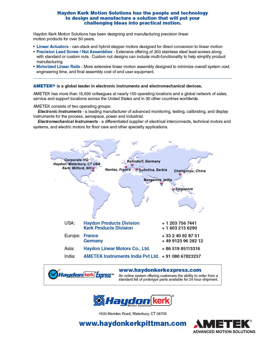
261
NTB Series Nut Assembies. Anti-Backlash Life. Without Kerkote TFE Coating inch / (cm) 100 to 125 million (250 to 315 million) With Kerkote TFE
 100 to 125 million (250 to 315 million) With Kerkote TFE") Screw and Nut Assemblies NTB Nut Series For higher load applications. The NTB Series anti-backlash assembly is designed for higher load applications than the ZBX or KHD series units. Using the specially
Screw and Nut Assemblies NTB Nut Series For higher load applications. The NTB Series anti-backlash assembly is designed for higher load applications than the ZBX or KHD series units. Using the specially
Anti-Backlash Life. Without Kerkote TFE Coating inch / (cm) 5 to 10 million (12 to 25 million) With Kerkote TFE
 5 to 10 million (12 to 25 million) With Kerkote TFE") Lead Screw and Nut ssemblies NTG Nut Series ompact size, zero backlash, minimal drag torque. The adjustable NTG Series offers a cost effective anti-backlash assembly for applications requiring precise
Lead Screw and Nut ssemblies NTG Nut Series ompact size, zero backlash, minimal drag torque. The adjustable NTG Series offers a cost effective anti-backlash assembly for applications requiring precise
Drive / Mounting. A = None
 HAYD: 203 756 7441 Motorized and Non-Motorized LRS Linear Rail Systems available with a Haydon Hybrid 43000 Series Size 17 single and double stack linear actuator stepper motor or as an non-motorized linear
Page numbers represent Printed Catalog pages
 Contact Information Contact Information HaydonKerk Motion Solutions TM www.haydonkerk.com North American HQ/Operations Haydon Switch and Instrument 10 Meriden Road Waterbury, CT 06705 Telephone: 203-756-7441
43M4 n n n n n n. 43L4 n n n n n n. E43M4 n n n n n n. Bipolar 5 VDC 12 VDC. 550 ma 1.3 A 21.9 Ω 3.8 Ω mh mh W Total.
 HAYD: 2 756 744 KERK: 6 2 629 4 Series: Double Stack Stepper Motor Linear Actuator Haydon 4 Series Double Stack hybrid linear actuators offer greater performance. Double Stack Captive Shaft The versatile
Identifying the Motorized RGS part number codes when ordering
 RGS04 Motorized with 28000 Series Size11 DS RGS04 Linear Rail for Hybird 28000 Series Size 11 Double Stacks and RGS04 for 43000 Series Size 17 Single and Double Stacks (See Page 4) RGS04 Linear Rail with
Creating Linear Motion One Step at a Time
 Creating Linear Motion One Step at a Time In classic mechanical engineering, linear systems are typically designed using conventional mechanical components to convert rotary into linear motion. Converting
LEAD SCREWS 101 A BASIC GUIDE TO IMPLEMENTING A LEAD SCREW ASSEMBLY FOR ANY DESIGN
 LEAD SCREWS 101 A BASIC GUIDE TO IMPLEMENTING A LEAD SCREW ASSEMBLY FOR ANY DESIGN Released by: Keith Knight Kerk Products Division Haydon Kerk Motion Solutions Lead Screws 101: A Basic Guide to Implementing
HaydonKerk Motion SolutionsTM Phone: International: Stepper Motor Linear Actuators
 HaydonKerk Motion SolutionsTM www.haydonkerk.com Phone: 800.243.2715 International: 203.756.7441 Stepper Motor Linear Actuators Stepper Motor Linear Actuators: Product Summary Hybrid Linear Actuators Series
SOME FACTORS THAT INFLUENCE THE PERFORMANCE OF
 SOME FACTORS THAT INFLUENCE THE PERFORMANCE OF Authored By: Robert Pulford Jr. and Engineering Team Members Haydon Kerk Motion Solutions There are various parameters to consider when selecting a Rotary
Screw Driven automation tables
 automation tables Precise multi-axis positioning systems play an integral part in today s semiconductor, computer peripheral, solar power, flat panel, life sciences, lab automation, biomedical and electronics
HSI Stepper Motor Theory
 HI tepper Motor Theory Motors convert electrical energy into mechanical energy. A stepper motor converts electrical pulses into specific rotational movements. The movement created by each pulse is precise
LEAD SCREW LINEAR ACTUATORS: WHEN TO APPLY EXTERNAL, NON-CAPTIVE AND CAPTIVE STEP MOTOR ACTUATORS
 LEAD SCREW LINEAR ACTUATORS: WHEN TO APPLY EXTERNAL, NON-CAPTIVE AND CAPTIVE STEP MOTOR ACTUATORS Authored By: Frank Morton and Engineering Team Members Haydon Kerk Motion Solutions A common way to generate
Creating Linear Motion One Step at a Time Precision Linear Motion Accomplished Easily and Economically
 Creating Linear Motion One Step at a Time Precision Linear Motion Accomplished Easily and Economically How Is a Linear Actuator Sized? Sizing a linear actuator is quite easy once you understand the basic
SUPERNUTS & LEAD SCREWS
 SUPERNUTS & LEAD SCREWS Overview......................................... 2-2 Advanced Anti-Backlash Supernuts.................. 2-4 Anti-Backlash Supernuts......................... 2-12 Flange Mount Supernuts..........................
HYBRID LINEAR ACTUATORS BASICS
 HYBRID LINEAR ACTUATORS BASICS TECHNICAL OVERVIEW Converting the rotary motion of a stepping motor into linear motion can be accomplished by several mechanical means, including rack and pinion, belts and
Leadscrews and Leadscrew Assemblies
 Leadscrews and Leadscrew Assemblies Section Contents Leadscrew and Assemblies Product Overview...Page 7 2 Selection Guide...Page 7 6 Leadscrew Sizes...Page 7 7 Leadscrew s...page 7 12 Modified and Custom
MultiCam 3000 Series CNC Router Feature and Specification Guide. Versatile, Feature-Rich Production Routing! The MultiCam. Ideal for Cutting: Wood
 MultiCam 3000 Series CNC Router Feature and Specification Guide Versatile, Feature-Rich Production Routing! The MultiCam 3000 Series CNC Routers are loaded with standard features normally associated with
Ultra Series: Crossed Roller Ultra Precision Stages
 Ultra Series: Crossed Roller Ultra Precision Stages Bayside Motion Group, has developed Ultra Positioning Stages for applications requiring the ultimate in accuracy. Available with a linear motor, ball
Repeatability. Prototyping. High Precision Lead Screws
 High Repeatability High accuracy Short Lead times Fast Prototyping High Precision Lead Screws Offering smooth, precise, cost effective positioning, lead screws are the ideal solution for your application.
NEW. Linear Ball Bushing Bearings and 60 Case Shafting. Profile Rail Linear Guides
 Linear Ball Bushing Bearings and 60 Case Shafting Thomson invented the ball bushing bearing over 60 years ago and has since been the recognized leader in this field. Our linear products provide low friction,
Heavy Duty Ball Screw Linear Actuators
 Heavy Duty Ball Screw Linear Actuators Thrust From 2,000 to 25,000 lbf Heavy Wall Steel Construction Longest Life Simultaneous High Thrust with High Speed Piston with Rugged Anti Rotation Feature Sealed
PRS Series Planetary Roller Screws. A Superior Alternative to Hydraulic or Pneumatic Motion Providing 15 times the Life of a Ballscrew
 PRS Series Planetary Roller Screws A Superior Alternative to Hydraulic or Pneumatic Motion Providing 15 times the Life of a Ballscrew Exlar Roller Screw Advantage Roller Screw Overview A roller screw is
A superior alternative to hydraulic or pneumatic motion providing 15 times the life of a ball screw. Planetary Roller Screws
 A superior alternative to hydraulic or pneumatic motion providing 15 times the life of a ball screw Planetary Roller Screws Exlar Your Linear Motion Experts Exlar Corporation is committed to providing
ML Series MINIATURE SCREW-DRIVEN LINEAR ACTUATOR LOW COST SOLUTION FOR PRECISION POSITIONING IN COMPACT SPACES!
 ML Series MINIATURE SCREW-DRIVEN LINEAR ACTUATOR Compact and easy to install, a low cost linear solution perfectly suited for the medical industry, life science and small scale automation applications.
Screw Driven automation tables
 Screw riven automation tables Precise multi-axis positioning systems play an integral part in today s semiconductor, computer peripheral, solar power, flat panel, life sciences, lab automation, biomedical
105000BT & BT/CT Series
 15BT & 16BT/CT Series Ball Bearing and Cross Roller Bearing Tables Designed for high accuracy and extremely smooth motion, 1 series tables are ideal for light to moderate duty cycle applications such as
stage from resolution accuracies is 400 peak) and the from an to outpu positioning (as shown N] continuous continuous needs
![stage from resolution accuracies is 400 peak) and the from an to outpu positioning (as shown N] continuous continuous needs](/thumbs/80/81553844.jpg "stage from resolution accuracies is 400 peak) and the from an to outpu positioning (as shown N] continuous continuous needs") Earthquake Simulation Using Single or Dual-Axis Linear Motion Stages With the goal of safer buildings and saving lives, scientists and engineers, through the simulation of many recent earthquakes, need
Earthquake Simulation Using Single or Dual-Axis Linear Motion Stages With the goal of safer buildings and saving lives, scientists and engineers, through the simulation of many recent earthquakes, need
The Latest Sensor Trends
 Sensing & Feedback Technologies The Latest Sensor Trends Agenda Miniature sensors open up new applications Alternatives to Fiber optics Pneumatic cylinder sensing: Dual systems, analog and lifetime warranties
Product Overview. Hansen Precision Electric Motors DC AC DC. Actuators. Stepper
 AC Hansen Precision Electric Motors Hansen s quality products are known around the world. These include: Synchron Motors, available with custom voltage, speed and power, durable brush motors, AC clock
Six keys to achieving better precision in linear motion control applications
 profile Drive & Control Six keys to achieving better precision in linear motion control applications Achieving precise linear motion Consider these factors when specifying linear motion systems: Equipped
Screw Driven automation tables
 automation tables Precise multi-axis positioning systems play an integral part in today s semiconductor, computer peripheral, solar power, flat panel, life sciences, lab automation, biomedical and electronics
acme & ball screws actuators linear motion drive components engineering ingenuity
 P R O D U C T O V E R V I E W acme & ball screws actuators linear motion drive components engineering ingenuity w w w. n o o k i n d u s t r i e s. c o m CC linear actuators CC Linear Actuators are ball
COMPARING SLOTTED vs. SLOTLESS BRUSHLESS DC MOTORS
 COMPARING SLOTTED vs. SLOTLESS Authored By: Engineering Team Members Pittman Motors Slotless brushless DC motors represent a unique and compelling subset of motors within the larger category of brushless
MANTECH ELECTRONICS. Stepper Motors. Basics on Stepper Motors I. STEPPER MOTOR SYSTEMS OVERVIEW 2. STEPPING MOTORS
 MANTECH ELECTRONICS Stepper Motors Basics on Stepper Motors I. STEPPER MOTOR SYSTEMS OVERVIEW 2. STEPPING MOTORS TYPES OF STEPPING MOTORS 1. VARIABLE RELUCTANCE 2. PERMANENT MAGNET 3. HYBRID MOTOR WINDINGS
TurboDisc Stepper Motors
 TurboDisc Stepper Motors P43 P532 P31 P11 P1 The TurboDisc provides exceptional dynamic performance unparalleled by any other stepper on the market. The unique thin disc magnet enables finer step resolutions
Courtesy of Steven Engineering, Inc - (800) PATENTED
 PATENTED") PRECISION RING DRIVE SYSTEMS Based on Nexen s innovative Roller Pinion technology, Nexen Ring Drive Systems come complete with a precision grade, high capacity bearing and drive mechanism in a rigid housing.
PRECISION RING DRIVE SYSTEMS Based on Nexen s innovative Roller Pinion technology, Nexen Ring Drive Systems come complete with a precision grade, high capacity bearing and drive mechanism in a rigid housing.
Precision Hybrid Stepper Linear Actuator Systems
 Precision Hybrid Stepper Linear Actuator Systems 2018 Distributed by Changzhou DINGS Electrical & Mechanical Co. Ltd. INTRODUCTION Motion Control Products Ltd., supplies quality leadscrew-style linear
ENGINEERED TO MOVE. DA Series Electric Roller Screw Actuators with Integrated Motors
 ENGINEERED TO MOVE DA Series Electric Roller Screw Actuators with Integrated Motors ENGINEERED TO MOVE DA Series Electromechanical Actuators (EMA) The DA Series electromechanical actuators (EMAs) are equipped
Glide Screw. Combines the Features of a Linear Bearing and Screw in One Compact Package
 Glide Combines the Features of a Linear Bearing and in One Compact Package Introduction What is a Glide? Part linear bearing, part lead screw; a combination of two favorites to create something better
Rotary Series Rotary Series: Direct Drive Precision Stages
 Rotary Series Rotary Series: Direct Drive Precision Stages Parker Bayside s Direct Drive Rotary Stages feature a robust construction and high performance in a compact package, providing smooth, near-frictionless
EMC-HD. C 01_2 Subheadline_15pt/7.2mm
 C Electromechanical 01_1 Headline_36pt/14.4mm Cylinder EMC-HD C 01_2 Subheadline_15pt/7.2mm 2 Elektromechanischer Zylinder EMC-HD Short product name Example: EMC 085 HD 1 System = ElectroMechanical Cylinder
FT Series Linear Actuators
 FT Series Linear Actuators Exlar FT Series force tube actuators use a planetary roller screw mounted inside a telescoping tube mechanism. The follower is attached to the moveable force tube, which then
Hybrid Stepper Motors
 DINGS Electrical & Mechanical Co., Ltd 3 Quality Performance Flexibility Price WHO IS DINGS? DINGS is a premier supplier of rotary and linear step motors. Based in the greater Shanghai, China area, we
SELECTING A BRUSH-COMMUTATED DC MOTOR
 SELECTING A BRUSH-COMMUTATED DC MOTOR BASIC PARAMETERS Permanent magnet direct current (DC) motors convert electrical energy into mechanical energy through the interaction of two magnetic fields. One field
Daedal Precision Gearheads
 Daedal Catalog 8085/US Introduction Quality, Performance, Reliability Parker are planetary gear reducers designed to excel in today s demanding servo motor applications. They offer a vast array of selectable
GSX SERIES. GSX Series Integrated Motor/Actuator
 Return to Table of Contents GSX SERIES INTEGRATED SERVO MOTOR AND ACTUATOR High quality screw for longer life Ideal hydraulic replacement Powerful and robust Compact size GSX Series 952.500.6200 www.exlar.com
Highest Precision: SPL Series
 Highest Precision: SPL Series GAM can. Just ask! If you don t see exactly what you need, let us know. We can modify the SPL Series gearboxes to meet your needs. Page 3 provides a list of commonly requested
Profi le rail guides LLR
 Profi le rail guides LLR Content The SKF brand now stands for more than ever before, and means more to you as a valued customer. While SKF maintains its leadership as the hallmark of quality bearings throughout
Contents. Page. 1. Product description. 2. The AXC line of linear axes. 3. AXLT line of linear tables. AXC and AXS product overview...
 SNR Industry Contents Page 3 1. Product description AXC and AXS product overview... 6-8 Dynamic load ratings of the linear motion systems... 9 Compact modules... 10-11 Linear tables... 12 Telescopic axes...
PC-Series Precision Linear Actuators. Optimize Your Machine and Save Energy With Reliable, High Performance, Compact Actuators
 PC-Series Precision Linear Actuators Optimize Your Machine and Save Energy With Reliable, High Performance, Compact Actuators Make the Change to Electric Enjoy superior performance and save time and energy
Mechanical Motion Solutions
 Mechanical Motion Solutions Mobile-Off-Highway Mechanical Motion Solutions New Name, Established Brands Thomson invented anti-friction linear technology over 60 years ago and has continued to lead the
TRANSLATION (OR LINEAR)
") 5) Load Bearing Mechanisms Load bearing mechanisms are the structural backbone of any linear / rotary motion system, and are a critical consideration. This section will introduce most of the more common
5) Load Bearing Mechanisms Load bearing mechanisms are the structural backbone of any linear / rotary motion system, and are a critical consideration. This section will introduce most of the more common
Sizes 50, 65, 80. Presence of internal channels for re-lubrication Large range of axis mounting accessories
 > Series 5E electromechanical axis C_Electrics > 207 Series 5E electromechanical axis New models Sizes 50, 65, 80 Multiposition system with transmission of the movement with toothed belt Suitable for high
Comparison Chart. extremely difficult. Finally, separated components can rarely be re-used.
 JAN 2014 Traditional Connections Why Go Keyless Keyed Bushing Systems Both QD and Taper-Lock bushing and weld-on hub systems are popular component mounting technologies. Yet both are ultimately keyed connections
The Straight Story on Linear Actuators
 The Straight Story on Linear Actuators Linear actuators can be powered by pneumatics, hydraulics, or electric motors. Which is best for your job? Let s find out. Linear actuation is employed everywhere,
TAKE IT TO THE NEXEN LEVEL
 TAKE IT TO THE NEXEN LEVEL INDUSTRIES SERVED Aerospace Automation Equipment Automotive Bottling CNC Machining Commercial Laundry Equipment Converting Conveying Food Processing Machine Tool Material Handling
PRECISION BELLOWS COUPLINGS
 PRECISION BELLOWS COUPLINGS Bellows couplings are used where precise rotation, high speeds, and dynamic motion must be transmitted. They exhibit zero backlash and a high level of torsional stiffness, offering
300 & 400 Series Positioning Tables
 300 & 400 Series Positioning Tables 300 Series Introduction L-2 400 Series Introduction L-3 Specifications L-5 300 Series Dimensions L-6 400 Series Dimensions L-7 300 Series Motor Couplings L-8 300 Series
 --554-6 www.microngearheads.com Mechanical and Electro-Mechanical Product Solutions by Danaher Motion Danaher Motion engineers, manufactures and markets a select combination of the world s top brands of
NLS4 SERIES LINEAR STAGE
 NLS4 SERIES LINEAR STAGE The NLS4 have been designed for a variety of applications in research and other industrial areas requiring precision positioning such as in semiconductor processing, fiber optics
Screw Driven automation tables
 automation tables Precise multi-axis positioning systems play an integral part in today s semiconductor, computer peripheral, solar power, flat panel, life sciences, lab automation, biomedical and electronics
Mechanical Motion. Control Components. and Subsystems. Understanding How Components Effect System Performance
 Mechanical Motion Control Components and Subsystems Understanding How Components Effect System Performance Mechanical Motion Control Components and Subsystems Overview: Bearings Linear Bearing Technologies
The gear boxes can be run at the same speeds as the actuator models. Do not exceed torque ratings.
 1. What is the lifting torque required? The lifting torque for a single actuator depends on the load, the worm gear ratio, type of screw (machine cut or ball screw) and the pitch of the lifting screw.
Miniature Positioners linear motor and screw driven stages
 linear motor and screw driven stages Miniaturization of fiber optics, photonics, electronics and biomedical processes has driven the need for smaller and more efficient positioners. Parker offers numerous
The headquarter ELMEQ A/S is located in Denmark, offering innovation, development and logistics all based on 20 years knowhow and experience.
 The headquarter ELMEQ A/S is located in Denmark, offering innovation, development and logistics all based on 20 years knowhow and experience. ELMEQ GmbH was founded in Germany 2011 and is working closely
Mini-MAG Positioning Products
 Mini-MAG Positioning Products Miniature Linear Stage The Mini-MAG (MMX) line of miniature linear stages blends the ultimate in performance, reliability, and value, delivering nearly twice the accuracy
Application Note : Comparative Motor Technologies
 Application Note : Comparative Motor Technologies Air Motor and Cylinders Air Actuators use compressed air to move a piston for linear motion or turn a turbine for rotary motion. Responsiveness, speed
Roller Screw Actuators: Benefits, Selection and Maintenance
 Roller Screw Actuators: Benefits, Selection and Maintenance Last Printed June 10, 2010; Author: Gary Shelton, Principal Design Engineer, Exlar Corp., Chanhassen, Minn. The choice of hydraulic/pneumatic
ATX165SL/SLE Series Mechanical-Bearing, Screw-Driven Linear Stage
 ATX165SL/SLE Series Mechanical-Bearing, Screw-Driven Linear Stage Travel lengths up to 250 mm with anti-creep crossed-roller bearings Optional center-mounted linear encoder for direct position feedback
Machine Tool Grade Ball Screw Linear Actuators
 Machine Tool Grade Ball crew Linear Actuators High Precision With Force To 15,000 LBf Rugged teel Construction Designed For High ystem tiffness Flexible Design To uit Any Motor Protected From Contamination
Linear Actuator Product Guide
 Unique Solutions for Unique Customers. Linear Actuator Product Guide Guiding you towards the right solution. A division of Cleveland Motion Controls An IMC Company More solutions from us means more options
Precision Hybrid Stepper Linear Actuator Systems
 Precision Hybrid Stepper Linear Actuator Systems 1 Quality Performance Flexibility Price The Koco Motion US LLC and DINGS Partnership Combining more than 5 years of experience in the Motion and Automation
Introducing Galil's New H-Bot Firmware
 March-16 Introducing Galil's New H-Bot Firmware There are many applications that require movement in planar space, or movement along two perpendicular axes. This two dimensional system can be fitted with
Ball Rail Systems RE / The Drive & Control Company
 Ball Rail Systems RE 82 202/2002-12 The Drive & Control Company Rexroth Linear Motion Technology Ball Rail Systems Roller Rail Systems Standard Ball Rail Systems Super Ball Rail Systems Ball Rail Systems
LINEAR MOTION CONTROL
 LINEAR MOTION CONTROL Technical Data Sheet Rod Locks RLSS Series Nexen s new generation of linear holding/locking devices take rod locking technology to the next level. With superior performance, these
Our Mission. Our Brand Promise
 M O D U L A R A C T U A T O R S P R O D U C T w w w. n o o k i n d u s t r i e s. c o m G U I D E Our Mission Our mission is to be an innovative and responsive organization. Nook Industries knowledge and
C-SERIES S-SERIES. Metric Machine Screw Jacks EMA LINEAR ACTUATORS
 C-SERIES S-SERIES Metric Machine Screw Jacks EMA LINEAR ACTUATORS Power Jacks has a proud engineering heritage dating from the earliest years of the 20th Century. A heritage that is about excellence: about
Rotary Tables. Z Theta system
 Rotary Tables High force Air bearings Roller bearings XY tables Z Theta system Cartesian systems Linear stepping motors and systems Linear brushless motors and systems Linear measurement systems Semiconductor/Electronics
X-LSM-E Series Datasheet
 Simplifying Motion Control X-LSM-E Series Datasheet * 25, 50, 100, 150, 200 mm travel * 10 kg load capacity * Up to speed and up to 55 N thrust * Built-in controller; daisy-chains with other Zaber products
FTP Series HIGH FORCE ELECTRIC PRESS ACTUATOR
 FTP Series HIGH FORCE ELECTRIC PRESS ACTUATOR Ideal hydraulic press replacement Industry-leading power density Rugged and reliable Flexible and precise 952.500.6200 www.exlar.com 75 FTP Series High Force
Selecting the Optimum Motion Control Solution for the Application By Festo Corporation
 Selecting the Optimum Motion Control Solution for the Application By Festo Corporation The successful machine builder develops products that offer superior price, performance, reliability, and the ability
Application Notes. Calculating Mechanical Power Requirements. P rot = T x W
 Application Notes Motor Calculations Calculating Mechanical Power Requirements Torque - Speed Curves Numerical Calculation Sample Calculation Thermal Calculations Motor Data Sheet Analysis Search Site
Linear Motion. Optimized.
 Thomson - Linear Motion. Optimized. Linear Motion. Optimized. Often the ideal design solution is not about finding the fastest, sturdiest, most accurate or even the least expensive option. Rather, the
VERLON No Swell Wear Rings
 VERLON No Swell Wear Rings Ultra precision +.001 tolerance on cross section NO SWELL - Lowest friction Strength to 40,000 PSI Large range of widths, cross sections and diameters - metric too Features &
Ledex Rotary Solenoids
 Ledex Rotary Solenoids Maximum Duty Cycle 00% 50% 5% 0% 5% Maximum ON Time (sec) 00 36 8.8 when pulsed continuously Maximum ON Time (sec) 6 44 9 3. for single pulse Watts (@ 0 C) 0 0 40 00 00 Ampere Turns
QMOT Motor QSH4218 Manual 42mm QMOT motor family
 QMOT Motor QSH4218 Manual 42mm QMOT motor family Trinamic Motion Control GmbH & Co. KG Sternstraße 67 D 20357 Hamburg, Germany Phone +49-40-51 48 06 0 FAX: +49-40-51 48 06 60 http://www.trinamic.com INFO@TRINAMIC.COM
Candy Coup-Link OVER YEARS OF INNOVATION
 Candy Coup-Link Zero-backlash, flexible-shaft couplings High torque, excellent response Accommodates misalignment and shaft endplay Aluminum and stainless steel options Inch and metric bores available
Motion Solutions for Clean Energy Applications. Linear Motion. Optimized.
 Motion Solutions for Clean Energy Applications Linear Motion. Optimized. Linear Motion. Optimized. Solar Energy High energy prices have fueled double-digit growth in the solar energy industry with continued
HARMONIC GEARHEAD. Features & Benefits Specifications... 53
 HARMOIC GEARHEAD exen s revolutionary (HG) is the perfect combination of size and precision. Use the integrated with exen s RPS Pinion (HGP) to create a true backlash-free solution from the motor to the
Sizes 50, 65, 80. Accessories for cables fixing. Presence of internal channels for re-lubrication Large range of axis mounting accessories
 > Series 5E electromechanical axis C_Electrics > 206 Series 5E electromechanical axis New Sizes 50, 65, 80 Multiposition system with transmission of the movement with toothed belt Suitable for high dynamics
PRODUCTS OVERVIEW. Linear Motion in its Simplest Form
 Linear Motion in its Simplest Form Simplicity of Design - IntelLiDrives TM produce direct linear motion, eliminating stretching belts, slipping pulleys, hysteresis and wear of the leadscrews. Cost Effective
New! Parallel Actuators. In-line Actuators. Controls. Contents. Programming
 Danaher Linear has long been the leader in ball bearing screws and linear actuators. This new line of Electrak programmable linear actuators offers an expanded range of performance in life, load carrying
Profile rail guides LLT
 Profile rail guides LLT Contents The SKF brand now stands for more than ever before, and means more to you as a valued customer. While SKF maintains its leadership as the hallmark of quality bearings throughout
Precision Technology Overview
 Precision Technology Overview 2 Precision Automation Applications and industries integrating precision motion control have requirements that exceed most motion product capabilities - levels of accuracy,
zt10 PROmech Series Miniature Linear Positioners Catalog 8094/USA Daedal
 zt10 PROmech Series Miniature Linear Positioners Catalog 8094/USA Daedal PROmech LP28 Miniature Linear Positioner PROmech LP28 Miniature Linear Positioner Features: Miniature Profile Optimal length to
GRA GRV SERIES GRA PARALLEL GRIPPERS SERIES GRV ANGULAR GRIPPERS. Compact Precision Grippers Ideal for a Wide Range of Applications
 GRA GRV SERIES GRA PARALLEL GRIPPERS SERIES GRV ANGULAR GRIPPERS Compact Precision Grippers Ideal for a Wide Range of Applications Series GRA Parallel Series GRV Angular GRAV0 ORDERING DATA: SERIES GRA
Plastic bearings that revolve around your needs.
 NON-CORROSIVE n NON-MAGNETIC n LIGHTWEIGHT Plastic bearings that revolve around your needs. FROM MAGNUS MOBILITY SYSTEMS ISO 9001-2008 Certified Plastic bearings that revolve around your needs We go to
Ball Screws Inch Series
 Ball Screws Inch Series BALL SCREWS Table of Contents Description Page Product Overview................................ 38 Precision Rolled Ball Screws Inch Series......... 42 Visual Product Reference
Precision on the highest level
 6 - line Precision on the highest level The series is the standard Neugart inline high precision planetary gearhead for applications with very high precision requirements. Whether high torque density,