Precision Hybrid Stepper Linear Actuator Systems
|
|
|
- Camilla Wilkinson
- 6 years ago
- Views:
Transcription


1 Precision Hybrid Stepper Linear Actuator Systems 1


2 Quality Performance Flexibility Price The Koco Motion US LLC and DINGS Partnership Combining more than 5 years of experience in the Motion and Automation Industries, the Koco Motion US LLC and DINGS USA partnership brings together manufacturing facilities located in the United States and China. These facilities provide a supply chain that allows us to deliver quality, cost effective product solutions to our North American OEM customers in an efficient, time-sensitive market environment. Our ability to create innovative custom solutions allows us the flexibility to meet our customers diverse applications. Our lead screws are precision rolled in our California manufacturing facility to our customers specifications. Final assembly of our linear actuator assemblies are then fully tested and inspected before shipping directly to our OEM customers. Our dedicated California Quick-Turn prototyping team allows for fast response for OEM customers needing to shorten the time to concept approval and time to market. Our patented ServoTrack TM Drivers and Controllers are designed in California and assembled and tested in our California manufacturing facility. See pages 6 8. ISO Certification 2 San José, California Manufacturing Facility Hybrid Stepper Motor Linear Actuator Systems TECHNICAL SUPPORT:


3 TABLE OF CONTENTS Warranty 4 ServoTrack TM Technology Driver/Controller Solutions 6 Hybrid Stepper Linear Actuator Overview 1 Technology Overview of Linear Systems 11 Product Selection Considerations 17 Basic Specifications of Linear Systems 2 Product Selection Guide 21 Encoder Options 22 Lead Screw Code Schedule 24 NEMA 8 2 mm Hybrid Stepper Linear Actuators 25 NEMA mm Hybrid Stepper Linear Actuators 33 NEMA mm Hybrid Stepper Linear Actuators 41 NEMA mm Hybrid Stepper Linear Actuators 54 NEMA mm Hybrid Stepper Linear Actuators 67 NEMA mm Hybrid Stepper Linear Actuators 8 Glossary 85 3


4 Quality Performance Flexibility Price WARRANTY Twenty Four Month Limited Warranty Seller warrants its products delivered hereunder to conform to stated specifications and to be free from defects in materials and workmanship. This warranty shall not apply to any product which shall have been improperly installed or subjected to misuse or neglect or which has been repaired or altered except by seller s accredited representative, nor to any product which has been subjected to accident. DISCLAIMER The information in this catalog has been carefully checked and is believed to be accurate; however, no responsibility is assumed for inaccuracies. Koco Motion US LLC / DINGS reserves the right to make changes without further notice to any products herein to improve reliability, function, or design. Koco Motion US LLC / DINGS does not recommend the use of its products in life support or aircraft applications wherein a failure or malfunction of the product may directly threaten life or injury. CUSTOMS ARE STANDARD FOR US... 4 Custom cabling, connector, and screw end machining Custom cabling, connector, and sensors Hybrid Stepper Motor Linear Actuator Systems TECHNICAL SUPPORT:


5 Rolled and Assembled in California Custom cabling and connector Custom anti-backlash nut and connector Cable bundling Kitted assemblies 5 CUSTOMS ARE STANDARD FOR US...
6 Quality Performance Flexibility Price Drive and Controller Solutions ServoTrack TM Tomorrow s Technology for Today s Application TM Why step motors were a great invention... Step motors, as a result of the way they are constructed, are inherently lower cost than servo motors. Step motors do not require tuning, allow for a greater inertia mismatch, and have very high torque density. This torque is 1% available immediately upon startup, which can be very advantageous when doing short quick moves or when coupled to high inertia loads. Because step motors are synchronous motors with a high pole count, they are able to run smoothly at extremely slow speeds with little torque ripple. Step motor systems have unique characteristics, such as smother motion, stiffness at stand-still, no tuning, and low cost. Popular for decades, these systems will continue to be a popular choice among design engineers. 1% Typical stepper speed-torque curve sized with ServoTrack Design smart with ServoTrack TM Key benefits: Solve applications previously considered too demanding for stepper systems. Reduce system cost with an enhanced stepper based system. Do you need torque control in your stepper system? Does your system stall due to transient loads or friction? Eliminate unintentional stalling or loss of synchronization. Increase throughput efficiency. Reduce motor heating and energy costs with variable current control. Optimize the torque utilization of your motor. Greater compliance with inertial mismatch. 6 5% sized without ServoTrack step motor speed ServoTrack TM control is hardware based for real-time response. It continually monitors the relationship between the rotor and stator at nanosecond intervals, and will not allow that relationship to exceed the point where motor synchronization is lost. Although both servo and step motors are permanent magnet synchronous motors, there are differences. Brushless servo motors typically have 2 to 8 magnetic poles on the rotor, whereas the 1.8 degree step motor has 5 poles. It can be thought of as electromagnetically geared down compared to servo motors and thus has a higher torque density. torque However, there are some disadvantages with today s step motor control technology. The most critical drawback is the loss of synchronization and torque if a large load exceeds the motor s capacity and its ability to resynchronize once the load is reduced to a level within the motor s capability. Step motor also tend to run hot because of the use of full phase current independent of load. Historically, these disadvantages may have influenced the decision to choose higher cost servo technology over traditional step motor technology. Now with the introduction of ServoTrack TM, unintentional stalling due to transient loads, or excess friction, is eliminated and torque control becomes an integral function of your stepper system. Hybrid Stepper Motor Linear Actuator Systems TECHNICAL SUPPORT:


7 Drive and Controller Solutions ServoTrack TM Tomorrow s Technology for Today s Application TM ServoTrack TM the applications are endless... Whether you are designing a new system or wanting to improve the performance of an existing one, ServoTrack TM will make your application more robust and dependable, and keep your costs low. Dramatically simplify and expand the ways in which you apply step motor technology to solve motion control applications: 1. Allow full use of the motor s torque with minimal de-rating of the speed/torque curve. 2. Never lose functional control of the motor. 3. Lower the cost of your servo axis Minimize the impact of system resonance. 5. Allow for higher inertia mismatch when sizing your system. 6. Torque control for clamping, winding/unwinding, and tension control. 7. With variable current control, minimize motor heating and improve efficiency. 8. Prevent transient load stalling on smart conveyor systems. 9. No controller required when applied in velocity mode with built-in oscillator. 1. Simple set-up with no tuning required. 11. ServoTrack TM works through hardware, not PID software, greatly improving response time and eliminating the need for a high resolution encoder. 12. Reduce servo system complexity.

8 Quality Performance Flexibility Price ST486 Microstepping Stand Alone Driver/Controller Standard Specifications INPUT VOLTAGE (+V) Range +12 to +48 VDC OUTPUT CURRENT RMS (Max) Peak (Per Phase) 6 Amps 8 Amps ISOLATED INPUT Step Clock, Direction and Enable Voltage Range +5 to +24 VDC Sourcing or Sinking ServoTrack TM in in 3.5 in Other Available Driver/Controller Products 1. Smaller integrated Form Factor Driver that can be mounted on the rear motor end bell of linear or rotary motor. 2. Smaller integrated Form Factor Driver/Programmable Controller that can be mounted on the rear motor end bell of linear or rotary motor. Hybrid Stepper Motor Linear Actuator Systems TECHNICAL SUPPORT:


 9 FOR US, CUSTOMS")


9 Custom Stepper Motors and Lead Screw Assemblies IMMEDIATE AVAILABILITY OF PROTOTYPING UNITS... CALL US AT TO PLACE AN ORDER. 8:AM 5:PM PACIFIC STANDARD TIME (PST) 9 FOR US, CUSTOMS ARE STANDARD! Wide variety of prototyping product readily available in our San José, California facility High flexibility and capability in designing and manufacturing custom products to your OEM specifications Very competitive pricing
10 Quality Performance Flexibility Price HYBRID STEPPER LINEAR ACTUATOR OVERVIEW Nema Sizes Available Versions Motor Length & Available Currents (Voltage) Max Thrust Recommended Load Limit* Screw Lead Range 1.8 Degree NEMA 8 Stepper Single Stack (27mm):.5A (2.5V) Double Stack (38mm):.5A (4.4V) 78N (17.5lbs) 84N (18.9lbs) 43N (9.7lbs).12" -.315" (.3mm - 8.mm) 1.8 Degree NEMA 11 Stepper Single Stack (34mm):.5A (4.5V), 1.A (2.2V) Double Stack (45mm):.95A (3.9V) 23N (51lbs) 34N (76lbs) 15N (34lbs).25" -.4" (.635mm mm) 1.8 Degree NEMA 14 Stepper Single Stack (34mm):.5A (6.6V), 1.A (3.3V), 1.5A (2.2V) Double Stack (46mm):.5A (12.V), 1.A (6.V), 1.5A (4.V) 45N (1lbs) 61N (135lbs) 23N (52lbs).24" -.5" (.696mm mm) 1.8 Degree NEMA 17 Stepper Single Stack (34mm):.5A (7.2V), 1.A (3.6V), 1.5A (2.4V) Double Stack (48mm):.5A (11.V), 1.2A (4.5V), 2.5A (2.2V) 71N (16lbs) 9N (2lbs) 23N (52lbs).24" -.5" (.696mm mm) 1.8 Degree NEMA 23 Stepper Single Stack (45mm): 1.A (6.4V), 2.A (3.2V), 3.A (2.1V) Double Stack (65mm): 1.A (1.8V), 2.5A (4.2V), 4.A (2.4V) 14N (315lbs) 18N (45lbs) 92N (21lbs).25" - 1." (.635mm mm) 1.8 Degree NEMA 34 Stepper Single Stack (76mm): 1.3A (12.V), 3.A (5.1V), 5.5A (2.85V) 24N (54lbs) 216N (485lbs).1" - 1." (2.54mm mm) *These are nominal load limits. Operating above these limits may decrease useful life of the system. 1 Please see pages 6 8 for a review of our patented ServoTrack TM Driver/Controller solutions for all our linear and rotary stepper systems. IMMEDIATE AVAILABILITY OF PROTOTYPING UNITS... CALL US AT TO PLACE AN ORDER. 8:AM 5:PM PACIFIC STANDARD TIME (PST) FOR US, CUSTOMS ARE STANDARD! Hybrid Stepper Motor Linear Actuator Systems TECHNICAL SUPPORT:
11 TECHNOLOGY OVERVIEW One of the most common methods of moving a load from point A to point B is through linear translation of a motor by a mechanical lead screw and nut. This section is here to assist and refresh your understanding of the basic principles of lead screw technology prior to selecting the system that is best for your application. Please also reference the Glossary (page 85 of the catalog) to support your understanding. Some basic design considerations are as follows: 1. What is the load of your system? 2. What is the required speed to move from point A to point B? 3. What is the distance to be travelled? 4. What is the required time to move from point A to point B? 5. What accuracy does your application require? 6. What repeatability does your application require? 7. Horizontal vs vertical orientation? An Explanation of the Basics For a more detailed primer of Stepper Linear Actuator technology, please visit our website and download our Linear Actuator White Paper at. LEADS VS PITCH Pitch is the axial distance between threads. Pitch is equal to lead in a single start screw. There may be more than one thread strand on a single screw. These are called starts. Multiple start lead screws are usually more stable and efficient at power transmission. Lead is the axial distance the nut advances on one revolution of the screw. Throughout this catalog, lead will be the term used for specifying a screw as it is the linear distance travelled for one revolution of the screw. The larger the lead, the more linear distance travelled per one revolution of the screw. LOAD Typically quantified as either lbs OR kg to move or pounds force (lbsf) or kgf for thrust. 11 VELOCITY (V) Typically quantified as either inches/second (mm/sec) required for your application. DISTANCE Typically quantified as either inches or mm, is the required move distance. TIME (t) Typically quantified in seconds. Time period required for a given distance defines the velocity, acceleration (A), and deceleration needed to reach commanded position.
12 Quality Performance Flexibility Price HORIZONTAL OR VERTICAL APPLICATION Vertical orientation applications add the potential problem of backdriving when power to the motor is off and without an installed brake. Vertical applications also have an additional gravity factor that must be part of the load/force calculation. ACCURACY OF SCREW Specified as a measurement over a given length of the screw. For example:.6 in per inch. Lead accuracy is the difference between the actual distance travelled versus the theoretical distance travelled based on the lead. For example: A screw with a.5 inch lead and.4 inch per foot lead accuracy rotated 24 times theoretically moves the nut 12 inches. However, with a lead accuracy of.4 inch per foot, actual travel could be from to 12.4 inches. TOTAL INDICATED RUNOUT The amount of wobble around the centerline of the screw. REPEATABILITY Most motion applications put the most significance on the repeatability (vs accuracy of screw) of a system to reach the same commanded position over and over again. For example: A repeatability of ±.5 inch means that after repeated commands to reach the same target position, the linear error will be no more than ±.5 inch. TENSION OR COMPRESSION LOADING A load that tends to stretch the screw is called a tension load. A load that tends to squeeze or compress the screw is called a compression load. Depending on the size of the load, designing the screw in tension utilizes the axial strength of the screw versus column loading. 12 Compression Loading Tension Loading RADIAL LOAD A load perpendicular to the screw. This is not recommended unless additional mechanical support such as a linear guide is used. Radial Loading (Avoid or Minimize) Hybrid Stepper Motor Linear Actuator Systems TECHNICAL SUPPORT:
13 Axial Center Loading (best) AXIAL LOAD A load that exerted at the center line of the lead screw. STATIC LOAD The maximum thrust load, including shock load, that should be applied to a non-moving screw. DYNAMIC LOAD The maximum recommended thrust load which should be applied to the screw while in motion. BACKDRIVING Backdriving is the result of the load pushing axially on the screw or nut to create rotary motion. Generally, a nut with an efficiency greater than 5% will have a tendency to backdrive. Selecting a lead screw with an efficiency below 35% may prevent backdriving. The smaller the lead, the less chance for backdriving or free wheeling. Vertical application are more prone to backdriving due to gravity. TORQUE The required motor torque to drive just the lead screw assembly is the total of: 1. Inertial Torque 2. Drag Torque (friction of the nut and screw in motion) 3. Torque to move load LUBRICATION The nut material contains a self-lubricating material that eliminates the need for adding a lubricant to the system. The Teflon coated screw option also lowers friction and extends life of the system. 13 END MACHINING OF THE SCREW Standard metric or English options are available. Custom end machining specifications are also available on request. Threaded end Smooth end None Please refer to individual NEMA Size section for standard options. Custom machined ends are also available. Example: UNC end: #8-32 UNC thread Metric end: M4 x.7 mm thread Example: Ø.1967 ±.1 Ø 5 mm ±.25
14 Quality Performance Flexibility Price FIXITY The performance (speed and efficiency) of the screw system is affected by how the screw ends are attached and supported. Type of End Fixity Relative Rigidity Critical Speed Factor Critical Load Factor Less Rigid Rigid More Rigid Most Rigid COLUMN STRENGTH When a screw is loaded in compression, its limit of elastic stability can be exceeded and the screw will fail due to bending or buckling. CRITICAL SPEED Critical speed is the rotational speed of the screw at which the first harmonic of resonance is reached due to deflection of the screw. A system will vibrate and become unstable at these speeds. Several variables affect how quickly the system will reach critical speed: 1. The lead of the screw 2. The rotational speed 3. End fixity 4. Thrust load 5. Diameter of the screw 6. Tension or compression loading For example, the following chart shows that for a screw with a 3/4 inch diameter and 7 inch length, the threshold for critical speed is 7 RPM. Hybrid Stepper Motor Linear Actuator Systems TECHNICAL SUPPORT:
15 CRITICAL ROTATION SPEED (RPM) VS. UNSUPPORTED SCREW LENGTH FOR VARIOUS SCREW DIAMETERS (INCH) BACKLASH Backlash is the relative axial movement between a screw and nut at standstill. It is normal for backlash to increase with wear over time. Backlash compensation or correction can be accomplished through the application of an anti-backlash nut. Backlash is usually only a concern with bi-directional positioning. Standard Nut Lead Screw 15 Tension Anti-Backlash Nut Koco Motion s Compression Anti-Backlash Nut Lead Screw Lead Screw


 NEMA SIZE 23 ANTI-BACKLASH")
16 Quality Performance Flexibility Price Anti-Backlash Nuts Available upon Request NEMA SIZE 8 AND NEMA SIZE 11 ANTI-BACKLASH NUT NEMA SIZE 14 AND NEMA SIZE 17 ANTI-BACKLASH NUT 16 IMMEDIATE AVAILABILITY OF PROTOTYPING UNITS... CALL US AT TO PLACE AN ORDER. 8:AM 5:PM PACIFIC STANDARD TIME (PST) NEMA SIZE 23 ANTI-BACKLASH NUT Hybrid Stepper Motor Linear Actuator Systems TECHNICAL SUPPORT:


17 LINEAR MOTION SYSTEM TYPES A. Non-Captive B. External Linear C. Captive A. B. C. WHY CHOOSE ONE FORM FACTOR OVER THE OTHER? 1. What is the best mechanical fit for your application? 2. How do you plan to attach the screw? 3. Is rotation of the screw acceptable? 4. Does your application require an encoder or brake? 5. What is the stroke of your application? 17 WHAT ENVIRONMENTAL CONSIDERATIONS DO YOU HAVE? Koco Motion / DINGS linear motion systems are designed to operate in dry and non-corrosive environments. Standard products do not have an IP rating. Operating non-ip rated linear systems in dirty or corrosive environments will significantly reduce product life. TEMPERATURE Very high or low temperatures may cause significant changes in nut fit or drag force. MAXIMUM DYNAMIC LOAD Each NEMA frame size motor has a mechanical load maximum that should not be exceeded. For more information, see Speed/Force curves for the individual frame sizes. MOTOR SELECTION In order to select the right motor/lead screw combination with the lead screw, several factors should be considered: 1. How much force is required? 2. What is the desired step angle? 3. Detent or holding force requirements? 4. Physical size restrictions? 5. What type of driver (amplifier) are you using?
18 Quality Performance Flexibility Price Product Selection Guide To reduce complexity and cost of a design, it is important to accurately size a motor/lead screw combination. Below are a few simple steps in selecting the necessary components for a given application. Step 1 Choosing a motor NEMA size (Force requirements) Here is a general overview of the output thrust vs. NEMA size: NEMA Sizes Max Thrust Recommended Load Limit NEMA 8 78N 43N (17.5lbs) (9.7lbs) NEMA 11 NEMA 14 NEMA 17 NEMA 23 NEMA 34 23N (51lbs) 45N (1lbs) 71N (16lbs) 14N (315lbs) 24N (54lbs) 15N (34lbs) 23N (52lbs) 23N (52lbs) 92N (21lbs) 216N (485lbs) 18 As the NEMA size of the motor is increased, the output thrust of the actuator is consequently increased. Step 2 Choosing a screw lead (Force and Speed requirements) After estimating the required thrust and choosing a NEMA size that may fit your application, the speed and acceleration of the load must be considered and evaluated to choose an appropriate screw lead. Due to the nature of lead screws, the output speed and output thrust achievable by a motor/lead screw combination are two inversely proportional variables (i.e., increasing the required thrust will lower the achievable speed for a motor/lead screw combination). Therefore, the maximum output force of a system is lowered for applications that require higher speeds. For complete motor/lead screw selection data, please refer to the speed/thrust curves for each NEMA size. PLEASE CALL US AT :AM 5:PM PACIFIC STANDARD TIME (PST) FOR US, CUSTOMS ARE STANDARD! Hybrid Stepper Motor Linear Actuator Systems TECHNICAL SUPPORT:
19 Product Selection Guide (continued) Although these two steps provide a solid foundation in motor/lead screw selection, other variables must also be considered: Duty Cycle Desired Life of a System Environmental Considerations Positional Repeatability Acceptable Backlash Acceleration/Deceleration Requirements Driver Specifications Vertical or Horizontal Orientation Because of the numerous variables involved in motor selection, it is highly recommended for users to proceed with physical testing to accurately determine the motor/lead screw combination required for a given application. NOTE: Although this section aims to provide a rough guide to selecting a motor/lead screw combination that best fits an application, we recommend contacting our application engineering staff for further assistance with the motor selection process. Trapezoidal Move vs. Triangular Move Profile There are generally two widely used movement profiles. Depending on the required travel time and distance, different movement profiles can be used. The area under the curves below is the minimum stroke of the linear actuator, its required travel. Speed Speed 19 Desired Speed Desired Speed Minimum Stroke Time Minimum Stroke Time Required Time Required Time Required TRAPEZOIDAL MOVE TRIANGULAR MOVE
20 Quality Performance Flexibility Price Basic Specifications for Koco Motion / DINGS Linear Systems LEAD SCREW MATERIAL Unless otherwise noted, all reference to lead screws in this catalog have the following characteristics: Lead Screw Material Screw Coating 33 Stainless precision cold rolled steel Teflon coating is optional Lead screws are manufactured via precision rolling process at our San José, California facility. Standard Screw Accuracy.6 in /inch (Lead accuracy) Screw Repeatability System Repeatability (Motor and Screw) Screw Straightness Screw Efficiency Operating Temperature Screw Backlash 2 System Backlash Nut Material Wear life of Screw and Nut ±.6 inch Nominally the same as screw repeatability; motor variance adds ±6 micro steps..3 inch/foot, measured as Total Indicated Runout (TIR) All screws are carefully checked for straightness before shipment. From 35% to 85% dependent on lead. Also depends on the usage of an anti-backlash nut with screw. The larger the lead, the higher the efficiency of the screw. 1 C to +5 C (14 F to 122 F) Depends on lead (nominally ±.5 in) Includes screw, motor, and attached mechanics This will be the sum of all the backlash in your motion axis. Polyacetal with lubricating additive; Standard is a free-wheeling nut. [Anti-backlash version is available] Depends on load, speed, duty cycle, and environmental factors [typically > 5 million cycles] NOTE: Koco Motion / DINGS linear systems are manufactured from high quality materials. Because of the variable effects of friction, lubrication, and cleanliness, an exact life cannot be predicted for a given application. CUSTOM PRODUCT SPECIFICATIONS ARE WELCOME CONTACT A KOCO MOTION APPLICATION ENGINEER AT :AM 5:PM PACIFIC STANDARD TIME (PST) Hybrid Stepper Motor Linear Actuator Systems TECHNICAL SUPPORT:
21 Product Selection System P 17 N K T M S EK2FI Drive Option: D = Drive Only P = Programmable Controller and Drive 2 NEMA Size: NEMA CODE MOTOR SIZE (mm) 3 Lead Screw Shaft Style: N = Non-Captive Linear E = External Linear C = Captive Linear 4 Step Angle 2 = 2 Phase with = 2 Phase with.9 3 = 3 Phase with = 5 Phase with.72 5 Motor Length/Stack 1 = Single Stack 2 = Double Stack 6 Rated Current/Phase XX = X.X (A)/Phase 7 Lead Screw Code A Z, AA, AF Number of Lead Wires 4 = Qty 4 Flying Leads 6 = Qty 6 Flying Leads 8 = Qty 8 Flying Leads 9 Lead Screw Length/Stroke XXX = XXX mm Lead Length (For External Linear/Non-Captive Linear) XXX = X.XX inch Stroke (For Captive Linear) 1 Lead Screw Surface T = Teflon Coating S = Standard (No Teflon Coating) 11 End Machining M = Metric U = UNC S = Smooth N = None 12 Nut Style S = Standard Flange Nut A = Anti-Backlash Nut 13 Encoder Option EKXX = Encoder (XX = Encoder Code) ERX = Encoder Ready (X = Encoder Version) N = No Encoder nor Encoder Ready 21 EXAMPLE Part Number Description P17N2115K4-11.6TMSEK2FI Programmable Controller and Drive NEMA 17 Non-Captive Linear Actuator 2 Phase with 1.8 Degree Step Angle Single Stack 1.5 A/Phase K Lead (.1 /2.54 mm) 4 Flying Leads Screw Length: 11.6 mm Teflon Coated Screw Metric End Machining Standard Nut EK2 Encoder with Differential Output, 5 Lines, with Index
22 Quality Performance Flexibility Price Encoder Options EK1 ENCODER SINGLE ENDED OUTPUT EK1 ENCODER DIFFERENTIAL OUTPUT EK2 ENCODER SINGLE ENDED OUTPUT EK2 ENCODER DIFFERENTIAL OUTPUT 22 Encoder Options EK1 Line Count Single Ended Differential A B C D E F G H I J EK2 Line Count Single Ended Differential A B C D E F G H I Custom Encoder or Custom Line Count: EC For Encoder Ready Motors: ER1/ER2 For EK2 with Index: Add I as a suffix. For Example, for EK2, 512 line count, with Differential, and Index: EK2GI Please refer to our website for complete encoder specifications: Hybrid Stepper Motor Linear Actuator Systems TECHNICAL SUPPORT:
23 Number of Lead Wires Step motors typically come with 4, 6, or 8 wire leads. With bipolar drivers, there are 4 connections to a motor. Wiring up a 4 lead motor is straightforward. When using motors with 8 leads, the coils can either be connected in series or parallel. LEAD WIRE CONFIGURATION Red Red/Wht M Blue Red Yellow Green M Grn Grn/Wht 2 Phases 4 Lead Wires Brown Black Orange White 2 Phases 8 Lead Wires A six wire lead with two phases A six wire stepper motor with windings in series Red White Blue M A1 B1 23 A2 B2 Black Yellow Green 2 Phases 6 Lead Wires An eight wire stepper motor with windings in series An eight wire stepper motor with windings in parallel A1 B1 A1 B1 A2 B2 A2 B2
24 Quality Performance Flexibility Price Motor Lead Screw Code Schedule 24 Lead Code AF AA A B D F G H J K L M P Q R S T U V W X Y Z 1.8 Degree Motor Travel per Step mm (inch).15 (.6 ).348 (.12 ).3175 (.125 ).696 (.24 ).635 (.25 ) (.3125 ).1 (.395 ).1541 (.415 ) (.48 ).127 (.5 ) (.625 ).2 (.79 ).2129 (.835 ) (.96 ).254 (.1 ).3175 (.125 ).4 (.1575 ) (.1665 ) (.1875 ) (.192 ).58 (.2 ).635 (.25 ).127 (.5 ) Size 8 Size 11 Size 14 Size 17 Size 23 Size 34 Screw Dia. mm (inch) (.138 ).3 (.12 ).696 (.24 ) (.48 ) 2. (.79 ) 4. (.158 ) 8. (.315 ) (.188 ).635 (.25 ) 1.27 (.5 ) 2.54 (.1 ) 5.8 (.2 ) 1.16 (.4 ) 6.35 (.25 ) 6.35 (.25 ) Screw Lead mm (inch).696 (.24 ) (.48 ) 1.27 (.5 ) (.625 ) (.96 ) 2.54 (.1 ) (.192 ) 6.35 (.25 ) (.33 ) (.384 ) 12.7 (.5 ).696 (.24 ) (.48 ) 1.27 (.5 ) (.625 ) (.96 ) 2.54 (.1 ) (.192 ) 6.35 (.25 ) (.33 ) (.384 ) 12.7 (.5 ) (.375 ).635 (.25 ) 1.27 (.5 ) (.625 ) (.83 ) 2.54 (.1 ) (.125 ) (.167 ) 5.8 (.2 ) 6.35 (.25 ) (.375 ) (.384 ) 12.7 (.5 ) 25.4 (1. ) (.625 ) 2.54 (.1 ) (.125 ) 5.8 (.2 ) 6.35 (.25 ) 12.7 (.5 ) 25.4 (1. ) Hybrid Stepper Motor Linear Actuator Systems TECHNICAL SUPPORT:

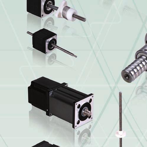
25 NEMA Size 8 (2 mm) Hybrid Stepper Motor Linear Actuators The NEMA 8 is our smallest hybrid linear actuator. This compact unit can be integrated into various applications to provide precise linear positioning while occupying less than 1 in 2 of mounting footprint and providing up to 1lbsF (44.5N) of continuous thrust. Ball screw versions are also available. Motor Characteristics Please contact Koco Motion US for custom products. Motor Voltage (V) Current (A) Resistance (Ω) Inductance (mh) Lead Wire No. Motor Length (mm) Available Lead Screws and Travel per Step Please contact Koco Motion US for custom products. Screw Dia. (inch) Screw Dia. (mm) Lead (inch) Lead (mm) Lead Code Travel Per 1.8 deg (mm)* AF AA B G M T.4 * values truncated 25
26 Quality Performance Flexibility Price NEMA Size 8 (2 mm) Dimensions ± ±.15 L.6 ± ±.2 6. ± ±2 4X M2 2.5MIN 12.6 ±.8 32 ±2 4 leads AWG 28# X ON 12.7mm THRU Solid Works 3D models available NEMA SIZE 8 EXTERNAL LINEAR ACTUATOR 6. ± ±1.66 ± ±.15 L ±.8 32 ±2 4 leads AWG # X M2 2.5 MIN..6 ± ±.2 M2 X.4 or 2-56 UNC NEMA SIZE 8 NON-CAPTIVE LINEAR ACTUATOR NOTE: All drawings are First Angle Projection ISO Standard. Hybrid Stepper Motor Linear Actuator Systems TECHNICAL SUPPORT:
27 NEMA Size 8 (2 mm) Speed Thrust Curves NEMA 8 SINGLE-STACK ROTARY SPEED Thrust (N) Size Force vs. Rotary Speed, 24VDC Chopper Driver 4. Operating above the *Recommended Load Limit decreases life expectancy due to increased nut wear (more backlash) 3. AA.696mm 2. B mm *RECOMMENDED LOAD LIMIT G 2.mm M 4.mm T 8.mm () (5) (1) (15) (2) (25) (3) (35) (4) (Pulse Speed) (pps) Rotary Speed (rpm) Thrust (lbsf)
28 Quality Performance Flexibility Price NEMA Size 8 (2 mm) Speed Thrust Curves (continued) NEMA 8 SINGLE-STACK LINEAR SPEED Thrust (N) Size Force vs. Linear Speed, 24VDC Chopper Driver Operating above the *Recommended Load Limit decreases life expectancy due to increased nut wear (more backlash) AA.696mm *RECOMMENDED LOAD LIMIT B mm G 2.mm M 4.mm T 8.mm Linear Speed (mm/s) Thrust (lbs F) Hybrid Stepper Motor Linear Actuator Systems TECHNICAL SUPPORT:
29 NEMA Size 8 (2 mm) Speed Thrust Curves (continued) NEMA 8 DOUBLE-STACK ROTARY SPEED Thrust (N) Size Force vs. Rotary Speed, 24VDC Chopper Driver 4. Operating above the *Recommended Load Limit decreases life expectancy due to increased nut wear (more backlash) 3. AA.696mm 2. B mm G 2.mm *RECOMMENDED LOAD LIMIT M 4.mm T 8.mm () (5) (1) (15) (2) (25) (3) (35) (4) (Pulse Speed) (pps) Rotary Speed (rpm) Thrust (lbsf)
30 Quality Performance Flexibility Price NEMA Size 8 (2 mm) Speed Thrust Curves (continued) NEMA 8 DOUBLE-STACK LINEAR SPEED Thrust (N) Size Force vs. Linear Speed, 24VDC Chopper Driver AA.696mm Operating above the *Recommended Load Limit decreases life expectancy due to increased nut wear (more backlash) *RECOMMENDED LOAD LIMIT B mm G 2.mm M 4.mm T 8.mm Linear Speed (mm/s) Thrust (lbs F) Hybrid Stepper Motor Linear Actuator Systems TECHNICAL SUPPORT:
31 NEMA Size 8 (2 mm) End Machining Options Standard Lead Screw End Machining Threaded End Metric End: UNC End: M2 X UNC Smooth End 2mm ± " ±.1 None - NEMA Size 8 (2 mm) Anti-Backlash Nut 31
32 Quality Performance Flexibility Price NEMA Size 8 (2 mm) Encoder Options EK1 ENCODER SINGLE ENDED OUTPUT EK1 ENCODER DIFFERENTIAL OUTPUT Encoder Options EK1 Line Count Single Ended Differential A B C D E F G H I J Custom Encoder or Custom Line Count: EC 32 For Encoder Ready Motors: ER1 Please refer to our website for complete encoder specifications: Hybrid Stepper Motor Linear Actuator Systems TECHNICAL SUPPORT:
 of the NEMA 8. Ball screw versions are also available. Motor Characteristics Please contact Koco Motion US for custom products.")
33 NEMA Size 11 (28 mm) Hybrid Stepper Motor Linear Actuators The NEMA 11 hybrid linear actuator occupies a mounting footprint of slightly above 1 in 2 but provides over 3X the continuous thrust (33lbsF/15N) of the NEMA 8. Ball screw versions are also available. Motor Characteristics Please contact Koco Motion US for custom products. Motor Voltage (V) Current (A) Resistance (Ω) Inductance (mh) Lead Wire No. Motor Length (mm) Available Lead Screws and Travel per Step Please contact Koco Motion US for custom products. Screw Dia. (inch) Screw Dia. (mm) Lead (inch) Lead (mm) Lead Code Travel Per 1.8 deg (mm)* A D K R X.58 * values truncated 33
34 Quality Performance Flexibility Price NEMA Size 11 (28 mm) Dimensions ±.6 23 ±.15 L.6 ± ±.2 6. ± ±2 4X M MIN ±.8 32 ±2 4 leads AWG 26# X 3.2 THRU ON 12.7mm Solid Works 3D models available NEMA SIZE 11 EXTERNAL LINEAR ACTUATOR ±.6 23 ± ± ±1 L X M MIN ±.8 32 ±2 4 leads AWG 26#.6 ± ±.2 M3 X.5 or 4-4 UNC NEMA SIZE 11 NON-CAPTIVE LINEAR ACTUATOR NOTE: All drawings are First Angle Projection ISO Standard. Hybrid Stepper Motor Linear Actuator Systems TECHNICAL SUPPORT:
35 NEMA Size 11 (28 mm) Speed Thrust Curves NEMA 11 SINGLE-STACK ROTARY SPEED Thrust (N) Size Force vs. Rotary Speed, 24VDC Chopper Driver Operating above the *Recommended Load Limit decreases life expectancy due to increased nut wear (more backlash) A.635mm *RECOMMENDED LOAD LIMIT D 1.27mm K 2.54mm R 5.8mm X 1.16mm () (5) (1) (15) (2) (25) (3) (Pulse Speed) (pps) Rotary Speed (rpm) Thrust (lbsf)
36 Quality Performance Flexibility Price NEMA Size 11 (28 mm) Speed Thrust Curves (continued) NEMA 11 SINGLE-STACK LINEAR SPEED Thrust (N) Size Force vs. Linear Speed, 24VDC Chopper Driver Operating above the *Recommended Load Limit decreases life expectancy due to increased nut wear (more backlash) A.635mm *RECOMMENDED LOAD LIMIT D 1.27mm K 2.54mm R 5.8mm X 1.16mm Linear Speed (mm/s) Thrust (lbs F) Hybrid Stepper Motor Linear Actuator Systems TECHNICAL SUPPORT:
37 NEMA Size 11 (28 mm) Speed Thrust Curves (continued) NEMA 11 DOUBLE-STACK ROTARY SPEED Thrust (N) Size Force vs. Rotary Speed, 24VDC Chopper Driver 25. Operating above the *Recommended Load Limit decreases life expectancy due to increased nut wear (more backlash) 2. A.635mm 15. D 1.27mm 1. *RECOMMENDED LOAD LIMIT K 2.54mm R 5.8mm X 1.16mm () (5) (1) (15) (2) (25) (3) (35) (4) (Pulse Speed) (pps) Rotary Speed (rpm) Thrust (lbsf)
38 Quality Performance Flexibility Price NEMA Size 11 (28 mm) Speed Thrust Curves (continued) NEMA 11 DOUBLE-STACK LINEAR SPEED Thrust (N) Size Force vs. Linear Speed, 24VDC Chopper Driver A.635mm Operating above the *Recommended Load Limit decreases life expectancy due to increased nut wear (more backlash) D 1.27mm *RECOMMENDED LOAD LIMIT K 2.54mm R 5.8mm X 1.16mm Linear Speed (mm/s) Thrust (lbs F) Hybrid Stepper Motor Linear Actuator Systems TECHNICAL SUPPORT:
39 NEMA Size 11 (28 mm) End Machining Options Standard Lead Screw End Machining Threaded End Metric End: UNC End: M3 X UNC Smooth End 3mm ± " ±.1 None - NEMA Size 11 (28 mm) Anti-Backlash Nut 39
40 Quality Performance Flexibility Price NEMA Size 11 (28 mm) Encoder Options EK1 ENCODER SINGLE ENDED OUTPUT EK1 ENCODER DIFFERENTIAL OUTPUT EK2 ENCODER SINGLE ENDED OUTPUT EK2 ENCODER DIFFERENTIAL OUTPUT 4 Encoder Options EK1 Line Count Single Ended Differential A B C D E F G H I J EK2 Line Count Single Ended Differential A B C D E F G H I Custom Encoder or Custom Line Count: EC For Encoder Ready Motors: ER1/ER2 For EK2 with Index: Add I as a suffix. For Example, for EK2, 512 line count, with Differential, and Index: EK2GI Please refer to our website for complete encoder specifications: Hybrid Stepper Motor Linear Actuator Systems TECHNICAL SUPPORT:
 Current (A) Resistance (Ω) Inductance (mh) Lead Wire No.")
41 NEMA Size 14 (35 mm) Hybrid Motor Linear Actuators The NEMA 14 hybrid precision linear actuator provides up to 52 lbsf (23N) of continuous thrust. A Captive version is available in this frame size. Ball screw versions are also available. Motor Characteristics Please contact Koco Motion US for custom products. Motor Voltage (V) Current (A) Resistance (Ω) Inductance (mh) Lead Wire No. Motor Length (mm) Available Lead Screws and Travel per Step Please contact Koco Motion US for custom products. 41 Screw Dia. (inch) Screw Dia. (mm) Lead (inch) Lead [mm] Lead Code Travel Per 1.8 deg (mm) Travel Per deg (mm)* AA B D F J K Q S U W Y * values truncated
42 Quality Performance Flexibility Price NEMA Size 14 (35 mm) Dimensions ±.1 26 ±.2 L 6. ± ±2 4X M3 4MIN ±.8 32 ±2 4 leads AWG 26# ±.1 2 ± x ON THRU Solid Works 3D models available 42 NEMA SIZE 14 EXTERNAL LINEAR ACTUATOR ±.1 26 ±.2 6. ± ±1 L X M ±.8 32 ±2 4 leads AWG #26 4 MIN..7 ± ±.2 M4 X.7 or 8-32 UNC NEMA SIZE 14 NON-CAPTIVE LINEAR ACTUATOR NOTE: All drawings are First Angle Projection ISO Standard. Hybrid Stepper Motor Linear Actuator Systems TECHNICAL SUPPORT:
43 NEMA Size 14 (35 mm) Dimensions (continued) L.24 6 A ±.1 26 ±.2 B ±.8 32 ±2 4 leads AWG #26.6 ± ± M6X1. or 8-32 UNC 4X M3 THRU Stroke B inch (mm) Dimension A (mm) Dimension L (mm).5 (12.7) (19.5) (25.4) (31.8) (38.1) (5.8) (63.5) 87.5 Single stack motor 35 mm Double stack motor 49 mm Solid Works 3D models available 43 NEMA 14 CAPTIVE LINEAR ACTUATOR NOTE: All drawings are First Angle Projection ISO Standard.
44 Quality Performance Flexibility Price NEMA Size 14 (35 mm) Speed Thrust Curves NEMA 14 SINGLE-STACK ROTARY SPEED Thrust (N) Size Force vs. Rotary Speed, 24VDC Chopper Driver Operating above the *Recommended Load Limit decreases life expectancy due to increased nut wear (more backlash) AA.69mm B 1.219mm D 1.27mm *RECOMMENDED LOAD LIMIT F 1.588mm J 2.438mm K 2.54mm () (5) (1) (15) (2) (25) (3) (Pulse Speed) (pps) Rotary Speed (rpm) Thrust (lbsf) Hybrid Stepper Motor Linear Actuator Systems TECHNICAL SUPPORT:
45 NEMA Size 14 (35 mm) Speed Thrust Curves (continued) NEMA 14 SINGLE-STACK ROTARY SPEED Thrust (N) Size Force vs. Rotary Speed, 24VDC Chopper Driver 4 L 3.175mm 2 Q mm S 6.35mm U 8.382mm W mm () (5) (1) (15) (2) (25) (3) (Pulse Speed) (pps) Rotary Speed (rpm) Thrust (lbsf)
46 Quality Performance Flexibility Price NEMA Size 14 (35 mm) Speed Thrust Curves (continued) NEMA 14 SINGLE-STACK LINEAR SPEED Thrust (N) Size Force vs. Linear Speed, 24VDC Chopper Driver AA.69mm Operating above the *Recommended Load Limit decreases life expectancy due to increased nut wear (more backlash) B 1.219mm *RECOMMENDED LOAD LIMIT D 1.27mm F 1.588mm J 2.438mm K 2.54mm Linear Speed (mm/s) Thrust (lbsf) Hybrid Stepper Motor Linear Actuator Systems TECHNICAL SUPPORT:
47 NEMA Size 14 (35 mm) Speed Thrust Curves (continued) NEMA 14 SINGLE-STACK LINEAR SPEED Thrust (N) Size Force vs. Linear Speed, 24VDC Chopper Driver 6 L 3.175mm 4 Q mm S 6.35mm W mm U 8.382mm Linear Speed (mm/s) Thrust (lbsf)
48 Quality Performance Flexibility Price NEMA Size 14 (35 mm) Speed Thrust Curves (continued) NEMA 14 DOUBLE-STACK ROTARY SPEED Thrust (N) Size Force vs. Rotary Speed, 24VDC Chopper Driver AA.69mm B 1.219mm D 1.27mm F 1.588mm J 2.438mm *RECOMMENDED LOAD LIMIT Operating above the *Recommended Load Limit decreases life expectancy due to increased nut wear (more backlash) () (5) (1) (15) (2) (25) (3) (Pulse Speed) (pps) Rotary Speed (rpm) Thrust (lbsf) Hybrid Stepper Motor Linear Actuator Systems TECHNICAL SUPPORT:
49 NEMA Size 14 (35 mm) Speed Thrust Curves (continued) NEMA 14 DOUBLE-STACK ROTARY SPEED Thrust (N) Size Force vs. Rotary Speed, 24VDC Chopper Driver 5 Operating above the *Recommended Load Limit decreases life expectancy due to increased nut wear (more backlash) K 2.54mm *RECOMMENDED LOAD LIMIT Q mm S 6.35mm U 8.382mm W mm () (5) (1) (15) (2) (25) (3) (Pulse Speed) (pps) Rotary Speed (rpm) Thrust (lbsf)
50 Quality Performance Flexibility Price NEMA Size 14 (35 mm) Speed Thrust Curves (continued) NEMA 14 DOUBLE-STACK LINEAR SPEED Thrust (N) Size Force vs. Linear Speed, 24VDC Chopper Driver AA.69mm B 1.219mm D 1.27mm Operating above the *Recommended Load Limit decreases life expectancy due to increased nut wear (more backlash) F 1.588mm J 2.438mm *RECOMMENDED LOAD LIMIT Linear Speed (mm/s) Thrust (lbsf) Hybrid Stepper Motor Linear Actuator Systems TECHNICAL SUPPORT:
51 NEMA Size 14 (35 mm) Speed Thrust Curves (continued) NEMA 14 DOUBLE-STACK LINEAR SPEED Thrust (N) Size Force vs. Linear Speed, 24VDC Chopper Driver K 2.54mm 15 Operating above the *Recommended Load Limit decreases life expectancy due to increased nut wear (more backlash) 1 *RECOMMENDED LOAD LIMIT Q mm S 6.35mm U 8.382mm W mm Linear Speed (mm/s) Thrust (lbsf)
52 Quality Performance Flexibility Price NEMA Size 14 (35 mm) End Machining Options Standard Lead Screw End Machining Threaded End Metric End: UNC End: M4 X.7mm 8-32 UNC Smooth End 4mm ± " ±.1 None - Captive Rod End Machining Metric End: UNC End: M6 X UNC NEMA Size 14 (35 mm) Anti-Backlash Nut 52 Hybrid Stepper Motor Linear Actuator Systems TECHNICAL SUPPORT:
53 NEMA Size 14 (35 mm) Encoder Options EK1 ENCODER SINGLE ENDED OUTPUT EK1 ENCODER DIFFERENTIAL OUTPUT EK2 ENCODER SINGLE ENDED OUTPUT EK2 ENCODER DIFFERENTIAL OUTPUT Encoder Options EK1 Line Count Single Ended Differential A B C D E F G H I J 53 EK2 Line Count Single Ended Differential A B C D E F G H I Custom Encoder or Custom Line Count: EC For Encoder Ready Motors: ER1/ER2 For EK2 with Index: Add I as a suffix. For Example, for EK2, 512 line count, with Differential, and Index: EK2GI Please refer to our website for complete encoder specifications:


54 Quality Performance Flexibility Price NEMA Size 17 (42 mm) Hybrid Stepper Motor Linear Actuators The NEMA 17 hybrid precision linear actuator provides up to 6lbsF (266N) of continuous thrust. A Captive version is available in this frame size. Ball screw versions are also available. Motor Characteristics Please contact Koco Motion US for custom products. Motor Voltage (V) Current (A) Resistance (Ω) Inductance (mh) Lead Wire No. Motor Length (mm) Available Lead Screws and Travel per Step Please contact Koco Motion US for custom products. 54 Screw Dia. Screw Dia. Lead Lead Lead Travel Per Step Travel Per Step (inch) (mm) (inch) (mm) 1.8 deg deg (mm)* AA B D F J K Q S U W Y Custom Lead Screw DIA Available for NEMA 17 * values truncated.375 DIA shaft available with external shaft version Hybrid Stepper Motor Linear Actuator Systems TECHNICAL SUPPORT:
55 NEMA Size 17 (42 mm) Dimensions ±.8 31 ±.2 L.7 ± ±.2 6. ± ±2 4X M3 4 MIN ±.8 32 ±2 4 leads AWG # X 3.2 THRU ON 19.5mm Solid Works 3D models available NEMA SIZE 17 EXTERNAL LINEAR ACTUATOR 55 NOTE: All drawings are First Angle Projection ISO Standard.
56 Quality Performance Flexibility Price NEMA Size 17 (42 mm) Dimensions (continued) ±.8 31 ±.2 6. ± ±1 L.7 ± ± ±.8 31 ±.2 L.24 6 A ± ± B M4 X.7 or 8-32 UNC 4X M3 4MIN ±.8 32 ±2 4 leads AWG #26 NEMA SIZE 17 NON-CAPTIVE LINEAR ACTUATOR Solid Works 3D models available X M3 THRU 12.6 ±.8 32 ±2 4 leads AWG #26 M6X1. or 8-32UNC Stroke B inch (mm) Dimension A (mm).5 (12.7) (19.5) (25.4) (31.8) (38.1) (5.8) (63.5) 87.5 Dimension L (mm) Single stack motor 35 mm Double stack motor 49 mm NEMA SIZE 17 CAPTIVE LINEAR ACTUATOR NOTE: All drawings are First Angle Projection ISO Standard. Hybrid Stepper Motor Linear Actuator Systems TECHNICAL SUPPORT:
57 NEMA Size 17 (42 mm) Speed Thrust Curves NEMA 17 SINGLE-STACK ROTARY SPEED Thrust (N) Size Force vs. Rotary Speed, 24VDC Chopper Driver AA.69mm D 1.27mm B 1.219mm F 1.588mm J 2.438mm *RECOMMENDED LOAD LIMIT Operating above the *Recommended Load Limit decreases life expectancy due to increased nut wear (more backlash) () (5) (1) (15) (2) (25) (3) (35) (4) (Pulse Speed) (pps) Rotary Speed (rpm) Thrust (lbsf)
58 Quality Performance Flexibility Price NEMA Size 17 (42 mm) Speed Thrust Curves (continued) NEMA 17 SINGLE-STACK ROTARY SPEED Thrust (N) Size Force vs. Rotary Speed, 24VDC Chopper Driver K 2.54mm Operating above the *Recommended Load Limit decreases life expectancy due to increased nut wear (more backlash) *RECOMMENDED LOAD LIMIT L 3.175mm Q mm S 6.35mm U 8.382mm W mm () (5) (1) (15) (2) (25) (3) (35) (4) (Pulse Speed) (pps) Rotary Speed (rpm) Thrust (lbsf) Hybrid Stepper Motor Linear Actuator Systems TECHNICAL SUPPORT:
59 NEMA Size 17 (42 mm) Speed Thrust Curves (continued) NEMA 17 SINGLE-STACK LINEAR SPEED Thrust (N) Size Force vs. Linear Speed, 24VDC Chopper Driver AA.69mm Operating above the *Recommended Load Limit decreases life expectancy due to increased nut wear (more backlash) 2 B 1.219mm F 1.588mm D 1.27mm *RECOMMENDED LOAD LIMIT J 2.438mm Linear Speed (mm/s) Thrust (lbsf)
60 Quality Performance Flexibility Price NEMA Size 17 (42 mm) Speed Thrust Curves (continued) NEMA 17 SINGLE-STACK LINEAR SPEED Thrust (N) Size Force vs. Linear Speed, 24VDC Chopper Driver Operating above the *Recommended Load Limit decreases life expectancy due to increased nut wear (more backlash) *RECOMMENDED LOAD LIMIT K 2.54mm Q mm L 3.175mm S 6.35mm U 8.382mm W mm Linear Speed (mm/s) Thrust (lbsf) Hybrid Stepper Motor Linear Actuator Systems TECHNICAL SUPPORT:
61 NEMA Size 17 (42 mm) Speed Thrust Curves (continued) NEMA 17 DOUBLE-STACK ROTARY SPEED Thrust (N) Size Force vs. Rotary Speed, 24VDC Chopper Driver AA.69mm B 1.219mm 6 D 1.27mm 4 F 1.588mm 2 J 2.438mm K 2.54mm *RECOMMENDED LOAD LIMIT Operating above the *Recommended Load Limit decreases life expectancy due to increased nut wear (more backlash) () (25) (5) (75) (1) (125) (15) (175) (2) (Pulse Speed) (pps) Rotary Speed (rpm) Thrust (lbsf)
62 Quality Performance Flexibility Price NEMA Size 17 (42 mm) Speed Thrust Curves (continued) NEMA 17 DOUBLE-STACK ROTARY SPEED Thrust (N) Size Force vs. Rotary Speed, 24VDC Chopper Driver Operating above the *Recommended Load Limit decreases life expectancy due to increased nut wear (more backlash) L 3.175mm Q mm *RECOMMENDED LOAD LIMIT S 6.35mm U 8.382mm W mm Y 12.7mm () (25) (5) (75) (1) (125) (15) (175) (2) (Pulse Speed) (pps) Rotary Speed (rpm) Thrust (lbsf) Hybrid Stepper Motor Linear Actuator Systems TECHNICAL SUPPORT:
63 NEMA Size 17 (42 mm) Speed Thrust Curves (continued) NEMA 17 DOUBLE-STACK LINEAR SPEED Thrust (N) Size Force vs. Linear Speed, 24VDC Chopper Driver AA.69mm B 1.219mm D 1.27mm F 1.588mm J 2.438mm K 2.54mm Operating above the *Recommended Load Limit decreases life expectancy due to increased nut wear (more backlash) *RECOMMENDED LOAD LIMIT Linear Speed (mm/s) Thrust (lbsf)
64 Quality Performance Flexibility Price NEMA Size 17 (42 mm) Speed Thrust Curves (continued) NEMA 17 DOUBLE-STACK LINEAR SPEED Thrust (N) Size Force vs. Linear Speed, 24VDC Chopper Driver L 3.175mm Operating above the *Recommended Load Limit decreases life expectancy due to increased nut wear (more backlash) Q mm S 6.35mm U 8.382mm *RECOMMENDED LOAD LIMIT W mm Y 12.7mm Linear Speed (mm/s) Thrust (lbsf) Hybrid Stepper Motor Linear Actuator Systems TECHNICAL SUPPORT:
65 NEMA Size 17 (42 mm) End Machining Options Standard Lead Screw End Machining Threaded End Metric End: UNC End: M4 X.7mm 8-32 UNC Smooth End 4mm ± " ±.1 None - Captive Rod End Machining Metric End: UNC End: M6 X UNC 65 NEMA Size 17 (42 mm) Anti-Backlash Nut
66 Quality Performance Flexibility Price NEMA Size 17 (42 mm) Encoder Options EK1 ENCODER SINGLE ENDED OUTPUT EK1 ENCODER DIFFERENTIAL OUTPUT EK2 ENCODER SINGLE ENDED OUTPUT EK2 ENCODER DIFFERENTIAL OUTPUT 66 Encoder Options EK1 Line Count Single Ended Differential A B C D E F G H I J EK2 Line Count Single Ended Differential A B C D E F G H I Custom Encoder or Custom Line Count: EC For Encoder Ready Motors: ER1/ER2 For EK2 with Index: Add I as a suffix. For Example, for EK2, 512 line count, with Differential, and Index: EK2GI Please refer to our website for complete encoder specifications: Hybrid Stepper Motor Linear Actuator Systems TECHNICAL SUPPORT:

67 NEMA Size 23 (57 mm) Hybrid Stepper Motor Linear Actuators The NEMA 23 hybrid precision linear actuator is capable of 2lbsF (89N) of continuous thrust. A Captive version is available in this frame size. Ball screw versions are also available. Motor Characteristics Please contact Koco Motion US for custom products. Motor Voltage (V) Current (A) Resistance (Ω) Inductance (mh) Lead Wire No. Motor Length (mm) Available Lead Screws and Travel per Step Please contact Koco Motion US for custom products. Screw Dia. (inch) Screw Dia. (mm) Lead (inch) Lead (mm) Lead Code Travel Per 1.8 deg (mm) Travel Per deg (mm)* A D F H K L P R S V W Y Z Custom Lead Screw DIA Available for NEMA 23 * values truncated.625 DIA shaft available with external shaft version 67
68 Quality Performance Flexibility Price NEMA Size 23 (57 mm) Dimensions L 6. ± ± ± ±.25.6 ± ± ± ±.5 4X 5.1 THRU 12.6 ±.8 32 ±2 4 leads AWG # X.14 ON 22.2mm 3.5 THRU Solid Works 3D models available NEMA SIZE 23 EXTERNAL LINEAR ACTUATOR ± ±.25 L 6. ± ±1.6 ± ± ± ±.5 4X THRU 12.6 ±.8 32 ±2 4 leads AWG # M6 X 1. or 1/4-2 UNC NEMA SIZE 23 NON-CAPTIVE LINEAR ACTUATOR NOTE: All drawings are First Angle Projection ISO Standard. Hybrid Stepper Motor Linear Actuator Systems TECHNICAL SUPPORT:
69 NEMA Size 23 (57 mm) Dimensions (continued) ± ±.25 L.24 6 A ± ±.2 B 1.5 ± ± X M4 THRU 12.6 ±.8 32 ±2 4 leads AWG # M1X1.5 or 1/4-2 UNC Stroke B inch (mm) Dimension A (mm).5 (12.7) (19.5) (25.4) (31.8) (38.1) (5.8) (63.5) 96.5 Dimension L (mm) Single stack motor 47 mm Double stack motor 66 mm NEMA SIZE 23 CAPTIVE LINEAR ACTUATOR Solid Works 3D models available 69 NOTE: All drawings are First Angle Projection ISO Standard.
70 Quality Performance Flexibility Price NEMA Size 23 (57 mm) Speed Thrust Curves NEMA 23 SINGLE-STACK ROTARY SPEED Thrust (N) Size Force vs. Rotary Speed, 48VDC Chopper Driver A.635mm D 1.27mm Operating above the *Recommended Load Limit decreases life expectancy due to increased nut wear (more backlash) F 1.588mm *RECOMMENDED LOAD LIMIT H 2.182mm K 2.54mm L 3.175mm () (5) (1) (15) (2) (25) (3) (Pulse Speed) (pps) Rotary Speed (rpm) Thrust (lbsf) Hybrid Stepper Motor Linear Actuator Systems TECHNICAL SUPPORT:
71 NEMA Size 23 (57 mm) Speed Thrust Curves (continued) NEMA 23 SINGLE-STACK ROTARY SPEED Thrust (N) Size Force vs. Rotary Speed, 48VDC Chopper Driver P 4.242mm 2 R 5.8mm S 6.35mm V 9.525mm W mm Y 12.7mm Z 25.4mm () (5) (1) (15) (2) (25) (3) (Pulse Speed) (pps) Rotary Speed (rpm) Thrust (lbsf)
72 Quality Performance Flexibility Price NEMA Size 23 (57 mm) Speed Thrust Curves (continued) NEMA 23 SINGLE-STACK LINEAR SPEED Thrust (N) Size Force vs. Linear Speed, 48VDC Chopper Driver A.635mm D 1.27mm Operating above the *Recommended Load Limit decreases life expectancy due to increased nut wear (more backlash) *RECOMMENDED LOAD LIMIT H 2.182mm F 1.588mm K 2.54mm L 3.175mm Linear Speed (mm/s) Thrust (lbsf) Hybrid Stepper Motor Linear Actuator Systems TECHNICAL SUPPORT:
73 NEMA Size 23 (57 mm) Speed Thrust Curves (continued) NEMA 23 SINGLE-STACK LINEAR SPEED Thrust (N) Size Force vs. Linear Speed, 48VDC Chopper Driver P 4.242mm R 5.8mm S 6.35mm V 9.525mm W mm Y 12.7mm Z 25.4mm Linear Speed (mm/s) Thrust (lbsf)
74 Quality Performance Flexibility Price NEMA Size 23 (57 mm) Speed Thrust Curves (continued) NEMA 23 DOUBLE-STACK ROTARY SPEED Thrust (N) Size Force vs. Rotary Speed, 48VDC Chopper Driver A.635mm D 1.27mm F 1.588mm H 2.182mm K 2.54mm L 3.175mm *RECOMMENDED LOAD LIMIT Operating above the *Recommended Load Limit decreases life expectancy due to increased nut wear (more backlash) () (5) (1) (15) (2) (25) (3) (Pulse Speed) (pps) Rotary Speed (rpm) Thrust (lbsf) Hybrid Stepper Motor Linear Actuator Systems TECHNICAL SUPPORT:
75 NEMA Size 23 (57 mm) Speed Thrust Curves (continued) NEMA 23 DOUBLE-STACK ROTARY SPEED Thrust (N) Size Force vs. Rotary Speed, 48VDC Chopper Driver Operating above the *Recommended Load Limit decreases life expectancy due to increased nut wear (more backlash) P 4.242mm *RECOMMENDED LOAD LIMIT R 5.8mm S 6.35mm V 9.525mm W mm Y 12.7mm Z 25.4mm () (5) (1) (15) (2) (25) (3) (Pulse Speed) (pps) Rotary Speed (rpm) Thrust (lbsf)
76 Quality Performance Flexibility Price NEMA Size 23 (57 mm) Speed Thrust Curves (continued) NEMA 23 DOUBLE-STACK LINEAR SPEED Thrust (N) Size Force vs. Linear Speed, 48VDC Chopper Driver A.635mm D 1.27mm F 1.588mm Operating above the *Recommended Load Limit decreases life expectancy due to increased nut wear (more backlash) H 2.182mm K 2.54mm *RECOMMENDED LOAD LIMIT L 3.175mm Linear Speed (mm/s) Thrust (lbsf) Hybrid Stepper Motor Linear Actuator Systems TECHNICAL SUPPORT:
77 NEMA Size 23 (57 mm) Speed Thrust Curves (continued) NEMA 23 DOUBLE-STACK LINEAR SPEED Thrust (N) Size Force vs. Linear Speed, 48VDC Chopper Driver Operating above the *Recommended Load Limit decreases life expectancy due to increased nut wear (more backlash) *RECOMMENDED LOAD LIMIT P 4.242mm R 5.8mm S 6.35mm V 9.525mm W mm Y 12.7mm Z 25.4mm Linear Speed (mm/s) Thrust (lbsf)

78 Quality Performance Flexibility Price NEMA Size 23 (57 mm) End Machining Options Standard Lead Screw End Machining Threaded End Metric End: UNC End: M6 X 1. 1/4-2 UNC Smooth End 6mm ± " ±.1 None - Captive Rod End Machining 78 Metric End: UNC End: M1 X 1.5 1/4-2 UNC NEMA Size 23 (57 mm) Anti-Backlash Nut Hybrid Stepper Motor Linear Actuator Systems TECHNICAL SUPPORT:
Precision Hybrid Stepper Linear Actuator Systems
 Precision Hybrid Stepper Linear Actuator Systems 2018 Distributed by Changzhou DINGS Electrical & Mechanical Co. Ltd. INTRODUCTION Motion Control Products Ltd., supplies quality leadscrew-style linear
Hybrid Stepper Motors
 DINGS Electrical & Mechanical Co., Ltd 3 Quality Performance Flexibility Price WHO IS DINGS? DINGS is a premier supplier of rotary and linear step motors. Based in the greater Shanghai, China area, we
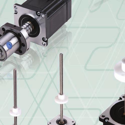
Hybrid stepper motor lead screw linear actuators
 Hybrid stepper motor lead screw linear actuators The DINGS brand of hybrid linear actuators come in six sizes, from 21 mm square to 87 mm square corresponding to size 8, size 11, size 14, size 17, size
Identifying the Motorized RGS part number codes when ordering
 RGS04 Motorized with 28000 Series Size11 DS RGS04 Linear Rail for Hybird 28000 Series Size 11 Double Stacks and RGS04 for 43000 Series Size 17 Single and Double Stacks (See Page 4) RGS04 Linear Rail with
MANTECH ELECTRONICS. Stepper Motors. Basics on Stepper Motors I. STEPPER MOTOR SYSTEMS OVERVIEW 2. STEPPING MOTORS
 MANTECH ELECTRONICS Stepper Motors Basics on Stepper Motors I. STEPPER MOTOR SYSTEMS OVERVIEW 2. STEPPING MOTORS TYPES OF STEPPING MOTORS 1. VARIABLE RELUCTANCE 2. PERMANENT MAGNET 3. HYBRID MOTOR WINDINGS
HSI Stepper Motor Theory
 HI tepper Motor Theory Motors convert electrical energy into mechanical energy. A stepper motor converts electrical pulses into specific rotational movements. The movement created by each pulse is precise
Introduction to hmtechnology
 Introduction to hmtechnology Today's motion applications are requiring more precise control of both speed and position. The requirement for more complex move profiles is leading to a change from pneumatic
43M4 n n n n n n. 43L4 n n n n n n. E43M4 n n n n n n. Bipolar 5 VDC 12 VDC. 550 ma 1.3 A 21.9 Ω 3.8 Ω mh mh W Total.
 HAYD: 2 756 744 KERK: 6 2 629 4 Series: Double Stack Stepper Motor Linear Actuator Haydon 4 Series Double Stack hybrid linear actuators offer greater performance. Double Stack Captive Shaft The versatile
Step Motor. Mechatronics Device Report Yisheng Zhang 04/02/03. What Is A Step Motor?
 Step Motor What is a Step Motor? How Do They Work? Basic Types: Variable Reluctance, Permanent Magnet, Hybrid Where Are They Used? How Are They Controlled? How To Select A Step Motor and Driver Types of
QMOT QSH5718 MANUAL. QSH mm 2.8A, 0.55Nm mm 2.8A, 1.01Nm mm 2.8A, 1.26Nm mm 2.8A, 1.
 QMOT STEPPER MOTORS MOTORS V 2.3 QMOT QSH5718 MANUAL + + QSH-5718-41-28-055 57mm 2.8A, 0.55Nm -51-28-101 57mm 2.8A, 1.01Nm -56-28-126 57mm 2.8A, 1.26Nm -76-28-189 57mm 2.8A, 1.89Nm + + TRINAMIC Motion
SOME FACTORS THAT INFLUENCE THE PERFORMANCE OF
 SOME FACTORS THAT INFLUENCE THE PERFORMANCE OF Authored By: Robert Pulford Jr. and Engineering Team Members Haydon Kerk Motion Solutions There are various parameters to consider when selecting a Rotary
Mini-MAG Positioning Products
 Mini-MAG Positioning Products Miniature Linear Stage The Mini-MAG (MMX) line of miniature linear stages blends the ultimate in performance, reliability, and value, delivering nearly twice the accuracy
QMOT Motor QSH4218 Manual 42mm QMOT motor family
 QMOT Motor QSH4218 Manual 42mm QMOT motor family Trinamic Motion Control GmbH & Co. KG Sternstraße 67 D 20357 Hamburg, Germany Phone +49-40-51 48 06 0 FAX: +49-40-51 48 06 60 http://www.trinamic.com INFO@TRINAMIC.COM
gear reduction. motor model number is determined by the following: O: Single 1: Double Motor Characteristics (1-99) Construction
 Construction") TEP OPERATIO & THEORY 1 KC tepping Motor Part umber. oncumulative positioning error (± % of step angle).. Excellent low speed/high torque characteristics without 1. tepping motor model number description
TEP OPERATIO & THEORY 1 KC tepping Motor Part umber. oncumulative positioning error (± % of step angle).. Excellent low speed/high torque characteristics without 1. tepping motor model number description
High-Efficiency AR Series. RK Series /0.72 /Geared. CRK Series. RBK Series. CMK Series. 2-Phase Stepping Motors A-278.
 A Stepping Motors Stepping Motors Introduction A-2 Introduction AC Power Supply Input Stepping Motor and Driver Packages A-17 DC Power Supply Input Stepping Motor and Driver Packages Stepping Motors (Motor
Stepper Motors ver ver.5
 A Stepper s Stepper s A-1 Overview... A-2 Overview and... A-15 & Stepper and RK Series A-16 RK... A-47... A-51 Stepper Series A-52 Stepper Series A-8 See Full Product Details Online www.orientalmotor.com
Application Note : Comparative Motor Technologies
 Application Note : Comparative Motor Technologies Air Motor and Cylinders Air Actuators use compressed air to move a piston for linear motion or turn a turbine for rotary motion. Responsiveness, speed
TurboDisc Stepper Motors
 TurboDisc Stepper Motors P43 P532 P31 P11 P1 The TurboDisc provides exceptional dynamic performance unparalleled by any other stepper on the market. The unique thin disc magnet enables finer step resolutions
QMOT STEPPER MOTORS MOTORS
 QMOT STEPPER MOTORS MOTORS V 1.08 QMOT QSH6018 MANUAL + + QSH-6018-45-28-110 60mm 2.8A, 1.10 Nm -56-28-165 60mm 2.8A, 1.65 Nm -65-28-210 60mm 2.8A, 2.10 Nm + + -86-28-310 60mm 2.8A, 3.10 Nm TRINAMIC Motion
Stopping Accuracy of Brushless
 Stopping Accuracy of Brushless Features of the High Rigidity Type DGII Series Hollow Rotary Actuator The DGII Series hollow rotary actuator was developed for positioning applications such as rotating a
LEAD SCREWS 101 A BASIC GUIDE TO IMPLEMENTING A LEAD SCREW ASSEMBLY FOR ANY DESIGN
 LEAD SCREWS 101 A BASIC GUIDE TO IMPLEMENTING A LEAD SCREW ASSEMBLY FOR ANY DESIGN Released by: Keith Knight Kerk Products Division Haydon Kerk Motion Solutions Lead Screws 101: A Basic Guide to Implementing
AS Series. RK Series. UMK Series ASX Series 0.36 /0.72. CRK Series. CMK Series 1.8. RBK Series. PK Series 1.
 A Stepping Motors Stepping Motors Introduction A-2 Introduction AC Input Stepping Motor and Driver Packages DC Input Stepping Motor and Driver Packages Stepping Motors (Motor Only) A-269 A-24 High Efficiency
Product Manual. 42BYGH40(M)-160-4A NEMA 17 Bipolar 5.18:1. Planetary Gearbox Stepper
-160-4A NEMA 17 Bipolar 5.18:1. Planetary Gearbox Stepper") Product Manual 42BYGH40(M)-160-4A NEMA 17 Bipolar 5.18:1 Planetary Gearbox Stepper Phidgets - Product Manual 42BYGH40(M)-160-4A NEMA 17 Bipolar 5.18:1 Planetary Gearbox Stepper Phidgets Inc. 2011 Contents
Product Manual 42BYGH40(M)-160-4A NEMA 17 Bipolar 5.18:1 Planetary Gearbox Stepper Phidgets - Product Manual 42BYGH40(M)-160-4A NEMA 17 Bipolar 5.18:1 Planetary Gearbox Stepper Phidgets Inc. 2011 Contents
QMOT Motor QSH4218 Manual 42mm QMOT motor family
 QMOT Motor QSH4218 Manual 42mm QMOT motor family Trinamic Motion Control GmbH & Co. KG Sternstraße 67 D 20357 Hamburg, Germany http://www.trinamic.com QSH4218 Manual (V1.03 /13-November-2007) 2 Table of
Primer. Stepper Motors
 Primer Stepper Motors Phidgets - Primer Manual Motors Phidgets Inc. 2011 Contents 4 Introduction 5 Types of Stepper Motors 7 Controlling the Stepper Motor 9 Selecting a Gearbox 10 Glossary of Terms Introduction
Ultra Series: Crossed Roller Ultra Precision Stages
 Ultra Series: Crossed Roller Ultra Precision Stages Bayside Motion Group, has developed Ultra Positioning Stages for applications requiring the ultimate in accuracy. Available with a linear motor, ball
St epping Mot or s C-i ORIENTAL MOTOR GENERAL CATALOG 2009/2010
 C-i ORIENTAL MOTOR GENERAL CATALOG 29/21 C Introduction C-2 Stepping Motor and Driver Packages AC Input Stepping Motor and Driver Packages DC Input Stepping Motors AC Input AS Series C-14 DC Input ASC
using Class 2-C (Centralizing) tolerances. Jack lift shaft lead tolerance is approximately 0.004" per foot.
 tolerances. Jack lift shaft lead tolerance is approximately 0.004 per foot.") WORM GEAR JACK MODELS WORM GEAR ACTIONJAC JACKS Jack systems are ruggedly designed and produced in standard models with load handling capacities from 1/4 ton to 100 tons. They may be used individually
WORM GEAR JACK MODELS WORM GEAR ACTIONJAC JACKS Jack systems are ruggedly designed and produced in standard models with load handling capacities from 1/4 ton to 100 tons. They may be used individually
Screw Driven automation tables
 automation tables Precise multi-axis positioning systems play an integral part in today s semiconductor, computer peripheral, solar power, flat panel, life sciences, lab automation, biomedical and electronics
300 & 400 Series Positioning Tables
 300 & 400 Series Positioning Tables 300 Series Introduction L-2 400 Series Introduction L-3 Specifications L-5 300 Series Dimensions L-6 400 Series Dimensions L-7 300 Series Motor Couplings L-8 300 Series
Application Information
 Moog Components Group manufactures a comprehensive line of brush-type and brushless motors, as well as brushless controllers. The purpose of this document is to provide a guide for the selection and application
Creating Linear Motion One Step at a Time
 Creating Linear Motion One Step at a Time In classic mechanical engineering, linear systems are typically designed using conventional mechanical components to convert rotary into linear motion. Converting
QMOT QSH4218 MANUAL. QSH mm 1A, 0.27Nm mm 1A, 0.35Nm mm 1A, 0.49Nm mm 2.8A, 0.40Nm V 1.
 QMOT STEPPER MOTORS MOTORS V 1.06 QMOT QSH4218 MANUAL + + QSH-4218-35-10-027 42mm 1A, 0.27Nm -41-10-035 42mm 1A, 0.35Nm -51-10-049 42mm 1A, 0.49Nm + + -47-28-040 42mm 2.8A, 0.40Nm TRINAMIC Motion Control
Artisan Technology Group is your source for quality new and certified-used/pre-owned equipment
 Artisan Technology Group is your source for quality new and certified-used/pre-owned equipment FAST SHIPPING AND DELIVERY TENS OF THOUSANDS OF IN-STOCK ITEMS EQUIPMENT DEMOS HUNDREDS OF MANUFACTURERS SUPPORTED
Technical Reference H-37
 tepper Technical Reference H-37 tructure of tepper The figures below show two cross-sections of a.72 stepper motor. The stepper motor consists primarily of two parts: a stator and rotor. The rotor is made
Drive / Mounting. A = None
 HAYD: 203 756 7441 Motorized and Non-Motorized LRS Linear Rail Systems available with a Haydon Hybrid 43000 Series Size 17 single and double stack linear actuator stepper motor or as an non-motorized linear
ServoRings TM - integrated rotary tables with high torque servo ring motor, high resolution ring encoder and high accuracy ring bearing
 ServoRings TM - integrated rotary tables with high torque servo ring motor, high resolution ring encoder and high accuracy ring bearing Operating principle ServoRing TM rotary tables use segmented three
Courtesy of Steven Engineering, Inc - (800) PATENTED
 PATENTED") PRECISION RING DRIVE SYSTEMS Based on Nexen s innovative Roller Pinion technology, Nexen Ring Drive Systems come complete with a precision grade, high capacity bearing and drive mechanism in a rigid housing.
PRECISION RING DRIVE SYSTEMS Based on Nexen s innovative Roller Pinion technology, Nexen Ring Drive Systems come complete with a precision grade, high capacity bearing and drive mechanism in a rigid housing.
Prepared By: Ahmad Firdaus Bin Ahmad Zaidi
 Prepared By: Ahmad Firdaus Bin Ahmad Zaidi A stepper motor is an electromechanical device which converts electrical pulses into discrete mechanical rotational movements. Stepper motor mainly used when
EMC-HD. C 01_2 Subheadline_15pt/7.2mm
 C Electromechanical 01_1 Headline_36pt/14.4mm Cylinder EMC-HD C 01_2 Subheadline_15pt/7.2mm 2 Elektromechanischer Zylinder EMC-HD Short product name Example: EMC 085 HD 1 System = ElectroMechanical Cylinder
Screw Driven automation tables
 automation tables Precise multi-axis positioning systems play an integral part in today s semiconductor, computer peripheral, solar power, flat panel, life sciences, lab automation, biomedical and electronics
MPPV-2, 4, 6, 8 Valve Instruction Manual Date:12/1/16
 MPPV-2, 4, 6, 8 Valve Instruction Manual Date:12/1/16 Valve Description System Control Options and Requirements Recommended Tube Type Thrust vs Speed Performance Curve Electrical Specs. Wiring Diagram
Frameless High Torque Motors. Product Brochure
 Frameless High Torque Motors Product Brochure Magnetic Innovations high torque motors are the right motors for your systems High dynamics High torque density High efficiency Optimal speed control High
Miniature Positioners linear motor and screw driven stages
 linear motor and screw driven stages Miniaturization of fiber optics, photonics, electronics and biomedical processes has driven the need for smaller and more efficient positioners. Parker offers numerous
ZETA advanced microstep drive. Microstepping systems - the next generation... Automation. Quicker settling following a speed change
 ZETA-2 advanced microstep drive Microstepping systems - the next generation... The new ZETA series drives from Parker represent a true revolution in microstep drive design. Incorporating breakthrough techniques
Step Motors & Drives. Hybrid Step Motors
 The typical step motor system consists of a step motor and a drive package that contains the control electronics and a power supply. The drive receives step and direction signals from an indexer or programmable
Servo Motors B-1. Introduction B-2. NX Series B-9. Accessories B-47
 B Servo Motors Servo Motors Introduction B-2 NX Series B-9 Accessories B-47 Introduction NX Accessories This catalog contains information necessary for informed product selection. Additional product details
Linear Actuator with Ball Screw Series OSP-E..S. Contents Description Overview Technical Data Dimensions 89
 Linear Actuator with Ball Screw Series OSP-E..S Contents Description Page Overview 79-82 Technical Data 83-88 Dimensions 89 79 The System Concept ELECTRIC LINEAR ACTUATOR FOR HIGH ACCURACY APPLICATIONS
QUESTION BANK SPECIAL ELECTRICAL MACHINES
 SEVENTH SEMESTER EEE QUESTION BANK SPECIAL ELECTRICAL MACHINES TWO MARK QUESTIONS 1. What is a synchronous reluctance 2. What are the types of rotor in synchronous reluctance 3. Mention some applications
Hybrid Control System, Alpha Step
 B Hybrid Control System, Alpha Step Hybrid Control System B-1 Overview... B-2 Overview Hybrid Control System Battery-Free, Absolute Sensor Equipped AZ Series... B-16 Electric Linear Slides EZS Series AZ
Kollmorgen Stepper Motor Overview
 Kollmorgen Stepper Motor Overview K O L L M O R G E N S T E P P E R M O T O R O V E R V I E W Kollmorgen offers a comprehensive range of stepper motor products including continous torque, high torque and
Rotary Series Rotary Series: Direct Drive Precision Stages
 Rotary Series Rotary Series: Direct Drive Precision Stages Parker Bayside s Direct Drive Rotary Stages feature a robust construction and high performance in a compact package, providing smooth, near-frictionless
HYBRID LINEAR ACTUATORS BASICS
 HYBRID LINEAR ACTUATORS BASICS TECHNICAL OVERVIEW Converting the rotary motion of a stepping motor into linear motion can be accomplished by several mechanical means, including rack and pinion, belts and
Stepper Motor Linear Actuators
 Stepper Motor Linear Actuators Pre-engineered lead screw assemblies and actuators for precision applications www.thomsonlinear.com Stepper Motor Linear Actuator Assemblies Combining cutting-edge motor
FTP Series HIGH FORCE ELECTRIC PRESS ACTUATOR
 FTP Series HIGH FORCE ELECTRIC PRESS ACTUATOR Ideal hydraulic press replacement Industry-leading power density Rugged and reliable Flexible and precise 952.500.6200 www.exlar.com 75 FTP Series High Force
Technical Explanation for Inverters
 CSM_Inverter_TG_E_1_2 Introduction What Is an Inverter? An inverter controls the frequency of power supplied to an AC motor to control the rotation speed of the motor. Without an inverter, the AC motor
Motor/Drive Configuration
 ZX900 Electrical Specifications Input Power Output Power Electrical specifications for the ZX900 series drive's input and output power are provided in this section. Voltage (Nominal) Voltage (Range) Frequency
Hollow shaft hybrid stepper
 C Hollow shaft hybrid stepper These Hollow shaft motor have 6 different sizes, from 20mm to 86mm. Each size has different stack lengths. Different sizes of inner holes, front and rear shafts can be provided.
AC Motors vs DC Motors. DC Motors. DC Motor Classification ... Prof. Dr. M. Zahurul Haq
 AC Motors vs DC Motors DC Motors Prof. Dr. M. Zahurul Haq http://teacher.buet.ac.bd/zahurul/ Department of Mechanical Engineering Bangladesh University of Engineering & Technology ME 6401: Advanced Mechatronics
Linear Drive with Toothed Belt Series OSP-E..B. Contents Description Overview Technical Data Dimensions Order Instructions 46
 Linear Drive with Toothed Belt Contents Description Page Overview 35-38 Technical Data 39-43 Dimensions 44-45 Order Instructions 46 35 The System Concept ELECTRIC LINEAR DRIVE FOR POINT-TO-POINT APPLICATIONS
Design Considerations
 Design Consideration RS Series PS Series GS Series * Rolled Ball Screw * Tapped Ball Nut * English Leads * English Diameters * Pre-loaded & Non-preloaded Nuts * Simple, Fixed and Rigid Housings * Available
Linear Drive with Ball Screw Drive Series OSP-E..SB
 Linear Drive with Ball Screw Drive Series OSP-E..SB Contents Description Data Sheet No. Page Overview 1.30.001E 47-50 Technical Data 1.30.002E-1 to 5 51-55 Dimensions 1.30.002E-6, -7 56-57 Order instructions
LINEAR ACTUATOR SYSTEMS
 LINEAR ACTUATOR SYSTEMS The LinFinity Linear Actuator is a system engineered to eliminate issues that plague ordinary linear actuators: Excessive friction and heat build up Too much noise Degrading accuracy
Unternehmensportrait. High Pole Servo. Stepper Motor basics vs. High Pole Servo
 High Pole Servo Stepper Motor basics vs High Pole Servo Stepper Motor types Hybrid-Stepper Motor Principal Construction like a BLDC (brushless DC Motor), but higher pole count Rotor and Stator silicon
HaydonKerk Motion SolutionsTM Phone: International: Stepper Motor Linear Actuators
 HaydonKerk Motion SolutionsTM www.haydonkerk.com Phone: 800.243.2715 International: 203.756.7441 Stepper Motor Linear Actuators Stepper Motor Linear Actuators: Product Summary Hybrid Linear Actuators Series
Frameless Torque Motor Series
 Frameless Torque Motor Series QUALITY AND SERVICE DELIVERED WORLDWIDE [ TECNOTION ] Tecnotion is the global authority on direct drive motor technology. We are the world s only unbundled manufacturer of
Linear Actuator with Toothed Belt Series OSP-E..B
 Linear Actuator with Toothed Belt Series OSP-E..B Contents Description Data Sheet No. Page Overview 1.20.001E 21-24 Technical Data 1.20.002E-1 to 5 25-29 Dimensions 1.20.002E-6 30 Order Instructions 1.20.002E-7
Rotary Direct Drive Motor Cartridge DDR
 www.danahermotion.net Rotary Direct Drive Motor Cartridge DDR Driven by Edition 04.2004 english DDR (Direct Drive Rotary) What is direct drive? Very simply it is the direct coupling of a torque motor to
BMS Series. DC Brushless Torque Motors. Slotless, brushless stator design provides zerocogging torque for unsurpassed velocity control
 BMS Series Rotary Motors BMS Series DC Brushless Torque Motors Slotless, brushless stator design provides zerocogging torque for unsurpassed velocity control Smoother velocity than with standard DC brushtype
PC-Series Precision Linear Actuators. Optimize Your Machine and Save Energy With Reliable, High Performance, Compact Actuators
 PC-Series Precision Linear Actuators Optimize Your Machine and Save Energy With Reliable, High Performance, Compact Actuators Make the Change to Electric Enjoy superior performance and save time and energy
Replace your belt, ball screw or rack and pinion mechanism with a simple and economical linear servo motor actuator
 LINEAR SERVO ECONO-SLIDE Ultimate Solution for High Throughput Precision Positioning Replace your belt, ball screw or rack and pinion mechanism with a simple and economical linear servo motor actuator
Six keys to achieving better precision in linear motion control applications
 profile Drive & Control Six keys to achieving better precision in linear motion control applications Achieving precise linear motion Consider these factors when specifying linear motion systems: Equipped
Frameless High Torque Motors. Product Brochure
 Frameless High Torque Motors Product Brochure Magnetic Innovations high torque motors are the right motors for your systems High dynamics High torque density High efficiency Optimal speed control High
Heavy Duty Ball Screw Linear Actuators
 Heavy Duty Ball Screw Linear Actuators Thrust From 2,000 to 25,000 lbf Heavy Wall Steel Construction Longest Life Simultaneous High Thrust with High Speed Piston with Rugged Anti Rotation Feature Sealed
AC Servo Motors and Servo Rated Gearheads
 AC Servo Motors and Servo Rated Gearheads for the automation industry Brushless Servo Motors 2 AC Servo Motors Baldor has been leading the way in energy efficient industrial motors since the 192 s. Baldor
!Servo Motors & Drives. !Gearmotors & Gearheads. !Linear & Rotary Positioning Stages. Ultra Series Product Manual
 !Servo Motors & Drives!Gearmotors & Gearheads!Linear & Rotary Positioning Stages Ultra Series Product Manual Ultra Series Product Manual Rev: 1 / 904 Please check www.baysidemotion.com for latest revisions.
B Hybrid rotary stepper motor
 B Hybrid rotary stepper motor Dings supply hybrid stepper motor of seven sizes - from 20 mm to 86 mm. Each size has different stack lengths. Planetary gearbox and encoder are available. For all motors
LS100 Series Positioning Tables
 LS100 Series Positioning Tables User s Guide A N A H E I M A U T O M A T I O N 4985 East Landon Drive Anaheim, CA 92807 e-mail: info@anaheimautomation.com (714) 992-6990 fax: (714) 992-0471 website: www.anaheimautomation.com
Kollmorgen Frameless Motor Selection Guide
 Kollmorgen Frameless Motor Selection Guide KBM Series Brushless Motors Kollmorgen. Every solution comes from a real understanding of OEM challenges. The ever-escalating demands of the marketplace mean
SHINANO KENSHI CORP. STEPPING MOTORS DC BRUSHLESS MOTORS DC SERVO MOTORS
 SHINANO KENSHI CORP. STEPPING MOTORS DC BRUSHLESS MOTORS DC SERVO MOTORS ISO-9000 & ISO-14000 Certified Since its inception in 1918, Shinano Kenshi Co., Ltd. of Japan has found innovative and creative
PROmech Series Miniature Linear Positioners. Catalog 8094/USA. Daedal
 PROmech Series Miniature Linear Positioners Catalog 8094/USA Daedal PROmech LP28 Miniature Linear Positioner PROmech LP28 Miniature Linear Positioner Features: Miniature Profile Optimal length to travel
Closed Loop Stepper Systems
 Closed Loop Stepper Systems E -Series High Performance Steppers The new ecl series introduces simple and precise closed loop control to Parker s microstepping product platform. Available in two driver
Precision Linear Actuators
 Precision Linear Actuators Linear Motion. Optimized. T Series Introduction The proven design of the T series precision linear actuators has found its way into thousands of applications throughout the world.
Quantum Series Size 17, 23, 34 and 56 Brushless Servo Motors Frameless and Housed Engineering Guide
 MACCON GmbH Kübachstr.9 D-81543 München Tel +49-89-65122()-21 Fax +49-89-655217 Quantum Series Size 17, 23, 34 and 56 Brushless Servo Motors Frameless and Housed Engineering Guide Selection Guide Quantum
Motorized Lead Screws
 Stepper Motor Linear Actuator Precision engineered to be compact, powerful, quiet and efficient New Motorized Lead Screws from combine a hybrid stepper motor and a precision lead screw together in one
Creating Linear Motion One Step at a Time Precision Linear Motion Accomplished Easily and Economically
 Creating Linear Motion One Step at a Time Precision Linear Motion Accomplished Easily and Economically How Is a Linear Actuator Sized? Sizing a linear actuator is quite easy once you understand the basic
Linear Actuator with Ball Screw Series OSP-E..S. Contents Description Overview Technical Data Dimensions 79
 Linear Actuator with Ball Screw Series OSP-E..S Contents Description Page Overview 71-74 Technical Data 75-78 Dimensions 79 71 The System Concept ELECTRIC LINEAR ACTUATOR FOR HIGH ACCURACY APPLICATIONS
New! Parallel Actuators. In-line Actuators. Controls. Contents. Programming
 Danaher Linear has long been the leader in ball bearing screws and linear actuators. This new line of Electrak programmable linear actuators offers an expanded range of performance in life, load carrying
Exlar Corporation 1470 Lake Drive West Chanhassen, MN TEL: General FAX: Order Only FAX:
 PRODUCT CATALOG The Global Leader in Actuator Technology Tritex II TM Line Voltage Linear and Rotary Electro-Mechanical Actuators For over a decade Exlar has been the global leader in actuator technology.
K Series Kit Motor Reliable and Compact Approach: Build your own high-performance motor
 Frameless K Series Kit Overview K Series Kit Motor Reliable and Compact Approach: Build your own high-performance motor Direct drive motion construction gives equipment designers the advantages of lower
Product and Company Overview
 Product and Company Overview Company History Founded in 1885 2015 marked 130 years of incorporation 12 Factories 2,850 Employees $500 Million in Revenue Quality is First and Foremost Quick Delivery (1-9
2005 Product Catalog
 2005 Product Catalog EXLAR Our Company At Exlar, we are very proud of our innovation and development of quality products. With our unique product offering, we have pushed the limits of conventional motion
L Series Lead Screw Step Motors
 L Series Lead Screw Step Motors Contents Introduction... 3 Screw Length Options... 4 LX08 Series... 5 LX08 Mechanical Data... 6 LX08 Specifications... 7 LX08 Performance Curves... 7 LX11 Series... 8 LX11
UNIT 7: STEPPER MOTORS
 UIT 7: TEPPER MOTOR 1 TEPPER MOTOR tepper motors convert digital information to mechanical motion. tepper motors rotate in distinct angular increments (steps) in response to the application of digital
Heavy Duty Actuator Type HDS and HDB With Ball Screw or Belt Drive
 Heavy Duty Actuator Type HDS and HDB With Ball Screw or Belt Drive Catalog No. 0001-A Introducing Bearing Engineers new line of Heavy Duty Actuators Type HDS & HDB Construction 1. Base: Anodized Aluminum
Linear Actuator Product Guide
 Unique Solutions for Unique Customers. Linear Actuator Product Guide Guiding you towards the right solution. A division of Cleveland Motion Controls An IMC Company More solutions from us means more options
ALAR Series Direct Drive, Large-Aperture, Rotary Stage
 ALAR Series Direct Drive, Large-Aperture, Rotary Stage 5 different aperture sizes: 100 mm, 150 mm, 200 mm, 250 mm, 325 mm Continuous or limited travel Axial load capacity up to 595 kg Rotary Stages ALAR
5-Phase Stepper Motor
 Ordering Information Application model: Standard shaft type, Hollow shaft type, Shaft type+ A 8K M 5 6 6 B Motor type Motor phase Rated current Max. Holding torque Shaft type Motor length : provides single
DS4-SERIES POSITIONING TABLES
 www.danahermotion.com/ds4 DS4-SERIES POSITIONING TABLES Performance & Versatility in a compact design For single- & multiaxis requirements, DS4 is your modular solution. PERFORMANCE DURABILITY FLEXIBILITY
PRECISION RING DRIVE SYSTEMS
 Application & Selection Guide Features & Benefits Selection Process PRECISION RING DRIVE SYSTEMS Based on Nexen s innovative Roller Pinion technology, Nexen Ring Drive Systems come complete with a precision