CRWUG CRWU. Built-in rack & pinion type Solves cage creep issue!!
|
|
|
- Tobias Patrick
- 5 years ago
- Views:
Transcription
1 Crossed Roller ay ni-creep Cae Crossed Roller ay ni-creep Cae Crossed Roller ay Crossed Roller ay ni-creep Cae Crossed Roller ay Uni Crossed Roller ay Uni 3 4


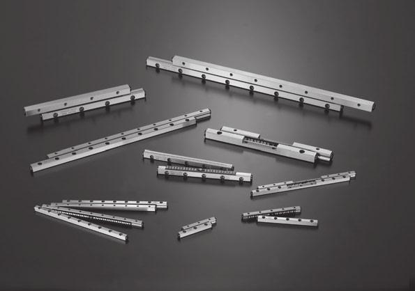
2 eaures of Crossed Roller ay Series wide variey of series producs includin cae misalinmen prevenion mechanism are available! eaures of Crossed Roller ay Crossed Roller ay is a linear moion rollin uide incorporain a roller cae beween wo ways whose wo V-shaped surfaces are used as rack roove. rranemen of cylindrical rollers by orhoonalizin hem alernaely allows receivin of loads in any direcion and execues exremely hih-accuracy and smooh linear moion. Crossed Roller ay CR CR ni-creep Cae Crossed Roller ay CRG ni-creep Cae Crossed Roller ay Uni CRUG ni-creep Cae Crossed Roller ay CRG ni-creep Cae Crossed Roller ay CRG is a produc wih a cae creep proof funcion usin a rack and pinion mechanism oriinaed from he Crossed Roller ay CR feaurin smooh linear moion wih super hih accuracy. CRG is hih load capaciy ype of CRG, which has achieved realy increased load rain by redesinin of raceway of CRG. Buil-in rack & pinion ype Solves cae creep issue!! ni-creep Cae Crossed Roller ay Uni CRUG is a produc wih a cae creep proof funcion-provided Crossed Roller ay CRG mouned ino a round-finished riid able and bed. CRUG srucure 5 Rack Crossed Roller ay Uni CRU Pinion ear Oriinal rack & pinion srucure Cylindrical rollers Cae Rack Cylindrical rollers Cae Rack Roller cae Rack Pinion ear Roller cae eaures of Buil-in Rack & Pinion Type Solves Cae Creep Issue Perfec soluion for cae creep issues by a buil-in rack and pinion mechanism as an oriinal desin. reedom in ounin This series is reliable for applicaions such as verical axis where Crossed Roller ay may have chances of cae creep. ih-speed and ih-tac Operaion ny correcive operaion for cae creep is no necessary even for hih velociy operaion. Savin nery o remedy moion of cae is necessary even in lon erm operaion. asy Replacemen Since hey have he same exernal dimensions o hose of he exisin Crossed Roller ay and Crossed Roller ay Uni, exisin Crossed Roller ay and Crossed Roller ay Uni can be replaced Pinion ear wihou any mounin dimensions modificaion. Durabiliy es Tes condiions odel number CRG3 Tes mehod Vibraion es machine Resul Condiion Toal cycles Inerchaneable in ounin Dimensions dopion of oriinal srucure of arranin a rack inside he way keeps he same mounin dimensions as convenional Crossed Roller ay CR. * The mounin dimensions of CRG1 and CR1 are differen. Improved Runnin ccuracy xremely hih runnin accuracy can be achieved wihou run deflecion by recirculain ype linear moion rollin uide. CRG CRG Posure aximum velociy cceleraion umber of cycle Sroke lenh ass of movin par Verical 827 mm/s 15 G 31 z 8 mm ,000,000 cycles Smooh and xremely-ih ccurae Operaion Combinaion of precisely finished raceways and non-recirculain ype linear moion rollin uide wih super hih precision rollers provides superbly smooh moion wih very hih accuracy. Rack o cae creep even under hih-ac operaion in verical axis! o cae creep nor maerial damae in any componen is found. CRUG Rack Pinion ear Rack Pinion ear CR CRU CRG Suiable for icro-eedin Improvemen of precision posiionin accuracy and superior correspondin feaure o micro-feedin command can be expeced because of he linear moion wihou sick-slip by exremely small fricional resisance. 1=0.102kf=0.2248lbs. Vibraion machine 6


3 ni-creep Cae Crossed Roller ay CRG Idenificaion umber and Specificaion xample of an idenificaion number The specificaions of CRG series, CRG series, and CR series are indicaed by he idenificaion number. Indicae he idenificaion number, consisin of a model code, a dimension, a par code, a maerial code, a classificaion symbol, and any supplemenal codes for each specificaion o apply. Pinion ear CRG series CRG series CRG SP /B Rack CR series Sandard ype CR C20 S SP /U ni-creep Cae Crossed Roller ay CRG ay CR C36 S SP /U odule ype CR C20 SP /U CR C20 SP /U ay Cylindrical rollers cae Roller cae 1 odel odel code Pae 9 Rack Crossed Roller ay CR/CR nd screw Size ay lenh umber of cylindrical rollers Dimensions Pae 9 Par code Pae 10 Poins 5 aerial ype aerial code Pae 10 Superior load balance 1 This uni has a roller cae wih cylindrical rollers alernaely orhoonalized beween wo ways whose wo V-shaped surfaces are used as rack roove, which allows receivin of loads in any direcion. 2 Solves cae creep problem CRG and CRG unis, which have oriinally-desined rack and pinion mechanism buil-in, solve he cae creep issue and suppor hih-speed & hih-ac operaion and verical axis applicaion. 4 Sandard ype and module ype There are wo ypes in he CR: one is sandard ype of usin four ways and wo roller caes in combinaion as a se and he oher is module ype of inerain wo inernal ways in a sinle srucure. 5 asy mounin The mounin holes of he way are provided wih borin and female hread, so ha he mounin srucure is no resriced.the module ype wih wo inernal ways ineraed in a sinle srucure is simple in mounin srucure, hus producin hih accuracy linear moion. 6 ccuracy class Classificaion symbol 7 Special specificaion Supplemenal code Pae 11 Pae 11 oe: One se of he CR, CRG, and CRG... series consiss of a combinaion of four ways and wo roller caes. 3 ih load capaciy ype CRG CRG has achieved realy increased load rain by redesinin of raceway of CRG, hereby downsizin he machine and equipmen and prolonin heir lifeime. Sainless seels superior in corrosion resisance are lised on lineup. 6Producs made of sainless seel are hihly resisance o corrosion, so ha hey are suiable for applicaions where rus prevenion oil is no preferred, such as in a cleanroom environmen. 7 1=0.102kf=0.2248lbs. 8
4 Idenificaion umber and Specificaion 1 2 odel Size ni-creep Cae Crossed Roller ay CRG series ni-creep Cae Crossed Roller ay CRG series Crossed Roller ay CR series or applicable models and sizes, see i. 1. Sandard ype odule ype odel Size CRG CRG CR CR 1, 2, 3, 4, 6, 9, 12, 15, 18, 24 or applicable models and sizes, see Table 1. Table 1 odels and Sizes of CRG series, CRG series, and CR series Series aerial odel CRG ih carbon seel made Size CRG ay lenh umber of Cylindrical Rollers aerial Type 3 ay lenh Specifyin he combinaion of differen way lenhs Combinaion of sandard ype This combinaion consiss of wo shor ways, wo lon ways, and wo roller caes, as a se. In his case, make sure o specify he number of rollers o be incorporaed in he roller caes. (or calculaion of incorporaed rollers, see he Selecion of CR Series on pae -17.) xample CR C24 Combinaion of module ype The way lenh is indicaed in mm. The CR series can be combined wih a way of differen lenh. or deails of way lenh, see he dimension ables on paes -27 o -52. This combinaion consiss of one lon cener way, wo shor ways, and wo roller caes, as a se. In his case, make sure o specify he number of rollers o be incorporaed in he roller caes. (or calculaion of incorporaed rollers, see he Selecion of CR Series on pae -17.) xample CR C20 CRG ih carbon seel made CRG The number of cylindrical rollers o be incorporaed in a uni: 24 enh of lon way: 400 mm The number of cylindrical rollers o be incorporaed in a uni: 20 enh of shor ouside way: 150 mm Sandard ype ih carbon seel made CR enh of shor way: 300 mm enh of lon cener way: 200 mm CR Sainless seel made CRS odule ype ih carbon seel made CR 4 umber of cylindrical rollers o symbol C This represens he number of cylindrical rollers incorporaed ino a CR series cae. If no direced, he number of cylindrical rollers indicaed in he dimension able shall be incorporaed in a roller cae. 5 aerial ype ih carbon seel made Sainless seel made o symbol S or applicable models and sizes, see i =0.102kf=0.2248lbs. 10
5 ccuracy Class Special Specificaion Special Specificaion 6 ccuracy class Sandard Super precision o symbol SP or parallelism of he raceway o reference mounin surface and he olerance of he parallelism of wo raceways of CR, see i. 1. Special mounin screw /B Preload adjusin-side way can be moved by adjusin he preload. llowance for movemen is required beween a way fixin screw and mounin hole, bu special mounin screws are provided for he cases where enouh allowance is no provided or a fixin screw should be mouned from he way side as shown in i. 2. This special mounin screw can also be used for he case where he mounin hole for mounin he fixed-side way and posiionin accuracy of female hread are no enouh. This special mounin screw is hih carbon seel-made only. B B Table 4 Dimensions of special mounin screw S CRG, CRG, CR CR D d 10 Parallelism μm SP ay lenh mm i. 1 ccuracy Bol size uni: mm Size Bol size d D S i. 2 ounin by special mounin screw 7 Special specificaion B,, S, SB, U or applicable special specificaions, see Table 2. or combinaion of muliple special specificaions, see Table 3. or deails of special specificaions, see paes -11 o -14. ih riidiy roller cae / Table 2 pplicaion of special specificaions Special specificaion Supplemenal code Size Special mounin screw /B ih riidiy roller cae 1 2 / nd sopper S 2 /S nd sopper SB 2 /SB iper seal 2 /U oes 1 o applicable o module ype. 2 o applicable o CRG series and CRG series. The cae is chaned ino a hih riidiy copper alloy-made cae desined o sui verical axis applicaion. This cae has a srucure o preven a roller from droppin off in one-side direcion. or usin a hih riidiy roller cae for verical axis applicaion, i is recommended o use he cae in combinaion wih end sopper SB. Table 3 Combinaion of special specificaions S SB U B S SB Remarks 1. The combinaion of "" shown in he able is no available. 2. hen usin muliple ypes for combinaion, please indicae by arranin he symbols in alphabeical order. 11 1=0.102kf=0.2248lbs. 12
6 Special Specificaion Special Specificaion nd sopper S /S hen he sroke frequency is hih and cae creep may be caused by he vibraion and non-uniformly varyin load, he end screw is chaned ino end sopper S. or he series of size 1, an end sopper S accordin o end sopper S is included as sandard. iper seal /U In order o preven forein subsances from enerin ino a raceway, he wiper seal is chaned ino he one wih a funcion of end sopper SB. The wiper seal canno be mouned on all way ends. Sandard mounin posiions are shown in i. 4. The mounin posiions can be chaned by loosenin he screw. Table 5 Dimensions of end sopper S 1 Table 7 Dimensions of wiper seal uni: mm Size 1 2 Size uni: mm Size 1 2 Size i. 4 rranemen of wiper seal nd sopper SB /SB hen usin a hih riidiy roller cae for verical axis applicaion, he end screw is chaned ino end sopper SB o reulae he cae sroke a he end. The end sopper SB canno be mouned on all way ends. Sandard mounin posiions are shown in i. 3. The mounin posiions can be chaned by loosenin he screw. Table 6 Dimensions of end sopper SB 1 2 uni: mm Size 1 2 Size i. 3 rranemen of end sopper SB 13 1=0.102kf=0.2248lbs. 14
7 oad Rain and llowable oad Basic dynamic load rain C, basic saic load rain C 0, and allowable load of he CRG series and CRG series show values for downward loads in case of parallel arranemen of four ways and wo pairs of roller caes as one se. (Refer o i. 5) In addiion, he upward and laeral load rain is he same as downward load rain. or he CR series, since he number of cylindrical rollers ha share load of each direcion varies, he load rain for each load direcion and allowable load mus be obained. In addiion, basic dynamic load rain C U, basic saic load rain C 0U, and allowable load U in he dimension able show values per cylindrical roller. Basic dynamic load rain C, basic saic load rain C 0, and allowable load of he CR series are obained based on he equaion indicaed in Table 8.1 and Table 8.2. or more informaion on he definiion of load rain and calculaed load, see pae -3. C, C0, i. 5 Direcion of load rain of he CRG series and CRG series Table 8.2 Calculain formula of load rain and allowable load of module ype CR series oad direcion Upward and downward load 1/2 of he loa/2 of he load oad aeral load Basic dynamic load rain C C r {( Z 1/ ) 2p } ( Z 2 ) 3/4 2 7/9 C 7 U C a {( Z 2 1 ) 2p } 1/36( Z 2 ) 3/4 2 7/9 C 10 U Basic saic load rain C 0 C 0r 2 ( Z 2 )C 0U 8 C 0a 2 ( Z 2 )C 0U 11 llowable load r 2 ( Z 2 ) U 9 a 2 ( Z 2 ) U 12 oad oad llowable load llowable load refers o load of smooh rollin moion on conac surface o which maximum conac sress is applied and he sum of whose elasic deformaion of rollin elemens and raceway is small. Therefore, use applied load wihin he allowable load rane if very smooh rollin moion and hih accuracy are required. Table 8.1 Calculain formula of load rain and allowable load of sandard ype CR series Upward and downward load 1 oad aeral load Code descripion C r Basic dynamic load rain in case upward and downward load is applied C a Basic dynamic load rain in case laeral load is applied C 0r Basic saic load rain in case upward and downward load is applied C 0a Basic saic load rain in case laeral load is applied r llowable load in case upward and downward load is applied a llowable load in case laeral load is applied The number of cylindrical rollers incorporaed in a roller cae Z (omi he fiures afer he decimal fracions for Z 2 ) p Iner-pich dimensions of cylindrical rollers mm C U Basic dynamic load rain per cylindrical roller C 0U Basic saic load rain per cylindrical roller U llowable load per cylindrical roller oad direcion oad oad oad Basic dynamic load rain C C r {( Z 2 1 ) 2p } 1/36( Z 2 ) 3/4 C U 1 C a {( Z 2 1 ) 2p } 1/36( Z 2 ) 3/4 2 7/9 C U 4 Basic saic load rain C 0 C 0r ( Z 2 )C 0U 2 C 0a 2 ( Z 2 )C 0U 5 llowable load r ( Z 2 ) U 3 a 2 ( Z 2 ) U 6 Code descripion C r Basic dynamic load rain in case upward and downward load is applied C a Basic dynamic load rain in case laeral load is applied C 0r Basic saic load rain in case upward and downward load is applied C 0a Basic saic load rain in case laeral load is applied r llowable load in case upward and downward load is applied a llowable load in case laeral load is applied The number of cylindrical rollers incorporaed in a roller cae Z (omi he fiures afer he decimal fracions for Z 2 ) p Iner-pich dimensions of cylindrical rollers mm C U Basic dynamic load rain per cylindrical roller C 0U Basic saic load rain per cylindrical roller U llowable load per cylindrical roller oe 1 : In case of parallel arranemen in his load direcion, calculaion mus be performed based on he equaions 7, 8, and 9in Table =0.102kf=0.2248lbs. 16
8 Selecion of CR Series or selecion of CR series specificaions, sroke lenh and he number of cylindrical rollers, as well as accuracy, load rain and allowable load, mus be deermined. Sroke lenh and he number of cylindrical rollers Sroke lenh of he CR series affecs he way lenh and he number of cylindrical rollers. Therefore, selec specificaions by followin he procedure below akin ino accoun he sroke lenh used and applied load. Calculaion of cae lenh and he number of rollers ih he way lenh and maximum sroke lenh deermined, he allowable lenh for cae can be calculaed. Calculaion mehod of he cae lenh varies dependin on specificaions of end screws and end sopper fied o he way end. (1) ih sandard end screws and end sopper S (excludin Size 1 series) The dimensions beween rollers a boh ends is obained from he followin equaion by usin a value obained by subracin a half of he maximum sroke lenh from he way lenh. (2) or Size 1 series The sroke lenh is reulaed by cae and end sopper and he cae lenh is obained by he followin equaion. R S 1 2 here R: llowable cae lenh mm : ay lenh mm S 1 : aximum sroke lenh mm S 1 (17) Calculaion examples orm of use CR 6 pplied load P 7000 Sroke lenh S 195 mm Selec specificaions for parallel use of Crossed Roller ay under he above condiions (refer o i. 26 in pae -23). Calculaion of way lenh The way lenh is calculaed from he equaion (13). Calculaion of way lenh The way lenh, which should be 1.5 imes loner han he sroke lenh used, is obained from he equaion below. 1.5S (13) here : ay lenh mm S: Sroke lenh used mm S R S 1 2 (15) here R : llowable dimensions beween rollers a boh ends mm : ay lenh mm S 1 : aximum sroke lenh mm S 1 /2 S 1 S 1 /2 R The number of rollers o be incorporaed in a roller cae is obained by he followin equaion. S 1 /2 1.5S Therefore, selec = 300 mm based on he sandard lenh in he dimension able. Calculaion of maximum sroke lenh The maximum sroke lenh S 1 is calculaed from he equaion 14. S 1 1 S S Calculaion of maximum sroke lenh Ideally he sroke lenh used should be less han 80% of he maximum sroke lenh, which is obained from he equaion below. S S (14) here S 1 : aximum sroke lenh mm S : Sroke lenh used mm The number of rollers o be incorporaed in a roller cae is obained by he followin equaion. Z RD p R 1 (16) here Z : umber of cylindrical rollers (fiures afer he decimal fracions are omied) R : llowed dimensions beween rollers a boh ends mm D : Diameer of cylindrical rollers (refer o he dimension able) mm p : Iner-pich dimensions of cylindrical rollers (refer o he dimension able) mm S 1 /2 Z R2e 1 p (18) here Z : umber of cylindrical rollers (fiures afer he decimal fracions are omied) R: llowable cae lenh mm e : nd dimension of cae (refer o he dimension able) mm p : Iner-pich dimensions of cylindrical rollers (refer o he dimension able) mm (3) or end sopper SB and wiper seal The sroke lenh is reulaed by cae and end sopper or wiper seal and he cae lenh is obained by he followin equaion. R= 2 S 1 (19) here R : llowable cae lenh mm : ay lenh mm S 1 : aximum sroke lenh mm 2 : Thickness of end sopper SB or wiper seal mm (See Table 6 in pae -13, and Table 7 in pae -14) llowable dimensions beween rollers a boh ends R is calculaed from he equaion (15). R S Calculaion of he number of rollers The number of cylindrical rollers Z is calculaed from he equaion (16). owever, D and p in his form are D = 6 mmp = 9 mm accordin o he dimension able. Z RD p 9 Therefore, i should be Z = 20 by omiin fiures afer he decimal fracions. Calculaion of allowable load llowable load in parallel arranemen is calculaed from equaion (9) described in Table 8.2 in pae -16. owever, allowable load per cylindrical roller U is U = 769 accordin o he dimension able. 2( Z 2 ) U 2( 20 2 ) Therefore, allowable load is larer han applied load P = hen allowable load becomes smaller han applied load, i is necessary o increase he number of cylindrical rollers by exendin way lenh, or increase he cylindrical roller diameer. R S 1 2 Deerminaion of specificaions Specificaions obained in accordance wih he above is CR6-300 and he number of cylindrical rollers is 20. The number of rollers o be incorporaed in a roller cae is obained by he equaion (18) as wih he Size 1 series. 17 1=0.102kf=0.2248lbs. 18
9 ubricaion Precauion for Use Grease is no pre-packed in he CRG series, CRG series and CR series, so please perform adequae lubricaion as needed. Boh of oil lubricaion and rease lubricaion are available in he CRG series, CRG series and CR series. Generally, oil lubricaion should be seleced for hih speed or low fricional resisance, and rease lubricaion for low speed. or rease lubricaion, use of hih-qualiy lihium-soap base rease is recommended. or lih load and low speed, apply rease or oil o raceway, rack and pinion ear firs and hen reapply accordinly. owever, he srucure as indicaed in he i. 6 allows for easy reapplicaion. In addiion, since he clearance beween ways is small for CRG series, apply rease or oil direcly o raceway for re-reasin. i. 6 xample of lubricaion sysem Dus Proecion Since he CRG series, CRG series and CR series are finished wih hih accuracy, harmful forein subsances such as dus and paricles enerin ino he bearin will cause low life or impaired accuracy. To preven harmful forein subsances such as dus, paricles and waer from ouside from enerin, i is recommended o aach non-conac ype labyrinh seal as indicaed in i. 7, or conac ype wiper seal as indicaed in he i. 8 o boh sides. andlin s he CRG series, CRG series and CR series are desined hihly precisely, ake exra care for handlin. pinion ear and cylindrical roller are incorporaed wih he cae for he CRG series and CRG series. hen he cae is dropped or handled rouhly, he pinion ear and cylindrical roller may come off. specially for CRG, rabbin he cylindrical roller may ake i off, so be sure o hold he cae body for handlin. In addiion, do no cu off he cae as doin so may cause pinion ear comin off and breakae of ear join secion. rack is incorporaed wih he way for he CRG series and CRG series. In operaion, ake noe ha he rack may come off when he end screw is removed. Thouh he cae for he CR series may cu off o necessary lenh, handle i wih care no o deform i when cuin. ccuracy of mounin par xamples of ypical mounin surface processin are shown in i. 9.1 and i General processin accuracy of mounin surface is accordin o Table 9. owever, care should be exercised as mounin surface accuracy direcly affecs runnin accuracy. specially when hih runnin accuracy is required, he processin accuracy hiher han ha indicaed in Table 9 is required. B C i. 9.1 xample of processin of CRG, CRG and CR mounin surface C B Table 9 ccuracy of mounin par ccuracy of surface ccuracy of B and C surfaces Direcly affecs runnin accuracy. or he flaness of wo mounin surfaces on able and bed sides, allowable value approximae o he parallelism indicaed in i. 1 in pae -11 is recommended. laness ffecs preload (refer o Preload adjusmen mechanism). 11llowable value approximae o he parallelism indicaed in i. 1 in pae -11 is recommended. Squareness ffecs riidiy in preload direcion of he mounin par of he CRG series, CRG series and CR series. Process o sufficienly hih accuracy. of mounin par or he opposie corner of he main reference mounin, i is recommended o have relieved fille as indicaed in i. 10. In addiion, a clearance of 0.5 mm or hiher should be made beween he way and he main member maerial. 0.5 or hiher i. 10 of mounin par Preload adjusmen mechanism or use wih preload, use he preload adjusin screw as indicaed in i. 11 as a eneral way. Preload adjusin screw nominal dimensions and mounin posiion should be in accordance wih he way fixin bol dimensions and posiion. Press he cener of he way dimensions. Preload amoun varies dependin on operaional condiions of your machine and device. owever, as excessive preload may lead o shor life and damae on he raceway, i is ypically ideal o adjus o zero clearance or slih preload sae. hen accuracy and riidiy are required, use a push plae or apered jib as indicaed in i. 12 and i. 13, respecively. 0.5 or hiher i. 12 xample of push plae i. 13 xample of apered jib Operain emperaure s synheic resin componens are used for he CRG series and CRG series, he maximum operain emperaure is 120 C, while i should be lower han 100 C for coninuous use. hen i exceeds 100 C, conac. s synheic resin componens are no used for he CR series, i may be used a hih emperaure. owever, when i exceeds 100 C, conac. aximum velociy Operain velociy should be lower han 50 m/min for he CRG series and CRG series, and lower han 30 m/ min for he CR series. Tihenin orque for fixin screw Typical ihenin orque for mounin of he CRG series, CRG series and CR series is indicaed in Table 10. hen vibraion and shock are lare or momen load is applied, i is recommended o fix by usin he orque 1.3 imes larer han ha indicaed in he able. In addiion, when hih runnin accuracy is required wih no vibraion and shock, i may be fixed by usin orque smaller han ha indicaed in he able, however, i is recommended o use adhesive aen o fasen he screw, or o use sop bols. 19 i. 7 xample of labyrinh seal i. 8 xample of wiper seal i. 9.2 xample of processin of CR mounin surface i. 11 xample of ypical preload adjusmen Table 10 Tihenin orque for fixin screw Tihenin orque Remark: Bol size m hen fixin screws used on he able side and bed side are no idenical, fasen hem all o he smaller ihenin orque =0.102kf=0.2248lbs. 20
10 ounin ounin of CRG series and CRG series Typical mounin srucure is shown in i. 14. or mounin a his poin, enerally follow he procedure below. ixin-side way Bed-side way Bed-side way Preload-adjusmenside way ounin of bed-side way Properly alin he way wih mounin surface and emporarily ihen fixin screws evenly o he ihenin orque. hile makin he way sickin o B surface (refer o i. 15) ih, fully ihen he screws o he specified orque. hen hih runnin accuracy is required, fully and evenly ihen hem o he specified orque while checkin he parallelism of he raceway alon he full lenh of he way. Typical ihenin orque for fixin screw is accordin o Table 10 in pae -20. Posiion he able-side way in he sroke end posiion. (Refer o i. 19) ae he pinion ear a he cener of he cae and he rack of he able-side way. Temporarily ihen he able fixin screws. (Refer o i. 22) Preload adjusin screw i. 14 ounin example of CRG and CRG Preparaion for mounin Producs are packed by se (4 ways an pairs of roller caes). Be careful no o mix wih oher ses. Remove end screws and end sopper, clean up each par wih clean wash fluid and hen apply rus prevenion and lubricaion oil. Cleanup of mounin surface Remove burrs and blemishes on he machine mounin surface wih an oil-sone, ec. Be careful abou corner roove on he mounin surface, oo. ipe off dus and dir wih clean cloh and apply rus prevenion and lubricaion oil lihly. i. 16 ccuracy of way mounin i. 19 Posiion he able-side way approximaely in he sroke cener posiion. (Refer o i. 20) i. 22 ully sroke he able sofly and check ha i is wihin he sroke rane used and cylindrical rollers on boh ends of he cae do no conac wih end screws of he way. If hey make conac, ake he procedure aain. (Refer o i. 23) Corner roove Corner roove ounin surface C ounin surface ounin surface i. 17 i. 20 ounin surface B ounin surface B ounin surface ounin surface Corner roove Operaion of able and bed Posiion he roller caes a he sroke end posiions of he bed-side way. (Refer o i. 18) ae he pinion ear a he cener of he cae and he rack of he way. his poin, be careful no o deform he cae. Posiion he able while holdin he way o preven i from movin. (Refer o i. 21) i. 23 i. 15 ounin surface i. 21 i =0.102kf=0.2248lbs. 22
11 ounin Preload adjusmen Preload adjusmen is performed wih fixin screws of he able-side way ihened emporarily. Preload adjusmen is sared from he preload adjusin screw a he cener of way lenh and hen boh ends in urn. hile measurin he clearance on he able sides, ihen he preload adjusin screws subsequenly unil deflecion of he dial aue sops. easure he ihenin orque for preload adjusin screws a his poin. hen adjusin preload adjusin screw near eiher end, sroke he able sofly and check ha he cylindrical roller is on he preload adjusin screw secion. fer he above procedure, he clearance becomes zero or in slih preload sae, bu preload is sill no adjused evenly. ih he same procedure aain, re-adjus all he preload adjusin screws evenly o he orque previously measured. i. 24 xample of preload adjusmen mehod ull ihenin of preload-adjusmen-side way ixin screws are lihly ihened o even orque. s wih preload adjusin screws, emporarily fix hem o orque similar o he specified orque in urn from he way cener o boh ends. hen ihenin fixin screws near eiher end, sroke he able sofly and check ha he cylindrical roller is on fixin screw secion. inally wih he same procedure, fully ihen all he fixin screws evenly o he specified orque. Check afer assembly ully sroke he able sofly and check ha runnin is smooh wihou abnormal noise. easure he able upper and side surfaces wih dial aue or he like and check he runnin accuracy. ounin of sandard ype CR series Typical mounin srucure is shown in i. 26. or mounin a his poin, enerally follow he procedure below. ixin-side way Bed-side way Bed-side way i. 26 ounin example of sandard ype CR series Preparaion for mounin Producs are packed by se (4 ways an pairs of roller caes). Be careful no o mix wih oher ses. Remove end screws and end sopper, clean up each par wih clean wash fluid and hen apply rus prevenion and lubricaion oil. Cleanup of mounin surface Remove burrs and blemishes on he machine mounin surface wih an oil-sone, ec. Be careful abou corner roove on he mounin surface, oo. ipe off dus and dir wih clean cloh and apply rus prevenion and lubricaion oil lihly. Corner roove Corner roove i. 27 ounin surface Preload-adjusmenside way ounin surface C ounin surface ounin surface ounin surface B ounin surface Corner roove ounin surface B ounin surface Preload adjusin screw ounin of bed-side way Properly alin he way wih mounin surface and emporarily ihen fixin screws evenly o he ihenin orque. hile makin he way sickin o B surface (refer o i. 27) ih, fully ihen he screws o he specified orque. hen hih runnin accuracy is required, fully and evenly ihen hem o he specified orque while checkin he parallelism of he raceway alon he full lenh of he way. Typical ihenin orque for fixin screw is accordin o Table 10 in pae -20. i. 28 ccuracy of way mounin ounin of able-side way Properly alin he fixin-side way wih mounin surface and emporarily ihen fixin screws evenly o he ihenin orque. hile makin he fixin-side way sickin o C surface ih, fully ihen he screws o he specified orque. Se back he preload adjusin screws in advance, make he preload-adjusin-side way sickin o he mounin surface, and hen emporarily ihen fixin screws lihly o he even orque. C surface ixin-side way i. 29 ounin of able-side way Preload-adjusmen-side way Preload adjusin screw Operaion of able and bed ake alinmen of he posiion in heih and cross direcion so ha he roller cae can be insered beween he able-side way and bed-side way. Carefully inser he roller cae and assembly i a approximae cener of he way lenh. his poin, be careful no o deform he cae. oun end screws and end sopper of each way. Push he enire able aains he preload adjusin screws and ihen he preload adjusin screws o make emporary adjusmen unil he clearance beween ways becomes zero. ully sroke he able sofly and correc he roller cae posiion o he cener. i. 30 Posiion alinmen before operaion Preload adjusmen Preload adjusmen is performed wih fixin screws of he preload-adjusin-side way ihened emporarily. Preload adjusmen is sared from he preload adjusin screw a he cener of way lenh and hen boh ends in urn. hile measurin he clearance on he able sides, ihen he preload adjusin screws subsequenly unil deflecion of he dial aue sops. easure he ihenin orque for preload adjusin screws a his poin. hen adjusin preload adjusin screw near eiher end, sroke he able sofly and check ha he cylindrical roller is on he preload adjusin screw secion. fer he above procedure, he clearance becomes zero or in slih preload sae, bu preload is sill no adjused evenly. ih he same procedure aain, re-adjus all he preload adjusin screws evenly o he orque previously measured. i. 31 xample of preload adjusmen mehod i. 25 ccuracy check afer assembly 23 1=0.102kf=0.2248lbs. 24
12 ounin ull ihenin of preload-adjusmen-side way ixin screws are lihly ihened o even orque. s wih preload adjusin screws, emporarily fix hem o orque similar o he specified orque in urn from he way cener o boh ends. hen ihenin fixin screws near eiher end, sroke he able sofly and check ha he cylindrical roller is on fixin screw secion. inally wih he same procedure, fully ihen all he fixin screws evenly o he specified orque. Check afer assembly ully sroke he able sofly and check ha runnin is smooh wihou abnormal noise. easure he able upper and side surfaces wih dial aue or he like and check he runnin accuracy. ounin of module ype CR series Typical mounin srucure of CR is shown in i. 33. or mounin a his poin, enerally follow he procedure below. ixin-side way Cener way Preload-adjusmenside way Preload adjusin screw Processin of dowel pin hole hen dowel pins are used, machine holes on he bed in alinmen wih dowel pin holes near eiher end of he cener way. Dowel pin hole of he cener way is finished for 7. inish bed holes in he same way. Diameer and is allowance of dowel pin hole of he cener way vary dependin on he dimension able. liminae cuin chips and clean up aain as necessary. hen machines for mounin of he cener way are lare, clean hem up wih he cener way removed and hen reassemble. oad he dowel pins and check he parallelism of he reference surface of he runnin parallelism and he raceway of he cener way aain. ain marks module ype CR series CR has main marks o ensure he bes runnin accuracy afer mounin based on he parallelism measuremen resul of reference mounin surface and raceway. hen assemblin he ways, alin he main marks of ways wih he same end side as indicaed in i. 36. ain mark Cener way i. 33 xample of mounin of CR ain mark i. 32 ccuracy check afer assembly Preparaion for mounin Crossed Roller ay CR is packed by se (1 cener way, 2 ways an pairs of roller caes). Be careful no o mix wih oher ses. Remove end screws and end sopper, clean up each par wih clean wash fluid and hen apply rus prevenion and lubricaion oil. i. 36 ain marks of CR Cleanup of mounin surface Remove burrs and blemishes on he machine mounin surface wih an oil-sone, ec. Be careful abou corner roove on he mounin surface, oo. ipe off dus and dir wih clean cloh and apply rus prevenion and lubricaion oil lihly. i. 35 achinin of dowel pin hole ounin of able-side way ollow he mounin of sandard ype CR series. ounin of cener way Rouhly alin he cener way o he mounin surface and lihly fix i wih fixin screws. hile measurin mounin parallelism of he cener way and raceway o he reference surface of runnin parallelism for posiion correcion, emporarily ihen he fixin screws o he even ihenin orque. venly ihen all he fixin screws o he specified ihenin orque. Operaion of able and bed ollow he mounin of sandard ype CR series. Preload adjusmen ollow he mounin of sandard ype CR series. ull ihenin of preload-adjusmen-side way ollow he mounin of sandard ype CR series. Check afer assembly ollow he mounin of sandard ype CR series. Runnin parallelism reference surface i. 34 ounin accuracy check for cener way 25 1=0.102kf=0.2248lbs. 26
13 ni-creep Cae Crossed Roller ay CRG Size n R e p Z umber of rollers D h Idenificaion number CRG ass (Ref.) ominal dimensions mm aximum sroke lenh ay 1 Roller cae 2 Boundary dimensions Dimension of roller cae ounin dimensions n D R Z p e h mm CRG Basic dynamic load rain C Basic saic load rain C 0 llowable load CRG CRG CRG CRG CRG CRG CRG CRG CRG CRG CRG CRG CRG CRG CRG CRG oes 1 The value shows he mass of a piece of way. 2 The value shows he mass of a roller cae. This is he value when a combinaion of four ways and wo roller caes is used in parallel arranemen. 27 1=0.102kf=0.2248lbs. 28
14 ni-creep Cae Crossed Roller ay CRG Size n R e p Z umber of rollers D h Idenificaion number CRG ass (Ref.) ominal dimensions mm aximum sroke lenh ay 1 Roller cae 2 Boundary dimensions Dimension of roller cae ounin dimensions n D R Z p e h mm CRG Basic dynamic load rain C Basic saic load rain C 0 llowable load CRG CRG CRG CRG CRG CRG CRG CRG CRG CRG CRG oes 1 The value shows he mass of a piece of way. 2 The value shows he mass of a roller cae. This is he value when a combinaion of four ways and wo roller caes is used in parallel arranemen. 29 1=0.102kf=0.2248lbs. 30
15 ni-creep Cae Crossed Roller ay CRG Size n n R e p Z (umber of rollers) D h CRG 1 CRG 31 Idenificaion number CRG ass (Ref.) ominal dimensions mm aximum sroke lenh ay 1 Roller cae 2 Boundary dimensions Dimension of roller cae ounin dimensions n D R Z p e h mm CRG CRG Basic dynamic load rain C Basic saic load rain C 0 llowable load CRG CRG CRG CRG CRG CRG CRG CRG CRG CRG CRG CRG CRG CRG CRG CRG CRG CRG CRG CRG CRG CRG CRG CRG CRG CRG CRG CRG CRG oes 1 The value shows he mass of a piece of way. 2 The value shows he mass of a roller cae. This is he value when a combinaion of four ways and wo roller caes is used in parallel arranemen. 1=0.102kf=0.2248lbs. 32
16 Crossed Roller ay Sandard ype Size CR CRS n e p R Z umber of rollers D h Idenificaion number CR 1-20 ay 1 k/m ass (Ref.) ominal dimensions mm Basic dynamic Boundary dimensions Dimension of roller cae ounin dimensions load rain Roller cae 2 CR 1-20 S CR 1-30 CR 1-30 S CR 1-40 CR 1-40 S CR 1-50 CR 1-50 S CR 1-60 CR 1-60 S CR 1-70 CR 1-70 S CR 1-80 CR 1-80 S oes 1 The value shows he mass per meer of a way. 2 The value shows he mass of a roller cae wih en cylindrical rollers. The value shows he load of a cylindrical roller. n D R Z p e h C U Basic saic load rain C 0U llowable load U 33 1=0.102kf=0.2248lbs. 34
17 Crossed Roller ay Sandard ype Size CR CRS n e p R Z umber of rollers D h Idenificaion number CR 2-30 ass (Ref.) ominal dimensions mm Basic dynamic Boundary dimensions Dimension of roller cae ounin dimensions load rain ay 1 Roller cae 2 C 3 U n D R Z p e h k/m CR 2-30 S CR 2-45 CR 2-45 S CR 2-60 CR 2-60 S CR 2-75 CR 2-75 S CR 2-90 CR 2-90 S CR CR S CR CR S CR CR S CR CR S CR CR S CR CR S oes 1 The value shows he mass per meer of a way. 2 The value shows he mass of a roller cae wih en cylindrical rollers. The value shows he load of a cylindrical roller Basic saic load rain C 0U llowable load U 35 1=0.102kf=0.2248lbs. 36
18 Crossed Roller ay Sandard ype Size CR CRS n e p R Z umber of rollers D h Idenificaion number CR 3-50 ay 1 k/m ass (Ref.) ominal dimensions mm Basic dynamic Boundary dimensions Dimension of roller cae ounin dimensions load rain Roller cae 2 CR 3-50 S CR 3-75 CR 3-75 S CR CR S CR CR S CR CR S CR CR S CR CR S CR CR S CR CR S CR CR S CR CR S oes 1 The value shows he mass per meer of a way. 2 The value shows he mass of a roller cae wih en cylindrical rollers. The value shows he load of a cylindrical roller. n D R Z p e h C U Basic saic load rain C 0U llowable load U 37 1=0.102kf=0.2248lbs. 38
19 Crossed Roller ay Sandard ype Size CR CRS n e p R Z umber of rollers D h Idenificaion number CR 4-80 ay 1 k/m ass (Ref.) ominal dimensions mm Basic dynamic Boundary dimensions Dimension of roller cae ounin dimensions load rain Roller cae 2 CR 4-80 S CR CR S CR CR S CR CR S CR CR S CR CR S CR CR S CR CR S CR CR S CR CR S CR CR S oes 1 The value shows he mass per meer of a way. 2 The value shows he mass of a roller cae wih en cylindrical rollers. The value shows he load of a cylindrical roller. n D R Z p e h C U Basic saic load rain C 0U llowable load U 39 1=0.102kf=0.2248lbs. 40
20 Crossed Roller ay Sandard ype Size CR CRS n e p R Z umber of rollers D h Idenificaion number CR ay 1 k/m ass (Ref.) ominal dimensions mm Basic dynamic Boundary dimensions Dimension of roller cae ounin dimensions load rain Roller cae 2 CR S CR CR S CR CR S CR CR S CR CR S CR CR S CR CR S CR CR S CR CR S CR CR S CR CR S oes 1 The value shows he mass per meer of a way. 2 The value shows he mass of a roller cae wih en cylindrical rollers. The value shows he load of a cylindrical roller. n D R Z p e h C U Basic saic load rain C 0U llowable load U 41 1=0.102kf=0.2248lbs. 42
21 Crossed Roller ay Sandard ype CR Size n e p R Z umber of rollers D h Idenificaion number CR ay 1 k/m ass (Ref.) ominal dimensions mm Basic dynamic Boundary dimensions Dimension of roller cae ounin dimensions load rain Roller cae 2 n D R Z p e h CR CR CR CR CR CR CR CR CR CR CR CR CR CR CR CR CR CR CR CR CR oes 1 The value shows he mass per meer of a way. 2 The value shows he mass of a roller cae wih en cylindrical rollers. The value shows he load of a cylindrical roller. C U Basic saic load rain C 0U llowable load U 43 1=0.102kf=0.2248lbs. 44
22 Crossed Roller ay Sandard ype CR Size n e p R Z umber of rollers D h Idenificaion number CR * ay 1 k/m ass (Ref.) ominal dimensions mm Basic dynamic Boundary dimensions Dimension of roller cae ounin dimensions load rain Roller cae 2 n D R Z p e h CR * CR * CR * CR * CR * CR * CR * CR * CR * CR * CR * CR * CR * CR * CR * CR * CR * CR * CR * oes 1 The value shows he mass per meer of a way. 2 The value shows he mass of a roller cae wih en cylindrical rollers. The value shows he load of a cylindrical roller. Remark: The idenificaion numbers wih * are our semi-sandard iems. C U Basic saic load rain C 0U llowable load U 45 1=0.102kf=0.2248lbs. 46
23 Crossed Roller ay Sandard ype CR Size n e p R Z umber of rollers D h Idenificaion number CR * ay 1 k/m ass (Ref.) ominal dimensions mm Basic dynamic Boundary dimensions Dimension of roller cae ounin dimensions load rain Roller cae 2 n D R Z p e h CR * CR * CR * CR * CR * CR * CR * CR * oes 1 The value shows he mass per meer of a way. 2 The value shows he mass of a roller cae wih en cylindrical rollers. The value shows he load of a cylindrical roller. Remark: The idenificaion numbers wih * are our semi-sandard iems. C U Basic saic load rain C 0U llowable load U 47 1=0.102kf=0.2248lbs. 48
24 Crossed Roller ay odule ype Size CR n 1 D Dowel pin hole h i i e p R Z umber of rollers D h Idenificaion number CR 1-20 ay 1 k/m ass (Ref.) ominal dimensions and olerances mm Basic dynamic Boundary dimensions Dimension of roller cae ounin dimensions load rain Roller cae 2 n i D R Z p e h D Dim. D olerance CR CR CR CR CR CR CR CR CR CR CR CR CR CR CR CR CR oes 1 The value shows he oal mass per meer of a se of hree ways. 2 The value shows he mass of a roller cae wih en cylindrical rollers. The value shows he load of a cylindrical roller C U Basic saic load rain C 0U llowable load U =0.102kf=0.2248lbs. 50
25 Crossed Roller ay odule ype Size CR n 1 D Dowel pin hole h i i e p R Z umber of rollers D h Idenificaion number CR 3-50 ay 1 k/m ass (Ref.) ominal dimensions and olerances mm Basic dynamic Boundary dimensions Dimension of roller cae ounin dimensions load rain Roller cae 2 n i D R Z p e h D Dim. D olerance CR CR CR CR CR CR CR CR CR CR CR CR CR CR CR CR CR CR CR CR CR oes 1 The value shows he oal mass per meer of a se of hree ways. 2 The value shows he mass of a roller cae wih en cylindrical rollers. The value shows he load of a cylindrical roller C U Basic saic load rain C 0U llowable load U =0.102kf=0.2248lbs. 52
26 53 54


27 ni-creep Cae Crossed Roller ay Uni CRUG Idenificaion umber and Specificaion xample of an idenificaion number The specificaion of CRUG and CRU series is indicaed by he idenificaion number. Indicae he idenificaion number, consisin of a model code, widh, and lenh for each specificaion o apply CRUG series CRUG Rack Roller cae Cylindrical rollers Cae CRU series CRU R Cener way nd sopper Sopper Table Preload adjusin screw 1 odel odel code 2 idh Pae 57 Pinion ear Rack 3 enh Dimensions Pae 57 ay for able nd screw Bed Crossed Roller ay Uni CRU Poins ih riidiy and hih accuracy 1 Since CRG or CR wih excellen load balance is incorporaed wih rounded hih riidiy able and bed, elasic deformaion is small for load in every direcion, leadin o hihly accurae and sable linear moion. 3 ide variaion Three ypes of CRU wih differen secional shapes are available wih many size variaions. You can selec an opimal produc for he specificaions of your machine and device. Solves 2 cae creep issue s CRG wih cae creep proof funcion is incorporaed wih CRUG, here is no risk of cae creep and i works reliable in hih-speed and hih-ac operaion, or in verical axis. 4 asy mounin ounin surface is precisely rounded. In addiion, female screws and borin are used for able and bed, respecively o ensure appropriae preload sae. Therefore, hihly reliable linear moion can be achieved jus by fiin hem o he machine and device. 55 1=0.102kf=0.2248lbs. 56
CRWUG CRWU. Built-in rack & pinion type Solves cage creep issue!!
 Crossed Roller ay ni-creep Cae Crossed Roller ay ni-creep Cae Crossed Roller ay Crossed Roller ay ni-creep Cae Crossed Roller ay Uni Crossed Roller ay Uni 3 4 eaures of Crossed Roller ay Series wide variey
LINEAR BAR GRILLS. Supply, Return, Extract Linear bar grilles and registers
 Supply, Reurn, Exrac Linear bar grilles and regisers LG-1 F W B N B B TIM model LG-1 is a reurn air grille wih fixed profiled linear blades of 0 wih 3 mm hickness, se a 12.5 mm or 6 mm pich. F = Frame
Flow Monitor FS10. Description FS10-.. Connection diagram FS10. Ordering information. Electrical connection. Flow rate ranges FS 10
 Flow Monior FS0 Descripion Compac single poin flow monior, MIN or MAX monioring opions, suiable for waer, oil, air or media wih similar hermal conduciviies. Wih screw-in or plug-in ype monioring head for
BALL BEARING UNITS SET SCREW TYPE PILLOW BLOCKS CAST HOUSING UCP2 SET SCREW TYPE FLANGED UNITS CAST HOUSING UCF2
 ERIG UIT ET CREW TYPE PIOW OCK CT OUIG UCP haf Diameer 90 8 / 3 / ET CREW TYPE FGED UIT CT OUIG UCF haf Diameer 90 88 UCF / 3 / haf Diameer 90 94 / 3 / 76 77 . COTRUCTIO The K bearing uni is a combinaion
Flow Monitor FS10. Description FS10-.. Connection diagram FS10. Ordering information. Electrical connection. Flow rate ranges
 Flow Monior FS0 Descripion Compac single poin flow monior, MIN or MAX monioring opions, suiable for waer, oil, air or media wih similar hermal conduciviies. Wih screw-in or plug-in ype monioring head for
Crossed Roller Ways. Description of each series and Table of dimensions. Anti-Creep Cage Crossed Roller Way
 Crossed Roller Ways Description of each series and Table of dimensions Crossed Roller Way Page - to -7 Anti-Creep Cage Crossed Roller Way Page - to - Crossed Roller Way Unit Page - to - In the table of
Load Moving Systems. Steerman Heavy load moving systems model SX and model S. Capacity t
 Seerman Heavy load moving sysems model SX and model S 10-100 These universal heavy load moving sysems have been designed for he safe and cos saving ranspor of loads up o 100 ons. Individual configuraion
TKA SERIES Chip-Tight Tube Series
 TKA55 Corporae Headquarers U.S. Tsubaki Power Transmission, LLC 301 E. Marquard Drive Wheeling, IL 60090 Tel: (800) 33-7790 Fax: (847) 459-95 www.ussubaki.com Roller Chain Division 81 Main Sree Holyoke,
Note t Metal glow plugs are always fitted in the 2.7 ltr. common rail engine.
 Removing and insalling glow plugs Page 1 of 5 Removing and insalling glow plugs Noe Meal glow plugs are always fied in he 2.7 lr. common rail engine. Two differen ypes of glow plugs are fied in he 3.0
Series S0700 Plug-in Manifold Stacking Base Manifold Optional Parts
 Series S0700 lug-in Manifold Sacking Base Manifold Opional ars Blanking plae SS0700-0A- I is used by aaching on he manifold block for being prepared for removing a valve for mainenance reasons or planning
PRODUCT DEsCRIPTION. optibelt ZR TIMINg belts IsO 5296
 opi ZR TIMINg belts srucure Bel layer ension cord ooh Fabric Fabric In order o obain a low level of wear on he running surfaces as well as achieving a high level of oohear srengh, a ough, wear resisan
INSTALLATION AND OPERATION MANUAL
 INSTALLATION AND OPERATION MANUAL 2-Ton Hydraulic Folding Shop Crane Model: RSC-2TF PLEASE READ THE ENTIRE CONTENTS OF THIS MANUAL PRIOR TO INSTALLATION AND OPERATION. BY PROCEEDING YOU AGREE THAT YOU
Series VCHC MPa Check Valve 06 G VCHC40 TMH ASD AS AS-FG AS-FP AS-FM ASP ASN AQ ASV AK VCHC ASS. How to Order. Specifications AS-FE KE
 Ma Check Valve Series How o Order Using NSF-H cerified grease for he guide ring (sliding) secion Symbol Improved durabiliy in high- environmens by using a polyurehane elasomer poppe 06 G or size 06 3/4
Universal Step-Down DC/DC Converter Design Using AIC1563
 Universal Sep-Down DC/DC Converer Design Using AIC56 Ben Tai Absrac olage required in he modern elecronic sysems are single or muliple regulaed volages such as., 5, 2, -5, or 2, ec. I can be supplied by
XSz 8... XSz 50 Solenoid actuated fail-safe safety valve
 > > /-way or size: G /4... G, /4... NT > > ouble valve conrol sysem, inherenly failsafe wihou residual pressure > > ynamic self monioring > > For use wih pneumaic cluch and brake sysems and oher -way safey
Crawler Crane. Complies with ANSI/ASME B 30.5 LR enus LR Courtesy of Crane.Market
 Crawler Crane LR Complies wih ANSI/ASME B 0.5 enus LR 00.0 Couresy of Crane.Marke Dimensions Basic machine wih undercarriage R 8 0 7 9 0 9 0 6 0.5 59 8 8 7 5 6 7 5 7. 6 R 0 7. 6 Operaing weigh Remarks
Electronic relays. Timing. Timing
 Elecronic relays Descripion C56x iming relays are snapped direcly ono a 35mm DIN rail safely and easily in accordance wih DIN VDE 50 022. Assembly and disassembly can be performed wihou complicaions or
OPTIMIZATION OF THE HUB FORK OF A CARDAN JOINT
 OPTIMIZATION OF THE HUB FORK OF A CARDAN JOINT Eugen AVRIGEAN ABSTRACT: The presen research focuses on he heoreical analysis of a cardanic ransmission componen, namely he hub fork, by means of he analyical
HYDRAULIC JACKS & TOOLS
 HYDRULIC JCKS & TOOLS 323 Hydraulic jacks & ools Table of conens Page characerisic of his force-oriened hydraulic Hydraulic cylinders, single-acing program is he operaing pressure which can be as high
HSS Hollow. Structural Sections DIMENSIONS AND SECTION PROPERTIES HSS: TECHNICAL BROCHURE
 HSS Hollow Srucural Secions DIMENSIONS AND SETION PROPERTIES HSS: TEHNIAL BROHURE 01 Seel Tube Insiue 516 Waukegan Road, Suie 17 Glenview, IL 6005 TEL: 87.61.1701 FA: 87.660.7981 HSS Manufacuring Mehods
Technical data Hydraulic lift crane LR Courtesy of Crane.Market
 Technical daa Hydraulic lif crane Complies wih ANSI/ASME B 0.5 LR Serial number 5xxx Couresy of Crane.Marke Dimensions Basic machine wih undercarriage R 8 0 7 9 0 9 0 6 0.5 59 8 8 7 5 6 7 5 7. 6 R 0 7.
Drive systems. Cranes with character. ABUS crane systems targeted operation. Moving on up. crane systems. t t v. max.
 Cranes wih characer max. 0 ABUS crane sysems argeed operaion Drie sysems crane sysems Moing on up. Pole change sysems he fas way from A o B Experienced crane operaors are horoughly conersan wih he behaiour
CI/SfB. Xt6. July Ancon 500 Tension Systems for the Construction Industry
 CI/SfB July 2010 X6 Ancon 500 Tension Sysems for he Consrucion Indusry 2 This brochure is prined on paper produced from 80% recycled pos-consumer fibre and 20% virgin pulp which is sourced from responsibly
MPA BAU Hannover Inspection Report Page 1. Strip Coating Line Babe 1/Babe 2
 MPA BAU Hannover Inspecion Repor 082618.1 Page 1 MPA BAU Hannover Inspecion Repor # 082618.1 Su Cusomer: Manufacurer: Order: voesalpine Sahl GmbH voesalpine Sahl GmbH Srip Line Babe 1/Babe 2 9 June 2008/Markus
H Pin Voltage Surveillance with Time-out. Features. Typical Operating Configuration. Description. Pin Assignment. Applications.
 EM MICELECTNIC-MIN S -Pin olage Surveillance wih Time-ou Feaures Proper microprocess resar afer power up Process rese a power down n-chip oscilla gives a ypical P of 60 ms ese oupu wking down o.6 No exernal
THE NEXT GENERATION FOR YOUR APPLICATIONS. QuickTrax EasyTrax UNIFLEX Advanced TKA series
 THE NEXT GENERATION FOR YOUR APPLICATIONS QuickTrax EasyTrax UNIFLEX Advanced TKA series A NEW GENERATION THE NEXT GENERATION FOR YOUR APPLICATIONS For more han 60 years Tsubaki KabelSchlepp has been developing
Technical data Hydraulic crawler crane HS 825 HD
 Technical daa Hydraulic crawler crane HS 825 HD Dimensions Basic machine wih undercarriage 2860 7360 3000 1700 1060 1000 3260 1200 2335 4610 5480 1080 700 4200 310 R 3900 11245 Operaing weigh The operaing
Index. General Information 5-6. Technical Information. 1-pole terminal boards. 2-pole terminal boards. 3-pole terminal boards. 4-pole terminal boards
 Terminal Blocks Index Page General Informaion Technical Informaion pole erminal boards pole erminal boards 3pole erminal boards pole erminal boards pole erminal boards ype KL...K ype K M (acc. o DIN )
Design of Retracting Wheel Mechanism for Amphibious Vehicle and Motion Analysis Huan Chen a, Lijie Zhao b*, Yan Li c
 nd Inernaional onference on lecronic & echanical ngineering and Informaion Technology IT- esign of Reracing Wheel echanism for mphibious Vehicle and oion nalysis uan hen a Lijie hao b* an Li c School of
Heat-Resistant 065. C-PVC Pipe & Fittings. C-PVC Pipe C-PVC Fittings Expansion Joint/Prefab Joint Flange Welding Rod Technical Document P.066 P.
 C-PVC Pipe & Fiings C-PVC Pipe C-PVC Fiings Expansion Join/Prefab Join Flange Welding od Technical Documen P.066 P.067 P.075 P.077 P.077 P.078 ea-esisan 065 C-PVC Pipe & Fiings PODUCT MODE CODE IST Type
THE CALCULUS OF LPG TOROIDAL FUEL TANK SCREWS
 The 3 rd Inernaional Conference on DIAGNOSIS AND PREDICTION IN MECHANICAL ENGINEERING SYSTEMS DIPRE 1 Consanin ONESCU, Nicolae POPA Universiy of Pieşi, ROMANIA mihai.boan@ugal.ro, consanin.georgescu@ugal.ro
Over Voltage Protector
 CPS polarized ype PSPL, CPS non-polarized ype PSNP. OVER VOLTAGE PROTECTOR For overvolage proecion has developed a new device : he CPS. This is a device whose original concep gives i very ineresing characerisics
CI/SfB. Xt6. July Tension and Compression Systems for the Construction Industry
 CI/SfB July 2010 X6 Tension and Compression Sysems for he Consrucion Indusry 2 This brochure is prined on paper produced from 80% recycled pos-consumer fibre and 20% virgin pulp which is sourced from responsibly
Electronic timer CT-MKE Multifunctional with 1 thyristor
 Daa shee Elecronic imer CT-MKE Mulifuncional wih 1 hyrisor The CT-MKE is a mulifuncional elecronic ime relay. I is from he CT-E range. The CT-E range is he economic range of ABB s ime relays and offers
High-density fiber net
 ubricaor Consrucion and Characerisics INEAR GUIDEAY Opions ubricaor igh-densiy fiber ne Characerisics PMI lubricaor uni is designed wih an oil reservoir which equipped wih a high-densiy fiber ne. Through
Reliability Analysis of Pre-stressed Concrete Continuous Girders Bridge using Incremental Launching Method on Different Codes
 Applied Mechanics and Maerials Submied: 2014-08-27 ISSN: 1662-7482, Vol. 681, pp 205-208 Aeped: 2014-08-27 doi:10.4028/www.scienific.ne/amm.681.205 Online: 2014-10-20 2014 Trans Tech Publicaions, Swizerland
microtes Precision Metrology in Action
 microes Prodej a servis měřící echniky. Tel: 776 182 329, 739 070 339 Srahovice 159, 747 24 Chuchelná e-mail: info@microes.cz hp: www.microes.cz Exclusively available from specialized dealers Precision
Hoisting Equipment Trolleys
 ush and geared ype rolley model and model Capaciy 500-20000 The rolley enales he exac posiioning or easy raversing of large loads wih eiher manual or powered hoising equipmen. Feaures has excellen rolling
CI/SfB Xt6. June Tension and Compression Systems. for the Construction Industry
 CI/SfB X6 June 2017 Tension and Compression Sysems for he Consrucion Indusry Tension and Compression Sysems High performance in an archiecural design Tension and compression bars are increasingly being
TRASCO ES: 0 Backlash Coupling
 RO : 0 Backlash oupling RO RO : 0 backlash coupling he main design funcion of he RO coupling is o ransmi moion while absorbing misalignmens and vibraions wih absolue precision and wihou any backlash whasoever.
38999 Series II Series. Applications. Features. Series II
 Applicaions High Performance Miliary Aircraf Commercial Airlines Communicaions Equipmen 38999 Series II MIL-DTL-38999 Series II connecors offer high densiy conac arrangemens in a low profile miniaure circular
Demag hot metal ladle cranes. Two-girder and four-girder process cranes for the ferrous and non-ferrous industry
 Demag ho meal ladle cranes Two-girder and four-girder process cranes for he ferrous and non-ferrous indusry Demag process cranes providing performance in he ferrous and non-ferrous indusry Demag Cranes
TRASCO ES: 0 backlash coupling
 RO : 0 backlash coupling RO is our zero backlash coupling designed o compensae for misalignmen and vibraion dampening for indexing applicaions. he compac design of RO makes i he righ choice for all precise
Specification for Wire Rope Type Electrical Hoist
 YUANTAI CRANE Specificaion for Wire Rope Elecrical Hois Compac srucure, ligh weigh, safe and reliable. High universaliy, inerchangeabiliy and lifing capaciy. Convenien,easy mainenance and operaion,sable
Low Speed High Torque Hydraulic Motors Xcel XLH, XLS, XL2 and XL4 Series
 Low Speed High Torque Hydraulic Moors Xcel XLH, XLS, XL2 and XL4 Series Conens Xcel Spool Valve Moors.... 4 Produc Descripion, Feaures Benefis and Applicaions.... 4 Xcel XLH Series (16-)... 5 Specificaions....
MultiMAXX HN DATA & FACTS
 MuliMAXX HN DATA & FACTS Table of Conens MuliMAXX HN Uni Type Code... 4 Abou his Caalogue... 7 Capaciy Overview... 8 Uni Descripion... 9 Uni Overview... 9 Componens... 1 Uni Examples... 19 Applicaion Examples...
C560 Electronic Time Relays
 C560 Elecronic Time Relays Conens Ordering Deails Mono-funcion Elecronic Time Relays... /4 Muli-funcions Elecronic Time Relays... /5 Accessories for Elecronic Time Relays.../5 Technical Daa Technical Daa.../6
About the Company Sumy NPO PJSC
 1 Abou he Company Sumy NPO PJSC Sumy NPO PJSC, founded in 1896, is now one of he larges machine-building enerprises in Europe manufacuring equipmen and developing complex soluions for oil, gas, chemical,
SACE Emax 2. Low voltage air circuit-breakers Emax E1.2-E2.2-E4.2-E6.2. Instructions for using Ekip Touch protection trip units and Accessories.
 DOC. N 1SDH001316R0002 - ECN000086018 - Rev. C SACE Emax 2 Low volage air circui-breakers Emax E1.2-E2.2-E4.2-E6.2 Insrucions for using Ekip Touch proecion rip unis and Accessories. 2 2018 ABB 1SDH001316R0002
Breaking Capacity. See Interrupting Rating. Current Rating
 Fuse Facs The following Fuse Facs secion will provide a beer undersanding of boh fuses and heir ypical applicaion. The fuses described are curren-sensiive devices ha serve as an inenional weak link in
General System Authorisation by the Construction Authorities RIB-ROOF Speed 500 welted seam profile roof
 General Sysem Auhorisaion by he Consrucion Auhoriies RIBROOF Speed 500 weled seam profile roof Seel: Nr. Z14.1473 Aluminium: Nr. Z14.1474 GERMAN INSTITUTE FOR BUILDING TECHOLOGY Incorporaed PublicLaw Insiue
ALLU PRODUCT CATALOG
 ALLU PRODUCT CATALOG ALLU ATTACHMENT ALLU Screener Crusher - hydraulic aachmen for wheel loader, excavaor or skid seer Wih ALLU Screener Crusher you can screen, crush, pulverise, aerae, blend, mix, separae,
Researches of Elastic Elements an ABS-Controller System
 Researches of Elasic Elemens an ABS-Conroller Sysem D.C. THIERHEIMER, L. GACEU, M. CLINCIU, O. CÂMPIAN, D. OLA, W.W. THIERHEIMER Faculy of Food and Tourism Transilvania Universiy of Brasov Eroilor 29,
Industrial buffer. RINGFEDER Friction Spring
 RINGFEDER Fricion Spring Indusrial buffer Fricion Spring RINGFEDER can also be supplied as complee indusrial buffers. A range of approved smaller buffer ypes are shown in he able a page 22. Cusomized versions
PRODUCT CATALOG 2010 SİZ K AGRICULTURE HORTICULTURE GREENHOUSE AUTHOR,=(' ',STR,%UTOR &,032R7(R,1 TUR.(Y. %ñ/gñ1/(r '$1,ì0$1/,K
 PRODUCT CATALOG 2010 AGRICULTURE HORTICULTURE GREENHOUSE %ñ/gñ1/(r '$1,ì0$1/,K SİZ K İ TR oransal Ð K E as EL zaj pomp do AUTHOR,=(' ',STR,%UTOR &,032R7(R,1 TUR.(Y ( Ferilizer & Chemical injecors are waer
Thread Milling. Tool Systems.
 www.mimaic.de 2017 The affordable sysem wih high performance allows hreading and / or circlip grooving in high precision. The polygonal connecion of inser and milling body improves he efficiency and precision
USE AND MAINTENANCE MANUAL WILLY 225 YEAR OF MANUFACTURE:
 USE AND MAINTENANCE MANUAL EN WILLY 225 YEAR OF MANUFACTURE: MEP Conformiy Declaraion EN CE CONFORMITY DECLARATION (according o machine direcive 9/37/CE annex II A) The manufacurer: SPA SEGATRICI Via
Cryogenic Pipe Supports. Type 56 / Type 57
 ryogenic Pipe Suppors Type 56 / Type 57 diion ugus 2018 LISG reserves he righ o inroduce revisions in he ineres of furher echnical developmens. ryogenic Pipe Suppors Type 56 Res- and Guide Suppors / Type
Thread Milling Tool GWF
 Thread Milling Tool GWF Thread milling >Ø20 mm Spiral flued solid carbide ools, some wih face cuer and fron chamfer This offers he following main advanages compared o he convenional mehods of apping and
Push Buttons and Operator Interface Type K Rotary Cam Switch Class 9003
 K Roary Cam Swich Class 900 The Class 900 K roary cam swich is a versaile means of providing inexpensive logic conrol. The Class 900 K cam swich is available wih: k Up o swiching posiions k Worldwide accepance
Features of the Cross Roller Table
 Features and Types Features of the Table Stopper bolt Rail Clearance adjustment bolt Rail Base Roller Cae Structure and Features Fi.1 Structure of the The is a compact, hihly riid finite linear uide unit
Digital Microelectronic Circuits ( ) Dynamic Logic. Lecture 10: Presented by: Adam Teman
 Dynamic Logic. Lecture 10: Presented by: Adam Teman") Digial Microelecronic Circuis (361-1-3021 ) Presened by: Adam Teman Lecure 10: Dynamic Logic 1 Moivaion Las lecure, we learned abou Pass Transisor Logic. Using his echnique (i.e. passing a signal hrough
Digial Microelecronic Circuis (361-1-3021 ) Presened by: Adam Teman Lecure 10: Dynamic Logic 1 Moivaion Las lecure, we learned abou Pass Transisor Logic. Using his echnique (i.e. passing a signal hrough
for your rolling needs
 In 2015 he firs ma rolling machine from Inwaec was insalled in a branch of he uniform renal and linen supply company Canadian Linen. Since hen pleny of ma rollers has followed. None of he oher ma rollers
Features. Continuous UltraMOV Series Units. ) -55 to +125 ºC. Hi-Pot Encapsulation (COATING Isolation Voltage Capability) 2500 V
 -55 to +125 ºC. Hi-Pot Encapsulation (COATING Isolation Voltage Capability) 2500 V") RoHS Descripion The UlraMOV Meal Oxide Varisor Series is designed for applicaions requiring high peak surge curren raings and high energy absorpion capabiliy. UlraMOV varisors are primarily inended for
RoHS Descripion The UlraMOV Meal Oxide Varisor Series is designed for applicaions requiring high peak surge curren raings and high energy absorpion capabiliy. UlraMOV varisors are primarily inended for
AIP Chain Factory Power Industry
 www.aip.com.pl AIP Chain Facory Mining Power Inusry 1 ROUND LINK MINING CHAINS acc. o DIN 22252, PN-G-46701 Mining chains use for scraper conveyors, coal ploughs use in unergroun mining faciliies an oher
Cryogenic Pipe Supports. Type 56 / Type 57
 ryogenic Pipe Suppors Type 56 / Type 57 diion January 2010 LISG reserves he righ o inroduce revisions in he ineres of furher echnical developmens. ryogenic Pipe Suppors Type 56 Res- and Guide Suppors /
Standards and Safety. New standards with new requirements no problem, thanks to Rexroth. Your tasks... European Machinery Directive 98/37/EC EN 954-1
 4 Elecromechanical Cylinders EMC andards and afey andards and afey New sandards wih new requiremens no problem, hanks o Rexroh Wheher he ask involves machine ools, packaging and prining machines, assembly,
Linear Bushings. Description of each series and Table of dimensions
 Linear Bushins escription of each series and Table of dimensions Linear Bushin G Pae - to -9 Linear Bushin Pae - to -7 ompact Linear Bushin Pae -7 to -77 Miniature Linear Bushin Pae -7 to - In the table
5TT3 4 voltage and frequency relays
 s SENTRON 5TT3 4 volage and frequency relays Sandard-complian grid and plan proecion for in-plan power generaion sysems Reliable grid monioring for energy infeed The 5TT3 4 volage and frequency relay is
LOAD REDI LIFT TABLES. l Light Duty. l Medium Duty. l Portable. l Tilt
 LIFT TABLES l Ligh Duy l Medium Duy l Porable l Til TILT TABLES Beech Til Tables are designed for muliple applicaions enabling he work o be posiioned up o degrees, decreasing he need for workers o srech,
Preflow Push Algorithm. M. Amber Hassaan
 Preflow Push Algorihm M. Amber Hassaan Max Flow Problem Given a graph wih Source and Sink nodes we wan o compue: The maximum rae a which fluid can flow from Source o Sink The rae of flow hrough each edge
SI54.21-W-0013A Service Information: New functions in base module MODEL 930, 932, 933, 934
 SI54.21-W-13A Service Informaion: ew funcions in base module 23.1.3 n he ACTS, models 93-934 a series of new funcionaliies - PT daa have been inegraed ino he base module (A7). eques and feedback of PTs
Instruction Bulletin. MASTERPACT MP, MF and MC Circuit Breakers
 nsrucion Bullein 48049-071-03 01/2002 Cedar Rapids, A, USA MASTERPACT MP, MF and MC Circui Breakers Reain for fuure use. MASTERPACT MP, MF and MC Circui Breakers 48049-071-03 nsrucion Bullein 01/2002 NOTCE!
INSTALLATION AND OPERATION MANUAL
 INSTALLATION AND OPERATION MANUAL 12,000 Pound capaciy SURFACE MOUNTED full-rise SCISSOR LIFTS Models: XR-12000 xr-12000a IMPORTANT SAFETY INSTRUCTIONS SAVE THESE INSTRUCTIONS Please read THE ENTIRE CONTENTS
TRASCO ES: 0 Backlash Coupling TRASCO ES
 RO : 0 Backlash oupling RO RO : 0 backlash coupling RO is our zero backlash coupling designed o compensae or misalignmen and vibraion dampening or indexing applicaions. he compac design o RO makes i he
TELESCOPIC BOOM CRAWLER CRANE
 MACHINE WEIGHTS 35 METRIC TON CAPACITY STANDARD CRANE wih 3 secion- 27.2 m boom, 5,670 kg counerweigh, Main winch wih wire rope, and 750 mm 3-bar semi grouser rack shoes 31,802 kg OPTIONAL EQUIPMENT Exendable
USE AND MAINTENANCE MANUAL YEAR OF MANUFACTURE:
 USE AND MAINTENANCE MANUAL EN P 225 YEAR OF MANUFACTURE: Operaion and mainenance manual for P 225... 1 FOREWORD... 1 TECHNICAL DATA TABLE... 1 INTRODUCTION... 2 MACHINE SPECIFICATIONS... 2 CHAPTER 1 ---
The use of helical spring and fluid damper isolation systems for bridge structures subjected to vertical ground acceleration
 Inernaional Elecronic Journal of Srucural Engineering, 2 ( 21) 98 The use of helical spring and fluid damper isolaion sysems for bridge srucures subjeced o verical ground acceleraion A. Parvin 1 and Z.
The Result Of The Experience
 LIFTING YOUR WORLD The Resul Of The Experience INNOVATION WHICH DELIVERS VALUE WHICH OF THE BELOW CHARACTERISTICS WOULD YOU REQUIRE FOR A NEW MACHINE YOU ARE ABOUT TO BUY? Experienced Manufacurer Vanguard
INSTALLATION AND OPERATION MANUAL
 PLEASE READ THE ENTIRE CONTENTS OF THIS MANUAL PRIOR TO INSTALLATION AND OPERATION. BY PROCEEDING YOU AGREE THAT YOU FULLY UNDERSTAND AND COMPREHEND THE FULL CONTENTS OF THIS MANUAL. FORWARD THIS MANUAL
Power Thyristor TS2 (SP) 1ph. Instruction for installation. TS2 (SP) 1ph. Contents: Page:
 1ph. Instruction for installation. TS2 (SP) 1ph. Contents: Page:") Power Thyrisor TS2 (SP) 1ph Insrucion for insallaion L1 N (L2) TS2 (SP) 1ph Conens: Page: 1. General descripions 2 2. Se up of power hyrisor TS2 (SP) 1ph 3 3. Insallaion 4 4. Terminal connecions 5 5. Technical
Power Thyrisor TS2 (SP) 1ph Insrucion for insallaion L1 N (L2) TS2 (SP) 1ph Conens: Page: 1. General descripions 2 2. Se up of power hyrisor TS2 (SP) 1ph 3 3. Insallaion 4 4. Terminal connecions 5 5. Technical
ZVMD Voccum On Load Tap Changer Technical Data
 ZVMD Voccum On Load Tap Changer Technical Daa I. ZVMD Technical Specificaions Iem Specificaions Ⅲ000 2 Max. Raed hrough curren () Raed frequency (Hz) 000 50 或 60 3 4 5 Phase and connecing mode Max. Raed
WÜPLAST WÜPLAST. WÜRTH Industrie Service. Screws for thermoplastics. Screws for thermoplastics DE EN
 WÜPLAST Screws for hermoplasics WÜRTH Indusrie Service DE EN WÜPLAST Würh Indusrie Service GmbH & Co. KG Indusriepark Würh, Drillberg 97980 Bad Mergenheim T +9 79 31 91-0 F +9 79 31 91-000 wueplas@wuerh-indusrie.com
Haitian Mars II Series. Series. Haitian Mars. Specifications / Europe
 Haiian Mars II Series Haiian Mars Series Specificaions / Europe Mars Series STANDARD equipen Mars Series ECO pack Mars Series UNIVERSAL pack : Copac five poin oe syse, new desin Open and cose (ax. 5-saed,
WIRE ROPE SLINGS made to any Specifications Required
 WIR ROP SINGS made o any Specificaions Required Specify diameer and give sizes required as shown by he leers -- 1 2 3 4 5 Slings made up in Afgrip Aluminium Swage and Superloop Seel Swage Sandard ye Sizes
Wiper seals. Description / Standard seal types 40. Production and Quality assurance / Installation and operation / Storage and handling 41
 escripion / Sanar seal ypes Proucion an Qualiy assurance / Insallaion an operaion / Sorage an anling 4 Sanar sizes 3 escripion Wiper rings are use in sliing or reciprocaing moions, o preven conaminaion
USA Headquarters. Dynex/Rivett Inc. 770 Capitol Drive Pewaukee, WI U.S.A. Tel: FAX:
 SPECIFICAIONS D05 Pattern Directional Control Valves Also refer to "Directional Valve Features, Selection and Operating Recommendations" (dynexdcvoperating.pdf) CONAC INFORMAION USA Headquarters Dynex/Rivett
B Block Cylinders double acting, max. operating pressure 500 bar. Issue E
 Iue 11-12 E B 1.5094 Block Cylinder double acing, max. operaing preure 500 bar Applicaion Double-acing block cylinder can be ued univerally for all ydraulically-operaed linear movemen. Poiioning Clamping
Development of Brushless DC Motor with low cogging torque for Ceiling Fan
 PEDS29 Developmen of Brushless DC Moor wih low cogging orque for Ceiling Fan Chuan-Sheng Liu Member, IEEE Naional Formosa Universiy Dep. of Aeronauical Engineering 632 Yunlin, Taiwan csliu@nfu.edu.w Absrac
C6 RS6 Front Steel Brake Disc/Pad/Caliper Change
 C6 RS6 Fron Seel Brake Disc/Pad/Caliper Change This PDF is spli ino 3 secions as follows Remove/Fi Brake Pads Remove/Fi Brake Caliper & Disc Torue figures These procedures are aken from Elsawin, he Audi
Varistor Products Radial Lead Varistors > UltraMOV TM Series
 RoHS Descripion The UlraMOV Meal Oxide Varisor Series is designed for applicaions requiring high peak surge curren raings and high energy asorpion capailiy. UlraMOV varisors are primarily inended for use
Vehicle Class Composition Identification Based Mean Speed Estimation Algorithm Using Single Magnetic Sensor
 Vehicle Class Composiion Idenificaion Based Mean peed Esimaion Algorihm Using ingle Magneic ensor DEG Xiaoyong, HU Zhongwei, ZHAG Peng, GUO Jifu (Beiing Transporaion Research Cener, Beiing 00055, China)
Specifications International
 Tianjian Pluo P/j Series Specificaions Inernaional HITIN INTERNTION HODINGS IMITED Uni 1105 evel 11 Meroplaza Tower 2 Hin Fon RD ai Fon N.T haiian@ail.haiian.co www.haiian.co Tianjian Parner: HT 110-IV
The effectiveness of vibration damper attached to the cable due to wind action
 EPJ Web of Conferences 4, 009 (07) DOI: 0.05/ epjconf/074009 EFM 06 The effeciveness of vibraion damper aached o he cable due o wind acion Irena Gobiowska, Maciej Dukiewicz,* Deparmen of Building Consrucion,
EFFECT OF STRESS RELIEVING FEATURES ON STRESSES OF INVOLUTE SPUR GEAR UNDER STATIC LOADING
 Inernaional Journal of Emerging Technology and Innovaive Engineering Volume I, Issue 5, May 015 (ISSN: 394 6598) EFFECT OF STRESS RELIEVING FEATURES ON STRESSES OF INVOLUTE SPUR GEAR UNDER STATIC LOADING
CHAPTER 4 WEIBULL ANALYSIS
 48 CHAPTER 4 WEIBULL ANALYSIS 4. INTRODUCTION Weibull analysis is used o analyze he daa from all phases of produc life. The Weibull disribuion is one of he mos exensively used lifeime disribuions in reliabiliy
Around-the-clock reliability, all year round
 EUCLID HAULERS Around-he-clock reliabiliy, all year round Our philosophy: he mos valuable par of a Euclid hauler Since he very beginning, Euclid haulers have been designed and buil o be he bes. For over
MULTI-OBJECTIVE OPTIMIZATION OF A BATTERY ENERGY MANAGEMENT FOR AN OFF-GRID SMART HOUSE. University of the Ryukyus, Okinawa, Japan
 Proceedings of BS: h Conference of Inernaional Building Performance Simulaion Associaion, Hyderabad, India, Dec. 79,. MULTIOBJECTIVE OPTIMIZATION OF A BATTERY ENERGY MANAGEMENT FOR AN OFFGRID SMART HOUSE
General Catalog (Pipe & Fittings)
") General Caalog (Pipe & Fiings) ASAI AV will no change. Wha we have mainained since he esablishmen of he company in 1945. I is a "sincere aiude oward cusomers". We have conribued o our cusomers and hereby
General Caalog (Pipe & Fiings) ASAI AV will no change. Wha we have mainained since he esablishmen of he company in 1945. I is a "sincere aiude oward cusomers". We have conribued o our cusomers and hereby
Service Training Edition European On Board Diagnosis. Trainer information (GB)
") 13.01 Ediion 09.1999 European On Board Diagnosis Trainer informaion (GB) Table of Conens Chaper Page 1 Inroducion 4 1.1 Legal Basis 4 1.1.1 Deadline for inroducion 4 1.1.2 Transiion period 4 1.2 Overview
13.01 Ediion 09.1999 European On Board Diagnosis Trainer informaion (GB) Table of Conens Chaper Page 1 Inroducion 4 1.1 Legal Basis 4 1.1.1 Deadline for inroducion 4 1.1.2 Transiion period 4 1.2 Overview