INSTALLATION AND OPERATION MANUAL
|
|
|
- Candace Scott
- 6 years ago
- Views:
Transcription

1 INSTALLATION AND OPERATION MANUAL 12,000 Pound capaciy SURFACE MOUNTED full-rise SCISSOR LIFTS Models: XR xr-12000a IMPORTANT SAFETY INSTRUCTIONS SAVE THESE INSTRUCTIONS Please read THE ENTIRE CONTENTS OF THIS MANUAL prior o insallaion AND OPERATION. BY PROCEEDING WITH LIFT INSTALLATION AND OPERATION YOU AGREE THAT YOU FULLY UNDERSTAND AND COMPREHEND THE FULL CONTENTS OF THIS MANUAL. FORWARD THIS MANUAL TO ALL OPERATORS. Failure o operae his equipmen as direced may cause injury OR DEATH. Man REV A P/N RECEIVING The shipmen should be horoughly inspeced as soon as i is received. The signed Bill of Lading is acknowledgemen by he shipping carrier as receip of his produc as lised in your invoice as being in a good condiion of shipmen. If any of hese goods lised on his Bill of Lading are missing or damaged, do no accep goods unil he shipping carrier makes a noaion on he freigh bill of he missing or damaged goods. Do his for your own proecion. 1 BE SAFE Your new lif was designed and buil wih safey in mind. However, your overall safey can be increased wih proper raining and houghful operaion on he par of he operaor. DO NOT operae or repair his equipmen wihou reading his manual and he imporan safey insrucions shown inside. Keep his operaion manual near he lif a all imes. Make sure ha all users read and undersand his manual Lemonwood Dr. Sana Paula, CA , USA Toll Free Tel: Fax: wwwbendpak.com
2 12,000 Pound capaciy SURFACE MOUNTED FULL-RISE SCISSOR LIFTS This insrucion manual has been prepared specifically for you. Your new lif is he produc of over 40 years of coninuing research, esing and developmen; i is he mos echnically advanced lif on he marke oday. READ THIS ENTIRE MANUAL BEFORE INSTALLATION & OPERATION BEGINS. RECORD THE LIFT AND POWER UNIT INFORMATION HERE. YOU MAY FIND THIS INFORMATION LOCATED ON THE SERIAL NUMBER DATA PLATE AND POWER UNIT DATA PLATE DANGER! Disconnec Power Before Servicing. MT20 This informaion will be required when calling for pars or warrany issues. Only replace pars wih BendPak approved pars. PRODUCT WARRANTY BendPak scissor lifs are covered under warrany for five years on equipmen srucure, o be free of defecs in maerial and workmanship. Power unis, hydraulic cylinders, and all oher assembly componens (such as cables, chains, valves, swiches ec.) are warranied for one year agains defecs in maerial or workmanship under normal use. BendPak Inc. shall repair or replace a is discreion, wihin he warrany period, hose pars reurned o he facory freigh, prepaid, which prove upon inspecion o be defecive. BendPak Inc. will pay labor coss for he firs 12 monhs only on pars reurned as previously described. The warrany does no exend o... defecs caused by ordinary wear, abuse, misuse, negligence, shipping damage, improper insallaion, volage or lack of required mainenance; damages resuling from purchaser s neglec or failure o operae producs in accordance wih insrucions provided in he owner s manual(s) and/or oher accompanying insrucions supplied; normal wear iems or service normally required o mainain he produc in a safe operaing condiion; any componen damaged in shipmen; oher iems no lised bu may be considered general wear pars; damage caused by rain, excessive humidiy, corrosive environmens or oher conaminans. THESE WARRANTIES DO NOT EXTEND TO ANY COSMETIC DEFECT NOT INTERFERING WITH EQUIPMENT FUNCTIONALITY OR ANY INCIDENTAL, INDIRECT, OR CONSEQUENTIAL LOSS, DAMAGE, OR EXPENSE THAT MAY RESULT FROM ANY DEFECT, FAILURE, OR MALFUNCTION OF A BENDPAK INC. PRODUCT OR THE BREACH OR DELAY IN PERFORMANCE OF THE WARRANTY. WARRANTY IS NOT VALID UNLESS WARRANTY CARD IS RETURNED. 2
3 IMPORTANT NOTICE Do no aemp o insall his lif if you have never been rained on basic auomoive lif insallaion procedures. Never aemp o lif componens wihou proper lifing ools such as a forklif or cranes. Say clear of any moving pars ha can fall and cause injury. These insrucions mus be followed o insure proper insallaion and operaion of your lif. Failure o comply wih hese insrucions can resul in serious bodily harm and void produc warrany. Manufacurer will assume no liabiliy for loss or damage of any kind, expressed or implied resuling from improper insallaion or use of his produc. Please read enire manual prior o insallaion. Definiions of Hazard Levels Idenify he hazard levels used in his manual wih he following definiions and signal words: DANGER! Wach for his symbol as i means: Immediae hazards which will resul in severe personal injury or deah. WARNING! Wach for his symbol as i means: Hazards or unsafe pracices which could resul in severe personal injury or deah. Owner s Responsibiliy To mainain he lif and user safey, he responsibiliy of he owner is o read and follow hese insrucions: Follow all insallaion and operaion insrucions. Make sure insallaion conforms o all applicable Local, Sae, and Federal Codes, Rules, and Regulaions; such as Sae and Federal OSHA Regulaions and Elecrical Codes. Carefully check he lif for correc iniial funcion. Read and follow he safey insrucions. Keep hem readily available for machine operaors. Make cerain all operaors are properly rained, know how o safely and correcly operae he uni, and are properly supervised. Allow uni operaion only wih all pars in place and operaing safely. Carefully inspec he uni on a regular basis and perform all mainenance as required. Service and mainain he uni only wih auhorized or approved replacemen pars. Keep all insrucions permanenly wih he uni and all decals on he uni clean and visible. Before You Begin NOTIFY THE CARRIER AT ONCE if any hidden loss or damage is discovered afer receip and reques he carrier o make an inspecion. If he carrier will no do so, prepare a signed saemen o he effec ha you have noified he carrier (on a specific dae) and ha he carrier has failed o comply wih your reques. IT IS DIFFICULT TO COLLECT FOR LOSS OR DAMAGE AFTER YOU HAVE GIVEN THE CARRIER A CLEAR RECEIPT. Suppor claim wih copies of he bill of lading, freigh bill, invoice, and phoographs, if available. BendPak s willingness o assis in helping you process your claim does no make BendPak responsible for collecion of claims or replacemen of los or damaged maerials. CAUTION! Wach for his symbol as i means: Hazards or unsafe pracices which may resul in minor personal injury, produc or propery damage. 3
4 CLEARANCES Xr " 6014 CLEARANCE TO FIT RAMPS IN STORAGE CONFIGURATION 12" 305 MIN " 6927 OVERALL LENGTH 101" 2560 MINIMUM TO NEAREST BAY OR OBSTRUCTION 72" 1834 MINIMUM TO NEAREST BAY OR OBSTRUCTION LIFT HEIGHT CLEARANCE NOTE: There mus be a 1 MIN disance from op of he loaded vehicle o he neares obsrucion when he lif is in a raised posiion. Xr-12000A 264" 6710 CLEARANCE TO FIT RAMPS IN STORAGE CONFIGURATION 12" 305 MIN " 7627 OVERALL LENGTH 101" 2560 TO NEAREST BAY OR OBSTRUCTION 72" 1834 TO NEAREST BAY OR OBSTRUCTION LIFT HEIGHT CLEARANCE NOTE: There mus be a 1 MIN disance from op of he loaded vehicle o neares obsrucion when he lif is in a raised posiion. 4
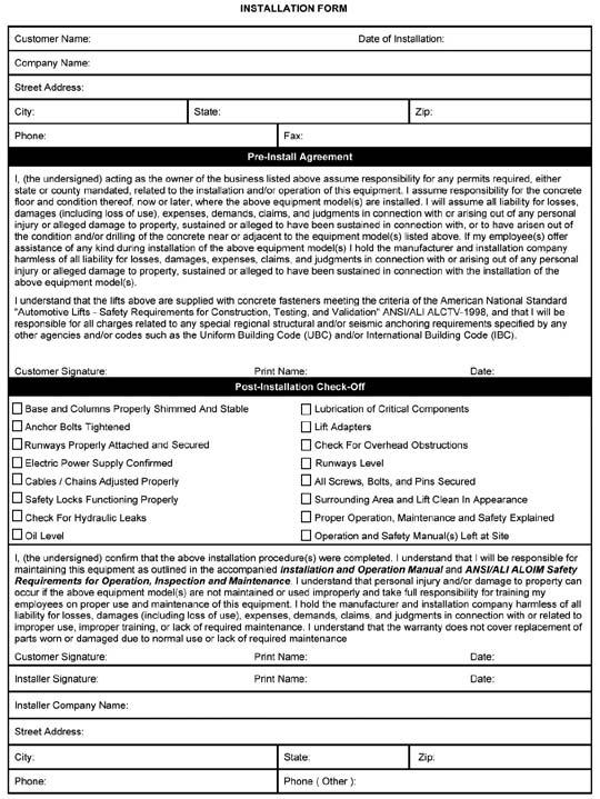
5 Table of Conens Conens Page No. Warrany / Serial Number Informaion Definiions of Hazard Levels Owner s Responsibiliy Before You Begin Clearances Insaller/Operaor Agreemen/ Proecive Equipmen Inroducion Safey / Warning Insrucions Tools Required Sep 1 / Selecing Sie Sep 2 / Floor Requiremens Concree Specificaions Assembly View / Descripion of Pars Floor Plan / General Specificaions Sep 3 / Sie Layou Sep 4 / Aligning he Ramp Assemblies Sep 5 / Power Uni Console Insallaion Sep 6 / Valve Floor Plae Insallaion Sep 7 / Valve Block Insallaion Sep 8 / Hydraulic Hose Connecion Sep 9 / Safey Air Line Connecion Sep 10 / Power Uni Hose Connecion Sep 11 / Power Uni Elecrical Connecion Sep 12 / Lif Sar-Up Sep 13 / Leveling he Ramps Sep 14 / Anchoring he Ramps Sep 15 / Insalling Approach Ramps Sep 16 / Insalling Accessories Sep 17 / Equalizing Procedure Sep 18 / Final Assembly Sep 19 / Operaion Sep 20 / Turnplae Pocke Adjusmen Sep 21 / Work Sep Insallaion Sep 22 / Hose Cover Insallaion Mainenance / Safe Lif Operaion Troubleshooing Guide Grease Por / Lubricaion Locaions Mainenance Records Insallaion Form Par Number Liss
6 INSTALLER / OPERATOR PLEASE READ AND FULLY UNDERSTAND. BY PROCEEDING YOU AGREE TO THE FOLLOWING. I have visually inspeced he sie where he lif is o be insalled and verified he concree o be in good condiion and free of cracks or oher defecs. I undersand ha insalling a lif on cracked or defecive concree could cause lif failure resuling in personal injury or deah. I undersand ha a level floor is required for proper insallaion and level lifing. I undersand ha I am responsible if my floor is of quesionable slope and ha I will be responsible for all charges relaed o pouring a new level concree slab if required and any charges. I undersand ha BendPak lifs are supplied wih concree faseners meeing he crieria of he American Naional Sandard Auomoive Lifs - Safey Requiremens for Consrucion, Tesing, and Validaion ANSI/ALI ALCTV-2006, and ha I will be responsible for all charges relaed o any special, regional, srucural, and/or seismic anchoring requiremens specified by any oher agencies and/or codes such as he Uniform Building Code (UBC) and/or Inernaional Building Code (IBC). I will assume full responsibiliy for he concree floor and condiion hereof, now or laer, where he above equipmen model is o be insalled. Failure o follow Danger, Warning, and Cauion insrucions may lead o serious personal injury or deah o operaor or bysander or damage o propery. I undersand ha BendPak lifs are designed o be insalled in indoor locaions only. Failure o follow insallaion insrucions may lead o serious personal injury or deah o operaor or bysander or damage o propery or lif. Failure o follow Danger, Warning, and Cauion insrucions may lead o serious personal injury or deah o operaor or bysander or damage o propery. Please read he enire manual prior o insallaion. Do no operae his machine unil you have read and have undersood all of he Danger, Warning and Cauion alers in his manual. For addiional copies or furher informaion, conac: BendPak Inc Lemonwood Dr. Sana Paula, CA INSTALLER / OPERATOR Proecive Equipmen Personal proecive equipmen helps makes insallaion and operaion safer, however, i does no ake he place of safe operaing pracices. Always wear durable work clohing during any insallaion and/or service aciviy. Shop aprons or shop coas may also be worn, however loose-fiing clohing should be avoided. Tigh-fiing leaher gloves are recommended o proec he echnician s hands when handling pars. Surdy leaher seel-oe work shoes and oil resisan soles should be used by all service personnel o help preven injury during ypical insallaion and operaion aciviies. 6 Eye proecion is essenial during insallaion and operaion aciviies. Safey glasses wih side shields, goggles, or face shields are accepable. Back bels provide suppor during lifing aciviies and are also helpful in providing worker proecion. Consideraion should also be given o he use of hearing proecion if service aciviy is performed in an enclosed area, or if noise levels are high. THIS SYMBOL POINTS OUT IMPORTANT SAFETY INSTRUCTIONS WHICH IF NOT FOLLOWED COULD ENDANGER THE PERSONAL SAFETY AND/OR PROPERTY OR YOURSELF AND OTHERS AND CAN CAUSE PERSONAL INJURY OR DEATH. READ AND FOLLOW ALL INSTRUCTIONS IN THIS MANUAL BEFORE ATTEMPTING TO OPERATE THIS MACHINE.
7 INTRODUCTION 1. Carefully remove he craing and packing maerials. CAUTION! Be careful when cuing seel banding maerial as iems may become loose and fall causing personal harm or injury. 2. Check he volage, phase, and proper amperage requiremens for he moor shown on he moor plae. Elecrical work should be performed only by a cerified elecrician. IMPORTANT SAFETY INSTRUCTIONS Read hese safey insrucions enirely. Do no aemp o insall his lif if you have never been rained on basic auomoive lif insallaion procedures. Never aemp o lif componens wihou proper lifing ools such as forklif or cranes. Say clear of any moving pars ha may fall and cause injury. When using your garage equipmen, basic safey precauions should always be followed, including he following: 1. Read and undersand all insrucions and all safey warnings before operaing lif. 2. Care mus be aken as burns can occur from ouching ho pars. 3. Do no operae equipmen wih a damaged cord or if he equipmen has been dropped or damaged unil i has been examined by a qualified service person. 4. Do no le a cord hang over he edge of he able, bench, or couner or come in conac wih ho manifolds or moving fan blades. 5. If an exension cord is necessary, a cord wih a curren raing equal o or more han ha of he equipmen should be used. Cords raed for less curren han he equipmen may overhea. Care should be aken o arrange he cord so ha i will no be ripped over or pulled. 6. Always unplug equipmen from elecrical oule when no in use. Never use he cord o pull he plug from he oule. Grasp plug and pull o disconnec. 7. Le equipmen cool compleely before puing away. Loop cord loosely around equipmen when soring. 8. To reduce he risk of fire, do no operae equipmen in he viciniy of open conainers of flammable liquids (gasoline). 9. Adequae venilaion should be provided when working on operaing inernal combusion engines. 10. Keep hair, loose clohing, fingers, and all pars of body away from moving pars. Keep fee clear of lif when lowering. Avoid pinch poins. 11. DANGER! To reduce he risk of elecric shock, do no use on we surfaces or expose o rain. The power uni used on his lif conains high volage. Disconnec power a he recepacle or a he circui breaker swich before performing any elecrical repairs. Secure plug so ha i canno be accidenally plugged in during service. or mark circui breaker swich so ha i canno be accidenally swiched on during service. 12. Use only as described in his manual. Use only manufacurer s recommended aachmens. 13. ALWAYS WEAR SAFETY GLASSES. Everyday eyeglasses only have impac resisan lenses, hey are no safey glasses. 14. Consider work environmen. Keep work area clean. Cluered work areas invie injuries. Keep areas well li. 15. Guard agains elecric shock. This lif mus be grounded while in use o proec operaor from elecric schock. Never connec he green power cord wire o a live erminal. This is for ground only. 16. Only rained operaors should operae his lif. All nonrained personnel should be kep away from he work area. Never le non-rained personnel come in conac wih, or operae lif. 17. DO NOT override self-closing lif conrols. 18. Clear area if vehicle is in danger of falling. 19. ALWAYS make sure he safeies are engaged before aemping o work on or near a vehcile. 21. WARNING! RISK OF EXPLOSION. This equipmen has inernal arcing or sparking pars which should no be exposed o flammable vapors. This machine should no be locaed in a recessed area or below floor level. 22. MAINTAIN WITH CARE. Keep lif clean for beer and safer performance. Follow manual for proper lubricaion and mainenance insrucions. Keep conrol handles and/or buons dry, clean and free from grease and oil. 23. Check for damaged pars. Check for alignmen of moving pars, breakage of pars or any condiion ha may affec operaion of lif. Do no use lif if any componen is broken or damaged. 24. NEVER remove safey relaed componens from he lif. Do no use lif if safey relaed componens are missing or damaged. 23. STAY ALERT. Use common sense and wach wha you are doing. Remember, SAFETY FIRST. SAVE THESE INSTRUCTIONS 7
8 Roary Hammer Drill or Similar 3/4 Masonry Bi Hammer 4 Foo Level Open-End Wrench Se: SAE/Meric Socke And Rache Se: SAE/Meric Hex-Key / Allen Wrench Se TOOLS REQUIRED IMPORTANT NOTICE THESE INSTRUCTIONS MUST BE FOLLOWED TO INSURE PROPER INSTALLATION AND OPERATION OF YOUR LIFT. FAILURE TO COMPLY WITH THESE INSTRUCTIONS CAN RESULT IN SERIOUS BODILY HARM AND VOID PRODUCT WARRANTY. MANUFACTURER WILL ASSUME NO LIABILITY FOR LOSS OR DAMAGE OF ANY KIND, EXPRESSED OR IMPLIED, RESULTING FROM IMPROPER INSTALLATION OR USE OF THIS PRODUCT. Please read enire manual prior o insallaion STEP 1 (Selecing Sie) Before insalling your new lif, check he following. Large Crescen Wrench Large Pipe Wrench Crow Bar Chalk Line Medium Fla Screwdriver Tape Measure: 25 Foo Minimum Needle Nose Pliers 1. LIFT LOCATION: Always use archiecural plans when available. Check he layou dimension agains he floor plan requiremens making sure ha adequae space if available. 2. OVERHEAD OBSTRUCTIONS: The area where he lif will be locaed should be free of overhead obsrucions such as heaers, building suppors, elecrical lines ec. 3. DEFECTIVE FLOOR: Visually inspec he sie where he lif is o be insalled and check for cracked or defecive concree. 4. Your new BendPak Scissor lif is designed for INDOOR INSTALLATION ONLY. DO NOT insall or use his lif on any asphal surface or any surface oher han concree. DO NOT insall or use his lif on expansion seams or on cracked or defecive concree. DO NOT insall or use his lif on a second / elevaed floor wihou firs consuling building archiec. DO NOT insall or use his lif oudoors. STEP 2 (Floor Requiremens) This lif mus be insalled on a solid level concree floor wih no more han 3-degrees of slope. Failure o do so CONCRETE SPECIFICATIONS LIFT MODEL CONCRETE REQUIREMENTS xr Min. Thickness / 3,000 PSI xr-12000a 4 Min. Thickness / 3,000 PSI could cause personal injury or deah. A level floor is suggesed for proper use and insallaion and level lifing. If a floor is of quesionable slope, consider a survey of he sie and/or he possibiliy of pouring a new level concree slab. DANGER! ALL MODELS MUST BE INSTALLED ON 3000 PSI CONCRETE ONLY CONFORMING TO THE MINIMUM REQUIREMENTS SHOWN ABOVE. NEW CONCRETE MUST BE ADEQUATELY CURED FOR A MINIMUM OF 28 DAYS. IMPORTANT NOTE BendPak lifs are supplied wih insallaion insrucions and concree faseners meeing he crieria as prescribed by he American Naional Sandard "Auomoive Lifs - Safey Requiremens for Consrucion, Tesing, and Validaion" ANSI/ALI ALCTV Lif buyers are responsible for any special regional srucural and/or seismic anchoring requiremens specified by any oher agencies and/or codes such as he Uniform Building Code (UBC) and/or Inernaional Building Code (IBC). 8
9 When removing he lif from shipping angles, pay close aenion as he ramps can slide and can cause injury. Prior o removing he bols make sure he ramps are held securely by a fork lif or some oher heavy lifing device. PARTS INVENTORY Be sure o ake a complee invenory of pars prior o beginning insallaion. Descripion Power Uni Console 1 Lef Ramp Assembly 1 Righ Ramp Assembly 1 Drive-Up Ramps 2 Alignmen Turnplae (XR-12000A only) 2 Work Sep 2 Pars Box (Packing Lis Enclosed) 1 Pars Bag (Packaged in Par Box) 1 Qy Work Sep Righ Ramp Assembly Alignmen Turnplaes Power Uni Console Lef Ramp Assembly Drive-Up Ramp 9
 89.5 / 2272mm 89.5 / 2272mm F - Overall Widh w/ Console 133.3 / 3385mm 133.3 / 3385mm G - Ramp Heigh 6.")

10 Floor plan / General Specificaions Measuremen XR XR-12000A A - Overall Exended Lengh / 6927mm / 7627mm B - Widh w/ Seps / 3057mm / 3057mm C - Ramp Widh 23.8 / 604mm 23.8 / 604mm D - Beween Ramps 40.5 / 1028mm 40.5 / 1028mm E - Overall Widh (Baseplae o Baseplae) 89.5 / 2272mm 89.5 / 2272mm F - Overall Widh w/ Console / 3385mm / 3385mm G - Ramp Heigh 6.6 / 168mm 6.6 / 168mm H - Underramp Heigh 68.5 / 1741mm 68.5 / 1741mm J - Raised Heigh 75.2 / 1910mm 75.2 / 1910mm K - Collapsed Heigh 11.3 / 286mm 11.3 / 286mm L - Overall Collapsed Lengh / 6547mm / 7201mm Minimum 4 Wheel Alignmen Wheelbase* n/a 100 / 2540mm Maximum 4 Wheel Alignmen Wheelbase* n/a 165 / 4191mm Maximum 2 Wheel Alignmen Wheelbase* n/a 172 / 4369mm Minimum General Wheelbase* 140 / 3556mm 140 / 3556mm Maximum General Wheelbase* 178 / 4521mm 178 / 4521mm (*) May vary depending on wheel size 10
11 layou Fron Ramp End Rear Ramp End Fig 3.1 Sliding Pivo Baseplae STEP 3 (Sie Layou) 1. Selec an appropriae sie for where o insall your new sae-of-he-ar BendPak lif using he char on page Now deermine which direcion you would like he lif o face. A vehicle will approach he lif from he Rear Ramp End and drive forward o he Fron Ramp End. (See Fig 3.1) Fixed Pivo Baseplae line for he Fron baseplaes, as he Fron baseplaes are wider. 4. Keep all dimensions square wihin 1/8 (3mm) or malfuncion of he lif can occur. 5. CHECK ALL DIMENSIONS TWICE and make sure ha he layou is perfecly square. 3. Once a locaion is deermined, use a carpeners chalk line o layou a grid for he rear baseplae locaions. Rear baseplaes are used, as he Fron baseplaes slide. Make sure o snap he chalk line long enough for he enire lengh of he ramp. This is needed o provide a reference WARNING! KEEP ALL DIMENSIONS SQUARE WITHIN 1/8 OR MALFUNCTION OF LIFT MAY OCCUR Fig
12 STEP 4 (Aligning he Ramp Assemblies) Fig Lif he Lef Ramp Assembly and Righ Ramp assembly ino posiion and se he ramps down on o he layou creaed in Sep 4 2. Align he Rear Baseplaes wih he chalklines ha were drawn in Sep 4. (See Fig 4.1) Approach Fig Align he Fron Baseplaes wih he chalklines ha were drawn in Sep 4, using care so ha he Rear Baseplaes do no shif during alignmen. (See Fig 4.2) Fig DO NOT aemp o bol down he ramp assemblies a his ime. STEP 5 (Power Uni Console Insallaion) 1. Place he Power Uni Console nex o he Righ Ramp Assembly s rear fixed pivo baseplae. 2. Align he Power Uni Console and he righ-rear baseplae using he measuremens as shown in Figure Using he console s baseplae as a guide drill wo 3/8 holes ino he concree floor 1-1/2 deep making sure no o le he drill wobble. DO NOT ream he holes afer drilling. (See Fig 5.2) 4. Afer drilling, remove dus horoughly from each hole. 5. Assemble he washers and nus on he anchors hen ap ino each hole wih a hammer unil he washer ress agains he base plae. If shimming is required be sure ha enough hreads are lef exposed. (See Fig. 5.3) 12
 STEP 6 (Valve Floor Plae Insallaion) 1.")
 2. Using he Valve Floor Plae as a emplae, mark he four mouning holes on he concree underneah and se aside he Valve Floor Plae. 1-1/2 Deep 4.")

13 Fig 5.2 Fig /2 Deep Fig 5.3 Fig 5.4 Fig Wih anchor bols in place, ighen by securing he nu o he base hen urning 2-3 full urns clockwise. DO NOT use an impac wrench for his procedure. (See Fig. 5.4) STEP 6 (Valve Floor Plae Insallaion) 1. Inser he wo provided M8 screws ino he chamfered holes in he Valve Floor Plae and place he Valve Floor Plae in line wih he fron of he Power Uni Console and leave a 3/8 gap beween he wo componens. (See Fig 6.1) 2. Using he Valve Floor Plae as a emplae, mark he four mouning holes on he concree underneah and se aside he Valve Floor Plae. 1-1/2 Deep 4. Afer drilling remove dus horoughly, inser four plasic concree anchors in o he holes ha were drilled. 5. Replace he Valve Floor Plae so ha he anchors line up wih he mouning holes on he Valve Floor Plae. Make sure he Fla Head Screws are sill mouned in he Floor Plae as hey will be needed o moun he Valve Block assembly, and also make sure he Valve Floor Plae is oriened so ha he noched side faces away from he lif. Insall four M5 Pan Head shee meal screws o fasen he Valve Floor Plae o he concree. (See Fig 6.3) 3. Drill four holes a he locaions marked wih a 5/16 drill o a deph of 1-1/2. (See Fig 6.2) 13

 may pass hrough in he cu ous.")
14 CAUTION! DURING HOSE INSTALLATION, LOOSE HOSES POSE A TRIPPING HAZARD. BE AWARE OF LOOSE HOSES IN THE WORKSPACE TO AVOID INJURY. 3. Cover he grouping of hoses emporarily wih he long hose cover o preven ripping over he hoses. Align he cuous of he cover o he hose roughs so ha he hoses Fig 6.3 Fig 8.1 STEP 7 (Valve Block Insallaion) 1. Align he hrough holes of he Valve Block Assembly wih he screw suds ha are proruding from he Valve Plae and se he Valve Block down on o he plae. Using wo M8 Spring Lock washers and wo M8 nus, affix he Valve Block o he Valve Plae. (See Fig 7.1) may pass hrough in he cu ous. The coverplae will be anchored a a laer ime ṠTEP 9 (Safey Air Line Connecion) 1. Your new lif has been pre-plumbed wih 1/4 Poly-Flo air line hoses. Uncoil he air line hoses for boh he Lef and Righ ramp assemblies. (See Page 16 for rouing diagram) 2. DO NOT overighen bols. STEP 8 (Hydraulic Hose Connecion) Fig Your new lif has been pre-plumbed wih hydraulic hoses. Connec he pre-marked hose ends o he corresponding marked por on he valve block assembly. (Ex. - S1 is conneced o S1) (See Fig 8.1) 2. Check your lif s hose rouing agains he hose rouing diagram on page 15 o deermine all hoses are properly conneced Saring wih he air line on he Lef Ramp Assembly, follow he same roue wih he air line as ha of he hydraulic hoses. 3. Once he air line hose roue has reached he cener of he Righ Ramp Assembly s hose rough, cu he air line hose, and connec a Tee fiing o he air line end. 4. Roue he Righ Ramp Assembly s air line hose o he same Tee fiing as he one conneced in Iem Cu he air line hose o he lengh needed and connec o he Tee fiing. 6. Connec anoher lengh of Poly-Flo air line hose o he Tee and roue he air line hose using he same roue as he hydraulic hoses. 7. Roue he hose over he Valve Block Assembly and ino he Power Uni Console.
15 hydraulic HOSE ROUTING DIAGRAM F F A 1,143mm 45 B 1,956mm 77 C 3,886mm 152 D 4,928mm 194 E 5,842mm 230 F 6,147mm 242 G 6,198mm 244 H 6,680mm 262 I 7,087mm 279 J 10,317mm 406 K 11,024mm 434 K B C B J H E I G Plug D A 15
16 SAFETY AIR LINE ROUTING DIAGRAM LEFT SIDE RAMP RIGHT SIDE RAMP AIR CYLINDER AIR CYLINDER AIR CYLINDER TEE FITTING AIR CYLINDER AIR PUSH BUTTON APPROACH floor rough 16
17 STEP 10 (Power Uni Hose Connecion) 1. Remove fron panel from Power Uni Console o access power uni and conrols. 2. Remove Power Por plug from Power Uni and insall he 90 Fiing w/ O-ring ino he Power Por on he Power Uni. Connec he Power Uni Hose Assembly o he 90 Fiing. (See Fig 10.1) 3. Connec he Power Uni Hose Assembly o he Valve Block Assembly. (See Fig 10.1) 90 Fiing w/ O-Ring Fig Connec he Air Push Buon o your compressed air supply. Be sure ha your compressed air supply does no exceed 125 PSI. STEP 11 (Power Uni Elecrical Connecion) 1. The sandard power uni for your lif is 220 vol, 60HZ, single phase. All wiring mus be performed by a cerified elecrician only. SEE WIRING INSTRUCTIONS AFFIXED TO MOTOR FOR PROPER WIRING INSTRUCTIONS. 2. Roue Power Cable hrough he hole in Rear of Power Uni Console. DANGER! ALL WIRING MUST BE PERFORMED BY A LICENSED ELECTRICIAN. Power Uni Hose Assembly Valve Block Assembly DANGER! DO NOT PERFORM ANY MAINTENANCE OR INSTALLATION OF ANY COMPONENTS WITHOUT FIRST ENSURING THAT ELECTRICAL POWER HAS BEEN DISCONNECTED AT THE SOURCE OR PANEL AND CANNOT BE RE-ENERGIZED UNTIL ALL MAINTENANCE AND/OR INSTALLATION PROCEDURES ARE COMPLETED. WARNING! DO NOT RUN POWER UNIT WITHOUT OIL. DAMAGE TO POWER UNIT PUMP CAN OCCUR. THE POWER UNIT MUST BE KEPT DRY. DAMAGE TO POWER UNIT CAUSED BY WATER OR OTHER LIQUIDS SUCH AS DETERGENTS, ACID ETC., IS NOT COVERED UNDER WARRANTY. 4. Connec he Poly-Flo air line hose ha was roued in Sep 10 o he Air Push Buon. (See Fig 10.2) Air Supply In Fig OPERATE LIFT ONLY BETWEEN TEMPERATURES OF F. IMPROPER ELECTRICAL HOOK-UP CAN DAMAGE MOTOR AND WILL NOT BE COVERED UNDER WARRANTY. MOTOR CAN NOT RUN ON 50HZ WITHOUT A PHYSICAL CHANGE IN THE MOTOR. USE A SEPARATE CIRCUIT BREAKER FOR EACH POWER UNIT. PROTECT EACH CIRCUIT WITH TIME DELAY FUSE OR CIRCUIT BREAKER. FOR VOLT, SINGLE PHASE, USE A 25 AMP FUSE. FOR VOLT, THREE PHASE, USE A 20 AMP FUSE. FOR VOLT, THREE PHASE, USE A 15 AMP FUSE.


18 220V Wiring Diagram 380V Wiring Diagram 18

19 DANGER! DO NOT PERFORM ANY MAINTENANCE OR INSTALLATION OF ANY COMPONENTS WITH OUT FIRST ENSURING THAT ELECTRICAL POWER HAS BEEN DISCONNECTED AT THE SOURCE OR PANEL AND CANNOT BE RE-ENERGIZED UNTIL ALL MAINTENANCE AND/OR INSTALLATION PROCEDURES ARE COMPLETED. IMPORTANT POWER-UNIT INSTALLATION NOTES DO NOT run power uni wihou oil. Damage o pump can occur. The power uni mus be kep dry. Damage o power uni caused by waer or oher liquids such as deergens, acid ec., is no covered under warrany. Improper elecrical connecion can damage moor and will no be covered under warrany. Moor can no run on 50HZ wihou a physical change in he moor. Use a separae breaker for each power uni. Proec each circui wih ime delay fuse or circui breaker. For vol, single phase, use a 25 amp fuse. For vol, hree phase, use a 20 amp fuse. For vol, hree phase, use a 15 amp fuse. Insallaion and adjusmen. DO NOT aemp o raise vehicle unil a horough operaion check has been compleed. All wiring mus be performed by a cerified elecrician only. SEE WIRING INSTRUCTIONS AFFIXED TO MOTOR FOR PROPER WIRING INSTRUCTIONS. 19
20 STEP 12 (Lif Sar-Up) STEP 13 (Leveling he Ramps) CAUTION! DURING THE START-UP PROCEDURE, OBSERVE ALL OPERATING COMPONENTS AND CHECK FOR PROPER INSTALLATION AND ADJUSTMENT. DO NOT ATTEMPT TO RAISE VEHICLE UNTIL A THOROUGH OPERATIONAL CHECK HAS BEEN COMPLETED. WARNING! BEFORE PROCEEDING POSITION THE RUNWAYS MAKING SURE THEY ARE PARALLEL AND SQUARE AS SHOWN BELOW 1. Make sure he Power Uni reservoir is full wih eigh (8) gallons of AW32 hydraulic oil. 2. Lubricae all fricion poins on he lif wih axle grease wih a grease gun hrough he grease pors. 3. Wih he ball valves on he Valve Block Assembly open, es he power uni by depressing he Up swich. If he moor sounds like i is operaing properly, raise he lif and check all hose connecions for leaks. IF MOTOR GETS HOT OR SOUNDS PECULIAR, STOP IMMEDIATELY AND RE-CHECK HOSE AND ELECTRICAL CONNECTIONS. 4. Coninue raising he lif slowly unil THE LIFT CYLINDERS REACH THEIR FULLEST EXTENSION. 5. Place he hose covers over he hoses o shield hem from being accidenally crushed by he lif. Do no anchor he covers now. The covers will be anchored in a laer sep. 6 Wih he ball valves on he Valve Block Assembly closed, Press he AIR SAFETY release buon and he LOWER BUTTON simulaneously o lower he lif o he floor. 6. Repea he lifing and lowering process a leas hree imes o equalize he oil pressure in each cylinder. WARNING! WHEN LOWERING THE LIFT PAY CAREFUL ATTEN- TION THAT ALL PERSONNEL AND OBJECTS ARE KEPT CLEAR. ALWAYS KEEP A VISUAL LINE OF SITE ON THE LIFT AT ALL TIMES. ALWAYS MAKE SURE THAT ALL LOCKS ARE DISENGAGED. IF ONE OF THE LOCKS INADVERTENTLY LOCKS ON DE- SCENT THE LIFT AND/OR VEHICLE MAY DISRUPT CAUSING PERSONAL INJURY OR DEATH. 20 Fig The lif will be leveled o he highes poin on he floor. 2. To find he highes poin, use a four foo level across he base frame or on op off each Runway. 3. Beginning a he corner closes o he highes poin, shim a each bol hole locaion unil each Runway is level. 4. Coninue shimming each Runway unil hey are level fron o back. 5. Once he runways are level fron o back, level he inside and ouside rails of each Runway o make sure each Runway is level laerally as well as fron o back. Noe: BEFORE ANCHORING THE LIFT TO THE FLOOR, FIRST RAISE THE LIFT UP AND DOWN AND CHECK FOR PROPER OPERATION AND SQUARENESS OF FRAMES AND RUNWAYS. Noe: WHEN SHIMMING BE SURE TO USE SLOTTED SHIMS AROUND EACH ANCHOR BOLT LOCATION SO THAT THE CONCRETE SURROUNDING THE ANCHOR BOLTS REMAINS COMPRESSED. THIS WILL HELP PREVENT THE CONCRETE FROM CRACKING NEAR THE ANCHOR BOLTS.

21 STEP 14 (Anchoring he Ramps) NOTE: BENDPAK LIFTS ARE SUPPLIED WITH INSTALLATION INSTRUCTIONS AND CONCRETE FASTENERS MEET- ING THE CRITERIA AS PRESCRIBED BY THE AMERI- CAN NATIONAL STANDARD "AUTOMOTIVE LIFTS - SAFETY REQUIREMENTS FOR CONSTRUCTION, TESTING, AND VALIDATION" ANSI/ALI ALCTV LIFT BUYERS ARE RESPONSIBLE FOR ANY SPECIAL REGIONAL STRUCTURAL AND/OR SEISMIC ANCHOR- ING REQUIREMENTS SPECIFIED BY ANY OTHER AGENCIES AND/OR CODES SUCH AS THE UNIFORM BUILDING CODE (UBC) AND/OR INTERNATIONAL BUILDING CODE (IBC). 3. Afer drilling he anchor holes, remove he dus horoughly from each hole using compressed air and/or wire brush. ALWAYS WEAR SAFETY GOGGLES. 4. Assemble he washers and nus on he anchors hen ap ino each hole wih a hammer unil he washer ress agains he base. Be sure ha if shimming is required, enough hreads are lef exposed. (See Fig. 14.2) 5. If shimming is required, inser he shims as necessary around each Anchor Bols. (See Fig. 14.3) Fig Before proceeding, make cerain he lif is posiioned wih proper clearances around and overhead. NOTE: A LEVEL FLOOR IS SUGGESTED FOR PROPER INSTALLATION. SMALL DIFFERENCES IN FLOOR SLOPE MAY BE COMPENSATED FOR BY PROPER SHIMMING. ANY MAJOR SLOPE DIFFERENCES WILL AFFECT LEVEL LIFTING. IF A FLOOR IS OF QUESTIONABLE SLOPE, (MORE THAN 1 SIDE TO SIDE OR 2 WITHIN THE FULL LENGTH OF THE LIFT) CONSIDER POURING A NEW CONCRETE SLAB. 6. Wih he shims and Anchor Bols in place, ighen nu hree o five urns pas finger igh. DO NOT use an impac wrench for his procedure. (See Fig. 14.4) 2. Using he base of he frame as a guide, drill each anchor hole in he concree approximaely 4 deep using a roary hammer drill and 3/4 concree drill-bi. (See Fig 14.1) STEP 15 (Insalling Approach Ramps) Fig 14.4 Fig 14.1 Fig Wih he ramps in he collapsed posiion, place he Drive-Up ramps cenered wih he Lef and Righ ramp assemblies making sure here is a 3-3/4 gap in beween each respecive ramp assembly and Approach Ramp. (See Fig 15.1) Ramp Assembly " Approach Ramp Assembly 21 Fig 15.1
 Mark Anchor Holes Fig 15.2 3.")
22 2. Using chalk or crayon, mark he he floor anchor bol holes on he concree. (See Fig. 15.2) 6. Wih he shims and Anchor Bols in place, ighen nu hree o five urns pas finger igh. DO NOT use an impac wrench for his procedure. (See Fig. 15.5) Mark Anchor Holes Fig Remove he approach ramps and drill each anchor hole for he approach ramps in he concree approximaely 4 deep using a roary hammer drill and 3/4 concree drillbi. (See Fig 15.3) STEP 16 (Insalling Accessories) Fig Place he Turnplaes in he Turnplae pockes (Alignmen Model Only). Level he Turnplae Pockes as show in Sep 20 on page Insall he Fron Tire sops using he Hinge Pins and C-clips as shown. (See Fig. 16.1) Fig Afer drilling he anchor holes, remove he dus horoughly from each hole using compressed air and/or wire brush. ALWAYS WEAR SAFETY GOGGLES. 5. Replace he approach ramps and align he holes ha were drilled in he concree wih he anchor holes on he approach ramps. 6. Assemble he washers and nus on he anchors hen ap ino each hole wih a hammer unil he washer ress agains he base. (See Fig. 15.4) Fig 15.4 Fig Insall he Flip Up Ramps using he Flip Up ramp Bracke Pins and C-clips as shown. (See Fig. 16.2) 22 Fig 16.2

23 STEP 17 (Equalizing Procedure) 5. Afer he hydraulic cylinders are flooded, posiion he handles on he valve body back o he closed posiion- PERPENDICULAR WITH THE FLOOR. (See Fig 17.2) 6. Compleely lower he lif all he way o he floor. WARNING! EQUALIZER VALVES MUST REMAIN IN THE CLOSED POSITION DURING NORMAL OPERATION. FAILURE TO CLOSE VALVES DURING NORMAL OPERATION MAY DAMAGE LIFT STRUCTURE. 1. Remove Valve Cover. 2. Posiion he handles on he Valve Block Assembly so ha handles are PARALLEL wih he floor. (See Fig 17.1) Fig Raise he lif midway and lock a even Safey Lock posiions. 8. Afer a visual confirmaion ha boh sides are on he SAME LOCK POSITION, open he valve handles. (Posiion he handles so ha he handles are PARALLEL wih he floor. ) You may hear a swoosh as he fluid in all four cylinders equalizes. Once his is done (afer abou 10-seconds) close he valve handles. 9. Your lif should now be equalized. Be sure o repea his procedure every 30-days. 10. Re-insall Valve Cover. STEP 18 (Final Assembly) 1. Tighen all assembly and Anchor Bols securely. 2. Run he lif up and down a few imes o be sure ha he locks are engaging uniformly and ha he safey release mechanisms are funcioning properly. Re-adjus if necessary. 3. Drive a vehicle ono he lif making sure o se he emergency brake before exiing he vehicle. 3. Nex, raise he UNLOADED lif all he way. The ramps may raise unevenly during his ime. 4. Raise he lif unil boh ramps reach full heigh and he hydraulic cylinders boom ou. Once he lif sops raising, coninue pressing he power uni buon for 15 seconds o flood all hydraulic cylinders wih hydraulic oil. Fig Cycle he lif up and down wo imes wih a vehicle loaded on he ramps o ensure ha he locks are engaging uniformly and ha he safey release mechanisms are funcioning properly. Re-adjus if necessary. RAMP INSTALLATION CHECKLIST 4 Ramp Assemblies Properly Shimmed And Sable 4 Anchor Bols Tighened 4 Pivo Pins Properly Secure 4 Elecric Power Supply Confirmed 4 Equalizing Procedure Complee 4 Safey Locks Funcioning Properly 4 Check For Hydraulic Leaks 4 Lubricaion of Criical Componens 4 All Screws, Bols, and Pins Secured 4 Operaion and Safey Manuals On Sie 23 CAUTION! WHEN RAISING LOADED LIFT PAY ATTENTION TO CEILING CLEARANCE WITH RESPECT TO THE LOAD. FAILURE TO DO SO MAY CAUSE PROPERTY DAMAGE. BENDPAK INC. IS NOT LIABLE FOR OPERATOR NEGLIGENCE.


 3. Before raising vehicle, be sure all personnel are clear of he lif and surrounding area.")
24 To Raise Lif: STEP 19 (Operaion) 1. Posiion vehicle ires in he cener of each Runway. 2. Se parking brake and use Wheel Chocks o hold vehicle in posiion. (See Fig. 19.1) Fig 19.1 DANGER! WHEN LOWERING THE LIFT PAY CLOSE ATTENTION THAT ALL PERSONNEL AND OBJECTS ARE KEPT CLEAR. ALWAYS KEEP A VISUAL LINE OF SIGHT ON THE LIFT AT ALL TIMES. ALWAYS MAKE SURE THAT ALL LOCKS ARE DISENGAGED. IF A SAFETY LOCK ENGAGES INADVERTENTLY UPON DESCENT, THE LIFT MAY MALFUNCTION CAUSING THE LOADED VEHICLE TO SHIFT UNDESIREABLY AND MAY CAUSE PERSONAL INJURY AND/OR DEATH. To Lower Lif: 1. Before lowering vehicle, be sure all personnel are clear of he lif and surrounding area. Pay careful aenion o overhead clearances. Be sure ha all ools and equipmen have been cleared from under he lif. Wheel Chock 2. Raise he lif off of he Safey Locks by pressing he push buon on he Power Console. Make sure he lif is raised by a leas wo inches o allow adequae clearance for he locks o clear. 3. Press he Push Buon Air Safey Valve and HOLD. The safeies will disengage. (See Fig. 19.3) 3. Before raising vehicle, be sure all personnel are clear of he lif and surrounding area. Pay careful aenion o overhead clearances. 4. Raise he lif o he desired heigh by pressing he push buon on he power uni. Safey Ladder Window Fig Afer vehicle is raised o he desired heigh, lower he lif ono he neares safey lock. ALWAYS MAKE SURE THAT ALL SAFETY LOCKS ARE ENGAGED before enering work area. (See Fig ) Safey Ladder Window Fig 19.2 Safey Lock Safey Lock Disengaged 4. Push he LOWERING BUTTON on he Power Uni Console unil he lif has descended compleely. STEP 20 (Turnplae Pocke Adjusmen) Safey Lock Safey Lock Engaged Afer he lif insallaion, operaion check and leveling of he lif has been compleed. 2. Lower he lif ono he safeies a a convenien heigh. 3. Adjus he Turnplae pockes o level using he six adjusmen bols. (See Fig. 20.1)
 Work Sep CAUTION! BE AWARE OF RAMP POSITION AND PARTS PROTRUDING FROM RAMPS.")

25 Fig 20.1 STEP 22 (Hose Cover Insallaion) 1. Raise ramps o provide ease of insallaion for his sep. Leveling Bols STEP 21 (Work Sep Insallaion) 1. Insall he Sep Anchors in he desired locaions on he ramp assemblies using he provided M10 hardware. (See Fig 21.1) Work Sep CAUTION! BE AWARE OF RAMP POSITION AND PARTS PROTRUDING FROM RAMPS. INATTENTIVENESS MAY RESULT IN PERSONAL INJURY. 2. Check fimen of he wo floor roughs by placing hem over he hose bundles. The Under Ramp Floor Trough should be placed under he ramps, wih he cuous facing he base plaes as he hoses from he ramps will be mouned hrough hem. The shorer Floor Trough should be placed in beween he Under Ramp Floor Trough and he Valve Floor Plae Assembly. 3. Once he wo roughs are in place, use he Under Ramp Floor Trough as a emplae, mark he four mouning holes on he concree underneah wih chalk or crayon and se aside he floor roughs. 4. Drill four holes a he locaions marked wih a 5/16 drill o a deph of 1-1/2. (See Fig 22.1) Pay aenion o hose posiions. DO NOT damage or pierce he hydraulic or pneumaic hoses. Fig 22.1 Sep Anchor 2. Align he Sep Anchors wih he keyhole slos on he Work Sep. Fi he keyhole slos over he Sep Anchors and drop he sep ino place. 3. To remove he Work Sep, push he Work Sep upwards so ha he keyhole slos will be able o fi over he Sep Anchors and pull he Work Sep away from he ramp. Leave he Sep Anchors in place for ease of insallaion of he Work Sep for he nex use. 4. To re-insall, repea Sep 21 Iem 2. Fig 21.1 DANGER! PRIOR TO WORKING UNDERNEATH THE LIFT, MAKE CERTAIN SAFETY LOCKS ARE ENGAGED TO PREVENT LIFT FROM UNEXPECTEDLY LOWERING /2 Deep 5. Afer drilling remove dus horoughly, inser four plasic concree anchors in o he holes ha were drilled. 6. Replace he floor roughs so ha he anchors line up wih he mouning holes on he wo floor roughs. Insall four M5 Pan Head shee meal screws o fasen he floor roughs o he concree.
26 Weekly Mainenance 1. Lubricae all pivo pins wih general purpose grease a specified locaions found on page Check all componen connecions, bols and pins o insure proper mouning. 3. Lubricae safey lock pivo poins wih general purpose ligh spray-oil. Monhly Mainenance 1. Check safey locks o insure hey are in good operaing condiion. 2. Check all hoses for excessive signs of wear. 3. Make a visual inspecion of ALL MOVING PARTS and check for excessive signs of wear. 4. Replace ALL FAULTY PARTS before lif is pu back ino operaion. NEVER EXCEED THE RATED CAPACITY of lif. DO NOT USE LIFT if any componen is found o be defecive or worn. NEVER OPERATE LIFT wih any person or equipmen below. ALWAYS STAND CLEAR of lif when lowering or raising. ALWAYS INSURE SAFETY LOCKS ARE ENGAGED before enering work area. NEVER LEAVE LIFT IN ELEVATED CONDITION unless all safey locks are engaged. Auomoive and ruck lifs are criical o he operaion and profiabiliy of your business. The safe use of his and oher lifs in your shop is criical in prevening employee injuries and damage o cusomer s vehicles. By operaing lifs safely you can insure ha your shop is profiable, producive and safe. Safe operaion of auomoive lifs requires ha only rained employees should be allowed o use he lif. Training should include, bu no limied o: Proper posiioning of he vehicle on he runway. (See manufacurers minimize wheel base loading requiremens.) Safe Lif Operaion A daily inspecion of he lif should be compleed prior o is use. Safey devices, operaing conrols, lif arms and oher criical pars should be inspeced prior o using he lif. All mainenance and repairs of he lif should be compleed by following he manufacurer s requiremens. Lif repair pars should mee or exceed OEM specificaions. Repairs should only be compleed by a qualified lif echnician. The vehicle manufacurer s recommendaions should be used for spoing and lifing he vehicle. Lif Operaion Safey Use of he operaing conrols. Undersanding he lif capaciy. Proper use of jack sands or oher load supporing devices. Proper use, undersanding and visual idenificaion of safey lock devices and heir operaion. Reviewing he safey rules. Proper housekeeping procedures (lif area should be free of grease, oil, ools, equipmen, rash, and oher debris) 26 I is imporan ha you know he load limi. Be careful ha you do no overload he lif. If you are unsure wha he load limi is, check he daa plae found on one of he lif columns or conac he manufacurer. The cener of graviy should be followed closely o wha he manufacurer recommends. Always make sure you have proper overhead clearance. Addiionally, check ha aachmens, (vehicle signs, campers anennas, ec) are no in he way. Be sure ha prior o he vehicle being raised, he doors, runk, and hood are closed securely
27 Prior o being raised, make sure here is no one sanding closer han six fee from he lif Safe Lif Operaion (Con d) Read and undersand all safey warning procedures before operaing lif. Afer posiioning he vehicle on he lif runways, se he emergency brake, make sure he igniion is off, he doors are closed, overhead obsrucions are cleared, and he ransmission is in neural. Double check ha he auomaic chock devices are in posiion and hen when he lif is raised, observe he chocks Pu pads or adapers in he righ posiion under he conac poins ha have been recommended The lif should be raised jus unil he vehicle s wheels are abou one foo off he ground. If conac wih he vehicle is uneven or i appears ha he vehicle is no siing secure, carefully lower he lif and readjus. Always consider poenial problems ha migh cause a vehicle o slip, i.e., heavy cargo, undercoaing, ec. Pay aenion when walking under a vehicle ha is up on he hydraulic lif. Do no leave he conrols while he lif is sill in moion. Do no sand direcly in fron of he vehicle or in he bay when vehicle is being loaded or driven ino posiion. Do no go near vehicle or aemp o work on he vehicle when being raised or lowered. Remain clear of lif when raising or lowering vehicle. Do no rock he vehicle while on he lif or remove any heavy componen from vehicle ha may cause excessive weigh shif. Keep hands and fee clear. Remove hands and fee from any moving pars. Keep fee clear of lif when lowering. Avoid pinch poins. Only rained operaors should operae his lif. All non-rained personnel should be kep away from work area. Never le non-rained personnel come in conac wih, or operae lif. Use lif correcly. Use lif in he proper manner. Never use lifing adapers oher han wha is approved by he manufacurer. Do no override self-closing lif conrols. Clear area if vehicle is on danger of falling. Say aler. Wach wha you are doing. Use common sense. Be aware. Check for damaged pars. Check for alignmen of moving pars, breakage of pars or any condiion ha may affec is operaion. Do no use lif if any componen is broken or damaged. Never remove safey relaed componens from he lif. Do no use lif if safey relaed componens are damaged or missing. When he lif is being lowered, make sure everyone is sanding a leas six fee away. Be sure here are no jacks, ools, equipmen, lef under he lif before lowering. Always lower he vehicle down slowly and smoohly. Do no lower he vehicle unil people, maerials, and ools are clear Always insure ha he safeies are engaged and lowered on o he safey locks before any aemp is made o work on or near vehicle. Some vehicle mainenance and repair aciviies may cause he vehicle o shif. Follow he manufacurer s guidelines when performing hese operaions. The use of jack sands or alernae lif poins may be required when compleing some repairs. 27
28 LIFT WILL NOT RAISE POSSIBLE CAUSE 1. Air in oil, (1,2,8,13) 2. Cylinder binding, (9) 3. Cylinder leaks inernally, (9) 4. Moor run backward under pressure, (11) 5. Lowering valve leaks, (3,4,6,10,11) 6. Moor runs backwards, (7,14,11) 7. Pump damaged, (10,11) 8. Pump won prime, (1,8,13,14,3,12,10,11) 9. Relief valve leaks, (10,11) 10. Volage o moor incorrec, (7,14,11) Remedy Insrucion 1. Check for proper oil level The oil level should be up o he bleed screw in he reservoir wih he lif all he way down. 2. Bleed cylinders See Insallaion Manual 3. Flush release valve o ge rid of Hold release handle down and sar uni allowing possible conaminaion i o run for 15 seconds. 4. Diry oil Replace oil wih clean AW32 hydraulic oil. 5. Tighen all faseners Tighen faseners o recommended orques. 6. Check for free movemen of release If handle does no move freely, replace bracke or handle assembly. 7. Check if moor is wired correcly compare wiring of moor o elecrical diagram on drawing. 8. Oil seal damaged or cocked Replace oil seal around pump shaf. 9. See Insallaion Manual Conac BendPak Cusomer Suppor. 10. Replace wih new par Replace wih new par. 11. Reurn uni for repair Reurn uni for repair. 12. Check pump-mouning bols Bols should be 15 o 18 f. lbs. 13. Inle screen clogged Clean inle screen or replace. 14. Check wall oule volages and wiring Make sure uni and wall oule are wired properly. 28
29 MOTOR WILL NOT RUN POSSIBLE CAUSE 1. Fuse blown, (5,2,1,3,4) 2. Limi swich burned ou, (1,2,3,4) 3. Microswich burned ou, (1,2,3,4) 4. Moor burned ou, (1,2,3,4,6) 5. Volage o moor incorrec, (2,1,8) Remedy insrucion 1. Check for correc volage Compare supply volage wih volage on moor name ag. Check ha he wire is sized correcly. N.E.C. able requires AWG 10 for 25 Amps. 2. Check moor is wired correcly compare wiring of moor o elecrical diagram on drawing. 3. Don use exension cords According o N.E.C. : The size of he conducors should be such ha he volage drop would no exceed 3% o he farhes oule for power Do no run moor a 115 VAC damage o he moor will occur. 4. Replace wih new par replace wih new par. 5. Rese circui breaker/fuse rese circui breaker/fuse. 6. Reurn uni for repair Reurn uni for repair. 7. See Insallaion Manual See Insallaion Manual. 8. Check wall oule volage and wiring Make sure uni and wall oule is wired properly. Moor mus run a 208/230 VAC. LIFT LOWERS SLOWLY OR NOT AT ALL POSSIBLE CAUSE 1. Cylinders binding, (1) 2. Release valve clogged, (5,4,2,3) 3. Pressure fiing oo long, (6) Remedy insrucion 1. See Insallaion Manual Conac BendPak Cusomer Suppor. 2. Replace wih new par Replace wih new par. 3. Reurn for repair Reurn for repair. 4. Check oil Use clean AW32 hydraulic oil only. If oil is conaminaed, replace wih clean hydraulic oil and flush enire sysem. 5. Clean release valve Wash release valve in solven and blow ou wih air. 6. Replace fiing wih shor hread lead Replace fiing wih shor hread lead. 29
30 WILL NOT RAISE LOADED LIFT POSSIBLE CAUSE 1. Air in oil, (1,2,3,4) 2. Cylinder binding, (5) 3. Cylinder leaks inernally, (5) 4. Lif overloaded, (6,5) 5. Lowering valve leaks, (7,8,1,5,9) 6. Moor runs backwards, (10,12,9) 7. Pump damaged, (5,9) 8. Pump won prime, (1,2,3,4,5,11,9) 9. Relief valve leaks, (8,5,9) 10. Volage o moor incorrec, (10,12,5) Remedy insrucion 1. Check oil level The oil level should be up o he bleed screw in he reservoir wih he lif all he way down. 2. Check/Tighen inle ubes Replace inle hose assembly. 3. Oil seal damaged or cocked Replace oil seal and insall. 4. Bleed cylinders See Insallaion Manual. 5. See Insallaion Manual Conac BendPak Cusomer Suppor. 6. Check vehicle weigh Compare weigh of vehicle o weigh limi of he lif. 7. Flush release valve Hold release handle down and sar uni allowing i o run for 15 seconds. 8. Replace wih new par Replace wih new par. 9. Reurn uni for repair Reurn uni for repair. 10. Check moor is wired correcly Compare wiring of moor o elecrical diagram on power uni drawing. 11. Inle screen clogged Clean inle screen or replace. 12. Check wall oule volage and wiring Make sure uni and wall oule is wired properly. 30
31 LIFT WILL NOT STAY UP POSSIBLE CAUSE 1. Air in oil, (1,2,3) 2. Check valve leaks, (6) 3. Cylinders leak inernally, (7) 4. Lowering valve leaks, (4,5,1,7,6) 5. Leaking fiings, (8) Remedy I insrucion 1. Check oil level The oil level should be up o he bleed screw in he reservoir wih he lif all he way down. 2. Oil seal damaged and cocked Replace oil seal around pump shaf. 3. Bleed cylinder Refer o Insallaion Manual. 4. Flush release valve Hold release handle down and sar uni allowing i o run for 15 seconds. 5. Replace wih new valve Replace wih new valve. 6. Reurn uni for repair Reurn uni for repair. 7. See Insallaion Manual Conac BendPak Cusomer Suppor. 8. Check complee hydraulic sysem for leaks Tighen all hydraulics fiings and inspecs all hoses. Grease Por / Lubricaion Locaions (Boh Ramps) Lubricae Once A Week 31 Lubricae Once A Week
32 MAINTENANCE RECORDS 32
33 33
34 NOTE: UNLESS OTHERWISE SPECIFIED. 1. SEE SHIPPING INSTRUCTIONS FOR FINAL PACKAGING 1 REVISION REV DESCRIPTION DATE EDITED BY ECO# H UPDATED BOM REVISIONS 01/26/2011 MT J UPDATED BOM REVISIONS 01/26/2011 TM K UPDATED BOM REVISION 02/11/2011 TM ITEM NO. PART NUMBER DESCRIPTION QTY REV XR-12000A LIFT SUPERSTRUCTURE 1 J XR-12000A PARTS BOX 1 F SIZE: DO NOT SCALE DRAWING DIMENSIONS ARE IN MM MATERIAL: DRAWN CHECKED NAME DATE AC 04/01/2010 MT 03/15/2011 THIRD ANGLE PROJECTION PROPRIETARY AND CONFIDENTIAL THE INFORMATION CONTAINED IN THIS DRAWING IS THE SOLE PROPERTY OF BENDPAK INC. ANY REPRODUCTION IN PART OR AS A WHOLE WITHOUT THE WRITTEN PERMISSION OF BENDPAK INC. IS PROHIBITED. TITLE: SIZE A DWG. NO. SCALE: LEMONWOOD DR. SANTA PAULA, CA XR-12000A RECEIVED LIFT 1:38 REV K SHEET 1 OF 2 34
35 286 NOTE: UNLESS OTHERWISE SPECIFIED. 1. PARTS BOX HIDDEN FOR CLARITY RAISED LEMONWOOD DR. SANTA PAULA, CA COLLAPSED TITLE: SIZE A XR-12000A RECEIVED LIFT DWG. NO REV K SCALE: 1:40 SHEET 2 OF 2 35
36 NOTE: UNLESS OTHERWISE SPECIFIED. 1. SEE SHIPPING INSTRUCTIONS FOR FINAL PACKAGING NEXT ASSEMBLY ITEM NO. PART NUMBER DIMENSIONS ARE IN MM DESCRIPTION QTY REV XR SERIES PARTS BAG 1 B XR VALVE BLOCK ASSEMBLY 1 B XR SERIES UNDER RAMP FLOOR TROUGH 1 C XR SERIES VALVE COVER WELDMENT 1 B XR SERIES FLOOR TROUGH 1 C WORK STEP 2 B WHEEL CHOCK 2 A XR-12 SERIES TIRE STOP WELDMENT 2 B XR-12 SERIES FLIP-UP RAMP BRACKET WELDMENT 2 A XR-12 SERIES FLIP UP RAMP WELDMENT 2 B AB 3/4" x 4-3/4" WEJIT XR SERIES HYDRAULIC HOSE ASSY Ø6.4 x 6147mm DS 2 B XR SERIES HYDRAULIC HOSE ASSY Ø6.4 x 1956mm DS 2 C XR SERIES HYDRAULIC HOSE ASSY Ø6.4 x 7087mm DS 1 B XR SERIES HYDRAULIC HOSE ASSY Ø6.4 x 3886mm SB 1 B XR SERIES HYDRAULIC HOSE ASSY Ø6.4 x 11024mm DS 1 C XR SERIES HYDRAULIC HOSE ASSY Ø6.4 x 6680mm DS 1 C XR SERIES HYDRAULIC HOSE ASSY Ø6.4 x 6198mm DS 1 B XR SERIES HYDRAULIC HOSE ASSY Ø6.4 x 5842mm DS 1 C XR SERIES HYDRAULIC HOSE ASSY Ø6.4 x 10312mm DS 1 C XR SERIES RIGHT SIDE HOSE TROUGH ASSEMBLY 1 B XR SERIES LEFT SIDE HOSE TROUGH ASSEMBLY 1 B XR-12 SERIES FLIP UP RAMP PIN 2 A XR-12 SERIES TIRE STOP HINGE PIN 4 A XR SERIES HYDRAULIC HOSE ASSY Ø6.4 x 4928mm SB 1 A XR SERIES HYDRAULIC HOSE ASSY Ø10 x 1143mm DS 1 A ALIGNMENT TURNPLATE ASSEMBLY HD-18/27/35, XR-12 SERIES 2 D SLIP PLATE LOCK PIN 4 A XR SERIES VALVE FLOOR PLATE ASSEMBLY 1 A ALIGN OIM OPERATION INSPECTION & MAINTENANCE 1 A SAFETY MANUAL ALI / SM A SAFETY TIPS CARD ALI-ST 90 1 A BENDPAK #90 WARRANTY CARD 1 A XR-12000/12000A INSTALLATION MANUAL 1 A BLUE SPRAY PAINT # A-4108-E076 1 A SIZE: DO NOT SCALE DRAWING MATERIAL: DRAWN CHECKED NAME DATE AC MT 04/14/ /15/2011 THIRD ANGLE PROJECTION PROPRIETARY AND CONFIDENTIAL THE INFORMATION CONTAINED IN THIS DRAWING IS THE SOLE PROPERTY OF BENDPAK INC. ANY REPRODUCTION IN PART OR AS A WHOLE WITHOUT THE WRITTEN PERMISSION OF BENDPAK INC. IS PROHIBITED. TITLE: SIZE A DWG. NO LEMONWOOD DR. SANTA PAULA, CA XR-12000A PARTS BOX SCALE: 1:35 REV E SHEET 1 OF 1 36
37 NOTE: UNLESS OTHERWISE SPECIFIED. 1. SEE SHIPPING INSTRUCTIONS FOR FINAL PACKAGING 1 REVISION REV DESCRIPTION DATE EDITED BY ECO# B UPDATED BOM REVISION 12/07/2010 TM C UPDATED BOM REVISIONS 01/26/2011 MT D UPDATED BOM REVISION 02/11/2011 TM ITEM NO. PART NUMBER DESCRIPTION QTY REV XR LIFT SUPERSTRUCTURE 1 D XR PARTS BOX 1 C SIZE: DO NOT SCALE DRAWING DIMENSIONS ARE IN MM MATERIAL: DRAWN CHECKED NAME DATE AC 11/01/2010 MT 03/15/2011 THIRD ANGLE PROJECTION PROPRIETARY AND CONFIDENTIAL THE INFORMATION CONTAINED IN THIS DRAWING IS THE SOLE PROPERTY OF BENDPAK INC. ANY REPRODUCTION IN PART OR AS A WHOLE WITHOUT THE WRITTEN PERMISSION OF BENDPAK INC. IS PROHIBITED. TITLE: SIZE A DWG. NO. SCALE: LEMONWOOD DR. SANTA PAULA, CA XR RECEIVED LIFT 1:38 REV D SHEET 1 OF 2 37
38 286 NOTE: UNLESS OTHERWISE SPECIFIED. 1. PARTS BOX HIDDEN FOR CLARITY RAISED 6547 COLLAPSED LEMONWOOD DR. SANTA PAULA, CA TITLE: XR RECEIVED LIFT SIZE A DWG. NO REV D SCALE: 1:40 SHEET 2 OF 2 38
39 NOTE: UNLESS OTHERWISE SPECIFIED. 1. SEE SHIPPING INSTRUCTIONS FOR FINAL PACKAGING REVISION REV DESCRIPTION DATE EDITED BY ECO# A PRODUCTION RELEASE, DERIVED FROM /01/2010 AC B UPDATED BOM REVISION 12/08/2010 TM C ADDED , , , , , & /11/2011 TM NEXT ASSEMBLY ITEM NO. PART NUMBER DIMENSIONS ARE IN MM DESCRIPTION QTY REV XR SERIES PARTS BAG 1 B XR VALVE BLOCK ASSEMBLY 1 B XR SERIES UNDER RAMP FLOOR TROUGH 1 C XR SERIES VALVE COVER WELDMENT 1 B XR SERIES FLOOR TROUGH 1 C WORK STEP 2 B WHEEL CHOCK 2 A XR-12 SERIES TIRE STOP WELDMENT 2 B XR-12 SERIES FLIP-UP RAMP BRACKET WELDMENT 2 A XR-12 SERIES FLIP UP RAMP WELDMENT 2 B AB 3/4" x 4-3/4" WEJIT XR SERIES HYDRAULIC HOSE ASSY Ø6.4 x 6147mm DS 2 B XR SERIES HYDRAULIC HOSE ASSY Ø6.4 x 1956mm DS 2 C XR SERIES HYDRAULIC HOSE ASSY Ø6.4 x 7087mm DS 1 B XR SERIES HYDRAULIC HOSE ASSY Ø6.4 x 3886mm SB 1 B XR SERIES HYDRAULIC HOSE ASSY Ø6.4 x 11024mm DS 1 C XR SERIES HYDRAULIC HOSE ASSY Ø6.4 x 6680mm DS 1 C XR SERIES HYDRAULIC HOSE ASSY Ø6.4 x 6198mm DS 1 B XR SERIES HYDRAULIC HOSE ASSY Ø6.4 x 5842mm DS 1 C XR SERIES HYDRAULIC HOSE ASSY Ø6.4 x 10312mm DS 1 C XR SERIES RIGHT SIDE HOSE TROUGH ASSEMBLY 1 B XR SERIES LEFT SIDE HOSE TROUGH ASSEMBLY 1 B XR-12 SERIES FLIP UP RAMP PIN 2 A XR-12 SERIES TIRE STOP HINGE PIN 4 A XR SERIES HYDRAULIC HOSE ASSY Ø6.4 x 4928mm SB 1 A XR SERIES HYDRAULIC HOSE ASSY Ø10 x 1143mm DS 1 A XR SERIES VALVE FLOOR PLATE ASSEMBLY 1 A ALIGN OIM OPERATION INSPECTION & MAINTENANCE SAFETY MANUAL ALI / SM SAFETY TIPS CARD ALI-ST BENDPAK #90 WARRANTY CARD XR-12000/12000A INSTALLATION MANUAL BLUE SPRAY PAINT # A-4108-E MATERIAL: SIZE: DRAWN CHECKED NAME DATE AC 11/01/2010 MT 03/15/2011 THIRD ANGLE PROJECTION PROPRIETARY AND CONFIDENTIAL THE INFORMATION CONTAINED IN THIS DRAWING IS THE SOLE PROPERTY OF BENDPAK INC. ANY REPRODUCTION IN PART OR AS A WHOLE WITHOUT THE WRITTEN PERMISSION OF BENDPAK INC. IS PROHIBITED. TITLE: SIZE A DWG. NO. SCALE: LEMONWOOD DR. SANTA PAULA, CA XR PARTS BOX 1:35 REV C SHEET 1 OF 1 39

40 For Pars Or Service Conac: BendPak Inc. / Ranger Producs 1645 Lemonwood Dr. Sana Paula, CA Tel: Toll Free: Fax: p/n
INSTALLATION AND OPERATION MANUAL
 INSTALLATION AND OPERATION MANUAL 2-Ton Hydraulic Folding Shop Crane Model: RSC-2TF PLEASE READ THE ENTIRE CONTENTS OF THIS MANUAL PRIOR TO INSTALLATION AND OPERATION. BY PROCEEDING YOU AGREE THAT YOU
INSTALLATION AND OPERATION MANUAL
 INSTALLATION AND OPERATION MANUAL COMMERCIAL GRADE ROLLING BRIDGE JACKS MODELS: RJ-45; RJ-45S; RJ-6; RJ-7: RJ-9; RJ-12; RJ-15; RJ-18; RJ-25. PLEASE READ THE ENTIRE CONTENTS OF THIS MANUAL PRIOR TO INSTALLATION
INSTALLATION AND OPERATION MANUAL
 PLEASE READ THE ENTIRE CONTENTS OF THIS MANUAL PRIOR TO INSTALLATION AND OPERATION. BY PROCEEDING YOU AGREE THAT YOU FULLY UNDERSTAND AND COMPREHEND THE FULL CONTENTS OF THIS MANUAL. FORWARD THIS MANUAL
XSz 8... XSz 50 Solenoid actuated fail-safe safety valve
 > > /-way or size: G /4... G, /4... NT > > ouble valve conrol sysem, inherenly failsafe wihou residual pressure > > ynamic self monioring > > For use wih pneumaic cluch and brake sysems and oher -way safey
Models PR-12F PR-12C PR-15C SURFACE MOUNTED TWO-POST LIFTS INSTALLATION AND OPERATION MANUAL
 Forward this manual to all operators. Failure to operate this equipment as directed may cause injury. INSTALLATION AND OPERATION MANUAL SURFACE MOUNTED TWO-POST LIFTS Models PR-12F PR-12C PR-15C Keep this
Note t Metal glow plugs are always fitted in the 2.7 ltr. common rail engine.
 Removing and insalling glow plugs Page 1 of 5 Removing and insalling glow plugs Noe Meal glow plugs are always fied in he 2.7 lr. common rail engine. Two differen ypes of glow plugs are fied in he 3.0
Models: SURFACE MOUNTED FOUR-POST LIFTS INSTALLATION AND OPERATION MANUAL
 Forward this manual to all operators. Failure to operate this equipment as directed may cause injury. INSTALLATION AND OPERATION MANUAL SURFACE MOUNTED FOUR-POST LIFTS Models: FL-18 BP-18 BP-27/ BP-27A
C6 RS6 Front Steel Brake Disc/Pad/Caliper Change
 C6 RS6 Fron Seel Brake Disc/Pad/Caliper Change This PDF is spli ino 3 secions as follows Remove/Fi Brake Pads Remove/Fi Brake Caliper & Disc Torue figures These procedures are aken from Elsawin, he Audi
Specification for Wire Rope Type Electrical Hoist
 YUANTAI CRANE Specificaion for Wire Rope Elecrical Hois Compac srucure, ligh weigh, safe and reliable. High universaliy, inerchangeabiliy and lifing capaciy. Convenien,easy mainenance and operaion,sable
INSTALLATION AND OPERATION MANUAL 1,500 POUND CAPACITY MOTORCYCLE / ATV LIFT Model: RML-1500XL
 PLEASE READ THE ENTIRE CONTENTS OF THIS MANUAL PRIOR TO INSTALLATION AND OPERATION. BY PROCEEDING YOU AGREE THAT YOU FULLY UNDERSTAND AND COMPREHEND THE FULL CONTENTS OF THIS MANUAL. FORWARD THIS MANUAL
TKA SERIES Chip-Tight Tube Series
 TKA55 Corporae Headquarers U.S. Tsubaki Power Transmission, LLC 301 E. Marquard Drive Wheeling, IL 60090 Tel: (800) 33-7790 Fax: (847) 459-95 www.ussubaki.com Roller Chain Division 81 Main Sree Holyoke,
Series S0700 Plug-in Manifold Stacking Base Manifold Optional Parts
 Series S0700 lug-in Manifold Sacking Base Manifold Opional ars Blanking plae SS0700-0A- I is used by aaching on he manifold block for being prepared for removing a valve for mainenance reasons or planning
Series VCHC MPa Check Valve 06 G VCHC40 TMH ASD AS AS-FG AS-FP AS-FM ASP ASN AQ ASV AK VCHC ASS. How to Order. Specifications AS-FE KE
 Ma Check Valve Series How o Order Using NSF-H cerified grease for he guide ring (sliding) secion Symbol Improved durabiliy in high- environmens by using a polyurehane elasomer poppe 06 G or size 06 3/4
LOAD REDI LIFT TABLES. l Light Duty. l Medium Duty. l Portable. l Tilt
 LIFT TABLES l Ligh Duy l Medium Duy l Porable l Til TILT TABLES Beech Til Tables are designed for muliple applicaions enabling he work o be posiioned up o degrees, decreasing he need for workers o srech,
Electronic relays. Timing. Timing
 Elecronic relays Descripion C56x iming relays are snapped direcly ono a 35mm DIN rail safely and easily in accordance wih DIN VDE 50 022. Assembly and disassembly can be performed wihou complicaions or
HYDRAULIC JACKS & TOOLS
 HYDRULIC JCKS & TOOLS 323 Hydraulic jacks & ools Table of conens Page characerisic of his force-oriened hydraulic Hydraulic cylinders, single-acing program is he operaing pressure which can be as high
Model PL-7 / PL-7X AUTOMOBILE STACKER INSTALLATION AND OPERATION MANUAL
 Forward this manual to all operators. Failure to operate this equipment as directed may cause injury. AUTOMOBILE STACKER INSTALLATION AND OPERATION MANUAL Model PL-7 / PL-7X Keep this operation manual
GLO-8000 SERIES (GLO-8000 & GLO-8000XLT)
") GLO-8000 SERIES (GLO-8000 & GLO-8000XLT) 8,000 LBS. CAPACITY FOUR-POST STORAGE LIFT INSTALLATION & OPERATION MANUAL SERIAL NUMBER: INSTALLATION DATE: EAGLE EQUIPMENT 1-800-336-2776 REV2011 03.0 BD SHIPPING
GLO-8000 SERIES (GLO-8000 & GLO-8000XLT) 8,000 LBS. CAPACITY FOUR-POST STORAGE LIFT INSTALLATION & OPERATION MANUAL SERIAL NUMBER: INSTALLATION DATE: EAGLE EQUIPMENT 1-800-336-2776 REV2011 03.0 BD SHIPPING
INSTALLATION AND OPERATION MANUAL 14,000 POUND CAPACITY COMMERCIAL GRADE FOUR-POST LIFTS
 INSTALLATION AND OPERATION MANUAL 14,000 POUND CAPACITY COMMERCIAL GRADE FOUR-POST LIFTS MODELS: HDS-14 HDS-14X PLEASE READ THE ENTIRE CONTENTS OF THIS MANUAL PRIOR TO INSTALLATION AND OPERATION. BY PROCEEDING
Drive systems. Cranes with character. ABUS crane systems targeted operation. Moving on up. crane systems. t t v. max.
 Cranes wih characer max. 0 ABUS crane sysems argeed operaion Drie sysems crane sysems Moing on up. Pole change sysems he fas way from A o B Experienced crane operaors are horoughly conersan wih he behaiour
ATTENTION. 1. Do not attempt to use the power unit to extend your cylinder. This must be done manually.
 NSS8XLT Installation Manual ATTENTION By following the instructions in this manual you can save yourself much time, frustration and money. The installation of your lift will take 4-5 hours. Do not rush.
for your rolling needs
 In 2015 he firs ma rolling machine from Inwaec was insalled in a branch of he uniform renal and linen supply company Canadian Linen. Since hen pleny of ma rollers has followed. None of he oher ma rollers
Flow Monitor FS10. Description FS10-.. Connection diagram FS10. Ordering information. Electrical connection. Flow rate ranges
 Flow Monior FS0 Descripion Compac single poin flow monior, MIN or MAX monioring opions, suiable for waer, oil, air or media wih similar hermal conduciviies. Wih screw-in or plug-in ype monioring head for
INSTALLATION AND OPERATION MANUAL
 PLEASE READ THE ENTIRE CONTENTS OF THIS MANUAL PRIOR TO INSTALLATION AND OPERATION. BY PROCEEDING YOU AGREE THAT YOU FULLY UNDERSTAND AND COMPREHEND THE FULL CONTENTS OF THIS MANUAL. FORWARD THIS MANUAL
Flow Monitor FS10. Description FS10-.. Connection diagram FS10. Ordering information. Electrical connection. Flow rate ranges FS 10
 Flow Monior FS0 Descripion Compac single poin flow monior, MIN or MAX monioring opions, suiable for waer, oil, air or media wih similar hermal conduciviies. Wih screw-in or plug-in ype monioring head for
TELESCOPIC BOOM CRAWLER CRANE
 MACHINE WEIGHTS 35 METRIC TON CAPACITY STANDARD CRANE wih 3 secion- 27.2 m boom, 5,670 kg counerweigh, Main winch wih wire rope, and 750 mm 3-bar semi grouser rack shoes 31,802 kg OPTIONAL EQUIPMENT Exendable
Load Moving Systems. Steerman Heavy load moving systems model SX and model S. Capacity t
 Seerman Heavy load moving sysems model SX and model S 10-100 These universal heavy load moving sysems have been designed for he safe and cos saving ranspor of loads up o 100 ons. Individual configuraion
INSTALLATION AND OPERATION MANUAL
 6,000 LB. CAPACITY / 2722 KG. Mid-RISE SCISSOR LIFT Models: MDS-6K MDS-6KF IMPORTANT SAFETY INSTRUCTIONS SAVE THESE INSTRUCTIONS Please read THE ENTIRE CONTENTS OF THIS MANUAL prior to installation AND
ZVMD Voccum On Load Tap Changer Technical Data
 ZVMD Voccum On Load Tap Changer Technical Daa I. ZVMD Technical Specificaions Iem Specificaions Ⅲ000 2 Max. Raed hrough curren () Raed frequency (Hz) 000 50 或 60 3 4 5 Phase and connecing mode Max. Raed
INSTALLATION AND OPERATION MANUAL 9,000 POUND CAPACITY COMMERCIAL GRADE FOUR-POST LIFTS
 PLEASE READ THE ENTIRE CONTENTS OF THIS MANUAL PRIOR TO INSTALLATION AND OPERATION. BY PROCEEDING YOU AGREE THAT YOU FULLY UNDERSTAND AND COMPREHEND THE FULL CONTENTS OF THIS MANUAL. FORWARD THIS MANUAL
Instruction Bulletin. MASTERPACT MP, MF and MC Circuit Breakers
 nsrucion Bullein 48049-071-03 01/2002 Cedar Rapids, A, USA MASTERPACT MP, MF and MC Circui Breakers Reain for fuure use. MASTERPACT MP, MF and MC Circui Breakers 48049-071-03 nsrucion Bullein 01/2002 NOTCE!
GLO-7000 SERIES (GLO-7000 & GLO-7000XLT)
") GLO-7000 SERIES (GLO-7000 & GLO-7000XLT) 7,000 LBS. CAPACITY FOUR-POST STORAGE LIFT (BLUE) INSTALLATION & OPERATION MANUAL SERIAL NUMBER: INSTALLATION DATE: EAGLE EQUIPMENT 1-800-336-2776 (STANDARD) SHIPPING
GLO-7000 SERIES (GLO-7000 & GLO-7000XLT) 7,000 LBS. CAPACITY FOUR-POST STORAGE LIFT (BLUE) INSTALLATION & OPERATION MANUAL SERIAL NUMBER: INSTALLATION DATE: EAGLE EQUIPMENT 1-800-336-2776 (STANDARD) SHIPPING
Electronic timer CT-MKE Multifunctional with 1 thyristor
 Daa shee Elecronic imer CT-MKE Mulifuncional wih 1 hyrisor The CT-MKE is a mulifuncional elecronic ime relay. I is from he CT-E range. The CT-E range is he economic range of ABB s ime relays and offers
H Pin Voltage Surveillance with Time-out. Features. Typical Operating Configuration. Description. Pin Assignment. Applications.
 EM MICELECTNIC-MIN S -Pin olage Surveillance wih Time-ou Feaures Proper microprocess resar afer power up Process rese a power down n-chip oscilla gives a ypical P of 60 ms ese oupu wking down o.6 No exernal
Over Voltage Protector
 CPS polarized ype PSPL, CPS non-polarized ype PSNP. OVER VOLTAGE PROTECTOR For overvolage proecion has developed a new device : he CPS. This is a device whose original concep gives i very ineresing characerisics
CI/SfB. Xt6. July Ancon 500 Tension Systems for the Construction Industry
 CI/SfB July 2010 X6 Ancon 500 Tension Sysems for he Consrucion Indusry 2 This brochure is prined on paper produced from 80% recycled pos-consumer fibre and 20% virgin pulp which is sourced from responsibly
Technical data Hydraulic lift crane LR Courtesy of Crane.Market
 Technical daa Hydraulic lif crane Complies wih ANSI/ASME B 0.5 LR Serial number 5xxx Couresy of Crane.Marke Dimensions Basic machine wih undercarriage R 8 0 7 9 0 9 0 6 0.5 59 8 8 7 5 6 7 5 7. 6 R 0 7.
MultiMAXX HN DATA & FACTS
 MuliMAXX HN DATA & FACTS Table of Conens MuliMAXX HN Uni Type Code... 4 Abou his Caalogue... 7 Capaciy Overview... 8 Uni Descripion... 9 Uni Overview... 9 Componens... 1 Uni Examples... 19 Applicaion Examples...
OPERATION AND ASSEMBLY MANUAL HIGH JACK STANDS Models: RJS-1T RJS-1TF RJS-2TH
 PLEASE READ THE ENTIRE CONTENTS OF THIS MANUAL PRIOR TO INSTALLATION AND OPERATION. BY PROCEEDING YOU AGREE THAT YOU FULLY UNDERSTAND AND COMPREHEND THE FULL CONTENTS OF THIS MANUAL. FORWARD THIS MANUAL
Read this entire manual before operation begins.
 Read this entire manual before operation begins. Record below the following information which is located on the serial number data plate. Serial No. Model No. Date of Installation Contents Specifications.............
Atlas PV-9WP Addendum
 Atlas PV-9WP Addendum 9,000 lb. Capacity Two-Post Overhead Lift The Atlas PV-9WP above ground hoist is 6 inches wider than the Atlas PV-9P, giving it an overall width of 141 (11 9 ) and a drive thru width
LINEAR BAR GRILLS. Supply, Return, Extract Linear bar grilles and registers
 Supply, Reurn, Exrac Linear bar grilles and regisers LG-1 F W B N B B TIM model LG-1 is a reurn air grille wih fixed profiled linear blades of 0 wih 3 mm hickness, se a 12.5 mm or 6 mm pich. F = Frame
THE NEXT GENERATION FOR YOUR APPLICATIONS. QuickTrax EasyTrax UNIFLEX Advanced TKA series
 THE NEXT GENERATION FOR YOUR APPLICATIONS QuickTrax EasyTrax UNIFLEX Advanced TKA series A NEW GENERATION THE NEXT GENERATION FOR YOUR APPLICATIONS For more han 60 years Tsubaki KabelSchlepp has been developing
MOTORISED VALVES. stainless steel body threaded ports, 3/8-1/2-3/4. Translucent polyamide (PA) PA66, GB 30% (ball fibre reinforced)
 PA66, GB 30% (ball fibre reinforced)") MOTORISE VALVES sainless seel body hreaded pors, /8 - / - / / Series 90 FEATURES High f due o angled sea design Ani-waerhammer design (fluid enry under he disc) Acuaor roaable hrough 60 Mainaining posiion
MOTORISE VALVES sainless seel body hreaded pors, /8 - / - / / Series 90 FEATURES High f due o angled sea design Ani-waerhammer design (fluid enry under he disc) Acuaor roaable hrough 60 Mainaining posiion
HSS Hollow. Structural Sections DIMENSIONS AND SECTION PROPERTIES HSS: TECHNICAL BROCHURE
 HSS Hollow Srucural Secions DIMENSIONS AND SETION PROPERTIES HSS: TEHNIAL BROHURE 01 Seel Tube Insiue 516 Waukegan Road, Suie 17 Glenview, IL 6005 TEL: 87.61.1701 FA: 87.660.7981 HSS Manufacuring Mehods
Read this entire manual before operation begins.
 Read this entire manual before operation begins. Record below the following information which is located on the serial number data plate. Serial No. Model No. Date of Installation Contents Specifications.............
PRODUCT DEsCRIPTION. optibelt ZR TIMINg belts IsO 5296
 opi ZR TIMINg belts srucure Bel layer ension cord ooh Fabric Fabric In order o obain a low level of wear on he running surfaces as well as achieving a high level of oohear srengh, a ough, wear resisan
1000-lb Hydraulic Truck Crane
 1000-lb Hydraulic Truck Crane Owner s Manual WARNING: Read carefully and understand all ASSEMBLY AND OPERATION INSTRUCTIONS before operating. Failure to follow the safety rules and other basic safety precautions
MPA BAU Hannover Inspection Report Page 1. Strip Coating Line Babe 1/Babe 2
 MPA BAU Hannover Inspecion Repor 082618.1 Page 1 MPA BAU Hannover Inspecion Repor # 082618.1 Su Cusomer: Manufacurer: Order: voesalpine Sahl GmbH voesalpine Sahl GmbH Srip Line Babe 1/Babe 2 9 June 2008/Markus
Hoisting Equipment Trolleys
 ush and geared ype rolley model and model Capaciy 500-20000 The rolley enales he exac posiioning or easy raversing of large loads wih eiher manual or powered hoising equipmen. Feaures has excellen rolling
SI54.21-W-0013A Service Information: New functions in base module MODEL 930, 932, 933, 934
 SI54.21-W-13A Service Informaion: ew funcions in base module 23.1.3 n he ACTS, models 93-934 a series of new funcionaliies - PT daa have been inegraed ino he base module (A7). eques and feedback of PTs
C560 Electronic Time Relays
 C560 Elecronic Time Relays Conens Ordering Deails Mono-funcion Elecronic Time Relays... /4 Muli-funcions Elecronic Time Relays... /5 Accessories for Elecronic Time Relays.../5 Technical Daa Technical Daa.../6
Index. General Information 5-6. Technical Information. 1-pole terminal boards. 2-pole terminal boards. 3-pole terminal boards. 4-pole terminal boards
 Terminal Blocks Index Page General Informaion Technical Informaion pole erminal boards pole erminal boards 3pole erminal boards pole erminal boards pole erminal boards ype KL...K ype K M (acc. o DIN )
Push Buttons and Operator Interface Type K Rotary Cam Switch Class 9003
 K Roary Cam Swich Class 900 The Class 900 K roary cam swich is a versaile means of providing inexpensive logic conrol. The Class 900 K cam swich is available wih: k Up o swiching posiions k Worldwide accepance
Read this entire manual before operation begins.
 Read this entire manual before operation begins. Record below the following information which is located on the serial number data plate. Serial No. Model No. Date of Installation Contents Specifications.............
CROSSOVER EXCEPTIONAL MOBILITY... HYDRAULIC EXCAVATOR THE FIRST DESIGNED AND BUILT WITH AMERICAN INGENUITY
 THE FIRST CROSSOVER HYDRAULIC EXCAVATOR G radall Indusries inroduces he cos-effecive soluion for governmens and conracors who need o do more work wih fewer machines on igh budges. Gradall s Discovery Series
INSTALLATION AND PARTS MANUAL
 INSALLAION AND PARS MANUAL FOR D8R SERIES II RACORS ABLE OF CONENS Foreword.................................................2 Installation Instructions......................................2 Winch Mounting
Installation Instructions X-Force UTV Lift (000 Series) Capacity 2,275 lbs (1,035 kg)
 Capacity 2,275 lbs (1,035 kg)") Installation Instructions X-Force UTV Lift (000 Series) Capacity 2,275 lbs (1,035 kg) Read entire manual before assembling, installing, operating, or servicing this equipment. LP20640 IN20793 September
Installation Instructions X-Force UTV Lift (000 Series) Capacity 2,275 lbs (1,035 kg) Read entire manual before assembling, installing, operating, or servicing this equipment. LP20640 IN20793 September
2/2 MOTORISED VALVES. stainless steel body threaded ports, 3/8-1/2-3/4. Series
 MOTORISE VALVES sainless seel body hreaded pors, /8 / / / Series 9 FEATURES High flow due o angled sea design Aniwaerhammer design (fluid enry under he disc) Acuaor roaable hrough 6 In opion closing of
CI/SfB Xt6. June Tension and Compression Systems. for the Construction Industry
 CI/SfB X6 June 2017 Tension and Compression Sysems for he Consrucion Indusry Tension and Compression Sysems High performance in an archiecural design Tension and compression bars are increasingly being
Installation and Operation Manual
 1645 Lemonwood Dr. Santa Paula, CA, 93060 USA Toll Free: (800) 253-2363 Tel: (805) 933-9970 bendpak.com Full-Rise Scissor Lift Installation and Operation Manual Manual P/N 5900010 Manual Revision A October
before serial number 2214
 before serial number 2214 Contents Page Safety Rules... 3 Pre-operational & Safety Inspection... 4 Operating Instructions... 6 Transport... 12 Maintenance & Routine Service... 12 Specifications... 14 SAFETY
Technical data Hydraulic crawler crane HS 825 HD
 Technical daa Hydraulic crawler crane HS 825 HD Dimensions Basic machine wih undercarriage 2860 7360 3000 1700 1060 1000 3260 1200 2335 4610 5480 1080 700 4200 310 R 3900 11245 Operaing weigh The operaing
MODEL QMR6 PORTABLE MID-RISE LIFT 6,000 lb Capacity 1500 lb Per Arm INSTALLATION, OPERATION AND MAINTENANCE MANUAL
 MODEL QMR6 PORTABLE MID-RISE LIFT 6,000 lb Capacity 1500 lb Per Arm INSTALLATION, OPERATION AND MAINTENANCE MANUAL IMPORTANT!!! READ THIS MANUAL COMPLETELY BEFORE INSTALLING OR OPERATING THE LIFT 200 CABEL
Read this entire manual before operation begins.
 Read this entire manual before operation begins. Record below the following information which is located on the serial number data plate. Serial No. Model No. Date of Installation Contents Specifications.............
GLOBAL TRAILBLAZER IN FIREWOOD PROCESSING
 1000 GLOBAL TRAILBLAZER IN FIREWOOD PROCESSING 1000 The bes firewood processors in he world for everyone Hakki Pilke is he manufacurer of he world s mos advanced firewood processors. Cusomers rely on our
Installation and Operation Manual
 1645 Lemonwood Dr. Santa Paula, CA 93060 USA Toll Free: (800) 253-2363 Telephone: (805) 933-9970 bendpak.com GrandPrix Two-Post Lifts Installation and Operation Manual Manual Revision C2 August 2018 Manual
Installation and Operation Manual
 1645 Lemonwood Dr. Santa Paula, CA 93060 USA Toll Free: (800) 253-2363 Tel: (805) 933-9970 bendpak.com Four-Post Alignment Lifts Installation and Operation Manual Manual Revision F3 April 2018 Manual P/N
Crawler Crane. Complies with ANSI/ASME B 30.5 LR enus LR Courtesy of Crane.Market
 Crawler Crane LR Complies wih ANSI/ASME B 0.5 enus LR 00.0 Couresy of Crane.Marke Dimensions Basic machine wih undercarriage R 8 0 7 9 0 9 0 6 0.5 59 8 8 7 5 6 7 5 7. 6 R 0 7. 6 Operaing weigh Remarks
Standards and Safety. New standards with new requirements no problem, thanks to Rexroth. Your tasks... European Machinery Directive 98/37/EC EN 954-1
 4 Elecromechanical Cylinders EMC andards and afey andards and afey New sandards wih new requiremens no problem, hanks o Rexroh Wheher he ask involves machine ools, packaging and prining machines, assembly,
SACE Emax 2. Low voltage air circuit-breakers Emax E1.2-E2.2-E4.2-E6.2. Instructions for using Ekip Touch protection trip units and Accessories.
 DOC. N 1SDH001316R0002 - ECN000086018 - Rev. C SACE Emax 2 Low volage air circui-breakers Emax E1.2-E2.2-E4.2-E6.2 Insrucions for using Ekip Touch proecion rip unis and Accessories. 2 2018 ABB 1SDH001316R0002
CI/SfB. Xt6. July Tension and Compression Systems for the Construction Industry
 CI/SfB July 2010 X6 Tension and Compression Sysems for he Consrucion Indusry 2 This brochure is prined on paper produced from 80% recycled pos-consumer fibre and 20% virgin pulp which is sourced from responsibly
Installation Instructions Capacity 10,000 lbs. (100 Series Lift)
") Installation Instructions Capacity 10,000 lbs. (100 Series Lift) IMPORTANT Reference ANSI/ALI ALIS, Safety Requirements for Installation and Service of Automotive Lifts before installing lift. OPERATING
Installation Instructions Capacity 10,000 lbs. (100 Series Lift) IMPORTANT Reference ANSI/ALI ALIS, Safety Requirements for Installation and Service of Automotive Lifts before installing lift. OPERATING
About the Company Sumy NPO PJSC
 1 Abou he Company Sumy NPO PJSC Sumy NPO PJSC, founded in 1896, is now one of he larges machine-building enerprises in Europe manufacuring equipmen and developing complex soluions for oil, gas, chemical,
MaxJax User Manual CAUTION
 MaxJax User Manual Revision F (4/12/14) PLEASE READ THE ENTIRE CONTENTS OF THIS MANUAL PRIOR TO INSTALLATION AND OPERATION. BY PROCEEDING, YOU AGREE THAT YOU FULLY UNDERSTAND AND COMPREHEND THE FULL CON-
Drive System Application
 Drive Sysem Applicaion Engineering braking chopper operaion Applicaion descripion for SINAMICS G120 and MICROMASTER 440 Warrany, liabiliy and suppor Noe The Applicaion Examples are no binding and do no
Cargolift 85 Pv Repair. Cargolift 90 Sa Standard. Cargolift 120 Saav Jumbo. Cargolift 120 F Drive-on IMPORTANT
 Installation, Operation and Maintenance Manual For Cargolift 85 Pv Repair Cargolift 90 Sa Standard Cargolift 120 Saav Jumbo Cargolift 120 F Drive-on IMPORTANT Read this manual throughoutly before installing,
Demag hot metal ladle cranes. Two-girder and four-girder process cranes for the ferrous and non-ferrous industry
 Demag ho meal ladle cranes Two-girder and four-girder process cranes for he ferrous and non-ferrous indusry Demag process cranes providing performance in he ferrous and non-ferrous indusry Demag Cranes
4400-Lb. Capacity Pallet Jack
 Read carefully and understand all ASSEMBLY AND OPERATION INSTRUCTIONS before operating. Failure to follow the safety rules and other basic safety precautions may result in serious personal injury. Item#
General System Authorisation by the Construction Authorities RIB-ROOF Speed 500 welted seam profile roof
 General Sysem Auhorisaion by he Consrucion Auhoriies RIBROOF Speed 500 weled seam profile roof Seel: Nr. Z14.1473 Aluminium: Nr. Z14.1474 GERMAN INSTITUTE FOR BUILDING TECHOLOGY Incorporaed PublicLaw Insiue
Read this entire manual before operation begins.
 Read this entire manual before operation begins. Record below the following information which is located on the serial number data plate. Serial No. Model No. Date of Installation Contents Specifications.............
Read this entire manual before operation begins.
 Read this entire manual before operation begins. Record below the following information which is located on the serial number data plate. Serial No. Model No. Date of Installation Contents Specifications.............
MasterAria. electronic controller. User manual
 MaserAria elecronic conroller User manual WARNINGS DISPOSAL CAREL bases he developmen of is producs on decades of experience in HVAC, on he coninuous invesmens in echnological innovaions o producs, procedures
Air Curtain. Installation, Operating and Maintenance Instructions
 Installation, Operating and Maintenance Instructions Save this manual for future reference. Air Curtain Model Numbers: ES026, ES036, ES042, ES048, ES060, ES072 READ THIS OWNER S MANUAL CAREFULLY BEFORE
SPECIFICATIONS GENERAL SAFETY RULES PERSONAL SAFETY. Save This Manual TOOL USE AND CARE WORK AREA
 SPECIFICATIONS 2 Forged Safety Latch Hooks Cable extends to: 44 Drop forged steel hanging bracket Heavy duty 3/16 Steel Cable Pulling Capacity: 1200 LB. One piece double ratchet gear Save This Manual You
INSTALLATION AND OPERATION MANUAL
 PLEASE READ THE ENTIRE CONTENTS OF THIS MANUAL PRIOR TO INSTALLATION AND OPERATION. BY PROCEEDING YOU AGREE THAT YOU FULLY UNDERSTAND AND COMPREHEND THE FULL CONTENTS OF THIS MANUAL. FORWARD THIS MANUAL
EZ LINER EXPRESS USERS MANUAL
 EZ LINER EXPRESS 2013 Vehicle Service Group CHIEF'S LIMITED ONE-YEAR WARRANTY & LIABILITY Chief Automotive Technologies warrants for one year from date of installation and/or purchase any components of
Parallel Lift Rack MODEL RM
 Form 4401T, 09-03 Supersedes Form 4401T, 10-00 OPERATION INSTRUCTIONS Parallel Lift Rack MODEL RM Copyright 1998-2003 Hunter Engineering Company Contents 1. For Your Safety... 1 1.1 Warning/Instruction
5TT3 4 voltage and frequency relays
 s SENTRON 5TT3 4 volage and frequency relays Sandard-complian grid and plan proecion for in-plan power generaion sysems Reliable grid monioring for energy infeed The 5TT3 4 volage and frequency relay is
Universal Step-Down DC/DC Converter Design Using AIC1563
 Universal Sep-Down DC/DC Converer Design Using AIC56 Ben Tai Absrac olage required in he modern elecronic sysems are single or muliple regulaed volages such as., 5, 2, -5, or 2, ec. I can be supplied by
38999 Series II Series. Applications. Features. Series II
 Applicaions High Performance Miliary Aircraf Commercial Airlines Communicaions Equipmen 38999 Series II MIL-DTL-38999 Series II connecors offer high densiy conac arrangemens in a low profile miniaure circular
2000-lb Hand Winch Truck Crane
 2000-lb Hand Winch Truck Crane Owner s Manual WARNING: Read carefully and understand all ASSEMBLY AND OPERATION INSTRUCTIONS before operating. Failure to follow the safety rules and other basic safety
Size d Grain # AC No. mm in mm in mm in. Size. mm mm mm
 Accessories SANING ISCS FOR ANGLE AN VERTICAL SANERS AC No. Grain # s mm in mm in P-5 125 5 22.2 7/8 14~60 FG-5PX-1 P-6 150 6 22.2 7/8 14~60 FA-4CHK-3, 3F FA-150K-2, 3 FA-6C-9, 9M P-7 180 7 22.2 7/8 14~60
Challenger Lifts, Inc. MODEL 12000
 Challenger Lifts, Inc. MODEL 12000 TWO POST SURFACE MOUNTED LIFT OPERATION, INSTALLATION & MAINTENANCE MANUAL IMPORTANT READ THIS MANUAL COMPLETELY BEFORE INSTALLING OR OPERATING THE LIFT 200 CABEL STREET,
Installation and Operation Manual
 1645 Lemonwood Dr. Santa Paula, CA, 93060 USA Toll Free (800) 253-2363 Tel: (805) 933-9970 bendpak.com Low-Rise Pit Lift Installation and Operation Manual Manual P/N 5900022 Manual Revision A3 September
Read this entire manual before operation begins.
 Rev. 12/12/2017 Read this entire manual before operation begins. Record below the following information which is located on the serial number data plate. Serial No. Model No. Date of Installation Contents
Installation and Operation Manual
 1645 Lemonwood Dr. Santa Paula, CA 93060 USA Toll Free: 1 (800) 253-2363 Tel: 1 (805) 933-9970 rangerproducts.com Ranger Floor Jack Installation and Operation Manual Manual Revision B July 2017 Manual
60 Watt Industrial LED Low Bay Light
 60 Watt Industrial LED Low Bay Light Owner s Manual WARNING: Read carefully and understand all ASSEMBLY AND OPERATION INSTRUCTIONS before operating. Failure to follow the safety rules and other basic safety
Around-the-clock reliability, all year round
 EUCLID HAULERS Around-he-clock reliabiliy, all year round Our philosophy: he mos valuable par of a Euclid hauler Since he very beginning, Euclid haulers have been designed and buil o be he bes. For over
Product Information Responsibilities of Owners Safety Instructions Warning Labels Installation Instructions...
 Table of Contents Product Information... 2 Responsibilities of Owners... 3 Safety Instructions... 4 Warning Labels... 5 Installation Instructions... 6 Electrical Installation... 7 Load Capacity... 8 Daily