1/18 2WD MINI MONSTER TRUCK INSTRUCTION MANUAL WARRANTY
|
|
|
- Paul Robertson
- 5 years ago
- Views:
Transcription


1 /8 WD MINI MONSTER TRUCK NO.6-FS Plese red the instruction mnul crefully efore operting your cr. INSTRUCTION MANUAL WARRANTY Thunder Tiger Corportion gurntees this model kit to e free from defects in oth mteril nd workmnship. The totl monetry vlue under wrrnty will in no cse exceed the cost of the originl kit purchsed. This wrrnty does not cover ny components dmged y use or modifiction. Prt or prts missing from this kit must e reported within 60 dys of purchse. No prt or prts will e sent under wrrnty without proof of purchse. To receive prt or prts under wrrnty, the service center must receive proof of purchse nd/or the defective prt or prts. Should you find defective or missing prt, contct the uthorized Thunder Tiger Service/Distriutor nerest you. Under no circumstnces cn deler or distriutor ccept return of kit if ssemly hs strted.
2 INTRODUCTION Thnk you for purchsing the Thunder Tiger ZK- mini monster truck. Thunder Tiger strives to ring you the highest level of qulity nd service we cn provide. We rce nd test our products round the world to ring you stte-of-the-rt items. This instruction mnul contins the steps you will use to prepre nd use your new vehicle. Plese red ll instructions nd fmilirize yourself with the systems nd controls of this product efore operting. You should enjoy mny hours of troule free use from this dvnced R/C product. We offer on-line help -7 on our or we site nd our product specilists re redy to tke your cll if you hve ny technicl questions. Hve fun nd enjoy the exciting world of R/C. PRECAUTION Plese red ll instructions thoroughly efore opertion.. This product is not toy. It is high performnce model product. It is importnt to fmilirize yourself with the model, its mnul, nd its construction efore ssemly or opertion. Children operting under the supervision of the dults is necessry.. Do not operte model products in rin, on pulic rods, ner crowds, ner irport, or ner res with restricted rdio opertion.. This product, its prts, nd its construction tools cn e possily hrmful to your helth. Alwys exercise extreme cution when ssemling nd/or operting this product. Do not touch ny prt of model tht rottes.. Check your rdio frequency with the proper operting frequency of the re or country. Alwys check if there re ny modelers operting on the sme frequency s you re. Also, check your rdio for proper opertion efore operting mode.. Use n dequte chrger for the tteries nd follow the instruction correctly. 6. Right fter use, do not touch equipment on the model ecuse they my generte high tempertures! 7. Do not stll the motor. The ESC my fil if power is pplied to the motor when cr cnnot move freely. 8. Improper opertions my cuse personl nd/or property dmge. Thunder Tiger nd its distriutor hve no control over dmge resulting from shipping, improper uilding mterils, construction, or improper usge. 9. Thunder Tiger ssumes nd ccepts no responsiility for personl nd/or property dmges resulting from the use of improper uilding mterils, equipment nd opertions. By the ct of ssemling or operting this product, the user ccepts ll resulting liility. If the uyer is not prepred to ccept this liility, then he/she should return this product in new, unssemled, nd unused condition to the plce of purchse ITEMS REQUIRED Phillips Screwdriver(S) 8 AA Size Alkline Btteries For Trnsmitter Opertion Allen Wrench (0.mm) ACCESSORIES INCLUDED Hex wrench,.mm, /" Antem tue nd Cp -wy cross wrench Rdio Colored Flg Shock Spring Clips 00mAh,Ni-Mh Btteries, 7.V(6cell) power pck 0 hours ttery chrger


3 The Rdio Control System The Trnsmitter Thunder Tiger ZK- mini monster truck fetures with n dvnced PPM AM rdio control system, including micro servo, RS Receiver/Speed Control nd ACE Jgur TP -Ch AM pistol grip trnsmitter or TD Dul-stick trnsmitter. Before operting your new rdio system, plese tke few minutes to fmilirize yourself with the vrious fetures of the system y reding the introduction elow.. Trnsmitter Antenn: Never operte the trnsmitter without extending this ntenn or you my crete interference to other modeler.. Bttery Level Indictor: Three LED disply to indicte the ttery voltge level. If the Red LED flshes, plese replce the tteries.. Servo Reversing Switches: To reverse the servo's rottion direction t the flip of the switch. The reversing switches re recessed into the trnsmitter to prevent ccidentl opertion.. Steering Trim: Adjusts the steering in smll increments or decrements to run the model stright.. Throttle Trim: Adjusts the throttle in smll increments or decrements to shift the neutrl position. 6. Steering D/R (Dul Rtes): Allow you to choose etween two different control sensitivities. 6. Throttle Kick-Down: Allow you to shift the physicl position of the throttle stick chnge. 7. Externl Chrging Jck: Rechrges the trnsmitter ttery only s using rechrgele Nicd or NiMh ttery pck. 8. Crystl: To chnge the chnnel numer your rdio rodcsts. 9. Steering Wheel / Steering Stick: Controls the steering of the model. 0. Power Switch: Sliding to turn the trnsmitter on or off.. Throttle Trigger / Throttle Stick: Pulled or pushed to control the movement of the model.. Bttery Cover: Sliding to open the ttery cover for ttery replcement/instlltion Jgur TP Pistol Grip Trnsmitter Jgur TD Dul-stick trnsmitter

4 The RS Receiver/ ESC (Electric Speed Control) Module. Receiver & ESC: Receives the signl from the trnsmitter to control your vehicle nd control the power input nd rotting direction of the motor.. Crystl: To chnge the chnnel it receives. Power Switch: Sliding to turn the unit on or off.. Antenn Holder/Tue: Mounts the ntenn tue s trnsmitter's link.. Power Hrness Plug: Connects the ttery pck to the unit. 6. Steering Servo Socket:Connects the steering servo to the unit. 7. Motor Plug: Connects the motor to the unit to get power supply. 6 7 Frequency The RS AM Module cn e used with 6, 7 or 0 MHz frequency nd to operte your vehicle. Ech nd hs 6 different chnnels ville llowing users to chnge the crystls for verstile operting t the sme time. When chnging the crystl, just replce set of crystl plugging on trnsmitter nd on receiver simultneously y pulling it out. Then push new set of crystl into the socket crefully on the RS module nd Trnsmitter respectively. (Cution: do not end the two pins of the crystl or it would cuse dmge of your model.) The following frequency chnnels re ville t 7MHz nd. CHANNEL FREQUENCY BAND FLAG COLOR THUNDER TIGER PART NO. CH 6.99 MHz Brown Flg AQ0 CH 7.0 MHz Red Flg AQ0 CH 7.09 MHz Ornge Flg AQ0 CH 7. MHz Yellow Flg AQ0 CH 7.9 MHz Green Flg AQ0 CH6 7. MHz Blue Flg AQ06 Ech frequency is ssigned colored flg nd chnnel numer. Attch this flg to the end of your trnsmitter ntenn so tht other modelers cn deter mine your frequency from distnce. This is very importnt since it is not possile for more thn one model to operte on the sme frequency t the sme time.
5 OPERATION PREPARING THE RADIO c. Instll the ntenn into trnsmitter. Check the frequency printed on the trnsmitter crystl. c. Check the frequency printed on the RS ESC/Receiver module nd crystl. Mke sure it mtches with the trnsmitter crystl. Mke sure no one will operte on the sme frequency when you re. When there is rdio glitch, it will most likely e cused y improper crystl, dmged crystl, or people operting on the sme frequency. BATTERY INSTALLATION c. Instll 8 AA size lkline tteries into the trnsmitter.(mke sure the correct polrity order). Instll supplied power pck into the tter holder. And then secure the ttery holder under the ttery cover plte nd RS ESC/Receiver module y using smll "R" clip. c. Connect the plug hrness of the ttery with the RS ESC/Receiver module. RADIO OPERATION c When turning rdio on, first turn on the trnsmitter.. Then, turn on the receiver. When turning off, first turn the receiver off, then the trnsmitter off. It's n importnt hint to prevent unexpected dmges. c. To reverse the functions of servos, use the smll, white servo reverse switches locted on side of the pistol trnsmitter. To trim the servos on the pistol trnsmitter, use the trim switches on side of the steering wheel (the ST. trims steering, nd the TH trims throttle/rke). On stick trnsmitter, the trim levers re locted ccordingly round the sticks. Frequency interference Never operte the trnsmitter without checking your rdio frequency, or you my crete interference to other modeler.


6 STEERING OPEATION c. Check the rdio steering functions. With the rdio trnsmitter nd receiver on, turn the steering wheel/ stick to the left. The front tires/wheels should turn left ccordingly. If not, flip the steering servo reverse switch.. Return the steering wheel/ stick to neutrl. The front tires / wheels should point stright forwrd. If not, use the steering trim kno to correct it. c. Turn the steering wheel/ stick to the right. The front tires/wheels should turn right ccordingly. Running with A.T.L function (Comes with ACE R/C TP Pistol Grip Trnsmitter only ) RS module fetures Anti-Throttle-Lock (A-T-L) function which hs een designed to prevent incorrect opertion of turning on the trnsmitter. The function will work in the conditions elow, When turning on your vehicle, leve the trigger in the nturl position. If you pull the trigger efore switching on, the trnsmitter will strt eeping nd disconnecting the signl trnsmission for sfety. If the A.T.L function works; turn off the vehicle first nd follow the guide to turn on the rdio gin!(rdio first, vehicle second!!!) STEERING ADJUSTMENT Steering D/R Dil Minimum Trvel Mximum Trvel. When driving your cr forwrd, it should move in stright line. If not, turning the steering trim kno clockwise or counter-clockwise until you get the neutrl steering. Then the cr will trck in stright line without turning the steering wheel. On stick trnsmitter, the steering trim is under the steering stick.. Steering D/R (comes with ACE R/C TP pistol grip trnsmitter only) llows you chnge the steering sensitivities while running. By turning the dul rte dil s shown to correct over-steering nd under-steering prolems.
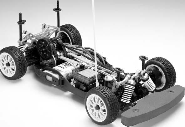
7 6 7 BATTERY CHARGING. Mke sure tht the ttery pck is completely dischrged prior to chrging. Dischrging the ttery pck y running the electric motor until it slows down or using dischrger(not included).. For est results, let the ttery pck cool efore chrging. Het my prevent the ttery pck from chrging to full cpcity nd lso decreses the performnce of the ttery. c. Once the ttery is redy to e chrged, first plug the AC quick chrger into the outlet of AC power source, nd then connect the ttery input/output hrness to the chrger. d. Continue to monitor the ttery s it is eing chrged. As soon s the ttery is fully chrged, disconnect the ttery. from the chrger plug(over-chrging or chrging incorrectly using indequte chrgers my cuse the ttery pck to ecome dngerously hot.) RIDE HEIGHT (or DROOP) ADJUSTMENT Ride height ( or Droop ) is the distnce from the ground to the ottom of the chssis. By removing or instlling the pre-lod spring clips, the distnce cn e decresed or incresed to dpt to the different terrins. Bsiclly, rough surfce will need higher ride height. MAINTENANCE AFTER RUNING. Alwys turn off the rdio system nd unplug the ttery pck when not using the truck.. Remove the snd, dirt, nd ny other elements completely from the truck efore you store it. c. Never use chemicls or ny solvents to clen the chssis s it my cuse dmge to the electronics components nd plstic prts s well. Use compressed ir, soft pintrush, or toothrush to clen dust nd dirt. HOP-UPS Thunder Tiger is plesed to inform our customers tht you don't need to wit for long-term developed optionl prts nymore. Thunder Tiger lso offers you the chnce to turn your truck in "Fctory" version! Thunder Tiger offers series of optionl prts for your pprecitive choosing. It's much more durle, fithful nd perfect fitting thn ny other ftermrket hop-up prts mde for your mighty truck. Plese contct your hoy shop for more exciting product informtion from Thunder Tiger. * Aluminum. Oil-Filled Shock Asorers * Competition High Power Motor * Competition Mini ESC nd Receiver * High Torque Micro Servo 6

8
MPC COBRA SERIES. Manually Programmable Cylindrical Lock D
 51120-D MPC COBRA SERIES Mnully Progrmmle Cylindricl Lock 575 Birch Street Forestville, CT 06010 technicl support: 866-322-1237 fx: 866-322-1233 http://www.irsupport.net 57010-H 12-19-2005 Introduction
FUEL SYSTEM. Table of Contents. Section 3B - Carburetors
 Tle of Contents FUEL SYSTEM Section 3B - Cruretors CARBURETORS Fuel System - Trouleshooting.............. 3B-2 Generl Informtion.................... 3B-2 Attenutor And Cr Throttle Levers......... 3B-4
UPS Pure Sinewave UPS
 UPS Pure Sinewve UPS USR S MANUAL 1.6K / 3.2K / 5KVA 6.4K / 8K/ 10KVA 1. INTRODUCTION 1. 1.1 Generl Description This UPS, powerful ll-in-one solution, delivers unsurpssed clen true sine wve output power
Carl Nielsen Music is Life. SET UP MANUAL Travelling Exhibition from Odense City Museums DK-5000 Denmark
 Crl Nielsen Music is Life SET UP MNUL Trvelling Exhiition from Odense City Museums DK-5000 Denmrk CONTENT IN FLIGHTCSES CRL NIELSEN TOURING EXHIITION ODENSE CITY MUSEUMS KVORNING DESIGN & COMMUNICTION,
CORD/CORDLESS CLIPPER INSTRUCTIONS
 CORD/CORDLESS CLIPPER INSTRUCTIONS Plese red ll instructions crefully to fmilirise yourself with your new clipper efore using. Sve these instructions for further reference. For ny further ssistnce or informtion
Spark Plug Fouling 3.0 Liter OptiMax
 WARRANTY INFORMATION PARTS INFORMATION SERVICE INFORMATION Bulletin No. 2002-07 Circulte to: Sles Mnger Accounting Service Mnger Technicin Prts Mnger Sprk Plug Fouling 3.0 Liter OptiMx Models Affected
FUEL SYSTEM. Section 3A Pulse Crankcase Driven Fuel Pump. Model 200/225 DFI. 1. Fuel Pressure/Vacuum Gauge (0-15 psi) (Obtain Locally)
 (Obtain Locally)") FUEL SYSTEM Section 3A Pulse Crnkcse Driven Fuel Pump Tle of Contents Specifictions................................ 3A-1 Specil Tools................................ 3A-1 Fuel Pump..................................
FUEL SYSTEM Section 3A Pulse Crnkcse Driven Fuel Pump Tle of Contents Specifictions................................ 3A-1 Specil Tools................................ 3A-1 Fuel Pump..................................
ELECTRICAL SYSTEM 4 D INSTRUMENTATION
 ELECTRICAL SYSTEM 4 D 72747 INSTRUMENTATION Tle of Contents Pge Identifiction............................. 4D-1 Specil Informtion....................... 4D-1 Lighting Options....................... 4D-1
FUEL SYSTEM. Table of Contents. Section 3C Oil Injection
 Tle of Contents FUEL SYSTEM Section 3C Oil Injection OIL INJECTION Specil Tools................................ 3C-2 Oil System Opertion......................... 3C-2 Oil Pump Output..........................
Suspension Control Module
 User Mnul Suspension Control Module 0099 Before Instlltion Wrning: This owering Module should be instlled by n individul with extensive knowledge in electronics, including: wire identifiction, extrcting
Transmission and Driveline. Section 2A - Transmission and Driveline
 Trnsmission nd Driveline Trnsmission nd Driveline Tle of Contents Section 2A - Trnsmission nd Driveline 2 A Generl Informtion...2A-2 Ger Rtio Selection...2A-2 Engine nd Propeller Shft Instlltion Angle...2A-2
ELECTRICAL AND IGNITION
 ELECTRICAL AND IGNITION 2 D TIMING/SYNCHRONIZING/ADJUSTING 2D- 1 Tle Of Contents Pge Timing/Synchronizing/ Adjusting............................ 2D-1 Specifictions........................ 2D-1 Specil Tools.........................
SERVICE MANUAL HWH TOUCH PANEL-CONTROLLED 325 SERIES HYDRAULIC LEVELING SYSTEM. FEATURING: Touch Panel Leveling Control
 R SERVICE MNUL HWH TOUCH PNEL-CONTROLLED 25 SERIES HYDRULIC LEVELING SYSTEM R HWH CORPORTION R FETURING: Touch Panel Leveling Control R I-XIS Hydraulic Leveling (With or Without ir Dump) HWH HYDRULIC LEVELING
@ ECV Technical Data High Lift Pallet Truck. ECV 10 C ECV 10i C ECV 10
 @ ECV Technicl Dt High Lift Pllet Truck ECV 10 C ECV 10i C ECV 10 Lifting Mde Esy This specifiction sheet to VDI Guideline 198, only provides the technicl vlues for the stndrd truck. Different tyres, other
Application Examples of Air-piloted Valves
 ir-piloted Vlves Fetures Since the unit requires ir piping only, with no need for electricl wiring, it cn e hndled y person without fer of electricl shocks or current lekge. Using no electricity mens tht
INSTALLATION GUIDE INSTALLATION GUIDE
 INSTALLATION GUIDE INSTALLATION GUIDE CONTACT US By selecting Hiku fn, you ve chosen qulity design, heightened comfort nd effortless conservtion. Use this guide to sfely instll your fn. Plese contct us
AmeriGlide Powered Stair Climber OWNER S MANUAL
 AmeriGlide Powered Stir Climer OWNER S MANUAL (To Be Retined y Owner) 2 IMPORTANT Ensure tht only n uthorized AmeriGlide Deler services the AmeriGlide Powered Stir Climer. Under no circumstnces is nyone
ELECTRICAL AND IGNITION 2 A IGNITION SYSTEM
 ELECTRICAL AND IGNITION 2 A IGNITION SYSTEM 54637 Tle of Contents Pge Ignition System.......................... 2A-1 Description........................... 2A-1 Ignition Trouleshooting...................
Lincoln Under-cabinet Light Installation Instructions
 Lincoln Under-cbinet Light Instlltion Instructions #1500178 Rev A Congrtultions on your new Lincoln Under-cbinet Light! Whether purchsed for its significnt energy svings nd efficiency, lower lifetime costs,
DPST-NO None 2 channels Auto-reset Inverse 24 VAC/VDC G9SB-2002-A 4 1 channel or 2
 Sfety Rely Unit Ultr Slim Sfety Rely Unit Models of width 17.5 mm vilble with 2 or 3 poles. Models of width 22.5 mm with 3 poles lso vilble. Conforms to EN stndrds. (TÜV pprovl) DIN trck mounting possible.
CCD-493 KIT SERIES INSTRUCTION SHEET
 (COMPLETE CCD-493-W KIT ILLUSTRTED. CUT-OUTS IN TRCK TO EXPOSE COMPONENTS) CCD-493 KIT SERIES INSTRUCTION SHEET CROWDERTRCK S CTCH N CLOSE TM SYSTEM PREVENTS BOUNCING ND SLMMING OF SLIDING S. CN BE INSTLLED
2190DF / 2575DF / 2700DF / 2702DF FIRE THEFT SAFE WITH DIGITAL LOCK. Operation and Installation Guide. MANUAL # M
 Opertion nd Instlltion Guide 2190DF / 2575DF / 2700DF / 2702DF MANUAL # M08-0284-004 www.firstalert.com FIRE THEFT SAFE WITH DIGITAL LOCK ELECTRONIC LOCK THEFT FIRE Cj de llves MANUAL # M08-0284-004 Overview
2/2 4/4 Solenoid Directional Seat Valve, ISO Size 03
 2/2 4/4 Solenoid Directionl Set Vlve, ISO Size 03 Q mx = 20 l/min, p mx = 315 r idirectionl set-vlve shut-off, direct cting, electriclly operted 1 Description he W2N / W2 series of 2/2 4/4 solenoid operted
FUEL SYSTEM. Table of Contents. Section 3B - Carburetors. Attenuator And Carb Throttle Levers... 3B-2 Fuel Lines... 3B-4
 Tle of Contents FUEL SYSTEM Section 3B - Cruretors CARBURETORS Attenutor And Cr Throttle Levers....... 3B-2 Fuel Lines.............................. 3B-4 Cruretor............................. 3B-6 Fuel
CC-410 KIT SERIES INSTRUCTION SHEET
 (COMPLETE CC-410-W KIT ILLUSTRTED. CUT-OUTS IN TRCK & FSCI TO EXPOSE COMPONENTS) CC-410 KIT SERIES INSTRUCTION SHEET CROWDERTRCK S CTCH N CLOSE TM SYSTEM PREVENTS BOUNCING ND SLMG OF SLIDING DOORS. CN
CORPORATION CORPORATION SERVICE MANUAL FOR MOTORIZED VEHICLES 200/210 SERIES HYDRAULIC LEVELING SYSTEM SPACEMAKER ROOM EXTENSION SYSTEMS
 HW CORPORTION W CORPORTION H R SERVICE MNUL FOR MOTORIZED VEHICLES 200/210 SERIES HYDRULIC LEVELING SYSTEM SPCEMKER ROOM EXTENSION SYSTEMS R FETURING: Dual Cylinder "Rail" Room Extension (With Synchronizing
product could cease to function properly
 CUTION: dult ssembly Required. Hardware contains small screws with sharp points. Keep unassembled parts out of reach of small children. USE ND MINTENNCE: -Use on level surfaces only -Please check assembly
AltRider LLC. Enjoy it, show it off, and most of all, RIDE IT! Venture On, Jeremy LeBreton. Triumph Tiger Explorer 1200 Crash Bars.
 AltRider Crsh Brs for the Triumph Tiger Explorer 00 INSTALLATION INSTRUCTIONS Der Rider, Thnk you for choosing AltRider! Whether sesoned world dventurer or first time ADV-Newie, we welcome you to the AltRider
Safety Relay Unit. Ordering Information. Ultra Slim Safety Relay
 Sfety Rely Unit Ultr Slim Sfety Rely Unit Models of width 17.5 mm (smllest Unit in the world s of Jnury 2001) vilble with 2 or 3 poles. Models of width 22.5 mm with 3 poles lso vilble. EN stndrds (TÜV
SERVICE MANUAL HWH TOUCH PANEL-CONTROLLED 625 SERIES HYDRAULIC LEVELING SYSTEM. FEATURING: Touch Panel Leveling Control
 SERVICE MNUL HWH TOUCH PNEL-CONTROL SERIES HYDRULIC LEVELING SYSTEM R HWH CORPORTION R FETURING: Touch Panel Leveling Control R I-XIS Hydraulic Leveling (Without Dump) (With Dump) (With Pilot Dump) R HWH
CORPORATION SERVICE MANUAL FOR MOTORIZED VEHICLES 200 SERIES HYDRAULIC LEVELING SYSTEM SPACEMAKER ROOM EXTENSION SYSTEMS
 HWH R CORPORTION SERVICE MNUL FOR MOTORIZED VEHICLES 200 SERIES HYDRULIC LEVELING SYSTEM SPCEMKER SYSTEMS R FETURING: Dual Cylinder "Rail" Room Extension (With Rack Sensing Valve) Single Cylinder Room
ELECTRICAL. Table of Contents. Specifications. Section 2B - Battery Charging System and Starting System. Starter Draw (Under Load)
") ELECTRICAL Section 2B - Bttery Chrging System nd Strting System Tle of Contents Specifictions........................... 2B-1 Specil Tools........................... 2B-2 Bttery Chrging System Description......
ELECTRICAL Section 2B - Bttery Chrging System nd Strting System Tle of Contents Specifictions........................... 2B-1 Specil Tools........................... 2B-2 Bttery Chrging System Description......
Solenoid Operated Proportional Directional Control Valve (with Pressure Compensation, Multiple Valve Series)
") Solenoid Operted Proportionl Directionl Control Vlve (with Pressure Compenstion, Multiple Vlve Series) Hydrulic circuit (Exmple) v Fetures hese stcking type control vlves show pressure compensted type
Solenoid Operted Proportionl Directionl Control Vlve (with Pressure Compenstion, Multiple Vlve Series) Hydrulic circuit (Exmple) v Fetures hese stcking type control vlves show pressure compensted type
Reproduction. Not for OPERATOR S MANUAL. Snowthrower ATTACHMENT. 47 Two Stage
 ATTACHMENT OPERATOR S MANUAL 47 Two Stge Snowthrower Mfg. No. Description 1694404 47 Two Stge Snowthrower (for use with Legcy LX / 2000 / 2900 Series) 1725463 Rev. F 2 Tle of Contents Hrdwre / Prts Identifiction...
OPERATOR S MANUAL HWH TOUCH PANEL-CONTROLLED LEVELING SYSTEM 310 SERIES SPACEMAKER ROOM EXTENSION SYSTEM FEATURING:
 HCORPORTIONH W R OPERTOR S MNUL HWH TOUCH PNEL-CONTROLLED LEVELING SYSTEM 310 SERIES SPCEMKER ROOM EXTENSION SYSTEM FETURING: TOUCH PNEL LEVELING CONTROL HYDRULIC LEVELING UTOMTIC SUSPENSION IR DUMP STRIGHT-CTING
BMW K1600 GT / GTL Engine Protection Bars INSTALLATION INSTRUCTIONS
 mde in USA BMW K00 GT / GTL Engine Protection Brs INSTALLATION INSTRUCTIONS The most up to dte instructions cn e downloded from the product pge t ltrider.com, under the instructions t. Der Rider, Thnk
Large Pastel Kitchen
 Please retain this information for future reference PRTS LIST ssembly Instructions Item #53181 To order replacement parts, please visit 3 7 1 2 4 6 5 14 8 10 11 12 13 15 16 17 24 25 28 33 9 34 35 36b Pink
STERLING POWER PRODUCTS
 STERLING POWER PRODUCTS ALTERNATOR - to - BATTERY CHARGER Advnced chrging technology AB0 AB0 AB0 AB0 Pro Digitl REMOTE CTROL (OPTI) Bttery-Bttery Chrger on/off. V timer 0. A min lrm light Alrm shutdown
FRONT SIDE FIX WINDOW
 WINSHIEL/WINOWGLSS/MIRROR FRONT SIE FIX WINOW REPLEMENT FRONT SIE FIX WINOW The instlltion procedures re the removl procedures in reverse order. However, only instlltion procedures requiring dditionl informtion
ELECTRICAL. Table of Contents. Section 2A - Ignition
 Tble of Contents Specifictions........................... A- Specil Tools........................... A- Flywheel............................... A- Flywheel............................... A-5 Electricl
Chelsea Doll Cottage
 Please retain this information for future reference HRWRE ssembly Instructions PRTS LIST Item #65054 To order replacement parts, please visit www.kidkraft.com 2 1 3 4 5 6 9 7 10 14 15 11 13 17 12 1 19
REPLACEMENT. 4. REMOVE WINDSHIELD MOULDING OUTSIDE (a) Using a knife, cut off the moulding, as shown in the illustration.
 Using a knife, cut off the moulding, as shown in the illustration.") 7012 REPLCEMENT The instlltion procedures re the removl procedures in reverse order. However, only instlltion procedures requiring dditionl informtion re included. 1. REMOVE ROOF HEDLINING SSY (See pge
7012 REPLCEMENT The instlltion procedures re the removl procedures in reverse order. However, only instlltion procedures requiring dditionl informtion re included. 1. REMOVE ROOF HEDLINING SSY (See pge
KING COBRA/KING COBRA-2 NARROW STILE SERIES KC9357/KC9357-2
 KING COBRA/KING COBRA-2 NARROW STILE SERIES KC9357/KC9357-2 Keypd Progrmmble nd SNAP Comptible Trim For Rim Exit Devices Mounted On Aluminum Doors. 57047-B 04-2007 Contents of the Box KC9357/KC9357-2 INSTALLATION
FUEL SYSTEM. Section 3A - Carburetor/Fuel Pump
 Tle of Contents FUEL SYSTEM Section 3A - Cruretor/Fuel Pump CARBURETOR/FUEL PUMP Specifictions................................ 3A-1 Specil Tools................................ 3A-1 Cruretor (20/25/JET
POWER TRIM. Table of Contents. Section 5D - Auto Trim II
 SERVICE MANUAL NUMBER 11 Tble of Contents POWER TRIM Section 5D - Auto Trim II AUTO TRIM II Auto Trim II System................... 5D-2 Description........................ 5D-2 Auto Trim II Opertion.................
POWER TRIM. Table of Contents. Section 5D - Auto Trim II
 SERVICE MANUAL NUMBER 14 Tble of Contents POWER TRIM Section 5D - Auto Trim II AUTO TRIM II 1 B Auto Trim II System................. 5D-2 Description...................... 5D-2 Auto Trim II Opertion...............
Electrical. Section 2A - Ignition
 Electricl Ignition Tle of Contents Section 2A - Ignition 2 A Ignition Specifictions...2A-2 Electricl Components...2A-4 Ignition Components...2A-8 Ignition Description...2A-12 Crnk Position Sensor...2A-12
Solenoid Pilot Operated Directional Control Valve
 Contct Detils efore using the product, plese check the guide pges t the front of this ctlog. http://www.dikinpmc.com/en/ For ltest informtion, DF ctlogs nd opertion mnuls Solenoid ilot Operted Directionl
CCS-810 KIT SERIES INSTRUCTION SHEET
 (COMPLETE KIT ILLUSTRTED. CUT-OUTS IN TRCK & FSCI TO EXPOSE COMPONENTS) CCS-810 KIT SERIES INSTRUCTION SHEET CROWDERTRCK S CTCH N CLOSE TM SYSTEM PREVENTS BOUNCING ND SLMMING OF SLIDING DOORS. CN BE INSTLLED
ELECTRICAL. Table of Contents. Specifications. Section 2B Charging & Starting System
 ELECTRICAL Section 2B Chrging & Strting System Tle of Contents Specifictions........................... 2B-1 Specil Tools........................... 2B-2 Bttery Cle Size...................... 2B-3 Replcement
MODU System. About MODU
 Contents Introduction... 3 Aout This Instlltion Mnul... 3 Preprtion for Instlltion... 3 Generl Tools... 4 Cutting Bems... 7 Assemly... 8 MODU System Component Groups... 8 Foot Mounting... 9 1.0 Mounting
JET PUMP. Table of Contents. Section 5 - Jet Pump
 Tble of Contents JET PUMP Section 5 - Jet Pump JET PUMP Generl Informtion..................... 5-2 Principles of Opertion................ 5-2 Mster Specifictions Jet Pump........... 5-3 Specil Tools........................
FUEL SYSTEM. Table of Contents. Section 3A - Carburetor/Fuel Pump. Specifications... 3A-2 Special Tools... 3A-2
 Tle of Contents FUEL SYSTEM Section 3A - Cruretor/Fuel Pump CARBURETOR/FUEL PUMP Specifictions........................... 3A-2 Specil Tools........................... 3A-2 Notes:.................................
Owner s Manual For Model 548 Floor Crane ORIGINAL TEXT
 Red this Owner s Mnul thoroughly efore operting the equipment. Keep it with the equipment t ll times. Replcements re ville from Thern, Inc., PO Box 347, Winon, MN 55987, 507-454-2996. www.thern.com IMPORTANT:
* * * DIEBOLD 3700 LOBBY CASH RECYCLER- FRONT LOAD 15" DISPLAY OR 19" DISPLAY CONSUMER ACCESS DIMENSIONS PLAN VIEW 19" DISPLAY FRONT ELEVATION
 R L CLL -0--600 64 SFE ( 6 ") DIEBOLD 00 LOBBY CSH RECYCLER- FRONT LOD " DISPLY OR " DISPLY WITH mm ( ") UL SFE CONSULT WITH DIEBOLD INSTLLTION/SERVICE BRNCH FOR DDITIONL DETILS ND INFORMTION. PLESE SEE
FUEL SYSTEM & CARBURETION 3 A CARBURETOR R1 JUNE 1996 FUEL SYSTEM AND CARBURETION
 FUEL SYSTEM & CARBURETION 3 A CARBURETOR 90-831996R1 JUNE 1996 FUEL SYSTEM AND CARBURETION 3A- 1 Tle Of Contents Pge Removing Cruretor..................... 3A-1 Disssemling Cruretor................. 3A-1
Specifiable Features. Compatible with all UL 1686 listed plugs and receptacles. Type P Cable. Lockout Compliant. PowerMate Features and Benefits
 PowerMte Fetures nd Benefits Type P Cle Lockout Complint Specifile Fetures Lockout Plug Sfety Insultor Dimond Clmp Split Pin Contcts Type P Cle Comptile with ll UL 686 listed plugs nd receptcles. 2 3 4
PACK CONTENTS & FITTING INSTRUCTIONS FOR ANCHOR POINT FITMENT
 PACK CONTENTS & FITTING INSTRUCTIONS FOR ANCHOR POINT FITMENT Cequent, division of Horizon Glol Pty Ltd 49 Pcific Drive, Keysorough, VIC, 3173 Phone: 1800 812 017 www.rol.com.u For Vehicle Comptility Guide
DIEBOLD 5550 CASH DISPENSER THROUGH 330mm (13") MAXIMUM WALL PLAN VIEW FRONT ELEVATION SIDE ELEVATION CONSUMER ACCESS DIMENSIONS
 MAXIMUM WALL PLAN VIEW FRONT ELEVATION SIDE ELEVATION CONSUMER ACCESS DIMENSIONS") L0 CLL -800--600 R DIEBOLD 0 CSH DISPENSER THROUGH 0mm (") MXIMUM WLL mm ( " ) UL CONSULT WITH DIEBOLD INSTLLTION/SERVICE BRNCH FOR DDITIONL DETILS ND INFORMTION. PLESE SEE PLNNING ND SITE PREPRTION GUIDE
L0 CLL -800--600 R DIEBOLD 0 CSH DISPENSER THROUGH 0mm (") MXIMUM WLL mm ( " ) UL CONSULT WITH DIEBOLD INSTLLTION/SERVICE BRNCH FOR DDITIONL DETILS ND INFORMTION. PLESE SEE PLNNING ND SITE PREPRTION GUIDE
2/2 Solenoid Operated Seat Valve, ISO Size 03
 2/2 Solenoid Operted Set Vlve, ISO Size 03 Q mx = 40 l/min (11 gpm), p mx = 315 r (4500 psi) Sndwich design, idirectionl lek-proof shutoff, direct cting, electriclly operted 1 Description 2 echnicl dt
CORDLESS POLE PRUNER HEAD INSTRUCTION MANUAL
 WHAT S IN THE BOX Pruner Hed CORDLESS POLE PRUNER HEAD INSTRUCTION MANUAL SPECIFICATIONS Voltge: Br Length: Cutting Length Mx.: Chin Speed: Oil Tnk Cpcity: Weight: ozito.com.u 18V 200mm 170mm 3.76m/s 125ml
1/8 4WD OFF-ROAD, PRO VERSION COMPETITION BUGGY
 1/8 4WD OFF-ROAD, PRO VERSION COMPETITION BUGGY Due to ongoing R&D, items pitured my not mth ext kit omponents No.6226-F Thunder Tiger Corportion gurntees this model kit to e free from defets in oth mteril
Designed for. Irismo & Glydea SOLUTIONS FOR MOTORIZED DRAPERIES Irismo 45 WireFree RTS Irismo 35 Mini DC Glydea 35e Glydea 60e.
 Designed for Irismo & Glyde SOLUTIONS FOR MOTORIZED DRAPERIES Irismo 45 WireFree RTS Irismo 35 Mini DC Glyde 35e Glyde 60e convenience IRISMO AND GLYDEA EXPANDS YOUR OPPORTUNITIES Tody, drpery motoriztion
Arcadia ssembly Instructions. 501x363x242cm / 16 5"Lx11 103/4"x7 111/4"
 A ssemly Instructions Arcdi 5000 English_71087 501x36342cm / 16 5"Lx11 103/4"x7 111/4" Compny informtion: Plrm Americs Inc. 9735 Commerce Prkwy Kutztown, PA, USA Service Center: Toll Free: (877) 627-8476
INSTALLATION, OPERATION & PARTS
 Snd Filters Item #s 6590, 6591 & 6592 INSTALLATION, OPERATION & PARTS WARNING This equipment must e instlled nd serviced y qulified technicin in ccordnce with ll pplicle codes nd ordinnces. Improper instlltion
Convenience electronics
 Convenience electronics Displys on "opening" the roof To gurntee high level of sfety, roof movement is ccompnied, depending on the equipment vrint, y opticl, coustic nd/or text displys/indictions. The
2/2 4/4 Solenoid Directional Seat Valve, ISO Size 03
 2/2 4/4 Solenoid Directionl Set Vlve, ISO Size 03 Q mx = 40 l/min (11 gpm), p mx = 315 r (4500 psi) idirectionl lek-proof shutoff, direct cting, electriclly operted Series W2N, W2 1 Description With crtridge
FINGER STRIPS. and other EMI shielding products. Characteristics
 BERYLLIUM COPPER CONTCT FINGER STRIPS nd other EMI shielding products ppliction Due to their outstnding mteril nd electricl chrcteristics, eryllium copper fingers of different shpes nd dimensions re used
3700 LOBBY CASH RECYCLER. REAR LOAD 13mm ( 2") UL SAFE - 15" DISPLAY OR 19" DISPLAY WITH DETAILS FOR OPTIONAL VESTIBULE INSTALLATION
 UL SAFE - 15 DISPLAY OR 19 DISPLAY WITH DETAILS FOR OPTIONAL VESTIBULE INSTALLATION") R L CLL -0--600 64 SFE ( 6 ") DIEBOLD 00 LOBBY CSH RECYCLER RER LOD mm ( ") UL SFE - " DISPLY OR " DISPLY WITH DETILS FOR OPTIONL VESTIBULE INSTLLTION CONSULT WITH DIEBOLD INSTLLTION/SERVICE BRNCH FOR
R L CLL -0--600 64 SFE ( 6 ") DIEBOLD 00 LOBBY CSH RECYCLER RER LOD mm ( ") UL SFE - " DISPLY OR " DISPLY WITH DETILS FOR OPTIONL VESTIBULE INSTLLTION CONSULT WITH DIEBOLD INSTLLTION/SERVICE BRNCH FOR
Exhaust System. Table of Contents. Section 7A - General Information. General Information
 Exhust System Generl Informtion Tle of Contents Section 7A - Generl Informtion Generl Informtion All Models... 7A-2 Exhust System Notice...7A-2 Reference Note...7A-2 Exhust System Connections...7A-2 Through
FUEL SYSTEM. Table of Contents. Section 3B - Fuel Injection
 Tle of Contents FUEL SYSTEM Section 3B - Fuel Injection FUEL INJECTION Specifictions........................... 3B-2 Specil Tools........................... 3B-3 Notes:.................................
X3-40/X3-45/X3-55/X Mercury Marine. Operation Maintenance Installation Warranty Manual
 X3-40/X3-45/X3-55/X3-70 2017 Mercury Mrine Opertion Mintennce Instlltion Wrrnty Mnul EU Complince Sttement Attwood Corportion hereby declres tht the MotorGuide X3 trolling motor is in complince with the
PLEASE READ THIS IMPORTANT CONTACT INFORMATION:
 PLESE RED THIS IMPORTNT CONTCT INORMTION: This product is brought to you by Jellybean urniture, an ustralian importer of quality furniture products. This product may also be available in other countries,
CS 7780 FULL FUNCTION DRIVE-UP TERMINAL
 L CLL -800--600 CS 80 FULL FUNCTION DRIVE-UP TERMINL mm ( ") UL - "or " DISPLY THROUGH 0mm (8") MXIMUM WLL CONSULT WITH DIEBOLD NIXDORF INSTLLTION/SERVICE BRNCH FOR DDITIONL DETILS ND INFORMTION. PLESE
* * * 3700 LOBBY CASH RECYCLER. REAR LOAD 13mm ( 2") UL SAFE - 15" DISPLAY OR 19" DISPLAY WITH DETAILS FOR OPTIONAL VESTIBULE INSTALLATION
 UL SAFE - 15 DISPLAY OR 19 DISPLAY WITH DETAILS FOR OPTIONAL VESTIBULE INSTALLATION") R L CLL -0--600 64 SFE ( 6 ") DIEBOLD 00 LOBBY CSH RECYCLER RER LOD mm ( ") UL SFE - " DISPLY OR " DISPLY WITH DETILS FOR OPTIONL VESTIBULE INSTLLTION CONSULT WITH DIEBOLD INSTLLTION/SERVICE BRNCH FOR
R L CLL -0--600 64 SFE ( 6 ") DIEBOLD 00 LOBBY CSH RECYCLER RER LOD mm ( ") UL SFE - " DISPLY OR " DISPLY WITH DETILS FOR OPTIONL VESTIBULE INSTLLTION CONSULT WITH DIEBOLD INSTLLTION/SERVICE BRNCH FOR
MANN+HUMMEL Oil-bath air cleaner Single-stage air cleaner without spare parts
 MANN+HUMMEL Oil-th ir clener Single-stge ir clener without spre prts 57 Oil-th ir clener: Servicing without spre prts The proven oil-th ir cleners from MANN+HUMMEL re suitle for light to medium dust conditions
Two-Position Electric Duplex Room Thermostats
 TC-xx Series, TC-xx Series, TF- Series Two-Position Electric Duplex Room Thermostts These thermostts provide on-off control of heting/cooling systems. Fetures: Seprte units for C nd F. All units except
DIEBOLD 3750 CASH RECYCLER TERMINAL. 13mm ( 2") UL SAFE - 15" OR 19" DISPLAY THROUGH THE WALL 330mm (13") PLAN VIEW FRONT ELEVATION SECTION
 UL SAFE - 15 OR 19 DISPLAY THROUGH THE WALL 330mm (13) PLAN VIEW FRONT ELEVATION SECTION") L8 CLL -800--600 R DIEBOLD 0 CSH RECYCLER TERMINL mm ( ") UL SFE - " OR " DISPLY THROUGH THE WLL 0mm (") 64 SFE ( 6 ") CONSULT WITH DIEBOLD INSTLLTION/SERVICE BRNCH FOR DDITIONL DETILS ND INFORMTION. PLESE
L8 CLL -800--600 R DIEBOLD 0 CSH RECYCLER TERMINL mm ( ") UL SFE - " OR " DISPLY THROUGH THE WLL 0mm (") 64 SFE ( 6 ") CONSULT WITH DIEBOLD INSTLLTION/SERVICE BRNCH FOR DDITIONL DETILS ND INFORMTION. PLESE
IGNITION SYSTEM SERVICE MANUAL NUMBER
 IGNITION SYSTEM SERVICE MANUAL NUMBER 26 Specifictions Timing Timing (At Idle rpm) 1 1 BTDC 2 / 1 ATDC 3 / 2 ATDC 4 1 Timing must be set using specil procedure s outlined in this section. Timing cnnot
FUEL SYSTEM. Table of Contents. Section 5C - Injection Pump
 SERVICE MANUAL NUMBER 34 Tle of Contents FUEL SYSTEM Section 5C - Injection Pump INJECTION PUMP Identifiction........................ 5C-2 Specifictions....................... 5C-3 Pump...........................
Electrically operated directional spool valve with a soft-shift function type WE10P NS 10. up to 35 MPa up to 120 DATA SHEET - OPERATION MANUAL
 LICTION Electriclly operted directionl spool vlve with soft-shift function type WE10 NS 10 Electriclly operted directionl spool vlve type WE10 is intended for chnging the direction of fluid flow in hydrulic
CAUTION INDEX INTRODUCTION 2 IMPORTANT NOTES & WARNING 3 ITEMS REQUIRED FOR OPERATION 4
 INTRODUCTION Thnk you for purhsing the Thunder Tiger ER-1 Nitro Powered 4WD All Rod Cr. Thunder Tiger strives to ring you the highest level of qulity nd servie we n provide. We re nd test our produts round
Press control block PSB Type approved according to DIN EN 693
 Press control lock PS Type pproved ccording to DIN EN 693 Description The press control locks PS in the nominl sizes 06 nd 0 re modulr control locks with EC type pprovl for use in hydrulic presses ccording
SAFETY TIPS RACE ON/OFF ROAD ALIGNMENT ADJUSTMENT QUICK TIPS LET S GET STARTED! CONTENTS PAIR THE CONTROLLER AND VEHICLE FEATURES BATTERY INSTALLATION
 Press nd hold RACE N/FF RAD Your BALLSTK RACER cn hndle lmost ny terrin! Experiment see wht surfces re est for rcing nd stunting. SAFETY TPS SAFETY NFRMATN RECHARGEABLE SAFETY NFRMATN WARNNG: Red ll sfety
WINDSHIELD / WINDOWGLASS
 WINSHIEL / WINOWGLSS QURTER WINOW GLSS QURTER WINOW GLSS OY WINSHIEL / WINOWGLSS OMPONENTS 97 RER SIE SETK FRME LH RER SIE SETK FRME RH RER SET USHION SSEMLY RER OOR OPENING TRIM WETHERSTRIP LH TONNEU
DIEBOLD 3700 LOBBY CASH RECYCLER- FRONT LOAD 15" DISPLAY OR 19" DISPLAY CEN I, CEN III GAS, CEN IV GAS or CEN IV GAS EX SAFES
 R L CLL -0--600 64 SFE ( 6 ") DIEBOLD 00 LOBBY CSH RECYCLER- FRONT LOD " DISPLY OR " DISPLY CEN I, CEN III GS, CEN IV GS or CEN IV GS EX SFES CONSULT WITH DIEBOLD INSTLLTION/SERVICE BRNCH FOR DDITIONL
Installation and Operational Instructions for ROBA -slip hubs Sizes 0 12 (B.1.0.GB)
") Plese red these Opertionl Instructions crefully nd follow them ccordingly! Ignoring these Instructions my led to mlfunctions or to clutch filure, resulting in dmge to other prts. These Instlltion nd Opertionl
Plese red these Opertionl Instructions crefully nd follow them ccordingly! Ignoring these Instructions my led to mlfunctions or to clutch filure, resulting in dmge to other prts. These Instlltion nd Opertionl
SEE PAGES 3 AND 4 OF 7 FOR 3700 CASH RECYCLER THROUGH THE WALL WITH VESTIBULE TRIM KIT REFERENCE FRONT EDGE OF BEZEL FOR DEPTH DIMENSIONS
 R DIEBOLD 00 LOBBY CSH RECYCLER- RER LOD L2 CLL -0--600 64 SFE (2 6 ") 40mm ( 6") CEN I SFE - " DISPLY OR " DISPLY WITH DETILS FOR OPTIONL VESTIBULE INSTLLTION CONSULT WITH DIEBOLD INSTLLTION/SERVICE BRNCH
ABB industrial drives. Mechanical installation instructions ACS880 multidrive cabinets
 ABB industril drives Mechnicl instlltion instructions ACS880 multidrive cbinets List of relted mnuls Generl drive mnuls (in ll deliveries) Electricl plnning instructions for ACS880 multidrive cbinets nd
Teile und Zubehör - Einbauanleitung
 Teile und Zubehör - Einbunleitung F 36 0305 EVA Originl BMW Zubehör-Heckschürze BMW Z3 rodster (E 36/7) b 04/99 BMW Prts nd Accessories Instlltion Instruction Originl BMW ccessory rer pron BMW Z3 rodster
STANDARD AND FULL HEIGHT - REAR LOAD - WITH 40mm (1 16") CEN I, CEN III GAS or CEN IV GAS SAFES
 CEN I, CEN III GAS or CEN IV GAS SAFES") L STNDRD ND FULL HEIGHT - RER LOD - WITH 0mm ( 6") "LL DIMENSIONS ND DESIGN CRITERI PGE OF 8 FRONT - STNDRD HEIGHT SEE PGES and FOR CS 00 STNDRD HEIGHT DETILS FRONT - FULL HEIGHT SEE PGES and FOR CS 00
L STNDRD ND FULL HEIGHT - RER LOD - WITH 0mm ( 6") "LL DIMENSIONS ND DESIGN CRITERI PGE OF 8 FRONT - STNDRD HEIGHT SEE PGES and FOR CS 00 STNDRD HEIGHT DETILS FRONT - FULL HEIGHT SEE PGES and FOR CS 00
Directional spool valves, pilot-operated, with hydraulic or electro-hydraulic actuation
 Directionl spool vlves, pilot-operted, with hydrulic or electro-hydrulic ctution WEH nd WH RE 24751 Edition: 2016-06 Replces: 08.08 Size 10 32 Component series 4; 6; 7 Mximum operting pressure 350r [5076psi]
DC CONTACTOR. hubbell industrial controls, inc. Hubbell Industrial Controls, Inc. Type Ampere 1500 Volt DC Contactor
 Huell Industril Controls, Inc. 716 1600 Ampere 1500 Volt DC Contctor Ctlog 42716 Mrch 2013, Replces Septemer 2005 42716 Highlights Non-polrized rc chute (series lowout coil) design s stndrd Optionl polrized
330mm (13") MAXIMUM WALL THICKNESS IN AREA OF UNIT. 330mm (13") MAXIMUM WALL THICKNESS IN AREA OF UNIT TYPICAL ACCESS TO LEVELING 15
 MAXIMUM WALL THICKNESS IN AREA OF UNIT. 330mm (13) MAXIMUM WALL THICKNESS IN AREA OF UNIT TYPICAL ACCESS TO LEVELING 15") L CLL -800--600 R DIEBOLD 0 CSH DISPENSER THROUGH 0mm (") MXIMUM WLL 0mm ( 6" ) CEN I, CEN III GS, or CEN IV GS SFES CONSULT WITH DIEBOLD INSTLLTION/SERVICE BRNCH FOR DDITIONL DETILS ND INFORMTION. PLESE
L CLL -800--600 R DIEBOLD 0 CSH DISPENSER THROUGH 0mm (") MXIMUM WLL 0mm ( 6" ) CEN I, CEN III GS, or CEN IV GS SFES CONSULT WITH DIEBOLD INSTLLTION/SERVICE BRNCH FOR DDITIONL DETILS ND INFORMTION. PLESE
POWERHEAD. Section 4A - Cylinder Head. Rocker Shaft and Rocker Arm... 4A-21 Camshaft... 4A-22 Cylinder Head... 4A-24
 POWERHEAD Section 4A - Cylinder Hed CYLINDER HEAD Tle of Contents Specifictions........................... 4A-2 Specil Tools........................... 4A-4 Cylinder Hed.......................... 4A-6
4/2- and 4/3-directional spool valve solenoid-operated, direct-acting 4WE 6
 4/2- nd 4/3-directionl spool vlve solenoid-operted, direct-cting 4WE 6 DESCRIION HYDC 4/2- nd 4/3- directionl spool vlves of the 4WE 6 series re directionl vlves for oil hydrulic systems which re used
Please, let us help! Please, let us help! Please, let us help! Please, let us help!
 Experiencing problems with your new KidKraft product? efore getting frustrated and returning your product to the store or Internet retailer, please give us a chance to solve all your problems. Call our
Protection of Light Armours Against Shaped Charge Projectiles
 PROBLEMS OF MECHATRONICS. ARMAMENT, AVIATION, SAFETY ENGINEERING ISSN 2081 5891 2 (2), 2010, 17-25 Protection of Light Armours Aginst Shped Chrge Projectiles Adm WIŚNIEWSKI Militry Institute of Armment
DIESEL EGT GAUGE INSTALLATION INSTRUCTIONS P14D AA
 DIESEL EGT GUGE INSTLLTION INSTRUCTIONS P4D4-9235- Revision: - Dated 3/9/4 Replaces: None DIESEL EGT GUGE INSTLLTION HRDWRE CONTENTS P4D4-44- - DIESEL EGT GUGE KIT COMPONENT - DIESEL EGT GUGE SSY (PRT
AMP AIR SUSPENSION KITS. HP10193: Ford F-250/350 4WD* Ford F-450* HP10194: Ford F-250/350 2WD* Ford F-450*
 MP IR SUSPENSION KITS HP10193: Ford F-250/350 4WD* Ford F-450* HP10194: Ford F-250/350 2WD* Ford F-450* LL KITS FOR TRUCKS INCLUDING IN-ED HITCHES; NOT FOR USE WITH CHSSIS C TRUCKS * See application guide