Suspension Control Module
|
|
|
- Doris Logan
- 6 years ago
- Views:
Transcription
1 User Mnul Suspension Control Module 0099
2 Before Instlltion Wrning: This owering Module should be instlled by n individul with extensive knowledge in electronics, including: wire identifiction, extrcting nd inserting pins from connector housing. We re not responsible for ny dmge to the owering Module or relted devices due to improper instlltion. Ride eight: To retin proper ride comfort nd to void dmge to suspension components plese follow these minimum recommended height djustments: All non-amg Mercedes models should use setting of or higher. AMG crs re lower thn their Mercedes counterprts. With this in mind it is recommended tht AMG crs use ride height setting of or higher. ower settings cn be used for show purposes but re not recommended for everydy driving. In some models the door must be closed in order for the Airmtic or ABC system to operte. This is sfety function nd is norml on those vehicles. Technicl Support: For further informtion, plese contct
3 Before Instlltion chssis (M, G) [00+] chssis (R) [ll yers] Airmtic chssis (E) [00 till 0/00] 9 chssis (CS) [till 0/00] 0 chssis (S) [000 00] NOTE: vehicles with -wire level sensor Airmtic chssis (E) [00 from 0//00] 9 chssis (CS) [from 0/00] chssis (S) [00+] NOTE: vehicles with -wire level sensor Airmtic chssis (C) [00+] chssis (C) [00+] 0 chssis (S) [000 00] chssis (S) [00+] ABC 0 chssis (S) [00+] ABC 9 Ride eight Adjustment Vehicle's Connector Preprtion
4
5 chssis (M,G) Airmtic 00 + chssis (R) Airmtic ll yers Pin View Suspension Control Module Connector B/ eft Rer B/0 Right Rer R Rer RR Bttery CAN CAN CAN F RF B/9 Right Front B/ eft Front Not Used Not Used Not Used** Not Used** Remote Control Connector Mle pin View Bck View pin Connector Mle * * Ornge Gry White Blue Blue White Blck To Remote Control Connector To Suspension Control Module Connector A I R M A T I C Blck Gry 0 B/0 Right Rer B/ eft Rer * * CAN CAN + V GND B/9 Right Front B/ eft Front 0 *NOTE: Some vehicles of chssis my need these two (sets) pins reversed. If your vehicle rises the rer xle insted of lowering it, then swp these two wires nd there counterprts on the pin connector. (pin & ). **NOTE: Insulte ech unused wire end using electricl tpe Airmtic rness, Pin View

 with ADS INTO -PIN")
 Refer to Vehicle s Connector")

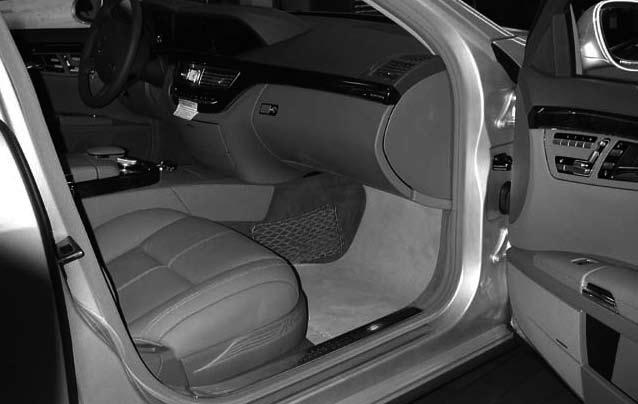
6 STEP-BY-STEP INSTAATION chssis: Airmtic (N) control unit eft front footwell (under the set) Disconnect the Bttery A I R M A T I C chssis: Airmtic (N) with ADS INTO -PIN CONNECTOR Bckview Right front footwell (under pssenger set) Refer to Vehicle s Connector Preprtion for pin removl - see pges -. INTO -PIN CONNECTOR * Bckview White INTO -PIN CONNECTOR * Bckview 9 0
7 INTO -PIN CONNECTOR Bckview 0 Gry 0 0 INTO -PIN CONNECTOR Bckview 0 Ornge mle bck view mle front view remote control A I R M A T I C INTO -PIN CONNECTOR Bckview mle bck view mle front view remote control - bttery INTO -PIN CONNECTOR - bttery Bckview mle bck view Blck Blck mle + bttery INTO -PIN CONNECTOR + bttery Bckview mle bck view mle 9 0 Unscrew the Suspension Module screws nd remove the cover Rotte the Function Switch (blck button) to position To continue, go to eight Adjustment chpter
8 -wire sensors A I R M A T I C B/ Rer B/ Rer chssis (E) Airmtic -wire sensors 00 till 0/00 9 chssis (CS) Airmtic -wire sensors till 0/00 0 chssis (S) Airmtic -wire sensors R Rer RR B/ Rer Bttery B/ Rer Airmtic rness, Pin View CAN CAN CAN CAN CAN F RF B/9 Right Front B/9 Right Front + V B/ eft Front B/ eft Front GND 0 Remote Control Connector 9 Mle pin View Bck View B/9 Right Front B/ eft Front 0 0 Pin View 9 0 Ornge 9 Blck 0 9 pin Connector Mle B/9 Right Front B/ eft Front 0 9 Gry White Blue White Blck Gry Blue Suspension Control Module Connector To Remote Control Connector To Suspension Control Module Connector
 with ADS Refer to Vehicle s")

9 STEP-BY-STEP INSTAATION Disconnect the Bttery Right front upper footwell Pull the crpet bck Unscrew bolts holding the luminum brcket Airmtic (N) with ADS Refer to Vehicle s Connector Preprtion for pin removl - see pges -. INTO -PIN CONNECTOR Bckview White -wire sensors A I R M A T I C INTO -PIN CONNECTOR Bckview INTO -PIN CONNECTOR Bckview Blue 9 0 9
10 -wire sensors A I R M A T I C 0 INTO -PIN CONNECTOR Bckview INTO -PIN CONNECTOR Bckview INTO -PIN CONNECTOR Bckview Blue 0 Gry 0 INTO -PIN CONNECTOR Bckview Ornge mle bck view mle front view remote control INTO -PIN CONNECTOR Bckview mle bck view mle front view remote control 9 0 0
11 - bttery + bttery Unscrew the Suspension Module screws nd remove the cover INTO -PIN CONNECTOR - bttery Bckview Rotte the Function Switch (blck button) to position mle bck view Blck To continue, go to eight Adjustment chpter INTO -PIN CONNECTOR + bttery Bckview mle bck view Blck mle 9 0 mle -wire sensors A I R M A T I C
12 chssis (E) Airmtic -wire sensors 00 from 0/00 9 chssis (CS) Airmtic -wire sensors from 0/00 Pin View Suspension Control Module Connector chssis (S) Airmtic -wire sensors wire sensors A I R M A T I C B/ Rer R Rer RR Bttery CAN CAN CAN F RF B/9 Right Front B/ eft Front Not Used Not Used Not Used Not Used* Not Used* Not Used* Remote Control Connector Mle pin View Bck View Ornge pin Connector Mle Gry Blue White White Blue Blck To Remote Control Connector To Suspension Control Module Connector Blck Gry 0 B/ Rer CAN CAN + V GND B/9 Right Front B/ eft Front *NOTE: Insulte ech unused wire end using electricl tpe Airmtic rness, Pin View


13 STEP-BY-STEP INSTAATION Disconnect the Bttery Right front upper footwell Pull the crpet bck Unscrew bolts holding the luminum brcket INTO -PIN CONNECTOR Bckview Airmtic (N) with ADS Refer to Vehicle s Connector Preprtion for pin removl - see pges -. -wire sensors A I R M A T I C INTO -PIN CONNECTOR Bckview 0 Gry 0 INTO -PIN CONNECTOR Bckview
14 INTO -PIN CONNECTOR Bckview Ornge mle bck view mle front view remote control -wire sensors A I R M A T I C - bttery + bttery INTO -PIN CONNECTOR Bckview mle bck view 9 0 INTO -PIN CONNECTOR - bttery Bckview mle bck view Blck mle front view remote control INTO -PIN CONNECTOR + bttery Bckview mle bck view Blck mle mle Unscrew the Suspension Module screws nd remove the cover Rotte the Function Switch (blck button) to position To continue, go to eight Adjustment chpter 9 0
15 chssis (C) ABC 00 + chssis (C) ABC 00 + Pin View Suspension Control Module Connector 0 chssis (S) ABC chssis (S) ABC R Rer Bttery F Remote Control Connector A B C B/ eft Rer B/0 Right Rer RR CAN CAN CAN RF B/9 Right Front B/ eft Front Not Used Not Used Not Used* Not Used* Mle pin View Bck View pin Connector Mle Ornge Gry White Blue Blue White Blck To Remote Control Connector To Suspension Control Module Connector Blck Gry 0 B/ eft Rer B/0 Right Rer CAN CAN + V GND B/ eft Front B/9 Right Front *NOTE: Insulte ech unused wire end using electricl tpe Airmtic rness, Pin View


16 STEP-BY-STEP INSTAATION Disconnect the Bttery chssis: ABC (N/) ctive body control Engine comprtment, left rer A B C chssis: ABC (N/) ctive body control Interior, right front upper footwell 0 chssis: ABC (N/) ctive body control Engine comprtment, left rer chssis: ABC (N/) ctive body control Shown on 0 S0 Interior, right front upper footwell Refer to Vehicle s Connector Preprtion for pin removl - see pges -.
17 INTO -PIN CONNECTOR Bckview INTO -PIN CONNECTOR Bckview White A B C INTO -PIN CONNECTOR Bckview 0 Gry INTO -PIN CONNECTOR Bckview INTO -PIN CONNECTOR Bckview Ornge mle bck view mle front view remote control 9 0 INTO -PIN CONNECTOR Bckview mle bck view mle front view remote control
18 A B C - bttery + bttery INTO -PIN CONNECTOR - bttery Bckview mle bck view Blck INTO -PIN CONNECTOR + bttery Bckview mle bck view Blck mle mle 9 0 Unscrew the Suspension Module screws nd remove the cover Rotte the Function Switch (blck button) to position To continue, go to eight Adjustment chpter
19 0 chssis (S) ABC 00 + Pin View Suspension Control Module Connector R Rer Bttery F Remote Control Connector A B C B/ eft Rer B/0 Right Rer RR CAN CAN CAN RF B/9 Right Front B/ eft Front Not Used Not Used Not Used** Not Used** Mle pin View Bck View pin Connector Mle * * Ornge Gry White Blue Blue White Blck To Remote Control Connector To Suspension Control Module Connector Blck Gry 0 B/ eft Rer B/0 Right Rer * * CAN CAN + V GND B/ eft Front B/9 Right Front 0 *NOTE: Some vehicles of 0 chssis my need these two (sets) pins reversed. If your vehicle rises the rer xle insted of lowering it, then swp these two wires nd there counterprts on the pin connector. (pin & ). **NOTE: Insulte ech unused wire end using electricl tpe Airmtic rness, Pin View 9


20 STEP-BY-STEP INSTAATION Disconnect the Bttery 0 chssis: ABC (N/) ctive body control Ner steering column Interior, left footwell A B C Refer to Vehicle s Connector Preprtion for pin removl - see pges -. INTO -PIN CONNECTOR Bckview * INTO -PIN CONNECTOR Bckview White * INTO -PIN CONNECTOR Bckview 0 Gry INTO -PIN CONNECTOR Bckview 0
21 INTO -PIN CONNECTOR Bckview Ornge mle bck view mle front view remote control 9 0 INTO -PIN CONNECTOR Bckview mle bck view mle front view remote control A B C - bttery INTO -PIN CONNECTOR - bttery Bckview Blck Blck mle mle bck view + bttery INTO -PIN CONNECTOR + bttery Bckview mle bck view mle 9 0 Unscrew the Suspension Module screws nd remove the cover Rotte the Function Switch (blck button) to position To continue, go to eight Adjustment chpter
22 Ride eight Adjustment Ride eight Adjustment Rotte ll four Wheel eight Adjustment Switches Plug in the Suspension Reconnect the bttery. EDs (gry buttons) Control Module. in the Suspension to position (medium height). Module should blink. Cycle the ignition key On then Off (do not strt the engine). Strt the engine. Mke sure you re prked on n even surfce. Press the fctory Vehicle eight button (button ED On). Wit up to 0 seconds until vehicle rises. Press the button gin to lower the vehicle (button ED on the button will turn Off). Wit up to 0 seconds. Adjust individul Wheel eight Adjustment Switches if required (to see the height chnging, perform the next step). Cycle the Vehicle eight button gin (button ED On then Off), with up to 0 seconds in-between. 9 If still not stisfied, go bck to step. Replce the Suspension Module cover. Congrtultions! The vehicle hs been lowered. 0
,,, = Suspension Module Off (EDs,,, sty On) eft Front Adjustment Switch NOTES: ED ED eft Rer Adjustment Switch Right Front Adjustment Switch - If Remote Control is being used,")
23 Function Switch (see instlltion instructions): 0 = Suspension Module Off (EDs,,, sty On) = Suspension Module On (ED is ON, EDs,, blink) = Suspension Module On (ED is ON, EDs,, blink) = Suspension Module On (EDs,,, blink),,, = Suspension Module Off (EDs,,, sty On) eft Front Adjustment Switch NOTES: ED ED eft Rer Adjustment Switch Right Front Adjustment Switch - If Remote Control is being used, refer to the operting instructions in its user mnul. - It is quite common tht even before the instlltion individul wheels re not t the sme level. This is more noticeble when the vehicle is lowered. Smll differences cn be mnully djusted by rotting the individul Wheel Switches. rger differences should be corrected t the deler using proper equipment nd procedure. Before going to the deler, remember to turn off the Air Suspension Control Module by rotting the Function Switch (blck button) to position 0. Once bck from the deler, rotte the Function Switch bck to originl position or, s described in the Step-by-Step Instlltion. - The proceeding lowering vlues re n pproximtion nd will vry from wheel to wheel nd vehicle to vehicle: ED ED Right Rer Adjustment Switch Function Switch Ride eight Adjustment Wheel eight Adjustment Switch positions : lower by / [0 mm] : lower by / [0 mm] : lower by [ mm] : lower by / [0 mm] : lower by / [ mm] : lower by / [0 mm] : lower by / [ mm] 0: lower by [0 mm]


24 Vehicle's Connector Preprtion DISCONNECTING the pin connector from the lowering module CONNECTING the pin connector to the lowering module 0 pin nd pin Connector Disssembly Remove cp by pushing nd removing housing from plug by unlocking the two ltches on the sides of the housing. Then slide heder outwrd. END CAP EADER Plug tch tch Sliding OUSING Extrcting the pins from the housing Side Cp Disssembly nd re-ssembly To instll: INSERT AND PUS To remove lrger pins use extrction tools AZET - To remove smll pins use extrction tools AZET or solid thin wire To remove: PUS UPWARD


25 Extrcting nd Inserting pins EXTRACTING the smller pins from the housing Use AZET Tool No.: - nd ndle No.: 9- EXTRACTING the lrger pins from cr connector To Remove lrge pins use AZET Tool No.: - or solid thin wire Inserting the pins bck into the connector housing In the 0 pin cr connector use extrction tools AZET 9- nd - or solid thin wire. pin femle connector Insert heder with wires into housing To remove smll pins use extrction tool AZET 9- or solid thin wire.
26 Comments
27
28 Designed, engineered nd mnufctured by ProgRm, Inc. CM-0 M-MIS-90/.0
MPC COBRA SERIES. Manually Programmable Cylindrical Lock D
 51120-D MPC COBRA SERIES Mnully Progrmmle Cylindricl Lock 575 Birch Street Forestville, CT 06010 technicl support: 866-322-1237 fx: 866-322-1233 http://www.irsupport.net 57010-H 12-19-2005 Introduction
POWER TRIM. Table of Contents. Section 5D - Auto Trim II
 SERVICE MANUAL NUMBER 14 Tble of Contents POWER TRIM Section 5D - Auto Trim II AUTO TRIM II 1 B Auto Trim II System................. 5D-2 Description...................... 5D-2 Auto Trim II Opertion...............
All the work described in sections A, B, C, D, and E must be carried out in full before the wheel/tyre combination may be used.
 mb cdef Instlltion Instructions Conversion to 16-inch tyres nd 7 1/2 J _ 16 H 2 ET 40 disk wheel 40.11 Model 124 Excluding vehicles with specil bodywork, sedns with long wheelbse nd 124.031/036/051/091/290/393.
KING COBRA/KING COBRA-2 NARROW STILE SERIES KC9357/KC9357-2
 KING COBRA/KING COBRA-2 NARROW STILE SERIES KC9357/KC9357-2 Keypd Progrmmble nd SNAP Comptible Trim For Rim Exit Devices Mounted On Aluminum Doors. 57047-B 04-2007 Contents of the Box KC9357/KC9357-2 INSTALLATION
POWER TRIM. Table of Contents. Section 5D - Auto Trim II
 SERVICE MANUAL NUMBER 11 Tble of Contents POWER TRIM Section 5D - Auto Trim II AUTO TRIM II Auto Trim II System................... 5D-2 Description........................ 5D-2 Auto Trim II Opertion.................
ELECTRICAL SYSTEM 4 D INSTRUMENTATION
 ELECTRICAL SYSTEM 4 D 72747 INSTRUMENTATION Tle of Contents Pge Identifiction............................. 4D-1 Specil Informtion....................... 4D-1 Lighting Options....................... 4D-1
CCS-810 KIT SERIES INSTRUCTION SHEET
 (COMPLETE KIT ILLUSTRTED. CUT-OUTS IN TRCK & FSCI TO EXPOSE COMPONENTS) CCS-810 KIT SERIES INSTRUCTION SHEET CROWDERTRCK S CTCH N CLOSE TM SYSTEM PREVENTS BOUNCING ND SLMMING OF SLIDING DOORS. CN BE INSTLLED
ELECTRICAL. Table of Contents. Section 2A - Ignition
 Tble of Contents Specifictions........................... A- Specil Tools........................... A- Flywheel............................... A- Flywheel............................... A-5 Electricl
UPS Pure Sinewave UPS
 UPS Pure Sinewve UPS USR S MANUAL 1.6K / 3.2K / 5KVA 6.4K / 8K/ 10KVA 1. INTRODUCTION 1. 1.1 Generl Description This UPS, powerful ll-in-one solution, delivers unsurpssed clen true sine wve output power
ABB industrial drives. Mechanical installation instructions ACS880 multidrive cabinets
 ABB industril drives Mechnicl instlltion instructions ACS880 multidrive cbinets List of relted mnuls Generl drive mnuls (in ll deliveries) Electricl plnning instructions for ACS880 multidrive cbinets nd
Conversion to 235/45 R 17 tyres and 8 J x 17 H 2 ET 28 disk wheel 40.01
 mb s Instlltion Instructions Conversion to 235/45 R 17 tyres nd 8 J x 17 H 2 ET 28 disk wheel 40.01 Model 124 Excluding vehicles with specil bodywork, sedns with long wheelbse nd 124.020/036/120. All the
DT-466 JTG DYNAMIC LIQUID PROPANE INJECTION DIESEL INSTALLATION MANUAL P11X AB
 DT-466 JTG DYNMIC LIQUID PROPNE INJECTION DIESEL INSTLLTION MNUL P11X4-9215-B Revision: B - Dated 11/26/12 Replaces: - Dated 10/1/12 INTRODUCTION! SFETY WRNING RED BEFORE STRTING THE INSTLLTION OF THE
DV MECHANICAL ADJUSTMENT MANUAL V
 DV MECHANICAL ADJUSTMENT MANUAL V Ver.0 000. 0 R MECHANISM Plese use this mnul with the service mnul. For detils on printed circuit bords digrm, schemtic digrm, nd electric prts list regrding this mechnism
FUEL SYSTEM. Table of Contents. Section 3B - Carburetors
 Tle of Contents FUEL SYSTEM Section 3B - Cruretors CARBURETORS Fuel System - Trouleshooting.............. 3B-2 Generl Informtion.................... 3B-2 Attenutor And Cr Throttle Levers......... 3B-4
Spark Plug Fouling 3.0 Liter OptiMax
 WARRANTY INFORMATION PARTS INFORMATION SERVICE INFORMATION Bulletin No. 2002-07 Circulte to: Sles Mnger Accounting Service Mnger Technicin Prts Mnger Sprk Plug Fouling 3.0 Liter OptiMx Models Affected
Carl Nielsen Music is Life. SET UP MANUAL Travelling Exhibition from Odense City Museums DK-5000 Denmark
 Crl Nielsen Music is Life SET UP MNUL Trvelling Exhiition from Odense City Museums DK-5000 Denmrk CONTENT IN FLIGHTCSES CRL NIELSEN TOURING EXHIITION ODENSE CITY MUSEUMS KVORNING DESIGN & COMMUNICTION,
CC-410 KIT SERIES INSTRUCTION SHEET
 (COMPLETE CC-410-W KIT ILLUSTRTED. CUT-OUTS IN TRCK & FSCI TO EXPOSE COMPONENTS) CC-410 KIT SERIES INSTRUCTION SHEET CROWDERTRCK S CTCH N CLOSE TM SYSTEM PREVENTS BOUNCING ND SLMG OF SLIDING DOORS. CN
Job Sheet 3. Pump Installation OBJECTIVE PROCEDURE. Installation of the Motor and Centrifugal Pump on the Pump Universal Base
 Job Sheet 3 Pump Instlltion OBJECTIVE To instll pump, perform shft lignment, nd instll coupling. PROCEDURE Before proceeding with this job, complete the sfety check list in Appendix B. Instlltion of the
IGNITION SYSTEM SERVICE MANUAL NUMBER
 IGNITION SYSTEM SERVICE MANUAL NUMBER 26 Specifictions Timing Timing (At Idle rpm) 1 1 BTDC 2 / 1 ATDC 3 / 2 ATDC 4 1 Timing must be set using specil procedure s outlined in this section. Timing cnnot
CCD-493 KIT SERIES INSTRUCTION SHEET
 (COMPLETE CCD-493-W KIT ILLUSTRTED. CUT-OUTS IN TRCK TO EXPOSE COMPONENTS) CCD-493 KIT SERIES INSTRUCTION SHEET CROWDERTRCK S CTCH N CLOSE TM SYSTEM PREVENTS BOUNCING ND SLMMING OF SLIDING S. CN BE INSTLLED
FUEL SYSTEM. Table of Contents. Section 3C Oil Injection
 Tle of Contents FUEL SYSTEM Section 3C Oil Injection OIL INJECTION Specil Tools................................ 3C-2 Oil System Opertion......................... 3C-2 Oil Pump Output..........................
DIESEL EGT GAUGE INSTALLATION INSTRUCTIONS P14D AA
 DIESEL EGT GUGE INSTLLTION INSTRUCTIONS P4D4-9235- Revision: - Dated 3/9/4 Replaces: None DIESEL EGT GUGE INSTLLTION HRDWRE CONTENTS P4D4-44- - DIESEL EGT GUGE KIT COMPONENT - DIESEL EGT GUGE SSY (PRT
Teile und Zubehör- Einbauanleitung
 Teile und Zubehör- Einbunleitung F 46 052 EVA BMW Prts nd Accessories Instlltion Instruction Sun blind, electric BMW 3 Series Sloon (E46/4), BMW 3 Series Coupé (E46/2) Best.-Nr. 0 29 0 000 58 I/99 Printed
SERVICE MANUAL HWH TOUCH PANEL-CONTROLLED 325 SERIES HYDRAULIC LEVELING SYSTEM. FEATURING: Touch Panel Leveling Control
 R SERVICE MNUL HWH TOUCH PNEL-CONTROLLED 25 SERIES HYDRULIC LEVELING SYSTEM R HWH CORPORTION R FETURING: Touch Panel Leveling Control R I-XIS Hydraulic Leveling (With or Without ir Dump) HWH HYDRULIC LEVELING
POWERHEAD. Section 4A - Cylinder Head. Rocker Shaft and Rocker Arm... 4A-21 Camshaft... 4A-22 Cylinder Head... 4A-24
 POWERHEAD Section 4A - Cylinder Hed CYLINDER HEAD Tle of Contents Specifictions........................... 4A-2 Specil Tools........................... 4A-4 Cylinder Hed.......................... 4A-6
FUEL SYSTEM. Table of Contents. Section 5C - Injection Pump
 SERVICE MANUAL NUMBER 34 Tle of Contents FUEL SYSTEM Section 5C - Injection Pump INJECTION PUMP Identifiction........................ 5C-2 Specifictions....................... 5C-3 Pump...........................
DPST-NO None 2 channels Auto-reset Inverse 24 VAC/VDC G9SB-2002-A 4 1 channel or 2
 Sfety Rely Unit Ultr Slim Sfety Rely Unit Models of width 17.5 mm vilble with 2 or 3 poles. Models of width 22.5 mm with 3 poles lso vilble. Conforms to EN stndrds. (TÜV pprovl) DIN trck mounting possible.
2190DF / 2575DF / 2700DF / 2702DF FIRE THEFT SAFE WITH DIGITAL LOCK. Operation and Installation Guide. MANUAL # M
 Opertion nd Instlltion Guide 2190DF / 2575DF / 2700DF / 2702DF MANUAL # M08-0284-004 www.firstalert.com FIRE THEFT SAFE WITH DIGITAL LOCK ELECTRONIC LOCK THEFT FIRE Cj de llves MANUAL # M08-0284-004 Overview
INSTALL GUIDE FLC-IDS(RS)-BZ4-[FLRSBZ4]-EN
![INSTALL GUIDE FLC-IDS(RS)-BZ4-[FLRSBZ4]-EN](/thumbs/91/107109625.jpg "INSTALL GUIDE FLC-IDS(RS)-BZ4-[FLRSBZ4]-EN") INSTLL GUIDE DOCUMENT NUMBER 3585 REVISION DTE 74 FIRMWRE FLC-IDS(RS)-BZ4-[FLRSBZ4] HRDWRE FLRSBZ4 ESSORIES FLPROG (REQUIRED) FLRF//4 (OPTIONL) CRLINK SCL (OPTIONL) NOTICE The manufacturer will accept
INSTLL GUIDE DOCUMENT NUMBER 3585 REVISION DTE 74 FIRMWRE FLC-IDS(RS)-BZ4-[FLRSBZ4] HRDWRE FLRSBZ4 ESSORIES FLPROG (REQUIRED) FLRF//4 (OPTIONL) CRLINK SCL (OPTIONL) NOTICE The manufacturer will accept
Installation and Operational Instructions for ROBA -slip hubs Sizes 0 12 (B.1.0.GB)
") Plese red these Opertionl Instructions crefully nd follow them ccordingly! Ignoring these Instructions my led to mlfunctions or to clutch filure, resulting in dmge to other prts. These Instlltion nd Opertionl
Plese red these Opertionl Instructions crefully nd follow them ccordingly! Ignoring these Instructions my led to mlfunctions or to clutch filure, resulting in dmge to other prts. These Instlltion nd Opertionl
INSTALLATION GUIDE INSTALLATION GUIDE
 INSTALLATION GUIDE INSTALLATION GUIDE CONTACT US By selecting Hiku fn, you ve chosen qulity design, heightened comfort nd effortless conservtion. Use this guide to sfely instll your fn. Plese contct us
JET PUMP. Table of Contents. Section 5 - Jet Pump
 Tble of Contents JET PUMP Section 5 - Jet Pump JET PUMP Generl Informtion..................... 5-2 Principles of Opertion................ 5-2 Mster Specifictions Jet Pump........... 5-3 Specil Tools........................
ELECTRICAL AND IGNITION 2 A IGNITION SYSTEM
 ELECTRICAL AND IGNITION 2 A IGNITION SYSTEM 54637 Tle of Contents Pge Ignition System.......................... 2A-1 Description........................... 2A-1 Ignition Trouleshooting...................
CANADIAN UPS 6.0L MONO FUEL ENGINE SYSTEM INSTALLATION MANUAL P13C AA
 CNDIN UPS 6.0L MONO FUEL ENGINE SYSTEM INSTLLTION MNUL P13C4-9232- Revision: - Dated 2/12/14 Replaces: None INTRODUCTION! SFETY WRNING RED BEFORE STRTING THE INSTLLTION OF THE ICOM JTG SYSTEM. ENSURE THT
CORPORATION SERVICE MANUAL FOR MOTORIZED VEHICLES 200 SERIES HYDRAULIC LEVELING SYSTEM SPACEMAKER ROOM EXTENSION SYSTEMS
 HWH R CORPORTION SERVICE MNUL FOR MOTORIZED VEHICLES 200 SERIES HYDRULIC LEVELING SYSTEM SPCEMKER SYSTEMS R FETURING: Dual Cylinder "Rail" Room Extension (With Rack Sensing Valve) Single Cylinder Room
AMP AIR SUSPENSION KITS. HP10193: Ford F-250/350 4WD* Ford F-450* HP10194: Ford F-250/350 2WD* Ford F-450*
 MP IR SUSPENSION KITS HP10193: Ford F-250/350 4WD* Ford F-450* HP10194: Ford F-250/350 2WD* Ford F-450* LL KITS FOR TRUCKS INCLUDING IN-ED HITCHES; NOT FOR USE WITH CHSSIS C TRUCKS * See application guide
RPEA3-06. Functional Description HA /2011. Directional Control Valves Solenoid Operated with 8W Coil. Replaces HA /2007
 Directionl Control Vlves Solenoid Operted with 8W Coil RPEA3-06 0/20 Size 06 (D 03) 350 br (5076 PSI) 80 L/min (2 GPM) Replces 2/2007 /3-, /2- wy directionl control vlves Enclosure type to IP65 Push button
SERVICE MANUAL HWH TOUCH PANEL-CONTROLLED 625 SERIES HYDRAULIC LEVELING SYSTEM. FEATURING: Touch Panel Leveling Control
 SERVICE MNUL HWH TOUCH PNEL-CONTROL SERIES HYDRULIC LEVELING SYSTEM R HWH CORPORTION R FETURING: Touch Panel Leveling Control R I-XIS Hydraulic Leveling (Without Dump) (With Dump) (With Pilot Dump) R HWH
Energy Recovery Ventilator
 PEG1610044CE Version:1601 Service Mnul Energy Recovery Ventiltor (North meric Mrket) WRNING This service informtion is designed for experienced repir technicins only nd is not designed for use by the generl
Electrical. Section 2A - Ignition
 Electricl Ignition Tle of Contents Section 2A - Ignition 2 A Ignition Specifictions...2A-2 Electricl Components...2A-4 Ignition Components...2A-8 Ignition Description...2A-12 Crnk Position Sensor...2A-12
INSTALL GUIDE DIR-IDS(RS)-BZ3-[ADS-BZ3]-EN
![INSTALL GUIDE DIR-IDS(RS)-BZ3-[ADS-BZ3]-EN](/thumbs/87/97179496.jpg "INSTALL GUIDE DIR-IDS(RS)-BZ3-[ADS-BZ3]-EN") INSTLL GUIDE DIR-IDS(RS)-BZ3-[DS-BZ3]-EN DOCUMENT NUMBER 25941 REVISION DTE 2627 FIRMWRE DIR-IDS(RS)-BZ3-[DS-BZ3] HRDWRE DS-BZ3 CCESSORIES DS-USB (REQUIRED) DIRECTED XL-2 RF-KIT & DS-HRN(RS)-XL (OPTIONL)
INSTLL GUIDE DIR-IDS(RS)-BZ3-[DS-BZ3]-EN DOCUMENT NUMBER 25941 REVISION DTE 2627 FIRMWRE DIR-IDS(RS)-BZ3-[DS-BZ3] HRDWRE DS-BZ3 CCESSORIES DS-USB (REQUIRED) DIRECTED XL-2 RF-KIT & DS-HRN(RS)-XL (OPTIONL)
AIRCRAFT ENGINES SERVICE INSTRUCTION ENGINE START AT LOW TEMPERATURES AT ROTAX SI R1
 d03161 RECOMMENDED AIRCRAFT ENGINES SERVICE INSTRUCTION ENGINE START AT LOW TEMPERATURES AT ROTAX ENGINE TYPE 912 AND 914 (SERIES) Repeting symbols: Plese, py ttention to the following symbols throughout
E L MONOFUEL ENGINE SYSTEM INSTALLATION MANUAL (UTILIMASTER WALK-IN BODY) P13X AE
 P13X AE") E450 6.8L MONOFUEL ENGINE SYSTEM INSTLLTION MNUL (UTILIMSTER WLK-IN BODY) P13X4-9229-E Revision: E - Dated 4/9/14 Replaces: D - Dated 9/19/13 INTRODUCTION! SFETY WRNING RED BEFORE STRTING THE INSTLLTION
E450 6.8L MONOFUEL ENGINE SYSTEM INSTLLTION MNUL (UTILIMSTER WLK-IN BODY) P13X4-9229-E Revision: E - Dated 4/9/14 Replaces: D - Dated 9/19/13 INTRODUCTION! SFETY WRNING RED BEFORE STRTING THE INSTLLTION
MSR SERIES MSR RACK MOUNTING ENCLOSURE FEATURE. CAD data is downloadable from our web. Available in 16 sizes. Screws are not appeared on the surface.
 MSR SERIES MSR RACK MOUNTING ENCLOSURE CAD dt is downlodble from our web. Avilble rnge -30 FEATURE Avilble in 16 sizes. Screws re not ppered on the surfce. Esy to punching or hole milling on front nd rer
Convenience electronics
 Convenience electronics Displys on "opening" the roof To gurntee high level of sfety, roof movement is ccompnied, depending on the equipment vrint, y opticl, coustic nd/or text displys/indictions. The
Teile und Zubehör - Einbauanleitung
 Teile und Zubehör - Einbunleitung F 36 0305 EVA Originl BMW Zubehör-Heckschürze BMW Z3 rodster (E 36/7) b 04/99 BMW Prts nd Accessories Instlltion Instruction Originl BMW ccessory rer pron BMW Z3 rodster
Safety Relay Unit. Ordering Information. Ultra Slim Safety Relay
 Sfety Rely Unit Ultr Slim Sfety Rely Unit Models of width 17.5 mm (smllest Unit in the world s of Jnury 2001) vilble with 2 or 3 poles. Models of width 22.5 mm with 3 poles lso vilble. EN stndrds (TÜV
FUEL SYSTEM. Table of Contents. Specifications. Section 3A Electric Fuel Pump FUEL SYSTEM. Fuel Recommended Gasoline Recommended Oil
 FUEL SYSTEM Section 3A Electric Fuel Pump Tble of Contents Specifictions........................... 3A-1 Fuel Pump Assembly.................... 3A-2 Specil Tools........................... 3A-3 Fuel Lift
Brazed heat exchanger XB
 Description The XB is rnge of copper rzed plte het exchngers for use in District Heting (DH) nd District Cooling (DC) pplictions, e.g. domestic hot wter production, district heting susttion to seprte the
2/2 Solenoid Operated Seat Valve, ISO Size 03
 2/2 Solenoid Operted Set Vlve, ISO Size 03 Q mx = 40 l/min (11 gpm), p mx = 315 r (4500 psi) Sndwich design, idirectionl lek-proof shutoff, direct cting, electriclly operted 1 Description 2 echnicl dt
STANDARD AND FULL HEIGHT - REAR LOAD - WITH 40mm (1 16") CEN I, CEN III GAS or CEN IV GAS SAFES
 CEN I, CEN III GAS or CEN IV GAS SAFES") L STNDRD ND FULL HEIGHT - RER LOD - WITH 0mm ( 6") "LL DIMENSIONS ND DESIGN CRITERI PGE OF 8 FRONT - STNDRD HEIGHT SEE PGES and FOR CS 00 STNDRD HEIGHT DETILS FRONT - FULL HEIGHT SEE PGES and FOR CS 00
L STNDRD ND FULL HEIGHT - RER LOD - WITH 0mm ( 6") "LL DIMENSIONS ND DESIGN CRITERI PGE OF 8 FRONT - STNDRD HEIGHT SEE PGES and FOR CS 00 STNDRD HEIGHT DETILS FRONT - FULL HEIGHT SEE PGES and FOR CS 00
Solenoid Pilot Operated Directional Control Valve
 Contct Detils efore using the product, plese check the guide pges t the front of this ctlog. http://www.dikinpmc.com/en/ For ltest informtion, DF ctlogs nd opertion mnuls Solenoid ilot Operted Directionl
MSR SERIES MSR RACK MOUNTING ENCLOSURE FEATURE. Technical data Protection class IP40. CAD data is downloadable from our website.
 MSR SERIES Technicl dt Protection clss IP40 MSR RACK MOUNTING ENCLOSURE CAD dt is downlodble from our website. Avilble rnge W-30 FEATURE Avilble in 16 sizes. Screws re not ppered on the surfce for sophisticted
330mm (13") MAXIMUM WALL THICKNESS IN AREA OF UNIT. 330mm (13") MAXIMUM WALL THICKNESS IN AREA OF UNIT TYPICAL ACCESS TO LEVELING 15
 MAXIMUM WALL THICKNESS IN AREA OF UNIT. 330mm (13) MAXIMUM WALL THICKNESS IN AREA OF UNIT TYPICAL ACCESS TO LEVELING 15") L CLL -800--600 R DIEBOLD 0 CSH DISPENSER THROUGH 0mm (") MXIMUM WLL 0mm ( 6" ) CEN I, CEN III GS, or CEN IV GS SFES CONSULT WITH DIEBOLD INSTLLTION/SERVICE BRNCH FOR DDITIONL DETILS ND INFORMTION. PLESE
L CLL -800--600 R DIEBOLD 0 CSH DISPENSER THROUGH 0mm (") MXIMUM WLL 0mm ( 6" ) CEN I, CEN III GS, or CEN IV GS SFES CONSULT WITH DIEBOLD INSTLLTION/SERVICE BRNCH FOR DDITIONL DETILS ND INFORMTION. PLESE
CORPORATION REPAIR MANUAL HWH COMPUTER-CONTROLLED 2000 SERIES AIR LEVELING SYSTEM. FEATURING: Touch Panel Leveling Control
 HWH R CORPORTION REPIR MNUL HWH COMPUTER-CONTROLLED 2000 SERIES IR LEVELING SYSTEM R LEVEL TRVEL MODE EMERGENCY STOP FETURING: Touch Panel Leveling Control R I-XIS ir Leveling (With or Without Tag xle)
CORPORATION CORPORATION SERVICE MANUAL FOR MOTORIZED VEHICLES 200/210 SERIES HYDRAULIC LEVELING SYSTEM SPACEMAKER ROOM EXTENSION SYSTEMS
 HW CORPORTION W CORPORTION H R SERVICE MNUL FOR MOTORIZED VEHICLES 200/210 SERIES HYDRULIC LEVELING SYSTEM SPCEMKER ROOM EXTENSION SYSTEMS R FETURING: Dual Cylinder "Rail" Room Extension (With Synchronizing
SERVICE MANUAL HWH COMPUTER-CONTROLLED 700 SERIES AIR LEVELING SYSTEM FEATURING: HWH COMPUTERIZED LEVELING EXCESS SLOPE NOT IN PARK / BRAKE
 R SERVICE MNUL HWH COMPUTER-CONTROLLED 700 SERIES IR LEVELING SYSTEM R FETURING: R HWH COMPUTERIZED LEVELING LEVEL IR EXCESS SLOPE MODE DUMP NOT IN PRK / RKE EMERGENCY STOP MODE CUTION! UNDETND OPERTOR'S
OPERATOR S MANUAL HWH COMPUTER-CONTROLLED 700 SERIES LEVELING SYSTEM. FEATURING: Single Step Touch Panel Control Air Leveling 1 or 2 Room Extensions
 OPERTOR S MNUL HWH COMPUTER-CONTROLLED 700 SERIES LEVELING SYSTEM R HWH CORPORTION R FETURING: Single Step Touch Panel Control ir Leveling 1 or 2 Room Extensions HWH COMPUTERIZED LEVELING LEVEL IR EXCESS
DIEBOLD 3750 CASH RECYCLER TERMINAL. 13mm ( 2") UL SAFE - 15" OR 19" DISPLAY THROUGH THE WALL 330mm (13") PLAN VIEW FRONT ELEVATION SECTION
 UL SAFE - 15 OR 19 DISPLAY THROUGH THE WALL 330mm (13) PLAN VIEW FRONT ELEVATION SECTION") L8 CLL -800--600 R DIEBOLD 0 CSH RECYCLER TERMINL mm ( ") UL SFE - " OR " DISPLY THROUGH THE WLL 0mm (") 64 SFE ( 6 ") CONSULT WITH DIEBOLD INSTLLTION/SERVICE BRNCH FOR DDITIONL DETILS ND INFORMTION. PLESE
L8 CLL -800--600 R DIEBOLD 0 CSH RECYCLER TERMINL mm ( ") UL SFE - " OR " DISPLY THROUGH THE WLL 0mm (") 64 SFE ( 6 ") CONSULT WITH DIEBOLD INSTLLTION/SERVICE BRNCH FOR DDITIONL DETILS ND INFORMTION. PLESE
Reproduction. Not for OPERATOR S MANUAL ATTACHMENT Stage Snowthrower & Sub-frame. Mfg. No. Description
 ATTACHMENT OPERATOR S MANUAL 42 2-Stge Snowthrower & Sub-frme Mfg. No. Description 1695360 42 2-Stge Snowthrower 1695196 Sub-frme Hitch Briggs & Strtton Yrd Power Products Group Copyright 2013 Briggs &
1/18 2WD MINI MONSTER TRUCK INSTRUCTION MANUAL WARRANTY
 /8 WD MINI MONSTER TRUCK NO.6-FS Plese red the instruction mnul crefully efore operting your cr. INSTRUCTION MANUAL WARRANTY Thunder Tiger Corportion gurntees this model kit to e free from defects in oth
CONTROL VALVES FOR GRINDER. Installation, Maintenance and Operating Instructions 5 GA 71 en Issue 5/02
 CONTROL VALVES FOR GRINDER Instlltion, Mintennce nd Operting Instructions 5 GA 71 en Issue 5/02 2 Tble of Contents 1 OPERATION......................... 3 1.1 Generl......................... 3 1.2 Min components.................
864293A02 4.3L (262 CID) MANIFOLD CONVERSION
 MANIFOLD CONVERSION") 864293A02 4.3L (262 CID) MANIFOLD CONVERSION Models Covered Notie Prts List Additionl Prts Needed Models Covered Seril Numer Or Yer 4.3L (262 CID) Single Piee Mnifolds 0F803800 nd Aove NOTICE After ompleting
864293A02 4.3L (262 CID) MANIFOLD CONVERSION Models Covered Notie Prts List Additionl Prts Needed Models Covered Seril Numer Or Yer 4.3L (262 CID) Single Piee Mnifolds 0F803800 nd Aove NOTICE After ompleting
Application Examples of Air-piloted Valves
 ir-piloted Vlves Fetures Since the unit requires ir piping only, with no need for electricl wiring, it cn e hndled y person without fer of electricl shocks or current lekge. Using no electricity mens tht
FRONT SIDE FIX WINDOW
 WINSHIEL/WINOWGLSS/MIRROR FRONT SIE FIX WINOW REPLEMENT FRONT SIE FIX WINOW The instlltion procedures re the removl procedures in reverse order. However, only instlltion procedures requiring dditionl informtion
AmeriGlide Powered Stair Climber OWNER S MANUAL
 AmeriGlide Powered Stir Climer OWNER S MANUAL (To Be Retined y Owner) 2 IMPORTANT Ensure tht only n uthorized AmeriGlide Deler services the AmeriGlide Powered Stir Climer. Under no circumstnces is nyone
330mm (13") MAXIMUM WALL THICKNESS IN AREA OF UNIT. 330mm (13") MAXIMUM WALL THICKNESS IN AREA OF UNIT (2) EACH SIDE OF SAFE CEN I SAFE ONLY
 MAXIMUM WALL THICKNESS IN AREA OF UNIT. 330mm (13) MAXIMUM WALL THICKNESS IN AREA OF UNIT (2) EACH SIDE OF SAFE CEN I SAFE ONLY") L08 CLL -800--600 R CS 0 FULL FUNCTION TERMINL " OR " DISPLY - THROUGH THE WLL 0mm (") 40mm ( 6") CEN I, CEN III GS OR CEN IV GS SFES SFE CONSULT WITH DIEBOLD INSTLLTION/SERVICE BRNCH FOR DDITIONL DETILS
L08 CLL -800--600 R CS 0 FULL FUNCTION TERMINL " OR " DISPLY - THROUGH THE WLL 0mm (") 40mm ( 6") CEN I, CEN III GS OR CEN IV GS SFES SFE CONSULT WITH DIEBOLD INSTLLTION/SERVICE BRNCH FOR DDITIONL DETILS
DIEBOLD 5550 CASH DISPENSER THROUGH 330mm (13") MAXIMUM WALL PLAN VIEW FRONT ELEVATION SIDE ELEVATION CONSUMER ACCESS DIMENSIONS
 MAXIMUM WALL PLAN VIEW FRONT ELEVATION SIDE ELEVATION CONSUMER ACCESS DIMENSIONS") L0 CLL -800--600 R DIEBOLD 0 CSH DISPENSER THROUGH 0mm (") MXIMUM WLL mm ( " ) UL CONSULT WITH DIEBOLD INSTLLTION/SERVICE BRNCH FOR DDITIONL DETILS ND INFORMTION. PLESE SEE PLNNING ND SITE PREPRTION GUIDE
L0 CLL -800--600 R DIEBOLD 0 CSH DISPENSER THROUGH 0mm (") MXIMUM WLL mm ( " ) UL CONSULT WITH DIEBOLD INSTLLTION/SERVICE BRNCH FOR DDITIONL DETILS ND INFORMTION. PLESE SEE PLNNING ND SITE PREPRTION GUIDE
203mm (8") MAXIMUM WALL THICKNESS IN AREA OF UNIT NOTE: 203mm (8") MAXIMUM WALL THICKNESS IN AREA OF UNIT (2) EACH SIDE OF SAFE CEN I SAFE ONLY
 MAXIMUM WALL THICKNESS IN AREA OF UNIT NOTE: 203mm (8) MAXIMUM WALL THICKNESS IN AREA OF UNIT (2) EACH SIDE OF SAFE CEN I SAFE ONLY") L0 CLL -800--600 R CS 0 FULL FUNCTION VESTIBULE TERMINL " OR " DISPLY-THROUGH 0mm ( MXIMUM WLL 40mm ( 6") CEN I, CEN III GS or CEN IV GS SFES SFE ( 6 ") CONSULT WITH DIEBOLD INSTLLTION/SERVICE BRNCH FOR
L0 CLL -800--600 R CS 0 FULL FUNCTION VESTIBULE TERMINL " OR " DISPLY-THROUGH 0mm ( MXIMUM WLL 40mm ( 6") CEN I, CEN III GS or CEN IV GS SFES SFE ( 6 ") CONSULT WITH DIEBOLD INSTLLTION/SERVICE BRNCH FOR
 tel. +44 (0) 28 37 518111 fx +44 (0) 28 37 528181 e.mil sles@technidrive.co.uk points for considertion when shft mounting direct drive ger units. modern hollow bore output hub ger units lend themselves
SEE PAGES 3 AND 4 OF 7 FOR 3700 CASH RECYCLER THROUGH THE WALL WITH VESTIBULE TRIM KIT REFERENCE FRONT EDGE OF BEZEL FOR DEPTH DIMENSIONS
 R DIEBOLD 00 LOBBY CSH RECYCLER- RER LOD L2 CLL -0--600 64 SFE (2 6 ") 40mm ( 6") CEN I SFE - " DISPLY OR " DISPLY WITH DETILS FOR OPTIONL VESTIBULE INSTLLTION CONSULT WITH DIEBOLD INSTLLTION/SERVICE BRNCH
* * * DIEBOLD 3700 LOBBY CASH RECYCLER- FRONT LOAD 15" DISPLAY OR 19" DISPLAY CONSUMER ACCESS DIMENSIONS PLAN VIEW 19" DISPLAY FRONT ELEVATION
 R L CLL -0--600 64 SFE ( 6 ") DIEBOLD 00 LOBBY CSH RECYCLER- FRONT LOD " DISPLY OR " DISPLY WITH mm ( ") UL SFE CONSULT WITH DIEBOLD INSTLLTION/SERVICE BRNCH FOR DDITIONL DETILS ND INFORMTION. PLESE SEE
REPLACEMENT. 4. REMOVE WINDSHIELD MOULDING OUTSIDE (a) Using a knife, cut off the moulding, as shown in the illustration.
 Using a knife, cut off the moulding, as shown in the illustration.") 7012 REPLCEMENT The instlltion procedures re the removl procedures in reverse order. However, only instlltion procedures requiring dditionl informtion re included. 1. REMOVE ROOF HEDLINING SSY (See pge
7012 REPLCEMENT The instlltion procedures re the removl procedures in reverse order. However, only instlltion procedures requiring dditionl informtion re included. 1. REMOVE ROOF HEDLINING SSY (See pge
Hot Air Thermostats. WTHc series. Special features. Brief description. Switching function. Approval/approval marks (see "Technical data")
") Delivery ddress: Mckenrodtstrße 36039 Fuld, Germny Postl ddress: 36035 Fuld, Germny Phone: +9 66 6003-0 Fx: +9 66 6003-607 E-mil: mil@jumo.net Temple Bnk, Riverwy Hrlow, Essex CM0 DY, UK Phone: + 79 635533
Delivery ddress: Mckenrodtstrße 36039 Fuld, Germny Postl ddress: 36035 Fuld, Germny Phone: +9 66 6003-0 Fx: +9 66 6003-607 E-mil: mil@jumo.net Temple Bnk, Riverwy Hrlow, Essex CM0 DY, UK Phone: + 79 635533
Transmission and Driveline. Section 2A - Transmission and Driveline
 Trnsmission nd Driveline Trnsmission nd Driveline Tle of Contents Section 2A - Trnsmission nd Driveline 2 A Generl Informtion...2A-2 Ger Rtio Selection...2A-2 Engine nd Propeller Shft Instlltion Angle...2A-2
Lincoln Under-cabinet Light Installation Instructions
 Lincoln Under-cbinet Light Instlltion Instructions #1500178 Rev A Congrtultions on your new Lincoln Under-cbinet Light! Whether purchsed for its significnt energy svings nd efficiency, lower lifetime costs,
4WD SHAFT-DRIVE INSTRUCTION MANUAL
 4WD SHFT-DRIVE 1/18 MICRO CR INSTRUCTION MNUL IT'S FUN, IT'S MICRO, IT'S CONGRTULTIONS The XRY M18 Micro is a unique 1/18th micro-sized model racing car that is the epitome of high-performance and fine
Cable Trolleys for C-Rails Program
 Cble Trolleys for C-Rils Progrm 02 0 0260 Contents C-Ril nd Accessories Progrm 02 C-Ril x... 2 Trck Coupler... 2 End Stop... 2 Trck Support Brcket... 2 Support Arm nd Girder Clip... 3 Brcket... 3 Cble
Specifiable Features. Compatible with all UL 1686 listed plugs and receptacles. Type P Cable. Lockout Compliant. PowerMate Features and Benefits
 PowerMte Fetures nd Benefits Type P Cle Lockout Complint Specifile Fetures Lockout Plug Sfety Insultor Dimond Clmp Split Pin Contcts Type P Cle Comptile with ll UL 686 listed plugs nd receptcles. 2 3 4
Appendix E D791 and T791 Head and Valve Holddown Assembly Details
 Appendix E D nd T Hed nd Vlve Holddown Assemly Detils Hed First Stge Holddown Assemly (") Suction with Unloder Suction (Stndrd) First Stge Holddown Assemly (") Dischrge See figure A 0 CAUTION: Alwys relieve
CS 7750 FULL FUNCTION TERMINAL 15" OR 19" DISPLAY - THROUGH THE WALL 330mm (13")
") L08 CLL -800--600 " OR " DISPLY - THROUGH THE WLL 0mm (") 40mm ( 6") CEN I CONSULT WITH DIEBOLD NIXDORF INSTLLTION/SERVICE BRNCH FOR DDITIONL DETILS ND INFORMTION. PLESE SEE PLNNING ND SITE PREPRTION GUIDE
L08 CLL -800--600 " OR " DISPLY - THROUGH THE WLL 0mm (") 40mm ( 6") CEN I CONSULT WITH DIEBOLD NIXDORF INSTLLTION/SERVICE BRNCH FOR DDITIONL DETILS ND INFORMTION. PLESE SEE PLNNING ND SITE PREPRTION GUIDE
Arcadia ssembly Instructions. 501x363x242cm / 16 5"Lx11 103/4"x7 111/4"
 A ssemly Instructions Arcdi 5000 English_71087 501x36342cm / 16 5"Lx11 103/4"x7 111/4" Compny informtion: Plrm Americs Inc. 9735 Commerce Prkwy Kutztown, PA, USA Service Center: Toll Free: (877) 627-8476
ELECTRICAL AND IGNITION
 ELECTRICAL AND IGNITION 2 D TIMING/SYNCHRONIZING/ADJUSTING 2D- 1 Tle Of Contents Pge Timing/Synchronizing/ Adjusting............................ 2D-1 Specifictions........................ 2D-1 Specil Tools.........................
Designed for. Irismo & Glydea SOLUTIONS FOR MOTORIZED DRAPERIES Irismo 45 WireFree RTS Irismo 35 Mini DC Glydea 35e Glydea 60e.
 Designed for Irismo & Glyde SOLUTIONS FOR MOTORIZED DRAPERIES Irismo 45 WireFree RTS Irismo 35 Mini DC Glyde 35e Glyde 60e convenience IRISMO AND GLYDEA EXPANDS YOUR OPPORTUNITIES Tody, drpery motoriztion
RPE3-06. Functional Description HA /2008. Solenoid Operated Directional Control Valves. Replaces HA /2006
 Solenoid Operted Directionl Control Vlves RE3-06 10/2008 Size 06 p mx up to 320 br Q mx up to 80 L/min Replces 11/2006 4/3, 4/2 wy directionl control vlves Solenoids cn be turned round their xis to ny
Precision Pressure Transmitter with Switching Contacts and Display. Interface Setup program. Display 4 characters. Switching output 1.
 Dt sheet 405054 Pge 1/7 JUMO DLOS HP Precision Pressure Trnsmitter with Switching Contcts nd Disply Appliction Hydrulic plnts Mchine nd plnt engineering Test benches Lbortory equipment Brief description
EXTERIOR GROUP CONTENTS FRONT BUMPER ASSEMBLY REAR WIPER AND WASHER REAR BUMPER ASSEMBLY MARK...
 5- GROUP 5 CONTENTS FRONT BUMPER SSEMBLY 5- FRONT BUMPER SSEMBLY 5- REMOVL ND INSTLLTION 5- DISSSEMBLY ND SSEMBLY 5- RER BUMPER SSEMBLY 5-5 RER BUMPER SSEMBLY 5-5 REMOVL ND INSTLLTION 5-5 DISSSEMBLY ND
FUEL SYSTEM & CARBURETION 3 A CARBURETOR R1 JUNE 1996 FUEL SYSTEM AND CARBURETION
 FUEL SYSTEM & CARBURETION 3 A CARBURETOR 90-831996R1 JUNE 1996 FUEL SYSTEM AND CARBURETION 3A- 1 Tle Of Contents Pge Removing Cruretor..................... 3A-1 Disssemling Cruretor................. 3A-1
Glydea TM Range. Motorization for draperies
 Glyde TM Rnge E x p n d i n g h o r i z o n s Motoriztion for drperies Glyde brodens your horizons Tody, drpery motoriztion is becoming the stndrd for hotel rooms, meeting venues, conference centers nd
2/2 Solenoid Operated Seat Valve, ISO Size 03
 2/2 Solenoid Operted Set Vlve, ISO Size 03 Q mx = 20 l/min (5.3 gpm), p mx = 315 r (4500 psi) Sndwich design, idirectionl lek-proof shutoff, direct cting, with EX-sfty sol. coil Vlve: With crtridge vlve,
POWER BUTTON: 25mm (1") CONDUIT X 3048mm (10'-0") LONG TO HOUSE POWER AND CONTROL CABLES (SUPPLIED BY DIEBOLD)
 CONDUIT X 3048mm (10'-0) LONG TO HOUSE POWER AND CONTROL CABLES (SUPPLIED BY DIEBOLD)") R Easy-aire GX PNEUMTIC DELIVERY SYSTEM 24mm(") DI. PNEUMTIC TUBE SYSTEM 86G OPERTOR ND 8G CUSTOMER DETILS L962 CLL -8-999-6 OPERTOR CONTROL PNEL PROJECTION FILE NO. 8-26 REV. SUBJECT TO CHNGE W ITHOUT
R Easy-aire GX PNEUMTIC DELIVERY SYSTEM 24mm(") DI. PNEUMTIC TUBE SYSTEM 86G OPERTOR ND 8G CUSTOMER DETILS L962 CLL -8-999-6 OPERTOR CONTROL PNEL PROJECTION FILE NO. 8-26 REV. SUBJECT TO CHNGE W ITHOUT
WATERTIGHT AIRTIGHT SPECIAL ACCESS DOORS & HATCHES, PART 1 GENERAL
 SECTION 08316 WTERTIGHT IRTIGHT SPECIL CCESS DOORS & HTCHES, PRT 1 GENERL HIGHLIGHTED RES TO BE INSERTED BY SPECIFYING ENGINEER. 1.1 WORK OF THIS SECTION. THE WORK OF THIS SECTION INCLUDES PROVIDING LL
3700 LOBBY CASH RECYCLER. REAR LOAD 13mm ( 2") UL SAFE - 15" DISPLAY OR 19" DISPLAY WITH DETAILS FOR OPTIONAL VESTIBULE INSTALLATION
 UL SAFE - 15 DISPLAY OR 19 DISPLAY WITH DETAILS FOR OPTIONAL VESTIBULE INSTALLATION") R L CLL -0--600 64 SFE ( 6 ") DIEBOLD 00 LOBBY CSH RECYCLER RER LOD mm ( ") UL SFE - " DISPLY OR " DISPLY WITH DETILS FOR OPTIONL VESTIBULE INSTLLTION CONSULT WITH DIEBOLD INSTLLTION/SERVICE BRNCH FOR
R L CLL -0--600 64 SFE ( 6 ") DIEBOLD 00 LOBBY CSH RECYCLER RER LOD mm ( ") UL SFE - " DISPLY OR " DISPLY WITH DETILS FOR OPTIONL VESTIBULE INSTLLTION CONSULT WITH DIEBOLD INSTLLTION/SERVICE BRNCH FOR
POWER STEERING PUMP 10 A
 POWER STEERING 72951 PUMP 10 A Tle of Contents Pge Pump Speifitions.................... 10A- 1 Torque Speifitions................ 10A- 1 Tools/Selnts...................... 10A- 1 Power Steering Pump nd
FUEL SYSTEM. Section 3A Pulse Crankcase Driven Fuel Pump. Model 200/225 DFI. 1. Fuel Pressure/Vacuum Gauge (0-15 psi) (Obtain Locally)
 (Obtain Locally)") FUEL SYSTEM Section 3A Pulse Crnkcse Driven Fuel Pump Tle of Contents Specifictions................................ 3A-1 Specil Tools................................ 3A-1 Fuel Pump..................................
FUEL SYSTEM Section 3A Pulse Crnkcse Driven Fuel Pump Tle of Contents Specifictions................................ 3A-1 Specil Tools................................ 3A-1 Fuel Pump..................................
Low Pressure Domestic Burners
 95 CHAPTER 12 Low Pressure Domestic Burners The principle of vporiing oil in low pressure burner is shown in fig. 1. Air nd oil re mixed within the nole, then Y ---U OIL NOZZLE j FIG. 1. Digrm showing
Applicable Tubing. Tubing material Tubing outside O.D. Series KQ2 Series KQ
 tuing dimeter: Metric Size : M, R, Rc KQ2/White ody Tuing Tuing mteril Tuing outside O.D. Nylon, Soft Nylon, Polyurethne ø, ø, ø, ø, ø, ø, ø1 Color Series Series KQ2 Series KQ Body White Blck Relese utton
FUEL SYSTEM. Table of Contents. Section 3B - Carburetors. Attenuator And Carb Throttle Levers... 3B-2 Fuel Lines... 3B-4
 Tle of Contents FUEL SYSTEM Section 3B - Cruretors CARBURETORS Attenutor And Cr Throttle Levers....... 3B-2 Fuel Lines.............................. 3B-4 Cruretor............................. 3B-6 Fuel
Solenoid Pilot Operated Directional Control Valve
 Contct Detils efore using the product, plese check the http://www.dikinpmc.com/en/ For ltest informtion, DF ctlogs nd opertion mnuls Solenoid ilot Operted Directionl Control Vlve Fetures hese models relize
DRIVE SHAFTS INDEX
 DRIVE SHAFTS 8 70237 Tble of Contents Pge Specifictions............................... 8-1 Torque Specifictions..................... 8-1 Specil Tools............................ 8-1 Lubricnts, Selnts,