CORD/CORDLESS CLIPPER INSTRUCTIONS
|
|
|
- William Jacobs
- 6 years ago
- Views:
Transcription

1 CORD/CORDLESS CLIPPER INSTRUCTIONS
2 Plese red ll instructions crefully to fmilirise yourself with your new clipper efore using. Sve these instructions for further reference. For ny further ssistnce or informtion cll Customer Services on T: or visit W: E: CONTENTS GENERAL USER INFORMATION Pge 2 IMPORTANT SAFEGUARDS Pge 3 PRODUCT DESCRIPTION Pge 4 TECHINAL DATA Pge 4 OPERATING INSTRUCTIONS Pge 4 CARE AND CLEANING Pge 5 WIRING Pge 6 DISPOSAL Pge 6 PRODUCT REGISTRATION Pge 6 GUARANTEE Pge 6 GENERAL USER INFORMATION Informtion out using the opertion mnul Before using the pplince for the first time, you must red nd understnd the opertion mnul completely. Consider the opertion mnul s prt of the product nd store it in sfe nd ccessile plce. Include this opertion mnul if pssing the pplince on to third prty. In the cse of conflicts with ntionl sfety specifictions or instructions, the ntionl requirements must e followed. Explntion of symols nd notes DANGER Dnger of electric shock which my result in serious physicl injury or deth. DANGER Dnger of explosion which my result in serious physicl injury or deth. WARNING Wrning of possile physicl injury or helth risk. CAUTION Informtion out dnger of mteril dmge. Note with useful informtion nd tips. Action to e tken y owner. 1. Crry out these ctions in the sequence descried. List


3 1 A H E B I J C F D G K 1 5 L C > 80% 80-65% 65-50% % 30-10% 10-0% M P O N Q Plese retin this leflet for future reference. READ ALL INSTRUCTIONS BEFORE USING. IMPORTANT SAFEGUARDS When using this electricl pplince, especilly when children re present, sic sfety precutions should lwys e oserved including the following. Requirements Red the instruction mnul in full to fmilirize yourself with the product efore the first use. This pplince cn e used y children from ged 14 yers nd ove nd persons with reduced physicl, sensory or mentl cpilities, or lck of experience nd knowledge, if they hve een given supervision or instruction concerning use of the pplince in sfe wy nd understnd the hzrds involved. Children shll not ply with the pplince. Clening nd user mintennce shll not e mde y children without supervision. Use this pplince only for its intended purpose. Hzrds Dnger! Electric shock due to dmge to pplince Do not operte the pplince with roken cord, plug or chrger, or if the pplince mlfunctions, or is dropped or dmged in nywy. Any servicing or repir must e performed y n uthorized service representtive. The use of ttchments tht re not supplied y the mnufcturer my cuse fire, electric shock or injury nd dmge to the pplince. Dnger! Electric shock due to penetrtion of liquid. To protect ginst risk of electricl shock, never immerse the unit or let it come into contct with wter or ny other liquids. Do not use the unit with wet hnds. If the pplince should ecome wet, dmp or fll in wter, remove plug from mins socket immeditely. Do not put your hnds in the wter. Do not tke into throom. Dnger of explosion Never use the pplince where erosol (spry) products re eing used or where oxygen is relesed.
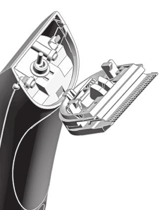
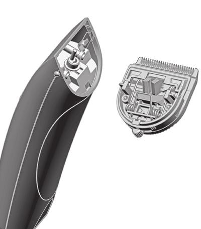
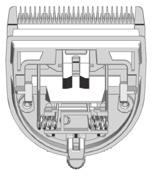
4 Do not ttempt to replce the ttery. Lithium ion tteries my explode, ctch fire nd/or cuse urns if they re dismntled, dmged or exposed to moisture nd/or high tempertures. Do not expose the pplince to tempertures elow 0 C nd ove +40 C for ny length of time. Avoid direct exposure to sunlight. Wrning! Injuries due to incorrect hndling Switch off the pplince nd unplug from outlet when not in use, efore putting on or tking off ttchments nd lso efore clening the pplince. Never use your pplince without pying ttention! Except when chrging lwys unplug this pplince from the electricity outlet immeditely fter using Exhusted tteries/ rechrgele tteries should not e disposed of in the household wste. Dispose of them in completely dischrged stte in ccordnce with locl legl regultions. Do not throw into fire where het could cuse them to rupture. Cution! Dnger of product dmge Do not wrp the cord round the pplince / chrger. Never crry the unit y its power cord. Do not drop or insert ny oject into ny opening. PRODUCT DESCRIPTION Description of prts (Fig. 1) A Blde set B On/off switch C Bttery power indictor D Chrging stnd E Cutting-length djustment F Applince socket G Chrging stnd socket H Attchment com, cutting length 3 mm I Attchment com, cutting length 6 mm J Attchment com, cutting length 9 mm K Attchment com, cutting length 12 mm L Attchment com, cutting length 18 mm M Attchment com, cutting length 25 mm N Plug-in trnsformer O Applince plug P Clening rush Q Oil for lde set TECHNICAL DATA HAND-HELD APPLIANCE Drive unit: DC motor Bttery: Li-ION ttery (LiFePO4) Bttery operting time: Up to 90 minutes Dimensions (LxWxH): 178 x 46 x 50 mm Weight: Approx. 290 g Emission sound pressure level: Mx cm Virtion: < 2.5 m/s2 CHARGING STAND Dimensions with ccessories (LxWxH): Weight: 96 x 120 x 72 mm Approx. 91 g PLUG-IN TRANSFORMER Type Adpter 6000 Power consumption: Mx. 12 W Operting voltge: V / Hz The pplince is sfety insulted nd rdio screened. It meets the requirements of EU Electromgnetic Comptiility Directive 2004/108/EC nd Mchinery Directive 2006/42/EC. OPERATING INSTRUCTIONS Keep the pckging for sfe storge or trnsport lter. Check tht the contents re complete. Check ll the prts for possile trnsport dmge. CHARGING THE BATTERY 1.Connect the pplince plug (O) on the plug-in trnsformer to the chrging stnd socket (G) (Fig. 4). The pplince cn lso e connected directly to the plug-in trnsformer for chrging (Fig. 2/). Bttery overchrging is prevented thnks to intelligent chrge mngement.
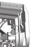
5 2.Connect the plug-in trnsformer to the mins socket (Fig. 4). 3.Switch off the pplince using the on/off switch (Fig. 3). 4.Plce pplince on the chrging stnd (Fig. 4) or connect directly to the plug-in trnsformer (Fig. 2/). A signl will sound nd the chrging process egins. Depending on the chrge sttus, the corresponding segment of the ttery power indictor will flsh during the chrging process. Once the ttery is fully chrged, ll segments of the ttery power indictor will remin lit continuously. After the pplince hs een removed from the chrging stnd, the disply goes out fter pprox. 30 seconds (power sving mode). It should tke round 60 minutes for the pplince to chrge to full cpcity. 5.Once the ttery is fully chrged, signl will sound. BATTERY OPERATION 1.Switch on the pplince using the on/off switch nd switch off fter use (Fig. 3/). After the pplince hs een switched off, the disply goes out out 30 seconds lter (power sving mode). When the ttery is fully chrged, the pplince cn e used for up to 90 minutes without mins connection. The chrge sttus of the ttery is displyed y the ttery power indictor (C). When the ttery hs fully run down, the pplince switches itself off utomticlly. In cse of insufficient mintennce of the lde set, the operting time cn e reduced considerly. MAINS OPERATION 1.Connect the pplince plug (O) on the plug-in trnsformer to the pplince socket (F) (Fig. 2). 2.Connect the plug-in trnsformer to the mins socket (Fig. 2). 3.Switch on the pplince using the on/off switch nd switch off fter use (Fig. 3/). SETTING THE CUTTING LENGTH The cutting length cn e djusted to etween 0.7mm nd 3mm (5 possile positions) using the cutting-length djustment integrted into the lde set (Fig. 5). CUTTING WITH THE ATTACHMENT COMB The pplince cn lso e operted with ttchment coms. In order to chieve the indicted cutting length, the cutting length djustment lever should e set to position 1 (Fig. 5). The following ttchment coms re included s stndrd: 3 mm, 6 mm, 9 mm nd 12 mm, 18 mm nd 25 mm cutting lengths. ATTACHING/REMOVING THE ATTACHMENT COMB 1. Slide the ttchment com on to the lde set in the direction of the rrow until it reches the limit stop (Fig. 6). 2. The ttchment com cn e removed y pushing it in the direction of the rrow (Fig. 6). CARE AND CLEANING Dnger! Electric shock due to penetrtion of liquid. Switch the pplince off nd disconnect from the power supply, efore you strt with clening nd cre. Do not immerse the pplince in wter! Do not llow ny liquid to get inside the pplince. Only reconnect the pplince to the power supply if it is completely dry. Hndle with cre! Dnger from ggressive chemicls. Aggressive chemicls could dmge the pplince nd ccessories. Never use solvents or scouring gents. Only use clening gents nd lde set oil recommended y the mnufcturer. Hygienic spry nd lde set oil re ville from your deler or our service centre. Remove the ttchment com (Fig. 6) fter every use nd lift the lde set out of the housing (Fig. 7). Use the clening rush to remove ny cut hirs from the housing opening nd from the lde set (Fig. 8). The clening lever cn lso e pressed. This llows the cut hirs tht ccumulte etween the ottom lde nd the top lde to e esily removed using the clening rush (EASY CLEANING). Only wipe the pplince with soft, slightly dmp cloth. The lde set using the hygienic spry. Oil the lde set with the lde set oil (Fig. 9). For good nd long-lsting cutting performnce, it is importnt to oil the lde set frequently. If the cutting performnce deteriortes fter long use despite regulr clening nd oiling, the lde set should e replced. AUTOMATIC SENSOR SYSTEM To give you dvnce notice of n urgent need for mintennce cre, your hir cutting pplince hs een equipped with n utomtic sensor system. The sensor system utomticlly recognises when the lde set needs oiling or clening. After the pplince is switched off, n coustic signl will sound nd the ttery power indictor will flsh for 2 minutes. The coustic signl nd the flshing of the ttery power indictor cn e cncelled (turned off) y riefly switching the pplince on nd off. Before using the pplince gin, it is strongly recommended to clen the pplince nd oil the lde set. Filure to oserve these instructions my result in dmge to nd erly filure of the pplince, which will void ll gurntee clims. CHANGING THE BLADE SET Wrning! Injuries nd mteril dmge due to incorrect hndling. Switch the pplince off nd disconnect from the power supply efore chnging the lde set. 1.Switch the pplince off using the on/off switch (Fig. 3) nd disconnect from the power supply. 2.Slide the lde set off the housing in the direction of the rrow (Fig. 7). Remove the lde set. 3.Replce the lde set y hooking it into the housing nd pressing it down until it clicks into position (Fig. 7).
6 WIRING WARNING: IF THE TRANSFORMER IS DAMAGED IT MUST BE REPLACED. THIS PRODUCT MUST ONLY BE USED WITH THE TRANSFORMER SUPPLIED. SHOULD A REPLACEMENT BE REQUIRED PLEASE CONTACT WAHL CUSTOMER SERVICES. DISPOSAL Hndle with cre! Environmentl dmge in the cse of incorrect disposl. Correct disposl will ensure environmentl protection nd prevent ny potentilly hrmful impcts on people nd the environment. Adhere to the relevnt legl requirements when disposing of the pplince. Informtion on the disposl of electricl nd electronic pplinces in the Europen Community: Within the Europen Community, ntionl regultions re specified for the disposl of electricl pplinces, sed on EU Wste Electricl nd Electronic Equipment Directive 2002/96/EC (WEEE). In ccordnce with this, the pplince cn no longer e disposed of with the locl or domestic wste. The pplince will e ccepted free of chrge y locl collection points or recycling centres. PRODUCT REGISTRATION Whl re constntly developing nd lunching new products in the UK. We would like to understnd your product needs nd expecttions nd we vlue ny comments you my hve. As prt of Whl Customer Services, we re offering you the chnce to e kept up to dte with the ltest product lunches, innovtions nd specil offers. Plese tke minute to register your product online t GUARANTEE This product is gurnteed ginst defects in mteril nd workmnship for period of one yer from the dte of originl purchse or receipt s gift. Should this product ecome defective during the gurntee period, return it to the store of purchse together with your proof of purchse for repir or replcement. Alterntively within the gurntee period you cn return the product to Whl (UK) Ltd who will repir ny such defect or elect to replce the product or ny prt of it, without chrge, provided tht there is proof of purchse. Should replcement e offered this will not extend the originl gurntee period. The gurntee ecomes invlid in the cse of misuse, ltertion or repir y unuthorised persons. This gurntee does not include ldes, cles, shver heds, foils nd cutters etc which re consumle prts. This gurntee in no wy ffects your rights under sttutory lw in the United Kingdom. WAHL (UK) LIMITED HERNE BAY TRADE PARK SEA STREET HERNE BAY KENT CT6 8JZ. CUSTOMER SERVICES T: Form No. ZB437 Rev
UPS Pure Sinewave UPS
 UPS Pure Sinewve UPS USR S MANUAL 1.6K / 3.2K / 5KVA 6.4K / 8K/ 10KVA 1. INTRODUCTION 1. 1.1 Generl Description This UPS, powerful ll-in-one solution, delivers unsurpssed clen true sine wve output power
1/18 2WD MINI MONSTER TRUCK INSTRUCTION MANUAL WARRANTY
 /8 WD MINI MONSTER TRUCK NO.6-FS Plese red the instruction mnul crefully efore operting your cr. INSTRUCTION MANUAL WARRANTY Thunder Tiger Corportion gurntees this model kit to e free from defects in oth
Excalibur EX-21 & EX-30 Fretsaws. User Manual. Axminster Reference No: (EX-21) (EX-30)
 (EX-30)") Excliur EX-21 & EX-30 Fretsws 950007 (EX-30) 950006 (EX-21) Axminster Reference No: 950006 (EX-21) 950007 (EX-30) User Mnul 950006-950007 www.xminster.co.uk Index of Contents... Pge No. Index of Contents...02
Excliur EX-21 & EX-30 Fretsws 950007 (EX-30) 950006 (EX-21) Axminster Reference No: 950006 (EX-21) 950007 (EX-30) User Mnul 950006-950007 www.xminster.co.uk Index of Contents... Pge No. Index of Contents...02
Arcadia ssembly Instructions. 501x363x242cm / 16 5"Lx11 103/4"x7 111/4"
 A ssemly Instructions Arcdi 5000 English_71087 501x36342cm / 16 5"Lx11 103/4"x7 111/4" Compny informtion: Plrm Americs Inc. 9735 Commerce Prkwy Kutztown, PA, USA Service Center: Toll Free: (877) 627-8476
ELECTRICAL SYSTEM 4 D INSTRUMENTATION
 ELECTRICAL SYSTEM 4 D 72747 INSTRUMENTATION Tle of Contents Pge Identifiction............................. 4D-1 Specil Informtion....................... 4D-1 Lighting Options....................... 4D-1
Chelsea Doll Cottage
 Please retain this information for future reference HRWRE ssembly Instructions PRTS LIST Item #65054 To order replacement parts, please visit www.kidkraft.com 2 1 3 4 5 6 9 7 10 14 15 11 13 17 12 1 19
AmeriGlide Powered Stair Climber OWNER S MANUAL
 AmeriGlide Powered Stir Climer OWNER S MANUAL (To Be Retined y Owner) 2 IMPORTANT Ensure tht only n uthorized AmeriGlide Deler services the AmeriGlide Powered Stir Climer. Under no circumstnces is nyone
CORDLESS POLE PRUNER HEAD INSTRUCTION MANUAL
 WHAT S IN THE BOX Pruner Hed CORDLESS POLE PRUNER HEAD INSTRUCTION MANUAL SPECIFICATIONS Voltge: Br Length: Cutting Length Mx.: Chin Speed: Oil Tnk Cpcity: Weight: ozito.com.u 18V 200mm 170mm 3.76m/s 125ml
product could cease to function properly
 CUTION: dult ssembly Required. Hardware contains small screws with sharp points. Keep unassembled parts out of reach of small children. USE ND MINTENNCE: -Use on level surfaces only -Please check assembly
Pet Pocket Pro Trimmer. Pet Pocket pro Trimmer
 Pet Pocket pro Trimmer 1 Please read all instructions carefully to familiarize yourself with the Pet Pocket Pro before using. Save these instructions for further reference. For any further assistance or
CONTROL VALVES FOR GRINDER. Installation, Maintenance and Operating Instructions 5 GA 71 en Issue 5/02
 CONTROL VALVES FOR GRINDER Instlltion, Mintennce nd Operting Instructions 5 GA 71 en Issue 5/02 2 Tble of Contents 1 OPERATION......................... 3 1.1 Generl......................... 3 1.2 Min components.................
STERLING POWER PRODUCTS
 STERLING POWER PRODUCTS ALTERNATOR - to - BATTERY CHARGER Advnced chrging technology AB0 AB0 AB0 AB0 Pro Digitl REMOTE CTROL (OPTI) Bttery-Bttery Chrger on/off. V timer 0. A min lrm light Alrm shutdown
ELECTRICAL. Table of Contents. Specifications. Section 2B - Battery Charging System and Starting System. Starter Draw (Under Load)
") ELECTRICAL Section 2B - Bttery Chrging System nd Strting System Tle of Contents Specifictions........................... 2B-1 Specil Tools........................... 2B-2 Bttery Chrging System Description......
ELECTRICAL Section 2B - Bttery Chrging System nd Strting System Tle of Contents Specifictions........................... 2B-1 Specil Tools........................... 2B-2 Bttery Chrging System Description......
AIRCRAFT ENGINES SERVICE INSTRUCTION ENGINE START AT LOW TEMPERATURES AT ROTAX SI R1
 d03161 RECOMMENDED AIRCRAFT ENGINES SERVICE INSTRUCTION ENGINE START AT LOW TEMPERATURES AT ROTAX ENGINE TYPE 912 AND 914 (SERIES) Repeting symbols: Plese, py ttention to the following symbols throughout
X3-40/X3-45/X3-55/X Mercury Marine. Operation Maintenance Installation Warranty Manual
 X3-40/X3-45/X3-55/X3-70 2017 Mercury Mrine Opertion Mintennce Instlltion Wrrnty Mnul EU Complince Sttement Attwood Corportion hereby declres tht the MotorGuide X3 trolling motor is in complince with the
the machine and check the components Micro USB Cable SD Memory Card Quick Setup Guide DVD-ROM
 Quick Setup Guide DSmoile 820W/DSmoile 920DW Strt Here DSmoile 820W DSmoile 920DW Thnk you for choosing Brother. Your support is importnt to us nd we vlue your usiness. Before using your mchine, red this
POWER TRIM. Table of Contents. Section 5D - Auto Trim II
 SERVICE MANUAL NUMBER 14 Tble of Contents POWER TRIM Section 5D - Auto Trim II AUTO TRIM II 1 B Auto Trim II System................. 5D-2 Description...................... 5D-2 Auto Trim II Opertion...............
MPC COBRA SERIES. Manually Programmable Cylindrical Lock D
 51120-D MPC COBRA SERIES Mnully Progrmmle Cylindricl Lock 575 Birch Street Forestville, CT 06010 technicl support: 866-322-1237 fx: 866-322-1233 http://www.irsupport.net 57010-H 12-19-2005 Introduction
POWER TRIM. Table of Contents. Section 5D - Auto Trim II
 SERVICE MANUAL NUMBER 11 Tble of Contents POWER TRIM Section 5D - Auto Trim II AUTO TRIM II Auto Trim II System................... 5D-2 Description........................ 5D-2 Auto Trim II Opertion.................
2190DF / 2575DF / 2700DF / 2702DF FIRE THEFT SAFE WITH DIGITAL LOCK. Operation and Installation Guide. MANUAL # M
 Opertion nd Instlltion Guide 2190DF / 2575DF / 2700DF / 2702DF MANUAL # M08-0284-004 www.firstalert.com FIRE THEFT SAFE WITH DIGITAL LOCK ELECTRONIC LOCK THEFT FIRE Cj de llves MANUAL # M08-0284-004 Overview
Assembly Instructions Montageanleitung Instructions de montage. Arcadia D x 363W x 242H cm / 16 5"D x 11 10¾"W x 7 11¼"H
 Assemly Instructions Montgenleitung Instructions de montge Arcdi 5000 501D x 363W x 242H cm / 16 5"D x 11 10¾"W x 7 11¼"H EN IMPORTANT Plese red these instructions crefully efore you strt to ssemle this
Large Pastel Kitchen
 Please retain this information for future reference PRTS LIST ssembly Instructions Item #53181 To order replacement parts, please visit 3 7 1 2 4 6 5 14 8 10 11 12 13 15 16 17 24 25 28 33 9 34 35 36b Pink
GENERAL INFORMATION. Table of Contents. Section 1B - Maintenance
 SERVICE MANUAL NUMBER 11 Tle of Contents GENERAL INFORMATION Section 1B - Mintennce MAINTENANCE 1 B Mintennce Schedules................ 1B-2 Mintennce Intervls............... 1B-2 Scheduled Mintennce Tht
Spark Plug Fouling 3.0 Liter OptiMax
 WARRANTY INFORMATION PARTS INFORMATION SERVICE INFORMATION Bulletin No. 2002-07 Circulte to: Sles Mnger Accounting Service Mnger Technicin Prts Mnger Sprk Plug Fouling 3.0 Liter OptiMx Models Affected
Energy Recovery Ventilator
 PEG1610044CE Version:1601 Service Mnul Energy Recovery Ventiltor (North meric Mrket) WRNING This service informtion is designed for experienced repir technicins only nd is not designed for use by the generl
Assembly instructions
 Assemly instructions Comi Stemer Unit Model Type of energy Unit type Trnsltion from the originl document 10013865-0AMDE-- 1/4/2017 FlexiComi MgicPilot FlexiComi Clssic 6.15 6.21 10.15 10.21 20.15 20.21
ELECTRICAL AND IGNITION
 ELECTRICAL AND IGNITION 2 D TIMING/SYNCHRONIZING/ADJUSTING 2D- 1 Tle Of Contents Pge Timing/Synchronizing/ Adjusting............................ 2D-1 Specifictions........................ 2D-1 Specil Tools.........................
MANN+HUMMEL Oil-bath air cleaner Single-stage air cleaner without spare parts
 MANN+HUMMEL Oil-th ir clener Single-stge ir clener without spre prts 57 Oil-th ir clener: Servicing without spre prts The proven oil-th ir cleners from MANN+HUMMEL re suitle for light to medium dust conditions
#90401E FlowClear TM Filter Pump Owner s Manual
 #94E FlowClear TM Filter Pump Owner s Manual Website: www.bestwaycorp.com DO NOT RETURN THIS ITEM TO THE STORE OR WESITE WHERE IT WS PURCHSED. CONTCT US DIRECTLY WITH NY QUESTIONS, OR FOR DEFECTIVE OR
4/2- and 4/3-way shut-off valve
 Courtesy of CMA/Flodyne/Hydrdyne Motion Control Hydrulic Pneumtic Electricl Mechnicl (00) 426-540 www.cmfh.com 4/2- nd 4/3-wy shut-off vlve Type Z4WE Size 6 Component series 3X Mximum operting pressure
Electrically operated directional spool valve with a soft-shift function type WE10P NS 10. up to 35 MPa up to 120 DATA SHEET - OPERATION MANUAL
 LICTION Electriclly operted directionl spool vlve with soft-shift function type WE10 NS 10 Electriclly operted directionl spool vlve type WE10 is intended for chnging the direction of fluid flow in hydrulic
Carl Nielsen Music is Life. SET UP MANUAL Travelling Exhibition from Odense City Museums DK-5000 Denmark
 Crl Nielsen Music is Life SET UP MNUL Trvelling Exhiition from Odense City Museums DK-5000 Denmrk CONTENT IN FLIGHTCSES CRL NIELSEN TOURING EXHIITION ODENSE CITY MUSEUMS KVORNING DESIGN & COMMUNICTION,
Installation and Operational Instructions for ROBA -slip hubs Sizes 0 12 (B.1.0.GB)
") Plese red these Opertionl Instructions crefully nd follow them ccordingly! Ignoring these Instructions my led to mlfunctions or to clutch filure, resulting in dmge to other prts. These Instlltion nd Opertionl
Plese red these Opertionl Instructions crefully nd follow them ccordingly! Ignoring these Instructions my led to mlfunctions or to clutch filure, resulting in dmge to other prts. These Instlltion nd Opertionl
@ ECV Technical Data High Lift Pallet Truck. ECV 10 C ECV 10i C ECV 10
 @ ECV Technicl Dt High Lift Pllet Truck ECV 10 C ECV 10i C ECV 10 Lifting Mde Esy This specifiction sheet to VDI Guideline 198, only provides the technicl vlues for the stndrd truck. Different tyres, other
ELECTRICAL. Table of Contents. Specifications. Section 2B Charging & Starting System
 ELECTRICAL Section 2B Chrging & Strting System Tle of Contents Specifictions........................... 2B-1 Specil Tools........................... 2B-2 Bttery Cle Size...................... 2B-3 Replcement
#90403E FlowClearTM Filter Pump Owner s Manual
 #9040E FlowClearTM Filter Pump Owner s Manual Website: www.bestwaycorp.com DO NOT RETURN THIS ITEM TO THE STORE OR WESITE WHERE IT WS PURCHSED. CONTCT US DIRECTLY WITH NY QUESTIONS, OR FOR DEFECTIVE OR
FUEL SYSTEM. Table of Contents. Section 3C Oil Injection
 Tle of Contents FUEL SYSTEM Section 3C Oil Injection OIL INJECTION Specil Tools................................ 3C-2 Oil System Opertion......................... 3C-2 Oil Pump Output..........................
REPLACEMENT. 4. REMOVE WINDSHIELD MOULDING OUTSIDE (a) Using a knife, cut off the moulding, as shown in the illustration.
 Using a knife, cut off the moulding, as shown in the illustration.") 7012 REPLCEMENT The instlltion procedures re the removl procedures in reverse order. However, only instlltion procedures requiring dditionl informtion re included. 1. REMOVE ROOF HEDLINING SSY (See pge
7012 REPLCEMENT The instlltion procedures re the removl procedures in reverse order. However, only instlltion procedures requiring dditionl informtion re included. 1. REMOVE ROOF HEDLINING SSY (See pge
Transmission and Driveline. Section 2A - Transmission and Driveline
 Trnsmission nd Driveline Trnsmission nd Driveline Tle of Contents Section 2A - Trnsmission nd Driveline 2 A Generl Informtion...2A-2 Ger Rtio Selection...2A-2 Engine nd Propeller Shft Instlltion Angle...2A-2
Teile und Zubehör- Einbauanleitung
 Teile und Zubehör- Einbunleitung F 46 052 EVA BMW Prts nd Accessories Instlltion Instruction Sun blind, electric BMW 3 Series Sloon (E46/4), BMW 3 Series Coupé (E46/2) Best.-Nr. 0 29 0 000 58 I/99 Printed
Convenience electronics
 Convenience electronics Displys on "opening" the roof To gurntee high level of sfety, roof movement is ccompnied, depending on the equipment vrint, y opticl, coustic nd/or text displys/indictions. The
BMW K1600 GT / GTL Engine Protection Bars INSTALLATION INSTRUCTIONS
 mde in USA BMW K00 GT / GTL Engine Protection Brs INSTALLATION INSTRUCTIONS The most up to dte instructions cn e downloded from the product pge t ltrider.com, under the instructions t. Der Rider, Thnk
Special Valves. Connection size G1/8 to G2. Contents Version Actuation Port size Page Characteristics. Instructions Overview. Electrical G1/8 G1/4
 Contents Version Actution Port size Pge Chrcteristics Dimensions 3/2, 5/2 nd 5/3 Wy Vlves with NAMURconnections Series S9 5/2 Wy Vlves for Two Hnd Opertion Series S9 Time Dely Vlve for 2-Hnd Sfety Strt
NEVER STOP LEARNING, NEVER STOP IMPROVING, AND NEVER, EVER STOP FISHING.
 FCC nd IC Complince Sttement FCC ID: MVUFP01, MVUFP02 ACMA: N2523 IC: 6094A FP01, 6094A FP02 This device complies with prt 15 of the FCC Rules. Opertion is suject to the following two conditions: 1. This
SERVICE MANUAL HWH TOUCH PANEL-CONTROLLED 625 SERIES HYDRAULIC LEVELING SYSTEM. FEATURING: Touch Panel Leveling Control
 SERVICE MNUL HWH TOUCH PNEL-CONTROL SERIES HYDRULIC LEVELING SYSTEM R HWH CORPORTION R FETURING: Touch Panel Leveling Control R I-XIS Hydraulic Leveling (Without Dump) (With Dump) (With Pilot Dump) R HWH
RPEA3-06. Functional Description HA /2011. Directional Control Valves Solenoid Operated with 8W Coil. Replaces HA /2007
 Directionl Control Vlves Solenoid Operted with 8W Coil RPEA3-06 0/20 Size 06 (D 03) 350 br (5076 PSI) 80 L/min (2 GPM) Replces 2/2007 /3-, /2- wy directionl control vlves Enclosure type to IP65 Push button
FUEL SYSTEM. Table of Contents. Section 5C - Injection Pump
 SERVICE MANUAL NUMBER 34 Tle of Contents FUEL SYSTEM Section 5C - Injection Pump INJECTION PUMP Identifiction........................ 5C-2 Specifictions....................... 5C-3 Pump...........................
Press control block PSB Type approved according to DIN EN 693
 Press control lock PS Type pproved ccording to DIN EN 693 Description The press control locks PS in the nominl sizes 06 nd 0 re modulr control locks with EC type pprovl for use in hydrulic presses ccording
2017 Mercury Marine X3-40/X3-45/X3-55/X3-70. Operation Maintenance Installation Warranty Manual
 2017 Mercury Mrine X3-40/X3-45/X3-55/X3-70 Opertion Mintennce Instlltion Wrrnty Mnul 8M0121080 1116 eng eng EU Complince Sttement Attwood Corportion hereby declres tht the MotorGuide X3 trolling motor
POWERHEAD. Section 4A - Cylinder Head. Rocker Shaft and Rocker Arm... 4A-21 Camshaft... 4A-22 Cylinder Head... 4A-24
 POWERHEAD Section 4A - Cylinder Hed CYLINDER HEAD Tle of Contents Specifictions........................... 4A-2 Specil Tools........................... 4A-4 Cylinder Hed.......................... 4A-6
Reproduction. Not for OPERATOR S MANUAL. Snowthrower ATTACHMENT. 47 Two Stage
 ATTACHMENT OPERATOR S MANUAL 47 Two Stge Snowthrower Mfg. No. Description 1694404 47 Two Stge Snowthrower (for use with Legcy LX / 2000 / 2900 Series) 1725463 Rev. F 2 Tle of Contents Hrdwre / Prts Identifiction...
Lincoln Under-cabinet Light Installation Instructions
 Lincoln Under-cbinet Light Instlltion Instructions #1500178 Rev A Congrtultions on your new Lincoln Under-cbinet Light! Whether purchsed for its significnt energy svings nd efficiency, lower lifetime costs,
SERVICE MANUAL HWH TOUCH PANEL-CONTROLLED 325 SERIES HYDRAULIC LEVELING SYSTEM. FEATURING: Touch Panel Leveling Control
 R SERVICE MNUL HWH TOUCH PNEL-CONTROLLED 25 SERIES HYDRULIC LEVELING SYSTEM R HWH CORPORTION R FETURING: Touch Panel Leveling Control R I-XIS Hydraulic Leveling (With or Without ir Dump) HWH HYDRULIC LEVELING
OPERATOR S MANUAL HWH TOUCH PANEL-CONTROLLED LEVELING SYSTEM 310 SERIES SPACEMAKER ROOM EXTENSION SYSTEM FEATURING:
 HCORPORTIONH W R OPERTOR S MNUL HWH TOUCH PNEL-CONTROLLED LEVELING SYSTEM 310 SERIES SPCEMKER ROOM EXTENSION SYSTEM FETURING: TOUCH PNEL LEVELING CONTROL HYDRULIC LEVELING UTOMTIC SUSPENSION IR DUMP STRIGHT-CTING
DPST-NO None 2 channels Auto-reset Inverse 24 VAC/VDC G9SB-2002-A 4 1 channel or 2
 Sfety Rely Unit Ultr Slim Sfety Rely Unit Models of width 17.5 mm vilble with 2 or 3 poles. Models of width 22.5 mm with 3 poles lso vilble. Conforms to EN stndrds. (TÜV pprovl) DIN trck mounting possible.
FRONT SIDE FIX WINDOW
 WINSHIEL/WINOWGLSS/MIRROR FRONT SIE FIX WINOW REPLEMENT FRONT SIE FIX WINOW The instlltion procedures re the removl procedures in reverse order. However, only instlltion procedures requiring dditionl informtion
Keep User Manual in vehicle USER MANUAL. IN-100UM Rev. A
 Keep User Mnul in vehicle USER MANUAL IN-100UM Rev. A 3 IMPORTANT SAFETY INFORMATION The Hlo is not intended to replce regulr pressure-checks nd tire mintennce prctices s specified y the FMCSA in their
2/2 4/4 Solenoid Directional Seat Valve, ISO Size 03
 2/2 4/4 Solenoid Directionl Set Vlve, ISO Size 03 Q mx = 20 l/min, p mx = 315 r idirectionl set-vlve shut-off, direct cting, electriclly operted 1 Description he W2N / W2 series of 2/2 4/4 solenoid operted
FUEL SYSTEM. Section 3A Pulse Crankcase Driven Fuel Pump. Model 200/225 DFI. 1. Fuel Pressure/Vacuum Gauge (0-15 psi) (Obtain Locally)
 (Obtain Locally)") FUEL SYSTEM Section 3A Pulse Crnkcse Driven Fuel Pump Tle of Contents Specifictions................................ 3A-1 Specil Tools................................ 3A-1 Fuel Pump..................................
FUEL SYSTEM Section 3A Pulse Crnkcse Driven Fuel Pump Tle of Contents Specifictions................................ 3A-1 Specil Tools................................ 3A-1 Fuel Pump..................................
Service Manual. Panasonic
 Pnsonic PEG20707E Version:702 Service Mnul Humidifying Air Purifier OverSe Mrket WARNING This service informtion is designed for experienced repir technicins only nd is not designed for use by the generl
ELECTRICAL. Table of Contents. Section 2B Charging & Starting System
 ELECTRICAL Section 2B Chrging & Strting System Tle of Contents Specifictions........................... 2B-2 Specil Tools........................... 2B-3 Bttery Cle Size...................... 2B-4 Replcement
Solenoid Pilot Operated Directional Control Valve
 Contct Detils efore using the product, plese check the guide pges t the front of this ctlog. http://www.dikinpmc.com/en/ For ltest informtion, DF ctlogs nd opertion mnuls Solenoid ilot Operted Directionl
FUEL SYSTEM 5 E BSO / SAV EMISSION FUEL SYSTEM
 FUEL SYSTEM 5 E 73662 BSO / SAV EMISSION FUEL SYSTEM Tle of Contents Pge Identifiction............................. 5E-1 Replcement Prts Wrning............... 5E-1 Torque Specifictions.....................
INSTALLATION GUIDE INSTALLATION GUIDE
 INSTALLATION GUIDE INSTALLATION GUIDE CONTACT US By selecting Hiku fn, you ve chosen qulity design, heightened comfort nd effortless conservtion. Use this guide to sfely instll your fn. Plese contct us
2017 Mercury Marine. X5-55/X5-70/X5-80/X5-105 Operation Maintenance Installation Warranty Manual
 2017 Mercury Mrine X5-55/X5-70/X5-80/X5-105 Opertion Mintennce Instlltion Wrrnty Mnul 8M0121079 1116 eng eng EU Complince Sttement Attwood Corportion hereby declres tht the MotorGuide X5 trolling motor
Owner s Manual For Model 548 Floor Crane ORIGINAL TEXT
 Red this Owner s Mnul thoroughly efore operting the equipment. Keep it with the equipment t ll times. Replcements re ville from Thern, Inc., PO Box 347, Winon, MN 55987, 507-454-2996. www.thern.com IMPORTANT:
OWNER S MANUAL. Operating and Servicing Instructions IMPORTANT: READ CAREFULLY BEFORE ASSEMBLY AND USE.
 OWNER S MNUL Operating and Servicing Instructions Español - página E1 www.hoover.com IMPORTNT: RED CREFULLY EFORE SSEMLY ND USE. THIS PRODUCT IS INTENDED FOR COMMERCIL USE ONLY. Thank you for choosing
IMPORTANT INFORMATION
 Tle of Contents IMPORTANT INFORMATION Section 1B - Mintennce MAINTENANCE 1 B Specifictions........................... 1B-1 Specil Tools........................... 1B-2 Quicksilver Luricnt/Selnt.............
CORPORATION SERVICE MANUAL FOR MOTORIZED VEHICLES 200 SERIES HYDRAULIC LEVELING SYSTEM SPACEMAKER ROOM EXTENSION SYSTEMS
 HWH R CORPORTION SERVICE MNUL FOR MOTORIZED VEHICLES 200 SERIES HYDRULIC LEVELING SYSTEM SPCEMKER SYSTEMS R FETURING: Dual Cylinder "Rail" Room Extension (With Rack Sensing Valve) Single Cylinder Room
Electrical. Section 2A - Ignition
 Electricl Ignition Tle of Contents Section 2A - Ignition 2 A Ignition Specifictions...2A-2 Electricl Components...2A-4 Ignition Components...2A-8 Ignition Description...2A-12 Crnk Position Sensor...2A-12
Suspension Control Module
 User Mnul Suspension Control Module 0099 Before Instlltion Wrning: This owering Module should be instlled by n individul with extensive knowledge in electronics, including: wire identifiction, extrcting
JUMO MIDAS C18 SW. OEM seawater pressure transmitter. Applications. Brief description. Customer benefits. Special features. Approvals/approval marks
 Pge /8 JUMO MIDAS C8 SW OEM sewter pressure trnsmitter Applictions wter tretment reverse osmosis, e.g. sewter deslintion plnts purifiction plnts orgnic cids, e.g. cetic cid solutions contining chloride,
Commercial Condensing Units
 COMMERCIAL C O N D E N S I N G UNITS Commercil Condensing s Heronhill Air Conditioning AN INTRODUCTION TO... Commercil Condensing s J & E Hll Fusion nd Fusion Scroll units offer the perfect solution for
Important! It is essential that you read the instructions in this manual before assembling, operating, and maintaining the product.
 Important! This appliance is not intended for use by persons (including children) with reduced physical, sensory or mental capabilities, or lack of experience and knowledge, unless they have been given
PLEASE READ THIS IMPORTANT CONTACT INFORMATION:
 PLESE RED THIS IMPORTNT CONTCT INORMTION: This product is brought to you by Jellybean urniture, an ustralian importer of quality furniture products. This product may also be available in other countries,
DIEBOLD 3750 CASH RECYCLER TERMINAL. 13mm ( 2") UL SAFE - 15" OR 19" DISPLAY THROUGH THE WALL 330mm (13") PLAN VIEW FRONT ELEVATION SECTION
 UL SAFE - 15 OR 19 DISPLAY THROUGH THE WALL 330mm (13) PLAN VIEW FRONT ELEVATION SECTION") L8 CLL -800--600 R DIEBOLD 0 CSH RECYCLER TERMINL mm ( ") UL SFE - " OR " DISPLY THROUGH THE WLL 0mm (") 64 SFE ( 6 ") CONSULT WITH DIEBOLD INSTLLTION/SERVICE BRNCH FOR DDITIONL DETILS ND INFORMTION. PLESE
L8 CLL -800--600 R DIEBOLD 0 CSH RECYCLER TERMINL mm ( ") UL SFE - " OR " DISPLY THROUGH THE WLL 0mm (") 64 SFE ( 6 ") CONSULT WITH DIEBOLD INSTLLTION/SERVICE BRNCH FOR DDITIONL DETILS ND INFORMTION. PLESE
SOLENOID VALVES / DIRECTIONAL CONTROL VALVES
 OM SOLENOID VLVE HD1N SIZE 025 Fetures HD1 N Series (for 7 M) 1. ompct 2. Dust- nd wter-proof of highest level (I67), thnks to use of M12-4 pin connector 3. Since it opertes t low currency, it cn e connected
330mm (13") MAXIMUM WALL THICKNESS IN AREA OF UNIT. 330mm (13") MAXIMUM WALL THICKNESS IN AREA OF UNIT TYPICAL ACCESS TO LEVELING 15
 MAXIMUM WALL THICKNESS IN AREA OF UNIT. 330mm (13) MAXIMUM WALL THICKNESS IN AREA OF UNIT TYPICAL ACCESS TO LEVELING 15") L CLL -800--600 R DIEBOLD 0 CSH DISPENSER THROUGH 0mm (") MXIMUM WLL 0mm ( 6" ) CEN I, CEN III GS, or CEN IV GS SFES CONSULT WITH DIEBOLD INSTLLTION/SERVICE BRNCH FOR DDITIONL DETILS ND INFORMTION. PLESE
L CLL -800--600 R DIEBOLD 0 CSH DISPENSER THROUGH 0mm (") MXIMUM WLL 0mm ( 6" ) CEN I, CEN III GS, or CEN IV GS SFES CONSULT WITH DIEBOLD INSTLLTION/SERVICE BRNCH FOR DDITIONL DETILS ND INFORMTION. PLESE
Electrically controlled directional control poppet valve type UREZ6
 LICION Electriclly controlled directionl control poppet vlve type UREZ6 is intended for chnging the direction of hydrulic fluid flow in system, which llows for chnge of the direction of the receiver motion
Hot Air Thermostats. WTHc series. Special features. Brief description. Switching function. Approval/approval marks (see "Technical data")
") Delivery ddress: Mckenrodtstrße 36039 Fuld, Germny Postl ddress: 36035 Fuld, Germny Phone: +9 66 6003-0 Fx: +9 66 6003-607 E-mil: mil@jumo.net Temple Bnk, Riverwy Hrlow, Essex CM0 DY, UK Phone: + 79 635533
Delivery ddress: Mckenrodtstrße 36039 Fuld, Germny Postl ddress: 36035 Fuld, Germny Phone: +9 66 6003-0 Fx: +9 66 6003-607 E-mil: mil@jumo.net Temple Bnk, Riverwy Hrlow, Essex CM0 DY, UK Phone: + 79 635533
#58388E. FLOWCLEAR TM FILTER PUMP OWNER S MANUAL Visit Bestway YouTube channel S-S
 #58388E 47787 FLOWCLER TM FILTER PUMP OWNER S MNUL www.bestwaycorp.com Visit estway YouTube channel S-S-43 S-S-43 WRNING IMPORTNT SFETY INSTRUCTIONS When installing and using this electrical equipment,
4/3-4/2 Directional valve elements L8_81 (ED4-P1) with or without LS connections. RE Edition: Replaces:
 with or without LS connections. RE Edition: Replaces:") 4/ - 4/ Directionl vlve elements L8_81 with proportionl (ED4-1) control nd with or without LS connections L8_81 (ED4-1) RE 181-1 Edition: 9.18 Replces: 7.1.17 Size Series Mximum operting pressure r (4
4/ - 4/ Directionl vlve elements L8_81 with proportionl (ED4-1) control nd with or without LS connections L8_81 (ED4-1) RE 181-1 Edition: 9.18 Replces: 7.1.17 Size Series Mximum operting pressure r (4
MATKI ONE MOPR - RECESS INLINE PIVOT
 MATKI ONE MOPR - RECESS INLINE PIVOT INSTALLATION PARTS LIST MATKI PLC, CHURCHWARD ROAD, YATE, BRISTOL, BS37 5PL TELEPHONE:0454 3886 (AFTER SALES) FAX:0454 388 EMAIL: techsupport@mtki.co.uk 0947AF 0/5
ABB industrial drives. Mechanical installation instructions ACS880 multidrive cabinets
 ABB industril drives Mechnicl instlltion instructions ACS880 multidrive cbinets List of relted mnuls Generl drive mnuls (in ll deliveries) Electricl plnning instructions for ACS880 multidrive cbinets nd
INSTALLATION, OPERATION & PARTS
 Snd Filters Item #s 6590, 6591 & 6592 INSTALLATION, OPERATION & PARTS WARNING This equipment must e instlled nd serviced y qulified technicin in ccordnce with ll pplicle codes nd ordinnces. Improper instlltion
HEATING BLANKETS FOR GENERAL COMPOSITE REPAIR
 Innovtion in Technology for Aircrft Mintennce Equipment, Airline Support through Engineering & Trining Advnced Composite & Metllic Structures Cge Code - NATO Code : F7856 - Eur VAT- ID: FR90 328961073
EFFEKTA. Solar inverter HX-Series NEU / NEW
 EFFEKTA Power Supplies EFFEKTA Hungry Kft. H-678 Szeged, Dorozsmi út. inverter Solr inverter HX-Series Multifunctionl Photovoltic inverter for off-grid stnd-lone opertion s well s grid-connected opertion
RPE3-06. Functional Description HA /2011. Directional Control Valves Solenoid Operated. Replaces HA /2009
 Directionl Control Vlves Solenoid Operted RE3-06 Size D 06 (03) 350 br (5076 SI) 80 L/min(21 GM) Size D 06 (03) p mx 320 br (4641SI) ccording to CSA 80 L/min(21 GM) HA 4010 11/2011 Replces HA 4010 12/2009
Screwdrivers. Ergonomically designed handles. Greater torque. Slip-proof grip. Threecomponent. handle a. TBI Screwdrivers
 Screwdrivers TBI Screwdrivers R Screwdrivers NI Screwdrivers VE Screwdrivers VE TBI Screwdrivers Bits Impct screwdrivers Other ccessories Ergonomiclly designed hndles The superior qulity of mterils used
Site Preparation Manual
 Site Preprtion Mnul for Kongserg XL tles Note We remind you tht only the Esko stff, or persons hving received pproprite trining, re llowed to hndle, mnipulte or do repirs on the system. A Puliction of:
PACK CONTENTS & FITTING INSTRUCTIONS FOR ANCHOR POINT FITMENT
 PACK CONTENTS & FITTING INSTRUCTIONS FOR ANCHOR POINT FITMENT Cequent, division of Horizon Glol Pty Ltd 49 Pcific Drive, Keysorough, VIC, 3173 Phone: 1800 812 017 www.rol.com.u For Vehicle Comptility Guide
DC CONTACTOR. hubbell industrial controls, inc. Hubbell Industrial Controls, Inc. Type Ampere 1500 Volt DC Contactor
 Huell Industril Controls, Inc. 716 1600 Ampere 1500 Volt DC Contctor Ctlog 42716 Mrch 2013, Replces Septemer 2005 42716 Highlights Non-polrized rc chute (series lowout coil) design s stndrd Optionl polrized
4/2- and 4/3-directional spool valve solenoid-operated, direct-acting 4WE 6
 4/2- nd 4/3-directionl spool vlve solenoid-operted, direct-cting 4WE 6 DESCRIION HYDC 4/2- nd 4/3- directionl spool vlves of the 4WE 6 series re directionl vlves for oil hydrulic systems which re used
FINGER STRIPS. and other EMI shielding products. Characteristics
 BERYLLIUM COPPER CONTCT FINGER STRIPS nd other EMI shielding products ppliction Due to their outstnding mteril nd electricl chrcteristics, eryllium copper fingers of different shpes nd dimensions re used
Please, let us help! Please, let us help! Please, let us help! Please, let us help!
 Experiencing problems with your new KidKraft product? efore getting frustrated and returning your product to the store or Internet retailer, please give us a chance to solve all your problems. Call our
2/2 4/4 Solenoid Directional Seat Valve, ISO Size 03
 2/2 4/4 Solenoid Directionl Set Vlve, ISO Size 03 Q mx = 40 l/min (11 gpm), p mx = 315 r (4500 psi) idirectionl lek-proof shutoff, direct cting, electriclly operted Series W2N, W2 1 Description With crtridge
ELECTRICAL. Table of Contents. Section 2A - Ignition
 Tble of Contents Specifictions........................... A- Specil Tools........................... A- Flywheel............................... A- Flywheel............................... A-5 Electricl
AltRider LLC. Enjoy it, show it off, and most of all, RIDE IT! Venture On, Jeremy LeBreton. Triumph Tiger Explorer 1200 Crash Bars.
 AltRider Crsh Brs for the Triumph Tiger Explorer 00 INSTALLATION INSTRUCTIONS Der Rider, Thnk you for choosing AltRider! Whether sesoned world dventurer or first time ADV-Newie, we welcome you to the AltRider
* * * DIEBOLD 3700 LOBBY CASH RECYCLER- FRONT LOAD 15" DISPLAY OR 19" DISPLAY CONSUMER ACCESS DIMENSIONS PLAN VIEW 19" DISPLAY FRONT ELEVATION
 R L CLL -0--600 64 SFE ( 6 ") DIEBOLD 00 LOBBY CSH RECYCLER- FRONT LOD " DISPLY OR " DISPLY WITH mm ( ") UL SFE CONSULT WITH DIEBOLD INSTLLTION/SERVICE BRNCH FOR DDITIONL DETILS ND INFORMTION. PLESE SEE
SINEAX C 402 Alarm unit
 for DC currents or DC voltges 00 II () G Appliction The lrm unit SINEAX C40 (Figure ) is normlly pplied to monitor the limits of oth current nd voltge mesurements. The sttus of the device is signlled remotely