240 g. 290 g. Electric Actuators. Compact and lightweight. New. Series LEPY/LEPS. Offering 2 types of controller
|
|
|
- Charles Hill
- 5 years ago
- Views:
Transcription


1 Electric Actuators Miniature Rod Type Compact and lightweight Rod Type Series LEPY Miniature Slide Table Type New RoHS Maximum pushing force: N Positioning repeatability: ±. mm Possible to set position, speed and force. (6 points) Size: 6, Weight 2 g LEPY6-2 mm 2. mm 2.6 mm Slide Table Type Series LEPS Size: 6, Weight 29 g LEPS6-2 Linear guide integrated mm 2 mm 8.6 mm Offering 2 types of controller Step data input type Series LECP6 6 points positioning Input using controller setting kit or teaching box Series LEPY/LEPS Programless type Series LECP points positioning Control panel setting CAT.EUS-92A-UK

 Miniature Slide")

 High pushing force")


![Pushing force [N] Basic Compact](/docs-images/84/89195649/images/2-11.jpg "to 2 7 to 2 to 2 to 2.")
 Max.")
![work load [kg] (Vertical) Basic](/docs-images/84/89195649/images/2-13.jpg "Compact Basic Compact Basic...7.")
")
2 Electric Actuators Rod Type Series LEPY Miniature Rod Type Compact and lightweight Weight 2 g (LEPY6-2) Miniature Slide Table Type Slide Table Type Motor type can be selected to suit the application. (Size only) High pushing force type/basic type Compact and lightweight motor type Weight Series LEPS 29 g (LEPS6-2) Linear guide Body mounting through-hole Manual override screw For rod/table operation. Adjustment operation possible when power Body mounting through-hole Can be mounted close together. Application Examples Pick and place Delivery Alignment Press fitting Variations Type Rod type Series LEPY Size 6 Screw lead 8 Pushing force [N] Basic Compact to 2 7 to 2 to 2 to 2. to 2 2 to 2 Max. work load [kg] (Horizontal) Max. work load [kg] (Vertical) Basic Compact Basic Compact Basic Max. speed [mm/s] (Horizontal) Compact 2 Stroke [mm] 2 7 Slide table type Series LEPS Features 6 8 to 2 7 to 2 to 2. to 2 2 to 2 to


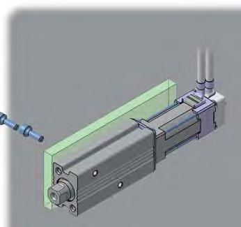
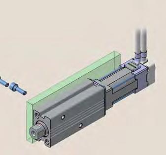
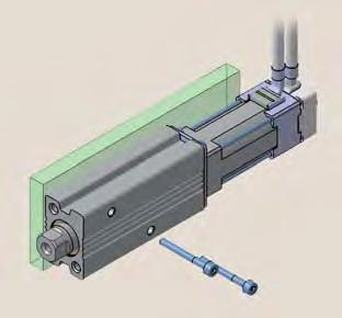
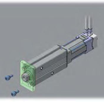
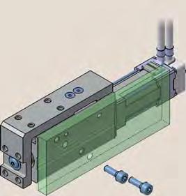

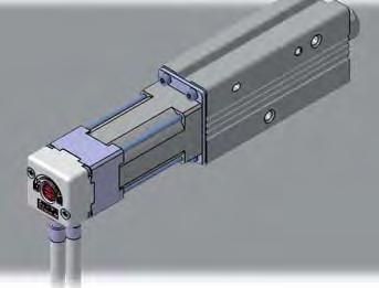
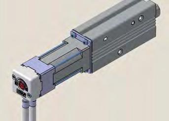
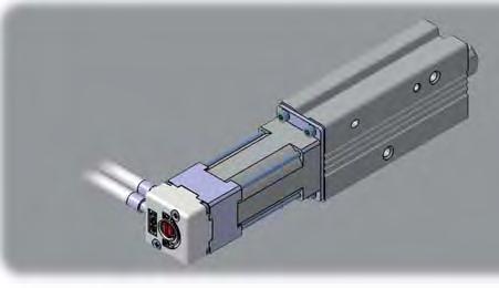
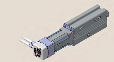
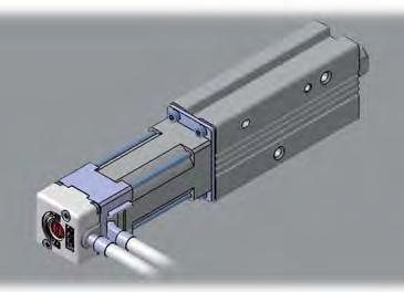
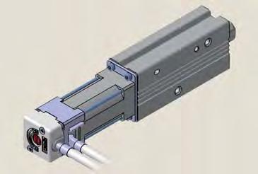
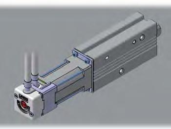
3 Series LEPY/LEPS Mounting Variations Mounting from various directions Side mounting (Body mounting through-hole) Side mounting (Body tapped) For slide table type, mounting from both sides is possible. For slide table type, body tapped from both sides. Bottom mounting (Body tapped) Axial mounting Rod type only (Body tapped) Motor Cable Entry Direction Can be selected from directions. Top entry (Basic model) Entry on the right side (When selecting R ) Bottom entry (When selecting U ) Entry on the left side (When selecting L ) Features 2
 LECP6 <When using a PC> Controller setting software Step data setting, test operation, move jog and move for the constant rate can be set and operated on one screen.")


4 Offering 2 Types of Controller Step data input type Series LECP6 Simple Setting to Use Straight Away Easy Mode for Simple Setting If you want to use it right away, select Easy Mode. Step Motor (Servo/2 VDC) LECP6 <When using a PC> Controller setting software Step data setting, test operation, move jog and move for the constant rate can be set and operated on one screen. Move jog Start testing Step data setting <When using a TB (teaching box)> Simple screen without scrolling promotes ease of setting and operating. Pick up an icon from the first screen to select a function. Set up the step data and check the monitor on the second screen. Teaching box screen Data can be set with position and speed. (Other conditions are already set.) Setting of jog and speed of the constant rate Example of setting the step data st screen 2nd screen Data Axis Step No. Posn 2. mm Speed mm/s It can be registered by SET after entering the values. Data Axis Step No. Posn. mm Speed 2 mm/s Move for the constant rate Example of checking the operation status st screen 2nd screen Monitor Axis Step No. Posn 2. mm Speed mm/s Operation status can be checked. Data Axis Step No. Posn. mm Speed mm/s Programless type Series LECP No Programming Capable of setting up an electric actuator operation without using a PC or teaching box Setting position number 2 Setting a stop position Registration Setting a registered number for the stop position Maximum points Moving the actuator to a stop position using FORWARD and REVERSE buttons Step Motor (Servo/2 VDC) LECP Registering the stop position using SET button Speed/Acceleration 6-level adjustment Position number display Position selecting switch FORWARD and REVERSE buttons SET button Speed adjustment switches Acceleration adjustment switches Features


 can be selected from the main menu.")

![mm Step data setup screen Test screen Stop Output monitor Axis BUSY[ ] SVRE[ ] SET[ ]](/docs-images/84/89195649/images/5-8.jpg "Monitoring screen The actuator and controller are provided as a set.")
5 Normal Mode for Detailed Setting Select normal mode when detailed setting is required. Step data can be set in detail. Signals and terminal status can be monitored. <When using a PC> Controller setting software Step data setting, parameter setting, monitor, teaching, etc., are indicated in different windows. Step data setup window Parameters can be set. JOG and constant rate movement, return to origin, test operation and testing of forced output can be performed. Parameter setup window Monitoring window Teaching window <When using a TB (teaching box)> Multiple step data can be stored in the teaching box, and transferred to the controller. Continuous test operation by up to step data. Teaching box screen Each function (step data setting, test, monitor, etc.) can be selected from the main menu. Menu Axis Step data Parameter Test Main menu screen Menu Axis Step No. Menu Axis Operation type Step No. Position 2. mm Step data setup screen Test screen Stop Output monitor Axis BUSY[ ] SVRE[ ] SET[ ] Monitoring screen The actuator and controller are provided as a set. (They can be ordered separately.) Confirm that the combination of the controller and the actuator is correct. <Check the following before use.> q Check the actuator label for model number matches the controller label. w Check that the Parallel I/O configuration matches (NPN or PNP). Actuator Controller q q w Features
6 Series LECP6/LECP Item Step data and parameter setting Step data position setting Number of step data Operation command (I/O signal) Completion signal Function Input the numerical value from controller setting software (PC) Input the numerical value from teaching box Input the numerical value from controller setting software (PC) Input the numerical value from teaching box Direct teaching JOG teaching Step data input type LECP6 6 points Step No. [IN ] input [DRIVE] input [INP] output Programless type LECP Select using controller operation buttons Direct teaching JOG teaching points Step No. [IN ] input only [OUT ] output Step data setting (Excerpt) Parameter setting (Excerpt) Test Item MOVE Return to ORIG Test drive Forced output Details Operation of the specified step data / of the output terminal can be tested. Setting Items Movement method Speed Selection of absolute position and relative position Transfer speed [Position]: Target position Set at ABS/INC Set in units of mm/s Position Acceleration/Deceleration Pushing force Trigger LV Pushing speed Positioning force Area output [Pushing]: Pushing start position Acceleration/deceleration during movement Rate of force during pushing operation Target force during pushing operation Speed during pushing operation Force during positioning operation Conditions for area output signal to turn Set in units of. mm Set in units of mm/s 2 Set in units of % Set in units of % Set in units of mm/s Set to % Set in units of. mm In position [Position]: Width to the target position Set to. mm or more [Pushing]: How much it moves during pushing (Units:. mm) Stroke (+) Stroke ( ) ORIG direction ORIG speed ORIG ACC JOG + side limit of position side limit of position Direction of the return to the original position can be set. Speed when returning to the original position Acceleration when returning to the original position Continuous operation at the set speed can be tested while the switch is being pressed. Set in units of. mm Set in units of. mm Compatible Set in units of mm/s Set in units of mm/s 2 Operation at the set distance and speed from the current position can be tested. Step data input type LECP6 Compatible Compatible Compatible TB: Teaching box PC: Controller setting software Easy mode TB PC Normal mode TB, PC (Continuous operation) Programless type LECP Fixed value (ABS) Select from 6-level Direct teaching JOG teaching Select from 6-level Select from -level (weak, medium, strong) No setting required (same value as pushing force) Fixed value Fixed value Fixed value Fixed value Fixed value Compatible Fixed value Fixed value Hold down MANUAL button ( ) for uniform sending (speed is specified value) Press MANUAL button ( ) once for sizing operation (speed, sizing amount are specified values) Compatible Compatible Monitor DRV mon In/Out mon Current position, speed, force and the specified step data can be monitored. Current / status of the input and output terminal can be monitored. Compatible Compatible ALM Status ALM Log record Alarm currently being generated can be confirmed. Alarm generated in the past can be confirmed. Compatible Compatible Compatible (display alarm group) File Save/Load Step data and parameter can be saved, forwarded and deleted. Compatible Other Language Can be changed to Japanese or English. Compatible Features
 Part no.")
 Page 2 Power supply")
 LECP (Programless type) Power supply cable (.")
 Actuator cable Pages, Controller type LECP6 (Step data input")
 Electric actuator Series LEPY Series LEPS Page Page Motor cable")
7 Series LEPY/LEPS System Construction Supplied by customer PLC Power supply for I/O signal 2 VDC I/O cable Pages, Controller type LECP6 LECP (Programless type) Part no. LEC-CN- LEC-CK- Controller Supplied by customer Controller power supply 2 VDC Step data input type Programless type LECP6 LECP Page 2 Page Controller setting kit (Option) Page 2 Power supply connection Pages 28, Controller type Connection LECP6 Power supply plug (accessory) (Step data input type) LECP (Programless type) Power supply cable (. m) (accessory) Controller setting kit (Communication cable and USB cable are included.) Part no.: LEC-W2 Communication cable ( m) Actuator cable Pages, Controller type LECP6 (Step data input type) LECP (Programless type) Standard cable LE-CP--S LE-CP--S Robotic cable LE-CP- LE-CP- PC USB cable (A-mini B type) Electric actuator Series LEPY Series LEPS Page Page Motor cable (Fixed) Teaching box (Option) Page Or Part no.: LEC-T-EG with m cable Features 6
 New Mounting variations Direct mounting: directions, Bracket mounting: types Auto switch can be mounted. Speed control/positioning: Max.")


 Rod Type/ Rod Type In-line Motor Type Servo Motor (2 VDC) Controller AC Servo Motor Controller Step Data Input Type New")
 setting kit input Built-in positioning function (LECSA) CAT.")

 Pulse input type With internal absolute encoder (LECSB specifications) Servo Motor (2 VDC) Controller AC Servo Motor Controller Step Data Input Type NewProgramless Type NewAC")
 Built-in positioning function (LECSA) Guide Rod Slider LEL2 LEFB2 Max.")

![Motor Workpiece Table Belt drive With belt cover Compatible with sliding bearing and ball bushing bearing Model Size Bearing Stroke [mm] Work load: (Horizontal) [kg] Speed [mm/s] Positioning](/docs-images/84/89195649/images/8-9.jpg "repeatability [mm] LEL2M Sliding bearing Up to Up to. 2 LEL2L Ball bushing bearing Up to Up to. CAT.ES-A Servo Motor (2 VDC) newly added to electric slide table basic type (R type).")
 In-line Motor Type (D Type) Compact, Space-saving Maximum pushing force: 8 N 6% reduction in volume For R/L type (compared to the SMC conventional products) Reduced")
 Symmetrical Type (L Type) Series LESHR Series LESHL Offering 2 types of controller Step Data Input Type Series LECP6/LECA6 6 positioning points")
 Electric Actuator Series LEY New CAT.")
 Electric Actuator New Basic type Series LEY Size 2 2 Stroke to to In-line motor type Series LEYD Size 2 2 Stroke to to")
8 Rod Type Guide Rod Type Servo Motor (2 VDC) Type Rod Type Series LEY Size: 6, 2, 2 Long stroke: Max. mm (LEY2) New Mounting variations Direct mounting: directions, Bracket mounting: types Auto switch can be mounted. Speed control/positioning: Max. 6 points Rod Type/ Positioning and pushing control can be selected. Rod Type In-line Motor Type Possible to hold the actuator when pushing the rod to a workpiece, etc. Guide Rod Type Series LEYG Size: 6, 2, 2 Lateral end load: times more Compared with rod type, size 2 and stroke Compatible with slide-bearing and New New ball-bushing bearing. Compatible with moment load and stopper (slide bearing). Speed control/positioning: Max. 6 points Positioning and pushing control can be selected. Possible to hold the actuator when pushing the rod Guide Rod Type to a workpiece, etc. Guide Rod Type/ In-line Motor Type AC Servo Motor (/2 W) Type Rod Type Series LEY Size: 2, 2 High output motor (/2 W) Improved high speed transfer abitity High acceleration compatible (, mm/s 2 ) New New Pulse input type With internal absolute encoder (LECSB specifications) Rod Type/ Rod Type In-line Motor Type Servo Motor (2 VDC) Controller AC Servo Motor Controller Step Data Input Type New Programless Type New AC Servo Motor Controller Series LECP6/LECA6 Series LECP Series LECSA/LECSB 6 positioning points positioning points Pulse input type Teaching box, controller Control panel setting Absolute encoder (LECSB) setting kit input Built-in positioning function (LECSA) CAT.ES-8C Rod Type Guide Rod Type Servo Motor (2 VDC) Type Rod Type Series LEY Size: 6, 2, 2 Long stroke: Max. mm (LEY2) New Mounting variations Direct mounting: directions, Bracket mounting: types Auto switch can be mounted. Speed control/positioning: Max. 6 points Rod Type/ Positioning and pushing control can be selected. Rod Type In-line Motor Type Possible to hold the actuator when pushing the rod to a workpiece, etc. Guide Rod Type Series LEYG Size: 6, 2, 2 Lateral end load: times more Compared with rod type, size 2 and stroke Compatible with slide-bearing and New New ball-bushing bearing. Compatible with moment load and stopper (slide bearing). Speed control/positioning: Max. 6 points Positioning and pushing control can be selected. Possible to hold the actuator when pushing the rod Guide Rod Type to a workpiece, etc. Guide Rod Type/ In-line Motor Type AC Servo Motor (/2 W) Type Rod Type Series LEY Size: 2, 2 High output motor (/2 W) Improved high speed transfer abitity High acceleration compatible (, mm/s 2 ) New New Pulse input type With internal absolute encoder (LECSB specifications) Rod Type/ Rod Type In-line Motor Type Servo Motor (2 VDC) Controller AC Servo Motor Controller Step Data Input Type New Programless Type New AC Servo Motor Controller Series LECP6/LECA6 Series LECP Series LECSA/LECSB 6 positioning points positioning points Pulse input type Teaching box, controller Control panel setting Absolute encoder (LECSB) setting kit input Built-in positioning function (LECSA) Slider Type Servo Motor (2 VDC) Type Ball Screw Drive Series LEFS Max. work load: 6 kg Positioning repeatability: ±.2 mm New Size added! Belt Drive Series LEFB Max. stroke: 2 mm Transfer speed: 2 mm/s CAT.ES-8C RoHS Size: 6, 2, 2, Size: 6, 2, 2 AC Servo Motor (/2/ W) Type Ball Screw Drive Series LEFS Size: 2, 2, High output motor (/2/ W) Improved high speed transfer ability New High acceleration compatible (, mm/s 2 ) Pulse input type With internal absolute encoder (LECSB specifications) Servo Motor (2 VDC) Controller AC Servo Motor Controller Step Data Input Type NewProgramless Type NewAC Servo Motor Controller Series LECP6/LECA6 Series LECP Series LECSA/LECSB 6 positioning points positioning points Pulse input type Teaching box, controller Control panel setting Absolute encoder setting kit input (LECSB) Built-in positioning function (LECSA) Guide Rod Slider LEL2 LEFB2 Max. stroke: mm Transfer speed: mm/s Offering 2 types of controller Step data input type Series LECP6 6 points positioning Input using controller setting kit or teaching box Programless type Series LECP points positioning Control panel setting CAT.ES-87C RoHS No interference with motor, even with large workpieces! Motor Workpiece Table Belt drive With belt cover Compatible with sliding bearing and ball bushing bearing Model Size Bearing Stroke [mm] Work load: (Horizontal) [kg] Speed [mm/s] Positioning repeatability [mm] LEL2M Sliding bearing Up to Up to. 2 LEL2L Ball bushing bearing Up to Up to. CAT.ES-A Servo Motor (2 VDC) newly added to electric slide table basic type (R type). Improved mounting flexibility! New New Symmetrical Type (L Type) In-line Motor Type (D Type) Compact, Space-saving Maximum pushing force: 8 N 6% reduction in volume For R/L type (compared to the SMC conventional products) Reduced cycle time Max. acceleration/deceleration:, mm/s 2 Max. speed: mm/s Positioning repeatability: ±. mm Built-in motor LESH8 R/L mm stroke Basic Type (R Type) Symmetrical Type (L Type) Series LESHR Series LESHL Offering 2 types of controller Step Data Input Type Series LECP6/LECA6 6 positioning points Teaching box, controller setting kit input In-line Motor Type (D Type) Series LESHD New Programless Type Series LECP positioning points Control panel setting input RoHS CAT.ES-78D SMC Electric Rod Type Servo Motor (2 VDC) Electric Actuator Series LEY New CAT.ES-8 Basic type Series LEY Size Stroke to to to In-line motor type Series LEYD Size Stroke to to to Guide rod type Series LEYG Size Stroke to 2 to to Guide rod type/in-line motor type Series LEYGD Size Stroke to 2 to to Rod Type AC Servo Motor (/2 W) Electric Actuator New Basic type Series LEY Size 2 2 Stroke to to In-line motor type Series LEYD Size 2 2 Stroke to to Series LEY CAT.ES-8 Slider Type Servo Motor (2 VDC) AC Servo Motor (/2/ W) Electric Actuator Series LEF New CAT.ES-87 Ball screw drive Series LEFS Size Stroke to to 6 to 8 2 to Belt drive Series LEFB Size Stroke to to 2 to 2 Ball screw drive Series LEFS Size 2 2 Stroke to 6 to 8 2 to Guide Rod Slider Electric Actuator Low-profile/Flat Height 8 mm Profile reduced by side mounting of motor DOWN 8 mm Series LEL.8 mm New CAT.ES- Belt drive Series LEL Size 2 Stroke to Slide Table Electric Slide Table New Symmetrical type (L type) and In-line motor type (D type) Series LES CAT.ES-78 Basic type (R type) Series LESHR Size Stroke, 7,,, Servo Motor (2 VDC) Symmetrical type (L type) Series LESHL Size Stroke, 7,,, In-line motor type (D type) Series LESHD Size Stroke, 7,,, Features 7
 2.")
 Gripping force of the work pieces is maintained when stopped or restarted. added to electric grippers!")
 Compact body sizes and long stroke variations Prevents machining chips, dust, etc.")


 to")
 to 28 2 6 9 to 22 7 to 7 2 2 (6) 8 to 2 2 8 6 to 9 (8) 72 to 8 2 2 to ( ): Long stroke Offering 2 types of controller New Step Data Input Type Programless Type Series LECP6 Series LECP")
 Max.")
![acceleration/deceleration:, /sec 2 (2.6 rad/sec 2 ) Positioning repeatability: ±. Repeatability at the end: ±. (Pushing control/with external stopper) Rotating torque [N m] Max.](/docs-images/84/89195649/images/9-8.jpg "speed [ /s] Size Rotation angle Basic High torque Basic High torque 2 ( ), 8, 9.2. The value indicated in brackets shows the value for the LER..8.2 2 28 Possible to set speed, acceleration/deceleration, and position.")
9 Miniature Rod Type Miniature Slide Table Type Rod Type Series LEPY LEPY6-2 Slide Table Type Series LEPS LEPS6-2 Linear guide integrated 2 mm Offering 2 types of controller Step data input type Series LECP6 6 points positioning Input using controller setting kit or teaching box RoHS Maximum pushing force: N Positioning repeatability:. mm Possible to set position, speed and force. (6 points) 2.6 mm 8.6 mm Programless type Series LECP points positioning Control panel setting Size: 6, Size: 6, CAT.ES-92A RoHS Drop prevention function is provided. New 2-finger type with dust cover is (Self-lock mechanism is provided for all series.) Gripping force of the work pieces is maintained when stopped or restarted. added to electric grippers! The work pieces can be removed by hand. Energy-saving Sealed-construction dust cover Power consumption reduced by self-lock mechanism (Equivalent to IP) Compact body sizes and long stroke variations Prevents machining chips, dust, etc., Can achieve the gripping force equivalent to the widely used air grippers. from getting inside Gripping check function is provided. Prevents spattering of grease, etc. Identify work pieces with different dimensions/detect mounting and removal of the work pieces. Possible to set position, speed and force. (6 points) Z Type (2 fingers) ZJ Type (2 fingers) Compact and light, various gripping forces New With dust cover (Equivalent to IP) Series LEHZ Three types of cover material (Finger portion only) Stroke/ Gripping force [N] Size both sides [mm] Basic Compact Series LEHZJ 2 to 6 Stroke/ Gripping force [N] 6 to Size both sides 6 6 to 8 [mm] Basic Compact 2 to 6 6 to to 28 6 to to to 2 6 to to 28 8 to 2 2 F Type (2 fingers) S Type ( fingers) Long stroke, can hold various types of work pieces. Can hold round work pieces. Series LEHF Series LEHS Stroke/ Stroke/ Gripping force Gripping force [N] Size both sides Size diameter [N] [mm] [mm] Basic Compact 6 (2) to to.. to. 2 2 (8) to to 22 7 to (6) 8 to to 9 (8) 72 to to ( ): Long stroke Offering 2 types of controller New Step Data Input Type Programless Type Series LECP6 Series LECP 6 positioning points positioning points Teaching box, controller Control panel setting setting kit input CAT.ES-77D H Basic type [mm] Model H LER 2 LER LER 68 High precision type [mm] Model H LERH 9 LERH 62 LERH 78 Shock-less/high speed actuation Max. speed: 2 /sec (7. rad/sec) Max. acceleration/deceleration:, /sec 2 (2.6 rad/sec 2 ) Positioning repeatability: ±. Repeatability at the end: ±. (Pushing control/with external stopper) Rotating torque [N m] Max. speed [ /s] Size Rotation angle Basic High torque Basic High torque 2 ( ), 8, 9.2. The value indicated in brackets shows the value for the LER Possible to set speed, acceleration/deceleration, and position. Max. 6 points 6.6 Energy-saving Automatic % power reduction after the table has stopped. Offering 2 types of controller Step Data Input Type Series LECP6 6 positioning points Teaching box, controller setting kit input Value when an external stopper is mounted. New Programless Type Series LECP positioning points Control panel setting RoHS Hollow shaft axis Accommodates wiring and piping of work pieces. Motor built-in Space-saving Positioning repeatability [ ] Basic High torque ±. (End: ±.) CAT.ES-9B Actuators Miniature Electric Actuators Compact and lightweight Weight2 g mm 2. mm Weight29 g mm Series LEPY/LEPS New CAT.ES-92 Rod type Series LEPY Size Stroke 6 2,, 7 Slide table type Series LEPS Size Stroke 6 2, Rotary Table Electric Rotary Table Low Space- profile saving Series LER New CAT.ES-9 Basic type Series LER Size Rotation angle[ ], 8, 9 2, 8, 9 High precision type Series LERH Size Rotation angle[ ], 8, 9 2, 8, 9 Gripper Electric Grippers New Z type (2 fingers) Series LEHZ With dust cover Series LEHZJ F type (2 fingers) Series LEHF S type ( fingers) Series LEHS Series LEH CAT.ES-77 Size Opening/closing stroke 6 22 Size Opening/closing stroke 6 Size 2 2 Opening/closing stroke 6 (2) 2 (8) 2 (6) (8) Size 2 2 Opening/closing stroke Controller Step data input type for step motor Series LECP6 Control motor Step motor (Servo/2 VDC) Step data input type for servo motor Series LECA6 Control motor Servo motor (2 VDC) Programless type Series LECP Control motor Step motor (Servo/2 VDC) Driver AC Servo Motor Driver Incremental type Series LECSA Control motor AC servo motor (/2 VAC) AC Servo Motor Driver Absolute type Series LECSB Control motor AC servo motor (/2 VAC) Features 8
![Electric Actuators Series LEPY/LEPS Series Variations Type Size Stroke [mm]](/docs-images/84/89195649/images/10-0.jpg "Screw lead Pushing force [N] Basic Compact Max.")
![work load [kg] (Horizontal) Basic Compact Speed [mm/s] (Horizontal) Basic](/docs-images/84/89195649/images/10-1.jpg "Compact Controller series Reference page LEPY Miniature rod type LEPY")


 (Photo-coupler isolation) 6 Page 2")
10 Electric Actuators Series LEPY/LEPS Series Variations Type Size Stroke [mm] Screw lead Pushing force [N] Basic Compact Max. work load [kg] (Horizontal) Basic Compact Speed [mm/s] (Horizontal) Basic Compact Controller series Reference page LEPY Miniature rod type LEPY Miniature slide table type LEPS 6 6 2, 7 2, 8 8 to 2 7 to 2 to 2. to 2 to 2 7 to 2 to 2. to 2 2 to 2 to 2 2 to 2 to to 2 to to 2 2 to to 2 to to 2 2 to Series LECP6 Series LECP Page Page LEPS Controller LEC Type Series Compatible motor Power supply voltage Parallel input/output Input Output Number of positioning pattern points Reference page Teaching Box Step data input type LECP6 Step motor (Servo/2 VDC) 2 VDC ±% inputs outputs (Photo-coupler isolation) (Photo-coupler isolation) 6 Page 2 LECP6 Programless type LECP Step motor (Servo/2 VDC) 2 VDC ±% 6 inputs 6 outputs (Photo-coupler isolation) (Photo-coupler isolation) Page LECP Front matter


11 Model Selection Type Electric Actuator/Miniature Rod Type Series LEPY Model Selection Page How to Order Page Specifications Page 7 Construction Page 7 Dimensions Page 8 Electric Actuator/Miniature Slide Table Type Series LEPS Model Selection Page How to Order Page Specifications Page 7 Construction Page 7 Dimensions Page 8 Specific Product Precautions Page 2 LEPY LECP LECP6 LEPS Controller Step Data Input Type/Series LECP6 Page 2 Controller Setting Kit/LEC-W Page 2 Specific Product Precautions Teaching Box/LEC-T Page Programless Controller/Series LECP Page Front matter 2
 Step 2 Check the cycle time. Selection Example Operating conditions.2 [kg] 2 [mm/s] [mm/s 2 ] [mm] downward transfer Step Check the work load speed.")
 The LEPY6J shown on the right side. specified in [Specifications] on page. W Vertical work load [kg]... Lead (LEPY6K)... Lead 8 (LEPY6J).2.")
12 Electric Actuator/Miniature Rod Type Series LEPY Model Selection Step Motor Selection Procedure Positioning Control Selection Procedure Step Check the work load speed. (Vertical transfer) Step 2 Check the cycle time. Selection Example Operating conditions.2 [kg] 2 [mm/s] [mm/s 2 ] [mm] downward transfer Step Check the work load speed. <Speed Vertical work load graph> Select the target model based on the workpiece mass and speed with reference to the <Speed Vertical work load graph>. Selection example) The LEPY6J shown on the right side. specified in [Specifications] on page. W Vertical work load [kg]... Lead (LEPY6K)... Lead 8 (LEPY6J) Speed [mm/s] <Speed Vertical work load graph> (LEPY6/Step motor) Step 2 Check the cycle time. Cycle time: T = T + T2 + T + T [s] T: T = V/a [s] T = V/a2 [s] T2: T2 = L. V (T + T) V [s] T: T =.2 [s] T = V/a = 2/ = = V/a2 = 2/ =.67 [s] L. V (T + T). 2 ( ) T2 = = =. [s] V 2 T =.2 [s] T = T + T2 + T + T = =.67 [s] Based on the above calculation result, the LEPY6J- is selected. Speed: V [mm/s] a T L a2 T2 T T Reaches the target position Time [s] L : Stroke [mm] (Operating condition) V : Speed [mm/s] (Operating condition) 2 ] (Operating condition) 2 ] (Operating condition) T2 : Constant speed time [s] constant speed Time from the beginning of the constant speed operation to stop T: Settling time [s]
13 Model Selection Series LEPY Selection Procedure Pushing Control Selection Procedure Step Check the duty ratio. Selection Example Operating conditions Step 2 Check the pushing force. 7 [%]. [kg] [mm/s] [N] [mm] Step Check the duty ratio. <Conversion table of pushing force-duty ratio> <Conversion table of pushing force duty ratio> (LEPYL) Set value of pushing force [%] [%] Continuous pushing time [minute] 7 or less 8 7 Step 2 Check the pushing force. <Force conversion graph> LEPYLK Step Check the lateral load on the rod end. <Graph of allowable lateral load on the rod end>. Position Step Pushing control A B Duty ratio = A/B x [%] Force [N] 2 Check the lateral load on the rod end. Lead (LEPYLK) Time Lead (LEPYLJ) 6% 7% 7% 8% 9% % Set value of pushing force [%] <Force conversion graph> (LEPYL) LECP LECP6 LEPS LEPY <Allowable lateral load on the rod end> LEPY6 (Basic) LEPY (Basic) LEPYL (Compact) [N]... Based on the above calculation result, the LEPYLK- is selected. 2
14 Series LEPY Speed Work Load Graph (Guide) LEPY6 (Basic) Horizontal Vertical.2 Lead (LEPY6K).... Lead (LEPY6K).7. Lead 8 (LEPY6J) Lead 8 (LEPY6J) Speed [mm/s] Speed [mm/s] LEPY(L) (Basic/Compact) Horizontal 2. Vertical 2. 2 Lead (LEPYK) 2. Lead (LEPYJ). Lead (LEPYK).. Lead (LEPYJ) Speed [mm/s] Speed [mm/s]
15 Model Selection Series LEPY Force Conversion Graph (Guide) LEPY6 (Basic) Force [N] 2 2 Set value of pushing force [%] 7 8 LEPY (Basic) Force [N] Lead (LEPY6K) Lead 8 (LEPY6J) 7% 8% 9% % 6 2 Set value of pushing force [%] Duty ratio [%] 7 Lead (LEPYK) Lead (LEPYJ) Continuous pushing time [minute] LEPYL (Compact) Force [N] Lead (LEPYLK) 2 Lead (LEPYLJ) LECP Model Selection LECP6 LEPS LEPY Specific Product Precautions % 6% 7% 8% 9% % Set value of pushing force [%] 6% 7% 8% 9% % Set value of pushing force [%] Set value of pushing force [%] 6 or less 7 Duty ratio [%] Continuous pushing time [minute] Set value of pushing force [%] 7 or less 8 Duty ratio [%] 7 Continuous pushing time [minute] Allowable Lateral Load on the Rod End Model LEPY6 (Basic) LEPY (Basic) LEPYL (Compact) Allowable lateral load on the rod end [N]... F


16 Electric Actuator Miniature Rod Type Series LEPY LEPY6, RoHS How to Order LEPY K R 6P q w e r t y u i o! q Size 6 w Motor size Symbol Motor size Basic type L Compact type Applicable size 6, e Lead screw type [mm] Symbol Screw lead LEPY6 LEPY K J 8 r Stroke [mm] Symbol Stroke t Motor cable mounting direction Top entry L Entry on the left side y Actuator cable type Without cable S Standard cable R Robotic cable (Flexible cable) The standard cable should be used on fixed parts. For using on moving parts, select the robotic cable. Bottom entry Entry on the right side U R Caution Note) CE-compliant products EMC compliance was tested by combining the electric actuator LEP series and the controller LEC series. The EMC depends on the configuration of the customer s control panel and the relationship with other electrical equipment and wiring. Therefore conformity to the EMC directive cannot be certified for SMC components incorporated into the customer s equipment under actual operating conditions. As a result it is necessary for the customer to verify conformity to the EMC directive for the machinery and equipment as a whole. The actuator and controller are sold as a package. (Controller Page 2) Confirm that the combination of the controller and the actuator is correct. <Check the following before use.> q Check the actuator label for model number. This matches the controller. w Check Parallel I/O configuration matches (NPN or PNP). Refer to the operation manual for using the products. Please download it via our website, q w
![Electric Actuator/Miniature Rod Type Series LEPY u Actuator cable length [m] Without cable.](/docs-images/84/89195649/images/17-0.jpg "8 A B C 8 2 Produced upon receipt of order (Robotic cable only) Refer to the specifications Note 6) on page 7. o I/O cable length [m] Without cable.")
17 Electric Actuator/Miniature Rod Type Series LEPY u Actuator cable length [m] Without cable. 8 A B C 8 2 Produced upon receipt of order (Robotic cable only) Refer to the specifications Note 6) on page 7. o I/O cable length [m] Without cable. When "Without controller" is selected for controller types, I/O cable length cannot be selected. i Controller type 6N 6P N P Without controller LECP6 (Step data input type) LECP (Programless type) NPN PNP NPN PNP For details about controllers and compatible motors, refer to the compatible controllers below.! Controller mounting Screw mounting D DIN rail mounting Only available for the controller types 6N and 6P DIN rail is not included. Order it separately. (Refer to page 26.) LECP Model Selection LECP6 LEPS LEPY Compatible Controllers Step data input type Programless type Specific Product Precautions Type Series Features LECP6 Value input Standard controller LECP Capable of setting up operation without using a PC or teaching box Compatible motor Maximum number of step data Power supply voltage Reference page 6 points Step motor (Servo/2 VDC) 2 VDC points Page 2 Page 6
![Series LEPY 7 Weight Stroke [mm] Model Product weight [kg] Basic Stroke [mm] Model Basic Product weight [kg] Compact Construction LEPY6 2 7.2.29. LEPY 2 7.7..6..9.9 u! q r y o!!2 w e! it!](/docs-images/84/89195649/images/18-0.jpg "Specifications Actuator specifications Electric specifications Stroke [mm] Screw lead [mm] Pushing force Basic [N] Note ) Compact Basic Horizontal Max.")
![work load Compact [kg] Note 2) Note ) Basic Vertical Compact Basic Horizontal Speed Compact [mm/s] Note ) Note 6) Basic Vertical Compact Pushing speed [mm/s] Note ) Acceleration/Deceleration [mm/s 2](/docs-images/84/89195649/images/18-1.jpg "] Positioning repe")
18 Series LEPY 7 Weight Stroke [mm] Model Product weight [kg] Basic Stroke [mm] Model Basic Product weight [kg] Compact Construction LEPY LEPY u! q r y o!!2 w e! it! Specifications Actuator specifications Electric specifications Stroke [mm] Screw lead [mm] Pushing force Basic [N] Note ) Compact Basic Horizontal Max. work load Compact [kg] Note 2) Note ) Basic Vertical Compact Basic Horizontal Speed Compact [mm/s] Note ) Note 6) Basic Vertical Compact Pushing speed [mm/s] Note ) Acceleration/Deceleration [mm/s 2 ] Positioning repeatability [mm] Backlash [mm] Impact/Vibration resistance [m/s 2 ] Note 7) Actuation type Guide type Max. operating frequency [c.p.m] Operating temperature range [ C] Operating humidity range [%RH] Motor size Motor type Encoder Rated voltage [V] Power consumption [W] Note 8) Standby power consumption when operating [W] Note 9) Momentary max. power consumption [W] Note ) Controller weight [kg] Model LEPY6 LEPY 2,, 7 8 to 2 7 to 2 to 2 to to 2 to Note ) to 2 to 2 to 2 to Note ) to to Basic Compact Basic Compact Basic Compact Note ) Pushing force accuracy is LEPY6: ±% (F.S.), LEPY: ±2% (F.S.). Refer to page 22 for the detailed setting range and precautions. The pushing force and the duty ratio are changed by the set value. Check Force Conversion Graph (Guide) on page and [] on page 22. Note 2) The maximum value of the work load for the positioning operation. An external guide is necessary to support the load. The actual work load and transfer speed are changed by the condition of the external guide. Note ) Speed is changed by the work load. Check Speed Work Load Graph (Guide) on page. Note ) When the stroke is 2 mm, the maximum speed will be 2 mm/sec. Note ) Set to the pushing force when pushing. Note 6) The speed and force may change depending on the cable length, load and mounting conditions. Furthermore, if the cable length exceeds m, then it will decrease by up to % for each m. (At m: Reduced by up to 2%) Note 7) Impact resistance: No malfunction occurred when the actuator was tested with a drop tester in both an axial direction and a perpendicular direction to the lead screw. (Test was performed with the actuator in the initial state.) Vibration resistance: No malfunction occurred in a test ranging between to 2 Hz. Test was performed in both an axial direction and a perpendicular direction to the lead screw. (Test was performed with the actuator in the initial state.) Note 8) Power consumption (including the controller) is for when the actuator is operating. Note 9) Standby power consumption when operating (including the controller) is for when the actuator is stopped in the set position during operation. Except during pushing operation. Note ) Momentary max. power consumption (including the controller) is for when the actuator is operating. This value can be used for the selection of the power supply. Component Parts No. Description Material Note Body Screw shaft Screw nut Rod Spider Hub Socket 8 Bearing stopper 9 Motor plate Guide ring Bearing 2 Bushing Soft wiper Step motor (Servo/2 VDC) 2 ±. ±. /2 Slide screw Sliding bushing 6 to 9 or less (No condensation) Aluminum alloy Stainless steel Stainless steel Stainless steel NBR Aluminum alloy Free cutting carbon steel Size 6: Aluminum alloy Size : Carbon steel Aluminum alloy Aluminum alloy Oil impregnated sintered copper alloy 2. to 2 2 to to Note ) 2 to Note ) 2 to Note ) 2 to Note ) Step motor (Servo/2 VDC) Incremental A/B phase (8 pulse/rotation) DC 2 ±% (Screw mounting),.7 (DIN rail mounting) Anodised Heat treatment + Specially treated Heat treatment + Specially treated Nickel plated Anodised Size only
19 Electric Actuator/Miniature Rod Type Series LEPY Dimensions LEPY6 Motor cable mounting direction: Nil (Top entry) Manual override screw Motor cable mounting direction: R (Entry on the right side) 2 x M x.7 x 7 2 x ø. through [] +.2 ø2.h9 ( ) depth 2. Stroke Motor cable mounting direction: U (Bottom entry) Motor cable mounting direction: L (Entry on the left side) 9 2 x M x.7 thread depth Stroke end [Origin] Note ) Mounting surface ø H9 ( ) depth ø2.h9 ( ) depth H9 ( ) depth 2.. Rod operating range Note ) C A E B Origin Note 2) [Stroke end] D F G Motor cable length 2 x ø L2 L M x.7 thread depth 7 2 x M x.7 thread depth 7 Note ) Note ). 2. () LECP Model Selection LECP6 LEPS LEPY Specific Product Precautions Note ) Range within which the rod can move when it returns to origin. Make sure a workpiece mounted on the rod does not interfere with the workpieces and facilities around the rod. Note 2) Position after return to origin. Note ) The number in brackets indicates when the direction of return to origin has changed. Note ) Do not apply rotational torque to the rod end. Note ) The direction of rod end width across flats () differs depending on the products. Dimensions Model L L2 A B C D E F G LEPY6-2 LEPY6- LEPY [mm]
20 Series LEPY Dimensions LEPY 2 x M x.8 x 9 2 x ø. through D B C E +.2 øh9 ( ) depth +.2 H9 ( ) depth +.2 H9 ( ) depth +.2 øh9 ( ) depth 2 x M x.8 thread depth 9 M x.8 thread depth x M x.8 thread depth 9 [] F G J 2 Note ) 7 2 Note ) 8 () ø Motor cable mounting direction: R (Entry on the right side) Motor cable mounting direction: Nil (Top entry) Manual override screw 2 2 Stroke end [Origin] Note ) Rod operating range Note ) Origin Note 2) [Stroke end] Motor cable length 2 x ø Motor cable mounting direction: L (Entry on the left side) Mounting surface Motor cable mounting direction: U (Bottom entry) Stroke 2 L2 L A 28. Note ) Range within which the rod can move when it returns to origin. Make sure a workpiece mounted on the rod does not interfere with the workpieces and facilities around the rod. Note 2) Position after return to origin. Note ) The number in brackets indicates when the direction of return to origin has changed. Note ) Do not apply rotational torque to the rod end. Note ) The direction of rod end width across flats (2) differs depending on the products. 9 Dimensions Model L L2 A B C D E F G J LEPY-2 LEPY- LEPY-7 LEPYL-2 LEPYL- LEPYL [mm]
21 Selection Procedure Positioning Control Selection Procedure Step Selection Example Operating conditions Electric Actuator/Miniature Slide Table Type Series LEPS Model Selection Check the work load speed. (Horizontal transfer) Acceleration/Deceleration: [mm/s 2 ] Step Check the work load speed. <Speed Horizontal work load graph> the <Speed Selection example) The LEPS6J Step 2 Check the cycle time. method. Cycle time: T = T + T2 + T + T [s] T: Acceleration time and T: Deceleration time can T = V/a [s] T =.2 [s] T = V/a2 [s] T2: T2 = L. V (T + T) V T: Settling time varies depending on the conditions Step 2 Check the cycle time. L. V (T + T) 2. 2 ( ) T2 = = =. [s] V 2 T =.2 [s] T = T + T2 + T + T = [s] [s] Speed: V [mm/s] a T Step LEPS6 (Basic) Overhang: L [mm] Speed [mm/s] L a2 T2 T T Check the guide allowable moment. Lead (LEPS6K) L : Stroke [mm] (Operating condition) V : Speed [mm/s] (Operating condition) a : Acceleration [mm/s 2 ] (Operating condition) a2 : Deceleration [mm/s 2 ] (Operating condition) Lead 8 (LEPS6J) Reaches the target position Time [s] <Speed Horizontal work load graph> (LEPS6/Step motor) T2 : T : LECP Model Selection LECP6 LEPS LEPY Step Check the guide allowable moment. Based on the above calculation result, the LEPS6J-2 is selected Check the guide allowable moment
22 Series LEPS Selection Procedure Pushing Control Selection Procedure Step Check the duty ratio. Step 2 Check the pushing force. Step Check the guide allowable moment. Selection Example Operating Mounting condition: Horizontal (pushing) conditions Step Check the duty ratio. <Conversion table of pushing force-duty ratio> Pushing control Selection example) : 7 [%] <Conversion table of pushing force duty ratio> (LEPSL) Set value of pushing force [%] [%] pushing time [minute] 7 or less 8 7 [Set value of pushing force] is one of the step data input to the controller. Position A B Duty ratio = A/B x [%] Lead (LEPSLK) Time Step 2 Check the pushing force. <Force conversion graph> Select the target model based on the set value of pushing force and Selection example) Set value of pushing force: 7 [%] Pushing force: [N] LEPSLK Step Check the guide allowable moment. 2 Force [N] 2 Lead (LEPSLJ) 6% 7% 7% 8% 9% % Set value of pushing force [%] <Force conversion graph> (LEPSL) Overhang: L [mm] Based on the above calculation result, the LEPSLK- is selected.
23 Model Selection Series LEPS Speed Work Load Graph (Guide) LEPS6 (Basic) Horizontal Speed [mm/s] LEPS(L) (Basic/Compact) Horizontal Lead (LEPSK) Speed [mm/s] Force Conversion Graph (Guide) LEPS6 (Basic) 2 Lead (LEPS6K) Lead 8 (LEPS6J) Lead (LEPSJ) Vertical... Lead (LEPS6K)... Lead 8 (LEPS6J) Speed [mm/s] Vertical Lead (LEPSK) Lead (LEPSJ) 2 2 Speed [mm/s] LECP Model Selection LECP6 LEPS LEPY 2 Lead (LEPS6K) Force [N] Lead 8 (LEPS6J) Set value of pushing force [%] Specific Product Precautions Set value of pushing force [%] Duty ratio [%] Continuous pushing time [minute] LEPS (Basic) Force [N] 6 2 Lead (LEPSK) Lead (LEPSJ) Set value of pushing force [%] Set value of pushing force [%] Duty ratio [%] Continuous pushing time [minute] 6 or less 7 LEPSL (Compact) Force [N] 2 Lead (LEPSLK) Lead (LEPSLJ) Set value of pushing force [%] Set value of pushing force [%] Duty ratio [%] Continuous pushing time [minute] 7 or less 8 7 2
24 Series LEPS Dynamic Allowable Moment Mounting orientation Load overhanging direction m: Work load L: Overhang to the work load centre of gravity [mm] Model LEPS6 LEPS LEPS6-2 LEPS6- LEPS-2 LEPS- L Overhang: L [mm] Overhang: L [mm] Overhang: L [mm] Overhang: L [mm] Horizontal mounting L2 L Overhang: L2 [mm] Overhang: L [mm] Overhang: L2 [mm] Overhang: L [mm] Overhang: L2 [mm] Overhang: L [mm] Overhang: L2 [mm] Overhang: L [mm] L Overhang: L [mm] Overhang: L [mm] Overhang: L [mm] Overhang: L [mm] Wall mounting L6 L Overhang: L6 [mm] Overhang: L [mm] Overhang: L6 [mm] Overhang: L [mm] Note) This graph shows the amount of allowable overhang when the centre of gravity of the workpiece overhangs in one direction.
25 Model Selection Series LEPS Static Allowable Moment Model LEPS6 LEPS Allowable moment [N m] Pitch moment Yaw moment Mp My Static Allowable Moment Traveling parallelism Stroke [mm] 2. mm or less. mm or less Table Deflection (Reference Value) Table displacement due to pitch moment load (marked with the arrow) F LEPS6 Displacement [mm] LEPS6- LEPS Pitch moment [N m] F Roll moment Mr 2..7 Table displacement due to yaw moment load (marked with the arrow) LEPS6 Displacement [mm]. LEPS6 These values are initial guideline values. Table displacement due to roll moment load (marked with A) LEPS LEPS Yaw moment [N m] Roll moment [N m] Displacement [mm]. F A LECP Model Selection LECP6 LEPS LEPY Specific Product Precautions LEPS LEPS LEPS Displacement [mm] LEPS- LEPS Pitch moment [N m] Displacement [mm] LEPS-. LEPS Yaw moment [N m] Roll moment [N m] Displacement [mm].8.6.


26 Electric Actuator Miniature Slide Table Type Series LEPS LEPS6, RoHS How to Order LEPS K R 6N q w e r t y u i o! q Size 6 w Motor size Symbol Motor size Basic type L Compact type Applicable size 6, e Lead screw type [mm] Symbol Screw lead LEPS6 LEPS K J 8 r Stroke [mm] Symbol Stroke 2 2 t Motor cable mounting direction Top entry L Entry on the left side y Actuator cable type Without cable S Standard cable R Robotic cable (Flexible cable) The standard cable should be used on fixed parts. For using on moving parts, select the robotic cable. Bottom entry Entry on the right side U R Caution Note) CE-compliant products EMC compliance was tested by combining the electric actuator LEP series and the controller LEC series. The EMC depends on the configuration of the customer s control panel and the relationship with other electrical equipment and wiring. Therefore conformity to the EMC directive cannot be certified for SMC components incorporated into the customer s equipment under actual operating conditions. As a result it is necessary for the customer to verify conformity to the EMC directive for the machinery and equipment as a whole. The actuator and controller are sold as a package. (Controller Page 2) Confirm that the combination of the controller and the actuator is correct. <Check the following before use.> q Check the actuator label for model number. This matches the controller. w Check Parallel I/O configuration matches (NPN or PNP). Refer to the operation manual for using the products. Please download it via our website, http: // q w
![Electric Actuator/Miniature Slide Table Type Series LEPS u Actuator cable length [m] Without cable 8.](/docs-images/84/89195649/images/27-2.jpg "A B C 8 2 Produced upon receipt of order (Robotic cable only) Refer to the specifications Note 6) on page 7. o I/O cable length [m] Without cable.")
 LECP (Programless type) NPN PNP NPN PNP For details about controllers and compatible motors, refer to the")

27 Electric Actuator/Miniature Slide Table Type Series LEPS u Actuator cable length [m] Without cable 8. A B C 8 2 Produced upon receipt of order (Robotic cable only) Refer to the specifications Note 6) on page 7. o I/O cable length [m] Without cable. When Without controller is selected for controller types, I/O cable length cannot be selected. i Controller type 6N 6P N P Without controller LECP6 (Step data input type) LECP (Programless type) NPN PNP NPN PNP For details about controllers and compatible motors, refer to the compatible controllers below.! Controller mounting Screw mounting D DIN rail mounting Only available for the controller types 6N and 6P DIN rail is not included. Order it separately. (Refer to page 26.) LECP Model Selection LECP6 LEPS LEPY Compatible Controllers Step data input type Programless type Specific Product Precautions Type Series Features LECP6 Value input Standard controller LECP Capable of setting up operation without using a PC or teaching box Compatible motor Maximum number of step data Power supply voltage Reference page 6 points Step motor (Servo/2 VDC) 2 VDC points Page 2 Page 6
![Series LEPS Weight Stroke [mm] r Model Product weight [kg] Basic Stroke [mm] Model Basic Product weight [kg] Compact Construction 7 LEPS6 2.29. LEPS 2.6.6..9 o q y t! i!!6!! w e! u!](/docs-images/84/89195649/images/28-0.jpg "2 Specifications Actuator specifications Electric specifications Stroke [mm] Screw lead [mm] Pushing force [N] Note ) Basic Compact Basic Horizontal Max.")
![work load Compact [kg] Note 2) Note ) Basic Vertical Compact Basic Horizontal Speed Compact [mm/s] Note ) Note 6) Basic Vertical Compact Pushing speed [mm/s] Note ) Note 6) Acceleration/Deceleration](/docs-images/84/89195649/images/28-1.jpg "[mm/s 2 ] Positioning repe")
28 Series LEPS Weight Stroke [mm] r Model Product weight [kg] Basic Stroke [mm] Model Basic Product weight [kg] Compact Construction 7 LEPS LEPS o q y t! i!!6!! w e! u!2 Specifications Actuator specifications Electric specifications Stroke [mm] Screw lead [mm] Pushing force [N] Note ) Basic Compact Basic Horizontal Max. work load Compact [kg] Note 2) Note ) Basic Vertical Compact Basic Horizontal Speed Compact [mm/s] Note ) Note 6) Basic Vertical Compact Pushing speed [mm/s] Note ) Note 6) Acceleration/Deceleration [mm/s 2 ] Positioning repeatability [mm] Backlash [mm] Impact/Vibration resistance [m/s 2 ] Note 7) Actuation type Guide type Max. operating frequency [c.p.m] Operating temperature range [ C] Operating humidity range [%RH] Motor size Motor type Encoder (Angular displacement sensor) Rated voltage [V] Power consumption [W] Note 8) Standby power consumption when operating [W] Note 9) Momentary max. power consumption [W] Note ) Model LEPS6 LEPS 2, 8 to 2 7 to 2 to 2 to to 2 to Note ) to 2 to 2 to 2 to Note ) to to 2 Basic Compact Basic Compact Basic Compact 2. to 2 2 to to Note ) 2 to Note ) 2 to Note ) 2 to Note ) 2 ±. ±. /2 Slide screw Linear guide 6 to 9 or less (No condensation) 2 28 Step motor (Servo/2 VDC) Incremental A/B phase (8 pulse/rotation) DC 2 ±% Controller weight [kg]. (Screw mounting),.7 (DIN rail mounting) Note ) Pushing force accuracy is LEPS6: ±% (F.S.), LEPS: ±2%(F.S.). Refer to page 22 for the detailed setting range and precautions. The pushing force and the duty ratio are changed by the set value. Check Force Conversion Graph (Gulde) on page 2 and [] on page 22. Note 2) The maximum value of the workload for the positioning operation. Chcek Dynamic Allowable Moment graph for the allowable moment of the guide on page. Note ) Speed is changed by the work load. Check Speed Work Load Graph (Guide) on page 2. Note ) When the stroke is 2 mm, the maximum speed will be 2 mm/s. Note ) Set to the pushing force when pushing. Note 6) The speed and force may change depending on the cable length, load and mounting conditions. Furthermore, if the cable length exceeds m, then it will decrease by up to % for each m. (At m: Reduced by up to 2%) Note 7) Impact resistance: No malfunction occurred when the actuator was tested with a drop tester in both an axial direction and a perpendicular direction to the lead screw. (Test was performed with the actuator in the initial state.) Vibration resistance: No malfunction occurred in a test ranging between to 2 Hz. Test was performed in both an axial direction and a perpendicular direction to the lead screw. (Test was performed with the actuator in the initial state.) Note 8) Power consumption (including the controller) is for when the actuator is operating. Note 9) Standby power consumption when operating (including the controller) is for when the actuator is stopped in the set position during operation. Except during pushing operation. Note ) Momentary max. power consumption (including the controller) is for when the actuator is operating. This value can be used for the selection of the power supply. Component Parts No. Description Material Note Body Screw shaft Screw nut Table Linear guide Rod Spider Hub Socket Bearing stopper Motor plate 2 Guide ring Bearing Bushing Soft wiper Step motor 6 (Servo/2 VDC) 2 22 Aluminum alloy Stainless steel Stainless steel Aluminum alloy Stainless steel NBR Aluminum alloy Free cutting carbon steel Size 6: Aluminum alloy Size : Carbon steel Aluminum alloy Aluminum alloy Oil impregnated sintered copper alloy Anodised Heat treatment + Specially treated Heat treatment + Specially treated Anodised Nickel plated Anodised Size only
29 Electric Actuator/Miniature Slide Table Type Series LEPS Dimensions LEPS6 Manual override screw Motor cable mounting direction Nil (Top entry) x M x.7 thread depth 8 2 x M x.7 thread depth Stroke end [Origin] Note ) 9 [] C A B ø2.h9 depth 2. E F G D +.2 ( ) H9 depth 2. ø2.h9 depth 2. 2.H9 depth 2.. Table operating range Note ) Origin Note 2) [Stroke end] ( ) +.2 ( ) +.2 ( ) Motor cable length 2 x ø 2 x M x.7 thread depth 8 2 x ø. through +.2 ø2.h9 ( ) depth H9 ( ) depth x M x.7 thread depth (26.) x M x.7 thread depth LECP Model Selection LECP6 LEPS LEPY Motor cable mounting direction L (Entry on the left side).2 Stroke L Motor cable mounting direction R (Entry on the right side) Motor cable mounting direction U (Bottom entry) A C B D L2 L 9.7 Specific Product Precautions 2 J Note ) Distance within which the table can move when it returns to origin. Make sure a workpiece mounted on the table does not interfere with the workpieces and facilities around the table. Note 2) Position after return to origin. Note ) The number in brackets indicates when the direction of return to origin has changed. Dimensions Model L L2 L A B C D E F G J LEPS6-2 LEPS [mm]
30 Series LEPS Dimensions LEPS D B C E 22 2 x M x.8 thread depth 2 x M x.8 thread depth 9 øh9 depth +.2 ( ) +.2 ( ) H9 depth +.2 ( ) H9 depth øh9 depth [] F G J x M x.7 thread depth Motor cable mounting direction Nil (Top entry) ( ) Table operating range Note ) Origin Note 2) [Stroke end] Motor cable length 2 x ø Stroke end [Origin] Note ) 2 x M x.8 thread depth 9 2 x ø. through +.2 øh9 ( ) depth +.2 H9 ( ) depth x M x.7 thread depth Manual override screw Stroke. B D C E L2 L A Motor cable mounting direction L (Entry on the left side) Motor cable mounting direction U (Bottom entry) Motor cable mounting direction R (Entry on the right side) 28 2 K Note ) Distance within which the table can move when it returns to origin. Make sure a workpiece mounted on the table does not interfere with the workpieces and facilities around the table. Note 2) Position after return to origin. Note ) The number in brackets indicates when the direction of return to origin has changed. Dimensions Model L L2 A B C D E F G J K 9 LEPS-2 LEPS- LEPSL-2 LEPSL [mm]

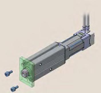
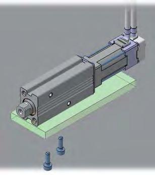
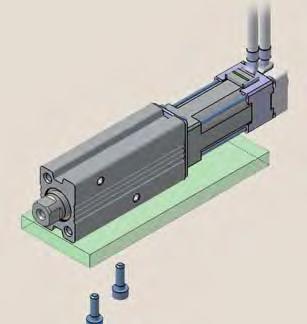
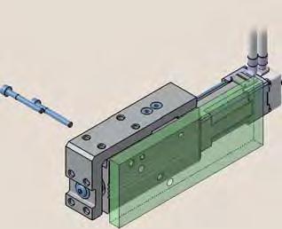
31 Warning Series LEPY/LEPS Specific Product Precautions Be sure to read before handling. Refer to back cover for Safety Instructions and the Operation Manual for Electric Actuator Precautions. Please download it via our website, Design/Selection. Do not apply a load in excess of the operating limit. A product should be selected based on the maximum load and allowable moment. If the product is used outside of the operating limit, eccentric load applied to the guide will become excessive and have adverse effects such as creating play on the sliding parts of the piston rod, degraded accuracy, operation and shortened product life. 2. Do not use the product in applications where excessive external force or impact force is applied to it. Do not apply impact and vibration outside of the specifications; it may lead to a malfunction.. If gravity acts on the workpiece due to vertical mounting, it may drop due to its own weight depending on the conditions when the product is not energized (SV signal is ) or stopped (EMG is not energized).. Power failure may result in a decrease in the pushing force; ensure that safety measures are in place to prevent injury to the operator or damage to the equipment. When the product is used for clamping, the clamping force could be decreased due to power failure, potentially creating a hazardous situation in which the workpiece is released.. This product cannot be used as a stopper. Excessive load acts on the actuator, which adversely affects the operation and the life. Warning Mounting. Do not drop or hit the actuator to avoid scratching and denting the mounting surfaces. Even slight deformation can cause the deterioration of accuracy and operation failure. 2. When mounting workpieces or jigs to the rod end, hold the flats of the rod end with a wrench so that the rod does not rotate (Rod type only). When attaching a bolt or workpiece to the end of the rod, hold the flats of the rod end with a wrench (the rod should be fully retracted). Do not apply tightening torque to the rod non-rotating mechanism. The rod is manufactured to precise tolerances, so even a slight deformation may cause a malfunction and damage (Rod type only). Warning Socket LEPY6 LEPY Mounting. When mounting a bolt, workpiece or jig to the rod end, the bolt should be tightened to a torque within the specified range (Rod type only). Tightening to a torque higher than the specified value may cause a malfunction due to deformation of the component, whilst under-tightening can cause displacement of the mounting position or in extreme conditions detaching of the workpiece. If the bolt is screwed in more than the maximum depth, the slide screw will be damaged, leading to operation failure (Rod type only). Rod Max. Max. Rod end Model Bolt tightening screw-in width across torque [N m] depth [mm] flats [mm] M x.7 M x.8... The angular position of the rod end flats cannot be changed because the rod has a non-rotating mechanism inside (Rod type only). The angular position of the rod end flats is not specified; it depends on the actuator type (Rod type only). The rod rotates slightly due to the clearance of the non-rotating mechanism: Install the bolt or workpiece with consideration to the rotation (Rod type only).. When attaching the workpiece to the table, hold the table and tighten the bolts to a torque within the specified range (Slide table only). The table is supported by a linear guide, do not apply impact or moment when mounting the workload. If the bolts are screwed to more than the maximum thread depth, it may lead to a malfunction due to damage of the linear guide or body. Top mounting Model LEPS6 LEPS Bolt M x.7 M x.7 Max. tightening torque [N m] Max. screw-in depth [mm] 6 6 LECP Model Selection LECP6 LEPS LEPY Specific Product Precautions Front mounting fixed Model LEPS6 LEPS Bolt M x.7 M x.7 Max. tightening torque [N m].. Max. screw-in depth [mm] 7 8 2
32 Series LEPY/LEPS Specific Product Precautions 2 Be sure to read before handling. Refer to back cover for Safety Instructions and the Operation Manual for Electric Actuator Precautions. Please download it via our website, Warning 6. Tighten the mounting screws within the specified torque range. Tightening with higher torque than the specified range may cause malfunction while the tightening with lower torque can cause the displacement of gripping position or dropping a workpiece. Mounting 8. When an external guide is used, connect it in such a way that no impact or load is applied to it. This may cause a malfunction due to an increase in sliding resistance, or use a freely moving connector (such as a floating joint). Side mounting (Body mounting through-hole) Model LEPY6 LEPS6 LEPY LEPS Side mounting (Body tapped) Model LEPY6 LEPS6 LEPY LEPS Bolt M x.7 M x.8 Bottom mounting (Body tapped) Model LEPY6 LEPS6 LEPY LEPS Bolt M x.7 M x.8 Rod side mounting (Rod type only) Model LEPY6 LEPY Bolt M x. M x.7 Bolt M x.7 M x.8 Max. tightening torque [N m].9 Max. tightening torque [N m] Max. screw-in depth [mm] When it is necessary to operate the product by the manual override screw, check the position of the manual override and leave necessary space for access. Do not apply excessive torque to the manual override screw. This may lead to damage and malfunction. 2.. Max. tightening torque [N m] Max. screw-in depth [mm].. Max. tightening torque [N m] Max. screw-in depth [mm] Caution Handling. When the pushing operation is used, be sure to set to [Pushing operation]. Also, do not hit the workpiece in positioning operation or in the range of positioning operation. It may damage and malfunction. If the operation is interrupted or stopped during the cycle: When the pushing operation command is output immediately after restarting the operation, the direction of movement depends on the position of restart. 2. Use within the specified pushing speed range for the pushing operation. It may lead to damage and malfunction. Model LEPY6 LEPS6 LEPY LEPS Lead 8 Pushing speed [mm/sec] 2 2. For the pushing operation, ensure that the force is applied in the direction of the rod axis.. The positioning force should be the initial value. If the positioning force is set below the initial value, it may cause an alarm. Model Motor size Positioning force [%] LEPY6 Basic LEPY Basic Compact. Actual speed of the product can be changed by load. When selecting a product, check the catalogue for the instructions regarding selection. 6. Do not scratch or dent the sliding parts of the piston rod, by striking or attaching objects. The rod is manufactured to precise tolerances, even a slight deformation may cause malfunction. 7. Avoid using the electric actuator in such a way that rotational torque would be applied to the rod. It may cause deformation of the non-rotating sliding part, leading to clearance in the internal guide or an increase in the sliding resistance. Refer to the table below for the approximate values of the allowable range of rotational torque. Allowable rotational LEPY6 LEPY torque [N m] or less..8
33 Caution 8. Do not operate by fixing the piston rod and moving the actuator body Excessive load will be applied to the rod, leading to damage to the actuator and reduced lifetime. 9. Return to origin ) Do not apply a load, impact or resistance in addition to the transferred load during return to origin. Additional force will cause the displacement of the origin position since it is based on detected motor torque. 2) When the return to origin is set with <Basic parameter> [Origin offset], it is necessary to change the current position of the product. Recheck the value of step data. ) It is recommended to set the directions of return to origin and pushing in the same direction in order to enhance the measurement accuracy during pushing operation.. There is no backlash effect in pushing operation. The return to origin is done by the pushing operation. The position can be displaced by the effect of the backlash during the positioning operation. Take the backlash into consideration when setting the position. <Backlash> Model LEPY6 LEPS6 LEPY LEPS Series LEPY/LEPS Specific Product Precautions Be sure to read before handling. Refer to back cover for Safety Instructions and the Operation Manual for Electric Actuator Precautions. Please download it via our website, Backlash [mm] ±. ±. ±. ±.. Do not hit the stroke end except for during the return to origin. This may damage the inner parts. 2. INP output signal ) Positioning operation When the product comes within the set range by step data [In position], the INP output signal will be turned on. Initial value: Set to [.] or higher. 2) Pushing operation When the effective pushing force exceeds the step data (trigger LV), the INP (In position) output signal is outputted. When [pushing force] setting and [trigger LV] are set below [pushing force], use the product within the specified range of [pushing force and trigger LV]. a) To ensure that the product pushes the workpiece with the set [pushing force], it is recommended that the [Trigger LV] is set to the same value as the [pushing force]. b) If the [trigger LV] is set lower than the [operation pushing force (current pushing force) for the pushing operation], the pushing force will exceed the trigger LV from the pushing start position and the INP output signal will be outputted before pushing the workpiece. Increase the pushing force, or change the workload so that the current pushing force becomes smaller than the Trigger LV. <Pushing force and trigger LV range> Model Motor size Set value of pushing force [%] LEPY6 LEPS6 Basic 7 to LEPY Basic to LEPS Compact 6 to Handling. In pushing operation, set the product to a position of at least. mm away from a workpiece. (This position is referred to as a pushing start position.) The following alarms may be generated and operation may become unstable. a. Posn failed alarm is generated. The product cannot reach a pushing start position due to variation in the width of workpieces. b. Pushing ALM alarm is generated. The product is pushed back from a pushing start position after starting to push. c. Deviation over flow alarm is generated. Displacement exceeding the specified value is generated at the pushing operation start position.. When pushing operating, operate within duty ratio range. The duty ratio is a ratio at the time that can keep being pushed. Model LEPY6 LEPS6 Model LEPY LEPS Model LEPY LEPS Motor size Basic Motor size Basic Motor size Compact Warning Set value of Continuous pushing pushing force [%] Duty ratio [%] time [minute] or less 7 Maintenance 7 Set value of pushing force [%] Duty ratio [%] 7 or less 8 Set value of Duty ratio [%] pushing force [%] 7. Ensure that the power supply is stopped and the workpiece is removed before starting maintenance work or replacement of the product. Continuous pushing time [minute] Continuous pushing time [minute] LECP Model Selection LECP6 LEPS LEPY Specific Product Precautions 22
34 2
 Series")
35 Step data input type Controller Page 2 Model Selection Step Motor (Servo/2 VDC) Series LECP6 Programless type Page Specific Product Precautions Step Motor (Servo/2 VDC) Series LECP 2
36 Controller (Step data input type) Series LECP6 How to Order RoHS LE C P 6 P Controller Compatible motor Step motor P (Servo/2 VDC) Number of step data (Points) 6 6 Parallel I/O type N NPN P PNP I/O cable length [m] Without cable. Actuator part number (Except cable specifications and actuator options) Example: Enter LEPYK- for the LEPYK-U-R6NI. Option D Note) Screw mounting DIN rail mounting Note) DIN rail is not included. Order it separately. When controller equipped type (-6N/-6P) is selected when ordering the LE series, you do not need to order this controller. The controller is sold as single unit after the compatible actuator is set. Confirm that the combination of the controller and the actuator is correct. <Check the following before use.> q Check the actuator label for model number matches the controller label. w Check that the Parallel I/O configuration matches (NPN or PNP). Refer to the operation manual for using the products. Please download it via our website, q w Specifications Basic Specifications Item Compatible motor Power supply Note ) Parallel input Parallel output Compatible encoder Serial communication Memory LED indicator Lock control Cable length [m] Cooling system Operating temperature range [ C] Operating humidity range [%RH] Storage temperature range [ C] Storage humidity range [%RH] Insulation resistance [MΩ] Weight [g] Specifications Step motor (Servo/2 VDC) Power voltage: 2 VDC ±% Current consumption: A (Peak A) Note 2) [Including motor drive power, control power, stop, lock release] inputs (Photo-coupler isolation) outputs (Photo-coupler isolation) Incremental A/B phase (8 pulse/rotation) RS8 (Modbus protocol compliant) EEPROM LED (Green/Red) one of each Forced-lock release terminal Note ) I/O cable: or less Actuator cable: 2 or less Natural air cooling to (No freezing) 9 or less (No condensation) to 6 (No freezing) 9 or less (No condensation) Between the housing (radiation fin) and SG terminal ( VDC) (Screw mounting) 7 (DIN rail mounting) Note ) Do not use the power supply of inrush current prevention type for the controller power supply. Note 2) The power consumption changes depending on the actuator model. Refer to the specifications of actuator for more details. Note ) Applicable to non-magnetizing lock. 2

 (2) 7. L 2. (Pitch)..2.2 Specific Product Precautions No.")
37 Controller (Step data input type)/ Series LECP6 How to Mount a) Screw mounting (LECP6-) (Installation with two M screws) b) DIN rail mounting (LECP6D-) (Installation with the DIN rail) Model Selection Mounting direction Ground wire Ground wire DIN rail DIN rail is locked. Ground wire Mounting direction A DIN rail mounting adapter Hook the controller on the DIN rail and press the lever of section A in the arrow direction to lock it. DIN rail AXT-DR- For, enter a number from the No. line in the table below. Refer to the dimensions on page 27 for the mounting dimensions. L Dimension [mm] () (2) 7. L 2. (Pitch)..2.2 Specific Product Precautions No. L No. L DIN rail mounting adapter LEC-D (with 2 mounting screws) This should be used when the DIN rail mounting adapter is mounted onto the screw mounting type controller afterwards. 26
38 Series LECP6 Dimensions a) Screw mounting (LECP6-) (8.7) 66 Power supply LED (Green) (: Power supply is.) ø. for body mounting Power supply LED (Red) (: Alarm is.) CN parallel I/O connector CN serial I/O connector CN encoder connector 2 CN2 motor power connector CN power supply connector.6 for body mounting b) DIN rail mounting (LECP6D-) (8.7) 66 (.) Refer to page 26 for L dimension and part number of DIN rail. 7.2 (When removing DIN rail) 67. (When locking DIN rail) (9.7) 27
39 Controller (Step data input type)/ Series LECP6 Wiring Example Power Supply Connector: CN Power supply plug is an accessory. Power supply plug for LECP6 Model Selection CN Power Supply Connector Terminal for LECP6 (PHOENIX CTACT FK-MC./-ST-2.) Terminal name Function Details V Common supply ( ) M2V terminal/c2v terminal/emg terminal/bk RLS terminal are common ( ). M2V Motor power supply (+) Motor power supply (+) supplied to the controller C2V Control power supply (+) Control power supply (+) supplied to the controller EMG Stop (+) Input (+) for releasing the stop BK RLS Lock release (+) Input (+) for releasing the lock Wiring Example 2 Parallel I/O Connector: CN Wiring diagram LECP6N- (NPN) CN COM+ COM IN IN IN2 IN IN IN SETUP HOLD DRIVE RESET SV OUT OUT OUT2 OUT OUT OUT BUSY AREA SET INP SVRE ESTOP ALARM A A2 A A A A6 A7 A8 A9 A A A2 A B B2 B B B B6 B7 B8 B9 B B B2 B When you connect a PLC, etc., to the CN parallel I/O connector, please use the I/O cable (LEC-CN-). The wiring should be changed depending on the type of the parallel I/O (NPN or PNP). Power supply 2 VDC for I/O signal Load LECP6P- (PNP) CN COM+ COM IN IN IN2 IN IN IN SETUP HOLD DRIVE RESET SV OUT OUT OUT2 OUT OUT OUT BUSY AREA SET INP SVRE ESTOP ALARM A A2 A A A A6 A7 A8 A9 A A A2 A B B2 B B B B6 B7 B8 B9 B B B2 B V M2V C2V EMG BK RLS Power supply 2 VDC for I/O signal Load Specific Product Precautions Input Signal Name COM+ COM IN to IN SETUP HOLD DRIVE RESET SV Details Connects the power supply 2 V for input/output signal Connects the power supply V for input/output signal Step data specified Bit No. (Input is instructed in the combination of IN to.) Instruction to return to the original position Operation is temporarily stopped Instruction to drive Alarm reset and operation interruption Servo instruction Output Signal Name Details OUT to OUT Outputs the step data no. during operation BUSY Outputs when the actuator is moving AREA Outputs within the step data area output setting range SET Outputs when returning to the original position Outputs when target position or target force is reached INP (Turns on when the positioning or pushing is completed.) SVRE Outputs when servo is on ESTOP Note) Not output when EMG stop is instructed ALARM Note) Not output when alarm is generated Note) Signal of negative-logic circuit (N.C.) 28
40 Series LECP6 Step Data Setting. Step data setting for positioning 2. Step data setting for pushing In this setting, the actuator moves toward and stops at the target position. The following diagram shows the setting items and operation. The setting items and set values for this operation are stated below. Speed Speed The actuator moves toward the pushing start position, and when it reaches that position, it starts pushing with less than the set force. The following diagram shows the setting items and operation. The setting items and set values for this operation are stated below. Speed Acceleration Deceleration Acceleration Deceleration Speed Position Pushing speed INP output In position Force Position In position Pushing force Trigger LV INP output Step Data (Positioning) : Need to be set. : Need to be adjusted as required. : Setting is not required. Step Data (Pushing) : Need to be set. : Need to be adjusted as required. Necessity Item Details Necessity Item Details Movement method Speed Position When the absolute position is required, set Absolute. When the relative position is required, set Relative. Transfer speed to the target position Target position Movement method Speed Position When the absolute position is required, set Absolute. When the relative position is required, set Relative. Transfer speed to the pushing start position Pushing start position Acceleration Parameter which defines how rapidly the actuator reaches the speed set. The higher the set value, the faster it reaches the speed set. Acceleration Parameter which defines how rapidly the actuator reaches the speed set. The higher the set value, the faster it reaches the speed set. Deceleration Parameter which defines how rapidly the actuator comes to stop. The higher the set value, the quicker it stops. Deceleration Parameter which defines how rapidly the actuator comes to stop. The higher the set value, the quicker it stops. Pushing force Trigger LV Pushing speed Positioning force Area, Area 2 In position Set. (If values to are set, the operation will be changed to the pushing operation.) Setting is not required. Setting is not required. Max. torque during the positioning operation (No specific change is required.) Condition that turns on the AREA output signal. Condition that turns on the INP output signal. When the actuator enters the range of [in position], the INP output signal turns on. (It is unnecessary to change this from the initial value.) When it is necessary to output the arrival signal before the operation is completed, make the value larger. Pushing force Trigger LV Pushing speed Positioning force Pushing force ratio is defined. The setting range differs depending on the electric actuator type. Refer to the operation manual for the electric actuator. Condition that turns on the INP output signal. The INP output signal is turned on when the generated force exceeds the value. Threshold level should be less than the pushing force. Pushing speed When the speed is set fast, the electric actuator and work pieces might be damaged due to the impact when they hit the end, so this set value should be smaller. Refer to the operation manual of the electric actuator. Max. torque during the positioning operation (No specific change is required.) Area, Area 2 Condition that turns on the AREA output signal. In position Transfer distance during pushing. If the transferred distance exceeds the setting, it stops even if it is not pushing. If the transfer distance is exceeded, the INP output signal will not be turned on. 29
41 Controller (Step data input type)/ Series LECP6 Signal Timing Return to Origin Power supply SV Input SETUP BUSY SVRE SET Output INP ALARM 2 V V Model Selection ESTOP Speed mm/s Return to origin If the actuator is within the in position range of the basic parameter, INP will be turned, but if not, it will remain. ALARM and ESTOP are expressed as negative-logic circuit. Positioning Operation Input IN DRIVE ms or more Scan the step data no. Output the step data no. Pushing Operation Input IN DRIVE ms or more Scan the step data no. Output the step data no. Output OUT BUSY INP Output OUT BUSY INP Specific Product Precautions Speed Positioning operation mm/s Speed Pushing operation mm/s If the actuator is within the in position range of the step data, INP will be turned, but if not, it will remain. If the current pushing force exceeds the trigger LV value of the step data, the INP signal will be turned. OUT is output when DRIVE is changed from to. (When power supply is applied, DRIVE or RESET is turned or ESTOP is turned, all of the OUT outputs are turned.) HOLD Input Output HOLD BUSY Speed Slow-down starting point HOLD during the operation When the actuator is in the positioning range in the pushing operation, it does not stop even if HOLD signal is input. mm/s Reset Input Output RESET OUT ALARM Alarm out Alarm reset ALARM is expressed as negative-logic circuit. It is possible to identify the alarm group by the combination of OUT signals when the alarm is generated.
42 Series LECP6 Options: Actuator Cable, I/O Cable Actuator cable [Robotic cable, standard cable for step motor (servo/2 VDC)] LE-CP- /Cable length:. m, m, m LE CP Cable length(l)[m]. 8 8 A B C 2 Produced upon receipt of order (Robotic cable only) S Cable type Robotic cable (Flexible cable) Standard cable (Terminal no.) () (Terminal no.) 2 6 (.) 2 6 () Actuator side (.) (7.7) (7.7) Signal A A B B COM-A/COM COM-B/ Vcc GND A A B B (.7) Actuator side (ø8) Connector A 8 LE-CP- A B C/Cable length: 8 m, m, m, 2 m ( Produced upon receipt of order) (ø6.) (ø.) Connector C Controller side (.2) L Connector D () Connector C (.2) Connector A (.7) L Connector D () Connector A terminal no. B- A- B-2 A-2 B- A- B- A- B- A- B-6 A-6 Shield () (8) Controller side () (8) Connector C Cable colour terminal no. Brown 2 Red Orange 6 Yellow Green Blue Connector D Cable colour terminal no. Brown 2 Black Red 7 Black 6 Orange 9 Black 8 (Terminal no.) A B A6 B6 (.7) (Terminal no.) A B A6 B6 (.7) I/O cable LEC CN Cable length(l)[m]. Controller side (22.) (ø8.9) (.) L PLC side A A B B (Terminal no.) B A B A Conductor size: AWG28 Connector Insulation pin no. colour A Light brown A2 Light brown A Yellow A Yellow A Light green A6 Light green A7 Grey A8 Grey A9 White A White A Light brown A2 Light brown A Yellow Dot mark Dot colour Black Red Black Red Black Red Black Red Black Red Black Red Black Connector pin no. B B2 B B B B6 B7 B8 B9 B B B2 B Insulation colour Yellow Light green Light green Grey Grey White White Light brown Light brown Yellow Yellow Light green Light green Dot mark Shield Dot colour Red Black Red Black Red Black Red Black Red Black Red Black Red

43 HRS Series LEC Controller Setting Kit/LEC-W2 How to Order Model Selection LEC W2 w Communication cable e USB cable (A-mini B type) q Controller setting software PC Controller setting kit (Japanese and English are available.) Contents q Controller setting software (CD-ROM) w Communication cable e USB cable (Cable between the PC and the conversion unit) Hardware Requirements PC/AT compatible machine installed with Windows XP and equipped with USB. or USB2. ports. Windows and Windows XP are registered trademarks of Microsoft Corporation. Screen Example Easy mode screen example Normal mode screen example Specific Product Precautions Easy operation and simple setting Allowing to set and display actuator step data such as position, speed, force, etc. Setting of step data and testing of the drive can be performed on the same page. Can be used to jog and move at a constant rate. Detailed setting Step data can be set in detail. Signals and terminal status can be monitored. Parameters can be set. JOG and constant rate movement, return to origin, test operation and testing of forced output can be performed. 2
![Series LEC Teaching Box/LEC-T How to Order RoHS Enable switch (Option) LEC T E G Teaching box Cable length [m] Enable switch None S Equipped with enable switch Interlock switch for jog and test](/docs-images/84/89195649/images/44-0.jpg "function Stop switch Initial language J Japanese E English Stop switch G Equipped with stop switch Specifications Standard functions Option Item Switch Cable length [m] Enclosure Operating")
44 Series LEC Teaching Box/LEC-T How to Order RoHS Enable switch (Option) LEC T E G Teaching box Cable length [m] Enable switch None S Equipped with enable switch Interlock switch for jog and test function Stop switch Initial language J Japanese E English Stop switch G Equipped with stop switch Specifications Standard functions Option Item Switch Cable length [m] Enclosure Operating temperature range [ C] Operating humidity range [%RH] Description Stop switch, Enable switch (Option) IP6 (Except connector) to 9 or less (No condensation) Weight [g] (Except cable) Note) CE-compliance The EMC compliance of the teaching box was tested with the LECP6 series step motor controller (servo/2 VDC) and an applicable actuator. Easy Mode Function Step data Jog Test Monitor ALM TB setting Details from Position, Speed, Force. Menu Operations Flowchart Menu Data Monitor Jog Test ALM TB setting Data Step data no. Setting of two items selected below (Position, Speed, Force, Acceleration, Deceleration) Monitor (Position, Speed, Force) Jog Jog operation Test ALM Alarm reset TB setting Set item
45 Teaching Box Series LEC Normal Mode Function Step data Parameter Test Monitor ALM File TB setting Reconnect Details movement (Specify a maximum of step data and operate.) (Forced signal output, Forced terminal output) (Alarm reset) Save the step data and parameters of the controller which is being used for communication (it is possible to save four files, with one set of step data and parameters defined as one file). Loads the data which is saved in the teaching box to the controller which is being used for communication. Menu Operations Flowchart Menu Step data Step data Step data no. Parameter Movement method Monitor Speed Test Position ALM Acceleration File Deceleration TB setting Pushing force Reconnect Trigger LV Pushing speed Positioning force Area, 2 Parameter Basic Monitor Drive Output signal Output terminal Test Test drive Forced output ALM Status ALM Log record File Data saving Load to controller File deletion TB setting Language Backlight LCD contrast Beep Max. connection axis Password Distance unit Basic setting ORIG setting DRV monitor Position, Speed, Torque Step no. Last step no. Output signal monitor Input signal monitor Output terminal monitor Input terminal monitor Status Active alarm display Alarm reset ALM Log record display Log entry display Model Selection Specific Product Precautions Reconnect Dimensions q y u 2 i e w 8 t. r No Description LCD Ring Stop switch Stop switch guard Enable switch (Option) Key switch Cable Connector Function A screen of liquid crystal display (with backlight) A ring for hanging the teaching box When switch is pushed in, the switch locks and stops. The lock is released when it is turned to the right. A guard for the stop switch Prevents unintentional operation (unexpected operation) of the jog test function. Other functions such as data change are not covered. Switch for each input Length: meters A connector connected to CN of the controller
![Programless Controller Series LECP RoHS How to Order P LEC P P Controller Compatible motor Step motor (Servo/2 VDC) I/O cable length [m] Without cable.](/docs-images/84/89195649/images/46-0.jpg "Number of step data (Points) (Programless) Parallel I/O type N P NPN PNP LEPY- Actuator part number (Except cable specifications and actuator options) Example: Enter LEPYK- for the LEPYK-U-R6NI.")
46 Programless Controller Series LECP RoHS How to Order P LEC P P Controller Compatible motor Step motor (Servo/2 VDC) I/O cable length [m] Without cable. Number of step data (Points) (Programless) Parallel I/O type N P NPN PNP LEPY- Actuator part number (Except cable specifications and actuator options) Example: Enter LEPYK- for the LEPYK-U-R6NI. When controller equipped type (-N/-P) is selected when ordering the LE series, you do not need to order this controller. The controller is sold as single unit after the compatible actuator is set. Confirm that the combination of the controller and the actuator is correct. Refer to the operation manual for using the products. Please download it via our website, Specifications Basic Specifications Item Compatible motor Note ) Power supply Parallel input Parallel output Stop points Compatible encoder Serial communication Memory LED indicator 7-segment LED display Note ) Lock control Cable length [m] Cooling system Operating temperature range [ C] Operating humidity range [%RH] Storage temperature range [ C] Storage humidity range [%RH] Insulation resistance [MΩ] Weight [g] Specifications Step motor (Servo/2 VDC) Power supply voltage: 2 VDC ±% Max. current consumption: A (Peak A) Note 2) [Including the motor drive power, control power supply, stop, lock release] 6 inputs (Photo-coupler isolation) 6 outputs (Photo-coupler isolation) points (Position number to (E)) Incremental A/B phase (8 pulse/rotation) RS8 (Modbus protocol compliant) EEPROM LED (Green/Red) one of each digit, 7-segment display (red) Figures are expressed in hexadecimal ( to in decimal number are expressed as A to F ) Forced-lock release terminal Note ) I/O cable: or less Actuator cable: 2 or less Natural air cooling to (No freezing) 9 or less (No condensation) to 6 (No freezing) 9 or less (No condensation) Between the housing (radiation fin) and SG terminal ( VDC) Note ) Do not use the power supply of inrush current prevention type for the controller input power supply. Note 2) The power consumption changes depending on the actuator model. Refer to the each actuator s operation manual etc. for details. Note ) to in decimal number are displayed as follows in the 7-segment LED. Decimal display Hexadecimal display A b 2 c d E F Note ) Applicable to non-magnetizing lock.
240 g. 290 g. Electric Actuators. Compact and lightweight. New. Series LEPY/LEPS. Offering 2 types of controller
 Electric Actuators Miniature Rod Type Compact and lightweight Rod Type Series LEPY Miniature Slide Table Type RoHS Maximum pushing force: N Positioning repeatability:. mm Possible to set position, speed
240 g. 290 g. Compact and lightweight. Electric Actuators. LEPY/LEPS Series. Miniature Rod Type/Miniature Slide Table Type
 Electric Actuators LEPY/LEPS Series Miniature Rod Type/Miniature Slide Table Type Compact and lightweight Rod Type LEPY Series Weight 24 g LEPY6-25 3 mm 2.5 mm Slide Table Type LEPS Series Weight 29 g
240 g. 290 g. Compact and lightweight. Electric Actuators. Series LEPY/LEPS. Miniature Rod Type/Miniature Slide Table Type
 Electric ctuators Series LEPY/LEPS Miniature Rod Type/Miniature Slide Table Type Step Motor (Servo/2 VDC) and lightweight Rod Type Series LEPY Weight 2 g LEPY6-2 RoHS Maximum pushing force: N Positioning
240 g. 290 g. Electric Actuators Series LEPY/LEPS. Miniature Rod Type/Miniature Slide Table Type
 Electric Actuators Series / Miniature Rod Type/Miniature Slide Table Type RoHS Compact and lightweight Rod Type Series Weight 24 g 6-25 Maximum pushing force: 5 N Positioning repeatability:.5 mm Possible
Electric Rotary Table
 Electric Rotary Table New RoHS H Low profile Basic type [mm] Model H LER 42 LER LER High precision type [mm] Model H LERH 49 LERH 2 LERH 7 Spacesaving Hollow shaft axis Accommodates wiring and piping of
Basic and high precision types are available.
 Series RoHS Model H 1 3 5 42 Rotation angle: 36 Page 47 LEJS LEJB type [mm] Continuous rotation specification LEL Low profile LEFS LEFB 53 68 H 49 LEY LEYG Model H1 H3 H5 LEM High precision type [mm] 62
Electric Rotary Table
 Electric Rotary Table Series LER RoHS H Step Motor (Servo/24 VDC) Low profile New Continuous Basic type [mm] rotation Model H specification LER1 42 LER3 53 LER5 68 High precision type [mm] Model H LERH1
Electric Actuator/Slider Type Motor Parallel Type
 INFORMATION Electric Actuator/Slider Type Motor Parallel Type RoHS Reduced in overall length Parallel Reduced dimension Reduced in height Reduced dimension Parallel In-line In-line Size Length reduction
Electric Actuator Controller/Driver
 Slider Series LEF Electric Actuator Controller/Driver Slider /High Rigidity Series LEJ Guide Rod Slider Series LEL P.1 P.2 P.3 Slider / Low Profile Series LEM Rod Series LEY Slide Table Series LES P.4
Electric Rotary Table
 Electric Rotary Table Series RoHS Model H 1 3 5 42 Rotation angle: 36 Page 47 53 68 H 49 G Model H1 H3 H5 High precision type [mm] 62 78 Max. speed: 42 /sec (7.33 rad/sec) Max. acceleration/deceleration:
Electric Rotary Table
 Electric Rotary Table LER Series H Low profile [mm] Model H LER1 42 LER3 53 LER5 68 High precision [mm] Model H LERH1 49 LERH3 62 LERH5 78 Continuous rotation specification RoHS Rotation angle: 36 Pages
Electric Actuator. New. New. Long stroke: Max. 500 mm (LEY32)
") Electric ctuator Rod Type Guide Rod Type New Step otor (Servo/ VDC) Servo otor ( VDC) Type Rod Type Series LEY :,, Long stroke: ax. 00 mm (LEY) ounting variations Direct mounting: directions, Bracket mounting:
Electric ctuator Rod Type Guide Rod Type New Step otor (Servo/ VDC) Servo otor ( VDC) Type Rod Type Series LEY :,, Long stroke: ax. 00 mm (LEY) ounting variations Direct mounting: directions, Bracket mounting:
Electric Rotary Table Series LER
 Electric Rotary Table Series RoHS Low profile type [mm] Model H 1 42 3 53 5 68 Continuous rotation tion Rotation angle: 36 Page 47 H High precision type [mm] Model H H1 49 H3 62 H5 78 H G Shock-less/High
Problems programming your electric actuator?
 SMC solutions electric actuators Problems programming your electric actuator? Easy setting electric actuators delivering outstanding speed, force and positioning control Electric Actuators Speed, Force
Information. Model LEYG16 LEYG25 LEYG32
 Information A rod type with guide newly added! Compatible with slide-bearing and ball-bushing bearing. Compatible with moment load and stopper (slide bearing). Speed control/positioning: ax. points Positioning
Information. Electric Slide Table/In-line Motor Type. Series LESH D. In-line motor type newly added to electric slide table! Reduced cycle time
 Information Electric Slide Table/In-line Motor Type Series ESHD In-line type newly added to electric slide table! Width dimension shortened by up to % kihabara UDX F, --, Sotokanda, Chiyoda-ku, Tokyo 0-00,
Electric Actuator. New. New. Long stroke:
 Electric ctuator Rod Type Step otor (Servo/2 VDC) Long stroke: Guide Rod Type Rod Type Series LEY ax. 00 mm (LEY) ounting variations Direct mounting: directions, Bracket mounting: types uto switch can
Information. Electric Slide Table/In-line Motor Type. Series LESH D. In-line motor type newly added to electric slide table!
 Information kihabara UDX F, --, Sotokanda, Chiyoda-ku, Tokyo 0-00, PN UR http://www.smcworld.com 0 SMC Corporation ll Rights Reserved Electric Slide Table/In-line Motor Type Series ESHD In-line type newly
Type. Rod type. Auto switch mountable. Guide rod type. Size: 25, 32, 63 Note) Size: 25, 32. Rod type/ In-line motor type. Driver.
 Size: 25, 32. Rod type/ In-line motor type. Driver.") Electric ctuators Rod Type Guide Rod Type New RoHS Step Motor (Servo/ VDC) Rod Type Series Long stroke: Max. 00 mm (, ) Servo Motor ( VDC) Mounting variations Direct mounting: directions, racket mounting:
Electric ctuators Rod Type Guide Rod Type New RoHS Step Motor (Servo/ VDC) Rod Type Series Long stroke: Max. 00 mm (, ) Servo Motor ( VDC) Mounting variations Direct mounting: directions, racket mounting:
Electric Actuator/ Guide Rod Type
 ourtesy of M/Flodyne/Hydradyne Motion ontrol Hydraulic Pneumatic Electrical Mechanical (800) 426-5480 www.cmafh.com Size How to Order LEYG M B 50 S N1 Bearing type M Sliding bearing L Ball bushing bearing
Electric Actuator. New. Low-profile/Low center of gravity. Series LEJ CAT.ES A. Slider Type. High Rigidity. Ball Screw Drive Series LEJS
 Electric Actuator High Rigidity Slider Type New RoHS Low-profile/Low center of gravity Height dimension reduced by approx. 31% (Reduced by 28 mm) LJ1H2 Series New LEJS4 (Existing model) LJ1H2 Work load
Electric Actuator Series LEL
 Electric Actuator Series LEL Guide Rod Slider RoHS LEFS LEFB Low-profile/Flat Height 48 mm Profile reduced by side mounting of motor DOWN LEL25 48 mm Max. stroke: 1 mm Transfer speed: 1 mm/s LEFB25 115.8
Environment Clean Room Specification
 Environment Clean Room Specification ISO Class 4 *1 (ISO14644-1) Built-in vacuum piping Possible to mount the main body without removing the external cover etc. Body-integrated linear guide specification
LJ1H LEJS40 AC
 Low-profile/Low center of gravity Height dimension reduced by approx. 36% (Reduced by 32 mm) 9 Electric Actuator LEJ Series Slider Type/High Rigidity 58 (Former model) LJ1H2 3 5 1 LJ1H2 LEJS4 RoHS Series
Type. Page 518. A support guide is designed to support workpieces with significant overhang.
 Environment Clean Room Specification ISO Class 4 *1 (ISO14644-1) Built-in vacuum piping Possible to mount the main body without removing the external cover etc. Body-integrated linear guide specification
Electric Actuator / Rod Type
 Doc. no. LEY-OM00206 PRODUCT NAME Electric Actuator / Rod Type MODEL / Series LEY Series Applicable models: LEY[], LEYG[], LEY Series (Rod type) LEYG Series (Guide Rod type) LEC Series Contents
Compact Slide. Series MXH ø6, ø10, ø16, ø20
 Compact Slide Series ø, ø, ø, ø The use of an endless track linear guide produces a table cylinder having excellent rigidity, linearity and non-rotating accuracy. Endless track linear guide Series Variations
Electric Slide Table
 Doc. no. LES-OM00213 PRODUCT NAME Electric Slide Table MODEL / Series / Product Number LES Series Applicable models: LES[]R,LES[]L,LES[]D,LESH[]R,LESH[]L,LESH[]D R Type Standard /LES[]R Series L Type Standard
240% 19% reduced. Compact Slide. MXH Series. Improved by up to. With new high rigidity linear guide. 369g. ø6, ø10, ø16, ø g.
 Compact Slide Series ø, ø, ø, ø RoHS Allowable moment MXS Improved by up to MXQ MXQ 2% MXF MXW MXJ MXP MXY With new high rigidity linear guide MTS Allowable moment improvement illustrated below Allowable
Your motor and driver can be used together! Manufacturers of compatible motors: 8 companies. Ball screw drive. Series LEJS. Size
 Motorless Type Electric Actuators New RoHS Your motor and driver can be used together! Manufacturers of compatible motors: companies Mitsubishi Electric Corporation SANYO DENKI CO., LTD. Panasonic Corporation
Electric Actuators. New. Motorless Type. Series LE. Your motor and driver can be used together! Manufacturers of compatible motors: 8 companies
 Motorless Type Electric Actuators New RoHS Your motor and driver can be used together! Manufacturers of compatible motors: companies Mitsubishi Electric Corporation SANYO DENKI CO., LTD. Panasonic Corporation
How to Order. Lead wire length Nil L Z M9N L. Type of auto switch for detecting rotation. Nil Without auto switch. Applicable Auto Switch
 Indicator light Indicator light Rotary Gripper Series MRHQ Size:, 1,, 25 How to Order Lead wire length Nil L Z.5 m 3 m 5 m MRH Q D 9 S M9NV L M9N L Q Rotary gripper Gripper Parallel type: 2 fingers D S
Precision Cylinder. MTS Series. ø8, ø12, ø16, ø20, ø25, ø32, ø40 MXH MXS MXQ MXQ MXF MXW MXJ MXP MXY MTS D- -X. Series Variations MTS8
 Precision Cylinder Series, ø, ø6, ø, ø, ø, ø MXS Series Variations Model 8 Standard stroke (mm) 7 7 Rod end configuration Cushion Rubber bumper End lock Made to Order Rod Variable stroke/ through-hole
Series LECSB. Series LECSA. Series LECSC. Series LECSS. AC Servo Motor Driver. Pulse Input Type. Pulse Input Type/ Positioning Type.
 AC Servo Motor Driver Series LECS Pulse Input Type/ Positioning Type Pulse Input Type Incremental Type Series LECSA LEF AbsoIute Type Series LECSB CC-Link Direct Input Type SSCNET # Type Absolute Type
Electric Actuator /Slider Type
 Doc. no. LEF-OM00201 PRODUCT NAME Electric Actuator /Slider Type MODEL / Series LEF Series LEC Series Contents Safety Instructions... 2 1. Procedure before operation/simple setting to use
Information. Electric Actuator/Rod Type. Added size 63 to the LEY series! Series LEY AC Servo Motor (400 W) Size: 63. RoHS
 Size: 63. RoHS") Information SC Corporation Akihabara UDX 1F, 4-14-1, Sotokanda, Chiyoda-ku, Tokyo 1-21, JAPAN http://www.smcworld.com 12 SC Corporation All Rights Reserved Electric Actuator/Rod Type Series EY AC Servo
Information SC Corporation Akihabara UDX 1F, 4-14-1, Sotokanda, Chiyoda-ku, Tokyo 1-21, JAPAN http://www.smcworld.com 12 SC Corporation All Rights Reserved Electric Actuator/Rod Type Series EY AC Servo
180 Angular Style Air Gripper
 8 Angular Style Air Gripper Series 2/2 Cam Style / Rack & Pinion Style 99 8 Angular Style Air Gripper Cam Style Rack & Pinion Style Series 2/2 Series 2/Cam Style Light and compact size in small bore sizes
Low Profile Air Gripper. Series MHF2. Low profile air gripper with space-saving design is newly released. 5-77
 Low Profile Air Gripper Low profile air gripper with space-saving design is newly released. 5-77 Low Profile Air Gripper Height is approximately / the size of an equivalent Series MHZ2. MHZ2-D 42 Bore
Type. Page 518. A support guide is designed to support workpieces with significant overhang.
 Environment Clean Room Specification ISO Class 4 *1 (ISO14644-1) Built-in vacuum piping Possible to mount the main body without removing the external cover etc. Body-integrated linear guide specification
RoHS Directive-Compliant Motorized Linear Slides EZS Series for Clean Room Use. Features
 Motorized Actuators RoHS Directive-Compliant Series for Clean Room Use The Series for Clean Room Use is a product designed with the same level of function and performance as the Series but is ideal for
Miniature Guide Rod Cylinder ±0.1. Mounting from 2 directions
 Miniature Guide Rod Cylinder Series Non-rotating accuracy : Height ±0.1 Mounting from 2 directions idth Overall length Two auto switches can be mounted even for mm strokes Integral wiring/piping to one
How to Order M9BW. Action. Double acting Single acting. Load voltage Electrical entry direction M9NWV M9NW 12 V 5 V, M9BWV M9BW 12 V 12 V
 Angular Type Air Gripper/Standard Type 2 Series ø, ø1, ø20, ø25 How to Order Angular type air gripper 2 20 Bore size mm 1 1 mm 20 20 mm 25 25 mm D S Action D Double acting Single acting M9BW Made to Order
Rotary Table/Vane Style
 Rotary Table/Vane Style Series Size: 1, 3, 7, 20 Table top deflection mm or less High Precision Peripheral table deflection mm or less X Series B Series A 147 Rotary Table Values inside ( ) are for Series
Electric Actuator / Rod Type
 Doc. no. LEYOM00402 PRODUCT NAME Electric Actuator / Rod Type AC Servo Motor MODEL / Series LEY Series Applicable models: LEY, LEYG LEY Series (Rod type) LEYG Series (Guide Rod type) AC Servo Motor Driver
Low Profile Air Gripper
 Low Profile Air Gripper Series MHF2 MHZ MHF MHL MHR MHK MHS MHC MHT MHY MHW -X Low profile air gripper with space-saving design MRHQ MA D- Courtesy of Steven ngineering, Inc.-2 Ryan Way, South San Francisco,
Angular Style Air Gripper
 Angular Style Air Gripper Series /A/M 15 Angular style air gripper Series /A/M - Auto switch is attachable. 8 mm x 0 mm x mm g Body option (Only for A-) Side piping Port Port A- Short body. 1 mm x 0 mm
Low Profile Air Gripper
 Low Profile Air Gripper MHF2 Series ø8, ø, ø, ø RoHS Low profile air gripper with space-saving design MHZ MHF MHL MHR MHK MHS MHC MHT MHY MHW -X MRHQ MA D- 465 Low Profile Air Gripper MHF2 Series Height
: 660 N. For material handling and clamping of small workpieces. CKZT25 -X2797 (Base Type) Power Clamp Cylinder INFORMATION. ø
 Power Clamp Cylinder INFORMATION. ø") For material handling and clamping of small workpieces INFORMATION Power Clamp Cylinder ø25 Compact Type 34 mm Lightweight Compact High clamping force Lock function 53 mm Lightweight Weight : 580 g Compact
For material handling and clamping of small workpieces INFORMATION Power Clamp Cylinder ø25 Compact Type 34 mm Lightweight Compact High clamping force Lock function 53 mm Lightweight Weight : 580 g Compact
Wedge Cam Operation Slide Guide. Air Gripper/2-Finger Type ø12, ø16, ø20, ø25. Option: Stainless steel
 Wedge Cam Operation Slide Guide Air Gripper/2-inger Type ø2, ø, ø, ø2 MH MH oad Resistant, Dust Cover for Adverse Environments 2 types of finger materials types of dust cover materials Standard: Carbon
Electric Actuator Rod Type
 Electric ctuator Rod Type Guide Rod Type New Step otor (Servo/2 VDC) Servo otor (2 VDC) Type Rod Type Series EY :,, ong stroke: ax. 00 mm (EY) ounting variations Direct mounting: directions, Bracket mounting:
Series MSU. Rotary Table Vane Style. High Precision. Size: 1, 3, 7, 20 CRB2 CRBU2 CRB1 MSU CRJ CRA1 CRQ2 MSQ MRQ D mm or less.
 Rotary Table Vane Style Series Size: 1, 3, 7, 20 Table top deflection mm or less High Precision Peripheral table deflection mm or less Series B Series A 11-5-1 Rotary High precision type Size: 1, 3, 7,
Guide Table. MGF Series
 Guide Table MGF Series ø, ø, ø0 Low-profile compact cylinder utilizes a large concentric guiding sleeve to provide excellent eccentric load resistance. Mounting height greatly reduced Low-profile cylinder
Rotary Actuated Air Gripper
 Rotary ctuated ir Gripper MHR, MDHR/MHR3, MDHR3 -finger type: Size, 15,, 3/ 3-finger type: Size, 15 High Precision - Repeatability ±.1 mm Parallel opening and closing mechanism utilizing a cross roller
Suitable for conveyor lines without an air supply
 Contact our sales office regarding a delivery date or a price since this is a special model. P107X-011E P: OW P.G.Information (pecialized product) Electric topper Cylinder LEBQ eries MC CORPORATION 4-14-1,
MULTI SLIDERS CONTENTS
 CAD drawing data catalog is available. ACTUATORS GENERAL CATALOG CONTENTS Features 923 Handling Instructions and Precautions 925 Specifications 929 Order Codes 930 Inner Construction 931 Dimensions 932
Rotary Table/Vane Style
 Rotary Table/Vane Style Series MSU Size: 1, 3, 7, 20 Table top deflection mm or less High Precision Peripheral table deflection mm or less CRB2 CRBU2 CRB1 MSU CRJ CRQ2 MSQ MSZ CRQ2X MSQX MRQ Series MSUB
Electric Actuator/ Rod Type
 How to Order LEY B 30 S N1 Lead Symbol LEY LEY LEY/ 10 12 B 5 6 8 2.5 3 4 otor option Nil Without option With motor cover B With lock W With lock/motor cover When With lock or With lock/motor cover are
Parallel Style Air Gripper: Wide Type
 Parallel Style Air Gripper: Wide Type Series MHL Built-in dust-protection mechanism A scraper with a dust lip is adopted for all rod rotating parts. A large amount of gripping force is provided through
Motion in your power Electric Actuators LE Series, JXC Series. Quick Overview
 Motion in your power Electric Actuators LE Series, JXC Series Quick Overview Electric Actuators LE Series, JXC Series RoHS Motion in your power ADAPTABILITY You decide - They adapt Electric actuators
Guide Table. ø40, ø63, ø100
 Guide Table Series MGF ø, ø, ø Low-profile compact cylinder utilizes a large concentric guiding sleeve to provide excellent eccentric load resistance. Mounting height greatly reduced Low-profile cylinder
ELECYLINDER. Battery-less Absolute Encoder No Battery, No Maintenance, No Homing, No Going Back to Incremental.
 EC Battery-less Absolute Encoder No Battery, No Maintenance, No Homing, No Going Back to Incremental. www.intelligentactuator.com Simple Simple Simple 555 Working Working Workingjust just just minutes
Linear & Rotary Actuators F-41
 & F-41 & DRS Series Equipped Page Series Equipped F-4 F-41 F-4 Series Equipped $ $ For detailed information about regulations and standards, please see the Oriental Motor website. The Series is a line
ROBO Cylinder Rotary Straight Motor Model 64mm Width 200V Servo Motor I N T P O. Notes on Selection. Deceleration Rated torque
 Slider RCS2 Cylinder RCS2-RT6 SA4D : Aluminum base SS4D : Steel base Cylinder Rotary Straight Model mm Width 200V Configuration: RCS2 RT6 I 60 18 L Series Encoder Deceleration Ratio Compatible Cable Length
Series MHK2. Wedge Cam Operation Slide Guide Air Gripper (2 Finger)
") Wedge Cam Operation lide Guide Air Gripper (2 inger) ø2, ø, ø2, ø2 oad Resistant, Dust Cover for Adverse Environments 2 types of finger materials types of dust cover materials tandard: Carbon steel Optional:
Wedge Cam Operation lide Guide Air Gripper (2 inger) ø2, ø, ø2, ø2 oad Resistant, Dust Cover for Adverse Environments 2 types of finger materials types of dust cover materials tandard: Carbon steel Optional:
49.5 mm Overall. 30 mm MXZ ø20. Compact. Compact Cylinder with Linear Guide. MXZ Series CAT.ES20-236A. ø12, ø16, ø20, ø25. MXZ ø20, 10 mm stroke.
 Compact Cylinder with Linear Guide ø12, ø16, ø20, ø25 RoHS Compact 49.5 mm Overall length MXZ ø20, 10 mm stroke 30 mm MXZ ø20 Width Design and assembly time is reduced due to integration of a linear guide
Advanced "Positioning" is in your hand.
 AZ Series Equipped Motorized Linear Slides Motorized Cylinders EAC Series / AZ Series Equipped Motorized Linear Slides Motorized Cylinders EAC Series / Lineup Added Battery-free Absolute Sensor Equipped
Space-saving installation Flexible motor mounting
 Space-saving installation Flexible motor mounting compatible!! Pulse train input compatible Automatic actuator recognition Addition of new controller compatible with pulse trains Enables current position
Series MXH/ ø6, ø10, ø16, ø20
 Compact Slide Series / ø, ø, ø, ø The use of an endless track linear guide produces a table cylinder having excellent rigidity, linearity and non-rotating accuracy. CL MLG CNA CNG MNB CNS CLS CB CV/MVG
Specifications MHC2-10D MHC2-16D MHC2-20D MHC2-25D MHC2-10S. Double acting MHC2-16S. Single acting MHC2-20S MHC2-25S. Angular style air gripper
 Angular Style Air Gripper Standard Type Series MHC2 Size: 10, 16, 20, 25 A large amount of gripping force is provided through the use of a double piston mechanism, while maintaining a compact design. Built-in
RCP5 Series ABSOLUTE. obo c y linde r. d e. RoboCylinder with Standard Battery-less Absolute Encoder
 GB RoboCylinder with Standard Battery-less Absolute Encoder RCP Series ABSOLUTE www.r obo c y linde r. d e Introducing the RCP series actuator with battery-less absolute encoder, realizing the convenience
Series MSU. Rotary Table. High Precision. Vane Type/Sizes 1, 3, 7, 20. High precision series MSUA introduced to vane type rotary tables CAT.
 CAT.ES20-90 C Rotary Table Series MSU Vane Type/Sizes 1, 3, 7, 20 Peripheral table deflection Table top deflection mm or less High Precision mm or less Series MSUB Series MSUA High precision series MSUA
R-SERIES MULTI-AXIS INDUSTRIAL ROBOTS
 Automation Solutions R-SERIES MULTI-AXIS INDUSTRIAL ROBOTS COMPACT MULTI-AXIS INDUSTRIAL ROBOTS FOR COMPLEX PROCESSING TASKS Reduce Manufacturing Costs Improve Production Time Increase Throughput Engineering
Solenoid Gripper GRS.
 Solenoid Gripper GRS www.intelligentactuator.com Small, affordable, easy to operate! The new Solenoid Gripper 1 Small size Compact and lightweight electric gripper that fits in the palm of the hand. 2
Hollow Rotary RCP6-RTFML.
 Hollow Rotary RCP6-RTFML www.intelligentactuator.com Slim and lightweight RCP6-RTFML Rotary with large-diameter hollow shaft of φ49, suitable for combined axes, is now available 1 f49 large-diameter hollow
Traveling parallelism: mm. Mounting from the through-holes on the top. Tapped for mounting a work piece
 ir Slide Table Series RoHS Height: mm/width: mm/length: mm () Traveling parallelism: 0.00 mm Note 1) Front mounting accuracy: 0.01 mm Note ) Top mounting accuracy: 0.0 mm Integrated front mounting part
Rotary Actuator. New RoHS. New. Vane Type 10, 15, 20, 30, 40. Many combinations available! Series CRB 2. Standard type/series CRB2
 Rotary Actuator Vane Type 1, 15, 2, 3, 4 Standard Type Free Mount Type Many combinations available! Standard type/series Piping ports are located on the flat surface. Fittings can be secured firmly, piping
For material handling and clamping of small workpieces
 For material handling and clamping of small workpieces Power Clamp Cylinder New ø25, ø32 Compact Type INFORMATION 34 mm Lightweight Compact High clamping force Lock function 53 mm Lightweight Weight :
Air Slide Table. Traveling parallelism: mm. Mounting from the through-holes on the top. Tapped for mounting a work piece
 ir Slide Table Series Height: mm/width: mm/length: mm () Front mounting accuracy: 0.01 mm Top mounting accuracy: 0.0 mm Traveling parallelism: 0.00 mm Note 1) Note ) Integrated front mounting part and
Guide Table. Series MGF
 Guide Table Series MGF ø, ø, ø0 Low-profile compact cylinder utilizes a large concentric guiding sleeve to provide excellent eccentric load resistance. Mounting height greatly reduced Low-profile cylinder
Free Mount Cylinder. Series. Series CU CAT.EUS20-95 B -UK. Space-saving. Auto Switch Capable P. 4, 23, 37 P. 45 P. 43
 CAT.EUS- B -UK Free Mount Cylinder A space-saving air cylinder with multiple surfaces capable of direct mounting. Offered in many variations. Space-saving The multiple surface direct mounted rectangular
22mm Space required between the bottom of the cylinder body and your equipment is reduced.
 Compact Guide Cylinder ø2,,, ø2,,, ø0, ø63,, ø0 With air cushion Water resistant cylinder are now available. New Up to 7% Weight reduced! New Weight reduced by up to 7% with a shorter guide rod and thinner
Series CRB2. Rotary Actuator Vane Style. Size: 10, 15, 20, 30, 40 CRB2 CRBU2 CRB1 MSU CRJ CRA1 CRQ2 MSQ MRQ D- 20- Series Variations.
 Rotary Actuator Vane Style Series :,,,, 4 1 Series Variations Standard Vane type Port location Rotating angle Shaft type Fluid (S) ouble vane () Side ported (Nil) Axial ported (E) 9 18 27 ouble shaft W
Compact Cylinder/Plate type
 Compact Cylinder/Plate type Series :,,, Width: Reduced by up to % (compared with SMC series) Total length: Reduced by up to % Volume: Reduced by up to 1% Weight: Reduced by up to % (compared with SMC series
and Electric Actuators
 CAT.EUS-3 A -UK Positioning Driver (for AC servomotor) and Actuators Positioning Driver (for AC servomotor) Series LC8 Single Axis Actuator Series LJ1 High rigidity linear guide Slider guide Low Profile
AC Servo Motor Driver Series LECS
 AC Servo Motor Driver Series LECS Pulse Input Type/ Positioning Type Page 64 Incremental Type/ Series LECSA Pulse Input Type Page 64 Absolute Type/ Series LECSB CC-Link Direct Input Type Page 64 SSCNET
E-124. Electric Cylinders EAC Series. AZ/AR Equipped. Features Compact and Powerful! E-124
 E-14 Cylinders Technical reference Page H-1 Regulations & Standards Page I- AR The motor component incorporates a high-efficiency, energy-saving Series electric cylinder. In addition
Parallel Style Air Gripper
 Parallel tyle Air Gripper eries MHZ MHZ MH -X D- Courtesy of teven Engineering, Inc.-3 Ryan Way, outh an Francisco, CA 98-37-Main Office: () 88-9-Outside Local Area: (8) 8-9-www.stevenengineering.com 373
Series MXU ø6, ø10, ø16
 Compact Slide Series ø, ø, ø1 Displacement accuracy against moments Table edge displacement M1(Pitch moment): 0.02mm or less M2(Yaw moment): 0.01mm or less The miniature linear guide improves the linear
for PowerCON SCARA MSEL-PCX/PGX Program Controllers PowerCON SCARAIXP Series Arm Length 180mm/250mm 550mm/650mm
 PowerCON SCARAIXP Series Program Controllers for PowerCON SCARA MSEL-PCX/PGX Series added Arm Length 18mm/25mm 55mm/65mm www.intelligentactuator.com Introducing Arm Lengths 18/25/55/65 Added in Cost-effective
EZS. Motorized Linear Slides. Series. RoHS-Compliant
 RoHS-Compliant Motorized Linear Slides EZS Series AUDIN -, avenue de la malle - 5137 Saint Brice Courcelles - Tel : 3...1 - Fax : 3... - Web : http: www.audin.fr - Email : info@audin.fr RoHS-Compliant
Motorized Linear Actuators. EZS Series SPV Series EZC Series EZA Series PWA Series
 Motorized Linear Actuators EZS Series SPV Series EZC Series EZA Series PWA Series Advancing Positioning Applications Oriental Motor s Motorized Actuators Oriental Motor offers a broad lineup of motorized
Air Slide Table. Traveling parallelism: mm. Mounting from the through-holes on the top. Tapped for mounting a work piece
 ir Slide Table Series Height: mm/width: mm/length: mm () Front mounting accuracy: 0.01 mm Top mounting accuracy: 0.0 mm Traveling parallelism: 0.00 mm Note 1) Note ) Integrated front mounting part and
Air Gripper (2 Finger) (3 Finger)
 (3 Finger)") Rotary Actuated Air Gripper ( Finger) (3 Finger) MHR/MDHR, MHR3/MDHR3 High Precision - Repeatability ±0.01mm Parallel opening and closing mechanism utilizing a cross roller guide produces smooth operation
Rotary Actuated Air Gripper ( Finger) (3 Finger) MHR/MDHR, MHR3/MDHR3 High Precision - Repeatability ±0.01mm Parallel opening and closing mechanism utilizing a cross roller guide produces smooth operation
MHR3/MDHR3 Series. Rotary Actuated Air Gripper/3-Finger Type. Size: 10, 15 MDHR 3 10 R M9N S. How to Order. Without auto switch
 Rotary ctuated ir Gripper/3-Finger Type MHR3/MDHR3 Series Size:, 1 How to Order Without auto switch MHR 3 R Connecting port R ody side R: ody side Port With auto switch (uilt-in magnet) MDHR 3 R M9N S
Free Mount Cylinder. Series CU. A space-saving air cylinder with multiple surfaces capable of mounting directly. Offered in rich variations.
 Free Mount Cylinder Series CU A space-saving air cylinder with multiple surfaces capable of mounting directly. Offered in rich variations. Space-saving The multiple surface direct mounting with a square
ROD SLIDERS INDEX ACTUATORS GENERAL CATALOG. Characteristics 779. Handling Instructions, and Precautions 783
 Presenting our CAD drawing data catalog ACTUATORS GENERAL CATALOG ROD SLIDERS INDEX Characteristics 779 Handling Instructions, and Precautions 783 Standard Cylinders Specifications 785 Order 78 Dimensions
Linear Alignment. motion. 2 Flexible combination of XY. 4 High resolution and high responsiveness. accuracy. Optical linear encoder scale head
 SADE SADE/X SADE/S 2 2 Alignment Stage SA Linear motor drive SA DE Crossed roller bearing -table Linear Alignment Points 1Compact XY-table motion. Using a Linear Way L miniature linear motion rolling guide
CAT.E101 B. Electric Actuators
 CAT.E Electric Actuators Siplified Selection Flow Chart Single Axis Electric Actuator Series LJ (AC Servootor) Series Clean roo Dust seal rake Work load kg Maxiu speed /s Positioning repeatability Lead
1 Pneumatics. Transmitters VR4151 VR4152 VR1210 VR1220 VR1210F VR1220F VR1211F VR VR3200 VR3201 VR3100 VR3110
 Best 1 Pneumatics Transmitters Relay valve P. 1900 Side piping: 30 x 53 x 91 Bottom piping: 30 x 8 x 91 VR151 VR152 Effective area (mm 2 ) Number of ports Function 7 5 Metal Spool Shuttle valve P. 1902
IXP Series MSEL-PGX. tuator.d e. PowerCon SCARA Robot. PowerCon SCARA Program Controller. Arm Length 180mm/250mm 550mm/650mm
 GB PowerCon SCARA Robot PowerCon SCARA Program Controller IXP Series MSEL-PGX Series added Arm Length 18mm/25mm 55mm/65mm www.intelligentac tuator.d e Introducing Arm Lengths 18/25/55/65 Added in Cost-effective