Electric Rotary Table Series LER
|
|
|
- Susan Maxwell
- 5 years ago
- Views:
Transcription


 Repeatability at")
")


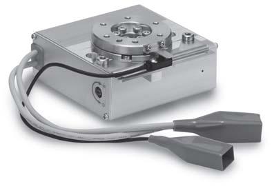
1 Electric Rotary Table Series RoHS Low profile type [mm] Model H Continuous rotation tion Rotation angle: 36 Page 47 H High precision type [mm] Model H H1 49 H3 62 H5 78 H G Shock-less/High speed actuation Max. speed: 42/sec (7.33 rad/sec) Max. acceleration/deceleration: 3/sec 2 (52.36 rad/sec 2 ) Positioning repeatability:.3 (High precision type) Repeatability at the end:.1 (Pushing control/with external stopper) Rotation angle 36, 32 (31), 18, 9 The value indicated in brackets shows the value for the 1. Possible to set speed, acceleration/deceleration, and position. Max. 64 points Energy-saving product Automatic 4% power reduction after the table has stopped. Step data input type Series LECP6 64 points positioning Input using controller setting kit or teaching box Controller/Driver Page 538 CC-Link direct input type Series LECPMJ Not applicable to CE. Size Programless type Series LECP1 14 points positioning Control panel setting Rotating torque [N m] Max. speed [/s] Value when an external stopper is mounted. Pulse input type Series LECPA Page Page 395 -X5 11- LAT3 Motorless LECYU LECSS-T LECS LEC 39


2 Electric Rotary Table and high precision types are available. type/ High precision type/h Rolling bearing High precision bearing The movement in the table s radial thrust direction is reduced. Rotation angle 36, 32 (31 ), 18, 9 The value indicated in brackets shows the value for the 1. Built-in step motor (Servo/24 VDC) Space-saving Output is 3 times with special worm gear. Special worm gear with reduced backlash is used. Maximum rotation torque can be selected. Belt deceleration ratio can be selected. Model [N m] Manual override screw (Both sides) Possible to rotate the table with power OFF by manual override. Easy Mounting of Workpieces Tolerance between table s inside and outside diameter: H8/h8 Dowel pin hole Hollow shaft axis Accommodates wiring and piping of workpieces. Electric gripper Series Hollow shaft axis For alignment of rotation center and workpiece Dowel pin hole Positioning of rotating direction Size Hollow shaft axis ø8 ø17 ø2 391


 G H Continuous Rotation")

 Proximity dog With")


3 Series Easy Mounting of the Main Body Dowel pin hole Mounting Variations Through-hole mounting Reference diameter (boss) Dowel pin hole Body tapped mounting Reference diameter (hole) G H Continuous Rotation Specification Rotation angle: 36 Return to origin with proximity sensor CCW direction ( ) Proximity dog With External Stopper/Rotation Angle: 9 /18 Specification Repeatability at the end:.1 9 specification Adjuster bolt Setting range 18 specification 2 CW direction (+) Proximity sensor 11- -X5 Application Examples Electric gripperper Series Rotation transfer after gripping in combination with a gripper Vertical transfer: No change in speed due to load fluctuation Continuous operation of multiple processes with 36 continuous rotation LAT3 Motorless LECYU LECSS-T LECS LEC 392


4 INDEX Model Selection Page 395 Electric Rotary Table Series How to Order Page 41 Specifi cations Page 42 Construction Page 43 Page 44 Continuous Rotation Specification Electric Rotary Table Series How to Order Page 47 Specifi cations Page 48 Construction Page 49 Page 41 Specifi c Product Precautions Page 413 Controller Step Data Input Type/Series LECP6 Page 551 Controller Setting Kit/LEC-W2 Page 56 Teaching Box/LEC-T1 Page 561 CC-Link Direct Input Type/Series LECPMJ Page 591 Controller Setting Kit/LEC-W2 Page 595 Teaching Box/LEC-T1 Page 596 Gateway Unit/Series LEC-G Page 563 Programless Controller/Series LECP1 Page 567 Step Motor Driver/Series LECPA Page 581 Controller Setting Kit/LEC-W2 Page 588 Teaching Box/LEC-T1 Page


5 Electric Actuators Rotary Table Series Continuous Rotation Specification LAT3 Motorless LECYU LECSS-T LECS LEC 11- -X5 H G 394
 Rotation angle θ: 18 Angular acceleration/ angular deceleration ω : 1 /sec 2 Angular speed ω:")
6 Electric Rotary Table Series Model Selection Series spage 41 Continuous Rotation Specification Series -1sPage 47 Selection Procedure Operating conditions b H a Electric rotary table: 3J Mounting position: Horizontal Load type: Inertial load Ta Configuration of load: 15 mm x 8 mm (Rectangular plate) Rotation angle θ: 18 Angular acceleration/ angular deceleration ω : 1 /sec 2 Angular speed ω: 42 /sec Load mass [m]: 2. kg Distance between shaft and center of gravity H: 4 mm Step1 Moment of inertia Angular acceleration/deceleration q Calculation of moment of inertia w Moment of inertia Check the angular acceleration/deceleration Select the target model based on the moment of inertia and angular acceleration and deceleration with reference to the (Moment of Inertia Angular Acceleration/Deceleration graph). Formula Ι = m x (a 2 + b 2 )/12 + m x H 2 Selection example Ι = 2. x ( )/ x.4 2 =.82 kg m Moment of inertia: [kg m 2 ] K 3J Angular acceleration/deceleration: [/s 2 ] Step2 Necessary torque q Load type Static load: Ts Resistance load: Tf Inertial load: Ta w Check the effective torque Confi rm whether it is possible to control the speed based on the effective torque corresponding with the angular speed with reference to the (Effective Torque Angular Speed graph). Formula Effective torque > Ts Effective torque > Tf x 1.5 Effective torque > Ta x 1.5 Selection example Inertial load: Ta Ta x 1.5 = Ι x ω x 2 π/36 x 1.5 =.82 x 1 x.175 x 1.5 =.21 N m Effective torque: T [N m] K 3J Angular speed: [/s] Step3 Allowable load q Check the allowable load Radial load Thrust load Moment Step4 Rotation time Formula Allowable thrust load > m x 9.8 Allowable moment > m x 9.8 x H Selection example Thrust load 2. x 9.8 = 19.6 N < Allowable load OK Allowable moment 2. x 9.8 x.4 =.784 N m < Allowable moment OK 395 q Calculation of cycle time (rotation time) Speed: [/sec] θ : Rotation angle [ ] ω : Angular speed [ /sec] ω 1 : Angular acceleration [ /sec 2 ] ω 2 : Angular deceleration [ /sec 2 ] 1 2 T1 T2 T3 T4 Time [s] T1: Acceleration time [s] Time until reaching the set speed T2: Constant speed time [s] Time while the actuator is operating at a constant speed T3: Deceleration time [s] Time from constant speed operation to stop T4: Settling time [s] Time until in position is completed Formula Angular acceleration time T1 = ω/ω 1 Angular deceleration time T3 = ω/ω 2 Constant speed time T2 = {θ.5 x ω x (T1 + T3)}/ω Settling time T4 =.2 (sec) Cycle time T = T1 + T2 + T3 + T4 Selection example Angular acceleration time T1 = 42/1 =.42 sec Angular deceleration time T3 = 42/1 =.42 sec Constant speed time T2 = {18.5 x 42 x ( )}/42 =.9 sec Cycle time T = T1 + T2 + T3 + T4 = = 1.49 (sec)
7 Model Selection Series Formulas for Moment of Inertia (Calculation of moment of inertia Ι) Ι: Moment of inertia [kg m 2 ] m: Load mass [kg] 1. Thin bar Position of rotation shaft: Perpendicular to a bar through one end a2 a1 2. Thin bar Position of rotation shaft: Passes through the center of gravity of the bar. 3. Thin rectangular plate (cuboid) Position of rotation shaft: Passes through the center of gravity of a plate. 4. Thin rectangular plate (cuboid) Position of rotation shaft: Perpendicular to the plate and passes through one end. (The same applies to thicker cuboids.) a a1 b a1 a a2 Ι = m1 2 a2 + m2 2 a 3 3 Ι = m 2 a 12 Ι = m 2 12 Ι = m1 + m2 4a1 2 + b a2 2 + b Thin rectangular plate (cuboid) Position of the rotation shaft: Passes through the center of gravity of the plate and perpendicular to the plate. (The same applies to thicker cuboids.) 6. Cylindrical shape (including a thin disk) Position of rotation shaft: Center axis 7. Sphere Position of rotation shaft: Diameter 8. Thin disk (mounted vertically) Position of rotation shaft: Diameter a b r r a r Ι = m 2 + b 2 r 12 Ι = m 2 2r 2 Ι = m 2 r 5 Ι = m 2 4 G H 9. When a load is mounted on the end of the lever a2 r 1. Gear transmission (A) Number of teeth = a (B) a1 m1 m2 Ι = m1 + m2 a2 2 + K 3 (Ex.) Refer to 7 when the shape of m2 is spherical. 2r K = m2 2 5 a1 2 Number of teeth = b 1. Find the moment of inertia ΙB for the rotation of shaft (B). 2. Then, replace the moment of inertia ΙB around the shaft (A) by ΙA, a ΙA = ( ) 2 ΙB b Load Type Load type Static load: Ts Resistance load: Tf Inertial load: Ta Only pressing force is necessary. (e.g. for clamping) Gravity or friction force is applied to rotating direction. Rotate the load with inertia. Ts = F L L Ts : Static load [N m] F : Clamping force [N] L : Distance from the rotation center to the clamping position [m] F Gravity is applied. Friction force is applied. Center of rotation and center of gravity of the load are concentric. L L mg Gravity is applied to rotating direction. Tf = m g L Necessary torque: T = Ts Necessary torque: T = Tf x 1.5 Note 1) Necessary torque: T = Ta x 1.5 Note 1) Resistance load: Gravity or friction force is applied to rotating direction. Ex. 1) Rotation shaft is horizontal (lateral), and the rotation center and the center of gravity of the load are not concentric. Ex. 2) Load moves by sliding on the fl oor. The total of resistance load and inertial load is the necessary torque. T = (Tf + Ta) x 1.5 mg Friction force is applied to rotating direction. Tf = μ m g L Tf : Resistance load [N m] m : Load mass [kg] g : Gravitational acceleration 9.8 [m/s 2 ] L : Distance from the rotation center to the point of application of the gravity or friction force [m] μ : Friction coeffi cient Ta = Ι ω 2 π/36 (Ta = Ι ω.175) Rotation shaft is vertical (up and down). Ta: Inertial load [N m] Ι : Moment of inertia [kg m 2 ] ω : Angular acceleration/deceleration [ /sec 2 ] ω : Angular speed [ /sec] Not resistance load: Neither gravity or friction force is applied to rotating direction. Ex. 1) Rotation shaft is vertical (up and down). Ex. 2) Rotation shaft is horizontal (lateral), and rotation center and the center of gravity of the load are concentric. Necessary torque is inertial load only. T = Ta x 1.5 Note 1) To adjust the speed, margin is necessary for Tf and Ta X5 11- LAT3 Motorless LECYU LECSS-T LECS LEC
8 Series For the LECPA, refer to page 398. For LECP6, LECP1, LECPMJ Moment of Inertia Angular Acceleration/Deceleration 1 Moment of inertia: [kg m 2 ] K 1J Angular acceleration/deceleration: [/s 2 ] Effective Torque Angular Speed 1 Effective torque: T [N m] K 1J Angular speed: [/s] Moment of inertia: [kg m 2 ] K 3J Effective torque: T [N m] K 3J Angular acceleration/deceleration: [/s 2 ] Angular speed: [/s] Moment of inertia: [kg m 2 ].12 5K J Effective torque: T [N m] K 5J Angular acceleration/deceleration: [/s 2 ] Angular speed: [/s] 397
9 Model Selection Series For the LECP6/LECP1/LECPMJ, refer to page 397. For LECPA Moment of Inertia Angular Acceleration/Deceleration 1 Moment of inertia: [kg m 2 ] 3 Moment of inertia: [kg m 2 ] 5 Moment of inertia: [kg m 2 ] K 1J Angular acceleration/deceleration: [/s 2 ] K 3J Angular acceleration/deceleration: [/s 2 ] K 5J Angular acceleration/deceleration: [/s 2 ] Effective Torque Angular Speed 1 Effective torque: T [N m] 3 Effective torque: T [N m] 5 Effective torque: T [N m] K 1J Angular speed: [/s] K 3J Angular speed: [/s] K 5J Angular speed: [/s] G H -X5 11- LAT3 Motorless LECYU LECSS-T LECS LEC 398
10 Series Allowable Load (a) (b) Allowable thrust load [N] Allowable radial load [N] Size (a) (b) Allowable moment [N m] type High precision type type High precision type type High precision type type High precision type Table Displacement (Reference Value) Displacement at point A when a load is applied to point A 1 mm away from the rotation center. 1 A Load Displacement 1 5 Displacement [m] ( type) H1 (High precision type) Displacement [m] ( type) H5 (High precision type) 3 Displacement [m] Load [N] 3 ( type) H3 (High precision type) Load [N] Load [N] 12 Deflection Accuracy: Displacement at 18 Rotation (Guide) Deflection on the top of the table 399 Deflection on the external surface of the table [mm] Measured part ( type) H (High precision type) Defl ection on the top of the table.1.3 Defl ection on the external surface of the table.1.3
11 LAT3 Motorless LECYU LECSS-T LECS LEC 11- -X5 H G 4
12 Electric Rotary Table Series 1, 3, 5 How to Order 1 K S 1 6N 1 q w e r t y u i o! q Table accuracy Nil type H High precision type w Size e Max. rotating torque [N m] r Rotation angle [ ] Symbol Type K J Symbol Nil External stopper: 18 3 External stopper: 9 t Motor cable entry type (entry on the right side) Nil L i Controller/Driver type 1 Nil Without controller/driver 6N LECP6 NPN 6P (Step data input type) PNP 1N LECP1 NPN 1P (Programless type) PNP MJ LECPMJ 2 (CC-Link direct input type) AN LECPA 3 NPN AP (Pulse input type) PNP 1 For details about controller/driver and compatible motor, refer to the compatible controller/driver below. 2 Not applicable to CE. 3 When pulse signals are open collector, order the current limiting resistor (LEC-PA-R-) on page 587 separately. The actuator and controller/driver are sold as a package. Confi rm that the combination of the controller/driver and the actuator is correct. <Check the following before use.> q Check the actuator label for model number. This matches the controller/driver. w Check Parallel I/O confi guration matches (NPN or PNP). Refer to the operation manual for using the products. Please download it via our website, 41 Entry on the left side y Actuator cable type Nil Without cable S Standard cable R Robotic cable (Flexible cable) The standard cable should be used on fi xed parts. For using on moving parts, select the robotic cable. o I/O cable length [m] 1, Communication plug Nil Without cable (Without communication plug connector) S Straight type communication plug connector 3 T T-branch type communication plug connector 3 1 When Without controller/driver is selected for controller/driver types, I/O cable cannot be selected. Refer to page 559 (For LECP6), page 573 (For LECP1) or page 587 (For LECPA) if I/O cable is required. 2 When Pulse input type is selected for controller/driver types, pulse input usable only with differential. Only 1.5 m cables usable with open collector. 3 For the LECPMJ, only Nil, S and T are selectable since I/O cable is not included. Compatible Controller/Driver Type Step data input type CC-Link direct input type u Actuator cable length [m] Nil Without cable A B C 2 Produced upon receipt of order (Robotic cable only) Refer to the specifi cations Note 3) on page 42.! Controller/Driver mounting Nil Screw mounting D DIN rail mounting DIN rail is not included. Order it separately. Caution [CE-compliant products] q EMC compliance was tested by combining the electric actuator series and the controller LEC series. The EMC depends on the confi guration of the customer s control panel and the relationship with other electrical equipment and wiring. Therefore, conformity to the EMC directive cannot be certified for SMC components incorporated into the customer s equipment under actual operating conditions. As a result, it is necessary for the customer to verify conformity to the EMC directive for the machinery and equipment as a whole. w CC-Link direct input type (LECPMJ) is not CE-compliant. [UL-compliant products] When conformity to UL is required, the electric actuator and controller/driver should be used with a UL131 Class 2 power supply. Programless type Pulse input type Series LECP6 LECPMJ LECP1 LECPA Features Compatible motor Value (Step data) input/standard controller CC-Link direct input Capable of setting up operation (step data) without using a PC or teaching box Step motor (Servo/24 VDC) Operation by pulse signals Maximum number of step data 64 points 14 points Power supply voltage 24 VDC Reference page Page 551 Page 591 Page 567 Page 581

13 Electric Rotary Table Series Specifications Note 1) Pushing force accuracy is 1: ±3% (F.S.), 3: ±25% (F.S.), 5: ±2% (F.S.). Note 2) The angular acceleration, angular deceleration and angular speed may fl uctuate due to variations in the moment of inertia. Refer to Moment of Inertia Angular Acceleration/ Deceleration, Effective Torque Angular Speed graphs on pages 397 and 398 for confi rmation. Note 3) The speed and force may change depending on the cable length, load and mounting conditions. Furthermore, if the cable length exceeds 5 m, then it will decrease by up to 1% for each 5 m. (At 15 m: Reduced by up to 2%) Note 4) A reference value for correcting an error in reciprocal operation. Note 5) Impact resistance: No malfunction occurred when the slide table was tested with a drop tester in both an axial direction and a perpendicular direction to the lead screw. (Test was performed with the actuator in the initial state.) Vibration resistance: No malfunction occurred in a test ranging between 45 to 2 Hz. Test was performed in both an axial direction and a perpendicular direction to the lead screw. (Test was performed with the actuator in the initial state.) Note 6) The power consumption (including the controller) is for when the actuator is operating. Note 7) The standby power consumption when operating (including the controller) is for when the actuator is stopped in the set position during operation. Note 8) The maximum instantaneous power consumption (including the controller) is for when the actuator is operating. This value can be used for the selection of the power supply. Table Rotation Angle Range Origin mark (5) Origin mark 5 Note 2) Origin (Stroke end) Stroke end (Origin) Note 3) Dowel 1/31 3, 5/32 Table operating range pin hole Note 1) Model 1K 1J 3K 3J 5K 5J Actuator specifications type External stopper type Electric specifications 2 Rotation angle [ ] Lead [ ] Max. rotating torque [N m] Max. pushing torque [N m] Note 1) 3) Max. moment of LECP6/LECP1/LECPMJ inertia [kg m 2 ] Note 2) 3).4.18 LECPA Angular speed [ /sec] Note 2) 3) 2 to 28 3 to 42 2 to 28 3 to 42 2 to 28 3 to 42 Pushing speed [ /sec] Max. angular acceleration/deceleration [ /sec 2 ] Note 2) 3 Backlash [ ] Positioning repeatability [ ] External stopper: 18 External stopper: 9 Adjuster bolt adjustment range type 18 Adjuster bolt adjustment range 2 2 Adjuster bolt adjustment range 9 Adjuster bolt adjustment range The fi gures show the origin position for each actuator. Note 1) Range within which the table can move when it returns to origin. Make sure a workpiece mounted on the table does not interfere with the workpieces and facilities around the table. Note 2) Position after return to origin. Note 3) [ ] for when the direction of return to origin has changed. ±.3 ±.2 High precision type ±.1 type ±.5 ±.5 High precision type ±.3 type.3 or less Lost motion [ ] Note 4) High.3 or less precision type.2 or less Impact/Vibration resistance [m/s 2 ] Note 5) 15/3 Actuation type Special worm gear + Belt drive Max. operating frequency [c.p.m] 6 Operating temp. range [ C] 5 to 4 Operating humidity range [%RH] 9 or less (No condensation) type Weight [kg] High precision type Rotation angle [ ] -2/ arm (1 pc.) -3/ arm (2 pcs.) Repeatability at the end [ ]/ with external stopper 18 9 ±.1 External stopper setting range [ ] ±2-2/external type Weight arm (1 pc.) High precision type [kg] -3/external type arm (1 pc.) High precision type Motor size Motor type Step motor (Servo/24 VDC) Encoder Incremental A/B phase (8 pulse/rotation) Power supply [V] 24 VDC ±1% Power consumption [W] Note 6) Standby power consumption when operating [W] Note 7) Max. instantaneous power consumption [W] Note 8) G H -X5 11- LAT3 Motorless LECYU LECSS-T LECS LEC
14 Series Construction External stopper type type High precision type Component Parts No. Description Material Note 1 Body Aluminum alloy Anodized 2 Side plate A Aluminum alloy Anodized 3 Side plate B Aluminum alloy Anodized 4 Worm screw Stainless steel Heat treated + Specially treated 5 Worm wheel Stainless steel Heat treated + Specially treated 6 Bearing cover Aluminum alloy Anodized 7 Table Aluminum alloy 8 Joint Stainless steel 9 Bearing holder Aluminum alloy 1 Bearing stopper Aluminum alloy 11 Origin bolt Carbon steel 12 Pulley A Aluminum alloy 13 Pulley B Aluminum alloy 14 Grommet NBR 15 Motor plate Carbon steel 16 type Deep groove ball bearing High Special ball precision type bearing 17 Deep groove ball bearing 18 Deep groove ball bearing 19 Deep groove ball bearing 2 Belt 21 Step motor (Servo/24 VDC) Component Parts No. Description Material Note 22 Table Aluminum alloy Anodized 23 Arm Carbon steel Heat treated + Electroless nickel treated 24 Holder Aluminum alloy Anodized 25 Adjuster bolt Carbon steel Heat treated + Chromate treated 43
15 Electric Rotary Table Series 1 (Rotation angle: 31 ) x M4 x.7 x 6 3H8 ( ) depth H8 ( ) depth Origin mark Manual override screw (Both sides) H [mm] Model H1 H H Manual override screw (Both sides) (Rotation angle: 18 ) 1-3 (Rotation angle: 9 ) Model H1 H2 H H [mm] H2 32 H x Counterbore diameter ø9, depth 5.5 H2 32 H H8 ( ) depth 4 Effective length of accuracy = 7 Effective length of accuracy = (Motor cable entry: Entry on the left side) 2 x M6 x 1. x x M4 x.7 x 6 93 (at max. adjuster bolt length) Note) Not applicable to 18 specification (1-2) H8 ( ) depth 4 Effective length of accuracy = 7 Effective length of accuracy = 2 4 ø42h8 (.39 ) (Motor cable entry: Entry on the left side) ø43h8 (.39) ø42h8 (.39) +.27 ø18h8 ( ) ø8 (through) 2 x ø5.2 (through) 2 x ø ø15h8 ( ) x M5 x.8 (Adjuster bolt) x M6 x 1. x (Motor cable entry: type) 3H8 ( ) depth ø88.5 (Arm operating range) ø43h8 (.39 ) +.27 ø18h8 ( ) ø8 (through) x Counterbore diameter ø9, depth x ø5.2 (through) 2 x ø ø15h8 ( ) (Motor cable entry: type) G H -X5 11- LAT3 Motorless LECYU LECSS-T LECS LEC
16 Series 3 (Rotation angle: 32 ) x M5 x.8 x 8 4H8 ( ) depth H8 ( ) depth x ø6.8 (through) Origin mark Manual override screw (Both sides) Manual override screw (Both sides) H Model H1 H H [mm] (Rotation angle: 18 ) 3-3 (Rotation angle: 9 ) Model H1 H2 H H [mm] H1 H x Counterbore diameter ø11, depth H8 ( ) depth 5 H2 4 H1 Effective length of accuracy = 8 Effective length of accuracy = 2 25 (Motor cable entry: Entry on the left side) 75 ø64h8 (.46) ø63h8 (.46) +.39 ø32h8 ( ) ø17 (through) 2 x ø ø22h8 ( ) x M8 x 1.25 x x M5 x.8 x 8 Note) Not applicable to 18 specification (3-2) H8 ( ) depth (at max. adjuster bolt length) Effective length of accuracy = Effective length of accuracy = (Motor cable entry: Entry on the left side) 2 x M8 x 1.25 x x M6 x 1. (Adjuster bolt) ø64h8 (.46) ø63h8 (.46 ) 25 (Motor cable entry: type) 4H8 ( ) depth ø123.2 (Arm operating range) x Counterbore diameter ø11, depth x ø6.8 (through) +.39 ø32h8 ( ) ø17 (through) 2 x ø ø22h8 ( ) 25 (Motor cable entry: type) 2 2
17 6 x M6 x 1. x H8 ( ) depth Electric Rotary Table Series 5 (Rotation angle: 32 ) 5H8 ( ) depth x ø8.5 (through) Origin mark Manual override screw (Both sides) 26 [mm] Model H1 H H x Counterbore diameter ø14, depth 8.5 H2 H ø76h8 (.46) ø74h8 (.46) ø35h8 ( ) ø2 (through) +.33 ø26h8 ( ) (Motor cable entry: Entry on the left side) 24 (Motor cable entry: type) H8 ( ) depth 5.5 Effective length of accuracy = 11 Effective length of accuracy = 2 2 x ø5 2 2 G H 5-2 (Rotation angle: 18 ) 5-3 (Rotation angle: 9 ) Manual override screw (Both sides) H [mm] Model H1 H2 H H H2 52 H1 158 (at max. adjuster bolt length) 2 x M1 x 1.5 x 2 6 x M6 x 1. x Note) Not applicable to 18 specification (5-2) Effective length of accuracy = 11 Effective length of accuracy = x M8 x 1.25 (Adjuster bolt) ø26h8 ( ) (Motor cable entry: Entry on the left side) 24 (Motor cable entry: type) H8 ( ) depth x M1 x 1.5 x ø76h8 (.46) ø74h8 (.46) 55 5H8 ( ) depth x ø5 19 ø146 (Arm operating range) 3 2 x Counterbore diameter ø14, depth x ø8.5 (through) +.39 ø35h8 ( ) ø2 (through) X5 11- LAT3 Motorless LECYU LECSS-T LECS LEC
18 Continuous Rotation Specification Electric Rotary Table Series 1, 3, 5 How to Order 1 K 1 S 1 6N 1 q w e r t y u i o q Table accuracy Nil type H High precision type r Motor cable entry type (entry on the right side) Nil L Entry on the left side w Size u Controller type 1 Nil Without controller 6N LECP6 NPN 6P (Step data input type) PNP MJ LECPMJ 2 (CC-Link direct input type) 1 For details about controller and compatible motor, refer to the compatible controller below. The LECP1 and LECPA cannot be selected. 2 Not applicable to CE. Rotation angle [ ] 1 36 t Actuator cable type 1 2 Nil Without cable S Standard cable R Robotic cable (Flexible cable) 1 The standard cable should be used on fi xed parts. For using on moving parts, select the robotic cable. 2 Actuator cable is equipped with a lock and sensor. i I/O cable length [m] 1, Communication plug Nil Without cable (Without communication plug connector) S Straight type communication plug connector 2 T T-branch type communication plug connector 2 1 When Without controller is selected for controller types, I/O cable cannot be selected. Refer to page 559 if I/O cable for LECP6 is required. 2 For the LECPMJ, only Nil, S and T are selectable since I/O cable is not included. o Controller mounting Nil Screw mounting D DIN rail mounting DIN rail is not included. Order it separately. e Max. rotating torque [N m] Symbol Type K J y Actuator cable length [m] Nil Without cable A B C 2 Produced upon receipt of order (Robotic cable only) Refer to the specifi cations Note 3) on page 48. Caution [CE-compliant products] q EMC compliance was tested by combining the electric actuator series and the controller LEC series. The EMC depends on the configuration of the customer s control panel and the relationship with other electrical equipment and wiring. Therefore, conformity to the EMC directive cannot be certified for SMC components incorporated into the customer s equipment under actual operating conditions. As a result, it is necessary for the customer to verify conformity to the EMC directive for the machinery and equipment as a whole. w CC-Link direct input type (LECPMJ) is not CEcompliant. [UL-compliant products] When conformity to UL is required, the electric actuator and controller should be used with a UL131 Class 2 power supply. The actuator and controller are sold as a package. Confi rm that the combination of the controller and the actuator is correct. <Check the following before use.> q Check the actuator label for model number. This matches the controller. w Check Parallel I/O confi guration matches (NPN or PNP). q w Refer to the operation manual for using the products. Please download it via our website, 47 Compatible Controller Type Step data input type CC-Link direct input type Series LECP6 LECPMJ Features Value (Step data) input Standard controller CC-Link direct input Compatible motor Step motor (Servo/24 VDC) Maximum number of step data 64 points Power supply voltage 24 VDC Reference page Page 551 Page 591
 ±2 Max. rotating torque [N m].32.22 1.2.8 1 6.6 Max. pushing torque [N m] Note 1) Note 3).16.11.6.4 5 3.3 Max.")
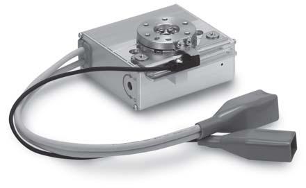
19 Continuous Rotation Specification Electric Rotary Table Series Specifications Table Rotation Angle Range Origin mark Origin Note 2) Model 1K 1J 3K 3J 5K 5J Actuator specifications Electric specifications Rotation angle [ ] 36 Angle setting range [ ] Note 9) ±2 Max. rotating torque [N m] Max. pushing torque [N m] Note 1) Note 3) Max. moment of inertia [kg m 2 ] Note 2) Note 3) Angular speed [ /sec] Note 2) Note 3) 2 to 28 3 to 42 2 to 28 3 to 42 2 to 28 3 to 42 Pushing speed [ /sec] Max. angular acceleration/deceleration [ /sec 2 ] Note 2) 3 Backlash [ ] type ±.2 ±.3 High precision type ±.1 Positioning type ±.5 ±.5 repeatability [ ] High precision type ±.3 Lost motion type.3 or less [ ] Note 4).3 or less High precision type.2 or less Impact/Vibration resistance [m/s 2 ] Note 5) 15/3 Actuation type Special worm gear + Belt drive Max. operating frequency [c.p.m] 6 Operating temperature range [ C] 5 to 4 Operating humidity range [%RH] 9 or less (No condensation) Weight [kg] type High precision type Motor size Motor type Step motor (Servo/24 VDC) Encoder Incremental A/B phase (8 pulse/rotation) Proximity sensor (for return to origin)/input circuit 2-wire Proximity sensor (for return to origin)/input point 1 input Power supply [V] 24 VDC ±1% Power consumption [W] Note 6) Standby power consumption when operating [W] Note 7) Max. instantaneous power consumption Note 8) Note 1) Pushing force accuracy is 1: ±3% (F.S.), 3: ±25% (F.S.), 5: ±2% (F.S.). Note 2) The angular acceleration, angular deceleration and angular speed may fluctuate due to variations in the moment of inertia. Refer to Moment of Inertia Angular Acceleration/ Deceleration, Effective Torque Angular Speed graphs on pages 397 and 398 for confirmation. Note 3) The speed and force may change depending on the cable length, load and mounting conditions. Furthermore, if the cable length exceeds 5 m, then it will decrease by up to 1% for each 5 m. (At 15 m: Reduced by up to 2%) Note 4) A reference value for correcting an error in reciprocal operation. Note 5) Impact resistance: No malfunction occurred when the slide table was tested with a drop tester in both an axial direction and a perpendicular direction to the lead screw. (Test was performed with the actuator in the initial state.) Vibration resistance: No malfunction occurred in a test ranging between 45 to 2 Hz. Test was performed in both an axial direction and a perpendicular direction to the lead screw. (Test was performed with the actuator in the initial state.) Note 6) The power consumption (including the controller) is for when the actuator is operating. Note 7) The standby power consumption when operating (including the controller) is for when the actuator is stopped in the set position during operation. Note 8) The maximum instantaneous power consumption (including the controller) is for when the actuator is operating. This value can be used for the selection of the power supply. Note 9) The angle displayed on the monitor is automatically reset to every 36. To set an angle (position), use the Relative movement mode. If an angle of 36 or more is set using the Absolute movement mode, the correct operation cannot be performed. Note 1) 36 CW direction (+) CCW direction ( ) Note 1) Range within which the table can move. Make sure a workpiece mounted on the table does not interfere with the workpieces and facilities around the table. Note 2) The sensor detection range is recognized as origin. When detecting the sensor, the table rotates in the reverse direction within the sensor detection range. 48 G H -X5 11- LAT3 Motorless LECYU LECSS-T LECS LEC
20 Continuous Rotation Specification Series Construction type High precision type Component Parts No. Description Material Note 1 Body Aluminum alloy Anodized 2 Side plate A Aluminum alloy Anodized 3 Side plate B Aluminum alloy Anodized 4 Worm screw Stainless steel Heat treated + Specially treated 5 Worm wheel Stainless steel Heat treated + Specially treated 6 Bearing cover Aluminum alloy Anodized 7 Table Aluminum alloy 8 Joint Stainless steel 9 Bearing holder Aluminum alloy 1 Bearing stopper Aluminum alloy 11 Pulley A Aluminum alloy 12 Pulley B Aluminum alloy 13 Grommet NBR 14 Motor plate Carbon steel Component Parts (36 type) No. Description Material Note 21 Proximity dog Stainless steel 22 Sensor holder Carbon steel Chromate treated 23 Sensor holder spacer Aluminum alloy 24 Square nut Aluminum alloy 25 Proximity sensor assembly Anodized (High precision type can be used only) 15 type Deep groove ball bearing High precision type Special ball bearing 16 Deep groove ball bearing 17 Deep groove ball bearing 18 Deep groove ball bearing 19 Belt 2 Step motor (Servo/24 VDC) 49
21 Continuous Rotation Specification Electric Rotary Table Series 1 6 x M4 x.7 x 6 2 x Counterbore diameter ø9, depth H8 ( ) depth x ø5.2 (through) Manual override screw (Both sides) H Origin mark H2 32 H1 Effective length of accuracy = 7 Effective length of accuracy = 2 ø43h8 (.39) ø42h8 (.39 ) +.27 ø18h8 ( ) ø8 (through) ø ø15h8 ( ) 2 x ø5 2 G H Model H1 H2 H H [mm] 24 (Motor cable entry: Entry on the left side) 3 (Motor cable entry: type) H8 ( ) depth 4 2 x M6 x 1. x 12 3 (Sensor cable entry: Entry on the left side) (Sensor cable entry: type) LAT3 Motorless LECYU LECSS-T LECS LEC -X
22 Continuous Rotation Specification Series H8 ( ) depth x M5 x.8 x 8 2 x Counterbore diameter ø11, depth x ø6.8 (through) Manual override screw (Both sides) H3 Origin mark H2 4 H1 Effective length of accuracy = 8 Effective length of accuracy = 2 ø64h8 (.46 ) ø63h8 (.46 ) +.33 ø22h8 ( ) +.39 ø32h8 ( ) ø17 (through) ø3 2 x ø5 2 2 Model H1 H2 H H [mm] 25 (Motor cable entry: Entry on the left side) 25 (Motor cable entry: type) H8 ( ) depth 5 2 x M8 x 1.25 x (Sensor cable entry: Entry on the left side) (Sensor cable entry: type)
23 Continuous Rotation Specification Electric Rotary Table Series 5 6 x M6 x 1. x 1 2 x Counterbore diameter ø14, depth H8 ( ) depth x ø8.5 (through) 9 H3 Manual override screw (Both sides) Origin mark.2 1 G H2 H1 H 52 Effective length of accuracy = 11 Effective length of accuracy = 2 ø76h8 (.46 ) ø74h8 (.46 ) ø2 (through) +.39 ø35h8 ( ) ø Model H1 H2 H H [mm] (Motor cable entry: Entry on the left side) ø26h8 ( ) x ø5 24 (Motor cable entry: type) 2 2 -X5 11-5H8 ( ) depth x M1 x 1.5 x 2 25 (Sensor cable entry: Entry on the left side) (Sensor cable entry: type) 15 LAT3 Motorless LECYU LECSS-T LECS LEC 412
24 Series Electric Rotary Table/ Specific Product Precautions 1 Be sure to read this before handling. Refer to page 96 for Safety Instructions. For Electric Actuator Precautions, refer to pages 97 to 912, or Handling Precautions for SMC Products and the Operation Manual on SMC website, Warning Design/Selection 1. If the operating conditions involve load fluctuations, ascending/descending movements, or changes in the frictional resistance, ensure that safety measures are in place to prevent injury to the operator or damage to the equipment. Failure to provide such measures could accelerate the operation speed, which may be hazardous to humans, machinery, and other equipment. 2. Power failure may result in a decrease in the pushing force; ensure that safety measures are in place to prevent injury to the operator or damage to the equipment. When the product is used for clamping, the clamping force could be decreased due to power failure, potentially creating a hazardous situation in which the workpiece is released. Caution 1. If the operating speed is set too fast and the moment of inertia is too large, the product could be damaged. Set appropriate product operating conditions in accordance with the model selection procedure. 2. If more precise repeatability of the rotation angle is required, use the product with an external stopper, with repeatability of ±.1 (18 and 9 with adjustment of ±2 ) or by directly stopping the workpiece using an external object utilizing the pushing operation. 3. When using the electric rotary table with an external stopper, or by directly stopping the load externally, be sure to set to [Pushing operation]. Also, ensure that the workpiece is not impacted externally during the positioning operation or in the range of positioning operation. Warning Mounting 1. Do not drop or hit the electric rotary table to avoid scratching and denting the mounting surfaces. Even slight deformation can cause the deterioration of accuracy and operation failure. 2. When mounting the load, tighten the mounting screws within the specified torque range. Tightening the screws with a higher torque than recommended may cause malfunction, whilst the tightening with a lower torque can cause the displacement of the mounting position. Mounting the workpiece to the electric rotary table The load should be mounted with the torque specifi ed in the following table by screwing the screw into the mounting female thread. If long screws are used, they can interfere with the body and cause a malfunction. Model Screw size Thread length [mm] Max. tightening torque [N m] 1 M4 x M5 x M6 x When mounting the electric rotary table, tighten the mounting screws within the specified torque range. Tightening the screws with a higher torque than recommended may cause malfunction, whilst the tightening with a lower torque can cause the displacement of the mounting position. 413 Mounting Warning Through-hole mounting Body mounting/bottom Model Sensor holder Screw size L Max. tightening torque [N m] 1 M5 x M6 x M8 x Body tapped mounting Model Body mounting/bottom Screw size Max. tightening torque [N m] Body mounting/top 4. The mounting face has holes and slots for positioning. Use them for accurate positioning of the electric rotary table if required. 5. If it is necessary to operate the electric rotary table when it is not energized, use the manual override screws. When it is necessary to operate the product by the manual override screws, check the position of the manual override screws of the product, and leave necessary space. Do not apply excessive torque to the manual override screws. This may lead to damage and malfunction. 6. The 36 type proximity sensor for return to origin can be changed ±3. When changing the position of the proximity sensor for return to origin, tighten the screws with a tightening torque of.6±.1 [N m]. Proximity sensor assembly Max. screw-in depth [mm] 1 M6 x M8 x M1 x L [mm] (Initial setting) Model Cable entry: type/entry on the left side (Between the sensor holder end face and proximity sensor end face) / / /51.5
25 Series Electric Rotary Table/ Specific Product Precautions 2 Be sure to read this before handling. Refer to page 96 for Safety Instructions. For Electric Actuator Precautions, refer to pages 97 to 912, or Handling Precautions for SMC Products and the Operation Manual on SMC website, Caution Handling 1. When an external guide is used, connect it in such a way that no impact or load is applied to it. Use a free moving connector (such as a coupling). 2. The moving force should be the initial value (1%). If the moving force is set below the initial value, there may be variation in the cycle time, or an alarm may be generated. 3. INP output signal 1) Positioning operation When the product comes within the set range by step data [In position], the INP output signal will turn on. Initial value: Set to [.5] or higher. 2) Pushing operation When the effective force exceeds the [Trigger LV] value (including force during operation), the INP output signal will turn on. The [Trigger LV] should be set between 4% and [Pushing force]. a) To ensure that the clamping and external stop is achieved by [Pushing force], it is recommended that the [Trigger LV] be set to the same value as the [Pushing force]. b) When the [Pushing force] and [Trigger LV] are set less than the specified range, the INP output signal will turn on from the pushing start position. 4. When using the electric rotary table with an external stopper, or by directly stopping the load externally, be sure to set to [Pushing operation]. Also, ensure that the workpiece is not impacted externally during the positioning operation or in the range of positioning operation. If the product is used in the positioning operation mode, there may be galling or other problems when the product/workpiece comes into contact with the external stopper or external object. 5. When the table is stopped by the pushing operation mode (stopping/clamping), set the product to a position of at least 1 away from the workpiece. (This position is referred to as the pushing start position.) If the pushing start position (stopping or clamping) is set to the same position as the external stop position, the following alarms may be generated and operation may become unstable. a. Posn failed alarm is generated. It is not possible to reach the pushing start position within the target time. b. Pushing ALM alarm is generated. The product is pushed back from a pushing start position after starting to push. c. Deviation over flow alarm is generated. Displacement exceeding the specifi ed value is generated at the pushing start position. 6.There is no backlash effect when the product is stopped externally by pushing operation. For the return to origin, the origin position is set by the pushing operation. Caution Handling 7. For the specification with an external stopper, an angle adjustment bolt is provided as standard. The rotation angle adjustment range is ±2 from the angle rotation end. If the angle adjustment range is exceeded, the rotation angle may change due to insufficient strength of the external stopper. One revolution of the adjustment bolt is approximately equal to 1 of rotation. 8. In case that gravity is added to the workpiece along the rotation direction when product is mounted vertically, the workpiece may fall down when SVON signal is OFF or EMG is not energizing. 9. When mounting the product, keep a 4 mm or longer diameter for bends in the motor cable. Maintenance Danger 1. The high precision type bearing is assembled by pressing into position. It is not possible to disassemble it. 414 G H -X5 11- LAT3 Motorless LECYU LECSS-T LECS LEC
Electric Rotary Table
 Electric Rotary Table Series RoHS Model H 1 3 5 42 Rotation angle: 36 Page 47 53 68 H 49 G Model H1 H3 H5 High precision type [mm] 62 78 Max. speed: 42 /sec (7.33 rad/sec) Max. acceleration/deceleration:
Electric Rotary Table
 Electric Rotary Table Series LER RoHS H Step Motor (Servo/24 VDC) Low profile New Continuous Basic type [mm] rotation Model H specification LER1 42 LER3 53 LER5 68 High precision type [mm] Model H LERH1
Basic and high precision types are available.
 Series RoHS Model H 1 3 5 42 Rotation angle: 36 Page 47 LEJS LEJB type [mm] Continuous rotation specification LEL Low profile LEFS LEFB 53 68 H 49 LEY LEYG Model H1 H3 H5 LEM High precision type [mm] 62
Electric Rotary Table
 Electric Rotary Table LER Series H Low profile [mm] Model H LER1 42 LER3 53 LER5 68 High precision [mm] Model H LERH1 49 LERH3 62 LERH5 78 Continuous rotation specification RoHS Rotation angle: 36 Pages
240 g. 290 g. Electric Actuators Series LEPY/LEPS. Miniature Rod Type/Miniature Slide Table Type
 Electric Actuators Series / Miniature Rod Type/Miniature Slide Table Type RoHS Compact and lightweight Rod Type Series Weight 24 g 6-25 Maximum pushing force: 5 N Positioning repeatability:.5 mm Possible
240 g. 290 g. Compact and lightweight. Electric Actuators. Series LEPY/LEPS. Miniature Rod Type/Miniature Slide Table Type
 Electric ctuators Series LEPY/LEPS Miniature Rod Type/Miniature Slide Table Type Step Motor (Servo/2 VDC) and lightweight Rod Type Series LEPY Weight 2 g LEPY6-2 RoHS Maximum pushing force: N Positioning
240 g. 290 g. Compact and lightweight. Electric Actuators. LEPY/LEPS Series. Miniature Rod Type/Miniature Slide Table Type
 Electric Actuators LEPY/LEPS Series Miniature Rod Type/Miniature Slide Table Type Compact and lightweight Rod Type LEPY Series Weight 24 g LEPY6-25 3 mm 2.5 mm Slide Table Type LEPS Series Weight 29 g
Electric Actuator/Slider Type Motor Parallel Type
 INFORMATION Electric Actuator/Slider Type Motor Parallel Type RoHS Reduced in overall length Parallel Reduced dimension Reduced in height Reduced dimension Parallel In-line In-line Size Length reduction
Electric Rotary Table
 Electric Rotary Table New RoHS H Low profile Basic type [mm] Model H LER 42 LER LER High precision type [mm] Model H LERH 49 LERH 2 LERH 7 Spacesaving Hollow shaft axis Accommodates wiring and piping of
240 g. 290 g. Electric Actuators. Compact and lightweight. New. Series LEPY/LEPS. Offering 2 types of controller
 Electric Actuators Miniature Rod Type Compact and lightweight Rod Type Series LEPY Miniature Slide Table Type RoHS Maximum pushing force: N Positioning repeatability:. mm Possible to set position, speed
240 g. 290 g. Electric Actuators. Compact and lightweight. New. Series LEPY/LEPS. Offering 2 types of controller
 Electric Actuators Miniature Rod Type Compact and lightweight Rod Type Series LEPY Miniature Slide Table Type New RoHS Maximum pushing force: N Positioning repeatability: ±. mm Possible to set position,
Electric Actuator Series LEL
 Electric Actuator Series LEL Guide Rod Slider RoHS LEFS LEFB Low-profile/Flat Height 48 mm Profile reduced by side mounting of motor DOWN LEL25 48 mm Max. stroke: 1 mm Transfer speed: 1 mm/s LEFB25 115.8
Information. Electric Slide Table/In-line Motor Type. Series LESH D. In-line motor type newly added to electric slide table! Reduced cycle time
 Information Electric Slide Table/In-line Motor Type Series ESHD In-line type newly added to electric slide table! Width dimension shortened by up to % kihabara UDX F, --, Sotokanda, Chiyoda-ku, Tokyo 0-00,
Environment Clean Room Specification
 Environment Clean Room Specification ISO Class 4 *1 (ISO14644-1) Built-in vacuum piping Possible to mount the main body without removing the external cover etc. Body-integrated linear guide specification
Information. Electric Slide Table/In-line Motor Type. Series LESH D. In-line motor type newly added to electric slide table!
 Information kihabara UDX F, --, Sotokanda, Chiyoda-ku, Tokyo 0-00, PN UR http://www.smcworld.com 0 SMC Corporation ll Rights Reserved Electric Slide Table/In-line Motor Type Series ESHD In-line type newly
Information. Model LEYG16 LEYG25 LEYG32
 Information A rod type with guide newly added! Compatible with slide-bearing and ball-bushing bearing. Compatible with moment load and stopper (slide bearing). Speed control/positioning: ax. points Positioning
Electric Actuator/ Guide Rod Type
 ourtesy of M/Flodyne/Hydradyne Motion ontrol Hydraulic Pneumatic Electrical Mechanical (800) 426-5480 www.cmafh.com Size How to Order LEYG M B 50 S N1 Bearing type M Sliding bearing L Ball bushing bearing
LJ1H LEJS40 AC
 Low-profile/Low center of gravity Height dimension reduced by approx. 36% (Reduced by 32 mm) 9 Electric Actuator LEJ Series Slider Type/High Rigidity 58 (Former model) LJ1H2 3 5 1 LJ1H2 LEJS4 RoHS Series
Type. Page 518. A support guide is designed to support workpieces with significant overhang.
 Environment Clean Room Specification ISO Class 4 *1 (ISO14644-1) Built-in vacuum piping Possible to mount the main body without removing the external cover etc. Body-integrated linear guide specification
Problems programming your electric actuator?
 SMC solutions electric actuators Problems programming your electric actuator? Easy setting electric actuators delivering outstanding speed, force and positioning control Electric Actuators Speed, Force
Angular Style Air Gripper
 Angular Style Air Gripper Series /A/M 15 Angular style air gripper Series /A/M - Auto switch is attachable. 8 mm x 0 mm x mm g Body option (Only for A-) Side piping Port Port A- Short body. 1 mm x 0 mm
Series MSU. Rotary Table. High Precision. Vane Type/Sizes 1, 3, 7, 20. High precision series MSUA introduced to vane type rotary tables CAT.
 CAT.ES20-90 C Rotary Table Series MSU Vane Type/Sizes 1, 3, 7, 20 Peripheral table deflection Table top deflection mm or less High Precision mm or less Series MSUB Series MSUA High precision series MSUA
Electric Actuator Controller/Driver
 Slider Series LEF Electric Actuator Controller/Driver Slider /High Rigidity Series LEJ Guide Rod Slider Series LEL P.1 P.2 P.3 Slider / Low Profile Series LEM Rod Series LEY Slide Table Series LES P.4
Precision Cylinder. MTS Series. ø8, ø12, ø16, ø20, ø25, ø32, ø40 MXH MXS MXQ MXQ MXF MXW MXJ MXP MXY MTS D- -X. Series Variations MTS8
 Precision Cylinder Series, ø, ø6, ø, ø, ø, ø MXS Series Variations Model 8 Standard stroke (mm) 7 7 Rod end configuration Cushion Rubber bumper End lock Made to Order Rod Variable stroke/ through-hole
How to Order. Lead wire length Nil L Z M9N L. Type of auto switch for detecting rotation. Nil Without auto switch. Applicable Auto Switch
 Indicator light Indicator light Rotary Gripper Series MRHQ Size:, 1,, 25 How to Order Lead wire length Nil L Z.5 m 3 m 5 m MRH Q D 9 S M9NV L M9N L Q Rotary gripper Gripper Parallel type: 2 fingers D S
Rotary Table/Vane Style
 Rotary Table/Vane Style Series Size: 1, 3, 7, 20 Table top deflection mm or less High Precision Peripheral table deflection mm or less X Series B Series A 147 Rotary Table Values inside ( ) are for Series
Compact Slide. Series MXH ø6, ø10, ø16, ø20
 Compact Slide Series ø, ø, ø, ø The use of an endless track linear guide produces a table cylinder having excellent rigidity, linearity and non-rotating accuracy. Endless track linear guide Series Variations
Series CRB2. Rotary Actuator Vane Style. Size: 10, 15, 20, 30, 40 CRB2 CRBU2 CRB1 MSU CRJ CRA1 CRQ2 MSQ MRQ D- 20- Series Variations.
 Rotary Actuator Vane Style Series :,,,, 4 1 Series Variations Standard Vane type Port location Rotating angle Shaft type Fluid (S) ouble vane () Side ported (Nil) Axial ported (E) 9 18 27 ouble shaft W
Miniature Guide Rod Cylinder ±0.1. Mounting from 2 directions
 Miniature Guide Rod Cylinder Series Non-rotating accuracy : Height ±0.1 Mounting from 2 directions idth Overall length Two auto switches can be mounted even for mm strokes Integral wiring/piping to one
Series MSU. Rotary Table Vane Style. High Precision. Size: 1, 3, 7, 20 CRB2 CRBU2 CRB1 MSU CRJ CRA1 CRQ2 MSQ MRQ D mm or less.
 Rotary Table Vane Style Series Size: 1, 3, 7, 20 Table top deflection mm or less High Precision Peripheral table deflection mm or less Series B Series A 11-5-1 Rotary High precision type Size: 1, 3, 7,
240% 19% reduced. Compact Slide. MXH Series. Improved by up to. With new high rigidity linear guide. 369g. ø6, ø10, ø16, ø g.
 Compact Slide Series ø, ø, ø, ø RoHS Allowable moment MXS Improved by up to MXQ MXQ 2% MXF MXW MXJ MXP MXY With new high rigidity linear guide MTS Allowable moment improvement illustrated below Allowable
Series CRJ. More Compact! Mini-Rotary Actuator Rack-and-Pinion Type/Size: 05, 1
 Mini-Rotary Actuator Rack-and-Pinion Type/: 5, Series CRJ More Compact! CRB CRBU CRJ CRA CRQ MRQ MSQ MSU In our pursuit of excellence in size and weight reduction, we proudly announce the release of the
Rotary Table/Vane Style
 Rotary Table/Vane Style Series MSU Size: 1, 3, 7, 20 Table top deflection mm or less High Precision Peripheral table deflection mm or less CRB2 CRBU2 CRB1 MSU CRJ CRQ2 MSQ MSZ CRQ2X MSQX MRQ Series MSUB
Specifications MHC2-10D MHC2-16D MHC2-20D MHC2-25D MHC2-10S. Double acting MHC2-16S. Single acting MHC2-20S MHC2-25S. Angular style air gripper
 Angular Style Air Gripper Standard Type Series MHC2 Size: 10, 16, 20, 25 A large amount of gripping force is provided through the use of a double piston mechanism, while maintaining a compact design. Built-in
How to Order M9BW. Action. Double acting Single acting. Load voltage Electrical entry direction M9NWV M9NW 12 V 5 V, M9BWV M9BW 12 V 12 V
 Angular Type Air Gripper/Standard Type 2 Series ø, ø1, ø20, ø25 How to Order Angular type air gripper 2 20 Bore size mm 1 1 mm 20 20 mm 25 25 mm D S Action D Double acting Single acting M9BW Made to Order
Information. Electric Actuator/Rod Type. Added size 63 to the LEY series! Series LEY AC Servo Motor (400 W) Size: 63. RoHS
 Size: 63. RoHS") Information SC Corporation Akihabara UDX 1F, 4-14-1, Sotokanda, Chiyoda-ku, Tokyo 1-21, JAPAN http://www.smcworld.com 12 SC Corporation All Rights Reserved Electric Actuator/Rod Type Series EY AC Servo
Information SC Corporation Akihabara UDX 1F, 4-14-1, Sotokanda, Chiyoda-ku, Tokyo 1-21, JAPAN http://www.smcworld.com 12 SC Corporation All Rights Reserved Electric Actuator/Rod Type Series EY AC Servo
Type. Rod type. Auto switch mountable. Guide rod type. Size: 25, 32, 63 Note) Size: 25, 32. Rod type/ In-line motor type. Driver.
 Size: 25, 32. Rod type/ In-line motor type. Driver.") Electric ctuators Rod Type Guide Rod Type New RoHS Step Motor (Servo/ VDC) Rod Type Series Long stroke: Max. 00 mm (, ) Servo Motor ( VDC) Mounting variations Direct mounting: directions, racket mounting:
Electric ctuators Rod Type Guide Rod Type New RoHS Step Motor (Servo/ VDC) Rod Type Series Long stroke: Max. 00 mm (, ) Servo Motor ( VDC) Mounting variations Direct mounting: directions, racket mounting:
Electric Actuator. New. New. Long stroke: Max. 500 mm (LEY32)
") Electric ctuator Rod Type Guide Rod Type New Step otor (Servo/ VDC) Servo otor ( VDC) Type Rod Type Series LEY :,, Long stroke: ax. 00 mm (LEY) ounting variations Direct mounting: directions, Bracket mounting:
Electric ctuator Rod Type Guide Rod Type New Step otor (Servo/ VDC) Servo otor ( VDC) Type Rod Type Series LEY :,, Long stroke: ax. 00 mm (LEY) ounting variations Direct mounting: directions, Bracket mounting:
10 million cycles. Improved durability. Shock Absorber/Soft type. RJ Series. Maximum operating cycles M6, M8, M10, M14, M20, M27
 Shock Absorber/Soft type Series M, M, M, M, M, M Improved durability RoS Long-term continuous operation has been realized by employing the pre-load mechanism, newly-developed oil seals. Maximum operating
: 660 N. For material handling and clamping of small workpieces. CKZT25 -X2797 (Base Type) Power Clamp Cylinder INFORMATION. ø
 Power Clamp Cylinder INFORMATION. ø") For material handling and clamping of small workpieces INFORMATION Power Clamp Cylinder ø25 Compact Type 34 mm Lightweight Compact High clamping force Lock function 53 mm Lightweight Weight : 580 g Compact
For material handling and clamping of small workpieces INFORMATION Power Clamp Cylinder ø25 Compact Type 34 mm Lightweight Compact High clamping force Lock function 53 mm Lightweight Weight : 580 g Compact
Electric Slide Table
 Doc. no. LES-OM00213 PRODUCT NAME Electric Slide Table MODEL / Series / Product Number LES Series Applicable models: LES[]R,LES[]L,LES[]D,LESH[]R,LESH[]L,LESH[]D R Type Standard /LES[]R Series L Type Standard
Low Profile Air Gripper
 Low Profile Air Gripper Series MHF2 MHZ MHF MHL MHR MHK MHS MHC MHT MHY MHW -X Low profile air gripper with space-saving design MRHQ MA D- Courtesy of Steven ngineering, Inc.-2 Ryan Way, South San Francisco,
Electric Actuator / Rod Type
 Doc. no. LEY-OM00206 PRODUCT NAME Electric Actuator / Rod Type MODEL / Series LEY Series Applicable models: LEY[], LEYG[], LEY Series (Rod type) LEYG Series (Guide Rod type) LEC Series Contents
Electric Actuator. New. Low-profile/Low center of gravity. Series LEJ CAT.ES A. Slider Type. High Rigidity. Ball Screw Drive Series LEJS
 Electric Actuator High Rigidity Slider Type New RoHS Low-profile/Low center of gravity Height dimension reduced by approx. 31% (Reduced by 28 mm) LJ1H2 Series New LEJS4 (Existing model) LJ1H2 Work load
Rotary Actuated Air Gripper
 Rotary ctuated ir Gripper MHR, MDHR/MHR3, MDHR3 -finger type: Size, 15,, 3/ 3-finger type: Size, 15 High Precision - Repeatability ±.1 mm Parallel opening and closing mechanism utilizing a cross roller
ROBO Cylinder Rotary Straight Motor Model 64mm Width 200V Servo Motor I N T P O. Notes on Selection. Deceleration Rated torque
 Slider RCS2 Cylinder RCS2-RT6 SA4D : Aluminum base SS4D : Steel base Cylinder Rotary Straight Model mm Width 200V Configuration: RCS2 RT6 I 60 18 L Series Encoder Deceleration Ratio Compatible Cable Length
Mini Free Mount Cylinder
 Mini Free Mount Cylinder Series ø, ø, ø, ø, ø, ø1, ø Series 1 ction Stroke 1 2 0 0 0 Clean uto switch series None Rod end Male threaded Without thread Solid state switch D-F D-M9 D-M9 W Female threaded
180 Angular Style Air Gripper
 8 Angular Style Air Gripper Series 2/2 Cam Style / Rack & Pinion Style 99 8 Angular Style Air Gripper Cam Style Rack & Pinion Style Series 2/2 Series 2/Cam Style Light and compact size in small bore sizes
Hollow Rotary RCP6-RTFML.
 Hollow Rotary RCP6-RTFML www.intelligentactuator.com Slim and lightweight RCP6-RTFML Rotary with large-diameter hollow shaft of φ49, suitable for combined axes, is now available 1 f49 large-diameter hollow
Wedge Cam Operation Slide Guide. Air Gripper/2-Finger Type ø12, ø16, ø20, ø25. Option: Stainless steel
 Wedge Cam Operation Slide Guide Air Gripper/2-inger Type ø2, ø, ø, ø2 MH MH oad Resistant, Dust Cover for Adverse Environments 2 types of finger materials types of dust cover materials Standard: Carbon
Low Profile Air Gripper. Series MHF2. Low profile air gripper with space-saving design is newly released. 5-77
 Low Profile Air Gripper Low profile air gripper with space-saving design is newly released. 5-77 Low Profile Air Gripper Height is approximately / the size of an equivalent Series MHZ2. MHZ2-D 42 Bore
Guide Table. MGF Series
 Guide Table MGF Series ø, ø, ø0 Low-profile compact cylinder utilizes a large concentric guiding sleeve to provide excellent eccentric load resistance. Mounting height greatly reduced Low-profile cylinder
Guide Table. ø40, ø63, ø100
 Guide Table Series MGF ø, ø, ø Low-profile compact cylinder utilizes a large concentric guiding sleeve to provide excellent eccentric load resistance. Mounting height greatly reduced Low-profile cylinder
Rotary Actuator. New. New RoHS. Vane Type 10, 15, 20, 30, 40. Many combinations available! Series CRB2. Two shaft options available
 Rotary Actuator Vane Type,,,, Many combinations available! New RoHS Two shaft options available With auto switch unit New Port locations modified Change in angle: Parallel piping ( ), Conventional type
Suitable for conveyor lines without an air supply
 Contact our sales office regarding a delivery date or a price since this is a special model. P107X-011E P: OW P.G.Information (pecialized product) Electric topper Cylinder LEBQ eries MC CORPORATION 4-14-1,
Low Profile Air Gripper
 Low Profile Air Gripper MHF2 Series ø8, ø, ø, ø RoHS Low profile air gripper with space-saving design MHZ MHF MHL MHR MHK MHS MHC MHT MHY MHW -X MRHQ MA D- 465 Low Profile Air Gripper MHF2 Series Height
10, 15, 20, 30, 40 MSQX
 Possible to transfer a workpiece at low-speed. Rotation time adjustment range: 1 to 5 ( s/90 ) Lowspeed Standard Low-Speed Rotary ctuator / Series :,,,, :,,, Model,,,,,,,,,,,,,, Rotation time adjustment
MHR3/MDHR3 Series. Rotary Actuated Air Gripper/3-Finger Type. Size: 10, 15 MDHR 3 10 R M9N S. How to Order. Without auto switch
 Rotary ctuated ir Gripper/3-Finger Type MHR3/MDHR3 Series Size:, 1 How to Order Without auto switch MHR 3 R Connecting port R ody side R: ody side Port With auto switch (uilt-in magnet) MDHR 3 R M9N S
Hybrid Control System, Alpha Step
 B Hybrid Control System, Alpha Step Hybrid Control System B-1 Overview... B-2 Overview Hybrid Control System Battery-Free, Absolute Sensor Equipped AZ Series... B-16 Electric Linear Slides EZS Series AZ
Stepper Motors ver ver.5
 A Stepper s Stepper s A-1 Overview... A-2 Overview and... A-15 & Stepper and RK Series A-16 RK... A-47... A-51 Stepper Series A-52 Stepper Series A-8 See Full Product Details Online www.orientalmotor.com
Series CRQ2. Compact Rotary Actuator Rack & Pinion Style. Size: 10, 15, 20, 30, 40. Rotary actuator body serves as a flange.
 Compact Rotary ctuator Rack & Pinion Style Series CRQ2 :,,,, Unidirectional pipe connection possible uilt-in cushion, : Rubber bumper,, : ir cushion Equipped with an angle adjusting mechanism Double piston
Linear Alignment. motion. 2 Flexible combination of XY. 4 High resolution and high responsiveness. accuracy. Optical linear encoder scale head
 SADE SADE/X SADE/S 2 2 Alignment Stage SA Linear motor drive SA DE Crossed roller bearing -table Linear Alignment Points 1Compact XY-table motion. Using a Linear Way L miniature linear motion rolling guide
Electric Actuator. New. New. Long stroke:
 Electric ctuator Rod Type Step otor (Servo/2 VDC) Long stroke: Guide Rod Type Rod Type Series LEY ax. 00 mm (LEY) ounting variations Direct mounting: directions, Bracket mounting: types uto switch can
Electric Actuators. New. Motorless Type. Series LE. Your motor and driver can be used together! Manufacturers of compatible motors: 8 companies
 Motorless Type Electric Actuators New RoHS Your motor and driver can be used together! Manufacturers of compatible motors: companies Mitsubishi Electric Corporation SANYO DENKI CO., LTD. Panasonic Corporation
NEW LM Actuator. US Only. Optimal for high speed and long stroke Long term maintenance-free operation is actualized Lightweight, compact structure
 NEW LM Actuator Optimal for high speed and long stroke Long term maintenance-free operation is actualized Lightweight, compact structure TY US Only CATALOG No.352E Structure of Model TY This belt drive
Parallel Style Air Gripper: Wide Type
 Parallel Style Air Gripper: Wide Type Series MHL Built-in dust-protection mechanism A scraper with a dust lip is adopted for all rod rotating parts. A large amount of gripping force is provided through
Stopping Accuracy of Brushless
 Stopping Accuracy of Brushless Features of the High Rigidity Type DGII Series Hollow Rotary Actuator The DGII Series hollow rotary actuator was developed for positioning applications such as rotating a
Type. Page 518. A support guide is designed to support workpieces with significant overhang.
 Environment Clean Room Specification ISO Class 4 *1 (ISO14644-1) Built-in vacuum piping Possible to mount the main body without removing the external cover etc. Body-integrated linear guide specification
Low-Speed Rotary Actuator
 Low-Speed Rotary Actuator Series CRQX/ Possible to transfer a workpiece at low-speed. Rotation time adjustment range: to ( s/9 ) Lowspeed Standard Model CRQX CRQ,,,,,,,,,,,,,, Rotation time adjustment
Parallel Style Air Gripper
 Parallel tyle Air Gripper eries MHZ MHZ MH -X D- Courtesy of teven Engineering, Inc.-3 Ryan Way, outh an Francisco, CA 98-37-Main Office: () 88-9-Outside Local Area: (8) 8-9-www.stevenengineering.com 373
For material handling and clamping of small workpieces
 For material handling and clamping of small workpieces Power Clamp Cylinder New ø25, ø32 Compact Type INFORMATION 34 mm Lightweight Compact High clamping force Lock function 53 mm Lightweight Weight :
Your motor and driver can be used together! Manufacturers of compatible motors: 8 companies. Ball screw drive. Series LEJS. Size
 Motorless Type Electric Actuators New RoHS Your motor and driver can be used together! Manufacturers of compatible motors: companies Mitsubishi Electric Corporation SANYO DENKI CO., LTD. Panasonic Corporation
Guide Table. Series MGF
 Guide Table Series MGF ø, ø, ø0 Low-profile compact cylinder utilizes a large concentric guiding sleeve to provide excellent eccentric load resistance. Mounting height greatly reduced Low-profile cylinder
Solenoid Gripper GRS.
 Solenoid Gripper GRS www.intelligentactuator.com Small, affordable, easy to operate! The new Solenoid Gripper 1 Small size Compact and lightweight electric gripper that fits in the palm of the hand. 2
Rotary Actuator. New RoHS. New. Vane Type 10, 15, 20, 30, 40. Many combinations available! Series CRB 2. Standard type/series CRB2
 Rotary Actuator Vane Type 1, 15, 2, 3, 4 Standard Type Free Mount Type Many combinations available! Standard type/series Piping ports are located on the flat surface. Fittings can be secured firmly, piping
Electric Actuator /Slider Type
 Doc. no. LEF-OM00201 PRODUCT NAME Electric Actuator /Slider Type MODEL / Series LEF Series LEC Series Contents Safety Instructions... 2 1. Procedure before operation/simple setting to use
Series MHK2. Wedge Cam Operation Slide Guide Air Gripper (2 Finger)
") Wedge Cam Operation lide Guide Air Gripper (2 inger) ø2, ø, ø2, ø2 oad Resistant, Dust Cover for Adverse Environments 2 types of finger materials types of dust cover materials tandard: Carbon steel Optional:
Wedge Cam Operation lide Guide Air Gripper (2 inger) ø2, ø, ø2, ø2 oad Resistant, Dust Cover for Adverse Environments 2 types of finger materials types of dust cover materials tandard: Carbon steel Optional:
for PowerCON SCARA MSEL-PCX/PGX Program Controllers PowerCON SCARAIXP Series Arm Length 180mm/250mm 550mm/650mm
 PowerCON SCARAIXP Series Program Controllers for PowerCON SCARA MSEL-PCX/PGX Series added Arm Length 18mm/25mm 55mm/65mm www.intelligentactuator.com Introducing Arm Lengths 18/25/55/65 Added in Cost-effective
Toggle Type Air Gripper
 ø2, ø40, ø50, ø6 Ideal for gripping heavy workpiece Toggle mechanism is adopted. Holds workpiece even when pressure drops. The toggle mechanism that activates when the finger closes realizes strong and
2-Color Display High-Precision Digital Pressure Switch
 2-Color Display High-Precision Digital Pressure Switch Settings can be copied to up to 1 slave sensors at once. The settings of the master sensor can be copied to the slave sensors. Reduced setting efforts
Free Mount Cylinder. Series. Series CU CAT.EUS20-95 B -UK. Space-saving. Auto Switch Capable P. 4, 23, 37 P. 45 P. 43
 CAT.EUS- B -UK Free Mount Cylinder A space-saving air cylinder with multiple surfaces capable of direct mounting. Offered in many variations. Space-saving The multiple surface direct mounted rectangular
Series 10-ZSE40A(F)/10-ISE40A
/10-ISE40A") Series 10-ZSEA(F)/10-ISEA RoHS 2-Color Display High Precision Digital Pressure Switch How to Order For positive pressure Clean series For vacuum/ compound pressure 01 N01 W1 10 Rated pressure range ISEA
Series 10-ZSEA(F)/10-ISEA RoHS 2-Color Display High Precision Digital Pressure Switch How to Order For positive pressure Clean series For vacuum/ compound pressure 01 N01 W1 10 Rated pressure range ISEA
Slide Unit. CX2/CXWM/CXWL Series. Slide Bearing/CX2:ø10, ø15, ø25 CXWM:ø10, ø16, ø20, ø25, ø32 Ball Bushing Bearing/CXWL:ø10, ø16, ø20, ø25, ø32
 Slide Unit CX/M/L Series Slide Bearing/CX:ø0, ø, ø5 M:ø0, ø, ø0, ø5, ø3 Ball Bushing Bearing/L:ø0, ø, ø0, ø5, ø3 Provided with shock absorbers to absorb impact and noise. The slide unit can absorb energy
Vane Type Rotary Actuator
 Vane Type Rotary Actuator 5, 63, 8, 1 New Compact auto switches are mountable! (D-M9 ) Compact auto switch D-M9 Stainless steel specification for main parts : 5, 63, 8, 1 Special screw Hexagon socket head
5-Phase Stepper Motor
 Ordering Information Application model: Standard shaft type, Hollow shaft type, Shaft type+ A 8K M 5 6 6 B Motor type Motor phase Rated current Max. Holding torque Shaft type Motor length : provides single
Low-Speed Rotary Actuator
 Low-Speed Rotary Actuator Series CRQX/ Possible to transfer a workpiece at low-speed. Rotation time adjustment range: to ( s/9 ) Lowspeed Standard Model CRQX CRQ,,,,,,,,,,,,,, Rotation time adjustment
High-Efficiency AR Series. RK Series /0.72 /Geared. CRK Series. RBK Series. CMK Series. 2-Phase Stepping Motors A-278.
 A Stepping Motors Stepping Motors Introduction A-2 Introduction AC Power Supply Input Stepping Motor and Driver Packages A-17 DC Power Supply Input Stepping Motor and Driver Packages Stepping Motors (Motor
CAT.ES20-53 E. Dual-Rod Cylinder. Series CXS. CXS Dual-Rod Cylinder with Air Cushion Compact Type Series CXSJ. New:
 CAT.ES-3 E Dual-Rod Cylinder Series New: Dual-Rod Cylinder with Air Cushion Compact Type Series J Dual-Rod Cylinder with guide function for pick-and-place applications Series! Twice the thrust Non-rotating
MULTI SLIDERS CONTENTS
 CAD drawing data catalog is available. ACTUATORS GENERAL CATALOG CONTENTS Features 923 Handling Instructions and Precautions 925 Specifications 929 Order Codes 930 Inner Construction 931 Dimensions 932
Space-saving installation Flexible motor mounting
 Space-saving installation Flexible motor mounting compatible!! Pulse train input compatible Automatic actuator recognition Addition of new controller compatible with pulse trains Enables current position
Air Gripper (2 Finger) (3 Finger)
 (3 Finger)") Rotary Actuated Air Gripper ( Finger) (3 Finger) MHR/MDHR, MHR3/MDHR3 High Precision - Repeatability ±0.01mm Parallel opening and closing mechanism utilizing a cross roller guide produces smooth operation
Rotary Actuated Air Gripper ( Finger) (3 Finger) MHR/MDHR, MHR3/MDHR3 High Precision - Repeatability ±0.01mm Parallel opening and closing mechanism utilizing a cross roller guide produces smooth operation
New Product. High speed transfer 0.5 sec./cycle realized. Linear type P&P unit. PPLX Series PPLX SERIES CC-N-371A 4
 High speed transfer 0.5 sec./cycle realized New Product Linear type P&P unit PPLX Series PPLX SERIES CC-N-371A 4 Lb stroke length (vertical) Reliable and high speed transfer 0.5 second/cycle Available
Free Mount Cylinder. Series CU. A space-saving air cylinder with multiple surfaces capable of mounting directly. Offered in rich variations.
 Free Mount Cylinder Series CU A space-saving air cylinder with multiple surfaces capable of mounting directly. Offered in rich variations. Space-saving The multiple surface direct mounting with a square
IXP Series MSEL-PGX. tuator.d e. PowerCon SCARA Robot. PowerCon SCARA Program Controller. Arm Length 180mm/250mm 550mm/650mm
 GB PowerCon SCARA Robot PowerCon SCARA Program Controller IXP Series MSEL-PGX Series added Arm Length 18mm/25mm 55mm/65mm www.intelligentac tuator.d e Introducing Arm Lengths 18/25/55/65 Added in Cost-effective
Series MHZ2/MHZJ2. Parallel Type Air Gripper. Series MHZJ2 with dust cover introduced! New finger options added to Series MHZ2 standard type.
 CAT.E273- B Parallel Type Air Gripper Standard Type With Dust Cover Series MHZ2/MHZJ2 Series MHZJ2 with dust cover introduced! New finger options added to Series MHZ2 standard type. Integrated linear guide
Compact Cylinder/Plate type
 Compact Cylinder/Plate type Series :,,, Width: Reduced by up to % (compared with SMC series) Total length: Reduced by up to % Volume: Reduced by up to 1% Weight: Reduced by up to % (compared with SMC series
Series ITV0000. Compact Electro-Pneumatic Regulator ITV N Q. IITV00 02 n. How to Order. For single unit and single unit for manifold
 Compact Electro-Pneumatic Regulator Series ITV How to Order For single unit and single unit for manifold ITV N Q Pressure range. MPa MPa.9 MPa Power supply voltage 4 VDC ±% to VDC Cable connector N S L
Electric Cylinder. LZB/LZC Series. It can be operated like an air cylinder. LZB Series. LZC Series LEF LEJ LEL LEM LEY LES LER LEH 25A- LEC
 Electric Cylinder LZB/LZC Series It can be operated like an air cylinder. LZB Series LZC Series Model LZB LZC Max. thrust Max. speed 196 N 0 mm/s Lead screw Slide screw: ø8, ø Lead: 2, 6, Stroke 25, 40,
! Contact our sales office regarding a delivery date or a price since this is a special model. Auto switch D-M9 series mountable
 ! Contact our sales office regarding a delivery date or a price since this is a special model. P.G.Information (Specialized Product) Electric Stopper Cylinder/LEBH-X3 Series SP147X-019E-1 RP:SX SMC Corporation
2-Color Display High-Precision Digital Pressure Switch
 2-Color Display High-Precision Digital Pressure Switch Series ZSE3/ISE3 2-color digital display allows you to choose the setting according to your application requirements. 4 different display settings