240 g. 290 g. Electric Actuators Series LEPY/LEPS. Miniature Rod Type/Miniature Slide Table Type
|
|
|
- Dustin Wilkerson
- 6 years ago
- Views:
Transcription


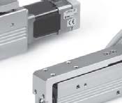
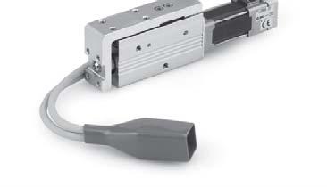
1 Electric Actuators Series / Miniature Rod Type/Miniature Slide Table Type RoHS Compact and lightweight Rod Type Series Weight 24 g 6-25 Maximum pushing force: 5 N Positioning repeatability:.5 mm Possible to set position, speed and force. (64 points) Size: 6, 1 Page mm mm 2.5 mm Slide Table Type Series Weight 29 g 6-25 Size: 6, 1 Page X5 LEH Linear guide integrated 41 mm 21 mm Step data input type Series LECP6 64 points positioning Input using controller setting kit or teaching box Controller/Driver CC-Link direct input type Series LECPMJ Not applicable to CE mm Programless type Series LECP1 14 points positioning Control panel setting Page 538 Pulse input type Series LECPA LAT3 Motorless 36
 Series")


![Screw lead Pushing force [N] Basic Compact Max.](/docs-images/76/73291549/images/2-7.jpg "work load [kg] (Horizontal) Max.")
![work load [kg] (Vertical) Basic Compact Basic](/docs-images/76/73291549/images/2-8.jpg "Compact Basic Max.")
![speed [mm/s] (Horizontal) Compact Stroke [mm]](/docs-images/76/73291549/images/2-10.jpg "Page Rod type Series 6 1 4 8 5 1 14 to 2 7 to 1")

2 Electric Actuators Rod Type Miniature Rod Type Compact and lightweight Weight 24 g (6-25) Series Miniature Slide Table Type Slide Table Type Motor type can be selected to suit the application. (Size 1 only) High pushing force type/basic type Compact and lightweight motor type Weight Series 29 g (6-25) Linear guide Body mounting through-hole Manual override screw For rod/table operation. Adjustment operation possible when power OFF Body mounting through-hole Can be mounted close together. Application Examples Pick and place Delivery Alignment Press fitting Variations Type Size Screw lead Pushing force [N] Basic Compact Max. work load [kg] (Horizontal) Max. work load [kg] (Vertical) Basic Compact Basic Compact Basic Max. speed [mm/s] (Horizontal) Compact Stroke [mm] Page Rod type Series to 2 7 to 1 25 to to to 4 12 to Page Slide table type Series to 2 7 to 1 25 to to to 4 12 to Page 374


 For")


 11- Bottom entry")
 Entry on the")
 LAT3")
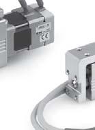
3 Series / Mounting Variations Mounting from various directions Side mounting (Body mounting through-hole) Side mounting (Body tapped) For slide table type, mounting from both sides is possible. For slide table type, body tapped from both sides. Bottom mounting (Body tapped) Axial mounting Rod type only (Body tapped) -X5 LEH Motor Cable Entry Direction Can be selected from 4 directions. Top entry (Basic model) Entry on the right side (When selecting R ) 11- Bottom entry (When selecting U ) Entry on the left side (When selecting L ) LAT3 Motorless 362


4 INDEX Electric Actuator/Miniature Rod Type Series Model Selection Page 365 How to Order Page 369 Specifi cations Page 371 Construction Page 371 Dimensions Page 372 Electric Actuator/Miniature Slide Table Type Series Model Selection Page 374 How to Order Page 381 Specifi cations Page 383 Construction Page 383 Dimensions Page 384 Specifi c Product Precautions Page 386 Controller Step Data Input Type/Series LECP6 Page 551 Controller Setting Kit/LEC-W2 Page 56 Teaching Box/LEC-T1 Page 561 CC-Link Direct Input Type/Series LECPMJ Page 591 Controller Setting Kit/LEC-W2 Page 595 Teaching Box/LEC-T1 Page 596 Gateway Unit/Series LEC-G Page 563 Programless Controller/Series LECP1 Page 567 Step Motor Driver/Series LECPA Page 581 Controller Setting Kit/LEC-W2 Page 588 Teaching Box/LEC-T1 Page


5 Electric Actuators Miniature Rod Type Series Miniature Slide Table Type Series LAT3 Motorless 11- LEH -X5 364
 Step 2 Check the cycle time. Selection Example Operating conditions Workpiece mass:.")
![2 [kg] Speed: 2 [mm/s] Acceleration/Deceleration: 3 [mm/s 2 ] Stroke: 4 [mm] Workpiece mounting condition: Vertical upward downward transfer W.6.5.4.3.2 Lead 4 (6K) Lead 8 (6J) Step 1 Check the work load speed.](/docs-images/76/73291549/images/6-1.jpg "<Speed Work load graph> Select the target model based on the workpiece mass and speed with reference to the <Speed Work load graph>.")
6 Electric Actuator/Miniature Rod Type Series Model Selection Series spage 369 Selection Procedure Positioning Control Selection Procedure Step 1 Check the work load speed. (Vertical transfer) Step 2 Check the cycle time. Selection Example Operating conditions Workpiece mass:.2 [kg] Speed: 2 [mm/s] Acceleration/Deceleration: 3 [mm/s 2 ] Stroke: 4 [mm] Workpiece mounting condition: Vertical upward downward transfer W Lead 4 (6K) Lead 8 (6J) Step 1 Check the work load speed. <Speed Work load graph> Select the target model based on the workpiece mass and speed with reference to the <Speed Work load graph>. Selection example) The 6J is temporarily selected based on the graph shown on the right side. It is necessary to mount a guide outside the actuator when used for horizontal transfer. When selecting the target model, refer to page 371 for the horizontal work load in the specifi cations, and page 386 for the precautions Speed [mm/s] <Speed Work load graph> (6/Step motor) 4 Step 2 Check the cycle time. Calculate the cycle time using the following calculation method. Cycle time T can be found from the following equation. T = T1 + T2 + T3 + T4 [s] T1: Acceleration time and T3: Deceleration time can be obtained by the following equation. T1 = V/a1 [s] T2: Constant speed time can be found from the following equation. T4: Settling time varies depending on the conditions such as motor types, load and in position of the step data. Therefore, calculate the settling time with reference to the following value. T4 =.2 [s] T3 = V/a2 [s] L.5 V (T1 + T3) T2 = [s] V Calculation example) T1 to T4 can be calculated as follows. Speed: V [mm/s] a1 T1 L a2 T2 T3 T4 L : Stroke [mm] (Operating condition) V : Speed [mm/s] (Operating condition) a1: Acceleration [mm/s 2 ] (Operating condition) a2: Deceleration [mm/s 2 ] (Operating condition) Reaches the target position Time [s] T1: Acceleration time [s] Time until reaching the set speed T2: Constant speed time [s] Time while the actuator is operating at a constant speed T3: Deceleration time [s] Time from the beginning of the constant speed operation to stop T4: Settling time [s] Time until positioning is completed T1 = V/a1 = 2/3 =.67 [s], T3 = V/a2 = 2/3 =.67 [s] L.5 V (T1 + T3) ( ) T2 = = =.133 [s] V 2 T4 =.2 [s] Therefore, the cycle time can be obtained as follows. T = T1 + T2 + T3 + T4 = =.467 [s] Based on the above calculation result, the 6J-5 is selected. 365
7 Model Selection Series Selection Procedure Pushing Control Selection Procedure Step 1 Check the duty ratio. The duty ratio is a ratio at the time that can keep being pushed. Selection Example Operating conditions Step 2 Check the pushing force. Step 3 Mounting condition: Horizontal (pushing) Duty ratio: 7 [%] Jig weight:.5 [kg] Speed: 15 [mm/s] Pushing force: 3 [N] Stroke: 4 [mm] Check the lateral load on the rod end. Step 1 Check the duty ratio. <Conversion table of pushing force duty ratio> Select the [Pushing force] from the duty ratio with reference to the <Conversion table of pushing force duty ratio>. Selection example) Based on the table below, Duty ratio: 7 [%] Therefore, the set value of pushing force will be 8 [%]. <Conversion table of pushing force duty ratio> (1L) Set value of pushing force [%] Duty ratio [%] Continuous pushing time [minute] 7 or less [Set value of pushing force] is one of the step data input to the controller. [Continuous pushing time] is the time that the actuator can continuously keep pushing. Step 2 Check the pushing force. <Set value of pushing force Force graph> Select the target model based on the set value of pushing force and force with reference to the <Set value of pushing force Force graph>. Selection example) Based on the graph shown on the right side, Set value of pushing force: 75 [%] Pushing force: 3 [N] Therefore, the 1LK is temporarily selected. Step 3 Check the lateral load on the rod end. <Allowable lateral load on the rod end> Confi rm the allowable lateral load on the rod end of the actuator: 1L, which has been selected temporarily with reference to the <Allowable lateral load on the rod end>. Selection example) Based on the table below, Jig weight:.5 [kg].5 [N] Therefore, the lateral load on the rod end is in the allowable range. <Allowable lateral load on the rod end> Model Allowable lateral load on the rod end [N] 6 (Basic).5 1 (Basic) 1. 1L (Compact) 1. Based on the above calculation result, the 1LK-5 is selected. Position Force [N] Pushing control B A Duty ratio = A/B x 1 [%] Lead 5 (1LK) Time Lead 1 (1LJ) 6% 7% 75% 8% 9% 1% Set value of pushing force [%] <Set value of pushing force Force graph> (1L) 366 LEH -X5 11- LAT3 Motorless
8 Series Speed Work Load Graph (Guide) 6 (Basic) Horizontal 2.5 Vertical The following graph shows the values when moving force is 15%..6 2 Lead 4 (6K).5 Lead 4 (6K) Lead 8 (6J) Lead 8 (6J) Speed [mm/s] Speed [mm/s] 4 1L (Motor size: Compact) Horizontal 7 6 Vertical Lead 5 (1LK) Lead 1 (1LJ) Lead 5 (1LK) Lead 1 (1LJ) 1 2 Speed [mm/s] Speed [mm/s] (Motor size: Basic) Horizontal Vertical 7 6 Lead 5 (1K) Lead 1 (1J) Lead 5 (1K) Lead 1 (1J) 1 2 Speed [mm/s] Speed [mm/s] 3 4 Note) The maximum value of the work load for the positioning operation. An external guide is necessary to support the load. The actual work load and transfer speed change according to the condition of the external guide. 367
9 Model Selection Series Set Value of Pushing Force Force Graph (Guide) 6 (Basic) 25 2 Lead 4 (6K) Force [N] 15 1 Lead 8 (6J) 5 Force [N] 7% 8% 9% 1% Set value of pushing force [%] Set value of pushing force [%] Duty ratio [%] Continuous pushing time [minute] (Basic) Lead 5 (1K) Lead 1 (1J) 5% 6% 7% 8% 9% 1% Set value of pushing force [%] Set value of pushing force [%] Duty ratio [%] Continuous pushing time [minute] 6 or less Allowable Lateral Load on the Rod End Model Allowable lateral load on the rod end [N] 6 (Basic).5 1 (Basic) 1. 1L (Compact) 1. 1L (Compact) Force [N] F Lead 5 (1LK) Lead 1 (1LJ) 6% 7% 8% 9% 1% Set value of pushing force [%] Set value of pushing force [%] Duty ratio [%] Continuous pushing time [minute] 7 or less Set values for the controller. LEH -X5 11- LAT3 Motorless 368


![Bottom entry Entry on the right side U R Caution [CE-compliant products] q EMC compliance was tested by combining the electric actuator LEP series and the controller LEC series.](/docs-images/76/73291549/images/10-3.jpg "The EMC depends on the confi guration of the customer s control panel and the relationship with other electrical equipment and wiring.")
10 Electric Actuator Miniature Rod Type Series 6, 1 How to Order 1 K 5 R 1 6N 1 q w e r t y u i o! q Size 6 1 w Motor size Symbol Motor size Applicable size Nil Basic 6, 1 L Compact 1 e Lead screw type [mm] Symbol Screw lead 6 1 K 4 5 J 8 1 r Stroke [mm] Symbol Stroke t Motor cable mounting direction Top entry Nil L Entry on the left side y Actuator cable type Nil Without cable S Standard cable R Robotic cable (Flexible cable) The standard cable should be used on fi xed parts. For using on moving parts, select the robotic cable. Bottom entry Entry on the right side U R Caution [CE-compliant products] q EMC compliance was tested by combining the electric actuator LEP series and the controller LEC series. The EMC depends on the confi guration of the customer s control panel and the relationship with other electrical equipment and wiring. Therefore, conformity to the EMC directive cannot be certifi ed for SMC components incorporated into the customer s equipment under actual operating conditions. As a result, it is necessary for the customer to verify conformity to the EMC directive for the machinery and equipment as a whole. w CC-Link direct input type (LECPMJ) is not CE-compliant. [UL-compliant products] When conformity to UL is required, the electric actuator and controller/driver should be used with a UL131 Class 2 power supply. The actuator and controller/driver are sold as a package. Confi rm that the combination of the controller/driver and the actuator is correct. <Check the following before use.> q Check the actuator label for model number. This matches the controller/driver. w Check Parallel I/O confi guration matches (NPN or PNP). Refer to the operation manual for using the products. Please download it via our website, 369
![Electric Actuator Miniature Rod Type Series u Actuator cable length [m] Nil Without cable 8 8 1 1.](/docs-images/76/73291549/images/11-1.jpg "5 A 1 3 3 B 15 5 5 C 2 Produced upon receipt of order (Robotic cable only) Refer to the specifi cations Note 6) on page 371.")
 PNP 1N LECP1 NPN 1P (Programless type) PNP MJ LECPMJ 2 (CC-Link direct input type) AN LECPA 3 NPN AP")
11 Electric Actuator Miniature Rod Type Series u Actuator cable length [m] Nil Without cable A B C 2 Produced upon receipt of order (Robotic cable only) Refer to the specifi cations Note 6) on page 371.! Controller/Driver mounting Nil Screw mounting D DIN rail mounting DIN rail is not included. Order it separately. i Controller/Driver type 1 Nil Without controller/driver 6N LECP6 NPN 6P (Step data input type) PNP 1N LECP1 NPN 1P (Programless type) PNP MJ LECPMJ 2 (CC-Link direct input type) AN LECPA 3 NPN AP (Pulse input type) PNP 1 For details about controller/driver and compatible motor, refer to the compatible controller/driver below. 2 Not applicable to CE. 3 When pulse signals are open collector, order the current limiting resistor (LEC-PA-R- ) on page 587 separately. o I/O cable length [m] 1, Communication plug Nil Without cable (Without communication plug connector) S Straight type communication plug connector 3 T T-branch type communication plug connector 3 1 When Without controller/driver is selected for controller/driver types, I/O cable cannot be selected. Refer to page 559 (For LECP6), page 573 (For LECP1) or page 587 (For LECPA) if I/O cable is required. 2 When Pulse input type is selected for controller/driver types, pulse input usable only with differential. Only 1.5 m cables usable with open collector. 3 For the LECPMJ, only Nil, S and T are selectable since I/O cable is not included. 11- LEH -X5 Compatible Controller/Driver Step data input type CC-Link direct input type Programless type Pulse input type Type Series LECP6 LECPMJ LECP1 LECPA Features Value (Step data) input Standard controller CC-Link direct input Capable of setting up operation (step data) without using a PC or teaching box Operation by pulse signals Compatible motor Step motor (Servo/24 VDC) Maximum number of step data 64 points 14 points Power supply voltage 24 VDC Reference page Page 551 Page 591 Page 567 Page LAT3 Motorless
![Series Weight Model 1 Stroke [mm] 25 5 75 Product Basic.47.55.65 weight [kg] Compact.41.49.59 Construction Model 6 Stroke [mm] 25 5 75 Product weight [kg] Basic.24.29.](/docs-images/76/73291549/images/12-0.jpg "34 371 Specifications Actuator specifications Electric specifications Model 6 1 Stroke [mm] 25, 5, 75 Screw lead [mm] 4 8 5 1 Pushing force Basic 14 to 2 7 to 1 25 to 5 12.")
![5 to 25 [N] Note 1) Note 6) Compact 24 to 4 12 to 2 Basic 2. 1. 6. 3. Horizontal Work load Compact 4. 2. [kg] Note 2) Note 3) Note 6) Basic.5.25 1.](/docs-images/76/73291549/images/12-1.jpg "5 1. Vertical Compact 1.5 1. Basic 1 to 15 2 to 3 Horizontal 1 to 2 2 to 35 Note 4) Speed Compact 1 to 2 2 to 35 Note 4) [mm/s] Note 3) Note 6) Basic 1 to 15 2 to 3 Vertical 1 to 15 2 to 3 Note 4)")
12 Series Weight Model 1 Stroke [mm] Product Basic weight [kg] Compact Construction Model 6 Stroke [mm] Product weight [kg] Basic Specifications Actuator specifications Electric specifications Model 6 1 Stroke [mm] 25, 5, 75 Screw lead [mm] Pushing force Basic 14 to 2 7 to 1 25 to to 25 [N] Note 1) Note 6) Compact 24 to 4 12 to 2 Basic Horizontal Work load Compact [kg] Note 2) Note 3) Note 6) Basic Vertical Compact Basic 1 to 15 2 to 3 Horizontal 1 to 2 2 to 35 Note 4) Speed Compact 1 to 2 2 to 35 Note 4) [mm/s] Note 3) Note 6) Basic 1 to 15 2 to 3 Vertical 1 to 15 2 to 3 Note 4) Compact 1 to 15 2 to 3 Note 4) Pushing speed [mm/s] Note 5) Acceleration/Deceleration [mm/s 2 ] 3 Backlash [mm].2 or less Positioning repeatability [mm] ±.5 Lost motion [mm] Note 7).2 or less Impact/Vibration resistance [m/s 2 ] Note 8) 5/2 Actuation type Slide screw Guide type Sliding bushing Max. operating frequency [c.p.m] 6 Operating temperature range [ C] 5 to 4 Operating humidity range [%RH] 9 or less (No condensation) Motor size 2 28 Motor type Step motor (Servo/24 VDC) Encoder Incremental A/B phase (8 pulse/rotation) Rated voltage [V] 24 VDC ±1% Power Basic consumption [W] Note 9) Compact 22 Standby power consumption Basic when operating [W] Note 1) Compact 16 Max. instantaneous power Basic consumption [W] Note 11) Compact 45 Note 1) Pushing force accuracy is 6: ±3% (F.S.), 1: ±25% (F.S.). Refer to pages 387 and 388 for the detailed setting range and precautions. The pushing force and the duty ratio change according to the set value. Check Set Value of Pushing Force Force Graph (Guide) on page 368 and [14] on page 388. Note 2) The maximum value of the work load for the positioning operation. An external guide is necessary to support the load. The actual work load and transfer speed change according to the condition of the external guide. Note 3) Speed changes according to the work load. Check Speed Work Load Graph (Guide) on page 367. Note 4) When the stroke is 25 mm, the maximum speed will be 25 mm/sec. Note 5) Set to the pushing force when pushing. Note 6) The speed and force may change depending on the cable length, load and mounting conditions. Furthermore, if the cable length exceeds 5 m, then it will decrease by up to 1% for each 5 m. (At 15 m: Reduced by up to 2%) Note 7) A reference value for correcting an error in reciprocal operation. Note 8) Impact resistance: No malfunction occurred when the actuator was tested with a drop tester in both an axial direction and a perpendicular direction to the lead screw. (Test was performed with the actuator in the initial state.) Vibration resistance: No malfunction occurred in a test ranging between 45 to 2 Hz. Test was performed in both an axial direction and a perpendicular direction to the lead screw. (Test was performed with the actuator in the initial state.) Note 9) The power consumption (including the controller) is for when the actuator is operating. Note 1) The standby power consumption when operating (including the controller) is for when the actuator is stopped in the set position during operation. Except during the pushing operation. Note 11) The maximum instantaneous power consumption (including the controller) is for when the actuator is operating. This value can be used for the selection of the power supply. Component Parts No. Description Material Note 1 Body Aluminum alloy Anodized 2 Screw shaft Stainless steel Heat treatment + Specially treated 3 Screw nut Stainless steel Heat treatment + Specially treated 4 Rod Stainless steel 5 Spider NBR 6 Hub Aluminum alloy 7 Socket Free cutting carbon steel Nickel plating 8 Bearing stopper Size 6: Aluminum alloy Size 1: Carbon steel 9 Motor plate Aluminum alloy Anodized 1 Guide ring Aluminum alloy Size 1 only 11 Bearing 12 Bushing Oil impregnated sintered copper alloy 13 Soft wiper 14 Step motor (Servo/24 VDC)
13 Electric Actuator Miniature Rod Type Series Dimensions 6 2 x M4 x.7 x 7 2 x ø3.3 through C A B D ø2.5h9 ( ) depth H9 ( ) depth 2.5 Note 4) 2 ø x M4 x.7 thread depth 7 [1] Stroke end [Origin] Note 3) M4 x.7 thread depth 7 Rod operating range Note 1) Origin Note 2) [Stroke end] Motor cable length 3 2 x ø5 65 Motor cable mounting direction: Nil (Top entry) Motor cable mounting direction: R (Entry on the right side) Manual override screw 15 1 Note 5) Note 5) (1) 2.5 Stroke 1 L2 L Motor cable mounting direction: L (Entry on the left side) Motor cable mounting direction: U (Bottom entry) Mounting surface LEH -X5 2 x M4 x.7 thread depth ø2.5h9 ( ) depth H9 ( ) depth E F G 3.5 Note 1) Range within which the rod can move when it returns to origin. Make sure a workpiece mounted on the rod does not interfere with the workpieces and facilities around the rod. Note 2) Position after return to origin. Note 3) [ ] for when the direction of return to origin has changed. Note 4) Do not apply rotational torque to the rod end. Note 5) The direction of rod end width across fl ats ( 1) differs depending on the products. Dimensions Model L1 L2 A B C D E F G [mm] LAT3 Motorless 372
14 Series Dimensions 1 2 x M5 x.8 x 9 2 x ø4.3 through B D C E ø3h9 ( ) depth H9 ( ) depth x M5 x.8 thread depth 9 M5 x.8 thread depth 9 [1] 1 Motor cable mounting direction: Nil (Top entry) Motor cable mounting direction: R (Entry on the right side) Note 5) 7 12 Note 5) 18 (14) Motor cable mounting direction: L (Entry on the left side) Motor cable mounting direction: U (Bottom entry) H9 ( ) depth ø14 22 Note 4) Stroke end [Origin] Note 3) Rod operating range Note 1) Origin Note 2) [Stroke end] Motor cable length 3 2 x ø5 Manual override screw Stroke 12 L2 L1 A Mounting surface 2 x M5 x.8 thread depth ø3h9 ( ) depth 3 F G J 4 Note 1) Range within which the rod can move when it returns to origin. Make sure a workpiece mounted on the rod does not interfere with the workpieces and facilities around the rod. Note 2) Position after return to origin. Note 3) [ ] for when the direction of return to origin has changed. Note 4) Do not apply rotational torque to the rod end. Note 5) The direction of rod end width across flats ( 12) differs depending on the products. Dimensions Model L1 L2 A B C D E F G J L L L [mm]
 Step 2 Check the cycle time. Step 3 Check the guide allowable moment. Selection Example Operating conditions Step 1 Check the work load speed.")
15 Electric Actuator/Miniature Slide Table Type Series Model Selection Series spage 381 Selection Procedure Positioning Control Selection Procedure Step 1 Check the work load speed. (Horizontal transfer) Step 2 Check the cycle time. Step 3 Check the guide allowable moment. Selection Example Operating conditions Step 1 Check the work load speed. <Speed Work load graph> Select the target model based on the workpiece mass and speed with reference to the <Speed Work load graph>. Selection example) The 6J is temporarily selected based on the graph shown on the right side. Step 2 Workpiece mass:.25 [kg] Speed: 2 [mm/s] Acceleration/Deceleration: 3 [mm/s 2 ] Therefore, the cycle time can be obtained as follows. T = T1 + T2 + T3 + T4 = =.367 [s] Step 3 Check the guide allowable moment. 15 Stroke: 2 [mm] Workpiece mounting condition: Horizontal transfer Check the cycle time. Calculate the cycle time using the following calculation method. Cycle time T can be found from the following equation. T = T1 + T2 + T3 + T4 [s] T1: Acceleration time and T3: Deceleration time can be obtained by the following equation. T1 = V/a1 [s] T4 =.2 [s] T3 = V/a2 [s] T2: Constant speed time can be found from the following equation. L.5 V (T1 + T3) T2 = [s] V T4: Settling time varies depending on the conditions such as motor types, load and in position of the step data. Therefore, calculate the settling time with reference to the following value. Calculation example) T1 to T4 can be calculated as follows. T1 = V/a1 = 2/3 =.67 [s], T3 = V/a2 = 2/3 =.67 [s] L.5 V (T1 + T3) ( ) T2 = = =.33 [s] V 2 T4 =.2 [s] Based on the above calculation result, the 6J-25 is selected. Speed: V [mm/s] a1 T1 6 (Basic) Overhang: L1 [mm] 1.5 <Speed Work load graph> (6/Step motor) L a2 T2 T3 T4 L : Stroke [mm] (Operating condition) V : Speed [mm/s] (Operating condition) a1 : Acceleration [mm/s 2 ] (Operating condition) a2 : Deceleration [mm/s 2 ] (Operating condition) Speed [mm/s] Lead 4 (6K) Lead 8 (6J) Reaches the target position Time [s] T1: Acceleration time [s] Time until reaching the set speed T2: Constant speed time [s] Time while the actuator is operating at a constant speed T3: Deceleration time [s] Time from the beginning of the constant speed operation to stop T4: Settling time [s] Time until positioning is completed Guide allowable moment LEH -X5 11- LAT3 Motorless
16 Series Selection Procedure Pushing Control Selection Procedure Step 1 Check the duty ratio. Operating conditions The duty ratio is a ratio at the time that can keep being pushed. Selection Example Step 2 Check the pushing force. Mounting condition: Horizontal (pushing) Duty ratio: 7 [%] Jig weight:.4 [kg] Speed: 15 [mm/s] Pushing force: 3 [N] Stroke: 4 [mm] 15 Step 3 Check the guide allowable moment. Step 1 Check the duty ratio. <Conversion table of pushing force duty ratio> Select the [Pushing force] from the duty ratio with reference to the <Conversion table of pushing force duty ratio>. Selection example) Based on the table below, Duty ratio: 7 [%] Therefore, the set value of pushing force will be 8 [%]. <Conversion table of pushing force duty ratio> (1L) Set value of pushing force [%] Duty ratio [%] Continuous pushing time [minute] 7 or less [Set value of pushing force] is one of the step data input to the controller. [Continuous pushing time] is the time that the actuator can continuously keep pushing. Position Pushing control A B Duty ratio = A/B x 1 [%] 5 4 Lead 5 (1LK) Time Step 2 Check the pushing force. <Set value of pushing force Force graph> Select the target model based on the set value of pushing force and force with reference to the <Set value of pushing force Force graph>. Selection example) Based on the graph shown on the right side, Set value of pushing force: 75 [%] Pushing force: 3 [N] Therefore, the 1LK is temporarily selected. Step 3 Check the guide allowable moment. Force [N] Lead 1 (1LJ) 6% 7% 75% 8% 9% 1% Set value of pushing force [%] <Set value of pushing force Force graph> (1L) 2 Overhang: L1 [mm] Based on the above calculation result, the 1LK-5 is selected. 375
17 Model Selection Series Speed Work Load Graph (Guide) The following graph shows the values when moving force is 15%. 6 (Basic) Horizontal 1.5 Lead 4 (6K) 1 Lead 8 (6J) Speed [mm/s] 1(L) (Motor size: Basic/Compact) Horizontal 3 4 Vertical Vertical.6 Lead 4 (6K) Lead 8 (6J) Speed [mm/s] 3 4 Lead 5 (1(L)K) 2 Lead 1 (1(L)J) Speed [mm/s] Lead 5 (1(L)K) Lead 1 (1(L)J) 2 3 Speed [mm/s] 4 Set Value of Pushing Force Force Graph (Guide) 6 (Basic) 25 2 Lead 4 (6K) LEH -X5 Force [N] Lead 8 (6J) Set value of pushing force [%] 11- Set value of pushing force [%] Duty ratio [%] Continuous pushing time [minute] (Basic) Force [N] Lead 5 (1K) Lead 1 (1J) Set value of pushing force [%] Set value of pushing force [%] Duty ratio [%] Continuous pushing time [minute] 6 or less L (Compact) Force [N] Lead 5 (1LK) Set values for the controller. Lead 1 (1LJ) Set value of pushing force [%] Set value of pushing force [%] Duty ratio [%] Continuous pushing time [minute] 7 or less LAT3 Motorless
18 Series Dynamic Allowable Moment This graph shows the amount of allowable overhang (guide unit) when the center of gravity of the workpiece overhangs in one direction. When selecting the overhang, refer to the Electric Actuator Selection Software for confirmation, Orientation Load overhanging direction m : Me: Dynamic allowable moment [N m] L : Overhang to the work load center of gravity [mm] Acceleration/Deceleration 3 mm/s 2 Model Me m L1 X L1 [mm] L1 [mm] L1 [mm] L1 [mm] Horizontal/Bottom L2 m Me Y L2 [mm] L2 [mm] L2 [mm] L2 [mm] L3 Me m Z L3 [mm] L3 [mm] L3 [mm] L3 [mm] Me m L4 X L4 [mm] L4 [mm] L4 [mm] L4 [mm] Me Wall L5 m Y L5 [mm] 1 5 L5 [mm] 1 5 L5 [mm] 1 5 L5 [mm] L6 m Me Z L6 [mm] L6 [mm] L6 [mm] L6 [mm]
19 Model Selection Series Dynamic Allowable Moment This graph shows the amount of allowable overhang (guide unit) when the center of gravity of the workpiece overhangs in one direction. When selecting the overhang, refer to the Electric Actuator Selection Software for confirmation, Acceleration/Deceleration 3 mm/s 2 Orientation Load overhanging direction m : Me: Dynamic allowable moment [N m] L : Overhang to the work load center of gravity [mm] Model L7 Y L7 [mm] L7 [mm] Vertical Me m L8 Z L8 [mm] L8 [mm] Me m LAT3 Motorless 11- -X5 LEH 378
20 Series Static Allowable Moment Allowable moment [N m] Model Pitch moment Yaw moment Roll moment Mp My Mr Traveling Parallelism Traveling parallelism Stroke [mm] mm or less.1 mm or less Table Deflection (Reference Value) These values are initial guideline values. Table displacement due to pitch moment load (marked with the arrow) F F Table displacement due to yaw moment load (marked with the arrow) Table displacement due to roll moment load (marked with A) F A L L Distance L [mm] Model 6 1 Stroke [mm] Distance L [mm] Displacement [mm] Pitch moment [N m] 6 Displacement [mm] Yaw moment [N m] 6 Displacement [mm] Roll moment [N m] Displacement [mm] Pitch moment [N m] Displacement [mm] Yaw moment [N m] Displacement [mm] Roll moment [N m] 379
21 LAT3 Motorless 11- -X5 LEH 38

22 Electric Actuator Miniature Slide Table Type Series 6, 1 How to Order 1 K 5 R 1 6N 1 q w e r t y u i o! q Size 6 1 w Motor size Symbol Motor size Applicable size Nil Basic 6, 1 L Compact 1 e Lead screw type [mm] Symbol Screw lead 6 1 K 4 5 J 8 1 r Stroke [mm] Symbol Stroke t Motor cable mounting direction Top entry Nil L Entry on the left side y Actuator cable type Nil Without cable S Standard cable R Robotic cable (Flexible cable) The standard cable should be used on fi xed parts. For using on moving parts, select the robotic cable. Bottom entry Entry on the right side U R Caution [CE-compliant products] q EMC compliance was tested by combining the electric actuator LEP series and the controller LEC series. The EMC depends on the confi guration of the customer s control panel and the relationship with other electrical equipment and wiring. Therefore, conformity to the EMC directive cannot be certifi ed for SMC components incorporated into the customer s equipment under actual operating conditions. As a result, it is necessary for the customer to verify conformity to the EMC directive for the machinery and equipment as a whole. w CC-Link direct input type (LECPMJ) is not CE-compliant. [UL-compliant products] When conformity to UL is required, the electric actuator and controller/driver should be used with a UL131 Class 2 power supply. The actuator and controller/driver are sold as a package. Confi rm that the combination of the controller/driver and the actuator is correct. <Check the following before use.> q Check the actuator label for model number. This matches the controller/driver. w Check Parallel I/O confi guration matches (NPN or PNP). Refer to the operation manual for using the products. Please download it via our website, 381
![Electric Actuator Miniature Slide Table Type Series u Actuator cable length [m] Nil Without cable 8 8 1 1.](/docs-images/76/73291549/images/23-3.jpg "5 A 1 3 3 B 15 5 5 C 2 Produced upon receipt of order (Robotic cable only) Refer to the specifi cations Note 6) on page 383.")
 PNP 1N LECP1 NPN 1P (Programless type) PNP MJ LECPMJ 2 (CC-Link direct input type) AN LECPA 3 NPN AP")
 on page 587 separately.")
![o I/O cable length [m] 1, Communication plug Nil Without cable (Without communication plug connector) 3 1 1.](/docs-images/76/73291549/images/23-6.jpg "5 3 3 2 5 5 2 S Straight type communication plug connector 3 T T-branch type communication plug connector 3 1 When Without controller/driver is selected for controller/driver types, I/O cable cannot")
23 Electric Actuator Miniature Slide Table Type Series u Actuator cable length [m] Nil Without cable A B C 2 Produced upon receipt of order (Robotic cable only) Refer to the specifi cations Note 6) on page 383.! Controller/Driver mounting Nil Screw mounting D DIN rail mounting DIN rail is not included. Order it separately. i Controller/Driver type 1 Nil Without controller/driver 6N LECP6 NPN 6P (Step data input type) PNP 1N LECP1 NPN 1P (Programless type) PNP MJ LECPMJ 2 (CC-Link direct input type) AN LECPA 3 NPN AP (Pulse input type) PNP 1 For details about controller/driver and compatible motor, refer to the compatible controller/driver below. 2 Not applicable to CE. 3 When pulse signals are open collector, order the current limiting resistor (LEC-PA-R- ) on page 587 separately. o I/O cable length [m] 1, Communication plug Nil Without cable (Without communication plug connector) S Straight type communication plug connector 3 T T-branch type communication plug connector 3 1 When Without controller/driver is selected for controller/driver types, I/O cable cannot be selected. Refer to page 559 (For LECP6), page 573 (For LECP1) or page 587 (For LECPA) if I/O cable is required. 2 When Pulse input type is selected for controller/driver types, pulse input usable only with differential. Only 1.5 m cables usable with open collector. 3 For the LECPMJ, only Nil, S and T are selectable since I/O cable is not included. 11- LEH -X5 Compatible Controller/Driver Step data input type CC-Link direct input type Programless type Pulse input type Type Series LECP6 LECPMJ LECP1 LECPA Features Value (Step data) input Standard controller CC-Link direct input Capable of setting up operation (step data) without using a PC or teaching box Operation by pulse signals Compatible motor Step motor (Servo/24 VDC) Maximum number of step data 64 points 14 points Power supply voltage 24 VDC Reference page Page 551 Page 591 Page 567 Page LAT3 Motorless
![Series Weight Model 1 Stroke [mm] 25 5 Product Basic.56.65 weight [kg] Compact.5.59 Construction Model 6 Stroke [mm] 25 5 Product weight [kg] Basic.29.](/docs-images/76/73291549/images/24-0.jpg "35 383 Specifications Actuator specifications Electric specifications Model 6 1 Stroke [mm] 25, 5 Screw lead [mm] 4 8 5 1 Pushing force Basic 14 to 2 7 to 1 25 to 5 12.")
![5 to 25 [N] Note 1) Note 6) Compact 24 to 4 12 to 2 Basic 1..75 2. 1.5 Horizontal Work load Compact 2. 1.5 [kg] Note 2) Note 3) Note 6) Basic.5.25 1.](/docs-images/76/73291549/images/24-1.jpg "5 1. Vertical Compact 1.5 1. Basic 1 to 15 2 to 3 Horizontal 1 to 2 2 to 35 Speed Compact 1 to 2 2 to 35 [mm/s] Note 3) Note 6) Basic 1 to 15 2 to 3 Vertical 1 to 15 2 to 3 Compact 1 to 15 2 to 3")
24 Series Weight Model 1 Stroke [mm] 25 5 Product Basic weight [kg] Compact.5.59 Construction Model 6 Stroke [mm] 25 5 Product weight [kg] Basic Specifications Actuator specifications Electric specifications Model 6 1 Stroke [mm] 25, 5 Screw lead [mm] Pushing force Basic 14 to 2 7 to 1 25 to to 25 [N] Note 1) Note 6) Compact 24 to 4 12 to 2 Basic Horizontal Work load Compact [kg] Note 2) Note 3) Note 6) Basic Vertical Compact Basic 1 to 15 2 to 3 Horizontal 1 to 2 2 to 35 Speed Compact 1 to 2 2 to 35 [mm/s] Note 3) Note 6) Basic 1 to 15 2 to 3 Vertical 1 to 15 2 to 3 Compact 1 to 15 2 to 3 Pushing speed [mm/s] Note 5) Acceleration/Deceleration [mm/s 2 ] 3 Backlash [mm].2 or less Positioning repeatability [mm] ±.5 Lost motion [mm] Note 7).2 or less Impact/Vibration resistance [m/s 2 ] Note 8) 5/2 Actuation type Slide screw Guide type Linear guide Max. operating frequency [c.p.m] 6 Operating temperature range [ C] 5 to 4 Operating humidity range [%RH] 9 or less (No condensation) Motor size 2 28 Motor type Step motor (Servo/24 VDC) Encoder (Angular displacement sensor) Incremental A/B phase (8 pulse/rotation) Rated voltage [V] 24 VDC ±1% Power Basic consumption [W] Note 9) Compact 22 Standby power consumption Basic when operating [W] Note 1) Compact 16 Max. instantaneous power Basic consumption [W] Note 11) Compact 45 Note 1) Pushing force accuracy is 6: ±3% (F.S.), 1: ±25%(F.S.). Refer to pages 387 and 388 for the detailed setting range and precautions. The pushing force and the duty ratio change according to the set value. Check Set Value of Pushing Force Force Graph (Guide) on page 376 and [14] on page 388. Note 2) The maximum value of the work load for the positioning operation. Check Dynamic Allowable Moment graph for the allowable moment of the guide on pages 377 and 378. Note 3) Speed changes according to the work load. Check Speed Work Load Graph (Guide) on page 376. Note 4) When the stroke is 25 mm, the maximum speed will be 25 mm/sec. Note 5) Set to the pushing force when pushing. Note 6) The speed and force may change depending on the cable length, load and mounting conditions. Furthermore, if the cable length exceeds 5 m, then it will decrease by up to 1% for each 5 m. (At 15 m: Reduced by up to 2%) Note 7) A reference value for correcting an error in reciprocal operation. Note 8) Impact resistance: No malfunction occurred when the actuator was tested with a drop tester in both an axial direction and a perpendicular direction to the lead screw. (Test was performed with the actuator in the initial state.) Vibration resistance: No malfunction occurred in a test ranging between 45 to 2 Hz. Test was performed in both an axial direction and a perpendicular direction to the lead screw. (Test was performed with the actuator in the initial state.) Note 9) The power consumption (including the controller) is for when the actuator is operating. Note 1) The standby power consumption when operating (including the controller) is for when the actuator is stopped in the set position during operation. Except during the pushing operation. Note 11) The maximum instantaneous power consumption (including the controller) is for when the actuator is operating. This value can be used for the selection of the power supply. Component Parts Note 4) Note 4) Note 4) Note 4) No. Description Material Note 1 Body Aluminum alloy Anodized 2 Screw shaft Stainless steel Heat treatment + Specially treated 3 Screw nut Stainless steel Heat treatment + Specially treated 4 Table Aluminum alloy Anodized 5 Linear guide 6 Rod Stainless steel 7 Spider NBR 8 Hub Aluminum alloy 9 Socket Free cutting carbon steel Nickel plating 1 Bearing stopper Size 6: Aluminum alloy Size 1: Carbon steel 11 Motor plate Aluminum alloy Anodized 12 Guide ring Aluminum alloy Size 1 only 13 Bearing 14 Bushing Oil impregnated sintered copper alloy 15 Soft wiper 16 Step motor (Servo/24 VDC)
25 Electric Actuator Miniature Slide Table Type Series Dimensions x M4 x.7 thread depth 8 4 x M4 x.7 thread depth 6 Stroke end [Origin] Note 3) 4 x M4 x.7 thread depth 7 (26.3) [1] 1 Stroke 2 x M4 x.7 thread depth 5 A C B ø2.5h9 depth J D 3.5 Table operating range Note 1) L3 Origin Note 2) [Stroke end] A E C B F +.25 ( ) G D L H9 depth 2.5 ( ) 3.5 L1 ø2.5h9 depth H9 depth Motor cable length 3 2 x ø5 2 x M4 x.7 thread depth 8 2 x ø3.3 through +.25 ø2.5h9 ( ) depth H9 ( ) depth ( ) +.25 ( ) 2 Motor cable mounting direction Nil (Top entry) 65 Manual override screw Motor cable mounting direction L (Entry on the left side) Motor cable mounting direction U (Bottom entry) Note 1) Range within which the table can move when it returns to origin. Make sure a workpiece mounted on the table does not interfere with the workpieces and facilities around the table. Note 2) Position after return to origin. Note 3) [ ] for when the direction of return to origin has changed. Dimensions Model L1 L2 L3 A B C D E F G J [mm] 2 2 Motor cable mounting direction R (Entry on the right side) LEH -X5 11- LAT3 Motorless 384
26 Series Dimensions 1 B D C E x M5 x.8 thread depth 1 4 x M4 x.7 thread depth 6 ø3h9 depth ( ) +.25 ( ) 3H9 depth K Table operating range Note 1) 51 [1] 1 B D 14.5 Stroke 2 x M5 x.8 thread depth 9 4 3H9 depth x M4 x.7 thread depth Origin Note 2) [Stroke end] Motor cable length 3 2 x ø5 Stroke end [Origin] Note 3) 2 x M5 x.8 thread depth 9 2 x ø4.3 through +.25 ø3h9 ( ) depth H9 ( ) depth 3 Motor cable mounting direction Nil (Top entry) Motor cable mounting direction R (Entry on the right side) C E L2 L ( ) A Motor cable mounting direction L (Entry on the left side) Manual override screw Motor cable mounting direction U (Bottom entry) 5 ø3h9 depth ( ) F G J 4 Note 1) Range within which the table can move when it returns to origin. Make sure a workpiece mounted on the table does not interfere with the workpieces and facilities around the table. Note 2) Position after return to origin. Note 3) [ ] for when the direction of return to origin has changed. Dimensions Model L1 L2 A B C D E F G J K L L [mm]

27 Series / Specific Product Precautions 1 Be sure to read this before handling. Refer to page 96 for Safety Instructions. For Electric Actuator Precautions, refer to pages 97 to 912, or Handling Precautions for SMC Products and the Operation Manual on SMC website, Warning Design/Selection 1. Do not apply a load in excess of the specification limits. Select a suitable actuator by work load and allowable lateral load on the rod end. If the product is used outside of the specifi cation limits, the eccentric load applied to the rod will be excessive and have adverse effects such as creating play on the sliding parts of the rod, degrading accuracy and shortening the life of the product. 2. Do not use the product in applications where excessive external force (including vibration) or impact force is applied to it. Do not apply impact and vibration outside of the specifi cations; it may lead to a malfunction. 3. If gravity acts on the workpiece due to vertical mounting, it may drop due to its own weight depending on the conditions when the product is not energized (SVON signal is OFF) or stopped (EMG is not energized). 4. Power failure may result in a decrease in the pushing force; ensure that safety measures are in place to prevent injury to the operator or damage to the equipment. When the product is used for clamping, the clamping force could be decreased due to power failure, potentially creating a hazardous situation in which the workpiece is released. 5. This product cannot be used as a stopper. Excessive load acts on the actuator, which adversely affects the operation and the life of the product. Warning Mounting 1. Do not drop or hit the actuator to avoid scratching and denting the mounting surfaces. Even slight deformation can cause the deterioration of accuracy and operation failure. 2. When mounting workpieces or jigs to the rod end, hold the flats of the rod end with a wrench so that the rod does not rotate (Rod type only). When attaching a nut or workpiece to the end of the rod, hold the flats of the rod end with a wrench (the rod should be fully retracted). Do not apply tightening torque to the rod non-rotating mechanism. The rod is manufactured to precise tolerances, so even a slight deformation may cause a malfunction and damage. Fixed Warning 3. When mounting a bolt, workpiece or jig to the rod end, the bolt should be tightened with a torque within the specified range (Rod type only). Tightening to a torque higher than the specifi ed value may cause a malfunction due to deformation of the component, whilst under-tightening can cause displacement of the mounting position or in extreme conditions detaching of the workpiece. If the bolt is screwed in more than the maximum depth, the lead screw will be damaged, leading to operation failure. Rod Socket Mounting 4. The angular position of the rod end flats cannot be changed because the rod has a non-rotating mechanism inside (Rod type only). The angular position of the rod end flats is not specified; it depends on the actuator type. The rod rotates slightly due to the clearance of the non-rotating mechanism: Install the bolt or workpiece with consideration to the rotation. 5. When attaching the workpiece to the table, hold the table and tighten the screws with a torque within the specified range (Slide table type only). The table is supported by a linear guide, do not apply impact or moment when mounting the work load. If the screws are screwed to more than the maximum screw-in depth, it may lead to a malfunction due to damage of the linear guide or body. Top mounting Front mounting Model Model Model Thread size Screw size Screw size Max. tightening torque [N m] Max. tightening torque [N m] Max. tightening torque [N m] Max. screw-in depth [mm] Max. screw-in depth [mm] 6 M4 x M4 x Max. screw-in depth [mm] 6 M4 x M4 x Rod end width across fl ats [mm] 6 M4 x M5 x LEH -X5 11- LAT3 Motorless
28 Series / Specific Product Precautions 2 Be sure to read this before handling. Refer to page 96 for Safety Instructions. For Electric Actuator Precautions, refer to pages 97 to 912, or Handling Precautions for SMC Products and the Operation Manual on SMC website, Warning 6. When mounting the product, tighten the mounting screws within the specified torque range. Tightening the screws with a higher torque than recommended may cause a malfunction, whilst the tightening with a lower torque can cause the displacement of the mounting position or in extreme conditions the actuator could become detached from its mounting position. Side mounting (Body mounting through-hole) Model Screw size Max. tightening torque [N m] 6 6 M3 x M4 x Side mounting (Body tapped) Model Screw size Max. tightening torque [N m] Max. screw-in depth [mm] 6 6 M4 x M5 x Bottom mounting (Body tapped) Model Screw size Max. tightening torque [N m] Max. screw-in depth [mm] 6 6 M4 x M5 x Rod side mounting (Rod type only) Model Screw size Max. tightening torque [N m] Max. screw-in depth [mm] 6 M4 x M5 x When it is necessary to operate the product by the manual override screw, check the position of the manual override and leave necessary space. Do not apply excessive torque to the manual override screw. This may lead to damage and malfunction. 387 Mounting 8. When an external guide is used, connect it in such a way that no impact or load is applied to it. This may cause a malfunction due to an increase in sliding resistance, or use a freely moving connector (such as a fl oating joint). Caution Handling 1. When the pushing operation is used, be sure to set to [Pushing operation]. Also, do not hit the workpiece in positioning operation or in the range of positioning operation. It may damage and malfunction. If the operation is interrupted or stopped during the cycle: When the pushing operation command is output immediately after restarting the operation, the direction of movement depends on the position of restart. 2. Use the product within the specified pushing speed range for the pushing operation. It may lead to damage and malfunction. Model Lead Pushing speed [mm/sec] For the pushing operation, ensure that the force is applied in the direction of the rod axis. 4. The moving force should be the initial value. If the moving force is set below the initial value, it may cause an alarm. Model Motor size Moving force [%] 6 6 Basic 15 1 Basic 1 Compact The actual speed of this actuator is affected by the load. Check the model selection section of the catalog. 6. Do not scratch or dent the sliding parts of the rod, by striking or attaching objects. The rod is manufactured to precise tolerances, even a slight deformation may cause malfunction. 7. Avoid using the electric actuator in such a way that rotational torque would be applied to the rod. It may cause deformation of the non-rotating sliding part, leading to clearance in the internal guide or an increase in the sliding resistance. Refer to the table below for the approximate values of the allowable range of rotational torque. Allowable rotational torque [N m] or less
29 Series / Specific Product Precautions 3 Be sure to read this before handling. Refer to page 96 for Safety Instructions. For Electric Actuator Precautions, refer to pages 97 to 912, or Handling Precautions for SMC Products and the Operation Manual on SMC website, Caution 8. Do not operate by fixing the rod and moving the actuator body. Excessive load will be applied to the rod, leading to damage to the actuator and reduced the life of the product. 9. Return to origin 1) Do not apply a load, impact or resistance in addition to the transferred load during return to origin. Additional force will cause the displacement of the origin position since it is based on detected motor torque. 2) When the return to origin is set with <Basic parameter> [Origin offset], it is necessary to change the current position of the product. Recheck the value of step data. 3) It is recommended to set the directions of return to origin and pushing in the same direction in order to enhance the measurement accuracy during pushing operation. 1. There is no backlash effect in pushing operation. The return to origin is done by the pushing operation. The position can be displaced by the effect of the backlash during the positioning operation. Take the backlash into consideration when setting the position. <Backlash> Model Backlash [mm].2 or less.2 or less.2 or less.2 or less 11. Do not hit at the stroke end except during return to origin. This may damage the inner parts. 12. INP output signal 1) Positioning operation When the product comes within the set range by step data [In position], the INP output signal will turn on. Initial value: Set to [.5] or higher. 2) Pushing operation When the effective pushing force exceeds the step data [Trigger LV], the INP output signal will turn on. When [Pushing force] setting and [Trigger LV] are set less than [Pushing force], use the product within the specifi ed range of [Pushing force] and [Trigger LV]. a) To ensure that the actuator pushes the workpiece with the set [Pushing force], it is recommended that the [Trigger LV] be set to the same value as the [Pushing force]. b) If the [Trigger LV] is set lower than the [operation pushing force (current pushing force) for the pushing operation], the pushing force will exceed the trigger LV from the pushing start position and the INP output signal will turn on before pushing the workpiece. Increase the pushing force, or change the work load so that the current pushing force becomes smaller than the trigger LV. <Pushing force and trigger LV range> Model Motor size Set value of pushing force [%] 6 6 Basic 7 to 1 1 Basic 5 to 1 1 Compact 6 to 1 Handling 13. In pushing operation, set the product to a position of at least.5 mm away from a workpiece. (This position is referred to as a pushing start position.) The following alarms may be generated and operation may become unstable. a. Posn failed alarm is generated. The product cannot reach a pushing start position due to variation in the width of workpieces. b. Pushing ALM alarm is generated. The product is pushed back from a pushing start position after starting to push. c. Deviation over flow alarm is generated. Displacement exceeding the specifi ed value is generated at the pushing start position. 14. For the pushing operation, use the product within the duty ratio range below. The duty ratio is a ratio at the time that can keep being pushed. Model 6 6 Model 1 1 Model 1 1 Motor size Basic Motor size Basic Motor size Compact 15. When mounting the product, keep a 4 mm or longer diameter for bends in the motor cable. Warning Set value of Continuous pushing Duty ratio [%] pushing force [%] time [minute] Set value of Continuous pushing Duty ratio [%] pushing force [%] time [minute] 6 or less Set value of Continuous pushing Duty ratio [%] pushing force [%] time [minute] 7 or less Maintenance 1. Ensure that the power supply is stopped and the workpiece is removed before starting maintenance work or replacement of the product. LEH -X5 11- LAT3 Motorless 388
240 g. 290 g. Compact and lightweight. Electric Actuators. LEPY/LEPS Series. Miniature Rod Type/Miniature Slide Table Type
 Electric Actuators LEPY/LEPS Series Miniature Rod Type/Miniature Slide Table Type Compact and lightweight Rod Type LEPY Series Weight 24 g LEPY6-25 3 mm 2.5 mm Slide Table Type LEPS Series Weight 29 g
240 g. 290 g. Compact and lightweight. Electric Actuators. Series LEPY/LEPS. Miniature Rod Type/Miniature Slide Table Type
 Electric ctuators Series LEPY/LEPS Miniature Rod Type/Miniature Slide Table Type Step Motor (Servo/2 VDC) and lightweight Rod Type Series LEPY Weight 2 g LEPY6-2 RoHS Maximum pushing force: N Positioning
Electric Rotary Table
 Electric Rotary Table Series RoHS Model H 1 3 5 42 Rotation angle: 36 Page 47 53 68 H 49 G Model H1 H3 H5 High precision type [mm] 62 78 Max. speed: 42 /sec (7.33 rad/sec) Max. acceleration/deceleration:
Electric Rotary Table Series LER
 Electric Rotary Table Series RoHS Low profile type [mm] Model H 1 42 3 53 5 68 Continuous rotation tion Rotation angle: 36 Page 47 H High precision type [mm] Model H H1 49 H3 62 H5 78 H G Shock-less/High
Electric Rotary Table
 Electric Rotary Table Series LER RoHS H Step Motor (Servo/24 VDC) Low profile New Continuous Basic type [mm] rotation Model H specification LER1 42 LER3 53 LER5 68 High precision type [mm] Model H LERH1
Basic and high precision types are available.
 Series RoHS Model H 1 3 5 42 Rotation angle: 36 Page 47 LEJS LEJB type [mm] Continuous rotation specification LEL Low profile LEFS LEFB 53 68 H 49 LEY LEYG Model H1 H3 H5 LEM High precision type [mm] 62
Electric Actuator/Slider Type Motor Parallel Type
 INFORMATION Electric Actuator/Slider Type Motor Parallel Type RoHS Reduced in overall length Parallel Reduced dimension Reduced in height Reduced dimension Parallel In-line In-line Size Length reduction
Electric Rotary Table
 Electric Rotary Table LER Series H Low profile [mm] Model H LER1 42 LER3 53 LER5 68 High precision [mm] Model H LERH1 49 LERH3 62 LERH5 78 Continuous rotation specification RoHS Rotation angle: 36 Pages
240 g. 290 g. Electric Actuators. Compact and lightweight. New. Series LEPY/LEPS. Offering 2 types of controller
 Electric Actuators Miniature Rod Type Compact and lightweight Rod Type Series LEPY Miniature Slide Table Type RoHS Maximum pushing force: N Positioning repeatability:. mm Possible to set position, speed
240 g. 290 g. Electric Actuators. Compact and lightweight. New. Series LEPY/LEPS. Offering 2 types of controller
 Electric Actuators Miniature Rod Type Compact and lightweight Rod Type Series LEPY Miniature Slide Table Type New RoHS Maximum pushing force: N Positioning repeatability: ±. mm Possible to set position,
Environment Clean Room Specification
 Environment Clean Room Specification ISO Class 4 *1 (ISO14644-1) Built-in vacuum piping Possible to mount the main body without removing the external cover etc. Body-integrated linear guide specification
Electric Actuator Series LEL
 Electric Actuator Series LEL Guide Rod Slider RoHS LEFS LEFB Low-profile/Flat Height 48 mm Profile reduced by side mounting of motor DOWN LEL25 48 mm Max. stroke: 1 mm Transfer speed: 1 mm/s LEFB25 115.8
Information. Electric Slide Table/In-line Motor Type. Series LESH D. In-line motor type newly added to electric slide table! Reduced cycle time
 Information Electric Slide Table/In-line Motor Type Series ESHD In-line type newly added to electric slide table! Width dimension shortened by up to % kihabara UDX F, --, Sotokanda, Chiyoda-ku, Tokyo 0-00,
Electric Actuator/ Guide Rod Type
 ourtesy of M/Flodyne/Hydradyne Motion ontrol Hydraulic Pneumatic Electrical Mechanical (800) 426-5480 www.cmafh.com Size How to Order LEYG M B 50 S N1 Bearing type M Sliding bearing L Ball bushing bearing
Type. Page 518. A support guide is designed to support workpieces with significant overhang.
 Environment Clean Room Specification ISO Class 4 *1 (ISO14644-1) Built-in vacuum piping Possible to mount the main body without removing the external cover etc. Body-integrated linear guide specification
Information. Model LEYG16 LEYG25 LEYG32
 Information A rod type with guide newly added! Compatible with slide-bearing and ball-bushing bearing. Compatible with moment load and stopper (slide bearing). Speed control/positioning: ax. points Positioning
Information. Electric Slide Table/In-line Motor Type. Series LESH D. In-line motor type newly added to electric slide table!
 Information kihabara UDX F, --, Sotokanda, Chiyoda-ku, Tokyo 0-00, PN UR http://www.smcworld.com 0 SMC Corporation ll Rights Reserved Electric Slide Table/In-line Motor Type Series ESHD In-line type newly
LJ1H LEJS40 AC
 Low-profile/Low center of gravity Height dimension reduced by approx. 36% (Reduced by 32 mm) 9 Electric Actuator LEJ Series Slider Type/High Rigidity 58 (Former model) LJ1H2 3 5 1 LJ1H2 LEJS4 RoHS Series
Problems programming your electric actuator?
 SMC solutions electric actuators Problems programming your electric actuator? Easy setting electric actuators delivering outstanding speed, force and positioning control Electric Actuators Speed, Force
Electric Rotary Table
 Electric Rotary Table New RoHS H Low profile Basic type [mm] Model H LER 42 LER LER High precision type [mm] Model H LERH 49 LERH 2 LERH 7 Spacesaving Hollow shaft axis Accommodates wiring and piping of
Compact Slide. Series MXH ø6, ø10, ø16, ø20
 Compact Slide Series ø, ø, ø, ø The use of an endless track linear guide produces a table cylinder having excellent rigidity, linearity and non-rotating accuracy. Endless track linear guide Series Variations
Electric Actuators. New. Motorless Type. Series LE. Your motor and driver can be used together! Manufacturers of compatible motors: 8 companies
 Motorless Type Electric Actuators New RoHS Your motor and driver can be used together! Manufacturers of compatible motors: companies Mitsubishi Electric Corporation SANYO DENKI CO., LTD. Panasonic Corporation
Type. Page 518. A support guide is designed to support workpieces with significant overhang.
 Environment Clean Room Specification ISO Class 4 *1 (ISO14644-1) Built-in vacuum piping Possible to mount the main body without removing the external cover etc. Body-integrated linear guide specification
240% 19% reduced. Compact Slide. MXH Series. Improved by up to. With new high rigidity linear guide. 369g. ø6, ø10, ø16, ø g.
 Compact Slide Series ø, ø, ø, ø RoHS Allowable moment MXS Improved by up to MXQ MXQ 2% MXF MXW MXJ MXP MXY With new high rigidity linear guide MTS Allowable moment improvement illustrated below Allowable
Your motor and driver can be used together! Manufacturers of compatible motors: 8 companies. Ball screw drive. Series LEJS. Size
 Motorless Type Electric Actuators New RoHS Your motor and driver can be used together! Manufacturers of compatible motors: companies Mitsubishi Electric Corporation SANYO DENKI CO., LTD. Panasonic Corporation
Electric Actuator Controller/Driver
 Slider Series LEF Electric Actuator Controller/Driver Slider /High Rigidity Series LEJ Guide Rod Slider Series LEL P.1 P.2 P.3 Slider / Low Profile Series LEM Rod Series LEY Slide Table Series LES P.4
Precision Cylinder. MTS Series. ø8, ø12, ø16, ø20, ø25, ø32, ø40 MXH MXS MXQ MXQ MXF MXW MXJ MXP MXY MTS D- -X. Series Variations MTS8
 Precision Cylinder Series, ø, ø6, ø, ø, ø, ø MXS Series Variations Model 8 Standard stroke (mm) 7 7 Rod end configuration Cushion Rubber bumper End lock Made to Order Rod Variable stroke/ through-hole
Type. Rod type. Auto switch mountable. Guide rod type. Size: 25, 32, 63 Note) Size: 25, 32. Rod type/ In-line motor type. Driver.
 Size: 25, 32. Rod type/ In-line motor type. Driver.") Electric ctuators Rod Type Guide Rod Type New RoHS Step Motor (Servo/ VDC) Rod Type Series Long stroke: Max. 00 mm (, ) Servo Motor ( VDC) Mounting variations Direct mounting: directions, racket mounting:
Electric ctuators Rod Type Guide Rod Type New RoHS Step Motor (Servo/ VDC) Rod Type Series Long stroke: Max. 00 mm (, ) Servo Motor ( VDC) Mounting variations Direct mounting: directions, racket mounting:
Electric Actuator. New. New. Long stroke: Max. 500 mm (LEY32)
") Electric ctuator Rod Type Guide Rod Type New Step otor (Servo/ VDC) Servo otor ( VDC) Type Rod Type Series LEY :,, Long stroke: ax. 00 mm (LEY) ounting variations Direct mounting: directions, Bracket mounting:
Electric ctuator Rod Type Guide Rod Type New Step otor (Servo/ VDC) Servo otor ( VDC) Type Rod Type Series LEY :,, Long stroke: ax. 00 mm (LEY) ounting variations Direct mounting: directions, Bracket mounting:
Miniature Guide Rod Cylinder ±0.1. Mounting from 2 directions
 Miniature Guide Rod Cylinder Series Non-rotating accuracy : Height ±0.1 Mounting from 2 directions idth Overall length Two auto switches can be mounted even for mm strokes Integral wiring/piping to one
How to Order. Lead wire length Nil L Z M9N L. Type of auto switch for detecting rotation. Nil Without auto switch. Applicable Auto Switch
 Indicator light Indicator light Rotary Gripper Series MRHQ Size:, 1,, 25 How to Order Lead wire length Nil L Z.5 m 3 m 5 m MRH Q D 9 S M9NV L M9N L Q Rotary gripper Gripper Parallel type: 2 fingers D S
Electric Slide Table
 Doc. no. LES-OM00213 PRODUCT NAME Electric Slide Table MODEL / Series / Product Number LES Series Applicable models: LES[]R,LES[]L,LES[]D,LESH[]R,LESH[]L,LESH[]D R Type Standard /LES[]R Series L Type Standard
Information. Electric Actuator/Rod Type. Added size 63 to the LEY series! Series LEY AC Servo Motor (400 W) Size: 63. RoHS
 Size: 63. RoHS") Information SC Corporation Akihabara UDX 1F, 4-14-1, Sotokanda, Chiyoda-ku, Tokyo 1-21, JAPAN http://www.smcworld.com 12 SC Corporation All Rights Reserved Electric Actuator/Rod Type Series EY AC Servo
Information SC Corporation Akihabara UDX 1F, 4-14-1, Sotokanda, Chiyoda-ku, Tokyo 1-21, JAPAN http://www.smcworld.com 12 SC Corporation All Rights Reserved Electric Actuator/Rod Type Series EY AC Servo
Electric Actuator. New. Low-profile/Low center of gravity. Series LEJ CAT.ES A. Slider Type. High Rigidity. Ball Screw Drive Series LEJS
 Electric Actuator High Rigidity Slider Type New RoHS Low-profile/Low center of gravity Height dimension reduced by approx. 31% (Reduced by 28 mm) LJ1H2 Series New LEJS4 (Existing model) LJ1H2 Work load
180 Angular Style Air Gripper
 8 Angular Style Air Gripper Series 2/2 Cam Style / Rack & Pinion Style 99 8 Angular Style Air Gripper Cam Style Rack & Pinion Style Series 2/2 Series 2/Cam Style Light and compact size in small bore sizes
Low Profile Air Gripper. Series MHF2. Low profile air gripper with space-saving design is newly released. 5-77
 Low Profile Air Gripper Low profile air gripper with space-saving design is newly released. 5-77 Low Profile Air Gripper Height is approximately / the size of an equivalent Series MHZ2. MHZ2-D 42 Bore
Guide Table. MGF Series
 Guide Table MGF Series ø, ø, ø0 Low-profile compact cylinder utilizes a large concentric guiding sleeve to provide excellent eccentric load resistance. Mounting height greatly reduced Low-profile cylinder
Electric Actuator / Rod Type
 Doc. no. LEY-OM00206 PRODUCT NAME Electric Actuator / Rod Type MODEL / Series LEY Series Applicable models: LEY[], LEYG[], LEY Series (Rod type) LEYG Series (Guide Rod type) LEC Series Contents
Low Profile Air Gripper
 Low Profile Air Gripper Series MHF2 MHZ MHF MHL MHR MHK MHS MHC MHT MHY MHW -X Low profile air gripper with space-saving design MRHQ MA D- Courtesy of Steven ngineering, Inc.-2 Ryan Way, South San Francisco,
Rotary Table/Vane Style
 Rotary Table/Vane Style Series Size: 1, 3, 7, 20 Table top deflection mm or less High Precision Peripheral table deflection mm or less X Series B Series A 147 Rotary Table Values inside ( ) are for Series
How to Order M9BW. Action. Double acting Single acting. Load voltage Electrical entry direction M9NWV M9NW 12 V 5 V, M9BWV M9BW 12 V 12 V
 Angular Type Air Gripper/Standard Type 2 Series ø, ø1, ø20, ø25 How to Order Angular type air gripper 2 20 Bore size mm 1 1 mm 20 20 mm 25 25 mm D S Action D Double acting Single acting M9BW Made to Order
Angular Style Air Gripper
 Angular Style Air Gripper Series /A/M 15 Angular style air gripper Series /A/M - Auto switch is attachable. 8 mm x 0 mm x mm g Body option (Only for A-) Side piping Port Port A- Short body. 1 mm x 0 mm
Guide Table. ø40, ø63, ø100
 Guide Table Series MGF ø, ø, ø Low-profile compact cylinder utilizes a large concentric guiding sleeve to provide excellent eccentric load resistance. Mounting height greatly reduced Low-profile cylinder
Suitable for conveyor lines without an air supply
 Contact our sales office regarding a delivery date or a price since this is a special model. P107X-011E P: OW P.G.Information (pecialized product) Electric topper Cylinder LEBQ eries MC CORPORATION 4-14-1,
Wedge Cam Operation Slide Guide. Air Gripper/2-Finger Type ø12, ø16, ø20, ø25. Option: Stainless steel
 Wedge Cam Operation Slide Guide Air Gripper/2-inger Type ø2, ø, ø, ø2 MH MH oad Resistant, Dust Cover for Adverse Environments 2 types of finger materials types of dust cover materials Standard: Carbon
Rotary Table/Vane Style
 Rotary Table/Vane Style Series MSU Size: 1, 3, 7, 20 Table top deflection mm or less High Precision Peripheral table deflection mm or less CRB2 CRBU2 CRB1 MSU CRJ CRQ2 MSQ MSZ CRQ2X MSQX MRQ Series MSUB
RCP5 Series ABSOLUTE. obo c y linde r. d e. RoboCylinder with Standard Battery-less Absolute Encoder
 GB RoboCylinder with Standard Battery-less Absolute Encoder RCP Series ABSOLUTE www.r obo c y linde r. d e Introducing the RCP series actuator with battery-less absolute encoder, realizing the convenience
MULTI SLIDERS CONTENTS
 CAD drawing data catalog is available. ACTUATORS GENERAL CATALOG CONTENTS Features 923 Handling Instructions and Precautions 925 Specifications 929 Order Codes 930 Inner Construction 931 Dimensions 932
ELECYLINDER. Battery-less Absolute Encoder No Battery, No Maintenance, No Homing, No Going Back to Incremental.
 EC Battery-less Absolute Encoder No Battery, No Maintenance, No Homing, No Going Back to Incremental. www.intelligentactuator.com Simple Simple Simple 555 Working Working Workingjust just just minutes
Low Profile Air Gripper
 Low Profile Air Gripper MHF2 Series ø8, ø, ø, ø RoHS Low profile air gripper with space-saving design MHZ MHF MHL MHR MHK MHS MHC MHT MHY MHW -X MRHQ MA D- 465 Low Profile Air Gripper MHF2 Series Height
Guide Table. Series MGF
 Guide Table Series MGF ø, ø, ø0 Low-profile compact cylinder utilizes a large concentric guiding sleeve to provide excellent eccentric load resistance. Mounting height greatly reduced Low-profile cylinder
ROD SLIDERS INDEX ACTUATORS GENERAL CATALOG. Characteristics 779. Handling Instructions, and Precautions 783
 Presenting our CAD drawing data catalog ACTUATORS GENERAL CATALOG ROD SLIDERS INDEX Characteristics 779 Handling Instructions, and Precautions 783 Standard Cylinders Specifications 785 Order 78 Dimensions
: 660 N. For material handling and clamping of small workpieces. CKZT25 -X2797 (Base Type) Power Clamp Cylinder INFORMATION. ø
 Power Clamp Cylinder INFORMATION. ø") For material handling and clamping of small workpieces INFORMATION Power Clamp Cylinder ø25 Compact Type 34 mm Lightweight Compact High clamping force Lock function 53 mm Lightweight Weight : 580 g Compact
For material handling and clamping of small workpieces INFORMATION Power Clamp Cylinder ø25 Compact Type 34 mm Lightweight Compact High clamping force Lock function 53 mm Lightweight Weight : 580 g Compact
Electric Actuator. New. New. Long stroke:
 Electric ctuator Rod Type Step otor (Servo/2 VDC) Long stroke: Guide Rod Type Rod Type Series LEY ax. 00 mm (LEY) ounting variations Direct mounting: directions, Bracket mounting: types uto switch can
Hollow Rotary RCP6-RTFML.
 Hollow Rotary RCP6-RTFML www.intelligentactuator.com Slim and lightweight RCP6-RTFML Rotary with large-diameter hollow shaft of φ49, suitable for combined axes, is now available 1 f49 large-diameter hollow
Motorized Linear Actuators. EZS Series SPV Series EZC Series EZA Series PWA Series
 Motorized Linear Actuators EZS Series SPV Series EZC Series EZA Series PWA Series Advancing Positioning Applications Oriental Motor s Motorized Actuators Oriental Motor offers a broad lineup of motorized
Linear Guide Types of Motorized Linear Slides and Motorized Cylinders. SRS15WM 2 Blocks
 Linear Guide Types of Linear Slides and Cylinders The linear guides used on motorized linear slides and motorized cylinders are made by THK. The table below lists the products of linear guides used by
Series MSU. Rotary Table Vane Style. High Precision. Size: 1, 3, 7, 20 CRB2 CRBU2 CRB1 MSU CRJ CRA1 CRQ2 MSQ MRQ D mm or less.
 Rotary Table Vane Style Series Size: 1, 3, 7, 20 Table top deflection mm or less High Precision Peripheral table deflection mm or less Series B Series A 11-5-1 Rotary High precision type Size: 1, 3, 7,
Specifications MHC2-10D MHC2-16D MHC2-20D MHC2-25D MHC2-10S. Double acting MHC2-16S. Single acting MHC2-20S MHC2-25S. Angular style air gripper
 Angular Style Air Gripper Standard Type Series MHC2 Size: 10, 16, 20, 25 A large amount of gripping force is provided through the use of a double piston mechanism, while maintaining a compact design. Built-in
Mini Free Mount Cylinder
 Mini Free Mount Cylinder Series ø, ø, ø, ø, ø, ø1, ø Series 1 ction Stroke 1 2 0 0 0 Clean uto switch series None Rod end Male threaded Without thread Solid state switch D-F D-M9 D-M9 W Female threaded
49.5 mm Overall. 30 mm MXZ ø20. Compact. Compact Cylinder with Linear Guide. MXZ Series CAT.ES20-236A. ø12, ø16, ø20, ø25. MXZ ø20, 10 mm stroke.
 Compact Cylinder with Linear Guide ø12, ø16, ø20, ø25 RoHS Compact 49.5 mm Overall length MXZ ø20, 10 mm stroke 30 mm MXZ ø20 Width Design and assembly time is reduced due to integration of a linear guide
Advanced "Positioning" is in your hand.
 AZ Series Equipped Motorized Linear Slides Motorized Cylinders EAC Series / AZ Series Equipped Motorized Linear Slides Motorized Cylinders EAC Series / Lineup Added Battery-free Absolute Sensor Equipped
RoHS Directive-Compliant Motorized Linear Slides EZS Series for Clean Room Use. Features
 Motorized Actuators RoHS Directive-Compliant Series for Clean Room Use The Series for Clean Room Use is a product designed with the same level of function and performance as the Series but is ideal for
Solenoid Gripper GRS.
 Solenoid Gripper GRS www.intelligentactuator.com Small, affordable, easy to operate! The new Solenoid Gripper 1 Small size Compact and lightweight electric gripper that fits in the palm of the hand. 2
Rotary Actuated Air Gripper
 Rotary ctuated ir Gripper MHR, MDHR/MHR3, MDHR3 -finger type: Size, 15,, 3/ 3-finger type: Size, 15 High Precision - Repeatability ±.1 mm Parallel opening and closing mechanism utilizing a cross roller
Stepper Motors ver ver.5
 A Stepper s Stepper s A-1 Overview... A-2 Overview and... A-15 & Stepper and RK Series A-16 RK... A-47... A-51 Stepper Series A-52 Stepper Series A-8 See Full Product Details Online www.orientalmotor.com
Compact Cylinder/Plate type
 Compact Cylinder/Plate type Series :,,, Width: Reduced by up to % (compared with SMC series) Total length: Reduced by up to % Volume: Reduced by up to 1% Weight: Reduced by up to % (compared with SMC series
High Rigidity Radial Cylinder Type. Ball circulating type built-in linear guide has evolved into a 4-row guide! The era of built-in guides has begun.
 High Rigidity Radial Cylinder Ball circulating type built-in linear guide has evolved into a 4-row guide! The era of built-in guides has begun. EC-RR H EC-RR7 H Use 4-row guide. 1Point 2-row linear guide
Free Mount Cylinder. Series. Series CU CAT.EUS20-95 B -UK. Space-saving. Auto Switch Capable P. 4, 23, 37 P. 45 P. 43
 CAT.EUS- B -UK Free Mount Cylinder A space-saving air cylinder with multiple surfaces capable of direct mounting. Offered in many variations. Space-saving The multiple surface direct mounted rectangular
10 million cycles. Improved durability. Shock Absorber/Soft type. RJ Series. Maximum operating cycles M6, M8, M10, M14, M20, M27
 Shock Absorber/Soft type Series M, M, M, M, M, M Improved durability RoS Long-term continuous operation has been realized by employing the pre-load mechanism, newly-developed oil seals. Maximum operating
Series MXH/ ø6, ø10, ø16, ø20
 Compact Slide Series / ø, ø, ø, ø The use of an endless track linear guide produces a table cylinder having excellent rigidity, linearity and non-rotating accuracy. CL MLG CNA CNG MNB CNS CLS CB CV/MVG
Traveling parallelism: mm. Mounting from the through-holes on the top. Tapped for mounting a work piece
 ir Slide Table Series RoHS Height: mm/width: mm/length: mm () Traveling parallelism: 0.00 mm Note 1) Front mounting accuracy: 0.01 mm Note ) Top mounting accuracy: 0.0 mm Integrated front mounting part
Linear & Rotary Actuators F-41
 & F-41 & DRS Series Equipped Page Series Equipped F-4 F-41 F-4 Series Equipped $ $ For detailed information about regulations and standards, please see the Oriental Motor website. The Series is a line
ROBO Cylinder Rotary Straight Motor Model 64mm Width 200V Servo Motor I N T P O. Notes on Selection. Deceleration Rated torque
 Slider RCS2 Cylinder RCS2-RT6 SA4D : Aluminum base SS4D : Steel base Cylinder Rotary Straight Model mm Width 200V Configuration: RCS2 RT6 I 60 18 L Series Encoder Deceleration Ratio Compatible Cable Length
MODEL: PSN3. Final Control Elements. STROKE 6: 0 to 60 mm (0 to 2.36 )
") Final Control Elements SERVO-TOP II ELECTRONIC ACTUATOR (linear type; max. thrust 5000 N) Functions & Features Control valve actuator drive I to I positioner incorporated Lightweight, compact design High
Final Control Elements SERVO-TOP II ELECTRONIC ACTUATOR (linear type; max. thrust 5000 N) Functions & Features Control valve actuator drive I to I positioner incorporated Lightweight, compact design High
Air Slide Table. Traveling parallelism: mm. Mounting from the through-holes on the top. Tapped for mounting a work piece
 ir Slide Table Series Height: mm/width: mm/length: mm () Front mounting accuracy: 0.01 mm Top mounting accuracy: 0.0 mm Traveling parallelism: 0.00 mm Note 1) Note ) Integrated front mounting part and
EZS. Motorized Linear Slides. Series. RoHS-Compliant
 RoHS-Compliant Motorized Linear Slides EZS Series AUDIN -, avenue de la malle - 5137 Saint Brice Courcelles - Tel : 3...1 - Fax : 3... - Web : http: www.audin.fr - Email : info@audin.fr RoHS-Compliant
Parallel Style Air Gripper: Wide Type
 Parallel Style Air Gripper: Wide Type Series MHL Built-in dust-protection mechanism A scraper with a dust lip is adopted for all rod rotating parts. A large amount of gripping force is provided through
RCS3-CT8C RCS3-CTZ5C. obo c y linde r. d e. High-Speed Slider Type. High-Speed Table Type
 GB High-Speed Slider High-Speed Table www.r obo c y linde r. d e Achieving the Max. Speed of 2500 mm/s and Max. Acceleration of.2 G (Instantaneous Max. Acceleration of 4.8 G) Improved High-speed Performance
Rotary Actuator. New RoHS. New. Vane Type 10, 15, 20, 30, 40. Many combinations available! Series CRB 2. Standard type/series CRB2
 Rotary Actuator Vane Type 1, 15, 2, 3, 4 Standard Type Free Mount Type Many combinations available! Standard type/series Piping ports are located on the flat surface. Fittings can be secured firmly, piping
NEW LM Actuator. US Only. Optimal for high speed and long stroke Long term maintenance-free operation is actualized Lightweight, compact structure
 NEW LM Actuator Optimal for high speed and long stroke Long term maintenance-free operation is actualized Lightweight, compact structure TY US Only CATALOG No.352E Structure of Model TY This belt drive
Free Mount Cylinder. Series CU. A space-saving air cylinder with multiple surfaces capable of mounting directly. Offered in rich variations.
 Free Mount Cylinder Series CU A space-saving air cylinder with multiple surfaces capable of mounting directly. Offered in rich variations. Space-saving The multiple surface direct mounting with a square
Series MHK2. Wedge Cam Operation Slide Guide Air Gripper (2 Finger)
") Wedge Cam Operation lide Guide Air Gripper (2 inger) ø2, ø, ø2, ø2 oad Resistant, Dust Cover for Adverse Environments 2 types of finger materials types of dust cover materials tandard: Carbon steel Optional:
Wedge Cam Operation lide Guide Air Gripper (2 inger) ø2, ø, ø2, ø2 oad Resistant, Dust Cover for Adverse Environments 2 types of finger materials types of dust cover materials tandard: Carbon steel Optional:
Electric Actuator/ Rod Type
 How to Order LEY B 30 S N1 Lead Symbol LEY LEY LEY/ 10 12 B 5 6 8 2.5 3 4 otor option Nil Without option With motor cover B With lock W With lock/motor cover When With lock or With lock/motor cover are
Space-saving installation Flexible motor mounting
 Space-saving installation Flexible motor mounting compatible!! Pulse train input compatible Automatic actuator recognition Addition of new controller compatible with pulse trains Enables current position
and Electric Actuators
 CAT.EUS-3 A -UK Positioning Driver (for AC servomotor) and Actuators Positioning Driver (for AC servomotor) Series LC8 Single Axis Actuator Series LJ1 High rigidity linear guide Slider guide Low Profile
Low Profile Slide Table Series MXF ø8, ø12, ø16, ø20
 Low Profile Slide Table Series XF ø, ø, ø1, ø Low-profile and compact type, air slide table with the construction of guide and cylinder aligned in parallel. eat appearance Protecting stopper section with
Hybrid Control System, Alpha Step
 B Hybrid Control System, Alpha Step Hybrid Control System B-1 Overview... B-2 Overview Hybrid Control System Battery-Free, Absolute Sensor Equipped AZ Series... B-16 Electric Linear Slides EZS Series AZ
Linear Alignment. motion. 2 Flexible combination of XY. 4 High resolution and high responsiveness. accuracy. Optical linear encoder scale head
 SADE SADE/X SADE/S 2 2 Alignment Stage SA Linear motor drive SA DE Crossed roller bearing -table Linear Alignment Points 1Compact XY-table motion. Using a Linear Way L miniature linear motion rolling guide
For material handling and clamping of small workpieces
 For material handling and clamping of small workpieces Power Clamp Cylinder New ø25, ø32 Compact Type INFORMATION 34 mm Lightweight Compact High clamping force Lock function 53 mm Lightweight Weight :
for PowerCON SCARA MSEL-PCX/PGX Program Controllers PowerCON SCARAIXP Series Arm Length 180mm/250mm 550mm/650mm
 PowerCON SCARAIXP Series Program Controllers for PowerCON SCARA MSEL-PCX/PGX Series added Arm Length 18mm/25mm 55mm/65mm www.intelligentactuator.com Introducing Arm Lengths 18/25/55/65 Added in Cost-effective
Series MSU. Rotary Table. High Precision. Vane Type/Sizes 1, 3, 7, 20. High precision series MSUA introduced to vane type rotary tables CAT.
 CAT.ES20-90 C Rotary Table Series MSU Vane Type/Sizes 1, 3, 7, 20 Peripheral table deflection Table top deflection mm or less High Precision mm or less Series MSUB Series MSUA High precision series MSUA
Electric Actuator /Slider Type
 Doc. no. LEF-OM00201 PRODUCT NAME Electric Actuator /Slider Type MODEL / Series LEF Series LEC Series Contents Safety Instructions... 2 1. Procedure before operation/simple setting to use
Series CYP. ø15, ø32 Clean Rodless Cylinder. How to Order
 ø15, ø32 Clean odless Cylinder How to Order CYP 15 200 Y59 Clean rodless cylinder Cylinder bore size 15 15 mm 32 32 mm Standard stroke ore size (mm) Standard stroke (mm) 100, 150, 200, 250, 300, 350 15/32
Electric Cylinder. LZB/LZC Series. It can be operated like an air cylinder. LZB Series. LZC Series LEF LEJ LEL LEM LEY LES LER LEH 25A- LEC
 Electric Cylinder LZB/LZC Series It can be operated like an air cylinder. LZB Series LZC Series Model LZB LZC Max. thrust Max. speed 196 N 0 mm/s Lead screw Slide screw: ø8, ø Lead: 2, 6, Stroke 25, 40,
Air Slide Table. Traveling parallelism: mm. Mounting from the through-holes on the top. Tapped for mounting a work piece
 ir Slide Table Series Height: mm/width: mm/length: mm () Front mounting accuracy: 0.01 mm Top mounting accuracy: 0.0 mm Traveling parallelism: 0.00 mm Note 1) Note ) Integrated front mounting part and
ROBO Cylinder Rod type RCP2-RA8C/RA8R
 ROBO Cylinder Rod type RCP2-/ w w w. i n t e l l i g e n t a c t u a t o r. c o m RA8 (-mm wide) actuators have been added to the ROBO Cylinder RCP2 series, rod type, to expand the lineup.
2-Color Display High-Precision Digital Pressure Switch
 2-Color Display High-Precision Digital Pressure Switch Settings can be copied to up to 1 slave sensors at once. The settings of the master sensor can be copied to the slave sensors. Reduced setting efforts
Slide Unit. CX2/CXWM/CXWL Series. Slide Bearing/CX2:ø10, ø15, ø25 CXWM:ø10, ø16, ø20, ø25, ø32 Ball Bushing Bearing/CXWL:ø10, ø16, ø20, ø25, ø32
 Slide Unit CX/M/L Series Slide Bearing/CX:ø0, ø, ø5 M:ø0, ø, ø0, ø5, ø3 Ball Bushing Bearing/L:ø0, ø, ø0, ø5, ø3 Provided with shock absorbers to absorb impact and noise. The slide unit can absorb energy
Series VZ Port Solenoid Valve Body Ported. How to Order VK VZ VF VFR VP4 VZS VFS VS4 VQ7 EVS VFN. Body ported VZ L
 Port Solenoid Valve Body Ported Series 000 For details about certified products conforming to international standards, visit us at www.smcworld.com. Type of actuation Type of actuation Rated voltage Body