Space-saving installation Flexible motor mounting
|
|
|
- Wesley Blankenship
- 5 years ago
- Views:
Transcription


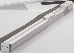

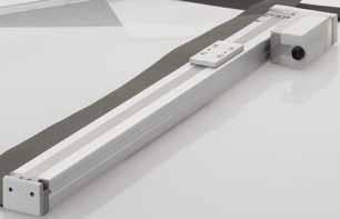

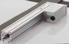


1 Space-saving installation Flexible motor mounting


2 compatible!! Pulse train input compatible Automatic actuator recognition Addition of new controller compatible with pulse trains Enables current position confirmation with position output With the adoption of ballscrew with lubrication equipment and liner guide with ball retainer, long-term maintenance-free operation is provided Allows 63 multi-point positioning Smallest controller class in the industry


3 Electric Slider Actuator Electric Rod Actuator Flexible motor mounting Space savings from various motor mountings to fit your equipment With the Handy Terminal, setting the PC software "E Tools" has never been easier In addition to the conventional straight type, a selection of right-hand, left-hand and bottom are available Simple operation with Handy Terminal Easy, even for beginners Right-hand Left-hand Bottom

 Refer to page 41 PLC Controlle EC07/EC63/ECPT Refer to pages 29 to 38 I/O Cable Refer to page 42 Handy terminal ETP2 Refer to pages 39 to 40 (Sold separately) Power")
4 System configuration Basic setting items Basic driving methods 1. Set the necessary parameters from a PC or handy terminal 2. Set the point data in a similar manner 1. Input a destination point signal from a PLC 2. Input a start signal from a PLC 3. After it is driving, output a positioning complete signal from the controller The areas indicated by the thin lines should be prepared by the customer. Surge protector (Sold separately) Refer to page 41 PLC Controlle EC07/EC63/ECPT Refer to pages 29 to 38 I/O Cable Refer to page 42 Handy terminal ETP2 Refer to pages 39 to 40 (Sold separately) Power supply Ground 24 VDC power supply PC communication cable (sold separately) EC-CBLPC1 Refer to page 41 PC Ground Noise filter (Sold separately) Refer to page 41 Ground RS485 interface Motor encoder relay cable (Fixed, movable) Refer to page 42 Actuator ERL2 Series Refer to pages 1 to 11 Actuator ESD2 Series Refer to pages 13 to 27 Ground Ground Configuration (When selecting the set model No.) Standard configuration Name Quantity Actuator unit 1 Controller unit 1 I/O Cable 1 Motor encoder relay cable 1 A surge protector is required to comply with the CE marking. Refer to the Instruction Manual for details about installation and wiring. Part used Model No. Manufacturer Surge protector R/A/V-781BXZ-4 R/A/V-781BWZ-4 RSPD-250-Q4 RSPD-250-U4 OKAYA ELECTRIC INDUSTRIES CO., LTD. Setting tools We offer the "ETP2" handy terminal. We offer the "E Tools" electric actuator setting software. (Windows version provided free of charge) You can set the point data and parameters for the ERL2/ESD2 electric actuators and issue operation instructions from a PC. The point data and parameter data can be saved to the PC. An RS-485 interface and a PC communication cable (EC-CBLPC1) are required for a PC connection. Recommended RS-485 interface model numbers MISUMI PCCM-COM-1PDUSBH-R CONTEC COM-1PD (USB) H Note 1: Because the PC communication cable is designed specifically for CKD's electric actuator, commercially available communication cables cannot be used. Accidentally using the wrong cable may damage the controller and PC. Note 2: The handy terminal and PC are expected to only be connected when making adjustments. Remove the cable from the controller during normal operation. Note 3: The PC may be unable to recognize the RS485 interface when recovering from sleep mode, and communication anomalies may occur. Intro 1


5 "E Tools" electric actuator setting software Note: An RS-485 interface and a separate PC communication cable (page 41) are required to connect the PC and controller. Download the "E Tools" electric actuator setting software and the Instruction Manual from the CKD website. Website address: Main functions You can easily set multiple point data settings. Monitor Actuator operational status Input and output status of the general purpose input and output Check the alarm history stored on the controller Settings Easy editing and setting of point data and parameters Operation instructions You can perform the following manual operations from E Tools Jog Inching Point movement Forced output to the general purpose output Intro 2
 ERL2-45E06 ERL2-45R06 ERL2-45L06 50 100 150 200 250 300 350 400 450 500 ERL2-45D06 ERL2-45E12 ERL2-45R12 ERL2-45L12 Slider")

6 Selection guide Type Model No. Stroke (mm) ERL2-45E06 ERL2-45R06 ERL2-45L ERL2-45D06 ERL2-45E12 ERL2-45R12 ERL2-45L12 Slider ERL2-45D12 ERL2-60E06 ERL2-60R06 ERL2-60L06 ERL2-60D06 ERL2-60E12 ERL2-60R12 ERL2-60L12 ERL2-60D12 Rod ESD2-35E06 ESD2-35R06 ESD2-35L06 ESD2-35D06 ESD2-35E12 ESD2-35R12 ESD2-35L12 ESD2-35D12 ESD2-45E06 ESD2-45R06 ESD2-45L06 ESD2-45D06 ESD2-45E12 ESD2-45R12 ESD2-45L12 ESD2-45D12 ESD2-55E06 ESD2-55R06 ESD2-55L06 ESD2-55D06 ESD2-55E12 ESD2-55R12 ESD2-55L12 ESD2-55D12 Intro 3
7 Max. load capacity (kg) Horizontal Vertical Lead (mm) Max. pressing force (N) Max. speed (mm/s) Listed page (*1) (*1) (*1) (*1) (*2) (*2) (*2) (*2) (*2) (*2) *1: Use within the allowable moment. *2: The values for the rod horizontal load capacity are based on an actuator used in combination with an external guide. Intro 4

8 Electric actuator Slider ERL2 Series Compatibility function allows the controller, actuator, and cable to be freely combined The electric actuator that works like a pneumatic cylinder Motor sizes: 42 / 56 Actuator specifications Descriptions ERL2-45 ERL2-60 Actuator Slider Motor Stepping motor Encoder Incremental Drive system Rolling ball screw Rolling ball screw Outer diameter 8 mm Outer diameter 12 mm Motor size mm Screw lead mm Stroke mm 50, 100, 150, , 100, 150, , 300, 350, , 300, 350, , 500, 550, , Operation speed range mm/s 15 to to to to 400 Operation acceleration/deceleration speed range m/s to 3.0 Repeatability mm ±0.02 Lost motion mm 0.1 or less Max. load capacity Horizontal kg *1 Vertical kg Maximum pressing force *2 N Motor power supply voltage 24 VDC±10% Motor section maximum instantaneous current A Type Non-excitation operation Brake Power supply voltage 24 VDC±10% Power consumption W Holding force N Insulation resistance 10 MΩ or higher 500 VDC Withstand voltage 500 VAC for 1 minute Operating ambient temperature 0 to 40 C (no freezing) Operating ambient humidity 35 to 80% RH (no condensation) Storage ambient temperature -10 to 50 C (no freezing) Storage ambient humidity 35 to 80% RH (no condensation) Atmosphere No corrosive gas, explosive gas, or dust Degree of protection IP4X *1: The maximum load capacity decreases when the speed increases. For more details, refer to the vertical and horizontal load capacity charts and graphs in the next page. *2: Use within the allowable moment. (Refer to page 46 for the allowable moment value.) Weight Body size ERL2-45 ERL2-60 Motor Mounting direction E R/L/D E R/L/D (kg) 50 st 100 st 150 st 200 st 250 st 300 st 350 st 400 st 450 st 500 st 550 st 600 st 700 st (1.8) (1.9) (2.0) (2.1) (2.2) (2.3) (2.4) (2.5) (2.6) (2.8) (2.0) (2.1) (2.2) (2.3) (2.4) (2.5) (2.6) (2.7) (2.8) (3.0) (3.8) (4.0) (4.2) (4.4) (4.6) (4.8) (5.0) (5.2) (5.4) (5.6) (5.8) (6.0) (6.4) (4.3) (4.5) (4.7) (4.9) (5.1) (5.3) (5.5) (5.7) (5.9) (6.1) (6.3) (6.5) (6.9) Note: the numbers in ( ) indicate the product weight with the brake 1
9 Vertical load capacity ERL2-45 ERL2 Series Vertical load capacity, horizontal load capacity, pressing force ERL Load capacity (kg) Lead 6 Lead Speed (mm/s) 800 Load capacity (kg) Lead 6 Lead Speed (mm/s) Horizontal load capacity ERL2-45 ERL Load capacity (kg) Lead 6 Lead 12 Load capacity (kg) Lead 6 Lead Speed (mm/s) Speed (mm/s) Pressing force ERL2-45 ERL Pressing force (N) Lead 6 Lead Pressing current set value (%) Pressing force (N) Lead 6 Lead Pressing current set value (%) Note: Use within the allowable moment. Note: Use within the allowable moment. 2
10 ERL2 Series 3 How to order Set model No. (actuator, controller, cable) ERL2 Model No. 60 E B M RX B 2 A Body size B Motor mounting direction C Screw lead [Example of model No.] ERL2-60E06-50BM-RXB2 D Stroke A Body size : 60 B Motor mounting direction : standard mounting (straight) C Screw lead : 6 mm D Stroke : 500 mm E Brake : with brake F Origin position : motor side G Relay cable length : movable cable 10 m H Controller : EC07 DIN mounting rail I I/O Cable length : 2 m *1: When H controller is set to "N", also select "N" for I I/O cable. Actuator body discrete model No. ERL2 A Body size Controller individual model No. EC E B M B Motor mounting direction C Screw lead D Stroke B Series Mounting method * For details, refer to "How to order" on page 29. E Brake E Brake F Origin position G Relay cable length N0 N N F Origin position I H Controller I/O Cable length Code A Body size 45 Body size Body size 60 B C D E F Content Motor mounting direction E Standard mounting (straight) R Right-hand mounting L Left-hand mounting D Bottom mounting Screw lead 06 6 mm mm Stroke Code Length mm mm mm mm mm mm mm mm mm mm mm mm mm Brake N B Without brake With brake Origin position M Motor side F Opposite side of the motor G Relay cable length N0 None S1 Fixing cable 1 m S3 Fixing cable 3 m S5 Fixing cable 5 m SX Fixing cable 10 m R1 Movable cable 1 m R3 Movable cable 3 m R5 Movable cable 5 m RX Movable cable 10 m H I Body size/motor mounting direction 45E/45R/45L 45D 60E/60R/60L 60D Controller N None *1 A EC07 standard mounting B EC07 DIN rail mount C EC63 standard mounting D EC63 DIN rail mount E ECPT standard mounting *2 F ECPT DIN rail mount *2 I/O Cable length N None 2 2 m 3 3 m *3 5 5 m *3 *2: Use a PLC unit which meets the ECPT pulse train signal input specifications (refer to page 34). *3: If the code for the controller is E or F, these cables can be used only when the differential system is used as the pulse train signal system. Only a cable length of 2 m can be used with the open collector system. Cable discrete model No. Relay cable I/O Cable EC CBLME1 *Refer to page 42 for details. S 5 Fixed/movable Cable length EC CBLIF Cable length Controller Series
11 Dimensions ERL2 Series How to order/dimensions ERL2-45E (standard mounting straight) ± ± THRU Connect to relay cable 9 (20) Long through hole 4-M4 depth φ 3H7 depth Fixing cable allowable bending R50 (300) Stroke length: X (8) Note 1 (8) Note 1 4-M2.6 depth Body length: LL (49) Ground terminal M3 depth Total length: L 13.5 [53.5] Note 2 19 N 100 P-M4 depth 8 Note 1: Operating range during origin return Note 2: The numbers within the [ ] are the dimensions with the brake Stroke Code X (mm) Total length L Without brake (mm) With brake Body length LL (mm) L3 (mm) L4 (mm) Number of mounting holes P Number of mounting hole intervals N Weight (kg) Without brake With brake
12 ERL2 Series Dimensions ERL2-45R (right-hand mounting) (8) Note 1 Stroke: X (8) Note Total length: L Body length: LL through slot 15±0.05 L φ4.5 through M4 depth 10 (Fixing tap for the slider edge) Note ± (107 to 109) M4 depth φ3H7 depth [57] Note 2 (300) Grounding terminal M3 depth 6 (20) Fixing cable Allowable bend R50 (49) Connect to the relay cable A View A 4 P-M4 depth 8 (Fixing tap for the slider bottom) Note 3 19 N 100 Note 1: Operating range during origin return Note 2: The numbers within the [ ] are the dimensions with the brake Note 3: Be sure to also mount and use the fixing tap for the slider bottom when using the fixing tap for the slider edge. Stroke Code X (mm) Total length L (mm) Body length LL (mm) L3 (mm) Number of mounting holes P Number of mounting hole intervals N Weight (kg) Without brake With brake
13 Dimensions ERL2 Series Dimensions ERL2-45L (left-hand mounting) 19 N P-M4 depth 8 (Fixing tap for the slider bottom) Note 3 (20) A (49) Connect to the relay cable Fixing cable Grounding terminal M3 depth 6 Allowable bend R50 A View φ3H7 depth [57] Note M4 depth ±0.05 (300) (107 to 109) through slot ± φ4.5 through M4 depth 10 (Slider edge fixing tap) Note 3 12 L3 Body length: LL Total length: L 29 Stroke: X (8) Note 1 (8) Note 1 Note 1: Operating range during origin return Note 2: The numbers within the [ ] are the dimensions with the brake Note 3: Be sure to also mount and use the fixing tap for the slider bottom when using the fixing tap for the slider edge. Stroke Code X (mm) Total length L (mm) Body length LL (mm) L3 (mm) Number of mounting holes P Number of mounting hole intervals N Weight (kg) Without brake With brake
14 ERL2 Series Dimensions ERL2-45D (bottom mounting) Total length: L Body length: LL ± ± through slot 4-M4 depth φ3H7 depth (8) Note 1 Stroke: X (8) Note M4 depth 10 (Slider edge 33 fixing tap) Note (20) A View P-M4 depth 8 (Fixing tap for the slider bottom) Note 3 14 A (300) (49) 93.5 Connect to the relay cable Fixing cable Allowable bend R [57] Note 2 Grounding terminal M3 depth N Note 1: Operating range during origin return Note 2: The numbers within the [ ] are the dimensions with the brake Note 3: Be sure to also mount and use the fixing tap for the slider bottom when using the fixing tap for the slider edge. Stroke Code X (mm) Total length L (mm) Body length LL (mm) Number of mounting holes P Number of mounting hole intervals N Weight (kg) Without brake With brake
15 Dimensions ERL2 Series Dimensions ERL2-60E (standard mounting straight) ± ±0.05 (φ 3 Dimensions) THRU Connect to relay cable 9 52 (20) 2-Long through hole 4-M5 depth 10 4-φ3H7 depth L3 35 (300) (8) Note 1 Stroke length: X (8) Note L4 4-M2.6 depth 3 Body length: LL Total length: L 4 Ground terminal M3 depth [55] Note (49) Fixing cable allowable bending R50 16 P-M5 depth 9 33 N 100 Note 1: Operating range during origin return Note 2: The numbers within the [ ] are the dimensions with the brake Stroke Code X (mm) Total length L Without brake (mm) With brake Body length LL (mm) L3 (mm) L4 (mm) Number of mounting holes P Number of mounting hole intervals N Weight (kg) Without brake With brake
16 ERL2 Series Dimensions ERL2-60R (right-hand mounting) (8) Note 1 (8) Note 1 Stroke: X Total length: L Body length: LL L ± M5 depth 12 (Fixing tap for the slider edge) Note 3 4-φ5.5 through through slot 39 31± (140.5 to 142.5) M5 depth φ3H7 depth [61] Note 2 Grounding terminal M3 depth 6 (20) A View A (49) Fixing cable Allowable bend R50 Connect to the relay cable (300) 4 P-M5 depth 9 (Fixing tap for the slider bottom) Note 3 33 N 100 Note 1: Operating range during origin return Note 2: The numbers within the [ ] are the dimensions with the brake Note 3: Be sure to also mount and use the fixing tap for the slider bottom when using the fixing tap for the slider edge. Stroke Code X (mm) Total length L (mm) Body length LL (mm) L3 (mm) Number of mounting holes P Number of mounting hole intervals N Weight (kg) Without brake With brake
17 Dimensions ERL2 Series Dimensions ERL2-60L (left-hand mounting) Connect to the relay cable (49) A (20) 27 Grounding terminal M3 depth 6 A View Fixing cable Allowable bend R50 (300) 4 19 [61] Note through slot 6 (140.5 to 142.5) ± M5 depth φ3H7 depth L3 35 Body length: LL Total length: L 4-φ5.5 through M5 depth 12 (Slider edge fixing tap) Note 3 Stroke: X (8) Note 1 (8) Note 1 33 N ± P-M5 depth 9 (Fixing tap for the slider bottom) Note 3 Note 1: Operating range during origin return Note 2: The numbers within the [ ] are the dimensions with the brake Note 3: Be sure to also mount and use the fixing tap for the slider bottom when using the fixing tap for the slider edge. Stroke Code X (mm) Total length L (mm) Body length LL (mm) L3 (mm) Number of mounting holes P Number of mounting hole intervals N Weight (kg) Without brake With brake
18 ERL2 Series Dimensions ERL2-60D (bottom mounting) Total length: L Body length: LL ± φ5.5 through through slot 39 31± φ3H7 depth 10 4-M5 depth 10 Stroke: X (8) Note 1 (8) Note M5 depth 12 (Slider edge fixing tap) Note (136.5 to 138.5) [61] Note 2 (20) P-M5 depth 9 (Fixing tap for the slider bottom) Note 3 Connect to the relay cable A (49) Fixing cable Allowable bend R50 Grounding terminal M3 depth 6 A View N 100 (300) 4 Note 1: Operating range during origin return Note 2: The numbers within the [ ] are the dimensions with the brake Note 3: Be sure to also mount and use the fixing tap for the slider bottom when using the fixing tap for the slider edge. Stroke Code X (mm) Total length L (mm) Body length LL (mm) Number of mounting holes P Number of mounting hole intervals N Weight (kg) Without brake With brake
19 ERL2 Optional parts ERL2 Series Dimensions, optional parts Use the following slider spacer kit with the ERL2 if the workpiece mounted on the slider interferes with the motor. Slider spacer kit: SSP ERL2-45 model number: EA-45-SSP Dimensions (49.8) 2-φ3H7 depth 7 4-M4 depth ± ERL2-60 model number: EA-60-SSP Dimensions (66.8) 2-φ3H7 depth 7 4-M5 depth ± ±0.05 8±

20 Electric actuator Rod ESD2 Series Compatibility function allows the controller, actuator and cable to be freely combined The electric actuator that works like a pneumatic cylinder Motor sizes: 42 / 56 Actuator specifications Actuator Motor Encoder Drive system Descriptions ESD2-35 ESD2-45 ESD2-55 Rod Stepping motor Incremental Rolling ball screw Outer diameter 8 mm Rolling ball screw Outer diameter 12 mm Motor size Screw lead mm Stroke mm 50, 100, , 100, 150, , 100, 150, , 300 Operation speed range mm/s 15 to to to to to to 400 Operation acceleration/deceleration speed range m/s to 3.0 Repeatability mm ±0.02 Lost motion mm 0.1 or less Max. load capacity Horizontal kg *1 Vertical kg Maximum pressing force N Motor power supply voltage 24 VDC±10% Motor section maximum instantaneous current A Type Non-excitation operation Brake Power supply voltage 24 VDC±10% Power consumption W Holding force N Insulation resistance 10 MΩ or higher 500 VDC Withstand voltage 500 VAC for 1 minute Operating ambient temperature 0 to 40 C (no freezing) Operating ambient humidity 35 to 80% RH (no condensation) Storage ambient temperature -10 to 50 C (no freezing) Storage ambient humidity 35 to 80% RH (no condensation) Atmosphere No corrosive gas, explosive gas, or dust Degree of protection IP4X *1: The maximum load capacity decreases when the speed increases. For more details, refer to the vertical and horizontal load capacity charts and graphs in the next page. In addition, a static or dynamic load moment cannot be applied to the rod. Use a linear guide, etc., to prevent a radial load from being placed on the rod. Weight Body size Motor mounting direction 50 st 100 st 150 st 200 st 250 st 300 st E (1.7) (1.9) (2.0) ESD R/L/D (1.8) (2.0) (2.1) E (2.1) (2.4) (2.6) (2.9) ESD R/L/D (2.2) (2.5) (2.7) (3.0) E (3.7) (4.1) (4.5) (4.8) (5.2) (5.6) ESD R/L/D (4.1) (4.5) (4.9) (5.2) (5.6) (6.0) Note: the numbers in ( ) indicate the product weight with the brake (kg) 13
21 Vertical load capacity ESD2-35, 45 ESD2 Series Vertical load capacity, horizontal load capacity, pressing force ESD Load capacity (kg) Lead 6 Lead Speed (mm/s) 800 Load capacity (kg) Lead 6 Lead Speed (mm/s) Horizontal load capacity ESD2-35, 45 ESD Load capacity (kg) Lead 6 Lead Speed (mm/s) 800 Load capacity (kg) Lead 6 Lead Speed (mm/s) Pressing force ESD2-35, 45 ESD Pressing force (N) Lead 6 Lead 12 Pressing force (N) Lead 6 Lead Pressing current set value (%) Pressing current set value (%) 14
22 ESD2 Series How to order Set model No. (actuator, controller, cable) ESD2 Model No. 55 E N F S1 A 2 F C Screw lead [Example of model No.] ESD2-55E12-05NF-S1A2F D Stroke *1: When G controller is set to "N", also select "N" for H I/O cable. F Origin position A Body size : 55 B Motor mounting direction : standard mounting (straight) C Screw lead : 12 mm D Stroke : 50 mm E Brake : without brake F Origin position : opposite side of the motor G Relay cable length : fixed cable 1 m H Controller : EC07 standard mounting I I/O Cable length : 2 m J Mounting bracket : flange bracket included Actuator body discrete model No. ESD2 55 E N F B Motor mounting E Brake direction C Screw lead F Origin position A Body size D Stroke Mounting method Series *For details, refer to "How to order" on page G Relay cable length H Controller N0 N N N I I/O Cable length J Mounting bracket Code Content A Body size 35 Body size Body size Body size 55 B Motor mounting direction E Standard mounting (straight) R Right-hand mounting L Left-hand mounting D Bottom mounting C Screw lead 06 6 mm mm D Stroke Code Length E F G H I J mm mm mm mm mm mm Brake N Without brake B With brake Origin position M Motor side F Relay cable length Fixed/movable Cable length *Refer to page 42 for details. Opposite side of the motor N0 None S1 Fixed cable 1 m S3 Fixed cable 3 m S5 Fixed cable 5 m SX Fixed cable 10 m R1 Movable cable 1 m R3 Movable cable 3 m R5 Movable cable 5 m RX Movable cable 10 m Body size Controller N None *1 A EC07 standard mount B EC07 DIN rail mount C EC63 standard mount D EC63 DIN rail mount E ECPT standard mount *2 F ECPT DIN rail mount *2 I/O Cable length N None 2 2 m 3 3 m *3 5 5 m *3 Mounting bracket N None L Foot bracket included F Flange bracket included S Spacer (body size 35, 55 only) Controller individual model No. Cable discrete model No. Relay cable I/O Cable EC 07 A Body size B B Motor mounting direction E Brake EC CBLME1 *2: Use a PLC unit which meets the ECPT pulse train signal input specifications (refer to page 34). *3: If the code for the controller is E or F, these cables can be used only when the differential system is used as the pulse train signal system. Only a cable length of 2 m can be used with the open collector system. S 5 EC CBLIF Cable length Controlle Series
23 Dimensions ESD2 Series How to order/dimensions ESD2-35E (standard mounting straight) Connect to relay cable (20) (hexagon: direction is variable against the base side) 9 M φ16 (15) Dimension of attached nut 4-M3 depth 10 (90 equipartition) P.C.D.φ 29 M Ball screw greasing possible position: 73 mm or over Stroke length: X Ball screw greasing hole 37.5 (for the origin position) (when using spacer brackets) Ground terminal Spacer bracket (optional product) M3 depth Body length: LL (for the origin position) [64] Note 2 Total length: L (for the origin position) (49) Fixing cable allowable bending R50 (300) (with using spacer) (8) Note 1 (8) Note N 50 P-M3 depth 4 Note 1: Operating range during origin return Note 2: The numbers within the [ ] are the dimensions with the brake Stroke Code X (mm) Total length L Without brake (mm) With brake Body length LL (mm) Number of mounting holes P Number of mounting hole intervals N Weight (kg) Without brake With brake
24 ESD2 Series Dimensions ESD2-35R (right-hand mounting) P.C.D M3 depth 10 (90 evenly spaced) φ Total length: L (from the origin position) Body length: LL (from the origin position) 7.5 (width across flat area: orientation with the base is not fixed) M4 depth 10 (Rod edge fixing tap) Note M Ball screw greasable position: 73 mm or more Connect to the relay cable Fixing cable allowable bend R (from the origin position) (49) A (20) M Stroke: X Grounding terminal M3 depth 6 Attached nut dimensions (8) Note 1 (8) Note 1 (300) A View 25 Ball screw greasing hole (105 to 107) (15) [57] Note 2 41 N 50 P-M3 depth 4 (Rod bottom fixing tap) Note 3 Note 1: Operating range during origin return Note 2: The numbers within the [ ] are the dimensions with the brake Note 3: Be sure to also mount and use the fixing tap for the rod bottom when using the fixing tap for the rod edge. Stroke Code X (mm) Total length L (mm) Body length LL (mm) Number of mounting holes P Number of mounting hole intervals N Weight (kg) Without brake With brake
25 Dimensions ESD2 Series Dimensions ESD2-35L (left-hand mounting) 41 N 50 P-M3 depth 4 (Rod bottom fixing tap) Note [57] Note 2 M (from the origin position) Stroke: X (300) (15) 25.5 Attached nut dimensions (8) Note 1 (8) Note 1 Fixing cable Allowable bend R50 Connect to the relay cable (49) A 4 Grounding terminal M3 depth 6 A View (20) M3 depth 10 (90 evenly spaced) P.C.D.29 Ball screw greasable position: 73 mm or more M Ball screw greasing hole (105 to 107) M4 depth 10 (Rod edge fixing tap) Note (width across flat area: orientation with the base surface is not fixed) Body length: LL (from the origin position) Total length: L (from the origin position) Note 1: Operating range during origin return Note 2: The numbers within the [ ] are the dimensions with the brake Note 3: Be sure to also mount and use the fixing tap for the rod bottom when using the fixing tap for the rod edge. Stroke Code X (mm) Total length L (mm) Body length LL (mm) Number of mounting holes P Number of mounting hole intervals N Weight (kg) Without brake With brake
26 ESD2 Series Dimensions ESD2-35D (bottom mounting) Ball screw greasing hole 4-M3 depth 10 (90 evenly spaced) Total length: L (from the origin position) Body length: LL (from the origin position) 7.5 (width across flat area: orientation with the base surface is not fixed) M4 depth 10 (Rod edge fixing tap) Note 3 P.C.D M Ball screw greasable position: 73 mm or more (105 to 107) (from the origin position) 17 [57] Note 2 13 Stroke: X 41 N M (15) 25 Attached nut dimensions (8) Note 1 (8) Note 1 P-M3 depth 4 (Rod bottom fixing tap) Note 3 (300) (49) Fixing cable 4 Allowable bend R50 A Connect to the relay cable Grounding terminal M3 depth 6 A View (20) Note 1: Operating range during origin return Note 2: The numbers within the [ ] are the dimensions with the brake Note 3: Be sure to also mount and use the fixing tap for the rod bottom when using the fixing tap for the rod edge. Stroke Code X (mm) Total length L (mm) Body length LL (mm) Number of Without brake mounting holes P With brake Number of mounting hole intervals N Weight (kg) Without brake With brake Without brake With brake
27 Dimensions ESD2 Series Dimensions ESD2-45E (standard mounting straight) Connect to relay cable M φ (hexagon: direction is variable against the base side) Dimension of attached nut M Ball screw greasing possible position: 75 mm or over Ball screw greasing hole M4 depth Stroke length: X (5) Note 1 (5) Note (for the origin position) T groove for M3 (8 positions) Section D P.C.D.53 Ground terminal 3.5 M3 depth 6 T groove range: L Body length: LL (for the origin position) Total length: L (for the origin position) 13.5 [64] Note (49) (20) Fixing cable allowable bending R50 (300) D section details Note 1: Operating range during origin return Note 2: The numbers within the [ ] are the dimensions with the brake Stroke Code X (mm) Total length L Without brake (mm) With brake Body length LL (mm) T slot range L3 (mm) Weight (kg) Without brake With brake
28 ESD2 Series Dimensions ESD2-45R (right-hand mounting) D section details 42.5 (from the origin position) 4-M4 depth 10 Stroke: X Total length: L (from the origin position) Body length: LL (from the origin position) T slot range: T M4 depth 10 (Rod edge fixing tap) Note M3 T slot (8 locations) Note 3 (8) Note 1 (8) Note 1 P.C.D.53 D section Ball screw greasing hole (105 to 107) (107 to 109) [57] Note 2 M φ (width across flat area: orientation with the base is not fixed) 18 M Ball screw greasable position 75 mm or more Fixing cable allowable bend R50 Attached nut dimensions Connect to the relay cable (49) (19.6) (300) A 4 A View (20) Grounding terminal M3 depth 6 Note 1: Operating range during origin return Note 2: The numbers within the [ ] are the dimensions with the brake Note 3: Be sure to also mount and use the M3 T slot when using the fixing tap for the rod edge. Stroke Code X (mm) Total length L (mm) Body length LL (mm) T slot range L3 (mm) Weight (kg) Without brake With brake
29 Dimensions ESD2 Series Dimensions ESD2-45L (left-hand mounting) M φ (width across flat area: orientation with the base is not fixed) (19.6) Attached nut dimensions M Ball screw greasable position: 75 mm or more (300) Fixing cable allowable bend R50 Connect to the relay cable (49) A 4 Grounding terminal (20) M3 depth 6 A View 17 [57] Note P.C.D.53 (8) Note 1 (8) Note 1 Ball screw greasing hole M3 T slot (8 locations) Note 3 4-M4 depth (from the origin position) Stroke: X T slot range: T3 Body length: LL (from the origin position) Total length: L (from the origin position) M4 depth 10 (Rod edge fixing tap) Note D section (107 to 109) D section details Note 1: Operating range during origin return Note 2: The numbers within the [ ] are the dimensions with the brake Note 3: Be sure to also mount and use the M3 T slot when using the fixing tap for the rod edge. Stroke Code X (mm) Total length L (mm) Body length LL (mm) T slot range L3 (mm) Weight (kg) Without brake With brake
30 ESD2 Series Dimensions ESD2-45D (bottom mounting) Ball screw greasing hole P.C.D M4 depth 10 Stroke: X 42.5 (from the origin position) Total length: L (from the origin position) Body length: LL (from the origin position) T slot range: T M4 depth 10 (Rod edge fixing tap) Note 3 M3 T slot (8 locations) Note 3 D section (8) Note 1 (8) Note 1 (107 to 109) [57] Note D section details (width across flat area: orientation with the base is not fixed) M φ 20 (19.6) Attached nut dimensions M Ball screw greasable position: 75 mm or more Fixing cable allowable bend R50 (300) A 4 25 Grounding terminal (20) M3 depth 6 A View Connect to the relay cable (49) Note 1: Operating range during origin return Note 2: The numbers within the [ ] are the dimensions with the brake Note 3: Be sure to also mount and use the M3 T slot when using the fixing tap for the rod edge. Stroke Code X (mm) Total length L (mm) Body length LL (mm) T slot range L3 (mm) Weight (kg) Without brake With brake
31 Dimensions ESD2 Series Dimensions ESD2-55E (standard mounting straight) M φ (hexagon: direction is variable against the base side) Connect to relay cable 9 (20) (21.9) P.C.D [66] Note (49) 4-M5 depth 12 Dimension of attached nut M Ball screw greasing possible position: 83 mm or over Stroke length: X (8) Note 1 (8) Note 1 Ball screw greasing hole 45.5 (for the origin position) 23 Fixing cable allowable bending R50 (300) 72 (when using spacer brackets) 23 T groove for M4 (8 positions) Section D 29.5 (with using spacer) 2 20 Spacer bracket (optional product) T groove range: L3 Body length: LL (for the origin position) Total length: L (for the origin position) 4 Ground terminal M3 depth D section details Note 1: Operating range during origin return Note 2: The numbers within the [ ] are the dimensions with the brake Stroke Code X (mm) Total length L Without brake (mm) With brake Body length LL (mm) T slot range L3 (mm) Weight (kg) Without brake With brake
32 ESD2 Series Dimensions ESD2-55R (right-hand mounting) M5 depth 12 M4 T slot (8 locations) P.C.D.65 Ball screw greasable position 83 mm or more 9.5 (width across flat area: 24 orientation with the base is not fixed) φ 25 Ball screw greasing hole 4-M5 depth 12 (Rod edge fixing tap) Note D section Ball screw greasing hole Connect to the relay cable (300) A (136 to 138) (20) (49) 7.3 A View Fixing cable Allowable bend R [61] Note 2 M D section details (from the origin position) 117 Stroke: X (8) Note 1 (8) Note 1 30 Grounding terminal M3 depth (21.9) Attached nut dimensions T slot range: L3 Body length: LL (from the origin position) Total length: L (from the origin position) Note 1: Operating range during origin return Note 2: The numbers within the [ ] are the dimensions with the brake Note 3: Be sure to also mount and use the M4 T slot when using the fixing tap for the rod edge. Stroke Code X (mm) Total length L (mm) Body length LL (mm) T slot range L3 (mm) Weight (kg) Without brake With brake
33 Dimensions ESD2 Series Dimensions ESD2-55L (left-hand mounting) Total length: L (from the origin position) Body length: LL (from the origin position) T slot range: L M (21.9) Attached nut dimensions (8) Note 1 (8) Note 1 Stroke: X 45.5 (from the origin position) Grounding terminal M3 depth 6 19 [61] Note 2 (20) Connect to the relay cable A View (300) A M (49) Fixing cable Allowable bend R (136 to 138) M4 T slot (8 locations) 4-M5 depth P.C.D.65 D section φ Ball screw greasable position 83 mm or more 9.5 (width across flat area: orientation with the base is not fixed) 4-M5 depth 12 (Rod edge fixing tap) Note 3 16 Ball screw greasing hole D section details Note 1: Operating range during origin return Note 2: The numbers within the [ ] are the dimensions with the brake Note 3: Be sure to also mount and use the M4 T slot when using the fixing tap for the rod edge. Stroke Code X (mm) Total length L (mm) Body length LL (mm) T slot range L3 (mm) Weight (kg) Without brake With brake
34 ESD2 Series Dimensions ESD2-55D (bottom mounting) Ball screw greasable position 83 mm or more M φ (width across flat area: orientation with the base is not fixed) (21.9) M Ball screw greasing hole Attached nut dimensions 4-M5 depth 12 M4 T slot (8 locations) P.C.D (from the origin position) Stroke: X (8) Note 1 (8) Note 1 Total length: L (from the origin position) Body length: LL (from the origin position) T slot range: L M5 depth 12 (Rod edge fixing tap) Note D section (136 to 138) [61] Note (20) (300) (49) Connect to the relay cable A Fixing cable allowable bend R50 Grounding terminal M3 depth A View D section details 4 Note 1: Operating range during origin return Note 2: The numbers within the [ ] are the dimensions with the brake Note 3: Be sure to also mount and use the M4 T slot when using the fixing tap for the rod edge. Stroke Code X (mm) Total length L (mm) Body length LL (mm) T slot range L3 (mm) Weight (kg) Without brake With brake
35 Option (mounting bracket) ERL2/ESD2 Series Option (mounting bracket) The following kits are included with the product with the mounting bracket option. Option : LB Foot kit model No.: ESD-[Body size]-lb Foot bracket fitting dimensions Set model No.: ESD2-35E - - L 12 2-φ5 Option : FA Flange kit model No.: ESD-[Body size]-fa Flange bracket fitting dimensions Set model No.: ESD2-35E - - F φ5 41 L L2-φ5 4-φ Total length (mm) 41 Stroke L L Set model No.: ESD2-45E - - F 7 Set model No.: ESD2-45E - - L 15 2-φ φ6 (7.5) (L) 4-φ (7.5) (L) 20 Total length (mm) Stroke L φ Set model No.: ESD2-55E - - F Set model No.: ESD2-55E - - L 20 2-φ (10) (L) φ (10) (L) Total length (mm) Stroke L Option : SP Spacer kit model No.: ESD-[ ]-SP Set model No.: ESD2-[ ]E - - S * Refer to the spacer bracket fitting dimensions on pages 16 and
36 Controlle EC Series Connectable actuator: ERL2 / ESD2 Features Compact, lightweight, thin (body width of 35 mm) Configurable without a manual Equipped with an automatic actuator recognition function PC software compatible Flexible control (ECPT) Position, speed, acceleration and deceleration can be changed in real time Unlimited number of positioning points Equipped with a position output function (ECPT) Current position can be detected in real time Specifications How to order EC 07 B A Series B Mounting method Code Content A Series 07 7-point positioning point positioning PT Pulse train input positioning B Mounting method A EC07 standard mount B EC07 DIN rail mount C EC63 standard mount D EC63 DIN rail mount E ECPT standard mount F ECPT DIN rail mount Descriptions Series EC07 EC63 ECPT Applicable motor size 42, 56 Setting method Configure with a handy terminal or PC software Solenoid mode Solenoid mode Pulse train control mode PIO Mode (Single/double 2-position, 3-position) (Single/double 2-position, 3-position) Pulse/direction Simplified mode (3 points) Simplified mode (7 points) UP/DOWN Standard mode (7 points) Standard mode (63 points) A/B phase (4 multiplier) Body lamps Green: motor power (not powered when blinking)/red: alarm generated Number of inputs 7 points (photo coupler insulation) 10 points (photo coupler insulation) 7 points (Except for the photo coupler insulation, pulse train input terminal) Output points 7 points (photo coupler insulation) 12 points (photo coupler insulation) 9 points (Except for the photo coupler insulation, current position output terminal) Motor power supply voltage 24 VDC±10% Motor section maximum instantaneous current 42: 2.7 A, 56: 4 A Control power supply voltage 24 VDC±10% Control section current consumption 300 ma or less (including the ETP2 current consumption) Brake Power supply voltage 24 VDC±10% Power consumption Refer to the specifications for each actuator Insulation resistance 100 MΩ or higher 500 VDC Withstand voltage 1000 VAC for 1 minute Operating ambient temperature 0 to 40 C (no freezing) Operating ambient humidity 35 to 80% RH (no condensation) Storage ambient temperature -10 to 50 C (no freezing) Storage ambient humidity 35 to 80% RH (no condensation) Atmosphere No corrosive gas, explosive gas, or dust Degree of protection IP3X Weight Approx. 150 g (standard mount) Approx. 180 g (standard mount) Approx. 180 g (DIN rail mount) Approx. 210 g (DIN rail mount) 29
 to input and output the control signals.")
37 Panel description EC Series Panel description EC Indicator lamp I/O Connector 1 Indicator lamp Green: motor receiving power (not powered when blinking) Red: alarm condition SIO Connector Encoder connector Motor connector 2 3 I/O Connector Connect an external control device (PLC, etc.) to input and output the control signals. SIO Connector Connect a PC or handy terminal to set the parameters and perform manual operations. 6 Power supply connector 4 Encoder connector Connect a relay cable to input the encoder signals. 5 Motor connector Connect a relay cable to output the power signal to the motor. 6 Power supply connector Input a 24 VDC control power supply and motor power supply to the controller. EC63 ECPT 1 Indicator lamp 1 Indicator lamp 2 I/O Connector 2 I/O Connector 3 SIO Connector 3 SIO Connector 4 Encoder connector 4 Encoder connector 5 Motor connector 5 Motor connector 6 Power supply connector 6 Power supply connector Power supply connector *Power supply plug is an accessory. Power supply connector terminal Terminal name Function name Function description BK Brake release Apply 24 VDC when forcefully releasing the brake. MPI Motor power supply shutoff MPI and MPO are connected to the jumper wires at the time of shipment. A shutoff MPO Motor power supply shutoff turns off the motor power supply. 24 V Common power supply (+) Input common 24 VDC to the motor power supply and the control power supply. 0 V Common power supply (-) Connect common 0 VDC to the motor power supply, control power supply, brake release, and the emergency machine stop input. EMG Emergency machine stop input Connect the b contact emergency machine stop switch and input 24 VDC. Power supply plugs MPI MPO BK 24 V 0 V EMG 30
38 EC Series EC07 Wiring I/O cable specifications Descriptions Specifications Type 20-conductor cabtyre cord (UL94V-0) Sheath material Vinyl chloride Sheath diameter φ 8.4 Sheath color Gray Core wire 0.2 mm 2 (AWG24) annealed copper wire Lead wire exposure (ref.) Approx. 7 mm from the tip of the lead wire Circuit connection example Host system side Power supply 24 VDC 3.0 A (Motor 42) 4.3 A (Motor 56) 24 V 0 V Machine stops Reset switch CR MC *3 Emergency machine stop switch CR MC *3 Manual brake Controller side CN1 power supply connector release switch BK Brake release MC MPI Motor power *3 MPO supply shutoff 24 V Controller power supply + 0 V Controller power supply - CR EMG Emergency machine stop input Output side COM External power supply 24 VDC*2 - + I/O Cable Blue Input common +/- PLC output unit Output side - + General purpose input *1 General purpose input *1 General purpose input *1 General purpose input *1 Origin return instruction signal Servo ON signal Alarm reset instruction signal Light green Gray Purple Green Yellow Orange Brown General purpose input 1 General purpose input 2 General purpose input 3 General purpose input 4 Input 5 Input 6 Input 7 Input signal PLC input unit Input side COM Input side External power supply 24 VDC* General purpose output *1 General purpose output *1 General purpose output *1 General purpose output *1 Origin return complete signal Operation preparation complete signal Alarm signal (b contact connection) Blue (white line) Light green (white line) Gray (white line) Purple (white line) Green (white line) Yellow (white line) Orange (white line) Brown (white line) Output common +/- General purpose output 1 General purpose output 2 General purpose output 3 Output signal General purpose output 4 Output 5 Output 6 Output 7 31 Note: To prevent wiring mistakes, check before turning on the power. *1: Refer to the following table for the general purpose inputs/outputs. *2: The inputs and outputs both need an external power supply (24 VDC). The input and output COM can be used with either + or -. *3: For safety category support, connect the contact of an electromagnetic switch or other device to the MPI and MPO terminals when externally shutting off the motor drive. General purpose input/output assignments Control mode Standard mode 7 points Simplified mode 3 points Solenoid mode Double 2-position Double 3-position Single General purpose input 1 Point movement start Point 1 movement start Solenoid valve movement instruction 1 Solenoid valve movement instruction 1 General purpose input 2 Point selection bit 2 Point 2 movement start Solenoid valve movement instruction 2 Solenoid valve movement instruction 2 Solenoid valve movement instruction General purpose input 3 Point selection bit 1 Point 3 movement start General purpose input 4 Point selection bit 0 General purpose output 1 Point movement complete Point 1 movement complete Point 1 movement complete Point 1 movement complete Point 1 movement complete General purpose output 2 Point confirmation bit 2 Point 2 movement complete Point 2 movement complete Point 2 movement complete Point 2 movement complete General purpose output 3 Point confirmation bit 1 Point 3 movement complete Switch 1 output Switch 1 output Switch 1 output General purpose output 4 Point confirmation bit 0 Switch 2 output Switch 2 output Switch 2 output
39 EC63 Wiring I/O cable specifications Descriptions Specifications Type 28-conductor cabtyre cord (UL94V-0) Sheath material Vinyl chloride Sheath diameter φ 8.8 Descriptions Sheath color Core wire Lead wire exposure (ref.) EC Series Wiring Specifications Gray 0.2 mm 2 (AWG24) annealed copper wire Approx. 7 mm from the tip of the lead wire Circuit connection example Host system side Power supply 24 VDC 3.0 A (Motor 42) 4.3 A (Motor 56) 24 V 0 V Machine stops Reset switch CR MC *3 Emergency machine stop switch CR MC *3 Manual brake Controller side CN1 power supply connector release switch BK Brake release MC *3 MPI Motor power MPO supply shutoff 24 V Controller power supply + Output side COM External power supply 24 VDC*2 - + CR 0 V EMG I/O Cable Blue Controller power supply - Emergency machine stop input Input common +/- PLC output unit PLC input unit Output side Input side COM Input side - + General purpose input *1 General purpose input *1 General purpose input *1 General purpose input *1 General purpose input *1 General purpose input *1 General purpose input *1 Origin return instruction signal Servo ON signal Alarm reset instruction signal External power supply 24 VDC* General purpose output *1 General purpose output *1 General purpose output *1 General purpose output *1 General purpose output *1 General purpose output *1 General purpose output *1 Zone 1 signal Zone 2 signal Origin return complete signal Operation preparation complete signal Alarm signal (b contact connection) Light green General purpose input 1 Gray General purpose input 2 Purple General purpose input 3 Green General purpose input 4 Input signal Red General purpose input 5 Black General purpose input 6 Light green (black line) General purpose input 7 Yellow Input 11 Orange Input 12 Brown Input 13 Blue (white line) Output common +/- Light green (white line) General purpose output 1 Gray (white line) General purpose output 2 Purple (white line) General purpose output 3 Green (white line) General purpose output 4 Red (white line) General purpose output 5 Output signal Black (white line) General purpose output 6 Blue (black line) General purpose output 7 Green (black line) Output 9 Orange (black line) Output 10 Yellow (white line) Output 11 Orange (white line) Output 12 Brown (white line) Output 13 Note: To prevent wiring mistakes, check before turning on the power. *1: Refer to the following table for the general purpose inputs/outputs. *2: The inputs and outputs both need an external power supply (24 VDC). The input and output COM can be used with either + or -. *3: For safety category support, connect the contact of an electromagnetic switch or other device to the MPI and MPO terminals when externally shutting off the motor drive. General purpose input/output assignments Control mode Standard mode 63 points Simplified mode 7 points Solenoid mode Double 2-position Double 3-position Single General purpose input 1 Point movement start Point 1 movement start Solenoid valve movement instruction 1 Solenoid valve movement instruction 1 General purpose input 2 Point selection bit 5 Point 2 movement start Solenoid valve movement instruction 2 Solenoid valve movement instruction 2 Solenoid valve movement instruction General purpose input 3 Point selection bit 4 Point 3 movement start General purpose input 4 Point selection bit 3 Point 4 movement start General purpose input 5 Point selection bit 2 Point 5 movement start General purpose input 6 Point selection bit 1 Point 6 movement start General purpose input 7 Point selection bit 0 Point 7 movement start General purpose output 1 Point movement complete Point 1 movement complete Point 1 movement complete Point 1 movement complete Point 1 movement complete General purpose output 2 Point confirmation bit 5 Point 2 movement complete Point 2 movement complete Point 2 movement complete Point 2 movement complete General purpose output 3 Point confirmation bit 4 Point 3 movement complete Switch 1 output Switch 1 output Switch 1 output General purpose output 4 Point confirmation bit 3 Point 4 movement complete Switch 2 output Switch 2 output Switch 2 output General purpose output 5 Point confirmation bit 2 Point 5 movement complete General purpose output 6 Point confirmation bit 1 Point 6 movement complete General purpose output 7 Point confirmation bit 0 Point 7 movement complete 32
40 EC Series ECPT Wiring I/O cable specifications Descriptions Specifications Type 30-conductor cabtyre cord (UL94V-0) Sheath material Vinyl chloride Sheath diameter φ 8.8 Sheath color Gray Core wire 0.2 mm 2 (AWG24) annealed copper wire Lead wire exposure (ref.) Approx. 7 mm from the tip of the lead wire Circuit connection example Host system side Power supply 24 VDC 3.0 A (Motor 42) 4.3 A (Motor 56) 24 V 0 V Machine stops Reset switch CR MC *3 Emergency machine stop switch CR MC *3 Manual brake Controller side CN1 power supply connector release switch BK Brake release MC MPI Motor power *3 MPO supply shutoff 24 V Controller power supply + CR 0 V EMG Controller power supply - Emergency machine stop input Output side COM External power supply 24 VDC*1 - + I/O Cable Blue Input common +/- *2 PLC output unit Output side - + Pulse train signal PP Pulse train signal /PP Pulse train signal NP Pulse train signal /NP Torque limiting 1 signal Torque limiting 2 signal Deviation clear signal Stop operation signal Light green Light green (black line) Gray Gray (black line) Purple Green Red Black Yellow (black line) Input 1 Input 2 Pulse train signal Input 3 Input 4 Input 5 Input 6 Input 7 Input 8 Input signal Input 9 (unused) Input side COM PLC input unit Differential signal_0 V Input side Origin return instruction signal Servo ON signal Alarm reset instruction signal External power supply 24 VDC* Differential signal_0 V Positioning complete signal Torque complete signal Torque limiting signal Brown (blue line) Yellow Orange Brown Blue (white line) Blue (black line) Brown (black line) Light green (white line) Gray (white line) Purple (white line) Green (white line) Input 10 (unused) Input 11 Input 12 Input 13 Output common +/- *2 Differential signal_0 V (unused) Output 1 Output 2 Output 3 Output signal Output 4 (unused) Current position signal + Current position signal - Zone 1 signal Zone 2 signal Origin set signal Origin return complete signal Operation preparation complete signal Alarm signal (b contact connection) Red (white line) Purple (black line) Red (black line) Green (black line) Orange (black line) Black (white line) Yellow (white line) Orange (white line) Brown (white line) Output 5 (unused) Output 6 Output 7 Output 8 Output 9 Output 10 Output 11 Output 12 Output 13 Current position signal Output signal *1: The inputs and outputs both need an external power supply (24 VDC). The inputs and outputs can be used with either + or -. *2: The input common and output common are not connected within the controller. *3: For safety category support, connect the contact of an electromagnetic switch or other device to the MPI and MPO terminals when externally shutting off the motor drive. 33
41 Pulse train signal circuit Descriptions Pulse train signal system Maximum input frequency Specifications Open collector system (collector current MAX 12 ma), Differential system 60 kpps (Open collector system), 100 kpps (Differential system) Note: Set the signal wire length to 2 m or less when using the open collector system. If the PLC unit pulse train signal output uses the differential system EC Series Pulse train signal circuit, current position output circuit PLC Unit side ECPT side Pulse train signal PP 100 Ω A phase Pulse train signal /PP Pulse train signal NP 100 Ω 100 Ω 4.7 KΩ B phase Differential signal_0 V Pulse train signal /NP Differential signal_0 V 100 Ω 4.7 KΩ Differential signal_0 V If the PLC unit pulse train signal output uses the open collector system PLC Unit side Pulse train signal power supply Limiting resistor V R Pulse train signal PP ECPT side 100 Ω Pulse train signal /PP A phase Limiting resistor R Pulse train signal NP 100 Ω 100 Ω 4.7 KΩ Pulse train signal /NP B phase 100 Ω 4.7 KΩ The pulse train signal output specifications require a current limiting resistor when using the open collector output. Pulse train signal power supply V Recommended limiting resistor R 5 V±5% 1/4 W, 430 Ω±5% 12 V±5% 1/4 W, 1.5 KΩ±5% 24 V±10% 1/2 W, 3.3 KΩ±5% Pulse train signal input specifications Use a PLC unit which meets the following specifications. Descriptions Specifications Differential system Line driver IC (Am26C31 equivalent) Rising/falling time: 3 μsec or less Open collector system ON time/off time: 5 μsec or more Current position output circuit Descriptions Specifications Current position signaling system Differential system Maximum output frequency 10 kpps ECPT side PLC Unit side Current position Signal Current position signal + Current position signal - Current position Signal Differential signal_0 V Differential signal_0 V Differential signal_0 V 34
42 EC Series Power supply Common to EC07, EC63, ECPT Power supply specifications Descriptions Specifications Power supply voltage 24 VDC±10% Maximum instantaneous current * ERL2-45/ESD2-35, 45 : 3.0 A ERL2-60/ESD2-55 : 4.3 A *: Also applies when equipped with a handy terminal. Power supply circuit MPI Connected to the jumper wires at the time of shipment MPO +24 V 0 V Input-output circuit Common to EC07, EC63, ECPT Input specification Descriptions Specifications Number of inputs 7 points (EC07), 10 points (EC63), 7 points (ECPT) Input voltage 24 VDC±10% Input current 3 ma/1 point Input current when ON 2 ma (MIN) Input current when OFF 0.5 ma (MAX) *Refer to the next page for the ECPT pulse train signal circuit. Input circuit Input Input COM The input is not polarized. (The input COM can be used with either + or -) Output specifications Descriptions Specifications Output points 7 points (EC07), 12 points (EC63), 9 points (ECPT) Load voltage 24 VDC±10% Load current 10 ma or less/1 point Internal voltage drop 6 V or less (at 25 C or below)*1 Leakage current 10 μa Output short-circuit protection circuit Yes Connecting load PLC *1: The load current is 9 ma and 6 V or less at 40 C. *2: Refer to the next page for the ECPT current position output circuit. Output circuit The output is not polarized. (The output COM can be used with either + or -) Output Output COM 35
43 MEMO 36
44 EC Series Dimensions EC07-A (standard mount) 35 φ 5.2 penetrating Note) For details on standard installation and specifications for ground connection, please refer to the instruction manual EC07-B (DIN rail mount) 12.5 Ground terminal (M3 5 Round head screw) DIN rail 76 Controller accessories: Power supply connector (CN1) DMFCI-S/3-STF3.5 (Phoenix Contact) 37
45 Dimensions EC Series Dimensions EC63-C (standard mount) ECPT-E (standard mount) φ 5.2 penetrating Note) For details on standard installation specifications for earth connection, please refer to the instruction manual. 5.2 EC63-D (DIN rail mount) ECPT-F (DIN rail mount) Ground terminal (M3 5 Round head screw) (145.5) DIN rail 76 Controller accessories: Power supply connector (CN1) DMFCI-S/3-STF3.5 (Phoenix Contact) Note) The front panel designs of the EC63 and the ECPT are different. 38

46 Handy Terminal ETP2 Compatible with the EC07, EC63, ECPT controllers Features Teaching is simple Dedicated power supply not required Can be used with conventional models It can be used in the same manner for the EC controllers. How to order ETP2 2 Model No. Cable length Specifications Descriptions ETP2 Display 20 characters 4 lines (LCD) Input keys 7 keys (Stop key: 1, Operation keys: 6) Cable length 2 m Supported controllers EC07, EC63, ECPT Supported actuators ERL2/ESD2 Series Operating ambient temperature 0 to 40 C (no freezing) Operating ambient humidity 35 to 80% RH (no condensation) Storage ambient temperature -10 to 50 C (no freezing) Storage ambient humidity 35 to 80% RH (no condensation) Atmosphere No corrosive gas, explosive gas, or dust Degree of protection IP4X Weight Approx. 140 g (except for the cable) External dimensions and the names and functions of each part No Name Function 1 Hook Hook for hanging the product. 2 LCD 20 characters 4 lines display. 3 4 Operation keys Stop key Use this key to stop the operation of the [STOP] STOP actuator. [UP] UP [DOWN] DOWN [LEFT] Use these keys for various operations. LEFT The LEDs light up when the operation keys can [RIGHT] RIGHT be used. [BACK] [ENTER] 5 Connector Connect to the controller. Menu Main Sub 1 Sub 2 Sub 3 Sub 4 Description Jog Set the speed and perform the jog movement. Inching Set the speed and distance and perform the inching movement. Operation Point Select the point number and perform the point movement. Origin return Perform the origin return. Servo Turn the servo ON/OFF. Position MDI Set the point data (position) via key input. Operation Jog Set the point data (position) via jog movement. Data setting & Inching Set the point data (position) via inching movement. Point settings (teaching) setting Direct Set the point data (position) using the position of the actual machinery. Non-positional settings Set the point data (positioning width, mode, speed, acceleration, deceleration, pressing current, pressing speed, pressing distance). Data initialization Return the point data to the factory defaults. Parameter Data settings Set the parameter data. Data initialization Return the parameter data to the factory defaults. PIO test Forcefully turn the I/O connector input signal display and the output signal ON/OFF. Current position output test * Forcefully output the current position output signal. Function list Actuator (position, speed) Display the current position and speed. PIO Display the I/O connector's input and output signals. Monitor Number of pulses * Display the count for the number of input pulsetrains. Alarm Display the current and past ten alarms. Version Display the versions of the handy terminal and the controller. 39
47 Operation structure ETP2 Handy Terminal Operations performed using the handy terminal use the following structure. Power supply ON Initial display Basic operations Select a menu item using [UP], [DOWN], [LEFT] and [RIGHT], and press [ENTER] to confirm and move to the next screen. Use [BACK] to return to the previous screen. Data loading Main menu Operation and settings Operation Jog Inching Point Origin return Servo Point Data settings Position setting (teaching) MDI Initialize Non-positional settings Jog Parameter Data settings Inching Initialize Jog Direct Jog PIO test Current position output test * Monitor Actuator (position, speed) PIO Number of pulses * Alarm Version Refer to the Instruction Manual for details. * Function available when the ECPT controller is connected. A handy terminal with a version number of V1.02 or higher is required to use it with an ECPT controller. 40
48 EC Series Table of model numbers for EC07, EC63, and ECPT related parts Related parts Part name PC communication cable Model No. EC-CBLPC1 PC communication cable Model No.: EC-CBLPC1 φ 12.5 (Maximum diameter) (6) 33.6 φ (15) (32.2) Noise filter Part name Noise filter for power supply (single phase, 15 A) Surge protector Model No. AX-NSF-NF2015A-OD AX-NSF-RAV-781BXZ-4 Note 1: The parts listed on this page are available for purchase from CKD. Note 2: A surge protector is required to use these parts with products that comply with European standards (CE marking). Refer to the Instruction Manual for details. 41
49 Cable ERL2/ESD2 Series Cable dimensions Motor encoder relay cable (fixed) 1 m, 3 m, 5 m, 10 m (φ 10) (10) (22) Model No. EC-CBLME1-S-1 EC-CBLME1-S-3 EC-CBLME1-S-5 EC-CBLME1-S-X Cable length (L) 1 m 3 m 5 m 10 m (46) (φ 6) (18) L (cable length is based on its model No.) (16) (9) Motor encoder relay cable (movable) 1 m, 3 m, 5 m, 10 m Model No. EC-CBLME1-R-1 Cable length (L) 1 m (φ 10.5) (10) EC-CBLME1-R-3 EC-CBLME1-R-5 EC-CBLME1-R-X 3 m 5 m 10 m (46) (φ 6) (22) (18) L (cable length is based on its model No.) (16) (9) I/O cable (for the EC07) 2 m, 3 m, 5 m Model No. EC-CBLIF Cable length (L) 2 m EC-CBLIF m EC-CBLIF m (18) (10) (φ 8.4) Note 1: For information on the cable connection (wiring colors), refer to the EC07 I/O cable specifications (page 31). L (cable length is based on its model No.) I/O cable (for the EC63) 2 m, 3 m, 5 m Model No. EC-CBLIF Cable length (L) 2 m EC-CBLIF m EC-CBLIF m (30) (8.9) L (cable length is based on its model No.) (φ 8.8) Note 1: For information on the cable connection (wiring colors), refer to the EC63 I/O cable specifications (page 32). I/O cable (for the ECPT) 2 m, 3 m, 5 m Model No. EC-CBLIF1-PT-2 Cable length (L) 2 m EC-CBLIF1-PT-3 3 m (*2) EC-CBLIF1-PT-5 5 m (*2) (32) (8.9) (φ 8.8) L (cable length is based on its model No.) *1: For information on the cable connection (wiring colors), refer to the ECPT I/O cable specifications (page 33). *2: These cables can be used only when the differential system is used as the pulse train signal system. Only a cable length of 2 m can be used with the open collector system. 42
50 ERL2/ESD2 Series Safety precautions If the cable is repeatedly bent during usage, fix the cable sheath section near the actuator connector. Be sure to firmly insert the cable all the way into the connector when connecting it. Also be sure to firmly tighten the connector mounting screws and the fixing screws. Do not cut, extend, or modify the cable in any way. Doing so may cause a failure or malfunction. Refer to the cable length under "How to order" for the cable length L. 43
51 MEMO 44
52 ERL2/ESD2 Series STEP-1 The load capacity differs depending on the mounting orientation and the transport speed. Refer to the selection chart (intro pages 3 and 4) and the specifications chart of each model (pages 1 and 13). The size and screws lead must be selected. Speed, acceleration setting range Motor size Check the load capacity STEP-2 Check the tact time. Follow the examples below for the selected product and check if it matches the required tact. Lead (mm) Speed (mm/s) Acceleration (m/s 2 ) 6 15 to to to to to to to to 3.0 Tact setting for a general transport operation Speed mm/s Acceleration region Constant speed region Deceleration region Effective speed: Vb Set value Description Code Unit Remarks Set speed V mm/s *1 Set acceleration a mm/s 2 *2 Set deceleration d mm/s 2 *2 Movement distance S mm Acceleration a Target speed: Vmax Deceleration d Target speed Vmax mm/s = {2 a d S/(a + d)} 1/2 Effective speed Vb mm/s The lesser value of V and Vmax Acceleration time Ta s = Vb/a Calculated value Deceleration time Td s = Vb/d Constant speed time Tc s = Sc/Vb Acceleration distance Sa mm = (a Ta 2 )/2 Acceleration time Ta Acceleration distance Sa Constant speed time: Tc Positioning time T Constant speed distance: Sc Deceleration time Td Deceleration distance Sd Time sec Position mm Deceleration distance Sd mm = (d Td 2 )/2 Constant speed distance Sc mm = S - (Sa + Sd) Positioning time T s = Ta + Tc + Td *1 Depending on the stroke and acceleration, it may not reach the set speed in some cases. Compare the Vmax and the set speed. Movement distance S *2 The units of acceleration and deceleration for the handy terminal are m/s 2. Take note of the settings. Tact setting for a pressing operation Speed mm/s Accel. reg. Constant speed region Decel. reg. Acceleration a Acceleration time Ta Acceleration distance Sa Effective speed: Vb Target speed: Vmax Constant speed time: Tc Positioning time T Constant speed distance: Sc Movement distance S Deceleration d Deceleration time Td Deceleration distance Sd Pressing speed Vn Pressing time Tn Pressing distance Sn Time sec Position mm Set value Calculated value Description Code Unit Remarks Set speed V mm/s *1 Set acceleration a mm/s 2 *2 Set deceleration d mm/s 2 *2 Movement distance S mm Pressing speed Vn mm/s Pressing distance Sn mm Target speed Vmax mm/s ={2 a d (S-Sn + Vn 2 /2/d)/(a + d)} 1/2 Effective speed Vb mm/s The lesser value of V and Vmax Acceleration time Ta s =Vb/a Deceleration time Td s =(Vb - Vn)/d Constant speed time Tc s =Sc/Vb Pressing time Tn s =Sn/Vn Acceleration distance Sa mm =(a Ta 2 )/2 Deceleration distance Sd mm =((Vb + Vn) Td)/2 Constant speed distance Sc mm =S - (Sa + Sd + Sn) Positioning time T s =Ta + Tc + Td + Tn *1: Depending on the stroke and acceleration, it may not reach the set speed in some cases. Compare the Vmax and the set speed. *2: The units of acceleration and deceleration for the handy terminal are m/s 2. Take note of the settings. 45
53 STEP-3 Check the allowable moment ERL2/ESD2 Series Model Selection Guide 3-1 Checking the allowable static moment Check that the moment is less than the allowable moment (satisfies the following equation) for the configured acceleration a and d (m/s 2 ). M T = W W ḿax + MR MR ḿax + MP MP ḿax + MY MY ḿax <1 M T: Resultant moment (must be smaller than 1) W : Vertical load (N) MR : Rolling moment (N m) MP : Pitching moment (N m) MY : Yawing moment (N m) Slider: center of the slider section W MY MR MP Allowable static load value W ḿax (N) MR ḿax (N m) MP ḿax (N m) MY ḿax (N m) ERL ERL Vertical load W (N) M (kg) W (N) M: Workpiece weight (kg) W = M 9.8 H (m) ERL ERL Rolling moment MR (N m) L (m) MR M (kg) M: Workpiece weight (kg) MR = M 9.8 L H (m) M (kg) MR L (m) MR = M 9.8 (L + H) Pitching moment MP (N m) Yawing moment MY (N m) H (m) L (m) L (m) MP M (kg) MY M (kg) MP =M 9.8 (L + H) MY = M 9.8 L 46
54 ERL2/ESD2 Series 3-2 Checking the allowable moment during operation Check that the moment is less than the allowable moment during operation (satisfies the following equation). MT = W Wmax + MR1 + MR2 MRmax + MP1 + MP2 + MP3 MPmax + MY1 + MY2 + MY3 MYmax <1 MT: Resultant moment (must be smaller than 1) W: Vertical weight (N) MR: Rolling moment (N m) MP: Pitching moment (N m) MY: Yawing moment (N m) * Please consider all moments which act based on the circumstances for the moment load during operation. Allowable load value during operation Mounting orientation Wmax (N) MRmax (N m) MPmax (N m) MYmax (N m) ERL2-45 Horizontal Vertical ERL2-60 Horizontal Vertical Vertical load W (N) M (kg) H (m) ERL W (N) M: Workpiece weight (kg) W = M 9.8 ERL Rolling moment MR (N m) L (m) M (kg) MR1 M: Workpiece weight (kg) M (kg) MR2 MR1 = M 9.8 L H (m) L (m) MR2 = M 9.8 (L + H) 47
55 Pitching moment MP (N m) Movement ERL2/ESD2 Series Model Selection Guide H (m) L (m) MP1 L (m) Movement M (kg) M: Workpiece weight (kg) MP1 = M 9.8 L MP3 M (kg) MP3 = M {(a or d) + 9.8} (L + H) MP2 L (m) H (m) M: Workpiece weight (kg) a: Set acceleration (m/s 2 ) d: Set deceleration (m/s 2 ) MP2 = M (a or d) (L + H) H (m) ERL ERL Yawing moment MY (N m) Movement L (m) L (m) Movement MY1 M (kg) M: Workpiece weight (kg) MY1 = M 9.8 L MY3 M (kg) MY2 MY3 = M {(a or d) + 9.8} L L (m) M: Workpiece weight (kg) a: Set acceleration (m/s 2 ) d: Set deceleration (m/s 2 ) MY2 = M (a or d) L *Select and use the greater value of a or d. 48
56 WARNING Safety Precautions Be sure to read this section before use. When designing equipment using electric actuators, there is an obligation to check that the safety of the system, which is operated according to the equipment's machine mechanism and the electric control, can be ensured and to manufacture safe equipment. It is important to select, use, handle, and maintain CKD products appropriately to ensure their safe usage. Observe warnings and precautions to ensure device safety. Check that device safety is ensured, and manufacture a safe device This product is designed and manufactured as a general industrial machine part. Therefore, it must be handled by an operator with sufficient knowledge and experience. Use the product within the specifications range. This product must be used within its stated specifications. In addition, never modify or additionally machine this product. This product is intended for use in general industrial machinery equipment or parts. It is not intended for use outdoors or for use under the following conditions or environments. (Note that this product can be used when CKD is consulted prior to its usage and the customer consents to the CKD product specifications. The customer should provide safety measures to avoid danger in the event of problems.) Use in applications which require safety such as nuclear energy, railways, aircraft, marine vessels, vehicles, medicinal devices, devices or applications that come into contact with beverages or foodstuffs, amusement devices, emergency operation (shutoff, release, etc.) circuits, press machines, brake circuits, or other safety devices and applications. Use for applications where life or assets could be significantly affected, and special safety measures are required. Observe organizational standards and legal regulations, etc., pertaining to the safety of equipment design. Do not remove any devices before checking the safety. Inspect and service the machine and devices after confirming the safety of the entire system related to this product. Note that there may be hot or charged sections even after operation is stopped. When inspecting or servicing the device, shut off the equipment power supply and the power supply of the corresponding facility, discharge any compressed air from the system, and beware of electric shock. Observe the warnings and cautions in the instruction manuals for each product to prevent accidents. Unexpected operations may occur during teaching work and test operation stage, so be sure not to touch the actuator. When operating from a position where the actual axis cannot be seen, be sure it is safe for the actuator move before operating. Be sure to observe the warnings to prevent electric shock. Do not touch the heat sink, cement resistor, and motor inside the controller. These parts are very hot and may cause burns. Perform inspection tasks after waiting a sufficient amount of time. Immediately after the power supply is turned off, a high voltage is applied to the internal capacitor until the built-up electrical charge is discharged, so do not touch it for about three minutes. Turn off the switch which provides the controller power supply before performing maintenance and inspection. There is a risk of electric shock due to high voltage. Do not attach or remove any connectors with the power supply turned on. Doing so may risk malfunction, failure, and electric shock. Install an overcurrent protection device. The wiring to the controller should comply with the JIS B :2008 Safety of Machinery - Electrical Equipment of Machines - Part 1: General Requirements. Install an upstream overcurrent protection device (a shutoff mechanism or circuit protector for wiring) for the drive (power supply connector, common power supply terminal block) and the control (input-output connectors) power supply. (Excerpted from "JIS B General Information") If there is a possibility that the circuit current within the machinery (electrical equipment) may exceed the smaller of the rated value of the components or the allowable current capacity, overcurrent protection must be installed. The rated value or the set value which must be selected is provided in Observe the following precautions to prevent accidents. Precautions are ranked as "DANGER", "WARNING", and "CAUTION" in this section. DANGER: WARNING: CAUTION: In the case where the product operation is mishandled and/or when the urgency of a dangerous situation is high, it may lead to fatalities or serious injuries. A dangerous situation may occur due to incorrect handling, leading to fatal or serious injuries. A dangerous situation may occur due to incorrect handling, leading to minor injuries or property damage. Note that some items indicated with "CAUTION" may lead to serious results depending on the conditions. All items contain important information and must be observed. 49
57 Disclaimer regarding orders Warranty period This warranty is valid for one (1) year after delivery to the customer's designated site. Scope of warranty In case any defect clearly attributable to CKD is found during the warranty period, CKD shall, at its own discretion, repair the defect or replace the relevant product in whole or in part and at no cost, according to its own judgment. Note that the following failures are excluded from the warranty scope: (1) Failures when the product is used outside of the conditions/environment described in the product specifications. (2) Failures attributable to careless handling or other incorrect usage and mismanagement. (3) Failures resulting from factors other than the delivered product. (4) Failures caused by improper use of the product. (5) Failures caused by alterations of structure, performance, and specifications performed after delivery that CKD was not involved in, and repairs that were not specified by CKD. (6) Failures caused by damage that could have been avoided if your machinery and devices met the accepted industry standards for function and structure, etc. when embedding and using this product in your machinery and devices. (7) Failures caused by matters that could not be predicted with the technologies in practice when the product was delivered. (8) Failures due to fire, earthquakes, flood damage, lightning, other natural disasters, earth shocks, pollution, salt damage, gas damage, abnormal voltages, and other external factors. Furthermore, the warranty described here covers the actual delivered product as a single unit and does not cover any damage caused by failure of the delivered product. Warranty for overseas export (1) Repairs shall be performed for products returned to CKD's factory or to companies and factories designated by CKD. Construction and expenses for returning products will be handled outside of compensation. (2) Reconditioned parts shall be delivered to a designated domestic location according to domestic packaging specifications. These guarantee provisions prescribe the basic matters. In the event that the guarantees described in individual specification drawings or specifications differ from these guarantee provisions, the specification drawings or specifications shall take precedence. Compatibility check The customer is responsible for confirming the compatibility of CKD products with the customer's systems, machines and equipment. Scope of service The price of the delivered product does not include the service cost to dispatch a technician. Separate fees will be charged in the following cases. (1) Mounting adjustment guidance and observation of test operation runs (2) Maintenance inspection, adjustment, and repair (3) Technical guidance and training (operation, programs, wiring methods, safety training, etc.) 50
58 Safety Precautions Always read this section before use. Product-specific cautions: Electric actuators ERL2 and ESD2 Series/Controllers EC07, EC63, ECPT/Handy terminal ETP2 Design/selection Common DANGER Do not use this product in areas containing combustible, inflammable, explosive, or other dangerous substances. Doing so may cause the product to ignite, catch fire, or explode. Ensure that the product is not exposed to water or oil droplets. Doing so may lead to fire or failure. When mounting the product, be sure to securely hold and fix it (including the workpiece). If the product tips over, falls, or malfunctions, personnel may be injured. Be sure to use a stable DC power supply (24 VDC ±10%) for the motor power supply, control power supply, and the input-output circuit power supply. Direct connections to an AC power supply may lead to fire, rupture, or damage. WARNING When performing an emergency stop, it may take several seconds until the machine stops depending on the movement speed and the equipped load. Design a safety circuit or device to avoid equipment damage and human injury when the machine stops due to system abnormality such as an emergency stop or power outage. Set up a safety fence to prevent anyone from entering the movable range of the electric actuator. In addition, install the emergency stop button switch as a device in a location which is easy to operate in an emergency situation. Configure and wire the emergency stop button so that it does not automatically reset or cannot be carelessly reset by personnel. Use a shaft that is equipped with a brake when the shaft body is not horizontally mounted. There is a risk that the actuator may fall and cause injury when the servo (including emergency machine stops and alarms) and brake are turned off. The brake on a brake-equipped shaft is not able to completely hold the actuator in every situation. The brake alone cannot reliably hold the actuator in cases where safety must be guaranteed such as when performing maintenance in an application where the slider moves with an unbalanced load or when stopping the machine for a long period of time. Be sure to place it in a balanced state or apply a mechanical locking mechanism. Install the product in an indoor location with low humidity. Installing the product in a location where it is exposed to rain water or high humidity (85% humidity or above, with condensation) may lead to short circuits or fire accidents. Oil droplets and oil mist are also strictly prohibited. Follow the precautions regarding the temperatures for usage and storage to use and store the product without condensation. Failure to do so may lead to malfunctions and shorten the product lifetime. Provide ventilation if heat builds up. Do not install the product near locations where it is exposed to direct sunlight, dust, and heating elements as well as corrosive gas, explosive gas, flammable gas, or combustible materials. In addition, this product was not designed for chemical resistance. Exposure to chemicals may lead to failure, explosion, or ignition. Do not use or install the product in a location where it is exposed to strong electromagnetic waves, ultraviolet light, or radiation. Doing so may lead to malfunction or failure. CAUTION To avoid adding inductive noise when wiring the product, do not wire it in a location where it is exposed to large currents or strong magnetic fields, and do not use the same piping and wiring (multiconductor cables, etc.) as large-scale motor power lines. Also exercise caution near the inverter power supplies and wiring sections (the same wiring and piping cannot be used) used in robots and other equipment. Be sure to frame ground the power supply and insert a filter in the output section. If the product's output section is shared with an inductive load and power supply that can cause a surge such as a solenoid valve or relay, the surge current may wrap around the output section and cause damage, so separate the product's output power supply from any outputs which may create an inductive load. If a separate power supply cannot be used, connect a surge absorption element directly in parallel with all inductive loads. Select a power supply which provides excess capacity based on the number of installed products. Malfunction may occur if there is no excess capacity. (Rough estimate: A/unit, A/unit) Do not disassemble the products. The fixed cable cannot be used in applications where it is repeatedly bent. Use a movable cable in places where it is repeatedly bent. Fix the movable cable so that it does not easily move. In addition, do not bend the cable at sharp angles (bend radius of 68 mm or less) when fixing the position. When turning on the power supply, it may recognize an unintended position as the origin position when an external stopper or holding mechanism (brake, etc.) are attached to recognize the origin position. Exercise caution regarding the placement of the external stopper or other mechanism so that the origin can be properly detected after the power supply is turned on. The customer is responsible for confirming the compatibility of CKD products with the customer's systems, machines and equipment.
59 Mounting, installation and adjustment ERL2/ESD2 Series Product-specific cautions 1. Common DANGER Do not enter the operating range of the product when it is in working condition. Injury may occur if the product moves unexpectedly. There is a risk that fingers and other extremities may get caught in between the motor and slider sections of the ERLS2 Series (slider) when it returns to the origin. Please be careful. WARNING Because this product contains precision parts, subjecting it to vibrations, impacts, or laying it sideways during transport is strictly prohibited. Doing so may damage the product. Put it in a horizontal position when temporarily placing it. Do not climb on top of or place items on the packaging. Set the ambient temperature to between -10 to 50 C and the ambient humidity to between 35 to 80% to prevent condensation and freezing. Failure to do so may cause the product to fail. Mount the product to an incombustible object. Mounting the product on or near a combustible object may cause a fire. Be sure to install the product using D-class grounding (ground resistance of 100 Ω or less). A short circuit may lead to electric shock or malfunction. Carefully wire the product while checking this catalog to prevent incorrect wiring and loose connectors. Check the wiring insulation. Coming into contact with another circuit, the ground fault, or poor insulation between terminal points may cause overcurrent to flow into the product and damage the unit. This will lead to abnormal operation and fire. Be sure to perform a safety check of the device's operating range before supplying power to the product. If the product LEDs do not light up when the power supply is turned on, immediately turn the power supply off. Carelessly supplying power may lead to electric shock and injury. When restarting the machine, be careful to check for any restraints which prevent the payload from becoming loose. Do not touch or come into contact with the unit during operation or immediately after stopping. There is a risk of burn injury. Do not climb on the product, use it as a scaffold, or place items on top of it. Doing so may result in a falling accident, tipping the product over, injury due to falling, product damage, malfunction due to product damage, etc. Take measures to prevent human injury and equipment damage even when the power supply fails. Failure to do so may lead to unexpected accidents. Do not damage, apply excessively stress, pinch, or place heavy objects on the cable. Doing so may lead to electric shock. Check that the servo is turned OFF with the handy terminal when manually moving the movable parts of the product (direct teaching). [EC07, EC63] The direct teaching functions are teaching operations which are performed with the servo turned OFF. The movable parts of the equipment may make unintended movements when the actuator servo is turned OFF. Be sure to pay sufficient attention to safety and take steps to prevent danger when switching the servo OFF. [EC07, EC63] Before operating the actuator, check that the actuator can operate in a safe manner. CAUTION Do not hold the product's movable parts or cables during transportation and installation. Doing so may lead to injury or disconnection. Do not install the product in a location where it will be subject to large vibrations or impacts. Doing so may result in malfunction. Do not operate the product's movable parts using external force or perform any rapid deceleration movements. Doing so may lead to malfunction or damage due to a regenerative current. Do not bump into a mechanical stopper except when performing a pressing operation when returning to the origin. Failure to do so may damage the feed screws and lead to malfunction. Do not apply external force to the actuator during an origin return movement. Doing so may cause the actuator to misrecognize the origin. Do not dent or damage the movable parts. Otherwise, malfunctions may result. The durability fluctuates according to factors such as the transport load and the environment. Set the transport load and other factors with sufficient margins. Furthermore, make sure that the movable parts are not subject to impact during use. Install the product in such a way that twisting and bending stresses are not applied. For more details, contact CKD. 52
60 ERL2/ESD2 Series When using the fixing tap for the slider edge to mount the actuator with the slider, be sure to also use the fixing tap for the bottom. When using the fixing tap for the rod edge to mount the actuator with the rod, be sure to also mount and use the rod bottom T-slot. Refer to the following torque table for screw tightening. ERL2-45 ESD2-35/45 ERL2-60 ESD2-55 Bolt used 2. ERL2 Series CAUTION Tightening torque (N m) Max. insertion depth L (mm) M M Do not apply an excessive moment to the slider when using the slider. Doing so may damage the product or cause a malfunction. Set the flatness of the slider installation surface to 0.05 mm/200 mm or less. Set the flatness of the slider workpiece side attached to the slider to 0.02 mm or less, and do not apply any twisting and bending stresses to the product. Doing so may damage the product or cause a malfunction. To tighten the screws for mounting the main unit, use screws with the length indicated in the following table and tighten them with the appropriate amount of torque. Consider the moment load when mounting on the slider surface. Refer to the model selection guide (pages 45 to 48). 3. ESD2 Series CAUTION Be sure to connect it so that the center of the rod shaft matches the direction of the transport load movement. Failure to do so may lead to feed screw abrasion and damage. When using an external guide, check that it can operate smoothly in all positions of the product stroke before installing it. Under no circumstances should a load be applied to the rod tip in the direction of rotation. Doing so may damage the product. External force should only be applied to the rod in the axial direction. Install and concurrently use a guide which does not apply a lateral load. Use hexagonal socket head cap screws and such to securely fix the body during installation. When installing on the mounting surface of the actuator, insert the square nuts (JIS B 1163 (2001) compliant) included with the product into the dual slots provided in the actuator mounting surface and securely fasten them in four or more locations. 2 L A B Actuator installation side Spacer (options) Motor part ERL2-45 A B Max. screw insertion Bolt used Tightening torque (N m) Bolt used Tightening torque (N m) depth L (mm) M M The motor section of the ESD2-35 and ESD2-55 juts out below the actuator mounting surface. Use the optional spacer product if the motor section interferes with the mounting surface. ERL2-60 M M Observe the following bolt insertion lengths and tightening torque when installing the jig on the slider. L 4. Handy Terminal CAUTION The handy terminal should only be connected to the controller when it is in use and disconnected when it is not being used. Do not apply great pressure or strike the product. Doing so may lead to damage. Mounting on the slider surface Bolt used Tightening Max. insertion torque (N m) depth L (mm) ERL2-45 M ERL2-60 M Do not apply excessive force to the cable or connector section. Do not forcefully press down on the LCD display screen or part of the operation keys.
61 During Use & maintenance ERL2/ESD2 Series Product-specific cautions 1. Common CAUTION Perform the wiring work and inspection using specialized technicians. Perform the wiring after the product installation. Failure to do so may lead to electric shock. Do not perform any work with wet hands. Doing so may lead to electric shock. When performing the wiring work and inspection, turn the power supply OFF and wait five minutes or more before checking the voltage with a tester or other equipment. Failure to do so may lead to electric shock. Do not attach or remove any wiring or connectors with the power supply turned on. Doing so may risk malfunction, failure, and electric shock. When extending the cable, use a lead wire with a diameter for maximum allowable current of 4 A. A voltage drop may lead to malfunction and a decrease in thrust as well as heat buildup and a reduced product lifespan. Do not connect the product's communication connector to other devices. Doing so may cause failure or damage. Perform a periodic inspection two to three times a year to check that the product is operating normally. Refer to the Instruction Manual for details. Routinely resupply the grease at intervals of about 100 km. However, because the interval will differ depending on the use conditions, it is recommended that the resupply interval be decided during the initial inspection. If the product fails (anomalous heat buildup, smoke emission, strange odors, strange sounds, or vibrations, etc. occur), immediately shut off the power supply. Failure to do so may lead to fire due to product damage and the continuous flow of current. The servo will not immediately stop when it is turned OFF (including an emergency machine stop, alarms) due to the added gravity and inertia. Be sure to perform these operations in a balanced state without any gravity or inertia applied or check the safety before proceeding. Be sure to turn off the power supply to this product before performing maintenance, inspection, and repairs. Warn other third parties in the surrounding area so that they do not carelessly turn on the power supply or perform any operations. When disposing of the product, follow all laws concerning waste processing and cleaning, and be sure to consign the processing to a specialized waste management service company. The circuit board inside the product has capacitors connected in between the circuits and the metal body to prevent damage due to static electricity. For this reason, voltage endurance and insulation resistance tests should not be performed on the equipment that the product is mounted to. Performing such tests will damage the product. Disconnect the product first if such equipment testing is required. When performing electric welding on the equipment that the product is mounted to, remove all ground wire connections to this product. If the connections are not removed, the product may be damaged by the welding current, excessively high voltage during welding, or the surge voltage. Set the flatness of the installation surface for the rod to 0.1 mm or less and do not apply any twisting or bending stresses to the product. 2. ECPT Controller CAUTION An excessive deviation (accumulated pulse) may occur during pressing operations. If the torque limiting is released under these conditions, it may trigger sudden, uncontrolled movements. Be sure to turn the servo off or clear the deviation. Do not issue stop instructions while the product is accelerating or decelerating. Doing so may result in a dangerous change in speed (acceleration). WARNING Do not issue instructions which are smaller than the minimum encoder resolution or the repeat positioning precision. Doing so may prevent proper positioning control in some cases. 54

 Max.")


 High precision Repeatability: ±0.")
62 Related products Electric actuator Motorless Catalog No. CC-1165A, CC-1216A, CC-1217A, CC-1257A Ball screw drive ETS Series Motor size: 8 types, lead: 7 types, motor orientation: 5 types Mount a motor that you are familiar with Mounting specifications for origin sensor and limit sensor can also be selected Stroke length can be selected from 100 to 1500 mm (50 mm pitch) Max. load capacity is 150 kg, max. speed is 2000 mm/s for support of a wide range of applications Belt drive ETV Series Belt drive based on the ETS Series. Stroke lengths of 100 to 3500 mm (50 mm pitch) can be selected; max. speed 2000 mm/s and long strokes are achieved. Motor size: 6 types, motor mounting direction: 6 types Mount a motor that you are familiar with Ball screw drive low dust specifications ECS Series Based on the ETS Series, low dust generation is achieved by a full cover structure and vacuum port. Motor size: 7 types, lead: 7 types, motor mounting direction: 5 types Mount a motor that you are familiar with Mounting specifications for origin sensor and limit sensor can also be selected Stroke length can be selected from 100 to 1500 mm (50 mm pitch) Max. load capacity is 150 kg, max. speed is 2000 mm/s for support of a wide range of applications Belt drive Low dust generation ECV Series Based on the ETV Series, low dust generation is achieved with a full cover structure and a vacuum port. Motor size: 6 types, motor mounting direction: 6 types Mount a motor that you are familiar with Electric actuator KBX Series Catalog No. CC-1287A Short tact times Maximum of 2000 mm/s (timing belt drive) High precision Repeatability: ±0.01 mm (ball screw drive) All models are absolute types All models use a long-lasting lithium battery (lifetime of 50,000 hours) and are standard on all models that do not require to return to origin. High level processing using a high speed CPU Achieves high level processing capacity due to the adoption of a high speed CPU Extensive variations Ball screws: 8 types, timing belts: 7 types Four directions on each shaft can be selected as the motor mounting position 55


 with approximately eight times the resolution of conventional models.")


63 ERL2/ESD2 Series Electric Shuttle Mover ESM Series Catalog No. CC-1259A Uniaxial, 2D transport in a compact space with one motor Achieves two-dimensional operation without using multiple axes or a gantry robot. Use the space as desired. Ideal space-saving size. Long stroke with a maximum length of 20 m Unusually long stroke length that shatters the conventional notions about electric actuators. The ESM Series will solve your worries before you even evaluate linear motors. Multi-point positioning, software start and stop Electric actuators are particularly adept at multi-point positioning, acceleration/deceleration settings, and operation speed changes. Of course, the ESM Series is superior in these areas. Compatible with various motors Enables you to mount a motor that you are familiar with. Includes brackets for motors from various companies, similar to the motorless series. ABSODEX high precision AX7000X Series Catalog No. CC-1238A High resolution Equipped with high resolution encoders (4, 194, 304 pulses/rotation) with approximately eight times the resolution of conventional models. Achieves repeatability of ±2 seconds High responsivity Significantly improved responsivity and stability under constant velocity in addition to high precision positioning. Enables flexible positioning Equipped with a "flexible programming function" which easily achieves complex operations and "the industry's largest number of input/output signals" for convenient interaction with host devices. AX Tools PC software is now easier to use Equipped with the industry's first AI (artificial intelligence) adjustment function. Even beginners can make adjustments like seasoned pros to help get systems up and running quickly. ABSODEX compact AX6000M Series Catalog No. CC-1148A Space-saving In addition to possessing the smallest dimensions in the industry, the cylindrical shape (rotary shaft and the fixed shaft are the same) reduces wasted space to enable a compact device design Flexible Achieve the desired operation with the extensive program creation functions. In addition, it also supports the automatic creation of point specification programs and other simple operation settings High reliability and maintenance-free Direct drive system (gearless) that provides stable operation without the need to worry about gear damage under excessive loads or changes in precision due to gear abrasion ABSODEX high response AX1000T, AX2000T, AX4000T Series Catalog No. CC-995A Extensive actuators We offer 12 different types of actuators from 6 to 1000 N m. Five types of interface options We offer five types of driver interfaces which support parallel I/O (NPN, PNP), CC-Link, DeviceNet, and PROFIBUS-DP. 56
New Products. New Products. Electric actuator ERL/ESD Series ELECTRIC ACTUATOR ERL / ESD SERIES. Light Indication!! CC-1147A 2
 New Products Electric actuator ERL/ESD Series New Products ELECTRIC ACTUATOR ERL / ESD SERIES Light Indication!! CC-1147A 2 System Configuration Prepared by customer PLC Power supply 24 VDC 3.2 A (motor
Advanced "Positioning" is in your hand.
 AZ Series Equipped Motorized Linear Slides Motorized Cylinders EAC Series / AZ Series Equipped Motorized Linear Slides Motorized Cylinders EAC Series / Lineup Added Battery-free Absolute Sensor Equipped
RoHS Directive-Compliant Motorized Linear Slides EZS Series for Clean Room Use. Features
 Motorized Actuators RoHS Directive-Compliant Series for Clean Room Use The Series for Clean Room Use is a product designed with the same level of function and performance as the Series but is ideal for
RCS3-CT8C RCS3-CTZ5C. obo c y linde r. d e. High-Speed Slider Type. High-Speed Table Type
 GB High-Speed Slider High-Speed Table www.r obo c y linde r. d e Achieving the Max. Speed of 2500 mm/s and Max. Acceleration of.2 G (Instantaneous Max. Acceleration of 4.8 G) Improved High-speed Performance
Electric Actuator/Slider Type Motor Parallel Type
 INFORMATION Electric Actuator/Slider Type Motor Parallel Type RoHS Reduced in overall length Parallel Reduced dimension Reduced in height Reduced dimension Parallel In-line In-line Size Length reduction
Solenoid Gripper GRS.
 Solenoid Gripper GRS www.intelligentactuator.com Small, affordable, easy to operate! The new Solenoid Gripper 1 Small size Compact and lightweight electric gripper that fits in the palm of the hand. 2
RCP5 Series ABSOLUTE. obo c y linde r. d e. RoboCylinder with Standard Battery-less Absolute Encoder
 GB RoboCylinder with Standard Battery-less Absolute Encoder RCP Series ABSOLUTE www.r obo c y linde r. d e Introducing the RCP series actuator with battery-less absolute encoder, realizing the convenience
Hollow Rotary RCP6-RTFML.
 Hollow Rotary RCP6-RTFML www.intelligentactuator.com Slim and lightweight RCP6-RTFML Rotary with large-diameter hollow shaft of φ49, suitable for combined axes, is now available 1 f49 large-diameter hollow
240 g. 290 g. Electric Actuators Series LEPY/LEPS. Miniature Rod Type/Miniature Slide Table Type
 Electric Actuators Series / Miniature Rod Type/Miniature Slide Table Type RoHS Compact and lightweight Rod Type Series Weight 24 g 6-25 Maximum pushing force: 5 N Positioning repeatability:.5 mm Possible
SVR10 SVA10. External Pilot air specification. Conventional specification 0 ~ 0.7. Compact, yet keeps large capacity.» Limited space can be utilized.
 Compact, yet keeps large capacity.» Limited space can be utilized. Standard.» SVR 10 series takes over the functions (Valve variations) of discontinued SVA 10 series. Pneumatic Symbols 1(P) 1(P) 1(P) 1(P)
AC Motor Systems. Speed Control Systems B-137. Speed Control Systems Introduction. BHF Series FE200 ES01/ US Series
 AC Motor Systems Speed Control Systems Introduction BHF Series FE1/FE2 ES1/ES2 US Series FB FE1/ FE2 ES1/ ES2 US Installation Page BHF Series B-138 FE1/FE2 B-156 ES1/ES2 B-172 US Series B-22 B-137 RoHS-Compliant
240 g. 290 g. Compact and lightweight. Electric Actuators. LEPY/LEPS Series. Miniature Rod Type/Miniature Slide Table Type
 Electric Actuators LEPY/LEPS Series Miniature Rod Type/Miniature Slide Table Type Compact and lightweight Rod Type LEPY Series Weight 24 g LEPY6-25 3 mm 2.5 mm Slide Table Type LEPS Series Weight 29 g
Environment Clean Room Specification
 Environment Clean Room Specification ISO Class 4 *1 (ISO14644-1) Built-in vacuum piping Possible to mount the main body without removing the external cover etc. Body-integrated linear guide specification
Stepping Motor and Driver Package. High-Efficiency AR Series. DC Power-Supply Input. Built-in Controller Type Pulse Input Type
 Stepping Motor Driver Package High-Efficiency R Series DC Power-Supply Input Built-in Type Type The extensive R Series DC Power-Supply Input lineup that utilizes high-efficiency technology. Two types are
Vacuum pump system type
 type VS*P Vacuum component C O N T E N T S Series variation 166 20 mm width universal type (/M) 168 10.5 mm width universal type (/M) 184 31.5 mm width discrete type (VSQP) 214 11 mm pitch manifold dedicated
High Rigidity Radial Cylinder Type. Ball circulating type built-in linear guide has evolved into a 4-row guide! The era of built-in guides has begun.
 High Rigidity Radial Cylinder Ball circulating type built-in linear guide has evolved into a 4-row guide! The era of built-in guides has begun. EC-RR H EC-RR7 H Use 4-row guide. 1Point 2-row linear guide
Electric Mini Slides MSC-EL
 Electric Mini Slides MSC-EL R10EN 2604 (11.08) The Drive & Control Company Electric Mini Slides, MSC-EL R10EN 2604 (11.08) Mini Slides, MSC-EL Product Description 4 Selection Guide 6 Maximum thrust 6
Motorized Linear Actuators. EZS Series SPV Series EZC Series EZA Series PWA Series
 Motorized Linear Actuators EZS Series SPV Series EZC Series EZA Series PWA Series Advancing Positioning Applications Oriental Motor s Motorized Actuators Oriental Motor offers a broad lineup of motorized
5-Phase Stepper Motor
 Ordering Information Application model: Standard shaft type, Hollow shaft type, Shaft type+ A 8K M 5 6 6 B Motor type Motor phase Rated current Max. Holding torque Shaft type Motor length : provides single
Robo Cylinder RCP3/RCA2.
 Robo Cylinder RCP/RCA2 www.intelligentactuator.com The next generation of Robo Cylinder offers lower cost, simpler operation, and easier maintainenance than ever before. Power Cylinder With Guide We have
2-Color Display High-Precision Digital Pressure Switch
 2-Color Display High-Precision Digital Pressure Switch Settings can be copied to up to 1 slave sensors at once. The settings of the master sensor can be copied to the slave sensors. Reduced setting efforts
LJ1H LEJS40 AC
 Low-profile/Low center of gravity Height dimension reduced by approx. 36% (Reduced by 32 mm) 9 Electric Actuator LEJ Series Slider Type/High Rigidity 58 (Former model) LJ1H2 3 5 1 LJ1H2 LEJS4 RoHS Series
Linear & Rotary Actuators F-41
 & F-41 & DRS Series Equipped Page Series Equipped F-4 F-41 F-4 Series Equipped $ $ For detailed information about regulations and standards, please see the Oriental Motor website. The Series is a line
ROBO Cylinder Rotary Straight Motor Model 64mm Width 200V Servo Motor I N T P O. Notes on Selection. Deceleration Rated torque
 Slider RCS2 Cylinder RCS2-RT6 SA4D : Aluminum base SS4D : Steel base Cylinder Rotary Straight Model mm Width 200V Configuration: RCS2 RT6 I 60 18 L Series Encoder Deceleration Ratio Compatible Cable Length
Brushless Motors BLE2 Series
 Brushless Motors BLE2 Series All New. An advanced Brushless DC package, which is both easy to use and feature rich. 3 W 6 W 12 W Evolution in Brushless Motors Introducing the BLE2 Series BLE Series models
Head-separated Digital Pressure Sensor DP5 SERIES DPH SERIES
 76 ORDER GUIDE DP / configuration diagram Intermediate cable s Type Vacuum pressure Positive pressure Compound pressure Appearance An intermediate cable is required to connect the controller and the sensor
E-124. Electric Cylinders EAC Series. AZ/AR Equipped. Features Compact and Powerful! E-124
 E-14 Cylinders Technical reference Page H-1 Regulations & Standards Page I- AR The motor component incorporates a high-efficiency, energy-saving Series electric cylinder. In addition
Brake Pack SB50W. Standard AC Motors A-143. Standard AC Motors Intro duction. Brake Pack. AC Speed Control Motors Inverter.
 Standard AC SB5W Standard AC Intro duction Induction Reversible Right -Angle Gearheads SB5W AC Speed Control Inverter SB5W US ES2 FE1/FE2 Watertight, Dust-Resistant Torque Accessories Installation A-143
BLH. 24 VDC Input 15W / 30W / 50W / 100W BLH
 BLH 24 VDC Input 15W / 30W / 50W / 100W BLH BLH BLH BLH BLH 2 3 System Configuration Geared Type/Combination Type Parallel Shaft Gearhead/Round Shaft Type The system configuration shown above is an example.
Hybrid Control System, Alpha Step
 B Hybrid Control System, Alpha Step Hybrid Control System B-1 Overview... B-2 Overview Hybrid Control System Battery-Free, Absolute Sensor Equipped AZ Series... B-16 Electric Linear Slides EZS Series AZ
Stepper Motors ver ver.5
 A Stepper s Stepper s A-1 Overview... A-2 Overview and... A-15 & Stepper and RK Series A-16 RK... A-47... A-51 Stepper Series A-52 Stepper Series A-8 See Full Product Details Online www.orientalmotor.com
240 g. 290 g. Compact and lightweight. Electric Actuators. Series LEPY/LEPS. Miniature Rod Type/Miniature Slide Table Type
 Electric ctuators Series LEPY/LEPS Miniature Rod Type/Miniature Slide Table Type Step Motor (Servo/2 VDC) and lightweight Rod Type Series LEPY Weight 2 g LEPY6-2 RoHS Maximum pushing force: N Positioning
NEW LM Actuator. US Only. Optimal for high speed and long stroke Long term maintenance-free operation is actualized Lightweight, compact structure
 NEW LM Actuator Optimal for high speed and long stroke Long term maintenance-free operation is actualized Lightweight, compact structure TY US Only CATALOG No.352E Structure of Model TY This belt drive
Brushless Motors. BMU Series. Connector Type NEW. Easy speed control, easier to use. New connector type with smart wiring.
 Brushless Motors BMU Series NEW Connector Type Easy speed control, easier to use. New connector type with smart wiring. The new connector type in the compact, high-efficiency BMU series, directly connects
What is Robo Cylinder?
 RCS What is Robo Cylinder? Robo Cylinder is an electric actuator that employs ball screw, linear guide and AC Servo motor. Using the know-how obtained from manufacturing 150 thousand axis robots, while
Motorized Cylinders. EZC Series. Stroke 150 mm
 Motorized Cylinders EZC Series Stroke 150 mm 1 Advancing Positioning Applications Oriental Motor's Motorized Cylinders The EZC Series motorized cylinder is designed to achieve greater convenience and performance
RCS2-TCA5N 351 RCS2-TCA5N. RCS2 ROBO Cylinder TCA5N. I Encoder type I: Incremental speciication RCS2
 Slider RCS2-TC5N Model Speciication Items RCS2 Series * See page Pre-47 for details on the model descriptions. TC5N I Encoder type I: Incremental speciication Robo Cylinder, Table, Short-Length Compact
Electric Cylinder. LZB/LZC Series. It can be operated like an air cylinder. LZB Series. LZC Series LEF LEJ LEL LEM LEY LES LER LEH 25A- LEC
 Electric Cylinder LZB/LZC Series It can be operated like an air cylinder. LZB Series LZC Series Model LZB LZC Max. thrust Max. speed 196 N 0 mm/s Lead screw Slide screw: ø8, ø Lead: 2, 6, Stroke 25, 40,
NEW Compact series. New KSF10 Size, Now Available Top Cover Type / Open Cover Type Lineup. For details, visit THK at Compact Series KSF
 NEW ompact series ompact Series New 1 Size, Now vailable Top over Type / Open over Type For details, visit THK at www.thk.com information is updated regularly on the THK website. TLOG No.396-1E-EU ELETRI
EZS. Motorized Linear Slides. Series. RoHS-Compliant
 RoHS-Compliant Motorized Linear Slides EZS Series AUDIN -, avenue de la malle - 5137 Saint Brice Courcelles - Tel : 3...1 - Fax : 3... - Web : http: www.audin.fr - Email : info@audin.fr RoHS-Compliant
Linear Alignment. motion. 2 Flexible combination of XY. 4 High resolution and high responsiveness. accuracy. Optical linear encoder scale head
 SADE SADE/X SADE/S 2 2 Alignment Stage SA Linear motor drive SA DE Crossed roller bearing -table Linear Alignment Points 1Compact XY-table motion. Using a Linear Way L miniature linear motion rolling guide
for PowerCON SCARA MSEL-PCX/PGX Program Controllers PowerCON SCARAIXP Series Arm Length 180mm/250mm 550mm/650mm
 PowerCON SCARAIXP Series Program Controllers for PowerCON SCARA MSEL-PCX/PGX Series added Arm Length 18mm/25mm 55mm/65mm www.intelligentactuator.com Introducing Arm Lengths 18/25/55/65 Added in Cost-effective
LSAS-N10/N15. Introducing New, Quasi-Absolute Type. Linear Servo Actuator Quasi-Absolute Type LSAS-N15 LSAS-N10
 Linear Servo Actuator Quasi-Absolute Type LSAS-N0/N5 LSAS-N5 LSAS-N0 Introducing New, Quasi-Absolute Type w w w. i n t e l l i g e n t a c t u a t o r. c o m Introducing a New Type of Absolute Linear Servo
Electric Rotary Table
 Electric Rotary Table Series LER RoHS H Step Motor (Servo/24 VDC) Low profile New Continuous Basic type [mm] rotation Model H specification LER1 42 LER3 53 LER5 68 High precision type [mm] Model H LERH1
Brushless DC Motor Systems FBL2 Series
 FBL2 Series The FBL2 Series consists of a high performance, compact, brushless DC motor and driver. This product is available with 75 W (1/1 HP) and 12 W (1/6 HP) output power. For easy installation, the
Linear Guide Types of Motorized Linear Slides and Motorized Cylinders. SRS15WM 2 Blocks
 Linear Guide Types of Linear Slides and Cylinders The linear guides used on motorized linear slides and motorized cylinders are made by THK. The table below lists the products of linear guides used by
For full product information, visit Use the SpeedSpec Code or scan the QR Code for quick access to the specific web page.
 Courtesy of CMA/Flodyne/Hydradyne Motion Control Hydraulic Pneumatic Electrical Mechanical (00) 6-0 www.cmafh.com Safety Interlock Switches DSL-N Super Small Class 6-Contact uard Lock Safety-Door Switch
Series 10-ZSE40A(F)/10-ISE40A
/10-ISE40A") Series 10-ZSEA(F)/10-ISEA RoHS 2-Color Display High Precision Digital Pressure Switch How to Order For positive pressure Clean series For vacuum/ compound pressure 01 N01 W1 10 Rated pressure range ISEA
Series 10-ZSEA(F)/10-ISEA RoHS 2-Color Display High Precision Digital Pressure Switch How to Order For positive pressure Clean series For vacuum/ compound pressure 01 N01 W1 10 Rated pressure range ISEA
BLE2 Series D-42. Brushless Motor and Driver Package. Features Overview of BLE2 Series. Quick & Reliable Wiring/Connecting
 D-42 Brushless Motor and Driver Package BLE2 Series Technical reference Page H-1 Regulations & Standards Page I-2 $For $ detailed information about regulations and standards, please
Model Pressure range ON/OFF output Linear output
 Digital Sensor Sensor with Easy-to-Read LED Display status can be checked at a glance from the red digital pressure value and analog bar displays. Measurement pressure is averaged by the chattering prevention
IXP Series MSEL-PGX. tuator.d e. PowerCon SCARA Robot. PowerCon SCARA Program Controller. Arm Length 180mm/250mm 550mm/650mm
 GB PowerCon SCARA Robot PowerCon SCARA Program Controller IXP Series MSEL-PGX Series added Arm Length 18mm/25mm 55mm/65mm www.intelligentac tuator.d e Introducing Arm Lengths 18/25/55/65 Added in Cost-effective
Type. Page 518. A support guide is designed to support workpieces with significant overhang.
 Environment Clean Room Specification ISO Class 4 *1 (ISO14644-1) Built-in vacuum piping Possible to mount the main body without removing the external cover etc. Body-integrated linear guide specification
2-PHASE STEPPING SYSTEMS. Ver.4
 -PHASE STEPPING SYSTEMS Ver. DC input set model DC input driver Stepping Motor Motor size: mm sq. (.inch sq.) to mm sq. (.inch sq.), mm (.inch) Stepping motors with integrated drivers Stepping motor for
Ionizer. Discharge time: 0.3 seconds. Series IZS31. Ion balance control by an autobalance sensor CAT.EUS100-68A-UK. Without sensor.
 Ionizer 2 types of sensors are available. Rapid elimination of static electricity by a feedback sensor Continuously emits ions in accordance with the detected polarity of a workpiece. Supply pressure:
Problems programming your electric actuator?
 SMC solutions electric actuators Problems programming your electric actuator? Easy setting electric actuators delivering outstanding speed, force and positioning control Electric Actuators Speed, Force
Stroke Sensors INDEX. Actuators CAUTION. RoHS directive compliant products
 Actuators Stroke Sensors INDEX RoHS directive compliant products Features 860 Handling instructions and precautions 863 Specifications 867 Precautions 869 Diagram of inner circuits 869 Order codes 870
Maximizes on AC Servo capabilities.
 DS DS Dynamic Series Maximizes on AC Servo capabilities. Ultra compact, coupling-free design. (Example below: DS-SA4-) Easy to mount the main body. (Setting is possible without removing the cover) 42.5mm
Electric Rotary Table
 Electric Rotary Table Series RoHS Model H 1 3 5 42 Rotation angle: 36 Page 47 53 68 H 49 G Model H1 H3 H5 High precision type [mm] 62 78 Max. speed: 42 /sec (7.33 rad/sec) Max. acceleration/deceleration:
2: A, B 3: A, B, Z 4: A, A _, B, B _ 6: A, A _, B, B _, Z, Z _
 Diameter mm Shaft Type/Hollow Type/Built-In Type Incremental Rotary Encoder Features Diameter mm flange type Suitable for measuring angle, position, revolution, speed, acceleration and distance Power supply:
DC Input. Brushless Motors/AC Speed Control Motors D-89. Brushless Motors/AC Speed Control Motors D-89. BLH Series. Overview, Product Series
 Brushless /C Speed Control D-89 Overview, Series Brushless /C Speed Control Brushless Brushless BMU BLE2 BX BLH Series BLH C Speed Control DSC US2 ccessories Installation D-89 D-9 Brushless BLH Series
Micro-differential Pressure High-precision Digital Pressure Sensor For Gas DP-M SERIES
 MODE 729 Micro-differential Pressure High-precision Digital Pressure Sensor For Gas SERIES Related Information General terms and conditions... F-3 Glossary of terms... P.1563~ guide... P.699~ General precautions...
User Manual of 2MA2282
 ECG-SAVEBASE EMAIL:EBAY@SAVEBASE.COM WEB: HTTP://STORES.EBAY.CO.UK/SAVEBASE User Manual of 2MA2282 High Performance Microstepping Driver ECG-SAVEBASE ECG Safety Statement Easy Commercial Global is not
240 g. 290 g. Electric Actuators. Compact and lightweight. New. Series LEPY/LEPS. Offering 2 types of controller
 Electric Actuators Miniature Rod Type Compact and lightweight Rod Type Series LEPY Miniature Slide Table Type RoHS Maximum pushing force: N Positioning repeatability:. mm Possible to set position, speed
SPV Series. Motorized Linear Slides. Features
 The employs an stepping motor and controller system for tuning-free, misstep-free operation. The belt driven actuator allows the load to be transferred at high-speed and long strokes. dditional Information
SG-B1 SERIES / SG-A1 SERIES
 643 Door with Solenoid Interlock / Door Ultra-slim SG-B1 SERIES / SG-A1 SERIES Related Information General terms and conditions... F-7 General precautions... P.1501 PHOTO PHOTO Conforming to Machine &
3-step setting. 2-Color Display High-Precision Digital Pressure Switch. Series ZSE30A(F)/ISE30A. Added vacuum range.
/ISE30A. Added vacuum range.") 2-Color Display High-Precision Digital Pressure Switch Series ZSE3A(F)/ISE3A RoHS Can copy to up to 1 switches simultaneously. The settings of the master sensor can be copied to the slave sensors. Reducing
2-Color Display High-Precision Digital Pressure Switch Series ZSE3A(F)/ISE3A RoHS Can copy to up to 1 switches simultaneously. The settings of the master sensor can be copied to the slave sensors. Reducing
Compact Flow Rate Sensor. RAPIFLOW FSM3 Series Resin Body Type. Diversified High Performance. High performance. User-friendly. Compatible CC-1235A 1
 Compact Flow Rate Sensor RAPIFLOW Resin Body Type Diversified High Performance High performance User-friendly Compatible CC-1235A 1 Diversified Five types of gases can be measured with just one unit Gas
ELECYLINDER. Battery-less Absolute Encoder No Battery, No Maintenance, No Homing, No Going Back to Incremental.
 EC Battery-less Absolute Encoder No Battery, No Maintenance, No Homing, No Going Back to Incremental. www.intelligentactuator.com Simple Simple Simple 555 Working Working Workingjust just just minutes
Micro-differential Pressure High-precision Digital Pressure Sensor For Gas DP-M SERIES
 MODE 751 Micro-differential Pressure High-precision Digital Pressure Sensor For Gas SERIES Related Information General terms and conditions... F-7 Glossary of terms... P.1469 ~ Sensor selection guide...
HS6B Series Subminiature Interlock Switch
 HS6B Series Subminiature Interlock Switch HS6B features: Only 78 x 30 x 15mm Allows highest level of safety by having 3 contacts: dual load contacts + monitoring contact (ISO13849-1, EN954-1) Two actuator
2-Color Display High-Precision Digital Pressure Switch
 2-Color Display High-Precision Digital Pressure Switch Series ZSE3/ISE3 2-color digital display allows you to choose the setting according to your application requirements. 4 different display settings
Inner block. Grease nipple. Fig.1 Structure of LM Guide Actuator Model KR
 LM Guide ctuator Model LM Guide + all Screw = Integral-structure ctuator Stopper Housing all screw Inner block Grease nipple Outer rail earing (supported side) Housing Stopper Double-row ball circuit earing
AC Servo Motor Driver
 AC Servo Motor Driver Series Pulse Input Type/ Positioning Type Page 613 Incremental Type/ SA Series Absolute Type/ SC Series Pulse Input Type Page 613 Absolute Type/ SB Series CC-Link Direct Input Type
Features. 2-wire type available. Max. operation distance: 1.5 mm 0.06 in (Stable sensing range 0 to 1.2 mm 0.05 in)
") 817 Cylindrical Inductive Proximity Sensor SERIES Related Information General terms and conditions... F-3 Glossary of terms...p.1576~ guide... P.781~ General precautions... P.1579~ PHOTO PHOTO panasonic.net/id/pidsx/global
817 Cylindrical Inductive Proximity Sensor SERIES Related Information General terms and conditions... F-3 Glossary of terms...p.1576~ guide... P.781~ General precautions... P.1579~ PHOTO PHOTO panasonic.net/id/pidsx/global
Ionizer (Nozzle type) Series IZN10
 Series IZN10") 262 Series IZN0 / Nozzle type (Nozzle type) Series IZN0 RoHS Slim and compact: 6mm thickness. Nozzle selectable: Energy saving, large flow types and female threads for piping. ±0V ion balance: High frequency
262 Series IZN0 / Nozzle type (Nozzle type) Series IZN0 RoHS Slim and compact: 6mm thickness. Nozzle selectable: Energy saving, large flow types and female threads for piping. ±0V ion balance: High frequency
DC Input. Brushless Motors/AC Speed Control Motors D-117. Brushless Motors/AC Speed Control Motors D-117. BLH Series. Overview, Product Series
 Brushless /C Speed Control D-117 Overview, Series Brushless /C Speed Control Brushless Brushless BMU BLE BLF BX BLH Series BLH C Speed Control DSC BHF ccessories Installation D-117 D-118 Brushless BLH
9.8 mm. Digital Pressure Switch. 3-step setting. RoHScompliant. Series ZSE10(F)/ISE10. Vertical mounting space reduced to approx.! Reduced in depth!
/ISE10. Vertical mounting space reduced to approx.! Reduced in depth!") Digital Pressure Switch Series ZSE1(F)/ISE1 Low profile 26.1mm 9.8 mm 13.5 mm 53.4 mm Reduced in depth! (Actual size) RoHScompliant Vertical mounting space reduced to approx.! 1 2 Position Detection Switch
Digital Pressure Switch Series ZSE1(F)/ISE1 Low profile 26.1mm 9.8 mm 13.5 mm 53.4 mm Reduced in depth! (Actual size) RoHScompliant Vertical mounting space reduced to approx.! 1 2 Position Detection Switch
2-Color Display High-Precision Digital Pressure Switch Series ZSE40A(F)/ISE40A
/ISE40A") 2-Color Display High-Precision Digital Pressure Switch Series ZSEA(F)/ISEA New M8 connector type RoHS IP65 Applicable fluid Air, Non-corrosive gas, Non-flammable gas Can copy to up to 10 switches simultaneously.
2-Color Display High-Precision Digital Pressure Switch Series ZSEA(F)/ISEA New M8 connector type RoHS IP65 Applicable fluid Air, Non-corrosive gas, Non-flammable gas Can copy to up to 10 switches simultaneously.
HS5E Miniature Interlock Switches with Solenoid
 Small interlock switch with four poles and solenoid. Ideal for applications in small spaces. Compact body. 3 40 46 mm. Four-pole internal switches. Gold-plated contacts. Spring lock and solenoid lock types
Series ZSE30/ISE30. High Precision, 2-color Display Digital Pressure Switch. With One-touch fittings are newly introduced. PSE
 High Precision, 2-color Display Digital Pressure Switch Series SE30/ISE30 SE ISE PSE I SE3 PS I SE 1 2 SP ISA2 IS SM PF2 IF Data With One-touch fittings are newly introduced. Straight type Elbow type 16-2-1
Adjustable Range Reflective Photoelectric Sensor Amplifier Built-in. panasonic.net/id/pidsx/global
 3 Adjustable Range Reflective Photoelectric SERIES Related Information General terms and conditions... F-3 Glossary of terms... P.549~ guide... P.3~ General precautions... P.55~ PHOTO PHOTO MEASURE panasonic.net/id/pidsx/global
NX Series. Tuning-Free AC Servo Motor Unit
 Tuning-Free AC Servo Motor Unit NX Series An AC servo motor unit that is capable of high accuracy control with easy operation. Smooth operation can be achieved in high inertia loads or belt drive applications
3242 G 024 BX4 CS/CC 24 3,6 18,2 77,3 1,6 / 12,4 9 / ball bearings, preloaded 0,015. stainless steel 370 electronically reversible
 Brushless DC-Servomotor with integrated Motion Controller and or CN interface 6 mnm For combination with Gearheads: 3/1, 32, 32/3, 32/3 S, 38/1, 38/1 S, 38/2, 38/2 S 3242... BX4 CS/CC 1 2 3 4 Nominal voltage
High Power. EZA Series. High Thrust Force. Large Transportable Mass. Motorized Cylinders. Features
 Motorized Cylinders For details on this product please refer to our website, contact technical support or your nearest Oriental Motor sales office. These motorized cylinders have a built-in LM guide. Greater
Information. Electric Slide Table/In-line Motor Type. Series LESH D. In-line motor type newly added to electric slide table! Reduced cycle time
 Information Electric Slide Table/In-line Motor Type Series ESHD In-line type newly added to electric slide table! Width dimension shortened by up to % kihabara UDX F, --, Sotokanda, Chiyoda-ku, Tokyo 0-00,
How to Order BS B. Nil. Bracket (End bracket, Center bracket) Nil
 Nil") Ionizer / with surface potential sensor Series IZS0 How to Order 00 0 00 00 Ionizer IZ S 0 0 Bar length Bar length 00 mm 0 mm mm 00 mm 00 mm Ionizer Made to Order Bar type Size Electrode needle material
Ionizer / with surface potential sensor Series IZS0 How to Order 00 0 00 00 Ionizer IZ S 0 0 Bar length Bar length 00 mm 0 mm mm 00 mm 00 mm Ionizer Made to Order Bar type Size Electrode needle material
SMH80S AAK-3AKH SMH80S ABK-3AKH
 FEATURES DESCRIPTION 120 VAC 80mm Frame Size Power Ratings from 750-1000 Watts Rated Torque of 338-450 oz-in Maximum Speed of 5000 RPM Brake Option Available 2500 PPR Incremental Encoder IP65 Protection
Connection and Operation (Speed Control)
") Connection and (Speed Control) Speed control can be implemented on the standard model, but extended function is available only when a control module OPX-A is used. ames and Functions of Driver Parts ED
Connection and (Speed Control) Speed control can be implemented on the standard model, but extended function is available only when a control module OPX-A is used. ames and Functions of Driver Parts ED
DataSheet. Contents Ordering Information Specifications Components and Functions Dimensions AC Servomotors R88M-K...11
 DataSheet OMNUC G5-Series System Configuration...2 AC / Servo Drives with Built-in..2 AC Servo Drives ()...4 Contents Components and Functions Dimensions AC R88M-K...11 Contents Dimensions...31 Interpreting
HL (AZH) LIMIT SWITCHES
 LIMIT SWITCHES") COMPACT SIZE LIMIT SWITCHES LIMIT SWITCHES U L PRODUCT TYPE 1. Limit Switches Actuator Type Push plunger Roller plunger Cross roller plunger Panel mount push plunger Panel mount roller plunger Panel mount
COMPACT SIZE LIMIT SWITCHES LIMIT SWITCHES U L PRODUCT TYPE 1. Limit Switches Actuator Type Push plunger Roller plunger Cross roller plunger Panel mount push plunger Panel mount roller plunger Panel mount
Information. Electric Actuator/Rod Type. Added size 63 to the LEY series! Series LEY AC Servo Motor (400 W) Size: 63. RoHS
 Size: 63. RoHS") Information SC Corporation Akihabara UDX 1F, 4-14-1, Sotokanda, Chiyoda-ku, Tokyo 1-21, JAPAN http://www.smcworld.com 12 SC Corporation All Rights Reserved Electric Actuator/Rod Type Series EY AC Servo
Information SC Corporation Akihabara UDX 1F, 4-14-1, Sotokanda, Chiyoda-ku, Tokyo 1-21, JAPAN http://www.smcworld.com 12 SC Corporation All Rights Reserved Electric Actuator/Rod Type Series EY AC Servo
Electromagnetic. Brake Motors. Constant Speed Motors. Standard AC Motors A-109. Standard AC Motors Introduction. Brake Motors
 Standard AC Constant Speed Standard AC Introduction Induction Reversible V Series Clutch & Synchronous Low-Speed Watertight, Synchronous Dust-Resistant Gearheads Page Features and Types of A-11 General
User s Manual. For M542. High Performance Microstepping Driver. Version All Rights Reserved
 User s Manual For M542 High Performance Microstepping Driver Version 1.0.2011 All Rights Reserved Attention: Please read this manual carefully before using the driver! Easy Commercial Global Technology
FL7M-A Series. Aluminum-chip Immunity DC 2-wire Type Cylindrical Proximity Sensors. Specifications. click FEATURES ORDER GUIDE
 6 FL7M-A Series FEATURES Workpieces Reliably Sensed Even if Aluminum or Cast Iron Chips Accumulate on the Sensing Head. This DC 2-wire type proximity sensor can be directly connected to programmable controllers
2-PHASE STEPPING SYSTEMS. Ver.5
 -PHASE STEPPING SYSTEMS Ver. DC Input Set Models DC Input Drivers Stepping Motors Motor size: mm sq. (. inch sq.) to mm sq. (. inch sq.), mm (. inch) Stepping Motors with Integrated Drivers IP Splash and
Actuator specifications
 Direct drive actuator compatible type X4000G Series Compatible with large load moment of inertia Compatible function with free driver, actuator, and cable combinations Different options including hollow
ECONOMISER SERIES E2T USER MANUAL
 TURBO S.R.L. Electronic Control Systems for Dust Collectors e-mail: info@turbocontrols.it web: www.turbocontrols.it TEL. ++39 (0)362 574024 FAX ++39 (0)362 574092 ECONOMISER SERIES E2T USER MANUAL 24/06/2014
Electric Rotary Table
 Electric Rotary Table New RoHS H Low profile Basic type [mm] Model H LER 42 LER LER High precision type [mm] Model H LERH 49 LERH 2 LERH 7 Spacesaving Hollow shaft axis Accommodates wiring and piping of
HL (AZH) Limit Switches
 Limit Switches") COMPACT SIZE LIMIT SWITCHES HL (AZH) Limit Switches Wide selections of actuators, terminals and bodies to meet any application Excellent environmental resistance Die casting caseiec IP67 Plastic caseiec
COMPACT SIZE LIMIT SWITCHES HL (AZH) Limit Switches Wide selections of actuators, terminals and bodies to meet any application Excellent environmental resistance Die casting caseiec IP67 Plastic caseiec
Information. Model LEYG16 LEYG25 LEYG32
 Information A rod type with guide newly added! Compatible with slide-bearing and ball-bushing bearing. Compatible with moment load and stopper (slide bearing). Speed control/positioning: ax. points Positioning