SYSTEM IMPACT STUDY EC300W ERIS FINAL REPORT. El Paso Electric Company
|
|
|
- Norman Daniels
- 5 years ago
- Views:
Transcription
")
1 SYSTEM IMPACT STUDY EC300W ERIS FINAL REPORT Prepared for: El Paso Electric Company Prepared by: Engineers, LLC 1526 Cole Boulevard Building 3, Suite 150 Lakewood, CO (303)
2 FOREWORD This report was prepared for the project Interconnection Customer, by System Planning at El Paso Electric Company. Any correspondence concerning this document, including technical and commercial questions should be referred to: David Tovar Manager System Planning Department El Paso Electric Company 100 North Stanton, Loc. 751 El Paso, Texas Phone: (915) Fax: (915) Or Roberto Favela Principal Engineer El Paso Electric Company 100 North Stanton, Loc. 751 El Paso, Texas Phone: (915) Fax: (915) i
3 Table of Contents EXECUTIVE SUMMARY INTRODUCTION EC300W PROJECT DESCRIPTION STUDY METHODOLOGY PROCEDURE, ASSUMPTIONS & CRITERIA DEVELOPMENT AND DESCRIPTION OF POWER FLOW CASES DYNAMIC STABILITY MODELING DYNAMIC STABILITY MODELING STEADY STATE POWER FLOW ANALYSIS NORMAL OPERATING CONDITION POWER FLOW EVALUATION Pre-project P0 Outage Power Flow Evaluation Post-project P0 Outage Power Flow Evaluation ERIS EVALUATION EMERGENCY OPERATING CONDITION POWER FLOW EVALUATION Pre-project P1-P7 Power Flow Evaluation Post-project P1-P7 Power Flow Evaluation POWER FLOW ANALYSIS CONCLUSION STEADY STATE VOLTAGE ANALYSIS NORMAL OPERATING CONDITION VOLTAGE EVALUATION EMERGENCY OPERATING CONDITION VOLTAGE EVALUATION DELTA VOLTAGE EVALUATION POWER FACTOR TEST STEADY STATE VOLTAGE ANALYSIS CONCLUSIONS SHORT CIRCUIT ANALYSIS SHORT CIRCUIT ANALYSIS PROCEDURE SHORT CIRCUIT ANALYSIS MODELING SHORT CIRCUIT ANALYSIS RESULTS AND CONCLUSION STABILITY ANALYSIS STABILITY STUDY CASE DEVELOPMENT AND EC300W STABILITY MODELING ERIS STABILITY ANALYSIS & RESULTS LOW VOLTAGE RIDE THROUGH TEST STABILITY ANALYSIS CONCLUSION COST ESTIMATES, COST ALLOCATION, & PROJECT SCHEDULE EC300W PRELIMINARY COST ESTIMATES EC300W ERIS INTERCONNECTION SCHEDULE DISCLAIMER CONCLUSIONS List of Tables TABLE 2-1: TRANSMISSION SYSTEM PERFORMANCE CRITERIA... 6 TABLE 2-2: SENIOR QUEUED PROJECTS AND ASSOCIATED NETWORK UPGRADES... 7 TABLE 2-3: CASE DISPATCH... 7 TABLE 3-1: EC300W IMPACTS TO NORMAL EQUIPMENT LOADING HEAVY SUMMER... 8 TABLE 3-1: EC300W ERIS DISPATCH RESULTS... 8 TABLE 4-1: POWER FACTOR TEST RESULTS TABLE 5-1: EC300W PROJECT SHORT CIRCUIT MODELING DATA TABLE 7-1: SUBSTATION NETWORK INTERCONNECTION FACILITIES COSTS FOR EC300W TABLE 7-2: EPE INTERCONNECTION FACILITIES COSTS FOR EC300W ii
4 List of Figures FIGURE 1-1: EPE 345 KV TRANSMISSION SYSTEM WITH EC300W POI... 4 FIGURE 7-1: EC300W CONCEPTUAL ONE-LINE Appendices APPENDIX A APPENDIX B APPENDIX C APPENDIX D PROJECT MODELING INFORMATION CONTINGENCY LISTS STABILITY ANALYSIS RESULTS PRELIMINARY INTERCONNECTION SCHEDULE iii
5 EC300W ERIS System Impact Study Report EXECUTIVE SUMMARY The objective of this System Impact Study (SIS) was to evaluate potential impacts to the El Paso Electric Company (EPE) transmission system caused by the requested addition of the EC300W generator interconnection project. The proposed project has requested Energy Resource Interconnection Service (ERIS 1 ). The EC300W Project was initially comprised of 500 MW of wind powered generation which was then reduced by the interconnection customer to 300 MW when the interconnection customer selected the ERIS option only for the Project. Therefore, this study report will treat this project as a 300 MW wind generating facility. The EC300W POI is a proposed new substation near Artesia 345 kv substation that will connect to the Artesia to Amrad 345 kv transmission line. Given the location of the proposed interconnection, EPE has identified the Public Service Company of New Mexico (PNM) as an Affected System for this SIS. For the ERIS evaluation Short Circuit, Steady State, and Stability contingency analysis were performed using all applicable standards from EPE, the Western Electric Coordinating Council (WECC), and the North American Electric Reliability Corporation (NERC). To resolve any observed criteria violations, EC300W generation was reduced until all violations were resolved. Transmission Service Disclaimer to EPE Customer Please note that this SIS Report addresses generation interconnection upgrades and requirements only. This SIS Report does not address or imply any right to receive transmission service from EPE or any other transmission provider. To identify a maximum output at the time of the ERIS analysis, the output of EC300W was reduced until the reliability criteria and planning requirements of EPE and all Affected Systems were satisfied. SIS Results Summary Steady State Results Steady State analysis was completed by applying applicable NERC Transmission Planning Performance Requirements (TPL) planning scenarios P0-P7. Steady state thermal analysis results showed that the addition of the EC300W Project will create an overload violation on the EPE system. To resolve all criteria violations, the ERIS availability for the EC300W Project is 185 MW at the time of the study. Steady state voltage analysis results did not show any criteria violations under NERC TPL planning scenario P0-P7. However, Power Factor Test results showed that the EC300W Project is required to include up to 100 MVAR of additional dynamic reactive support at the POI on the customer side to maintain the required leading and lagging 0.95 pu power factor. Short Circuit Results 1 Energy Resource Interconnection Service (ERIS) shall mean an Interconnection Service that allows the Interconnection Customer to connect its Generating Facility to the Transmission Provider's Transmission System to be eligible to deliver the Generating Facility's electric output using the existing firm or non-firm capacity of the Transmission Provider's Transmission System on an as available basis. Energy Resource Interconnection Service in and of itself does not convey transmission service. 1
6 A Short Circuit analysis was performed to determine if the addition of the EC300W Project would cause any existing EPE transmission system circuit breakers to exceed their interrupting ratings. Results of the short circuit study showed that the addition of the EC300W Project did not cause any existing EPE circuit breakers to exceed their interrupting capability. Stability Results Dynamic models for the EC300W Project were added to the EPE databases. The EC300W Project dynamic model consists of all WECC required sub-models and appropriate voltage and frequency parameters to comply with Low Voltage Ride Through criteria Transient system stability analysis was completed for relevant faults under both Peak and Off Peak load conditions. Low Voltage Ride Through (LVRT) test was also completed to show that the Project can withstand a 9 cycle 3-phase and a 18 cycle single-phase fault at the 345 kv high side of its Main Power Transformer (MPT). The analysis verified the E300W generator response and the EPE system response to each fault. Results show that the EC300W Project and the EPE system remained stable and positively damped for all simulations tested. Cost Estimates and Schedule Good faith cost estimates are presented in Section 7.0. The general cost estimates provided in this study are in 2018 dollars with an accuracy of +/-50% (no escalation applied). To that end, all cost estimates included in this report are subject to change during the Facilities Study phase of the EPE interconnection process. The estimates are based upon typical construction costs for previously performed similar construction. These costs include estimated applicable labor and overheads associated with the engineering, design, and construction of these new EPE facilities, and does not include costs associated with securing any necessary land rights, rights-of-way and permits, and environmental or archeological clearances. Please note that interconnection customers are responsible for all Generator Interconnection Costs 2 to construct facilities that meet EPE design criteria. Generator Interconnection Costs estimates to construct Interconnection Customer owned facilities have not been provided in this report. For EC300W interconnection at the requested POI, the estimated total cost for the required upgrades is $18.98 Million. This breaks down to $1.05 Million for the EPE Interconnection Costs at the POI and $17.93 Million for the Interconnection Substation Costs. Therefore, it is the responsibility of the EC300W interconnection customer to ensure the Project has sufficient var capabilities to maintain the voltage schedule required by EPE. The estimated time frame for Engineering, Procurement, and Construction for interconnection at the requested POI for EC300W is approximately 48 months upon notice to proceed with construction from the Interconnection Customer. This timeframe does not account for permitting, environmental and archeological studies necessary to design, and construct the facilities. Executive Conclusion The objective of this SIS was to evaluate potential impacts to the EPE transmission system caused by the requested addition of the EC300W generator interconnection project. The proposed project has requested ERIS to interconnect 300 MW of wind turbine generation at a proposed new substation near Artesia 345 kv substation that will connect to the Artesia to Amrad 345 kv transmission line. 2 Generator Interconnection Costs: cost of facilities paid for by Interconnection Customer and owned and operated by the Interconnection Customer from the generator facilities to the Change of Ownership Point, which is typically on the first dead-end at the Point of Interconnection substation. 2
7 Short Circuit, Steady State, and Stability contingency analysis were performed using all applicable standards from EPE, WECC, and NERC. To resolve any observed criteria violations, EC300W generation was reduced until all violations were resolved. Steady State analysis was completed by applying applicable NERC TPL planning scenarios P0-P7. Steady state thermal analysis results showed that the addition of the EC300W Project will create an overload violation on the EPE system. To resolve all criteria violations, the ERIS availability for the EC300W Project is 185 MW. Steady state voltage analysis results did not show any criteria violations under NERC TPL planning scenario P0-P7. However, Power Factor Test results showed that the EC300W Project is required to include up to 100 MVAR of additional dynamic reactive support at the POI, on the customer side, to maintain the required leading and lagging 0.95 pu power factor. Please note that it is the responsibility of the EC300W interconnection customer to ensure the Project has sufficient var capabilities to maintain the voltage schedule required by EPE. For EC300W interconnection at the requested POI, the estimated total cost for the required upgrades is $18.98 Million. This breaks down to $1.05 Million for the EPE Interconnection Costs at the POI and $17.93 Million for the Interconnection Substation Upgrade Costs. The estimated time frame for Engineering, Procurement, and Construction for interconnection at the requested POI for EC300W is approximately 48 months upon notice to proceed with construction from the Interconnection Customer. The timeframes do not account for site control acquisition, permitting, environmental and archeological studies necessary to design, and construct the facilities. 3
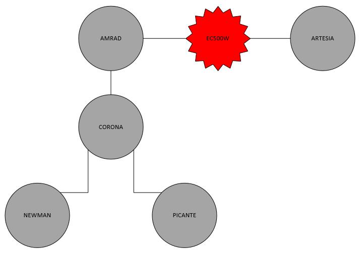
8 1.0 INTRODUCTION The Federal Energy Regulatory Commission (FERC) requires that an SIS be performed for generation facilities desiring to connect to any Transmission System. Here, the Interconnection Customer seeks to interconnect to the EPE Transmission System and to have its Generating Facility studied for ERIS. During the ERIS analysis, EC300W generation was reduced until all criteria violations were resolved. Steady State, Stability, and Short Circuit analysis were performed to determine the impact the EC300W ERIS request would have on the EPE Transmission System. Steady State and Stability analysis were performed using study cases for EPE planning year 2022 with both Peak and Off Peak loads. EPE has identified PNM as an Affected System for this SIS, so the Study Areas for the analyses were limited to WECC Areas 11 - EPE and 10 - PNM. The Study was performed in accordance with standards for WECC, NERC, and EPE. The EPE local reliability standards can be found in Section 4 of EPE s FERC Form No The Steady State and Stability analysis was performed using General Electric s (GE) Power System Load Flow (PSLF) software Version 19. Short Circuit analysis was performed using a 2022 study year while utilizing Aspen Oneliner software Version EC300W Project Description The EC300W Project was initially comprised of 500 MW of wind powered generation which was then reduced by the interconnection customer to 300 MW when the customer selected the ERIS option only for the Project. Therefore, this study report will treat this project as a 300 MW wind generating facility. The EC300W POI is a proposed new substation approximately six (6) mile away from Artesia 345 kv substation that will connect to the Artesia to Amrad 345 kv transmission line. The EC300W Project will be comprised of eleven (11) Vestas V110 turbines rated at 2.0 MW and seventy-eigth (78) Vestas V117 turbines rated at 3.6 MW each. The Vestas turbines are all to be installed at a terminal voltage of kv. This initial voltage would be stepped up to the 34.5 kv collector voltage for the Project. Two (2) main transformers will then step up the collector voltage to the 345 kv transmission voltage at the, to be constructed, substation, approximately six (6) mile west of the Artesia Substation, that will connect to the Artesia to Amrad 345 kv transmission line. Figure 1-1 shows the proposed POI for the EC300W Project. A Project one-line and model information are including in Appendix A. The EC300W Project will be comprised of eleven (11) Vestas V110 turbines rated at 2.0 MW and seventyeigth (78) Vestas V117 turbines rated at 3.6 MW each. The Vestas turbines are all to be installed at a terminal voltage of kv. This initial voltage would be stepped up to the 34.5 kv collector voltage for the Project. Two (2) main transformers will then step up the collector voltage to the 345 kv transmission voltage at the, to be constructed, substation, approximately six (6) mile west of the Artesia Substation, that will connect to the Artesia to Amrad 345 kv transmission line. Figure 1-1: EPE 345 kv Transmission System with EC300W POI 4
9 5
10 2.0 STUDY METHODOLOGY 2.1 Procedure, Assumptions & Criteria To test the EC30W Project for ERIS, Steady State and Stability Analysis was completed. A Short Circuit Duty Analysis and Steady State Power Factor Test were also completed to determine the EC300W impacts to the EPE system. The following assumptions are consistent for all study scenarios unless otherwise noted. The Study Areas for the ERIS analysis were limited to Western Electric Coordinating Council (WECC) Areas 11 - EPE and 10 PNM. This study assumed that all system expansion projects as planned by area utilities by the year under analysis are completed, and that any system improvements required by the interconnections senior to EC300W are implemented. This study did not analyze any transmission service from the interconnection point to any specific point on the grid for the interconnections senior to the EC300W Project. EC300W Project generation was assumed dispatched and delivered to/from EPE native load/gen in order to identify a maximum allowable ERIS output at the time the study was performed. To the extent the Interconnection Customer were to seek to transmit the Project generation to a particular delivery point on the EPE Transmission System, additional studies would have to be conducted as part of a point-to-point transmission service request. Transformer tap and phase-shifting transformer angle movement, as well as static var device switching, were allowed for the steady state pre-contingency analysis. All regulating equipment such as transformer controls and switched shunts were fixed at pre-contingency positions when the contingency analysis was performed. For post-contingency analysis Static var device switching was allowed, but all other regulation equipment was locked. All facility loadings at voltages 69 kv and greater were monitored within the El Paso control area. Pre-contingency and Post-contingency flows on lines and transformers were required to remain at or below the normal rating, while post-contingency flows on lines and transformers were required to remain at or below the emergency rating. Flows above 100% of an element s preproject or post-contingency rating were considered violations. All post-project voltage criteria violations that improve an existing pre-project violation were not considered an adverse impact to the system. The transmission performance criteria utilized for qualifying violations in the study area are shown in Table
11 Table 2-1: Transmission System Performance Criteria 1,2 VOLTAGE UTILITY ALIS (pu) - P0 N-1 (pu) - P1 ΔV (%) - P1 N-2 (pu) - P2-P7 ALIS (Normal) LINE LOADING (% Rating) N-1 - P1 (Emergency) TEP 138 kv TEP 345 kv TEP 500 kv TSGT PNM EPE Transmission Bus Voltages Subject to TSGT Comments BES Buses (Assumed 100 kv and Above Subject to PNM Comments) (115 kv) (345 kv buses) Transmission Bus Voltages Subject to TSGT Comments BES Buses (Assumed 100 kv and Above Subject to PNM Comments) 8 For Transmission Buses Subject to TSGT Comments 8 BES Buses (Assumed 100 kv and Above Subject to PNM Comments) (Greenlee 345 kv is 8%) Note: Only buses 100 kv or above shall be examined when applying TPL Powerflow Criteria Transmission Bus Voltages Subject to TSGT Comments BES Buses (Assumed 100 kv and Above Subject to PNM Comments) N-2 - P2-P7 (Emergency) 80/ (115 kv) For extreme events, per TPL-001-4, for the steady state and Stability Portion of the Planning Assessment, EPE will follow the requirements of Sections 3.5 and 4.5, respectively: if the analysis concludes there is Cascading caused by the occurrence of extreme event, an evaluation of possible actions designed to reduce the likelihood or mitigate the consequences and adverse impacts of the event(s) shall be conducted as the criteria or guidance for extreme events in Table 1 for extreme events of TPL P0 through P7 refers to the categories of contingencies identified in Table 1 of NERC Standard TPL-001-4, Transmission System Planning Performance Requirements. 3 Default criteria assumed following TPL-001-WECC-CRT3 in lieu of communicated criteria. 4 Exceptions may be granted for high side buses of Load-Tap-Changing (LTC) transformers that violate this criterion, if the corresponding low side buses are well within the criterion. 5 Planned station 6 69 KV voltage criteria as per EPE's latest FERC Form 715 filing. 7 Exceptions include: a) the minimum voltage level at radial 69kV and 115 kv radial buses and Amrad 115 kv can 0.90 pu. 8 Exceptions include: a) the voltage level at Artesia 345 kv can be up to 1.06 pu when the Eddy 345 kv Terminal is On, and 1.09 pu when the Eddy 345 kv Terminal is Off, and b) the voltage at the source side of the Arroyo phase shifter can be up to 1.08 pu. 9 The maximum voltage drop for Hidalgo 345 kv bus and separately the Luna 345 kv bus is 7% Taiban Mesa, Guadalupe 345 kv and Jicarilla, Clines Corners5 345 kv buses. 7
12 2.2 Development and Description of Power Flow Cases Two benchmark study cases, a 2022 Heavy Summer (Peak) and 2021/2022 Light Winter (Off Peak), were provided by EPE to develop the ERIS study cases. The Eddy County HVDC is on-line in the Peak case scenarios and off-line in the Off Peak cases. Afton Generation was modeled in service for Peak cases and out of service for Off Peak cases. The Arroyo Phase Shifter was modeled to provide MW N-S flow under Peak cases and MW N-S flow during the Off Peak cases. Table 2-2: Senior Queued Projects and Associated Network Upgrades Cluster Window Project Name Associated Network Upgrades Spring 2016 CA200S Add Corona 345 kv Substation Spring 2017 N200S None Table 2-2 lists the senior queued projects and associated network upgrades that were included in the SIS base cases. The pre-project base cases were developed by dispatching all senior queued generation to serve and offset EPE native load. The CA200S is a planned 200 MW solar installation with a POI at the (planned) Corona 345 kv Substation. The N200S Project is a 170 MW solar installation planned to interconnect at proposed substation on the Newman to Pipeline 115 kv transmission line. Post-project power flow base cases were then developed by dispatching the EC300W generation to serve and offset EPE native load. Automated change files to include the EC300W Project into a PSLF power flow model are provided in Appendix A. Table 2-3 shows the power flow generation dispatch in the bases cases that were developed and tested during the EC300W SIS. Please note that the EPE Local column does not include renewable generation dispatch. 2.3 Dynamic Stability Modeling Table 2-3: Case Dispatch HEAVY SUMMER CASES (MW) Study Case Scenarios EPE LOCAL IMPORT EC300W 2022HS_Pre (RIOGD_G8) HS_Post (MPS) LIGHT WINTER CASES (MW) Study Case Scenarios EPE LOCAL IMPORT EC300W 2022LW_Pre (RIOGD_G8) LW_Post (RIOGD_G8) Appendix A includes dynamic modeling data for the EC300W Project. The dynamic model consists of the WECC required sub-models: regc_a, reec_a, wtgq_a, wtgt_a, wtga_a, wtgp_a. The dynamic models include appropriate voltage and frequency parameters to comply with Low Voltage Ride Through criteria. 2.4 Dynamic Stability Modeling The steady state and stability contingency lists used for the EC300W SIS can be found in Appendix B. All contingencies were selected in accordance with NERC TPL criteria, and based on engineering judgement to represent a cross section of contingencies that would stress the EPE system. 8
13 3.0 STEADY STATE POWER FLOW ANALYSIS This section provides a high-level understanding of the impact EC300W would have on the loading of transmission lines and transformers in the Study Area. During the SIS Peak and Off Peak base cases were evaluated for thermally overloaded facilities under all applicable P0-P7 planning outages, as described in NERC TPL To determine Project impacts, the analysis was completed using the cases described in Table Normal Operating Condition Power Flow Evaluation Pre-project P0 Outage Power Flow Evaluation Power flow analysis was completed under system Normal (P0) conditions before the addition of the EC300W Project using both the Peak and Off Peak cases. Power flow analysis results showed no overloaded transmission facilities were present in the Study Area under Normal (P0) system conditions prior to the addition of the EC300W Project Post-project P0 Outage Power Flow Evaluation After addition of the EC300W Project, power flow study results showed potential overloads under P0 conditions. As shown in Table 3-1, the Artesia-Amrad 345 kv transmission line shows thermal overloads after the addition of the EC300W Project, prior to any system outage. Table 3-1: EC300W Impacts to Normal Equipment Loading Heavy Summer From Bus Name Monitored Element & Contingency kv To Bus Name kv MVA Rate Results (% of Normal Rating) 2022HS Pre 2022HS Post EC300W_POI 345 Amrad % 181% As described in Section 2.0, the proposed ERIS output of the EC300W Project will be limited to address the P0 violations in the table above. Detailed ERIS analysis results are presented in the section below. 3.2 ERIS Evaluation Thermal violations were observed during the SIS Steady State evaluation, therefore ERIS availability for EC300W is limited by the most constraining element. The EC300W POI is a proposed tap substation on the existing Amrad to Artesia 345 kv transmission line. That transmission line has been rated at 277 MW of total capacity. EPE owns 67% of capacity on the Amrad to Artesia 345 kv transmission line. At the time of the study, there was a maximum of 185 MW available for EC300W ERIS. ERIS interconnection service does not convey or imply a right to secure this 185 MW of transmission capability, or any other transmission capability. Transmission service from the POI to a requested Point of Delivery on the EPE transmission system would have to be applied for separately under the processes in the EPE Open Access Transmission Tariff. The MW outputs listed in Table 3-2 show the maximum ERIS available for the EC300W Project at the time of the ERIS SIS. Table 3-2: EC300W ERIS Dispatch Results Available ERIS Dispatch for EC300W EC300W ERIS Generation 185 MW 9
14 3.3 Emergency Operating Condition Power Flow Evaluation During the Study, all system normal (P0) violations were addressed prior to completion of the P1-P7 system outage analysis. Therefore, as stated in the section above, EC300W dispatch for the P1-P7 evaluation was 185 MW Pre-project P1-P7 Power Flow Evaluation Contingency power flow analysis was completed by testing the P1-P7 contingencies listed in Appendix B. Both the Peak and Off Peak cases were tested before the addition of the EC300W Project. Power flow analysis results showed no overloaded transmission facilities were present in the EPE area under P1-P7 conditions prior to the addition of the EC300W Project Post-project P1-P7 Power Flow Evaluation Contingency power flow analysis was completed on the Peak and Off Peak cases after the addition of the EC300W Project. Power flow analysis results continued to show no overloaded transmission facilities were present in the EPE area under P1-P7 conditions after the addition of the EC300W Project at 185 MW. 3.4 Power Flow Analysis Conclusion NERC planning event conditions P0-P7 were tested to evaluate the impacts of adding the EC300W Project to the EPE transmission system. Summary results presented in Section 3.0 show that the addition of the EC300W Project will create an overload violation on the EPE system. Table 3-2 shows the maximum ERIS availability for the EC300W Project is 185 MW. 10
15 4.0 STEADY STATE VOLTAGE ANALYSIS Bus voltages within the Study Area were evaluated under P0-P7 outage conditions with and without the EC300W Project generation in-service. The Performance Criteria shown in Table 2-1 were considered when analyzing bus voltages for violations. 4.1 Normal Operating Condition Voltage Evaluation The steady state voltage analysis for EC300W interconnection at the POI showed no voltage violations in the EPE area under P0 system conditions before or after the addition of EC300W generation. 4.2 Emergency Operating Condition Voltage Evaluation Contingency Voltage analysis was completed by testing the P1-P7 outages listed in Appendix B. The outages were tested on the Peak and Off Peak cases both before and after the addition of the EC300W Project. The steady state voltage analysis for EC300W interconnection at the POI showed no voltage violations in the EPE area under P1-P7 conditions before or after the addition of EC300W generation. 4.3 Delta Voltage Evaluation Bus voltages within the Study Area were evaluated under P1-P7 outage conditions to determine the change in voltage due to applicable design contingencies both with and without the EC300W Project generation in-service. The Performance Criteria shown in Table 2-1 were considered when analyzing bus voltages for violations. After testing all contingencies listed in Appendix B, results showed no bus voltages exceed the Delta Voltage threshold allowed by EPE Performance Criteria, 7% for 345 kv buses or 8% for the 115 kv buses. 4.4 Power Factor Test A power factor test was conducted on the EC300W Project to ensure it can maintain a 0.95 pu leading and lagging power factor at the requested POI when tested as a 300 MW installation. Results in However, results showed that the EC300W Project fails to meet the required lagging power factor, therefore an additional 100 MVAR SVC is required to support voltage at the POI. Please note that equipment required to meet voltage requirements at the POI are considered Generator Interconnection Costs, and Generator Interconnection Cost estimates have not been provided in this report. Table 4-1 show that the EC300W Project is designed with the capability to absorb vars past a 0.95 pu leading power factor. However, results showed that the EC300W Project fails to meet the required lagging power factor, therefore an additional 100 MVAR SVC is required to support voltage at the POI. Please note that equipment required to meet voltage requirements at the POI are considered Generator Interconnection Costs, and Generator Interconnection Cost estimates have not been provided in this report. PF Test Location Table 4-1: Power Factor Test Results Power Factor Test Results EC300W Power Factor (pu) EC300W MW EC300W Mvar Additional POI Reactive (Mvar) EC300W MPT 345 kv Bus Leading N/A EC300W MPT 345 kv Bus Lagging N/A EC300W MPT 345 kv Bus Lagging
16 4.5 Steady State Voltage Analysis Conclusions NERC planning event conditions P0-P7 were tested to evaluate the impacts of adding the EC300W Project. The steady state voltage analysis did not show any voltage violations before or after the addition of the EC300W Project. However, Power Factor Test showed that the EC300W Project is required to include up to 100 MVAR of additional reactive support at the POI to maintain the required leading and lagging 0.95 pu power factor. 12
17 5.0 SHORT CIRCUIT ANALYSIS A short circuit analysis was performed to determine if adding of the EC300W Project to the EPE transmission system would cause any existing transmission circuit breakers to exceed their interrupting capability ratings. 5.1 Short Circuit Analysis Procedure Three phase, two phase, and single-phase-to-ground faults were simulated at all buses in the EPE and PNM system. The ASPEN One Liner and Batch Short Circuit Module were used to perform the short circuit analysis. The short circuit fault analyses were performed with the following settings: Transmission line G+jB ignored. Shunts with positive sequence impedance ignored. Transformer line shunts ignored The pre-fault voltage was calculated using a Flat bus voltage of 1.05 per unit. Fault currents within the EPE System where analyzed before and after the addition of the EC300W Project. Buses that showed an increase of 100 amps or more were reported. These scenarios were then compared against the smallest breaker interruption ratings at each substation to determine whether any breaker was over dutied under pre-project or post-project conditions. Project 5.2 Short Circuit Analysis Modeling The Short Circuit modeling data was provided by each Project Developer. The generator and collector system impedance data used to model the EC300W Project is listed below in Table 5-1. To determine project impacts the analysis was performed both with and without the EC300W Project in- service. Unit ID Pmax MW Pmin MW Table 5-1: EC300W Project Short Circuit Modeling Data Generation Unit Generation Step-Up Transformer Main Transformer Qmax Mvar Qmin Mvar Z Sub-Tran Rating MVA Voltage kv Z Pos Seq Rating MVA Voltage (kv) Z Pos Seq EC300W j / j /34.5/ j0.089 EC300W j / j /34.5/ j Short Circuit Analysis Results and Conclusion Results of the short circuit study showed that the addition of the EC300W Project did not cause any existing EPE circuit breakers to exceed their interrupting capability. 13
18 6.0 STABILITY ANALYSIS A Transient Stability analysis was performed under Peak and Off Peak load conditions to determine what impact the EC300W Project will have on the EPE system stability. This analysis evaluated the performance of the system for selected faults. The purpose of this analysis is to ensure the system has adequate damping after a fault/trip event. Simulations were conducted using the PSLF power flow and dynamic simulation software, General Electric, Inc. PSLF load flow software package, Version 19 and the associated DYTools module. Dynamic stability simulations were conducted for Peak and Off Peak load conditions on the Post-project study cases discussed in Section Stability Study Case Development and EC300W Stability Modeling Dynamic stability simulations were conducted for Peak and Off Peak load conditions on the Post-project study cases discussed in Section 2.2. The EC300W stability control model provided was added to the EPE provided dynamic database for this part of the study. The EC300W dynamic model is provided included in Appendix A and consists of the WECC required sub-models: regc_a, reec_a, wtgq_a, wtgt_a, wtga_a, wtgp_a. 6.2 ERIS Stability Analysis & Results The Stability Contingencies List verified during this analysis is included in Appendix B. Output plots from runs with EC300W at maximum output are provided to show dynamic model performance. The simulation results are provided in Appendix C for the Peak and Off Peak study cases. Results show that both the EC300W Project generators and the EPE transmission system remained stable and positively damped for all simulations tested. Stability Run Summary Results for all tested simulations are also provided in Appendix C. 6.3 Low Voltage Ride Through Test Low Voltage Ride Through (LVRT) faults were completed by testing EC300W generator response to a 9 cycle 3-phase and a 18 cycle single-phase fault at the high side (or 345 kv bus) of the Project s MPT. Results show the Project remains online and stable during each of the LVRT fault simulations. 6.4 Stability Analysis Conclusion Results show that the EC300W Project and the EPE system remained stable and positively damped for all simulations tested. 14
19 7.0 COST ESTIMATES, COST ALLOCATION, & PROJECT SCHEDULE Good faith cost estimates for interconnection of the EC300W Project is presented below in 2018 dollars with an accuracy of +/-50% (no escalation applied). The cost estimates are based upon costs for previously performed similar construction. These costs include estimated applicable labor and overheads associated with the engineering, design, and construction of these new EPE facilities. It does not include costs associated with securing land rights, rights-of-way, permits, environmental and/or archeological clearances. Per EPE requirements, a Phase Measurement Unit (PMU) is included at the POI. 7.1 EC300W Preliminary Cost Estimates Figure 7-1 is the conceptual one-line that was used to develop the cost estimates for EC300W interconnection at the requested POI. A breakdown of major cost items is shown in Table 7-1 and Table 7-2. The estimates below did not include the Generator Interconnection Costs for any other Interconnection Customer owned equipment or associated design and engineering except for the POI. To that end, please note that in order for EC300W to meet EPE voltage criteria at the POI, a 100 MVAR SVC, is required near the POI Substation in order for the output of the Generating Facility to be eligible to enter the POI.. Figure 7-1: EC300W Conceptual One-line 15
20 EC300W POI Estimate Notes and Assumptions: 1) Relay upgrades or settings at adjacent substations are not included in the estimates. 2) Prefer (4) sets of BCTs, with relay class C800 and 0.3% metering accuracy for each circuit breaker. 3) Substation yard size considered is 400 x ) Ground Grid will be required at the substation. 5) Includes fencing and gates 6) New Control House 7) Four Lightning masts, for lightning protection will be required. 8) Site grading and ground preparation will be required. 9) Yard lighting fixtures will be required. 10) Cable trenches and conduit system included. 11) Land cost is not included in the estimate. 12) Access road provision is not included. 13) Permitting activities are not included. Element EC300W (345 kv) Substation and POI Table 7-1: Network Upgrades. Interconnection Substation Costs for EC300W Description The new EC300W substation (345 kv) will require new equipment, as listed below. Qty. (1) Replace existing static on Amrad to Artesia 345 kv line Cost Est. Millions $
21 Element Description Two (2) 345kV 3000A, Gas Circuit Breaker. Two (2) 345kV Dead-end structures. (1-lot) Steel structures for 345kV Bus Support, Surge Arresters, 345kV Switches, and PT s. Two (2) 345kV 3000A, GOAB, disconnect switches. Six (6) CVTs, (2-sets), and structures. Six (6) Lightning Arresters (2-sets). Four (4) Shielding poles and foundations. Ninety (90) 345kV insulators for bus works. (1- lot) Transmission line relaying, SCADA, communication. (1- lot) Ground Grid system, including ground rods and Grounding conductors. Four (4) panels with relays, control modules and wiring. Transmission line relaying, SCADA, communication. (1-lot) Control cables and other cables. (1- lot) Foundations for 345 kv GCB, Switches, CVTs, Surge Arresters, and Metering Unit Dead-end structure, and lightning masts. (1- lot) Cable trench, Raceways, and Conduits (1- lot) Site prep, grading and roadways Estimated Time Frame for Engineering, Procurement, Construction, and Commissioning Cost Est. Millions 48 Months 17
22 Element EC300W 345 kv Substation Table 7-2: EPE Interconnection Facilities Costs for EC300W Description EPE Interconnection Facilities located at new EC300W substation One 345 kv 3000 A disconnect switch w/ grounding One 345 kv Dead-end Structure One (1) 345kV 3000A, Gas Circuit Breakers One set of three (3) CVTs and Structures Three Lightning arresters and Structures One Set of 345 kv 3-Phase Metering Units and structures Relaying, communication, and testing Estimated Time Frame for Engineering, Procurement, Construction, and Commissioning Cost Est. Millions $ Months 7.2 EC300W ERIS Interconnection Schedule A preliminary Project Schedule for the EC300W Project is provided as Appendix D. The Project Schedule includes a breakdown of the estimated time for Engineering, Procurement, Construction and Commissioning. The estimated time frame for Engineering, through Commissioning, for the requested POI is approximately 48 months. The timeframes do not account for land rights acquisition and permitting, and any environmental and archeological studies necessary to design, and construct the facilities. 18
23 8.0 DISCLAIMER If any of the project data used in this study varies significantly from the actual data of the installed generation equipment, the results from this study will need to be verified with the actual data at the Project Interconnection Customer's expense. Additionally, any change in the generation in EPE s Interconnection Queue that is senior to the EC300W Project may require a re-evaluation of this Study. 19
24 9.0 CONCLUSIONS The objective of this SIS was to evaluate potential impacts to the EPE transmission system caused by the requested addition of the EC300W generator interconnection project. The proposed project has requested ERIS to interconnect 300 MW of wind turbine generation at a, to be constructed, tap substation on the Artesia to Amrad 345 kv Substation, the requested POI. Short Circuit, Steady State, and Stability contingency analysis were performed using all applicable standards from EPE, WECC, and NERC. To resolve any observed criteria violations, EC300W generation was reduced until all violations were resolved. Steady State analysis was completed by applying applicable NERC Transmission Planning Performance Requirements (TPL) planning scenarios P0-P7. Steady state thermal analysis results showed that the addition of the EC300W Project will create an overload violation on the EPE system. To resolve all criteria violations, the ERIS availability for the EC300W Project is 185 MW at the time of the study. Steady state voltage analysis results did not show any criteria violations under NERC TPL planning scenario P0-P7. However, Power Factor Test results showed that the EC300W Project is required to include up to 100 MVAR of additional dynamic reactive support at the POI, on the customer side, to maintain the required leading and lagging 0.95 pu power factor. Please note that it is the responsibility of the EC300W interconnection customer to ensure the Project has sufficient var capabilities to maintain the voltage schedule required by EPE. For EC300W interconnection at the requested POI, the estimated total cost for the required upgrades is $18.98 Million. This breaks down to $1.05 Million for the EPE Interconnection Costs at the POI and $17.93 Million for the Interconnection Substation Upgrade Costs. The estimated time frame for Engineering, Procurement, and Construction for interconnection at the requested POI for EC300W is approximately 48 months upon notice to proceed with construction from the Interconnection Customer. 20
25 Appendix A Project Modeling Information 21
26 Appendix B Contingency Lists 22
27 Appendix C Stability Analysis Results 23
28 Appendix D Preliminary Interconnection Schedule 24
SYSTEM IMPACT RESTUDY H252W ERIS REPORT. El Paso Electric Company
 SYSTEM IMPACT RESTUDY H252W ERIS REPORT Prepared for: El Paso Electric Company Prepared by: Engineers, LLC 1526 Cole Boulevard Building 3, Suite 150 Lakewood, CO 80401 (303) 395-4018 FOREWORD This report
SYSTEM IMPACT STUDY REPORT LA450S GENERATION STUDY. El Paso Electric Company
 SYSTEM IMPACT STUDY REPORT LA450S GENERATION STUDY Prepared for: El Paso Electric Company Prepared by: Engineers, LLC 1526 Cole Boulevard Building 3, Suite 150 Lakewood, CO 80401 (303) 395-4018 FOREWORD
El Paso Electric Company
 Feasibility Study XXXXXX Solar Generation Prepared for El Paso Electric Company Prepared by TRC Engineers, LLC 249 Eastern Avenues Augusta, ME 04330 (207) 621-7000 Project Number: 202327 May 2013 FOREWORD
ENERGY RESOURCE INTERCONNECTION SERVICE STUDY DRAFT REPORT
 ENERGY RESOURCE INTERCONNECTION SERVICE STUDY DRAFT REPORT ART320W 320 MW Wind Powered Project Prepared for: El Paso Electric Company Prepared by: TRC Engineers, LLC 249 Western Avenue Augusta, ME 04330
EL PASO ELECTRIC COMPANY (EPE) FACILITIES STUDY FOR PROPOSED HVDC TERMINAL INTERCONNECTION AT NEW ARTESIA 345 KV BUS
 FACILITIES STUDY FOR PROPOSED HVDC TERMINAL INTERCONNECTION AT NEW ARTESIA 345 KV BUS") EL PASO ELECTRIC COMPANY (EPE) FACILITIES STUDY FOR PROPOSED HVDC TERMINAL INTERCONNECTION AT NEW ARTESIA 345 KV BUS El Paso Electric Company System Operations Department System Planning Section May 2004
EL PASO ELECTRIC COMPANY (EPE) FACILITIES STUDY FOR PROPOSED HVDC TERMINAL INTERCONNECTION AT NEW ARTESIA 345 KV BUS El Paso Electric Company System Operations Department System Planning Section May 2004
Interconnection System Impact Study Report Request # GI
 Executive Summary Interconnection System Impact Study Report Request # GI-2008-23 34 MW Solar Generation Ranch at Hartsel, Colorado Public Service Company of Colorado Transmission Planning August 19, 2010
EL PASO ELECTRIC COMPANY (EPE) GENERATOR INTERCONNECTION SYSTEM IMPACT STUDY FOR PROPOSED XXXXXXXXXXXXXXXXXX GENERATION ON THE AMRAD-ARTESIA 345 KV
 GENERATOR INTERCONNECTION SYSTEM IMPACT STUDY FOR PROPOSED XXXXXXXXXXXXXXXXXX GENERATION ON THE AMRAD-ARTESIA 345 KV") EL PASO ELECTRIC COMPANY (EPE) GENERATOR INTERCONNECTION SYSTEM IMPACT STUDY FOR PROPOSED XXXXXXXXXXXXXXXXXX GENERATION ON THE AMRAD-ARTESIA 345 KV LINE El Paso Electric Company System Planning Department
EL PASO ELECTRIC COMPANY (EPE) GENERATOR INTERCONNECTION SYSTEM IMPACT STUDY FOR PROPOSED XXXXXXXXXXXXXXXXXX GENERATION ON THE AMRAD-ARTESIA 345 KV LINE El Paso Electric Company System Planning Department
Interconnection Feasibility Study Report Request # GI Draft Report 600 MW Wind Generating Facility Missile Site 230 kv Substation, Colorado
 Executive Summary Interconnection Feasibility Study Report Request # GI-2016-6 Draft Report 600 MW Wind Generating Facility Missile Site 230 kv Substation, Colorado Public Service Company of Colorado Transmission
XXXXXXXXXXXXXXXX Transmission Interconnection Feasibility Study
 XXXXXXXXXXXXXXXX Transmission Interconnection Feasibility Study System Operations Department System Planning Section March 2002 Table of Contents: 1.0 EXECUTIVE SUMMARY 4 2.0 COST ESTIMATES 8 2.1 Cost
Feasibility Study Report
 Generator Interconnection Request Feasibility Study Report For: Customer --- Service Location: Rutherford County Total Output: 79.2 MW Commercial Operation Date: 9/1/2014 In-Service Date (if given): 9/1/2014
Generation Interconnection Feasibility Study For XXXXXXXXXXXXXXXXXXXXXX MW generator at new Western Refinary Substation
 Generation Interconnection Feasibility Study For XXXXXXXXXXXXXXXXXXXXXX 131-250 MW generator at new Western Refinary Substation System Planning Section April, 2005 TABLE OF CONTENT 1 EXECUTIVE SUMMARY
Interconnection System Impact Study Final Report February 19, 2018
 Interconnection System Impact Study Final Report February 19, 2018 Generator Interconnection Request No. TI-17-0225 248.4 MW (Alternate Project Output of 217.35 MW) Wind Energy Generating Facility In Goshen
Project #148. Generation Interconnection System Impact Study Report
 Project #148 Generation Interconnection System Impact Study Report June 05, 2012 Electric Transmission Planning Table of Contents Table of Contents... 2 Executive Summary... 3 Energy Resource Interconnection
El PASO ELECTRIC COMPANY 2014 BULK ELECTRIC SYSTEM TRANSMISSION ASSESSMENT FOR YEARS
 El Paso Electric Company El PASO ELECTRIC COMPANY 2014 BULK ELECTRIC SYSTEM TRANSMISSION ASSESSMENT FOR YEARS 2015 2024 A Review on System Performance Following Extreme Bulk Electric System Events of the
EL PASO ELECTRIC COMPANY SHORT CIRCUIT ANALYSIS FOR XXX S PROPOSED GENERATION INTERCONNECTION
 EL PASO ELECTRIC COMPANY SHORT CIRCUIT ANALYSIS FOR XXX S PROPOSED GENERATION INTERCONNECTION El Paso Electric Company System Operations Department System Planning Section August 2006 I. INTRODUCTION The
System Impact Study Report
 Report For: NTE Carolinas II, LLC ( Customer ) Queue #: 42432-01 Service Location: Rockingham County, NC Total Output: 477 MW (summer) / 540 MW (winter) Commercial Operation Date: 12/1/2020 42432-01 SIS
March 2017 to June 2017 Preliminary Interconnection Cluster Window System Impact Study 49.9 MW IA-PNM May 2018
 March 2017 to June 2017 Preliminary Interconnection Cluster Window System Impact Study 49.9 MW IA-PNM-2017-11 May 2018 Prepared by: Public Service Company of New Mexico Foreword This report is prepared
PJM Generator Interconnection Request Queue #R60 Robison Park-Convoy 345kV Impact Study September 2008
 PJM enerator Interconnection Request Queue #R60 Robison Park-Convoy 345kV Impact Study 504744 September 2008 PJM Interconnection 2008. All rights reserved R60 Robison Park-Convoy 345kV Impact Study eneral
100 MW Wind Generation Project
 A subsidiary of Pinnacle West Capital Corporation 100 MW Wind Generation Project CUSTOMER FINAL Feasibility Study Results By Transmission Planning, APS December 21, 2007 Executive Summary This Feasibility
Interconnection Feasibility Study Report GIP-226-FEAS-R3
 Interconnection Feasibility Study Report GIP-226-FEAS-R3 System Interconnection Request #226 70 MW Wind Generating Facility Kings County (L-6013) 2010 07 21 Control Centre Operations Nova Scotia Power
Generator Interconnection System Impact Study For
 Generator Interconnection System Impact Study For Prepared for: January 15, 2015 Prepared by: SCE&G Transmission Planning Table of Contents General Discussion... Page 3 I. Generator Interconnection Specifications...
Elbert County 500 MW Generation Addition Interconnection Feasibility Study Report OASIS POSTING # GI
 Executive Summary Elbert County 500 MW Generation Addition Interconnection Feasibility Study Report OASIS POSTING # GI-2003-2 Xcel Energy Transmission Planning January 2004 This Interconnection Feasibility
XXXXXXXXXXXXXXXXXXXXXXXXX TRANSMISSION/GENERATION FEASIBILITY STUDY FATAL FLAW AND FEASIBILITY ANALYSIS
 XXXXXXXXXXXXXXXXXXXXXXXXX TRANSMISSION/GENERATION FEASIBILITY STUDY FATAL FLAW AND FEASIBILITY ANALYSIS System Operations Department System Planning Section June 2001 TABLE OF CONTENTS 1.0 Executive Summary...Page
ABB Inc. Public Service Company of New Mexico Broadview Full Buildout Affected PSLF Study
 ABB Inc. Public Service Company of New Mexico Broadview Full Buildout Affected PSLF Study Final Report ABB Power Systems Consulting June 27, 2016 LEGAL NOTICE This document, prepared by ABB Inc, is an
Project #94. Generation Interconnection System Impact Study Report Revision
 Project #94 Generation Interconnection System Impact Study Report Revision October 2, 2009 Electric Transmission Planning Table of Contents Table of Contents...2 Executive Summary...3 Energy Resource Interconnection
CUSTOMER/ TWIN ARROWS PROJECT
 A subsidiary of Pinnacle West Capital Corporation CUSTOMER/ TWIN ARROWS PROJECT V1 Facility Study Report APS Contract 52149 Prepared by: Arizona Public Service Company Transmission & Distribution Asset
MILLIGAN SOLAR PROJECT
 February 16, 2009 Page 1 of 18 A subsidiary of Pinnacle West Capital Corporation MILLIGAN SOLAR PROJECT FINAL Feasibility Study Report APS Contract 52115 Prepared by: Arizona Public Service Company Transmission
SPS Planning Criteria and Study Methodology
 SPS Planning Criteria and Study Methodology SPS subscribes to the Southwest Power Pool ("SPP") Reliability Criteria, which incorporates compliance with the appropriate North American Electric Reliability
AMERICAN ELECTRIC POWER 2017 FILING FERC FORM 715 ANNUAL TRANSMISSION PLANNING AND EVALUATION REPORT PART 4 TRANSMISSION PLANNING RELIABILITY CRITERIA
 AMERICAN ELECTRIC POWER 2017 FILING FERC FORM 715 ANNUAL TRANSMISSION PLANNING AND EVALUATION REPORT PART 4 TRANSMISSION PLANNING RELIABILITY CRITERIA AEP Texas (comprised of its Central and North Divisions
PID 274 Feasibility Study Report 13.7 MW Distribution Inter-Connection Buras Substation
 PID 274 Feasibility Study Report 13.7 MW Distribution Inter-Connection Buras Substation Prepared by: Entergy Services, Inc. T & D Planning L-ENT-17A 639 Loyola Avenue New Orleans, LA 70113 Rev Issue Date
Interconnection Feasibility Study Report GIP-222-FEAS-R3
 Interconnection Feasibility Study Report GIP-222-FEAS-R3 System Interconnection Request #222 48 MW Steam Generating Facility Pictou County (53N) 2010 07 30 Control Centre Operations Nova Scotia Power Inc.
Interconnection Feasibility Study Report GIP-084-FEAS-R2
 Interconnection Feasibility Study Report GIP-084-FEAS-R2 System Interconnection Request #84 50 MW Wind Generating Facility Pictou County (L-7004) August 17, 2007 Control Centre Operations Nova Scotia Power
Verde Transmission, LLC. Verde Project. System Impact Study Report
 Verde Transmission, LLC Verde Project System Impact Study Report March 2017 Prepared by: Public Service Company of New Mexico Foreword This report was prepared for Verde Transmission, LLC by the PNM Transmission/
Interconnection Feasibility Study Report GIP-157-FEAS-R2
 Interconnection Feasibility Study Report GIP-157-FEAS-R2 System Interconnection Request #157 100.5 MW Wind Generating Facility Guysborough County (L-6515) 2009 09 14 Control Centre Operations Nova Scotia
Generator Interconnection Facilities Study For SCE&G Two Combustion Turbine Generators at Hagood
 Generator Interconnection Facilities Study For SCE&G Two Combustion Turbine Generators at Hagood Prepared for: SCE&G Fossil/Hydro June 30, 2008 Prepared by: SCE&G Transmission Planning Table of Contents
Feasibility Study for the Q MW Solar Project
 Feasibility Study for the Q171 74.5 MW Solar Project August 2018 Bulk Transmission Planning, Florida i This document and any attachments hereto ( document ) is made available by Duke Energy Florida, LLC
THE NECESSITY OF THE 500 KV SYSTEM IN NWE S TRANSMISSION SYSTEM TO MAINTAIN RELIABLE SERVICE TO MONTANA CUSTOMERS
 THE NECESSITY OF THE 500 KV SYSTEM IN NWE S TRANSMISSION SYSTEM TO MAINTAIN RELIABLE SERVICE TO MONTANA CUSTOMERS 2/27/2018 ELECTRIC TRANSMISSION PLANNING Table of Contents Table of Contents... 2 Executive
Interconnection Feasibility Study Report GIP-IR373-FEAS-R1
 Interconnection Feasibility Study Report GIP-IR373-FEAS-R1 Generator Interconnection Request 373 109.5 MW Wind Generating Facility South Canoe Lake, NS Mar. 2, 2012 Control Centre Operations Nova Scotia
Interconnection Feasibility Study Report GIP-023-FEAS-R1. Generator Interconnection Request # MW Wind Generating Facility Inverness (L6549), NS
, NS") Interconnection Feasibility Study Report GIP-023-FEAS-R1 Generator Interconnection Request # 23 100 MW Wind Generating Facility Inverness (L6549), NS February 16, 2006 Control Centre Operations Nova Scotia
Interconnection Feasibility Study Report GIP-023-FEAS-R1 Generator Interconnection Request # 23 100 MW Wind Generating Facility Inverness (L6549), NS February 16, 2006 Control Centre Operations Nova Scotia
Q95 Vicksburg 69kV. System Impact Study. APS Contract No Arizona Public Service Company Transmission Planning.
 A subsidiary of Pinnacle West Capital Corporation Q95 Vicksburg 69kV System Impact Study APS Contract No. 52246 By Arizona Public Service Company Transmission Planning December 1, 2010 Version 2.6 Final
Feasibility Study Report
 Report For: Fresh Air Energy II, LLC ( Customer ) Queue #: Service Location: Chester County, SC Total Output Requested By Customer: 74.5 MW Commercial Operation Date Requested By Customer: 1/7/2019 Feasibility
300 MW SOLAR PHOTOVOLTAIC PLANT, GENERATOR INTERCONNECTION FEASIBILITY STUDY
 300 MW SOLAR PHOTOVOLTAIC PLANT, GENERATOR INTERCONNECTION FEASIBILITY STUDY El Paso Electric Company System Planning August 2006 TABLE OF CONTENTS 1.0 EXECUTIVE SUMMARY...Page 1 2.0 PURPOSE...Page 7 3.0
PUD ELECTRIC SYSTEM INTERCONNECTION
 APPENDIX A PROCEDURES & REQUIREMENTS for OKANOGAN PUD ELECTRIC SYSTEM INTERCONNECTION Version 4.0 December 2011 Version 4.0 12/28/2011 Page 1 of 15 TABLE OF CONTENTS DEFINITIONS 1.0 Introduction 2.0 Procedures
Wheeler Ridge Junction Substation Project Description and Functional Specifications for Competitive Solicitation
 Wheeler Ridge Junction Substation Project Description and Functional Specifications for Competitive Solicitation 1. Description In the 2013-2014 Transmission Planning Cycle, the ISO approved the construction
Midway/Monument Area TTC Study
 Midway/Monument Area TTC Study (includes the following lines: Midway Geesen 115 kv, Geesen Falcon 115 kv, Falcon Fuller 115 kv, Fuller Black Squirrel 115 kv, and Black Squirrel Monument 115 kv) Johnny
XXXXXXXXXXXXXXXXXXXX GENERATION INTERCONNECTION FACILITIES STUDY SHORT CIRCUIT ANALYSIS FOR PROPOSED GENERATION AT NEWMAN 115 kv BUS
 XXXXXXXXXXXXXXXXXXXX GENERATION INTERCONNECTION FACILITIES STUDY SHORT CIRCUIT ANALYSIS FOR PROPOSED GENERATION AT NEWMAN 115 kv BUS El Paso Electric Company System Operations Department System Planning
PJM Generator Interconnection R81 Emilie (Fords Mill) MW Impact Study Re-Study
 MW Impact Study Re-Study") PJM Generator Interconnection R81 Emilie (Fords Mill) 100.9 MW Impact Study Re-Study August 2008 DMS # 498781 General Queue R81 Emilie (Fords Mills) is a Fairless Energy, LLC request to obtain an additional
PJM Generator Interconnection R81 Emilie (Fords Mill) 100.9 MW Impact Study Re-Study August 2008 DMS # 498781 General Queue R81 Emilie (Fords Mills) is a Fairless Energy, LLC request to obtain an additional
Service Requested 150 MW, Firm. Table ES.1: Summary Details for TSR #
 Executive Summary Firm point to point transmission service has been requested by Transmission Service Request (TSR) #75669514, under the SaskPower Open Access Transmission Tariff (OATT). The TSR consists
Feasibility Study Report
 Report For: Orion Renewable Resources LLC ( Customer ) Queue #: Service Location: Rockingham County, NC Total Output Requested By Customer: 100 MW Commercial Operation Date Requested By Customer: 11/1/2019
XXXXXXXXXXXXXXXXXXXXXXXXXXXX TRANSMISSION/GENERATION FEASIBILITY STUDY FATAL FLAW AND FEASIBILITY ANALYSIS
 XXXXXXXXXXXXXXXXXXXXXXXXXXXX TRANSMISSION/GENERATION FEASIBILITY STUDY FATAL FLAW AND FEASIBILITY ANALYSIS El Paso Electric Company System Operations Department System Planning Section September 2001 TABLE
Feasibility Study for the Q MW Solar Project
 Feasibility Study for the Q174 74.5 MW Solar Project August 2018 Bulk Transmission Planning, Florida i This document and any attachments hereto ( document ) is made available by Duke Energy Florida, LLC
New Mexico Transmission Expansion Concepts For Wind Resources
 New Mexico Transmission Expansion Concepts For Wind Resources May 2008 Update Electric Services Transmission Operations FOREWORD This document contains PNM s latest concepts for expanding the transmission
Transmission Coordination and Planning Committee 2014 Q4 Stakeholder Meeting. December 18, 2014
 Transmission Coordination and Planning Committee 2014 Q4 Stakeholder Meeting December 18, 2014 Agenda 1. Introductions 2. TCPC Policies 3. BHCE Planning Department Update 4. 2014 LTP Study Results 5. Stakeholder
XXXXXXXXXXXXXX 99 MW WIND PARK GENERATOR INTERCONNECTION FEASIBILITY STUDY. September 2008 Prepared by: EL PASO ELECTRIC COMPANY
 XXXXXXXXXXXXXX 99 MW WIND PARK GENERATOR INTERCONNECTION FEASIBILITY STUDY September 2008 Prepared by: EL PASO ELECTRIC COMPANY Foreword This report was prepared for XXXXXXXXXXXXX (XXX) of XXXXXXXX by
XXXXXXXXXXXXXXXXXXXXXXXXXXXXXXX TRANSMISSION/GENERATION FEASIBILITY STUDY SHORT CIRCUIT ANALYSIS
 XXXXXXXXXXXXXXXXXXXXXXXXXXXXXXX TRANSMISSION/GENERATION FEASIBILITY STUDY SHORT CIRCUIT ANALYSIS El Paso Electric Company System Operations Department System Planning Section September 2001 Short Circuit
XXXXXXXXXXXXXXXXXXXXXXXXXXXXXXXXXXXXXX TRANSMISSION AND FACILITIES STUDY. Short Circuit Analysis
 XXXXXXXXXXXXXXXXXXXXXXXXXXXXXXXXXXXXXX TRANSMISSION AND FACILITIES STUDY Short Circuit Analysis System Operations Department System Planning Section March 2001 I. Introduction XXXXXXXXXXXXXXXXXXXXXXXXXXXXXXXXX
DUKE ENERGY PROGRESS TRANSMISSION SYSTEM PLANNING SUMMARY
 DUKE ENERGY PROGRESS TRANSMISSION SYSTEM PLANNING SUMMARY Transmission Department Transmission Planning Duke Energy Progress TABLE OF CONTENTS I. SCOPE 3 II. TRANSMISSION PLANNING OBJECTIVES 3 III. TRANSMISSION
Transmission Competitive Solicitation Questions Log Question / Answer Matrix Harry Allen to Eldorado 2015
 No. Comment Submitted ISO Response Date Q&A Posted 1 Will the ISO consider proposals that are not within the impedance range specified? Yes. However, the benefits estimated and studies performed by the
High Lonesome Mesa 100 MW Wind Generation Project (OASIS #IA-PNM ) Interconnection Facility Study. Final Report November 2, 2007
 Interconnection Facility Study. Final Report November 2, 2007") High Lonesome Mesa 100 MW Wind Generation Project (OASIS #IA-PNM-2006-02) Interconnection Facility Study Final Report November 2, 2007 Prepared by: Public Service Company of New Mexico Electric Services
High Lonesome Mesa 100 MW Wind Generation Project (OASIS #IA-PNM-2006-02) Interconnection Facility Study Final Report November 2, 2007 Prepared by: Public Service Company of New Mexico Electric Services
Consulting Agreement Study. Completed for Transmission Customer
 Completed for Transmission Customer Proposed Resource & Transmission Carbon County, MT & 230 kv Transmission in North Wyoming August 2016 Table of Contents 1.0 Description... 1 2.0 Overall Assumptions...
Generation Interconnection Facilities Study For
 Generation Interconnection Facilities Study For Prepared for: Prepared by: SCE&G Transmission Planning May 27, 2015 TABLE OF CONTENTS General Discussion... Page 3 Generator Interconnection Specifications...
Short Circuit Analysis with New Generation Proposed by XXXXXXXXXXXXXXXXXXXXXX Pursuant to a Transmission and Facilities Study
 Short Circuit Analysis with New Generation Proposed by XXXXXXXXXXXXXXXXXXXXXX Pursuant to a Transmission and Facilities Study Study Performed by El Paso Electric Company System Planning Section - 1 I.
Q217 Generator Interconnection Project
 Q217 Generator Interconnection System Impact Study APS Contract No. 52588 By Arizona Public Service Company Transmission Planning November 25, 2013 Version 2.0 Prepared by Utility System Efficiencies,
ABB POWER SYSTEMS CONSULTING
 ABB POWER SYSTEMS CONSULTING DOMINION VIRGINIA POWER Offshore Wind Interconnection Study 2011-E7406-1 R1 Summary Report Prepared for: DOMINION VIRGINIA POWER Report No.: 2011-E7406-1 R1 Date: 29 February
Final Draft Report. Assessment Summary. Hydro One Networks Inc. Longlac TS: Refurbish 115/44 kv, 25/33/ General Description
 Final Draft Report Assessment Summary Hydro One Networks Inc. : Refurbish 115/44 kv, 25/33/42 MVA DESN Station CAA ID Number: 2007-EX360 1.0 General Description Hydro One is proposing to replace the existing
Georgia Transmission Corporation Georgia Systems Operations Corporation
 Georgia Transmission Corporation Georgia Systems Operations Corporation Reactive Power Requirements for Generating Facilities Interconnecting to the Georgia Integrated Transmission System with Georgia
120 MW SOLAR-THERMAL PLANT GENERATOR INTERCONNECTION FEASIBILITY STUDY. May 2008 Prepared by: EL PASO ELECTRIC COMPANY
 . 120 MW SOLAR-THERMAL PLANT GENERATOR INTERCONNECTION May 2008 Prepared by: EL PASO ELECTRIC COMPANY Foreword This report was prepared for XXXXXXXXXXXXXXXXXXX by System Planning at El Paso Electric Company.
Interconnection Feasibility Study Report GIP-369-FEAS-R1
 Interconnection Feasibility Study Report GIP-369-FEAS-R1 System Interconnection Request #369 50 MW Wind Generating Facility Cumberland County (L-6513) 2012-02-09 Control Centre Operations Nova Scotia Power
Burlington Lamar 345/230 kv Impact and 2013 Post TPL Assessment Study
 Burlington Lamar 345/230 kv Impact and 2013 Post TPL Assessment Study Vince Leung May 1, 2014 Reviewed by: Chris Pink (edited July 8, 2014) Table of Contents Page Background... 4 Objectives... 5 Study
Emera Maine Representative: Jeffrey Fenn, P.E., SGC Engineering LLC
 OCTOBER 22, 2014 Emera Maine s Local System Plan Bangor Hydro District Needs Assessment/Potential Solutions Local Planning Advisory Committee Meeting E M i R t ti Emera Maine Representative: Jeffrey Fenn,
TRANSMISSION PLANNING CRITERIA
 CONSOLIDATED EDISON COMPANY OF NEW YORK, INC. 4 IRVING PLACE NEW YORK, NY 10003-3502 Effective Date: TRANSMISSION PLANNING CRITERIA PURPOSE This specification describes Con Edison s Criteria for assessing
TEN YEAR PLANNING GUIDE SHASTA LAKE ELECTRIC UTILITY
 TEN YEAR PLANNING GUIDE SHASTA LAKE ELECTRIC UTILITY 2011-2020 P+ PowerPlus Engineering A Department of STAR Energy Services, LLC TEN YEAR PLANNING GUIDE 2011-2020 SHASTA LAKE ELECTRIC UTILITY CITY OF
Interconnection Feasibility Study Report Request # GI
 A. Executive Summary Interconnection Feasibility Study Report Request # GI-2011-04 587 MW Combined Cycle 2x1 Generators Cherokee Station, Denver, Colorado Public Service Company of Colorado Transmission
Stability Study for the Mt. Olive Hartburg 500 kv Line
 Stability Study for the Mt. Olive Hartburg 500 kv Line Peng Yu Sharma Kolluri Transmission & Distribution Planning Group Energy Delivery Organization Entergy Sevices Inc April, 2011 New Orleans, LA 1.
Appendix D Black Hills Project Summary
 Page 1 of 28 Appendix D Black Hills Project Summary Table of Contents Black Hills Project Summary... D-1 Boone-Nyberg 115 kv Project... D-3 Rattlesnake Butte 115 kv Substation Terminal... D-6 Fountain
Supplemental Report on the NCTPC Collaborative Transmission Plan
 Supplemental Report on the NCTPC 2007-2017 Collaborative Transmission Plan May 16, 2008 1 Table of Contents I. Executive Summary...1 II. Richmond-Fort Bragg Woodruff Street 230 kv Line...2 II.A. Need for
Falcon-Midway 115 kv Line Uprate Project Report
 Falcon-Midway 115 kv Line Uprate Project Report 12/1/2008 1 Background The function of this project is to uprate the 26.7 miles of Tri-State s 115 kv line between Midway and Falcon substations from 50
Essential Reliability Services From PV Plants
 Essential Reliability Services From PV Plants Mahesh Morjaria, Ph. D. VP, PV Systems Enabling a world powered by reliable, affordable solar electricity. Utility-Scale PV Plants Support Grid Stability &
Feasibility Study. Customer Kingman Area Photovoltaic Generation Project Interconnection
 Feasibility Study Customer Kingman Area Photovoltaic Generation Project Interconnection October, 2009 October 2009 i EXECUTIVE SUMMARY CONCLUSION Customer has requested network resource interconnection
Clean Line Energy Partners, LLC. Western Spirit Clean Line 345 kv. System Impact Study
 Clean Line Energy Partners, LLC Western Spirit Clean Line 345 kv System Impact Study February, 2017 Prepared by: Public Service Company of New Mexico Foreword This report was prepared for the Clean Line
GENERAL DIRECTION SOUGHT AND SPECIFIC QUESTIONS TO BE ANSWERED
 DATE: June 28, 2011 STAFF: Brian Janonis Brian Moeck, PRPA Pre-taped staff presentation: none WORK SESSION ITEM FORT COLLINS CITY COUNCIL SUBJECT FOR DISCUSSION Electric Transmission Update. EXECUTIVE
GENERATOR INTERCONNECTION REQUEST. BHCT-G11 Interconnection System Impact Restudy PREPARED BY BLACK HILLS CORPORATION TRANSMISSION PLANNING
 GENERATOR INTERCONNECTION REQUEST BHCT-G11 Interconnection System Impact Restudy PREPARED BY BLACK HILLS CORPORATION TRANSMISSION PLANNING May 28, 201 Table of Contents 1. Introduction... 6 1.1. Study
Interconnection Feasibility Study
 Interconnection Feasibility Study Mount Mabel Wind Energy Project Report No: T&S Planning 2015-054 December 2015 British Columbia Hydro and Power Authority British Columbia Hydro and Power Authority 2015.
Gateway South Transmission Project
 Phase 1 Comprehensive Progress Report Volume 1 - Technical Report Report Prepared by PacifiCorp Transmission Planning Department November 21, 2008 WECC1-V4 Phase 1 Comprehensive Progress Report Executive
TOLTEC POWER PARTNERSHIP TOLTEC POWER PROJECT INTERCONNECTION STUDY SYSTEM IMPACT STUDY
 TOLTEC POWER PARTNERSHIP TOLTEC POWER PROJECT INTERCONNECTION STUDY SYSTEM IMPACT STUDY January 7, 2002 Prepared by Jorge Chacon (Consultant) Tucson Electric Power Company Ed Beck ii EXECUTIVE SUMMARY
Western Area Power Administration Sierra Nevada Region
 Western Area Power Administration Sierra Nevada Region 2014 Annual Ten-Year Transmission Plan Assessment Report November 20, 2014 For information or questions regarding this Transmission Assessment Report,
Four Corners Queue Transmission Interconnection Study
 Four Corners Queue Transmission Interconnection Study Facility Study Results By Arizona Public Service Company Transmission Planning & Interconnection Development March 22, 2016 Version 1 FACILITIES STUDY
QP 311 Kingdom Community Wind Project Interconnection Feasibility Study. July, 2010 FINAL REPORT. Prepared by:
 FINAL REPORT QP 311 Kingdom Community Wind Project Interconnection Feasibility Study July, 2010 Prepared by: i For ISO New England and Vermont Electric Power Company Table of Contents Executive Summary...
Transmission Coordination and Planning Committee 2016 Q4 Stakeholder Meeting
 Transmission Coordination and Planning Committee 2016 Q4 Stakeholder Meeting BHE Wyoming Q4 Stakeholder Meeting November 17, 2016 @ 1:00PM MT Black Hills Energy Service Center 409 Deadwood Avenue, Rapid
Transmission Planning & Engineering P.O. Box MS 3259 Phoenix, Arizona
 Transmission Planning & Engineering P.O. Box 53933 MS 3259 Phoenix, Arizona 85072-3933 March 9, 2016 Mr. Philip Augustin Chair, WECC Technical Studies Subcommittee Mr. Enoch Davies WECC Technical Staff
Blackwater 345 kv. Cluster OASIS ID No. POI SIS FacS Location Page No. Table of Contents 1 DISIS # 8 ABQ Feb-18 Central 2
 Cluster OASIS ID No. POI SIS FacS Location Page No. Table of Contents DISIS # 8 ABQ Feb-8 Central 2 IA-PNM-26-3 La Ladera 5 kv IA-PNM-27- Route 66 5 kv IA-PNM-27-2 New 23 kv sta on Ambrosia to WM 23 kv
Cargill Power Markets LLC Transmission Service Study (OASIS # TSR and )
") Cargill Power Markets LLC Transmission Service Study (OASIS # TSR 72608299 and 72827161) Prepared by: Electric Power Research Institute (EPRI) Under contract with: Public Service Company of New Mexico
Cargill Power Markets LLC Transmission Service Study (OASIS # TSR 72608299 and 72827161) Prepared by: Electric Power Research Institute (EPRI) Under contract with: Public Service Company of New Mexico
Emera Maine Representative: Jeffrey Fenn, P.E., SGC Engineering LLC
 OCTOBER 22, 2015 Emera Maine s Local System Plan Bangor Hydro District Needs Assessment/Potential Solutions Local Planning Advisory Committee Meeting Emera Maine Representative: Jeffrey Fenn, P.E., SGC
Q51 Generation Interconnection
 Q51 Generation Facilities Study Results APS Contract No. 52395 By Arizona Public Service Company Transmission Planning September 4, 2013 [Version 1.0] Q51 FACILITIES STUDY TABLE OF CONTENTS Contents 1.
Merger of the generator interconnection processes of Valley Electric and the ISO;
 California Independent System Operator Corporation Memorandum To: ISO Board of Governors From: Karen Edson Vice President, Policy & Client Services Date: August 18, 2011 Re: Decision on Valley Electric
City of Palo Alto (ID # 6416) City Council Staff Report
 City Council Staff Report") City of Palo Alto (ID # 6416) City Council Staff Report Report Type: Informational Report Meeting Date: 1/25/2016 Summary Title: Update on Second Transmission Line Title: Update on Progress Towards Building
City of Palo Alto (ID # 6416) City Council Staff Report Report Type: Informational Report Meeting Date: 1/25/2016 Summary Title: Update on Second Transmission Line Title: Update on Progress Towards Building
ATTACHMENT Y STUDY REPORT
 Attachment Y Study Edwards Unit 1: 90 MW Coal Retirement December 31, 2012 ATTACHMENT Y STUDY REPORT 7/5/2013 PUBLIC / EXECUTIVE SUMMARY MISO received an Attachment Y Notification of Potential Generation
Connection Engineering Study Report for AUC Application: AESO Project # 1674
 APPENDIX A CONNECTION ASSESSMENT Connection Engineering Study Report for AUC Application: AESO Project # 1674 Executive Summary Project Overview FortisAlberta Inc. (FortisAlberta) submitted a System
2012 LOCAL TRANSMISSION PLAN:
 Colorado PUC E-Filings System 2012 LOCAL TRANSMISSION PLAN: TRANSMISSION COORDINATION AND PLANNING COMMITTEE ANNUAL TRANSMISSION ASSESSMENT FOR BLACK HILLS/COLORADO ELECTRIC UTILITY COMPANY, L.P., D/B/A
FIRSTENERGY S PROPOSED SOLUTION AND REQUEST FOR CONSTRUCTION DESIGNATION
 PJM RTEP - Artificial Island Area FIRSTENERGY S PROPOSED SOLUTION AND REQUEST FOR CONSTRUCTION DESIGNATION Part 1 Report REDACTED VERSION FirstEnergy Corp. Energy Delivery, Transmission Planning and Protection