PJM Generator Interconnection R81 Emilie (Fords Mill) MW Impact Study Re-Study
|
|
|
- Arnold Perkins
- 5 years ago
- Views:
Transcription
1 PJM Generator Interconnection R81 Emilie (Fords Mill) MW Impact Study Re-Study August 2008 DMS #
2 General Queue R81 Emilie (Fords Mills) is a Fairless Energy, LLC request to obtain an additional MWs 1 of Capacity Interconnection Rights ( to MW) at Emilie 230 kv substation for generator uprates (add chillers) planned for each of the existing six generators (configured as two 2 x 1 combined cycle plants). All generator uprates are scheduled to be completed by June Note 1: Queue R81 reduced its request size from 180 MW to MW after the Feasibility Study was completed and as a result of FERC Docket no.el08-36 R81 Settlement Agreement. Direct Connection The R81 is connected as shown on Figure 1 below. No additional Direct Connection facilities are required. Figure 1 2
3 Network Impacts The Queue R81 project was studied as a MW increase in Capacity Interconnection Rights at Emilie 230 kv substation for the existing Fords Mills (Fairless) generation. Project R81 was evaluated for compliance with reliability criteria for summer peak conditions in Potential network impacts were as follows: NETWORK IMPACTS Generator Deliverability (Normal System and Single or N-1 contingencies for the Capacity portion only of the interconnection) 1. The Richmond to Holmesburg Tap 230 kv line reactor at Richmond (from bus 4024 to bus 4269 ckt 1) loads from 97.6% to 107.9% of its emergency rating (374MVA) for the single line contingency outage of Croydon Burlington Mt. Laurel Cox s Corner 230 kv line (PS59). This project contributes approximately 38.5 MW to cause this thermal violation. 2. The Richmond to Holmesburg Tap 230 kv line (from bus 4145 to bus 4024 ckt 1) loads from 97.8% to 108.1% of its emergency rating (374MVA) for the single line contingency outage of Croydon Burlington Mt. Laurel Cox s Corner 230 kv line (PS59). This project contributes approximately 38.5 MW to cause this thermal violation. 3. The Emilie Neshaminy 138kV line (from bus 4667 to bus 4218 ckt 1) loads from 96.8% to 102.2% of its normal rating (550MVA) for non-contingency (normal) condition. This project contributes approximately 23.5 MW to cause this thermal violation. Multiple Facility Contingency (Double Circuit Tower Line contingencies only for the full energy output. Stuck breaker and bus fault contingencies will be performed for the Impact Study) No problems identified. Short Circuit Short circuit analysis is not required since there is no change to the impedance of the generating units or the generator step-up transformers. Stability Analysis (MAAC Stability Criteria Stability analysis was performed by PJM at 2011 light load conditions with Queue R81 at maximum generation output. The range of contingencies evaluated was limited to that necessary to assess expected compliance with MAAC criteria (see attachment #2). No stability problems were identified. 3
4 Note: While the stability analysis has been performed at expected extreme system conditions, there is a potential that evaluation at a different level of generator MW and/or MVAR output at different system load levels and operating conditions would disclose unforeseen stability problems. The regional reliability analysis routinely performed to test all system changes will include one such evaluation. Any problems uncovered in that or other operating or planning studies will need to be resolved. Moreover, when the proposed generating station is designed and plant specific dynamics data for the plant and its controls are available, and if it is different than the data provided for this study, a transient stability analysis at a variety of expected operating conditions using the more accurate data shall be performed to verify impact on the dynamic performance of the system. As more accurate or unit specific dynamics data for the proposed facility, as well as Plant layout become available, it must be forwarded to PJM. Evaluation for Compliance to the PJM Power Factor Requirements Queue R81 meets or exceeds the Power Factor requirement of 0.90 lag to 0.95 lead at the generator s terminals for a total aggregate Max Facility Output of 1095 MW. Also see Attachment #1. Contribution to Previously Identified Overloads (R81 contributes to the following contingency overloads, i.e. Network Impacts, identified for earlier generation or transmission interconnection projects in the PJM Queue) None identified. NETWORK UPGRADE REQUIREMENTS New System Reinforcements (Upgrades required to mitigate reliability criteria violations, i.e. Network Impacts, initially caused by the addition of this project generation) 1. Richmond to Holmesurg Tap 230 kv line reactor at Richmond at 107.9% of its emergency rating. Upgrade requirement (Network Upgrade number n0887): Replace the reactor with a higher rated reactor at an estimated cost of $200,000. Lead time required for replacement is 18 months. 2. Richmond to Holmesburg Tap 230 kv line at 108.1% of its contingency rating. Upgrade requirement (Network Upgrade number n0888):: 4
5 Replace terminal equipment at Richmond at an estimated cost of $2,000,000. Also, perform a Railroad induction study and perform required mitigation to reduce induction impacts at an estimated cost of an additional $2,000,000. Total cost estimate is $4,000,000. Lead time required for this upgrade is 30 months. The new line rating will be 457 MVA normal / 574 MVA emergency. 3. Emilie Neshaminy 138kV line at 102.2% of its normal rating. Upgrade requirement (Network Upgrade number n0889): Replace terminal equipment at Neshaminy and Emilie at an estimated cost of $500,000. Lead time required for replacement is 24 months. Contribution to Previously Identified System Reinforcements (Overloads initially caused by prior Queue positions with additional contribution to overloading by this project. This project may have a % allocation cost responsibility which will be calculated and reported for the Impact Study) None identified. 5
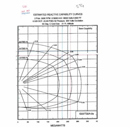
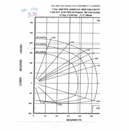
6 ATTACHMENT #1 (Evaluation for Compliance to the PJM Tariff Power Factor Requirement) 6
7 7
8 8
9 ATTACHMENT #2 (Stabillity Analysis contingency cases evaluated) 9
10 R81 (Emile 230KV) BREAKER CLEARING TIMES (CYCLES) Station Primary (3ph/slg) Stuck Breaker (total) Zone 2 (total) re-closing 230 kv kv Less than 138 kv ALL FAULTS ARE STABLE CRITERIA FAULTS R81-1a R81-1b R81-2a R81-3a R81-4a R81-4b 230/138 kv Emilie 230 kv on North Bus Emilie 230 kv on Emilie 230 kv north bus, stuck at Emilie (L/O Emilie 230/138 kv Circuit 1) Emilie 230 kv on Emilie Croydon 230 kv Emilie 230 kv on Emilie Eddington Tap 230 kv Emilie 230 kv on South Bus Emilie 230 kv on Emilie 230 kv south bus, stuck at Emilie (L/O Emilie Circuit 2) R81-5a Emilie 230 kv on Emilie 230/138 kv Circuit 2 R81-5b Emilie 230 kv on Emilie 230/138 kv Circuit 2, stuck at Emilie (L/O Emilie 230 kv south bus) R81-6a R81-6b Croydon 230 kv on Croydon Cox s Corner 230 kv Croydon 230 kv on Croydon Cox s Corner 230 kv, stuck at Croydon (L/O Croydon-Emilie 230 KV Circuit 1) R81-7a R81-7b Croydon 230 kv on Croydon Eddington Tap 230 kv Corner Eddington 230 kv on Eddington Eddington Tap 230 kv, stuck at Eddington (L/O Edding-Holmes Circuit 1) R81-8a R81-9a Emilie 138 kv on North Bus Emilie 138 kv on South bus 10
11 ATTACHMENT #3 (Queue R81 Generator and Generator Step-up Transformer Data) 11
12 Unit Capability Data Gross MW Output GSU MW Losses Unit Auxiliary Load MW Station Service Load MW Net MW Capacity Net MW Capacity = (Gross MW Output - GSU MW Losses* Unit Auxiliary Load MW - Station Service Load MW) Queue Letter/Position/Unit ID: R81 Primary Fuel Type: STEAM Maximum Summer (92º F ambient air temp.) Net MW Output**: Maximum Summer (92º F ambient air temp.) Gross MW Output: Minimum Summer (92º F ambient air temp.) Gross MW Output: Maximum Winter (30º F ambient air temp.) Gross MW Output: Minimum Winter (30º F ambient air temp.) Gross MW Output: Gross Reactive Power Capability at Maximum Gross MW Output Please include Reactive Capability Curve (Leading and Lagging): [-80,150] Individual Unit Auxiliary Load at Maximum Summer MW Output (MW/MVAR): N/A Individual Unit Auxiliary Load at Minimum Summer MW Output (MW/MVAR): N/A Individual Unit Auxiliary Load at Maximum Winter MW Output (MW/MVAR): N/A Individual Unit Auxiliary Load at Minimum Winter MW Output (MW/MVAR): N/A Station Service Load (MW/MVAR): N/A * GSU losses are expected to be minimal. ** Your project s declared MW, as first submitted in Attachment N, and later confirmed or modified by the Impact Study Agreement, should be based on either the 92 o F Ambient Air Temperature rating of the unit(s) or, if less, the declared Capacity rating of your project. 12
13 Unit Generator Dynamics Data Queue Letter/Position/Unit ID: R81 MVA Base (upon which all reactances, resistance and inertia are calculated): 319 Nominal Power Factor: 0.85 Terminal Voltage (kv): 18 Unsaturated Reactances (on MVA Base) Direct Axis Synchronous Reactance, X d(i) : Direct Axis Transient Reactance, X d(i): Direct Axis Sub-transient Reactance, X d(i): Quadrature Axis Synchronous Reactance, Xq(i): Quadrature Axis Transient Reactance, X q(i): Quadrature Axis Sub-transient Reactance, X q(i): Stator Leakage Reactance, Xl: Negative Sequence Reactance, X2(i): Zero Sequence Reactance, X0: Saturated Sub-transient Reactance, X d(v) (on MVA Base): Armature Resistance, Ra (on MVA Base): Time Constants (seconds) Direct Axis Transient Open Circuit, T do : 6.31 Direct Axis Sub-transient Open Circuit, T do : Quadrature Axis Transient Open Circuit, T qo : Quadrature Axis Sub-transient Open Circuit, T qo : Inertia, H (kw-sec/kva, on KVA Base): Speed Damping, D: 0.0 Saturation Values at Per-Unit Voltage [S(1.0), S(1.2)]: [0.0572/0.4604] Units utilize a Generator model. 13
14 Unit GSU 1 Data Queue Letter/Position/Unit ID: R81 Generator Step-up Transformer MVA Base: 192 Generator Step-up Transformer Impedance (R+jX, or %, on transformer MVA Base): _j Generator Step-up Transformer Reactance-to-Resistance Ration (X/R): Generator Step-up Transformer Rating (MVA): 192 Generator Step-up Transformer Low-side Voltage (kv): 18 Generator Step-up Transformer High-side Voltage (kv): 242 Generator Step-up Transformer Off-nominal Turns Ratio: 1.0 Generator Step-up Transformer Number of Taps and Step Size: 1/2% each 14
15 Unit Capability Data Gross MW Output GSU MW Losses Unit Auxiliary Load MW Station Service Load MW Net MW Capacity Net MW Capacity = (Gross MW Output - GSU MW Losses* Unit Auxiliary Load MW - Station Service Load MW) Queue Letter/Position/Unit ID: R81 Primary Fuel Type: GAS Maximum Summer (92º F ambient air temp.) Net MW Output**: Maximum Summer (92º F ambient air temp.) Gross MW Output: Minimum Summer (92º F ambient air temp.) Gross MW Output: 73.8 Maximum Winter (30º F ambient air temp.) Gross MW Output: Minimum Winter (30º F ambient air temp.) Gross MW Output: 90 Gross Reactive Power Capability at Maximum Gross MW Output Please include Reactive Capability Curve (Leading and Lagging): [-50,85] Individual Unit Auxiliary Load at Maximum Summer MW Output MW/MVAR):15.1/9.3 Individual Unit Auxiliary Load at Minimum Summer MW Output (MW/MVAR):6.8/4.2 Individual Unit Auxiliary Load at Maximum Winter MW Output (MW/MVAR):7.1/4.4 Individual Unit Auxiliary Load at Minimum Winter MW Output (MW/MVAR):7.2/4.4 Station Service Load (MW/MVAR): 0.15/073 * GSU losses are expected to be minimal. ** Your project s declared MW, as first submitted in Attachment N, and later confirmed or modified by the Impact Study Agreement, should be based on either the 92 o F Ambient Air Temperature rating of the unit(s) or, if less, the declared Capacity rating of your project. 15
16 Unit Generator Dynamics Data Queue Letter/Position/Unit ID: R81 MVA Base (upon which all reactances, resistance and inertia are calculated): 234 Nominal Power Factor: 0.85 Terminal Voltage (kv): 18 Unsaturated Reactances (on MVA Base) Direct Axis Synchronous Reactance, X d(i) : Direct Axis Transient Reactance, X d(i): Direct Axis Sub-transient Reactance, X d(i): Quadrature Axis Synchronous Reactance, Xq(i): Quadrature Axis Transient Reactance, X q(i): Quadrature Axis Sub-transient Reactance, X q(i): Stator Leakage Reactance, Xl: Negative Sequence Reactance, X2(i): Zero Sequence Reactance, X0: Saturated Sub-transient Reactance, X d(v) (on MVA Base): Armature Resistance, Ra (on MVA Base): Time Constants (seconds) Direct Axis Transient Open Circuit, T do : Direct Axis Sub-transient Open Circuit, T do : Quadrature Axis Transient Open Circuit, T qo : Quadrature Axis Sub-transient Open Circuit, T qo : Inertia, H (kw-sec/kva, on KVA Base): Speed Damping, D: 0.0 Saturation Values at Per-Unit Voltage [S(1.0), S(1.2)]: [0.0575/0.4411] Units utilize a Generator model. 16
17 Unit GSU Data Queue Letter/Position/Unit ID: R81 Generator Step-up Transformer MVA Base: 114 Generator Step-up Transformer Impedance (R+jX, or %, on transformer MVA Base): _j Generator Step-up Transformer Reactance-to-Resistance Ration (X/R): 48 Generator Step-up Transformer Rating (MVA): 114 Generator Step-up Transformer Low-side Voltage (kv): 18 Generator Step-up Transformer High-side Voltage (kv): 242 Generator Step-up Transformer Off-nominal Turns Ratio: 1.0 Generator Step-up Transformer Number of Taps and Step Size: 1/2% each 17
18 PJM Generator Interconnection R81 Emilie (Fords Mill) MW Impact Study April 2008 DMS #
19 General Queue R81 Emilie (Fords Mills) is a Fairless Energy, LLC request to obtain an additional MWs 1 of Capacity Interconnection Rights ( to MW) at Emilie 230 kv substation for generator uprates (add chillers) planned for each of the existing six generators (configured as two 2 x 1 combined cycle plants). All generator uprates are scheduled to be completed by June Note 1: Queue R81 reduced its request size from 180 MW to MW after the Feasibility Study was completed and as a result of FERC Docket no.el08-36 R81 Settlement Agreement. Direct Connection The R81 is connected as shown on Figure 1 below. No additional Direct Connection facilities are required. 2
20 Network Impacts The Queue R81 project was studied as a MW increase in Capacity Interconnection Rights at Emilie 230 kv substation for the existing Fords Mills (Fairless) generation. Project R81 was evaluated for compliance with reliability criteria for summer peak conditions in Potential network impacts were as follows: NETWORK IMPACTS Generator Deliverability (Single or N-1 contingencies for the Capacity portion only of the interconnection) 1. The Richmond to Holmesurg Tap 230 kv line reactor at Richmond (from bus 4024 to bus 4269 ckt 1) loads from 98.2% to 109.0% of its emergency rating (374MVA) for the single line contingency outage of Croydon Burlington Mt. Laurel Cox s Corner 230 kv line (PS59). This project contributes approximately 40.7 MW to cause this thermal violation. 2. The Richmond to Holmesburg Tap 230 kv line (from bus 4145 to bus 4024 ckt 1) loads from 98.4% to 109.2% of its emergency rating (374MVA) for the single line contingency outage of Croydon Burlington Mt. Laurel Cox s Corner 230 kv line (PS59). This project contributes approximately 40.7MW to cause this thermal violation. 3. The Emilie Neshaminy 138kV line (from bus 4667 to bus 4218 ckt 1) loads from 97.5% to 102.1% of its normal rating (550MVA) for non-contingency (normal) condition. This project contributes approximately 25.0 MW to cause this thermal violation. Multiple Facility Contingency (Double Circuit Tower Line contingencies only for the full energy output. Stuck breaker and bus fault contingencies will be performed for the Impact Study) No problems identified. Short Circuit Short circuit analysis is not required since there is no change to the impedance of the generating units or the generator step-up transformers.. Stability Analysis Will be performed for the R81Facilities Study. Evaluation for Compliance to the PJM Power Factor Requirements Queue R81 meets or exceeds the Power Factor requirement of 0.90 lag to 0.95 lead at the generator s terminals for a total aggregate Max Facility Output of 1095 MW. Also see Attachment #1. 3
21 Contribution to Previously Identified Overloads (R81 contributes to the following contingency overloads, i.e. Network Impacts, identified for earlier generation or transmission interconnection projects in the PJM Queue) General Notes pertaining to cost allocation rules for overloads: (also see the PJM Tariff and Manual 14) The first project to cause an overload has cost responsibility. If this Queue is not the first project to cause the overload, a threshold of; a) 1% increase in overloaded facility loading must be caused by the this Queue generation, and b) This Queue s MW contribution of 5.0 MW or greater are both required for cost allocation responsibility. And If not the first project to cause the overload but both conditions above are met, then a threshold of Either of the following are also required for cost allocation responsibility; a) a 5% generator DFAX* (5 MW for a generation request size of 100 MW), or (b) This Queue s generation must cause an increase of 5% to the overloaded facility loading * DFAX may not be equal to this Queue s contribution divided by generator MW size in some cases. 4. This project contributes approximately 32.5 MW to the contingency loading of the Peach Bottom to Conastone 500kV line (from bus 13 to bus 4 ckt 1) previously loaded above its emergency rating (2598 MVA) for the single line contingency outage of the Hunterstown Conastone 500 kv line. 5. This project contributes 9.5 MW to the contingency loading of the Nottingham Graceton 230 kv line # reactor, at Nottingham, previously overloaded above its emergency rating (627MVA) by earlier queued project R39 for the outage of the Conastone Peach Bottom 500 kv line with a stuck breaker at Conastone. 6. This project contributes 9.5MW to the contingency loading of the Nottingham Peach Bottom Tap section of the Notingham Graceton 230kV line # previously overloaded above its emergency rating (627MVA) by earlier queued projects for the outage of Conastone Peach Bottom 500 kv line with a stuck breaker at Conastone. 7. This project contributes 9.5MW to the contingency loading of the Peach Bottom Tap to Graceton section of the Notingham Graceton 230kV line # previously overloaded above its emergency rating (627MVA) by earlier queued projects for the outage of Conastone Peach Bottom 500 kv line with a stuck breaker at Conastone. 4
22 NETWORK UPGRADE REQUIREMENTS New System Reinforcements (Upgrades required to mitigate reliability criteria violations, i.e. Network Impacts, initially caused by the addition of this project generation) 1. Richmond to Holmesurg Tap 230 kv line reactor at Richmond at 109.0% of its emergency rating. Upgrade requirement (Network Upgrade number n0887): Replace the reactor with a higher rated reactor at an estimated cost of $200,000. Lead time required for replacement is 18 months. 2. Richmond to Holmesburg Tap 230 kv line at 109.2% of its contingency rating. Upgrade requirement (Network Upgrade number n0888):: Replace terminal equipment at Richmond at an estimated cost of $2,000,000. Also, perform a Railroad induction study and perform required mitigation to reduce induction impacts at an estimated cost of an additional $2,000,000. Total cost estimate is $4,000,000. Lead time required for this upgrade is 30 months. The new line rating will be 457 MVA normal / 574 MVA emergency. 3. Emilie Neshaminy 138kV line at 102.1% of its normal rating. Upgrade requirement (Network Upgrade number n0889): Replace terminal equipment at Neshaminy and Emilie at an estimated cost of $500,000. Lead time required for replacement is 24 months. Contribution to Previously Identified System Reinforcements (Overloads initially caused by prior Queue positions with additional contribution to overloading by this project. This project may have a % allocation cost responsibility which will be calculated and reported for the Impact Study) 4. Peach Bottom to Conastone 500 kv line upgrade. BG&E portion of the Peach Bottom to Conastone #5012 line (MD/PA state line to Conastone): The BG&E portion to Peach Bottom to Conastone 500 kv line is rated at 3734 MVA. The contingency overload is approximately 3455 MVA, therefore the BG&E portion of the line itself does not require upgrade. However, three 500kV breakers at Conastone will exceed their emergency rating of 3000 amps. 5
23 BG&E Upgrade requirement (Network Upgrade number n0890): Rebuild or upgrade the three Conastone circuit breakers at an estimated cost of $1,500,000 ($500,000 per breaker) with a required lead time of 6-12 months. Queue R81 cost allocation is 2.6% or an estimated cost of $38,450. The cost allocation breakdown for the above upgrade is as follows: Queue MW Percentage Cost $K (total cost = 1500K) Q % R % R % R % R % R % R % R % R % R % R % R % PECO Energy portion of the Peach Bottom to Conastone #5012 line (MD/PA state line to Peach Bottom): #1 PECO Upgrade Requirement (Network Upgrade number n0891):: Replace metering equipment at the Peach Bottom Terminal at an estimated total cost of $100,000. Queue R81 s cost allocation is 2.6% or an estimated cost of $2,560. Lead time required for metering equipment replacement is 24 months. The estimated new rating (PECO) is 2707 MVA normal / 3112 MVA emergency. Cost allocation breakdown for the above upgrade is as follows: Queue MW Percentage Cost $K (total cost = 100K) Q % R % 8.81 R % 4.53 R % 9.64 R % 4.57 R % R % 4.94 R % 5.95 R %
24 R % 2.72 R % 7.15 R % 2.56 #2 PECO Upgrade Requirement (Network Upgrade number n0892):: Replace two circuit breakers at Peach Bottom 500 kv substation at an estimated total cost of $1,300,000 ($650,000 per breaker). Queue R81 cost allocation is 11.8% or $153,470. Estimated lead time for the breaker replacements is 30 months. The new estimated rating is 3365 MVA normal / 3463 MVA emergency. Cost allocation breakdown for the above upgrade is as follows: Queue MW Percentage Cost $K (total cost = 1300K) R % R % R % R % R % Nottingham Graceton 230 kv line # reactor overload. Upgrade Requirement (Network Upgrade n0896) Relocate the Peach Bottom Conastone 500 kv line (#5012) into a new two breaker bay at Conastone 500 kv substation. The total estimated cost is $7,000,000. Queue R81 s allocated cost is % or an estimated cost of $1,528,700. Estimated lead time for the reactor replacement is months. This upgrade also satisfies upgrade requirements for 6 and 7. Cost allocation breakdown for the above upgrade is as follows: Cost ($M Queue MW Contribution Percentage )total cost = $7M R % R % R % Nottingham Peach Bottom Tap section of the Notingham Graceton 230kV line # overload. See upgrade 5 (Network Upgrade number n0896) on the previous page, this upgrade also satisfies upgrade requirement number 6. 7
25 7. Peach Bottom Tap to Graceton section of the Notingham Graceton 230kV line # overload. See upgrade 5 (Network Upgrade number n0896) on the previous page, this upgrade also satisfies upgrade requirement number 7. 8
26 ATTACHMENT #1 (Evaluation for Compliance to the PJM Tariff Power Factor Requirement) 9
27 10
28 11
PJM Generator Interconnection Request Queue #R60 Robison Park-Convoy 345kV Impact Study September 2008
 PJM enerator Interconnection Request Queue #R60 Robison Park-Convoy 345kV Impact Study 504744 September 2008 PJM Interconnection 2008. All rights reserved R60 Robison Park-Convoy 345kV Impact Study eneral
System Impact Study Report
 Report For: NTE Carolinas II, LLC ( Customer ) Queue #: 42432-01 Service Location: Rockingham County, NC Total Output: 477 MW (summer) / 540 MW (winter) Commercial Operation Date: 12/1/2020 42432-01 SIS
Feasibility Study Report
 Generator Interconnection Request Feasibility Study Report For: Customer --- Service Location: Rutherford County Total Output: 79.2 MW Commercial Operation Date: 9/1/2014 In-Service Date (if given): 9/1/2014
Interconnection Feasibility Study Report GIP-222-FEAS-R3
 Interconnection Feasibility Study Report GIP-222-FEAS-R3 System Interconnection Request #222 48 MW Steam Generating Facility Pictou County (53N) 2010 07 30 Control Centre Operations Nova Scotia Power Inc.
Legal Name of the Customer (or, if an individual, individual's name): Name: Contact Person: Mailing Address: Physical Address: City: State: Zip Code:
: Name: Contact Person: Mailing Address: Physical Address: City: State: Zip Code:") Generating Facility Level 2 or 3 Interconnection Review (For Generating Facilities with Electric Nameplate Capacities no Larger than 20 MW) Instructions An Interconnection Customer who requests a Utah
Generating Facility Level 2 or 3 Interconnection Review (For Generating Facilities with Electric Nameplate Capacities no Larger than 20 MW) Instructions An Interconnection Customer who requests a Utah
Level 2, Level 3 & Level 4 Interconnection Request Application Form (Greater than 25 kw to 10 MVA or less)
") Level 2, Level 3 & Level 4 Interconnection Request Application Form (Greater than 25 kw to 10 MVA or less) Interconnection Customer Contact Information Name Alternative Contact Information (if different
Level 2, Level 3 & Level 4 Interconnection Request Application Form (Greater than 25 kw to 10 MVA or less) Interconnection Customer Contact Information Name Alternative Contact Information (if different
Interconnection Feasibility Study Report GIP-226-FEAS-R3
 Interconnection Feasibility Study Report GIP-226-FEAS-R3 System Interconnection Request #226 70 MW Wind Generating Facility Kings County (L-6013) 2010 07 21 Control Centre Operations Nova Scotia Power
Generator Interconnection Facilities Study For SCE&G Two Combustion Turbine Generators at Hagood
 Generator Interconnection Facilities Study For SCE&G Two Combustion Turbine Generators at Hagood Prepared for: SCE&G Fossil/Hydro June 30, 2008 Prepared by: SCE&G Transmission Planning Table of Contents
Generation Interconnection Feasibility Study Report. For. PJM Generation Interconnection Request Queue Position Y Linden 138 kv & 230 kv
 Generation Interconnection Feasibility Study Report For PJM Generation Interconnection Request Queue Position Y3-051 Linden 138 kv & 230 kv September / 2013 PJM Interconnection 2013. All rights reserved.
Level 2, Level 3 & Level 4 Interconnection Request Application Form (Greater than 10 kva to 10 MVA or less)
") Section 466.APPENIX C Levels 2 to 4 Application Level 2, Level 3 & Level 4 Interconnection Request Application Form (Greater than 10 kva to 10 MVA or less) Interconnection Customer Contact Information
Section 466.APPENIX C Levels 2 to 4 Application Level 2, Level 3 & Level 4 Interconnection Request Application Form (Greater than 10 kva to 10 MVA or less) Interconnection Customer Contact Information
Feasibility Study Report
 Report For: Fresh Air Energy II, LLC ( Customer ) Queue #: Service Location: Chester County, SC Total Output Requested By Customer: 74.5 MW Commercial Operation Date Requested By Customer: 1/7/2019 Feasibility
PID 274 Feasibility Study Report 13.7 MW Distribution Inter-Connection Buras Substation
 PID 274 Feasibility Study Report 13.7 MW Distribution Inter-Connection Buras Substation Prepared by: Entergy Services, Inc. T & D Planning L-ENT-17A 639 Loyola Avenue New Orleans, LA 70113 Rev Issue Date
Cromby Units 1 and 2 and Eddystone Units 1 and 2. Deactivation Study
 Cromby Units 1 and 2 and Eddystone Units 1 and 2 Deactivation Study Original Posting Date: March 2, 2010 Updated May 10, 2010 Updated June 7, 2010 Updated September 7, 2010 General PJM received notice
Maryland Level 2, Level 3 & Level 4 Interconnection Request Application Form (Greater than 10 kw to 10 MW or less)
") Maryland Level 2, Level 3 & Level 4 Interconnection Request Application Form (Greater than 10 kw to 10 MW or less) Interconnection Customer Contact Information Name: Address: Alternative Contact Information
Maryland Level 2, Level 3 & Level 4 Interconnection Request Application Form (Greater than 10 kw to 10 MW or less) Interconnection Customer Contact Information Name: Address: Alternative Contact Information
CUSTOMER/ TWIN ARROWS PROJECT
 A subsidiary of Pinnacle West Capital Corporation CUSTOMER/ TWIN ARROWS PROJECT V1 Facility Study Report APS Contract 52149 Prepared by: Arizona Public Service Company Transmission & Distribution Asset
MILLIGAN SOLAR PROJECT
 February 16, 2009 Page 1 of 18 A subsidiary of Pinnacle West Capital Corporation MILLIGAN SOLAR PROJECT FINAL Feasibility Study Report APS Contract 52115 Prepared by: Arizona Public Service Company Transmission
Maryland Level 2, Level 3 & Level 4 Interconnection Request Application Form (Greater than 10 kw to 10 MW or less)
") Maryland Level 2, Level 3 & Level 4 Interconnection Request Application Form (Greater than 10 kw to 10 MW or less) Interconnection Customer Contact Information Name: Address: City: Telephone (aytime):
Maryland Level 2, Level 3 & Level 4 Interconnection Request Application Form (Greater than 10 kw to 10 MW or less) Interconnection Customer Contact Information Name: Address: City: Telephone (aytime):
Feasibility Study Report
 Report For: Orion Renewable Resources LLC ( Customer ) Queue #: Service Location: Rockingham County, NC Total Output Requested By Customer: 100 MW Commercial Operation Date Requested By Customer: 11/1/2019
Elbert County 500 MW Generation Addition Interconnection Feasibility Study Report OASIS POSTING # GI
 Executive Summary Elbert County 500 MW Generation Addition Interconnection Feasibility Study Report OASIS POSTING # GI-2003-2 Xcel Energy Transmission Planning January 2004 This Interconnection Feasibility
Generator Interconnection System Impact Study For
 Generator Interconnection System Impact Study For Prepared for: January 15, 2015 Prepared by: SCE&G Transmission Planning Table of Contents General Discussion... Page 3 I. Generator Interconnection Specifications...
EL PASO ELECTRIC COMPANY SHORT CIRCUIT ANALYSIS FOR XXX S PROPOSED GENERATION INTERCONNECTION
 EL PASO ELECTRIC COMPANY SHORT CIRCUIT ANALYSIS FOR XXX S PROPOSED GENERATION INTERCONNECTION El Paso Electric Company System Operations Department System Planning Section August 2006 I. INTRODUCTION The
Interconnection System Impact Study Report Request # GI
 Executive Summary Interconnection System Impact Study Report Request # GI-2008-23 34 MW Solar Generation Ranch at Hartsel, Colorado Public Service Company of Colorado Transmission Planning August 19, 2010
Generation Interconnection Feasibility Study For XXXXXXXXXXXXXXXXXXXXXX MW generator at new Western Refinary Substation
 Generation Interconnection Feasibility Study For XXXXXXXXXXXXXXXXXXXXXX 131-250 MW generator at new Western Refinary Substation System Planning Section April, 2005 TABLE OF CONTENT 1 EXECUTIVE SUMMARY
Feasibility Study. Shaw Environmental, Inc. 12MW Landfill Gas Generation Interconnection. J.E.D. Solid Waste Management Facility. Holopaw Substation
 Feasibility Study Shaw Environmental, Inc. 12MW Landfill Gas Generation Interconnection J.E.D. Solid Waste Management Facility Holopaw Substation September 2013 1 of 12 Table of Contents GENERAL... 3 SHORT
Interconnection Feasibility Study Report GIP-023-FEAS-R1. Generator Interconnection Request # MW Wind Generating Facility Inverness (L6549), NS
, NS") Interconnection Feasibility Study Report GIP-023-FEAS-R1 Generator Interconnection Request # 23 100 MW Wind Generating Facility Inverness (L6549), NS February 16, 2006 Control Centre Operations Nova Scotia
Interconnection Feasibility Study Report GIP-023-FEAS-R1 Generator Interconnection Request # 23 100 MW Wind Generating Facility Inverness (L6549), NS February 16, 2006 Control Centre Operations Nova Scotia
Merchant Transmission Interconnection PJM Impact Study Report. PJM Merchant Transmission Request Queue Position X3-028.
 Merchant Transmission Interconnection PJM Impact Study Report For PJM Merchant Transmission Request Queue Position X3-028 Breed 345 kv October/2014 System Impact Study Breed 345 kv Merchant Transmission
Final Draft Report. Assessment Summary. Hydro One Networks Inc. Longlac TS: Refurbish 115/44 kv, 25/33/ General Description
 Final Draft Report Assessment Summary Hydro One Networks Inc. : Refurbish 115/44 kv, 25/33/42 MVA DESN Station CAA ID Number: 2007-EX360 1.0 General Description Hydro One is proposing to replace the existing
Supplemental Report on the NCTPC Collaborative Transmission Plan
 Supplemental Report on the NCTPC 2007-2017 Collaborative Transmission Plan May 16, 2008 1 Table of Contents I. Executive Summary...1 II. Richmond-Fort Bragg Woodruff Street 230 kv Line...2 II.A. Need for
Falcon-Midway 115 kv Line Uprate Project Report
 Falcon-Midway 115 kv Line Uprate Project Report 12/1/2008 1 Background The function of this project is to uprate the 26.7 miles of Tri-State s 115 kv line between Midway and Falcon substations from 50
Georgia Transmission Corporation Georgia Systems Operations Corporation
 Georgia Transmission Corporation Georgia Systems Operations Corporation Reactive Power Requirements for Generating Facilities Interconnecting to the Georgia Integrated Transmission System with Georgia
New 115 kv Disconnect Switches at Bloomsburg MTS
 115 kv Line tap from C9 to Bloomsburg MTS & New Bus Tie Switch CAA ID Number: 2007-EX353 Final Draft ASSESSMENT SUMMARY 1. GENERAL DESCRIPTION Norfolk TS and Bloomsburg MTS are supplied by a single 115
100 MW Wind Generation Project
 A subsidiary of Pinnacle West Capital Corporation 100 MW Wind Generation Project CUSTOMER FINAL Feasibility Study Results By Transmission Planning, APS December 21, 2007 Executive Summary This Feasibility
Reliability Analysis Update
 Reliability Analysis Update Transmission Expansion Advisory Committee October 11, 2018 Proposal Window Exclusion Definitions The following definitions explain the basis for excluding flowgates and/or projects
CUSTOMER / ACCOUNT INFORMATION Electric Utility Customer Information (As shown on utility bill)
") GENERATOR INTERCONNECTION APPLICATION Category 2 (Combined) For All Projects with Aggregate Generator Output of More Than 20 kw but Less Than or Equal to 150 kw Also Serves as Application for Category
GENERATOR INTERCONNECTION APPLICATION Category 2 (Combined) For All Projects with Aggregate Generator Output of More Than 20 kw but Less Than or Equal to 150 kw Also Serves as Application for Category
PSNH INTERCONNECTION REQUEST
 PSNH INTERCONNECTION REQUEST Send the completed Interconnection Request and required attachments to: Public Service of New Hampshire Attn: Michael Motta, Senior Engineer Supplemental Energy Sources P.
Project #148. Generation Interconnection System Impact Study Report
 Project #148 Generation Interconnection System Impact Study Report June 05, 2012 Electric Transmission Planning Table of Contents Table of Contents... 2 Executive Summary... 3 Energy Resource Interconnection
Interconnection Feasibility Study Report Request # GI Draft Report 600 MW Wind Generating Facility Missile Site 230 kv Substation, Colorado
 Executive Summary Interconnection Feasibility Study Report Request # GI-2016-6 Draft Report 600 MW Wind Generating Facility Missile Site 230 kv Substation, Colorado Public Service Company of Colorado Transmission
EL PASO ELECTRIC COMPANY (EPE) FACILITIES STUDY FOR PROPOSED HVDC TERMINAL INTERCONNECTION AT NEW ARTESIA 345 KV BUS
 FACILITIES STUDY FOR PROPOSED HVDC TERMINAL INTERCONNECTION AT NEW ARTESIA 345 KV BUS") EL PASO ELECTRIC COMPANY (EPE) FACILITIES STUDY FOR PROPOSED HVDC TERMINAL INTERCONNECTION AT NEW ARTESIA 345 KV BUS El Paso Electric Company System Operations Department System Planning Section May 2004
EL PASO ELECTRIC COMPANY (EPE) FACILITIES STUDY FOR PROPOSED HVDC TERMINAL INTERCONNECTION AT NEW ARTESIA 345 KV BUS El Paso Electric Company System Operations Department System Planning Section May 2004
Rogers Road to Clubhouse 230kV New Transmission Line April 1, 2016
 New Transmission Line April 1, 2016 The enclosed information is proprietary to PSE&G and is provided solely for your use. It should not be copied, reproduced, or shared with others without PSE&G s prior
Impacts of MISO DPP-2016-February (West, ATC, MI, South) Projects on PJM Facilities
 Projects on PJM Facilities") Impacts of MISO DPP-2016-February (West, ATC, MI, South) 1. MISO generators studied: Projects on PJM Facilities Net MW size (Summer) Net MW size (Winter) Service DPP Project Type Region Fuel Type POI J432
Impacts of MISO DPP-2016-February (West, ATC, MI, South) 1. MISO generators studied: Projects on PJM Facilities Net MW size (Summer) Net MW size (Winter) Service DPP Project Type Region Fuel Type POI J432
Wheeler Ridge Junction Substation Project Description and Functional Specifications for Competitive Solicitation
 Wheeler Ridge Junction Substation Project Description and Functional Specifications for Competitive Solicitation 1. Description In the 2013-2014 Transmission Planning Cycle, the ISO approved the construction
Sub Regional RTEP Committee Western Region ATSI
 Sub Regional RTEP Committee Western Region ATSI February 20, 2019 1 ATSI Needs Stakeholders must submit any comments within 10 days of this meeting in order to provide time necessary to consider these
Interconnection Feasibility Study Report GIP-157-FEAS-R2
 Interconnection Feasibility Study Report GIP-157-FEAS-R2 System Interconnection Request #157 100.5 MW Wind Generating Facility Guysborough County (L-6515) 2009 09 14 Control Centre Operations Nova Scotia
CATEGORY 2 GENERATOR INTERCONNECTION APPLICATION
 CATEGORY 2 GENERATOR INTERCONNECTION APPLICATION FOR ALL PROJECTS WITH AGGREGATE GENERATOR OUTPUT OF MORE THAN 20 KW BUT LESS THAN OR EQUAL TO 150 KW Also Serves as Application for Category 2 Net Metering
Electric Utility Contact Information Indiana Michigan Power
 CATEGORY 2 GENERATOR INTERCONNECTION APPLICATION FOR ALL PROJECTS WITH AGGREGATE GENERATOR OUTPUT OF MORE THAN 20 KW BUT LESS THAN OR EQUAL TO 150 KW Also Serves as Application for Category 2 Net Metering
Interconnection Feasibility Study Report GIP-084-FEAS-R2
 Interconnection Feasibility Study Report GIP-084-FEAS-R2 System Interconnection Request #84 50 MW Wind Generating Facility Pictou County (L-7004) August 17, 2007 Control Centre Operations Nova Scotia Power
XXXXXXXXXXXXXXXXXXXX GENERATION INTERCONNECTION FACILITIES STUDY SHORT CIRCUIT ANALYSIS FOR PROPOSED GENERATION AT NEWMAN 115 kv BUS
 XXXXXXXXXXXXXXXXXXXX GENERATION INTERCONNECTION FACILITIES STUDY SHORT CIRCUIT ANALYSIS FOR PROPOSED GENERATION AT NEWMAN 115 kv BUS El Paso Electric Company System Operations Department System Planning
APPENDIX I: Description and Functional Specifications for Transmission Facilities Eligible for Competitive Solicitation
 APPENDIX I: Description and Functional Specifications for Transmission Facilities Eligible for Competitive Solicitation Intentionally left blank F1 Description and Functional Specifications of Proposed
Transmission Competitive Solicitation Questions Log Question / Answer Matrix Harry Allen to Eldorado 2015
 No. Comment Submitted ISO Response Date Q&A Posted 1 Will the ISO consider proposals that are not within the impedance range specified? Yes. However, the benefits estimated and studies performed by the
Project #94. Generation Interconnection System Impact Study Report Revision
 Project #94 Generation Interconnection System Impact Study Report Revision October 2, 2009 Electric Transmission Planning Table of Contents Table of Contents...2 Executive Summary...3 Energy Resource Interconnection
XXXXXXXXXXXXXXXXXXXXXXXXXXXXXXXXXXXXXX TRANSMISSION AND FACILITIES STUDY. Short Circuit Analysis
 XXXXXXXXXXXXXXXXXXXXXXXXXXXXXXXXXXXXXX TRANSMISSION AND FACILITIES STUDY Short Circuit Analysis System Operations Department System Planning Section March 2001 I. Introduction XXXXXXXXXXXXXXXXXXXXXXXXXXXXXXXXX
Connection of Power Generating Modules to DNO Distribution Networks in accordance with EREC G99
 Connection of Power Generating Modules to DNO Distribution Networks in accordance with EREC G99 Version 1 August 2018 www.energynetworks.org 2 Introduction Connection of Power Generating Modules to DNO
Interconnection Feasibility Study Report GIP-369-FEAS-R1
 Interconnection Feasibility Study Report GIP-369-FEAS-R1 System Interconnection Request #369 50 MW Wind Generating Facility Cumberland County (L-6513) 2012-02-09 Control Centre Operations Nova Scotia Power
BHARAT ALUMINIUM COMPANY LTD. SPECIFICATIONS FOR SYNCHRONOUS GENERATOR GENERAL Make : Jinan Power Equipment Factory Type : WX2
 BHARAT ALUMINIUM COMPANY LTD. SPECIFICATIONS FOR SYNCHRONOUS GENERATOR 1.00.00 GENERAL 1.01.00 Make : Jinan Power Equipment Factory 1.02.00 Type : WX21Z-073LLT 1.03.00 Reference Standard : GB/T7064-2002
P734H - Technical Data Sheet
 P734H - Technical Data Sheet Standards STAMFORD industrial alternators meet the requirements of the relevant parts of the BS EN 60034 and the relevant section of other international standards such as BS5000,
Request for Payment Instructions Wholesale Distribution Access Tariff (WDAT) Attachment I - GIP
 Attachment I - GIP") Grid Interconnection & Contract Development Request for Payment Instructions Wholesale Distribution Access Tariff (WDAT) Attachment I - GIP Submittal Instructions Prior to submitting your application and
Grid Interconnection & Contract Development Request for Payment Instructions Wholesale Distribution Access Tariff (WDAT) Attachment I - GIP Submittal Instructions Prior to submitting your application and
Feasibility Study for the Q MW Solar Project
 Feasibility Study for the Q171 74.5 MW Solar Project August 2018 Bulk Transmission Planning, Florida i This document and any attachments hereto ( document ) is made available by Duke Energy Florida, LLC
XXXXXXXXXXXXXXXXXXXXXXXXXXXXXXX TRANSMISSION/GENERATION FEASIBILITY STUDY SHORT CIRCUIT ANALYSIS
 XXXXXXXXXXXXXXXXXXXXXXXXXXXXXXX TRANSMISSION/GENERATION FEASIBILITY STUDY SHORT CIRCUIT ANALYSIS El Paso Electric Company System Operations Department System Planning Section September 2001 Short Circuit
Request for Payment Instructions Rule 21 Export Submittal Instructions
 Grid Interconnection & Contract Development Request for Payment Instructions Rule 21 Export Submittal Instructions Prior to submitting your application and fee or deposit, please complete and submit this
TRANSMISSION PLANNING CRITERIA
 CONSOLIDATED EDISON COMPANY OF NEW YORK, INC. 4 IRVING PLACE NEW YORK, NY 10003-3502 Effective Date: TRANSMISSION PLANNING CRITERIA PURPOSE This specification describes Con Edison s Criteria for assessing
AMERICAN ELECTRIC POWER 2017 FILING FERC FORM 715 ANNUAL TRANSMISSION PLANNING AND EVALUATION REPORT PART 4 TRANSMISSION PLANNING RELIABILITY CRITERIA
 AMERICAN ELECTRIC POWER 2017 FILING FERC FORM 715 ANNUAL TRANSMISSION PLANNING AND EVALUATION REPORT PART 4 TRANSMISSION PLANNING RELIABILITY CRITERIA AEP Texas (comprised of its Central and North Divisions
NORTH CAROLINA INTERCONNECTION REQUEST APPLICATION FORM. Utility: Duke Energy Progress
 NORTH CAROLINA INTERCONNECTION REQUEST APPLICATION FORM ATTACHMENT 2 Utility: Duke Energy Progress Designated Utility Contact: Attention: Customer Owned Generation Mail Code ST13A E-Mail Address: Customerownedgeneration@duke-energy.com
System Impact Study Report PID MW (1612 MW Gross) Plant,
 Plant,") System Impact Study Report PID 204 1522 MW (1612 MW Gross) Plant, Fancy PT, LA Prepared by: Southwest Power Pool, Independent Coordinator of Transmission (SPP ICT) 415 North McKinley, Suite 140 Little
System Impact Study Report PID 204 1522 MW (1612 MW Gross) Plant, Fancy PT, LA Prepared by: Southwest Power Pool, Independent Coordinator of Transmission (SPP ICT) 415 North McKinley, Suite 140 Little
GENERATOR INTERCONNECTION APPLICATION
 GENERATOR INTERCONNECTION APPLICATION FOR ALL PROJECTS WITH AGGREGATE GENERATOR OUTPUT OF MORE THAN 150 KW BUT LESS THAN OR EQUAL TO 550 KW Also Serves as Application for Category 3 Net Metering (Note:
Connection of Power Generating Modules to DNO Distribution Networks in accordance with EREC G99
 Connection of Power Generating Modules to DNO Distribution Networks in accordance with EREC G99 Version 2, January 2019 www.energynetworks.org 2 Introduction Connection of Power Generating Modules to DNO
Feasibility Study for the Q MW Solar Project
 Feasibility Study for the Q174 74.5 MW Solar Project August 2018 Bulk Transmission Planning, Florida i This document and any attachments hereto ( document ) is made available by Duke Energy Florida, LLC
Interconnection System Impact Study Final Report February 19, 2018
 Interconnection System Impact Study Final Report February 19, 2018 Generator Interconnection Request No. TI-17-0225 248.4 MW (Alternate Project Output of 217.35 MW) Wind Energy Generating Facility In Goshen
Jemena Electricity Networks (Vic) Ltd
 Ltd") Jemena Electricity Networks (Vic) Ltd Embedded Generation - Technical Access Standards Embedded Generation - 5 MW or Greater ELE SP 0003 Public 1 October 2014 TABLE OF CONTENTS TABLE OF CONTENTS Abbreviations...
Jemena Electricity Networks (Vic) Ltd Embedded Generation - Technical Access Standards Embedded Generation - 5 MW or Greater ELE SP 0003 Public 1 October 2014 TABLE OF CONTENTS TABLE OF CONTENTS Abbreviations...
March 2017 to June 2017 Preliminary Interconnection Cluster Window System Impact Study 49.9 MW IA-PNM May 2018
 March 2017 to June 2017 Preliminary Interconnection Cluster Window System Impact Study 49.9 MW IA-PNM-2017-11 May 2018 Prepared by: Public Service Company of New Mexico Foreword This report is prepared
Sub Regional RTEP Committee - Southern. August 19, 2011
 Sub Regional RTEP Committee - Southern August 19, 2011 2011 RTEP Analysis Summary 2010 2015 Project Updates 2016 Analysis NERC Category A, B NERC Category C (N-1-1 in progress) Load Deliverability Generator
Consulting Agreement Study. Completed for Transmission Customer
 Completed for Transmission Customer Proposed Resource & Transmission Carbon County, MT & 230 kv Transmission in North Wyoming August 2016 Table of Contents 1.0 Description... 1 2.0 Overall Assumptions...
Short Circuit Analysis with New Generation Proposed by XXXXXXXXXXXXXXXXXXXXXX Pursuant to a Transmission and Facilities Study
 Short Circuit Analysis with New Generation Proposed by XXXXXXXXXXXXXXXXXXXXXX Pursuant to a Transmission and Facilities Study Study Performed by El Paso Electric Company System Planning Section - 1 I.
The Long-Range Transmission Plan
 The Long-Range Transmission Plan 2015 2025 Matt Koenig Presentation to ESPWG / TPAS October 29 th, 2015 Long-Range Transmission Plan Driver of the Plan is to maintain local reliability 10-year planning
Interconnection Feasibility Study Report GIP-IR373-FEAS-R1
 Interconnection Feasibility Study Report GIP-IR373-FEAS-R1 Generator Interconnection Request 373 109.5 MW Wind Generating Facility South Canoe Lake, NS Mar. 2, 2012 Control Centre Operations Nova Scotia
SYSTEM IMPACT STUDY EC300W ERIS FINAL REPORT. El Paso Electric Company
 SYSTEM IMPACT STUDY EC300W ERIS FINAL REPORT Prepared for: El Paso Electric Company Prepared by: Engineers, LLC 1526 Cole Boulevard Building 3, Suite 150 Lakewood, CO 80401 (303) 395-4018 FOREWORD This
Sub Regional RTEP Committee Mid-Atlantic
 Sub Regional RTEP Committee Mid-Atlantic September 24, 2014 1 Reliability Analysis Update 2 AE Transmission Zone Generation Deliverability Violation: The Middle 230/69 kv is overloaded for line fault stuck
Southern Company Interconnection Process. Dexter Lewis Research Engineer Research and Technology Management
 Southern Company Interconnection Process Dexter Lewis Research Engineer Research and Technology Management Southern Company Outline Southern Company GPC Solar Interconnection Process Application requirements
Transmission Improvements Plan for 575 MW Network Service Request Wansley CC 7 Generation Facility (OASIS # ) Georgia Transmission Corporation
 Georgia Transmission Corporation") Transmission Improvements Plan for 575 MW Network Service Request CC 7 Generation Facility (OASIS # 143556) Georgia Transmission Corporation November 11, 2010 CC7 TIP 11-11-2010 (2).docx PROBLEM STATEMENT
Transmission Improvements Plan for 575 MW Network Service Request CC 7 Generation Facility (OASIS # 143556) Georgia Transmission Corporation November 11, 2010 CC7 TIP 11-11-2010 (2).docx PROBLEM STATEMENT
Reliability Analysis Update
 Reliability Analysis Update Transmission Expansion Advisory Committee September 15, 2016 2016 RTEP Window #3 Anticipated Scope and Timeline Anticipated 2016 RTEP Window #3 Anticipated 2016 RTEP Window
Transmission Expansion Advisory Committee (TEAC) Recommendations to the PJM Board
 Recommendations to the PJM Board") Transmission Expansion Advisory Committee (TEAC) Recommendations to the PJM Board PJM Staff Whitepaper October 2013 EXECUTIVE SUMMARY On December 5, 2012 the PJM Board of Managers approved changes to the
Transmission Expansion Advisory Committee (TEAC) Recommendations to the PJM Board PJM Staff Whitepaper October 2013 EXECUTIVE SUMMARY On December 5, 2012 the PJM Board of Managers approved changes to the
South Dakota 890 Study
 South Dakota 890 Study September 16, 2011 South Dakota 890 Study Presentation of 890 Study results from 2011 Includes WAPA suggested system improvements and timelines Stakeholder Feedback Questions? 2
Generating unit functional document submission form
 Generating unit functional document submission form The below form must be completed and returned to generator.reports@aeso.ca. Supporting information to assist generating unit owners to complete this
DUKE ENERGY PROGRESS TRANSMISSION SYSTEM PLANNING SUMMARY
 DUKE ENERGY PROGRESS TRANSMISSION SYSTEM PLANNING SUMMARY Transmission Department Transmission Planning Duke Energy Progress TABLE OF CONTENTS I. SCOPE 3 II. TRANSMISSION PLANNING OBJECTIVES 3 III. TRANSMISSION
APPENDIX E: Project Need and Description
 APPENDIX E: Project Need and California ISO/MID E-1 Intentionally left blank California ISO/MID E-2 Tyler 60 kv Shunt Capacitor Installation of a 2x10 MVAR capacitor bank at Tyler 60 kv bus Objectives
Interconnection Feasibility Study Report GIP-046-FEAS-R2
 Interconnection Feasibility Study Report GIP-046-FEAS-R2 Generator Interconnection Request #46 32 MW Wind Generating Facility Colchester (L-6513), NS August 17, 2007 Control Centre Operations Nova Scotia
Sub Regional RTEP Committee Mid-Atlantic
 Sub Regional RTEP Committee Mid-Atlantic November 04, 2013 2013 RTEP Baseline Analysis Update 11/04/2013 AE Transmission Zone Cost Change for B2354 Install second 230/69kV transformer and 230kV circuit
ATTACHMENT Y STUDY REPORT
 Attachment Y Study Edwards Unit 1: 90 MW Coal Retirement December 31, 2012 ATTACHMENT Y STUDY REPORT 7/5/2013 PUBLIC / EXECUTIVE SUMMARY MISO received an Attachment Y Notification of Potential Generation
Service Requested 150 MW, Firm. Table ES.1: Summary Details for TSR #
 Executive Summary Firm point to point transmission service has been requested by Transmission Service Request (TSR) #75669514, under the SaskPower Open Access Transmission Tariff (OATT). The TSR consists
High Lonesome Mesa 100 MW Wind Generation Project (OASIS #IA-PNM ) Interconnection Facility Study. Final Report November 2, 2007
 Interconnection Facility Study. Final Report November 2, 2007") High Lonesome Mesa 100 MW Wind Generation Project (OASIS #IA-PNM-2006-02) Interconnection Facility Study Final Report November 2, 2007 Prepared by: Public Service Company of New Mexico Electric Services
High Lonesome Mesa 100 MW Wind Generation Project (OASIS #IA-PNM-2006-02) Interconnection Facility Study Final Report November 2, 2007 Prepared by: Public Service Company of New Mexico Electric Services
S5L1D-G4 Wdg Technical Data Sheet
 - Technical Data Sheet Standards STAMFORD industrial alternators meet the requirements of the relevant parts of the IEC EN 60034 and the relevant section of other international standards such as BS5000,
Sub Regional RTEP Committee Mid-Atlantic
 Sub Regional RTEP Committee Mid-Atlantic August 24, 2018 Proposal Window Exclusion Definitions The following definitions explain the basis for excluding flowgates and/or projects from the competitive planning
FERC Order 1000 Upgrade Definition
 FERC Order 1000 Upgrade Definition Upgrade Definition FERC directed PJM to clarify and define the term upgrade. PJM proposes to review MISO s order for FERC direction on compliance with the definition
Transmission Coordination and Planning Committee 2016 Q4 Stakeholder Meeting
 Transmission Coordination and Planning Committee 2016 Q4 Stakeholder Meeting BHE Wyoming Q4 Stakeholder Meeting November 17, 2016 @ 1:00PM MT Black Hills Energy Service Center 409 Deadwood Avenue, Rapid
Sub Regional RTEP Committee Mid-Atlantic
 Sub Regional RTEP Committee Mid-Atlantic July 26, 2016 Reliability Analysis Update MetEd Transmission Zone N-1 First Energy Planning Criteria (FERC Form 715): The North Boyertown West Boyertown 69 kv is
Connection Engineering Study Report for AUC Application: AESO Project # 1674
 APPENDIX A CONNECTION ASSESSMENT Connection Engineering Study Report for AUC Application: AESO Project # 1674 Executive Summary Project Overview FortisAlberta Inc. (FortisAlberta) submitted a System
Interconnection Feasibility Study Report Request # GI
 A. Executive Summary Interconnection Feasibility Study Report Request # GI-2011-04 587 MW Combined Cycle 2x1 Generators Cherokee Station, Denver, Colorado Public Service Company of Colorado Transmission
2015 Grid of the Future Symposium
 21, rue d Artois, F-75008 PARIS CIGRE US National Committee http ://www.cigre.org 2015 Grid of the Future Symposium Flexibility in Wind Power Interconnection Utilizing Scalable Power Flow Control P. JENNINGS,
Reliability Analysis Update
 Reliability Analysis Update Transmission Expansion Advisory Committee February 8, 2018 2018 RTEP Analysis Update 2 PSE&G Transmission Zone Transmission Service Update 3 Linden VFT Previous agreements:
Reactive Power Compensation for Solar Power Plants. Andy Leon IEEE PES Chicago Chapter December 12 th, 2018
 1 Reactive Power Compensation for Solar Power Plants Andy Leon IEEE PES Chicago Chapter December 12 th, 2018 2 Objectives Refresh the basics of reactive power from a generator s perspective Regulatory
Q95 Vicksburg 69kV. System Impact Study. APS Contract No Arizona Public Service Company Transmission Planning.
 A subsidiary of Pinnacle West Capital Corporation Q95 Vicksburg 69kV System Impact Study APS Contract No. 52246 By Arizona Public Service Company Transmission Planning December 1, 2010 Version 2.6 Final