Blackwater 345 kv. Cluster OASIS ID No. POI SIS FacS Location Page No. Table of Contents 1 DISIS # 8 ABQ Feb-18 Central 2
|
|
|
- Gabriel Arnold
- 6 years ago
- Views:
Transcription
1 Cluster OASIS ID No. POI SIS FacS Location Page No. Table of Contents DISIS # 8 ABQ Feb-8 Central 2 IA-PNM-26-3 La Ladera 5 kv IA-PNM-27- Route 66 5 kv IA-PNM-27-2 New 23 kv sta on Ambrosia to WM 23 kv line IA-PNM-27-3 Cabezon IA-PNM-27-4 Sky 5 kv IA-PNM-27-6 Rio Puerco (radial interconnector) IA-PNM-27-7 Rio Puerco (radial interconnector) IA-PNM-27-8 Rio Puerco (radial interconnector) IA-PNM-27-9 miles south of State Pen on RS line IA-PNM-27- Rio Puerco (radial interconnector) SNM Feb-8 Southern 77 IA-PNM-26-4 Hidalgo 5 kv ENM Feb-8 Eastern 4 IA-PNM-27-5 Blackwater 345 kv
2 Nov 26 to Jan 27 Definitive Interconnection Cluster Window System Impact Study for the Central Cluster 869 MW IA-PNM-26-3, IA-PNM-27-, IA-PNM-27-2, IA-PNM-27-3, IA-PNM- 27-4, IA-PNM-27-6, IA-PNM-27-7, IA-PNM-27-8, IA-PNM-27-9, IA-PNM-27- February 28 Prepared by: Power and Energy, Analysis, Consulting and Education, PLLC ( PEACE ) Under Contract with: Public Service Company of New Mexico
3 Foreword This technical report is prepared for customer(s) who submitted a Large Generator Interconnection Application to Public Service Company of New Mexico (PNM). This study was performed by Power and Energy, Analysis, Consulting and Education, PLLC ( PEACE ) pursuant to a consulting contract with PNM Transmission/Distribution Planning and Contracts Department. Neither PEACE or any member of PNM, any cosponsor, nor any person acting on behalf of any of them: (a) makes any warranty or representation whatsoever, express or implied, (i) with respect to the use of any information, apparatus, method, process, or similar item disclosed in this document, including merchantability and fitness for a particular purpose, or (ii) that such use does not infringe on or interfere with privately owned rights, including any party's intellectual property, or (iii) that this document is suitable to any particular user's circumstance; or (b) assumes responsibility for any damages or other liability whatsoever (including any consequential damages, even if PEACE or PNM or any PNM representative has been advised of the possibility of such damages) resulting from your selection or use of this document or any information, apparatus, method, process, or similar item disclosed in this document. Any correspondence concerning this document, including technical and commercial questions should be referred to: Thomas Duane Manager of Transmission Planning Public Service Company of New Mexico 24 Aztec Road NE, MS-Z22 Albuquerque, NM 877
4 Table of Contents Executive Summary... Introduction... 7 NERC Compliance Considerations... 8 Study Criteria... 8 Generator Reactive Power Range Criterion... 9 Voltage Ride-Through Requirement... 9 WECC Over/Under Frequency Standards... Power Flow Criteria... Transient Stability Criteria... Short Circuit Criteria... 2 Phase Study Assumptions and Approach... 2 Base Case and Project Model Development and Verification (Phase )... 2 Phase Power Flow Analysis Power-Flow Contingency Analysis Results Solutions to the Thermal Overload Issues Sensitivity case for the Southern Cluster cases - Solutions to the Thermal Overload Issues in this case One-Line Drawings of Network Upgrades... 3 Phase Time-Domain Transient Stability Analysis Dynamic Performance of Photovolatic (PV) power Plants PHASE Time-Domain Simulation Results Phase Summary and Conclusions Phase 2 Analyses... 4 Phase 2 Power Flow Contingency Analysis Results... 4 Phase 2 Time-Domain Stability Simulation Results Estimated Cost of Proposed Solutions Appendix A - Transient Stability Plots
5 List of Figures Figure Central New Mexico Cluster Definitive Interconnection System Impact Study... Figure 2 WECC approved power-flow model for PV plant... 3 Figure 3 Norther Cluster Peak Load... 6 Figure 4 Southern Cluster Peak Load... 7 Figure 5 Western Cluster Peak Load... 8 Figure 6 Northern Cluster Off-Peak Load... 9 Figure 7 Southern Cluster Off-Peak Load... 2 Figure 8 Western Cluster Off-Peak Load... 2 Figure 9 Changes to the Point of Interconnection of Sky Ranch Solar Figure Changing the Point of Interconnection of the Laugna Solar Plant to 5 kv Figure Rio Puerco 5 kv Switch Yard Expansion... 3 Figure 2 La Bajada Solar Interconnection... 3 Figure 3 Atrisco Switching Station... 3 Figure 4 Jemez Solar Interconnection... 3 Figure 5 New Prosperity to La Ladera Line Figure 6 Sky Solar Interonnection List of Tables Table Itemized Project list for Central New Mexico Study Cluster... 2 Table 2 Reactive Power Analysis... 4 Table 3 Station Upgrades By Interconnection by Project... 5 Table 4 Transmission System Improvements... 6 Table 5 Total Cost of Network Upgrades... 6 Table 6 Generator Off-Nominal Frequency Operation Guide... Table 7 Power Flow Disturbance/Performance Criteria... Table 8 PNM Fault Clearing Times... 2 Table 9 Case Scenarios Phase... 3 Table ROUGH ESTIMATE OF ADDITIONAL SHUNT COMPENSATION NEED AT THE POI OF EACH PLANT TO INCREASE THE TOTAL EFFECTIVE PF AT THE POI FROM +.98 TO Table Summary of Contegnecy Analysis Results Table 2 Contingency Analysis Results after Applying the First Set of Solutions Table 3 Contingency Analysis For the SC OFF-Peak Sensitivy Case Table 4 List of Time-Domain Contingency Simulations Table 5 Time-Domain Simulation Results for Phase Table 6: Base-cases for Phase Table 7 Power Flow Contingency Analsyis Results for the Phase 2 Cases (Without BA2)... 42
6 Table 8 Power Flow Contingency Analysi Results for the Phase 2 Sensitivity Case ( With BA2) Table 9 Time-Domain Simulation Results for Phase Table 2 Station Upgrades By Interconnection by Project Table 2 Transmission System Improvements Table 22 Total Cost of Network Upgrades... 47

7 Nov 26 to Jan 27 - Definitive Interconnection Cluster Window: Central Cluster Executive Summary The January 27 Definitive Interconnection Cluster Window had twelve project requests enter the system impact study phase. This Definitive Interconnection System Impact Study ( DISIS ) report identifies the impacts and Network Upgrades associated with the Central New Mexico cluster developed from the requests submitted to PNM. The Definitive Cluster for the Central New Mexico area consists of ten () request for solar resources. The study divides the central cluster into three smaller clusters (i) the North-Central Cluster, (ii) the South-Central Cluster and (iii) the Western-Central Cluster. This is shown in Figure. The list of the PV plants, their name-plate rating, and proposed in-service date and location, are presented in more detail in Table. The combined total nameplate rating of the ten plants is 869 MW all requesting Network Resource Interconnection Service. Figure Central New Mexico Cluster Definitive Interconnection System Impact Study The request and proposed Point of Interconnection ( POI ) are summarized below: Page
8 Table Itemized Project list for Central New Mexico Study Cluster Nov 26 to Jan 27 - Definitive Interconnection Cluster Window: Central Cluster Project Size POI In Service Date Sub Cluster Valencia Solar 2 49 MW La Ladera 5 kv 7/3/29 Southern Central Cluster Sky Ranch Solar 2 MW Sky 5 kv 6//22 Southern Central Cluster Route 66 Solar MW Route 66 5 kv 2//29 Western Central Cluster Expansion Laguna Solar 5 MW New 23 kv station On the Ambrosia to West Mesa 23 kv line 2//22 Western Central Cluster Jemez Solar 5 MW Cabezon 2//22 Northern Central Cluster King Solar (PNM) MW Rio Puerco (radial interconnector) //22 Northern Central Cluster North Encino (PNM) 5 MW Rio Puerco (radial interconnector) //22 Northern Central Cluster AMREP (PNM) 5 MW Rio Puerco (radial interconnector) //22 Northern Central Cluster TAG (PNM) 4 MW Rio Puerco (radial interconnector) //22 Northern Central Cluster La Bajada (PNM) 5 MW miles south of State Pen on RS line. //22 Northern Central Cluster The purpose of this Network Resource study is to identify the Network Upgrades and Interconnection Facilities required to accommodate the full output of the study cluster. The final design and cost estimates of any system reinforcements required for interconnection will be undertaken in a separate facility study, should the customer decide to pursue their Project. The approach taken included two study phases: Phase to study the impact of each of the three smaller clusters of PV plants independently of each other. Identify the minimum required transmission upgrades and new facilities in each cluster. Phase 2 to study the three clusters of PV plants, together with the minimum upgrades for each cluster identified in Phase to determine if any additional upgrades or system augmentations are necessary when all of the PV plants are incorporated in the bulk electric system model. In both phases power flow steady-state contingency analysis and time-domain stability analysis is performed. Short Circuit analysis is also performed on the final system configuration to identify circuit breakers that may exceed the interrupt capability as a result of the PV facility additions and transmission improvements. The findings of this DISIS are summarized as follows: Steady-State Performance Voltage Issues: In general, no voltage violations were observed in Phase or 2. Each of the PV plants, however, may require some additional switched shunt capacitors to be installed at the point-of-interconnection (POI) to comply with the FERC order 827 power factor requirement of ±.95 pf at the POI. Table 2 in the report provides a rough estimate of these values, however, since these plants are all providing some level of voltage control, and based on the power flow and contingency analysis there appears to be no Page 2
9 Nov 26 to Jan 27 - Definitive Interconnection Cluster Window: Central Cluster major voltage violations in the contingency and stability analysis. It may be prudent to perform a more detailed analysis on a case-by-case basis during the facilities study of each of the PV plants, should they move forward, to determine the exact need and voltage support to be deployed at each PV plant. Thermal Issues: There were a number of thermal violations identified during the course of the study. At a minimum the following solutions will be needed to address the thermal problems identified:. Move the Laguna Solar interconnection to 5 kv at a new station called Atrisco. 2. Loop the Red Mesa-West Mesa 5 kv line and the Bluewater-West Mesa 5 kv line into Atrisco which includes new double circuit 5 kv tap line to extend the Route 66-West Mesa 5 kv line to Atrisco. 3. Construct a new double circuit line from Huning Ranch to Sky Ranch Solar in order to increase the outlet of power from the POI at Sky Ranch. 4. Obtain a rating increase on the Irving Reeves line. 5. Add a new 5 kv line from Prosperity to La Ladera which includes a new Prosperity Switching Station. 6. Rebuild the Belen Sky Ranch 5 kv line. 7. Add a new 5 kv line from Rio Puerco to Atrisco. 8. Re-build the Red Mesa-West Mesa 5 kv line from Atrisco West Mesa. 9. Re-build the Bluewater-West Mesa 5 kv line line from Atrisco Tap West Mesa. * Belen PST was identified in a previous cluster study and is not a network upgrade associated with this cluster Transient Stability Performance The stability analysis did not identify any major stability concerns. The following key items have been assumed and must be confirmed during commissioning of all these PV plants:. That none of the PV inverters exhibit the so-called momentary cessation behavior exhibited in PV inverters recently observe in California (see section 5.). 2. That all the PV plants have confirmed low-high voltage ride-through and low-high frequency ride-through functionalities that behave properly and will meet the required NERC and WECC standards, such as NERC PRC That all the voltage controls on the PV plants at the plant (and individual inverter) level are properly tuned and coordinated to ensure stable response over a wide range of operating conditions, taking into consideration the credible lowest short-circuit conditions at the POI of the plant. As an example, for the Route 66 PV plant,, the plants high-gain closed-loop voltage control results in undamped voltage oscillations, which was then shown to be mitigated by significantly reducing the gain of the controller. 4. Ultimately the interconnection customer will have to verify that the Project can meet or exceed PNM interconnection requirements. See PNM FAC--R VOLTAGE LEVEL AND MW/MVAR CAPACITY OR DEMAND Page 3
10 Nov 26 to Jan 27 - Definitive Interconnection Cluster Window: Central Cluster Short Circuit Analysis A short circuit study was conducted to determine if the existing circuit breakers are sufficient to accommodate the increased fault currents associated with the generation added in this cluster. Based on these results, the existing circuit breakers are adequate. Verifying Project Interconnections Power Factor Range It was observed that for the models as provided, both in the case of the plants with ±.95 pf inverters (GE) and those with ±.93 pf inverter (SMA), if the inverters are pushed to their maximum reactive output, while the plant is at peak MW, then the MVar injected into the grid at the POI (high-side of the substation transformer) is significantly less (due to reactive losses mainly in the substation transformer) and the effective power factor at the POI is between.97 to.98. However, for leading Vars (i.e. absorbing reactive power from the grid), the losses in the substation transformer work to one s favor and so the effective power factor at the POI is lower, i.e. between.88 to.9. Table 2 Reactive Power Analysis Project Plant Size Rough Estimate of Additional Reactive (shunt capacitor) Compensation at POI Southern Central Cluster Valancia Solar 2 49 MW 6 MVAr Sky Ranch Solar 2 MW 5 MVAr Western Central Cluster Route 66 Solar MW MVAr Expansion Laguna Solar 5 MW 9 MVAr Northern Central Cluster Jemez Solar 5 MW 9 MVAr King Solar (PNM) MW 3 MVAr North Encino (PNM) 5 MW 6 MVAr AMREP (PNM) 5 MW 6 MVAr TAG (PNM) 4 MW 8 MVAr La Bajada (PNM) 5 MW 6 MVAr Page 4
11 Nov 26 to Jan 27 - Definitive Interconnection Cluster Window: Central Cluster Conclusion The cost estimate and schedule for the Network Upgrades identified in this study for the Central Cluster are summarized below. Costs are broken out according to section a) and b) of PNM s OATT: For Network Upgrades identified in Cluster Studies, the Transmission Provider shall calculate each Interconnection Customer s share of Network Upgrade costs in the following manner: a. Station equipment including all switching stations will be allocated based on the number of Generating Facilities interconnecting at an individual station on a pro rata basis. b. All transmission lines, transformers and voltage support related Network Upgrades will be allocated based on the proportional capacity of each individual Generating Facility in the Cluster Studies requiring such Network Upgrades. Tables through 3 below summarize the cost and construction time estimates identified in the study for Network Upgrades. The estimates are broken into Station Upgrades for Interconnection and Transmission System Improvements. Table 3 Station Upgrades By Interconnection by Project Interconnection Project Station Equipment Upgrades Cost ($M) Construction Time (Months) Valencia 2-49 MW IA-PNM-26-3 Project Interconnects to an existing generator tie-line N/A Route 66 - MW IA-PNM-27- Expansion of a senior queue project N/A Laguna Solar - 5 MW IA-PNM-27-2 Construction of a 5 kv - 3 breaker ring*. 8 Jemez Solar - 5 MW Construction of a 345 kv breaker and bay position at IA-PNM-27-3 Cabazon Switching Station Sky Solar - 2 MW IA-PNM-27-4 Construction of a 5 kv 3 breaker ring. 8 AMREP - 5 MW Construction of a 5 kv 3 breaker ring satellite IA-PNM-27-6 station /3 the cost Encino North - 5 MW IA-PNM-27-7 Construction of a 5 kv 3 breaker ring satellite King - MW station /3 the cost IA-PNM-27-8 La Bajada Solar - 5 MW IA-PNM-27-9 Construction of a 5 kv 3 breaker ring. 8 TAG - 4 MW Construction of a 5 kv 3 breaker ring satellite IA-PNM-27- station /3 the cost * Project was re-located as a part of the analysis of the system impact study. Page 5
12 Table 4 Transmission System Improvements Nov 26 to Jan 27 - Definitive Interconnection Cluster Window: Central Cluster Transmission System Modification Cost ($M) Construction Time (Months) Rio Puerco satellite station ties to Rio Puerco and additional breakers for Rio Puerco and Atrisco lines (8 additional breakers) 7. 8 Additional breakers at Atrisco for the Rio Puerco Atrisco, KM line loop in and the BW line loop in. (3 additional breakers) New Rio Puerco to Atrisco 5 kv line Rebuild Atrisco to West Mesa (KM line).7 24 Rebuild Atrisco Tap to West Mesa (BW line) Double circuit loop in BW line Double Circuit construction New Prosperity Switching Station and line from Prosperity and La Ladera* An additional breaker at Sky Solar, the second circuit North to Huning, and the Sky - Belen 5 kv line re-build Total * Prosperity to La Ladera reflects costs and schedule associated with permitting on federal lands. Table 5 Total Cost of Network Upgrades Interconnection Project Station Costs (Table 3) ($M) Percentage of Network Upgrades based upon b Cluster Network Upgrades Percentage* Table2 Total ($M) Total Project Interconnection Cost ($M) Valencia 2-49 MW IA-PNM % Route 66 - MW IA-PNM-27-.%.. Laguna Solar - 5 MW IA-PNM % Jemez Solar - 5 MW IA-PNM % Sky Solar - 2 MW IA-PNM % AMREP - 5 MW IA-PNM % Encino North - 5 MW 5.8% IA-PNM King - MW.5% IA-PNM-27-8 La Bajada Solar - 5 MW IA-PNM % TAG - 4 MW IA-PNM % Totals 46.3 % Page 6
13 Nov 26 to Jan 27 - Definitive Interconnection Cluster Window: Central Cluster Introduction This report details the results for the DSIS which determines the physical and electrical impacts to PNM s transmission system of the Central Cluster. It then identifies any necessary Network Upgrades, certain Customer obligations, and operating procedures to accommodate the interconnection request. The results of this study are based on power flow (thermal and voltage), transient stability (dynamic simulation), and short circuit analysis. This DSIS reviews all the projects as a Network Resource interconnection as requested. The purpose of the Network Resource analysis is to identify the Network Upgrades and Interconnection Facilities required to accommodate the full output of the Central Cluster. Interconnection Service in and of itself does not convey Transmission Service. The DSIS study divides the central cluster into three smaller clusters (i) the North-Central Cluster, (ii) the South-Central Cluster and (iii) the Western-Central Cluster. This is shown in Figure Central New Mexico Cluster Definitive Interconnection System Impact Study. The list of the PV plants, their nameplate rating, and proposed in-service date and location, are presented in more detail in Table. The combined total nameplate rating of the ten plants is 869 MW. The goal of this DSIS study was to identify the impact of connecting the PV plants to the transmission system, along with associated minimum transmission system improvements needed to meet interconnection and reliability requirements on the PNM transmission system. The approach taken included two study phases: Phase to study the impact of each of the three smaller clusters of PV plants independently of each other. Identify the minimum required transmission upgrades and new facilities in each cluster. Phase 2 to study the three clusters of PV plants, together with the minimum upgrades for each cluster identified in Phase to determine if any additional upgrades or system augmentations are necessary when all of the PV plants are incorporated in the bulk electric system model. In both phases power flow steady-state contingency analysis and time-domain stability analysis is performed. Short Circuit analysis is also performed on the final system configuration to identify circuit breakers that may exceed the interrupt capability as a result of the PV facility additions and transmission improvements. This DSIS also provides non-binding cost and construction schedule estimates for all identified system reinforcements required for the Network Resource interconnection. Page 7
14 NERC Compliance Considerations Nov 26 to Jan 27 - Definitive Interconnection Cluster Window: Central Cluster This study will be used as evidence for compliance with North American Electric Reliability Corporation (NERC) standard FAC-2-2 which requires transmission planners and owners, amongst other entities, to study the impact of interconnecting new or materially modified facilities on the Bulk Electric System. The standard addresses the following study requirements for new or modified interconnections:. The reliability impact of the new interconnection, or materially modified existing interconnection, on affected system(s); 2. Adherence to applicable NERC Reliability Standards; regional and Transmission Owner planning criteria; and Facility interconnection requirements; 3. Steady-state, short-circuit, and dynamics studies, as necessary, to evaluate system performance under both normal and contingency conditions; and 4. Study assumptions, system performance, alternatives considered, and coordinated recommendations. While these studies may be performed independently, the results shall be evaluated and coordinated by the entities involved. To address these requirements, the study and associated study report will: Identify the affected systems and reliability impact and the study report will include statements to that effect; Include statements on the applicable NERC Reliability Standards and documentation of other guiding criteria; Identify inclusion of each study type (steady state, dynamic, short circuit) or why a specific category is not included; and Include assumptions, evidence and discussion of system performance, discussion of alternatives or why alternatives are not included and include statements on coordination with other entities documenting the relevant information obtained through coordination. Study Criteria A system reliability evaluation consists of power flow analysis for identifying thermal overloads or voltages outside criteria (too high or low) under normal and contingency conditions. Transient stability analysis is performed to ensure all machines remain in synchronism, all voltage swings are damped, and all frequency dips are within acceptable limits. A short circuit analysis is performed to ensure all fault currents remain within acceptable circuit breaker and switch capabilities. Each evaluation is conducted for credible contingencies that the system might sustain, such as the loss of a single or double circuit line, a transformer, a generator or a combination of these facilities. Planning analysis is conducted sufficiently in advance of potential interconnection, so that network upgrades or modifications can take place in time to prevent a reliability criteria violation. This study was completed in accordance to NERC Standard FAC-2-2. Performance of the transmission system is measured against the following planning criteria: the Western Electricity Coordinating Council (WECC) Reliability Criteria, and the North American Electric Reliability Council (NERC) Planning Standards. If system reliability problems resulting from the interconnection of a project are discovered, the study will identify the system facilities or operational Page 8
15 Nov 26 to Jan 27 - Definitive Interconnection Cluster Window: Central Cluster measure that will be necessary to mitigate reliability criteria violations. Addition of these new facilities would maintain the reliability to the transmission network. This DSIS investigates whether interconnecting cluster results in: Equipment overloads on transmission lines, transformers, series compensation or other devices Voltage criteria violations All machines remain synchronized to the transmission system Voltage and frequency swings exceed acceptable limits Fault duty increases that result in short circuit current that exceeds the interrupt rating of circuit breakers and switches Generator Reactive Power Range Criterion All generators that seek to interconnect to the PNM transmission system must comply with certain reactive power requirements 2. The required power factor range is determined by the power factor test summarized below: Base cases are constructed with the Southern Cluster generation in-service. The reactive power range at full output and control capability described in the interconnection application are represented in the case with generation enabled. A power flow simulation is conducted to determine whether each generating unit can provide a ±.95 power factor range at the high side of the Station transformer. If a unit cannot provide the ±.95 power factor at the Station transformer, then supplemental reactive power support to achieve a ±.95 power factor range at the Station transformer shall be required. Voltage Ride-Through Requirement Generators connected to the PNM transmission system are required to meet the low voltage ridethrough (LVRT) requirements contained in WECC s PRC-24-WECC-CRT--Low Voltage Ride-Through Criterion 3. In this case, projects are expected to ride through (i) a three-phase fault, cleared in normal time and (ii) a single-line-to-ground fault with delayed clearing at their prospective POI. It should be noted that positive-sequence, reduced-order simulation models do not allow for a detailed evaluation of voltage ride-through. The interconnection studies only provide an indication of risk and it remains the Interconnection Customer s responsibility to design their generation facilities to meet the ride-through requirement. 2 See PNM FAC--R VOLTAGE LEVEL AND MW/MVAR CAPACITY OR DEMAND 3 For TPL--., TPL-2-a, TPL-2-b, TPL-3-a, TPL-4- see NERC website Page 9
16 Nov 26 to Jan 27 - Definitive Interconnection Cluster Window: Central Cluster WECC Over/Under Frequency Standards Generators connected to the PNM transmission system are required to meet the WECC under/over frequency requirements as shown in Table 2 below 4. These requirements should be reviewed with the equipment manufacturer for projects that plan to interconnect to PNM s Transmission system. Table 6 Generator Off-Nominal Frequency Operation Guide Under Frequency Limit Over Frequency Limit Minimum Time 5 >59.4 Hz < 6.6 Hz N/A (continuous operation) 59.4 Hz 6.6 Hz 3 minutes 58.4 Hz 6.6 Hz 3 seconds 57.8 Hz 7.5 seconds 57.3 Hz 45 cycles 57. Hz 6.7 Instantaneous trip 5 Minimum Time is the time the generator should stay interconnected and producing power. Power Flow Criteria All power flow analysis is conducted with version 2._2 of General Electric s PSLF/PSDS/SCSC software. Traditional power flow analysis is used to evaluate thermal and voltage performance of the system under Category P (all elements in service), Category P (N-) and Category P4 and P7 (N-2) conditions. 5 The power flow performance criteria utilized to assess the impact of the interconnecting cluster throughout the DSIS are shown in the table below. The criteria are WECC/NERC performance requirements 6 with applicable additions and/or exceptions for the New Mexico transmission system 7. Table 7 Power Flow Disturbance/Performance Criteria AREA CONDITION LOADING LIMIT EPEC (Area ) PNM (Area ) Tri- State Zone (2-23) VOLTAGE RANGE (p.u.) VOLTAGE DEVIATION APPLICATION Normal ALIS (P) < Normal Rating NA BES facilities P < Emergency Rating % 5 BES facilities P2-P7 < Emergency Rating.9 -. NA BES facilities Normal ALIS (P) < Normal Rating NA BES facilities P < Emergency Rating % BES facilities P2-P7 < Emergency Rating.9 -. NA BES facilities Normal ALIS (P) < Normal Rating NA BES facilities P < Emergency Rating % BES facilities P2-P7 < Emergency Rating.9 -. NA BES facilities ) Taiban Mesa 345, Guadalupe 345 kv, Clines Corners 345 kv, and Jicarilla 345 kv voltages.95 and. pu under normal and contingency conditions 2) PNM will monitor 46 & 69 kv facilities 3) El Paso will monitor 69 kv facilities 4) Greenlee 345 kv is an 8% voltage drop 5) Per /5/ % voltage drop will be use for 345 kv buses 6) Per /5/ EPE will modify its criteria in the 27 FERC 75 filing 4 See PRC-6-WECC-CRT- Attachment A: Off-Nominal Frequency Load Shedding Plan page item 2 5 For TPL-4- see NERC website 6 For TPL--WECC--CR, TPL-2-WECC--CR, TPL-3-WECC--CR, TPL-4-WECC--CR see 7 For PNM exceptions to WECC criteria see Page
17 Nov 26 to Jan 27 - Definitive Interconnection Cluster Window: Central Cluster All equipment loadings must be below their normal ratings under normal conditions. All line loadings must be below their emergency ratings for both single and double contingencies. All transformers and equipment with emergency rating should be below their emergency rating. Further to the above, the following was also applied in processing the results of the contingency analysis:. Any overloads on generator step-up transformers or on elements inside of a wind/pv power plant collector system were neglected, particularly where the overload is not affected by any of the contingencies. This is because the collector system equivalents are reasonable approximations for the purpose of emulating the real/reactive power injection at the POI of the respective power plants. They are not a very good model for studying the internal design of the collector system. Thus, it must be assumed that the developers will perform their own due diligence to ensure that the collector system and all internal elements (including the inverter step-up transformers and the substation power transformer) are adequately designed to withstand the steady-state and transient voltage and loadings imposed on them under all operating conditions. 2. Any overloads on distribution transformers (e.g. 5 kv/2.5 kv) were neglected, particularly where the overload is not affected by any of the contingencies Transient Stability Criteria The NERC/WECC transient stability performance requirements for transmission contingencies are as follows: All machines will remain in synchronism. All voltage swings will be well damped. Following fault clearing, the voltage shall recover to 8% of the pre-contingency voltage within 2 seconds of the initiating event for all P through P7 events, for each applicable BES bus serving load. Following fault clearing and voltage recovery above 8%, voltage at each applicable BES bus serving load shall neither dip below 7% of pre-contingency voltage for more than 3 cycles nor remain below 8% of pre-contingency voltage for more than two seconds, for all P through P7 events. Fault clearing times are shown in Table 4 Ensure low voltage ride through on all faults. Fault clearing times used in this DISIS are shown in Table 8. Page
18 Nov 26 to Jan 27 - Definitive Interconnection Cluster Window: Central Cluster Table 8 PNM Fault Clearing Times Categories Fault Type Voltage (kv) 3 Phase Cycles P,P3,P6 Normally Cycles Cleared Cycles Categories Fault Type Voltage (kv) Phase Cycles P2,P5,P7 Normally 23 Cleared Cycles Categories Fault Type Voltage (kv) Phase Cycles P4 Stuck 23 Breaker Cycles Clearing Time (near-far end breakers) Clearing Time (normally opened breaker both near and far end breaker opened due to stuck breaker both near and far end Clearing Time (normally opened breaker both near and far end breaker opened due to stuck breaker both near and far end Short Circuit Criteria Breakers in excess of 92% are flagged for determination as to when the breaker should be considered for upgrading. Generally based on age and maintenance related issues those in excess 95% are to be scheduled for upgrade. Phase Study Assumptions and Approach This report outlines the results of both the initial Phase study, where each individual cluster was studied separately, as well as the Phase 2 study where all the three (3) clusters have been simultaneously incorporated into the system. Base Case and Project Model Development and Verification (Phase ) Base Case and Project Model Development The starting point was the WECC 7HS2 operating case and the WECC 8HSP2a operating case which were developed into a 29 heavy-summer peak-load case and a 29 spring off-peak case for use in this analysis. To these cases PNM added all the appropriate projects and system augmentations to reflect the status of the PNM system prior to the addition of the ten () PV plants under study here. Some additional changes/edits were done to the cases to establish the base cases with clean flat nodisturbance time-domain simulations. These base cases were then used to develop the three project cluster cases, in accordance with Table. In each case the PV plants were modeled per the WECC approved approach, shown in Figure 2, with the Page 2
19 Nov 26 to Jan 27 - Definitive Interconnection Cluster Window: Central Cluster dynamic model of the aggregated PV inverter being based on the 2 nd generation generic models: regc_a, reec_b, repc_a and lhvrt and lhfrt, as provided in each case by the developers. PV GSU Equivalent Feeder Model Substation Transformer Figure 2 WECC approved power-flow model for PV plant Thus, the base cases were developed as shown in Table 9. In all cases the newly added generation was dispatched against generation outside of PNM, in Arizona in the Hassayampa area. This meant that the area interchange for Area (NM) and 4 (AZ), were adjusted accordingly, i.e. the export out of AZ was reduced by the amount of the added PV generation in PNM, and the export out of NM was increased by that same amount. Table 9 Case Scenarios Phase Scenario Peak Off-Peak Base-case without any projects bpk.sav bopk.sav North Central Cluster bpk_nc.sav bopk_nc.sav South Central Cluster bpk_sc.sav bopk_sc.sav West Central Cluster bpk_wc.sav bopk_wc.sav The following should be noted with respect to the development of these cases:. The data provided by the developers in each case is used for both the power flow and dynamics models. This included information provided by the developers for the inverters (regc_a, reec_a and in some case repc_a models), the impedance of the equivalent collector feeder model, and the impedance of the generator step-up transformers and the substation transformer. 2. The interconnection points modeled were as described in each case and summarized in Table. 3. In some cases, the developer provided a *.epc file, that was used as a basis to import the data into the case. In other cases, the power flow model was built up using the data provided in the large generation interconnection agreement (LGIA). Note: in several cases the substation transformer proposed in the LGIA is a three-winding transformer, with an unused tertiary. From a power flow and stability analysis point of view (in a positive sequence model, as is the case in GE PSLF) such a transformer can be represented as a twowinding transformer without any loss in accuracy, and so for the sake of simplicity this was done. However, for short-circuit analysis, particularly, for unbalanced faults, the threewinding transformer needs to be modeled. 4. In most of the cases the fixed tap setting of the substation transformer was set to either.25 or.5 on the high-side in order to help minimize the Var exchange between the PV plant and the transmission system at the point-of-interconnection (POI). Thus, in all cases the PV plants have been adjusted in the base cases to be close to unity power factor at the POI. Page 3
20 Nov 26 to Jan 27 - Definitive Interconnection Cluster Window: Central Cluster 5. Based on the information provided by the developers all of these PV plants have inverters with reactive power capabilities (at the inverter terminals) of between ±.95 pf to ±.93 pf. Thus, the power flow models have been setup with the aggregated PV inverter model controlling its own terminal voltage (at the.55 kv bus) with the vendor specified reactive capability range (i.e. ±.95 pf for the GE inverters and ±.93 for the SMA inverters). IMPORTANT NOTE: In all cases where the repc_a model has been provided, the vendor data did not specify a to bus for the repc_a model. For now, we have left this alone. However, the more typical case is that in the PV plant the actual plant controller is regulating the POI, and also may incorporate some reactive current compensation (droop) to ensure that it does not fight with other nearby plants. Such details will need thorough investigation during the facility study phase for each of the PV plants should they come to fruition. Figure 3, Figure 4 and Figure 5 show, respectively, the final power flow models for the Northern, Southern and Western cluster PV plant cases for the peak load condition. Verifying Project Interconnections Power Factor Range As a first step, for all ten () projects, some preliminary power-flow analysis was performed at the immediate point-of-interconnection (POI) of each of the ten PV plants, to establish the range of reactive power available. It was observed that for the models as provided, both in the case of the plants with ±.95 pf inverters (GE) and those with ±.93 pf inverter (SMA), if the inverters are pushed to their maximum reactive output, while the plant is at peak MW, then the MVar injected into the grid at the POI (high-side of the substation transformer) is significantly less (due to reactive losses mainly in the substation transformer) and the effective power factor at the POI is between.97 to.98. However, for leading Vars (i.e. absorbing reactive power from the grid), the losses in the substation transformer work to one s favor and so the effective power factor at the POI is lower, i.e. between.88 to.9. Thus, in all cases in accordance with FERC order 827, the power factor range at the POI is not exactly ±.95. The estimated additional shunt compensation needed at each plant to increase the effective power factor at the POI to +.95 pf is shown in Table 6 below. These are very rough estimates, based on a simple calculation of the models developed here. However, since these plants are all providing some level of voltage control, and based on the power flow and contingency analysis there appears to be no major voltage violations in the contingency and stability analysis, it may be prudent to perform a more detailed analysis on a case-by-case basis during the facilities study of each of the PV plants, should they move forward, to determine the exact need and size of shunt capacitor banks to be deployed at each PV plant. Page 4
21 Nov 26 to Jan 27 - Definitive Interconnection Cluster Window: Central Cluster Table ROUGH ESTIMATE OF ADDITIONAL SHUNT COMPENSATION NEED AT THE POI OF EACH PLANT TO INCREASE THE TOTAL EFFECTIVE PF AT THE POI FROM +.98 TO Project Plant Size Rough Estimate of Additional Reactive (shunt capacitor) Compensation at POI Southern Central Cluster Valancia Solar 2 49 MW 6 MVAr Sky Ranch Solar 2 MW 5 MVAr Western Central Cluster Route 66 Solar MW MVAr Expansion Laguna Solar 5 MW 9 MVAr Northern Central Cluster Jemez Solar 5 MW 9 MVAr King Solar (PNM) MW 3 MVAr North Encino (PNM) 5 MW 6 MVAr AMREP (PNM) 5 MW 6 MVAr TAG (PNM) 4 MW 8 MVAr La Bajada (PNM) 5 MW 6 MVAr Page 5

22 Nov 26 to Jan 27 - Definitive Interconnection Cluster Window: Central Cluster Figure 3 Norther Cluster Peak Load Page 6

23 Nov 26 to Jan 27 - Definitive Interconnection Cluster Window: Central Cluster Figure 4 Southern Cluster Peak Load Page 7

24 Nov 26 to Jan 27 - Definitive Interconnection Cluster Window: Central Cluster Figure 5 Western Cluster Peak Load Page 8

25 Nov 26 to Jan 27 - Definitive Interconnection Cluster Window: Central Cluster Figure 6 Northern Cluster Off-Peak Load Page 9

26 Nov 26 to Jan 27 - Definitive Interconnection Cluster Window: Central Cluster Figure 7 Southern Cluster Off-Peak Load Page 2

27 Nov 26 to Jan 27 - Definitive Interconnection Cluster Window: Central Cluster Figure 8 Western Cluster Off-Peak Load Page 2
28 Nov 26 to Jan 27 - Definitive Interconnection Cluster Window: Central Cluster Phase Power Flow Analysis This section provides a summary of the first round of contingency power flow analysis for the three (3) cluster cases. Power-Flow Contingency Analysis Results Power-flow contingency analysis was performed on all eight (8) cases shown in Table 9. Over two hundred contingencies were simulated, including 345 kv outages, 23 kv outages, and 5 kv outages, as well as a number of double-line outages. Thus, power-flow analysis was performed on all eight (8) cases. There were no significant voltage dip or delta-v problems identified. All the problems encountered were thermal violations. The results obtained are as summarized in Table. A few high-level comments are pertinent:. The three lines that have been high-lighted in Yellow are overloads that occur for every contingency to some degree in the Southern Cluster peak power flow case. In fact, the three lines are overloaded (around to 2%) in the peak South Cluster (SC) base case with all-lines in service (n-). This is because, the output of the Sky Ranch Solar (2 MW) pushes the lines over there thermal limit. Thus, a significant solution is needed here, which is discussed in the next section. 2. As can be seen in Table, there are four (4) thermal overloads that are existing overloads in the base cases without the addition of the new PV clusters, which do also exist with the addition of the PV clusters (lines /2, 6, 25 and 4 in the Table). In many cases in the table the symbol N/A appears. This is because in those cases the contingency in question is not applicable to the case, for example the loss of the San Clemente to Sky Ranch Solar 5 kv line is only applicable to the Southern Cluster (SC) cases and none of the other cases. Page 22
29 Nov 26 to Jan 27 - Definitive Interconnection Cluster Window: Central Cluster Table Summary of Contegnecy Analysis Results FROM NO. FROM NAME FROM KV TO NO. TO NAME TO KV CONTINGENCY DESCRIPTION OFF-PEAK PEAK B NC SC WC B NC SC WC AMBROSIA TAYLOR_P 5 Line Ambrosia-PEGS 23 kv (TSGT) TAYLOR_P 5 22 BLUEWATR 5 Line Ambrosia-PEGS 23 kv (TSGT) ISLETAPA LA_LADERA_T 5 Line Belen-Los Morros 5 kv (for SC Sky Solar - Los Morros) PERSON 5 44 ISLETAPA 5 Line Belen-Los Morros 5 kv (for SC Sky Solar - Los Morros) TOME LOS_CHAV 46 Line Belen-Los Morros 5 kv (for SC Sky Solar - Los Morros) BRITTON_PNM 5 25 ALGODONE 5 Line Belen-Willard 5 kv MARQUEZT UNSER 5 Line LAGN_POI 23. to WESTMESA 23. Circuit 33 N/A N/A N/A.838 N/A N/A N/A MARQUEZT 5 96 REDMESA 5 Line LAGN_POI 23. to WESTMESA 23. Circuit 33 N/A N/A N/A.784 N/A N/A N/A WESTMS_ LA_MORADA 5 Line LAGN_POI 23. to WESTMESA 23. Circuit 99 N/A N/A N/A.746 N/A N/A N/A UNSER 5 37 WESTMS_ 5 Line LAGN_POI 23. to WESTMESA 23. Circuit 33 N/A N/A N/A.758 N/A N/A N/A LA_MORADA LSTHRZNT 5 Line LAGN_POI 23. to WESTMESA 23. Circuit 99 N/A N/A N/A.845 N/A N/A N/A RT66_POI OLDLAGNA 5 Line LAGN_POI 23. to WESTMESA 23. Circuit 99 N/A N/A N/A.687 N/A N/A N/A.6 44 ISLETAPA LA_LADERA_T 5 Line Los Morros-Huning Ranch 5 kv PERSON 5 44 ISLETAPA 5 Line Los Morros-Huning Ranch 5 kv TOME LOS_CHAV 46 Line Los Morros-Huning Ranch 5 kv ISLETAPA LA_LADERA_T 5 line Person Tome 5 kv PB PERSON 5 44 ISLETAPA 5 line Person Tome 5 kv PB WESTMS_ MARIPOSA 5 Line Prager-West Mesa 2 5 kv PACHMANN IRIS 5 Line Rio Puerco-Veranda 5 kv ISLETAPA LA_LADERA_T 5 Line SANCLEMT - SKYRSL 5 kv 57.5 N/A N/A.732 N/A N/A N/A.227 N/A 245 PERSON 5 44 ISLETAPA 5 Line SANCLEMT - SKYRSL 5 kv 57.5 N/A N/A.76 N/A N/A N/A.22 N/A 342 TOME LOS_CHAV 46 Line SANCLEMT - SKYRSL 5 kv 27 N/A N/A.75 N/A N/A N/A.4 N/A 43 IRVING WAYNE 2 5 Line Sandia-West Mesa 345 kv MONTANOT 5 66 CLAREMNT 5 Line Sandia-West Mesa 345 kv PRAGER 5 29 MONTANOT 5 Line Sandia-West Mesa 345 kv WAYNE LOSANGEL 5 Line Sandia-West Mesa 345 kv B-A 5 22 NO_BERN 5 Loss of both Rio Puerco to West Mesa Lines plus RAS NO_BERN 5 23 AVILA_T 5 Loss of both Rio Puerco to West Mesa Lines plus RAS RIOPUERC 5 47 PRGRSS 5 Loss of both Rio Puerco to West Mesa Lines plus RAS PALM_T PACHMANN 5 Loss of both Rio Puerco to West Mesa Lines plus RAS RR_TAP 5 44 BLCKRA_T 5 Loss of both Rio Puerco to West Mesa Lines plus RAS RR_TAP PALM_T 5 Loss of both Rio Puerco to West Mesa Lines plus RAS TOME LOS_CHAV 46 Person - La Ladera 5 kv AT LOS_MORR SANCLEMT 5 Person - La Ladera 5 kv AT HUNING_RANCH 5 46 LOS_MORR 5 Person - La Ladera 5 kv AT SANCLEMT SKYRSL 5 Person - La Ladera 5 kv AT 4.4 N/A N/A.966 N/A N/A N/A.465 N/A 472 PACHMANN 5 47 PRGRSS 5 Transformer Rio Puerco 345/5 kv RIOPUERC 5 47 PRGRSS 5 Transformer Rio Puerco 345/5 kv IRVING WAYNE 2 5 Transformer Sandia 345/5 kv MONTANOT 5 66 CLAREMNT 5 Transformer Sandia 345/5 kv PRAGER 5 29 MONTANOT 5 Transformer Sandia 345/5 kv WAYNE LOSANGEL 5 Transformer Sandia 345/5 kv WESTMESA WESTMS_2 5 Transformer West Mesa 23/5 kv # WESTMESA WESTMS_ 5 Transformer West Mesa 23/5 kv # RATING (MVA) Page 23
30 Solutions to the Thermal Overload Issues Through a perusal of the results, there are two clear observations: Nov 26 to Jan 27 - Definitive Interconnection Cluster Window: Central Cluster. For the South Central Cluster, the Sky Ranch Solar PV plant causes thermal overloads even under the all-lines in-service scenario, therefore a comprehensive solution is needed here. 2. For the Western Central Cluster, with Laguna Solar connected at 23 kv, the loss of the Laguna to West Mesa 23 kv line causes numerous overloads on the underlying 5 kv network. 3. The Northern Central Cluster caused overloads on 5 kv lines out of Rio Puerco. The addition also result in overloads out of BA and Rio Puerco under situations involving the loss of both 345 kv lines between Rio Puerco and West Mesa. After several iterations, the following solutions were considered to be the most suitable and most effective:. Move the Laguna Solar interconnection to 5 kv at a new station called Atrisco. Thus, a. assume the same radial generation tie, but scaled down to 5 kv b. use a 5 /34.5 kv transformer (impedance base upon IEEE C57 section 4.6., i.e. typical value) 2. Constructed a 5-kV line from Rio Puerco to Atrisco on the Red Mesa-West Mesa 5 kv line (6.2 miles) using Cardinal Conductor assuming a vertical single pole construction (has future expansion for second circuit). Expansion of the Rio Puerco 5 kv switchyard to include a satellite 5 kv bus was required due to limited space for the new PV and line terminations. 3. Construct approximately 4.2 miles of double circuit 5 kv line to loop the Route 66-West Mesa 5 kv line into Atrisco Rebuild the portion of line from the double circuit tap into West Mesa assuming a Cardinal conductor. 4. Rebuild the Red Mesa-West Mesa 5 kv line from Atrisco to West Mesa assuming a Cardinal conductor 5. For Sky Ranch Solar, constructed a double circuit line from Huning Ranch to Sky Ranch Solar in order to increase the outlet of power from the POI at Sky Ranch. 6. Obtain a rating increase on the Irving Reeves line to 72 MVA it is assumed that this can be achieved without significant costs. Section 5 includes diagrams of the proposed system changes. These changes were applied to all of the cases Figure 9 and Figure show revised powerflow one-lines with the changes to the point of interconnection of the Sky Solar and Laguna Solar power plants, respectively. The contingency simulations were then rerun for all the eight cases. The results of the analysis are shown below in Table 2. A perusal of these results leads to the following conclusions:. Almost all of the thermal overloads have been mitigated by the solutions proposed. 2. There are five (rows to 5, in Table 2) existing thermal overload problems on the system which in some cases were slightly worse with the PV projects. Mitigation of these overloads is assumed to occur prior to addition of the PV Projects and the cost associated with mitigating these problems are not included in the Network Upgrade costs for the PV additions. Finally, there are two small thermal overloads (% or less). One is on the Iselta to La Ladera 5 kv, and the other on the Tome to Los Chavez 46 kv distribution line. PNM expects load-growth Page 24
31 Nov 26 to Jan 27 - Definitive Interconnection Cluster Window: Central Cluster will result in counterflow on these paths eliminating the overloads and further mitigation is not needed. Page 25


32 Nov 26 to Jan 27 - Definitive Interconnection Cluster Window: Central Cluster Figure 9 Changes to the Point of Interconnection of Sky Ranch Solar Figure Changing the Point of Interconnection of the Laugna Solar Plant to 5 kv Page 26
33 Nov 26 to Jan 27 - Definitive Interconnection Cluster Window: Central Cluster Table 2 Contingency Analysis Results after Applying the First Set of Solutions Page 27
34 Sensitivity case for the Southern Cluster cases - Solutions to the Thermal Overload Issues in this case Nov 26 to Jan 27 - Definitive Interconnection Cluster Window: Central Cluster For the Southern Cluster case, an off-peak dispatch sensitivity scenario was added to investigate PNM s dispatch obligation. This dispatch sensitivity scenario case was only applied to the off-peak Southern Cluster case. The results are shown in Table 3. The following observations are pertinent with respect to these results:. There are numerous thermal overloads that occur in the SC off-peak case for this new potential dispatch scenario, once the SC projects are brought on-line. Note: the yellow-highlighted overloads occur for most, if not all, of the more than two-hundred contingencies analyzed; the overload levels shown in the table with yellow-highlights are the most severe ones that occur. 2. With the addition of the solutions identified in the previous section (third column of results shown in the table) some of the overloads are mitigated, but a significant number remain, particularly on the Belen-Bernardo 5 kv line. 3. The solution to the remaining overloads is to: a. Add a Phase-Shifting transformer at Belen, on the Bernardo Belen 5 kv line 8, b. Upgrade the Belen Sky Ranch 5 kv line, and c. Add a new 5-kV line from Prosperity to La Ladera. As shown in the fourth column of results in Table 3, with the addition of these additional solutions, all the remaining overloads are mitigated. 4. One overload remains in the fourth column of results; however, this is the existing problem identified (and solved) in Table 2 and is independent of PV facilities in the Central Cluster. 8 Belen PST was identified in a previous cluster study and is not a network upgrade associated with this cluster Page 28
35 Table 3 Contingency Analysis For the SC OFF-Peak Sensitivy Case Nov 26 to Jan 27 - Definitive Interconnection Cluster Window: Central Cluster FROM NO. FROM NAME FROM KV TO NO. TO NAME TO KV CONTINGENCY DESCRIPTION RATING (MVA) Off Peak Cases (2nd Dispatch) SC + solutions SC + + add. B SC solutions solutions 28 BERNARDO 5 27 BELEN_PG 5 Base system (n-) BERNARDO SOCORROP 5 Base system (n-) EL_BUTTE FRNTIER 5 Base system (n-) PICACHO FRNTIER 5 Base system (n-) SOCORROP EL_BUTTE 5 Base system (n-) ISLETAPA LA_LADERA_T 5 Line Algodones-Britton 5 kv PERSON 5 44 ISLETAPA 5 Line Algodones-Britton 5 kv ISLETAPA LA_LADERA_T 5 Line Belen-Los Morros 5 kv PERSON 5 44 ISLETAPA 5 Line Belen-Los Morros 5 kv TOME LOS_CHAV 46 Line Belen-Los Morros 5 kv TOME 5 47 BOSQUEFT 5 Line Belen-Los Morros 5 kv BRITTON_PNM 5 25 ALGODONE 5 Line Belen-Willard 5 kv EL_BUTTE FRNTIER 5 Line Elephant Butte-Caballo 5 kv (TSGT) PICACHO FRNTIER 5 Line Elephant Butte-Caballo 5 kv (TSGT) ISLETAPA LA_LADERA_T 5 Line Los Morros-Huning Ranch 5 kv PERSON 5 44 ISLETAPA 5 Line Los Morros-Huning Ranch 5 kv TOME LOS_CHAV 46 Line Los Morros-Huning Ranch 5 kv TOME 5 47 BOSQUEFT 5 Line Los Morros-Huning Ranch 5 kv BERNARDO 5 27 BELEN_PG 5 Line Luna-Macho Springs 345 kv BERNARDO SOCORROP 5 Line Luna-Macho Springs 345 kv ISLETAPA LA_LADERA_T 5 line Person Tome 5 kv PB PERSON 5 44 ISLETAPA 5 line Person Tome 5 kv PB ISLETAPA LA_LADERA_T 5 Line SANCLEMT - SKYRSL 5 kv 57.5 N/A PERSON 5 44 ISLETAPA 5 Line SANCLEMT - SKYRSL 5 kv 57.5 N/A TOME LOS_CHAV 46 Line SANCLEMT - SKYRSL 5 kv 27 N/A TOME 5 47 BOSQUEFT 5 Line SANCLEMT - SKYRSL 5 kv 57.5 N/A ISLETAPA LA_LADERA_T 5 Line SkySL - Belen 5 kv 57.5 N/A PERSON 5 44 ISLETAPA 5 Line SkySL - Belen 5 kv 57.5 N/A BOSQUEFT 5 85 LOUDONHT 5 Person - La Ladera 5 kv AT LOUDONHT PERSON 5 Person - La Ladera 5 kv AT TOME LOS_CHAV 46 Person - La Ladera 5 kv AT TOME 5 47 BOSQUEFT 5 Person - La Ladera 5 kv AT LOS_MORR SANCLEMT 5 Person - La Ladera 5 kv AT HUNING_RANCH 5 46 LOS_MORR 5 Person - La Ladera 5 kv AT SANCLEMT SKYRSL 5 Person - La Ladera 5 kv AT 4 N/A SKYRSL 5 27 BELEN_PG 5 Person - La Ladera 5 kv AT 247 N/A Page 29
36 Nov 26 to Jan 27 - Definitive Interconnection Cluster Window: Central Cluster One-Line Drawings of Network Upgrades The diagrams that follow show the modifications to PNM s system for interconnection of the PV facilities and for the transmission system improvements discussed earlier. Figure Rio Puerco 5 kv Switch Yard Expansion Figure 2 La Bajada Solar Interconnection Page 3
37 Nov 26 to Jan 27 - Definitive Interconnection Cluster Window: Central Cluster Figure 3 Atrisco Switching Station Figure 4 Jemez Solar Interconnection Page 3
38 Nov 26 to Jan 27 - Definitive Interconnection Cluster Window: Central Cluster Figure 5 New Prosperity to La Ladera Line Page 32
39 Nov 26 to Jan 27 - Definitive Interconnection Cluster Window: Central Cluster Figure 6 Sky Solar Interonnection Page 33
40 Nov 26 to Jan 27 - Definitive Interconnection Cluster Window: Central Cluster Phase Time-Domain Transient Stability Analysis In this Task, time-domain stability analysis was performed on all eight cases in Table 9 for the Phase analysis. Based on a perusal of the results of the power flow contingency analysis in the previous section, a list of time-domain contingencies was chosen for assessment to include outages in and around the point-of-interconnection (POI) of the new proposed PV plants on the 5-kV system, and a set of standard outages on the 345-kV bulk-transmission system. In this way it can be seen if the addition of the newly proposed PV plants has any local stability issues due to nearby faults close to its POI, and it can be seen if the addition of the new projects has any impact in the overall bulk electric system of PNM. Note: the SC off-peak sensitivity case was not investigated in time-domain simulations. In Phase 2 of the study, the off-peak sensitivity case was used as the basis for all the analysis, and this is considered there. Dynamic Performance of Photovolatic (PV) power Plants Recent system wide events in California have resulted in the identification of what is being referred to as momentary cessation. It has been observed in California, that large blocks of PV (both utility scale and distributed generation behind the meter) momentarily block (go to zero output) during a fault and then after a short delay, ramp back up to their original output level in both real and reactive power. If this were the case for severe, and close in, transmission faults that resulted in the voltage at the POI of the plants going down to say 5 % remaining voltage (i.e. 9 to 95% voltage dip), this might not necessarily be an issue, since the power coming out of the converter would be quite low under these conditions anyway (S = V*I, so a very load voltage (V) means a very small level of apparent power (S)). However, the issue in California is that they have seen this for relatively shallow voltage dips at the POI of the inverter-based generation, i.e. the voltage at the POI went only as low as 9 to 95% (i.e. 5 to % voltage dip). This type of behavior is not acceptable for interconnection of utility scale PV plants in PNM. The PV plants must have a low/high voltage ride-through capability and low/high frequency ride-through capability that is in-line with NERC PRC-24, and they must not block or momentarily cease to inject real/reactive current when the voltage at the POI is within the allowable range of the NERC PRC-24 document. It is well understood that for very severe faults (voltage at the terminals of the inverters fall below say 5 % remaining voltage), momentary blocking (not tripping) of the inverters may be necessary. It should also be noted, that the only way to attempt to model this so-called momentary cessation behavior is to use the VDL (voltage dependent current limit) curves in the reec_a model plus a few other parameters (Thld, Thld2 and rrpwr etc.) even in that case it may not fully capture this behavior. For the study here, all of the developers have provided the reec_b model for their respective PV plants, thus from the models alone it is not possible to assess if the inverters will have a voltage dependent current limit or blocking. Again, we emphasize that such momentary cessation will not be acceptable for interconnection of utility scale PV in PNM. Thus, the onerous is on the developers to provide evidence that the PV inverters they will employ will not exhibit such behavior. Page 34
41 Nov 26 to Jan 27 - Definitive Interconnection Cluster Window: Central Cluster This analysis that follows assumes that the inverters do not exhibit such unacceptable behavior. Furthermore, generators connected to the PNM transmission system are required to meet the low voltage ride-through (LVRT) requirements contained in WECC s PRC-24-WECC-CRT--Low Voltage Ride- Through Criterion. In this case, the Project is expected to ride through (i) a three-phase fault, cleared in normal time and (ii) a single-line-to-ground fault with delayed clearing at the POI. It should be noted that positive-sequence, reduced-order simulation models do not allow for a detailed evaluation of voltage ride-through. The interconnection studies only provide an indication of risk and it remains the Interconnection Customer s responsibility to design their generation facilities to meet the ride-through requirement. PHASE Time-Domain Simulation Results The list of outages simulated are shown in Table 4. These cases were simulated for all eight (8) power flow cases, using the dynamic models for each of the new PV plants as provided by the developers. In all cases the PV plants were modeled using the latest 2 nd generation generic models, regc_a, reec_b and repc_a. In all cases the models were used as supplied by the developers. In three cases a slight modification was made were two parameters had been inadvertently switched in the data submitted namely the parameters "lvpnt" and "lvpnt" in the regc_a model. The parameter lvpnt, by definition, must always be the greater of the two. In three (3) cases these values were switched (i.e. the large value entered under lvpnt ). This was fixed. Also, note that contingencies 5 and 6 shown in the Table 4 are only meaningful in the NC case, since the La Bajada plant is only in the NC case. Furthermore, contingencies 5 through 2 are only applicable to the with-project cases and not the peak and off-peak base cases which do not include any of the new PV projects. Therefore, these contingencies are only simulated in the six (6) with project cases. Page 35
42 Table 4 List of Time-Domain Contingency Simulations Nov 26 to Jan 27 - Definitive Interconnection Cluster Window: Central Cluster No. Disturbance Category Fault Location Fault Rio Puerco 345/5 kv Transformer P Rio Puerco 5 kv 3-Phase 2 Rio Puerco - Veranda - Rio Puerco Solar 5 kv P4 Rio Puerco 5 kv -Phase 3 Cabezon - Rio Puerco 345 kv line P Cabezon 345 kv 3 Phase 4 Cabezon - Rio Puerco 345 kv & Torrance Transformer P4 Cabezon 345 kv -Phase 5 La Bajada POI Zia 5 kv P La Bajada POI 3-Phase 6 La Bajada POI - BA* 5 kv P* La Bajada POI -Phase 7 Laguna POI - West Mesa - via Lost Horizon 5 kv P Laguna POI 3-Phase 8 Laguna POI - West Mesa - Lost Horizon & POI - Route66 5 kv P4 Laguna POI -Phase 9 Sky Ranch POI - SAN CLEMENTE 5 kv P Sky Ranch POI 3-Phase Sky Ranch POI - SAN CLEMENTE & Sky Ranch - Belen 5 kv P4 Sky Ranch POI -Phase Route 66 Bluewater 5 kv P Route 66 POI 3-Phase 2 Route 66 - Laguna POI* 5 kv P* Route 66 POI -Phase 3 LA LADERA TAP Person 5 kv P First Solar 2 POI 3-Phase 4 LA LADERA TAP - El Cero & El Cero College 5 kv P4 El Cerro -Phase 5 Rio Puerco-West Mesa 345 kv ckts & 2 (RAS) P7 Rio Puerco 345 kv -Phase 6 BA-Rio Puerco 345kV ckts & 2 (RAS) P7 Rio Puerco 345 kv -Phase 7 West Mesa - Arroyo 345 kv Line P West Mesa 345 kv 3-phase 8 Rio Puerco - West Mesa 345 kv ckt P Rio Puerco 345 kv 3-phase 9 Four Corn-Moenkopi 5 kv Line P Four Corn 5 kv 3-phase 2 BA - Norton 345 kv Line P BA 345 kv 3-Phase 2 Sandia West Mesa 345 kv Line P West Mesa 345 kv 3-Phase 22 Rio Puerco Four Corners 345 kv Line P Rio Puerco 345 kv 3-Phase * Labajada POI and Route 66 POI do not really have a breaker failure to test SLG fault with delayed clearing. Therefore, simulated a SLG fault of a single line with the longer Clearing time. Note: P events are normally cleared faults (4 cycles); P4 events are stuck-breaker back-up clearing events (6 cycles for back-up clearing end); and P7 are extreme events with RAS. Thus, the time-domain simulations were performed, and the results are summarized in Table 2. Plots are also provided in accompanying PDF files for all the simulated cases. The one potentially real stability issue observed is related to the Route 66 PV plant. With the loss of the Route 66 to Bluewater 5 kv line, the point-of-interconnection of the Route 66 PV plant is weakened (i.e. lower short-circuit strength) thereby resulting is sustained voltage oscillations due to a relatively high gain in the plant voltage control loop. By reducing the gain significantly, and introducing some reactive droop into the plant level voltage control on aggregated PV units within the Route 66 PV plant model, these oscillations are eliminated for this contingency. What this result shows is (i) the importance of proper tuning and coordination of the actual final as-built controls at this site, and (ii) the need to tune the controls to be able to handle the weakest likely condition, while still having reasonable transient voltage recovery in all cases. This also emphasizes the importance of proper tuning and coordination of the voltage control on all the PV plants that are likely to be in close electrical proximity. Page 36
43 Nov 26 to Jan 27 - Definitive Interconnection Cluster Window: Central Cluster Table 5 Time-Domain Simulation Results for Phase Contingency No. V Category Fault Location Base NC SC WC Base NC SC WC Rio Puerco 345/5 kv Transformer P Rio Puerco 5 kv 3-Phase Stable Stable Stable Stable Stable Stable Stable Stable 2 Rio Puerco - Veranda - Rio Puerco Solar 5 kv line P4 Rio Puerco 5 kv -Phase Stable Stable Stable Stable Stable Stable Stable Stable 3 Cabezon - Rio Puerco 345 kv line P Cabezon Phase Stable Stable Stable Stable Stable Stable Stable Stable 4 Cabezon - Rio Puerco 345 kv & Torance 345/5 kv Transformer P4 Cabezon 345 -Phase Stable Stable Stable Stable Stable Stable Stable Stable 5 La Bajada POI - Zia 5 kv P La Bajada POI 3-Phase N/A Stable N/A N/A N/A Stable N/A N/A 6 La Bajada POI - BA* 5 kv P* La Bajada POI -Phase N/A Stable N/A N/A N/A Stable N/A N/A 7 Laguna POI - West Mesa - via Lost Horizon 5 kv P Laguna POI 3-Phase N/A Stable Stable Stable N/A Stable Stable Stable 8 Laguna POI - West Mesa - via Lost Horizon & POI - Route66 5 kv P4 Laguna POI -Phase N/A Stable Stable Stable N/A Stable Stable Stable 9 SkyRanch POI - SAN CLEMENTE 5 kv P SkyRanch POI 3-Phase N/A Stable Stable Stable N/A Stable Stable Stable SkyRanch POI - SAN CLEMENTE & Sky Ranch - Belen 5 kv P4 SkyRanch POI -Phase N/A Stable Stable Stable N/A Stable Stable Stable Route 66 - Bluewater 5 kv P Route 66 POI 3-Phase N/A Transiently Stable, but undamped oscillations N/A Transiently Stable, but By decreasing the gain on the plant level undamped oscillations voltage control and introducing droop the at RT66 at RT66 problem is resolved. (case b) 2 Route 66 - Laguna POI* 5 kv P* Route 66 POI -Phase N/A Stable Stable Stable N/A Stable Stable Stable 3 LA LADERA TAP - Person 5 kv P First Solar 2 POI 3-Phase Stable Stable Stable Stable Stable Stable Stable Stable 4 LA LADERA TAP - El Cero & El Cero - College 5 kv P4 El Cerro -Phase Stable Stable Stable Stable Stable Stable Stable Stable 5 Rio Puerco-West Mesa 345 kv ckts & 2 (RAS) P7 Rio Puerco 345 kv -Phase Stable Stable Stable Stable Stable Stable Stable Stable 6 BA-Rio Puerco 345kV ckts & 2 (RAS) P7 Rio Puerco 345 kv -Phase Stable Stable Stable Stable Stable Stable Stable Stable 7 West Mesa - Arroyo 345 kv Line P West Mesa 345 kv 3-phase Stable Stable Stable Stable Stable Stable Stable Stable 8 Rio Puerco - West Mesa 345 kv ckt P Rio Puerco 345 kv 3-phase Stable Stable Stable Stable Stable Stable Stable Stable 9 Four Corn-Moenkopi 5 kv Line P Four Corn 5 kv 3-phase Stable Stable Stable Stable Stable Stable Stable Stable 2 BA - Norton 345 kv line P BA 345 kv 3-Phase Stable Stable Stable Stable Stable Stable Stable Stable 2 Sandia West Mesa 345 kv line P West Mesa 345 kv 3-Phase Stable Stable Stable Stable Stable Stable Stable Stable 22 Rio Puerco Four Corners 345 kv line P Rio Puerco 345 kv 3-Phase Stable Stable Stable Stable Stable Stable Stable Stable Peak Case * Labajada POI and Route 66 POI do not really have a breaker failure to test SLG fault with delayed clearing. Therefore, simulated a SLG fault of a single line with the longer Clearing time. Fault Type Off-Peak Case Comments Page 37
44 Nov 26 to Jan 27 - Definitive Interconnection Cluster Window: Central Cluster Phase Summary and Conclusions The previous sections of the report, outline the results of Task to 6 of the PV cluster system impact study. Namely, the completion of Phase, which involved the base case development, the project model development for the ten PV plant sights, verifying the project interconnection aspects, performing power-flow contingency analysis on all three cluster cases, and performing time-domain stability simulations on all three cluster cases and reporting these results. All of this relates to Phase of the study, in which the three clusters of the PV plants are studied separately. Relative to the base case (i.e. with none of the PV plants under study being in the system), three clusters of PV plants were studied for two power flow scenarios, (i) a summer peak case and a (ii) spring off-peak case. The Northern Cluster (NC, consists of 54 MW of PV plants concentrated mainly around Rio Puerco, the Southern Cluster (SC) consists of 69 MW of PV plants on the Southern part of the PNM system, and the Western Cluster (WC) consists of 6 MW of PV plants in the Western part of the system. Furthermore, for the SC one sensitivity case was also studied for the off-peak scenario. The result of the steady-state contingency analysis has shown that although there are no new voltage violations due to the new PV plants, there are significant new thermal overloads in each of the three clusters. For the SC, most notably the line from Sky Ranch Solar to San Clemente to Los Morros, and the line from Los Morros to Huning Ranch are overloaded even with all lines in-service. This indicates that additional MW outlet is required at Sky Ranch Solar. For the SC sensitivity cases, there are additional thermal overloads associated with excessive flows on the Bernardo Belen 5 kv corridor (see detailed results in section 4.3). As a result, several solutions were investigated. In Table 2, results are presented with the implemented solutions. As shown, in Table 2, almost all the observed thermal overloads are eliminated with the proposed solutions, except for a few existing problems that have existing mitigation strategies. An additional, sensitivity dispatch scenario was also investigated that pertains more closely to the PNM dispatch obligation in the southern New Mexico region these results are shown in Table 3, and also identified some additional required solutions. Thus, the final set of proposed solutions are:. Move the Laguna Solar interconnection to 5 kv at a new station called Atrisco. 2. Constructed a 5-kV line from Rio Puerco to Atrisco on the Red Mesa-West Mesa 5 kv line (6.2 miles) using Cardinal Conductor assuming a vertical single pole construction (has future expansion for second circuit). Expansion of the Rio Puerco 5 kv switchyard to include a satellite 5 kv bus was required due to limited space for the new PV and line terminations. 3. Constructed approximately 4.2 miles of double circuit 5 kv line to loop the Route 66-West Mesa 5 kv line into Atrisco Rebuild the portion of line from the double circuit tap into West Mesa assuming a Cardinal conductor. Page 38
45 Nov 26 to Jan 27 - Definitive Interconnection Cluster Window: Central Cluster 4. Rebuild the Red Mesa-West Mesa 5 kv line from Atrisco to West Mesa assuming a Cardinal conductor 5. For Sky Ranch Solar, constructed a double circuit line from Huning Ranch to Sky Ranch Solar in order to increase the outlet of power from the POI at Sky Ranch. 6. Obtain a rating increase on the Irving Reeves line to 72 MVA it is assumed that this can be achieved without significant costs. 7. Based on the SC sensitivity case, to also: a. Add a phase-shifting transformer at Belen on the Belen Bernardo 5 kv line, and b. Add a new 5 kv line from Prosperity to La Ladera c. Upgrade the Belen - Sky Ranch 5 kv line. The stability analysis did not identify any major stability concerns. However, the following key items have been assumed and must be confirmed during commissioning of all these PV plants:. That none of the PV inverters exhibit the so-called momentary cessation behavior exhibited in PV inverters recently observe in California (see section 5.). 2. That all the PV plants have confirmed low-high voltage ride-through and low-high frequency ride-through functionalities that behave properly and will meet the required NERC and WECC standards, such as NERC PRC That all the voltage controls on the PV plants at the plant (and individual inverter) level are properly tuned and coordinated to ensure stable response over a wide range of operating conditions, taking into consideration the credible lowest short-circuit conditions at the POI of the plant. As an example, for the Route 66 PV plant, for the simulations performed here for the weakened condition of losing the Route 66 to Bluewater 5 kv line, the plants high-gain closedloop voltage control results in undamped voltage oscillations, which was then shown to be mitigated by significantly reducing the gain of the controller. The next sections discuss Phase 2 of the study, where all the PV plants, together with the solutions will need to be implemented into the original peak and off-peak cases to develop two new cases including all the PV plants, and both the contingency and time-domain simulations repeated (this is Phase 2) to ensure that no new problems emerge once everything is incorporated into the system all at once. Page 39
46 Nov 26 to Jan 27 - Definitive Interconnection Cluster Window: Central Cluster Phase 2 Analyses In Phase 2 of this analysis, the goal is to consider the condition when all of the ten () proposed PV plants in Table have been incorporated into the PNM system and are all operational and injecting power into the grid at the maximum rating. To investigate this scenario, the cases shown in Table 6 were developed and verified for proper voltage profiling and dispatch. Table 6: Base-cases for Phase 2 Scenario Peak Off-Peak Peak (BA2) Off-Peak (BA2) Base-case no projects bpk.sav bopk_b.sav bpk_s.sav bopk_b_s.sav Base-case with projects bpk_prj.sav bopk_b_prj.sav bopk_b_s.sav bopk_b_s_prj.sav The no-project cases in Table 6 are the initial system base cases. The with-project cases include the following:. All ten () PV plants listed in Table 2. All transmission improvements identified as solutions in Phase. Two other comments are also pertinent:. The off-peak case dispatch for the base case was changed to the sensitivity dispatch used during the Phase study (see section 4.3) 2. The Belen PST is considered a pre-project upgrade and so this solution was added to all eight (8) cases, including the no-project cases. 3. A second set of four (4) cases were developed as shown above by adding the proposed future BA kV station project and the associated transmission and wind generation projects (i.e. a second BA to Clines Corner 345-kV path, as well as an additional 4 MW of wind generation at Clines Corner). The full set of power flow contingency simulations were then performed on all eight (8) of these cases. Phase 2 Power Flow Contingency Analysis Results The same criteria and method was used to perform the contingency analysis here as in Phase. For the BA2 sensitivity cases several additional contingencies were also added to the list of contingencies considered, namely:. The loss of a BA BA2 345kV line (including RAS to trip up to MW of wind generation at Clines Corner) 2. The loss of a BA2 Clines Corner 345kV line (including RAS to trip up to 3 MW of wind generation at Clines Corner) 3. The loss of both BA BA2 345kV lines (including RAS to trip up to MW of wind generation at Clines Corner and near Blackwater) The results of the power flow contingency analysis are shown in Table 7 and Table 8. A perusal of the results shown in these tables indicates that there are minimal additional thermal overloads now after incorporating all the ten (PV) plants with all the proposed solutions identified in Phase. For the BA2 Page 4
47 Nov 26 to Jan 27 - Definitive Interconnection Cluster Window: Central Cluster incorporated case a couple of new thermal problems occur that may be addressed by uprating the appropriate lines i.e. the PEGS Ciniza and Statepen Beckner 5 kv lines. A very slight overload of the EPE owned Arroyo Phase-Shifting Transformer was also identified for the outage of a 345 kv line in southern New Mexico. The new thermal overloads are largely a result of the total assumed transfers of resources out of northern New Mexico to the west. The need to mitigate these overloads would, therefore, be subject to studies of future transmission service requests and mitigation is not explored in this analysis. Page 4
48 Nov 26 to Jan 27 - Definitive Interconnection Cluster Window: Central Cluster Table 7 Power Flow Contingency Analsyis Results for the Phase 2 Cases (Without BA2) Page 42
 Page")
49 Nov 26 to Jan 27 - Definitive Interconnection Cluster Window: Central Cluster Table 8 Power Flow Contingency Analysi Results for the Phase 2 Sensitivity Case ( With BA2) Page 43
50 Nov 26 to Jan 27 - Definitive Interconnection Cluster Window: Central Cluster Phase 2 Time-Domain Stability Simulation Results The list of outages simulated are shown in Table 4. For the BA2 sensitivity cases an additional two contingencies were simulated in time domain (i) the loss of a BA BA2 345 kv circuit, and (ii) the loss of a BA2 Clines Corner 345 kv circuit 9. Otherwise, simulations were performed on the eight (8) cases in a similar fashion to Phase, with the same criteria and assumptions. Also, recall that in Phase it was found that the plan-level voltage control loop gains at the Route 66 PV plant had to be reduced and some reactive droop introduced. This was done in Phase 2 on all the cases upfront. The results of the simulations are summarized in Table 9. As can be seen in the table of results, all cases are stable. 9 The RAS schemes were not incorporated in the time-domain simulations since the RAS for these two cases are for eliminating thermal overloads and may not act in the stability time frame. Page 44
51 Nov 26 to Jan 27 - Definitive Interconnection Cluster Window: Central Cluster Table 9 Time-Domain Simulation Results for Phase 2 Contingency No. Contingency Description Category Fault Location Base Off-Peak Case Base (BA2) Projects Projects (BA2) Base Projects Rio Puerco 345/5 kv Transformer P Rio Puerco 5 kv 3-Phase Stable Stable Stable Stable Stable Stable Stable Stable 2 Rio Puerco - Veranda - Rio Puerco Solar 5 kv line P4 Rio Puerco 5 kv -Phase Stable Stable Stable Stable Stable Stable Stable Stable 3 Cabezon - Rio Puerco 345 kv line P Cabezon Phase Stable Stable Stable Stable Stable Stable Stable Stable 4 Cabezon - Rio Puerco 345 kv & Torance 345/5 kv Transformer P4 Cabezon 345 -Phase Stable Stable Stable Stable Stable Stable Stable Stable 5 La Bajada POI - Zia 5 kv P La Bajada POI 3-Phase N/A Stable N/A Stable N/A Stable N/A Stable 6 La Bajada POI - BA* 5 kv P* La Bajada POI -Phase N/A Stable N/A Stable N/A Stable N/A Stable 7 Laguna POI - West Mesa - via Lost Horizon 5 kv P Laguna POI 3-Phase N/A Stable N/A Stable N/A Stable N/A Stable 8 Laguna POI - West Mesa - via Lost Horizon & POI - Route66 5 kv P4 Laguna POI -Phase N/A Stable N/A Stable N/A Stable N/A Stable 9 SkyRanch POI - SAN CLEMENTE 5 kv P SkyRanch POI 3-Phase N/A Stable N/A Stable N/A Stable N/A Stable SkyRanch POI - SAN CLEMENTE & Sky Ranch - Belen 5 kv P4 SkyRanch POI -Phase N/A Stable N/A Stable N/A Stable N/A Stable Route 66 - Bluewater 5 kv P Route 66 POI 3-Phase N/A Stable N/A Stable N/A Stable N/A Stable 2 Route 66 - Laguna POI* 5 kv P* Route 66 POI -Phase N/A Stable N/A Stable N/A Stable N/A Stable 3 LA LADERA TAP - Person 5 kv P First Solar 2 POI 3-Phase Stable Stable Stable Stable Stable Stable Stable Stable 4 LA LADERA TAP - El Cero & El Cero - College 5 kv P4 El Cerro -Phase Stable Stable Stable Stable Stable Stable Stable Stable 5 Rio Puerco-West Mesa 345 kv ckts & 2 (RAS) P7 Rio Puerco 345 kv -Phase Stable Stable Stable Stable Stable Stable Stable Stable 6 BA-Rio Puerco 345kV ckts & 2 (RAS) P7 Rio Puerco 345 kv -Phase Stable Stable Stable Stable Stable Stable Stable Stable 7 West Mesa - Arroyo 345 kv Line P West Mesa 345 kv 3-phase Stable Stable Stable Stable Stable Stable Stable Stable 8 Rio Puerco - West Mesa 345 kv ckt P Rio Puerco 345 kv 3-phase Stable Stable Stable Stable Stable Stable Stable Stable 9 Four Corn-Moenkopi 5 kv Line P Four Corn 5 kv 3-phase Stable Stable Stable Stable Stable Stable Stable Stable 2 BA - Norton 345 kv line P BA 345 kv 3-Phase Stable Stable Stable Stable Stable Stable Stable Stable 2 Sandia West Mesa 345 kv line P West Mesa 345 kv 3-Phase Stable Stable Stable Stable Stable Stable Stable Stable 22 Rio Puerco Four Corners 345 kv line P Rio Puerco 345 kv 3-Phase Stable Stable Stable Stable Stable Stable Stable Stable 23 BA - BA2 345 kv ckt P BA 345 kv 3-Phase N/A N/A Stable Stable N/A N/A Stable Stable 24 BA2 - Clines Corner 345 kv ckt P BA2 345 kv 3-Phase N/A N/A Stable Stable N/A N/A Stable Stable * Labajada POI and Route 66 POI do not really have a breaker failure to test SLG fault with delayed clearing. Therefore, simulated a SLG fault of a single line with the longer Clearing time. Fault Type Peak Case Base (BA2) Projects (BA2) Comments Gain on the plant level voltage control reduced per finding in Phase, and introducing droop. Page 45
52 Nov 26 to Jan 27 - Definitive Interconnection Cluster Window: Central Cluster Estimated Cost of Proposed Solutions The cost estimate and schedule for the Network Upgrades identified in this study for the Central Cluster are summarized below. Costs are broken out according to section a) and b) of PNM s OATT: For Network Upgrades identified in Cluster Studies, the Transmission Provider shall calculate each Interconnection Customer s share of Network Upgrade costs in the following manner: a. Station equipment including all switching stations will be allocated based on the number of Generating Facilities interconnecting at an individual station on a pro rata basis. b. All transmission lines, transformers and voltage support related Network Upgrades will be allocated based on the proportional capacity of each individual Generating Facility in the Cluster Studies requiring such Network Upgrades. Table 2 through 22 below summarize the cost and construction time estimates identified in the study for Network Upgrades. The estimates are broken into Station Upgrades for Interconnection and Transmission System Improvements. Table 2 Station Upgrades By Interconnection by Project Interconnection Project Station Equipment Upgrades Cost ($M) Construction Time (Months) Valencia 2-49 MW IA-PNM-26-3 Project Interconnects to an existing generator tie-line N/A Route 66 - MW IA-PNM-27- Expansion of a senior queue project N/A Laguna Solar - 5 MW IA-PNM-27-2 Construction of a 5 kv - 3 breaker ring*. 8 Jemez Solar - 5 MW Construction of a 345 kv breaker and bay position at IA-PNM-27-3 Cabazon Switching Station Sky Solar - 2 MW IA-PNM-27-4 Construction of a 5 kv 3 breaker ring. 8 AMREP - 5 MW Construction of a 5 kv 3 breaker ring satellite IA-PNM-27-6 station /3 the cost Encino North - 5 MW IA-PNM-27-7 Construction of a 5 kv 3 breaker ring satellite King - MW station /3 the cost IA-PNM-27-8 La Bajada Solar - 5 MW IA-PNM-27-9 Construction of a 5 kv 3 breaker ring. 8 TAG - 4 MW Construction of a 5 kv 3 breaker ring satellite IA-PNM-27- station /3 the cost * Project was re-located as a part of the analysis of the system impact study. Page 46
53 Table 2 Transmission System Improvements Nov 26 to Jan 27 - Definitive Interconnection Cluster Window: Central Cluster Transmission System Modification Cost ($M) Construction Time (Months) Rio Puerco satellite station ties to Rio Puerco and additional breakers for Rio Puerco and Atrisco lines (8 additional breakers) 7. 8 Additional breakers at Atrisco for the Rio Puerco Atrisco, KM line loop in and the BW line loop in. (3 additional breakers) New Rio Puerco to Atrisco 5 kv line Rebuild Atrisco to West Mesa (KM line).7 24 Rebuild Atrisco Tap to West Mesa (BW line) Double circuit loop in BW line Double Circuit construction New Prosperity Switching Station and line from Prosperity and La Ladera* An additional breaker at Sky Solar, the second circuit North to Huning, and the Sky - Belen 5 kv line re-build Total * Prosperity to La Ladera reflects costs and schedule associated with permitting on federal lands. Table 22 Total Cost of Network Upgrades Interconnection Project Station Costs (Table 3) ($M) Percentage of Network Upgrades based upon b Cluster Network Upgrades Percentage* Table2 Total ($M) Total Project Interconnection Cost ($M) Valencia 2-49 MW IA-PNM % Route 66 - MW IA-PNM-27-.%.. Laguna Solar - 5 MW IA-PNM % Jemez Solar - 5 MW IA-PNM % Sky Solar - 2 MW IA-PNM % AMREP - 5 MW IA-PNM % Encino North - 5 MW 5.8% IA-PNM King - MW.5% IA-PNM-27-8 La Bajada Solar - 5 MW IA-PNM % TAG - 4 MW IA-PNM % Totals 46.3 % Page 47
54 Appendix A Transient Stability Plots Nov 26 to Jan 27 - Definitive Interconnection Cluster Window: Central Cluster Off Peak Post project Phase 2 stability plots provided as a report reference. Additional plots are available upon request by study participants. Page 48
55
56
57
58
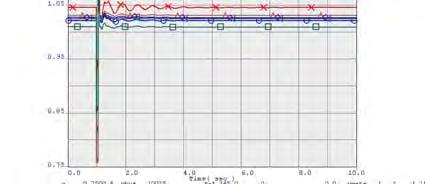
59
60
61
62
63
64
65
66
67
68
69
70

71
72
73
74
75
76
77 Nov 26 to Jan 27 Definitive Interconnection Cluster Window System Impact Study for the Southern Study Cluster 8 MW IA-PNM-26-4 February 28 Prepared by: Utility System Efficiencies, Inc. (USE) Under Contract with: Public Service Company of New Mexico
78 Foreword This technical report is prepared for customer(s) who submitted a Large Generator Interconnection Application to Public Service Company of New Mexico (PNM). This study was performed by Utility System Efficiencies, Inc. (USE) pursuant to a consulting contract with PNM Transmission/Distribution Planning and Contracts Department. Neither USE, PNM, any member of USE, any cosponsor, nor any person acting on behalf of any of them: (a) makes any warranty or representation whatsoever, express or implied, (i) with respect to the use of any information, apparatus, method, process, or similar item disclosed in this document, including merchantability and fitness for a particular purpose, or (ii) that such use does not infringe on or interfere with privately owned rights, including any party's intellectual property, or (iii) that this document is suitable to any particular user's circumstance; or (b) assumes responsibility for any damages or other liability whatsoever (including any consequential damages, even if USE or any USE representative or PNM or any PNM representative has been advised of the possibility of such damages) resulting from your selection or use of this document or any information, apparatus, method, process, or similar item disclosed in this document. Any correspondence concerning this document, including technical and commercial questions should be referred to: Thomas Duane Manager of Transmission Planning Public Service Company of New Mexico 24 Aztec Road NE, MS-Z22 Albuquerque, NM 877
79 Table of Contents Executive Summary... Introduction... 5 NERC Compliance Considerations... 6 Study Criteria... 6 Generator Reactive Power Range Criterion... 7 Voltage Ride-Through Requirement... 7 WECC Over/Under Frequency Standards... 8 Power Flow Criteria... 9 Transient Stability Criteria... Short Circuit Criteria... Power Flow Base Case Development... Project Model Walker Mountain Solar... Generation Dispatch... 3 Power Flow Case Attributes... 4 List of Contingencies... 5 Power Flow Analysis Results Project Configuration Power flow analysis Power Flow Voltage Performance Results Short-Circuit Analysis Results Transient Stability Analysis Results Network Upgrades Cost and Construction Time Estimates Appendix A - Power Flow Diagrams Appendix B Dynamic Modeling Data Appendix C - Transient Stability Plots
80 List of Figures Figure Cluster Project: Definitive Interconnection System Impact Study... Figure 2 IA-PNM-26-4 (NR) Project Illustration... 2 Figure 3 IA-PNM-26-4 (NR) Project and Gen-tie... Figure 4 IA-PNM-26-4 (NR) Project Power Flow Model... 2 Figure 5 Proposed Breaker Configuration of Hidalgo Switching Station List of Tables Table IA-PNM-26-4, Southern Cluster Projects... 2 Table 2 Generator Off-Nominal Frequency Operation Guide... 9 Table 3 Power Flow Disturbance/Performance Criteria... 9 Table 4 PNM Fault Clearing Times... Table 5 Generation Dispatch... 3 Table 6 Power Flow Case Attributes Base Scenario... 4 Table 7 Power Flow Contingencies... 5 Table 8 Transient Stability Contingencies... 2 Table 9 HS Project-triggered Overloads, Percent Loading Table HSP Project-triggered Overloads, Percent Loading... 23

81 Nov 26 to Jan 27 - Definitive Interconnection Cluster Window: Southern Cluster Executive Summary The January 27 Definitive Interconnection Cluster Window had twelve project requests enter the system impact study phase. This Definitive Interconnection System Impact Study ( DISIS ) report identifies the impacts and Network Upgrades associated with the Southern New Mexico cluster developed from the requests submitted to PNM. The Definitive Cluster for the Southern New Mexico area consists of one () request for solar resources, referred to as the Walker Mountain Solar Project, which totals 8 MW gross output and has been assigned queue number IA-PNM The facility will interconnect to the Hidalgo 5 kv bus. The proposed in-service-date is December 3, 29. The customer has requested the project be studied as a Network Resource. The Walker Mountain Solar Project and PNM s surrounding transmission system are shown in Figure below. Figure Cluster Project: Definitive Interconnection System Impact Study The request and proposed Point of Interconnection ( POI ) are summarized below: Page
82 Table IA-PNM-26-4, Southern Cluster Projects Nov 26 to Jan 27 - Definitive Interconnection Cluster Window: Southern Cluster Project Size POI In Service Date IA-PNM MW (Solar) (POI delivery) Type of Interconnection Hidalgo 5 kv 2/3/29 Network Resource (NR) The purpose of this Network Resource study is to identify the Network Upgrades and Interconnection Facilities required to accommodate the full output of IA-PNM The final design and cost estimates of any system reinforcements required for interconnection will be undertaken in a separate facility study, should the customer decide to pursue their Project. El Paso Electric reviewed and commented on this study as an affected system. El Paso operates The Cluster Project and PNM s surrounding transmission system are shown below in Figure 2. Capacities shown below represent what is connected to the transmission system not a particular dispatch. Figure 2 IA-PNM-26-4 (NR) Project Illustration The findings of this DISIS are summarized as follows: Steady-State Performance The power flow analysis shows the following network upgrades are required to accommodate the Network Resource interconnection for IA-PNM-26-4: Page 2
83 Nov 26 to Jan 27 - Definitive Interconnection Cluster Window: Southern Cluster Install a Remedial Action Scheme (RAS) to trip the Project in the event of overload for the P4 contingency of Hidalgo-Turquoise 5 kv and Hidalgo 345/5 kv transformer #. Expand Hidalgo 5 kv switching station from a six breaker ring to an eleven () breaker in breaker and a half configuration. Transient Stability Performance The transient stability analysis had acceptable system performance for all single and double contingencies studied. Ultimately the interconnection customer will have to verify that the Project can meet or exceed PNM interconnection requirements 2. Short Circuit Analysis A short circuit study was conducted to determine if the existing circuit breakers are sufficient to accommodate the increased fault currents associated with project IA-PNM-27-5 in this cluster. Based on these results, the existing circuit breakers are adequate. Reactive Power Analysis The reactive power analysis indicates that IA-PNM-26-4 will need a minimum of MVAr of supplemental reactive power support at the 34.5 kv station transformer bus to achieve a +/-.95 net power factor range at the high side of the Station transformer. This is based on a gross aggregate Project generation of 8. MW (88 MVA) with 8 MW delivered to the POI. The deficiency could be met in full or part with various options including adding additional inverters or installing shunt capacitance. The Interconnection Customer (IC) planned for a 5 MVAr capacitor. For the purposes of the study work, the Project was modeled with one 5 MVAr SVD 3, composed of three segments of 5 MVAr. P4: Fault + Stuck Breaker 2 See PNM FAC--R VOLTAGE LEVEL AND MW/MVAR CAPACITY OR DEMAND 3 SVD = Static VAr Device. Refers to a switched shunt device Page 3
84 Nov 26 to Jan 27 - Definitive Interconnection Cluster Window: Southern Cluster Conclusion The cost estimate and schedule for the Network Upgrades for IA-PNM-26-4 are summarized below: System Upgrade Network Upgrades Required IA-PNM-26-4 Cost ($M) Construction Time Install Remedial Action Scheme.25 8 months Expand Hidalgo 5 kv switching station from a 6 breaker ring to an eleven () breaker in a breaker 6. 8 months and a half configuration Total months Page 4
85 Nov 26 to Jan 27 - Definitive Interconnection Cluster Window: Southern Cluster Introduction This report details the results for the DSIS which determines the physical and electrical impacts to PNM s transmission system of the Southern Cluster. It then identifies any necessary Network Upgrades, certain Customer obligations, and operating procedures to accommodate the interconnection request. The results of this study are based on power flow (thermal and voltage), transient stability (dynamic simulation), and short circuit analysis. This DSIS reviews IA-PNM-26-4 as a Network Resource interconnection as requested by the customer. The purpose of the Network Resource analysis is to identify the Network Upgrades and Interconnection Facilities required to accommodate the full output of IA-PNM Interconnection Service in and of itself does not convey Transmission Service. This DSIS also provides non-binding cost and construction schedule estimates for all identified system reinforcements required for the Network Resource interconnection. Page 5
86 Nov 26 to Jan 27 - Definitive Interconnection Cluster Window: Southern Cluster NERC Compliance Considerations This study will be used as evidence for compliance with North American Electric Reliability Corporation (NERC) standard FAC-2-2 which requires transmission planners and owners, amongst other entities, to study the impact of interconnecting new or materially modified facilities on the Bulk Electric System. The standard addresses the following study requirements for new or modified interconnections:. The reliability impact of the new interconnection, or materially modified existing interconnection, on affected system(s); 2. Adherence to applicable NERC Reliability Standards; regional and Transmission Owner planning criteria; and Facility interconnection requirements; 3. Steady-state, short-circuit, and dynamics studies, as necessary, to evaluate system performance under both normal and contingency conditions; and 4. Study assumptions, system performance, alternatives considered, and coordinated recommendations. While these studies may be performed independently, the results shall be evaluated and coordinated by the entities involved. To address these requirements, the study and associated study report will: Identify the affected systems and reliability impact and the study report will include statements to that effect; Include statements on the applicable NERC Reliability Standards and documentation of other guiding criteria; Identify inclusion of each study type (steady state, dynamic, short circuit) or why a specific category is not included; and Include assumptions, evidence and discussion of system performance, discussion of alternatives or why alternatives are not included and include statements on coordination with other entities documenting the relevant information obtained through coordination. Study Criteria A system reliability evaluation consists of power flow analysis for identifying thermal overloads or voltages outside criteria (too high or low) under normal and contingency conditions. Transient stability analysis is performed to ensure all machines remain in synchronism, all voltage swings are damped, and all frequency dips are within acceptable limits. A short circuit analysis is performed to ensure all fault currents remain within acceptable circuit breaker and switch capabilities. Each evaluation is conducted for credible contingencies that the system might sustain, such as the loss of a single or double circuit line, a transformer, a generator or a combination of these facilities. Planning analysis is conducted sufficiently in advance of potential interconnection, so that network upgrades or modifications can take place in time to prevent a reliability criteria violation. This study was completed in accordance to NERC Standard FAC-2-2. Page 6
87 Nov 26 to Jan 27 - Definitive Interconnection Cluster Window: Southern Cluster Performance of the transmission system is measured against the following planning criteria: the Western Electricity Coordinating Council (WECC) Reliability Criteria, and the North American Electric Reliability Council (NERC) Planning Standards. If system reliability problems resulting from the interconnection of a project are discovered, the study will identify the system facilities or operational measure that will be necessary to mitigate reliability criteria violations. Addition of these new facilities would maintain the reliability to the transmission network. This DSIS investigates whether interconnecting cluster results in: Equipment overloads on transmission lines, transformers, series compensation or other devices Voltage criteria violations All machines remain synchronized to the transmission system Voltage and frequency swings exceed acceptable limits Fault duty increases that result in short circuit current that exceeds the interrupt rating of circuit breakers and switches Generator Reactive Power Range Criterion All generators that seek to interconnect to the PNM transmission system must comply with certain reactive power requirements 4. The required power factor range is determined by the power factor test summarized below: Base cases are constructed with the Southern Cluster generation in-service. The reactive power range at full output and control capability described in the interconnection application are represented in the case with generation enabled. A power flow simulation is conducted to determine whether each generating unit can provide a ±.95 power factor range at the high side of the Station transformer. If a unit cannot provide the ±.95 power factor at the Station transformer, then supplemental reactive power support to achieve a ±.95 power factor range at the Station transformer shall be required. Voltage Ride-Through Requirement Generators connected to the PNM transmission system are required to meet the low voltage ridethrough (LVRT) requirements contained in WECC s PRC-24-WECC-CRT--Low Voltage Ride-Through Criterion 5. In this case, IA-PNM-26-4 is expected to ride through (i) a three-phase fault, cleared in normal time and (ii) a single-line-to-ground fault with delayed clearing at the POI on the Hidalgo to Turquoise 5 kv line. It should be noted that positive-sequence, reduced-order simulation models do not allow for a detailed evaluation of voltage ride-through. The interconnection studies only provide an indication of risk and it 4 See PNM FAC--R VOLTAGE LEVEL AND MW/MVAR CAPACITY OR DEMAND 5 For TPL--., TPL-2-a, TPL-2-b, TPL-3-a, TPL-4- see NERC website Page 7
88 Nov 26 to Jan 27 - Definitive Interconnection Cluster Window: Southern Cluster remains the Interconnection Customer s responsibility to design their generation facilities to meet the ride-through requirement. WECC Over/Under Frequency Standards Generators connected to the PNM transmission system are required to meet the WECC under/over frequency requirements as shown in Table 2 below 6. These requirements should be reviewed with the equipment manufacturer for projects that plan to interconnect to PNM s Transmission system. 6 See PRC-6-WECC-CRT- Attachment A: Off-Nominal Frequency Load Shedding Plan page item 2 Page 8
89 Table 2 Generator Off-Nominal Frequency Operation Guide Under Frequency Limit Over Frequency Limit Minimum Time 5 Nov 26 to Jan 27 - Definitive Interconnection Cluster Window: Southern Cluster >59.4 Hz < 6.6 Hz N/A (continuous operation) 59.4 Hz 6.6 Hz 3 minutes 58.4 Hz 6.6 Hz 3 seconds 57.8 Hz 7.5 seconds 57.3 Hz 45 cycles 57. Hz 6.7 Instantaneous trip 5 Minimum Time is the time the generator should stay interconnected and producing power. Power Flow Criteria All power flow analysis is conducted with version 2._2 of General Electric s PSLF/PSDS/SCSC software. Traditional power flow analysis is used to evaluate thermal and voltage performance of the system under Category P (all elements in service), Category P (N-) and Category P4 and P7 (N-2) conditions. 7 The power flow performance criteria utilized to assess the impact of the interconnecting cluster throughout the DSIS are shown in the table below. The criteria are WECC/NERC performance requirements 8 with applicable additions and/or exceptions for the New Mexico transmission system 9. Table 3 Power Flow Disturbance/Performance Criteria AREA CONDITION LOADING LIMIT EPEC (Area ) PNM (Area ) Tri- State Zone (2-23) VOLTAGE RANGE (p.u.) VOLTAGE DEVIATION APPLICATION Normal ALIS (P) < Normal Rating NA BES facilities P < Emergency Rating % 5 BES facilities P2-P7 < Emergency Rating.9 -. NA BES facilities Normal ALIS (P) < Normal Rating NA BES facilities P < Emergency Rating % BES facilities P2-P7 < Emergency Rating.9 -. NA BES facilities Normal ALIS (P) < Normal Rating NA BES facilities P < Emergency Rating % BES facilities P2-P7 < Emergency Rating.9 -. NA BES facilities ) Taiban Mesa 345, Guadalupe 345 kv, Clines Corners 345 kv, and Jicarilla 345 kv voltages.95 and. pu under normal and contingency conditions 2) PNM will monitor 46 & 69 kv facilities 3) El Paso will monitor 69 kv facilities 4) Greenlee 345 kv is an 8% voltage drop 5) Per /5/ % voltage drop will be use for 345 kv buses 6) Per /5/ EPE will modify its criteria in the 27 FERC 75 filing All equipment loadings must be below their normal ratings under normal conditions. All line loadings must be below their emergency ratings for both single and double contingencies. All transformers and equipment with emergency rating should be below their emergency rating. 7 For TPL-4- see NERC website 8 For TPL--WECC--CR, TPL-2-WECC--CR, TPL-3-WECC--CR, TPL-4-WECC--CR see 9 For PNM exceptions to WECC criteria see Page 9
90 Nov 26 to Jan 27 - Definitive Interconnection Cluster Window: Southern Cluster Transient Stability Criteria The NERC/WECC transient stability performance requirements for transmission contingencies are as follows: All machines will remain in synchronism. All voltage swings will be well damped. Following fault clearing, the voltage shall recover to 8% of the pre-contingency voltage within 2 seconds of the initiating event for all P through P7 events, for each applicable BES bus serving load. Following fault clearing and voltage recovery above 8%, voltage at each applicable BES bus serving load shall neither dip below 7% of pre-contingency voltage for more than 3 cycles nor remain below 8% of pre-contingency voltage for more than two seconds, for all P through P7 events. Fault clearing times are shown in Table 4 Ensure low voltage ride through on all faults. Fault clearing times used in this DISIS are shown in Table 4. Table 4 PNM Fault Clearing Times Categories Fault Type Voltage (kv) 3 Phase Cycles P,P3,P6 Normally Cycles Cleared Cycles Categories Fault Type Voltage (kv) Phase Cycles P2,P5,P7 Normally 23 Cleared Cycles Categories Fault Type Voltage (kv) Phase Cycles P4 Stuck 23 Breaker Cycles Clearing Time (near-far end breakers) Clearing Time (normally opened breaker both near and far end breaker opened due to stuck breaker both near and far end Clearing Time (normally opened breaker both near and far end breaker opened due to stuck breaker both near and far end Short Circuit Criteria Breakers in excess of 92% are flagged for determination as to when the breaker should be considered for upgrading. Generally based on age and maintenance related issues those in excess 95% are to be scheduled for upgrade. Page
91 Nov 26 to Jan 27 - Definitive Interconnection Cluster Window: Southern Cluster Power Flow Base Case Development The approved WECC 27 heavy summer case (27 HS2) was updated with 29 loads and topology to develop the PNM 29 summer peak power flow base case. The corresponding dynamic data file was used. Details of the generation dispatch and resulting path/transmission element flows, and bus voltages of interest are discussed in the "Power Flow Case Attributes" section of this report. The approved WECC 28 heavy spring case (WECC 8HSP2a) was used to develop the PNM 28 offpeak power flow base case. The corresponding dynamic data file was used. Details of the generation dispatch and resulting path/transmission element flows, and bus voltages of interest are discussed in the "Power Flow Case Attributes" section of this report. Project Model Walker Mountain Solar Specific modeling parameters for IA-PNM-26-4 (NR) were provided by the customer in the interconnection application. These parameters were used to construct the power flow and dynamic models. The Project was modeled with 8. MW solar output at the POI (Hidalgo 5 kv bus), resulting in a gross generation of approximately 8. MW at the generator terminals. The Project will connect to the POI through a Generator Step-Up (GSU) transformer, 34.5 kv collector line, 34.5/5 kv station transformer, and a 5 mile gen-tie. The Project modeling includes 5 MVAr of supplemental capacitive reactive power support which is modeled at the low side of the station transformer as one 5 MVAr SVD composed of three 5 MVAr segments. The Project interconnection is depicted in Figure 3 and the power flow model is depicted in Figure 4. Figure 3 IA-PNM-26-4 (NR) Project and Gen-tie Page
 Project Power Flow Model")
92 Nov 26 to Jan 27 - Definitive Interconnection Cluster Window: Southern Cluster Figure 4 IA-PNM-26-4 (NR) Project Power Flow Model Page 2
93 Nov 26 to Jan 27 - Definitive Interconnection Cluster Window: Southern Cluster Generation Dispatch Generation dispatches of existing and planned facilities for each case used for this DSIS are itemized in the table below. It was assumed the Network Resource Project (IA-PNM-26-4) would displace generation at San Juan. Addition of higher-queued generation was dispatched to California. Table 5 Generation Dispatch UNIT NAMEPLATE RATING (S/W) HEAVY SUMMER PRE/POST LIGHT WINTER PRE/POST Coal San Juan Unit San Juan Unit 4 (Area Swing) / /372 Four Corners Unit Four Corners Unit Natural Gas Existing Reeves 43 Existing Reeves 2 44 Existing Reeves 3 66 Existing Delta-Person 32 Existing Luna Energy Facility Existing Lordsburg Existing Pyramid Existing Afton Existing Valencia Energy Facility Existing MPS 4 2 Existing La Luz # Existing Newman Existing Copper 69 Existing Rio Grande Proposed Delta-Person Expansion 95 Proposed La Luz# Proposed Reeves Re-Power Project 6 NM NM San Juan Gas Plant 92 Pmax Wind Resources UNIT NAMEPLATE RATING (S/W) HEAVY SUMMER PRE/POST LIGHT WINTER PRE/POST GROSS/NET DISPATCH LOCATION Existing Taiban Mesa Wind Project Gen Term Existing Aragonne Mesa Wind Project Gen Term Proposed Granada Wind Project 3 NM NM Gen Term Proposed El Cabo Dunmoor Wind Project Gen Term Proposed Taiban Mesa II Project + 5 Gen Term Proposed La Joya/Lucia Wind Project, ER 42 NM NM Gen Term Proposed Broadview/Grady Wind Project (Western Interconnect - Tres Amigas) POI Existing Red Mesa Wind Project Gen Term Existing High Lonesome Mesa Project Gen Term Existing Macho Springs Wind POI Solar Resources Existing Ambrose Solar Project Gen Term Existing Reeves Solar Project Gen Term Existing Los Lunas Solar Project Gen Term Existing Manzano Solar Project Gen Term Existing Marquez Solar Project 7.6 Gen Term If Pre-Project and Post-Project dispatch is the same, only one number is shown. Indicates whether the dispatch is at the gen terminals or at the POI (gross vs net). Page 3
94 Nov 26 to Jan 27 - Definitive Interconnection Cluster Window: Southern Cluster Existing Meadowlake Solar Project Gen Term Existing Prosperity Energy Storage (Studio) Gen Term Solar Project Existing Alta Luna Solar Gen Term Existing Macho Springs Solar Gen Term Existing Hatch PV Gen Term Existing Chaparral PV Gen Term Existing Patriot PV Gen Term Existing Las Cruces PV Gen Term Existing Roadrunner Solar PV Gen Term Proposed Enchanted Mesa Solar Gen Term Proposed Los Morros Solar Project Gen Term Proposed South Valley (South Coors) Solar Gen Term Proposed Lost Horizon Solar Project Gen Term Proposed Lost Horizon 2 Solar Project Gen Term Proposed Lost Horizon 3 Solar Project Gen Term Proposed Tome Solar (VIA) Project Gen Term Proposed Valencia Solar Project POI Proposed Route66 Solar Project POI Proposed Britton Solar Project Gen Term Proposed Rio Puerco Solar Project Gen Term Proposed LA45S (offset by EPE gen) Gen Term Other/Resource Combinations Proposed Torrance Biomass Project Gen Term Proposed Rincon Geothermal Project, ER 38 (Win) 29 (Sum) POI Project Under Study Proposed Walker Project (26-4,NR) POI Terminated Projects (Shown for Reference) Proposed Arabella Solar Project (26-5, ER) 3 NM NM Proposed Aragonne Mesa Solar 4 NM NM (24-3, NR) Proposed El Cabo Wind (ER) 3 NM NM (27-8, ER) Proposed La Sierrita Wind Farm (27-4, ER) 7 NM NM Proposed Mountainair Wind Project NM NM (27-9, ER) *List is preliminary. USE or PNM may suggest changes if warranted. **Energy Resource set to since output will be curtailed if system improvements are required. NM= Not Modeled in this analysis Power Flow Case Attributes Table 6 provides an overview of the power flow cases after loading the project and the generation pattern into the heavy summer and heavy winter cases. Table 6 Power Flow Case Attributes Base Scenario UNIT CASE : PRE-PROJECT HEAVY SUMMER CASE 2: POST-PROJECT (ER) CASE 3: PRE-PROJECT HEAVY SPRING CASE 4: POST-PROJECT (ER) Path 47: Southern New Mexico Path 48: Northern New Mexico Blackwater Converter -5-5 Arroyo Phase-Shifter (Type=4) Gladstone Phase-Shifter (Type=) Page 4
95 Nov 26 to Jan 27 - Definitive Interconnection Cluster Window: Southern Cluster Hidalgo 5/345 kv flow Hidalgo 5 kv PU Bus Voltage Luna 345 kv PU Bus Voltage Key resource related assumptions included: The cases were updated to include the Clines Corners and Broadview/Grady wind projects and the Guadalupe SVC, as well as the Blackwater Synchronous Condenser. The HS swing generator (COULEE) was reduced by shifting area dispatch between Areas 4 and 3. Known Transmission Upgrades and large load additions in Study Area Huning Ranch Data Center Phase 2 modeled Network upgrades associated with LA45S were included: Upgrade Anthony Substation by creating a 345 kv bus and adding a 345/5 kv Transformer. Upgrade Afton North Substation to include an additional 345 kv line Build Afton North-Anthony 345 kv Line (7.4miles) List of Contingencies The contingencies evaluated for power flow (thermal & voltage) in this DSIS are listed below. Table 7 Power Flow Contingencies NO. CATEGORY CONTINGENCY DESCRIPTION Category P Contingencies P All-lines-in service Category P- Contingencies P Generation San Juan Unit 2 P Generation San Juan Unit 4 3 P Generation Argonne Mesa Wind Farm 4 P Generation El Cabo Wind Farm 5 P Generation Elephant Butte (USBR) 6 P Generation High Lonesome Wind Ranch 7 P Generation La Luz 8 P Generation Pyramid Unit and 2 (TSGT) 9 P Generation Pyramid Unit 3 and 4 (TSGT) P Generation Red Mesa Wind Farm P Generation Rio Bravo 2 P Generation Rio Puerco Solar 3 P Generation Route 66 4 P Generation VEF 5 P Generation Springville Unit (TEP) 6 P Generation Springville Unit 2 (TEP) 7 P Generation Springville Unit 3 (TSGT) 8 P Generation Springville Unit 4 (TEP) Page 5
96 Nov 26 to Jan 27 - Definitive Interconnection Cluster Window: Southern Cluster NO. CATEGORY CONTINGENCY DESCRIPTION Category P-2 Contingencies 345 kv 9 P Line Four Corners-Rio Puerco 345 kv 2 P Line Four Corners-San Juan 345 kv 2 P Line Four Corners-Shiprock 345 kv 22 P Line Luna-Macho Springs 345 kv 23 P Line Luna-Diablo 345 kv 24 P Line Luna-LEF 345 kv 25 P Line BA-Rio Puerco 345 kv ck 26 P Line BA-Rio Puerco 345 kv ck 2 27 P Line BA-Norton 345 kv 28 P Line B-A - BA kv ckt 29 P Line B-A - BA kv ckt 2 3 P Line B-A - Clines Corners 345 kv 3 P Line Guadalupe-Clines Corners 345 kv 32 P Line Guadalupe-Taiban Mesa 345 kv 33 P Line Taiban Mesa-Blackwater 345 kv 34 P Line Ojo-Jicarilla 345 kv 35 P Line Ojo-Taos 345 kv 36 P Line San Juan-Ship Rock 345 kv and San Juan 345/23 kv Transformer 37 P Line San Juan-Ship Rock 345 kv 38 P Line San Juan-McKinley 345 kv ck 39 P Line San Juan-McKinley 345 kv ck 2 4 P Line San Juan-Water Flow 345 kv 4 P Line San Juan-Coal Mine 23 kv 42 P Line Cabezon-San Juan 345 kv 43 P Line Rio Puerco-Cabezon 345 kv 44 P Line Jicarilla-San Juan 345 kv 45 P Line West Mesa-Arroyo 345 kv 46 P Line Sandia-West Mesa 345 kv 47 P Line Rio Puerco-West Mesa 345 kv 48 P Line Rio Puerco-West Mesa #2 345 kv 49 P Line CALIENTE AMRAD 345. Circuit 5 P Line CALIENTE PICANTE 345. Circuit 5 P Line CALIENTE PICANTE 345. Circuit 2 52 P Line MACHOSPG MACHOSPRNGHV 345. Circuit 53 P Line MACHOSPG SPRINGR 345. Circuit 54 P Line HIDALGO GREENLEE 345. Circuit 55 P Line LUNA AFTON 345. Circuit Line LUNA BLAK_MTN 345. Circuit 56 P Line LUNA 345. LA45S 345. Circuit 57 P Line LA45S 345. AFTON_N 345. Circuit 58 P Line NEWMAN - ARROYO 345. Circuit 59 P Line NEWMAN - AFTON_N 345. Circuit 6 P Line PICANTE - NEWMAN 345. Circuit 6 P Line Greenlee-Winchester 345 kv 62 P Line Greenlee-Willow 345 kv 63 P Line Willow-Winchester 345 kv 64 P Line Greenlee-Greenlee AEPCO 345 kv (TEP) 65 P Line Greenlee-Copper Verde 345 kv (TEP) 66 P Line Greenlee-Springville 345 kv (TEP) 67 P Line Springville-Vail 345 kv 68 P Line Springville-Coronado 345 kv 69 P Line Luna Hidalgo 345 kv 7 P Line Afton Afton North(Black Mountain) 345kV 7 P Line Afton Diablo 345kV Page 6
97 Nov 26 to Jan 27 - Definitive Interconnection Cluster Window: Southern Cluster NO. CATEGORY CONTINGENCY DESCRIPTION 72 P Afton_N-Anthony 345 kv Category P-3 Contingencies 345 kv 73 P Transformer Anthony 345/5 kv 74 P Transformer BA 345/5 kv 75 P Transformer HIDALGO 345/5 kv # 76 P Transformer HIDALGO 345/5 kv #2 77 P Transformer Jicarilla 345/5 kv 78 P Transformer Luna 345/5 kv 79 P Transformer NEWMAN 345/5 kv 8 P Transformer Ojo 345/5 kv 8 P Transformer RIO PUERCO 345/5 kv 82 P Transformer Sandia 345/5 kv 83 P Transformer Cabezon/Torreon 345/5 kv 84 P Transformer West Mesa 345/5 kv # 85 P Transformer West Mesa 345/5 kv #2 86 P Transformer ARROYO 345/5 kv 87 P Transformer CALIENTE345/5 kv 88 P Transformer DIABLO 345/5 kv 89 P Transformer AFTON_N 345/5 kv 9 P Transformer PICANTE 345/5 kv 9 P Transformer AMRAD 345/5 kv Category P-2 Contingencies 5 kv 92 P Line Alamogordo-Amrad 5 kv 93 P Line Alamogordo-Holloman 5 kv 94 P Line Amrad-Oro Grande 5 kv 95 P Line Sandia 2 Radial 5 kv (Non-BES) 96 P Line Ambrosia-Yah-Ta-Hey 5 kv 97 P Line Ambrosia-Red Mesa 5 kv 98 P Line Ambrosia-Bluewater 5 kv 99 P Line Valencia-Springer 5 kv P Line Valencia-Zia 5 kv P Line Prager-West Mesa 2 5 kv 2 P Line BA-Reeves 2 5 kv 3 P Line BA-Zia 5 kv 4 P Line BA-Reeves 5 kv 5 P Line Pachmann-Scenic 5 kv 6 P line Person Tome 5 kv PB 7 P Line Corrales Bluff-Irving 5 kv 8 P Line Corrales Bluff-Pachmann 5 kv 9 P Line Corrales Bluff-Veranda 5 kv P Line Corrales Bluff-Sara, 2, 6, and 7 5 kv (Non-BES) P Line Corrales Bluff-Sara 3,4, and 5 5 kv (Non-BES) 2 P Line West Mesa -Snow Vista 5 kv 3 P Line Person Radial 5 kv (Non-BES) 4 P Line Embudo-Sandia 5 kv 5 P Line College-El Cerro 5 kv 6 P Line Tome-College 5 kv 7 P Line Embudo-Juan Tabo 5 kv (Non-BES) 8 P Line Embudo-Reeves 2 5 kv 9 P Line Embudo-Reeves 5 kv 2 P Line Mimbres-Hondale 5 kv (Radial) 2 P Line Mimbres-Deming 5 kv (Radial) 22 P Line Mimbres-Picacho 5 kv 23 P Line Embudo-North 5 kv 24 P Line Irving-Reeves 5 kv Page 7
98 Nov 26 to Jan 27 - Definitive Interconnection Cluster Window: Southern Cluster NO. CATEGORY CONTINGENCY DESCRIPTION 25 P Line Person - La Ladera 5 kv AT 26 P Line LaLadera-El_Cerro 5 kv AT 27 P Line KAFB-Person 5 kv 28 P Line Luna-Mimbres 5 kv 29 P Line Reeves 2-West Mesa 2 5 kv 3 P Line Red Mesa-West Mesa 5 kv 3 P Line Norton-Zia 5 kv 32 P Line Mimbres - ALTA LUNA 5 kv 33 P Line Algodones-Norton/Zia 5 kv 34 P Line Norton-Hernandez 5 kv 35 P Line Norton-ETA 5 kv 36 P Line Person-West Mesa 2 5 kv 37 P Line Person-Snow Vista 5 kv 38 P Line North - Richmond 5 kv 39 P Line Prager-Richmond 5 kv 4 P Line Sandia-Richmond 5 kv 4 P Line Prager-Lomas 5 kv (Non-BES) 42 P Line North-Reeves 5 kv 43 P Line Reeves 2-Mission 5 kv 44 P Line KAFB-Sandia 5 kv 45 P Line Sandia-KAFB Load 5 kv 46 P Line Belen-Tome 5 kv 47 P Line Irving-West Mesa 5 kv 48 P Line Huning Ranch-West Mesa 5 kv 49 P Line Huning Ranch-West Mesa 3 5 kv 5 P Line Los Morros-Huning Ranch 5 kv 5 P Line Yah-Ta-Hey-Coalmine/Windowrock 5 kv 52 P Line Yah-Ta-Hey-Pitt Midway 5 kv (Non-BES) 53 P Line BA-Pachmann 5 kv 54 P Line Pachamann-Rio Puerco 5 kv 55 P Line Algodones-Pachmann 5 kv 56 P Line Rio Puerco-Veranda 5 kv 57 P Line Alamogordo-TSGT Otero Sub 5 kv 58 P Line Algodones-Torreon 5 kv 59 P Line Belen-Willard 5 kv 6 P Line Belen-Socorro (TSGT) 5 kv 6 P Route 66 - Bluewater 5 kv line 62 P Line West Mesa 3 - Route66 kv 63 P Line Bluewater-PEGS 5 kv (TSGT) 64 P Line Caballo - ALTA LUNA 5 kv 65 P Line Yah-Ta-Hey-PEGS (TSGT) 5 kv 66 P Line Clapham-Rosebud 5 kv (TSGT) 67 P Line Alamogordo-Dona Ana 5 kv 68 P Line Picacho-Dona Ana 5 kv 69 P Line Elephant Butte-Caballo 5 kv (TSGT) 7 P Line Elephant Butte-Frontier 5 kv (TSGT) 7 P Line Taos-Hernandez 5 kv (TSGT) 72 P Line Torreon-La Jara 5 kv Line (TSGT) 73 P Line PEGS-MPC 5 kv (TSGT) 74 P Line Ojo-Hernandez 5 kv 75 P Line Picacho-Frontier 5 kv 76 P Line Pyramid-Playas 5 kv (TSGT) 77 P Line Elephant Butte-Socorro 5 kv (TSGT) 78 P Line Springer-Gladstone 5 kv (TSGT) 79 P Line Springer-York Canyon 5 kv (TSGT) Page 8
99 Nov 26 to Jan 27 - Definitive Interconnection Cluster Window: Southern Cluster NO. CATEGORY CONTINGENCY DESCRIPTION 8 P Line West Mesa 3-Scenic 5 kv 8 P Line Britton-Willard 5 kv 82 P Line Willard-Duran 5 kv (TSGT Non-BES) 83 P Line Carrizo Canyon-Alamogordo kv (TSGT Non-BES) 84 P Line Carrizo Canyon-Gavilan 5 kv (TSGT Non-BES) 85 P Line Luna-MD 5 kv 86 P Line MD-Turquoise 5 kv 87 P Line MD-Ivanhoe 5 kv 88 P Line Hidalgo-Pyramid # 5 kv 89 P Line Hidalgo-Lordsburg 5 kv 9 P Line Hidalgo-Turquoise 5 kv 9 P Line Turquoise-Tyrone 5 kv 92 P Line Belen-Los Morros 5 kv 93 P Line North-Mission 5 kv 94 P Line Algodones-Britton 5 kv 95 P Line BRITTON_PNM 5. to BRITTON_SOL 5. Circuit 96 P Line AFTON_N - AIRPOR 5 kv 97 P Line HATCH - JORNADA 5 kv 98 P Line LE - JORNADA 5 kv 99 P Line JORNADA - ARROYO 5 kv 2 P Line ANTHONY - ARROYO 5 kv (OOS in case) 2 P Line ANTHONY - BORDER 5 kv 22 P Line ANTHONY - NEWMAN 5 kv 23 P Line ANTHONY - SALOPEK 5 kv 24 P Line ANTHONY - TRANSMTN 5 kv 25 P Line ARROYO - COX 5 kv 26 P Line ARROYO - TALAVERA 5 kv 27 P Line MPS - COYOTE 5 kv 28 P Line MPS - MONTWOOD 5 kv 29 P Line CALIENTE - MPS 5 kv # 2 P Line CALIENTE - MPS 5 kv #2 2 P Line CALIENTE - MPS 5 kv #3 22 P Line HATCH - LEASBURG 5 kv (OOS in case) 23 P Line HOLLOMAN - LARGO 5 kv 24 P Line LAS_CRUC - ARROYO 5 kv 25 P Line LAS_CRUC - SALOPEK 5 kv 26 P Line MAR - LARGO 5 kv 27 P Line WHITE_SA - ALA_5 5 kv 28 P Line LEASBURG - JORNADA 5 kv (OOS in case) 29 P Line AFTON_N - AIRPOR 5 kv 22 P Line TALAVERA - SALOPEK 5 kv 22 P Line MINER - CROMO 5 kv Line PATRIOT - CROMO 5 kv Category P-2 Contingencies 69 kv 222 P Line Lordsburg-MD 69 kv (Non BES) 223 P Line Lordsburg-Burro Mountain 69 kv (Non BES) 224 P Line MD-Silver City 69 kv Line (Non BES) 225 P Line Silver City-Turquoise 69 kv (Non BES) 226 P Line Silver City-North Silver 69 kv Line (Non BES) 227 P Line Turquoise-Burro Mountain 69 kv (Non BES) (OOS in case) Category P-3 Contingencies 5 kv and 69 kv 228 P Transformer Lordsburg 5/69 kv 229 P Transformer MD 5/69 kv 23 P Transformer Person 5/46 kv (Non-BES) 23 P Transformer Sara Rd 8 (Non-BES) Page 9
100 Nov 26 to Jan 27 - Definitive Interconnection Cluster Window: Southern Cluster NO. CATEGORY CONTINGENCY DESCRIPTION 232 P Transformer Turquoise 5/69 kv 233 P Transformer MD 69/23 kv Distribution Transformers (Non BES) 234 P Transformer Silver City 69/2 kv # (Non BES) 235 P Transformer Silver City 69/2 kv #2 (Non BES) 236 P Transformer Valencia 5/46 kv (Non-BES) Category P-4 Contingencies 237 P SVC Guadalupe 238 P Capacitor Britton 5 kv 239 P Capacitor Silver City 69 kv (Non BES) Category P Project Contingencies 24 P Walker Mountain Solar Category P2 Contingencies 24 P2-2 Willard Substation (TSGT Non-BES) 242 P2-4 Bus Tie Sandia 5 kv 243 P2-4 Bus Tie West Mesa -West Mesa 2 5 kv 244 P2-4 Bus Tie West Mesa -West Mesa 3 5 kv Category P4 & P7 Contingencies (P4=Fault + Stuck Breaker, P7 = Common Structure)) 245 P4 Walker Mountain Solar & Pyramid line 2 transformer (post project only) 246 P4 Turquoise & Hidalgo #2 transformer (pre-project only) 247 P4 Turquoise & Hidalgo # transformer 248 P4 Pyramid line 2 & Hidalgo # transformer (pre-project only) 249 P4 Pyramid line 2 & Lordsburg 5 kv lines (pre-project only) 25 P4 Lordsburg and Pyramid line 5 kv lines 25 P4 Pyramid line & Hidalgo #2 (pre-project only) 252 P4 Afton-Luna 345 kv Line and Afton Steam Unit 253 P4 Luna 345/5 kv Transformer and Luna-Hidalgo 345 kv Line Page 2
101 Nov 26 to Jan 27 - Definitive Interconnection Cluster Window: Southern Cluster The contingencies evaluated for transient stability in this DSIS are listed below. Table 8 Transient Stability Contingencies Disturbance Cat* Fault Location Fault Type No disturbance flat run P N/A N/A 4 Luna Mimbres 5 kv line P Luna 5 3ph 4 2 Greenlee Hidalgo 345 P Greenlee 345 3ph 4 3 Springerville Macho Springs 345 P Macho Springs 345 3ph 4 4 West Mesa Arroyo 345 kv line P West Mesa 345 3ph 4 5 Afton Newman 345 kv line P Newman 345 kv 3ph 4 6 Hidalgo - Turquoise 5 kv line P Hidalgo 5 kv 3ph 4 Clearing Time 7 Hidalgo - Turquoise 5 kv line P Hidalgo 5 kv ph 6 8 Hidalgo 345/5 kv Transformer P Hidalgo 345 kv 3ph 4 Breaker Failure Disturbances Cat* Fault Location Fault Type Clearing Time 8 9 Hidalgo - Walker Mountain Solar & Hidalgo - Pyramid line 2 5 kv Hidalgo-Lordsburg and Hidalgo-Pyramid line 5 kv P4 Hidalgo 5 kv ph 4-6 P4 Hidalgo 5 kv ph 4-6 Reactive Power Analysis Each Project was tested in the over-excited and under-excited direction and the required reactive power requirement was enforced at the POI. Walker Mountain Solar: IA-PNM-26-4 (NR) The reactive power analysis indicates that IA-PNM-26-4 will need a minimum of MVAr of supplemental reactive power support at the 34.5 kv station transformer bus to achieve a +/-.95 net power factor range at the high side of the Station transformer. This is based on a gross aggregate Project generation of 8. MW (88 MVA) with 8 MW delivered to the POI. The deficiency could be met in full or part with various options including adding additional inverters or installing shunt capacitance. The Interconnection Customer (IC) planned for a 5 MVAr capacitor. For the purposes of the study work, the Project was modeled with one 5 MVAr SVD 2, composed of three segments of 5 MVAr. 2 SVD = Static VAr Device. Refers to a switched shunt device Page 2
102 Nov 26 to Jan 27 - Definitive Interconnection Cluster Window: Southern Cluster Power Flow Analysis Results This section describes the individual project performance from the inverters to the point of interconnection as well as identifying network upgrades associated with the projects as a cluster. Project Configuration Walker Mountain Solar: IA-PNM-26-4 (NR) The study modeled the interconnection of the Network Resource project, Walker Mountain Solar, to the Hidalgo 5 kv substation. The Project was dispatched at 8. MW resulting in a net dispatch of 8 MW at the POI. Heavy Summer: Walker Mountain Solar: One 5 MVAr SVD (composed of 3@ 5 MVAr segments) modeled at the 34.5 kv bus of the station transformer with SVD bus voltage schedule set to.3. Station transformer set at the fixed center tap position. Generator voltage schedule set to.3 to achieve ~ unity pf at the equivalent generator, and resulting in Project pf at the POI of.995. Heavy Spring: Walker Mountain Solar: One 5 MVAr SVD (composed of 3@ 5 MVAr segments) modeled at the 34.5 kv bus of the station transformer with SVD bus voltage schedule set to.3. Station transformer set at the fixed center tap position. Generator voltage schedule set to.3 to achieve ~ unity pf at the equivalent generator, and resulting in Project pf at the POI of.995. Power flow analysis All two hundred fifty-three (253) outages were simulated in the Heavy Summer and Heavy Spring cases. The post-project cases included Walker Mountain Solar Project at full output. Heavy Summer Thermal Analysis The thermal results showed the Project did not trigger any single contingency overloads in the Heavy Summer cases. The Project did trigger an overload on the Hidalgo 345/5 kv transformer #2 for the P4 (fault + stuck breaker) contingency resulting in loss of both Hidalgo-Turquoise 5 kv and Hidalgo 345/5 kv transformer #. This issue will be mitigated with a RAS to trip Project generation. Table 9 HS Project-triggered Overloads, Percent Loading # BRANCH/ELEMENT CONTINGENCY HS PRE HS POST COMMENTS P4 CONTINGENCIES Hidalgo 345/5 kv Xfmr #2 Turquoise-Hidalgo 5 kv and Hidalgo 345/5 Xfmr. Open MD-IVANHOE Turquoise-Hidalgo 5 kv and Hidalgo 345/5 Xfmr. Trip PDTyrone RAS: Trip Project Generation Page 22
103 Nov 26 to Jan 27 - Definitive Interconnection Cluster Window: Southern Cluster Non-Peak Thermal Analysis The thermal results showed the Project did not trigger any single contingency overloads in the Heavy Spring cases. The Project did trigger an overload on the Hidalgo 345/5 kv transformer #2 for the P4 (fault + stuck breaker) contingency resulting in loss of both Hidalgo-Turquoise 5 kv and Hidalgo 345/5 kv transformer #. This issue will be mitigated with a RAS to trip Project generation. Table HSP Project-triggered Overloads, Percent Loading # BRANCH/ELEMENT CONTINGENCY HSP PRE HSP POST COMMENTS P4 CONTINGENCIES Hidalgo 345/5 kv Xfmr #2 Turquoise-Hidalgo 5 kv and Hidalgo 345/5 Xfmr. Open MD-IVANHOE Turquoise-Hidalgo 5 kv and Hidalgo 345/5 Xfmr. Trip PDTyrone RAS: Trip Project Generation Power Flow Voltage Performance Results The voltage analysis focused on Areas,, and 4, and on voltages 46 kv and above. Review of the voltage results did not identify any Cluster generated violations. Short-Circuit Analysis Results A short circuit study was conducted to determine if the existing circuit breakers are sufficient to accommodate the increased fault currents associated with project IA-PNM-27-5 in this cluster. Based on these results, the existing circuit breakers are adequate. Transient Stability Analysis Results The transient stability analysis had acceptable system performance for all single (P) and double (P4 & P7) contingencies studied. Ultimately the interconnection customer will have to verify that the project can meet or exceed PNM interconnection requirements. Modifications were made to the Project supplied lhfrt model for this analysis to ensure frequency ridethough capability. Further details are provided in the Dynamic Modeling Appendix. The IC will need to verify Project values and capability, and it is up to the IC to ensure that their proposed project will in fact ride through and stay on line during disturbances to meet criteria.. dttrip changed from to.2 2. dttrip2 changed from to.2 See Appendix for plots. Page 23
104 Nov 26 to Jan 27 - Definitive Interconnection Cluster Window: Southern Cluster Network Upgrades The power flow analysis shows the following network upgrades are required to accommodate the Network Resource interconnection for IA-PNM-26-4: Install a Remedial Action Scheme (RAS) to trip the Project in the event of overload for the P4 contingency of Hidalgo-Turquoise 5 kv and Hidalgo 345/5 kv transformer #. Expand Hidalgo 5 kv switching station from a six breaker ring to an eleven () breaker in breaker and a half configuration. Figure 5 Proposed Breaker Configuration of Hidalgo Switching Station Cost and Construction Time Estimates The cost estimate and schedule for the Network Upgrades for the Southern Cluster are summarized below: System Upgrade Network Upgrades Required IA-PNM-26-4 Cost ($M) Construction Time Install Remedial Action Scheme.25 8 months Expand Hidalgo 5 kv switching station from a 6 breaker ring to an eleven () breaker in a breaker 6. 8 months and a half configuration Total months Page 24
105 Appendix A Power Flow Plots Nov 26 to Jan 27 - Definitive Interconnection Cluster Window: Southern Cluster
106 Nov 26 to Jan 27 - Definitive Interconnection Cluster Window: Southern Cluster This page left intentionally blank.
107 IA-PNM HS, Pre-Project P BELEN_PG TYRONE SILVER_C MD b MD b IVANHOE HOT_SPRG EL_BUTTE GAVILAN RUIDOSO C_CANYON LORDSBRG LORDSBRG 32 4 G RAZERGEN To Greenlee TURQTAP BURROMTN PLAYAS N.O. HIDALGO PLAYAS PDPLAYAS TURQUOIS TURQUOIS HIDALGO PYRTAP LEF PDTYRONE To Springerville PYRAMID LUNA HURLEY_# LUNA DEMTAP LA45S_POI CHINO MIMBRES DIABLO CABALLOT b b2 b ALTLUNTP S AFTON AIRPOR_T AFTON_N AFTON_N FRNTIER AIRPOR ANTHONY ANTHONY PICACHO JORNADA To Hatch DONA_ANA LAS_CRUC ARROYO Note: Future cases have mutiple lines from Jornada to Arroyo.. To West Mesa ARROYO NEWMAN BLAZER_T ALAMOGCP To Salopek HOLLOMAN AMRAD AMRAD_B AMRAD General Electric International, Inc. PSLF Program Fri Oct 27 3:33:22 27 _9HS_Walker_Pre_swg.sav IA-PNM-26-4 Walker Mountain 8 MW Solar Pre-Project case 9HS MW/MVAR snm_new_27d Rating =
108 IA-PNM HS, Post-Project P BELEN_PG TYRONE SILVER_C MD b MD b IVANHOE HOT_SPRG EL_BUTTE GAVILAN RUIDOSO C_CANYON LORDSBRG LORDSBRG 32 DSIS 8S: Walker G RAZERGEN To Greenlee TURQTAP BURROMTN PLAYAS N.O. HIDALGO PLAYAS PDPLAYAS v TURQUOIS TURQUOIS SPVHDLG_TIE HIDALGO PYRTAP LEF PDTYRONE To Springerville PYRAMID LUNA HURLEY_# LUNA DEMTAP LA45S_POI 45 2 CHINO MIMBRES DIABLO CABALLOT b b2 b ALTLUNTP S AFTON AIRPOR_T AFTON_N AFTON_N FRNTIER AIRPOR ANTHONY ANTHONY PICACHO JORNADA To Hatch DONA_ANA LAS_CRUC ARROYO Note: Future cases have mutiple lines from Jornada to Arroyo.. To West Mesa ARROYO NEWMAN BLAZER_T ALAMOGCP To Salopek HOLLOMAN AMRAD AMRAD_B AMRAD General Electric International, Inc. PSLF Program Fri Oct 27 3:42:9 27 2_9HS_Walker_Post_swg2.sav IA-PNM-26-4 Walker Mountain 8 MW Solar Post-Project case 9HS MW/MVAR Rating =
109 IA-PNM HSP, Pre-Project P BELEN_PG TYRONE SILVER_C MD b MD b IVANHOE HOT_SPRG EL_BUTTE GAVILAN RUIDOSO C_CANYON LORDSBRG LORDSBRG 32 4 G RAZERGEN To Greenlee TURQTAP BURROMTN PLAYAS HIDALGO PLAYAS PDPLAYAS N.O TURQUOIS TURQUOIS HIDALGO PYRTAP LEF PDTYRONE To Springerville PYRAMID LUNA HURLEY_# LUNA DEMTAP LA45S_POI 45 7 CHINO MIMBRES DIABLO CABALLOT b b2 b ALTLUNTP S 5 26 AFTON AIRPOR_T AFTON_N AFTON_N FRNTIER AIRPOR ANTHONY ANTHONY PICACHO JORNADA To Hatch DONA_ANA LAS_CRUC ARROYO Note: Future cases have mutiple lines from Jornada to Arroyo.. To West Mesa ARROYO NEWMAN BLAZER_T ALAMOGCP To Salopek HOLLOMAN AMRAD AMRAD_B AMRAD General Electric International, Inc. PSLF Program Fri Oct 27 3:34:2 27 3_8HSP_Walker_Pre.sav IA-PNM-26-4 Walker Mountain 8 MW Solar Pre-Project case 9HS MW/MVAR snm_new_27d Rating =
110 IA-PNM HSP, Post-Project P BELEN_PG TYRONE SILVER_C MD b MD b IVANHOE HOT_SPRG EL_BUTTE GAVILAN RUIDOSO C_CANYON LORDSBRG LORDSBRG 32 DSIS 8S: Walker G RAZERGEN To Greenlee TURQTAP BURROMTN PLAYAS N.O. HIDALGO PLAYAS PDPLAYAS v TURQUOIS TURQUOIS SPVHDLG_TIE HIDALGO PYRTAP LEF PDTYRONE To Springerville PYRAMID LUNA HURLEY_# LUNA DEMTAP LA45S_POI 45 CHINO MIMBRES DIABLO CABALLOT b b2 b ALTLUNTP S 5 26 AFTON AIRPOR_T AFTON_N AFTON_N FRNTIER AIRPOR ANTHONY ANTHONY PICACHO JORNADA To Hatch DONA_ANA LAS_CRUC ARROYO Note: Future cases have mutiple lines from Jornada to Arroyo.. To West Mesa ARROYO NEWMAN BLAZER_T ALAMOGCP To Salopek HOLLOMAN AMRAD AMRAD_B AMRAD General Electric International, Inc. PSLF Program Fri Oct 27 3:42:4 27 4_8HSP_Walker_Post2.sav IA-PNM-26-4 Walker Mountain 8 MW Solar Post-Project case 9HS MW/MVAR Rating =

111 Nov 26 to Jan 27 - Definitive Interconnection Cluster Window: Southern Cluster Appendix B Dynamic Modeling Data This appendix documents the dynamic model parameters provided by the IC and used in the study. During the analysis, initial results showed the Project was tripping due to the LHFRT dvttrp/dttrp and dvttrp4/dttrp4 settings. Modifications were made to the Project supplied lhfrt model for this analysis to ensure frequency ride-though capability. The IC will need to verify Project values and capability, and it is up to the IC to ensure that their proposed project will in fact ride through and stay on line during disturbances to meet criteria. The dttrp value of. seconds and the dttrp4 value of. seconds were both increased to.2 seconds, and the units stayed online. EXTRACTED from WECC Solar Plant Dynamic Modeling Guidelines 4/24 regc_a: Generator/converter model Variable Project Data PSLF Default MVA Base ORIGINAL DATA: 88 Description Lvplsw Connect () / disconnect () Low Volt. Power Logic switch Rrpwr LVPL ramp rate limit, p.u. Brkpt.85.9 LVPL characteristic breakpoint, p.u. Zerox.8.5 LVPL characteristic zero crossing, p.u. Lvpl.22 LVPL breakpoint, p.u. Vtmax Voltage limit used in the high voltage reactive power logic,.2 2 p.u. Lvpnt..8 High voltage point for low voltage active power logic, p.u. Lvpnt.4 Low voltage point for low voltage active power logic, p.u. Qmin Limit in the high voltage reactive power logic, p.u. Accel.7 Acceleration factor used in the high voltage reactive power logic, p.u. Tg..2 Time constant, sec. Tfltr.2.2 Voltage measurement time constant, sec. Iqrmax Upward rate limit on reactive current command p.u./sec See Note m. Iqrmin -99 Downward rate limit on reactive current command p.u./sec See Note m. Xe Generator effective reactance, p.u. See Note n.
 vdip.85-99.99 Vterm < vdip activates the current injection logic, p.u. (see Note b) vup.5 99.99 Vterm > vup activates the current injection logic, p.u. (see Note b) trv.2.")
112 Nov 26 to Jan 27 - Definitive Interconnection Cluster Window: Southern Cluster reec_b: Renewable energy electrical control model Variable Project Data PSLF Default Description mvab MVA base (See Note a) vdip Vterm < vdip activates the current injection logic, p.u. (see Note b) vup Vterm > vup activates the current injection logic, p.u. (see Note b) trv.2.5 Transducer time constant, sec. dbd -.5. Deadband in voltage error, p.u. dbd2.5. Deadband in voltage error, p.u. kqv 5. Reactive current injection gain, p.u./p.u. iqh.5 Maximum limit of reactive current injection (iqinj), p.u. iql Minimum limit of reactive current injection (iqinj), p.u. vref. Reference voltage (See Note c) tp.2.5 Electrical power transducer time constant, sec. qmax Reactive power maximum limit, p.u. qmin Reactive power minimum limit, p.u. vmax.. Voltage control maximum limit, p.u. vmin.9.9 Voltage control minimum limit, p.u. kqp 2. Proportional gain, p.u. kqi. Integral gain, p.u. kvp 5. Proportional gain, p.u. kvi 6. Integral gain, p.u. tiq.5.5 Time constant, sec. dpmax Up ramp rate on power reference p.u./sec. dpmin Down ramp rate on power reference p.u./sec. pmax. Maximum power reference, p.u. pmin. Minimum power reference, p.u. imax.4.25 Maximum allowable total current limit, p.u. tpord. Time constant, sec. pfflag Power factor flag: : Power factor control : Q control vflag Voltage control flag: : Q Control : Voltage control qflag Reactive power control flag : Voltage/Q control : Constant power factor or Q Control pqflag Flag for P or Q priority selection on current limit: : P priority : Q priority EXTRACTED from WECC Solar Plant Dynamic Modeling Guidelines 4/24
113 Nov 26 to Jan 27 - Definitive Interconnection Cluster Window: Southern Cluster lhvrt: Low/High Voltage Ride Through generator protection Variable Project Data PSLF Default Description vref dvtrp.4. Delta voltage trip level, p.u. (4%) dvtrp2.5. Delta voltage trip level, p.u. (5%) dvtrp Delta voltage trip level, p.u. (5%) dvtrp Delta voltage trip level, p.u. (%) dvtrp5. Delta voltage trip level, p.u. dvtrp6. Delta voltage trip level, p.u. dvtrp7. Delta voltage trip level, p.u. dvtrp8. Delta voltage trip level, p.u. dvtrp9. Delta voltage trip level, p.u. dvtrp. Delta voltage trip level, p.u. dttrp. Voltage trip time, sec. dttrp2 3. Voltage trip time, sec. dttrp3.9. Voltage trip time, sec. dttrp4.6. Voltage trip time, sec. dttrp5. Voltage trip time, sec. dttrp6. Voltage trip time, sec. dttrp7. Voltage trip time, sec. dttrp8. Voltage trip time, sec. dttrp9. Voltage trip time, sec. dttrp. Voltage trip time, sec. alarm. If greater than zero, no tripping action is enforced; a message is printed when a trip level is exceeded. lhfrt: Low/High Frequency Ride Through generator protection Variable Project Data PSLF Default Description fref 6 Delta frequency is computed with respect to fref dftrp 2.5. Delta frequency trip level, p.u. (62.5 Hz) dftrp2.5. Delta frequency trip level, p.u. (6.5 Hz) dftrp Delta frequency trip level, p.u. (57.5 Hz) dftrp Delta frequency trip level, p.u. (56.5 Hz) dftrp5. Delta frequency trip level, p.u. dftrp6. Delta frequency trip level, p.u. dftrp7. Delta frequency trip level, p.u. dftrp8. Delta frequency trip level, p.u. dftrp9. Delta frequency trip level, p.u. dftrp. Delta frequency trip level, p.u. Original:. Frequency trip time, sec. dttrp. trips Change to.2 dttrp2 3. Frequency trip time, sec. dttrp3. Frequency trip time, sec. Original:. Frequency trip time, sec. dttrp4. trips Change to.2 dttrp5. Frequency trip time, sec. dttrp6. Frequency trip time, sec. dttrp7. Frequency trip time, sec. dttrp8. Frequency trip time, sec. dttrp9. Frequency trip time, sec. dttrp. Frequency trip time, sec. alarm If greater than zero, no tripping action is enforced; a
114 Nov 26 to Jan 27 - Definitive Interconnection Cluster Window: Southern Cluster message is printed when a trip level is exceeded. Notes: ) trip times > 3 sec are not modeled. 2) Instantaneous trips are initially modeled with a minimum trip time of.5 sec to avoid nuisance trips.
115 Nov 26 to Jan 27 - Definitive Interconnection Cluster Window: Southern Cluster Appendix C Transient Stability Plots This appendix provides a sample of the transient stability plots run as part of this study. Additional plots may be provided on request. The plots represent the HS post-project case with project dispatched. Plots for the following contingencies are provided: Disturbance Cat* Fault Location Fault Type Clearing Time (cycles) Category P Contingencies No disturbance flat run P N/A N/A 4 Category P Contingencies No disturbance flat run P N/A N/A 4 2 Luna Mimbres 5 kv line P Luna 5 3ph 4 3 Greenlee Hidalgo 345 P Greenlee 345 3ph 4 4 Springerville Macho Springs 345 P Macho Springs 345 3ph 4 5 West Mesa Arroyo 345 kv line P West Mesa 345 3ph 4 6 Afton Newman 345 kv line P Newman 345 kv 3ph 4 7 Hidalgo - Turquoise 5 kv line P Hidalgo 5 kv 3ph 4 8 Hidalgo - Turquoise 5 kv line P Hidalgo 5 kv ph 6 Category P4 Contingencies 9 Hidalgo - Walker Mountain Solar & Hidalgo - Pyramid line 2 5 kv P4 Hidalgo 5 kv ph 4-6 Hidalgo-Lordsburg and Hidalgo-Pyramid line 5 kv P4 Hidalgo 5 kv ph 4-6
116 Nov 26 to Jan 27 - Definitive Interconnection Cluster Window: Southern Cluster (Intentionally left blank)
117 PNM DSIS 8S SIS: 26-4 Walker Mountain New Mexico 345 kv bus voltages vbus 242 AFTON_N vmeta vbus AMRAD vmeta vbus 7 ARROYO vmeta vbus 8 HIDALGO vmeta vbus 93 LUNA vmeta fbus 369 WESTMESA fmeta 6.6 WECC bus voltages vbus 4 CHOLLA 5.. vmeta vbus 248 DEVERS 5.. vmeta vbus 4 FOURCORN vmeta vbus 937 MEAD vmeta vbus 52 PALOVRDE 5.. vmeta vbus 64 SPRINGR vmeta.25 New Mexico 5 kv bus voltages vbus 5 AIRPOR_T 5.. vmeta vbus 37 HIDALGO 5.. vmeta vbus 32 LORDSBRG 5.. vmeta vbus 86 LUNA 5.. vmeta vbus 33 MD 5.. vmeta vbus 293 PYRAMID 5.. vmeta.25 New Mexico 345 kv frequencies fbus 242 AFTON_N fmeta fbus AMRAD fmeta fbus 7 ARROYO fmeta fbus 8 HIDALGO fmeta fbus 93 LUNA fmeta fbus 369 WESTMESA fmeta 6.6 WECC bus frequencies fbus 4 CHOLLA fmeta fbus 248 DEVERS 5.. fmeta fbus 4 FOURCORN fmeta fbus 937 MEAD fmeta fbus 52 PALOVRDE 5.. fmeta fbus 64 SPRINGR fmeta 6.6 New Mexico 5 kv frequencies fbus 5 AIRPOR_T 5.. fmeta fbus 37 HIDALGO 5.. fmeta fbus 32 LORDSBRG 5.. fmeta fbus 86 LUNA 5.. fmeta fbus 33 MD 5.. fmeta fbus 293 PYRAMID 5.. fmeta 6.6 IA-PNM-26-4 Walker Mountain 8 MW Solar Post-Project case 9HS _N-_FLAT_RUN 27 PNM Planning Assessment 29 Peak Build: April 27 WECC Base Case: WESTERN ELECTRICITY COORDINATING COUNCIL 27 HS2 OPERATING CASE September 22, c:\!use\dynamics\-_n-_flat_run-2_9hs_walker_post_swg_ts.chf 26 ALL COMMENTS FROM TSS AND OC REVIEW ARE INCLUDED. Page Sat Oct 4 23:32:8 27
118 PNM DSIS 8S SIS: 26-4 Walker Mountain Relative Rotor Angle (Degrees) Real Power ang 89 LA LUZ 3.8. genrou. -. ang 396 LEF_S 8.. genrou. -. ang 49 LRDSBGG 3.8. genrou. -. ang 258 PEGS 7.6. gentpf. -. ang 294 PYRMDG 3.8. genrou ang 38 SJUAN_G 22.. genrou. Project Bus Voltages vbus 37 HIDALGO 5.. vmeta vbus 3962 SPVHDLG_COL vmeta vbug 3966 SPVHDLG_GEN.4. vmeta vbus 3964 SPVHDLG_GEN vmeta vbus 396 SPVHDLG_TIE 5.. vmeta.25 Project P (MW) pg 89 LA LUZ 3.8. genrou pg 396 LEF_S 8.. genrou pg 49 LRDSBGG 3.8. genrou pg 258 PEGS 7.6. gentpf pg 294 PYRMDG 3.8. genrou pg 38 SJUAN_G 22.. genrou 4. Project Bus Frequencies fbus 37 HIDALGO 5.. fmeta fbus 3962 SPVHDLG_COL fmeta fbus 3964 SPVHDLG_GEN fmeta fbug 3966 SPVHDLG_GEN.4. fmeta fbus 396 SPVHDLG_TIE 5.. fmeta 6.6 Project Q (MVAr) pg 3966 SPVHDLG_GEN.4. regc_a qg 3966 SPVHDLG_GEN.4. regc_a 4. IA-PNM-26-4 Walker Mountain 8 MW Solar Post-Project case 9HS _N-_FLAT_RUN 27 PNM Planning Assessment 29 Peak Build: April 27 WECC Base Case: WESTERN ELECTRICITY COORDINATING COUNCIL 27 HS2 OPERATING CASE September 22, c:\!use\dynamics\-_n-_flat_run-2_9hs_walker_post_swg_ts.chf 26 ALL COMMENTS FROM TSS AND OC REVIEW ARE INCLUDED. Page 2 Sat Oct 4 23:32:22 27
119 PNM DSIS 8S SIS: 26-4 Walker Mountain New Mexico 345 kv bus voltages vbus 242 AFTON_N vmeta vbus AMRAD vmeta vbus 7 ARROYO vmeta vbus 8 HIDALGO vmeta vbus 93 LUNA vmeta fbus 369 WESTMESA fmeta 6.6 WECC bus voltages vbus 4 CHOLLA 5.. vmeta vbus 248 DEVERS 5.. vmeta vbus 4 FOURCORN vmeta vbus 937 MEAD vmeta vbus 52 PALOVRDE 5.. vmeta vbus 64 SPRINGR vmeta.25 New Mexico 5 kv bus voltages vbus 5 AIRPOR_T 5.. vmeta vbus 37 HIDALGO 5.. vmeta vbus 32 LORDSBRG 5.. vmeta vbus 86 LUNA 5.. vmeta vbus 33 MD 5.. vmeta vbus 293 PYRAMID 5.. vmeta.25 New Mexico 345 kv frequencies fbus 242 AFTON_N fmeta fbus AMRAD fmeta fbus 7 ARROYO fmeta fbus 8 HIDALGO fmeta fbus 93 LUNA fmeta fbus 369 WESTMESA fmeta 6.6 WECC bus frequencies fbus 4 CHOLLA fmeta fbus 248 DEVERS 5.. fmeta fbus 4 FOURCORN fmeta fbus 937 MEAD fmeta fbus 52 PALOVRDE 5.. fmeta fbus 64 SPRINGR fmeta 6.6 New Mexico 5 kv frequencies fbus 5 AIRPOR_T 5.. fmeta fbus 37 HIDALGO 5.. fmeta fbus 32 LORDSBRG 5.. fmeta fbus 86 LUNA 5.. fmeta fbus 33 MD 5.. fmeta fbus 293 PYRAMID 5.. fmeta 6.6 IA-PNM-26-4 Walker Mountain 8 MW Solar Post-Project case 9HS 2 2_P_Bump_Hidalgo_5 27 PNM Planning Assessment 29 Peak Build: April 27 WECC Base Case: WESTERN ELECTRICITY COORDINATING COUNCIL 27 HS2 OPERATING CASE Page September 22, c:\!use\dynamics\2-2_p_bump_hidalgo_5-2_9hs_walker_post_swg_ts.chf 26. ALL COMMENTS FROM TSS AND OC REVIEW ARE INCLUDED Sat Oct 4 23:3:33 27
120 PNM DSIS 8S SIS: 26-4 Walker Mountain Relative Rotor Angle (Degrees) Real Power ang 89 LA LUZ 3.8. genrou. -. ang 396 LEF_S 8.. genrou. -. ang 49 LRDSBGG 3.8. genrou. -. ang 258 PEGS 7.6. gentpf. -. ang 294 PYRMDG 3.8. genrou ang 38 SJUAN_G 22.. genrou. Project Bus Voltages vbus 37 HIDALGO 5.. vmeta vbus 3962 SPVHDLG_COL vmeta vbug 3966 SPVHDLG_GEN.4. vmeta vbus 3964 SPVHDLG_GEN vmeta vbus 396 SPVHDLG_TIE 5.. vmeta.25 Project P (MW) pg 89 LA LUZ 3.8. genrou pg 396 LEF_S 8.. genrou pg 49 LRDSBGG 3.8. genrou pg 258 PEGS 7.6. gentpf pg 294 PYRMDG 3.8. genrou pg 38 SJUAN_G 22.. genrou 4. Project Bus Frequencies fbus 37 HIDALGO 5.. fmeta fbus 3962 SPVHDLG_COL fmeta fbus 3964 SPVHDLG_GEN fmeta fbug 3966 SPVHDLG_GEN.4. fmeta fbus 396 SPVHDLG_TIE 5.. fmeta 6.6 Project Q (MVAr) pg 3966 SPVHDLG_GEN.4. regc_a qg 3966 SPVHDLG_GEN.4. regc_a 4. IA-PNM-26-4 Walker Mountain 8 MW Solar Post-Project case 9HS 2 2_P_Bump_Hidalgo_5 27 PNM Planning Assessment 29 Peak Build: April 27 WECC Base Case: WESTERN ELECTRICITY COORDINATING COUNCIL 27 HS2 OPERATING CASE Page 2 September 22, c:\!use\dynamics\2-2_p_bump_hidalgo_5-2_9hs_walker_post_swg_ts.chf 26. ALL COMMENTS FROM TSS AND OC REVIEW ARE INCLUDED Sat Oct 4 23:3:33 27
121 PNM DSIS 8S SIS: 26-4 Walker Mountain New Mexico 345 kv bus voltages vbus 242 AFTON_N vmeta vbus AMRAD vmeta vbus 7 ARROYO vmeta vbus 8 HIDALGO vmeta vbus 93 LUNA vmeta fbus 369 WESTMESA fmeta 6.6 WECC bus voltages vbus 4 CHOLLA 5.. vmeta vbus 248 DEVERS 5.. vmeta vbus 4 FOURCORN vmeta vbus 937 MEAD vmeta vbus 52 PALOVRDE 5.. vmeta vbus 64 SPRINGR vmeta.25 New Mexico 5 kv bus voltages vbus 5 AIRPOR_T 5.. vmeta vbus 37 HIDALGO 5.. vmeta vbus 32 LORDSBRG 5.. vmeta vbus 86 LUNA 5.. vmeta vbus 33 MD 5.. vmeta vbus 293 PYRAMID 5.. vmeta.25 New Mexico 345 kv frequencies fbus 242 AFTON_N fmeta fbus AMRAD fmeta fbus 7 ARROYO fmeta fbus 8 HIDALGO fmeta fbus 93 LUNA fmeta fbus 369 WESTMESA fmeta 6.6 WECC bus frequencies fbus 4 CHOLLA fmeta fbus 248 DEVERS 5.. fmeta fbus 4 FOURCORN fmeta fbus 937 MEAD fmeta fbus 52 PALOVRDE 5.. fmeta fbus 64 SPRINGR fmeta 6.6 New Mexico 5 kv frequencies fbus 5 AIRPOR_T 5.. fmeta fbus 37 HIDALGO 5.. fmeta fbus 32 LORDSBRG 5.. fmeta fbus 86 LUNA 5.. fmeta fbus 33 MD 5.. fmeta fbus 293 PYRAMID 5.. fmeta 6.6 IA-PNM-26-4 Walker Mountain 8 MW Solar Post-Project case 9HS 3 _P_Luna-Mimbres_5 27 PNM Planning Assessment 29 Peak Build: April 27 WECC Base Case: WESTERN ELECTRICITY COORDINATING COUNCIL 27 HS2 OPERATING CASE Page September 22, c:\!use\dynamics\3-_p_luna-mimbres_5-2_9hs_walker_post_swg_ts.chf 26. ALL COMMENTS FROM TSS AND OC REVIEW ARE INCLUDED Sat Oct 4 23:32:22 27
122 PNM DSIS 8S SIS: 26-4 Walker Mountain Relative Rotor Angle (Degrees) Real Power ang 89 LA LUZ 3.8. genrou. -. ang 396 LEF_S 8.. genrou. -. ang 49 LRDSBGG 3.8. genrou. -. ang 258 PEGS 7.6. gentpf. -. ang 294 PYRMDG 3.8. genrou ang 38 SJUAN_G 22.. genrou. Project Bus Voltages vbus 37 HIDALGO 5.. vmeta vbus 3962 SPVHDLG_COL vmeta vbug 3966 SPVHDLG_GEN.4. vmeta vbus 3964 SPVHDLG_GEN vmeta vbus 396 SPVHDLG_TIE 5.. vmeta.25 Project P (MW) pg 89 LA LUZ 3.8. genrou pg 396 LEF_S 8.. genrou pg 49 LRDSBGG 3.8. genrou pg 258 PEGS 7.6. gentpf pg 294 PYRMDG 3.8. genrou pg 38 SJUAN_G 22.. genrou 4. Project Bus Frequencies fbus 37 HIDALGO 5.. fmeta fbus 3962 SPVHDLG_COL fmeta fbus 3964 SPVHDLG_GEN fmeta fbug 3966 SPVHDLG_GEN.4. fmeta fbus 396 SPVHDLG_TIE 5.. fmeta 6.6 Project Q (MVAr) pg 3966 SPVHDLG_GEN.4. regc_a qg 3966 SPVHDLG_GEN.4. regc_a 4. IA-PNM-26-4 Walker Mountain 8 MW Solar Post-Project case 9HS 3 _P_Luna-Mimbres_5 27 PNM Planning Assessment 29 Peak Build: April 27 WECC Base Case: WESTERN ELECTRICITY COORDINATING COUNCIL 27 HS2 OPERATING CASE Page 2 September 22, c:\!use\dynamics\3-_p_luna-mimbres_5-2_9hs_walker_post_swg_ts.chf 26. ALL COMMENTS FROM TSS AND OC REVIEW ARE INCLUDED Sat Oct 4 23:32:29 27
123 PNM DSIS 8S SIS: 26-4 Walker Mountain New Mexico 345 kv bus voltages vbus 242 AFTON_N vmeta vbus AMRAD vmeta vbus 7 ARROYO vmeta vbus 8 HIDALGO vmeta vbus 93 LUNA vmeta fbus 369 WESTMESA fmeta 6.6 WECC bus voltages vbus 4 CHOLLA 5.. vmeta vbus 248 DEVERS 5.. vmeta vbus 4 FOURCORN vmeta vbus 937 MEAD vmeta vbus 52 PALOVRDE 5.. vmeta vbus 64 SPRINGR vmeta.25 New Mexico 5 kv bus voltages vbus 5 AIRPOR_T 5.. vmeta vbus 37 HIDALGO 5.. vmeta vbus 32 LORDSBRG 5.. vmeta vbus 86 LUNA 5.. vmeta vbus 33 MD 5.. vmeta vbus 293 PYRAMID 5.. vmeta.25 New Mexico 345 kv frequencies fbus 242 AFTON_N fmeta fbus AMRAD fmeta fbus 7 ARROYO fmeta fbus 8 HIDALGO fmeta fbus 93 LUNA fmeta fbus 369 WESTMESA fmeta 6.6 WECC bus frequencies fbus 4 CHOLLA fmeta fbus 248 DEVERS 5.. fmeta fbus 4 FOURCORN fmeta fbus 937 MEAD fmeta fbus 52 PALOVRDE 5.. fmeta fbus 64 SPRINGR fmeta 6.6 New Mexico 5 kv frequencies fbus 5 AIRPOR_T 5.. fmeta fbus 37 HIDALGO 5.. fmeta fbus 32 LORDSBRG 5.. fmeta fbus 86 LUNA 5.. fmeta fbus 33 MD 5.. fmeta fbus 293 PYRAMID 5.. fmeta 6.6 IA-PNM-26-4 Walker Mountain 8 MW Solar Post-Project case 9HS 4 2_P_Greenl-Hid_ PNM Planning Assessment 29 Peak Build: April 27 WECC Base Case: WESTERN ELECTRICITY COORDINATING COUNCIL 27 HS2 OPERATING CASE Page September 22, c:\!use\dynamics\4-2_p_greenl-hid_345-2_9hs_walker_post_swg_ts.chf 26. ALL COMMENTS FROM TSS AND OC REVIEW ARE INCLUDED Sat Oct 4 23:3:4 27
124 PNM DSIS 8S SIS: 26-4 Walker Mountain Relative Rotor Angle (Degrees) Real Power ang 89 LA LUZ 3.8. genrou. -. ang 396 LEF_S 8.. genrou. -. ang 49 LRDSBGG 3.8. genrou. -. ang 258 PEGS 7.6. gentpf. -. ang 294 PYRMDG 3.8. genrou ang 38 SJUAN_G 22.. genrou. Project Bus Voltages vbus 37 HIDALGO 5.. vmeta vbus 3962 SPVHDLG_COL vmeta vbug 3966 SPVHDLG_GEN.4. vmeta vbus 3964 SPVHDLG_GEN vmeta vbus 396 SPVHDLG_TIE 5.. vmeta.25 Project P (MW) pg 89 LA LUZ 3.8. genrou pg 396 LEF_S 8.. genrou pg 49 LRDSBGG 3.8. genrou pg 258 PEGS 7.6. gentpf pg 294 PYRMDG 3.8. genrou pg 38 SJUAN_G 22.. genrou 4. Project Bus Frequencies fbus 37 HIDALGO 5.. fmeta fbus 3962 SPVHDLG_COL fmeta fbus 3964 SPVHDLG_GEN fmeta fbug 3966 SPVHDLG_GEN.4. fmeta fbus 396 SPVHDLG_TIE 5.. fmeta 6.6 Project Q (MVAr) pg 3966 SPVHDLG_GEN.4. regc_a qg 3966 SPVHDLG_GEN.4. regc_a 4. IA-PNM-26-4 Walker Mountain 8 MW Solar Post-Project case 9HS 4 2_P_Greenl-Hid_ PNM Planning Assessment 29 Peak Build: April 27 WECC Base Case: WESTERN ELECTRICITY COORDINATING COUNCIL 27 HS2 OPERATING CASE Page 2 September 22, c:\!use\dynamics\4-2_p_greenl-hid_345-2_9hs_walker_post_swg_ts.chf 26. ALL COMMENTS FROM TSS AND OC REVIEW ARE INCLUDED Sat Oct 4 23:3:43 27
125 PNM DSIS 8S SIS: 26-4 Walker Mountain New Mexico 345 kv bus voltages vbus 242 AFTON_N vmeta vbus AMRAD vmeta vbus 7 ARROYO vmeta vbus 8 HIDALGO vmeta vbus 93 LUNA vmeta fbus 369 WESTMESA fmeta 6.6 WECC bus voltages vbus 4 CHOLLA 5.. vmeta vbus 248 DEVERS 5.. vmeta vbus 4 FOURCORN vmeta vbus 937 MEAD vmeta vbus 52 PALOVRDE 5.. vmeta vbus 64 SPRINGR vmeta.25 New Mexico 5 kv bus voltages vbus 5 AIRPOR_T 5.. vmeta vbus 37 HIDALGO 5.. vmeta vbus 32 LORDSBRG 5.. vmeta vbus 86 LUNA 5.. vmeta vbus 33 MD 5.. vmeta vbus 293 PYRAMID 5.. vmeta.25 New Mexico 345 kv frequencies fbus 242 AFTON_N fmeta fbus AMRAD fmeta fbus 7 ARROYO fmeta fbus 8 HIDALGO fmeta fbus 93 LUNA fmeta fbus 369 WESTMESA fmeta 6.6 WECC bus frequencies fbus 4 CHOLLA fmeta fbus 248 DEVERS 5.. fmeta fbus 4 FOURCORN fmeta fbus 937 MEAD fmeta fbus 52 PALOVRDE 5.. fmeta fbus 64 SPRINGR fmeta 6.6 New Mexico 5 kv frequencies fbus 5 AIRPOR_T 5.. fmeta fbus 37 HIDALGO 5.. fmeta fbus 32 LORDSBRG 5.. fmeta fbus 86 LUNA 5.. fmeta fbus 33 MD 5.. fmeta fbus 293 PYRAMID 5.. fmeta 6.6 IA-PNM-26-4 Walker Mountain 8 MW Solar Post-Project case 9HS 5 3_P_Spring-Mach_ PNM Planning Assessment 29 Peak Build: April 27 WECC Base Case: WESTERN ELECTRICITY COORDINATING COUNCIL 27 HS2 OPERATING CASE Page September 22, c:\!use\dynamics\5-3_p_spring-mach_345-2_9hs_walker_post_swg_ts.chf 26. ALL COMMENTS FROM TSS AND OC REVIEW ARE INCLUDED Sat Oct 4 23:3:32 27
126 PNM DSIS 8S SIS: 26-4 Walker Mountain Relative Rotor Angle (Degrees) Real Power ang 89 LA LUZ 3.8. genrou. -. ang 396 LEF_S 8.. genrou. -. ang 49 LRDSBGG 3.8. genrou. -. ang 258 PEGS 7.6. gentpf. -. ang 294 PYRMDG 3.8. genrou ang 38 SJUAN_G 22.. genrou. Project Bus Voltages vbus 37 HIDALGO 5.. vmeta vbus 3962 SPVHDLG_COL vmeta vbug 3966 SPVHDLG_GEN.4. vmeta vbus 3964 SPVHDLG_GEN vmeta vbus 396 SPVHDLG_TIE 5.. vmeta.25 Project P (MW) pg 89 LA LUZ 3.8. genrou pg 396 LEF_S 8.. genrou pg 49 LRDSBGG 3.8. genrou pg 258 PEGS 7.6. gentpf pg 294 PYRMDG 3.8. genrou pg 38 SJUAN_G 22.. genrou 4. Project Bus Frequencies fbus 37 HIDALGO 5.. fmeta fbus 3962 SPVHDLG_COL fmeta fbus 3964 SPVHDLG_GEN fmeta fbug 3966 SPVHDLG_GEN.4. fmeta fbus 396 SPVHDLG_TIE 5.. fmeta 6.6 Project Q (MVAr) pg 3966 SPVHDLG_GEN.4. regc_a qg 3966 SPVHDLG_GEN.4. regc_a 4. IA-PNM-26-4 Walker Mountain 8 MW Solar Post-Project case 9HS 5 3_P_Spring-Mach_ PNM Planning Assessment 29 Peak Build: April 27 WECC Base Case: WESTERN ELECTRICITY COORDINATING COUNCIL 27 HS2 OPERATING CASE Page 2 September 22, c:\!use\dynamics\5-3_p_spring-mach_345-2_9hs_walker_post_swg_ts.chf 26. ALL COMMENTS FROM TSS AND OC REVIEW ARE INCLUDED Sat Oct 4 23:3:33 27
127 PNM DSIS 8S SIS: 26-4 Walker Mountain New Mexico 345 kv bus voltages vbus 242 AFTON_N vmeta vbus AMRAD vmeta vbus 7 ARROYO vmeta vbus 8 HIDALGO vmeta vbus 93 LUNA vmeta fbus 369 WESTMESA fmeta 6.6 WECC bus voltages vbus 4 CHOLLA 5.. vmeta vbus 248 DEVERS 5.. vmeta vbus 4 FOURCORN vmeta vbus 937 MEAD vmeta vbus 52 PALOVRDE 5.. vmeta vbus 64 SPRINGR vmeta.25 New Mexico 5 kv bus voltages vbus 5 AIRPOR_T 5.. vmeta vbus 37 HIDALGO 5.. vmeta vbus 32 LORDSBRG 5.. vmeta vbus 86 LUNA 5.. vmeta vbus 33 MD 5.. vmeta vbus 293 PYRAMID 5.. vmeta.25 New Mexico 345 kv frequencies fbus 242 AFTON_N fmeta fbus AMRAD fmeta fbus 7 ARROYO fmeta fbus 8 HIDALGO fmeta fbus 93 LUNA fmeta fbus 369 WESTMESA fmeta 6.6 WECC bus frequencies fbus 4 CHOLLA fmeta fbus 248 DEVERS 5.. fmeta fbus 4 FOURCORN fmeta fbus 937 MEAD fmeta fbus 52 PALOVRDE 5.. fmeta fbus 64 SPRINGR fmeta 6.6 New Mexico 5 kv frequencies fbus 5 AIRPOR_T 5.. fmeta fbus 37 HIDALGO 5.. fmeta fbus 32 LORDSBRG 5.. fmeta fbus 86 LUNA 5.. fmeta fbus 33 MD 5.. fmeta fbus 293 PYRAMID 5.. fmeta 6.6 IA-PNM-26-4 Walker Mountain 8 MW Solar Post-Project case 9HS 6 4_P_WMesa-Arr_ PNM Planning Assessment 29 Peak Build: April 27 WECC Base Case: WESTERN ELECTRICITY COORDINATING COUNCIL 27 HS2 OPERATING CASE Page September 22, c:\!use\dynamics\6-4_p_wmesa-arr_345-2_9hs_walker_post_swg_ts.chf 26. ALL COMMENTS FROM TSS AND OC REVIEW ARE INCLUDED Sat Oct 4 23:3:48 27
128 PNM DSIS 8S SIS: 26-4 Walker Mountain Relative Rotor Angle (Degrees) Real Power ang 89 LA LUZ 3.8. genrou. -. ang 396 LEF_S 8.. genrou. -. ang 49 LRDSBGG 3.8. genrou. -. ang 258 PEGS 7.6. gentpf. -. ang 294 PYRMDG 3.8. genrou ang 38 SJUAN_G 22.. genrou. Project Bus Voltages vbus 37 HIDALGO 5.. vmeta vbus 3962 SPVHDLG_COL vmeta vbug 3966 SPVHDLG_GEN.4. vmeta vbus 3964 SPVHDLG_GEN vmeta vbus 396 SPVHDLG_TIE 5.. vmeta.25 Project P (MW) pg 89 LA LUZ 3.8. genrou pg 396 LEF_S 8.. genrou pg 49 LRDSBGG 3.8. genrou pg 258 PEGS 7.6. gentpf pg 294 PYRMDG 3.8. genrou pg 38 SJUAN_G 22.. genrou 4. Project Bus Frequencies fbus 37 HIDALGO 5.. fmeta fbus 3962 SPVHDLG_COL fmeta fbus 3964 SPVHDLG_GEN fmeta fbug 3966 SPVHDLG_GEN.4. fmeta fbus 396 SPVHDLG_TIE 5.. fmeta 6.6 Project Q (MVAr) pg 3966 SPVHDLG_GEN.4. regc_a qg 3966 SPVHDLG_GEN.4. regc_a 4. IA-PNM-26-4 Walker Mountain 8 MW Solar Post-Project case 9HS 6 4_P_WMesa-Arr_ PNM Planning Assessment 29 Peak Build: April 27 WECC Base Case: WESTERN ELECTRICITY COORDINATING COUNCIL 27 HS2 OPERATING CASE Page 2 September 22, c:\!use\dynamics\6-4_p_wmesa-arr_345-2_9hs_walker_post_swg_ts.chf 26. ALL COMMENTS FROM TSS AND OC REVIEW ARE INCLUDED Sat Oct 4 23:3:48 27
129 PNM DSIS 8S SIS: 26-4 Walker Mountain New Mexico 345 kv bus voltages vbus 242 AFTON_N vmeta vbus AMRAD vmeta vbus 7 ARROYO vmeta vbus 8 HIDALGO vmeta vbus 93 LUNA vmeta fbus 369 WESTMESA fmeta 6.6 WECC bus voltages vbus 4 CHOLLA 5.. vmeta vbus 248 DEVERS 5.. vmeta vbus 4 FOURCORN vmeta vbus 937 MEAD vmeta vbus 52 PALOVRDE 5.. vmeta vbus 64 SPRINGR vmeta.25 New Mexico 5 kv bus voltages vbus 5 AIRPOR_T 5.. vmeta vbus 37 HIDALGO 5.. vmeta vbus 32 LORDSBRG 5.. vmeta vbus 86 LUNA 5.. vmeta vbus 33 MD 5.. vmeta vbus 293 PYRAMID 5.. vmeta.25 New Mexico 345 kv frequencies fbus 242 AFTON_N fmeta fbus AMRAD fmeta fbus 7 ARROYO fmeta fbus 8 HIDALGO fmeta fbus 93 LUNA fmeta fbus 369 WESTMESA fmeta 6.6 WECC bus frequencies fbus 4 CHOLLA fmeta fbus 248 DEVERS 5.. fmeta fbus 4 FOURCORN fmeta fbus 937 MEAD fmeta fbus 52 PALOVRDE 5.. fmeta fbus 64 SPRINGR fmeta 6.6 New Mexico 5 kv frequencies fbus 5 AIRPOR_T 5.. fmeta fbus 37 HIDALGO 5.. fmeta fbus 32 LORDSBRG 5.. fmeta fbus 86 LUNA 5.. fmeta fbus 33 MD 5.. fmeta fbus 293 PYRAMID 5.. fmeta 6.6 IA-PNM-26-4 Walker Mountain 8 MW Solar Post-Project case 9HS 7 5_P_Newm-AftonN_ PNM Planning Assessment 29 Peak Build: April 27 WECC Base Case: WESTERN ELECTRICITY COORDINATING COUNCIL 27 HS2 OPERATING CASE Page September 22, c:\!use\dynamics\7-5_p_newm-aftonn_345-2_9hs_walker_post_swg_ts.chf 26. ALL COMMENTS FROM TSS AND OC REVIEW ARE INCLUDED Sat Oct 4 23:3:52 27
130 PNM DSIS 8S SIS: 26-4 Walker Mountain Relative Rotor Angle (Degrees) Real Power ang 89 LA LUZ 3.8. genrou. -. ang 396 LEF_S 8.. genrou. -. ang 49 LRDSBGG 3.8. genrou. -. ang 258 PEGS 7.6. gentpf. -. ang 294 PYRMDG 3.8. genrou ang 38 SJUAN_G 22.. genrou. Project Bus Voltages vbus 37 HIDALGO 5.. vmeta vbus 3962 SPVHDLG_COL vmeta vbug 3966 SPVHDLG_GEN.4. vmeta vbus 3964 SPVHDLG_GEN vmeta vbus 396 SPVHDLG_TIE 5.. vmeta.25 Project P (MW) pg 89 LA LUZ 3.8. genrou pg 396 LEF_S 8.. genrou pg 49 LRDSBGG 3.8. genrou pg 258 PEGS 7.6. gentpf pg 294 PYRMDG 3.8. genrou pg 38 SJUAN_G 22.. genrou 4. Project Bus Frequencies fbus 37 HIDALGO 5.. fmeta fbus 3962 SPVHDLG_COL fmeta fbus 3964 SPVHDLG_GEN fmeta fbug 3966 SPVHDLG_GEN.4. fmeta fbus 396 SPVHDLG_TIE 5.. fmeta 6.6 Project Q (MVAr) pg 3966 SPVHDLG_GEN.4. regc_a qg 3966 SPVHDLG_GEN.4. regc_a 4. IA-PNM-26-4 Walker Mountain 8 MW Solar Post-Project case 9HS 7 5_P_Newm-AftonN_ PNM Planning Assessment 29 Peak Build: April 27 WECC Base Case: WESTERN ELECTRICITY COORDINATING COUNCIL 27 HS2 OPERATING CASE Page 2 September 22, c:\!use\dynamics\7-5_p_newm-aftonn_345-2_9hs_walker_post_swg_ts.chf 26. ALL COMMENTS FROM TSS AND OC REVIEW ARE INCLUDED Sat Oct 4 23:3:53 27
131 PNM DSIS 8S SIS: 26-4 Walker Mountain New Mexico 345 kv bus voltages vbus 242 AFTON_N vmeta vbus AMRAD vmeta vbus 7 ARROYO vmeta vbus 8 HIDALGO vmeta vbus 93 LUNA vmeta fbus 369 WESTMESA fmeta 6.6 WECC bus voltages vbus 4 CHOLLA 5.. vmeta vbus 248 DEVERS 5.. vmeta vbus 4 FOURCORN vmeta vbus 937 MEAD vmeta vbus 52 PALOVRDE 5.. vmeta vbus 64 SPRINGR vmeta.25 New Mexico 5 kv bus voltages vbus 5 AIRPOR_T 5.. vmeta vbus 37 HIDALGO 5.. vmeta vbus 32 LORDSBRG 5.. vmeta vbus 86 LUNA 5.. vmeta vbus 33 MD 5.. vmeta vbus 293 PYRAMID 5.. vmeta.25 New Mexico 345 kv frequencies fbus 242 AFTON_N fmeta fbus AMRAD fmeta fbus 7 ARROYO fmeta fbus 8 HIDALGO fmeta fbus 93 LUNA fmeta fbus 369 WESTMESA fmeta 6.6 WECC bus frequencies fbus 4 CHOLLA fmeta fbus 248 DEVERS 5.. fmeta fbus 4 FOURCORN fmeta fbus 937 MEAD fmeta fbus 52 PALOVRDE 5.. fmeta fbus 64 SPRINGR fmeta 6.6 New Mexico 5 kv frequencies fbus 5 AIRPOR_T 5.. fmeta fbus 37 HIDALGO 5.. fmeta fbus 32 LORDSBRG 5.. fmeta fbus 86 LUNA 5.. fmeta fbus 33 MD 5.. fmeta fbus 293 PYRAMID 5.. fmeta 6.6 IA-PNM-26-4 Walker Mountain 8 MW Solar Post-Project case 9HS 8 6_P_Hid-Turq_5 27 PNM Planning Assessment 29 Peak Build: April 27 WECC Base Case: WESTERN ELECTRICITY COORDINATING COUNCIL 27 HS2 OPERATING CASE Page September 22, c:\!use\dynamics\8-6_p_hid-turq_5-2_9hs_walker_post_swg_ts.chf 26. ALL COMMENTS FROM TSS AND OC REVIEW ARE INCLUDED Sat Oct 4 23:3:58 27
132 PNM DSIS 8S SIS: 26-4 Walker Mountain Relative Rotor Angle (Degrees) Real Power ang 89 LA LUZ 3.8. genrou. -. ang 396 LEF_S 8.. genrou. -. ang 49 LRDSBGG 3.8. genrou. -. ang 258 PEGS 7.6. gentpf. -. ang 294 PYRMDG 3.8. genrou ang 38 SJUAN_G 22.. genrou. Project Bus Voltages vbus 37 HIDALGO 5.. vmeta vbus 3962 SPVHDLG_COL vmeta vbug 3966 SPVHDLG_GEN.4. vmeta vbus 3964 SPVHDLG_GEN vmeta vbus 396 SPVHDLG_TIE 5.. vmeta.25 Project P (MW) pg 89 LA LUZ 3.8. genrou pg 396 LEF_S 8.. genrou pg 49 LRDSBGG 3.8. genrou pg 258 PEGS 7.6. gentpf pg 294 PYRMDG 3.8. genrou pg 38 SJUAN_G 22.. genrou 4. Project Bus Frequencies fbus 37 HIDALGO 5.. fmeta fbus 3962 SPVHDLG_COL fmeta fbus 3964 SPVHDLG_GEN fmeta fbug 3966 SPVHDLG_GEN.4. fmeta fbus 396 SPVHDLG_TIE 5.. fmeta 6.6 Project Q (MVAr) pg 3966 SPVHDLG_GEN.4. regc_a qg 3966 SPVHDLG_GEN.4. regc_a 4. IA-PNM-26-4 Walker Mountain 8 MW Solar Post-Project case 9HS 8 6_P_Hid-Turq_5 27 PNM Planning Assessment 29 Peak Build: April 27 WECC Base Case: WESTERN ELECTRICITY COORDINATING COUNCIL 27 HS2 OPERATING CASE Page 2 September 22, c:\!use\dynamics\8-6_p_hid-turq_5-2_9hs_walker_post_swg_ts.chf 26. ALL COMMENTS FROM TSS AND OC REVIEW ARE INCLUDED Sat Oct 4 23:3:58 27
133 PNM DSIS 8S SIS: 26-4 Walker Mountain New Mexico 345 kv bus voltages vbus 242 AFTON_N vmeta vbus AMRAD vmeta vbus 7 ARROYO vmeta vbus 8 HIDALGO vmeta vbus 93 LUNA vmeta fbus 369 WESTMESA fmeta 6.6 WECC bus voltages vbus 4 CHOLLA 5.. vmeta vbus 248 DEVERS 5.. vmeta vbus 4 FOURCORN vmeta vbus 937 MEAD vmeta vbus 52 PALOVRDE 5.. vmeta vbus 64 SPRINGR vmeta.25 New Mexico 5 kv bus voltages vbus 5 AIRPOR_T 5.. vmeta vbus 37 HIDALGO 5.. vmeta vbus 32 LORDSBRG 5.. vmeta vbus 86 LUNA 5.. vmeta vbus 33 MD 5.. vmeta vbus 293 PYRAMID 5.. vmeta.25 New Mexico 345 kv frequencies fbus 242 AFTON_N fmeta fbus AMRAD fmeta fbus 7 ARROYO fmeta fbus 8 HIDALGO fmeta fbus 93 LUNA fmeta fbus 369 WESTMESA fmeta 6.6 WECC bus frequencies fbus 4 CHOLLA fmeta fbus 248 DEVERS 5.. fmeta fbus 4 FOURCORN fmeta fbus 937 MEAD fmeta fbus 52 PALOVRDE 5.. fmeta fbus 64 SPRINGR fmeta 6.6 New Mexico 5 kv frequencies fbus 5 AIRPOR_T 5.. fmeta fbus 37 HIDALGO 5.. fmeta fbus 32 LORDSBRG 5.. fmeta fbus 86 LUNA 5.. fmeta fbus 33 MD 5.. fmeta fbus 293 PYRAMID 5.. fmeta 6.6 IA-PNM-26-4 Walker Mountain 8 MW Solar Post-Project case 9HS 9 7_P_Hid-345_5 27 PNM Planning Assessment 29 Peak Build: April 27 WECC Base Case: WESTERN ELECTRICITY COORDINATING COUNCIL 27 HS2 OPERATING CASE Page September 22, c:\!use\dynamics\9-7_p_hid-345_5-2_9hs_walker_post_swg_ts.chf 26. ALL COMMENTS FROM TSS AND OC REVIEW ARE INCLUDED Sat Oct 4 23:32:6 27
134 PNM DSIS 8S SIS: 26-4 Walker Mountain Relative Rotor Angle (Degrees) Real Power ang 89 LA LUZ 3.8. genrou. -. ang 396 LEF_S 8.. genrou. -. ang 49 LRDSBGG 3.8. genrou. -. ang 258 PEGS 7.6. gentpf. -. ang 294 PYRMDG 3.8. genrou ang 38 SJUAN_G 22.. genrou. Project Bus Voltages vbus 37 HIDALGO 5.. vmeta vbus 3962 SPVHDLG_COL vmeta vbug 3966 SPVHDLG_GEN.4. vmeta vbus 3964 SPVHDLG_GEN vmeta vbus 396 SPVHDLG_TIE 5.. vmeta.25 Project P (MW) pg 89 LA LUZ 3.8. genrou pg 396 LEF_S 8.. genrou pg 49 LRDSBGG 3.8. genrou pg 258 PEGS 7.6. gentpf pg 294 PYRMDG 3.8. genrou pg 38 SJUAN_G 22.. genrou 4. Project Bus Frequencies fbus 37 HIDALGO 5.. fmeta fbus 3962 SPVHDLG_COL fmeta fbus 3964 SPVHDLG_GEN fmeta fbug 3966 SPVHDLG_GEN.4. fmeta fbus 396 SPVHDLG_TIE 5.. fmeta 6.6 Project Q (MVAr) pg 3966 SPVHDLG_GEN.4. regc_a qg 3966 SPVHDLG_GEN.4. regc_a 4. IA-PNM-26-4 Walker Mountain 8 MW Solar Post-Project case 9HS 9 7_P_Hid-345_5 27 PNM Planning Assessment 29 Peak Build: April 27 WECC Base Case: WESTERN ELECTRICITY COORDINATING COUNCIL 27 HS2 OPERATING CASE Page 2 September 22, c:\!use\dynamics\9-7_p_hid-345_5-2_9hs_walker_post_swg_ts.chf 26. ALL COMMENTS FROM TSS AND OC REVIEW ARE INCLUDED Sat Oct 4 23:32:6 27
135 PNM DSIS 8S SIS: 26-4 Walker Mountain New Mexico 345 kv bus voltages vbus 242 AFTON_N vmeta vbus AMRAD vmeta vbus 7 ARROYO vmeta vbus 8 HIDALGO vmeta vbus 93 LUNA vmeta fbus 369 WESTMESA fmeta 6.6 WECC bus voltages vbus 4 CHOLLA 5.. vmeta vbus 248 DEVERS 5.. vmeta vbus 4 FOURCORN vmeta vbus 937 MEAD vmeta vbus 52 PALOVRDE 5.. vmeta vbus 64 SPRINGR vmeta.25 New Mexico 5 kv bus voltages vbus 5 AIRPOR_T 5.. vmeta vbus 37 HIDALGO 5.. vmeta vbus 32 LORDSBRG 5.. vmeta vbus 86 LUNA 5.. vmeta vbus 33 MD 5.. vmeta vbus 293 PYRAMID 5.. vmeta.25 New Mexico 345 kv frequencies fbus 242 AFTON_N fmeta fbus AMRAD fmeta fbus 7 ARROYO fmeta fbus 8 HIDALGO fmeta fbus 93 LUNA fmeta fbus 369 WESTMESA fmeta 6.6 WECC bus frequencies fbus 4 CHOLLA fmeta fbus 248 DEVERS 5.. fmeta fbus 4 FOURCORN fmeta fbus 937 MEAD fmeta fbus 52 PALOVRDE 5.. fmeta fbus 64 SPRINGR fmeta 6.6 New Mexico 5 kv frequencies fbus 5 AIRPOR_T 5.. fmeta fbus 37 HIDALGO 5.. fmeta fbus 32 LORDSBRG 5.. fmeta fbus 86 LUNA 5.. fmeta fbus 33 MD 5.. fmeta fbus 293 PYRAMID 5.. fmeta 6.6 IA-PNM-26-4 Walker Mountain 8 MW Solar Post-Project case 9HS 7 22_P_Hid-Turq_5slg6 27 PNM Planning Assessment 29 Peak Build: April 27 WECC Base Case: WESTERN ELECTRICITY COORDINATING COUNCIL 27 HS2 OPERATING CASE Page September 22, c:\!use\dynamics\7-22_p_hid-turq_5slg6-2_9hs_walker_post_swg_ts.chf 26. ALL COMMENTS FROM TSS AND OC REVIEW ARE INCLUDED Sat Oct 4 23:32:3 27
136 PNM DSIS 8S SIS: 26-4 Walker Mountain Relative Rotor Angle (Degrees) Real Power ang 89 LA LUZ 3.8. genrou. -. ang 396 LEF_S 8.. genrou. -. ang 49 LRDSBGG 3.8. genrou. -. ang 258 PEGS 7.6. gentpf. -. ang 294 PYRMDG 3.8. genrou ang 38 SJUAN_G 22.. genrou. Project Bus Voltages vbus 37 HIDALGO 5.. vmeta vbus 3962 SPVHDLG_COL vmeta vbug 3966 SPVHDLG_GEN.4. vmeta vbus 3964 SPVHDLG_GEN vmeta vbus 396 SPVHDLG_TIE 5.. vmeta.25 Project P (MW) pg 89 LA LUZ 3.8. genrou pg 396 LEF_S 8.. genrou pg 49 LRDSBGG 3.8. genrou pg 258 PEGS 7.6. gentpf pg 294 PYRMDG 3.8. genrou pg 38 SJUAN_G 22.. genrou 4. Project Bus Frequencies fbus 37 HIDALGO 5.. fmeta fbus 3962 SPVHDLG_COL fmeta fbus 3964 SPVHDLG_GEN fmeta fbug 3966 SPVHDLG_GEN.4. fmeta fbus 396 SPVHDLG_TIE 5.. fmeta 6.6 Project Q (MVAr) pg 3966 SPVHDLG_GEN.4. regc_a qg 3966 SPVHDLG_GEN.4. regc_a 4. IA-PNM-26-4 Walker Mountain 8 MW Solar Post-Project case 9HS 7 22_P_Hid-Turq_5slg6 27 PNM Planning Assessment 29 Peak Build: April 27 WECC Base Case: WESTERN ELECTRICITY COORDINATING COUNCIL 27 HS2 OPERATING CASE Page 2 September 22, c:\!use\dynamics\7-22_p_hid-turq_5slg6-2_9hs_walker_post_swg_ts.chf 26. ALL COMMENTS FROM TSS AND OC REVIEW ARE INCLUDED Sat Oct 4 23:32:3 27
137 PNM DSIS 8S SIS: 26-4 Walker Mountain New Mexico 345 kv bus voltages vbus 242 AFTON_N vmeta vbus AMRAD vmeta vbus 7 ARROYO vmeta vbus 8 HIDALGO vmeta vbus 93 LUNA vmeta fbus 369 WESTMESA fmeta 6.6 WECC bus voltages vbus 4 CHOLLA 5.. vmeta vbus 248 DEVERS 5.. vmeta vbus 4 FOURCORN vmeta vbus 937 MEAD vmeta vbus 52 PALOVRDE 5.. vmeta vbus 64 SPRINGR vmeta.25 New Mexico 5 kv bus voltages vbus 5 AIRPOR_T 5.. vmeta vbus 37 HIDALGO 5.. vmeta vbus 32 LORDSBRG 5.. vmeta vbus 86 LUNA 5.. vmeta vbus 33 MD 5.. vmeta vbus 293 PYRAMID 5.. vmeta.25 New Mexico 345 kv frequencies fbus 242 AFTON_N fmeta fbus AMRAD fmeta fbus 7 ARROYO fmeta fbus 8 HIDALGO fmeta fbus 93 LUNA fmeta fbus 369 WESTMESA fmeta 6.6 WECC bus frequencies fbus 4 CHOLLA fmeta fbus 248 DEVERS 5.. fmeta fbus 4 FOURCORN fmeta fbus 937 MEAD fmeta fbus 52 PALOVRDE 5.. fmeta fbus 64 SPRINGR fmeta 6.6 New Mexico 5 kv frequencies fbus 5 AIRPOR_T 5.. fmeta fbus 37 HIDALGO 5.. fmeta fbus 32 LORDSBRG 5.. fmeta fbus 86 LUNA 5.. fmeta fbus 33 MD 5.. fmeta fbus 293 PYRAMID 5.. fmeta 6.6 IA-PNM-26-4 Walker Mountain 8 MW Solar Post-Project case 9HS 8_P4_Walk_Hid-Pyr2_slg6 27 PNM Planning Assessment 29 Peak Build: April 27 WECC Base Case: WESTERN ELECTRICITY COORDINATING COUNCIL 27 HS2 OPERATING CASE Page September 22, c:\!use\dynamics\-8_p4_walk_hid-pyr2_slg6-2_9hs_walker_post_swg_ts.chf 26. ALL COMMENTS FROM TSS AND OC REVIEW ARE INCLUDED Sat Oct 4 23:32: 27
138 PNM DSIS 8S SIS: 26-4 Walker Mountain Relative Rotor Angle (Degrees) Real Power ang 89 LA LUZ 3.8. genrou. -. ang 396 LEF_S 8.. genrou. -. ang 49 LRDSBGG 3.8. genrou. -. ang 258 PEGS 7.6. gentpf. -. ang 294 PYRMDG 3.8. genrou ang 38 SJUAN_G 22.. genrou. Project Bus Voltages vbus 37 HIDALGO 5.. vmeta vbus 3962 SPVHDLG_COL vmeta vbug 3966 SPVHDLG_GEN.4. vmeta vbus 3964 SPVHDLG_GEN vmeta vbus 396 SPVHDLG_TIE 5.. vmeta.25 Project P (MW) pg 89 LA LUZ 3.8. genrou pg 396 LEF_S 8.. genrou pg 49 LRDSBGG 3.8. genrou pg 258 PEGS 7.6. gentpf pg 294 PYRMDG 3.8. genrou pg 38 SJUAN_G 22.. genrou 4. Project Bus Frequencies fbus 37 HIDALGO 5.. fmeta fbus 3962 SPVHDLG_COL fmeta fbus 3964 SPVHDLG_GEN fmeta fbug 3966 SPVHDLG_GEN.4. fmeta fbus 396 SPVHDLG_TIE 5.. fmeta 6.6 Project Q (MVAr) pg 3966 SPVHDLG_GEN.4. regc_a qg 3966 SPVHDLG_GEN.4. regc_a 4. IA-PNM-26-4 Walker Mountain 8 MW Solar Post-Project case 9HS 8_P4_Walk_Hid-Pyr2_slg6 27 PNM Planning Assessment 29 Peak Build: April 27 WECC Base Case: WESTERN ELECTRICITY COORDINATING COUNCIL 27 HS2 OPERATING CASE Page 2 September 22, c:\!use\dynamics\-8_p4_walk_hid-pyr2_slg6-2_9hs_walker_post_swg_ts.chf 26. ALL COMMENTS FROM TSS AND OC REVIEW ARE INCLUDED Sat Oct 4 23:32: 27
139 PNM DSIS 8S SIS: 26-4 Walker Mountain New Mexico 345 kv bus voltages vbus 242 AFTON_N vmeta vbus AMRAD vmeta vbus 7 ARROYO vmeta vbus 8 HIDALGO vmeta vbus 93 LUNA vmeta fbus 369 WESTMESA fmeta 6.6 WECC bus voltages vbus 4 CHOLLA 5.. vmeta vbus 248 DEVERS 5.. vmeta vbus 4 FOURCORN vmeta vbus 937 MEAD vmeta vbus 52 PALOVRDE 5.. vmeta vbus 64 SPRINGR vmeta.25 New Mexico 5 kv bus voltages vbus 5 AIRPOR_T 5.. vmeta vbus 37 HIDALGO 5.. vmeta vbus 32 LORDSBRG 5.. vmeta vbus 86 LUNA 5.. vmeta vbus 33 MD 5.. vmeta vbus 293 PYRAMID 5.. vmeta.25 New Mexico 345 kv frequencies fbus 242 AFTON_N fmeta fbus AMRAD fmeta fbus 7 ARROYO fmeta fbus 8 HIDALGO fmeta fbus 93 LUNA fmeta fbus 369 WESTMESA fmeta 6.6 WECC bus frequencies fbus 4 CHOLLA fmeta fbus 248 DEVERS 5.. fmeta fbus 4 FOURCORN fmeta fbus 937 MEAD fmeta fbus 52 PALOVRDE 5.. fmeta fbus 64 SPRINGR fmeta 6.6 New Mexico 5 kv frequencies fbus 5 AIRPOR_T 5.. fmeta fbus 37 HIDALGO 5.. fmeta fbus 32 LORDSBRG 5.. fmeta fbus 86 LUNA 5.. fmeta fbus 33 MD 5.. fmeta fbus 293 PYRAMID 5.. fmeta 6.6 IA-PNM-26-4 Walker Mountain 8 MW Solar Post-Project case 9HS 4 2a_P4_Hid-Lords_Pyr_slg6_RAS 27 PNM Planning Assessment 29 Peak Build: April 27 WECC Base Case: WESTERN ELECTRICITY COORDINATING COUNCIL 27 HS2 OPERATING CASE Page September 22, c:\!use\dynamics\4-2a_p4_hid-lords_pyr_slg6_ras-2_9hs_walker_post_swg_ts.chf 26. ALL COMMENTS FROM TSS AND OC REVIEW ARE INCLUDED Sat Oct 4 23:32:27 27
140 PNM DSIS 8S SIS: 26-4 Walker Mountain Relative Rotor Angle (Degrees) Real Power ang 89 LA LUZ 3.8. genrou. -. ang 396 LEF_S 8.. genrou. -. ang 49 LRDSBGG 3.8. genrou. -. ang 258 PEGS 7.6. gentpf. -. ang 294 PYRMDG 3.8. genrou ang 38 SJUAN_G 22.. genrou. Project Bus Voltages vbus 37 HIDALGO 5.. vmeta vbus 3962 SPVHDLG_COL vmeta vbug 3966 SPVHDLG_GEN.4. vmeta vbus 3964 SPVHDLG_GEN vmeta vbus 396 SPVHDLG_TIE 5.. vmeta.25 Project P (MW) pg 89 LA LUZ 3.8. genrou pg 396 LEF_S 8.. genrou pg 49 LRDSBGG 3.8. genrou pg 258 PEGS 7.6. gentpf pg 294 PYRMDG 3.8. genrou pg 38 SJUAN_G 22.. genrou 4. Project Bus Frequencies fbus 37 HIDALGO 5.. fmeta fbus 3962 SPVHDLG_COL fmeta fbus 3964 SPVHDLG_GEN fmeta fbug 3966 SPVHDLG_GEN.4. fmeta fbus 396 SPVHDLG_TIE 5.. fmeta 6.6 Project Q (MVAr) pg 3966 SPVHDLG_GEN.4. regc_a qg 3966 SPVHDLG_GEN.4. regc_a 4. IA-PNM-26-4 Walker Mountain 8 MW Solar Post-Project case 9HS 4 2a_P4_Hid-Lords_Pyr_slg6_RAS 27 PNM Planning Assessment 29 Peak Build: April 27 WECC Base Case: WESTERN ELECTRICITY COORDINATING COUNCIL 27 HS2 OPERATING CASE Page 2 September 22, c:\!use\dynamics\4-2a_p4_hid-lords_pyr_slg6_ras-2_9hs_walker_post_swg_ts.chf 26. ALL COMMENTS FROM TSS AND OC REVIEW ARE INCLUDED Sat Oct 4 23:32:27 27

141 Nov 26 to Jan 27 Definitive Interconnection Cluster Window System Impact Study for the Eastern Study Cluster 3 MW IA-PNM-27-5 Febuary 28 Prepared by: Utility System Efficiencies, Inc. (USE) Under Contract with: Public Service Company of New Mexico
142 Foreword This technical report is prepared for customer(s) who submitted a Large Generator Interconnection Application to Public Service Company of New Mexico (PNM). This study was performed by Utility System Efficiencies, Inc. (USE) pursuant to a consulting contract with PNM Transmission/Distribution Planning and Contracts Department. Neither USE, PNM, any member of USE, any cosponsor, nor any person acting on behalf of any of them: (a) makes any warranty or representation whatsoever, express or implied, (i) with respect to the use of any information, apparatus, method, process, or similar item disclosed in this document, including merchantability and fitness for a particular purpose, or (ii) that such use does not infringe on or interfere with privately owned rights, including any party's intellectual property, or (iii) that this document is suitable to any particular user's circumstance; or (b) assumes responsibility for any damages or other liability whatsoever (including any consequential damages, even if USE or any USE representative or PNM or any PNM representative has been advised of the possibility of such damages) resulting from your selection or use of this document or any information, apparatus, method, process, or similar item disclosed in this document. Any correspondence concerning this document, including technical and commercial questions should be referred to: Thomas Duane Manager of Transmission Planning Public Service Company of New Mexico 24 Aztec Road NE, MS-Z22 Albuquerque, NM 877
143 Table of Contents Executive Summary... Introduction... 5 NERC Compliance Considerations... 6 Study Criteria... 6 Generator Reactive Power Range Criterion... 7 Voltage Ride-Through Requirement... 7 WECC Over/Under Frequency Standards... 8 Power Flow Criteria... 9 Transient Stability Criteria... Short Circuit Criteria... Power Flow Base Case Development... Project Model Red Lake Wind... Generation Dispatch... 3 Power Flow Case Attributes... 4 List of Contingencies... 5 Power Flow Analysis Results... 9 Project Configuration... 9 Power flow analysis... 9 Power Flow Voltage Performance Results... 2 Short-Circuit Analysis Results... 2 Transient Stability Analysis Results... 2 Network Upgrades... 2 Cost and Construction Time Estimates... 2 Appendix A - Power Flow Diagrams Appendix B Dynamic Modeling Data Appendix C - Transient Stability Plots
144 List of Figures Figure Cluster Project: Definitive Interconnection System Impact Study... Figure 2 IA-PNM-27-5, Project Illustration... 2 Figure 3 IA-PNM-27-5 (ER) Project interconnection at Blackwater... Figure 4 IA-PNM-27-5 (ER) Red Lake Wind Project Power Flow Model... 2 List of Tables Table IA-PNM-27-5, Eastern Cluster Projects... Table 2 Generator Off-Nominal Frequency Operation Guide... 9 Table 3 Power Flow Disturbance/Performance Criteria... 9 Table 4 PNM Fault Clearing Times... Table 5 Generation Dispatch... 3 Table 6 Power Flow Case Attributes Base Scenario... 4 Table 7 Power Flow Contingencies... 5 Table 8 Transient Stability Contingencies... 8

145 Nov 26 to Jan 27 - Definitive Interconnection Cluster Window: Eastern Cluster Executive Summary The January 27 Definitive Interconnection Cluster Window had twelve project requests enter the system impact study phase. This Definitive Interconnection System Impact Study ( DISIS ) report identifies the impacts and Network Upgrades associated with the Eastern New Mexico cluster developed from the requests submitted to PNM. The Definitive Cluster for the Eastern New Mexico area consists of one () request for wind resources, referred to as the Red Lake Wind Project, which totals 3 MW gross output and has been assigned queue number IA-PNM The facility will interconnect to the Blackwater 345 kv bus. The proposed in-service-date is December, 29. The customer has requested the project be studied as an Energy Resource. The Red Lake Wind Project and PNM s surrounding transmission system are shown in Figure below. Figure Cluster Project: Definitive Interconnection System Impact Study The request and proposed Point of Interconnection ( POI ) are summarized below: Table IA-PNM-27-5, Eastern Cluster Projects Project Size POI In Service Date IA-PNM MW (Wind) (gross output) Type of Interconnection Blackwater 345 kv 2//29 Energy Resource (ER) Previously referred to as Roosevelt II. Page
146 Nov 26 to Jan 27 - Definitive Interconnection Cluster Window: Eastern Cluster The purpose of this Energy Resource study is to identify the maximum allowed Project output that can be injected without Network Upgrades other than Interconnection Facilities and improvements to mitigate short-circuit impacts. As an Energy Resource the project will displace other resources in the area when examining a possible dispatch scenario that allows full output of the project to be studied. The final design and cost estimates of any system reinforcements required for interconnection will be undertaken in a separate facility study, should the customer decide to pursue their Project. The Cluster Project and PNM s surrounding transmission system are shown below in Figure 2. Capacities shown below represent what is connected to the transmission system not a particular dispatch. Figure 2 IA-PNM-27-5, Project Illustration The findings of this DISIS are summarized as follows: Steady-State Performance Consistent with Energy Resource Interconnection Service, the power flow results show no thermal or voltage driven network upgrades are required to accommodate 3 MW from the Project assuming that other resources between B-A and Blackwater are operating at sufficiently low output. MW can be accommodated from the Project when all other resources are at full output. Network Upgrades Page 2
147 Nov 26 to Jan 27 - Definitive Interconnection Cluster Window: Eastern Cluster The power flow results identified no thermal or voltage driven Network Upgrades for Energy Resource Interconnection Service. The following Network Upgrades were required to interconnect IA-PNM-27-5: Expand Blackwater Station from a 4 breaker ring bus to a breaker and a half configuration. Transient Stability Performance The transient stability analysis had acceptable system performance for all single and double contingencies studied. Ultimately the interconnection customer will have to verify that the Project can meet or exceed PNM interconnection requirements 2. Short Circuit Analysis A short circuit study was conducted to determine if the existing circuit breakers are sufficient to accommodate the increased fault currents associated with project IA-PNM-27-5 in this cluster. Based on these results, the existing circuit breakers are adequate. Reactive Power Analysis The reactive power analysis indicates that IA-PNM-27-5 will need a minimum of 48 MVAr of supplemental reactive power support at the 34.5 kv station transformer bus to achieve a +/-.95 net power factor range at the high side of the Station transformer. This is based on a gross aggregate Project generation of 3. MW, and inverters with +/-.95 pf at full dispatch. The deficiency could be met in full or part with various options including utilizing the.9 pf option for the GE inverters, adding additional inverters, and/or installing shunt capacitance. For the purposes of the study work, the Project was modeled with two 24 MVAr SVDs, one at the low side of each station transformer, and each composed of 3 segments of 8 MVAr. Note: The deficiency may increase if the inverters have an altitude derating at 3 m. 2 See PNM FAC--R VOLTAGE LEVEL AND MW/MVAR CAPACITY OR DEMAND Page 3
148 Nov 26 to Jan 27 - Definitive Interconnection Cluster Window: Eastern Cluster Conclusion The power flow results identified no thermal or voltage driven Network Upgrades for Energy Resource Interconnection Service. Network Upgrades were required to interconnect IA-PNM The cost estimate and schedule for the Network Upgrades for the Eastern Cluster are summarized below: System Upgrade Network Upgrades Required IA-PNM-27-5 Cost ($M) Construction Time Expand Blackwater Switching station by adding four(4) additional breakers to expand the 345 kv months ring bus to a breaker and half Total months Page 4
149 Nov 26 to Jan 27 - Definitive Interconnection Cluster Window: Eastern Cluster Introduction This report details the results for the DSIS which determines the physical and electrical impacts to PNM s transmission system of the Eastern Cluster. It then identifies any necessary Network Upgrades, certain Customer obligations, and operating procedures to accommodate the interconnection request. The results of this study are based on power flow (thermal and voltage), transient stability (dynamic simulation), and short circuit analysis. This DSIS reviews IA-PNM-27-5 as an Energy Resource interconnection as requested by the customer. The purpose of the Energy Resource analysis is to identify the maximum allowed Project output that can be injected without Network Upgrades other than Interconnection Facilities and improvements to mitigate short-circuit impacts. Energy Resource interconnection service allows the Interconnection Customer to interconnect to the Transmission Provider s transmission system and to be eligible to deliver electric output using firm or non-firm transmission capacity on an as-available basis. Interconnection Service in and of itself does not convey Transmission Service. This DSIS also provides non-binding cost and construction schedule estimates for all identified system reinforcements required for the Energy Resource interconnection. Page 5
150 Nov 26 to Jan 27 - Definitive Interconnection Cluster Window: Eastern Cluster NERC Compliance Considerations This study will be used as evidence for compliance with North American Electric Reliability Corporation (NERC) standard FAC-2-2 which requires transmission planners and owners, amongst other entities, to study the impact of interconnecting new or materially modified facilities on the Bulk Electric System. The standard addresses the following study requirements for new or modified interconnections:. The reliability impact of the new interconnection, or materially modified existing interconnection, on affected system(s); 2. Adherence to applicable NERC Reliability Standards; regional and Transmission Owner planning criteria; and Facility interconnection requirements; 3. Steady-state, short-circuit, and dynamics studies, as necessary, to evaluate system performance under both normal and contingency conditions; and 4. Study assumptions, system performance, alternatives considered, and coordinated recommendations. While these studies may be performed independently, the results shall be evaluated and coordinated by the entities involved. To address these requirements, the study and associated study report will: Identify the affected systems and reliability impact and the study report will include statements to that effect; Include statements on the applicable NERC Reliability Standards and documentation of other guiding criteria; Identify inclusion of each study type (steady state, dynamic, short circuit) or why a specific category is not included; and Include assumptions, evidence and discussion of system performance, discussion of alternatives or why alternatives are not included and include statements on coordination with other entities documenting the relevant information obtained through coordination. Study Criteria A system reliability evaluation consists of power flow analysis for identifying thermal overloads or voltages outside criteria (too high or low) under normal and contingency conditions. Transient stability analysis is performed to ensure all machines remain in synchronism, all voltage swings are damped, and all frequency dips are within acceptable limits. A short circuit analysis is performed to ensure all fault currents remain within acceptable circuit breaker and switch capabilities. Each evaluation is conducted for credible contingencies that the system might sustain, such as the loss of a single or double circuit line, a transformer, a generator or a combination of these facilities. Planning analysis is conducted sufficiently in advance of potential interconnection, so that network upgrades or modifications can take place in time to prevent a reliability criteria violation. This study was completed in accordance to NERC Standard FAC-2-2. Performance of the transmission system is measured against the following planning criteria: the Western Electricity Coordinating Council (WECC) Reliability Criteria, and the North American Electric Reliability Council (NERC) Planning Standards. If system reliability problems resulting from the Page 6
151 Nov 26 to Jan 27 - Definitive Interconnection Cluster Window: Eastern Cluster interconnection of a project are discovered, the study will identify the system facilities or operational measure that will be necessary to mitigate reliability criteria violations. Addition of these new facilities would maintain the reliability to the transmission network. This DSIS investigates whether interconnecting cluster results in: Equipment overloads on transmission lines, transformers, series compensation or other devices Voltage criteria violations All machines remain synchronized to the transmission system Voltage and frequency swings exceed acceptable limits Fault duty increases that result in short circuit current that exceeds the interrupt rating of circuit breakers and switches Generator Reactive Power Range Criterion All generators that seek to interconnect to the PNM transmission system must comply with certain reactive power requirements 3. The required power factor range is determined by the power factor test summarized below: Base cases are constructed with the Eastern Cluster generation in-service. The reactive power range at full output and control capability described in the interconnection application are represented in the case with generation enabled. A power flow simulation is conducted to determine whether each generating unit can provide a ±.95 power factor range at the high side of the Station transformer. If a unit cannot provide the ±.95 power factor at the Station transformer, then supplemental reactive power support to achieve a ±.95 power factor range at the Station transformer shall be required. Voltage Ride-Through Requirement Generators connected to the PNM transmission system are required to meet the low voltage ridethrough (LVRT) requirements contained in WECC s PRC-24-WECC-CRT--Low Voltage Ride-Through Criterion 4. In this case, IA-PNM-27-5 is expected to ride through (i) a three-phase fault, cleared in normal time and (ii) a single-line-to-ground fault with delayed clearing at the POI on the Blackwater to Broadview 345 kv line. It should be noted that positive-sequence, reduced-order simulation models do not allow for a detailed evaluation of voltage ride-through. The interconnection studies only provide an indication of risk and it remains the Interconnection Customer s responsibility to design their generation facilities to meet the ride-through requirement. 3 See PNM FAC--R VOLTAGE LEVEL AND MW/MVAR CAPACITY OR DEMAND 4 For TPL--., TPL-2-a, TPL-2-b, TPL-3-a, TPL-4- see NERC website Page 7
152 Nov 26 to Jan 27 - Definitive Interconnection Cluster Window: Eastern Cluster WECC Over/Under Frequency Standards Generators connected to the PNM transmission system are required to meet the WECC under/over frequency requirements as shown in Table 2 below 5. These requirements should be reviewed with the equipment manufacturer for projects that plan to interconnect to PNM s Transmission system. 5 See PRC-6-WECC-CRT- Attachment A: Off-Nominal Frequency Load Shedding Plan page item 2 Page 8
153 Table 2 Generator Off-Nominal Frequency Operation Guide Under Frequency Limit Over Frequency Limit Minimum Time 5 Nov 26 to Jan 27 - Definitive Interconnection Cluster Window: Eastern Cluster >59.4 Hz < 6.6 Hz N/A (continuous operation) 59.4 Hz 6.6 Hz 3 minutes 58.4 Hz 6.6 Hz 3 seconds 57.8 Hz 7.5 seconds 57.3 Hz 45 cycles 57. Hz 6.7 Instantaneous trip 5 Minimum Time is the time the generator should stay interconnected and producing power. Power Flow Criteria All power flow analysis is conducted with version 9._2 of General Electric s PSLF/PSDS/SCSC software. Traditional power flow analysis is used to evaluate thermal and voltage performance of the system under Category P (all elements in service), Category P (N-) and Category P4 and P7 (N-2) conditions. 6 The power flow performance criteria utilized to assess the impact of the interconnecting cluster throughout the DSIS are shown in the table below. The criteria are WECC/NERC performance requirements 7 with applicable additions and/or exceptions for the New Mexico transmission system 8. Table 3 Power Flow Disturbance/Performance Criteria AREA CONDITION LOADING LIMIT EPEC (Area ) PNM (Area ) Tri- State Zone (2-23) VOLTAGE RANGE (p.u.) VOLTAGE DEVIATION APPLICATION Normal ALIS (P) < Normal Rating NA BES facilities P < Emergency Rating % 5 BES facilities P2-P7 < Emergency Rating.9 -. NA BES facilities Normal ALIS (P) < Normal Rating NA BES facilities P < Emergency Rating % BES facilities P2-P7 < Emergency Rating.9 -. NA BES facilities Normal ALIS (P) < Normal Rating NA BES facilities P < Emergency Rating % BES facilities P2-P7 < Emergency Rating.9 -. NA BES facilities ) Taiban Mesa 345, Guadalupe 345 kv and Jicarilla 345 kv voltages.95 and. pu under normal and contingency conditions 2) PNM will monitor 46 & 69 kv facilities 3) El Paso will monitor 69 kv facilities 4) Greenlee 345 kv is a 5% voltage Drop 5) Per /5/ % voltage drop will be use for 345 kv buses 6) Per /5/ EPE will modify its criteria in the 27 FERC 75 filing All equipment loadings must be below their normal ratings under normal conditions. All line loadings must be below their emergency ratings for both single and double contingencies. All transformers and equipment with emergency rating should be below their emergency rating. 6 For TPL-4- see NERC website 7 For TPL--WECC--CR, TPL-2-WECC--CR, TPL-3-WECC--CR, TPL-4-WECC--CR see 8 For PNM exceptions to WECC criteria see Page 9
154 Nov 26 to Jan 27 - Definitive Interconnection Cluster Window: Eastern Cluster Transient Stability Criteria The NERC/WECC transient stability performance requirements for transmission contingencies are as follows: All machines will remain in synchronism. All voltage swings will be well damped. Following fault clearing, the voltage shall recover to 8% of the pre-contingency voltage within 2 seconds of the initiating event for all P through P7 events, for each applicable BES bus serving load. Following fault clearing and voltage recovery above 8%, voltage at each applicable BES bus serving load shall neither dip below 7% of pre-contingency voltage for more than 3 cycles nor remain below 8% of pre-contingency voltage for more than two seconds, for all P through P7 events. Fault clearing times are shown in Table 4 Ensure low voltage ride through on all faults. Fault clearing times used in this DISIS are shown in Table 4. Table 4 PNM Fault Clearing Times Categories Fault Type Voltage (kv) 3 Phase Cycles P,P3,P6 Normally Cycles Cleared Cycles Categories Fault Type Voltage (kv) Phase Cycles P2,P5,P7 Normally 23 Cleared Cycles Categories Fault Type Voltage (kv) Phase Cycles P4 Stuck 23 Breaker Cycles Clearing Time (near-far end breakers) Clearing Time (normally opened breaker both near and far end breaker opened due to stuck breaker both near and far end Clearing Time (normally opened breaker both near and far end breaker opened due to stuck breaker both near and far end Short Circuit Criteria Breakers in excess of 92% are flagged for determination as to when the breaker should be considered for upgrading. Generally based on age and maintenance related issues those in excess 95% are to be scheduled for upgrade. Page
155 Nov 26 to Jan 27 - Definitive Interconnection Cluster Window: Eastern Cluster Power Flow Base Case Development The approved WECC 28 heavy summer case (28 HS3-S) was used to develop the PNM 28 summer peak power flow base case. The corresponding dynamic data file was used. Details of the generation dispatch and resulting path/transmission element flows, and bus voltages of interest are discussed in the "Power Flow Case Attributes" section of this report. The approved WECC 25/6 light winter case (WECC 6LW) was used to develop the PNM 27 light winter power flow base case. Details of the generation dispatch and resulting path/transmission element flows, and bus voltages of interest are discussed in the "Power Flow Case Attributes" section of this report. Project Model Red Lake Wind Specific modeling parameters for IA-PNM-27-5 (ER) were provided by the customer in the interconnection application. These parameters were used to construct the power flow and dynamic models. The Project was modeled at 3. MW wind output at the generator terminals, resulting in a net generation of approximately 293 MW at the Point of Interconnection (POI), which is the Blackwater 345 kv bus. The Project will connect to the POI through two sets of Generator Step-Up (GSU) transformers, 34.5 kv collector lines, and 34.5/345 kv station transformers, and then through a 34 mile gen-tie. The Project modeling includes 48 MVAr of supplemental reactive power support which is modeled with two 24 MVAr SVDs, one at the low side of each station transformer, and each composed of 3 segments of 8 MVAr. The Project interconnection is depicted in Figure 3 and the power flow model is depicted in Figure 4 below. Figure 3 IA-PNM-27-5 (ER) Project interconnection at Blackwater Page
156 Nov 26 to Jan 27 - Definitive Interconnection Cluster Window: Eastern Cluster Figure 4 IA-PNM-27-5 (ER) Red Lake Wind Project Power Flow Model Page 2
157 Nov 26 to Jan 27 - Definitive Interconnection Cluster Window: Eastern Cluster Generation Dispatch Generation dispatches of existing and planned facilities for each case used for this DSIS are itemized in the table below. It was assumed the Energy Resource Project (IA-PNM-27-5) would displace other generation on the BA-Broadview 345 kv line. Table 5 Generation Dispatch UNIT NAMEPLATE RATING (S/W) DISPATCH GROSS/NET (RENEWABLES) BB LINE TRANS SVC ALLOCATION (FOR DSIS) HEAVY SUMMER PRE/POST 9 LIGHT WINTER PRE/POST Coal San Juan Unit San Juan Unit 2(retired) 37 San Juan Unit 3(retired) 544 San Juan Unit 4 (Area Swing) Four Corners Unit (retired) Four Corners Unit 2 (retired) Four Corners Unit 3 (retired) Four Corners Unit Four Corners Unit Natural Gas Existing Reeves 43 Existing Reeves 2 44 Existing Reeves 3 66 Existing Delta-Person Existing Luna Energy Facility Existing Lordsburg 8 Existing Afton Existing Valencia Energy Facility Proposed Delta-Person Expansion Existing La Luz # Proposed La Luz# Proposed Reeves Re-Power Project 6 NM NM San Juan Gas Plant 92 Pmax 8 Wind Resources UNIT GROSS CAPACITY AT GEN TERM. OR NET CAPACITY AT POI BB LINE TRANS SVC ALLOCATION (PRE) HEAVY SUMMER PRE/POST LIGHT WINTER PRE/POST Existing Taiban Mesa Wind Project 24 Gen Term Existing Aragonne Mesa Wind Project 9 Gen Term Proposed Granada Wind Project 3 Gen Term Proposed El Cabo Dunmoor Wind Project Gen Term Proposed Taiban Mesa II Project + 5 Gen Term Proposed La Joya/Lucia Wind Project, ER 42 Gen Term Proposed Red Lake Wind Project, ER 3 Gen Term /3 /3 Proposed Broadview/Grady Wind Project # (Western Interconnect - Tres Amigas) POI /24 497/24 Existing Red Mesa Wind Project 2 Gen Term 2 2 Existing High Lonesome Mesa Project Gen Term Solar Resources Full Dispatch Solar Off-line Existing Ambrose Solar Project 9 Gen Term 9 Existing Reeves Solar Project 3 Gen Term 3 Existing Los Lunas Solar Project 9 Gen Term 9 Existing Manzano Solar Project 8.9 Gen Term 8.9 Existing Marquez Solar Project Gen Term Existing Meadowlake Solar Project 9 Gen Term 8.9 BB Line Generation 9 If Pre-Project and Post-Project dispatch is the same, only one number is shown. Page 3
158 Nov 26 to Jan 27 - Definitive Interconnection Cluster Window: Eastern Cluster Existing Prosperity Energy Storage (Studio).5 Gen Term.5 Solar Project Proposed Enchanted Mesa Solar 9.9 Gen Term 9.9 Proposed Los Morros Solar Project Gen Term Proposed South Valley (South Coors) Solar 9.5 Gen Term 9.5 Proposed Lost Horizon Solar Project Gen Term Proposed Lost Horizon 2 Solar Project Gen Term Proposed Tome Solar (VIA) Project Gen Term Proposed Valencia Solar Project, NR 49 POI 49 Proposed Route66 Solar Project, NR 49.5 POI 49.5 Proposed Britton Solar Project, ER 6 POI NM NM Proposed Rio Puerco Solar Project, ER 6 POI NM NM Other/Resource Combinations Proposed Torrance Biomass Project 37.5 Gen Term Proposed Rincon Geothermal Project, ER 38 (Win) POI 29 (Sum) Terminated Projects (Shown for Reference) Proposed Arabella Solar Project 3 NM NM (26-5, ER) Proposed Aragonne Mesa Solar 4 NM NM (24-3, NR) Proposed El Cabo Wind (ER) 3 NM NM (27-8, ER) Proposed La Sierrita Wind Farm (27-4, ER) 7 NM NM Proposed Mountainair Wind Project NM NM (27-9, ER) *List is preliminary. USE or PNM may suggest changes if warranted. **Energy Resource set to since output will be curtailed if system improvements are required. # Pre-Project cases will initially be run with 497 MW. Potential ER issues were checked by adjusting output. NM= Not Modeled in this analysis Power Flow Case Attributes Table 6 provides an overview of the power flow cases after loading the project and the generation pattern into the heavy summer and heavy winter cases. Table 6 Power Flow Case Attributes Base Scenario UNIT CASE : PRE-PROJECT HEAVY SUMMER CASE 2: POST-PROJECT (ER) CASE 3: PRE-PROJECT LIGHT WINTER CASE 4: POST-PROJECT (ER) Path 47: Southern New Mexico Path 48: Northern New Mexico Blackwater Converter -5-5 Arroyo Phase-Shifter (Type=4) Gladstone Phase-Shifter (Type=) Flow into B-A 345 kv (E to W) Guadalupe 345 kv PU Bus Voltage Rio Puerco 345 kv PU Bus Voltage Page 4
159 Nov 26 to Jan 27 - Definitive Interconnection Cluster Window: Eastern Cluster Key resource related assumptions included: Adjusting Arizona resources to offset output of senior queued interconnection projects in New Mexico. Adjusting Arizona resources to offset output of resources associated with transmission service requests. The HS swing generator (COULEE) was reduced by shifting area dispatch between Areas 4, 5 and 24. Known Transmission Upgrades and large load additions in Study Area Clines Corners Switching Station (27) Guadalupe SVC (28) Blackwater Station Expansion (Completed 26) Blackwater Synchronous Condenser Huning Ranch Data Center Phase 2 modeled List of Contingencies The contingencies evaluated for power flow (thermal & voltage) in this DSIS are listed below. Table 7 Power Flow Contingencies NO. CATEGORY CONTINGENCY DESCRIPTION Category P Contingencies P All-lines-in service Category P Contingencies 345 kv P B-A - RIO PUERCO 345 kv # Line 2 P B-A - NORTON 345 kv # Line 3 P B-A - CLINCORNER 345 kv # Line 4 P CLINCORNER GUADLUPE 345 kv Line 5 P GUADLUPE TAIBANMS BLACKWTR-BROADVWNM 345 kv Line (radial) 6 P TAIBANMS BLACKWTR - BROADVWNM 345 kv Line (radial) 7 P BLACKWTR BROADVWNM 34 kv Line 8 P SAN JUAN - CABEZON 345 kv Line 9 P CABEZON RIO PUERCO 345 kv Line P FOURCORNERS RIO PUERCO 345kV Line P WEST MESA RIO PUERCO 345kV # Line 2 P SAN JUAN JICARILLA 345 kv Line 3 P JICARILLA OJO 345 kv Line 4 P OJO TAOS 345 kv Line 5 P WEST MESA ARROYO 345 kv Line 6 P WEST MESA SANDIA 345 kv Line 7 P SAN JUAN SHIPROCK (WAPA) 345 KV 8 P FOUR CORNERS SAN JUAN 345 KV 9 P FOUR CORNERS SHIPROCK (WAPA) 345 KV 2 P LUNA MACHO SPRINGS 345 kv 2 P MACHO SPRINGS SPRINGERVILLE 345 kv 22 P RIO PUERCO 345/5 kv XFMR Page 5
160 Nov 26 to Jan 27 - Definitive Interconnection Cluster Window: Eastern Cluster NO. CATEGORY CONTINGENCY DESCRIPTION 23 P OJO 345/5 kv XFMR 24 P B-A 345 / 5 kv XFMR 25 P CABEZON 345/TORREON 5 kv XFMR 26 P JICARILLA 345/5 kv XFMR 27 P SANDIA 345/5 kv XFMR 28 P WESTMESA 345/5 kv XFMR # 29 P WESTMESA 345/5 kv XFMR #2 3 P LUNA 345/5 kv TRANSFORMER Category P Contingencies 5 kv 3 P BA-SIGNET_T-JEFFRSNT-REEVES_ 5 kv 32 P BA-NO_BERN-AVILA_T-ROY-REEVES_2 5 kv 33 P BA-ENCHNTED-PACHMANN 5 kv 34 P BA-SHELLTAP-CUCHILLA-STATEPEN-BECKNER-RODEO-ZIA_ 5 kv 35 P BA STA 5 kv 36 P RIO PUERCO VERANDA 5 kv Line 37 P RIO PUERCO PROGRESS PACHMANN 5 kv Line 38 P VERANDA - PANORAMA CORRALES BLUFFS 5 kv Line 39 P CORRALES BLUFFS RIO HONDO - PACHMANN 5 kv Line 4 P CORRALES BLUFFS COTTONWOOD IRVING 5 kv Line 4 P CORRALES BLUFFS SARA CS5 kv 42 P CORRALES BLUFFS SARA CT 5 kv 43 P IRVING WEST MESA 5 kv 44 P IRVING WAYNE LA REEVES 5 kv 45 P ALGODONE PACHMAN 5 kv 46 P ALGODONE - BRITTON 5 kv 47 P BRITTON PNM -WILLARD 5 kv 48 P BELEN-WILLARD 5 kv (WL) 49 P BELEN-TOME 5 kv (TJ) 5 P BELEN-LOS MORROS 5 kv (WB) 5 P LOS MORROS -WEST MESA 3 5 kv (WB) 52 P BELEN-SOCORRO 5 kv (SOC) 53 P KIRTLAND-PERSON 5 kv (PS) 54 P KIRTLAND-SANDIA 5 kv (KS) 55 P NORTH-PNG 5 kv (PN) 56 P PNG-PRAGER 5 kv (PN) 57 P PERSON-WEST MESA 2 5 kv (PM) Person Anderson Volcano West Mesa 58 P PERSON-TOME 5 kv (PB) (After 46 kv to 5 kv conversion) (Tome Bosque_F Loudon_H Person 5 kv) 59 P PERSON - VALENCIA SOLAR 5 kv 6 P VALENCIA SOLAR EL CERRO 5 kv 6 P EL CERRO- COLLEGE 5 kv (AT) 62 P COLLEGE-TOME 5 kv (AT) 63 P PERSON-WEST MESA 5 kv (PW) Person - Sewer Plt S. Coors Central West Mesa 64 P PERSON WESTMECO 5 kv 65 P PRAGER-WEST MESA 2 5 kv (WP) 66 P REEVES 2 EMBUDO 5 kv Category P Project Contingencies 67 P BLACKWATER PROJECT STATION 345 kv Line 68 P PROJECT XFMR # Category P4 & P7 Contingencies (P4=Fault + Stuck Breaker, P7 = Common Structure)) 69 P4 TAIBANMS-BLACKWTR 345 kv with Stuck breaker at TM Lose Taiban Mesa Windfarm. 7 P4 PRE PROJ with BW Synch Cond: BLACKWTR-BROADVIEW 345 kv with stuck breaker at BW Page 6
161 Nov 26 to Jan 27 - Definitive Interconnection Cluster Window: Eastern Cluster NO. CATEGORY CONTINGENCY DESCRIPTION 43282, Ring Bus. Lose BW Synch Condenser. 7 P4 PRE PROJ with BW Synch Cond: BLACKWTR-BROADVIEW 345 kv with stuck breaker at BW 4682, Ring Bus. Lose BW DC Converter. 72 P4 POST PROJ with BW Synch Cond: BLACKWTR-BROADVIEW 345 kv with stuck breaker at BW 48282, Breaker and a half. Lose BW Synch Condenser. 73 P4 BA-NORTON with Stuck breaker at BA Lose BA-CLINECORNER 345 kv. 74 P4 RIO PUERCO -BA 345 kv with stuck breaker at BA-482. Lose BA 345/5 kv XFMR 75 P4 PACHMANN-BA 5 kv with stuck breaker at BA Lose BA 345/5 kv XFMR 76 P4 RIO PUERCO - WEST MESA 345 kv with stuck breaker at WM-6882 Lose WEST MESA 345/5 kv XFMR 77 P4 BA-PACHMANN 5 kv Line. Stuck breaker at PM Lose PACHMANN-ALGODONES 5 kv 78 P4 WEST MESA-PACHMANN 5 kv Line. Stuck breaker at PM Lose PACHMANN-ALGODONES 79 P4 RIO PUERCO - VERANDA 5 kv. Stuck breaker at RP Lose RIO PUERCO-PROGRESS-PACHMANN 5 kv 8 P7 RIO PUERCO -BA &2 345 kv Page 7
162 Nov 26 to Jan 27 - Definitive Interconnection Cluster Window: Eastern Cluster The contingencies evaluated for transient stability in this DSIS are listed below. Table 8 Transient Stability Contingencies Disturbance Category P Contingencies Cat* Fault Location Fault Type No disturbance flat run P N/A N/A 4 Category P Contingencies B-A - RIO PUERCO 345 kv # Line P B-A 345 kv 3 phase 4 2 B-A - NORTON 345 kv # Line P B-A 345 kv 3 phase 4 3 FOURCORNERS RIO PUERCO 345kV Line P RIO PUERCO 345 kv 3 phase 4 4 BA 345/5 kv Transformer P B-A 345 kv 3 phase 4 5 TAIBANMS - BLACKWATER 345 kv # Line P 6 TAIBANMS - BLACKWATER 345 kv # Line P 7 TAIBANMS - BLACKWATER 345 kv # Line P 8 B-A - CLINCORNER 345 kv # Line P 9 B-A - CLINCORNER 345 kv # Line P BLACKWATER 345 kv Radial Taiban Mesa to Blackwtr line lost. (3-phase fault isolates renewables and HVDC converter) BLACKWATER 345 kv BA to Blackwater line has single pole trip and reclose. Remaining two phases do not trip. BLACKWATER 345 kv BA to Blackwater line has single pole trip and reclose. Remaining two phases do not trip. CLINECORNER 345 kv Radial BA to Blackwater line lost. (3-phase fault isolates renewables and HVDC converter) CLINCORNER 345 kv BA to Blackwater line has single pole trip and reclose. Remaining two phases do not trip. Clearing Time 3 phase 4 phase 4 phase delayed clearing 6 3 phase 4 phase 4 BLACKWTR BROADVIEW 345 kv Line P BLACKWATER 345 kv 3 phase 4 BLACKWTR BROADVIEW 345 kv Line P BLACKWATER 345 kv phase delayed clearing 2 BLACKWTR PROJECT 345 kv (gen-tie) P BLACKWATER 345 kv 3 phase 4 3 BLACKWTR PROJECT 345 kv (gen-tie) P BLACKWATER 345 kv Category P4 & P7 Contingencies TAIBANMS - BLACKWATER with Stuck breaker at TAIBANMS. BA-NORTON with Stuck breaker at BA Lose BA-CLINECORNER 345 kv. RIO PUERCO -BA 345 kv with stuck breaker at BA-482. Lose BA 345/5 kv XFMR phase delayed clearing P4 BLACKWATER 345 kv phase 4,6 P4 B-A 345 kv phase 4,6 P4 B-A 345 kv phase 4,6 6 6 Page 8
163 Nov 26 to Jan 27 - Definitive Interconnection Cluster Window: Eastern Cluster 5 RIO PUERCO -BA &2 345 kv (w/o RAS) P7 B-A 345 kv phase 4 Note: The P7 contingency (Rio Puerco BA 345 kv # & #2) will have a two-tier RAS to trip generation. Details on this RAS are being finalized. For this study, the contingency will be run without RAS in the transient stability analysis. Reactive Power Analysis Each Project was tested in the over-excited and under-excited direction and the required reactive power requirement was enforced at the POI. Red Lake Wind: IA-PNM-27-5 (ER) The reactive power analysis indicates that IA-PNM-27-5 will need a minimum of 48 MVAr of supplemental reactive power support at the 34.5 kv station transformer bus to achieve a +/-.95 net power factor range at the high side of the Station transformer. This is based on a gross aggregate Project generation of 3. MW, and inverters with +/-.95 pf at full dispatch. The deficiency could be met in full or part with various options including utilizing the.9 pf option for the GE inverters, adding additional inverters, and/or installing shunt capacitance. For the purposes of the study work, the Project was modeled with two 24 MVAr SVDs, one at the low side of each station transformer, and each composed of 3 segments of 8 MVAr. Note: The deficiency may increase if the inverters have an altitude derating at 3 m. Power Flow Analysis Results This section describes the individual project performance from the inverters to the point of interconnection as well as identifying network upgrades associated with the projects as a cluster. Project Configuration Red Lake Wind: IA-PNM-27-5 (ER) The study modeled the interconnection of the Energy Resource project, Red Lake Wind, to the Blackwater 345 kv substation. The Project was dispatched at 3 MW resulting in a net dispatch of 293 MW at the POI. Heavy Summer: Red Lake Wind: One 24 MVAr SVD (composed of 3@ 8 MVAr segments) modeled per station transformer. LTC tap positions set and locked at.5 and the generator voltage schedule set to.3 to achieve ~ unity pf at the equivalent generators, and resulting in Project pf at the POI of.999. Light Winter: Red Lake Wind: One 24 MVAr SVD (composed of 3@ 8 MVAr segments) modeled per station transformer. LTC tap positions set and locked at.5 and the generator voltage schedule set to.3 to achieve ~ unity pf at the equivalent generators, and resulting in Project pf at the POI of.999. Power flow analysis All eighty (8) outages were simulated in the Heavy Summer and non-peak cases. The post-project cases included the Red Lake Wind Project at full output. Page 9
164 Nov 26 to Jan 27 - Definitive Interconnection Cluster Window: Eastern Cluster Heavy Summer Thermal Analysis The thermal results did not require any upgrades to accommodate the full output of the Projects assuming that other resources between B-A and Blackwater are operating at sufficiently low output. MW can be accommodated from the Project when all other resources are at full output. Non-Peak Thermal Analysis The thermal results did not require any upgrades to accommodate the full output of the Projects assuming that other resources between B-A and Blackwater are operating at sufficiently low output. MW can be accommodated from the Project when all other resources are at full output. Power Flow Voltage Performance Results The voltage analysis focused on Areas,, and 4, and on voltages 46 kv and above. Review of the voltage results did not identify any Cluster generated violations. Short-Circuit Analysis Results A short circuit study was conducted to determine if the existing circuit breakers are sufficient to accommodate the increased fault currents associated with project IA-PNM-27-5 in this cluster. Based on these results, the existing circuit breakers are adequate. Transient Stability Analysis Results The transient stability analysis had acceptable system performance for all single (P) and double (P4 & P7) contingencies studied. Ultimately the interconnection customers will have to verify that the projects can meet or exceed PNM interconnection requirements. A few modifications were made to the Project supplied data for this analysis as noted below. Further details are provided in the Dynamic Modeling Appendix. The IC will need to verify Project values and capability. ) The mva, qmax, and qmin values were updated to reflect the equivalent generators. 2) Lhfrt models were added. See Appendix for plots. Network Upgrades The power flow results identified no thermal or voltage driven Network Upgrades for Energy Resource Interconnection Service. The following Network Upgrades were required to interconnect IA-PNM-27-5: Expand Blackwater Station from a 4 breaker ring bus to a breaker and a half configuration. Page 2
165 Nov 26 to Jan 27 - Definitive Interconnection Cluster Window: Eastern Cluster Cost and Construction Time Estimates The cost estimate and schedule for the Network Upgrades for Central Cluster are summarized below: System Upgrade Network Upgrades Required IA-PNM-27-5 Cost ($M) Construction Time Expand Blackwater Switching station by adding four(4) additional breakers to expand the 345 kv months ring bus to a breaker and half Total months. Page 2
166 Appendix A Power Flow Plots Nov 26 to Jan 27 - Definitive Interconnection Cluster Window: Eastern Cluster
167 IA-PNM HS, Pre-Project P NORTON b b2 b3 b4 LAJYWTG LAJYWPP LAJYWPP LAJYWTG2.724 b4 b3 b2 b.5 LAJYWPP LAJYWPP LONEMS LONEMS TAIBANMS BLACKWTR 342 BLACK6 TAIBANMS 343 RIOPUERC B-A BA CLINCORNER GUADLUPE v2 b B-A CLNCRN Torrance Station CLINCORNER3 CLINCORNER CLINCORNER Red Lake Wind POI LUCIWPP b b2 b3 b ARGONNE ARGONNE LUCIWPP LUCIWPP ARGONNE BROADVWNM 348 LUCIWPP LUCIWTG LUCIWPP LUCIWTG CLINCORNER CLINCORNER ARGONNEG BROADVWNO BROADVWWE ARGN_DSTAT GRADYNM DC 2 c c b2.995 BLACKWTR-SC 3426 SC b4 b b2 b b v DC sc General Electric International, Inc. PSLF Program Thu Aug 24 8:4:9 27 _bhs8_redlk-pre_bwswg.sav IA-PNM-27-5, DISIS Cluster 8E Starting with 28 HS3-S BASE CASE - Feb 2, 26MW/MVAR Red Lake: Pre-Project Same case as GuadSVC_8HS_MW_BB.sav BB2b_RdLka.d 2nd BB Line Open - 8HS Base Case, High East NM Wind Rating =
168 IA-PNM HS, Post-Project P NORTON b b2 b3 b4 LAJYWTG LAJYWPP LAJYWPP LAJYWTG2.724 b4 b3 b2 b.5 LAJYWPP LAJYWPP LONEMS LONEMS TAIBANMS BLACKWTR 342 BLACK6 TAIBANMS 343 RIOPUERC B-A BA CLINCORNER GUADLUPE v2 b B-A CLNCRN Torrance Station CLINCORNER3 CLINCORNER CLINCORNER Red Lake Wind POI LUCIWPP b b2 b3 b ARGONNE REDLK_WND ARGONNE LUCIWPP LUCIWPP ARGONNE BROADVWNM 348 LUCIWPP LUCIWTG LUCIWPP LUCIWTG CLINCORNER CLINCORNER ARGONNEG REDLK_CB REDLK_C2B BROADVWNO b ARGN_DSTAT DC 2 32 v c c 32. b DC..968 BLACKWTR-SC 3426 SC b4 b v v b2 b REDLK_G REDLK_G BROADVWWE GRADYNM sc General Electric International, Inc. PSLF Program Thu Aug 24 8:39: _bhs8_RedLk-pst_BWswg.sav IA-PNM-27-5, DISIS Cluster 8E Starting with 28 HS3-S BASE CASE - Feb 2, 26MW/MVAR Red Lake: Post-Project Same case as GuadSVC_8HS_MW_BB.sav C:\PSLF_Work\ 2nd BB Line Open - 8HS Base Case, High East NM Wind Rating =
169 IA-PNM LW, Pre-Project P NORTON b b2 b3 b4 LAJYWTG LAJYWPP LAJYWPP LAJYWTG2.72 b4 b3 b2 b.45 LAJYWPP LAJYWPP LONEMS LONEMS TAIBANMS BLACKWTR 342 TAIBANMS RIOPUERC B-A BA CLINCORNER GUADLUPE v2 b B-A CLNCRN Torrance Station CLINCORNER3 CLINCORNER CLINCORNER Red Lake Wind POI LUCIWPP b b2 b3 b ARGONNE ARGONNE LUCIWPP LUCIWPP ARGONNE BROADVWNM 348 LUCIWPP LUCIWTG LUCIWPP LUCIWTG CLINCORNER CLINCORNER ARGONNEG BROADVWNO BROADVWWE ARGN_DSTAT GRADYNM DC c c b2 BLACKWTR-SC 3426 SC b4 b b2 b b v DC sc General Electric International, Inc. PSLF Program Thu Aug 24 8:4: _blw7_RedLk-pre.sav IA-PNM-27-5, DISIS Cluster 8E Red Lake: Pre-Project 8LW Base Case, High East NM Wind=MW Starting with WECC 6LW Case May 5, 25 MW/MVAR BB2b_RdLka.d Rating =
170 IA-PNM LW, Post-Project P NORTON b b2 b3 b4 LAJYWTG LAJYWPP LAJYWPP LAJYWTG2.72 b4 b3 b2 b.45 LAJYWPP LAJYWPP LONEMS LONEMS TAIBANMS BLACKWTR 342 TAIBANMS RIOPUERC B-A BA CLINCORNER GUADLUPE v2 b DC 5 B-A CLNCRN Torrance Station CLINCORNER3 CLINCORNER CLINCORNER Red Lake Wind POI LUCIWPP REDLK_WND b b2 b3 b4 b4 b3 ARGONNE ARGONNE LUCIWPP LUCIWPP ARGONNE BROADVWNM 348 LUCIWPP LUCIWTG LUCIWPP LUCIWTG CLINCORNER CLINCORNER ARGONNEG REDLK_CB REDLK_C2B BROADVWNO b ARGN_DSTAT v c c 32. b DC. 9 BLACKWTR-SC SC v v b2 b REDLK_G REDLK_G BROADVWWE GRADYNM sc General Electric International, Inc. PSLF Program Thu Aug 24 8:42:2 27 4_blw7_RedLk-pst.sav IA-PNM-27-5, DISIS Cluster 8E Red Lake: Post-Project 8LW Base Case, High East NM Wind=MW Starting with WECC 6LW Case May 5, 25 MW/MVAR BB2b_RdLka.d Rating =

171 Nov 26 to Jan 27 - Definitive Interconnection Cluster Window: Eastern Cluster Appendix B Dynamic Modeling Data This appendix documents the dynamic model parameters provided by the IC and used in the study. The original dynamic data provided by the IC contained one instance of each model type; however, there were two equivalent generators and the MVA base of the regc_a model reflected a single inverter with a.9 pf. All other data provided indicated the inverters were planned with a.95 pf. Thus, the mva base of the regc_a model was updated to reflect the equivalent generators which were each composed of 6 units with.95 pf. In addition, the qmax and qmin values in the reec_a and recp_a models were updated to reflect the generator data provided (.95 pf), rather than the default data originally provided by the IC. No lhfrt model was provided, so an lhfrt model based on the WECC limits in NERC Standard PRC-24- was used. EXTRACTED from WECC Wind Plant Dynamic Modeling Guidelines 4/24 regc_a: Generator/converter model Variable Project Data PSLF Default Description MVA Base ORIGINAL DATA: 2.78 UPDATED: 57.9 (2.632 x 6) Lvplsw Connect () / disconnect () Low Volt. Power Logic switch Rrpwr LVPL ramp rate limit, p.u. Brkpt.9.9 LVPL characteristic breakpoint, p.u. Zerox.5.5 LVPL characteristic zero crossing, p.u. Lvpl LVPL breakpoint, p.u. Vtmax Voltage limit used in the high voltage reactive power logic,.2.2 p.u. Lvpnt.8.8 High voltage point for low voltage active power logic, p.u. Lvpnt.4.4 Low voltage point for low voltage active power logic, p.u. Qmin Limit in the high voltage reactive power logic, p.u. Accel.7 Acceleration factor used in the high voltage reactive power.7 logic, p.u.
March 2017 to June 2017 Preliminary Interconnection Cluster Window System Impact Study 49.9 MW IA-PNM May 2018
 March 2017 to June 2017 Preliminary Interconnection Cluster Window System Impact Study 49.9 MW IA-PNM-2017-11 May 2018 Prepared by: Public Service Company of New Mexico Foreword This report is prepared
New Mexico Transmission Expansion Concepts For Wind Resources
 New Mexico Transmission Expansion Concepts For Wind Resources May 2008 Update Electric Services Transmission Operations FOREWORD This document contains PNM s latest concepts for expanding the transmission
SYSTEM IMPACT STUDY EC300W ERIS FINAL REPORT. El Paso Electric Company
 SYSTEM IMPACT STUDY EC300W ERIS FINAL REPORT Prepared for: El Paso Electric Company Prepared by: Engineers, LLC 1526 Cole Boulevard Building 3, Suite 150 Lakewood, CO 80401 (303) 395-4018 FOREWORD This
Verde Transmission, LLC. Verde Project. System Impact Study Report
 Verde Transmission, LLC Verde Project System Impact Study Report March 2017 Prepared by: Public Service Company of New Mexico Foreword This report was prepared for Verde Transmission, LLC by the PNM Transmission/
SYSTEM IMPACT RESTUDY H252W ERIS REPORT. El Paso Electric Company
 SYSTEM IMPACT RESTUDY H252W ERIS REPORT Prepared for: El Paso Electric Company Prepared by: Engineers, LLC 1526 Cole Boulevard Building 3, Suite 150 Lakewood, CO 80401 (303) 395-4018 FOREWORD This report
Clean Line Energy Partners, LLC. Western Spirit Clean Line 345 kv. System Impact Study
 Clean Line Energy Partners, LLC Western Spirit Clean Line 345 kv System Impact Study February, 2017 Prepared by: Public Service Company of New Mexico Foreword This report was prepared for the Clean Line
Interconnection System Impact Study Report Request # GI
 Executive Summary Interconnection System Impact Study Report Request # GI-2008-23 34 MW Solar Generation Ranch at Hartsel, Colorado Public Service Company of Colorado Transmission Planning August 19, 2010
ABB Inc. Public Service Company of New Mexico Broadview Full Buildout Affected PSLF Study
 ABB Inc. Public Service Company of New Mexico Broadview Full Buildout Affected PSLF Study Final Report ABB Power Systems Consulting June 27, 2016 LEGAL NOTICE This document, prepared by ABB Inc, is an
High Lonesome Mesa 100 MW Wind Generation Project (OASIS #IA-PNM ) Interconnection Facility Study. Final Report November 2, 2007
 Interconnection Facility Study. Final Report November 2, 2007") High Lonesome Mesa 100 MW Wind Generation Project (OASIS #IA-PNM-2006-02) Interconnection Facility Study Final Report November 2, 2007 Prepared by: Public Service Company of New Mexico Electric Services
High Lonesome Mesa 100 MW Wind Generation Project (OASIS #IA-PNM-2006-02) Interconnection Facility Study Final Report November 2, 2007 Prepared by: Public Service Company of New Mexico Electric Services
EL PASO ELECTRIC COMPANY (EPE) FACILITIES STUDY FOR PROPOSED HVDC TERMINAL INTERCONNECTION AT NEW ARTESIA 345 KV BUS
 FACILITIES STUDY FOR PROPOSED HVDC TERMINAL INTERCONNECTION AT NEW ARTESIA 345 KV BUS") EL PASO ELECTRIC COMPANY (EPE) FACILITIES STUDY FOR PROPOSED HVDC TERMINAL INTERCONNECTION AT NEW ARTESIA 345 KV BUS El Paso Electric Company System Operations Department System Planning Section May 2004
EL PASO ELECTRIC COMPANY (EPE) FACILITIES STUDY FOR PROPOSED HVDC TERMINAL INTERCONNECTION AT NEW ARTESIA 345 KV BUS El Paso Electric Company System Operations Department System Planning Section May 2004
ENERGY RESOURCE INTERCONNECTION SERVICE STUDY DRAFT REPORT
 ENERGY RESOURCE INTERCONNECTION SERVICE STUDY DRAFT REPORT ART320W 320 MW Wind Powered Project Prepared for: El Paso Electric Company Prepared by: TRC Engineers, LLC 249 Western Avenue Augusta, ME 04330
Interconnection Feasibility Study Report GIP-226-FEAS-R3
 Interconnection Feasibility Study Report GIP-226-FEAS-R3 System Interconnection Request #226 70 MW Wind Generating Facility Kings County (L-6013) 2010 07 21 Control Centre Operations Nova Scotia Power
Cargill Power Markets LLC Transmission Service Study (OASIS # TSR and )
") Cargill Power Markets LLC Transmission Service Study (OASIS # TSR 72608299 and 72827161) Prepared by: Electric Power Research Institute (EPRI) Under contract with: Public Service Company of New Mexico
Cargill Power Markets LLC Transmission Service Study (OASIS # TSR 72608299 and 72827161) Prepared by: Electric Power Research Institute (EPRI) Under contract with: Public Service Company of New Mexico
Elbert County 500 MW Generation Addition Interconnection Feasibility Study Report OASIS POSTING # GI
 Executive Summary Elbert County 500 MW Generation Addition Interconnection Feasibility Study Report OASIS POSTING # GI-2003-2 Xcel Energy Transmission Planning January 2004 This Interconnection Feasibility
El Paso Electric Company
 Feasibility Study XXXXXX Solar Generation Prepared for El Paso Electric Company Prepared by TRC Engineers, LLC 249 Eastern Avenues Augusta, ME 04330 (207) 621-7000 Project Number: 202327 May 2013 FOREWORD
100 MW Wind Generation Project
 A subsidiary of Pinnacle West Capital Corporation 100 MW Wind Generation Project CUSTOMER FINAL Feasibility Study Results By Transmission Planning, APS December 21, 2007 Executive Summary This Feasibility
Status of PNM s Completed Transmission Construction Projects 11/30/2017
 Status of s Completed Transmission Construction Projects Second Tah Ta Hey 115/345 kv Transformer Yah Ta Hey Switching Station On January 9, 2015, filed with the NMPRC under NMPRC Rule 440 information
Generator Interconnection Facilities Study For SCE&G Two Combustion Turbine Generators at Hagood
 Generator Interconnection Facilities Study For SCE&G Two Combustion Turbine Generators at Hagood Prepared for: SCE&G Fossil/Hydro June 30, 2008 Prepared by: SCE&G Transmission Planning Table of Contents
EL PASO ELECTRIC COMPANY (EPE) GENERATOR INTERCONNECTION SYSTEM IMPACT STUDY FOR PROPOSED XXXXXXXXXXXXXXXXXX GENERATION ON THE AMRAD-ARTESIA 345 KV
 GENERATOR INTERCONNECTION SYSTEM IMPACT STUDY FOR PROPOSED XXXXXXXXXXXXXXXXXX GENERATION ON THE AMRAD-ARTESIA 345 KV") EL PASO ELECTRIC COMPANY (EPE) GENERATOR INTERCONNECTION SYSTEM IMPACT STUDY FOR PROPOSED XXXXXXXXXXXXXXXXXX GENERATION ON THE AMRAD-ARTESIA 345 KV LINE El Paso Electric Company System Planning Department
EL PASO ELECTRIC COMPANY (EPE) GENERATOR INTERCONNECTION SYSTEM IMPACT STUDY FOR PROPOSED XXXXXXXXXXXXXXXXXX GENERATION ON THE AMRAD-ARTESIA 345 KV LINE El Paso Electric Company System Planning Department
PJM Generator Interconnection Request Queue #R60 Robison Park-Convoy 345kV Impact Study September 2008
 PJM enerator Interconnection Request Queue #R60 Robison Park-Convoy 345kV Impact Study 504744 September 2008 PJM Interconnection 2008. All rights reserved R60 Robison Park-Convoy 345kV Impact Study eneral
SYSTEM IMPACT STUDY REPORT LA450S GENERATION STUDY. El Paso Electric Company
 SYSTEM IMPACT STUDY REPORT LA450S GENERATION STUDY Prepared for: El Paso Electric Company Prepared by: Engineers, LLC 1526 Cole Boulevard Building 3, Suite 150 Lakewood, CO 80401 (303) 395-4018 FOREWORD
Interconnection System Impact Study Final Report February 19, 2018
 Interconnection System Impact Study Final Report February 19, 2018 Generator Interconnection Request No. TI-17-0225 248.4 MW (Alternate Project Output of 217.35 MW) Wind Energy Generating Facility In Goshen
THE NECESSITY OF THE 500 KV SYSTEM IN NWE S TRANSMISSION SYSTEM TO MAINTAIN RELIABLE SERVICE TO MONTANA CUSTOMERS
 THE NECESSITY OF THE 500 KV SYSTEM IN NWE S TRANSMISSION SYSTEM TO MAINTAIN RELIABLE SERVICE TO MONTANA CUSTOMERS 2/27/2018 ELECTRIC TRANSMISSION PLANNING Table of Contents Table of Contents... 2 Executive
Generator Interconnection System Impact Study For
 Generator Interconnection System Impact Study For Prepared for: January 15, 2015 Prepared by: SCE&G Transmission Planning Table of Contents General Discussion... Page 3 I. Generator Interconnection Specifications...
Interconnection Feasibility Study Report GIP-222-FEAS-R3
 Interconnection Feasibility Study Report GIP-222-FEAS-R3 System Interconnection Request #222 48 MW Steam Generating Facility Pictou County (53N) 2010 07 30 Control Centre Operations Nova Scotia Power Inc.
El PASO ELECTRIC COMPANY 2014 BULK ELECTRIC SYSTEM TRANSMISSION ASSESSMENT FOR YEARS
 El Paso Electric Company El PASO ELECTRIC COMPANY 2014 BULK ELECTRIC SYSTEM TRANSMISSION ASSESSMENT FOR YEARS 2015 2024 A Review on System Performance Following Extreme Bulk Electric System Events of the
SPS Planning Criteria and Study Methodology
 SPS Planning Criteria and Study Methodology SPS subscribes to the Southwest Power Pool ("SPP") Reliability Criteria, which incorporates compliance with the appropriate North American Electric Reliability
Generation Interconnection Feasibility Study For XXXXXXXXXXXXXXXXXXXXXX MW generator at new Western Refinary Substation
 Generation Interconnection Feasibility Study For XXXXXXXXXXXXXXXXXXXXXX 131-250 MW generator at new Western Refinary Substation System Planning Section April, 2005 TABLE OF CONTENT 1 EXECUTIVE SUMMARY
MILLIGAN SOLAR PROJECT
 February 16, 2009 Page 1 of 18 A subsidiary of Pinnacle West Capital Corporation MILLIGAN SOLAR PROJECT FINAL Feasibility Study Report APS Contract 52115 Prepared by: Arizona Public Service Company Transmission
XXXXXXXXXXXXXXXXXXXXXXXXX TRANSMISSION/GENERATION FEASIBILITY STUDY FATAL FLAW AND FEASIBILITY ANALYSIS
 XXXXXXXXXXXXXXXXXXXXXXXXX TRANSMISSION/GENERATION FEASIBILITY STUDY FATAL FLAW AND FEASIBILITY ANALYSIS System Operations Department System Planning Section June 2001 TABLE OF CONTENTS 1.0 Executive Summary...Page
Project #148. Generation Interconnection System Impact Study Report
 Project #148 Generation Interconnection System Impact Study Report June 05, 2012 Electric Transmission Planning Table of Contents Table of Contents... 2 Executive Summary... 3 Energy Resource Interconnection
Session 10 NERC Interconnection Requirements
 GE Energy Session 10 NERC Interconnection Requirements UVIG Short Course 2014 Portland, Oregon Jason MacDowell NERC Standards Recently Adopted NERC GVSDT* standards MOD (Model Validation): MOD-025: Verification
TRANSMISSION PLANNING CRITERIA
 CONSOLIDATED EDISON COMPANY OF NEW YORK, INC. 4 IRVING PLACE NEW YORK, NY 10003-3502 Effective Date: TRANSMISSION PLANNING CRITERIA PURPOSE This specification describes Con Edison s Criteria for assessing
PJM Generator Interconnection R81 Emilie (Fords Mill) MW Impact Study Re-Study
 MW Impact Study Re-Study") PJM Generator Interconnection R81 Emilie (Fords Mill) 100.9 MW Impact Study Re-Study August 2008 DMS # 498781 General Queue R81 Emilie (Fords Mills) is a Fairless Energy, LLC request to obtain an additional
PJM Generator Interconnection R81 Emilie (Fords Mill) 100.9 MW Impact Study Re-Study August 2008 DMS # 498781 General Queue R81 Emilie (Fords Mills) is a Fairless Energy, LLC request to obtain an additional
ABB POWER SYSTEMS CONSULTING
 ABB POWER SYSTEMS CONSULTING DOMINION VIRGINIA POWER Offshore Wind Interconnection Study 2011-E7406-1 R1 Summary Report Prepared for: DOMINION VIRGINIA POWER Report No.: 2011-E7406-1 R1 Date: 29 February
Feasibility Study for the Q MW Solar Project
 Feasibility Study for the Q171 74.5 MW Solar Project August 2018 Bulk Transmission Planning, Florida i This document and any attachments hereto ( document ) is made available by Duke Energy Florida, LLC
Gateway South Transmission Project
 Phase 1 Comprehensive Progress Report Volume 1 - Technical Report Report Prepared by PacifiCorp Transmission Planning Department November 21, 2008 WECC1-V4 Phase 1 Comprehensive Progress Report Executive
CUSTOMER/ TWIN ARROWS PROJECT
 A subsidiary of Pinnacle West Capital Corporation CUSTOMER/ TWIN ARROWS PROJECT V1 Facility Study Report APS Contract 52149 Prepared by: Arizona Public Service Company Transmission & Distribution Asset
Q217 Generator Interconnection Project
 Q217 Generator Interconnection System Impact Study APS Contract No. 52588 By Arizona Public Service Company Transmission Planning November 25, 2013 Version 2.0 Prepared by Utility System Efficiencies,
TOLTEC POWER PARTNERSHIP TOLTEC POWER PROJECT INTERCONNECTION STUDY SYSTEM IMPACT STUDY
 TOLTEC POWER PARTNERSHIP TOLTEC POWER PROJECT INTERCONNECTION STUDY SYSTEM IMPACT STUDY January 7, 2002 Prepared by Jorge Chacon (Consultant) Tucson Electric Power Company Ed Beck ii EXECUTIVE SUMMARY
Transmission Competitive Solicitation Questions Log Question / Answer Matrix Harry Allen to Eldorado 2015
 No. Comment Submitted ISO Response Date Q&A Posted 1 Will the ISO consider proposals that are not within the impedance range specified? Yes. However, the benefits estimated and studies performed by the
System Impact Study Report
 Report For: NTE Carolinas II, LLC ( Customer ) Queue #: 42432-01 Service Location: Rockingham County, NC Total Output: 477 MW (summer) / 540 MW (winter) Commercial Operation Date: 12/1/2020 42432-01 SIS
Midway/Monument Area TTC Study
 Midway/Monument Area TTC Study (includes the following lines: Midway Geesen 115 kv, Geesen Falcon 115 kv, Falcon Fuller 115 kv, Fuller Black Squirrel 115 kv, and Black Squirrel Monument 115 kv) Johnny
AMERICAN ELECTRIC POWER 2017 FILING FERC FORM 715 ANNUAL TRANSMISSION PLANNING AND EVALUATION REPORT PART 4 TRANSMISSION PLANNING RELIABILITY CRITERIA
 AMERICAN ELECTRIC POWER 2017 FILING FERC FORM 715 ANNUAL TRANSMISSION PLANNING AND EVALUATION REPORT PART 4 TRANSMISSION PLANNING RELIABILITY CRITERIA AEP Texas (comprised of its Central and North Divisions
Project #94. Generation Interconnection System Impact Study Report Revision
 Project #94 Generation Interconnection System Impact Study Report Revision October 2, 2009 Electric Transmission Planning Table of Contents Table of Contents...2 Executive Summary...3 Energy Resource Interconnection
Feasibility Study Report
 Generator Interconnection Request Feasibility Study Report For: Customer --- Service Location: Rutherford County Total Output: 79.2 MW Commercial Operation Date: 9/1/2014 In-Service Date (if given): 9/1/2014
Transmission Coordination and Planning Committee 2014 Q4 Stakeholder Meeting. December 18, 2014
 Transmission Coordination and Planning Committee 2014 Q4 Stakeholder Meeting December 18, 2014 Agenda 1. Introductions 2. TCPC Policies 3. BHCE Planning Department Update 4. 2014 LTP Study Results 5. Stakeholder
Interconnection Feasibility Study Report GIP-084-FEAS-R2
 Interconnection Feasibility Study Report GIP-084-FEAS-R2 System Interconnection Request #84 50 MW Wind Generating Facility Pictou County (L-7004) August 17, 2007 Control Centre Operations Nova Scotia Power
Interconnection Feasibility Study Report Request # GI Draft Report 600 MW Wind Generating Facility Missile Site 230 kv Substation, Colorado
 Executive Summary Interconnection Feasibility Study Report Request # GI-2016-6 Draft Report 600 MW Wind Generating Facility Missile Site 230 kv Substation, Colorado Public Service Company of Colorado Transmission
Interconnection Feasibility Study Report GIP-023-FEAS-R1. Generator Interconnection Request # MW Wind Generating Facility Inverness (L6549), NS
, NS") Interconnection Feasibility Study Report GIP-023-FEAS-R1 Generator Interconnection Request # 23 100 MW Wind Generating Facility Inverness (L6549), NS February 16, 2006 Control Centre Operations Nova Scotia
Interconnection Feasibility Study Report GIP-023-FEAS-R1 Generator Interconnection Request # 23 100 MW Wind Generating Facility Inverness (L6549), NS February 16, 2006 Control Centre Operations Nova Scotia
Transmission Coordination and Planning Committee 2016 Q4 Stakeholder Meeting
 Transmission Coordination and Planning Committee 2016 Q4 Stakeholder Meeting BHE Wyoming Q4 Stakeholder Meeting November 17, 2016 @ 1:00PM MT Black Hills Energy Service Center 409 Deadwood Avenue, Rapid
Q95 Vicksburg 69kV. System Impact Study. APS Contract No Arizona Public Service Company Transmission Planning.
 A subsidiary of Pinnacle West Capital Corporation Q95 Vicksburg 69kV System Impact Study APS Contract No. 52246 By Arizona Public Service Company Transmission Planning December 1, 2010 Version 2.6 Final
PID 274 Feasibility Study Report 13.7 MW Distribution Inter-Connection Buras Substation
 PID 274 Feasibility Study Report 13.7 MW Distribution Inter-Connection Buras Substation Prepared by: Entergy Services, Inc. T & D Planning L-ENT-17A 639 Loyola Avenue New Orleans, LA 70113 Rev Issue Date
Georgia Transmission Corporation Georgia Systems Operations Corporation
 Georgia Transmission Corporation Georgia Systems Operations Corporation Reactive Power Requirements for Generating Facilities Interconnecting to the Georgia Integrated Transmission System with Georgia
ISO Rules Part 500 Facilities Division 502 Technical Requirements Section Interconnected Electric System Protection Requirements
 Applicability 1 Section 502.3 applies to: the legal owner of a generating unit directly connected to the transmission system with a maximum authorized real power rating greater than 18 MW; the legal owner
EL PASO ELECTRIC COMPANY SHORT CIRCUIT ANALYSIS FOR XXX S PROPOSED GENERATION INTERCONNECTION
 EL PASO ELECTRIC COMPANY SHORT CIRCUIT ANALYSIS FOR XXX S PROPOSED GENERATION INTERCONNECTION El Paso Electric Company System Operations Department System Planning Section August 2006 I. INTRODUCTION The
Consulting Agreement Study. Completed for Transmission Customer
 Completed for Transmission Customer Proposed Resource & Transmission Carbon County, MT & 230 kv Transmission in North Wyoming August 2016 Table of Contents 1.0 Description... 1 2.0 Overall Assumptions...
Western Electricity Coordinating Council Modeling and Validation Work Group
 Western Electricity Coordinating Council Modeling and Validation Work Group Renewable Energy Modeling Task Force Development of Planning Models dl for Solar PV Systems November 18, 2009 Phoenix, AZ Contact:
PUD ELECTRIC SYSTEM INTERCONNECTION
 APPENDIX A PROCEDURES & REQUIREMENTS for OKANOGAN PUD ELECTRIC SYSTEM INTERCONNECTION Version 4.0 December 2011 Version 4.0 12/28/2011 Page 1 of 15 TABLE OF CONTENTS DEFINITIONS 1.0 Introduction 2.0 Procedures
Service Requested 150 MW, Firm. Table ES.1: Summary Details for TSR #
 Executive Summary Firm point to point transmission service has been requested by Transmission Service Request (TSR) #75669514, under the SaskPower Open Access Transmission Tariff (OATT). The TSR consists
Feasibility Study Report
 Report For: Orion Renewable Resources LLC ( Customer ) Queue #: Service Location: Rockingham County, NC Total Output Requested By Customer: 100 MW Commercial Operation Date Requested By Customer: 11/1/2019
Industry Recommendation Loss of Solar Resources during Transmission Disturbances due to Inverter Settings - II
 Loss of Solar Resources during Transmission Disturbances due to Inverter Settings - II Initial Distribution: May 1, 2018 NERC has identified adverse characteristics of inverter-based resource performance
300 MW SOLAR PHOTOVOLTAIC PLANT, GENERATOR INTERCONNECTION FEASIBILITY STUDY
 300 MW SOLAR PHOTOVOLTAIC PLANT, GENERATOR INTERCONNECTION FEASIBILITY STUDY El Paso Electric Company System Planning August 2006 TABLE OF CONTENTS 1.0 EXECUTIVE SUMMARY...Page 1 2.0 PURPOSE...Page 7 3.0
Final Draft Report. Assessment Summary. Hydro One Networks Inc. Longlac TS: Refurbish 115/44 kv, 25/33/ General Description
 Final Draft Report Assessment Summary Hydro One Networks Inc. : Refurbish 115/44 kv, 25/33/42 MVA DESN Station CAA ID Number: 2007-EX360 1.0 General Description Hydro One is proposing to replace the existing
Guideline for Parallel Grid Exit Point Connection 28/10/2010
 Guideline for Parallel Grid Exit Point Connection 28/10/2010 Guideline for Parallel Grid Exit Point Connection Page 2 of 11 TABLE OF CONTENTS 1 PURPOSE... 3 1.1 Pupose of the document... 3 2 BACKGROUND
SPIDER Modeling Sub-Group DER Modeling, CAISO Experience
 SPIDER Modeling Sub-Group DER Modeling, CAISO Experience Irina Green, Modeling Sub-Group Chair Regional Transmission Senior Advisor, California ISO NERC SPIDER Work Group Meeting, January 2019 Presentation
Interconnection Feasibility Study Report GIP-157-FEAS-R2
 Interconnection Feasibility Study Report GIP-157-FEAS-R2 System Interconnection Request #157 100.5 MW Wind Generating Facility Guysborough County (L-6515) 2009 09 14 Control Centre Operations Nova Scotia
PES Cook Islands KEMA Grid Study Final Report
 Integrating PV Solar and Wind generation with the TAU electric system Te Aponga Uira O Tumu-Te_Varovaro Contents 1. Executive summary... 2 2. Introduction... 5 2.1 Proposed wind turbine sites... 6 2.2
Feasibility Study for the Q MW Solar Project
 Feasibility Study for the Q174 74.5 MW Solar Project August 2018 Bulk Transmission Planning, Florida i This document and any attachments hereto ( document ) is made available by Duke Energy Florida, LLC
Targeted Application of STATCOM Technology in the Distribution Zone
 Targeted Application of STATCOM Technology in the Distribution Zone Christopher J. Lee Senior Power Controls Design Engineer Electrical Distribution Division Mitsubishi Electric Power Products Electric
Falcon-Midway 115 kv Line Uprate Project Report
 Falcon-Midway 115 kv Line Uprate Project Report 12/1/2008 1 Background The function of this project is to uprate the 26.7 miles of Tri-State s 115 kv line between Midway and Falcon substations from 50
Reactive Power Compensation for Solar Power Plants. Andy Leon IEEE PES Chicago Chapter December 12 th, 2018
 1 Reactive Power Compensation for Solar Power Plants Andy Leon IEEE PES Chicago Chapter December 12 th, 2018 2 Objectives Refresh the basics of reactive power from a generator s perspective Regulatory
Distributed Energy Resources
 Distributed Energy Resources WECC Data Subcommittee Rich Hydzik, Avista (ERSWG/DER Subgroup Lead) June 29, 2018 Why Are We Concerned About DER? Concern about changing generation fleet Large coal fired
Supplemental Report on the NCTPC Collaborative Transmission Plan
 Supplemental Report on the NCTPC 2007-2017 Collaborative Transmission Plan May 16, 2008 1 Table of Contents I. Executive Summary...1 II. Richmond-Fort Bragg Woodruff Street 230 kv Line...2 II.A. Need for
Merger of the generator interconnection processes of Valley Electric and the ISO;
 California Independent System Operator Corporation Memorandum To: ISO Board of Governors From: Karen Edson Vice President, Policy & Client Services Date: August 18, 2011 Re: Decision on Valley Electric
THE TRES AMIGAS PROJECT
 UNITING THE NATION S ELECTRIC POWER GRID THE TRES AMIGAS PROJECT Project Development, Business Case, and Benefits -ERCOT Presentation Jan 22, 2010 Agenda Project Overview Project Objective Project Description,
Interconnection Feasibility Study Report GIP-369-FEAS-R1
 Interconnection Feasibility Study Report GIP-369-FEAS-R1 System Interconnection Request #369 50 MW Wind Generating Facility Cumberland County (L-6513) 2012-02-09 Control Centre Operations Nova Scotia Power
DUKE ENERGY PROGRESS TRANSMISSION SYSTEM PLANNING SUMMARY
 DUKE ENERGY PROGRESS TRANSMISSION SYSTEM PLANNING SUMMARY Transmission Department Transmission Planning Duke Energy Progress TABLE OF CONTENTS I. SCOPE 3 II. TRANSMISSION PLANNING OBJECTIVES 3 III. TRANSMISSION
Guide. Services Document No: GD-1401 v1.0. Issue Date: Title: WIND ISLANDING. Previous Date: N/A. Author: Heather Andrew.
 Guide Department: Interconnection Services Document No: GD-1401 v1.0 Title: WIND ISLANDING Issue Date: 11-24-2014 Previous Date: N/A Contents 1 PURPOSE... 2 2 SCOPE AND APPLICABILITY... 2 3 ROLES AND RESPONSIBILITIES...
Interconnection Feasibility Study Report GIP-IR373-FEAS-R1
 Interconnection Feasibility Study Report GIP-IR373-FEAS-R1 Generator Interconnection Request 373 109.5 MW Wind Generating Facility South Canoe Lake, NS Mar. 2, 2012 Control Centre Operations Nova Scotia
Interconnection Feasibility Study
 Interconnection Feasibility Study Mount Mabel Wind Energy Project Report No: T&S Planning 2015-054 December 2015 British Columbia Hydro and Power Authority British Columbia Hydro and Power Authority 2015.
Burlington Lamar 345/230 kv Impact and 2013 Post TPL Assessment Study
 Burlington Lamar 345/230 kv Impact and 2013 Post TPL Assessment Study Vince Leung May 1, 2014 Reviewed by: Chris Pink (edited July 8, 2014) Table of Contents Page Background... 4 Objectives... 5 Study
TransWest Express Project
 TransWest Express Project Phase One--Feasibility Study Final Study Report November 2006 A subsidiary of Pinnacle West Capital Corporation Executive Summary On October 21, 2005 Arizona Public Service Company
Feasibility Study Report
 Report For: Fresh Air Energy II, LLC ( Customer ) Queue #: Service Location: Chester County, SC Total Output Requested By Customer: 74.5 MW Commercial Operation Date Requested By Customer: 1/7/2019 Feasibility
XXXXXXXXXXXXXX 99 MW WIND PARK GENERATOR INTERCONNECTION FEASIBILITY STUDY. September 2008 Prepared by: EL PASO ELECTRIC COMPANY
 XXXXXXXXXXXXXX 99 MW WIND PARK GENERATOR INTERCONNECTION FEASIBILITY STUDY September 2008 Prepared by: EL PASO ELECTRIC COMPANY Foreword This report was prepared for XXXXXXXXXXXXX (XXX) of XXXXXXXX by
A Case Study on Aggregate Load Modeling in Transient Stability Studies
 A Case Study on Aggregate Load Modeling in Transient Stability Studies Presented by: Daniel Feltes Siemens PTI Coauthors: Carlos Grande-Moran, Bernardo Fernandes, James Feltes, Ming Wu and Robert Wells
Technical & Regulatory Standards Development
 GE Energy Management Technical & Regulatory Standards Development RENEW / ISONE Interconnection of Renewable Generation Jason MacDowell GE Energy Consulting September 30, 2014 Global Renewable Codes &
APPENDIX I: Description and Functional Specifications for Transmission Facilities Eligible for Competitive Solicitation
 APPENDIX I: Description and Functional Specifications for Transmission Facilities Eligible for Competitive Solicitation Intentionally left blank F1 Description and Functional Specifications of Proposed
XXXXXXXXXXXXXXXXXXXX GENERATION INTERCONNECTION FACILITIES STUDY SHORT CIRCUIT ANALYSIS FOR PROPOSED GENERATION AT NEWMAN 115 kv BUS
 XXXXXXXXXXXXXXXXXXXX GENERATION INTERCONNECTION FACILITIES STUDY SHORT CIRCUIT ANALYSIS FOR PROPOSED GENERATION AT NEWMAN 115 kv BUS El Paso Electric Company System Operations Department System Planning
Appendix D Black Hills Project Summary
 Page 1 of 28 Appendix D Black Hills Project Summary Table of Contents Black Hills Project Summary... D-1 Boone-Nyberg 115 kv Project... D-3 Rattlesnake Butte 115 kv Substation Terminal... D-6 Fountain
Operational Planning Study Report. RTA to BCH transfer limit updates For Kitimat 4 Capacitor Banks
 Operational Planning Study Report RTA to BCH transfer limit updates For Kitimat 4 Capacitor Banks Report No. T&S Planning 2013-062 British Columbia Hydro and Power Authority British Columbia Hydro and
Alberta Electric System Operator Needs Identification Document Application. Mowat 2033S Substation
 Decision 21781-D01-2016 Alberta Electric System Operator Needs Identification Document Application Facility Applications September 7, 2016 Alberta Utilities Commission Decision 21781-D01-2016: Alberta
FIRSTENERGY S PROPOSED SOLUTION AND REQUEST FOR CONSTRUCTION DESIGNATION
 PJM RTEP - Artificial Island Area FIRSTENERGY S PROPOSED SOLUTION AND REQUEST FOR CONSTRUCTION DESIGNATION Part 1 Report REDACTED VERSION FirstEnergy Corp. Energy Delivery, Transmission Planning and Protection
Renewable Grid Integration Research in the U.S.
 Renewable Grid Integration Research in the U.S. Barry Mather Ph.D. NREL- Distributed Energy Systems Integration Group UNSW IEA PVPS Task 14 Workshop Sydney, AU November 26 th, 2013 NREL is a national laboratory
Updated Transmission Expansion Plan for the Puget Sound Area to Support Winter South-to-North Transfers
 Updated Transmission Expansion Plan for the Puget Sound Area to Support Winter South-to-North Transfers Puget Sound Area Study Team Bonneville Power Administration, Puget Sound Energy, Seattle City Light,
ATTACHMENT Y STUDY REPORT
 Attachment Y Study Edwards Unit 1: 90 MW Coal Retirement December 31, 2012 ATTACHMENT Y STUDY REPORT 7/5/2013 PUBLIC / EXECUTIVE SUMMARY MISO received an Attachment Y Notification of Potential Generation
Black Hills Project Summary
 2016 Rule 3627 Report Black Hills Project Summary Page 1 of 38 Black Hills Project Summary Colorado PUC E-Filings System D 1 2016 Rule 3627 Report Black Hills Project Summary Page 2 of 38 Category Transmission
A member-consumer with a QF facility shall not participate in the Cooperative s electric heat rate program.
 Electric Tariff _2nd Revised Sheet No. 72 Filed with Iowa Utilities Board Cancels _1st Sheet No. _72 Cooperative is a member of Central Iowa Power Cooperative (CIPCO), a generation and transmission cooperative
Feasibility Study. Customer Kingman Area Photovoltaic Generation Project Interconnection
 Feasibility Study Customer Kingman Area Photovoltaic Generation Project Interconnection October, 2009 October 2009 i EXECUTIVE SUMMARY CONCLUSION Customer has requested network resource interconnection
XXXXXXXXXXXXXXXXXXXXXXXXXXXX TRANSMISSION/GENERATION FEASIBILITY STUDY FATAL FLAW AND FEASIBILITY ANALYSIS
 XXXXXXXXXXXXXXXXXXXXXXXXXXXX TRANSMISSION/GENERATION FEASIBILITY STUDY FATAL FLAW AND FEASIBILITY ANALYSIS El Paso Electric Company System Operations Department System Planning Section September 2001 TABLE