Direct acting 3-port valve 3Q Series
|
|
|
- Lenard Kelly
- 6 years ago
- Views:
Transcription


1 New Products Direct acting -port valve Q Series Handles compact -port valve applications across the board QE/Z Series Air operated valve drive Cylinder drive Suction transport Air blow QB Series QRA/B Series CKD Corporation CC-A


 6ms/ms(ON/OFF) Note 0. W (0.")


 HP (positive pressure) HV (low vacuum) 0.")


 0 million 4±1ms/ operations")

 Note Standard: W, large flow rate:.")
2 Direct acting -port valve Q Series: compact, low exoergic with large flow rate. QE/Z Series Long service life 00 million operations Grommet lead Sonic conductance Response time Power consumption Supported voltage QB Series Low exoergic Low wattage C or less 0.1W E type connecr single manual unit Continuous energizing OK RoHS compliant E type connecr manifold QE Flow path 1 : 0.04 dm/(s bar), flow path : 0.06 dm/(s bar) 6ms/ms(ON/OFF) Note 0. W (0.1 W option) VDC, VDC, 1 VDC, 4 VDC, 0 VAC Note) According JIS B 8419: 0 Dynamic performance testing. Lightweight 1.g Positive pressure dedicated Sonic conductance Response time Power consumption Supported voltage Long service life 0 million operations Low vacuum dedicated High response ms or less Low vacuum Option RoHS compliant Positive pressure dedicated manifold H (low vacu/+ ve pressure) HP (positive pressure) HV (low vacuum) 0.11 dm/(s bar) 0.11 dm/(s bar) 0.18 dm/(s bar) ms or less Note Start:. W, hold: 0.6 W 1 VDC, 4 VDC Note) According JIS B 8419: 0 Dynamic performance testing. QRA/B Series Body piping Sonic conductance Response time Power consumption Supported voltage Large flow rate 0.4 C= Long service life Original universal piping ± ms High response(on/off) 0 million 4±1ms/ operations Sub-plate piping self-hold 1. 1 Low vacuum Standard RoHS compliant Sub-plate piping manifold with sensor QRA QRB dm/(s bar) dm/(s bar) ms/1.ms(on/off) Note Standard: W, large flow rate:.4 W 1 VDC, 4 VDC Note) According JIS B 8419: 0 Dynamic performance testing. Q Series Applications QE/Z Series QB Series QRA/B Series Sonic conductance 0.04 dm/(s bar) dm/(s bar) dm/(s bar) Air operated/ cylinder drive Suction transport Air blow


 0 Coil temperature rise value [ C] Energy")


![[Port P filter as standard] It prevents snagging due foreign matter,](/docs-images/77/75234982/images/3-11.jpg "enabling stable operation. Reduced power consumption 0.")

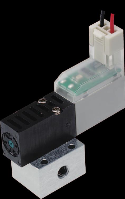
3 QE/Z Series Easy use Upward/lateral common wiring connecr used The specification can be changed simply by changing the insertion direction. No polarity. Choose any option without fear of operation faults. A manual override can be selected in accordance with equipment maintenance. Non-locking Environmental Low power realized Reliable Durability: DC: 00 million times, AC: 0 million times C or below * In accordance with in-house test conditions. Prevents malfunction Standard (DC) 0 Coil temperature rise value [ C] Energy saving waveform Applied voltage 4 V 0V 0.4 W [Uses PWM control circuit] It prevents malfunction due impact and vibration. [Improved start up responsivity after shutdown] The adoption of low-adhesion rubber enables stable start up response time even after being out of use for long periods. [Port P filter as standard] It prevents snagging due foreign matter, enabling stable operation. Reduced power consumption 0.1 W 0W Locking (patent pending) Long service life realized Low power, low exoergic realized. Suppresses temperature rise Low exoergic/ energy circuit High maintainability 70 ms Enables continuous energization (option) Uses a new coil actuar. The low exoergic/energy type is capable of continuous energization. Applications For controlling air operated valves For controlling compact actuars such as single acting cylinders and air grinders


 HP 0.")

 (QRB+QB) Specifications Select the ideal model according the")
 For low vacuum/positive pressure H 0.0-0.1 0.")

4 QB Series High performance Compact and lightweight Valve width mm Weight 1. g Large flow rate High response Low-adhesion rubber is used. Stable response can be achieved. ms or less According JIS B 8419:0 Dynamic performance testing. Low vacuum/positive pressure switching The spring load and coil vacuum force have been optimized maximize the flow rate. HV 0.18 dm /(s bar) HP 0.11 dm /(s bar) Long service life Durability: 0 million operations * In accordance with in-house test conditions. Low vacuum and positive pressure can be freely combined. The product can be used as a single unit as well as be cusmized according your needs. (Cusm order product) (QRB+QB) Specifications Select the ideal model according the application. Applications Pressure specification Max. working pressure MPa Min. working pressure MPa C dm /(s bar) For low vacuum/positive pressure H For positive pressure HP For low vacuum HV Applications Low vacuum/positive pressure switching applications Mounting electronic parts -position QB1 option H Low vacuum Nozzle Positive pressure Electronic parts Pressure SW -position QB1 option HP QB1 option HV Atmospheric release Positive pressure Low vacuum Nozzle Electronic parts Pressure SW
 Pressurization is possible from any port.")

 Large flow rate Large flow rate Standard 0.4 dm/(s bar) 0.")


5 QRA/B Series Original universal structure Universal structure High response 4±1ms/ 1.±1ms(ON/OFF) Pressurization is possible from any port. Original balance poppet structure that achieves a large flow rate. According JIS B 8419:0 Dynamic performance testing. Long service life Durability: 0 million operations * In accordance with in-house test conditions. Self-hold (option) Large flow rate Large flow rate Standard 0.4 dm/(s bar) 0. dm/(s bar) Capable of status retention in Port 1 ON case of power failure (at vacuum). Does not require continuous energization, which reduces electric 0 V power consumption and heat generation. Electric power consumption and heat generation reduced! Port ON High-speed tact Ensures high-speed tact of vacuum burst without positive pressure. Increased vacuum flow rate means suction time can also be reduced. ON Electric signal OFF Large flow rate enabling high-speed atmosphere release Conventional products Atmospheric pressure Vacuum pressure QR Large flow rate enabling high-speed vacuum achievement t time Applications Suction/transport of electronic parts ON/OFF control of air blow Mounting or conveying head Parts feeder Conveyance unit Box for defective products Mounting base Passed product Discrete chip tray QR LSI tray Wafer Blow unwanted chips with air blower

![of Ports Position Number of solenoids JIS symbol Flow characteristics C [dm /(s bar)] *1 Applicable cylinder bore size](/docs-images/77/75234982/images/6-1.jpg "Voltage [V] -position single (self-reset) -position single (self-hold) Mix manifold M Grommet lead wire C connecr D connecr")


 QB1-H(P) QB1-HV (A) 1(P) (A) 1(V) (R) (R) 0.11 0.")

6 Series variation Valve performance Switching position Port Electrical connections size Electrical connections/series external appearance No. of Ports Position Number of solenoids JIS symbol Flow characteristics C [dm /(s bar)] *1 Applicable cylinder bore size Voltage [V] -position single (self-reset) -position single (self-hold) Mix manifold M Grommet lead wire C connecr D connecr E connecr EJ connecr Page Single unit QE1 -port -position single (NC) Without manual override φ6 φ0 0 AC 4 DC 1 DC DC DC 1 QE Series Individual wiring manifold side piping Individual wiring manifold rear piping MQE1 MQZ1 -port -port 1 With manual override φ6 φ0 φ6 φ0 0 AC 4 DC 1 DC DC DC 0 AC 4 DC 1 DC DC DC 1 1 QB Series Single unit Individual wiring manifold QB1 MQB1 -port -port -position single (NC) QB1-H(P) QB1-HV (A) 1(P) (A) 1(V) (R) (R) φ6 φ0 φ6 φ0 4 DC 1 DC 4 DC 1 DC 7 7 QRA1 -port -position universal (self-reset) φ6 φ 4 DC 1 DC 1 QRA/QRB Series* Single unit Individual wiring manifold QRB1 MQRA1 MQRB1 -port -port -port 1 Port numbers 1,, and are Port 1: P, NC Port : A, COM Port : R and NO. (self-hold) 1 Port numbers 1,, and are Port 1: P, NC Port : A, COM Port : R and NO φ6 φ φ6 φ φ6 φ 4 DC 1 DC 4 DC 1 DC 4 DC 1 DC *1: Effective cross-sectional area S and sonic conductance C are converted as S.0 x C. *: For QRA and QRB Series, large flow rate (H) cannot be selected for flow rate size. Intro 1
7 Electrical connection circuit diagram QE Series Q Series Electrical connection circuit diagram Electrical connections Without lead wire With lead wire With indicar lamp With surge suppressor Without socket Circuit diagram (±) Blank Grommet lead wire DC ( ) E0 E connecr E0*J EJ connecr E0N E connecr E1 E connecr E E connecr (±) DC ( ) ( ~ ) AC 0 V ( ~ ) (±) DC E*J EJ connecr ( ) EN E connecr E E connecr ( ~ ) AC 0 V ( ~ ) E E connecr (±) Option S E*J EJ connecr EN E connecr DC ( ) Option E E E connecr E*J EJ connecr EN E connecr (±) DC ( ) Control circuit QB Series Wiring circuit (+) (-) Control circuit Connection C connecr (C*/C) D connecr (D*/D) Polarized QRA/QRB Series Voltage Solenoid position Option Wiring circuit Connection DC -position single (self-reset) -position single (self-hold) - With surge suppressor and indicar lamp Large flow rate with surge suppressor/ lamp With surge suppressor and indicar lamp (±) (±) (±) (±) (Red) (+) (Black) (-) (-) (+) (-) Control circuit Control circuit Grommet lead wire (blank) No polarity C connecr (C*/C) D connecr (D*/D) No polarity C connecr (C*/C) D connecr (D*/D) Polarized C connecr (C*/C) D connecr (D*/D) Polarized Intro

8 Direct acting -port valve Single valve/sub-plate piping QE Series Individual wiring manifold/sub-plate piping MQE Series Cylinder bore size: φ6 φ0 JIS symbol -position single (NC) Without manual override With manual override 1 1 Common specifications Descriptions Valve and operation Working fluid Content Direct acting poppet valve Compressed air Max. working pressure MPa 0.7 Min. working pressure MPa 0 Proof pressure MPa 1.0 Ambient temperature C - (no freezing) Fluid temperature C Manual override None/Non-locking manual/ Locking manual Lubrication *1 Not required Degree of protection * Dust-proof Vibration resistance m/s 0 or less Shock resistance m/s 00 or less Atmosphere Port size Cannot be used in corrosive gas environments M *1. Use turbine oil Class 1 ISO VG for lubrication. *. The weight listed is the weight without the base. Electrical specifications Descriptions Rated voltage V Content Standard Low exoergic/energy,, 1, 4 VDC 0 VAC Voltage fluctuation range ±% Holding current A * 1 VDC, 4 VDC VDC 0.(0.16) - VDC 0.07(0.08) - 1 VDC 0.00(0.04) (0.0) 4 VDC 0.01(0.017) (0.00) 0 VAC 0.009(0.0) - VDC 0.(0.40) - Power VDC 0.(0.40) - consumption W * 1 VDC 0.(0.40) 0. 4 VDC 0.(0.40) 0. Apparent power VA Values in ( ) are with lamp 0 VAC 0.9(0.98) - Thermal class B Surge suppressor Indicar Option LED *. Values in ( ) apply when lamp is included. In addition, the type with low exoergic/energy circuit is only available with lamp. Performance/Characteristics Descriptions Flow characteristics QE 1 : 0.04 dm /(s bar), : 0.06 dm /(s bar) Response time *4 ON:6ms OFF:ms Weight * 16g *4. According JIS B 8419:0 Dynamic performance testing. (The response times are values with working pressure of 0. MPa at 0 C, without lubrication.) *. The weight listed is the weight without the base. Ozone-proof specifications Conforms low-concentration ozone specifications as standard. CE marking specifications ** Voltage ST 1
9 How order Single valve QE1 Single valve for mounting base QE1 Manifold model No. Side piping manifold MQE1 Rear piping manifold A Model No MQZ Operation B Solenoid position Manual override M 00 M 0 M Electrical connections C Port size M M1 M1 E E0 D Manual override Precautions for model No. selection *1: The grommet lead wire specifications are compatible with DC voltage only. *: E* type and E*J connecrs support 1/4 VDC only. In addition, surgeless "S" and low exoergic/energy circuit "E" cannot be selected gether. *: Surgeless specifications. *4: A filter is built in port P as standard. [Example of model No.] MQE1-M-M1E0A-- A Model No. : Side piping manifold B Solenoid position : -position normally closed C Port size : M D Manual override : Locking manual override E Electrical connections : E connecr, lead wire 00 mm F Option : Fluorine specification G Station No. : stations H Voltage : 4 VDC How order masking plate kit QE1 MP KIT A E E Electrical connections Blank Without manual override M Non-locking manual override M1 Locking manual override H Voltage Blank Grommet lead wire E* E connecr EJ* EJ connecr E1 E connecr with socket/terminal Lead wire length 00 mm * Gasket/mounting screw attached Lead wire length 00 mm 00 mm 00 mm 000 mm 000 mm F Option G Station No. Lead wire length 00 mm 000 mm 000 mm QE Series How order Solenoid position 1 -position single normally closed 8 Mix manifold C Port size M M D Manual override Blank Without manual override M Non-locking manual override M1 Locking manual override E Electrical connections Blank Grommet lead wire (00 mm) *1 E0 E connecr, lead wire (00 mm) E00 E connecr, lead wire (00 mm) E01 E connecr, lead wire (1,000mm) E0 E connecr, lead wire (,000mm) E0 E connecr, lead wire (,000mm) E0N E connecr without lead wire (without socket) E1 E connecr without lead wire (with socket/terminal) E E connecr, lead wire (00 mm) with lamp/surge suppressor E0 E connecr, lead wire (00 mm) with lamp/surge suppressor E1 E connecr, lead wire (1,000 mm) with lamp/surge suppressor E E connecr, lead wire (,000 mm) with lamp/surge suppressor E E connecr, lead wire (,000 mm) with lamp/surge suppressor EN E connecr without lead wire (without socket) with lamp/surge suppressor E E connecr without lead wire (with socket/terminal) with lamp/surge suppressor E01J EJ connecr, lead wire (1,000 mm) E0J EJ connecr, lead wire (,000 mm) E0J EJ connecr, lead wire (,000 mm) E1J EJ connecr, lead wire (1,000 mm) with lamp/surge suppressor EJ EJ connecr, lead wire (,000 mm) with lamp/surge suppressor EJ EJ connecr, lead wire (,000 mm) with lamp/surge suppressor F Option A Ozone/coolant proof S Surgeless * E Low exoergic/energy circuit *, * F Port A filter integrated *4 G Station No. stations 0 0 stations H Voltage 1 0 VAC (rectifier integrated) 4 VDC 4 1 VDC 7 VDC 8 VDC E0N E connecr without socket A Model No.MQZ1B MQE1QE1
10 QE Series Dimensions (QE) QE1-M -position single: grommet lead wire. 9.4 E connecr (E).7 connecr lateral 0.9 connecr upward 1 1. Lead wire length: 00 (AWG#6, O.D. φ1.) 0.9 -φ.7 Mounting hole (41.4) connecr lateral 4.8 (46.) connecr upward M 0.8 M 0.8 M port 0 -port 1-port EJ connecr (E*J) Non-locking manual override (M) Locking manual override (M1) Non-locking Locking manual override manual override (41.) connecr lateral 68. (71.7) connecr upward QE position single: grommet lead wire 0.8 connecr upward 61. connecr lateral Non-locking manual override (M) Non-locking manual override Locking manual override (M1) 0. (full circumference) R Gasket dimensions Locking manual override
11 Dimensions (MQE/MQZ) MQE1-M -position single: grommet lead wire E connecr (E) QE Series Dimensions 11.. pitch L L M port 44.4 (47.8) connecr upward 9.6 (4.0) connecr lateral φ. Mounting hole Lead wire length 00 (AWG#6, O.D. φ1.) MQZ1-M -position single: grommet lead wire -φ. Mounting hole 11.. pitch. pitch L L1 1 1 n-m 0.8 -port M 0.8 -port EJ connecr (E*J) -M port M 0.8 -port 69.9 (7.) connecr upward E connecr (E) 9. (4.9) connecr lateral 44.4 (47.8) connecr upward 9.6 (4.0) connecr lateral connecr upward 0.8 connecr upward 0.9 connecr upward..6 connecr lateral. 61. connecr lateral.6 connecr lateral 11.. pitch n-m 0.8 -port Station No L L
12 QE Series Dimensions (MQE) MQE1-M Non-locking manual override (M) (manual operation position) 0. -φ. Mounting hole E connecr (E) EJ connecr (E*J) MQE1-M Locking manual override (M1) E connecr (E) (manual operation position) φ. Mounting hole 11.. pitch 1 1 Lead wire length 00 (AWG#6, O.D. φ1.) Lead wire length 00 (AWG#6, O.D. φ1.) pitch. pitch L L1 L L1 1 1 n-m 0.8 -port M port M 0.8 -port.1 -M port M 0.8 -port 44.4 (47.8) connecr upward 9.6 (4.0) connecr lateral (7.) connecr upward 9. (4.9) connecr lateral 44.4 (47.8) connecr upward 9.6 (4.0) connecr lateral connecr upward EJ connecr (E*J) 69.9 (7.) connecr upward 0.8 connecr upward 9. (4.9) connecr lateral. 0.7 connecr upward.6 connecr lateral..6 connecr lateral 61.1 connecr lateral pitch n-m 0.8 -port 0.7 connecr upward 61.1 connecr lateral Station No L L
13 Internal structure and parts list QE Series Internal structure and parts list How use the E and EJ types 1 1 No. Part name Material Body Resin Body (plug) Resin Valve seat Nitrile rubber 4 Valve spring Stainless steel O-ring Hydrogenated nitrile rubber 6 Body gasket Hydrogenated nitrile rubber 7 Valve guide Resin 8 Plunger Stainless steel 9 Coil gasket Silicone rubber Buffer sheet Resin 11 Coil assembly - 1 Plunger spring Stainless steel How use the E and EJ models How use the E connecr The E connecr has p and side connecrs which sockets can be connected. The socket assembly is connected from the upward direction at shipment. Select the connection direction based on the installation environment. How mount and remove socket When mounting the socket, hold the lever and socket with fingers and insert straight in the square window on the connecr body. Align the lever jaw with the groove on the connecr body and lock it. When mounting from the p, position the socket so that the lever faces the front. When mounting from the side, position the socket so that the lever is in an upward direction. When pulling out the socket, press down the lever release its jaw from the groove, then pull straight out. Lever Socket Groove How connect lead wire Strip the end of the lead wire by about mm. Align the end of the core wires, insert them in the contact terminal, and crimp with a crimping ol. When crimping, check that both the sheath and core wires are held, and 0 0. mm of the core wire end is visible. After crimping, position the contact terminal as shown below, and insert in the square window on the socket. The terminal locks when it is inserted the end. After inserting, pull the terminal lightly check that it is locked. Sheath and core wires are held Core wires can be seen Wire size mm AWG mm How use the E J connecr Use the lead wire with limited bending as shown in the figure below. R R 6
14 Direct acting -port valve Single valve/sub-plate piping QB Series Individual wiring manifold/sub-plate piping MQB Series Cylinder bore size: φ6 φ0 JIS symbol -position single (NC) QB1-H(P) (A) 1(P) QB1-HV (A) (R) 1(V) (R) Common specifications Descriptions Content Valve and operation Working fluid Direct acting poppet valve Compressed air, low vacuum Max. working pressure MPa Refer Individual specifications listed below Min. working pressure MPa Refer Individual specifications listed below Proof pressure MPa 1.0 Ambient temperature C 0 0 Fluid temperature C 0 Lubrication Degree of protection Vibration resistance m /s Not available Dust-proof 0 or less Shock resistance m /s 00 or less Atmosphere Cannot be used in corrosive gas environments Electrical specifications Descriptions Standard specifications Rated voltage V DC 1, 4 Voltage fluctuation range ±% Starting current Holding current A A 4 VDC VDC VDC VDC 0.00 Power consumption W 0.6 *1 Thermal class *1:.W for 0 ms after start. B Individual specifications Descriptions QB1-H QB1-HP QB1-HV Max. working pressure MPa 0. * Min. working pressure MPa -0.1 * *: When used with positive pressure only, the operating pressure range will be MPa. Performance/Characteristics Descriptions QB1-H QB1-HP QB1-HV Response time * ms or less Flow characteristics C [dm /(s bar)] 1 :0.11, :0.11 1:0.18, :0.11 Weight g 1. *: According JIS B 8419:0 Dynamic performance testing. (The response times are values with working pressure of 0. MPa at 0 C, without lubrication.) Ozone-proof specifications Conforms low-concentration ozone specifications as standard. ** CE marking specifications Specifications for rechargeable battery Conforms CKD P4 Series equivalent specifications as standard. UL standards specifications Voltage ST ** Voltage UL (cusm order) 7
15 How order Sub-plate piping QB1 1 0 M C H Single solenoid valve QB1 Manifold MQB M D C H H P V QB Series How order A Model No. Electrical connections QB C C connecr/with lead wire with surge suppressor/lamp Lead wire length C :00mm C0 :00mm C1 :00mm C :000mm Solenoid valve operation classification B Solenoid position C Port size Precautions for model No. selection *1: Combination with a masking plate. The pressure specification options Blank, P and V cannot be combined. *: Vacuum the negative pressure from port (R). This will be the NO specification. [Example of model No.] MQB1-M-CH-7- A Model: MQB1 B Solenoid position : -position single C Port size : M D Electrical connections : Lead wire (00 mm) E Pressure specification : Blank F Station No. : 7 stations G Voltage : 4 VDC How order masking plate kit QB1 QB1 MP MP KIT KIT V * D D connecr/with lead wire with surge suppressor/lamp Lead wire length D :00mm D0 :00mm D1 :00mm D :000mm F Station No. E Pressure specification D Electrical connections *: Pressure specification (V dedicated) Note: Gasket/mounting screw attached G Voltage A Model No. Code Content QB1 MQB1 B Solenoid position 1 -position single normally closed 8 Mix manifold *1 C Port size M M D Electrical connections C connecr (lead wire lateral direction) C Lead wire (00 mm) with surge suppressor/lamp C0 Lead wire (00 mm) with surge suppressor/lamp C1 Lead wire (00 mm) with surge suppressor/lamp C Lead wire (000 mm) with surge suppressor/lamp CN Without lead wire (without socket) C Without lead wire (with socket/terminal) D connecr (lead wire upward direction) D Lead wire (00 mm) with surge suppressor/lamp D0 Lead wire (00 mm) with surge suppressor/lamp D1 Lead wire (00 mm) with surge suppressor/lamp D Lead wire (000 mm) with surge suppressor/lamp DN Without lead wire (without socket) D Without lead wire (with socket/terminal) E Pressure specification Blank Positive/negative pressure specification ( MPa) * P Positive pressure specification ( MPa) V Negative pressure specification ( MPa) F Station No. stations 0 0 stations G Voltage 4 VDC 4 1 VDC 8
16 QB Series Dimensions (QB1) QB1-M Options Blank, P -position single: C connecr (C/C) D connecr (D/D) M 0.8 (R) port.7 6. Lead wire (AWG#6, O.D. φ1.) (D,D*) 0.9 Lead wire (AWG#6, O.D. φ1.) (C,C*) -φ.6 Mounting hole QB1-M Option V -position single: C connecr (C/C) D connecr (D/D) M 0.8 (R) port φ.6 Mounting hole M 0.8 (A) Port M (P) port 0.9 Lead wire (AWG#6, O.D. φ1.) (C,C*) 4.1 Lead wire (AWG#6, O.D. φ1.) (D,D*). M 0.8 (A) port M 0.8 1(V) port 9
17 Dimensions (QB119) QB Series Dimensions QB Options Blank, P -position single: C connecr (C/C) D connecr (D/D) 7.9 Lead wire (AWG#6, O.D. φ1.) (D,D*) Lead wire (AWG#6, O.D. φ1.) (C,C*).6 6 Single solenoid valve back surface Gasket (6.8) 1(P) (A) (R) Port opening dimensions QB Option V -position single: C connecr (C/C) D connecr (D/D) 7.9 Lead wire (AWG#6, O.D. φ1.) (D,D*) Lead wire (AWG#6, O.D. φ1.) (C,C*).6 6 Single solenoid valve back surface Gasket.6.6 1(V) (A) (R) Full circumference Port opening dimensions
18 QB Series Dimensions (MQB1) MQB1-M Options Blank, P -position single: C connecr (C/C) D connecr (D/D) 11.. n-m 0.8 (A) port Lead wire (AWG#6, O.D. φ1.) (D,D*) 1 Station No L L MQB1-M Option V -position single: C connecr (C/C) 1 D connecr (D/D)... Pitch 46 Lead wire (AWG#6, O.D. φ1.) (C,C*) -φ. Mounting hole 41 M 0.8 (R) port.. L1 L M (P) port. Lead wire (AWG#6, O.D. φ1.) (D,D*) 1. Pitch 46 Lead wire (AWG#6, O.D. φ1.) (C,C*) -φ. Mounting hole 41 M 0.8 (R) port n-m 0.8 (A) port L1 L M (P) port Station No L L
19 Internal structure and parts list QB Series Dimensions No. Part name Material 1 Body Resin Valve seat Nitrile rubber Valve spring Stainless steel 4 Plug Resin Body gasket Fluoro rubber 6 O-ring Fluoro rubber 7 Plunger spring Stainless steel 8 Plunger Stainless steel 9 Coil assembly - C/D connecr wiring method Referring the figure below, wire the connecrs with (1) (4). [Procedure] (1) Peel the sheath at the end of the lead wire by mm. () Crimp the lead wire with a dedicated ol. () Insert the terminal in holes at both ends of the socket. (Note) Check the orientation for insertion. (4) Insert the socket in the solenoid valve connecr section. Socket Socket model No. MO-SOCKET-SET ( crimp terminals attached, applicable wire diameter: AWG6 8) (4) Insert socket Crimp terminal (manuf. by own company) Crimping ol (manufactured by CKD) * For the details of crimp terminals and crimping ols, contact CKD. () Insert the terminal () Terminal crimping section (1) Lead wire AWG6 8 ( mm ) (+) Red (-) Black Note: Be careful with the polarity of with the lamp and surge suppressor equipped models. An incorrect polarity will not result in a shortcircuit, but the valve will not operate. 1
 1 Port numbers 1, and are Port 1: P, NC Port : A, COM Port : R, NO. (self-hold) 1 Port numbers 1, and are Port 1: P, NC Port : A, COM Port : R, NO.")
 Max. working pressure differential MPa 0.")
20 Direct acting -port valve Single valve Body piping/sub-plate piping QRA/QRB Series Individual wiring manifold Body piping/sub-plate piping MQRA/MQRB Series Cylinder bore size: φ6 φ JIS symbol -position universal (self-reset) 1 Port numbers 1, and are Port 1: P, NC Port : A, COM Port : R, NO. (self-hold) 1 Port numbers 1, and are Port 1: P, NC Port : A, COM Port : R, NO. Common specifications Descriptions Content Valve and operation Direct acting poppet valve Working fluid Compressed air, low vacuum Max. working pressure MPa 0.70 Min. working pressure MPa Low vacuum: -0 kpa Proof pressure MPa 1.0 (low vacuum: -1 kpa) Max. working pressure differential MPa 0.70 Ambient temperature C - 0 (no freezing) Fluid temperature C 0 Lubrication Not available *1 Degree of protection Dust-proof Vibration resistance m /s 0 or less Shock resistance m /s 00 or less Atmosphere Cannot be used in corrosive gas environment. *1 Lubrication will deteriorate the performance. Electrical specifications Descriptions Standard specs Large flow specs H Rated voltage V DC 4/1 Energizing rate Intermittent * Continuous * Voltage fluctuation range ±% 4 VDC Starting current A 1 VDC VDC Holding current A 1 VDC Power consumption W.0.4 *4 Thermal class B *: Limit energizing within minutes and energization ratio 0% or less. Min. time of excitation for self-holding is 0 ms. *: Refer the precautions for continuous energization on page 4. *4:. W for 0 ms after start. Individual specifications Descriptions Port size Port 1 Port Port Performance/Characteristics QRA11 QRB11 QRA1 QRB1 MQRA11 MQRB11 MQRA1 MQRB1 Rc1/8 M M Rc1/8 Descriptions QRA11 QRB11 QRA1 QRB1 MQRA11 MQRB11 MQRA1 MQRB1 Response time * ON/OFF ms 4±1 / 1.±1 or less 4±1 / 1.±1 or less Weight g (single solenoid valve) (single solenoid valve) *: According JIS B 8419:0 Dynamic performance testing. (The response times are values with working pressure of 0. MPa at 0 C, without lubrication.) Flow characteristics Port 1 Port 1 Port Port Model No. Option C[dm /(s bar)] S (reference value) [mm ] C[dm /(s bar)] S (reference value) [mm ] C[dm /(s bar)] S (reference value) [mm ] C[dm /(s bar)] S (reference value) [mm ] QRA1 Blank H QRB1 Blank H MQRA1 Blank H MQRB1 Blank H Ozone-proof specifications Conforms low-concentration ozone specifications as standard. Specifications for rechargeable battery Conforms CKD P4 Series equivalent specifications as standard. CE marking specifications ** Voltage ST 1
21 How order Single solenoid valve QRB1 1 0 M D Single solenoid valve QRA1 1 9 M D QRA/QRB Series How order QRB1 Manifold MQRA1 A Model No Solenoid valve operation classification 00 M B Solenoid position C Port size Precautions for model No. selection *1: For connection with the grommet lead wire (00 mm), "", -position single solenoid (self-hold) for B solenoid position, and "H", large flow rate for E flow rate are not selectable. *: For "", -position single solenoid (self-hold) for B solenoid position, "H" for E flow rate and "4" for G voltage are not selectable. *: Combination with a masking plate. Combination of A and B types is not available. Solenoid positions "1" and "" cannot be mixed. [Example of model No.] MQRA1-M-C-7- A Model: MQRA1 (body piping) B Solenoid position : -position single C Port size : M D Electrical connections : Lead wire 00 mm with surge suppressor and indicar lamp E Flow rate : Standard W F Station No. : 7 stations G Voltage : 4 VDC How order masking plate kit QR1 MP KIT Note: Gasket/mounting screw attached Electrical connections QRA11/QRB11 Blank Grommet lead wire C Lead wire 00mm Lead wire length C :00mm C0 :00mm C1 :00mm C :000mm D C E Flow rate 8 F Station No. D Electrical connections C connecr/with lead wire, with surge suppressor/lamp Lead wire C A Model No. Single unit Manifold G Voltage Body piping Sub-plate piping Body piping Sub-plate piping Code Content QRA1 QRB1 MQRA1 MQRB1 B Solenoid position 1 -position single (self-reset) -position single (self-hold) * 8 Mix manifold * C Port size M M D Electrical connections Grommet lead wire Blank Grommet lead wire (00 mm) *1 C type connecr (lead wire lateral direction) C Lead wire (00 mm) with surge suppressor/lamp C0 Lead wire (00 mm) with surge suppressor/lamp C1 Lead wire (00 mm) with surge suppressor/lamp C Lead wire (000 mm) with surge suppressor/lamp C Without lead wire, with surge suppressor/lamp D type connecr (lead wire upward direction) D Lead wire (00 mm) with surge suppressor/lamp D0 Lead wire (00 mm) with surge suppressor/lamp D1 Lead wire (00 mm) with surge suppressor/lamp D Lead wire (000 mm) with surge suppressor/lamp D Without lead wire, with surge suppressor/lamp E Flow rate Blank Standard W H Large flow rate.w.4w F Station No. stations 0 0 stations G Voltage 4 VDC 4 1 VDC C connecr/without lead wire, with surge suppressor/lamp D D connecr/with lead wire, with surge suppressor/lamp Lead wire length D :00mm D0 :00mm D1 :00mm D :000mm Lead wire D D connecr/without lead wire, with surge suppressor/lamp QRA1/QRB1 C C connecr/with lead wire, with surge suppressor/lamp Lead wire length C :00mm C0:00mm C1:00mm C:000mm C C connecr/without lead wire, with surge suppressor/lamp D D connecr/with lead wire, with surge suppressor/lamp Lead wire length D :00mm D0 :00mm D1 :00mm D :000mm D D connecr/without lead wire, with surge suppressor/lamp 14
22 QRA/QRB Series Single valve Dimensions (QRA11/QRB11) QRA1-M -position single: grommet lead wire M1.7 mounting screws Torque N m C connecr (C/C) Lead wire (AWG#6, O.D. φ1.) (C,C*) 9. Lead wire length: 00 (AWG#6, O.D. φ1.) φ.4 (Mounting hole) 11 M 0.8 -port Non-locking Manual override D connecr (D/D) Lead wire (AWG#6, O.D. φ1.) (D,D*) M 0.8 M 0.8 -port 1-port QRB1-M -position single: grommet lead wire C connecr (C/C) 46.1 M 0.8 (-port) 6 Lead wire (AWG#6, O.D. φ1.) (C,C*) M1.7 mounting screws Torque N m -φ. (mounting hole) D connecr (D/D).8. 1 Lead wire length: 00 (AWG#6, O.D. φ1.) 1. M 0.8 (1-port) Non-locking manual override Lead wire (AWG#6, O.D. φ1.) (D,D*) M 0.8 (-port) QRA/B (single solenoid valve) -position single: grommet lead wire QRB QRA1 -M1.7 Mounting screws Torque N m M 0.8 -port 1 Non-locking manual override 4.. Lead wire length: 00 (AWG#6, O.D. φ1.) Mounting screw pitch C connecr (C/C) D connecr (D/D) Lead wire (AWG#6, O.D. φ1.) (C,C*) Lead wire (AWG#6, O.D. φ1.) (D,D*)
23 Dimensions (MQRA11/MQRB11) MQRA1-M -position single: grommet lead wire MQRA/MQRB Series Single valve C connecr (C/C) 4 L L1 = L - 8 Lead wire (AWG#6, O.D. φ1.) (C,C*). 14. (Pitch) Non-locking manual override n-m1.7 mounting screws Torque N m n-m 0.8 -port Mounting hole -φ4.4 Lead wire length: 00 (AWG#6, O.D. φ1.).9 4-Rc1/8 1, -port D connecr (D/D) Lead wire (AWG#6, O.D. φ1.) (D,D*) MQRB1-M -position single: grommet lead wire C connecr (C/C) 4 L L1 = L (Pitch) Lead wire (AWG#6, O.D. φ1.) (C,C*) Non-locking manual override n-m1.7 mounting screws Torque N m Mounting hole -φ4.4 Lead wire length: 00 (AWG#6, O.D. φ1.). 4-Rc1/8 1, -port D connecr (D/D) Lead wire (AWG#6, O.D. φ1.) (D,D*) (Pitch) n-m 0.8 -port Station No L L
24 QRA/QRB Series Individual wiring manifold Dimensions (QRA1/QRB1) QRA-M -position single: C connecr (C/C) Lead wire AWG #6 Length 00,000 mm (C/C*) 7.8 -φ.4 (Mounting hole) Non-locking manual override M1.7 mounting screws Torque N m 11 M 0.8 -port D connecr (D/D) Lead wire (AWG#6, O.D. φ1.) (D,D*) Non-locking manual override M 0.8 -port QRB-M -position single: C connecr (C/C) M 0.8 -port M port 6 D connecr (D/D) Lead wire (AWG#6, O.D. φ1.) (D,D*) M1.7 mounting screws Torque N m -φ. (Mounting hole) Lead wire AWG #6 Length 00,000 mm (C/C*).8 1. Non-locking manual override M port Non-locking Manual override M 0.8 -port QRA/QRB19-00 (single solenoid valve) -position single: C connecr (C/C) Lead wire AWG #6 0. Length 00,000 mm (C/C*) D connecr (D/D) Lead wire (AWG#6, O.D. φ1.) (D,D*). Non-locking manual override M1.7 mounting screws Torque N m M 0.8 -port Non-locking manual override Mounting screw pitch
25 Dimensions (MQRA1/MQRB1) MQRA-M -position single: C connecr (C/C) MQRA/MQRB Series Technical data D connecr (D/D) L 4 L1 = L - 8 Lead wire AWG #6 Length 00,000 mm (C/C*) 14. (pitch). Lead wire (AWG#6, O.D. φ1.) (D,D*) Non-locking manual override MQRB-M -position single: C connecr (C/C) D connecr (D/D) Mounting hole -φ4.4 n-m 0.8 -port 4-Rc1/8 1, -port Non-locking manual override L Lead wire AWG #6 Length 00,000 mm (C/C*) 4 14 L1 = L - 8. (pitch) 9.6 Lead wire (AWG#6, O.D. φ1.) (D,D*) Non-locking manual override -M1.7 mounting screws Torque N m Non-locking manual override Mounting hole -φ4.4 4-Rc1/8 1, -port 14. (pitch) n-m 0.8 -port Station No L L
26 QRA/QRB Series Internal structure and parts list -position single (self-reset) 1 Main parts list No. Part name Material 1 Body Resin 1 Port numbers 1,, and are Port 1: P, NC Port : A, COM Port : R and NO. 4 Body (plug) Resin Manual butn Resin 4 Valve spring Stainless steel O-ring Fluoro rubber 6 Body gasket Fluoro rubber 7 Valving element Aluminum, hydrogenated nitrile rubber 8 Plunger spring Stainless steel Plunger Stainless steel Coil assembly - -position single (self-hold) 1 Port numbers 1,, and are Port 1: P, NC Port : A, COM Port : R and NO Main parts list No. Part name Material 1 Body Resin Body (plug) Resin Manual butn A Resin 4 Valve spring Stainless steel O-ring Fluoro rubber 6 Body gasket Fluoro rubber 7 Valving element Aluminum, hydrogenated nitrile rubber 8 Plunger spring Stainless steel 9 Plunger Stainless steel Coil assembly - 11 Manual butn B Resin 1 Manual block Resin Operational principle -position single (self-reset) The QR Series structure is a pressure balanced type poppet valve, which is not affected by the working pressure and achieves a low wattage, large flow rate performance. It can be pressurized from any of ports 1,, or. The stem assembly valve seat and packing have the same diameter, so each port pressure differential is canceled by the stem assembly's through hole and pressure is balanced at both ON and OFF. When not energized The stem assembly is pushed ward port 1 side by the plunger spring force transmitted by the plunger. Port 1 is closed due the stem assembly valve seat and packing. Ports and are opened. Plunger Plunger spring Stem assembly When energized When energizing the coil, the plunger is suctioned ward the coil side, while the stem assembly is moved by the stem spring force and Ports 1 and are opened. Port is closed. Coil 1 1 Valve seat Packing Stem spring Body 19
27 -position single (self-hold) [Input signal and solenoid valve status] QRA/QRB Series Connecr method Coil Control circuit White ( -port) Red (+COM) Black (1 port) [Energization and solenoid valve status] (1) Energized red and black (Green indicar lamp on) 1 () Energized red and white (Red indicar lamp on) 1 [Operational principle] Coil Fixed core Moving core A Magnet Spring force B Magnet Spring force [Energized red and black] The coil force is in the A direction, causing the magnet force + coil force A exceed the spring force: thus, the fixed core and moving core will adhere. (Even if power is shut OFF, it will remain adhered.) [Energized red and white] The coil force is in the B direction, causing the coil force B + spring force exceed the magnet force: thus, the fixed core and moving core will separate. (Even if power is shut OFF, it will remain separated.) C/D connecr wiring method -position single (self-reset) Referring the figure below, wire the connecrs with (1) (4). [Procedure] (1) Peel the sheath at the end of the lead wire by mm. () Crimp the lead wire with a dedicated ol. () Insert the terminal in holes at both ends of the socket. (Note) Check the orientation for insertion. (4) Insert the socket in the solenoid valve connecr section. Socket Socket model No. Q-SOCKET-SET ( crimp terminals attached, applicable wire diameter: AWG6 8) (4) Insert socket () Insert the terminal Crimp terminal (manuf. by own company) Crimping ol (manufactured by CKD) () Terminal crimping section * For details of crimp terminals and crimping ols, contact CKD. (1) Lead wire AWG6 8 ( mm ) (-) Black (+) Red Note: Pay attention the polarity of for the optional H (large flow rate) specification. An incorrect polarity will not result in a short-circuit, but the valve will not operate. -position single (self-hold) Referring the figure below, wire the connecrs with (1) (4). [Procedure] (1) Peel the sheath at the end of the lead wire by mm. () Crimp the lead wire with a dedicated ol. () Insert the terminal in holes at both ends of the socket. (Note) Check the orientation for insertion. (4) Insert the socket in the solenoid valve connecr section. Socket Socket model No., Q-SOCKET-SET ( crimp terminals attached, applicable wire diameter: AWG6 8) (4) Insert socket Crimp terminal (manuf. by own company) Crimping ol (manufactured by CKD) () Terminal crimping section * For details of crimp terminals and crimping ols, contact CKD. () Insert the terminal (1) Lead wire AWG6 8 ( mm) (-) (+) (-) Note: Use caution with polarity of. An incorrect polarity will not result in a short-circuit, but the valve will not operate. 0
28 Safety Precautions Be sure read this section before use. When designing and manufacturing equipment using CKD products, the manufacturer is obligated ensure that the safety of the mechanism, pneumatic control circuit and/or water control circuit and the system that runs the electrical controls are secured. It is important select, use, handle and maintain CKD products appropriately ensure their safe usage. Observe warnings and precautions ensure device safety. Check that device safety is ensured, and manufacture a safe device. WARNING 1 This product is designed and manufactured as a general industrial machine part. It must be handled by an operar having sufficient knowledge and experience. Use this product in accordance with specifications. This product must be used within its stated specifications. In addition, never modify or additionally machine this product. This product is intended for use in general industrial machinery equipment or parts. It is not intended for use outdoors (except for products with outdoor specifications) or for use under the following conditions or environments. (Note that this product can be used when CKD is consulted prior its usage and the cusmer consents CKD product specifications. The cusmer should provide safety measures avoid danger in the event of problems.) ❶ Use for applications requiring safety, including nuclear energy, railways, aircraft, marine vessels, vehicles, medical devices, devices or applications in contact with beverages or foodstuffs, amusement devices, emergency cuff circuits, press machines, brake circuits, or safety devices or applications. ❷ Use for applications where life or assets could be significantly affected, and special safety measures are required. Observe organization standards and regulations, etc., related the safety of the device design and control, etc. ISO4414, JIS B 870 (General rules for pneumatic systems) JFPS008 (Principles for pneumatic cylinder selection and use) Including the High Pressure Gas Safety Act, Industrial Safety and Health Act, other safety rules, organization standards and regulations, etc. 4 Do not handle, pipe, or remove devices before confirming safety. ❶ Inspect and service the machine and devices after confirming safety of all systems related this product. ❷ Note that there may be hot or charged sections even after operation is spped. ❸ When inspecting or servicing the device, turn OFF the energy source (air supply or water supply), and turn OFF power the facility. Discharge any compressed air from the system, and pay attention possible water leakage and leakage of electricity. ❹ When starting or restarting a machine or device that incorporates pneumatic components, make sure that the system safety, such as pop-out prevention measures, is secured. Observe the warnings and cautions on the following pages prevent accidents. Precautions are ranked as "DANGER", "WARNING", and "CAUTION" in this section. DANGER: In the case where the product operation is mishandled and/or when the urgency of a dangerous situation is high, it may lead fatalities or serious injuries. WARNING: A dangerous situation may occur if handling is mistaken, leading fatal or serious injuries. CAUTION: A dangerous situation may occur if handling is mistaken, leading minor injuries or property damage. Note that some items indicated with "CAUTION" may lead serious results depending on the conditions. All items contain important information and must be observed. Limited warranty and disclaimer 1 Warranty period This warranty is valid for one (1) year after delivery the cusmer's designated site. Scope of warranty In case any defect clearly attributable CKD is found during the warranty period, CKD shall, at its own discretion, repair the defect or replace the relevant product in whole or in part and at no cost, according its own judgment. Note that the following failures are excluded from the warranty scope: (1) Failures due use outside the conditions and environments set forth in the catalog or these specifications. () Failures resulting from facrs other than this product. () Failures caused by improper use of the product. (4) Failures resulting from modifications or repairs made without CKD consent. () Failures caused by matters that could not be predicted with the technologies in practice when the product was delivered. (6) Failures resulting from natural disasters or accidents for which CKD is not liable. The warranty covers the actual delivered product, as a single unit, and does not cover any damages resulting from losses induced by malfunctions in the delivered product. Compatibility check The cusmer is responsible for confirming the compatibility of CKD products with the cusmer's systems, machines and equipment. 1
29 Pneumatic components Safety Precautions Be sure read this section before use. Product-specific cautions: Direct acting -port valve QE / QB / QRA/B Series Design/selection 1. Common WARNING Do not use this as a solenoid valve for emergency cuff. If left pressurized for long periods, the starting response could be delayed. The solenoid valve air leakage is greater than zero, and so long-term pressure retention is not possible. For applications requiring pressure retention, design sufficient margins for container volume and holding time. A mesh filter is built in the (A) port as standard prevent foreign substance from being suctioned in the pipe, but it cannot remove fine dust particles. When using this in vacuum conditions, install a vacuum filter between the pad nozzle and the valve. (QR Series) Note the items below when installing solenoid valves on non-ckd bases. Solenoid valve installation pitch shall be. mm and over. Base material is aluminum. As applications other than the above require consideration for heat dissipation, consult with CKD.. Surge suppressor CAUTION The surge suppressor attached with the solenoid valve is intended protect the output contacts for the solenoid valve drive. There is no significant protection for the other peripheral devices, and devices could be damaged or could malfunction due a surge. As well, surges generated by other devices may be absorbed and cause damage such as burning. Note the following points. The surge suppressor functions limit solenoid valve surge voltage, which can reach several hundred volts, a low voltage level that the output contact can withstand. Depending on the output circuit used, this may be insufficient and could result in damage or malfunction. Check whether the surge suppressor can be used within the surge voltage limit of the solenoid valve in use, the output device's withstand pressure and circuit structure, and by the degree of return delay time. When necessary, provide other surge countermeasures. Q Series solenoid valve with surge suppressor can also suppress inverse voltage surge that occurs when the product is turned OFF the level shown in the table below. Model Specification voltage Inverse voltage when OFF QE, QR VDC Approx. 6.V VDC Approx. 1V 1 VDC Approx. 7 V 4 VDC Approx. 47V When options "S", "E" or "H" are selected Approx. 1V QB 1 VDC, 4 VDC Approx. 1V If the output unit is an NPN type, a surge voltage equaling the voltage shown in the table above plus the power supply voltage may be applied the output transisr. Make sure install a contact protection circuit or select option "S" avoid the risk. [Output transisr protection circuit: Installation example 1] Programmable controller side [Output transisr protection circuit: Installation example ] Programmable controller side Solenoid valve side Solenoid valve side () If another device or solenoid valve is connected in parallel the solenoid valves, the inverse voltage surge generated when the valve is turned OFF would apply those devices. Even in the case of a solenoid valve with 4 VDC surge suppressor, the surge voltage may reach negative tens of volts for some models. This inverse voltage may cause damage or malfunction other components connected in parallel. Avoid parallel connection of devices susceptible inverse polarity voltages, e.g. LED indicar lamps. When driving several solenoid valves in parallel, the surge from other solenoid valves may enter the surge suppressor of one solenoid valve, and it may burn depending on the current value. When driving several solenoid valves with surge suppressors in parallel, surge current could concentrate at the surge suppressor with the lowest limit voltage and cause similar burning. Due the variations in surge suppressor limit voltage that exist even among solenoid valves of the same model No., in the worst case the surge suppressor may burn out. Avoid driving several solenoid valves in parallel. (4) The surge suppressor incorporated in the solenoid valve will often be short-circuited if it is damaged by overvoltage or overcurrent from other solenoid valves. Where there is a failed surge suppressor, if a large current flows when the output is ON, in the worst case scenario, the output circuit or solenoid valve could be damaged or ignited. Do not continue energizing in a state of failure. Additionally, prevent large currents from continuing flow, connect an overcurrent protection circuit the power supply and drive circuit, or use a power supply with overcurrent protection.. Surgeless (QE Series only) The surgeless type reduces the solenoid valve surge voltage down approx. 1V by the built-in diode. In addition, there is no polarity. Voltage V Approx. 1V
30 Q Series 4. Low exoergic/energy circuit (QE Series only) 6. Large flow rate (QRA/B Series only) The low exoergic/energy type includes a PWM circuit in the solenoid valve, which is designed reduce the current value when the coil is held with suction. Power consumption is reduced 1/4 compared standard products. In addition, there is no polarity. [Specifications for low exoergic/energy type] Descriptions Current A Power consumption W When starting When holding 1 VDC VDC VDC VDC Voltage V CAUTION Never use in environments where vibration or impact applied exceeds the specifications. This may result in valve malfunction. The large flow rate includes a current control circuit, which is designed reduce the current value when the coil is held with suction. Only plus common polarity is used. (+) Control circuit (-) PWM circuit 0.4 W 0.1 W Power W 70 ms Reduced power consumption V I CAUTION Do not use this valve in an environment where vibration and impact exceed the specified range. This may result in valve malfunction. The energized state cannot be maintained if power is cut off instantaneously for 0 ms or less on the power source driving the solenoid valve. If any disturbance has caused up 0 ms instantaneous power cut-off of the solenoid valve after being continuously energized, cut the power OFF for 0 ms or more before switching the solenoid valve ON again. CAUTION 0 ms 7. Vacuum specifications Select QB or QR Series when using the unit with vacuum. QE Series cannot be used under vacuum conditions, including vacuum burst applications. Do not use this product by gradually raising the voltage. The valve will not operate.. AC voltage specifications (QE Series only) CAUTION The models with AC voltage specifications have a built-in full-wave rectifier circuit. Depending on the type of SSR used turn ON/ OFF the solenoid valve, recovery failure of the valve may result. Use caution when selecting SSRs. (Consulting the manufacturer of the relay or PLC is recommended.)
31 Use/maintenance Q Series Safety precautions 1. Common CAUTION The coil may become hot due ambient temperature or energizing time. Be sufficiently careful when uching the valve. Use appropriate rque tighten the pipes when connecting them. The purpose is prevent air leakage and damage bolts. First tighten the bolts by hand ensure that the threads are not damaged, then use a ol. Port thread Tightening rque N m M Rc1/8 Tighten the solenoid valve with an appropriate rque when installing it. Excessive tightening may damage the valve. Use a #0 screwdriver. Model No. Tightening rque N m QRA/B 0.1±0.0 QE/QB 0.1±0.0. Continuous energizing CAUTION When using in a continuously energized state for long periods, use the low exoergic/energy type. (QE Series) When using the AC voltage type in a continuously energized state, the temperature of the coil's outer surface will be high. It may cause burns. Do not uch it when it is energized. (QE Series) Long energizing times cause performance deterioration of the solenoid valve. Note the following points for the standard flow rate in particular. (QRA/B Series) The energizing time should be the same as or below the de-energizing time for intermittent energizing. One energizing cycle should be minutes or less. Set so that the peripheral temperature of the solenoid valve does not exceed max. working temperature. If a valve other than the low exoergic/energy type is used in a continuously energized state for long periods, the valve performance may deteriorate more quickly. Furthermore, use caution under the following working conditions likewise. When the energized time exceeds non-energized time in intermittent operation When one energizing session exceeds 0 minutes in intermittent operation Give sufficient consideration heat dissipation when installing the product.. Manual override CAUTION QE Series How operate non-locking manual override Push the manual butn vertically with a thin-tipped ol. Locking manual override Rotate the manual butn in the direction of the arrow using a flathead screwdriver. After completing manual operation, rotate the manual butn return it its original position. Precautions Do not operate with excessive force. The solenoid valve could be damaged. Forgetting reset the locking manual override may lead malfunction. Be sure release the manual override after completing operation. QRA/QRB Series [-position single (self-reset)] Pressing the manual override can switch the main valve the solenoid position when energized. Press the manual override from the front using a thin-tipped ol such as a precision screwdriver. Pushing diagonally at this point may result in incomplete position switching and cause internal leakage. For normal operation, detach the ol and press it again from the front. [-position single (self-hold)] The flow path can be switched by pressing (1) and () in the manual override. () ((1): 1, (): ) Press the manual override from the front using a thin-tipped ol such as a precision screwdriver. 4. Self-hold type (QRA/B Series only) CAUTION Manual butn Non-locking manual override Manual butn Locking manual override Precautions when energizing Limit continuous energizing within 0 seconds. Limit energization ratio 0% or less. Min. time of excitation should be 0 ms or longer. Do not energize black and white lead wires simultaneously. Solenoid valves will not operate if they are simultaneously energized. The state before energizing will be maintained (the indicar lamp on both sides will light). Be cautious as the valve will be activated from that state if both sides are not turned OFF simultaneously. Malfunction may occur if a magnet comes close the solenoid valve. Install at least cm away from magnets. The holding position may change during installation and transport due impact exceeding the specifications. Before use, verify the position manually or electrically. (1) 4
32 QE Series Manifold specifications sheet How fill out MQE/Z1 manifold specifications sheet Manifold model No. MQE/ Z M - E A Piping *1 Port size Manual override Electrical connections Option Station No. Voltage *1: Mixing of the points specified above is not possible. Specify by model No. Part name Model No. Layout position Quantity Valve QE119-6 Masking plate QE1-MP Preparing manifold specifications sheet Complete from the left end, with the piping port facing forward. Select and fill out the appropriate form from the manifold specifications sheet for each model. MQE/Z1 Manifold specifications sheet Contact Quantity set(s) Delivery date / Slip No. Order No. Manifold model No. MQ E/Z M *1 Port size Manual override Electrical connections Option Station No. Voltage Date issued / / Company name Contact Order No. *1: Mixing of the points specified above is not possible. Specify by model No. Part name Model No. Layout position Quantity Valve Masking plate QE119- QE1-MP
33 QB Series Manifold specifications sheet How fill out MQB1 manifold specifications sheet Manifold model No. MQB M - C H P *1 Port size Connection Option Station No. Voltage *1: Mixing of the points specified above is not possible. Specify by model No. Part name Model No. Layout position Quantity Valve QB119-6 Masking plate QB1-MP- Preparing manifold specifications sheet Complete from the left end, with the piping port facing forward. Select and fill out the appropriate form from the manifold specifications sheet for each model. MQB1 Manifold specifications sheet Contact Quantity set(s) Delivery date / Slip No. Order No. Date issued / / Company name Contact Order No. Manifold model No. MQB M - H - - *1 Port size Connection Option Station No. Voltage *1: Mixing of the points specified above is not possible. Specify by model No. Part name Model No. Layout position Quantity Valve Masking plate QB119- QB1-MP- 6
34 QRA/QRB Series Manifold specifications sheet How fill out MQRA/B1 manifold specifications sheet Manifold model No. MQRA/ B M - C H Piping *1 Port size Electrical connections Option Station No. Voltage *1: Mixing of the points specified above is not possible. Specify by model No. Part name Model No. Layout position Quantity QRA119- Valve QRB119-6 QRA19- QRB19- Masking plate QR1-MP Preparing manifold specifications sheet Complete from the left end, with the piping port facing forward. Select and fill out the appropriate form from the manifold specifications sheet for each model. MQRA/B1 Manifold specifications sheet Contact Quantity set(s) Delivery date / Slip No. Order No. Date issued / / Company name Contact Order No. Manifold model No. MQR A/B M *1 Port size Electrical connections Option Station No. Voltage *1: Mixing of the points specified above is not possible. Specify by model No. Part name Model No. Layout position Quantity QRA119- Valve QRB119- QRA19- QRB19- Masking plate QR1-MP 7


")


35 Related products QR negative pressure switching unit MVQRA1/MVQRB1 Series Ideal for suction transport of small articles Utilizing QR's large flow rate and high responsivity, it achieves highspeed stabilization of the suction/transport process without a positive pressure source Footprint minimized A thin and lightweight manifold is realized with minimal size yet optimal functions, and without a vacuum burst valve It can also be installed on vacuum pressure sensor units according the application Push-in vacuum filter with excellent maintainability can also be equipped Catalog No. CC-1178A Dual -port solenoid valve integrated manifold MNQ Series Compact Can be installed even in narrow locations due the new low profile manifold (4 mm height) Installation Select from DIN rail mounting and direct mounting Piping The outlet position of the supply and exhaust port can be selected, increasing freedom in piping management Catalog No. CC-66A Vacuum system equipment SELVACS Suction pad VSP Series Wide model variation 11 pad shapes 16 pad materials 11 holder shapes Pad sizes available between φ0.7 and φ00 Extensive variations handle a wide range of fields and applications. Catalog No. CC-19A 8
3MA0/3MB0. Small pneumatic valve. 3 port direct acting valve CONTENTS. Space saving Valves are compactly designed with widths of 10 mm
 M0/MB0 Small pneumatic valve M Overview The M0 and MB0 Series port valve is a 0 mm wide miniature direct-acting poppet valve compatible with system downsizing. variety of types, including discrete and
3 Port Solenoid Valve
 Port Solenoid Valve V00 Series Rubber Seal Power consumption 0. W (with power saving circuit) Note) Refer to page 7 for details. temperature rises: C (with power saving circuit) Sonic conductance Series
Free position locking flat and compact cylinder UFCD Series
 Space-saving cylinder ensures safety during work in power failures or accidents. Free position locking flat and compact cylinder UFCD Series Free position locking flat and compact cylinder UFCD Series
New Products COMPACT PILOT OPERATED SOLENOID VALVE FOR WATER. Lightweight and large flow rate, low power consumption Improved corrosion resistance!
 New Products Compact Pilot Operated Solenoid Valve for Water FWD Series New Product COMPACT PILOT OPERATED SOLENOID VALVE FOR WATER Lightweight and large flow rate, low power consumption Improved corrosion
New Products. 3 Port Solenoid Valve with Spool Position Detection SNP Series
 New roducts 3 ort Solenoid Valve with Spool osition Detection SN Series New roduct Reliable detection of open and close status by spool position detecting. Two safety cut off by modular connection! Main
Vacuum pump system type
 type VS*P Vacuum component C O N T E N T S Series variation 166 20 mm width universal type (/M) 168 10.5 mm width universal type (/M) 184 31.5 mm width discrete type (VSQP) 214 11 mm pitch manifold dedicated
1.8 w Port Solenoid Valve Direct Operated Poppet Type. New. Series VT307 CAT.ES11-107A. Power consumption
 Port Solenoid Valve Direct Operated Poppet Type Power consumption Vacuum applications New [Option] RoHS 4 Standard wtype (Existing product: 4.8 W) 0. kpa Energy-saving type.8 w (Existing product: W) A
Specifications. Fluid Ambient and fluid temperature ( C)
") Series 0-V00 Rubber seal port direct operated solenoid valve Specifications Fluid Ambient and fluid temperature ( C) Note ) Response time (DC) ms Max. operating frequency (Hz) Manual override Lubrication
Series 0-V00 Rubber seal port direct operated solenoid valve Specifications Fluid Ambient and fluid temperature ( C) Note ) Response time (DC) ms Max. operating frequency (Hz) Manual override Lubrication
3 Port Solenoid Valve Direct Operated Poppet Type 02 1 G VT325. For manifold: Enter VO. Valve option. Nil Standard V For vacuum Option.
 3 Port Solenoid Valve Direct Operated Poppet Type Series VT325 Rubber Seal [Option] Note) Applicable only for DIN terminal type. Compact yet provides a large flow capacity Dimensions (W x H x D) 55 x 118
Light weight clamp cylinder CAC-N32/40 Series Light weight position locking clamp cylinder UCAC-N32/40 Series
 Helping lighten welding jigs and other tools Light weight clamp cylinder CAC-N32/40 Series Light weight position locking clamp cylinder UCAC-N32/40 Series New product Light weight clamp cylinder CAC-N
Balancing Unit BBS Series
 Lightly supporting heavy objects just with air Balancing Unit BBS Series Balancing Unit BBS Series CC-960A Move objects weighing up to 200 kg effortlessly! Balancing Unit BBS-A
Super-Mini Complete with Easy-to-Use Functions. Guided Cylinder. STM Series GUIDED CYLINDER STM SERIES CC-884A 1
 Super-Mini Complete with Easy-to-Use Functions Guided Cylinder GUIDED CYLINDER STM SERIES CC-884A 1 Super-Mini Complete with Super-mini Guided Cylinder (ø6, ø10) with free installation and wide variations
Mechanical power cylinder
 Attaining thrust equivalent to a hydraulic cylinder -- with air pressure alone! New product Mechanical power cylinder MCP Series Mechanical power cylinder MCP Series CC-958A 1 Realize high thrust at any
Series VQ Port Solenoid Valve
 Port Solenoid Valve Series VQ00 Outstandingly high speed, stable response, and long service life. ON:. ms, OFF: ms, Dispension accuracy ms (; supply pressure 0. MPa) 00 million cycles or more (Factors
Body width of 10mm, Nl/min (49.08) 2W (Standard) Nl/min (78.52) 4W (U type: Large flow) Vacuum applications possible (up to 100kPa) 3 S.
 2W (Standard) Nl/min (78.52) 4W (U type: Large flow) Vacuum applications possible (up to 100kPa) 3 S.") High speed coil with stable response times ON: 4ms, OFF: 2ms, Dispersion accuracy: ±1ms (With light and surge voltage suppressor at a supply pressure of 0.5MPa, subject to clean, dry air) 4 Port Direct
High speed coil with stable response times ON: 4ms, OFF: 2ms, Dispersion accuracy: ±1ms (With light and surge voltage suppressor at a supply pressure of 0.5MPa, subject to clean, dry air) 4 Port Direct
3 Port Solenoid Valve Direct Operated Poppet Type
 3 Port Solenoid Valve Direct Operated Poppet Type VK300 Series Rubber Seal [Option] Universal porting Available for N.C. valve, N.O. valve, divider valve, selector valve, etc. C: 0.80 dm 3 /(s bar) (Passage
10 VQ F. Nil Latching type: Push-locking type (Tool required) B. Nil. Electrical entry
 B. Nil. Electrical entry") Series 0-VQ00 port solenoid valve How to Order Valves 0 VQ 0 F ir cylinder Clean series Series VQ Compact port valve Type of actuation Normally closed Note) Normally open Note) Normally open type is available
Series 0-VQ00 port solenoid valve How to Order Valves 0 VQ 0 F ir cylinder Clean series Series VQ Compact port valve Type of actuation Normally closed Note) Normally open Note) Normally open type is available
Plug-in manifold W4G4 Series
 Low profile Plug-in manifold W4G4 Series PLUG-IN MANIFOLD W4G4 SERIES Easier to use with additional options CC-845A Do more with less Less power consumption, less man hours, less footprint, allowing you
3 Port Solenoid Valve
 Port Solenoid Valve Series VQ00 Courtesy of Steven Engineering, Inc.-0 Ryan Way, South San Francisco, C 9080-0-Main Office: (0) 88-900-Outside Local rea: (800) 8-900-www.stevenengineering.com Outstandingly
Energy efficiency and Flow
 Energy efficiency and Flow or more Estimating figure with ø6 push-in fittings Primary pressure: 0.5MPa Secondary pressure: Release to atmospheric pressure Oil-prohibition type Suitable for oil-restricted
HN B G1/US B G2/US B G3
 HN B G/US B G/US B G Compact direct acting, port solenoid valve air, water,, low vacuum (. x 0 Pa (abs)) CONTENTS Safety precautions port solenoid valve HNB NC (normally closed) type USB NC (normally closed)
1.8 w. 3 Port Solenoid Valve. VT307 Series. Direct Operated Poppet Type. Power consumption. A single valve with various valve functions
 Port Solenoid Valve VT07 Series Direct Operated Poppet Type Power consumption 4 Standard wtype (Current product: 4.8 W) Energy-saving type.8 w (Current product: 2 W) Vacuum applications 0.2 kpa [Option]
Vacuum / Release Unit
 Rubber Seal Vacuum / Release Unit Series VQD1000-V Response speed 13 msec (at 500 mm )/18.5 msec (at 1000 mm ) Distance from the unit to the work area Smooth detachment of a work piece without over-blow
13 msec (at 500 mm )/18.5 msec (at 1000 mm )
/18.5 msec (at 1000 mm )") Vacuum / Release Unit Series VQD1000-V Rubber Seal Response speed 13 msec (at 500 mm )/18.5 msec (at 1000 mm ) Distance from the unit to the work area [Option] Smooth detachment of a work piece without
Vacuum / Release Unit Series VQD1000-V Rubber Seal Response speed 13 msec (at 500 mm )/18.5 msec (at 1000 mm ) Distance from the unit to the work area [Option] Smooth detachment of a work piece without
5 Port Direct Operated Poppet Solenoid Valve, Rubber Seal
 Port Direct Operated Poppet Solenoid Valve, Rubber Seal Series 3000 or details about certified products conforming to international standards, visit us at www.smcworld.com. C: 0.4 dm 3 /(s bar) (Passage
Vacuum applications possible (up to 100kPa) Base mounted. Cylinder bore size (mm) Series CM2. Pressure: 0.5MPa Load ratio: 50% Cylinder stroke: 300mm
 Base mounted. Cylinder bore size (mm) Series CM2. Pressure: 0.5MPa Load ratio: 50% Cylinder stroke: 300mm") 4 Port Direct Operated Poppet Solenoid Valve Series D1000 High speed coil with stable response times ON: 4ms, OFF: 2ms, Dispersion accuracy: ±1ms (With light and surge voltage suppressor at a supply pressure
4 Port Direct Operated Poppet Solenoid Valve Series D1000 High speed coil with stable response times ON: 4ms, OFF: 2ms, Dispersion accuracy: ±1ms (With light and surge voltage suppressor at a supply pressure
PD3/PDV3-20A/25A/40A Series
 Pilot operated 2-port valve for dust collector control (Large port size dust collector valve) PD3/PDV3-20A/25A/40A Series Air operated/with solenoid valve Port size: Rc3/4, Rc1, : Rc1 1 /2-: φ48, Rc1 1
3 Port Solenoid Valve Direct Operated Poppet Type. Body type. Body ported. Manifold. Valve option
 Port Solenoid Valve Direct Operated Poppet ype Series V17 Rubber Seal [Option] Compact yet provides a large flow capacity Dimensions (W x H x D) 45 x 89.5 x 45 (Grommet) C:.6 dm /(s bar) (Passage ) Suitable
5 Port Solenoid Valve Direct Operated Poppet Type. Specifications
 Port Solenoid Valve Direct Operated Poppet Type Series 000 Rubber Seal [Option] C: 0. dm /(s bar) (Passage {/ / (A/B R/R)}) Compact: Width 8 x Length 8 (mm) Low power consumption W DC (Standard type) W
Ecological pneumatic valves.
 Ecological pneumatic valves. Ecological, reliable and flexible. Small, high performance 3, 5 port pneumatic valve 4G series (metal base type), MN4G series (block manifold type). Ecological No painting
5 Port Solenoid Valve Direct Operated Poppet Type. Specifications
 Port Solenoid Valve Direct Operated Poppet Type 000 Series Rubber Seal [Option] C: 0. dm /(s bar) (Passage {/ / (A/B R/R)}) Compact: Width 8 x Length 8 (mm) Low power consumption W DC (Standard type) W
Series VP3145/3165/3185
 Large Size 3 Port Solenoid Valve Series VP345/365/385 Rubber Seal Large flow capacity, small exhaust resistance (Refer to Flow Characteristic table.) Easy conversion to N.C. or N.O. Function plate makes
3 Port Solenoid Valve Pilot Operated Poppet Type. External pilot
 3 Port Solenoid Valve Pilot Operated Poppet Type Series VG342 Rubber Seal [Option] Low power consumption 4.8 W DC (Standard type) 2 W DC (Energy-saving type) No lubrication required Possible to use in
Series VZ Port Solenoid Valve Body Ported. How to Order VK VZ VF VFR VP4 VZS VFS VS4 VQ7 EVS VFN Type of actuation. Option.
 Port Solenoid Valve Body Ported Series 000 For details about certified products conforming to international standards, visit us at www.smcworld.com. Type of actuation Type of actuation Body option Body
Series VP4 50/4 70. Large Size 5 Port Solenoid Valve Rubber Seal SJ SY SY SV SYJ SZ VF VP4 S0700 VQ VQ4 VQ5 VQC VQC4 VQZ SQ VFS VFR VQ7 VP4
 Type of actuation 4 Piping 0 Side ported Bottom ported 4 Without sub-plate Large Size 5 Port Solenoid Valve Rubber Seal Series 50/4 70 Series VP 5 port solenoid valve 5 7 position single position double
Series VP3145/3165/3185
 Large flow capacity, small exhaust resistance (Refer to Flow Characteristic table.) Easy conversion to N.C. or N.O. N.C. N.C. X (P) N.O. N.O. X (P) Series VP 3 port Function plate makes it possible to
High Vacuum Solenoid Valve PRODUCT NAME. XSA Series MODEL/ Series
 Doc. No. High Vacuum Solenoid Valve PRODUCT NAME XSA Series MODEL/ Series Thank you for purchasing this SMC product. Be sure to read this Operation Manual carefully and understand its contents before operating
Pilot Operated 2 Port Solenoid Valve for Dry Air
 Pilot Operated Port Solenoid Valve for Dry Air Series VQ0/30 Compact and lightweight with large flow capacity VQ0 Mass (g) 46 80 C [dm 3 /(s bar)].5 (C8) 3.0 (C) Series VQ0 High frequency operation possible
Pilot Operated 2 Port Solenoid Valve for Dry Air
 Pilot Operated Port Solenoid Valve for Dry ir VQ0/30 Series Compact and lightweight with large flow capacity [Option] VQ0 Weight (g) 46 80 C [dm 3 /(s bar)].5 (C8) 3.0 (C) Series VQ0 Series VCH VDW SX0
2 port pilot operated solenoid valve
 General purpose solenoid valve port pilot operated solenoid valve KZV3 Series General purpose solenoid valve for steam and water Features Heat-resistance and water-proof molded coil are used (heat resistance
Power Valve: Regulator Valve. Specifications. Model VEX Operation type Fluid Max. operating pressure Set pressure Air operated.
 Power Valve: Regulator Valve Series Large capacity relief regulator Rapid tank internal pressure setting, air blow, constant pressure supply and driving, balance and driving, steps directional control
MULTISTAGE MICRO EJECTORS
 MULTISTAGE MICRO EJECTORS MED07-E, MED10-E Specifications Basic model Item Media Operating pressure range MPa [psi.] Proof pressure MPa [psi.] Operating temperature range (atmosphere and media) C [ F]
Features. Maintenance is simplified with the separable scraper section adapter.
 New Products Environment Resistant Scraper Type Cylinder SSD/STG-G5 Series New Product Features A fiber aggregate (lube keeping structure) has been mounted on the scraper cylinder. Fine dust not captured
HVB/HVL. Solenoid valve for high vacuum. For vacuum, inert gas, air, nitrogen CONTENTS. Overview
 HV/HVL For vacuum, inert gas, air, nitrogen HN/G US/G F/G Overview dvanced technology, such as stability in the leak amount (vacuum holding force) and increased seal life, is required when the degree of
Exhausting equipment for pilot valve not required. Common exhaust port for main and pilot valve (VF1000/3000)
") 5 Port Pilot Operated Solenoid Valve Rubber Seal Series 1000/3000/5000 Large flow capacity Yet compact size. Low power consumption 1.8 W (DC) Exhausting equipment for pilot valve not required. Common exhaust
5 Port Pilot Operated Solenoid Valve Rubber Seal Series 1000/3000/5000 Large flow capacity Yet compact size. Low power consumption 1.8 W (DC) Exhausting equipment for pilot valve not required. Common exhaust
Compact Direct Operated 2/3 Port Solenoid Valve for Water and Air
 Compact Direct Operated / Port Solenoid Valve for Water and Air 0/0/0: Port, 00/00: Port 0/0/0 -port type has been remodeled to new compact and lightweight series. For details about new series, refer to
Series VKF300 VV061 V100 S070 VQD VKF VK VT VS
 Rubber Seal 3 Port Solenoid Valve Series VKF300 Direct Operated Poppet Type Compact yet provides a large flow capacity Body width 18 mm Various manifold piping directions Output port: Manifold set-up allowing
Manual override. Non-locking push type (Tool required) Nil: B: Locking type (Tool required) C: Locking type (Manual) Electrical entry
 Nil: B: Locking type (Tool required) C: Locking type (Manual) Electrical entry") Plug-in nit Series 0 1 2 3 4 Series Type of actuation Metal Rubber 2 position single 3 position closed 3 position pressure Manifold Option How to Order Valves VQ 1 1 1 0 Y 5 LO Body type 1 0 1 Seal Metal
Plug-in nit Series 0 1 2 3 4 Series Type of actuation Metal Rubber 2 position single 3 position closed 3 position pressure Manifold Option How to Order Valves VQ 1 1 1 0 Y 5 LO Body type 1 0 1 Seal Metal
MULTISTAGE MICRO EJECTORS CONTENTS ACCESSORIES GENERAL CATALOG AIR TREATMENT, AUXILIARY, VACUUM, AND FLUORORESIN PRODUCTS. Caution
 ACCESSORIES GENERAL CATALOG AIR TREATMENT, AUXILIARY, VACUUM, AND FLUORORESIN PRODUCTS MULTISTAGE MICRO EJECTORS CONTENTS MED07-E, MED10-E Series Specifications 715 Order Codes 716 Operation Principle
High Vacuum Solenoid Valve PRODUCT NAME. XSA Series MODEL/ Series
 Doc. No. High Vacuum Solenoid Valve PRODUCT NAME XSA Series MODEL/ Series Thank you for purchasing this SMC product. Be sure to read this Operation Manual carefully and understand its contents before operating
Series VZ Port Solenoid Valve Body Ported. How to Order VK VZ VF VFR VP4 VZS VFS VS4 VQ7 EVS VFN. Body ported VZ L
 Port Solenoid Valve Body Ported Series 000 For details about certified products conforming to international standards, visit us at www.smcworld.com. Type of actuation Type of actuation Rated voltage Body
SOLENOID VALVES, SERIES
 VALVES GENERAL CATALOG SOLENOID VALVES, SERIES INDEX Features 365 Basic Models and Configuration 366 Solenoid Valve Order Codes 367 Manifold Order Codes 368 112 Series Specifications 369 Operating Principles
Series VZ Port Solenoid Valve Body Ported. How to Order VK VZ VF VFR VP4 VZS VFS VS4 VQ7 EVS VFN. Body ported VZ L
 Port Solenoid Valve Body Ported Series 000 For details about certified products conforming to international standards, visit us at www.smcworld.com. Type of actuation Type of actuation Rated voltage Body
3 Port Solenoid Valve Direct Operated Poppet Type. Body type. T Body ported O Manifold. Valve option
 3 Port Solenoid Valve Direct Operated Poppet Type VT317 Series Rubber Seal [Option] Note) CE-compliant: Electrical entry is applicable only for the DIN terminal. Compact yet provides a large flow capacity
MICRO EJECTORS. Micro ejector single unit (without solenoid valve) ME. Micro ejector with solenoid valve DC24V. Block-off plate ME MA-BP
 ME. Micro ejector with solenoid valve DC24V. Block-off plate ME MA-BP") Micro Ejector Order Codes Manifold Order Codes Micro ejector single unit (without solenoid valve) ME Body model nozzle diameter : Maximum flow rate on vacuum side 03 0.3 : 3.0R/min. [0.012in., 0.106ft.
Micro Ejector Order Codes Manifold Order Codes Micro ejector single unit (without solenoid valve) ME Body model nozzle diameter : Maximum flow rate on vacuum side 03 0.3 : 3.0R/min. [0.012in., 0.106ft.
HMV/HSV. Manual selector valve. 4-port valve CONTENTS
 4-port valve Overview The / series manual selector valves are 4-port valves with a sliding valve method for the main valve. Suitable for operating cylinders of φ0 to φ0. Features Simple ease of operation
CVE2/CVSE2 CVE3/CVSE3
 Overview This is a reliable 2, 3 port coolant valve with cylinder drive method. This valve for tool machine cutting oil or coolant control incorporates a metal seal to prevent the entry of cutting chips,
Conventional specification. External Pilot air specification 0 ~ 0.7. Compact, yet keeps large capacity.» Limited space can be utilized.
 Compact, yet keeps large capacity.» Limited space can be utilized. Standard.» SVR 10 series takes over the functions (Valve variations) of discontinued SVA 10 series. Pneumatic Symbols 5(R) 5(R) 5(R) 5(R)
KV series. Innovatively detachable Manifold Block. Smart Solenoid Valve (plug-in type, D-SUB multi-connector type)
") CAT.1101E-S www.sym1.com KV series Innovatively detachable Manifold Block (DIN Rail Mounting) Smart Solenoid Valve (Plug-in type, D-SUB multi-connector ) Compact size with large flow capacity Exceedingly
CAT.1101E-S www.sym1.com KV series Innovatively detachable Manifold Block (DIN Rail Mounting) Smart Solenoid Valve (Plug-in type, D-SUB multi-connector ) Compact size with large flow capacity Exceedingly
General purpose direct acting 2, 3 port solenoid valve
 eneral purpose direct acting, 3 port solenoid valve (eneral purpose valve) eneral purpose Direct acting, 3 port solenoid valve / Pilot operated/pilot kick type port solenoid valve P/D/PK/DK Page 9 9 P/
Pneumatic components (Electro pneumatic Regulator) Safety Precautions. 3 When releasing secondary control pressure,
 Safety Precautions. 3 When releasing secondary control pressure,") Pneumatic components (Electro pneumatic Regulator) Safety Precautions Read this before starting use. Please refer to Intro 43 for general details on the pneumatic components, and to " Precautions" in this
Pneumatic components (Electro pneumatic Regulator) Safety Precautions Read this before starting use. Please refer to Intro 43 for general details on the pneumatic components, and to " Precautions" in this
SOLENOID VALVES. HEB series SOLENOID VALVES EA, EB SERIES. (2, 3-port pilot type solenoid valves) 53mm. 10mm
 53mm. 10mm") SOLENOID VALVES HEB series (2, 3-port pilot type solenoid valves) SOLENOID VALVES EA, EB SERIES 53mm 10mm 120 HEB SERIES SPECIFICATIONS Specifications Basic Models and Functions Item Basic model Number
SOLENOID VALVES HEB series (2, 3-port pilot type solenoid valves) SOLENOID VALVES EA, EB SERIES 53mm 10mm 120 HEB SERIES SPECIFICATIONS Specifications Basic Models and Functions Item Basic model Number
Individual wiring manifold Sub base porting Direct mount type/din rail mount type M4GB1 2 3/M4GB1 2 3-D Series
 Individual wiring manifold Sub base porting Direct mount type/din rail mount type MGB1 2 /MGB1 2 -D Series Applicable cylinder bore size: 20 to 0 mm CAD DATA AVAILABLE. Manifold common specifications Descriptions
INSTRUCTION MANUAL FOR
 SM-50701-A/1 INSTRUCTION MANUAL FOR High vacuum air-operated valve AVB **7 Before using this product, thoroughly read this instruction manual. In particular, read the safety precautions carefully. After
5.0 MPa Pilot Operated 2/3 Port Solenoid Valve & Check Valve
 5.0 MPa Pilot Operated / Port Solenoid Valve & Check Valve Series VCH VCH4/4: Port VCH40: Port VCHC40: Check Valve Pilot Operated Port Solenoid Valve Series VCH40 Stable responsiveness Response time dispersion
New Products. Speed Control Valve with Adjusting Dial. DSC series SPEED CONTROL VALVE WITH ADJUSTING DIAL DSC SERIES. Visible Flow Rate!
 New Products Speed Control Valve with Adjusting Dial DSC series SPEED CONTROL VALVE WITH ADJUSTING DIAL DSC SERIES Visible Flow Rate! Launch of Long-awaited Compact Type CC-1021A 2 Visible Flow Rate! Compact
5.0 MPa Pilot Operated 2/3 Port Solenoid Valve & Check Valve
 5.0 MPa Pilot Operated /3 Port Solenoid Valve & Check Valve VCH Series VCH4/4: Port VCH40: 3 Port VCHC40: Check Valve Pilot Operated Port Solenoid Valve [Option] VCH40 Series Stable responsiveness Response
SOLENOID VALVES, SERIES
 VALVES GENERAL CATALOG SOLENOID VALVES, SERIES INDEX Features 103 Product Range 104 Handling Instructions and Precautions 105 EA Series Specifications 109 Order Codes 113 Dimensions 116 EB Series Specifications
4 Port Solenoid Valve
 Port Solenoid Valve Rubber Seal Direct Operated Poppet Type Unprecedented high speed, with stable response times ON: ms, OFF: ms, Dispersion accuracy ±1 ms ( at a supply pressure of 0. MPa) (Use clean
Solenoid Valves HJE Series (2, 3, 5-port pilot type solenoid valves)
") Solenoid Valves HJE Series (2, 3, 5-port pilot type solenoid valves) 80mm 12mm 18mm Space Saving Thin and compact size Valve width: 12mm [0.472in.] Valve length: 80mm [3.150in.] Flow Large flow rate with
Solenoid Valves HJE Series (2, 3, 5-port pilot type solenoid valves) 80mm 12mm 18mm Space Saving Thin and compact size Valve width: 12mm [0.472in.] Valve length: 80mm [3.150in.] Flow Large flow rate with
4F0/1/2/3 Series. Min. working pressure MPa Refer to the individual specifications below to 60 Lubrication Not required (when lubricating,
 MNE0 M MN W L/ QV JIS symbol 5 port valve position single solenoid position double solenoid position all ports closed position //R connection position P// connection Common specifications Descriptions
Series variation. Auxiliary valve. Quick exhaust, and circuit switchover valves, etc. are available. Port size (Rc) Page. Model Product appearance
 Page. Model Product appearance") Series variation Quick exhaust, and circuit switchover valves, etc. are available Model Product appearance Model no. Port size (Rc) Page 4 dia. dia. M /8 /4 /8 / /4 /4 / QEV-A Quick exhaust valve QEV-8A
Series variation Quick exhaust, and circuit switchover valves, etc. are available Model Product appearance Model no. Port size (Rc) Page 4 dia. dia. M /8 /4 /8 / /4 /4 / QEV-A Quick exhaust valve QEV-8A
4 Port Solenoid Valve
 Port Solenoid Valve Rubber Seal Direct Operated Poppet Type Unprecedented high speed, with stable response times ON: ms, OFF: ms, Dispersion accuracy ±1 ms ( at a supply pressure of 0. MPa) (Use clean
3 Port Direct Operated Poppet Rubber Seal. Standard Continuous duty Energy saving Vacuum Energy saving/vacuum
 3 Port Direct Operated Poppet Rubber Seal Series 307 Large Flow Capacity, yet Compact Size. Dimensions (W X H X D) 30 X 54.5 X 33 307 Nl/min 206.02 or more, 1/4 Low Power Consumption /VO307 4.8W DC/Standard
EVS RP6020. Instruction Manual
 Instruction Manual TDK Lambda BEFORE USING THE PRODUCT Be sure to read this instruction manual thoroughly before using this product. Pay attention to all cautions and warnings before using this product.
3/4/5-Port Solenoid Valves Precautions 1 Be sure to read this before handling products.
 Precautions 1 1. Confirm the specifications. Products represented in this catalog are designed only for use in compressed air systems (including vacuum). Do not operate at pressures, temperatures, etc.,
0.45 ms. 9mm. High Speed 2 Port Valve. SX10 Series. 2 mounting types
 Speed 2 Port Valve Series RoHS speed speed speed response response response 5 ms 9mm Width ±0.05 ms ±0.05 ms type VCH : : 5 ms * The response time is measured based on SMC test conditions. (Not guaranteed
VSG Series Features Descriptions VSG VSG VSG Descriptions Supply valve Descriptions Vacuum filter
 Basic performance oriented general vacuum ejector unit Series Nozzle diameter: ø.5, ø, ø1. acuum switch and vacuum break valve, etc. are unitized, so types matching the work purpose is selectable. Features
3 Port Solenoid Valve
 ubber Seal 3 ort Solenoid Valve Series SYJ300/00/700 SYJ VQZ V VG Improved pilot valve ilot valve cover is stronger using stainless steel. Mounting thread is also reinforced from size M1.7 to M. V3 Cover
5.0 MPa Pilot Operated 2/3 Port Solenoid Valve & Check Valve
 5.0 Ma ilot Operated /3 ort Solenoid Valve & Check Valve Series VCH VCH4/4: ort VCH40: 3 ort VCHC40: Check Valve ilot Operated ort Solenoid Valve [Option] Series VCH40 Stable responsiveness Response time
Doc. No.VQ4000V-OMV0001. Solenoid Valve PRODUCT NAME. VQ4000/5000 (Pilot Valve V100) MODEL/ Series
 MODEL/ Series") Doc. No. Solenoid Valve PRODUCT NAME VQ4000/5000 (Pilot Valve V100) MODEL/ Series Contents Safety Instructions ---------------------------------------------------------------------------- 2,3 Precautions
Doc. No. Solenoid Valve PRODUCT NAME VQ4000/5000 (Pilot Valve V100) MODEL/ Series Contents Safety Instructions ---------------------------------------------------------------------------- 2,3 Precautions
3 Port Solenoid Valve. Copper-free specifications. The fluid contacting section is copper-free and the standard style can be used as it is.
 Port Solenoid Valve Series VQ 00 Unprecedented high speed, stable response, and extra-long service life. ON:.ms, OFF: ms, Dispension accuracy ±ms (With indicator light and surge voltage suppressor; supply
Achieves high specs as a key valve for mid-sized actuators. SOLENOID VALVES The powerful and low current 280 series solenoid valves inherited the feat
 Presenting our CAD drawing data catalog VALVES GENERAL CATALOG SOLENOID VALVES SERIES INDEX Characteristics 664 Basic Models and Configuration 665 Specifications 666 Solenoid Valve, Air Piloted Valve Order
SOLENOID VALVES SERIES
 CAD drawing data catalog is available. VALVES GENERAL CATALOG SOLENOID VALVES SERIES INDEX SOLENOID VALVES G1 SERIES Features 35 Basic Models and Configuration 36 Handling Instructions and Precautions
Compact direct acting precision regulator
 direct acting precision Components preparation and pressure adjustment / unit CONTENTS Product introduction 6 Safety precautions 62 Discrete (RJB500) 624 Block manifold (MNRJB500) 626 Block configurations
Discrete direct acting 3 port solenoid valve (general purpose valve) Universal type Port size: Rc1/8, Rc1/4, Rc3/ to to 60 B
 Universal type Port size: Rc1/8, Rc1/4, Rc3/ to to 60 B") G31/41 Series iscrete direct acting 3 port solenoid valve (general purpose valve) G31/41 Series Universal type Port size: Rc1/8, Rc1/4, Rc3/8 Refer to nding 17 for more details. JIS symbol G31/41: Universal
G31/41 Series iscrete direct acting 3 port solenoid valve (general purpose valve) G31/41 Series Universal type Port size: Rc1/8, Rc1/4, Rc3/8 Refer to nding 17 for more details. JIS symbol G31/41: Universal
3 Port Solenoid Valve. Copper free No copper used for sections in contact with fluids. N.C. 1(P) 2(A)
 2(A)") ort Solenoid Valve ubber Seal Series SY00 Low power consumption: 0.W (Standard, Without light) (Current draw: m at V DC) Large flow capacity style:0.7w (Current draw: m at V DC) Body width: 0mm 7.8 Nl/min
ort Solenoid Valve ubber Seal Series SY00 Low power consumption: 0.W (Standard, Without light) (Current draw: m at V DC) Large flow capacity style:0.7w (Current draw: m at V DC) Body width: 0mm 7.8 Nl/min
MICRO EJECTORS ME12, ME25, ME60. Specifications. Mass MICRO EJECTORS. Vacuum switches. Micro ejectors. Single and twin solenoid valves.
 ME12, ME25, ME60 Specifications Micro ejectors Media Operating pressure range MPa [psi.] Operating temperature range C [ F] Nozzle diameter Note mm [in.] kpa [in.hg] flow rate Note R/min [ft. 3 /min.]
Solenoid Valves JC, JE Series
 Easy-to-use, simple construction valves! Suitable for various needs and offering high-performance control, while achieving still lower power consumption, quicker response, and a larger flow rate! Solenoid
Multi-Circuit Rotary Block
 http://www.pisco.co.jp FITTING CONTROLLER VALVE TUBE MAKE-TO-ORDER PRODUCTS Multi-Circuit Block for Rotating Applications Multi-Circuit Rotary Block 302 Make to Order Suitable for Low-Speed Rotating Applications
NO (normally closed) type Common supply type (port C pressurization) MPa MPa MPa C C
 type Common supply type (port C pressurization) MPa MPa MPa C C") Direct acting port solenoid valve, manifold and actuator (general purpose valve) NO (normally closed) type Common supply type (port C pressurization) Manifold circuit structure Common specifications B
Direct acting port solenoid valve, manifold and actuator (general purpose valve) NO (normally closed) type Common supply type (port C pressurization) Manifold circuit structure Common specifications B
Compact Proportional Solenoid Valve
 Compact Proportional Solenoid Valve Series Repeatability: % or less Hysteresis:1% or less Fluid Flow rate control range Note) Series Air, Inert gas to L/min to L/min Note) Varies depending on the model.
RP Instruction Manual
 Instruction Manual TDK Lambda BEFORE USING THE PRODUCT Be sure to read this instruction manual thoroughly before using this product. Pay attention to all cautions and warnings before using this product.
SOLENOID VALVES SERIES
 VALVES GENERAL CATALOG SOLENOID VALVES SERIES INDEX Features 145 Basic Models and Configuration 145 Specifications 147 Solenoid Valve Order Codes 149 Manifold Order Codes 150 Operating Principles and Symbols
3-in-1 package (solenoid valve + governor + solenoid valve) realizes compact piping in double shutoff application.
 realizes compact piping in double shutoff application.") CC-1104A GHV Series 3-in-1 package (solenoid valve + governor + solenoid valve) realizes compact piping in double shutoff application. Main features Space-saving integrated structure Two solenoid valves
CC-1104A GHV Series 3-in-1 package (solenoid valve + governor + solenoid valve) realizes compact piping in double shutoff application. Main features Space-saving integrated structure Two solenoid valves
DRB-1 Series Instruction Manual
 Instruction Manual BEFORE USING THE POWER SUPPLY UNIT Pay attention to all warnings and cautions before using the unit. Incorrect usage could lead to an electrical shock, damage to the unit or a fire hazard.
5.0 MPa Pilot Operated 2/3 Port Solenoid Valve & Check Valve
 5.0 MPa Pilot Operated / Port Solenoid Valve & Check Valve Series VCH VCH4/4: Port VCH40: Port VCHC40: Check Valve Pilot Operated Port Solenoid Valve Series VCH40 Stable responsiveness Response time dispersion
5 Port Solenoid Valve
 5 Port Solenoid Valve Series VFR//4/5/6 Rubber Seal Series Variations Series Sonic conductance C [dm /(s bar)] Type of actuation Voltage position single type Passage: 4/ 5/ (A/B EA/EB) Electrical entry
Discrete direct acting 3 port solenoid valve (general purpose valve) AG31/AG41 Series. Universal type Port size: Rc1/8, Rc1/4, Rc3/8
 AG31/AG41 Series. Universal type Port size: Rc1/8, Rc1/4, Rc3/8") G3141 Series iscrete direct acting 3 port solenoid valve (general purpose valve) G31/G41 Series Universal type Port size: Rc1/8, Rc1/4, Rc3/8 JIS symbol G31/41: Universal type COM NO NC Common specifications
G3141 Series iscrete direct acting 3 port solenoid valve (general purpose valve) G31/G41 Series Universal type Port size: Rc1/8, Rc1/4, Rc3/8 JIS symbol G31/41: Universal type COM NO NC Common specifications
3 Port Solenoid Valve
 Rubber Seal Port Solenoid Valve Series Manifold Single Unit ase Mounted Manifold VV01 V100 ar base P.18 ody Ported P.10 ase Mounted P.10 VQD VKF VK VT VS Separable base ody Ported Manifold P.1 Stacking