turning and milling tools
|
|
|
- Crystal Lynch
- 5 years ago
- Views:
Transcription

1 turning and milling tools threading grooving boring threading solutions METR
 Radial Coolant Helicool-C (HCC) Thread & Chamfer")


2 WHAT S helicool family Helicool Helical Flutes with Thru-hole coolant in this catalog NEW SOID CARBIDE TOOS Helicool-R (HCR) Radial Coolant Helicool-C (HCC) Thread & Chamfer in one tool Thriller (HTC) Drill, Thread & Chamfer in one tool See Chapter O millipro Family deep threading helical Miniature Thread Mills MilliPro E MilliPro ong Reaching up to 3xDo Economical Tool for Thru-holes MilliPro HD See Chapter O See Chapter O See Chapter O MUTI+ INSERTS MINI TMSD Improved Design for Multi-Tooth Inserts See Chapter A Indexable Threading Insert for Small Bores Thread Mills for Deep Holes See Chapter A V INSERTS M+ T+ Z+ A revolutionary Cutting Corners system MROSCOPE New Advanced Clamping System for Micro Single Ended Tools See Chapter A MITM FAMI Multi-Flute Indexable Thread Milling for Fast Machining See Chapter N See Chapter B See Chapter M threading solutions


3


4

5
6

7

8


9
10
11
12
13
14
15
16
17
18


19 THREAD TURNING INSERTS
20 Thread Turning Inserts THREAD TURNING INSERTS VARDE Ordering Code System Partial Profile 0º Partial Profile 55º ISO Metric American UN Whitworth for BSW, BSP BSPT NPT NPTF NPS Round (DIN 405) Round (DIN 0400) Trapez American ACME Stub ACME UNJ MJ American Buttress British Buttress Metric Buttress (Sägengewinde) API API Buttress Casing API Round Casing & Tubing VAM E-Extreme ine Hughes H-90 Pg Page A-0 Page A- Page A-5 Page A-8 Page A-17 Page A-7 Page A-35 Page A-38 Page A-43 Page A-4 Page A-47 Page A-48 Page A-49 Page A-5 Page A-55 Page A-58 Page A-3 Page A-5 Page A-7 Page A-8 Page A-9 Page A-70 Page A-71 Page A-73 Page A-74 Page A-75 Page A-7 Inserts Ordering Code System Micro Threading Inserts - Single Ended M TH ISO 7 R/ 8 VB 9 1- Product ine M - Microscope - Insert Size 4, 5,, Min. Bore Dia. 3., 4., Type of Application TH - Threading 5 - Pitch (for Threading) Full Profile - Pitch Range mm tpi Partial Profile - Pitch Range mm tpi A A 48 - F F Threading Standard ISO - ISO Metric UN - American UN W - Whitworth for BSW, BSP NPT - NPT 0º - Partial Profile 0º 55º - Partial Profile 55º 7 - Overhang 8 - H or R - - H 9 - Carbide Grades VB A-0
21 Vardex Ordering Code System Threading Inserts (Not Including Micro and Microscope Systems) Thread Turning Inserts 3 1 E 3 R ISO VT Insert Size - Insert Style 3 - Type of Insert 4 - /H Insert mm 4.0K mm U V E - External I - R - Right Hand Insert - eft Hand Insert mm El - External+ None- Right+eft Hand Insert - 1/4 3-3/8 J 4-1/ 5-5/8 SCB 5 - Pitch - Standard 7 - No. of Cutting Corners Full Profile - Pitch Range 0 - Partial profile 0 STACME - Stub ACME C - V Cutting Corners mm tpi 55 - Partial profile 55 UNJ - UNJ None - All Others Partial Profile - Pitch Range mm tpi A AG G N U / - 3 1/ Q / - 4 U / 4 V / ISO - ISO Metric UN - American UN W - Whitworth for BSW, BSP BSPT - British Standard Pipe Thread NPT - NPT NPTF - NPTF NPS - NPS RD - Round DIN 405 RD Round DIN 0400 TR - Trapez DIN 103 ACME - ACME MJ - ISO 5855 ABUT - American Buttress BBUT - British Buttress SAGE - Metric Buttress DIN 513 API - API BUT - API Buttress Casing APIRD - API Round Casing & Tubing VAM - VAM E - Extreme ine Casing H90 - H90 PG - Pg DIN API Form No. of Teeth (for Multitooth Style), 3, 5,, Multitooth Style M+ T Carbide Grade VK, VT, VCB, VM7, VK, VKP, VKP, VH, VB 1-Coarse Pitch Inserts 158/... Z+ Micro Threading Inserts - Double Ended 3 1 S I 3 R ISO VM Insert Dia. - Insert style 3 - Type of Insert 4 - /H Insert 5 - Pitch mm S - Micro Insert I - R - Right Hand Insert Full Profile - Pitch Range mm - eft Hand Insert mm tpi mm mm mm Partial Profile - Pitch Range mm tpi - Standard 55 - Partial profile Carbide Grade VM A F A 48 - F Partial profile 0 ISO - ISO Metric MJ - ISO 5855 NPT - NPT NPTF - NPTF UN - American UN W - British Standard Whitworth A-1
22 Thread Turning Inserts Partial Profile 0º External r r 0 External r T r SCB Standard Sintered V U Style V Style / Slim Throat Chipbreaker Standard SCB Insert Size Pitch Ordering Code Dimensions mm Anvil mm mm tpi H r H Toolholder 1/4" ERA0... EA N..- (H) ERA0... 3EA / ERG0... 3EG E3 I3 A..-3 (H) ERAG0... 3EAG /8 SCB 3/8 V 1/ 5/ JERA0... 3JERG0... 3JERAG0... 3ERS0-C 4ERN0... 5ERQ0... 4EN0... 5EQ E3 E3-C E4 E5 - - I4 I5 A..-3 A..-3 A..-4 (H) A..-5 (H) U Style Insert Size Pitch Ordering Code Dimensions mm Anvil mm mm tpi +H r H Toolholder 1/ U UEIU E4U I4U A..-4U (H) 5/8 U UEIU E5U I5U A..-5U (H) Slim Throat V Style Insert Size Pitch Ordering Code Dimensions mm mm mm tpi H r T Toolholder 1/4 V VERA0... VEA N..-V (H) VERA0... 3VEA /8 V VERG0... 3VEG N..-3V (H) VERAG0... 3VEAG / V VERN0... 4VEN N..-4V (H) Insert Size Pitch Ordering Code Dimensions mm mm mm tpi H r T Toolholder 5/8 V VERV0... 5VEV N..-5V-10 (H) A-
23 Partial Profile 0º (con t) r r Thread Turning Inserts 0 External Standard SCB Sintered Chipbreaker V r U Style T V Style r Standard Insert Size Pitch Ordering Code Dimensions mm Anvil mm mm tpi H r H Toolholder 1/4" IRA0... IA NVR..- (H) 1/4" SCB JIRA NVR IRA0... 3IA / IRG0... 3IG I3 E3 AVR..-3 (H) IRAG0... 3IAG SCB 3/8 SCB JIRA0... 3JIRG0... 3JIRAG I3 - AVR..-3 3/8 V IRS0-C I3-C - AVR..-3 NVRC..-3 0/... 1/ IRN0... 4IN I4 E4 AVR..-4 (H) 5/ IRQ0... 5IQ I5 E5 AVR..-5 (H) U Style Insert Size Pitch Ordering Code Dimensions mm Anvil mm mm tpi +H r H Toolholder 1/ U UEIU I4U E4U AVR..-4U (H) 5/8 U UEIU I5U E5U AVR..-5U (H) V Style Insert Size Pitch Ordering Code Dimensions mm mm mm tpi H r T Toolholder 5/8 V VIRV0... 5VIV NVR..-5V (H) A-3
24 Thread Turning Inserts Partial Profile 0º (con t) 0 r F 5.0 F External Mini-3 r Mini- Mini-3 Insert Size Pitch Ordering Code Dimensions mm Min. Bore dia. mm mm tpi r F mm Toolholder KIRA NVR.5-4.0K IRA NVR Mini- Insert Size Pitch Ordering Code Dimensions mm Min Bore dia. mm tpi r F mm Toolholder IRA NVR F r 1 d F 1 d r External -Single Ended -Double Ended Micro - Double Ended Insert dia. Pitch Ordering Code Dimensions mm Min. Bore dia. d mm mm tpi /H 3.0SIRF SIRF0....0SIRA0... r F mm Toolholder SMC SMC SMC..-.0 eft Handed Tool Supplied by Request. (Example:.0SIA0...) Micro - Single Ended Insert dia. Pitch Ordering Code Dimensions mm Min. Bore dia. d mm mm tpi /H M49THF0R/ M439THF0R/ M59THA0R/ r F mm Toolholder MHC..-4 MHC..-4 MHC..- eft Handed Tool Supplied by Request. (Example: M49THF0) A-4
25 Partial Profile 55º External r r Thread Turning Inserts 55 External Standard SCB Sintered Chipbreaker V r U Style T r V Style / Slim Throat Standard SCB Insert Size Pitch Ordering Code Dimensions mm Anvil mm mm tpi H r H Toolholder 1/4" 3/ ERA ERA ERG ERAG55... EA EA EG EAG E3 - I3 N..- (H) A..-3 (H) JERA / JERG E3 - A..-3 SCB 3/8 V 1/ 5/ JERAG ERS55-C 4ERN ERQ EN EQ E3-C E4 E5 - I4 I5 A..-3 A..-4 (H) A..-5 (H) U Style Insert Size Pitch Ordering Code Dimensions mm Anvil mm mm tpi +H r H Toolholder 1/ U UEIU E4U I4U A..-4U (H) 5/8 U UEIU E5U I5U A..-5U (H) Slim Throat V Style 5/8 V Insert Size Pitch Ordering Code Dimensions mm mm mm tpi H r T Toolholder 1/4 V 3/8 V 1/ V VERA VERA VERG VERAG VERN55... VEA VEA VEG VEAG VEN N..-V (H) N..-3V (H) N..-4V (H) Insert Size Pitch Ordering Code Dimensions mm mm mm tpi H r T Toolholder VERV VEV N..-5V-8 (H) A-5
26 Thread Turning Inserts Partial Profile 55º (con t) r r 55 External r T SCB Standard Sintered Chipbreaker V U Style V Style r Standard Insert Size Pitch Ordering Code Dimensions mm Anvil mm mm tpi H r H Toolholder 1/4" IRA55... IA NVR..- (H) 1/4 SCB JIRA NVR IRA IA / IRG IG I3 E3 AVR..-3 (H) IRAG IAG SCB 3/8 SCB JIRA JIRG JIRAG I3 - AVR..-3 3/8 V IRS55-C I3-C - AVR..-3 NVRC..-3 0/... 1/ IRN IN I4 E4 AVR..-4 (H) 5/ IRQ IQ I5 E5 AVR..-5 (H) U Style Insert Size Pitch Ordering Code Dimensions mm Anvil mm mm tpi +H r H Toolholder 1/ U UEIU I4U E4U AVR..-4U (H) 5/8 U UEIU I5U E5U AVR..-5U (H) V Style 5/8 V Insert Size Pitch Ordering Code Dimensions mm mm mm tpi H r T Toolholder VIRV VIV NVR..-5V (H) A-
27 Partial Profile 55º (con t) Thread Turning Inserts 55 r F 5.0 F External Mini-3 r Mini- Mini-3 Insert Size Pitch Ordering Code Dimensions mm Min Bore dia. mm mm tpi r F mm Toolholder KIRA NVR.5-4.0K IRA NVR Mini- Insert Size Pitch Ordering Code Dimensions mm Min. Bore dia. mm tpi r F mm Toolholder IRA NVR Partial Profile 55º 55 F r 1 d F 1 d r External -Single Ended -Double Ended Micro - Double Ended Insert dia. Pitch Ordering Code Dimensions mm Min. Bore dia. d mm mm tpi /H 3.0SIRF SIRF SIRA55... r F mm Toolholder SMC SMC SMC..-.0 eft Handed Tool Supplied by Request. (Example:.0SIA55...) Micro - Single Ended Insert dia. Pitch Ordering Code Dimensions mm Min. Bore dia. d mm mm tpi /H r 1 F mm Toolholder M49TH F55 R/ MHC M439TH F55 R/ MHC M59TH A55 R/ MHC..- eft Handed Tool Supplied by Request. (Example: M49TH F55 ) A-7
28 Thread Turning Inserts ISO Metric External h 1/4P 0 1/8P Defined by: R (DIN 13) Tolerance class: g/h Standard Standard continued on next page Insert Size Pitch Ordering Code Dimensions mm Anvil mm mm H h min H Toolholder 1/4" 3/ ER0.5ISO... ER0.3ISO... ER0.35ISO... ER0.4ISO... ER0.45ISO... ER0.5ISO... ER0.ISO... ER0.7ISO... ER0.75ISO... ER0.8ISO... ERISO... ER1.5ISO... ER1.5ISO... ER1.75ISO... 3ER0.35ISO... 3ER0.4ISO... 3ER0.45ISO... 3ER0.5ISO... 3ER0.ISO... 3ER0.7ISO... 3ER0.75ISO... 3ER0.8ISO... 3ERISO... 3ER1.5ISO... 3ER1.5ISO... 3ER1.75ISO... 3ER.0ISO... 3ER.5ISO... 3ER3.0ISO... 3ER3.5ISO... E0.5ISO... E0.3ISO... E0.35ISO... E0.4ISO... E0.45ISO... E0.5ISO... E0.ISO... E0.7ISO... E0.75ISO... E0.8ISO... EISO... E1.5ISO... E1.5ISO... E1.75ISO... 3E0.35ISO... 3E0.4ISO... 3E0.45ISO... 3E0.5ISO... 3E0.ISO... 3E0.7ISO... 3E0.75ISO... 3E0.8ISO... 3EISO... 3E1.5ISO... 3E1.5ISO... 3E1.75ISO... 3E.0ISO... 3E.5ISO... 3E3.0ISO... 3E3.5ISO E3 - I3 N..- (H) A..-3 (H) A-8
29 ISO Metric (con t) External Thread Turning Inserts 1/4P 0 h 1/8P External Defined by: R (DIN 13) Tolerance class: g/h SCB Sintered Chipbreaker V Standard U Style Standard SCB U Style Insert Size Pitch Ordering Code Dimensions mm Anvil mm mm H h min H Toolholder 0.5 3JER0.5ISO JER0.75ISO JER0.8ISO JERISO / JER1.5ISO SCB 1.5 3JER1.5ISO E3 - A JER1.75ISO JER.0ISO JER.5ISO JER3.0ISO JER3.5ISO ER0.5ISO-C... 3ER0.75ISO-C... 3ER0.8ISO-C /8 3ERISO-C V 1.5 3ER1.5ISO-C E3-C - A..-3 1/ 5/ ER1.5ISO-C... 3ER1.75ISO-C... 3ER.0ISO-C... 4ER3.5ISO... 4ER4.0ISO... 4ER4.5ISO... 4ER5.0ISO... 4ER.0ISO... 5ER5.5ISO... 5ER.0ISO... 4E3.5ISO... 4E4.0ISO... 4E4.5ISO... 4E5.0ISO... 4E.0ISO... 5E5.5ISO... 5E.0ISO E4 E5 I4 I5 A..-4 (H) A..-5 (H) Insert Size Pitch Ordering Code Dimensions mm Anvil mm mm +H h min H Toolholder 1/ U 5/8 U UE5.0ISO... 4UE5.5ISO... 4UE.0ISO... 5UE8.0ISO E4U E5U I4U I5U A..-4U (H) A..-5U (H) A-9
30 Thread Turning Inserts ISO Metric (con t) External 1/4P 0 h 1/8P External T Defined by: R (DIN 13) Tolerance class: g/h V Style / Slim Throat Slim Throat Insert Size Pitch Ordering Code Dimensions mm mm mm H h min T Toolholder 1/4 V 3/8 V VER0.75ISO... VERISO... VER1.5ISO... VER1.75ISO... VER.0ISO... 3VER0.35ISO... 3VER0.4ISO... 3VER0.5ISO... 3VER0.75ISO... 3VERISO... 3VER1.5ISO... 3VER1.5ISO... 3VER1.75ISO... 3VER.0ISO... 3VER.5ISO... 3VER3.0ISO... VE0.75ISO... VEISO... VE1.5ISO... VE1.75ISO... VE.0ISO... 3VE0.35ISO... 3VE0.4ISO... 3VE0.5ISO... 3VE0.75ISO... 3VEISO... 3VE1.5ISO... 3VE1.5ISO... 3VE1.75ISO... 3VE.0ISO... 3VE.5ISO... 3VE3.0ISO N..-V (H) N..-3V (H) V Style Insert Size Pitch Ordering Code Dimensions mm mm mm H h min T Toolholder 5/8 V VER5.5ISO... 5VER.0ISO... 5VER8.0ISO... 5VER10.0ISO... 5VE5.5ISO... 5VE.0ISO... 5VE8.0ISO... 5VE10.0ISO N..-5V- (H) N..-5V-8 (H) N..-5V-10 (H) A-10
31 ISO Metric (con t) External Thread Turning Inserts 1/4P 0 h 1/8P External Defined by: R (DIN 13) Tolerance class: g/h M+ Style T+ Style M+ Style Insert Size Pitch Teeth Ordering Code Dimensions mm Anvil mm mm h min Toolholder 3/ ERISO3M+ 3ER1.5ISOM+ 3ER.0ISOM+ 4ER1.5ISO3M E3M A..-3 1/.0 4ER.0ISOM ER.0ISO3M E4M A..-4 5/ ER.5ISOM+ 5ER3.0ISOM E5M A..-5M T+ Style Insert Size Pitch Teeth Ordering Code Dimensions mm mm mm h min Toolholder 1/"T ER1.5ISO8T T A..-4T.0 8 4ER.0ISO8T Anvil A-11
32 Thread Turning Inserts ISO Metric (con t) h 1/4P 1/8P 0 External Defined by: R (DIN 13) Tolerance class: g/h Standard SCB Sintered Chipbreaker Standard SCB continued on next page Insert Size Pitch Ordering Code Dimensions mm Anvil mm mm H h min H Toolholder 1/4" 1/4 SCB 3/ IR0.35ISO... IR0.4ISO... IR0.45ISO... IR0.5ISO... IR0.ISO... IR0.7ISO... IR0.75ISO... IR0.8ISO... IRISO... IR1.5ISO... IR1.5ISO... IR1.75ISO... IR.0ISO... IR.5ISO... JIR0.5ISO... JIR0.75ISO... JIR0.8ISO... JIRISO... JIR1.5ISO... JIR1.5ISO... 3IR0.35ISO... 3IR0.4ISO... 3IR0.45ISO... 3IR0.5ISO... 3IR0.ISO... 3IR0.7ISO... 3IR0.75ISO... 3IR0.8ISO... 3IRISO... 3IR1.5ISO... 3IR1.5ISO... 3IR1.75ISO... 3IR.0ISO... 3IR.5ISO... 3IR3.0ISO... 3IR3.5ISO... I0.35ISO... I0.4ISO... I0.45ISO... I0.5ISO... I0.ISO... I0.7ISO... I0.75ISO... I0.8ISO... IISO... I1.5ISO... I1.5ISO... I1.75ISO... I.0ISO... I.5ISO... 3I0.35ISO... 3I0.4ISO... 3I0.45ISO... 3I0.5ISO... 3I0.ISO... 3I0.7ISO... 3I0.75ISO... 3I0.8ISO... 3IISO... 3I1.5ISO... 3I1.5ISO... 3I1.75ISO... 3I.0ISO... 3I.5ISO... 3I3.0ISO... 3I3.5ISO I3 - - E3 NVR..- (H) NVR..- AVR..-3 (H) A-1
33 ISO Metric (con t) Thread Turning Inserts 1/4P 0 h 1/8P External Defined by: R (DIN 13) Tolerance class: g/h SCB Sintered Chipbreaker V Standard U Style Standard (con t) SCB Insert Size Pitch Ordering Code Dimensions mm Anvil mm mm H h min H Toolholder 3JIRISO JIR1.5ISO / JIR1.5ISO SCB JIR1.75ISO I3 - AVR JIR.0ISO JIR.5ISO JIR3.0ISO JIR3.5ISO IR0.5ISO-C IR0.75ISO-C IR0.8ISO-C /8 3IRISO-C I3-C - AVR..-3 V 1.5 3IR1.5ISO-C NVRC..-3 0/ 1.5 3IR1.5ISO-C IR1.75ISO-C IR.0ISO-C IR3.5ISO... 4I3.5ISO IR4.0ISO... 4I4.0ISO / 4.5 4IR4.5ISO... 4I4.5ISO I4 E4 AVR..-4 (H) 5.0 4IR5.0ISO... 4I5.0ISO IR.0ISO... 4I.0ISO IR4.5ISO... 5I4.5ISO / IR5.0ISO... 5I5.0ISO I5 E5 AVR..-5 (H) 5.5 5IR5.5ISO... 5I5.5ISO IR.0ISO... 5I.0ISO U Style Insert Size Pitch Ordering Code Dimensions mm Anvil mm mm +H h min. H Toolholder 1/ U 5.5 4UI5.5ISO I4U E4U AVR..-4U (H).0 4UI.0ISO /8 U UI8.0ISO I5U E5U AVR..-5U (H) A-13
34 Thread Turning Inserts ISO Metric (con t) 1/4P 0 h 1/8P External T Defined by: R (DIN 13) Tolerance class: g/h V Style M+ Style T+ Style V Style Insert Size Pitch Ordering Code Dimensions mm mm mm H h min T Toolholder 5/8 V VIR.0ISO... 5VIR8.0ISO... 5VIR10.0ISO... 5VI.0ISO... 5VI8.0ISO... 5VI10.0ISO NVR..-5V (H) M+ Style Insert Size Pitch Teeth Ordering Code Dimensions mm Anvil mm mm h min Toolholder 3/8 1/ 5/ IRISO3M+ 3IR1.5ISOM+ 3IR.0ISOM+ 4IR1.5ISO3M+ 4IR.0ISOM+ 4IR.0ISO3M+ 5IR3.0ISOM I3M I4M I5M AVR..-3 AVR..-4 AVR..-5M T+ Style Insert Size Pitch Teeth Ordering Code Dimensions mm Anvil mm mm h min Toolholder IR1.5ISO8T / 4T AVR..-4T.0 8 4IR.0ISO8T A-14
35 ISO Metric (con t) Thread Turning Inserts 1/4P h F F 1/8P External Defined by: R (DIN 13) Tolerance class: g/h Mini-3 Mini- Mini-3 Insert Size Pitch Ordering Code Dimensions mm Min. Bore dia mm 10 mm KIR0.5ISO KIR0.5ISO KIR0.75ISO KIRISO KIR1.5ISO....0IR0.5ISO....0IR0.75ISO....0IRISO....0IR1.5ISO....0IR1.5ISO....0IR1.75ISO....0IR.0ISO... h min F mm Toolholder.NVR.5-4.0K.NVR Mini- Insert Size Pitch Ordering Code Dimensions mm Min. Bore dia. mm mm h min F mm Toolholder IR0.35ISO IR0.5ISO IR0.75ISO IRISO NVR IR1.5ISO IR1.5ISO IR1.75ISO IR.0ISO eft Handed Tool Supplied by Request. (Example:.0I.0ISO...) A-15
36 Thread Turning Inserts ISO Metric (con t) 1/4P 0 F d F 1 d h 1 1/8P External Defined by: R (DIN 13) Tolerance class: g/h -Single Ended -Double Ended Micro - Double Ended Insert dia. Pitch Ordering Code Dimensions mm Min. Bore dia. Thread M4 x 0.3 M4 x 0.4 M4 x 0.5 M4 x 0. M4.5 x 0.7 M4.5 x 0.75 M5 x 0.8 M5 x 0.4 M5 x 0.5 M5 x 0. M5 x 0.7 M5.5 x 0.75 M5.5 x 0.8 M x 1 M x 0.5 M.5 x 0.75 M7 x 1 M8 x 1.5 M10.5 x 1.5 d mm mm /H 1 F h min mm Toolholder SIR0.3ISO SIR0.4ISO SIR0.5ISO SIR0.ISO SIR0.7ISO SIR0.75ISO SIR0.8ISO SIR0.4ISO SIR0.5ISO SIR0.ISO SIR0.7ISO SIR0.75ISO SIR0.8ISO SIRISO....0SIR0.5ISO....0SIR0.75ISO....0SIRISO....0SIR1.5ISO....0SIR1.5ISO SMC SMC SMC..-.0 eft Handed Tool Supplied by Request. (Example: 3.0SI0.3ISO...) Micro - Single Ended Insert dia. Pitch Ordering Code Dimensions mm Min. Bore dia. Thread d mm mm /H 1 F h min mm Toolholder M4x M49TH 0.50ISO R/ M5x0.5 M5x M439TH 0.50ISO R/ M49TH 0.80ISO R/ MHC..-4 Mx1 M439TH 0ISO R/ M5.5x M54TH 0.50ISO R/ M5.5x M54TH 0.75ISO R/ MHC..-5 M7x1 M549TH 0ISO R/ Mx M49TH 0.50ISO R/ M.5x M49TH 0.75ISO R/ M7.5x1.0 M59TH 0ISO R/ MHC..- M8x M59TH 1.5ISO R/ M10x M59TH 1.50ISO R/ eft Handed Tool Supplied by Request. (Example: M49TH 0.50ISO ) A-
37 American UN - UNC, UNF, UNEF, UNS External Thread Turning Inserts 1/4P 0 h 1/8P External Defined by: ANSI B1.1:74 Tolerance class: A/B Standard Standard continued on next page Insert Size Pitch Ordering Code Dimensions mm Anvil mm tpi H h min H Toolholder 1/4" 3/ ER7UN... ER4UN... ER5UN... ER48UN... ER44UN... ER40UN... ER3UN... ER3UN... ER8UN... ER7UN... ER4UN... ER0UN... ER18UN... ERUN... ER14UN... 3ER80UN... 3ER7UN... 3ER4UN... 3ER5UN... 3ER48UN... 3ER44UN... 3ER40UN... 3ER3UN... 3ER3UN... 3ER8UN... 3ER7UN... 3ER4UN... 3ER0UN... 3ER18UN... 3ERUN... 3ER14UN... 3ER13UN... 3ER1UN... 3ER11.5UN... 3ER11UN... 3ER10UN... 3ER9UN... 3ER8UN... E7UN... E4UN... E5UN... E48UN... E44UN... E40UN... E3UN... E3UN... E8UN... E7UN... E4UN... E0UN... E18UN... EUN... E14UN... 3E80UN... 3E7UN... 3E4UN... 3E5UN... 3E48UN... 3E44UN... 3E40UN... 3E3UN... 3E3UN... 3E8UN... 3E7UN... 3E4UN... 3E0UN... 3E18UN... 3EUN... 3E14UN... 3E13UN... 3E1UN... 3E11.5UN... 3E11UN... 3E10UN... 3E9UN... 3E8UN E3 - I3 N..- (H) A..-3 (H) A-17
38 Thread Turning Inserts American UN - UNC, UNF, UNEF, UNS (con t) External 1/4P 0 h 1/8P External Defined by: ANSI B1.1:74 Tolerance class: A/B SCB Sintered Chipbreaker V Standard U Style Standard (con t) SCB Insert Size Pitch Ordering Code Dimensions mm Anvil mm tpi H h min H Toolholder 3 3JER3UN JER3UN JER8UN JER4UN JER0UN JER18UN /8 SCB 3JERUN E3 - A JER14UN JER13UN JER1UN JER10UN JER9UN JER8UN ER3UN-C ER8UN-C ER4UN-C ER0UN-C /8 V 18 3ER18UN-C E3-C - A..-3 3ERUN-C ER14UN-C ER13UN-C ER1UN-C ER7UN... 4E7UN / 4ERUN... 4EUN E4 I4 A..-4 (H) 5 4ER5UN... 4E5UN / ER4.5UN... 5E4.5UN ER4UN... 5E4UN E5 I5 A..-5 (H) U Style Insert Size Pitch Ordering Code Dimensions mm Anvil mm tpi +H h min. H Toolholder 1/ U 4.5 4UE4.5UN E4U I4U A..-4U (H) 4 4UE4UN /8 U 7 3 5UE3UN E5U I5U A..-5U (H) A-18
39 American UN - UNC, UNF, UNEF, UNS (con t) External Thread Turning Inserts 1/4P 0 h 1/8P External T Defined by: ANSI B1.1:74 Tolerance class: A/B V Style / Slim Throat Slim Throat Insert Size Pitch Ordering Code Dimensions mm mm tpi H h min T Toolholder 1/4 V 3/8 V 1/ V VER0UN... VER18UN... VERUN... VER14UN... VER1UN... 3VER3UN... 3VER8UN... 3VER4UN... 3VER0UN... 3VER18UN... 3VERUN... 3VER14UN... 3VER1UN... 3VER10UN... 3VER8UN... 4VER7UN... VE0UN... VE18UN... VEUN... VE14UN... VE1UN... 3VE3UN... 3VE8UN... 3VE4UN... 3VE0UN... 3VE18UN... 3VEUN... 3VE14UN... 3VE1UN... 3VE10UN... 3VE8UN... 4VE7UN N..-V (H) N..-3V (H) N..-4V (H) V Style Insert Size Pitch Ordering Code Dimensions mm mm tpi H h min T Toolholder 4 5VER4UN... 5VE4UN N..-5V- (H) 5/8 V 7 3 5VER3UN... 5VE3UN N..-5V-8 (H) A-19
40 Thread Turning Inserts American UN - UNC, UNF, UNEF, UNS (con t) External 1/4P 0 h 1/8P External Defined by: ANSI B1.1:74 Tolerance class: A/B M+ Style M+ Style Insert Size Pitch Teeth Ordering Code Dimensions mm Anvil mm tpi h min Toolholder ER0UN3M+ 3ER18UNM / ER18UN3M ERUNM E3M A..-3 1/ 5/ ER14UNM+ 3ER1UNM+ 4ERUN3M+ 4ER14UNM+ 4ER1UNM+ 4ER1UN3M+ 4ER11UNM+ 4ER10UNM+ 5ER8UNM E4M E5M A..-4 A..-5M A-0
41 American UN - UNC, UNF, UNEF, UNS (con t) Thread Turning Inserts 1/4P 0 h 1/8P External Defined by: ANSI B1.1:74 Tolerance class: A/B Standard SCB Sintered Chipbreaker Standard (con t) SCB continued on next page Insert Size Pitch Ordering Code Dimensions mm Anvil mm tpi H h min H Toolholder 7 IR7UN... I7UN IR4UN... I4UN IR5UN... I5UN IR48UN... I48UN IR44UN... I44UN IR40UN... I40UN IR3UN... I3UN NVR..- (H) 3 IR3UN... I3UN /4" 11 8 IR8UN... I8UN IR7UN... I7UN IR4UN... I4UN IR0UN... I0UN IR18UN... I18UN IRUN... IUN IR14UN... I14UN IR1UN... I1UN IR11UN... I11UN JIR3UN JIR3UN JIR8UN / JIR4UN NVR..- SCB 0 JIR0UN JIR18UN JIRUN IR7UN... 3I7UN IR4UN... 3I4UN IR5UN... 3I5UN IR48UN... 3I48UN /8 44 3IR44UN... 3I44UN I3 E3 AVR..-3 (H) 40 3IR40UN... 3I40UN IR3UN... 3I3UN IR3UN... 3I3UN IR8UN... 3I8UN IR7UN... 3I7UN A-1
42 Thread Turning Inserts American UN - UNC, UNF, UNEF, UNS (con t) 1/4P 0 h 1/8P External Defined by: ANSI B1.1:74 Tolerance class: A/B Standard SCB Sintered Chipbreaker V Standard (con t) A- SCB Insert Size Pitch Ordering Code Dimensions mm Anvil mm tpi H h min H Toolholder 3/ IR4UN... 3IR0UN... 3IR18UN... 3IRUN... 3IR14UN... 3IR13UN... 3IR1UN... 3IR11.5UN... 3IR11UN... 3IR10UN... 3IR9UN... 3IR8UN... 3JIR8UN... 3JIR4UN... 3JIR0UN... 3JIR18UN... 3JIRUN... 3I4UN... 3I0UN... 3I18UN... 3IUN... 3I14UN... 3I13UN... 3I1UN... 3I11.5UN... 3I11UN... 3I10UN... 3I9UN... 3I8UN I3 I3 E3 - AVR..-3 (H) AVR..-3 3/8 14 3JIR14UN SCB 13 3JIR13UN JIR1UN... 3JIR10UN... 3JIR9UN... 3JIR8UN... 3IR3UN-C 3IR8UN-C 3IR4UN-C 3IR0UN-C AVR..-3 3/8 18 3IR18UN-C I3-C - NVRC..-3 0/... V 3IRUN-C / 5/ IR14UN-C 3IR13UN-C 3IR1UN-C 4IR7UN... 4IRUN... 4IR5UN... 5IR4.5UN... 5IR4UN... 4I7UN... 4IUN... 4I5UN... 5I4.5UN... 5I4UN I4 I5 E4 E5 AVR..-4 (H) AVR..-5 (H)
43 American UNC Thread Turning Inserts 1/4P 0 h 1/8P External Defined by: ANSI B1.1:74 Tolerance class: A/B Standard U Style Coarse Pitch Thread Insert Size Ordering Code Dimensions mm Min Bore dia. 1/ x 13UN 9/ x 1UN 5/8 x 11UN 3/4 x 10UN 7/8 x 9UN 1 x 8UN 1 1/8 x 7UN 1 1/4 x 7UN 1 3/8 x UN mm /H h min Toolholder mm IR13UN...158/ BNVR10S-.0 1/4 11 IR1UN...158/ NVRC10-15/001 1/4 U UIR11UN...158/ NVRC11-U 15/00 3/8 1/ 3IR10UN... 3IR9UN... 3IR8UN... 4IR7UN... 4IR7UN... 4IRUN NVRC13-3 NVRC13-3 NVRC-3 NVRC0-4 NVRC0-4 NVRC0-4 15/0 15/ eft Handed Tool Supplied by Request. U Type Inserts Can Be Used for Both H and Applications. A-3
44 Thread Turning Inserts American UN - UNC, UNF, UNEF, UNS (con t) 1/4P 0 h 1/8P External T Defined by: ANSI B1.1:74 Tolerance class: A/B U Style V Style M+ Style U Style Insert Size Pitch Ordering Code Dimensions mm Anvil mm tpi +H h min H Toolholder 1/ U 4.5 4UI4.5UN I4U E4U AVR..-4U (H) 4 4UI4UN /8 U 7 3 5UI3UN I5U E5U AVR..-5U (H) V Style Insert Size Pitch Ordering Code Dimensions mm mm tpi H h min T Toolholder 4 5VIR4UN... 5VI4UN /8 V 7 NVR..-5V (H) 3 5VIR3UN... 5VI3UN M+ Style Insert Size Pitch Teeth Ordering Code Dimensions mm Anvil mm tpi h min Toolholder 3/8 1/ 5/ IR1UNM+ 3IR14UNM+ 3IRUNM+ 4IRUN3M+ 4IR14UNM+ 4IR1UNM+ 4IR1UN3M+ 5IR8UNM I3M I4M I5M AVR..-3 AVR..-4 AVR..-5M A-4
45 American UN - UNC, UNF, UNEF, UNS (con t) Thread Turning Inserts 1/4P h F F 1/8P External Defined by: ANSI B1.1:74 Tolerance class: A/B Mini-3 Mini- Mini-3 Insert Size Pitch Ordering Code Dimensions mm Min. Bore dia mm 10 tpi KIR3UN KIR8UN KIR4UN KIR0UN KIR18UN....0IR3UN....0IR8UN....0IR4UN....0IR0UN....0IR18UN....0IRUN....0IR14UN... h min F mm Toolholder.NVR.5-4.0K.NVR Mini- Insert Size Pitch Ordering Code Dimensions mm Min. Bore dia. mm tpi h min F mm Toolholder 3 5IR3UN IR8UN IR4UN IR0UN NVR IR18UN IRUN IR14UN eft Handed Tool Supplied by Request. (Example:.0I14UN...) A-5
46 Thread Turning Inserts American UN UNC, UNF, UNEF, UNS (con t) h 1/4P 0 F 1 d F 1 d 1/8P External Defined by: ANSI B1.1:74 Tolerance class: A/B -Single Ended -Double Ended Micro - Double Ended Insert dia. Pitch Ordering Code Dimensions mm Min. Bore dia. Thread 10-40UNS 8-3UNF 8-3UNF 10-40UNS 10-3UNS 1-3UNEF 1-8UNF 1/4-7UNS 1-4UNC 1/4-0UNC 1/4-3UNEF 5/ -8UN 5/ -7UNS 5/ -4UNF 5/ -0UN 5/ -18UNC 3/8 -UNC d mm mm /H 1 F h min mm Toolholder SIR40UN SIR3UN SIR3UN SIR40UN SIR3UN SIR3UN SIR8UN SIR7UN SIR4UN SIR0UN....0SIR3UN....0SIR8UN....0SIR7UN....0SIR4UN....0SIR0UN....0SIR18UN....0SIRUN SMC SMC SMC..-.0 eft Handed Tool Supplied by Request. (Example:.0SIUN...) Micro - Single Ended Insert dia. Pitch Ordering Code Dimensions mm Min. Bore dia. Thread d mm mm /H 1 F h min mm Toolholder 8-3UNC 10-8UNS 1/4-7UNS 1/4-4UNS 1/4-0UNC 5/ -18UNC 3/8 -UNC M49TH 3UN R/ M49TH 8UN R/ M549TH 7UN R/ M54TH 4UN R/ M54TH 0UN R/ M59TH 18UN R/ M59TH UN R/ MHC..-4 MHC..-5 MHC..- eft Handed Tool Supplied by Request. (Example: M49TH 3UN ) A-
47 Whitworth - BSW, BSP, BSF, BSB External Thread Turning Inserts h R 0.137P 55 R 0.137P External Defined by: B.S.84:195, DIN 59, ISO8/1:198 Tolerance class: Medium class A Standard Standard continued on next page Insert Size Pitch Ordering Code Dimensions mm Anvil mm tpi H h min H Toolholder 1/4" 3/ ER7W... ER0W... ER5W... ER48W... ER40W... ER3W... ER3W... ER8W... ERW... ER4W... ERW... ER0W... ER19W... ER18W... ERW... ER14W... 3ER7W... 3ER0W... 3ER5W... 3ER48W... 3ER40W... 3ER3W... 3ER3W... 3ER30W... 3ER8W... 3ERW... 3ER4W... 3ERW... 3ER0W... 3ER19W... 3ER18W... 3ERW... 3ER14W... 3ER1W... 3ER11W... 3ER10W... 3ER9W... 3ER8W... E7W... E0W... E5W... E48W... E40W... E3W... E3W... E8W... EW... E4W... EW... E0W... E19W... E18W... EW... E14W... 3E7W... 3E0W... 3E5W... 3E48W... 3E40W... 3E3W... 3E3W... 3E30W... 3E8W... 3EW... 3E4W... 3EW... 3E0W... 3E19W... 3E18W... 3EW... 3E14W... 3E1W... 3E11W... 3E10W... 3E9W... 3E8W E3 - I3 N..- (H) A..-3 (H) A-7
48 Thread Turning Inserts Whitworth - BSW, BSP, BSF, BSB (con t) External R 0.137P 55 h R 0.137P External Defined by: B.S.84:195, DIN 59, ISO8/1:198 Tolerance class: Medium class A SCB Sintered Chipbreaker V Standard U Style Standard (con t) Insert Size Pitch Ordering Code Dimensions mm Anvil SCB mm tpi H h min H Toolholder JER3W... 3JER3W... 3JER8W... 3JER4W... 3JER0W JER19W /8 18 3JER18W E3 - SCB A JERW... 3JER14W... 3JER1W... 3JER11W... 3JER10W... 3JER8W... 3ER19W-C /8 3ERW-C 1..4 V 14 3ER14W-C E3-C - A..-3 1/ ER1W-C 4ER7W... 4ERW... 4ER5W... 4E7W... 4EW... 4E5W E4 I4 A..-4 (H) 5/ ER4.5W... 5E4.5W ER4W... 5E4W E5 I5 A..-5 (H) U Style Insert Size Pitch Ordering Code Dimensions mm Anvil mm tpi +H h min H Toolholder 1/ U 5/8 U UEI4.5W... 4UEI4W... 4UEI3.5W... 4UEI3.5W... 5UEI3.5W... 5UEI3.5W... 5UEI3W... 5UEI.75W E4U E5U I4U I5U A..-4U (H) A..-5U (H) A-8
49 Whitworth - BSW, BSP, BSF, BSB (con t) External Thread Turning Inserts R 0.137P 55 h R 0.137P External Defined by: B.S.84:195, DIN 59, ISO8/1:198 Tolerance class: Medium class A V Style / Slim Throat T M+ Style Slim Throat Insert Size Pitch Ordering Code Dimensions mm mm tpi H h min T Toolholder 1/4 V 3/8 V VER19W... VER14W... VER11W... 3VER19W... 3VER18W... 3VERW... 3VER14W... 3VER1W... 3VER11W... VE19W... VE14W... VE11W... 3VE19W... 3VE18W... 3VEW... 3VE14W... 3VE1W... 3VE11W N..-V (H) N..-3V (H) V Style Insert Size Pitch Ordering Code Dimensions mm mm tpi H h min T Toolholder 5/8 V VER4W... 5VER3W... 5VER.5W... 5VE4W... 5VE3W... 5VE.5W N..-5V- (H) N..-5V-8 (H) N..-5V-10 (H) M+ Style Insert Size Pitch Teeth Ordering Code Dimensions mm Anvil mm tpi h min Toolholder 3/8 1/ ER8WM+ 3ER19WM+ 3ER19W3M+ 3ER14WM+ 4ER14W3M+ 4ER11WM E3M E4M A..-3 A..-4 A-9
50 Thread Turning Inserts Whitworth - BSW, BSP, BSF, BSB (con t) R 0.137P 55 h R 0.137P External Defined by: B.S.84:195, DIN 59, ISO8/1:198 Tolerance class: Medium class A Standard SCB Sintered Chipbreaker Standard SCB continued on next page Insert Size Pitch Ordering Code Dimensions mm Anvil mm tpi H h min H Toolholder 7 IR7W... I7W IR0W... I0W IR5W... I5W IR48W... I48W IR40W... I40W IR3W... I3W IR3W... I3W /4" 11 8 IR8W... IRW... I8W... IW NVR..- (H) 4 IR4W... I4W IRW... IW IR0W... I0W IR19W... I19W IR18W... I18W IRW... IW IR14W... I14W IR1W... I1W JIR3W JIR3W JIR8W JIR4W /4 SCB JIR0W... JIR19W... JIR18W NVR..- JIRW JIR14W IR7W... 3I7W IR0W... 3I0W IR5W... 3I5W /8 48 3IR48W... 3I48W I3 E3 AVR..-3 (H) 40 3IR40W... 3I40W IR3W... 3I3W IR3W... 3I3W IR30W... 3I30W A-30
51 Whitworth - BSW, BSP, BSF, BSB (con t) Thread Turning Inserts R 0.137P 55 h R 0.137P External Defined by: B.S.84:195, DIN 59, ISO8/1:198 Tolerance class: Medium class A Standard SCB Sintered Chipbreaker V Standard (con t) Insert Size Pitch Ordering Code Dimensions mm Anvil SCB mm tpi H h min H Toolholder 8 3IR8W... 3I8W IRW... 3IW IR4W... 3I4W IRW... 3IW IR0W... 3I0W IR19W... 3I19W /8 18 3IR18W... 3I18W I3 E3 AVR..-3 (H) 3IRW... 3IW IR14W... 3I14W IR1W... 3I1W IR11W... 3I11W IR10W... 3I10W IR9W... 3I9W IR8W... 3I8W JIR8W JIR4W JIR0W JIR19W /8 18 3JIR18W I3 - AVR...-3 SCB 3JIRW JIR14W JIR1W JIR11W JIR10W JIR8W IR19W-C /8 3IRW-C 1.. AVR..-3 I3-C - V 14 3IR14W-C NVRC..-3 0/ IR1W-C IR7W... 4I7W / 5 4IRW... 4IR5W... 4IW... 4I5W I4 E4 AVR..-4 (H) 5/ IR4.5W... 5I4.5W I5 E5 AVR..-5 (H) 4 5IR4W... 5I4W A-31
52 Thread Turning Inserts Whitworth - BSW, BSP, BSF, BSB (con t) R 0.137P 55 h R 0.137P External T Defined by: B.S.84:195, DIN 59, ISO8/1:198 Tolerance class: Medium class A U Style V Style M+ Style U Style Insert Size Pitch Ordering Code Dimensions mm Anvil mm tpi +H h min H Toolholder 4.5 4UEI4.5W / U UEI4W... 4UEI3.5W I4U E4U AVR..-4U (H) 3.5 4UEI3.5W UEI3.5W /8 U UEI3.5W... 5UEI3W I5U E5U AVR..-5U (H).75 5UEI.75W V Style Insert Size Pitch Ordering Code Dimensions mm mm tpi H h min T Toolholder 5/8 V VIR4W... 5VIR3W... 5VIR.5W... 5VI4W... 5VI3W... 5VI.5W NVR..-5V (H) M+ Style Insert Size Pitch Teeth Ordering Code Dimensions mm Anvil mm tpi h min Toolholder 3/8 14 3IR14WM I3M AVR..-3 1/ 11 4IR11WM I4M AVR..-4 A-3
53 Whitworth - BSW, BSP, BSF, BSB (con t) Thread Turning Inserts 5.0 R 0.137P 55 F F h R 0.137P External Mini-3 Mini- Defined by: B.S.84:195, DIN 59, ISO8/1:198 Tolerance class: Medium class A Mini-3 Insert Size Pitch Ordering Code Dimensions mm Min. Bore dia mm 10 tpi KIRW KIRW KIR0W KIR19W KIR18W....0IR8W....0IR19W....0IR14W... h min F mm Toolholder.NVR.5-4.0K.NVR Mini- Insert Size Pitch Ordering Code Dimensions mm Min. Bore dia. mm tpi h min F mm Toolholder 8 5IR8W IR19W NVR IR14W A-33
54 Thread Turning Inserts Whitworth - BSW, BSP, BSF, BSB R 0.137P h 55 F R 1 d F y 1 d R 0.137P External Defined by: B.S.84:195, DIN 59, ISO8/1:198 Tolerance class: Medium class A -Single Ended -Double Ended Micro - Double Ended Thread 1/ -8BSP 1/4 -BSF 1/4-4BSW 1/ -8BSP 5/ -8BSW 5/ -4BSW 5/ -BSW 3/8-0BSF 1/4-19BSP Insert dia. Pitch Ordering Code Dimensions mm Min. Bore dia. d mm tpi /H 1 F h min mm Toolholder SIR8W SIRW SIR4W....0SIR8W....0SIRW....0SIR4W....0SIRW....0SIR0W....0SIR19W SMC SMC..-.0 eft Handed Tool Supplied by Request. (Example:.0SI19W...) Micro - Single Ended Insert dia. Pitch Ordering Code Dimensions mm Min. Bore dia. Thread d mm tpi /H 1 F h min mm Toolholder 1/ -8BSP 1/4-19BSP M59TH 8W R/ M59TH 19W R/ MHC..-.0 eft Handed Tool Supplied by Request. (Example: M59TH 8W ) A-34
55 BSPT External R0.137P Thread Turning Inserts h ' R0.137P External Defined by: B.S. 1:1985 Tolerance class: Standard BSPT Standard SCB Sintered Chipbreaker V Slim Throat T Standard SCB Insert Size Pitch Ordering Code Dimensions mm Anvil mm tpi H h min H Toolholder 1/4" 3/ ER8BSPT... ER19BSPT... ER14BSPT... 3ER8BSPT... 3ER19BSPT... 3ER14BSPT... 3ER11BSPT... 3JER8BSPT... E8BSPT... E19BSPT... E14BSPT... 3E8BSPT... 3E19BSPT... 3E14BSPT... 3E11BSPT E3 - I3 N..- (H) A..-3 (H) 3/8 19 3JER19BSPT SCB 14 3JER14BSPT E3 - A JER11BSPT /8 19 3ER19BSPT-C V 14 3ER14BSPT-C E3-C - A..-3 Slim Throat Insert Size Pitch Ordering Code Dimensions mm mm tpi H h min T Toolholder 3/8 V VER8BSPT... 3VER19BSPT... 3VER14BSPT... 3VER11BSPT... 3VE8BSPT... 3VE19BSPT... 3VE14BSPT... 3VE11BSPT N..-3V (H) A-35
56 Thread Turning Inserts BSPT (con t) R0.137P ' R0.137P External Defined by: B.S. 1:1985 Tolerance class: Standard BSPT h Standard SCB Sintered Chipbreaker V Standard SCB Insert Size Pitch Ordering Code Dimensions mm Anvil mm tpi H h min H Toolholder 1/4" IR8BSPT... IR19BSPT... IR14BSPT... I8BSPT... I19BSPT... I14BSPT NVR..- (H) 1/4 8 JIR8BSPT SCB 19 JIR19BSPT NVR..- 3/ IR8BSPT... 3IR19BSPT... 3IR14BSPT... 3IR11BSPT... 3JIR8BSPT... 3I8BSPT... 3I19BSPT... 3I14BSPT... 3I11BSPT I3 E3 AVR..-3 (H) 3/8 19 3JIR19BSPT SCB 14 3JIR14BSPT I3 - AVR JIR11BSPT /8 19 3IR19BSPT-C AVR..-3 I3-C - V 14 3IR14BSPT-C NVRC..-3 0/... A-3
57 BSPT (con t) 5.0 Thread Turning Inserts R0.137P h F F ' R0.137P External Mini-3 Mini- Defined by: B.S. 1:1985 Tolerance class: Standard BSPT Mini-3 Insert Size Pitch Ordering Code Dimensions mm Min. Bore dia. mm tpi h min F mm Toolholder KIR8BSPT....0IR8BSPT....0IR19BSPT....0IR14BSPT NVR.5-4.0K.NVR Mini- Insert Size Pitch Ordering Code Dimensions mm Min. Bore dia. mm tpi h min F mm Toolholder 8 5IR8BSPT IR19BSPT NVR IR14BSPT eft Handed Tool Supplied by Request. (Example:.0I14BSPT...) A-37
58 Thread Turning Inserts NPT External h 90 1º47 External Defined by: USAS B.1:198 Tolerance class: Standard NPT Standard SCB Sintered Chipbreaker V Slim Throat T Standard SCB Insert Size Pitch Ordering Code Dimensions mm Anvil mm tpi H h min H Toolholder 7 ER7NPT... E7NPT /4" ER18NPT... ER14NPT... E18NPT... E14NPT N..- (H) 7 3ER7NPT... 3E7NPT ER18NPT... 3E18NPT /8 14 3ER14NPT... 3E14NPT E3 I3 A..-3 (H) ER11.5NPT... 3E11.5NPT ER8NPT... 3E8NPT JER7NPT JER18NPT /8 14 3JER14NPT E3 - A..-3 SCB JER11.5NPT JER8NPT /8 V 14 3ER14NPT-C E3-C - A..-3 Slim Throat Insert Size Pitch Ordering Code Dimensions mm mm tpi H h min T Toolholder 1/4 V 3/8 V VER7NPT... VER18NPT... VER14NPT... VER11.5NPT... 3VER7NPT... 3VER18NPT... 3VER11.5NPT... VE7NPT... VE18NPT... VE14NPT... VE11.5NPT... 3VE7NPT... 3VE18NPT... 3VE11.5 NPT N..-V (H) N..-3V (H) A-38
59 NPT (con t) External Thread Turning Inserts h 90 1º47 External Defined by: USAS B.1:198 Tolerance class: Standard NPT M+ Style Z+ Style M+ Style Insert Size Pitch Teeth Ordering Code Dimensions mm Anvil 3/8 1/ 5/8 mm 7 tpi ER14NPTM+ 4ER11.5NPTM+ 5ER11.5NPT3M+ 5ER8NPTM+ h min E3M E4M E5M Toolholder A..-3 A..-4 A..-5M Z+ Style Insert Size Pitch Teeth Ordering Code Dimensions mm Anvil 1/ mm tpi ER11.5NPTZ+ 4ER8NPTZ+ h min E4Z Toolholder A..-4Z A-39
60 Thread Turning Inserts NPT (con t) h 90 1º47 External Defined by: USAS B.1:198 Tolerance class: Standard NPT Standard SCB Sintered Chipbreaker V M+ Style Z+ Style Standard SCB 3/8 V Insert Size Pitch Ordering Code Dimensions mm Anvil mm tpi H h min H Toolholder 7 IR7NPT... I7NPT /4" IR18NPT... I18NPT NVR..- (H) 14 IR14NPT... I14NPT /4" 7 JIR7NPT SCB 18 JIR18NPT NVR IR7NPT... 3I7NPT IR18NPT... 3I18NPT /8 14 3IR14NPT... 3I14NPT I3 E3 AVR..-3 (H) IR11.5NPT... 3I11.5NPT IR8NPT... 3I8NPT JIR7NPT JIR18NPT /8 14 3JIR14NPT I3 - AVR..-3 SCB JIR11.5NPT JIR8NPT IR14NPT-C I3-C - AVR..-3 NVRC..-3 0/... M+ Style Insert Size Pitch Teeth Ordering Code Dimensions mm Anvil 3/8 1/ 5/8 mm 7 tpi IR14NPTM+ 4IR11.5NPTM+ 5IR11.5NPT3M+ 5IR8NPTM+ h min I3M I4M I5M Toolholder AVR..-3 AVR..-4 AVR..-5M Z+ Style Insert Size Pitch Teeth Ordering Code Dimensions mm Anvil 1/ mm tpi IR11.5NPTZ+ 4IR8NPTZ+ h min I4Z Toolholder AVR..-4Z A-40
61 NPT (con t) Thread Turning Inserts h F F 90 1º47 External Defined by: USAS B.1:198 Tolerance class: Standard NPT Mini-3 Mini- Mini-3 Insert Size Pitch Ordering Code Dimensions mm Min. Bore dia mm.0 10 tpi KIR7NPT....0IR7NPT....0IR18NPT....0IR14NPT... h min F mm Toolholder.NVR.5-4.0K.NVR Mini- Insert Size Pitch Ordering Code Dimensions mm Min. Bore dia. mm tpi h min F mm Toolholder 7 5IR7NPT IR18NPT NVR IR14NPT eft Handed Tool Supplied by Request. (Example: 4.0KI7NPT...) A-41
62 Thread Turning Inserts NPT h F 1 d F 1 d 90 1º47 External Defined by: USAS B.1:198 Tolerance class: Standard NPT -Single Ended -Double Ended Micro - Double Ended Thread 1/ -7NPT 1/4-18NPT Insert dia. Pitch Ordering Code Dimensions mm Min. Bore dia. d mm mm /H 1 F h min mm Toolholder.0 7.0SIR7NPT SMC SIR18NPT eft Handed Tool Supplied by Request. (Example:.0SI18NPT...) Micro - Single Ended Thread 1/ -7NPT 1/4-18NPT Insert dia. Pitch Ordering Code Dimensions mm Min. Bore dia. d mm mm /H 1 F h min mm Toolholder.0 7 M59TH 7NPT R/ MHC M59TH 18NPT R/ eft Handed Tool Supplied by Request. (Example: M59TH 7NPT ) A-4
63 NPTF External Thread Turning Inserts h 1 47 External Defined by: ANSI B Tolerance class: Class Standard SCB Sintered Chipbreaker M+ Style Standard SCB Insert Size Pitch Ordering Code Dimensions mm Anvil mm tpi H h min H Toolholder 7 ER7NPTF... E7NPTF /4" ER18NPTF... ER14NPTF... E18NPTF... E14NPTF N..- (H) 7 3ER7NPTF... 3E7NPTF ER18NPTF... 3E18NPTF /8 14 3ER14NPTF... 3E14NPTF E3 I3 A..-3 (H) ER11.5NPTF... 3E11.5NPTF ER8NPTF... 3E8NPTF JER7NPTF JER18NPTF /8 14 3JER14NPTF E3 - A..-3 SCB JER11.5NPTF JER8NPTF M+ Style Insert Size Pitch Teeth Ordering Code Dimensions mm Anvil 3/8 mm tpi 14 3ER14NPTFM+ h min E3M Toolholder A...-3 A-43
64 Thread Turning Inserts NPTF (con t) h External Defined by: ANSI B Tolerance class: Class Standard SCB Sintered Chipbreaker M+ Style Standard SCB Insert Size Pitch Ordering Code Dimensions mm Anvil mm tpi H h min H Toolholder 7 IR7NPTF... I7NPTF /4" IR18NPTF... I18NPTF NVR..- (H) 14 IR14NPTF... I14NPTF /4 7 JIR7NPTF SCB 18 JIR18NPTF NVR IR7NPTF... 3I7NPTF IR18NPTF... 3I18NPTF / IR14NPTF... 3IR11.5NPTF... 3I14NPTF... 3I11.5NPTF I3 E3 AVR..-3 (H) 8 3IR8NPTF... 3I8NPTF JIR7NPTF JIR18NPTF /8 SCB 14 3JIR14NPTF I3 - AVR JIR11.5NPTF JIR8NPTF M+ Style Insert Size Pitch Teeth Ordering Code Dimensions mm Anvil 3/8 mm tpi 14 3IR14NPTFM+ h min I3M Toolholder AVR..-3 A-44
65 NPTF (con t) Thread Turning Inserts h F F External Defined by: ANSI B Tolerance class: Class Mini-3 Mini- Mini-3 Insert Size Pitch Ordering Code Dimensions mm Min. Bore dia mm 10 tpi KIR7NPTF....0IR7NPTF....0IR18NPTF....0IR14NPTF... h min F mm Toolholder.NVR.5-4.0K.NVR Mini- Insert Size Pitch Ordering Code Dimensions mm Min. Bore dia. mm tpi h min F mm Toolholder 7 5IR7NPTF IR18NPTF NVR IR14NPTF NPTF F 1 d h External Defined by: ANSI B Tolerance class: Class -Double Ended Micro - Double Ended Insert dia. Pitch Ordering Code Dimensions mm Min. Bore dia. Thread 1/ -7NPTF 1/4-18NPTF d mm tpi /H 1 F h min mm Toolholder.0 7.0SIR7NPTF SMC SIR18NPTF eft Handed Tool Supplied by Request. (Example:.0SI18NPTF...) A-45
66 Thread Turning Inserts NPS External / h External Defined by: USA NBS H8 (1957) Tolerance class: Standard NPS External - Standard - Standard External Standard Insert Size Pitch Ordering Code Dimensions mm Anvil mm tpi H h min H Toolholder 3/8" 1/ 5/ ER4NPS... 3ERNPS... 3ER1NPS... 3ER11.5NPS... 3ER9NPS... 4ER8NPS... 4ER7NPS... 4ERNPS... 5ER5NPS... 3E4NPS... 3ENPS... 3E1NPS... 3E11.5NPS... 3E9NPS... 4E8NPS... 4E7NPS... 4ENPS... 5E5NPS E3 E4 E5 I3 I4 I5 A..-3 (H) A..-4 (H) A..-5 (H) Standard Insert Size Pitch Ordering Code Dimensions mm Anvil mm tpi H h min H Toolholder 3/8" 1/ 5/ IR4NPS... 3IR1NPS... 3IR11.5NPS... 3IR9NPS... 4IR8NPS... 4IR7NPS... 4IRNPS... 5IR5NPS... 3I4NPS... 3I1NPS... 3I11.5NPS... 3I9NPS... 4I8NPS... 4I7NPS... 4INPS... 5I5NPS I3 I4 I5 E3 E4 E5 AVR..-3 (H) AVR..-4 (H) AVR..-5 (H) A-4
67 Round (DIN 405) External Thread Turning Inserts R0.104P 30 h h R0.3851P External Defined by: DIN 405 Tolerance class: 7h/7H Standard Standard Insert Size Pitch Ordering Code Dimensions mm Anvil mm tpi H h min H Toolholder 3/8 1/ 5/ ER10RD... 3ER8RD... 3ERRD... 4ERRD... 4ER4RD... 5ER4RD... 3E10RD... 3E8RD... 3ERD... 4ERD... 4E4RD... 5E4RD E3 E4 E5 I3 I4 I5 A..-3 (H) A..-4 (H) A..-5 (H) R0.104P 30 h h R0.3851P External Defined by: DIN 405 Tolerance class: 7h/7H Standard Standard Insert Size Pitch Ordering Code Dimensions mm Anvil mm tpi H h min H Toolholder 3/8 1/ 5/ IR10RD... 3IR8RD... 3IRRD... 4IRRD... 4IR4RD... 5IR4RD... 3I10RD... 3I8RD... 3IRD... 4IRD... 4I4RD... 5I4RD I3 I4 I5 E3 E4 E5 AVR..-3 (H) AVR..-4 (H) AVR..-5 (H) A-47
68 Thread Turning Inserts Round (DIN 0400) External R0.104P h 30 h R0.3851P R0.104P External Defined by: DIN 0400 Tolerance class: Standard Standard U Style Standard U Style 5/8 U Insert Size Pitch Ordering Code Dimensions mm Anvil mm mm H h min H Toolholder 3.0 4ER3.0RD E3.0RD / 4.0 4ER4.0RD E4.0RD E4 I4 A..-4 (H) 5.0 4ER5.0RD E5.0RD ER.0RD E.0RD Insert Size Pitch Ordering Code Dimensions mm Anvil mm mm +H h min H Toolholder UEI8.0RD E5U I5U A..-5U (H) Round (DIN 0400) R0.104P h 30 h R0.3851P R0.104P External Defined by: DIN 0400 Tolerance class: Standard Standard U Style Standard U Style 5/8 U Insert Size Pitch Ordering Code Dimensions mm Anvil mm mm H h min H Toolholder 3.0 4IR3.0RD I3.0RD / 4.0 4IR4.0RD I4.0RD I4 E4 AVR..-4 (H) 5.0 4IR5.0RD I5.0RD IR.0RD I.0RD Insert Size Pitch Ordering Code Dimensions mm Anvil mm mm +H h min H Toolholder UEI8.0RD I5U E5U AVR..-5U (H) A-48
69 T Trapez External Thread Turning Inserts 30 h External Defined by: DIN 103 Tolerance class: 7e/7H Standard U Style V Style Standard Insert Size Pitch Ordering Code Dimensions mm mm mm H h min 1/4 3/8 1/ 5/ ER1.5TR... 3ER1.5TR... 3ER.0TR... 3ER.5TR... 3ER3.0TR... 4ER4.0TR... 4ER5.0TR... 4ER.0TR... 5ER.0TR... E1.5TR... 3E1.5TR... 3E.0TR... 3E.5TR... 3E3.0TR... 4E4.0TR... 4E5.0TR... 4E.0TR... 5E.0TR Anvil H Toolholder - E3 E4 E5 - I3 I4 I5 N..- (H) A..-3 (H) A..-4 (H) A..-5 (H) U Style Insert Size Pitch Ordering Code Dimensions mm Anvil mm mm +H h min H Toolholder 1/ U UE.0TR... 4UE7.0TR... 4UE8.0TR E4U I4U A..-4U (H) 5/8 U UE8.0TR UE9.0TR E5U I5U A..-5U (H) V Style Insert Size Pitch Ordering Code Dimensions mm mm mm H h min T Toolholder 5/8 V VER.0TR... 5VER7.0TR... 5VER8.0TR... 5VER9.0TR... 5VER10.0TR... 5VERTR... 5VE.0TR... 5VE7.0TR... 5VE8.0TR... 5VE9.0TR... 5VE10.0TR... 5VETR N..-5V- (H) N..-5V-8 (H) N..-5V-10 (H) A-49
70 Thread Turning Inserts Trapez (con t) 30 h External Defined by: DIN 103 Tolerance class: 7e/7H Standard U Style Standard Insert Size Pitch Ordering Code Dimensions mm Anvil mm mm H h min H Toolholder 1/4 3/8 1/ 5/ IR1.5TR... 3IR1.5TR... 3IR.0TR... 3IR.5TR... 3IR3.0TR... 4IR4.0TR... 4IR5.0TR... 4IR.0TR... 5IR.0TR... I1.5TR... 3I1.5TR... 3I.0TR... 3I.5TR... 3I3.0TR... 4I4.0TR... 4I5.0TR... 4I.0TR... 5I.0TR I3 I4 I5 - E3 E4 E5 NVR 8- (H) AVR..-3 (H) AVR..-4 (H) AVR..-5 (H) Coarse Pitch Thread Insert Size Ordering Code Dimensions mm Min Bore dia. TR18x4 TR0x4 TRx5 TR4x5 TRx5 TR8x5 TR30x TR3x TR38x7 TR40x7 TR4x7 TR44x7 TR4x8 TR48x8 TR50x8 TR5x8 3/8 U 3/8 3/8 U 1/ 1/ U mm / H 3UIR4.0TR...158/013 3IR4.0TR...158/01 3UIR5.0TR...158/011 3UIR5.0TR...158/011 3UIR5.0TR...158/011 4IR5.0TR... 4UIR.0TR...158/007 h min Toolholder NVRC11-3U 15/00 NVRC /00 NVRC14-3U 15/018 NVRC15-3U 15/019 NVRC15-3U 15/019 NVRC0-4 15/008 NVRC0-4U 15/011 mm /8 7 5IR.0TR NVRC5-5 15/ / U 5/8 U 7 4UIR7.0TR...158/008 4UIR7.0TR...158/008 4UIR7.0TR...158/008 4UIR7.0TR...158/008 5UIR8.0TR...158/010 5UIR8.0TR...158/010 5UIR8.0TR...158/010 5UIR8.0TR...158/ NVRC5-4U 15/013 NVRC5-4U 15/013 NVRC3-4U 15/014 NVRC3-4U 15/014 NVRC3-5U 15/015 NVRC3-5U 15/015 NVRC3-5U 15/015 NVRC3-5U 15/ eft Handed Tool Supplied by Request. U Type Inserts Can be Used for Both H and Applications. A-50
71 Trapez (con t) Thread Turning Inserts 30 h External T Defined by: DIN 103 Tolerance class: 7e/7H U Style V Style U Style Insert Size Pitch Ordering Code Dimensions mm Anvil mm mm +H h min H Toolholder.0 4UI.0TR / U 7.0 4UI7.0TR I4U E4U AVR..-4U (H) 8.0 4UI8.0TR /8 U UI8.0TR... 5UI9.0TR I5U E5U AVR..-5U (H) V Style Insert Size Pitch Ordering Code Dimensions mm mm mm H h min T Toolholder.0 5VIR.0TR... 5VI.0TR VIR7.0TR... 5VI7.0TR /8 V VIR8.0TR... 5VIR9.0TR... 5VI8.0TR... 5VI9.0TR NVR..-5V (H) VIR10.0TR... 5VI10.0TR VIRTR... 5VITR h F F External Defined by: DIN 103 Tolerance class: 7e/7H Mini-3 Mini- Mini-3 Insert Size Pitch Ordering Code Dimensions mm Min. Bore dia. mm mm h min F mm Toolholder IR1.5TR....0IR.0TR NVR Mini- Insert Size Pitch Ordering Code Dimensions mm Min. Bore dia. mm mm h min F mm Toolholder IR1.5TR... 5IR.0TR NVR eft Handed Tool Supplied by Request. (Example:.0I.0TR...) A-51
72 T Thread Turning Inserts American ACME External 9 h External Defined by: ANSI B1.5:1988 Tolerance class: 3G Standard U Style V Style Standard Insert Size Pitch Ordering Code Dimensions mm Anvil mm tpi H h min H Toolholder 1/4" 11 ERACME... 3ERACME... EACME... 3EACME N..- (H) 14 3ER14ACME... 3E14ACME ER1ACME... 3E1ACME /8 10 3ER10ACME... 3E10ACME E3 I3 A..-3 (H) 8 3ER8ACME... 3E8ACME ER7ACME... 3E7ACME ERACME... 3EACME E3AC I3AC 7 4ER7ACME... 4E7ACME / 5 4ERACME... 4ER5ACME... 4EACME... 4E5ACME E4 I4 A..-4 (H) 5/ ER4ACME... 5E4ACME E5 I5 A..-5 (H) U Style V Style Insert Size Pitch Ordering Code Dimensions mm Anvil mm tpi +H h min H Toolholder 1/ U 3 4UE3ACME E4U I4U A..-4U (H) 4 4UE4ACME /8 U 7 3 5UE3ACME E5U I5U A..-5U (H) Insert Size Pitch Ordering Code Dimensions mm mm tpi H h min T Toolholder 5/8 V VER4ACME... 5VER3.5ACME... 5VER3ACME... 5VERACME... 5VE4ACME... 5VE3.5ACME... 5VE3ACME... 5VEACME N..-5V- (H) N..-5V-10 (H) A-5
73 American ACME (con t) Thread Turning Inserts 9 h External Defined by: ANSI B1.5:1988 Tolerance class: 3G Standard U Style Standard Insert Size Pitch Ordering Code Dimensions mm Anvil mm tpi H h min H Toolholder 1/4" 11 IRACME... 3IRACME... IACME... 3IACME IR14ACME... 3I14ACME / IR1ACME... 3IR10ACME... 3I1ACME... 3I10ACME IR8ACME... 3I8ACME IRACME... 3IACME / 5 4IRACME... 4IR5ACME... 4IACME... 4I5ACME / IR4ACME... 5I4ACME I3 I3AC I4 I5 - E3 E3AC E4 E5 NVR..- (H) AVR..-3 (H) AVR..-4 (H) AVR..-5 (H) Coarse Pitch Thread Insert Size Ordering Code Dimensions mm Anvil Min Bore dia. tpi 1/ x10 5/8 x8 3/4 x 7/8 x 1 x5 1 1/8 x5 1 1/4 x5 1 1/ x4 1 3/4 x4 mm / H h min Toolholder mm.0u 10 1/4 U 11 3/8 1/ 5/8 7.0UIR10ACME...158/005 UIR8ACME...158/00 3IRACME... 3IRACME... 4IR5ACME... 4IR5ACME... 4IR5ACME... 5IR4ACME... 5IR4ACME I5-1P NVRC 8-.0U15/003 NVRC 10-U 15/ NVRC / NVRC / NVRC / NVRC / NVRC / NVRC / AVRC eft Handed Tool Supplied by Request. U Type Inserts Can Be Used for Both H and Applications. U Style Insert Size Pitch Ordering Code Dimensions mm Anvil mm tpi +H h min H Toolholder 1/ U 5/8 U UI4ACME... 4UI3ACME... 5UI3ACME I4U I5U E4U E5U AVR..-4U (H) AVR..-5U(H) A-53
74 Thread Turning Inserts American ACME (con t) 9 h External T Defined by: ANSI B1.5:1988 Tolerance class: 3G V Style V Style Insert Size Pitch Ordering Code Dimensions mm mm tpi H h min T Toolholder 5/8 V VIR4ACME... 5VIR3.5ACME... 5VIR3ACME... 5VIRACME... 5VI4ACME... 5VI3.5ACME... 5VI3ACME... 5VIACME NVR..-5V (H) h F F External Defined by: ANSI B1.5:1988 Tolerance class: 3G Mini-3 Mini- Mini-3 Insert Size Pitch Ordering Code Dimensions mm Min. Bore dia. mm tpi h min F mm Toolholder IR1ACME NVR Mini- Insert Size Pitch Ordering Code Dimensions mm mm 5.0 tpi h min 1 5IR1ACME NVR eft Handed Tool Supplied by Request. (Example:.0I1ACME...) F Min. Bore dia. mm Toolholder A-54
75 T Stub ACME External Thread Turning Inserts 9 h External Defined by: ANSI B1.8:1988 Tolerance class: G Standard U Style V Style Standard Insert Size Pitch Ordering Code Dimensions mm Anvil mm tpi H h min H Toolholder 1/4" 11 ERSTACME... 3ERSTACME... ESTACME... 3ESTACME N..- (H) 14 3ER14STACME... 3E14STACME / ER1STACME... 3ER10STACME... 3E1STACME... 3E10STACME E3 I3 A..-3 (H) 8 3ER8STACME... 3E8STACME ERSTACME... 3ESTACME ERSTACME... 4ESTACME / 5 4 4ER5STACME... 4ER4STACME... 4E5STACME... 4E4STACME E4 I4 A..-4 (H) 5/ ER4STACME... 5E4STACME E5 I5 A..-5 (H) 3 5ER3STACME... 5E3STACME U Style Insert Size Pitch Ordering Code Dimensions mm Anvil mm tpi +H h min H Toolholder 1/ U 4 4UE4STACME E4U I4U A..-4U (H) 3 4UE3STACME V Style Insert Size Pitch Ordering Code Dimensions mm mm tpi H h min T Toolholder 5/8 V VER4STACME... 5VER3STACME... 5VERSTACME... 5VE4STACME... 5VE3STACME... 5VESTACME N..-5V- (H) N..-5V-8 (H) A-55
76 Thread Turning Inserts Stub ACME (con t) 9 h External T Defined by: ANSI B1.8:1988 Tolerance class: G Standard U Style V Style Standard Insert Size Pitch Ordering Code Dimensions mm Anvil mm tpi H h min H Toolholder 1/4" IRSTACME... 3IRSTACME... 3IR14STACME... ISTACME... 3ISTACME... 3I14STACME NVR..- (H) 3/8 1 3IR1STACME... 3I1STACME IR10STACME... 3I10STACME I3 E3 AVR..-3 (H) 1/ 5/ IR8STACME... 3IRSTACME... 4IRSTACME... 4IR5STACME... 4IR4STACME... 5IR4STACME... 5IR3STACME... 3I8STACME... 3ISTACME... 4ISTACME... 4I5STACME... 4I4STACME... 5I4STACME... 5I3STACME I4 I5 E4 E5 AVR..-4 (H) AVR..-5 (H) U Style Insert Size Pitch Ordering Code Dimensions mm Anvil mm tpi +H h min H Toolholder 1/ U 4 4UI4STACME I4U E4U AVR..-4U (H) 3 4UI3STACME V Style Insert Size Pitch Ordering Code Dimensions mm mm tpi H h min T Toolholder 5/8 V VIR4STACME... 5VIR3STACME... 5VIRSTACME... 5VI4STACME... 5VI3STACME... 5VISTACME NVR..-5V (H) A-5
77 Stub ACME (con t) Thread Turning Inserts h F F External Defined by: ANSI B1.8:1988 Tolerance class: G Mini-3 Mini- Mini-3 Insert Size Pitch Ordering Code Dimensions mm Min. Bore dia. mm tpi h min F mm Toolholder IR1STACME NVR Mini- Insert Size Pitch Ordering Code Dimensions mm mm 5.0 tpi h min 1 5IR1STACME NVR eft Handed Tool Supplied by Request. (Example:.0I1TACME...) F Min. Bore dia. mm Toolholder A-57
78 Thread Turning Inserts UNJ - UNJC, UNJF, UNJEF, UNJS External h 5/P 0 Rmax P Rmin P External Defined by: MI-S-8879C Tolerance class: 3A/3B Standard Standard continued on next page Insert Size Pitch Ordering Code Dimensions mm Anvil mm tpi H h min H Toolholder 48 ER48UNJ... E48UNJ ER44UNJ... E44UNJ ER40UNJ... E40UNJ ER3UNJ... E3UNJ ER3UNJ... E3UNJ /4" ER8UNJ... ER4UNJ... E8UNJ... E4UNJ N..- (H) 0 ER0UNJ... E0UNJ ER18UNJ... E18UNJ ERUNJ... EUNJ ER14UNJ... E14UNJ ER48UNJ... 3E48UNJ ER44UNJ... 3E44UNJ ER40UNJ... 3E40UNJ ER3UNJ... 3E3UNJ ER3UNJ... 3E3UNJ ER8UNJ... 3E8UNJ ER4UNJ... 3E4UNJ ER0UNJ... 3E0UNJ E3 I3 A..-3 (H) 3/8 18 3ER18UNJ... 3E18UNJ ERUNJ... 3EUNJ ER14UNJ... 3E14UNJ ER13UNJ... 3E13UNJ ER1UNJ... 3E1UNJ ER11UNJ... 3E11UNJ ER10UNJ... 3E10UNJ ER9UNJ... 3E9UNJ ER8UNJ... 3E8UNJ A-58
79 UNJ - UNJC, UNJF, UNJEF, UNJS (con t) External Thread Turning Inserts h 5/P 0 Rmax P Rmin P External Defined by: MI-S-8879C Tolerance class: 3A/3B SCB Sintered Chipbreaker Standard U Style Standard (con t) SCB Insert Size Pitch Ordering Code Dimensions mm Anvil mm tpi H h min H Toolholder 3 3JER3UNJ JER3UNJ JER8UNJ JER4UNJ JER0UNJ /8 SCB 18 3JER18UNJ... 3JERUNJ E3 - A JER14UNJ JER1UNJ JER10UNJ JER8UNJ ER7UNJ... 4E7UNJ / 5 4ERUNJ... 4ER5UNJ... 4EUNJ... 4E5UNJ E4 I4 A..-4 (H) 5/ ER4.5UNJ... 5E4.5UNJ E5 I5 A..-5 (H) 4 5ER4UNJ... 5E4UNJ U Style Insert Size Pitch Ordering Code Dimensions mm Anvil mm tpi +H h min H Toolholder 1/ U 4.5 4UE4.5UNJ E4U I4U A..-4U (H) 4 4UE4UNJ A-59
80 Thread Turning Inserts UNJ - UNJC, UNJF, UNJEF, UNJS (con t) 5/P h 0 Rmax P Rmin P External Defined by: MI-S-8879C Tolerance class: 3A/3B Standard SCB Sintered Chipbreaker Standard SCB continued on next page Insert Size Pitch Ordering Code Dimensions mm Anvil mm tpi H h min H Toolholder 48 IR48UNJ... I48UNJ IR44UNJ... I44UNJ IR40UNJ... I40UNJ IR3UNJ... I3UNJ IR3UNJ... I3UNJ /4" 11 8 IR8UNJ... I8UNJ NVR..- (H) 4 IR4UNJ... I4UNJ IR0UNJ... I0UNJ IR18UNJ... I18UNJ IRUNJ... IUNJ IR14UNJ... I14UNJ JIR3UNJ JIR3UNJ JIR8UNJ /4 4 JIR4UNJ SCB 0 JIR0UNJ NVR JIR18UNJ JIRUNJ JIR14UNJ A-0
81 UNJ - UNJC, UNJF, UNJEF, UNJS (con t) 5/P 0 h Thread Turning Inserts Rmax P R min P External Defined by: MI-S-8879C Tolerance class: 3A/3B Standard SCB Sintered Chipbreaker Standard (con t) SCB Insert Size Pitch Ordering Code Dimensions mm Anvil mm tpi H h min H Toolholder 48 3IR48UNJ... 3I48UNJ IR44UNJ... 3I44UNJ IR40UNJ... 3I40UNJ IR3UNJ... 3I3UNJ IR3UNJ... 3I3UNJ IR8UNJ... 3I8UNJ IR4UNJ... 3I4UNJ IR0UNJ... 3I0UNJ /8 18 3IR18UNJ... 3I18UNJ I3 E3 AVR..-3 (H) 3IRUNJ... 3IUNJ IR14UNJ... 3I14UNJ IR13UNJ... 3I13UNJ IR1UNJ... 3I1UNJ IR11UNJ... 3I11UNJ IR10UNJ... 3I10UNJ IR9UNJ... 3I9UNJ IR8UNJ... 3I8UNJ JIR8UNJ JIR4UNJ JIR0UNJ /8 18 3JIR18UNJ SCB 3JIRUNJ I3 - AVR JIR14UNJ JIR1UNJ JIR10UNJ JIR8UNJ IR7UNJ... 4I7UNJ / 5 4IRUNJ... 4IR5UNJ... 4IUNJ... 4I5UNJ I4 E4 AVR..-4 (H) 5/ IR4.5UNJ... 5I4.5UNJ I5 E5 AVR..-5 (H) 4 5IR4UNJ... 5I4UNJ A-1
82 Thread Turning Inserts UNJ - UNJC, UNJF, UNJEF, UNJS (con t) 5/P 0 h Rmax P Rmin P External Defined by: MI-S-8879C Tolerance class: 3A/3B U Style U Style Insert Size Pitch Ordering Code Dimensions mm Anvil mm tpi +H h min H Toolholder 1/ U 4.5 4UI4.5UNJ I4U E4U AVR..-4U (H) 4 4UI4UNJ UNJ - UNJC, UNJF, UNJEF, UNJS (con t) 5/P h F F Rmax P R min P External Defined by: MI-S-8879C Tolerance class: 3A/3B Mini-3 Mini- Mini-3 Insert Size Pitch Ordering Code Dimensions mm Min. Bore dia. mm tpi h min F mm Toolholder IR0UNJ NVR Mini- Insert Size Pitch Ordering Code Dimensions mm Min. Bore dia. mm tpi h min F mm Toolholder 3 5IR3UNJ IR8UNJ IR0UNJ... 5IR18UNJ NVR IRUNJ IR14UNJ eft Handed Tool Supplied by Request. (Example:.0I0UNJ...) A-
83 MJ External Thread Turning Inserts 1/4P 0 h 1/8P External T Defined by: ISO 5855 Tolerance class: 4h/h-4H/5H External - Standard Slim Throat Standard - External Insert Size Pitch Ordering Code Dimensions mm Anvil mm mm H h min H Toolholder 1/4" 3/ ERMJ... ER1.5MJ... ER1.5MJ... 3ER0.7MJ... 3ERMJ... 3ER1.5MJ... 3ER1.5MJ... 3ER.0MJ... 3ER.5MJ... 3ER3.0MJ... EMJ... E1.5MJ... E1.5MJ... 3E0.7MJ... 3EMJ... 3E1.5MJ... 3E1.5MJ... 3E.0MJ... 3E.5MJ... 3E3.0MJ E3 - I3 N..- (H) A..-3 (H) Slim Throat - External Insert Size Pitch Ordering Code Dimensions mm 1/4 V mm 11 mm VER0.7MJ VER0.8MJ VER0.9MJ VERMJ VER1.5MJ VER1.5MJ H VE0.7MJ VE0.8MJ VE0.9MJ VEMJ VE1.5MJ VE1.5MJ h min T Toolholder N..-V (H) A-3
84 Thread Turning Inserts MJ 5.0 1/4P h 1/8P 0 External F Defined by: ISO 5855 Tolerance class: 4h/h-4H/5H - Standard Mini- Standard - Insert Size Pitch Ordering Code Dimensions mm Anvil mm mm H h min H Toolholder 1/4" 3/ IRMJ... IR1.5MJ... IR1.5MJ... IR.0MJ... 3IR0.75MJ... 3IRMJ... 3IR1.5MJ... 3IR1.5MJ... 3IR.0MJ... 3IR.5MJ... 3IR3.0MJ... IMJ... I1.5MJ... I1.5MJ... I.0MJ... 3I0.75MJ... 3IMJ... 3I1.5MJ... 3I1.5MJ... 3I.0MJ... 3I.5MJ... 3I3.0MJ I3 - E3 NVR..- (H) AVR..-3 (H) Mini - Insert Size Pitch Ordering Code Dimensions mm Min. Bore Dia. mm mm h min F mm Toolholder 5IRMJ IR1.5MJ NVR IR1.50MJ A-4

85 American Buttress External Thread Turning Inserts 0.3P 45 7 h 0.3P External T Defined by: ANSI B Tolerance class: Class Standard U Style V Style Standard Insert Size Pitch Ordering Code Dimensions mm Anvil mm tpi H h min H Toolholder 1/4" 3/8 1/ ER0ABUT... ERABUT... 3ER0ABUT... 3ERABUT... 3ER1ABUT... 3ER10ABUT... 4ER8ABUT... 4ERABUT... E0ABUT... EABUT... 3E0ABUT... 3EABUT... 3E1ABUT... 3E10ABUT... 4E8ABUT... 4EABUT E3 E4 - I3 I4 N..- (H) A..-3 (H) A..-4 (H) U Style Insert Size Pitch Ordering Code Dimensions mm mm tpi H h min H Toolholder 1/ U 4 4UER4ABUT... 4UE4ABUT E4U-BUT4 I4U-BUT4 A..-4U (H) 5/8 U 7 3 5UER3ABUT... 5UE3ABUT E5U-BUT3 I5U-BUT3 A..-5U (H) Anvil V Style Insert Size Pitch Ordering Code Dimensions mm mm tpi H h min T Toolholder 5/8 V VER4ABUT... 5VER3ABUT... 5VER.5ABUT... 5VE4ABUT... 5VE3ABUT... 5VE.5ABUT N..-5V- (H) N..-5V-8 (H) N..-5V-10 (H) A-5

86 Thread Turning Inserts American Buttress (con t) 0.3P 7 45 h 0.3P External T Defined by: ANSI B Tolerance class: Class Standard U Style V Style Standard Insert Size Pitch Ordering Code Dimensions mm Anvil mm tpi H h min H Toolholder 1/4" 3/8 1/ IR0ABUT... IRABUT... 3IR0ABUT... 3IRABUT... 3IR1ABUT... 3IR10ABUT... 4IR8ABUT... 4IRABUT... I0ABUT... IABUT... 3I0ABUT... 3IABUT... 3I1ABUT... 3I10ABUT... 4I8ABUT... 4IABUT I3 I4 - E3 E4 NVR..- (H) AVR..-3 (H) AVR..-4 (H) U Style Insert Size Pitch Ordering Code Dimensions mm mm tpi H h min H Toolholder 1/ U 4 4UIR4ABUT... 4UI4ABUT I4U-4B E4U-4B AVR..-4U (H) 5/8 U 7 3 5UIR3ABUT... 5UI3ABUT I5U-3B E5U-3B AVR..-5U (H) Anvil V Style Insert Size Pitch Ordering Code Dimensions mm mm tpi H h min T Toolholder 5/8 V VIR4ABUT... 5VIR3ABUT... 5VIR.5ABUT... 5VI4ABUT... 5VI3ABUT... 5VI.5ABUT NVR..-5V (H) A-
87 British Buttress External Thread Turning Inserts 0.754P 45 7 h 0.754P External Defined by: B.S. 57: 1950 Tolerance class: Medium Class Standard Standard Insert Size Pitch Ordering Code Dimensions mm Anvil mm tpi H h min H Toolholder 3ERBBUT... 3EBBUT / ER1BBUT... 3ER10BBUT... 3E1BBUT... 3E10BBUT E3 I3 A..-3 (H) 8 3ER8BBUT... 3E8BBUT / 8 4ER8BBUT... 4E8BBUT E4 I4 A..-4 (H) British Buttress 0.754P 45 7 h 0.754P External Defined by: B.S. 57: 1950 Tolerance class: Medium Class Standard Standard Insert Size Pitch Ordering Code Dimensions mm Anvil mm tpi H h min H Toolholder 3IRBBUT... 3IBBUT / IR1BBUT... 3IR10BBUT... 3I1BBUT... 3I10BBUT I3 E3 AVR..-3 (H) 8 3IR8BBUT... 3I8BBUT / 8 4IR8BBUT... 4I8BBUT I4 E4 AVR..-4 (H) A-7
88 Thread Turning Inserts Metric Buttress (Sägengewinde) External / 0.384P 30 3 h 0.384P External Defined by: DIN 513 Tolerance class: Medium Class External Standard Standard External U Style U Style Standard - External Insert Size Pitch Ordering Code Dimensions mm Anvil mm mm H h min H Toolholder 3/8 1/ 5/ ER.0SAGE... 4ER.0SAGE... 4ER3.0SAGE... 4ER4.0SAGE... 5ER4.0SAGE... 3E.0SAGE... 4E.0SAGE... 4E3.0SAGE... 4E4.0SAGE... 5E4.0SAGE E3 E4 E5 08/038 I3 I4 I5 08/039 A..-3 (H) A..-4 (H) A..-5 (H) U Style - External Insert Size Pitch Ordering Code Dimensions mm mm mm H h min H Toolholder 5 4UER5.0SAGE... 4UE5.0SAGE E4U-SAGE5 I4U-SAGE5 1/ U A..-4U (H) 4UER.0SAGE... 4UE.0SAGE E4U-SAGE I4U-SAGE Anvil Standard - Insert Size Pitch Ordering Code Dimensions mm Anvil mm mm H h min H Toolholder 3/8 1/ 5/ IR.0SAGE... 4IR3.0SAGE... 4IR4.0SAGE... 5IR4.0SAGE... 3I.0SAGE... 4I3.0SAGE... 4I4.0SAGE... 5I4.0SAGE I3 I4 I5 08/039 E3 E4 E5 08/038 AVR..-3 (H) AVR..-4 (H) AVR..-5 (H) U Style - Insert Size Pitch Ordering Code Dimensions mm Anvil mm mm H h min H Toolholder 1/ U 5 4UIR5.0SAGE... 4UI5.0SAGE I4U-5S E4U-5S AVR..-4U (H) 4UIR.0SAGE... 4UI.0SAGE I4U-S E4U-S A-8
89 API External / Thread Turning Inserts h h 90 α External α = arctg (IPF/4) Defined by: API SPEC. 7:1990 Tolerance class: Standard API External - Standard - Standard Standard - External Insert Size Pitch Thread Taper Ordering Code Size Dimensions mm Anvil mm tpi IPF h min Toolholder 1/" 5/ V-0.038R V-0.038R V V V V V-0.038R V-0.038R V V V ER4API ER4API ER4API ER4API ER5API ERAPI ER4API ER4API ER4API ER4API ER5API NC3-NC50 NC5-NC77 5/8 REG 5 1/, 7 5/8, 8 5/8 REG 3/8-4 1/ REG NC10-NC NC3-NC50 NC5-NC77 5/8 REG 5 1/, 7 5/8, 8 5/8 REG 3/8-4 1/ REG E4 E5OI A..-4 (H) A..-5 OI (H) Standard - Insert Size Pitch Thread Taper Ordering Code Size Dimensions mm Anvil mm tpi IPF h min Toolholder 1/" 5/ V-0.038R V-0.038R V V V V V-0.038R V-0.038R V V V IR4API38... NC3-NC IR4API NC5-NC IR4API IR4API /8 REG 5 1/, 7 5/8, 8 5/8 REG I4 AVR..-4 (H) 4IR5API /8-4 1/ REG IRAPI NC10-NC IR4API38... NC3-NC IR4API NC5-NC IR4API /8 REG I5OI AVR..-5 OI (H) 5IR4API /, 7 5/8, 8 5/8 REG IR5API /8-4 1/ REG A-9
90 Thread Turning Inserts API Buttress Casing External h α External α = arctg (IPF/4) Defined by: STD.5B:1979 Tolerance class: Standard API Standard M+ Style T+ Style Standard M+ Style T+ Style Insert Size Pitch Taper Ordering Code Size Dimensions mm Anvil mm tpi IPF h min Toolholder 1/ ER5BUT / -13 3/ E4 A ER5BUT Insert Size Pitch Taper Teeth Ordering Code Size Dimensions mm Anvil mm tpi IPF h min Toolholder 5/ ER5BUT75M+ 4 1/ -13 3/ E5M A..-5M Insert Size Pitch Taper Teeth Ordering Code Size Dimensions mm Anvil mm tpi IPF h min Toolholder 1/ T ER5BUT753T+ 4 1/ -13 3/ T A..-4T API Buttress Casing Defined by: STD.5B.1979 Tolerance class: Standard API Standard h 3 α External α = arctg (IPF/4) M+ Style T+ Style Standard M+ Style T+ Style Insert Size Pitch Taper Ordering Code Size Dimensions mm Anvil mm tpi IPF h min Toolholder 1/ IR5BUT IR5BUT / -13 3/ I4 AVR..-4 Insert Size Pitch Taper Teeth Ordering Code Size Dimensions mm Anvil mm tpi IPF h min Toolholder 5/ IR5BUT75M+ 4 1/ -13 3/ I5M AVR..-5M Insert Size Pitch Taper Teeth Ordering Code Size Dimensions mm Anvil mm tpi IPF h min Toolholder 1/ T IR5BUT753T+ 4 1/ -13 3/ T AVR..-4T A-70
91 API Round Casing & Tubing External Thread Turning Inserts ' h External Defined by: API STD. 5B:1979 Tolerance class: Standard API RD Standard SCB Sintered Chipbreaker M+ Style T+ Style Standard Insert Size Pitch Ordering Code Dimensions mm 3/8 mm tpi 10 3ER10APIRD... h min E3 Toolholder A ER8APIRD /8 10 3JER10APIRD SCB 8 3JER8APIRD E3 A..-3 Anvil SCB M+ Style Insert Size Pitch Teeth Ordering Code Dimensions mm Anvil 5/8 mm 7 tpi ER10APIRD3M+ h min E5M Toolholder A..-5M 8 5ER8APIRDM T+ Style Insert Size Pitch Teeth Ordering Code Dimensions mm Anvil mm tpi h min Toolholder 10 4ER10APIRDT / T 8 3 4ER8APIRD3T T A..-4T 8 5 4ER8APIRD5T A-71

92 Thread Turning Inserts API Round Casing & Tubing (con t) ' h External Defined by: API STD. 5B:1979 Tolerance class: Standard API RD Standard SCB Sintered Chipbreaker M+ Style Z+ Style T+ Style Standard Insert Size Pitch Ordering Code Dimensions mm 3/8 mm tpi IR10APIRD... 3IR8APIRD... h min I3 Toolholder AVR..-3 3/8 10 3JIR10APIRD SCB 8 3JIR8APIRD I3 AVR..-3 Anvil SCB M+ Style Insert Size Pitch Teeth Ordering Code Dimensions mm Anvil mm tpi h min Toolholder 1/ 5/ IR10APIRDM+ 4IR8APIRDM+ 5IR10APIRD3M+ 5IR8APIRDM I4M I5M AVR..-4 AVR..-5M Z+ Style Insert Size Pitch Teeth Ordering Code Dimensions mm Anvil mm tpi h min Toolholder 1/ 8 4IR8APIRDZ I4Z AVR..-4Z T+ Style Insert Size Pitch Teeth Ordering Code Dimensions mm Anvil mm tpi h min Toolholder 1/ T IR10APIRDT+ 4IR8APIRD3T+ 4IR8APIRD5T T AVR..-4T A-7
93 VAM External / Thread Turning Inserts h α External α = arctg (IPF/4) Defined by: VAM Tolerance class: Standard VAM External - Standard - Standard Standard - External Insert Size Pitch Taper Ordering Code Size Dimensions mm Anvil mm tpi IPF h min Toolholder 3/ ER8VAM... 3/8, 7/ E3 A..-3 1/ ERVAM... 4ER5VAM / 5-9 5/ E4 A..-4 Standard - Insert Size Pitch Taper Ordering Code Size Dimensions mm Anvil mm tpi IPF h min Toolholder 3/ IR8VAM... 3/8, 7/ I3 AVR..-3 1/ IRVAM... 4IR5VAM / 5-9 5/ I4 AVR..-4 A-73
94 Thread Turning Inserts E-Extreme ine External / º º h h 90 α External α = arctg (IPF/4) Defined by: API STD,5B:1979 Tolerance class: Standard External - Standard - Standard Standard - External Insert Size Pitch Taper Ordering Code Connection No. or Size Dimensions mm Anvil mm tpi IPF h min Toolholder 1/" ERE ER5E /8 8 5/8-10 3/ E4 A..-4 (H) Standard - Insert Size Pitch Taper Ordering Code Connection No. or Size Dimensions mm Anvil mm tpi IPF h min Toolholder 1/" IRE IR5E /8 8 5/8-10 3/ I4 AVR..-4 (H) A-74
95 Hughes H-90 External / Thread Turning Inserts h h 90 External α = arctg (IPF/4) U Style U Style - External Insert Size Pitch Taper Ordering Code Size Dimensions mm Anvil mm tpi IPF h min Toolholder 1/ U 5/8 U * 4UER3.5H UER3.5H UER3H90S / - 5/ /8 3/8-3 1/ E4U-H90 E5U-H90 A..-4U (H) A..-5U (H) * H-90 Slimline U Style - Insert Size Pitch Taper Ordering Code Size Dimensions mm Anvil mm tpi IPF h min Toolholder 1/ U 5/8 U * 4UIR3.5H UIR3.5H UIR3H90S / - 5/ /8 3/8-3 1/ I4U-H90 I5U-H90 AVR..-4U (H) AVR..-5U (H) * H-90 Slimline A-75
96 Thread Turning Inserts Pg External / R0.107P 80 h R0.107P External Defined by: DIN Tolerance class: Standard Standard External Standard Standard - External Insert Size Pitch Thread Ordering Code Dimensions mm Anvil mm tpi H h min H Toolholder 1/4" 3/ Pg7 Pg9/11/13.5/ Pg1/9/3/4/48 Pg7 Pg9/11/13.5/ Pg1/9/3/4/48 ER0PG... ER18PG... ERPG... 3ER0PG... 3ER18PG... 3ERPG... E0PG... E18PG... EPG... 3E0PG... 3E18PG... 3EPG E3 - I3 N..- (H) A..-3 (H) Standard - Insert Size Pitch Thread Ordering Code Dimensions mm Anvil mm tpi H h min H Toolholder 1/4" 3/ Pg7 Pg9/11/13.5/ Pg1/9/3/4/48 Pg7 Pg11/13.5/ Pg1/9/3/4/48 IR0PG... IR18PG... IRPG... 3IR0PG... 3IR18PG... 3IRPG... I0PG... I18PG... IPG... 3I0PG... 3I18PG... 3IPG I3 - E3 NVR..- (H) AVR..-3 (H) A-7
97 Pg Thread Turning Inserts R0.107P R0.107P h F F External Defined by: DIN Tolerance class: Standard Mini-3 Mini- Mini-3 Insert Size Pitch Thread Ordering Code Dimensions mm Min. Bore dia..0 mm 10 tpi 0 18 Pg7 Pg9/11/13.5/.0IR0PG....0IR18PG... h min F mm 10.0 Toolholder.NVR Mini- Insert Size Pitch Thread Ordering Code Dimensions mm Min. Bore dia. tpi h min F mm Toolholder Pg7 Pg9/11/13.5/ 5IR0PG... 5IR18PG NVR eft Handed Tool Supplied by Request. (Example:.0SI18PG...) A-77
98 Thread Turning Inserts A-78


99 THREAD TURNING TOOHODERS
100 THREAD TURNING TOOHODERS VARDE Ordering Code System Page B- Thread Turning Toolholders External Toolholders Standard Standard with clamp API U style U style with clamp Slim Throat V style Z+ style M+ style T+ style Off-Set Qualified (FQ) Drop Head - Qualified (CQ) Miniature Square Shank (External+ Toolholders) Miniature Round Shank (External+ Toolholders) Page B-3 Page B-4 Page B-4 Page B-5 Page B-5 Page B- Page B-7 Page B-7 Page B-8 Page B-8 Page B-9 Page B-9 Page B-10 Page B-10 Toolholders Standard Standard for V Standard for Coarse Pitch U style for Coarse Pitch Standard with clamp U style U style with clamp V style Z+ style M+ style T+ style API Standard with Carbide Shank Standard Kits Mini-3 Mini-3-Adjustable Mini- Mini--Adjustable Micro-Double Ended Micro-Single Ended Microscope Kits Spare Parts Page B-11 Page B-1 Page B-13 Page B-13 Page B-14 Page B-14 Page B-15 Page B-15 Page B- Page B- Page B-17 Page B-17 Page B-18 Page B-19 Page B-1 Page B-1 Page B- Page B- Page B-3 Page B-4 Page B-5 Page B- B-1
101 Vardex Ordering Code System External Toolholders A U 5 C Anvil - Holder Style 3 - Shank Square[mm] 4 - Insert Size A - Anvil required - External 8, 10, 1,, 0, 5, 3, - 1/4 N - No Anvil required V - Miniature Square Shank 40, 50, 0 3-3/8 O - Miniature holder VR - Miniature Round Shank 4-1/ 5-5/8 9 Thread Turning Toolholders 5 - Insert Style - Clamping C - with Clamping 7 - Insert Width (for 5/8 V), 8, 10 T+ Z+ M+ U V 8 - Tool Type CQ - Drop Head FQ - Off-Set Oil - For API Inserts 9 - / H Holder None - Right Hand H - eft Hand Toolholders C 1 A VR C Shank Type - Anvil 3 - Tool Type 5 - Shank Front Dia B - Anti Vibration System C - Carbide Shank S - Mini Holders A - Anvil required N - No Anvil required O - Miniature holder VR - Round Shank 4 - Cooling 10, 10D, 1, 13, D, 0, 5, 5D, 3, 40, 50. (Mini Adjust) C - with Coolant Channel 8.0 (Mini Adjust) 7 - Insert Size 8 - Insert Style 9 - Clamping 1 - Serial No mm U C - with Clamp 15/... (Coarse Pitch Holder) 4.0K mm V 0/... (V Holder) 10 - Oil Field mm T - 1/4 M OI - For API Inserts 3-3/8 Z 11 - / H Holder 4-1/ None - Right Hand 5-5/8 H - eft Hand - Holder ength (Mini Holders) U - Ultra Short S - Short M - Medium - ong T - Adjustable Micro, Microscope & Adjustable Toolholders (Sleeves) S 1 M C Holder Shape - Holder Type 3 - Cooling S - Sleeve (Double Ended) M - Microscope (Single Ended) V - Adjustable Holders for Mini M - Micro (Double Ended) H - Microscope Holder (Single Ended) C - Coolant Channel 4 - Holder Dia. 5 - Holder Bore Size 10, 1,, 0 Micro Size 3, 4, 5,, 7, 8, 10 Adjustable Holders (for Mini). 8 B-
102 External Toolholders Thread Turning Toolholders H1 F 1 H B The A..-3 holders are supplied with standard anvil (see spare parts table below). For V, please use the V anvil E3-C. For more info see page C-. Standard Spare Parts Insert Size Ordering Code Dimensions mm /H H=H1=B F 1 Insert Screw Anvil Screw Torx Key Anvil Anvil H N /4 N SNT - KT - - N N SA3T - K3T - - A3/ A /8 A-3 A SA3T S3T K3T E3 I3 A A A / A SA4T S4T K4T E4 I4 A A /8 A3-5 A SA5T S5T K5T E5 I5 A The above toolholders have a 1.5º helix angle. For other helix angles, see page C-. Toolholders with prefix N cannot be used with an anvil. B-3 The above toolholders are for inserts. For H inserts, add H to the toolholder s ordering code. (Example A0-3 H).
103 External Toolholders H1 F 1 H B Thread Turning Toolholders The A..-3 holders are supplied with standard anvil (see spare parts table below). For V, please use the V anvil E3-C. For more info see page C-. Standard with Clamp (Dual System, Screw or Clamp) Spare Parts Insert Size Ordering Code Dimensions mm /H H=H1=B F 1 Insert Screw Anvil Screw Clamp Torx Key Anvil Anvil H A-3C /8 A0-3C A5-3C SA3T S3T C3 K3CT E3 I3 A3-3C A5-4C / A3-4C SA4T S4T C4 K4T E4 I4 A40-4C A5-5C /8 A3-5C A40-5C SA5T S5T C5 K5T E5 I5 A50-5C External Toolholders H1 H F B 1 Standard for API Spare Parts Insert Size Ordering Code Thread Form Connection no. or size Dimensions mm /H H=H1=B=F 1 Insert Screw Anvil Screw Torx Key Anvil Anvil H 5/8 A3-5OI A40-5OI V0.038R V0.050 V0.038R V0.050 NC3-NC77 all sizes NC3-NC77 all sizes SA5T S5T K5T E5OI I5OI The above toolholders are for inserts. For H inserts, add H to the toolholder s ordering code. (Example A-3C H). The above toolholders have a 1.5º helix angle. For other helix angles, see page C-. B-4
104 External Toolholders Thread Turning Toolholders H1 F H B 1 U Style Spare Parts Insert Size Ordering Code Dimensions mm /H H=H1=B F 1 Insert Screw Anvil Screw Torx Key Anvil Anvil H A5-4U / U A3-4U SA4T S4T K4T E4U I4U A40-4U A5-5U /8 U A3-5U A40-5U SA5T S5T K5T E5U I5U A50-5U External Toolholders H1 H F B 1 U Style with Clamp (Dual System, Screw or Clamp) Spare Parts Insert Size Ordering Code Dimensions mm /H H=H1=B F 1 Insert Screw Anvil Screw Clamp Torx Key Anvil Anvil H 1/ U A3-4UC A40-4UC SA4T S4T C4 K4T E4U I4U A3-5UC /8 U A40-5UC SA5T S5T C5 K5T E5U I5U A50-5UC B-5 The above toolholders are for inserts. For H inserts, add H to the toolholder s ordering code. (Example A5-4U H) All U Style Toolholders have a 1.5º helix angle. For other helix angles see page C-.
105 External Toolholders 1 H 1 F B1 C C 1 r H B Thread Turning Toolholders A Slim Throat Spare Parts Insert Size Ordering Code Dimensions mm /H H=B=F H1 A B1 C C1 1 r Insert Screw Torx Key N8-V /4 V N10-V N1-V SNT KT N-V N10-3V N1-3V N-3V /8 V N0-3V SN3T K3T N5-3V N3-3V N40-3V N5-4V / V N3-4V SN4T K4T N40-4V All Slim Throat toolholders have a 1.5º helix angle. The above toolholders are for inserts. For H inserts, add H to the toolholder s ordering code. (Example N8-U H) B-
106 External Toolholders 1 Thread Turning Toolholders H 1 F B1 H B V Style Spare Parts Insert Size 5/8 V Ordering Code /H N3-5V- N3-5V-8 N3-5V-10 N40-5V- N40-5V-8 N40-5V-10 H=H1=B B Dimensions mm All V Style toolholders have a 1º helix angle. The above toolholders are for inserts. For H inserts, add H to the toolholder s ordering code. (Example N3-5V- H) F Insert Screw SNT Torx key KT External Toolholders H1 H F B 1 Z+ Style Spare Parts Insert Size Ordering Code Dimensions mm H=H1=B F 1 Insert Screw Anvil Screw Torx Key Anvil Anvil H 1/ Z A3-4Z A40-4Z SA4T S4T K4T E4Z I4Z A3-5Z /8 Z A40-5Z SA5T S5T K5T E5Z I5Z A50-5Z All Z Style toolholders have a 1.5º helix angle. B-7
107 External Toolholders H1 F H B Thread Turning Toolholders 1 M+ Style Spare Parts Insert Size Ordering Code Dimensions mm H=H1=B F 1 Insert Screw Anvil Screw Torx Key Anvil Anvil H A3-5M /8 M A40-5M SA5T S5T K5T E5M I5M A50-5M All M Style toolholders have a 1.5º helix angle. External Toolholders H1 H F B 1 T+ Style Spare Parts Insert Size Ordering Code Dimensions mm H=H1=B F 1 Insert Screw Anvil Screw Insert Torx Key Anvil Torx Key Anvil /H A5-4T / T A3-4T SA4T S4K K4T K 4T A40-4T All T Style toolholders have a 0º helix angle. B-8
108 External Toolholders H1 H Thread Turning Toolholders F 1 B The A..-3 holders are supplied with standard anvil (see spare parts table below). For V, please use the V anvil E3-C. For more info see page C-. Off-Set Qualified (FQ) Spare Parts Insert Size Ordering Code Dimensions mm /H H=H1=B F 1 Insert Screw Anvil Screw Torx Key Anvil Anvil H A0-3FQ /8 A5-3FQ SA3T S3T K3T E3 I3 A3-3FQ / A5-4FQ A3-4FQ SA4T S4T K4T E4 I4 5/8 A3-5FQ SA5T S5T K5T E5 I5 External Toolholders H H1 3 F B The A..-3 holders are supplied with standard anvil (see spare parts table below). For V, please use the V anvil E3-C. For more info see page C-. 1 Drop Head-Qualified (CQ) Spare Parts Insert Size Ordering Code Dimensions mm /H H=B F 1 3 H1 Insert Screw Anvil Screw Torx Key Anvil Anvil H A0-3CQ /8 A5-3CQ SA3T S3T K3T E3 I3 A3-3CQ / A5-4CQ A3-4CQ SA4T S4T K4T E4 I4 5/8 A3-5CQ SA5T S5T K5T E5 I5 B-9 The above toolholders are for inserts. For H inserts, add H to the toolholder s ordering code. (Example A0-3FQ H) The above toolholders have a 1.5º helix angle. For other helix angles see page C-.
109
110
111
112
113
114
115
116
117 Holding device 3 x D Minimum length


118

119
120
121
122
123
124
125
126


127
128


129


130

131


132 β p D


133


134
135
136
137 Number of Passes Pitch mm tpi No. of passes No. of passes (SCB) No. of passes (Micro / Scope & Mini) Cutting Conditions Depends On: Material Type Thread Turning Tecnical Data Workpiece Material Dimension: Diameter and ength D Chipflow Character Material Hardness HRc HB Thread Application External or Profile Shape Surface Finish Machine Stability Machine Max. RPM RPM N Clamping System Stability Coolant Coolant Type Holder Cross Section Area Holders Holder Overhang Through Coolant Option Overhang Shank Type: Carbide, Alloy, Carbide Implant Grade P M K N S H Insert Profile Shape: Pitch and Depth Nose Radius Chipbreaker Style R C-10
138 Number of Passes and Depth of Cut per Pass for Multi+ Inserts Thread Turning Technical Data Standard ISO External ISO UN External UN BSW External Insert Type Insert Size Pitch Teeth Ordering Code Passes Depth of cut per pass M+ T+ M+ T+ M+ M+ M+ 3/8" mm 1/" 5/8" 7 1/"T 3/8" 1/" 5/8" 7 1/" 3/8" 1/" 5/8" 7 3/8" 1/" 5/8" 7 3/8" 1/" mm mm mm mm mm mm mm mm mm mm mm mm mm mm mm mm mm mm mm tpi tpi tpi tpi tpi tpi tpi tpi tpi tpi tpi tpi tpi tpi tpi tpi tpi tpi tpi tpi tpi tpi tpi tpi tpi tpi tpi ERISO3M+ 3ER1.5ISOM+ 3ER.0ISOM+ 4ER1.5ISO3M+ 4ER.0ISOM+ 4ER.0ISO3M+ 4ER.5ISOM+ 5ER3.0ISOM+ 4ER1.5ISO8T+ 4ER.0ISO8T+ 3IRISO3M+ 3IR1.5ISOM+ 3IR.0ISOM+ 4IR1.5ISO3M+ 4IR.0ISOM+ 4IR.0ISO3M+ 5IR3.0ISOM+ 4IR1.5ISO8T+ 4IR.0ISO8T+ 3ER0UN3M+ 3ER18UNM+ 3ER18UN3M+ 3ERUNM+ 3ER14UNM+ 3ER1UNM+ 4ERUN3M+ 4ER14UNM+ 4ER1UNM+ 4ER1UN3M+ 4ER11UNM+ 4ER10UNM+ 5ER8UNM+ 3IR1UNM+ 3IR14UNM+ 3IRUNM+ 4IRUN3M+ 4IR14UNM+ 4IR1UNM+ 4IR1UN3M+ 5IR8UNM+ 3ER8WM+ 3ER19WM+ 3ER19W3M+ 3ER14WM+ 4ER14W3M+ 4ER11WM C-11


139 Number of Passes and Depth of Cut per Pass for Multi+ Inserts Standard BSW NPT External NPT NPTF External M+ 3/8" NPTF M+ 3/8" API BUT External API BUT API RD External API RD Insert Type Insert Size Pitch Teeth Ordering Code Passes Depth of cut per pass mm M+ 3/8" 14 tpi 3IR14WM /" 3/8" tpi tpi 4IR11WM+ 3ER14NPTM M+ 1/" 11.5 tpi 4ER11.5NPTM /8" tpi 3 5ER11.5NPT3M tpi 5ER8NPTM Z+ 1/" 11.5 tpi 4ER11.5NPTZ tpi 4ER8NPTZ /8" 14 tpi 3IR14NPTM M+ 1/" 11.5 tpi 4IR11.5NPTM /8" tpi 5IR11.5NPT3M Z+ M+ T+ M+ T+ M+ T+ M+ Z+ T+ 1/" 5/8" 1/" 5/8" 1/" 5/8" 1/" 1/" 5/8" 1/" 1/" tpi tpi tpi tpi tpi tpi tpi tpi tpi tpi tpi tpi tpi tpi tpi tpi tpi tpi tpi tpi tpi tpi IR11.5NPTZ+ 4IR8NPTZ+ 3ER14NPTFM+ 3IR14NPTFM+ 5ER5BUT75M+ 4ER5BUT753T+ 5IR5BUT75M+ 4IR5BUT753T+ 5ER10APIRD3M+ 5ER8APIRDM+ 4ER10APIRDT+ 4ER8APIRD3T+ 4ER8APIRD5T+ 4IR10APIRDM+ 4IR8APIRDM+ 5IR10APIRD3M+ 5IR8APIRDM+ 4IR8APIRDZ+ 4IR10APIRDT+ 4IR8APIRD3T+ 4IR8APIRD5T+ 5IR8NPTM Thread Turning Tecnical Data M+ Style Insert T+ Style Insert Z+ Style Insert C-1
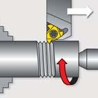
 Thread Turning Technical Data 1 Choose the Thread Turning Method Feed direction towards the chuck was chosen.")
140 Step by Step Thread Turning - Example 1 M40 x.5 Application: Thread: External Right Hand ISO Metric M40x.5 Material: 4140 (5 HRc) Thread Turning Technical Data 1 Choose the Thread Turning Method Feed direction towards the chuck was chosen. Therefore, an external right hand insert and an external right hand holder will be used. Choose the Insert Size Chosen insert: 3ER.5ISO Insert Size mm Pitch mm Ordering Code Anvil Toolholder 3/8.5 3ER.5ISO... E3 A..-3(H) 3 Choose the Toolholder H1 H F 1 B Chosen toolholder: A 5-3 Insert Size Ordering Code 3/8 A 5-3 Dimensions mm H=H1=B F Pitch P* [mm] C-13 Special Toolholders Pitch P* β= [tpi] β= D β= Pitch diameter [mm] From the table, using a pitch of.5 mm (10 tpi) and a workpiece diameter of 40 mm (1.57 ), we find the helix angle to be 1.5.
141 5 Choose the Correct Anvil Anvil chosen: E3 Resultant Helix Angle Insert Size mm Holder Ordering Code 3/8 ER/I E3-P E3-1P E3 E3-1N Choose the Carbide Grade and Cutting Speed Carbide grade chosen: VT Cutting speed: 140 m /min P Material: ow alloy steel (alloying elements 5%) Non hardened Hardened Hardened Hardness Brinell HB VT VCB Thread Turning Tecnical Data 7 Determine the Number of Passes Number of passes: 10 ISO External Pitch mm tpi No. of passes Summary Thread Type Feed Direction: Insert and Grade: Toolholder: Helix Angle: Anvil: Cutting Speed: Number of Passes: ISO M40x.5 External Right Hand Towards the chuck 3ER.5ISO VT A E3 140 m/min 14 C-14
142 Step by Step Thread Turning - Example 5-ACME-3G Application: Thread: Right Hand ACME Pitch: tpi Bore dia: 5 Material: Stainless Steel Austemitic Thread Turning Technical Data 1 Choose the Thread Turning Method To facilitate the removal of chips from the machined area, we chose a feed direction away from the chuck. Therefore, an internal left hand insert and an internal left hand toolholder are to be used. Choose the Insert Size Chosen insert: 4IACME Insert Size Pitch Ordering Code Anvil mm tpi H 1/ 4IACME... E4 Toolholder AVR..-4(H) 3 Choose the Toolholder D1 F 1 D A Chosen toolholder: AVR 40-4H Insert Size Ordering Code Dimensions mm Min Bore A 1 D D1 F mm 1/ AVR Determine the Helix Angle Pitch [mm] Special Toolholders β = - Pitch diameter [mm] D β= β=-1 In this case, a right hand thread is being turned with a left hand toolholder. The reverse helix method is used. From the lower part of the table, using a pitch of tpi and a bore diameter of 17mm, we obtain a helix angle of C-15
143 5 Choose the Correct Anvil Anvil chosen: E4-N Resultant Helix Angle Insert Size 1/ mm 1.5 Ordering Code ER/I E4 E4-1N E4-1.5N E4-N E4-3N Choose the Carbide Grade and Cutting Speed Carbide grade chosen: VT Cutting speed: 140 m /min M Material: Stainless steel Austenitic Austenitic Super austenitic Hardness Brinell HB VT VCB Thread Turning Tecnical Data 7 Determine the Number of Passes Number of passes: 18 ACME External & Pitch mm tpi No. of passes Summary Thread Type Feed Direction: Insert and Grade: Toolholder: Helix Angle: Anvil: Cutting Speed: Number of Passes: 5 x ACME Right Hand Away from the chuck 4IACME VT AVR 40-4H -0.5 E4-N 140 m/min 18 C-
144 Thread Turning Technical Data Material Comparison Table Material Vardex USA Germany Germany Great Britain France Italy Group No. AISI/SAE W.-Nr. DIN BS AFNOR UNI St37- Fe30B E4- Fe30 B FU St44- Fe430B FN E8- Fe430B FN ASTM A570Gr St50- Fe490- FN A50- Fe St70- Fe90- FN A70- Fe C15 080M15 CC1 C15C C 050A0 CC0 C0C C35 00A35 CC35 C C45 080M4 CC45 C C55 070M55 C C0 080A CC55 C SMn8 30M07 S50 CF9SMn SMnPb8 S50Pb CF9SMnPb SPb0 10PbF CF10SPb S0 1M3 35MF SMn3 40M07 S300 CF9SMn SMnPb3 S300Pb CF9SMnPb Si7 50A53 55S7 55Si SiCr7 0SC7 0SiCr Ck15 080M15 C1 C Mn4 150M3 35M Ck Mn5 40M Mn 150M8 0M5 C8Mn Cf35 00A35 C38TS C Ck45 080M4 C4 C Ck55 070M55 C55 C Cf53 00A5 C48TS C Ck0 080A C0 C Ck101 00A Mn1 Z10M1 Z10M1 G10Mn Cr 534A99 100C 100Cr 8 ASTM A0Gr.A Mo D3 Mo3KW Mo Mo5 4 ASTMA350F Ni N 14Ni 8 ASTM A Ni ; Ni Ni19 Z18N NiCr 40A35 35NC NiCr10 14NC11 NiCr ; NiCr14 55M13; 55M1 1NC CrNiMo4 8M40 40NCD3 38NiCrMo4(KB) NiCrMo 805M0 0NCD 0NiCrMo NiCrMo 311-Type7 40NiCrMo(KB) CrNiMo 817M40 35NCD 35NiCrMo(KB) P Steel CrNiMo 80A 18NCD NiCrMo134 83M13 15NiCrMo Cr3 53M15 1C Cr4 530A3 3C4 34Cr4(KB) Cr4 530M40 4C4 41Cr Cr MnCr5 (57M0) MC5 MnCr Cr3 57A0 55C CrMo4 1717CDS110 5CD4 5CrMo4(KB) ; CrMo4 708A37 35CD4 35CrMo ; CrMo4 708M40 4CD4TS 41CrMo CrMo4 708M40 4CD4 4CrMo CrMo5 1CD4 5 ASTM A18; F11; F CrMo Gr.7 15CD3.5; 15CD4.5 14CrMo CrMo1 7M4 30CD1 3CrMo1 5 ASTM A18; F CrMo ; Gr.31; 45 1CD9; 10 1CrMo9, MoV CrV4 735A50 50CV4 50CrV CrAIMo7 905M39 40CAD, 1 41CrAIMo CrMoV M39 3CrMoV1 5 W C105W C98KU; C100KU 5 W C15W 10 C10KU Cr B3 100C 10 D Cr1 BD3 Z00Cr1 10Cr13KU 10 50Cr1KU CrMnMo7 35CrMo8KU CrMnMoS8-10 H CrMoV5-1 BH11 Z38CDV5 37CrMoV51 1KU 10 H CrMoV5-1 BH13 Z40CDV5 35CrMoV05KU 10 40CrMoV511KU 10 A CrMoV5-1 BA Z1 00CDV5 100CrMoV51KU CrMoV5-3 Z38CDV D CrVMo 1-1 BD Z0CDV1 155CrVMo1 1 KU WCr 105WC13 10WCr; 107WCr5KU CrW1 15CrW11KU 10 S WCrV17 BS1 45WCrV8KU 10 H WCrV9 3 BH1 Z30WCV9 30WCrV9 3KU CrMoV1 5CrMoW1KU NiCrMoV 55NCDV CrMnNiMo W V1 BW 1105V; 100V S Z85WDKCV HS T S BT4 Z80WKCV WCo1805KU 10 M S -5- BM Z85WDCV WMo005KU 10 M S -9- Z100WCWV HS T S BT1 Z80WCV W18KU C-17
145 Sweden Japan Russia Spain Vardex SS JIS GOST UNE No STKM 1A;C Fe30B SM400A;B;C St4ps;sp Fe430B FN SS490 St5ps;sp A490- A F C ; F F F F.115 0(G) 191 SUM F SMn SUM F.11-11SMnPb8 1 F.1-10SPb F.10.G F.113-1SMn35 19 F.114-1SMnPb S F Si7 F.144-0SiCr S15C 15 F.1110-C15k ; F.1511-Ck 1 40G S5C 5 F.110-C5k 10 SMn438(H) 35G ; 35G F.103-3Mn ; F.81-3Mn5 SCM1 30G 8Mn 157 S35C 35 7 S45C 45 F.1140-C45k ; F.114-C48k S55C 55 F.1150-C55k 74 S50C S58C 0 ;0G ;0GA SUP4 8 SCMnH/1 110G13 F.851-AM-10Mn SUJ SchCh15 F Cr 8 91 F.01-Mo3 8 F.0-Mo5 8 F.41-15Ni 4 F.45-8Ni SNC3 5 SNC415(H) F NiCr11 5 SNC81 5(H) 5 40ChNMA ; 40ChGNM F NiCrMo SNCM0(H) 0ChGNM F.155-0NiCrMo ; F NiMo31 5 SNCM40 38ChGNM F NiCrMo ; F NiCrMoDF ChNMA F.17-40NiCrMo7 ;34CrNiMo 5 F NiCrMo13 5 F NiCrMo13 ;F NiCrMo131 5 SCr415(H) 15Ch SCr430(H) 35Ch F.81-35Cr4 5 SCr440(H) 40Ch F Cr4DF ; F.10-4Cr SCr440 40Ch F.10-4Cr ChG F.15-MnCr5 ; F.1517-MnCr5 5 SUP9(A) 50ChGA F Cr3 5 5 SCM40 0ChM ; 30ChM F.837-AMCrMo4;F.8330-AM5CrMo4;F.15-30CrMo SCM43; SCCRM3 AS38ChGM;35ChM;35ChM F.8331-AM34CrMo4;F.83134CrMo4;F CrMo4;F CrMo4DF 5 44 SCM440 40ChFA F.833-AM4CrMo4;F.83-4CrMo4;F.15-40CrMo SCM440(H) F.833-AM4CrMo4;F.83-4CrMo4;F.15-40CrMo4 5 SCM415(H) F CrMo4 5 1ChM ; 15ChM F.31-14CrMo F.14.A Ch8 TU.H 5 F.1-13MoCrV 5 30 SUP10 50ChGFA ; 50CHFA F CrV ChMJuA F CrAlMo U10A-1; F.5 5 SK U13 F.513 ; C10 5 Ch F.530 ; 100Cr 8 SKD1 Ch1 F.51 ; 10 Cr SKD 4ChMFS F.5317 ; 37 CrMoV SKD1 4ChMF1S F.5318 ; 40CrMoC SKD1 F.57 ; 100CrMoV SKD11 F.50A SKS31;SKS,SKS3 ChWG F.533 ; 105WCr SKD F.513 ; 10CrW ChWSF F.541 ; 45WCrSi8 10 SKD5 3ChW8F F.533 ; 30WCrV F.511 ; 0CrMoV1 10 SKT4 5ChNM F.50S SKS SKH55 73 RM5K5 10 SKH3 F.5530 ; SKH9 (RAM5) ; RM5 F.503 ; F.507 ; SKH R18 F.550 ; P Thread Turning Tecnical Data C-18
146 Thread Turning Technical Data Material Comparison Table (con t) Material Vardex USA Germany Germany Great Britain France Italy Group No. AISI/SAE W.-Nr. DIN BS AFNOR UNI Cr13 403S17 ZC13 Cr Cr Cr13 410S1 Z10C14 1Cr Cr17 430S15 Z8C17 8Cr G-0Cr14 40C9 Z0C13M Cr13 40S45 Z40CM;Z38C13M 40Cr CrNi17 431S9 Z15CNi.0 CrNi CrMoS17 Z10CF17 10CrS CrMo S17 Z8CD CrMo CrNi134 45C11 Z4CND13.4M G-CrNiMo C 1 HW CrSi93 401S45 Z45CS 9 45CrSi CrAI13 403S17 Z10C13 101CrA CrAI18 430S15 Z1CAS18 8Cr17 1 HNV CrNiSi0 443S5 Z80CSN0.0 80CrSiNi CrAI4 Z10CAS4 Cr CrNi S15 ZCN CrNi CrNiS S1 Z10CNF CrNiS M Stainless Steel K Cast Iron N(K) Non- Ferrous Metals S(M) Heat Resistant Material CrNi S1;304C1 ZCN18.10;Z3CN CrNi CF G-CrNi C15 ZCN18.10M CrNi S1 Z1CN CrNi N CrNiN S ZCN CrNiMo171 3S ZCND CrNiMo N CrNiMoN17133 ZCND CrNiMo S1 ZCND17.13 CrNiMo CrNiMo S1 ZCND19.15 CrNiMo CrNiMo CrNiTi ZCNT18.10 CrNiTi CrNiNb S17 ZCNNb18.10 CrNiNb Ti CrNiMoTi171 30S17 ZNDT1 7.1 CrNiMoTi G-5CrNiMoNb C17 Z4CNDNb18 1M G8CrNiMo CrNiMoNb18 1 ZCNDNb17 13B CrNiMoNb CrNiSi S4 Z15CNS S CrNi S4 Z1CN5 0 CrNi NiCr3 Z1NCS G-40NiCrSi C11 G50NiCr EV CrMnNiN S54;31S1 Z5CMN9 53CrMnNiN CrNiTi S30 ZCNT18.1B CrNiTi No 0 B GG10 Ft 10 D 30 No 5 B GG15 Grade 150 Ft 15 D 30 No 30 B 0.00 GG0 Grade 0 Ft 0 D 9 No 35 B; No 40 B 0.05 GG5 Grade 0 Ft 5 D 9 No 45 B GG30 Grade 300 R 30 D 9 No 50 B GG35 Grade 350 Ft 35 D 9 No 55 B GG40 Grade 400 Ft 40 D 9 ASTM DIN : A43-7 GG- A Type NiCr0 -NiCr 0 -NC GGG 40 SNG 40/1 FCS GS GGG 40.3 SNG 370/17 FGS GGG GGG 50 SNG 500/7 FGS GS GGG 0 SNG 00/3 FGS GGG70 SNG 700/ FGS 700- GS DIN 94 -NM Type GGG NiMn NiMn NC 0 31 GGG NiCr 0 -NC GTS-35 B 340/1 MN GTS-45 P 440/ GTS-55 P 510/4 MP GTS-5 P 570/3 MP GTS-70 P90/ MP 70-3 G-AlSi1 M0 3 GD-AlSi1 3 GD-AlSi8Cu3 M4 3 G-AlSi10Mg M9 3 G-AlSi1 M NiCrSi Z1NCS G-40NiCrSi 330C11 G50NiCr A.403 NCFeD NiCr0Ti HR5, 03-4 NC0T NiCrMo9N NCFeDNB C W.49 CoCr0W15 KC0WN NiCu30Al NiCr0TiAk Hr40,01 NC0TA 19 AMS NiCr19Co11 NC19KDT W.47 S-NiCr13A NC1AD 1 50 W.4 NiCr19Fe19 HR8 NC19FeNb W.4 NiCr19Fe19 NC0K14 1 CoCrW14 KCWN 1 W.47 NiCo15Cr10 3 TiAl14Mo4Sn4Si0.5 3 TiAl5Sn.5 TA14/17 T-A5E 3 TiAlV4 TA10-13/TA T-AV 3 TiAlV4EI TA11 C-19
147 Sweden Japan Russia Spain Vardex SS JIS GOST UNE No. 301 SUS403 08Ch13 F.3110-Cr13 ; F.8401-AM-1Cr Ch13 F.3110-Cr13 ; F.8401-AM-1Cr SUS410 1Ch13 ; 15Ch13 F Cr SUS430 1Ch17 F.3113-Cr17 1 SCS 0Ch SUS40J 40Ch13 F Cr SUS431 0Ch17N F CrNi SUS430F F CrS17 ; F CrMoS SUS434 F.31-CrMo171 1 SCS5 1 SCS14 07Ch18N10GSM F.8414-AM-7CrNiMo010 1 SUH1 40Ch9S F.30-4SCrSi SUS405 10Ch13SJu F CrAl13 1 SUH1 15Ch18SJu F CrAl18 11 SUH4 F.3-80CrSiNi SUH44 F CrAl SUS304 08Ch18N10 F CrNi1811;F CrNi1810 ; F.3504-CrNi SUS303 F CrNiS SCS19; SUS304 03Ch18N11 F.3503-CrNi SCS13 07Ch18N SUS301 F CrNi SUS304N F.3541-CrNiN SUS3 F CrNiMo SUS3N F.3543-CrNiMoN SCS 03Ch17N14M3 F.3533-CrNiMo SUS317 F.3539-CrNiMo SUS39; F CrNiMo7-05; F.355-8CrNiMo 13 58B SUS31 0Ch18N10T ; 08Ch18N10T; 09Ch18N10T; 1Ch18N10T F.353-CrNiTi SUS347 08Ch18N1B F.354-CrNiNb Ch17N13MT F.3535-CrNiMoTi171 1 SCS 1 1 SUH309 0Ch0N14S F CrNiSi SUH310 0Ch3N18 13 SUH330 F CrNiSi3-13 SCH15 13 SUH35,SUH3;SU31 55Ch0G9AN4 F CrMnNiN C 10 FG C 15 FG C 0 FG C 5 FG C 30 FG C 35 FG C 40 9 MB 9 ISO VC VC VC VC VC SUH 330 F CrNiSi3-19 SCH M K N S Thread Turning Tecnical Data C-0


148 Troubleshooting Problem Possible Cause Solution Cutting speed too high Reduce cutting speed/ use coated insert Increased flank wear Depth of cut too low/ too many passes Unsuitable carbide grade Increase the depth of cut per pass Use a coated carbide grade Insufficient cooling Increase coolant flow rate Thread Turning Technical Data Uneven cutting edge wear Incorrect helix angle Wrong infeed method Choose the correct anvil Use the Alternating Flank Infeed method Depth of cut too large Extreme Insufficient cooling plastic Cutting speed too high deformation Unsuitable carbide grade Nose radius too small Decrease depth of cut/ increase number of passes Increase coolant flow rate Reduce cutting speed Use a tougher carbide Use an insert with a larger radius, if possible Cutting edge breakage Depth of cut too large Extreme plastic deformation Insufficient cooling Unsuitable carbide grade Instability Decrease depth of cut/ increase number of passes Use a tougher carbide Increase flow rate and/ or correct flow direction Use a tougher carbide Check stability of the system Built-up edge Incorrect cutting speed Unsuitable carbide grade Change the cutting speed Use a coated carbide Thread profile is too shallow The tool is not at the workpiece axis height Insert is not machining the thread crest Worn insert Change tool height Measure the workpiece diameter Change the cutting edge sooner Poor surface quality Cutting speed too low Wrong anvil Flank infeed method is not appropriate Increase cutting speed Choose correct anvil Use the alternate flank or radial infeed method C-1


149 GROOVING INSERTS
150 GROOVING INSERTS Grooving Inserts VARDE Ordering Code System External - DIN 471 Retaining Ring Grooves for Shafts - DIN 47 Retaining Ring Grooves for Bores - DIN 47 Retaining Ring Grooves for Bores-Micro External/ - DIN 7993 Snap Ring Grooves External/ - DIN 7993 Snap Ring Grooves - Micro External - DIN 7 Thread Undercuts - DIN 7 Thread Undercuts - DIN Grooves - Micro - DIN 471 DIN 47 - Face Grooves - Micro Square Groove - Microscope Round Groove - Microscope Face Groove - Microscope Pre-Part Off - Microscope Page D - Page D - 3 Page D - 4 Page D - 5 Page D - 7 Page D - 8 Page D - 9 Page D -10 Page D -10 Page D -11 Page D -1 Page D -13 Page D -14 Page D -15 D-1
151 Vardex Ordering Code System Grooving Insert 5 1 I 3 R D VKP Insert Size - Insert Style 3 - Type of Insert 4 - / H Insert /4 3-3/8 4-1/ 5-5/8 E - External I - R - Right Hand Insert - eft Hand Insert 5 - Groove Std. Width - Profile Style 7 - Groove Standard 8 - Groove Depth (mm) C - Full profile DIN 471 Partial (mm) DIN 471 DIN 47 Partial DIN 47 DIN 7993 Partial DIN 7993 DIN 7 ST, DIN 7 SH DIN 3770 Grooving Micro Insert - Double Ended 9 - Carbide Grade VT VKP (for Mini) VH (for Mini) Grooving Inserts S I 3 R A - D471/D VM Insert Dia. - Insert Style 3 - Type of Insert 4 - / H Insert 5 - Groove std. Width mm mm mm mm mm S - Micro Insert I - R - Right Hand Insert - eft Hand Insert (mm) - Insert ength 7 - Groove Standard 8 - Groove Depth 9 - Carbide Grade A - Axially S - Short M - Medium - ong DIN 471 DIN 47 DIN 7993 DIN 7SH, DIN7ST DIN3770S, DIN3770D DIN 471/47- Face Grooving (mm) VM Grooving Inserts - Single Ended M GS 4 W R/ 8 VB 9 1- Product ine M - Microscope - Insert Size 4, 5,, Min. Bore dia Type of Application 5- - Width / Radius 7 - Overhang ength 8 - H or 9 - Carbide Grades GS-Grooving Square GR-Grooving Round FG-Face Grooving FP-Face Grooving External PP-Pre Part Off Width Radius -3.0 (mm) 0.5- (mm) R - - H VB D-
152 DIN 471 Retaining Ring Grooves for Shafts External W W t1 t t 45 d1 m Standard (Partial Profile) Standard (Full Profile) Standard (Partial Profile) Insert Size Ordering Code Groove Std. Dimensions mm Anvil Holder m (H13) W t Grooving Inserts 3/8 3ER1.10-D ER1.30-D ER-D ER1.85-D Range of profiles also available on 1/4, 1/ and 5/8, inserts on request E3M-1.5N A..-3 Standard (Full Profile) Insert Size Ordering Code Groove Std. Dimensions mm Anvil Holder m (H13) d1 W t1 t 3ER1.10C-D ER1.10C-D ER1.30C-D ER1.30C-D /8 3ERC-D ERC-D E3M-1.5N A..-3 3ERC-D ER1.85C-D ER1.85C-D ER.15C-D Range of profiles also available on 1/4, 1/ and 5/8, inserts on request. D-3
153 DIN 47 Retaining Ring Grooves for Bores W t1 W t t d1 45 t 5.0 m W Standard (Partial Profile) Standard (Full Profile) Mini- (Partial Profile) Standard (Partial Profile) Insert Size Ordering Code Groove Std. Dimensions mm Anvil Holder m (H13) W t 3/8 3IR1.10-D IR1.30-D IR-D IR1.85-D Range of profiles also available on 1/4, 1/ and 5/8, inserts on request. For minimum bore diameters, refer to page E I3M-1.5N AVR..-3 Grooving Inserts Standard (Full Profile) Insert Size Ordering Code Groove Std. Dimensions mm Anvil Holder m (H13) d1 W t1 t 3IR1.10C-D IR1.30C-D IR1.30C-D /8 3IR1.30C-D IRC-D I3M-1.5N AVR..-3 3IRC-D IR1.85C-D IR.15C-D Range of profiles also available on 1/4, 1/ and 5/8, inserts on request. For minimum bore diameters, refer to page E-. Mini- (Partial Profile) Insert Size Ordering Code Groove Std. Dimensions mm Min. Bore dia (mm) Holder m (H13) W t 5IR0.9-D IR1.1-D NVR IR1.3-D D-4
154 DIN 47 Retaining Ring Grooves for Bores F W d B 1 t m -Double Ended Micro - Double Ended Insert dia. Ordering Code d (mm) Groove Std. m (H13) W Dimensions mm 1 Min. Bore dia. B t F mm Holder Grooving Inserts SIR0.90S-D SIR0.90M-D SIR1.10S-D SIR1.10M-D SIR0.90S-D SIR0.90M-D SMC SIR0.90-D SIR1.10S-D SIR1.10M-D SIR1.10-D SIR1.30S-D SMC SIR1.30M-D SIR1.30-D SIRS-D SIRM-D SIR-D SIR0.90S-D SIR0.90M-D SIR0.90-D SIR1.10S-D SIR1.10M-D SIR1.10-D SIR1.30S-D SIR1.30M-D SIR1.30-D SMC SIRS-D SIRM-D SIR-D SIR1.85S-D SIR1.85M-D SIR1.85-D SIR.15S-D SIR.15M-D SIR.15-D continued on next page D-5
155 DIN 47 Retaining Rings Grooves for Bores (con t) F W d B 1 t m -Double Ended Micro - Double Ended (con t) Insert dia. Ordering Code Groove Std. Dimensions mm Min. Bore dia. d (mm) m (H13) W 1 B t F mm Holder SIR1.10M-D SIR1.30M-D SIRM-D SIR1.85M-D SIR.15M-D SIR.5M-D SMC Grooving Inserts 8.0SIR3.15M-D SIR1.30M-D SIRM-D SIR1.85M-D SIR.15M-D SIR.5M-D SMC SIR3.15M-D SIR4.15M-D SIR5.15M-D D-
156 DIN 7993 Snap Ring Grooves External R W t R Standard (Partial Profile) Standard (Partial Profile for Shafts) Insert Size Ordering Code Dimensions mm Anvil Holder R W t Grooving Inserts 3/8 3ER0.40-D ER0.0-D ER0.90-D ER0-D Range of profiles also available on 1/4, 1/ and 5/8, inserts on request E3M-1.5N A..-3 t W R R t 5.0 R Standard (Partial Profile) W Mini- (Partial Profile) Standard (Partial Profile for Bores) Insert Size Ordering Code Dimensions mm Anvil Holder R W t 3IR0.0-D /8 3IR0.90-D I3M-1.5N AVR..-3 3IR0-D Range of profiles also available on 1/4, 1/ and 5/8 inserts on request. For minimum bore diameters, refer to page E-. Mini- (Partial Profile for Bores) Insert Size Ordering Code Dimensions mm Min. Bore dia Holder R W t mm 5.0 5IR0.4-D IR0.-D NVR10.-5 D-7
157 D-8 Grooving Inserts R DIN 7993 Snap Ring Grooves -Double Ended Insert Dia. Dimensions mm d (mm) W Groove Std Min. Bore dia R Ordering Code R t B F W 1 d Micro (Partial Profile) - Double Ended B t Holder SMC SMC SMC..-.0 SMC SMC SIR0.4S-D SIR0.4M-D SIR0.4S-D SIR0.4M-D SIR0.4-D SIR0.S-D SIR0.M-D SIR0.-D SIR0.9S-D SIR0.9M-D SIR0.9-D SIR0.9S-D SIR0.9M-D SIR0.9-D SIRS-D SIRM-D SIR-D SIR1.1S-D SIR1.1M-D SIR1.1-D SIR0.9M-D SIR1.1M-D SIR1.4M-D SIR1.4M-D SIR1.8M-D F mm
158 DIN 7 Thread Undercuts (For ISO Metric Threads in Accordance with DIN 13) External t R 30 min R g1 R t1 R g1 R t R g Normal - Type A Short - Type B Grooving Inserts Standard (Normal - Type A) Insert Size Ordering Code Pitch Dimensions mm Anvil Holder 3/8 5/8 3ER0.50-D7ST ER0.0-D7ST ER0.70-D7ST ER0.80-D7ST ER0-D7ST ER1.5-D7ST ER1.50-D7ST ER1.75-D7ST ER.00-D7ST mm R g g t t E3M-1.5N E5M-1.5N A..-3 A..-5 Standard (Short - Type B) Insert Size Ordering Code Pitch Dimensions mm Anvil Holder 3/8 5/8 3ER0-D7SH ER1.5-D7SH ER1.50-D7SH ER1.75-D7SH ER.00-D7SH ER.50-D7SH ER3.00-D7SH mm R g Range of profiles also available on 1/4 and 1/ inserts on request. g t t E3M-1.5N E5M-1.5N A..-3 A..-5 D-9
159 DIN 7 Thread Undercuts (For ISO Metric Threads in Accordance with DIN 13) t R t1 R R g1 t1 R g1 R R 30 min g1 g Normal - Type C Short - Type D Standard (Normal - Type C) Insert Size Ordering Code Pitch Dimensions mm Anvil 3/8 3IR0.50-D7ST IR0.0-D7ST IR0.70-D7ST IR0.80-D7ST IR0-D7ST Range of profiles also available on 1/4, 1/ and 5/8 inserts on request. For minimum bore diameters, refer to page E-. Standard (Short - Type D) mm R g1 g t t I3M-1.5N Insert Size Ordering Code Pitch Dimensions mm Anvil 3/8 3IR0-D7SH IR1.5-D7SH IR1.50-D7SH IR1.75-D7SH mm R g1 g t t Range of profiles also available on 1/4, 1/ and 5/8 inserts on request. For minimum bore diameters, refer to page E-. I3M-1.5N Holder AVR..-3 Holder AVR..-3 Grooving Inserts DIN Grooves F W d B 1 t m -Double Ended Micro - Double Ended Insert dia. Ordering Code d (mm) Groove Std. m (H13) W Dimensions mm 1 Min. Bore dia. B t F mm Holder.0SIR1.S-D3770S SIR1.M-D3770S SIR1.-D3770S SIR.0S-D3770D SMC SIR.0M-D3770D SIR.0-D3770D D-10
160 DIN 471 DIN 47 - Face Grooves W m Outer grv. Ø Inner grv. Ø F t d -Double Ended Micro (Partial Profile) - Double Ended Insert Dia. d (mm) Ordering Code Groove Std. m (H13) W Dimensions mm t F Sleeve Inner Groove Ø Outer Groove Ø Grooving Inserts SIR0.7A-D471/ SIR0.8A-D471/ SIR0.9A-D471/ SIR1.1A-D471/ SIR1.3A-D471/ SIR1.A-D471/ SMC SIR0.7A-D471/ SIR0.8A-D471/ SIR0.9A-D471/ SIR1.1A-D471/ SIR1.3A-D471/ SMC SIR1.A-D471/ SIR1.85A-D471/ SIR.15A-D471/ SIR1.1A-D471/ SIR1.3A-D471/ SIR1.A-D471/ SIR1.85A-D471/ SMC SIR.15A-D471/ SIR.5A-D471/ SIR1.3A-D471/ SIR1.A-D471/ SIR1.85A-D471/ SIR.15A-D471/ SIR.5A-D471/ SMC SIR3.15A-D471/ SIR4.15A-D471/ D-11
161 +_
162 +_
163 +_ +_
164 Parting Off +_


165
166
167
168

169
170

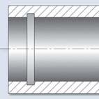


171
172


173 BORING INSERTS
174 BORING INSERT VARDE Ordering Code System CD0W Inserts TD0W Inserts WC0W Inserts Boring - Micro Boring - Microscope Copy - Micro Chamfer - Micro ong Nose - Micro ong Nose - Microscope Back Edge - Micro Boredrill - Micro Page G- Page G-3 Page G-3 Page G-4 Page G-5 Page G- Page G-7 Page G-7 Page G-8 Page G-8 Page G-9 Page G-9 Boring Inserts G-1
175 Vardex Ordering Code System PowerBore Inserts T 1 D 0 3 W VT Insert Shape - Clearance Angle 3 - Tolerance Class 4 - Insert Type C - Diamond 80 deg. T - Triangle W - Trigon 80 deg. C - 7 deg. D - 15 deg. 0 - Special Tolerance Class W - Hole + Countersink 5 - Insert Dimension Thickness-mm Thickness-1.19mm Thickness-1.57mm Thickness-.44mm - Corner Radius 11- R R R R Carbide Grade VT Micro Boring Inserts - Double Ended.0 1 S I 3 R M - Bore VM Insert Dia. - Tool Group 3 - Type of Insert 4 - Hand of Insert 5 - Corner Radius S - Solid Carbide I - R - Right Hand Insert - eft Hand Insert 0. - Tool ength 7 - Tool Application 8 - Front Relief 9 - Carbide Grade S - Short M - Medium - ong Bore - Boring Copy - Boring Copy Chamfer - Boring Chamfer Back - Back Edge 357, 3537, ong Nose BD - Bore Drill 1 - With Relief 0 - Without Relief VM M Inserts - Single Ended BC 4 R R/ 8 VB 9 Boring Inserts 1 - Product ine - Insert Size 3 - Min. Bore dia. 4 - Type of Application 5- - Nose Radius M- Microscope 4, 5,, BC - Boring C - Copy ong Nose 0.1, 0.15, 0. (mm) 7 - Overhang ength or H R - - H 9 - Carbide Grade VB G-
![Boring T R 15 CD0W CD0W Inserts Insert Size Ordering Code R Dimensions [mm] T](/docs-images/92/110809794/images/176-0.jpg "Insert Screw CD0W4011... 0.05.15 CD0W401... 0.18 VS01 CD0W4014... 0.38 T R 15 TD0W TD0W Inserts Boring Inserts Insert Size.")

176 Boring T R 15 CD0W CD0W Inserts Insert Size Ordering Code R Dimensions [mm] T Insert Screw CD0W CD0W VS01 CD0W T R 15 TD0W TD0W Inserts Boring Inserts Insert Size.0 Ordering Code TD0W TD0W TD0W R Dimensions [mm] T Insert Screw VS01, VS40 G-3
177 Boring T R 7 WC0W 413, 414 WC0W Inserts Insert Size Ordering Code R Dimensions mm T Insert Screw.15 WC0W WC0W VS40 T R 7 WC0W 5013, 5014 WC0W Inserts Insert Size.187 Ordering Code WC0W WC0W R Dimensions mm T Insert Screw VS41 Boring Inserts G-4
178 Micro Boring - Boring F R S 1 d -Double Ended Micro - Double Ended Insert dia. d (mm) Ordering Code R 1 Dimensions mm S F Min. Bore Dia. mm Holder SIR0.1US-Bore SIR0.1S-Bore SIR0.S-Bore SIR0.M-Bore SMC SIR0.S-Bore SIR0.M-Bore SMC SIR0.-Bore SIR0.S-Bore SIR0.M-Bore SMC SIR0.-Bore SIR0.S-Bore SIR0.M-Bore SMC SIR0. -Bore SIR0.S-Bore SIR0.M-Bore SMC SIR0.-Bore Boring Inserts G-5
179 Micro Boring - Boring 8 0 d F 1 R S max -Single Ended Micro - Single Ended Insert dia. Ordering Code Dimensions mm Min. Bore dia. d (mm) / H R 1 S max F mm Holder M417BC R10 09R/ M4BC R10 09R/ M4BC R10 14R/ M43BC R15 10R/ M43BC R15 R/ M43BC R15 0R/ MHC..-4 M44BC R15 10R/ 10 8 M44BC R15 R/ M44BC R15 1R/ M44BC R15 R/ 45 M55BC R0 10R/ M55BC R0 R/ M55BC R0 1R/ M55BC R0 R/ MHC..-5 M55BC R0 30R/ M55BC R0 35R/ 35 0 MBC R0 R/ 4 MBC R0 1R/ MBC R0 R/ MBC R0 30R/ MHC..- MBC R0 35R/ MBC R0 40R/ M77BC R0 5R/ M77BC R0 35R/ M77BC R0 40R/ M77BC R0 45R/ MHC..-7 Boring Inserts M77BC R0 50R/ 50 7 Microscope eft-handed tools available upon request (Example: M417BC R ) G-
180 Micro Boring Copy F 5 R S 1 d -Double Ended Micro - Double Ended Insert dia. d (mm) Ordering Code R 1 Dimensions mm S F Min. Bore Dia. mm Holder 4.0SIR0.S-Copy SIR0.M-Copy SIR0.-Copy SMC SIR0.S-Copy SIR0.M-Copy SMC SIR0.-Copy Micro Boring Chamfer F 90 1 d R S S1 -Double Ended Boring Inserts Micro - Double Ended Insert dia. Ordering Code d (mm) R 1 Dimensions mm F S1 S Min. Bore Dia. mm Holder 4.0SIR0.S-Chamfer SIR0.M-Chamfer SMC SIR0.-Chamfer SIR0.S-Chamfer SIR0.M-Chamfer SMC SIR0.-Chamfer G-7
181 Micro Boring - ong Nose 35 R F S 1 d -Double Ended Micro - Double Ended Insert dia. Ordering Code Dimensions mm Min. Bore dia. Toolholder d (mm) R 1 S F mm SIR0.S SIR0.M SIR SIR0.S SIR0.M SIR SIR0.S SIR0.M SIR SMC SMC SMC Micro Boring - ong Nose 47º 1 d 3º Micro - Single Ended F -Single Ended S max R Insert dia. Ordering Code Dimensions mm Min. Bore dia. Toolholder d (mm) /H R 1 S max F mm 4.0 M44C R15 10R/ M44C R15 R/ M44C R15 1R/ MHC M55C R0 R/ M55C R0 5R/ MHC MC R0 R/ MC R0 1R/ MC R0 30R/ MHC..- Microscope eft-handed tools available upon request (Example: M44C R15 10) Boring Inserts G-8
182 Micro Boring - Back Edge A 7 O W F R d S S1 1 W1 min. width -Double Ended Micro - Double Ended Insert dia. Ordering Code d (mm) R 1 A W Dimensions mm W1 S S1 F Min. Bore Dia. mm Holder SIR0.S-Back SIR0.M-Back SMC SIR0.S-Back SIR0.M-Back SMC SIR0.-Back SIR0.S-Back SIR0.M-Back SMC SIR0.-Back Micro Boring - Boredrill D Hole hole A R0. 1 d Boring Inserts Micro - Double Ended Insert dia. Ordering Code d (mm) 1 Dimensions mm -Double Ended A Min. Bore Dia. mm Holder SIR0.M-BD SMC SIR0.M-BD SIR0.-BD SMC SIR0.S-BD SIR0.M-BD SMC SIR0.-BD G-9

183
184
185
186
187
188
189
190


191 BORING TECHNA DATA
192 BORING TECHNA DATA Spare Parts PowerBore Recommended Cutting Data - PowerBore and Micro Grades and Their Applications Page I-1 Page I- Page I- Spare Parts PowerBore Insert Boring Bar Insert Torx Screw Screw Description Torx Key A CD0W VS Oval.77G. B TD0W Min. Bore 7.1 > Bore 7.1 VS01 VS Oval.77G. M G. VT51 E WC0W413, WC0W414 VS40 M G. Boring Technical Data I-1 F WC0W5013, WC0W5014 VS41 M G.
193 Recommended Grades, Cutting Speeds Vc [m/min], Feed f [mm/rev] and Max Depth [mm] Material Group Vardex No. Material Hardness Brinell HB Vc [m/min] Coated VT (PowerBore) VM/VB (Micro & Microscope) Feed [mm/rev] Max Depth [mm] PowerBore Power Micro / CD0W TD0W WD0W Micro / Bore Microscope Microscope 1 ow carbon (C= %) Unalloyed steel Medium carbon (C= %) P Steel ow alloy steel (alloying elements 5%) High alloy steel (alloying elements>5%) High Carbon (C= %) Non hardened Hardened Hardened Annealed Hardened Cast steel ow alloy (alloying elements <5%) High alloy (alloying elements >5%) M Stainless Steel Stainless steel Feritic Stainless steel Austenitic Stainless steel Cast feritic Non hardened Hardened Austenitic Super Austenitic Non hardened Hardened Stainless steel Cast austenitic Austenitic Hardened K Cast Iron 8 Malleable 9 Cast iron 30 Grey 31 Cast iron 3 Nodular SG iron 33 Ferritic (short chips) Pearlitic (long chips) ow tensile strength High tensile strength Feritic Pearlitic N(K) Non-Ferrous Metals 34 Aluminium alloys 35 Wrought 3 Aluminium alloys Aluminium alloys Non aging Aged Cast Cast & aged Cast Si 13-% Copper and copper alloys Brass Bronze and non leaded copper Annealed (Iron based ) S(M) Heat Resistant Material 0 High temperature 1 alloys 3 Titanium alloys 4 Aged (Iron based) Annealed (Nickel or Cobalt based) Aged (Nickel or Cobalt based) Pure 99.5 Ti α+β alloys Rm 1050Rm H(K) Hardened Material 5 Extra hard steel Hardened & tempered 45-50HRc 51-55HRc Grades and Their Applications VT VM VB General use carbide grade. TiAlN coated. General use carbide grade for Micro inserts. TiN coated General use carbide grade for Microscope inserts. TiCN coated I- Boring Technical Data
194 Boring Technical Data I-3

195 MIING thread milling standard mitm tmsd solid carbide groove milling

 Thread Milling Software Using the VARDE")
196 Thread Milling MIING Threading A Tool for Every Thread Milling Job Thread Milling Method Tooling Recommendation for Given Thread Specification Thread Milling Inserts Thread Milling Holders Thread Milling Technical Data MiTM Inserts MiTM Toolholders and Tooling Recommendation MiTM Technical Data TMSD Inserts TMSD Toolholders and Tooling Recommendation TMSD Technical Data TM Solid Carbide TM Solid Carbide Technical Data Grooving Grooving Milling Inserts Grooving Milling Holders Grooving Milling Technical Data Page J- Page J- 3 Page J- 4 Page J-15 Page K-1 Page -1 Page M- Page M-7 Page M-1 Page N-3 Page N-4 Page N- Page O-3 Page O-8 Page P- Page P-5 Page P-7 VARGUS TM Gen CD for CNC Programming (Compatible with Windows 95 and Up, Windows NT) Thread Milling Software Using the VARDE Thread Milling system is simple. Vargus has developed a multi-lingual CD for CNC programming software. All the operator has to do is enter the basic thread parameters and then follow the computer instructions, which lead the operator to the correct choice of tool for the job on hand. The software will then generate the helical interpolation for the CNC program. It couldn t be simpler! J-1 Software and updated versions can be downloaded from
 Thread Milling Short Thread ong Thread Extra ong Thread Extra ong Thread Short & ong Threads TMSC TMC TMSD TMSD Shell Mill From Pitch 0.35mm (80 TPI) Up to 98.0mm (3.8\") Up to 144mm (5.")
 TMVC ong Inserts Offset Inserts Fewer Cycles BTMC...-B TMOC Up to 38.9mm (1.53\") Effective length up to 50.8mm (.")
197 A Tool for EVER Thread Milling Job! Regular Threads Standard Thread Conical Thread TMC TMNC From M15x (9/ x3un) From 1/4 x18npt Coarse Pitch TMC/14... From M10x0.75 (7/ x0unf) Thread Milling Short Thread ong Thread Extra ong Thread Extra ong Thread Short & ong Threads TMSC TMC TMSD TMSD Shell Mill From Pitch 0.35mm (80 TPI) Up to 98.0mm (3.8") Up to 144mm (5.7") Up to 00mm (7.88") Fine arge - Multi Tooth arge - Single Point Small & arge Pitches From pitch 0.35mm (80 TPI) TMC Up to ISO.0 (4UN) BTMC...-B Up to ISO.0 (4UN) TMVC ong Inserts Offset Inserts Fewer Cycles BTMC...-B TMOC Up to 38.9mm (1.53") Effective length up to 50.8mm (.0") Multi-Flute for Faster Machining Small & Medium Diameter Up to 5 flutes MITM Medium Diameter flutes TM arge Diameter Up to 9 flutes Shell Mill arge Diameter Up to 8 flutes MiTM Shell Mill Indexable Inserts Extremely Small Threads ong Thread Small Thread Diameters TMMC Millipro Millipro HD From M10x0.75 (7/ x3un) From M1.x0.35 (1-7UNF) Up to HRc Normal Use Heavy Duty Straight Flutes Helicool From M4.5x0.75 (No.8-3UNF) From M3x0.5 (No.10-3UNF) Helicool+Chamfer Economical Tool TM Solid Deep Threading From Mx1, Max thread length 3mm (.3") Radial Coolant Helicool-R (HCR) From Mx Drill, Thread and Chamfer Helicool-C (HCC) Helical HTC From Mx From M3x0.5 (No.8-3UNF) From Mx J-
198 Thread Milling Thread Milling Methods External Right Hand Thread - Conventional Milling Right Hand Thread - Conventional Milling eft Hand Thread - Conventional Milling eft Hand Thread - Conventional Milling Right Hand Thread - Climb Milling Right Hand Thread - Climb Milling eft Hand Thread - Climb Milling eft Hand Thread - Climb Milling J-3
199 Tooling recommendation* (For MiTM tools see page M-1) (For TMSD tools see page N-1) (For TM Solid Carbide tools see page O-1) ISO - TM Gen Software and updated versions can be downloaded from Thread Milling Pitch mm Nominal Dia. mm Holder Insert 1-Toolholder Overhang D-Tool Cutting dia.* hmin. - Thread Profile depth TMMC1-.0 TMMC1-.0.0I0.75ISOTM...08/001.0I0.75ISOTM TMMC1-.0.0IISOTM TMC1- IISOTM TMC-3 BTMC0-3B 3IISOTM... 3BIISOTM TMC0-3 3IISOTM TMC5-3 3IISOTM TMC5-3 3IISOTM TMMC1-.0 TMMC1-.0.0I1.5ISOTM...08/00.0I1.5ISOTM TMMC1-.0.0I1.5ISOTM TMC1- I1.5ISOTM TMC-3 3I1.5ISOTM BTMC0-3B 3BI1.5ISOTM TMC0-3 3I1.5ISOTM TMC5-3 TMC5-3 3I1.5ISOTM... 3I1.5ISOTM TMC5-5 5I1.5ISOTM TMC3-5 5I1.5ISOTM TMC3-5 5I1.5ISOTM TMSH-D I1.5ISOTM TMSH-D3--5 5I1.5ISOTM TMMC /003.0I1.75ISOTM...08/ TMC1- I.0ISOTM...08/ TMNC-3 3I.0ISOTM TMC-3 3I.0ISOTM BTMC0-3B 3BI.0ISOTM TMC0-3 3I.0ISOTM TMC5-3 3I.0ISOTM TMC5-3 3I.0ISOTM TMC5-5 5I.0ISOTM TMC3-5 5I.0ISOTM TMC3-5 5I.0ISOTM TMSH-D I.0ISOTM TMSH-D3--5 5I.0ISOTM TMSH-D I.0ISOTM TMSH-D I.0ISOTM TMSH-D I.0ISOTM TMC-3 14/001 TMC5-4 14/00 3I.5ISOTM...08/005 4I.5ISOTM...08/ D * The recommended holder is the largest for the given thread specification. Holder with smaller or equal cutting diameters (D ) can also be used (Except inserts 08/...). ** For External Applications = Thread Nominal Dia. = 0.75 minimum Tool Cutting Dia. (D) J-4
200 Thread Milling Tooling recommendation (con t)* (For MiTM tools see page M-1) (For TMSD tools see page N-1) (For TM Solid Carbide tools see page O-1) TM Gen Software and updated versions can be downloaded from ISO - (con t) Pitch mm Nominal Dia. mm Holder Insert 1-Toolholder Overhang D-Tool Cutting dia.* hmin. - Thread Profile depth 4-33 TMC5-4 14/00 4I3.0ISOTM...08/ TMC5-5 5I3.0ISOTM...08/ TMC5-5 5I3.0ISOTM TMC3-5 5I3.0ISOTM TMC3-5 5I3.0ISOTM TMSH-D3--5 5I3.0ISOTM TMSH-D I3.0ISOTM TMSH-D I3.0ISOTM TMSH-D I3.0ISOTM TMC5-5 14/004 5I3.5ISOTM...08/ TMC5-5 5I4.0ISOTM...08/ TMC5-5 5I4.0ISOTM TMC3-B BI4.0ISOTM TMC3-5 5I4.0ISOTM TMC40-B TMC40-B BI4.0ISOTM... BI4.0ISOTM TMSH-D3--B BI4.0ISOTM TMSH-D80-7-B BI4.0ISOTM TMSH-D100-3-B BI4.0ISOTM TMSH-D15-40-B BI4.0ISOTM TMC5-5 5I4.5ISOTM...08/ TMC5-5 TMC3-B 5I5.0ISOTM...08/075 BI5.0ISOTM TMC3-B TMC40-B BI5.5ISOTM... BI5.5ISOTM TMC40-B BI.0ISOTM TMC40-B BI.0ISOTM TMSH-D3--B TMSH-D80-7-B BI.0ISOTM... BI.0ISOTM TMSH-D100-3-B BI.0ISOTM TMSH-D15-40-B BI.0ISOTM D * The recommended holder is the largest for the given thread specification. Holder with smaller or equal cutting diameters (D ) can also be used (Except inserts 08/...). J-5 ** For External Applications = Thread Nominal Dia. = 0.75 minimum Tool Cutting Dia. (D)
201 Tooling recommendation (con t)* (For MiTM tools see page M-1) (For TMSD tools see page N-1) (For TM Solid Carbide tools see page O-1) UN - TM Gen Software and updated versions can be downloaded from Thread Milling Pitch tpi Nominal Dia. Inch Holder Insert 1-Toolholder Overhang D-Tool Cutting dia.* hmin. - Thread Profile depth 7/-1/ TMMC1-.0.0I3UNTM /-11/ TMC1- I3UNTM /4-13/ TMC-3 3I3UNTM /8-15/ TMC0-3 3I3UNTM TMC5-3 3I3UNTM /-1/ TMMC1-.0.0I8UNTM /-3/4 TMC1- I8UNTM /-7/8 15/ TMC-3 TMC0-3 3I8UNTM... 3I8UNTM /8 TMC5-3 3I8UNTM /-1 1/ TMC5-3 3I8UNTM /-11/ TMC1- I4UNTM / TMMC1-.0.0I0UNTM...08/ /-9/ TMMC1-.0.0I0UNTM /8-13/ TMC1- I0UNTM /8 TMC-3 3I0UNTM /-1 TMC0-3 3I0UNTM /-1 1/8 1 3/-1 5/ TMC5-3 TMC5-3 3I0UNTM... 3I0UNTM /8-1 5/8 TMC5-5 5I0UNTM /-1 13/ TMC3-5 5I0UNTM /8-1/8 TMC3-5 5I0UNTM /4-5/8 TMSH-D I0UNTM /4-3 TMSH-D3--5 5I0UNTM / TMC1- I18UNTM...08/ /8 TMC1- I18UNTM /-1 3/ 1 1/4-1 3/8 TMC5-3 TMC5-3 3I18UNTM... 3I18UNTM /-1 5/8 TMC5-5 5I18UNTM / TMC3-5 5I18UNTM /-5/8 TMMC1-.0.0IUNTM...08/ /-13/ TMC1- IUNTM /8-15/ TMC-3 3IUNTM TMC0-3 3IUNTM /-1 3/ TMC5-3 3IUNTM /4-1 3/8 TMC5-3 3IUNTM /-1 5/8 TMC5-5 5IUNTM /-1 7/8 TMC3-5 5IUNTM /- 3/ TMC3-5 5IUNTM /4-5/8 TMSH-D IUNTM /4-3 3/8 TMSH-D3--5 5IUN TM D * The recommended holder is the largest for the given thread specification. Holder with smaller or equal cutting diameters (D ) can also be used (Except inserts 08/...). ** For External Applications = Thread Nominal Dia. = 0.75 minimum Tool Cutting Dia. (D) J-
202 Thread Milling Tooling recommendation (con t)* (For MiTM tools see page M-1) (For TMSD tools see page N-1) (For TM Solid Carbide tools see page O-1) TM Gen Software and updated versions can be downloaded from UN - (con t) Pitch tpi Nominal Dia. Inch Holder Insert 1-Toolholder Overhang D-Tool Cutting dia.* hmin. - Thread Profile depth 3 1/-4 TMSH-D IUNTM / 7/8 TMMC /003 TMC1-.0I14UNTM...08/013 I14UNTM / TMC0-14/005 I13UNTM...08/ /-11/ TMC0-14/005 I1UNTM...08/ /4 TMNC-3 3I1UNTM...08/ / TMC-3 3I1UNTM...08/ /8 TMNC-3 3I1UNTM / TMC-3 3I1UNTM BTMC0-3B 3BI1UNTM / 1 1/8-1 1/4 TMC0-3 TMC5-3 3 I1UNTM... 3I1UNTM /-1 7/ TMC5-3 3 I1UNTM /-1 11/ TMC5-5 5I1UNTM /4-1 15/ TMC3-5 5I1UNTM /4 TMC3-5 5I1UNTM /8-3/4 TMSH-D I1UNTM /8-3 3/8 TMSH-D3--5 5I1UNTM /-4 TMSH-D I1UNTM /8 TMC0-14/00 I11UNTM...08/ /4 TMC-3 14/001 3I10UNTM...08/ /8 TMC5-4 14/00 4I9UNTM...08/ / TMC5-4 14/007 4I8UNTM...08/ /4-1 3/8 TMC5-5 14/004 5I8UNTM...08/ /-1 5/8 TMC5-5 5I8UNTM...08/ /-1 15/ - 1/8 TMC5-5 TMC3-5 5I8UNTM... 5I8UNTM /4-7/8 TMC3-5 5I8UNTM /8 TMSH-D3--5 5I8UNTM /4-4 TMSH-D I8UNTM /8-1 1/4 TMC5-4 14/00 4I7UNTM...08/ /8-1 9/ TMC5-5 14/004 5IUNTM...08/ /8-1 15/ TMC5-5 5IUNTM...08/ /8 TMC5-5 5IUNTM /4 TMC3-5 5IUNTM /8-1/ TMC40-B BIUNTM /8-3 1/8 TMC40-B BIUNTM /4-3 3/4 TMSH-D3--B BIUNTM /8-4 TMSH-D80-7-B BIUNTM /4 TMC5-5 5I5UNTM...08/ /4 TMC3-B BI4.5UNTM / TMC40-B BI4UNTM /4-3 TMC40-B BI4UNTM /4-4 TMSH-D3--B BI4UNTM D * The recommended holder is the largest for the given thread specification. Holder with smaller or equal cutting diameters (D ) can also be used (Except inserts 08/...). J-7 ** For External Applications = Thread Nominal Dia. = 0.75 minimum Tool Cutting Dia. (D)
203 Tooling recommendation (con t)* (For MiTM tools see page M-1) (For TMSD tools see page N-1) (For TM Solid Carbide tools see page O-1) UNJ - TM Gen Software and updated versions can be downloaded from Thread Milling Pitch tpi Nominal Dia. Inch Holder Insert 1-Toolholder Overhang D-Tool Cutting dia.* hmin. - Thread Profile depth 4 9/-11/ TMC1- I4UNJTM / TMMC1-.0.0I0UNJTM /4-13/ 7/8 TMC1- TMC-3 I0UNJTM... 3I0UNJTM /-1 TMC0-3 3I0UNJTM /8 TMC1- I18UNJTM /-1 3/ TMC5-3 3I18UNJTM /4-1 11/ TMC5-3 3I18UNJTM /-13/ TMC1- IUNJTM /8-15/ TMC-3 3IUNJTM TMC0-3 3IUNJTM /-1 3/ TMC5-3 3IUNJTM /4-1 3/8 1 7/-1 5/8 TMC5-3 TMC5-5 3IUNJTM... 5IUNJTM /-1 7/8 TMC3-5 5IUNJTM /- 1/8 TMC3-5 5IUNJTM /4-3/8 TMSH-D IUNJTM /8 TMC1- I14UNJTM /8 TMNC-3 3I1UNJTM /-1 TMC-3 3I1UNJTM / TMC0-3 3I1UNJTM /8-1 1/4 TMC5-3 3I1UNJTM /-1 7/ TMC5-3 3I1UNJTM /-1 11/ TMC5-5 5I1UNJTM /4-1 15/ TMC3-5 5I1UNJTM /4 TMC3-5 5I1UNJTM /8-3/4 TMSH-D I1UNJTM /8-3 3/8 TMSH-D3--5 5I1UNJTM /-4 1/4 TMSH-D I1UNJTM /8-5 1/4 TMSH-D I1UNJTM /8- TMSH-D I1UNJTM D * The recommended holder is the largest for the given thread specification. Holder with smaller or equal cutting diameters (D ) can also be used (Except inserts 08/...). ** For External Applications = Thread Nominal Dia. = 0.75 minimum Tool Cutting Dia. (D) J-8
204 Thread Milling Tooling recommendation (con t)* (For MiTM tools see page M-1) (For TMSD tools see page N-1) (For TM Solid Carbide tools see page O-1) W - TM Gen Software and updated versions can be downloaded from Pitch tpi Nominal Dia. Inch Holder Insert 1-Toolholder Overhang D-Tool Cutting dia.* hmin. - Thread Profile depth 7/ TMMC1-.0.0IWTM...08/ /-9/ TMMC1-.0.0EIWTM /8-3/4 TMC1- EIWTM /-7/8 TMC-3 3EIWTM /-1 TMC0-3 3EIWTM /-1 1/8 TMC5-3 3EIWTM /-1 5/8 TMC5-3 3EIWTM /4- TMSH-D38-- EIWTM / TMMC1-.0.0I0WTM...08/ / TMMC1-.0.0EI0WTM /8-13/ TMC1- EI0WTM /8-15/ TMC-3 3EI0WTM /-1 3/ TMC0-3 TMC5-3 3EI0WTM... 3EI0WTM /4-1 5/8 TMC5-3 3EI0WTM /4-1/8 TMSH-D38-- EI0WTM /4-3 TMSH-D EI0WTM / TMMC1-.0.0I18WTM...08/ / TMC0-14/005 IWTM...08/ /-3/4 TMC1- IWTM...08/ / TMNC-3 3EIWTM /8-15/ TMC-3 3EIWTM / TMC0-3 3EIWTM /8-1 1/4 TMC5-3 3EIWTM /-1 3/ /8 TMC5-3 TMC5-5 3EIWTM... 5EIWTM /4-1.9 TMC3-5 5EIWTM /4 TMC3-5 5EIWTM /8-3/4 TMSH-D EIWTM /8-3 3/8 TMSH-D3--5 5EIWTM /-4 1/8 TMSH-D EIWTM /4-5 1/8 TMSH-D EIWTM /4-7 TMSH-D EIWTM /8-11/ TMC0-14/00 I14WTM..08/ /4 TMC-3 14/001 3I1WTM...08/ / TMC-3 3I1WTM...08/ /-1 5/ TMC0-3 3I1WTM...08/ /8-1 7/ TMC5-5 5I1WTM...08/ /-1 3/4 TMC5-5 5EI1WTM /8 TMC3-5 5EI1WTM /4 TMC3-5 5EI1WTM D * The recommended holder is the largest for the given thread specification. Holder with smaller or equal cutting diameters (D ) can also be used (Except inserts 08/...). J-9 ** For External Applications = Thread Nominal Dia. = 0.75 minimum Tool Cutting Dia. (D)
205 Tooling recommendation (con t)* (For MiTM tools see page M-1) (For TMSD tools see page N-1) (For TM Solid Carbide tools see page O-1) TM Gen Software and updated versions can be downloaded from Thread Milling W - (con t) Pitch tpi Nominal Dia. Inch Holder Insert 1-Toolholder Overhang D-Tool Cutting dia.* hmin. - Thread Profile depth 3/8-3/4 TMSH-D EI1WTM /8-3 3/8 TMSH-D3--5 5EI1WTM /-4 1/8 TMSH-D EI1WTM /4-5 1/8 TMSH-D EI1WTM /4-7 TMSH-D EI1WTM /8 TMC5-4 14/00 4I11WTM...08/ TMC5-4 14/00 4I10WTM...08/ /8-1 1/4 TMC5-4 14/00 4I9WTM...08/ TMC5-4 14/00 4I8WTM...08/ /-1.4 TMC5-5 14/004 5I8WTM...08/ /-1 5/8 TMC5-5 5I8WTM...08/ /8-1.9 TMC5-5 5EI8WTM /8 TMC3-5 5EI8WTM /4-3 TMC3-5 5EI8WTM /8-3 5/8 TMSH-D3--5 5EI8WTM /4-4 3/8 TMSH-D EI8WTM /8-5 1/ TMSH-D EI8WTM /8-7 TMSH-D EI8WTM /8 TMC5-5 14/008 5I7WTM...08/ /4 1 3/4 TMC5-5 14/004 TMC5-5 5I7WTM...08/048 5I7WTM...08/ TMC5-5 5EI7WTM /-1 1/ TMC5-5 14/004 5IWTM...08/ /8 TMC5-5 5IWTM...08/ /8-1.9 TMC3-5 5IWTM...08/ /8 TMC5-5 5EIWTM /4 TMC3-B BEIWTM /8-. TMC3-5 5EIWTM /8-3/4 TMC40-B BEIWTM /8-3 1/4 TMC40-B BEIWTM /8-3 7/8 TMSH-D3--B BEIWTM /4 TMSH-D80-7-B BEIWTM /8-5 3/4 TMSH-D100-3-B BEIWTM /8-7 TMSH-D15-40-B BEIWTM /4 TMC40-B TMC40-B BEI5WTM... BEI5WTM / 3 3/4-4 TMC40-B TMC40-B BEI4.5WTM... BEI4.5WTM D * The recommended holder is the largest for the given thread specification. Holder with smaller or equal cutting diameters (D ) can also be used (Except inserts 08/...). ** For External Applications = Thread Nominal Dia. = 0.75 minimum Tool Cutting Dia. (D) J-10
206 Thread Milling Tooling recommendation (con t)* (For MiTM tools see page M-1) (For TMSD tools see page N-1) (For TM Solid Carbide tools see page O-1) BSP - Pitch tpi Nominal Dia. Inch 1/4 3/8 1/-5/8 3/4-7/ /4-1 1/ 1 3/4-1/4 1/-3 3 1/ 4 5- Holder TMMC0-.0 TMC0- TMC0- TMC-3 TMC5-5 14/004 TMC5-5 TMC3-5 TMC3-5 TMSH-D3--5 TMSH-D TMSH-D TMSH-D Insert.0EI19WTM... EI19WTM... EI14WTM... 3EI14WTM... 5EI11WTM... 5EI11WTM... 5EI11WTM... 5EI11WTM... 5EI11WTM... 5EI11WTM... 5EI11WTM... 5EI11WTM... TM Gen Software and updated versions can be downloaded from 1-Toolholder Overhang D-Tool Cutting dia.* hmin. - Thread Profile depth BSPT - Pitch tpi Nominal Dia. Inch 3/8 1/-3/ /4 1 1/ - Holder TMC0- TMNC-3 TMNC0-3 TMC5-5 TMNC3-5 Insert EI19BSPTTM... 3EI14BSPTTM... 3EI11BSPTTM... 5EI11BSPTTM... 5EI11BSPTTM... 1-Toolholder Overhang D-Tool Cutting dia.* hmin. - Thread Profile depth NPT - Pitch tpi Nominal Dia. Inch 1/4-3/8 1/ 3/ /4 1 1/- 1/ 3-4 Holder TMC0-14/009 TMNC-3 TMNC0-3 TMNC0-3 TMC5-5 TMNC3-5 TMNC3-5 TMC40-B Insert I18NPTTM...08/074 3EI14NPTTM... 3EI14NPTTM... 3EI11.5NPTTM... 5EI11.5NPTTM... 5EI11.5NPTTM... 5EI8NPTTM... BEI8NPTTM... 1-Toolholder Overhang D-Tool Cutting dia.* hmin. - Thread Profile depth D * The recommended holder is the largest for the given thread specification. Holder with smaller or equal cutting diameters (D ) can also be used (Except inserts 08/...). J-11 ** For External Applications = Thread Nominal Dia. = 0.75 minimum Tool Cutting Dia. (D)
207 Tooling recommendation (con t)* (For MiTM tools see page M-1) (For TMSD tools see page N-1) (For TM Solid Carbide tools see page O-1) NPTF - Pitch tpi Nominal Dia. Inch 1/4-3/8 1/ 3/ /4 1 1/ 1/ 3 Holder TMC0-14/009 TMNC-3 TMNC0-3 TMNC0-3 TMC5-5 14/004 TMC5-5 TMNC3-5 TMNC3-5 TMC40-B Insert I18NPTFTM...08/078 3EI14NPTFTM.. 3EI14NPTFTM... 3EI11.5NPTFTM... 5EI11.5NPTFTM... 5EI11.5NPTFTM... 5EI11.5NPTFTM... 5EI8NPTFTM... BEI8NPTFTM... TM Gen Software and updated versions can be downloaded from 1-Toolholder Overhang D-Tool Cutting dia.* hmin. - Thread Profile depth Thread Milling PG - Pitch tpi 0 18 Nominal Dia. Inch PG7 PG9 PG11 PG13.5 PG PG1 PG9 PG3 PG4-PG48 Holder TMMC1-.0 TMC1- TMNC-3 TMC-3 TMC0-3 TMC5-5 14/004 TMC5-5 TMC3-5 TMSH-D50--3 Insert.0EI0PGTM... EI18PGTM... 3EI18PGTM... 3EI18PGTM... 3EI18PGTM... 5EIPGTM... 5EIPGTM... 5EIPGTM... 3EIPGTM... 1-Toolholder Overhang D-Tool Cutting dia.* hmin. - Thread Profile depth TR - Pitch mm Nominal Dia. mm TR TR18-TR0 TR4 TR-TR30 TR3-TR3 TR38-TR4 TR44-TR48 TR50-TR0 TR5-TR110 Holder TMC0-14/00 TMC0-14/00 TMC5-4 14/00 TMC5-4 14/00 TMC5-4 14/007 TMC5-5 14/004 TMC5-5 TMC3-5 TMC3-5 Insert I.0TRTM...08/08 I.0TRTM...08/09 4I3.0TRTM...08/030 4I3.0TRTM...08/031 4I3.0TRTM...08/03 5I3.0TRTM...08/033 5I3.0TRTM...08/033 5I3.0TRTM...08/033 5I4.0TRTM...08/034 1-Toolholder Overhang D-Tool Cutting dia.* hmin. - Thread Profile depth D * The recommended holder is the largest for the given thread specification. Holder with smaller or equal cutting diameters (D ) can also be used (Except inserts 08/...). ** For External Applications = Thread Nominal Dia. = 0.75 minimum Tool Cutting Dia. (D) J-1

208 Thread Milling Tooling recommendation (con t)* (For MiTM tools see page M-1) (For TMSD tools see page N-1) (For TM Solid Carbide tools see page O-1) ACME - TM Gen Software and updated versions can be downloaded from Pitch tpi Nominal Dia. Inch Holder Insert 1-Toolholder Overhang D-Tool Cutting dia.* hmin. - Thread Profile depth 1/ TMMC1-.0.0IACMETM...08/ /8 TMC1- IACMETM...08/ /4 TMC1- IACMETM...08/ /8 TMC0-14/005 I14ACMETM...08/ /4 7/8 TMC0-14/00 TMNC-3 I14ACMETM...08/083 3I14ACMETM...08/ TMC-3 3I14ACMETM...08/ /4 TMC0-14/00 I1ACMETM...08/ /8 TMC0-14/00 I1ACMETM...08/ TMNC-3 3I1ACMETM...08/ /8 TMC-3 3I1ACMETM...08/ /4 TMC0-3 3I1ACMETM...08/ TMC5-4 14/00 4I10ACMETM...08/ /8 TMC5-4 14/007 4I10ACMETM...08/ /4 1 3/8 TMC5-5 14/004 TMC5-5 14/004 5I10ACMETM...08/04 5I10ACMETM...08/ / TMC5-5 5I10ACMETM...08/ /4 TMC3-5 5I10ACMETM...08/ TMC5-4 14/00 4I8ACMETM...08/ /8-1 1/4 TMC5-4 14/00 4I8ACMETM...08/ /8 1 1/ TMC5-5 14/004 TMC5-5 14/004 5I8ACMETM...08/0 5I8ACMETM...08/ /4 TMC5-5 5I8ACMETM...08/ TMC3-5 5I8ACMETM...08/ /8 TMC5-5 14/008 5IACMETM...08/ / 1 3/4 TMC5-5 14/004 TMC5-5 5IACMETM...08/070 5IACMETM...08/ TMC5-5 5IACMETM...08/ /4 TMC3-5 5IACMETM...08/ /4 TMC5-5 14/004 5I5ACMETM...08/ /4 TMC5-5 TMC5-5 5I5ACMETM...08/071 5I5ACMETM...08/ / TMC3-5 5I5ACMETM...08/ D * The recommended holder is the largest for the given thread specification. Holder with smaller or equal cutting diameters (D ) can also be used (Except inserts 08/...). J-13 ** For External Applications = Thread Nominal Dia. = 0.75 minimum Tool Cutting Dia. (D)


209 THREAD MIING INSERTS
210 Thread Milling Inserts THREAD MIING INSERTS VARDE Ordering Code System ISO Metric Standard TM Inserts ISO Metric () Coarse Pitch TM Inserts ISO Metric Standard TM Inserts for TMO Toolholders ISO Metric Fine Pitch TM Inserts American UN Standard TM Inserts American UN () Coarse Pitch TM Inserts American UN Standard TM Inserts for TMO Toolholders American UN Fine Pitch TM Inserts UNJ Standard TM Insert W for BSW, BSP Standard TM Inserts W for BSW only Coarse Pitch TM Inserts W for BSW, BSP Standard TM Inserts For TMO Toolholders NPT Standard TM Inserts NPT () Coarse Pitch TM Inserts NPTF (Dry Seal) Standard TM Inserts NPTF (Dry Seal-) Coarse Pitch TM Inserts NPS Standard TM Inserts BSPT Standard TM Inserts Pg Standard TM Inserts ACME () Coarse Pitch TM Inserts TR () Coarse Pitch TM Inserts Page J - 15 Page J - Page J - 18 Page J - 19 Page J - 0 Page J - 1 Page J - 3 Page J - 5 Page J - 7 Page J - 8 Page J - 9 Page J - 30 Page J - 3 Page J - 33 Page J - 33 Page J - 34 Page J - 34 Page J - 35 Page J - 35 Page J - 3 Page J - 37 Page J - 38 Vardex Ordering Code System Thread Milling Inserts 3 1 B I ISO 5 TM F 7 VB 8 08/ Insert size - Cutting Edge ength 3 - Type of Insert 4 - Pitch mm - 1/4 3-3/8 3B - 3/8 B 4-1/ 5-5/8 B - 3/4 B B - TMB E - External I - El - External Standard - System 8 - Carbide Grade ISO- ISO Metric UN- American UN UNJ- UNJ W- Whitworth for BSW, BSP NPT - NPT NPTF- NPTF NPS- NPS BSPT- British Standard Pipe Thread PG- Pg DIN ACME- ACME TR- Trapez DIN 103 TM TM 7 - Pitch Type F= Fine Pitch VB VT VK 9 - Coarse Pitch Inserts 08/... J-15
211 ISO Metric External / e Thread Milling Inserts 1/4P 0º 1/8P External Defined by: R (DIN 13) Tolerance class: g/h Standard TM Standard TM Insert Size Pitch Ordering Code e Teeth mm mm External mm Toolholder 0.5.0I0.5ISOTM I0.75ISOTM mm IISOTM TMMC I1.5ISOTM I1.5ISOTM I0.5ISOTM E0.75ISOTM... I0.75ISOTM EISOTM... IISOTM TMC..- 1/ E1.5ISOTM TMSH I1.5ISOTM E1.5ISOTM I1.5ISOTM I0.5ISOTM E0.75ISOTM... 3I0.75ISOTM I0.8ISOTM EISOTM TMC..-3 3/8 3IISOTM TMSH E1.5ISOTM... 3I1.5ISOTM E1.5ISOTM... 3I1.5ISOTM E1.75ISOTM... 3I1.75ISOTM E.0ISOTM... 3I.0ISOTM BEISOTM... 3BIISOTM BE1.5ISOTM... 3BI1.5ISOTM BTMC..-3B 3/8 B BE1.5ISOTM... 3BE1.75ISOTM... 3BI1.5ISOTM... 3BI1.75ISOTM TMSH..-3B.0 3BE.0ISOTM... 3BI.0ISOTM EISOTM... 5IISOTM E1.5ISOTM... 5I1.5ISOTM E1.5ISOTM... 5I1.5ISOTM E1.75ISOTM... 5I1.75ISOTM / E.0ISOTM... 5I.0ISOTM TMC E.5ISOTM... 5I.5ISOTM TMSH E3.0ISOTM... 5I3.0ISOTM E3.5ISOTM... 5I3.5ISOTM E4.0ISOTM... 5I4.0ISOTM E4.5ISOTM... 5I4.5ISOTM continued on next page J-
212 Thread Milling Inserts ISO Metric (con t) External / 1/4P 0º e 1/8P External Defined by: R (DIN 13) Tolerance class: g/h Standard TM Standard TM (con t) Insert Size Pitch Ordering Code e Teeth mm mm External mm Toolholder 3/4 B BE1.5ISOTM... BE.0ISOTM... BE.5ISOTM... BE3.0ISOTM... BE4.0ISOTM... BE4.5ISOTM... BE5.0ISOTM... BE5.5ISOTM... BE.0ISOTM... BI1.5ISOTM... BI.0ISOTM... BI.5ISOTM... BI3.0ISOTM... BI4.0ISOTM... BI4.5ISOTM... BI5.0ISOTM... BI5.5ISOTM... BI.0ISOTM TMC..-B TMSH..-B Sample order: 5I.0ISOTM VB All inserts have cutting edges, except MiniTM (.0 mm) which has one cutting edge. For toolholder information, see page K-1. J-17
213 ISO Metric (con t) Thread Milling Inserts 1/4P 0º e 1/8P External Defined by: R (DIN 13) Tolerance class: g/h Coarse Pitch TM Coarse Pitch TM Thread Insert Size Ordering Code Cutting Edge e Teeth Toolholder Bore Dia. Range mm mm mm M mm I0.75ISOTM...08/ TMMC M mm I0.75ISOTM...08/ TMMC M mm I1.5ISOTM...08/ TMMC M mm I1.5ISOTM...08/ TMMC M mm I1.75ISOTM...08/ TMMC / M14.0 1/4" 11 I.0ISOTM...08/ TMC M14 x.0 1/4" 11 I.0ISOTM...08/ TMC M.0 1/4" 11 I.0ISOTM...08/ TMC M.0 1/4" 11 I.0ISOTM...08/ TMC M0.5 3/8" 3I.5ISOTM...08/ TMC-3 14/ M.5 1/'' 4I.5ISOTM...08/ TMC5-4 14/ M /'' 4I3.0ISOTM...08/ TMC5-4 14/ M /'' 4I3.0ISOTM...08/ TMC5-4 14/ M /8" 7 5I3.5ISOTM...08/ TMC5-5 14/ M /8" 7 5I3.5ISOTM...08/ TMC5-5 14/ M /8" 7 5I3.0ISOTM...08/ TMC M /8" 7 5I4.0ISOTM...08/ TMC M /8" 7 5I3.0ISOTM...08/ TMC M /8" 7 5I4.0ISOTM...08/ TMC M /8" 7 5I4.5ISOTM...08/ TMC M /8" 7 5I4.5ISOTM...08/ TMC M /8" 7 5I5.0ISOTM...08/ TMC M /8" 7 5I5.0ISOTM...08/ TMC Sample tool requirement for thread M14x.0. Ordering code: Insert: I.0ISOTMVB08/004 Toolholder: TMC0- For toolholder information, see page K-1. J-18

214 Thread Milling Inserts ISO Metric (con t) External / 1/4P 0º e 1/8P External Defined by: R (DIN 13) Tolerance class: g/h Standard TM Standard TM Inserts for TMO Toolholders Insert Size Pitch Ordering Code Toolholder EC mm mm External TMO mm 0.5 I0.5ISOTM... TMOC E0.75ISOTM... I0.75ISOTM... TMOC EISOTM... IISOTM... TMOC / E1.5ISOTM... I1.5ISOTM... TMOC0--10 TMOC E1.5ISOTM... TMOC I1.5ISOTM.. TMOC I0.5ISOTM... TMOC I0.5ISOTM... TMOC E0.75ISOTM... 3I0.75ISOTM... TMOC EISOTM... TMOC / E1.5ISOTM... 3IISOTM... 3I1.5ISOTM... TMOC TMOC E1.5ISOTM... 3I1.5ISOTM... TMOC E1.75ISOTM... 3I1.75ISOTM... TMOC E.0ISOTM... 3I.0ISOTM... TMOC EISOTM... 5IISOTM... TMOC EISOTM... 5IISOTM... TMOC E1.5ISOTM... 5I1.5ISOTM... TMOC E1.5ISOTM... 5I1.5ISOTM... TMOC E1.5ISOTM... 5I1.5ISOTM... TMOC E1.75ISOTM... 5I1.75ISOTM... TMOC / E.0ISOTM... 5I.0ISOTM... TMOC E.5ISOTM... 5I.5ISOTM... TMOC E.5ISOTM... 5I.5ISOTM... TMOC E3.0ISOTM... 5I3.0ISOTM... TMOC E3.5ISOTM... 5I3.5ISOTM... TMOC E4.0ISOTM... 5I4.0ISOTM... TMOC E4.5ISOTM... 5I4.5ISOTM... TMOC I5.0ISOTM...08/075 TMOC Sample order: E0.75ISOTM VB For e and number of teeth of the above inserts, see the table for standard inserts on pages J--J-17. For toolholder information see page K-. EC EC - The Effective Cutting ength J-19
215 ISO Metric (con t) External / e Thread Milling Inserts 1/4P 0º 1/8P External Defined by: R (DIN 13) Tolerance class: g/h Fine Pitch TM Fine Pitch TM Insert Size Pitch Ordering Code e Teeth Toolholder mm mm External mm E0.35ISOTMF....0I0.35ISOTMF E0.4ISOTMF....0I0.4ISOTMF E0.45ISOTMF....0I0.45ISOTMF E0.5ISOTMF mm E0.ISOTMF....0E0.7ISOTMF E0.75ISOTMF E0.8ISOTMF E0.9ISOTMF E0.35ISOTMF... I0.35ISOTMF E0.4ISOTMF... I0.4ISOTMF E0.45ISOTMF... I0.45ISOTMF / E0.5ISOTMF... E0.ISOTMF E0.7ISOTMF E0.8ISOTMF E0.9ISOTMF E0.35ISOTMF... 3I0.35ISOTMF E0.4ISOTMF... 3I0.4ISOTMF E0.45ISOTMF... 3I0.45ISOTMF / E0.5ISOTMF E0.ISOTMF E0.7ISOTMF E0.8ISOTMF E0.9ISOTMF NOTE: Two orbits are required to complete the thread. Fine Pitch TM Inserts produce partial profile thread. Sample order:.0e0.35isotmf VB All inserts have cutting edges, except MiniTM (.0 mm), which has one cutting edge. For toolholder information, see page K TMMC..-.0 TMC..- TMSH..- TMC..-3 TMSH..-3 Fine Pitch Threads Fine pitch threads are threads with small pitches. It is difficult to produce multitooth inserts for small pitches because of the small radius between the teeth. Vargus developed inserts where every second tooth was dropped to enlarge the radius between the teeth. Important! All the fine pitch inserts are partial profile type (as a result of the enlarged radius). J-0
216 Thread Milling Inserts American UN External / 1/4P 0 e 1/8P External Defined by: ANSI B Tolerance class: Class A/B Standard TM Standard TM Insert Size Pitch Ordering Code e Teeth mm tpi External mm Toolholder.0mm I3UNTM....0I8UNTM....0I4UNTM....0I0UNTM....0I18UNTM....0IUNTM... I48UNTM... I40UNTM... I3UNTM TMMC E8UNTM... I8UNTM / E7UNTM... I7UNTM TMC..- 4 E4UNTM... I4UNTM TMSH..- 3/8 3/8 B E0UNTM... E18UNTM... EUNTM... E14UNTM... 3E8UNTM... 3E7UNTM... 3EUNTM... 3E4UNTM... 3E0UNTM... 3E18UNTM... 3EUNTM... 3E14UNTM... 3E13UNTM... 3E1UNTM... 3E11.5UNTM... 3BE4UNTM... 3BE0UNTM... 3BE18UNTM... 3BEUNTM... 3BE14UNTM... 3BE13UNTM... 3BE1UNTM... I0UNTM... I18UNTM... IUNTM... I14UNTM... 3I40UNTM... 3I3UNTM... 3I8UNTM... 3I7UNTM... 3IUNTM... 3I4UNTM... 3I0UNTM... 3I18UNTM... 3IUNTM... 3I14UNTM... 3I13UNTM... 3I1UNTM... 3I11.5UNTM... 3BI4UNTM... 3BI0UNTM... 3BI18UNTM... 3BIUNTM... 3BI14UNTM... 3BI13UNTM... 3BI1UNTM TMC..-3 TMSH..-3 BTMC..-3B TMSH..-3B Sample order: 3E4UNTM VB All inserts have cutting edges, except MiniTM (.0 mm), which has one cutting edge. For toolholder information, see page K-1. J-1
217 American UN (con t) External / Thread Milling Inserts 1/4P 0 e 1/8P External Defined by: ANSI B Tolerance class: Class A/B Standard TM Standard TM Insert Size Pitch Ordering Code e Teeth Toolholder mm tpi External mm 4 5E4UNTM... 5I4UNTM E0UNTM... 5I0UNTM E18UNTM... 5I18UNTM EUNTM... 5IUNTM E14UNTM... 5I14UNTM E13UNTM... 5I13UNTM E1UNTM... 5I1UNTM E11.5UNTM... 5I11.5UNTM / E11UNTM... 5I11UNTM TMC E10UNTM TMSH I10UNTM E9UNTM... 5I9UNTM E8UNTM... 5I8UNTM E7UNTM I7UNTM EUNTM IUNTM BEUNTM... BIUNTM /4 B BE5UNTM... BE4.5UNTM... BI5UNTM... BI4.5UNTM TMC..-B TMSH..-B 4 BE4UNTM... BI4UNTM Sample order: 5E4UNTM VB All inserts have cutting edges, except MiniTM (.0 mm), which has one cutting edge. For toolholder information, see page K-1. J-
218 Thread Milling Inserts American UN (con t) 1/4P 0 e 1/8P External Defined by: ANSI B Tolerance class: Class A/B Coarse Pitch TM Coarse Pitch TM Thread Insert Size Ordering Code Cutting Edge e Teeth Toolholder Bore Dia. Range mm mm mm 7/ -0UNF.0mm I0UNTM...08/ TMMC / -0UNF.0mm I0UNTM...08/ TMMC / -UN.0mm IUNTM...08/ TMMC / -UN.0mm IUNTM...08/ TMMC / -14UNC.0mm I14UNTM...08/ TMMC / / -13UNC 1/4" 11 I13UNTM...08/ TMC0-14/ / -UN.0mm IUNTM...08/ TMMC / -UN.0mm IUNTM...08/ TMMC / -1UNC 1/4" 11 I1UNTM...08/ TMC0-14/ / -18UNF 1/4" 11 I18UNTM...08/ TMC / -18UNF 1/4" 11 I18UNTM...08/ TMC / -UN.0mm IUNTM...08/ TMMC / -UN.0mm IUNTM...08/ TMMC /8-11UNC 1/4" 11 I11UNTM...08/ TMC0-14/ /8-1UN 1/4" 11 I1UNTM...08/ TMC0-14/ /8 -UN.0mm IUNTM...08/ TMMC /8 -UN.0mm IUNTM...08/ TMMC / -1UN 1/4" 11 I1UNTM...08/ TMC0-14/ /4-10UNC 3/8" 3I10UNTM...08/ TMC-3 14/ /4-1UN 3/8" 3I1UNTM...08/ TMNC / -1UN 3/8" 3I1UNTM...08/ TMC /8-9UNC 1/" 4I9UNTM...08/ TMC5-4 14/ Sample tool requirement for thread 9/ -1 UNC Ordering codes: Insert: I1UNTM VB 08/0 Toolholder: TMC0-14/005 For toolholder information, see page K-1. continued on next page J-3
219 American UN (con t) Thread Milling Inserts 1/4P 0º e 1/8P External Defined by: ANSI B Tolerance class: Class A/B Coarse Pitch TM Coarse Pitch TM (con t) Thread Insert Size Ordering Code Cutting Edge e Teeth Toolholder Bore Dia. Range mm mm mm 1-8UNC 1/" 4I8UNTM...08/ TMC5-4 14/ / -8UN 1/" 4I8UNTM...08/ TMC5-4 14/ /8-7UNC 1/" 4I7UNTM...08/ TMC5-4 14/ /8-8UN 1/" 4I8UNTM...08/ TMC5-4 14/ / -8UN 1/" 4I8UNTM...08/ TMC5-4 14/ /4-7UNC 1/" 4I7UNTM...08/ TMC5-4 14/ /4-8UN 5/8" 7 5I8UNTM...08/ TMC5-5 14/ / -8UN 5/8" 7 5I8UNTM...08/ TMC5-5 14/ /8 -UNC 5/8" 7 5IUNTM...08/ TMC5-5 14/ /8-8UN 5/8" 7 5I8UNTM...08/ TMC5-5 14/ / -UN 5/8" 7 5IUNTM...08/ TMC5-5 14/ / -8UN 5/8" 7 5I8UNTM...08/ TMC / -UNC 5/8" 7 5IUNTM...08/ TMC5-5 14/ / -8UN 5/8 7 5I8UNTM...08/ TMC / -UN 5/8" 7 5IUNTM...08/ TMC5-5 14/ / -8UN 5/8" 7 5I8UNTM...08/ TMC /8 -UN 5/8" 7 5IUNTM...08/ TMC /8-8UN 5/8" 7 5I8UNTM...08/ TMC / -UN 5/8" 7 5IUNTM...08/ TMC /4-5UNC 5/8" 7 5I5UNTM...08/ TMC /4 -UN 5/8" 7 5IUNTM...08/ TMC / -UN 5/8" 7 5IUNTM...08/ TMC /8- UN 5/8" 7 5IUNTM...08/ TMC / -UN 5/8" 7 5IUNTM...08/ TMC Sample tool requirement for thread 1 9/ - UN Ordering codes: Insert: 5IUNTM VB 08/05 Toolholder: TMC /004 For toolholder information, see page K-1. J-4
220 Thread Milling Inserts American UN (con t) External / 1/4P 0 e 1/8P External Defined by: ANSI B Tolerance class: Class A/B Standard TM Standard TM Inserts for TMO Toolholders Insert Size Pitch Ordering Code Toolholder EC mm tpi External TMO mm 48 I48UNTM... TMOC I48UNTM... TMOC I48UNTM... TMOC I3UNTM... TMOC / E8UNTM... I8UNTM... TMOC E4UNTM... I4UNTM... TMOC E0UNTM... I0UNTM... TMOC E18UNTM... I18UNTM... TMOC EUNTM... IUNTM... TMOC E14UNTM... I14UNTM... TMOC I3UNTM... TMOC I3UNTM... TMOC E8UNTM... 3I8UNTM... TMOC E7UNTM... 3I7UNTM... TMOC E4UNTM... 3I4UNTM... TMOC /8 0 3E0UNTM... 3I0UNTM... TMOC E18UNTM... 3I18UNTM... TMOC EUNTM... 3IUNTM... TMOC E14UNTM... 3I14UNTM... TMOC E13UNTM... 3I13UNTM... TMOC E1UNTM... 3I1UNTM... TMOC E11.5UNTM... 3I11.5UNTM... TMOC Sample order: EUNTM VB continued on next page For e and number of teeth of the above inserts, see the table for standard inserts on page J-1-J-. For toolholder intormation, see page K-. EC EC - The Effective Cutting ength J-5
221 American UN (con t) External / Thread Milling Inserts 1/4P 0 e 1/8P External Defined by: ANSI B Tolerance class: Class A/B Standard TM Standard TM Inserts for TMO Toolholders (Con t) Insert Size Pitch Ordering Code Toolholder EC mm tpi External TMO mm 5/ E4UNTM.. 5E4UNTM... 5E0UNTM... 5E18UNTM... 5E18UNTM... 5EUNTM... 5E14UNTM... 5E14UNTM... 5E13UNTM... 5E1UNTM... 5E1UNTM... 5E11.5UNTM... 5E11UNTM... 5E10UNTM... 5E9UNTM... 5E8UNTM... 5E7UNTM... 5EUNTM... 5I4UNTM.. 5I4UNTM... 5I0UNTM... 5I18UNTM... 5I18UNTM... 5IUNTM... 5I14UNTM... 5I14UNTM... 5I13UNTM... 5I1UNTM... 5I11.5UNTM... 5I11UNTM... 5I11UNTM... 5I10UNTM... 5I9UNTM... 5I8UNTM... 5I7UNTM... 5IUNTM... 5I5UNTM...08/077 TMOC5-5-1 TMOC5-5- TMOC5-5-1 TMOC5-5-1 TMOC5-5- TMOC5-5-3 TMOC5-5-1 TMOC5-5-4 TMOC5-5-1 TMOC5-5- TMOC5-5-1 TMOC5-5-5 TMOC5-5- TMOC5-5-1 TMOC5-5-7 TMOC5-5-7 TMOC5-5-8 TMOC5-5-9 TMOC TMOC TMOC5-5- TMOC5-5- TMOC Sample order: 5EUNTM VB For e and number of teeth of the above inserts, see table for standard inserts on page J-1-J-. For toolholder information, see page K-. EC EC - The Effective Cutting ength J-

222 Thread Milling Inserts American UN (con t) External / 1/4P 0 e 1/8P External Defined by: ANSI B Tolerance class: Class A/B Fine Pitch TM Fine Pitch TM J-7 Insert Size Pitch Ordering Code e Teeth mm tpi External mm Toolholder E80UNTMF....0E7UNTMF....0E4UNTMF....0E5UNTMF....0I80UNTMF....0I7UNTMF....0I4UNTMF....0I5UNTMF mm E48UNTMF....0E44UNTMF....0E40UNTMF....0E3UNTMF....0E3UNTMF TMMC E80UNTMF... E7UNTMF... E4UNTMF... E5UNTMF... I80UNTMF... I7UNTMF... I4UNTMF... I5UNTMF TMC..- 1/ E48UNTMF... E44UNTMF... E40UNTMF... E3UNTMF... E3UNTMF TMSH..- 3/ E80UNTMF... 3E7UNTMF... 3E4UNTMF... 3E5UNTMF... 3E48UNTMF... 3E44UNTMF... 3E40UNTMF... 3E3UNTMF... 3E3UNTMF... 3I80UNTMF... 3I7UNTMF... 3I4UNTMF... 3I5UNTMF TMC..-3 TMSH..-3 NOTE: Two orbits are required to complete the thread. Fine Pitch TM Inserts produce partial profile thread. Sample order:.0e80untmf VB All inserts have cutting edges, except MiniTM (.0 mm), which has one cutting edge. For toolholder information, see page K-1. Fine Pitch Threads Fine pitch threads are threads with small pitches. It is difficult to produce multitooth inserts for small pitches because of the small radius between the teeth. Vargus developed inserts where every second tooth was dropped to enlarge the radius between the teeth. Important! All the fine pitch inserts are partial profile type (as a result of the enlarged radius).
223 UNJ External / Thread Milling Inserts 5/P 0 e R max P R min p External Defined by: MI-S-8879C Tolerance class: 3A/3B Standard TM Standard TM Insert Size Pitch Ordering Code e Teeth Toolholder mm tpi External mm.0mm 1/4 3/8 5/ E4UNJTM... E0UNJTM... EUNJTM... E14UNJTM... 3E4UNJTM... 3E0UNJTM... 3E18UNJTM... 3EUNJTM... 3E14UNJTM... 3E13UNJTM... 3E1UNJTM... 5EUNJTM... 5E1UNJTM... 5E11UNJTM....0I4UNJTM....0I0UNJTM....0I18UNJTM....0IUNJTM... I4UNJTM... I0UNJTM... I18UNJTM... IUNJTM... I14UNJTM... 3I4UNJTM... 3I0UNJTM... 3I18UNJTM... 3IUNJTM... 3I14UNJTM... 3I1UNJTM... 5IUNJTM... 5I1UNJTM... 5I11UNJTM Insert ordering code: 3EUNJTM VB All inserts have cutting edges, except MiniTM (.0 mm), which has one cutting edge. For toolholder information, see page K TMMC..-.0 TMC..- TMSH..- TMC..-3 TMSH..-3 TMC..-5 TMSH..-5 J-8
224 Thread Milling Inserts W for BSW, BSP External / e R0.137P 55 R0.137P External BSW Defined by: B.S.84:195, DIN 59, ISO8/1:198 BSP Defined by: B.S.779:195 Tolerance class: BSW-Medium class A, BSP-Medium class Standard TM Standard TM Insert Size Pitch Ordering Code e Teeth mm tpi External + mm Toolholder.0mm 1/4 3/8 3/8 B 5/8 3/4 B EI8WTM....0EIWTM....0EI4WTM....0EI0WTM....0EI19WTM... EI8WTM... EIWTM... EI4WTM... EI0WTM... EI19WTM... EI14WTM... 3EIWTM... 3EI4WTM... 3EI0WTM... 3EI19WTM... 3EI18WTM... 3EIWTM... 3EI14WTM... 3EI1WTM... 3EI11WTM... 3BEI4WTM... 3BEI0WTM... 3BEI19WTM... 3BEI18WTM... 3BEIWTM... 3BEI14WTM... 3BEI1WTM... 3BEI11WTM... 5EIWTM... 5EI14WTM... 5EI1WTM... 5EI11WTM... 5EI10WTM... 5EI9WTM... 5EI8WTM... 5EI7WTM... 5EIWTM... BEI11WTM... BEIWTM... BEI5WTM... BEI4.5WTM TMMC..-.0 TMC..- TMSH..- TMC..-3 TMSH..-3 TMC..-3B TMSH..-3B TMC..-5 TMSH..-5 TMC..-B TMSH..-B J-9 Insert ordering code: 3EI14WTM VB All inserts have cutting edges, except MiniTM (.0 mm) which has one cutting edge. For toolholder information, see page K-1.
225 W for BSW only (con t) e Thread Milling Inserts R0.137P 55 R0.137P External Defined by: B.S.84:195, DIN59, ISO8/1:198 Tolerance class: Medium class A Coarse Pitch TM Coarse Pitch TM Thread Insert Size Ordering Code Cutting Edge e Teeth Toolholder Inch 7/ -18 7/ -18 7/ - 7/ - 1/ - 1/ -0 1/ -0 9/ - 9/ - 5/ / / - 11/ - 3/4-1 3/4-3/4-13/ -1 7/8-9 7/ / / / / / / / / / / / - 1 5/ -8 Sample tool requirement for thread 7/ -18 BSW Ordering codes: Insert:.0I18WTM VB 08/035 Toolholder: TMMC 0-.0 For toolholder information, see page K-1. Bore Dia. Range mm mm mm.0mm.0mm.0mm.0mm 1/4.0mm.0mm 1/4 1/4 1/4 1/4 1/4 1/4 3/8" 1/4 1/4 3/8" 1/ 1/ 3/8" 1/" 1/" 3/8" 3/8" 5/8" 1/" 3/8" 5/8" 3/8" 5/8" 1/" 3/8" 5/8" 5/8" I18WTM...08/035.0I18WTM...08/035.0IWTM... 08/03.0IWTM... 08/03 IWTM... 08/051.0I0WTM...08/037.0I0WTM...08/037 IWTM...08/038 IWTM...08/038 I14WTM...08/039 I14WTM...08/039 IWTM...08/038 IWTM...08/038 3I1WTM...08/040 IWTM...08/038 IWTM...08/038 3I1WTM...08/041 4I9WTM...08/04 4I11WTM...08/043 3I1WTM...08/041 4I8WTM...08/044 4I10WTM...08/045 3I1WTM...08/041 3I1WTM...08/041 5I7WTM...08/04 4I9WTM...08/04 3I1WTM...08/041 5I8WTM...08/047 3I1WTM...08/041 5I7WTM...08/048 4I9WTM...08/04 3I1WTM...08/041 5IWTM...08/049 5I8WTM...08/ TMMC1-.0 TMMC0-.0 TMMC1-.0 TMMC0-.0 TMC0-14/005 TMMC1-.0 TMMC0-.0 TMC1- TMC0- TMC0-14/00 TMC0-14/00 TMC1- TMC0- TMC-3 14/001 TMC1- TMC0- TMC-3 TMC5-4 14/00 TMC5-4 14/00 TMC0-3 TMC5-4 14/00 TMC5-4 14/00 TMC0-3 TMC0-3 TMC5-5 14/008 TMC5-4 14/00 TMC0-3 TMC5-4 14/004 TMC0-3 TMC5-5 14/004 TMC5-4 14/00 TMC0-3 TMC5-5 14/004 TMC5-5 14/ continued on next page J-30
226 Thread Milling Inserts W for BSW only (con t) R0.137P 55 e R0.137P External Defined by: B.S.84:195, DIN59, ISO8/1:198 Tolerance class: Medium class A Coarse Pitch TM Inserts Coarse Pitch TM Thread Insert Size Ordering Code Cutting Edge e Teeth Toolholder Inch 1 5/ / /8-1 3/ / - 1 7/ / / - 1 1/ / /8-1 3/ / Sample tool requirement for thread 1 5/ -1 BSW Ordering codes: Insert: 3I1WTM VB 08/041 Toolholder: TMC 0-3 For toolholder information, see page K-1. Bore Dia. Range mm mm mm 3/8" 5/8" 5/8" 5/8" 5/8 " 5/8" 5/8" 5/8" 5/8" 5/8" 5/8" 5/8" 5/8" 5/8" 5/8" 5/8" 5/8" 5/8" 5/8" I1WTM...08/041 5I8WTM...08/047 5IWTM...08/049 5I1WTM...08/050 5IWTM...08/049 5I8WTM...08/047 5I1WTM...08/050 5IWTM...08/049 5I8WTM...08/047 5I1WTM...08/050 5IWTM...08/049 5I8WTM...08/047 5IWTM...08/049 5I8WTM...08/047 5I8WTM...08/047 5IWTM...08/049 5I7WTM...08/048 5I WTM...08/049 5I WTM...08/ TMC0-3 TMC5-5 14/004 TMC5-5 14/004 TMC5-5 TMC5-5 14/004 TMC5-514/004 TMC5-5 TMC5-5 14/004 TMC5-5 TMC5-5 TMC5-5 14/004 TMC5-5 TMC5-5 TMC5-5 TMC5-5 TMC5-5 TMC5-5 TMC3-5 TMC J-31
227 W for BSW only (con t) External / Thread Milling Inserts R0.137P 55 e R0.137P External BSW Defined by: B.S.84:195, DIN 59, ISO8/1:198 BSP Defined by: B.S.779:195 Tolerance class: BSW-Medium class A, BSP-Medium class Standard TM Standard TM Inserts for TMO Toolholders Insert Size Pitch Ordering Code EC mm tpi External + TMO 8 EI8WTM... TMOC0--3 EIWTM... TMOC0--5 1/ EI4WTM... EI0WTM... TMOC0-- TMOC EI19WTM... TMOC EI14WTM... TMOC0--3 3EIWTM... TMOC0-3- 3EIWTM... TMOC EI4WTM... TMOC EI0WTM... TMOC EI19WTM... TMOC /8 18 3EI18WTM... 3EIWTM... TMOC0-3- TMOC EI14WTM... TMOC EI1WTM... TMOC EI11WTM... TMOC EIWTM... TMOC EI14WTM... TMOC EI14WTM... TMOC EI1WTM... TMOC5-5- 5/ EI11WTM... TMOC EI10WTM... TMOC EI9WTM... TMOC EI8WTM... TMOC EI7WTM... TMOC EIWTM... TMOC mm Sample order: 3EI19WTM VB For e and number of teeth of the above inserts, see the table for standard inserts on page J-9. For toolholder information see page K-. EC EC - The Effective Cutting ength J-3
228 Thread Milling Inserts NPT External / e ' External Defined by: USAS B.1:198 Tolerance class: Standard NPT Standard TM Standard TM Insert Size Pitch Ordering Code e Teeth mm tpi External + mm 18 3E18NPTTM... ** /8 14 3EI14NPTTM EI11.5NPTTM /8 B 14 3BEI14NPTTM BEI11.5NPTTM... * / EI11.5NPTTM EI8NPTTM /4 B BEI11.5NPTTM BEI8NPTTM * Single sided insert - only ** For external thread only Sample order: 3EI14NPTTM VB NOTE: To thread with insert cutting edge marked, use H toolholders. For toolholder information, see page K Toolholder H TMNC..-3 TMNC..-3H BTMNC..-3B BTMNC..-3BH TM.C..-5 TM.C..-5H TMC..-B TMC..-BH NPT e ' External Defined by: USAS B.1:198 Tolerance class: Standard NPT Coarse Pitch TM Coarse Pitch TM Thread Insert Size Ordering Code Cutting Edge e Teeth Toolholder Inch 1/4"-18 3/8"-18 mm mm 1/4" 1/4" I18NPTTM...08/074 I18NPTTM...08/074 Sample order: I18NPTTM VB 08/074 NOTE: To thread with insert cutting edge marked, use H toolholders. For toolholder information, see page K TMC 0-14/009 TMC 0-14/009 J-33
229 NPTF (Dry Seal) External / Thread Milling Inserts e ' External Defined by: ANSI Tolerance class: Standard NPTF Standard TM Standard TM Insert Size Pitch Ordering Code e Teeth mm tpi External + mm 3/8 14 3EI14NPTFTM EI11.5NPTFTM /8 B 14 3BEI14NPTFTM BEI11.5NPTFTM / EI11.5NPTFTM EI8NPTFTM /4 B BEI11.5NPTFTM BEI8NPTFTM Toolholder H TMNC..-3 TMNC..-3H BTMNC..-3B BTMNC..-3BH TM.C..-5 TM.C..-5H TMC..-B TMC..-BH Sample order: 3EI14NPTFTM VB NOTE: To thread with insert cutting edge marked, use H toolholders. For toolholder information, see page K-1. NPTF (Dry Seal) e ' External Defined by: ANSI Tolerance class: Standard NPTF Coarse Pitch TM Coarse Pitch TM Thread Insert Size Ordering Code Cutting Edge e Teeth Toolholder Inch 1/4"-18 3/8"-18 mm mm 1/4" 11 I18NPTFTM...08/ /4" 11 I18NPTFTM...08/ Sample tool requirement for thread 1/4-18NPTF Ordering Codes Insert: I18NPTFTM VB 08/078 Toolholders: TMC0-14/ TMC0-14/009 TMC0-14/009 J-34
230 Thread Milling Inserts NPS External / e External Defined by: USA NBS H8 (1957) Tolerance class: Standard NPS Standard TM Standard TM Insert Size Pitch Ordering Code e Teeth mm tpi External + mm 14 3EI14NPSTM /8 14 3EI14NPSTM EI11.5NPSTM /8 B BEI11.5NPSTM...* / EI11.5NPSTM EI8NPSTM....3 Sample Order: 5EI11.5NPSTMVB All inserts have cutting edges. For toolholder information, see page K-1. * One cutting edge Nominal Thread Size 1/ 3/4 1, 1 1/4 1, 1 1/4 1 1/, 1/ & larger Toolholder TMNC-3 TMNC0-3 TMNC0-3 BTMNC0-3B TMC5-5 TMC3-5 BSPT External / R0.137P e ' R0.137P External Defined by: B.S. 1:1985 Tolerance class: Standard BSPT Standard TM Standard TM Insert Size Pitch Ordering Code e Teeth mm tpi External + mm 1/ EI19BSPTTM /8 14 3EI14BSPTTM EI11BSPTTM / EI11BSPTTM Toolholder H TMC..- TMC..-H TMNC..-3 TMNC..-3H TMC..-5 TMC..-5H Sample Order: 5EI11BSPTTM VB NOTE: To thread with insert cutting edge marked, use a H toolholder. For toolholder information, see page K-1. J-35
231 Pg External / Thread Milling Inserts R0.107P 80º e R0.107P External Defined by: DIN Tolerance class: Standard Standard TM Standard TM Insert Size Pitch Ordering Code e Teeth mm tpi External + mm.0mm EI0PGTM EI0PGTM / EI18PGTM EIPGTM EI0PGTM /8 18 3EI18PGTM EIPGTM /8 7 5EIPGTM Nominal Thread Size Pg7 Pg7 Pg9, Pg11, Pg13.5, Pg Pg1, Pg9, Pg3, Pg4, Pg48 Pg7 Pg9, Pg11, Pg13.5, Pg Pg1, Pg9, Pg3, Pg4, Pg48 Pg1, Pg9, Pg3, Pg4, Pg48 Toolholder TMMC..-.0 TMC..- TMSH..- TMC..-3 TMSH..-3 TMC..-5, TMSH..-5 Insert Ordering Code: 5EIPGTMVB All inserts have cutting edges, except MiniTM (.0 mm) which has one edge. For toolholder information, see page K-1. J-3
232 Thread Milling Inserts ACME e 9 External Defined by: ANSI B1/5:1988 Tolerance class: 3G Coarse Pitch TM Coarse Pitch TM Thread Insert Size Ordering Ordering Code Code Cutting Edge Cutting Edge e e Teeth Teeth Toolholder Bore Dia. Range Inch 1/ - 1/ - 5/8-5/8"- 5/8"-14 3/4-3/4-3/4-14 3/4-1 7/8-14 7/ / / / / / / / / /8-1 1/ / / - 1 3/ / /4-1 3/ /4-1/4-5 1/ -5 J-37 mm mm mm.0mm.0mm 1/4" 1/4" 1/4" 1/4" 1/4" 1/4" 1/4" 3/8" 1/4" 3/8" 3/8" 1/" 1/" 3/8" 1/" 1/" 3/8" 5/8" 1/" 5/8" 5/8" 5/8" 5/8" 5/8" 5/8" 5/8" 5/8" 5/8" 5/8" 5/8" 5/8" 5/8" 5/8" 5/8" 5/8" IACMETM...08/05.0IACMETM...08/05 IACMETM...08/053 IACMETM...08/053 I14ACMETM...08/054 IACMETM...08/055 IACMETM...08/055 I14ACMETM...08/083 I1ACMETM...08/05 3I14ACMETM...08/057 I1ACMETM...08/058 3I14ACMETM...08/059 3I1ACMETM...08/00 4I10ACMETM...08/01 4I8ACMETM...08/0 3I1ACMETM...08/00 4I10ACMETM...08/084 4I8ACMETM...08/03 3I1ACMETM...08/00 5I10ACMETM...08/04 4I8ACMETM...08/03 5I10ACMETM...08/05 5I8ACMETM...08/0 5IACMETM...08/07 5I10ACMETM...08/08 5I8ACMETM...08/09 5IACMETM...08/070 5I10ACMETM...08/04 5I8ACMETM...08/09 5IACMETM...08/070 5I5ACMETM...08/071 5I8ACMETM...08/09 5IACMETM...08/07 5I5ACMETM...08/071 5IACMETM...08/07 5I5ACMETM...08/073 5I5ACMETM...08/ TMMC1-.0 TMMC0-.0 TMC1- TMC0- TMC0-14/005 TMC1- TMC0- TMC0-14/00 TMC0-14/00 TMNC-3 TMC0-14/00 TMC-3 TMNC-3 TMC5-4 14/00 TMC5-4 14/00 TMC-3 TMC5-4 14/007 TMC5-4 14/00 TMC0-3 TMC5-5 14/004 TMC5-4 14/00 TMC5-5 14/004 TMC5-5 14/004 TMC5-5 14/008 TMC5-5 TMC5-5 14/004 TMC5-5 14/004 TMC3-5 TMC5-5 TMC5-5 TMC5-5 14/004 TMC3-5 TMC5-5 TMC5-5 TMC3-5 TMC5-5 TMC Sample tool requirement for thread ACME 1 3/4-5 Ordering Code: Insert: 5I5ACME VB 08/071 Toolholder: TMC5-5 14/004 For toolholder information, see page K-1.
233 TR Thread Milling Inserts 30 e External Defined by: Trapez DIN 103 Tolerance class: 7e/7H Coarse Pitch TM Coarse Pitch TM Thread Insert Size Ordering Code Cutting Edge e Teeth Toolholder Bore Dia. Range mm TR.0 TR 18.0 TR 0.0 TR 43.0 TR 3.0 TR 83.0 TR TR 33.0 TR TR 33.0 TR TR TR 43.0 TR TR 43.0 TR TR TR 53.0 TR TR 03.0 TR 54.0 TR TR TR TR TR TR TR TR TR mm mm mm 1/4" 1/4" 1/4" 1/" 1/" 1/" 1/" 1/" 1/" 1/" 5/8" 5/8" 5/8" 5/8" 5/8" 5/8" 5/8" 5/8" 5/8" 5/8" 5/8" 5/8" 5/8" 5/8" 5/8" 5/8" 5/8" 5/8" 5/8" 5/8" I.0TRTM...08/08 I.0TRTM...08/09 I.0TRTM...08/09 4I3.0TRTM...08/030 4I3.0TRTM...08/031 4I3.0TRTM...08/031 4I3.0TRTM...08/031 4I3.0TRTM...08/03 4I3.0TRTM...08/03 4I3.0TRTM...08/03 5I3.0TRTM...08/033 5I3.0TRTM...08/033 5I3.0TRTM...08/033 5I3.0TRTM...08/033 5I3.0TRTM...08/033 5I3.0TRTM...08/033 5I3.0TRTM...08/033 5I3.0TRTM...08/033 5I3.0TRTM...08/033 5I3.0TRTM...08/033 5I4.0TRTM...08/034 5I4.0TRTM...08/034 5I4.0TRTM...08/034 5I4.0TRTM...08/034 5I4.0TRTM...08/034 5I4.0TRTM...08/034 5I4.0TRTM...08/034 5I4.0TRTM...08/034 5I4.0TRTM...08/034 5I4.0TRTM...08/ TMC0-14/00 TMC0-14/00 TMC0-14/00 TMC5-4 14/00 TMC5-4 14/00 TMC5-4 14/00 TMC5-4 14/00 TMC5-4 14/007 TMC5-4 14/007 TMC5-4 14/007 TMC5-5 14/004 TMC5-5 14/004 TMC5-5 14/004 TMC5-5 TMC5-5 TMC5-5 TMC3-5 TMC3-5 TMC3-5 TMC3-5 TMC3-5 TMC3-5 TMC3-5 TMC3-5 TMC3-5 TMC3-5 TMC3-5 TMC3-5 TMC3-5 TMC Sample tool requirement for thread TR 38x3.0 Ordering Code: Insert: 5I3.0TRTM VS 08/033 Toolholder: TMC5-5 14/004 For toolholder information, see page K-1. J-38
234 Thread Milling Inserts J-39


235 THREAD MIING TOOHODERS
236 THREAD MIING TOOHODERS Thread Milling Toolholders VARDE Ordering Code System Standard Toolholder TM ong Shank Toolholder TM Coarse Pitch Toolholder 14/... Taper Thread (NPT, NPTF, BSPT) Toolholder TMN Twin Flute Toolholder TM Twin Flute Offset Toolholder TMO Standard Single Point TM Toolholder TMS Vertical Insert TM Toolholder TMV TM Shell Mill Spare Parts For VARDE TM and TMSH Toolholders Page K - 1 Page K - Page K - 3 Page K - 4 Page K - 4 Page K - 5 Page K - Page K - 7 Page K - 7 Page K - 8 Page K - 9 Vardex Ordering Code System Thread Milling Toolholders B 1 TM N 3 C B 7 H Shank Type - System 3 - Holder Type 4 - Cooling B - Anti Vibration System TM - Thread Milling - Twin Flute M - Mini - ong Tool N - Tapered Holder V - Vertical Holder S - Single Point O - Offset W - Wide Cut. Dia. C - Coolant Channel 5 - Shank Dia. - Insert Size 7 - Cut. Edge ength 9 - / H Holder 10, 1,, 0, 5, 3, mm -1/4 3-3/8 3B - 3/8 B 4-1/ 5-5/8 B - 3/4 B B - TMB 8 - Serial No. (for TMO Holders) 1 - none - Right Hand H - eft Hand 10 - Serial No. (for Coarse Pitch holders) 14/... Thread Milling Shell Mill TMSH - 1 D B System - Cutting Dia. 3 - Drive Hole Dia. 4 - Insert Size Thread Mill Shell Mill 5 - Cut. Edge ength B-TMB 38, 50, 3, 80, 100, 15,, 7, 3, 40-1/4 3-3/8 3B - 3/8 B 5-5/8 B - 3/4 B K-1
237 External and Toolholders 1 D D D1 Thread Milling Toolholders TM Standard Spare Parts Insert Size Ordering Code Dimensions mm 1 D D1 D Insert Screw Torx Key.0mm TMMC1-.0 TMMC SN7T K7T 1/4 TMC1- TMC SNTM KT 3/8 TMC-3 TMC SN3TM K3T BTMC-3B SN3TM K3T 3/8 B BTMC0-3B BTMC5-3B SN3T K3T BTMWC5-3B TMC /8 TMC5-5H SN5TM K5T TMC /4 B TMC3-B TMC40-B SM7T K30T Sample Order: TMC1- K-
238 External and Toolholders 1 D D Thread Milling Toolholders D1 TM ong Tools Spare Parts Insert Size Ordering Code Dimensions mm 1 D D1 D Insert Screw Torx Key 1/4 TMC SNTM KT 3/8 TMC5-3 BTMC SN3T K3T 3/8 B BTMC0-3B BTMC5-3B SN3T K3T 5/8 TMC5-5 TMC SN5TM K5T 3/4 B TMC40-B SM7T K30T Sample Order: TMC5-3 K-3
239 External and Toolholders 1 D D D1 Thread Milling Toolholders 14/.. - For Coarse Pitch Threads Spare Parts Insert Size Ordering Code Dimensions mm 1 D D1 D Insert Screw Torx Key.0mm TMMC / SN7T K7T TMC0-14/ /4 TMC0-14/ SNTM KT TMC0-14/ /8 TMC-3 14/ SN3TM K3T 1/ TMC5-4 14/00 TMC5-4 14/ SN4TM SA4TM K4T 5/8 TMC5-5 14/004 TMC5-5 14/ SA5TM SN5TM K5T Sample Order: TMMC 0-14/003 External and Toolholders 1 D D D1 TMN - For Conical Threads (NPT, NPTF, BSPT) Insert Size Ordering Code Dimensions mm Spare Parts H 1 D D1 D Insert Screw Torx Key 3/8 TMNC-3 TMNC0-3 TMNC-3 H TMNC0-3 H SN3TM K3T 3/8 B BTMNC-3B BTMNC0-3B BTMNC-3B H BTMNC0-3B H SN3TM K3T R 5/8 TMNC3-5 TMNC3-5 H Sample Order: TMNC0-3 NOTE: To use the cutting edge marked, H Cutter is required. Add H to the ordering code SN5TM K5T A H Tool A Tool K-4
240 External and Toolholders 1 D D Thread Milling Toolholders D1 TM - Twin Flutes Spare Parts Insert Size Ordering Code Dimensions mm 1 D D1 D Insert Screw Torx Key 1/4 TMC SNTM KT 3/8 3/8 B TMC5-3 BTMC5-3B SN3T K3T 5/8 TMC SN5TM K5T 3/4 B TMC40-B SM7T K30T Sample Order: TMC3-5 K-5
241 External and Toolholders 1 D D D1 Thread Milling Toolholders TMO - Twin Flute Offset Spare Parts Insert Size Ordering Code Applicable Threads External External & 1 D D1 D Insert Screw Torx Key TMOC0--1 UN 48/3/UN TMOC0-- 4/18UN 48/4/18UN 4W TMOC0--3 8/14UN 8/14UN 8/14W TMOC0--4 0UN 0UN 1/4 TMOC0--5 TMOC0-- W 0W SNTM KT TMOC W TMOC0--8 /1.5ISO 0.5//1.5ISO TMOC ISO 48UN, 0.75ISO TMOC ISO 1.5ISO TMOC ISO 0.5/1.5ISO TMOC UN 13UN W TMOC UN 3/8UN TMOC UN 7UN TMOC UN 11.5NPS 3/8 TMOC0-3- TMOC /0/18//14/1UN 1.5ISO 4/0/18//14/1UN 1.5ISO /0/18//14/1W, 14NPS 4W SN3T K3T TMOC W TMOC W TMOC /.0ISO 0.5//.0ISO TMOC ISO 3UN, 0.75ISO TMOC ISO 1.75ISO TMOC /0/18/14/13/1UN 4/0/18/14/13/11UN 14W TMOC5-5- 4/18/1UN 4/18/1/UN 1W TMOC5-5-3 UN UN W, 8NPS TMOC /7UN 14UN 14/7W TMOC UN 11.5NPS TMOC UN 11UN 11W TMOC UN 10/5UN 10W 5/8 TMOC5-5-8 TMOC UN 8UN 9UN 8UN 9W 8W SN5TM K5T TMOC UN TMOC UN W TMOC5-5-1 /.0/.5/4.0ISO /.0/.5/4.0/5.0ISO TMOC ISO 1.5ISO TMOC /.5/4.5ISO 1.5/.5/4.5/ISO TMOC ISO 1.75ISO TMOC5-5- /1.5/3.0/3.5ISO /1.5/3.0/3.5ISO Sample Order: TMOC0-3-7 K-
242 External and Toolholders 1 D D Thread Milling Toolholders D1 TMS - Single Point (Standard Inserts) Spare Parts Insert Size Ordering Code Dimensions mm 1 D D1 D Insert Screw Torx Key 1/4 TMSC SNT8 KT Sample Order: TMSC10- NOTE: Use Standard laydown thread turning inserts. See Thread Turning Inserts section - Chapter A. Use external H inserts for external thread and internal inserts for internal thread. External and Toolholders 1 D D T D1 TMV - Single Point (Vertical Insert) Spare Parts Insert Size Ordering Code Dimensions mm 1 D D1 D Insert Screw Torx Key 5/8 V TMVC SNT KT Sample Order: TMVC3-5 NOTE: Requires 5/8 vertical thread turning inserts (width T=). Use external H inserts for external threads and internal inserts for internal threads. See Thread Turning Inserts section - Chapter A. K-7
 H Insert Screw Torx key Holder Screw 1/4 1/4 TMSH-D38-- TMSH-D50-- 8 38.0 50.0.0.0 40.0 40.0 SNTM HKT M81.535 M101.5035 3/8 3/8B TMSH-D50--3 TMSH-D3--3B 50.0 3.0.0.0 40.0 40.0 SN3TM HK3T M101.")
243 External and Toolholders H d (H7) D Cutter Drive ISO (mm) Thread Milling Toolholders TM Shell Mill Spare Parts Insert Size Ordering Code No. of inserts Dimensions mm D d(h7) H Insert Screw Torx key Holder Screw 1/4 1/4 TMSH-D38-- TMSH-D SNTM HKT M M /8 3/8B TMSH-D50--3 TMSH-D3--3B SN3TM HK3T M M /8 TMSH-D SN5TM HK5T M /4B TMSH-D3--B SM7T HK7T M /8 TMSH-D SN5TM HK5T M /4B TMSH-D80-7-B SM7T HK7T M /8 TMSH-D SN5TM HK5T M /4B TMSH-D100-3-B SM7T HK7T M /8 TMSH-D SN5TM HK5T M /4B TMSH-D15-40-B SM7T HK7T M K-8
244 Spare Parts For VARDE TM and TMSH Toolholders Thread Milling Toolholders Insert.0mm 1/4 3/8 3/8 B 1/ 5/8 3/4 B 1/4 1/4 3/8 3/8 B 5/8 3/4 B 5/8 3/4 B 5/8 3/4 B 5/8 3/4 B Holder TMMC..-.0 TM.C..- TM.C..-3, TMC /... BTM.C..-3B TMC /... TM.C..-5, TMC /... TM.C..-B TMSH-D38-- TMSH-D50-- TMSH-D50--3 TMSH-D3--3B TMSH-D3--5 TMSH-D3--B TMSH-D TMSH-D80-7-B TMSH-D TMSH-D100-3-B TMSH-D TMSH-D15-40-B Holder Screw M M M M M M M M M.0040 M.0040 M M Insert Screw Designation Thread SN7T M.x0.45x5.0 SNTM M.x0.45x5.9 SN3T, SN3TM UNC5x.374 SN3T UNC5x.374 SN4TM, SA4TM UNC8x.41 SN5TM, SA5TM M5x0.8x15.0 SM7T M7xx15.0 SNTM M.x0.45x.5 SNTM M.x0.45x.5 SN3TM UNC5x.315 SN3TM UNC5x.315 SN5TM M5x0.8x15.0 SM7T M7xx15.0 SN5TM M5x0.8x15.0 SM7T M7xx15.0 SN5TM M5x0.8x15.0 SM7T M7xx15.0 SN5TM M5x0.8x15.0 SM7T M7xx15.0 Torx Key K7T KT K3T K3T K4T K5T K30T HKT HKT HK3T HK3T HK5T HK7T HK5T HK7T HK5T HK7T HK5T HK7T K-9


245 THREAD MIING TECHNA DATA

246 THREAD MIING TECHNA DATA About Thread Milling Tangential Arc Approach & Radial Approach Preparing for the Thread Milling Operation G Codes for CNC Program Grades and Their Applications Recommended Cutting Speeds Minimum Bore Diameters for Thread Milling Troubleshooting Page - Page - 3 Page - 4 Page - 5 Page - 5 Page - Page - 7 Page - 9 Thread Milling Technical Data For more Technical Data see our TM Handbook Thread Milling Handbook -1

247 About Thread Milling In order to perform a thread milling operation, a milling machine with three-axis control capable of helical interpolation is required. Helical interpolation is a CNC function producing tool movement along a helical path. This helical motion combines circular movement in one plane with a simultaneous linear motion in a plane perpendicular to the first. For example, the path from point A to point B (Fig. A) on the envelope of the cylinder combines a circular movement in the xy plane with a linear displacement in the z direction. On most CNC systems this function can be executed in two different ways: GO: Helical interpolation in a clockwise direction GO3: Helical interpolation in a counter-clockwise direction B Z D Thread Milling Technical Data p α A O α: helix angle D: external diameter p: pitch Fig. A Fig. B The thread milling operation (Fig. B) consists of circular rotation of the tool around its own axis together with an orbiting motion along the bore or workpiece circumference. During one such orbit, the tool will shift vertically one pitch length. These movements combined with the insert geometry create the required thread form. There are three acceptable ways of approaching the workpiece with the tool to initiate production of the thread: Tangential Arc Approach Radial Approach Tangential ine Approach -
248 Workpiece Threading Tool Threading Tool 1. Tangential Arc Approach With this method, the tool enters and exits the workpiece smoothly. No marks are left on the workpiece and there is no vibration, even with harder materials. Although it requires slightly more complex programming than the radial approach (see below), this is the method recommended for machining the highest quality threads. Thread External Thread Thread Milling Technical Data D1 Workpiece D 1-: Rapid approach D1 Workpiece D Threading Tool -3: Tool entry along tangential arc, with simultaneous feed along z-axis 3-4: Helical movement during one full orbit (30º) 4-5: Tool exit along tangential arc, with continuing feed along z-axis 5-: Rapid return. Radial Approach This is the simplest method. There are two characteristics worth noting about the radial approach: A. A small vertical mark may be left at the entry (and exit) point. This is of no significance to the thread itself. B. When using this method with very hard materials, there may be a tendency of the tool to vibrate as it approaches the full cutting depth. Note: Radial feed during entry to the full profile depth should only be 1/3 of the subsequent circular feed! Thread External Thread D1 D D1 Workpiece D Threading Tool 1-: Radial entry -3: Helical movement during one full orbit (30º) 3-4: Radial exit -3
 3-4: Radial exit Preparing for the Thread")
![Milling Operation Thread Milling Technical Data 1. Calculation of Rotational Velocity and Feed at the Cutting Edge N = 1000 x V π x D V = N x π x D 1000 F 1 = N x z x f N - Rotational Velocity [R.P.M.] V - Cutting Speed [m/min] D - Toolholder Cutting Dia.](/docs-images/92/110809794/images/249-2.jpg "[mm] F 1 - Tool Feed Rate at the Cutting Edge [mm/min] z - No. of Cutting Edges f - Feed per Tooth per Rotation [mm/tooth] N D Vc.")
249 3. Tangential ine Approach This method is very simple, and has all of the advantages of the tangential arc method. However, it is applicable only with external threads. External Thread D Threading Tool D1 Workpiece 1-: Radial entry with simultaneous feed along z axis -3: Helical movement during one full orbit (30º) 3-4: Radial exit Preparing for the Thread Milling Operation Thread Milling Technical Data 1. Calculation of Rotational Velocity and Feed at the Cutting Edge N = 1000 x V π x D V = N x π x D 1000 F 1 = N x z x f N - Rotational Velocity [R.P.M.] V - Cutting Speed [m/min] D - Toolholder Cutting Dia. [mm] F 1 - Tool Feed Rate at the Cutting Edge [mm/min] z - No. of Cutting Edges f - Feed per Tooth per Rotation [mm/tooth] N D Vc. Calculation of Feed Rates at the Tool Center ine F1 (Do - D) F= Do F1= F Do Do - D F1 (Di + D) F= Di F Di F1= Di + D On most CNC machines, the feed rate required for programming is that of the center-line of the tool. When dealing with linear tool movement, the feed rate at the cutting edge and the center line are identical, but ØD Threading Tool ØD Threading Tool with circular tool movement, such is not the case. The equations define the ØDo Thread F F 1 ØDi Thread relationship between feed rates at the cutting edge and F F1 Thread External Thread at the tool center line. -4

250 ist of G Codes (ISO) for CNC Program Code Description Code Description % Recognition code (ISO or EIA), +End of tape H Tool length compensation number G00 Fast feed linear positioning D Tool radius compensation number G01 inear interpolation coordinate G0 Circular/Helical interpolation CW coordinate G03 Circular/Helical interpolation CCW Z Z coordinate G40 Cutter radius compensation cancel R Radius of travel G41 Cutter radius compensation left I coordinate to center of starting arc travel G4 Cutter radius compensation right J coordinate to center of starting arc travel G43 Tool length compensation + M3 Spindle forward rotation G49 Tool length compensation cancel M5 Spindle stop G57 Work coordinate system selection M30 Program end & rewind G90 Absolute command relative to work coordinate origin O Program number G91 Incremental command relative to tool position N Block number (can be avoided) Thread Milling Technical Data F S Feed mm/min Spindle speed RPM ( ) Start of comment End of comment Grades and Their Applications Grade Application Sample VB First choice for steel and cast iron A tough sub-micron substrate with TiCN coating Provides good fracture toughness and excellent wear resistance VT First choice for stainless steel A tough sub-micron substrate with TiAlN coating Provides good fracture toughness and excellent wear resistance VK Uncoated grade for machining cast iron & nonferrous metals -5
251 Recommended Grades, Cutting Speeds Vc [m/min] and Feed f [mm/tooth] Material Group Vardex No. 1 Material ow carbon (C= %) Hardness Brinell HB 15 VB Coated Vc [mm/min] Uncoated Feed f[mm/tooth] VT VK Indexable Inserts Unalloyed steel Medium carbon (C= %) P Steel ow alloy steel (alloying elements 5%) High alloy steel (alloying elements>5%) High Carbon (C= %) Non hardened Hardened Hardened Annealed Hardened Cast steel ow alloy (alloying elements <5%) High alloy (alloying elements >5%) M Stainless Steel Stainless steel Feritic Stainless steel Austenitic Stainless steel Cast Feritic Non hardened Hardened Austenitic Super Austenitic Non hardened Hardened Thread Milling Technical Data Stainless steel Cast austenitic Austenitic Hardened K Cast Iron 8 Malleable 9 Cast iron 30 Grey cast iron 31 3 Nodular SG iron 33 Ferritic (short chips) Pearlitic (long chips) ow tensile strength High tensile strength Feritic Pearlitic N(K) Non-Ferrous Metals S(M) Heat Resistant Material 34 Aluminium alloys 35 Wrought 3 Aluminium alloys Aluminium alloys 39 Copper and 40 copper alloys 19 0 High temperature 1 alloys 3 Titanium alloys 4 Non aging Aged Cast Cast & aged Cast Si 13-% Brass Bronze and non leaded copper Annealed (Iron based ) Aged (Iron based) Annealed (Nickel or Cobalt based) Aged (Nickel or Cobalt based) Pure 99.5 Ti α+β alloys Rm 1050Rm H(K) Hardened Material 5 Extra hard steel Hardened & tempered 45-50HRc 51-55HRc * Recommendation: At tool entry, set the Feed f [mm/tooth] to 70% lower than the threading Feed. Example: Threading Feed: 0.3[mm/tooth] Tool entry Feed: 0.09[mm/tooth] Tool entry along tangential arc -
252 Minimum Bore Diameters for Thread Milling Toolholder Ordering Code Pitch mm Pitch tpi D Minimum Bore Diameter Di mm TMMC TMMC TMMC / TMC TMC TMC TMSC TMOC Thread Milling Technical Data TMNC -3 TMC -3 14/001 TMC -3 BTMC -3B TMC BTMC 0-3B TMNC TMC TMOC BTMWC 5-3B BTMC 5-3B TMC TMC / TMC BTMC 5-3B TMC TMC TMOC TMC 3-B TMC TMC TMNC TMSH D TMC TMVC TMC 40-B TMC 40-B TMSH D TMSH D
253 Minimum Bore Diameters for Thread Milling (con t) Toolholder Ordering Code Pitch mm Pitch tpi D Minimum Bore Diameter Di mm TMC 40-B TMSH D3--3B TMSH D TMSH D3--B TMSH D TMSH D80-7-B TMSH D TMSH D100-3-B TMSH D TMSH D15-40-B Coarse Pitch Tooling: This table is not applicable to the Coarse Pitch system, which can thread mill bores smaller than those listed above. See the Coarse Pitch section of the various thread standards Thread Milling Technical Data -8


254 Troubleshooting Problem Possible Cause Solution Increased Cutting speed too high Reduce cutting speed/use coated insert insert Chip is too thin Increase feed rate flank wear Insufficient coolant Increase coolant flow rate Thread Milling Technical Data Chipping of cutting edge Material build up on the Chip is too thick Vibration Incorrect cutting speed Unsuitable carbide grade Reduce feed rate Use the tangential arc method Increase RPM Check stability Change cutting speed Use a coated carbide grade cutting edge Chatter / Vibration Feed rate is too high Profile is too deep Reduce the feed Execute two passes, each with increased cutting depth Execute two passes, each cutting only half the thread length Thread length is too long Execute two passes, each cutting only half the thread length GO NOGO Insufficient thread accuracy Tool deflection Reduce feed rate Execute a zero cut -9


255


256
257
258 R 0.137P 55 R 0.137P
259 R0.137P ' R0.137P
260 R 0.137P 55 R 0.137P
261 R0.137P ' R0.137P


262 Coolant-Thru is recommended, especially where D > 0.7 x nominal thread diameter


263 Coolant-Thru is recommended, especially where D > 0.7 x nominal thread diameter

264 Coolant-Thru is recommended, especially where D > 0.7 x nominal thread diameter

265


266
267
268


269
270
271

272 Pitch Pitch
273 Coolant-Thru is recommended, especially where D>0.7 x nominal thread diameter
274 Coolant-Thru is recommended, especially where D>0.7 x nominal thread diameter
275 Coolant-Thru is recommended, especially where D>0.7 x nominal thread diameter
276
277
278

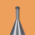


279
280
281
282
283
284
285
286

287
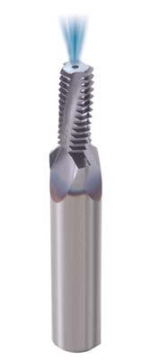
288
289 1/3 P Start Drill & Chamfer Backing Off Entrance Arc Thread Milling Exit Arc Retraction For Thread Milling
290
291
292
293 30 o 30 o 90 o 1o 47
294
295
296
297 5/P 0 Rmax P Rmin P
298 1/4P 0 1/8P
299
300 eft Hand Tool
301 eft Hand Tool
302
303
304
305
306


307
308
309
310


311 GROOVE MIING inserts toolholders technical data
312 GROOVE MIING INSERTS VARDE Ordering Code Circlip Non Standard Circlip DIN 471/47 O Ring DIN 3770 O Ring BS 180, DIN 301, DIN 3771 O Ring BS 4518 Groove Milling Holders Groove Milling Technical Data Page P-1 Page P- Page P-3 Page P-3 Page P-4 Page P-4 Page P-5 Page P-7 Vardex Ordering Code System Groove Milling Inserts 4 1 W GM C - 5 D3770 S VK Insert Size - Insert Style 3 - System 4 - Groove Std. Width 4-1/ W - Vertical Wide Inserts GM - Groove Milling Profile Shape - Groove Standard 7 - Groove Type 8 - Groove Depth C - With Chamfer CIRC - Circlip DIN471/47 DIN3770D DIN3770S BS180 BS4518 D - Dynamic S - Static DP- Dynamic pneumatic DH- Dynamic hydraulic Carbide Grade VK Groove Milling Shell Mill SGM 1 - D System - Cutting Dia. 3 - Drive Hole Dia. 4 - Insert Size SGM - Shell Groove Milling 48, 3, 80, 5, 7 4-1/ Groove Milling P-1
313 Circlip Non Standard External / View A t1 α W I.C. R Enlarged view A Vertical SGM Vertical SGM Insert Size Ordering Code Dimensions mm α mm W R t1 Toolholder 4WGM1.5C-CIRC WGM1.35C-CIRC WGM1.45C-CIRC WGM1.50C-CIRC WGM1.5C-CIRC WGM1.75C-CIRC WGM1.85C-CIRC WGM.00C-CIRC WGM.0C-CIRC / 4WGM.30C-CIRC WGM.50C-CIRC º SGM-D WGM.5C-CIRC WGM.70C-CIRC WGM.80C-CIRC WGM3.00C-CIRC WGM3.0C-CIRC WGM3.30C-CIRC WGM3.50C-CIRC WGM3.70C-CIRC WGM3.90C-CIRC WGM4.00C-CIRC P- Groove Milling
314 Circlip DIN 471/47 External / View A t1 α W m m I.C. Vertical SGM Enlarged view A Vertical SGM Insert Size Ordering Code Groove Std. α mm *m(h13) W t1 Toolholder 4WGM1.1C-D471/ WGM1.1C-D471/ WGM1.3C-D471/ WGM1.3C-D471/ WGM1.C-D471/ WGM1.C-D471/ / 4WGM1.C-D471/ WGM1.85C-D471/ º SGM-D WGM1.85C-D471/ WGM.15C-D471/ WGM.5C-D471/ WGM.5C-D471/ WGM3.15C-D471/ O Ring DIN 3770 External / View A t1 α W m m I.C. R1 R Enlarged view A Vertical SGM Vertical SGM Insert Size Ordering Code Groove Std. α mm St.Dy *m(h13) W t R1 R Toolholder 4WGM1.C-D3770S / St. 4WGM.0C-D3770S WGM.5C-D3770S WGM3.15C-D3770S º SGM-D Groove Milling P-3 St. = Static 4WGM1.C-D3770D Dy. 4WGM.0C-D3770D Dy. = Dynamic
315 O Ring BS 180, DIN301, DIN 3771 External / View A t α W I.C. R1 R Enlarged view A m m Vertical SGM Vertical SGM Insert Size Ordering Code Groove Std. α mm St.Dy *m(h13) W t R1 R Toolholder 1/ St. Dy. 4WGM1.80C-BS180S WGM.5C-BS180S WGM1.80C-BS180D WGM.5C-BS180D º SGM-D St. = Static Dy. = Dynamic BS 4518 External / View A t α W I.C. R1 R Enlarged view A m m Vertical SGM Vertical SGM Insert Size Ordering Code Groove Std. α mm St.Dy *m(h13) W t R1 R Toolholder 4WGM1.C-BS4518S St. 4WGM.4C-BS4518S WGM3.0C-BS4518S / DyP 4WGM.4C-BS4518DP WGM3.0C-BS4518DP º SGM-D DyH 4WGM.4C-BS4518DH WGM3.0C-BS4518DH St. = Static DyP = Dynamic pneumatic DyH = Dynamic hydraulic P-4 Groove Milling

316 Toolholders D t max. 1 d D1 Multi Insert Holders (3) Spare Parts Insert Size Ordering Code Dimensions mm D t max 1 d D1 Insert Screw Torx Key 1/ SGM-D SN4T-90 HK4T Toolholders D t max. H D1 d(h7) Multi Insert Holders (5) Spare Parts Insert Size 1/ Ordering Code SGM-D3--4 Dimensions mm D t max d(h7) D1 H Insert Screw Torx Key Holder Screw SN4T-90 HK4T M10x1.5x35 Groove Milling P-5
 D1 H Insert Screw Torx Key Holder Screw 80 3.5 7 7 50 SN4T-90 HK4T M1x1.")
317 Toolholders D t max H D1 d(h7) Multi Insert Holders (8) Spare Parts Insert Size 1/ Ordering Code SGM-D Dimensions mm D t max d(h7) D1 H Insert Screw Torx Key Holder Screw SN4T-90 HK4T M1x1.75x40 P- Groove Milling
CMT Vertical Mill-Thread
 CMT Vertical Mill-Thread Carmex presents a new family of vertical thread milling indexable inserts and toolholders to perform a wide variety of threads. Advantages of CMT - Vertical Mill-Thread Ground
Mill - Thread Inserts and Kits
 Mill - Thread s and Kits Mill-Thread tools for threading on CNC milling machines by using helical interpolation programs Advantages of Mill-Thread Tools Same toolholder and insert can produce both right-hand
Threading. Stellram offers high performance grades suitable for all machining applications, in a wide range of materials, for maximum productivity.
 Threading Stellram s comprehensive threading program is available in a wide range of thread forms. artial and full pro le inserts are offered for thread turning. Stellram offers high performance grades
For Extra Large Pitches METRIC
 or Extra arge Pitches METRIC or Extra arge Pitches Up to 25mm or 1 tpi Unique Design for Heavy Duty Applications VKX Vargus Tough Submicron Grade Inserts Anti-Rotation Stopper Toolholder Support Suited
E R H 10 (N) - 11 (C) 1
 - 11 (C) 1") Code System Holder Code System E R H 10 (N) - 11 (C) 1 2 3 4 5 6 7 Holder Type Hand Of Insert Name Height Of Shank Shim Insert Size Clamping System 1 Holder Type E R H 10 (N) - 11 (C) 4 Height Of Shank
Code System Holder Code System E R H 10 (N) - 11 (C) 1 2 3 4 5 6 7 Holder Type Hand Of Insert Name Height Of Shank Shim Insert Size Clamping System 1 Holder Type E R H 10 (N) - 11 (C) 4 Height Of Shank
MINI CATALOGUE inserts tool holders spares
 MINI CATALOGUE inserts tool holders spares T O O L I N G F O R O I L & G A S A U T O M O T I V E A E R O S PA C E G E N E R A L E N G I N E E R I N G Established in Washington on the North East coast of
THREADING. Korloy threading tools are available for machining various shapes of thread at various pitches while ensuring high quality performances
 THREAING Korloy threading tools are available for machining various shapes of thread at various pitches while ensuring high quality performances 1 Code System 02 Holder Code System 02 Insert Code System
D24. American ACME D02 D25 D26 D28 D28. UNJ (Unified Constant Thread) American Buttress (ABUT) British Buttress (BBUT) D09 D29 D30 D30 D30
 American Buttress (ABUT) British Buttress (BBUT) D09 D29 D30 D30 D30") 3 Code System 02 Holder Code System Thread Inserts 24 American ACME 02 Insert Code System 25 Stub ACME 03 Technical Information for 26 28 28 UNJ (Unified Constant Thread) American Buttress (ABUT) British
3 Code System 02 Holder Code System Thread Inserts 24 American ACME 02 Insert Code System 25 Stub ACME 03 Technical Information for 26 28 28 UNJ (Unified Constant Thread) American Buttress (ABUT) British
Scandinavian Tool Systems AB is a Swedish based manufacturer and supplier of tools for thread turning, thread milling, parting off and grooving.
 Edition 2015-10 Scandinavian Tool Systems AB is a Swedish based manufacturer and supplier of tools for thread turning, thread milling, parting off and grooving. The main product is the QuadCut, which on
Solid Carbide Thread Milling
 Solid Carbide Thread Milling 07 - '06 Contents Page GRADES OF COMBIDEX SOLID CARBIDE THREAD MILLS Micrograin 4 Order Example 4 ISO - Metric Thread 6O 5 ISO - Metric Fine Pitch Thread 6O 5 ISO - Metric
QuadThread. Internal. For Thread Turning
 QuadThread Internal For Thread Turning Scandinavian Tool Systems Scandinavian Tools System AB Our business idea is to offer the best rigid threading system to our customer and be in the front line of cutting
Solid Carbide Thread Milling
 Ordering Code Standard Fine D D L L T Height Pitch/mm Solid Carbide Thread Milling Contents Information Page - ISO Metric & External Thread Page - 2 ISO Metric Pitch & Fine Pinch External Thread 60º Page
NOTES FOR PLUG 30% RINGS UPTO 24MM 40% RINGS ABOVE 24 MM 40% 8) FOR LEFT HAND GAUGES ADD TO BASIC LIST PRICE.
 FOR LEFT HAND GAUGES ADD TO BASIC LIST PRICE.") NOTES 1) THIS PRICE LIST IS RIGHT HAND GAUGES ONLY. 2) PRICE INDICATED FOR PLUG ARE FOR A DOUBLE END CONSISTING OF GO & NOGO 3) PRICE INDICATED FOR RINGS ARE OF GO OR NOGO 4) PRICE FOR SINGLE ENDED GO
NOTES 1) THIS PRICE LIST IS RIGHT HAND GAUGES ONLY. 2) PRICE INDICATED FOR PLUG ARE FOR A DOUBLE END CONSISTING OF GO & NOGO 3) PRICE INDICATED FOR RINGS ARE OF GO OR NOGO 4) PRICE FOR SINGLE ENDED GO
List Ideal for Steels, Exotics and Difficult to Machine Materials. Type 5 (Lc=1 Thread) Type 6 (Lc=3 Threads) Miniature, Helical Flute
 Type 6 (Lc=3 Threads) Miniature, Helical Flute") List 41200 Miniature, Helical Flute P450 Size Threads Cutter Dia. Overall Neck Shank Dia. No. of Per Inch D L Lc L1 d 0 80 0.045 1.625 0.013 0.165 1/8 3 5 4120000115 1 72 0.055 1.625 0.016 0.198 1/8 3
List 41200 Miniature, Helical Flute P450 Size Threads Cutter Dia. Overall Neck Shank Dia. No. of Per Inch D L Lc L1 d 0 80 0.045 1.625 0.013 0.165 1/8 3 5 4120000115 1 72 0.055 1.625 0.016 0.198 1/8 3
ThreadMill. For Thread Milling
 ThreadMill For Thread Milling Scandinavian Tool Systems Scandinavian Tool Systems AB Our business idea is to offer the best rigid threading system to our customer and to be in the front line of cutting
Scandinavian Tool Systems AB is a Swedish based manufacturer and supplier of tools for thread turning, thread milling, parting off and grooving.
 Edition 2017-08 Scandinavian Tool Systems AB is a Swedish based manufacturer and supplier of tools for thread turning, thread milling, parting off and grooving. The main product is the QuadCut, which on
SPIRAL POINT TAPS for through hole tapping
 SPIRAL FLUTE TAPS for blind hole tapping Ideally suitable for blind hole tapping in most materials, particularly aluminium, brass, copper and similar metals. The build up of swarf at the bottom of the
Scandinavian Tool Systems AB is a Swedish based manufacturer and supplier of tools for thread turning, thread milling, parting off and grooving.
 Edition 2017-03 Scandinavian Tool Systems AB is a Swedish based manufacturer and supplier of tools for thread turning, thread milling, parting off and grooving. Our products are sold through distributors
QuadCut. External. For Thread Turning
 QuadCut External For Thread Turning Scandinavian Tool Systems Scandinavian Tool Systems AB Our business idea is to offer the best rigid threading system to our customer and to be in the front line of cutting
UNIVERSAL GAUGES. Norminal pitch Double Go or Normina pitch Double Go or Diametr Ended No Go Diametr Ended No Go Go.& 6 g. Go.& 6 g.
 ISO METRIC THREAD GAUGES 1/1/2013 STANDARDS : BASIC DIMENSIONS :- IS 4218 Part III & IV 1976 : ISO -724-1976 (E) Gauging Practice :- IS - 2334-1975 : ISO -1502-1978 (E) CLASS OF FIT : Screw Plugs :6H(Medium.)
Bluechip Tooling td Tel Table of Content Type Page range Metric M with chamfer M3 - M20 M5 - M Metric
 Bluechip Tooling td info@bluechiptooling.co.uk Tel 024 7647 4819 Circular Milling Cutters in Solid Carbide Version -Coating Uncoated Types Best Prices Best Endurance from Ø 4 Short processing times by
(Click on the links below for the category contents) YONG. Custom Hex Plain Plug Gages.. Page 29. Custom Cylindrical Plain Ring Gages...
 YONG. Custom Hex Plain Plug Gages.. Page 29. Custom Cylindrical Plain Ring Gages...") VER: YG1404 Thread Plug Gages - Inch - Taperlock Style Page 2-3 Thread Plug Gages - Inch - Reversible Style. Page 4 Thread Ring Gages - Inch... Page 5-6 Thread Plug Gages - Metric - Reversible Style...
VER: YG1404 Thread Plug Gages - Inch - Taperlock Style Page 2-3 Thread Plug Gages - Inch - Reversible Style. Page 4 Thread Ring Gages - Inch... Page 5-6 Thread Plug Gages - Metric - Reversible Style...
220º Ball Nosed Lollipop Cutter
 220º Ball Nosed Lollipop Series 722 Ultra-High Performance Solid Carbide -TiALN 30º Right Hand Helix - Micro-grain K30 4-Flute 220º Ball Nosed Tolerances: +0.00/-0.051mm h6 FL Neck Reach Dia- Dia- Dia
Thread Milling AM-CAT-THREADMILL(GB)-07/08. Cutters, Inserts and Holders
-07/08. Cutters, Inserts and Holders") Thread Milling AM-CAT-THREAMILL(GB)-07/08 Cutters, Inserts and Holders Allied Maxcut Thread Mills FEATURES - Complete programme available of both solid carbide and indexable insert thread mills - Full
Thread Milling AM-CAT-THREAMILL(GB)-07/08 Cutters, Inserts and Holders Allied Maxcut Thread Mills FEATURES - Complete programme available of both solid carbide and indexable insert thread mills - Full
Aluminium and (-2)* aluminium casting alloys *() * emulsion (long-chip) **
* aluminium casting alloys *() * emulsion (long-chip) **") System components for installation Standard range of HELICOIL plus manual and machine taps Range of types Recommended guide values Manual Machine tap tap Through hole Blind hole Cutting Cooling All hole
System components for installation Standard range of HELICOIL plus manual and machine taps Range of types Recommended guide values Manual Machine tap tap Through hole Blind hole Cutting Cooling All hole
Accuracy Build Credibility
 Geeta Engineering Works Accuracy Build Credibility Home Geeta Engineering Work is leading manufacturing Co. in India, Providing measuring instrument across the global. We are providing instrument of MESURING
Edge Preparation. Edge Preparation. Centre Drills...5. Spot Drills (90 & 120 ) Flute Countersinks...8. Edge Preparation
 Flute Countersinks...8. Edge Preparation") Centre rills...5 Spot rills (90 & 120 )...6 3 Flute Countersinks...8 Carbide Chamfer Countersink...8 Hole Countersinks...9 Carbide rill Mill...9 Single Flute Countersinks...10 Corner Rounding Cutters...11
Centre rills...5 Spot rills (90 & 120 )...6 3 Flute Countersinks...8 Carbide Chamfer Countersink...8 Hole Countersinks...9 Carbide rill Mill...9 Single Flute Countersinks...10 Corner Rounding Cutters...11
Product Catalogue 835. Smart Solutions on the Cutting Edge
 Product Catalogue 835 Smart Solutions on the Cutting Edge 1 2 The World of WhizCut Smart Solutions on the Cutting Edge Demand on production for small parts around the world is continuously increasing.
ng Drilli ng eadi Thr Turni ng illi ders ol H Tool r la ders odu hol M Tool
 1 HSS drilling Drilling 2 Solid carbide drilling 3 Indexable insert drilling 4 Reaming and Countersinking 5 HSS taps and dies Threading 6 Circular and Thread Milling 8 Turning Tools Turning 9 EcoCut 10
New Mini Tools Inch 2016
 TM -treme thread cutting New Mini Tools Inch 2016 Mini Tools Vertical s and Toolholders for threading, chamfering, grooving and turning Carbide grade: BLU-Sub-micron grade with advanced PV triple layer
PLAIN RING THREAD RING TRUNCATED SET PLUG TAPERLOCK THREAD PLUG TAPERLOCK PLAIN PLUG TAPER PIPE PLUG REVERSIBLE PLAIN PLUG REVERSIBLE THREAD PLUG
 THREAD RING TRUNCATED SET PLUG TAPER PIPE PLUG REVERSIBLE THREAD PLUG REVERSIBLE TRILOCK THREAD PLUG PLAIN RING TAPERLOCK THREAD PLUG TAPERLOCK PLAIN PLUG REVERSIBLE PLAIN PLUG REVERSIBLE TRILOCK PLAIN
Product features. only RS. Application-specific features RS. Indication for the RS UNF. 400 C max. 200 C. Lifting points ready for bolting RS RM
 Lifting points ready for bolting > WLL in comparison to DIN 580/582 Clear marking of the minimum WLL Large thread and WLL range M, MF, UNC, UNF, 8UN, BSW, G 0.1 t 8 t Product features High-strength octagon
Tap and Drill Bit Selection Guide
 148 2012/2013 Power Tools & Accessories Catalog Tap and Drill Bit Selection Guide American Standard and Unified Form Threads Tap drill size is approximately 7% of threaded depth. Thread Nominal Size Standard
Thread and Connector Identification
 How to Use this Section This section is intended as an aid to identifying the most popular threads on hydraulic hose couplings and adaptors, and hydraulic equipment. BSP, Metric, American and Japanese
NIAGARA CUTTER THREAD MILLING THREAD MILLS
 NIAGARA CUTTR THRAD MILLING THRAD MILLS 1 THRAD MILLS NTM100UN - Inch 3 NTM120UN - Inch 4 NTM160UN - Inch 5 NTM200UN - Inch 6 NTM400MI - Metric 7 CUTTING DATA Inch & Metric 8-9 Technical Info 10-11 THRAD
MEET OUR TEAM. North American Tool Corporation 215 Elmwood Avenue, PO Box 116, South Beloit, IL CURTIS LANSBERY PRESIDENT & CEO
 MEET OUR TEAM CURTIS LANSBERY PRESIDENT & CEO BRIAN KOBISCHKA VICE PRESIDENT & CFO PHIL SAMUELS DIRECTOR OF SALES & MARKETING JEFF SHERMAN DIRECTOR OF MANUFACTURING JON ANDERSON JOY BALDWIN BARB BISHOP
CUP POINT M3 - M16 15
 INDEX TRIVALENT METRIC ZINC PLATED SOCKET SCREWS PAGE TECHNICAL INFORMATION 3 DIMENSIONAL INFORMATION 4-5 M3 - M8 6 M10 - M24 7 TECHNICAL INFORMATION 8-9 M3 - M10 10 M12 - M24 11 TECHNICAL INFORMATION
Applicable for steel, stainless steel and cast iron Suitable for dry cutting
 Best of 2009 E62-6/2009-GBP Valid to 21st DEC 2009 80 0 The new Black Panther - insert has arrived! Applicable for steel, stainless steel and cast iron Suitable for dry cutting The latest generation of
121 indexable. Butt WelDeD tools. Die heads & chasers. restorers. Page Page sheet & tube Drills. Drills. Page Page...
 group 010 Butt WelDeD tools group 016 Die heads & chasers group 017 thread restorers Page...........................18 Page...........................19 Page...........................19 group 019 sheet
LEADER CORPORATION CATALOG
 LEADER CORPORATION CATALOG Release: 2012 Contacts: Justin Arcari Mike Arcari 51644 Filomena Drive Shelby Township, MI 48315 p. 586.566.7114 f. 586.566.7115 www.leader-corp.com 51644 Filomena Drive Shelby
Threadmill Nomenclature TMR N L ISO C
 Threami Nomencature 1 2 3 4 5 6 7 8 TMR N 16 139 40 2.5 ISO C 1 - ine TMR - Heica Futes MR - Heica Futes TMS - Straight Futes 2 - Too Type 3 E - Externa Threa N - Interna Threa X - Externa an Interna 3
Series Features: Diameters:.312,.375,.500,.625,.750, 1.000, 1.250, 1.500
 New design indexable threadmilling inserts and tool holders allow for a profitable and effective way to produce external and internal applications quickly while generating superior surface finish. Diameters:.312,.375,.500,.625,.750,
10,000 Series. Highlights C-6
 Highlights Features higher flows Benefits demanding mobile and industrial applications from Applications Description This is the biggest disc valve motor of our line with up to 45 GPM and 24,000 in-lb
OMT Technical Information Shaft Version
 A: Cylindrical 40 shaft C: Parallel key A12 8 70 DIN 6885 Keyway deviates from standard B: Cylindrical 1.5 in shaft D: Parallel key 3 /8 3 /8 2 1 /4 in B.S. 46 Keyway deviates from standard 45 C. Involute
-treme thread cutting. New. Swiss-Line. Inch
 New TM -treme thread cutting Swiss-ine Inch 2015-2016 Swiss-ine Swiss-ine Swiss style lathes are becoming a popular alternative to large lathes and machining centers in many companies. Carmex is introducing
Multimar. Universal Gage 844 T for external and internal dimensions
 - 10-4 Multimar. Universal Gage 844 T for external and internal dimensions The Universal Gage Multimar 844 T. Easy to use and versatile; ideal for all your measuring requirements in dimensional metrology.
Threadmill Nomenclature TR N L ISO C
 Threami Nomencature 1 2 3 4 5 6 7 8 TR N 16 139 40 2.5 ISO C 1 - ine TR - Heica Futes TS - Straight Futes 2 - Too Type 3 E N - Externa Threa - Interna Threa 3 - Too Shank ia. 04-4.0 mm 06-6.0 mm 08-8.0
HCG - HORN Catalog Guide
 CG - ORN Catalog Guide INTERNAL GROOVING Product line ore Ø 217 S274 S223 S224 231 S229/229 S312/312 315 S316.625 (15.87 mm).709 ( 18 mm).787-1.102 (20-28 mm) 1.102-1.496 (28-38 mm) > 1.496 (38 mm) Operation
HCG - HORN Catalog Guide
 Product line Bore Ø 217 264 S274 S223 S224 S229/229 S312/312 315 S316.625 (15.87 mm).709 ( 18 mm).787-1.102 (20-28 mm) 1.102-1.496 (28-38 mm) > 1.496 (38 mm) Operation Type HCG - HORN Catalog Guide INTERNAL
SOCKET HEAD CAP SCREWS METRIC SERIES M3-M36 RECOMMENDED RETAIL PRICES IN RUPEES PER 100 PIECES INCLUSIVE OF EXCISE DUTY & OCTROI
 Dia. M3 2.5mm SOCKET HEAD CAP SCREWS METRIC SERIES M3-M36 M4 3mm M5 4mm M6 5mm M8 6mm 5 1430 1250 6 1230 1250 1400 1430 8 910 940 960 985 1210 10 755 740 535 620 1100 12 755 670 540 655 840 1260 16 790
Introduction. Sparkplug / Plugsaver Kits
 RECOIL 2013 Introduction Standard Kits Standard Kits Sparkplug / Plugsaver Kits Replacement Insert Packets for Kits and Merchandiser Replacement Insert Packets for Kits and Merchandiser Range Kits Re-grip
Special Product Catalogue. T-A Drill Insert System
 Special Product Catalogue T-A Drill Insert System T-A Special Products - Application Example Automotive Cylinder Head Application - Cylinder Head Water Jacket Holes Application - Cylinder Head Water Jacket
Fine Pitch Cobalt Roughers
 ISO 01:08 Fine Pitch Cobalt Roughers Izar - HSCO 8% - M2 -Bright Finish DIN 8 NR-F - ISO 1-30º Helix - Fine Multi-Flute Square End Reg. Length-Roughers 13 7-17 8 19 9-23 22 72-29 2-1 2 - -8-1 38-1 -237
STAR TOOL SUPPLY / GRAND TOOL SUPPLY
 HOLE LOCATION PLUG GAGES SERIES 200: THREAD PLUG GAGES SERIES 635: All diameters concentric within.0001 T.I.R. Shaft dia. (C).2500 +.0002, -.0000 on all gages to simplify calculation of hole spread. Shaft
Super. Line. 10th Edition SUPER PRICE SUPER QUALITY SUPER AVAILABILITY
 Super Line SUPER PRICE SUPER QUALITY SUPER AVAILABILITY 10th Edition High-tech tools at a super price convincing price-performance-ratio exceptional quality immediate availability customer-friendly service
6000 Series Highlights
 Highlights Features 9 displacements available Presents a multitude of options that make this motor very smart and flexible to apply Benefits Very tough motor for demanding applications Can be used in a
Slow Speed Centers. For Conventional & Slow Speed Lathes. Revolving Center : Plain Point EXTRA HEAVY DUTY FOUR BEARING
 LIST EFFECTIVE FROM DATE : 01/07/2018 Slow Speed Centers TURNMAX MACHINE TOOLS - E-mail:sales@turnmax.in / turnmaxsales@gmail.com DATE : 01/07/2018 For Conventional & Slow Speed Lathes. Revolving Center
Thread Milling Tool GWF
 Thread Milling Tool GWF Thread milling >Ø20 mm Spiral flued solid carbide ools, some wih face cuer and fron chamfer This offers he following main advanages compared o he convenional mehods of apping and
35 & 35D. P.O. Box 1388 West Sacramento, CA (916) Fax: (916)
 Fax: (916)") 35 & 35D P.O. Box 1388 West Sacramento, CA 95691 (916) 372-5411 Fax: (916) 373-0952 www.hecogear.com Model 35 Installation Dimensions Model 35CF2-66-1 (Illustrated with Code 2 Flanged Output Shaft) 1.10
35 & 35D P.O. Box 1388 West Sacramento, CA 95691 (916) 372-5411 Fax: (916) 373-0952 www.hecogear.com Model 35 Installation Dimensions Model 35CF2-66-1 (Illustrated with Code 2 Flanged Output Shaft) 1.10
Disc Valve Hydraulic Motors Series 6000
 Disc Valve Hydraulic Motors Series 6000 10.2014 inspired hydraulics. Änderungen und Druckfehler vorbehalten 10.2014 EN EATON_Motoren english Highlights Features 9 displacements available Presents a multitude
BILZ TOOL CO., INC. CNC-2007 Rotating Toolholders & Accessories BELIN BILZ BOEHLERIT FETTE KIENINGER ONSRUD. Leitz Metalworking Technology Group
 BILZ TOOL CO., INC. CNC-2007 Rotating Toolholders & ccessories Leitz Metalworking Technology Group BELIN BILZ BOEHLERIT FETTE KIENINGER ONSRUD CNC Toolholders C O N T E N T S Introduction 3 CT40 CT40
Disc Valve Hydraulic Motors 4000 Compact Series
 Disc Valve Hydraulic Motors 10.2014 inspired hydraulics. Änderungen und Druckfehler vorbehalten 10.2014 EN EATON_Motoren english Port B Port A Features Shuttle Valve with Back- Pressure Relief Valve Highlights
BT Shank Tools BT30...E2 E18 BT40...E20 E60 BT50...E62 E95.
 BT Shank Tools BT30.................................................................................E2 E18 BT40................................................................................E20 E60 BT50................................................................................E62
HYDRAULIC MOTORS MLHH
 HYDRAULIC APPLICATION» Conveyors» Feeding mechanism of robots and manipulators» Metal working machines» Textile machines» Machines for agriculture» Food industries» Mining machinery etc. CONTENTS Specification
Mini-V Precise Turning, Grooving, Threading & Face Grooving
 INERNAL MACHINING Mini-V Pecise uning, Gooving, heaing & ace Gooving MERIC Innovative Gooving & uning Solutions Mini-V Mini ools fo Small & Meium Boes he Mini-V line by Goovex offes impove solutions fo
6000 Series. Highlights C-5. Description With torque up to 15,000 in-lb and 40 gpm continuous, this motor is packed with power operates very smoothly.
 Highlights Features 9 displacements available Presents a multitude of options that make this motor very smart and flexible to apply Benefits Very tough motor for demanding applications Can be used in a
Disc Valve Hydraulic Motors Series 4000
 Disc Valve Hydraulic Motors Series 0 10.20 inspired hydraulics. Änderungen und Druckfehler vorbehalten 10.20 EN EATON_Motoren english Highlights Features 10 displacements, a variety of mounting flanges
Conversion Factors 1
 Engineering Data Index Sect Title 1 Conversion Factors 2 Fraction - Decimal - Metric 3 MM to Inch to MM Conversion 4 Drill Sizes fraction/metric/no 5 Cutting Speeds 6 Spanner Sizes 7 Wood Screws 8 Self
ENGINEERING DATA. High Torque, Low Speed Motors H, S, 2000, 6000, and 10,000 Series. w w w. F l u i D y n e F P. c o m
 ENGINEERING DATA High Torque, Low Speed Motors H, S, 2000, 6000, and 10,000 Series Interchangeable with: Charlynn White Ross Parker Danfoss w w w. INDEX Cross Reference Guide...2 Introduction...3 H-Series...4
TAPS & DIES S.T.I. TAPS - HIGH SPEED GROUND MACHINE SCREW SIZES FRACTIONAL SIZES
 S.T.I. TAPS - HIGH SPEED GROUND High quality tap S.T.I. taps are oversize to rethread damaged threads Available in plug and bottoming style only MACHINE SCREW SIZES Plug Bottom Nominal H # of Thread Overall
VG-Cut. Complete Range of Turning Solutions INCH METRIC. Innovative Grooving & Turning Solutions
 VG-Cut Complete Range of Turning Solutions INC METRIC Innovative Grooving & Turning Solutions VG-Cut Complete Range of Turning Solutions Deep Grooving, Threading, Parting Off, oring and Face Grooving VARGUS
VIS 40 Series Two-speed
 Specifications Back Pressure Relief Shuttle Selector Plate Plate Balance Plate Face Seal Mounting Flange End Cap Front Retainer Seal Guard Output Shaft Selector Geroler Drive Bearings Shaft Seal VIS 40
GROOVING INSERTS. Thread Turning Index. Back to Main Index
 Grooving > Insers GOOVING INSETS Thread Turning Index Back o Main Index VADEX Ordering Code Sysem...Page 149 Exernal - DIN 471 eaining ing Grooves for Shafs...Page 150 Inernal - DIN 472 eaining ing Grooves
P.O. Box 1388 West Sacramento, CA (916) Fax: (916)
 Fax: (916)") P.O. Box 1388 West Sacramento, CA 95691 (916) 372-5411 Fax: (916) 373-0952 www.hecogear.com Model 16 Installation Dimensions 30,000 in lbs Continuous Torque Output 5.2 to 1 Ratio 20,000 lb. Maximum Radial
P.O. Box 1388 West Sacramento, CA 95691 (916) 372-5411 Fax: (916) 373-0952 www.hecogear.com Model 16 Installation Dimensions 30,000 in lbs Continuous Torque Output 5.2 to 1 Ratio 20,000 lb. Maximum Radial
TOTEM HSS HAND / SHORT MACHINE / LONG SHANK MACHINE TAPS
 PRICE LIST EFFECTIVE 04.02.2018 TOTEM HSS HAND / SHORT MACHINE / Forbes & Company Limited TOTEM HSS HIGH PERFORMANCE TAPS (AS PER IS - 6175 / 1977 BS 949 / 1976) SPIREX XL Bright Gold Xl Gold Size In MM
VIS (Valve-In-Star) Hydraulic Motor
 Hydraulic Motor") VIS (Valve-In-Star) Hydraulic Motor VIS 30 Series VIS 40 Series VIS 45 Series The next step in the evolution of low speed high torque (LSHT) hydraulic motors. EATON Low Speed High Torque Motors E-MOLO-MC001-E5
VIS (Valve-In-Star) Hydraulic Motor VIS 30 Series VIS 40 Series VIS 45 Series The next step in the evolution of low speed high torque (LSHT) hydraulic motors. EATON Low Speed High Torque Motors E-MOLO-MC001-E5
Small Tool Instruments and Data Management
 Small Tool Instruments and Data Management Digital Micrometers Pages 28 34 Analogue Micrometers Pages 35 42 Special Version Micrometers Pages 43 63 External screw type micrometers accessories Pages 65
Roller chain idler sprocket units Idler pulley units
 Roller chain idler sprocket units Idler pulley units Roller chain idler sprocket units, idler pulley units Page Product overview Roller chain idler sprocket units, idler pulley units... 334 Design and
Disc Valve Hydraulic Motors 2000 Series
 Disc Valve Hydraulic Motors 10.2014 inspired hydraulics. Änderungen und Druckfehler vorbehalten 10.2014 EN EATON_Motoren english Highlights Port A Features Three zone design for longer life and true bi-directionality.
Grooving & Threading. Featuring the. Kit Sale. SIGE Internal Grooving System. KTGF External Grooving System for Swiss Machines. KTNR Threading System
 Grooving & hreading Kit Sale eaturing the SIGE Internal Grooving System KG External Grooving System for Swiss Machines KNR hreading System Bonus Offer! Buy 10 Cera-Notch Grooving Inserts in New MEGCO Grade
POWER PRICE UNI. powerful UNF METAL. UNCPower. power ful GOLD FOR. powerful TOP GEOMETRIES UNF PERFECT CHOICE VER. perfect thread form.
 MADE BY UNIVERSALtaps TOP GEOMETRIES FORM EUNIVERSAL UNIVERSAL TAPS powerful perfect UNF longideal flutes choice tool life PROCESS RELIABLE PERFECT universal power ful UNC-THREAD ISO-METRIC THREADS GUHRING
2017 NORTH AMERICA TAPS EDITION
 2017 NORTH AMERICA TAPS EDITION PRIMED FOR PRODUCTIVITY THE MOST POWERFUL TAPS IN THE BUSINESS PROUDLY BEAR OUR NAME. WIDIA-GTD delivers a complete range of solid carbide, high performance, multipurpose,
Applicable for steel, stainless steel and cast iron Suitable for dry cutting
 Best of 2008/1 E62-6/2009-GBE Valid to 30.09.2009 The new Black Panther - insert has arrived! Applicable for steel, stainless steel and cast iron Suitable for dry cutting The latest generation of face
The Ultimate Solid Carbide Indexable Drill with a
 The Ultimate Solid Carbide Indexable Drill with a Chamfering Option! Replaces Any Cylindrical Solid Carbide or High Speed Steel Drill www.iscar.com Engineered for Chamfering Performance Modular System:
Table of Contents. Standard Taps
 Table of Contents Standard Taps Standard Taps--High Speed Steel Machine Screw Sizes... 3 Standard Taps--High Speed Steel Hand Taps (Fractional Sizes)... 5 Standard Taps--High Speed Steel Machine Screw
Tooling for Swiss Automatics
 Tooling for Swiss Automatics MANUFACTURED IN SWITZERLAND Swiss Precision Tools I S O 9 0 0 1 CERTIFIED SWISS PRECISION SWISS QUALITY Providing tolerances unmatched in the industry TIR (in) REGO-FIX Cylindrical
SAMPLES GAUGES. Tolerances OUR SPECIAL OFFER: PLUG GAUGES WITH REQUIRED FIT OR INDIVIDUAL TOLERANCES ACCORDING TO YOUR SPECIFICATIONS
 SAMPLES GAUGES PLUG GAUGES Tolerances GO side Fit NO GO side OUR SPECIAL OFFER: PLUG GAUGES WITH REQUIRED FIT OR INDIVIDUAL TOLERANCES ACCORDING TO YOUR SPECIFICATIONS BESTSELLER: FEELER GAUGE TAPES IN
CALL US WITH YOUR MACHINE MAKE & MODEL. WHETHER YOU NEED COOLANT THRU OR SOLID, WE WILL FIND THE RETENTION KNOB FOR YOU!
 RETENTION KNOBS For CAT40, CAT50, BT0, BT40 & BT50 CAT40 Retention Knobs 5/8 Description DWG. T A L HOLE? Socket X70A 40EA / A45.440(C.8) A A.65 45.5 Y RKW40 X70A 40EA / A45.440 A A.65 45.5 N RKW40 X704A
FIXED DISPLACEMENT VANE PUMPS
 FIXED DISPLACEMENT VANE PUMPS Single Vane Pumps Double Vane Pumps Thru-Drive Vane Pumps HS - HQ - VH - SERIES Working pressure: up to 210 bar Displacements: from 3 cc to 200 cc Pumps, cartridges and spare
GROUPCODE NEN : ANSI : STEEL BS : STEEL
 RETAINING RINGS FOR BORES - NORMAL TYPE - ➁ DIN : 4 8 8 9 10 11 1 13 14 15 s 0,8 0,8 1 1 1 1 1 1 ring d3 8, 9,8 10,8 11,8 13 14,1 15,1 16, d4 3 3, 3,3 4,1 4,9 5,4 6,, d 8,4 9,4 10,4 11,4 1,5 13,6 14,6
TC SERIES THREADMILLING. Threadmilling Insert Nomenclature Chart TI 15 N 8 UN. type of insert. Neutral Positive. insert length
 C SERIES HREADMIING hreadmilling Insert Nomenclature Chart I 15 N 8 UN I threadmilling insert insert length type of insert N P 75.750 (19.05) 1 1.000 (25.40) 1.5 1.500 (38.10) hreadmilling Cutter Nomenclature
Lubrication Fittings. 1/4"-28 Taper Thread Fittings
 1/4"-28 Taper Thread Fittings Used on most cars and trucks and many industrial machines. It is recommended that SAE-LT taper threads be assembled into 1/4"-28 UNF, Class 3B, straight threaded holes having
Engineering Data. Assembly Length. How to Determine Correct Assembly Length
 Assembly Length How to Determine Correct Assembly Length For most assemblies, the correct assembly length may be determined by direct measurement of the equipment or a drawing. Minimum bend radii as shown
HTR Precisions Cutting Tools is proud to offer you the complete range of cutting tools of superior quality according to international standards.
 2015 2016 Introduction HTR Precision Cutting Tools is a wholly owned black empowered company incorporated for the purpose of manufacturing and supplying precision cutting tools, in response to the growing
How to Identify Fluid Ports and Connectors
 How to Identify Fluid Ports and Connectors Accurate identification of ports and connectors in fluid piping systems is necessary before the correct hose or tube assembly can be selected and installed. With
US version. Drain connection
 Versions OMT Versions Mounting flange Standard flange Shaft Port size Europea n version US version Drain connection Check valve Low pressure release High pressure release Cyl. 4 mm G 3/4 X Yes Yes OMT
CERATIZIT designation system
 C5 CEATIZIT designation system Tool holders UTS / HSK-T system Assembly size (system) MSS system E = external / I = internal Assembly size Hand Approach angle Parting and grooving depth Shank section,
Index SECTION L PLASTICS
 Index SECTION L PLASTICS PRODUCT PAGE SECTION I NON-METALLIC SPROCKETS.... L-2 L-30 SPROCKETS - STOCK NO. 25 ¼" PITCH...L-5 NO. 35 3 8" PITCH...L-6 NO. 40 ½" PITCH...L-7 NO. 50 5 8" PITCH...L-8 NO. 60
Industrial Tooling Corporation Ltd. Product Catalogue Issue 10
 Industrial Tooling Corporation Ltd. Product Catalogue Issue 10 Company Profile Company Profile ITC is a round tool specialist. Our objective is simply to provide you, our customer, with the correct cutting