Build your own THUNDERBIRD 2
|
|
|
- Leslie Singleton
- 5 years ago
- Views:
Transcription


1 PACK 04

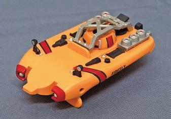
2 PAGE 19 Pod 3 base Pod 3 details and Firefly Pod 3 laboratory and Firefly Pod 3 floor details and Firefly Pod 3 inspection walkways Pod 3 right inner wall Pod 3 right inner wall and Excavator 84 Editorial and design by Continuo Creative, North Road, London N7 9DP. Published. in the UK by De Agostini UK Ltd, Battersea Studios 2, 82 Silverthorne Road, London SW8 3HE. Published in the USA by De Agostini Publishing USA, Inc., 121 E. Calhoun Street, Woodstock, IL All rights reserved 2017 Warning: Not suitable for children under the age of 14. This product is not a toy and is not designed or intended for use in play. Items may vary from those shown.


3 19 POD 3 BASE YOUR PARTS Tools and materials: Screwdriver Front base panel Rear base panel Axles x 2 Rollers x 2 Roller ends x 4 Screws (2.6 x 5mm) x Join the front and rear base panels via these four lugs. Secure with four 2.6 x 5mm screws. Make sure all four screws are secure. 66


4 Fit a roller end into a roller. Make sure there are no gaps. Fit the other end, then repeat so you have two rollers with both ends fitted Fit an axle through the hole in the end of one of the rollers. Feed it through the other end. Arrange so there is an equal length of axle emerging from both ends. Repeat so both rollers are prepared. 10 Making sure the axle remains inside the roller, fit the axle s tips into the brackets either side of the hole in the base s front panel. 11 Make sure the roller is seated correctly. 12 Repeat for the other roller, seating 13 it at the rear of the pod base. Your assembly should look like this. 67


5 Carefully lower the pod assembly onto the base, like this. Make sure the rollers stay in position. Line up these holes. Check again that the rollers are still in position, and can rotate freely Turn a screw into this central hole... Then this hole... Now these two COMPLETE Use six more screws to finish tightening the floor to the base, via these holes. Roll the pod back and forth a bit to check again that the rollers work, then this stage is complete. BRAINS TOP TIPS If you want to apply some weathering effects to the interior of Pod 3, it is a good time to do this now. See the info in Stage 08 for more on this. 68


6 20 POD 3 DETAILS YOUR PARTS + FIREFLY Tools and materials: Superglue, tweezers Plug Detail 1 Details 2 x 2 Detail 3 Detail Fit the plug to cover this screw hole. 02 Then glue detail 1 here, via these pins. All details fitted in this stage should be secured with a dot of superglue at their contact point. 03 Fit a detail 2 here and the other next to it. 69


7 05 06 COMPLETE Fit detail 3 like this. Detail 4 fits here, with its tab holding it in position via this groove. FIREFLY Tools and materials: Side cutters, superglue Chassis Tracks x 2 Drive wheels A x 2 Drive wheels B x 2 Axles x 4 Wheels A x 6 Wheels B x Remove drive wheels A and B from their sprues. Remove any burrs, then glue the parts A and B together via the circled tabs/slots. Press the parts together to secure them. 70 Your drive wheels should look like this.


8 Repeat for the wheels A and B. Press the parts together so the glue dries. You should have six wheel sets, like this Front 10 Back Fit one of the drive wheel sets onto the tip of one axle. Now fit the three other axles into three wheel sets. Fit the drive wheel axle through the rearmost hole in the chassis. Fit the other drive wheel set onto the opposite axle tip Press the parts together so they are flush with the chassis. Repeat Steps for a wheel and axle set. Use a free wheel set on the other tip again. Repeat so all the wheels are fitted, like this COMPLETE Pull one of the rubber tracks over the wheels, starting from the drive wheel. Make sure the track is seated neatly over the wheels. Repeat for the other tracks, then roll the model back and forth a bit to check both are fitted correctly. 71


9 21 POD 3 LABORATORY + FIREFLY YOUR PARTS Tools and materials: Tweezers, superglue Lab part 1 Lab part 2 Cylinder Plugs x 6 Lab part 3 Lab exterior Fit lab parts 1 and 2 like this (inset). The outlined pins are at the front of the parts. All the lab and detailing parts used in this stage should be glued in place. Glue the cylinder here. Fit lab part 3 onto the top of the lab exterior, via these four locating pins. Now fit lab parts 1 and 2 assembly here Cover this hole with a plug. Then cover these holes. Glue the lab assembly here, via the arrowed pins. 72


10 08 09 Make sure there are no gaps between the lab and the floor. FIREFLY The rear of the lab will sit against the circled section of frame like this. COMPLETE Tools and materials: Superglue Main body Under cover Lamp covers L + R Searchlights L + R Front fender Chemical tanks x 2 Body details: Aerial base 1 Rear fender Frame 1 Water tank Frame 2 Radiator fins Aerial bases 2 x 2 Nozzle Glue the aerial base 1 to the rear of the underside of the main body here. All detailing parts should be secured with a dot of superglue. Remove the radiator fins from their sprues, trim any burrs, then glue them next to the aerial base. The parts should look like this The rear fender will seal the parts in, like this. Glue the under cover to these holes. 73 Now glue the front fender to this.


11 Glue the left lamp cover here. And the right one here. The left searchlight goes here. Be careful, as the part is thin and delicate. And the right one goes here Body detail 2 goes here, behind the right searchlight. Detail 1 goes here. Aerial bases 2 go in the circled locations. Detail 3 goes here. Orient the part exactly as shown, inset Detail 4 goes here. Again use the inset to help orient the part correctly. 19 Your detailing parts should look like this. 20 The chemical tanks will fit here. Glue these parts in place via their pins. 21 The other set of tanks goes on the other side. 22 Up Body detail 5 goes here. Frame 1 goes here. The parts should look like this. Fit the nozzle into the water tank, using a little glue on the arrowed tab. Use the inset to orient the part COMPLETE It should look like this. Fit the water tank to the main body via these lugs. 74 Frame 2 will cover it, like this.


12 22 POD 3 FLOOR DETAILS YOUR PARTS Tools and materials: Superglue + FIREFLY Detail 5 Plug Detail 6 Detail 7 Detail 8 Details 9 x Detail 5 will fit into these holes. It doesn't matter which way round it goes. All details fitted in this stage should be secured with a small dot of superglue. Start by slotting the forward tip under this section on the front wall, then fit the detail s four pins. Glue detail 7 to these holes, across from detail 5. The inset shows its proper orientation. Similarly, glue detail 8 here, against the edge Detail 9 goes here, next to 7. Press detail 9 into place carefully, from its base rather than the top of the part. Glue the second detail 9 next to detail Detail 6 fits here, covering the screw hole.


")


13 09 10 COMPLETE Fit the plug over this screw. Make sure the pipe detail links up. FIREFLY Tools and materials: Superglue Cockpit Shield Actuators Actuator arm (left) Windscreen Horn Actuator arm (right) Aerials x Glue the windscreen to the cockpit like this. Press the part into place. The horn goes here. Orient the part like this The cockpit assembly slots onto the front of the main body like this. Here is how the upper body section of Firefly should look. Now lower the body/cockpit assembly onto the chassis base via these lugs like this. 76


14 09 Top 10 Top 広 広 Fit the right actuator arm to one of the actuators. Both actuators are the same, but make sure you orient the parts to one another correctly. Repeat for the left actuator arm and actuator Glue the right actuator arm pairing to these pins on the right side of the shield s reverse. The parts should join neatly, like this. Lay the shield face down like this Check the arm is perpendicular to the shield. Repeat Steps for the left arm. Leave the glue to dry Once the glue has dried fully, fit the shield to the main body via these holes in the sides. Be careful when widening the arms. Make sure the arms are parallel to each other, and in line with the main body. Do not glue. Move the shield up and down a few times to check its movement is unobstructed. Glue the first aerial here COMPLETE And the second one here. The third aerial goes here. That completes this stage. 77


15 23 POD 3 INSPECTION WALKWAYS YOUR PARTS Tools and materials: Superglue Walkway R1 Walkway C1 Stay L1 Stay R1 Walkway R2 Walkway L1 Stay L3 Stay R3 Walkway C2 Stay L5 Stay R5 Walkway L Look for the R marks on the walkways R1 and R2. Join these via the arrowed pins/holes. Use a little glue to bond them. Pinch the parts to secure them. The right walkway should look like this As in Step 01, look for the Ls on walkways L1 and L2. Join these with a little glue. Press these together. The left walkway should look like this. 78


16 09 10 Front Front Join walkways C1 and C2 with a little glue. Back This walkway crosses the pod interior, joining the right and left walkways. There are small pins at the ends of walkway C. Note the difference between these parts. Glue walkway C to the right walkway. Be very careful to orient the part exactly as shown here. The join should look like this. 13 Front Now glue walkway C to the left part. Make sure the walkways handrails are all joining each other neatly, as a continuous rail. The pod s interior walkways are complete Remove stay L1 from the sprue, removing any burrs. Stay L1 (which has a 1 marked on it) fits to the foremost frame, via its two pins. Use glue for all the stays to bond them to their frames. The stay should fit like this Now fit stay R1 to the opposite section of the frame. Stay L3 has a 3 marked on it: fit this to the third frame like this.


17 Now fit stay R3 opposite it. Stay L5 has a 5 marked on it: fit this to the fifth frame like this Fit stay R5 opposite it. Check the position and fit of all stays. Pinch each stay to ensure it is securely fitted and wait for the glue to cure Once the glue is dry, open the pod s hatches and feed the walkways through the front opening, like this. 30 Secure the walkways by gluing the recesses in their footpath sections to the tips of all six stays (circled). COMPLETE Hold the parts in place to be sure the glue dries, then this step is complete. 80


18 24 POD 3 RIGHT INNER WALL YOUR PARTS Tools and materials: Tweezers, superglue Detail 5 Right inner wall Detail 1 Detail 3 Details 2 x 2 Detail 6 Lights x 6 Detail 4 Identification plate Glue detail 1 to the inner wall here. Again, all details used in this stage should be secured with a dot of Detail 1 should fit like this. Glue the first detail 2 next to it. It doesn't matter which way up it goes Glue the other detail 2 here like this. Glue detail 3 here... 81


19 Top Bottom... like this. Familiarise yourself with detail 4, which Glue the part into this indent. slopes up and outward to match the contour of the inner wall It will match the inner wall s outward curve, like this. Details 5 and 6 have an R stamped on their reverses. Detail 5 goes in this recess Make sure the part is oriented like this. Detail 6 will sit next to detail like this Remove the lights carefully, and glue the first set here. Press the part into place. 82 The next light fits here.


20 The next one goes here. The front set of lights are now in place. Glue another light here and another here The last set of lights go here. The rear three are now in place. All six lights are in place Use tweezers to lower the identification plate through the second and third frames, facing inwards The two pins on the frames will locate the plate. COMPLETE Use a little glue to affix the plate. The plate should be angled slightly downwards, like this. (Inner wall temporarily fitted) 83


21 25 POD 3 RIGHT INNER WALL YOUR PARTS + EXCAVATOR Detail 7 Detail 8 Detail 11 Detail 14 Detail 17 Detail 20 Detail 22 Detail 12 Detail 18 Detail 23 Detail 9 Detail 10 Detail 13 Detail 15 Detail 16 Detail 19 Detail 21 Detail Bottom Use a little glue to affix detail 7 here. All the details fitted in this stage will be secured with superglue. Detail 9 goes here. Detail 10 goes here. Detail 19 fits here, oriented as shown in inset Detail 13 goes here. Detail 12 fits here. Detail 11 goes here. Detail 8 fits here. 84


")


22 Bottom Detail 15 goes here. Detail 16 fits here. Detail 18 goes here, oriented as shown in inset. Detail 14 goes here, like this. It will sit out from the wall on its posts Detail 17 goes here. Affix detail 20 onto 21, as shown in inset. Now fit the parts here, oriented as shown. Fit detail 22 here. Its step (circled) will fit at the bottom of the wall COMPLETE Detail 23 will go next to it, again with its step at the bottom of the assembly. Detail 24 goes here. Its step is again at the bottom. That completes this stage. (Inner wall temporarily fitted) EXCAVATOR Drive wheels A x 2 Drive wheels B x 2 Front grille Chassis Tracks x 2 Wheels A x 2 Wheels B x 2 Axles x 4 85


23 01 Separate the drive wheels A and B, and glue 02 them together as you have done previously. Now do the same for the wheels A and B Front Back Fit a drive wheel set onto one of the axles, like this. And fit wheel sets onto the other three. Check the orientation of the chassis Fit the front grille to the front end of the chassis. Make sure it is the right way up with the slope matching that of the chassis. Fit the drive wheel/axle through the rearmost holes in the chassis side Use the remaining drive wheel set to complete it. 12 Do the same for the wheels/axles. 13 Pinch the parts to secure them. COMPLETE The parts should look like this. Fit the tracks as you have done before. 86
Build your own THUNDERBIRD 2
 PACK 03 PAGE 12 Pod 3 front hatch and Elevator Car 2 43 13 Pod 3 rear hatch and Elevator Car 2 46 14 Pod 3 floor and Elevator Car 2 49 15 Pod 3 frames and FAB 1 52 16 Pod 3 frames and FAB 1 55 17 Pod 3
Build your own THUNDERBIRD 2
 PACK 06 PAGE 33 Telescopic legs C and I.R.3 112 34 Telescopic legs D and I.R.3 115 35 Leg bases and Thunderizer 118 36 Landing feet and Elevator Car 3 121 37 Leg rail-gear racks and Elevator Car 3 124
Build your own THUNDERBIRD 2
 PACK 11 PAGE 67 Pod 4 ramp tracks and Jet Air Transporter 224 68 Left rear booster and Alan s Racing Car 227 69 Right rear booster and Alan s Racing Car 230 70 Left booster speaker 233 71 Right rear booster
Build your own THUNDERBIRD 2
 PACK 12 STAGE PAGE 74 Tailwing ramjets and Cobra Half-track 247 75 Tailwing intakes 250 76 Tailwing fins 253 77 T2 control board 255 78 T2 wings and Mobile Crane 258 79 T2 side frames and Mobile Crane
Build your own THUNDERBIRD 2
 PACK 01 STAGE PAGE 01 Nose assembly and Elevator Car rear wheels 3 02 Cockpit interior and Elevator Car 1 completion 7 03 Missile launcher and Thunderbird 4 11 04 Nose assembly and the Tracy brothers 15
The front wheel and mirror
 Pack 01 1 The fuel tank 3 2 The front wheel and mirror 5 3 The headlight 6 Editorial and design by Continuo Creative, 39-41 North Road, London N7 9DP. Published in the UK by De Agostini UK Ltd, Battersea
Build the legendary PORSCHE RS 2.7. Pack 12
 Build the legendary PORSCHE RS 2.7 Pack 12 Build the legendary P O R S C H E RS 2.7 Contents PAGE STAGE 92 The rear shelf 368 93 The engine cover 372 94 The engine cover hinges 376 95 The rear panel 380
Build the. Steam Locomotive. Pack 01
 Build the Steam Locomotive Pack 01 Build the Steam Locomotive Contents Step by step Stage 01: The smokebox door Stage 02: The smokebox Stage 03: The first driving wheels and coupling rods Stage 04: The
Build your own. Pack. Stages 39-42: Receive more of Robi s electrical components
 Build your own Pack 11 Stages 39-42: Receive more of Robi s electrical components Build your own All rights reserved 2016 CONTENTS Published in the UK by De Agostini UK Ltd, Battersea Studios 2, 82 Silverthorne
Build the legendary PORSCHE RS 2.7. Pack 5
 Build the legendary PORSCHE RS 2.7 Pack 5 Build the legendary P O R S C H E RS 2.7 Contents PAGE STAGE 29 Rear disc brake 120 30 Rear wheel 123 31 Rear disc brake 126 32 Rear wheel 129 33 The crankcase
BUILD YOUR OWN. Pack 16
 BUILD YOUR OWN TM Pack 6 0 CONTENTS Assembly Guide 43 Stage 5: The left fuel tank base Stage 5: The engine cables Stage 53: The LED tester Editorial and design by Continuo Creative, 39-4 North Road, London
3D PRINTER. Pack 09. Anything you can imagine, you can make! 3D technology is now available for you at home! BUILD YOUR OWN
 BUILD YOUR OWN Pack 09 Anything you can imagine, you can make! 3D PRINTER Compatible with Windows 7 & 8 Mac OS X 3D technology is now available for you at home! www.model-space.com BUILD YOUR OWN 3D PRINTER
Build the legendary PORSCHE RS 2.7. Pack 3
 Build the legendary PORSCHE RS 2.7 Pack 3 Build the legendary P O R S C H E RS 2.7 Contents PAGE STAGE 13 The rear engine cover 55 14 The left intake manifolds and throttle bodies 59 15 The right intake
3D PRINTER. Pack 10. Anything you can imagine, you can make! 3D technology is now available for you at home! BUILD YOUR OWN
 BUILD YOUR OWN Pack 10 Anything you can imagine, you can make! 3D PRINTER Compatible with Windows 7 & 8 Mac OS X 3D technology is now available for you at home! BUILD YOUR OWN 3D PRINTER CONTENTS PACK
Instructions: Pullman-Standard PS-3 Coal Hopper Kit Tangent Part Numbers: through /2015
 Instructions: Pullman-Standard PS-3 Coal Hopper Kit Tangent Part Numbers: 15000-01 through 15001-01 10/2015 Thank you for purchasing the Tangent Scale Models Pullman-Standard PS-3 Coal Hopper Kit! A few
4mm scale 009 gauge Lodge Hill & Upnor railway Chattenden Drewry loco body kit.
 RT Models 4mm scale 009 gauge Lodge Hill & Upnor railway Chattenden Drewry loco body kit. HISTORY The loco was supplied by the Drewry car co. to the Lodge Hill & Upnor Railway in 1949, works number 2263.
Audi S4 SMIC Installation. B5 Audi S4 Side Mount Intercooler installation
 Audi S4 SMIC Installation B5 Audi S4 Side Mount Intercooler installation Disclaimer: These installation instructions are to be used as a guide only. It is at the reader and/or installer s discretion to
20964/B 20964/B 2014 TOYOTA TUNDRA TUNDRA. Billet Grille. Fig 1. Fig 2
 Billet Grille TOOLS REQUIRED: PARTS LIST: Socket Set (6) U-Nuts Flat/Phillips Screw Drivers (8) #10 Screws Pliers (2) #8 Screws ¾ (2) 2 Flange Bracket (1) Top Plate Overlay Bracket - driver (1) Top Plate
Prusa i3 Printer Assembly Guide
 Prusa i3 Printer Assembly Guide Special thanks to Carlos Sanchez and Miguel Sanchez for the graphics. All graphics captured from their great animation: http://www.carlos-sanchez.com/ Prusa3/ For copyright
FITTING KIT No s : BULL BAR WINCH ( P/No ) BULL BAR NON WINCH ( P/No )
 BULL BAR NON WINCH ( P/No )") ARB WINCH / NON WINCH BULL BAR TO SUIT LANDROVER DISCOVERY 2003 ONWARD. FITTING KIT No s :- 617 1793 BULL BAR WINCH ( P/No 343 2120 ) 617 1794 BULL BAR NON WINCH ( P/No 323 2120 ) WARNING FOR VEHICLES
ARB WINCH / NON WINCH BULL BAR TO SUIT LANDROVER DISCOVERY 2003 ONWARD. FITTING KIT No s :- 617 1793 BULL BAR WINCH ( P/No 343 2120 ) 617 1794 BULL BAR NON WINCH ( P/No 323 2120 ) WARNING FOR VEHICLES
<THESE INSTRUCTIONS MUST BE GIVEN TO THE END USER> B&W
 B&W Trailer Hitches 6 Hawaii Rd / PO Box 86 Humboldt, KS 66748 P:60.473664 F:60.869.903 Turnoverball Gooseneck Hitch Installation Instructions MODEL 08
Instructions: General American 6,000 Gallon, 3-Compartment Tank Car Kit 11/2013
 Instructions: General American 6,000 Gallon, 3-Compartment Tank Car Kit 11/2013 Thank you for purchasing the Tangent Scale Models General American 6,000 Gallon, 3- Compartment Tank Car Kit! A few quick
MARDER II ENGINE COMPARTMENT
 TWS 353048 MARDER II ENGINE COMPARTMENT Congratulations on purchasing one of the finer aftermarket resin conversion sets available. This kit was Mastered by Tom Kondziolka. This kit is intended to be used
WARNING. When installed in accordance with these instructions, the front protection bar does not affect operation of the SRS airbag.
 Part Number: 343870 F/Kit 17557 Product Deluxe Combination Winch and Non Winch Bull Bar Description: Suited to Nissan XTERRA 05ON USA Only vehicle/s: WARNING REGARDING VEHICLES EQUIPPED WITH SRS AIRBAG;
The H-MAC Heavy Metal Articulating Chassis Construction Guide
 The H-MAC Heavy Metal Articulating Chassis Construction Guide The Heavy Metal Chassis is constructed with two identical drive modules built using 10 mechanical sub-assemblies. The drive modules are integrated
LAND ROVER DISCOVERY 3 ARB BULL BAR AND WINCH BAR WARNING
 LAND ROVER DISCOVERY 3 ARB BULL BAR AND WINCH BAR PART No 3432150 DISCOVERY 3 WINCH BAR PART No 3232150 DISCOVERY 3 BULL BAR WARNING FOR VEHICLES EQUIPPED WITH SRS AIRBAG WHEN INSTALLED IN ACCORDANCE WITH
In area - A -, a proper seal must be made against the top of the window glass.
 Door window, adjusting Page 1 of 3 Audi > B3 > 1994-1998 Body Exterior, Interior 61 - Convertible top, checking and adjusting Door window, adjusting Sections C-C and D-D. Adjust door window so that window
Instructions: PRR Sam Rea Shops X58 Class Box Car Kit Tangent Part Numbers: XX through XX 9/2015
 Instructions: PRR Sam Rea Shops X58 Class Box Car Kit Tangent Part Numbers: 14000-XX through 14002-XX 9/2015 Thank you for purchasing the Tangent Scale Models PRR Sam Rea Shops X58 Class Box Car Kit! A
54531/ FORD FUSION
 54531/51531 54531/51531 13-15 FORD FUSION 13-15 FORD FUSION FORD FUSION Upper Class Grille w/ Bars TOOLS REQUIRED: Socket Set Flat/Phillips Screw Drivers Torx Bits Plastic Pry Bar 3/16 Drill Bit and Drill
COLD AIR INTAKE INSTALLATION INSTRUCTIONS
 COLD AIR INTAKE INSTALLATION INSTRUCTIONS # D760-0030 Fits: 2007-10 135i (E82, E88; with N54 engine) 2007-08 335i/xi (E90) 2007-10 335i (E92, E93; with N54 engine) Congratulations for being selective enough
Copyright 2009, John Jogerst. Not for commercial use. For personal or educational use only
 Space Falcon 9 (Heavy modification) 1:100 scale Where it is not obvious, red arrows mark the places to cut. Payload Fairing: Cut out the three parts for the upper fairing. Roll the smallest part into a
MR-1. Please read and understand all instructions before building!
 MR-1 This kit contains all the parts necessary* to build a flying high power rocket: (1) Pre-slotted main airframe (1) Nose cone with strap (3) Fins (1) Transition (1) Airframe section 1 long (1) Piston
Current Range Rover Sport STRUT Collection Installation Manual
 2014 - Current Range Rover Sport STRUT Collection Installation Manual 1 1. Removing Main Grille and Lower Fascia 1.1 Run a line of low tack masking tape across the front of the bumper below the grille
Installation instructions, accessories - Rear Seat Entertainment
 XC90 Section Group Weight(Kg/Pounds) Year Month 3 39 2004 10 XC90 2003, XC90 2004, XC90 2005, XC90 2006, XC90 2007, XC90 2008 Replaces issue: 2003 12 J3904620 Page 1 of 18 Required tools A0000162 A0000163
COLD AIR INTAKE INSTALLATION INSTRUCTIONS. # D Fits: F10 M5 # D Fits: F06/F12/F13 M6 PARTS LIST
 COLD AIR INTAKE INSTALLATION INSTRUCTIONS # D760-0035 Fits: 2013-15 F10 M5 # D760-0037 Fits: 2012-15 F06/F12/F13 M6 PARTS LIST (1) Left Carbon Airbox Lid (1) Right Carbon Airbox Lid (1) Left Carbon Snorkel
INSTALLATION & OWNER S MANUAL
 Rev. B, p. 1 of 25 INSTALLATION & OWNER S MANUAL POLARIS RANGER RCS (for models XP or HD) (for model years 2009-) cab without doors kit (p/n 1POLRCWD) cab with doors kit (p/n 1POLRC) doors only kit (p/n
2 nd Generation Sport Trac LED 3 rd Brake Light Replacement Project By Kevin Collins
 2 nd Generation Sport Trac LED 3 rd Brake Light Replacement Project By Kevin Collins SCOPE: This project will assist you to replace the factory 3 rd Brake Light with Recon s LED 3 rd Brake Light: Part
Product design: Mechanical systems
 Changing force and movement Levers Levers can be used to: increase force and decrease speed or distance travelled, as in a crowbar or wheelbarrow; Linkage systems 3-bar linkages are rigid, but by making
Hornby Railroad Crosti 9F EM Finescale Conversion.
 Hornby Railroad Crosti 9F EM Finescale Conversion. Before you start, it is a good idea to have some small containers or snap top poly bags to put screws and components in for safe keeping...much better
CORKSPORT CX-3 Interior LED Light Kit
 I N S T A L L A T I O N I N S T R U C T I O N S CORKSPORT CX-3 Interior LED Light Kit 2016+ Mazda CX-3 PART #: CX3-9-011-10 Need Help With Your Installation? Call (360) 260-CORK PAGE 1 CORKSPORT CX-3 Interior
Jabiru J170/230/430/250/450 Constructors Manual. Pre-Paint>Fuselage>Undercarriage>Assemble main gear
 Objectives of this task: In this task you will assemble the main undercarriage legs, which includes fitting the axles, disc brakes and wheels and adjusting the brakes. Materials required: Cards # J8 Dual
INSTALLATION INSTRUCTIONS
 INSTALLATION INSTRUCTIONS [1] Description: Tow Hitch Wire Harness Kit [2] Application: Nissan Rogue Note: Tow Harness application is limited to specific vehicle option packages that include tow harness
COLD AIR INTAKE INSTALLATION INSTRUCTIONS
 COLD AIR INTAKE INSTALLATION INSTRUCTIONS # D760-0029 Fits: 2009-10 335i/xi (E90; with N54 engine) Congratulations for being selective enough to use a Dinan Engineering Cold Air Intake. We have spent many
C 6 ROUND HOLE STAINLESS STEEL GRILLE KIT GEN 2.2 INSTALLATION INSTRUCTIONS
 C 6 ROUND HOLE STAINLESS STEEL GRILLE KIT GEN 2.2 INSTALLATION INSTRUCTIONS Thank you for the purchase of our new C6 GRILLE KIT product. When installed correctly this product will keep your radiator and
54531/ FORD FUSION
 2014-2015 FORD Upper Class Grille w/ Bars TOOLS REQUIRED: Socket Set Flat/Phillips Screw Drivers Torx Bits Plastic Pry Bar 3/16 Drill Bit and Drill Motor PARTS LIST: (4) #8 u-nuts (2) seal brackets (driver
INSTALLATION GUIDE PREMIUM FRONT BUMPER FOR RAM AEV30304AA Last Updated: 09/18/17
 AEV30304AA Last Updated: 09/18/17 PREMIUM FRONT BUMPER FOR RAM 1500 INSTALLATION GUIDE PLEASE READ BEFORE YOU START To guarantee a quality installation, we recommend reading these instructions thoroughly
LPE C5 Battery Relocation Kit
 LPE C5 Battery Relocation Kit The LPE C5 Corvette battery relocation kit improves vehicle weight distribution by moving weight to the rear of the vehicle. The improved weight distribution increases traction
INSTALLATION INSTRUCTIONS
 INSTALLATION INSTRUCTIONS Document# 19-0038 2004+ Lotus Elise (Series 2) Rear Clamshell Removal Kit Safely support the vehicle. This is a two-person job. Allow 1 to 2 hours for initial disassembly. Have
Z1 Motorsports 350Z / G35 Oil Cooler Kit Installation Manual
 Z1 Motorsports 2877 Carrollton Villa Rica Hwy Carrollton GA 30116 770.838.7777 Z1 Motorsports 350Z / G35 Oil Cooler Kit Installation Manual For 19, 25 and 34 Row Oil Cooler Kits Parts Included: 1 Aluminum
Rev TOOLS & MATERIALS REQUIRED QTY 3D PART NO. DESCRIPTION
 Rev. 04-10 QTY 3D PART NO. DESCRIPTION 1 691609 FRONT BUMPER REPLACEMENT 1 691610 RIGHT SIDE SKIRT 1 691611 LEFT SIDE SKIRT 1 691612 REAR LOWER SKIRT 4 3M 94 3M ADHESION PROMOTER 16 #8 X ¾ SELF DRILLING
Instructions: PRR / PC Shops G43 Series Gondola Kit Tangent Part Numbers: through /2016
 Instructions: PRR / PC Shops G43 Series Gondola Kit Tangent Part Numbers: 17000-01 through 17002-02 8/2016 Thank you for purchasing the Tangent Scale Models PRR / PC Shops G43 Series Gondola Kit! A few
INSTALLATION INSTRUCTIONS
 INSTALLATION INSTRUCTIONS Accessory Application Publications No. BII 33322-36889 UNDER 2007 TL Issue Date MAY 2007 PARTS LIST Front under spoiler Left bracket (Marked L ) Right bracket (Marked R ) 8 Self-tapping
TOYOTA RAV4/HV INTERIOR LIGHT KIT Preparation
 Preparation Part Number: PT413-42130 Kit Contents Item # Quantity Reqd. Description 1 1 Wire Harness 2 3 Hardware Bag Contents Item # Quantity Reqd. Description 1 20 Cable Tie 2 2 Scotchlok 3 2 Foam Pad
GROUP SEVEN WINDSCREEN AND WIPERS. Assemblies included In this group: -
 GROUP SEVEN st Edition WINDSCREEN AND WIPERS Assemblies included In this group: - 7. 7. 7.3 7. 7.5 K3605AB K360AA K3605AA K3608AA K3605AA K36008AA WINDSCREEN WASHER WIPER LINKAGE ASSEMBLY WINDSCREEN MOUNTING
MKD 08 BR 21.5 TON FLYASH HOPPER. Wagon Kit To cover Vacuum (CSV) and air braked types (CSA)
 and air braked types (CSA)") 1 MKD 08 BR 21.5 TON FLYASH HOPPER. Wagon Kit To cover Vacuum (CSV) and air braked types (CSA) History. Pulverised fuel ash (PFA), know as fly ash which is a by-product from the combustion process in coal
1 MKD 08 BR 21.5 TON FLYASH HOPPER. Wagon Kit To cover Vacuum (CSV) and air braked types (CSA) History. Pulverised fuel ash (PFA), know as fly ash which is a by-product from the combustion process in coal
Installation Instructions Camaro ZL1 ( Z) ( ZB)
 ( ZB)") Installation Instructions Camaro ZL1 (501-1099-10-Z) (501-1099-10-ZB) Parts List 1 Insulated Air Box \ Lid 1 Thermal Coated Intake Tube / MAF Housing with (2) M4 x.7 thread 8mm long Stainless Screws; 1
Installation Instructions Camaro ZL1 (501-1099-10-Z) (501-1099-10-ZB) Parts List 1 Insulated Air Box \ Lid 1 Thermal Coated Intake Tube / MAF Housing with (2) M4 x.7 thread 8mm long Stainless Screws; 1
$1.00 FOR THE TQIO/RCIO
 $1.00 FOR THE TQIO/RCIO m mm HDBBYSHOP Champion Jay Halsey has an impressive track record. One of Jay's advantages is a whisper smooth tranny thanks to his dad, Jim. Now you can build a Halsey transmission!
Hub Stands -- VERSION 5.0
 Hub Stands -- VERSION 5.0 Thanks for choosing our Alignment Hub Stands for your chassis setup needs. We hope you'll find them as handy, accurate, and easy to use as we do! Each stand has a max capacity
Your G3 buggy is fitted with three switches on the front part of the body:
 CONTENTS Buggy operation... 3 General Maintenance... 5 Technical Maintenance... 6 Front wheel bearing replacement... 6 Rear wheel bearing replacement... 7 Chain replacement... 8 Chain Adjustment... 9 Brake
WARNING! THIS PRODUCT MUST BE INSTALLED BY A TRAINED, AUTHORIZED RICON SERVICE TECHNICIAN.
 II. INSTALLATION T he chapter provides instructions for installing the RICON RDO2900 Series Internal Power Swing Door Operator into full-size 1992 and later Ford vans, 1990 and later Chevrolet & GMC vans,
Part Numbers: TTU-BGP14 & TTU-BGB14
 Date: 10.14.2015 TOYOTA TUNDRA 2014-17 Billet Grille Part Numbers: TTU-BGP14 & TTU-BGB14 Grille Hardware Bag Contents Item # Quantity. Description 1 6 U-Nuts 2 8 #10 Screws 3 2 #8 Screws 4 2 2 Flange Brackets
TESLA MODEL S REAR UNDER SPOILER & DIFFUSER SYSTEM
 TESLA MODEL S Thank you for purchasing your Unplugged Performance Rear Under Spoiler & Diffuser System for the Tesla Model S! Please read this manual carefully prior to installation. REAR UNDER SPOILER
One- Touch Installation Instructions
 One- Touch Installation Instructions 1 1 Height Adjustable Pivot w/ screws 9 Upper Work Surface 2 Rail Mount Knobs 10 Back Cover 3 Transformer 11 Center Pivot w/ screws 4 Support Legs 12 Left Monitor Arm
Cold Air Intake Installation Instructions
 BAVARIAN AUTOSPORT Cold Air Intake Installation Instructions Page 1/5 3.04 INS261 NOTE: Throughout the instructions the term AFM is used. It refers to the Air Flow Meter which is located between the engine
76 Tips to Help You Build a Fast Pinewood Derby Car From
 76 Tips to Help You Build a Fast Pinewood Derby Car From www.abc-pinewood-derby.com Weights Weights should be added to the back of the car for the most speed so keep this in mind when designing your car's
TECHNICAL INFORMATION
 RECALL ACE System Pipe Leak AFFECTED VEHICLE RANGE: Ref: Issue: 2 Date: 02/29/00 Discovery Series II (LT) YA228484 to YA258264 SITUATION: NOTE: The vehicle VIN range includes vehicles that are not equipped
The 2mm Scale Association etched replacement chassis for RTR loco bodies
 The 2mm Scale Association etched replacement chassis for RTR loco bodies Required Parts List Chassis etch (supplied) Motor - for all designs the Association can motor is suitable, alternatives are shown
Vanagon Subaru 5sp Linkage Kit:
 1 Vanagon Subaru 5sp Linkage Kit: This kit allows the installation of a Subaru 5sp transmission in your 1980-1991 Volkswagen Vanagon while utilizing the stock Vanagon shifter with little modification.
Hub Stands -- VERSION 5.0
 Hub Stands -- VERSION 5.0 Thanks for choosing our Alignment Hub Stands for your chassis setup needs. We hope you'll find them as handy, accurate, and easy to use as we do! Each stand has a max capacity
Part Number: TTU-BGB14-DRL TTU-BGP14-DRL
 11/15/16 TOYOTA TUNDRA 2014-17 Billet Grille w/led DRL Part Number: TTU-BGB14-DRL TTU-BGP14-DRL Kit Contents Item # Quantity Reqd. Description 1 2 LED DRL 2 1 Driver Box 3 1 Switch 4 1 User Card 5 2 Hardware
MODEL 2604 WARNING <THESE INSTRUCTIONS MUST BE GIVEN TO THE END USER> Custom 5th Wheel Hitch Mounting Rail Installation Instructions
 B&W Trailer Hitches 1216 Hawaii Rd / PO Box 186 Humboldt, KS 66748 P:620.473.3664 F:620.869.9031 Custom 5th Wheel Hitch Mounting Rail Installation Instructions
Toyota Prius Interior Light Upgrade
 Toyota Prius 2012- Interior Light Upgrade Part Number 00016-00095 Accesory Code: IL2 Conflicts Kit Contents Item # Quantity Reqd. Description 1 1 Y Adapter 2 1 Wire harness 3 1 Hardware Kit 4 2 White Light
 Page 1 of 15 Transmission, Model S5-42 ZF Model S5-42 ZF Disassembly NOTE: For 4x4 and F-Super Duty vehicles, skip to Step 5. 1. Attach the transmission to the Bench Mounted Holding Fixture T57L-500-B
SLiC Aerial Terminal and Spiral End Seal for use with AMP* Quiet Front Terminal Blocks
 SLiC Aerial Terminal and Spiral End Seal for use with AMP* Quiet Front Terminal Blocks Instructions June 2002 78-8130-2161-1-B 1 Contents: 1.0 General... 3 2.0 Kit Contents... 3 3.0 Cable Preparation...
TECHNICAL INFORMATION RECALL ACE System Pipe Leak
 RECALL ACE System Pipe Leak AFFECTED VEHICLE RANGE: Ref: Issue: 1 Date: 01/12/01 Discovery Series II (LT) YA261114 to YA263118 SITUATION: ACE HIGH-PRESSURE PIPE MISBUILD Some ACE high pressure supply pipes
Micro-Trains #1021/#1022 Low short profile coupler
 1 Micro-Trains #1021/#1022 Low short profile coupler Low short profile coupler, for locomotives and cars with limited mounting area, makes 2 pair of either (1021) Life-Like E8A Pilot or Bachmann 4-8-4
MAZDA 3 MPS FRONT MOUNTING INTERCOOLER INSTALLATION
 MAZDA 3 MPS FRONT MOUNTING INTERCOOLER INSTALLATION Tools needed: 7mm Hose clamp driver 10mm,12mm sockets and suitable ratchet with extensions Flat bladed screwdriver Pliers Phillips screwdriver KIT CONTENTS
<THESE INSTRUCTIONS MUST BE GIVEN TO THE END USER> B&W
 B&W Trailer Hitches 1216 Hawaii Rd / PO Box 186 Humboldt, KS 66748 P:620.473.3664 F:620.869.9031 Turnoverball Gooseneck Hitch Installation Instructions
INSTALLATION INSTRUCTIONS
 INSTALLATION INSTRUCTIONS X-08 TM /CEX-08 T M Type 1F HIGH SECURITY ELECTRONIC LOCK 1 Table of Contents INTRODUCTION... 3 BASIC TOOLS AND MATERIALS NEEDED... 3 LOCK PARTS FOR INSTALLATION... 4 INSTALLATION
Instructions for Assembling Driving Wheels, Axles and Crankpins
 Instructions for Assembling Driving Wheels, Axles and Crankpins (Version 1; October 2008) Introduction These instructions explain how to assemble Exactoscale 4mm scale driving wheels, axles and crankpins
Bag 1. Bag 1. Center Pivot. Center Pivot
 8 00734 01901 5 Center Pivot Bag 1 3374 - Center Pivot Socket 4019 - Alum Pivot ball 3254-2-56 Button Head *Note - Sometimes it is helpful to slightly over-tighten the top clamp screws, then work the ball
This year Märklin have released a coach which has included LED lighting with a currentconducting close coupler (single pole)
") Hi All, Over the past few months I have been working at a steady pace to install LED lighting in my passenger coaches. The coach lighting must have LED lights to reduce power consumption on the layout
Hi All, Over the past few months I have been working at a steady pace to install LED lighting in my passenger coaches. The coach lighting must have LED lights to reduce power consumption on the layout
OIL COOLER KIT INSTALLATION INSTRUCTIONS PART NUMBER D
 OIL COOLER KIT INSTALLATION INSTRUCTIONS PART NUMBER D570-0904 APPLICATION: 2011-2012 E90 335i/xi (N55 engine) with BMW standard bumper and with stock oil cooler Congratulations for being selective enough
Right On Replicas, LLC Step-by-Step Review * Thames Panel Truck Gasser 1:25 Scale Revell Model Kit # Review
 Right On Replicas, LLC Step-by-Step Review 20140422* Thames Panel Truck Gasser 1:25 Scale Revell Model Kit #85-4199 Review Review and Photos by Alan Mann London has long been one of the most busy and populous
OIL COOLER KIT INSTALLATION INSTRUCTIONS PART NUMBER D E92 335i/xi without stock oil cooler
 OIL COOLER KIT INSTALLATION INSTRUCTIONS PART NUMBER D570-0921 APPLICATION 2007-08 E92 335i/xi without stock oil cooler Congratulations for being selective enough to use a Dinan Engineering Oil Cooler
INSTRUCTIONS FOR NYC K-11 PACIFIC KIT #100200
 INSTRUCTIONS FOR NYC K-11 PACIFIC 4-6-2 KIT #100200 These instructions provide photographs of completed model, exploded-view drawings, diagrams, step-by-step instructions and an itemized parts list. If
OIL COOLER KIT INSTALLATION INSTRUCTIONS PART NUMBER D E92 335i/xi (N55 engine) with M-Technic bumper and without stock oil cooler
 with M-Technic bumper and without stock oil cooler") OIL COOLER KIT INSTALLATION INSTRUCTIONS PART NUMBER D570-0925 APPLICATION 2011-12 E92 335i/xi (N55 engine) with M-Technic bumper and without stock oil cooler Congratulations for being selective enough
OIL COOLER KIT INSTALLATION INSTRUCTIONS PART NUMBER D570-0925 APPLICATION 2011-12 E92 335i/xi (N55 engine) with M-Technic bumper and without stock oil cooler Congratulations for being selective enough
LIPPERTCOMPONENTS, INC.
 LIPPERTCOMPONENTS, INC. SCHWINTEK INWALL SLIDEOUT SYSTEM OPERATION AND SERVICE MANUAL Contents I. Controls 1-1 System components 1 1-1A versions C1 & C2 2 1-2 Motor wiring harness connections 3 1-3 Extend
INSTALLATION, MAINTENANCE, & SAFETY INSTRUCTIONS
 Tarpaulin Systems Flip -N- Go / Quick Mount Flip -N- Go System INSTALLATION, MAINTENANCE, & SAFETY INSTRUCTIONS (800) CRAMARO (800) 272-6276 Plants In: Delaware, Florida, Massachusetts, Nevada, Ohio Install
DC Series Installation Manual (# )
") DC Series Installation Manual (# 101630) Page 1 of 33 In this booklet you will find: TOWER INSTALLATION... 3 U-Bolt Style mount... 4 Side Frame Style mount... 4 PIVOT INSTALLATION... 5 External Pivot Installation:
DC Series Installation Manual (# 101630) Page 1 of 33 In this booklet you will find: TOWER INSTALLATION... 3 U-Bolt Style mount... 4 Side Frame Style mount... 4 PIVOT INSTALLATION... 5 External Pivot Installation:
Tip: LED Lighting for the 4367 SBB Euro City Set, 4366 and 4368 Cars Date: , Corrections Modified , Photos
 Hi All, I have had the 4367 SBB Euro City set with extra cars 4366 and 4368 since 1998, apart from a test run on the layout they have stayed in storage ever since. I decided to change some rolling stock
11 - Fairings. Fairings. February XLF Page 11-1
 11 - Fairings Fairings February 2003 11-XLF Page 11-1 11 - Fairings This Page Intentionally Left Blank Page 11-2 11-XLF February 2003 11 - Fairings Contents 11.0 - Chapter Preface... 11-4 11.0.1 - Parts
P4 CHAINSTAY INTEGRATED ROCKER BRAKE (CSIRB) INSTALLATION
 INSTALLATION") P4 CHAINSTAY INTEGRATED ROCKER BRAKE (CSIRB) INSTALLATION TOOLS REQUIRED 2, 2.5, 3, 5 mm allen keys 8, 9 mm open faced cone wrench Pliers Cable cutters Torque wrench MATERIALS REQUIRED: 1 x P4 chainstay
P4 CHAINSTAY INTEGRATED ROCKER BRAKE (CSIRB) INSTALLATION TOOLS REQUIRED 2, 2.5, 3, 5 mm allen keys 8, 9 mm open faced cone wrench Pliers Cable cutters Torque wrench MATERIALS REQUIRED: 1 x P4 chainstay
Stephenson's Valve Gear: 7mm cast white-metal kit 19 th Century swing-link version - non-working, cosmetic only. Instructions
 SER-Kits Stephenson's Valve Gear: 7mm cast white-metal kit 19 th Century swing-link version - non-working, cosmetic only Page 1 of 5 Instructions HEALTH & SAFETY: The castings contain some lead. Dispose
Detroit Speed, Inc. Mini Tubs Camaro/Firebird P/N:
 Detroit Speed, Inc. Mini Tubs 1967-1969 Camaro/Firebird P/N: 040401 The Detroit Speed Mini-Tubs are inner wheel housings designed to accommodate a wider wheel and tire package. They are engineered for
1. Front Fascia Removal 1.1 Remove the 6 plastic clips that secure the upper valance, then remove. 1.2 Remove 6 upper bolts that hold the grille and f
 STRUT 2015 GMC Denali Collection Installation Manual " 1. Front Fascia Removal 1.1 Remove the 6 plastic clips that secure the upper valance, then remove. 1.2 Remove 6 upper bolts that hold the grille and
SAN FELIPE: Step by Step Pack 8
 Pack 8 Your parts Gun port frames Complete gun ports Tools and equipment Tweezers Superglue Pliers Hammer Sandpaper Wood stain Paintbrushes Black pen a Glue gun port frames to the gun ports of the main
RECOMMENDED MOTOR AND BATTERY SET UP
 SPECIFICATION - Wingspan: 6000mm (236.2 in) - Length: 2873mm (113.1 in) - Flying weight: 14-18 kg - Wing area: 219.4 dm2 - Wing loading: 64g/dm2 - Wing type: HQ airfoils - Covering type: Genuine ORACOVER
OXFORD. OF690 Adventure. OF691 Touring. OF692 Sports. Page 2-7. v.8 switch 09/07/12
 OXFORD Page 2-7 Page 8-13 Page 14-19 Page 20-26 OF690 Adventure Page 27-32 Page 33-39 OF691 Touring OF692 Sports www.oxprod.com v.8 switch 09/07/12 Oxford HotGrips : Fitting and User Instructions for part
Installation instructions, accessories RTI S80
 Installation instructions, accessories Instruction No 8685714 Version 1.0 5 Part. No. RTI S80 Volvo Car Corporation RTI S80-8685714 - V1.0 Page 1 / 25 Equipment A0000161 A0000162 A0801178 D8802049 Page