P4 CHAINSTAY INTEGRATED ROCKER BRAKE (CSIRB) INSTALLATION
|
|
|
- Carmel Green
- 6 years ago
- Views:
Transcription
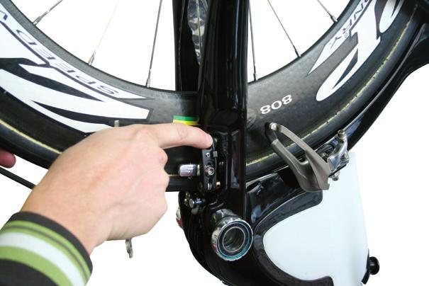
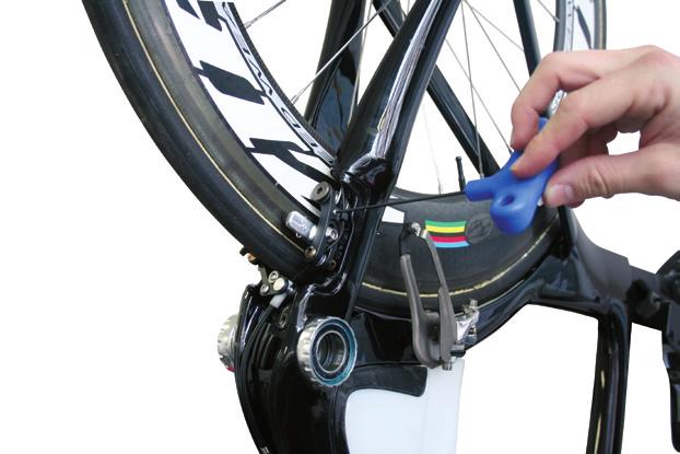
1 P4 CHAINSTAY INTEGRATED ROCKER BRAKE (CSIRB) INSTALLATION TOOLS REQUIRED 2, 2.5, 3, 5 mm allen keys 8, 9 mm open faced cone wrench Pliers Cable cutters Torque wrench MATERIALS REQUIRED: 1 x P4 chainstay integrated rocker brake 1 x Carbon brake stiffener 1 x 5 mm allen key bolts 1 x preset length of flexi cable housing 1 x inline barrel adjuster 1 x brake cable PROCESS: 1. Using the drop out barrel adjusters, first adjust the rear tire s distance to the cut out and center it in between the chain stays (Note: clinchers will have a larger wheel radius on average than tubular wheel. This distance also changes as the width of the tire changes.) If the wheel is not positioned correctly the pads will not contact the braking surface of the rim optimally. (Figure 1) 2. Once the drop out barrel adjusters have been set, remove the wheel to make the rear brake installation easier. 3. Install rocker pivot post using a deep 9 mm cone wrench and torque to 3 Nm. (Note: lube is not needed as the bolts are already coated with thread prep.) (Figure 2) 4. Place the rocker assembly on the rocker pivot post and torque the bolt to 3 Nm of torque with a 2.5 mm allen key (Figure 3) 5. Install the pivot bolt and non-drive side brake arm with a 5 mm allen key, ensuring that the spring is seated on the vertical landings on the frame. When the pivot bolt is tight (3 Nm), the lower washer should spin freely. If it does not spin freely, loosen the pivot bolt and reposition the lower washer before retightening the pivot bolt. (Figure 4) 6. Repeat step 5 with the drive side brake arm. (Figure 5) 7. Insert slave link sleeve into the slave link (Figure 6), rotate non drive side brake arm into the rocker assembly. Install screw through the rocker and sleeve. Torque to 1 Nm with and 2.5 mm allen key. (Figure 7) 8. Rotate brake arms and rockers; they should move freely through their ranges without noticeable binding. 9. With the drive side crank arm removed, insert the rear wheel and set brake pads against the braking surfaces on the wheel. Torque the brake pad bolts to 5 Nm with a 5 mm allen key. (Figure 8) 10. Install the upper portion of the P4 cable system as outlined in P4 cabling service manual. 11. Install the inline barrel cable adjuster onto the rear brake line. The location of this barrel adjuster should be approximately 3 to 4 inches from the top tube entry hole. 12. Set inline cable adjuster to roughly the middle of its travel. 13. Run the rear brake cable until it exits the frame at the bottom bracket area. 14. Install the flexi brake housing over the rear brake cable where it exits the frame and seat it in the rear brake cable BB cable stop. (Note: the flexi brake housing is a preset length. Using other housing or lengths that are longer or shorter will compromise brake function.) 15. Thread the rear brake cable through the plastic cable housing seat on the rocker assembly. 16. Continue to thread the cable between the two washers and through the cable clamp bolt on the drive side brake arm. 17. Set the quick release on the non-drive side brake arm to the closed position. 18. Compress the brake pads against the wheel with your fingers and pull the rear brake cable tight with a pair of pliers, removing any slack. 19. Clamp the cable tight with a 5 mm allen key. (Figure 9) 20. Secure the lower part of the cable fixing bolt with an 8 mm open faced wrench and continue to tighten the cable fixing bolt to 6 Nm of torque using a 5 mm allen key,. (Figure 10) 21. Cut cable to desired length and install cable crimp.
2 P4 DI2 INSTALLATION TIPS - BATTERY HIDDEN INSIDE WATER BOTTLE TOOLS 6,7 mm drill bit Variable speed power drill Hook tool (a spoke with a 180 o bent end) Masking tape X-acto knife Electrical tape PARTS 1 x 10 mm, M5 bolt 1 x M5 nylon lock nut Shimano EW 7972 wiring unit Shimano battery Base A plate(y-7df 98020) PROCEDURE Note: this option renders the water bottle unusable and is not UCI legal. 1. The assembly of the rear brake of the P4 must be completed before the start of this procedure. The bottom bracket cups should be installed but the crank should not. 2. Wrap masking tape around the 1/4 drill bit with the tape 10 mm from the tip of the bit. Wrap the tape around the drill bit until there is a 3 mm build up of tape. This will act as a stopper for the bit so that it only drills 10 mm before the tape bottoms out on the frame. NOTE: If you do not create this stopper, the weight of the drill will potentially cause the drill to hit the opposite side of the frame and compromise the tube. Any failures in this area will not be covered by warranty. 3. In the centerline of the top tube, drill a 7 mm hole, just behind the headset upper bearing cover on a 2011 P4 (Fig.1), or through the left shifter cable entry hole on a P4. 4. Insert the front junction wire into the newly drilled top tube hole, and snake the wire to the bottom bracket exit hole. 5. Insert the hooked tool into the bottom bracket shifter cable exit hole and grasp the wire. Pull the wire out of the bottom bracket cable exit hole. 6. Drill a 6 mm hole into the brake stiffener in position A, and one 7 mm hole in position D (Fig 2). 7. Bolt the bottom bracket junction box through the hole in position A and attach with an M5 nylon lock nut. Position the junction box on an angle similar to Fig 3. Note: Excess cable length can be wound back and forth under the bottom bracket junction box before it is affixed to the brake stiffener. Note: The junction box may sit better against the brake stiffener if the tip is removed. 8. Route the front junction wire from the junction box through the D hole; plug it into the junction wire that was routed through the down tube. 9. Install the brake stiffener onto the frame. 10. Install the rear derailleur onto the rear derailleur hanger and insert the rear derailleur junction wire into the derailleur. 11. Using the adhesive wire covering provided by Shimano, attach the rear derailleur junction wire to the lower surface of the drive-side chain stay. Cut the adhesive covering so that it ends at the brake stiffener (Fig 4). 12. Install the front derailleur onto the front derailleur hanger and insert the front derailleur junction wire into the front derailleur. 13. Using the adhesive cable covering, fasten the front derailleur junction wire to the lateral side of the drive-side chain stay, similar to Fig 5. An additional adhesive piece can be used to attach the front derailleur wire to the seat tube, if length permits. 14. Replace the battery B base plate with the A base plate, which is designed for down tube battery placement. 15. Cut the front portion of the B base plate similar to Fig 6; install on top of the water bottle cage using the water bottle bolts. 16. With the X-acto knife, cut the bottom out of the P4 water bottle, similar to Fig Cut a slot in the drive-side of the water bottle to allow the battery wire to exit the water bottle. 18. Using the adhesive cable covering, fasten the battery wire to lateral side of the seat tube, similar to Fig 5. Note: Excess wiring can be gathered up inside the water bottle. 19. To offer maximum water bottle security, electrical tape can be used to secure the water bottle in the water bottle cage.


3 Figure 1 Figure 2 Figure 3 Figure 5 Figure 4 Figure 6 Figure 7
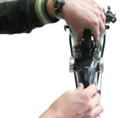
4 P4 Evo CHAINSTAY INTEGRATED ROCKER BRAKE (CSIRB) INSTALLATION TOOLS REQUIRED 2, 2.5, 3, 5 mm hex keys 8 mm open end wrench 9 mm deep hex socket Pliers or cable pulling device Cable cutters Torque wrench Small flathead screwdriver MATERIALS INCLUDED 1 x P4 Evo chainstay integrated rocker brake consisting of: 1 x Non-drive side arm assembly (with quick release attached) 1 x Drive side arm assembly (with link attached) 1 x pre-cut 130 mm length of flexi cable housing 2 x Brake pads (marked L and R) 1 x Rocker pivot post 1 x M4X12 mm slave link mounting screw (2.5 mm hex drive) 1 x Slave link sleeve 1 x M3X8 mm rocker mounting screw (3 mm hex drive) 1 x Carbon brake stiffener 1 x Jagwire Rocket barrel adjuster 1 x Brake cable 1 x Brake cable end crimp Rear race wheel Rear training wheel IDENTIFICATION P4 brakes can be identified by the serial number located on the non-drive side arm. All P4 Evo brakes have a serial number of CS611XXXX or higher. PREPARATION 1. Remove all brake parts from their individual packages. 2. Remove the M5 button head cap screws from the pivot posts in both brake arm assemblies (larger ends) using an M3 hex key; set aside. These are used for mounting the structural cover later in the assembly. 3. Remove the tape from the threaded end of the pivot posts on both brake arm assemblies. 4. Install the left brake pad holder (marked L) on the non-drive side brake arm. The large spherical washer must be next to the pad holder on the inside of the brake arm. The small flat washer and hex cap must be on the outside of the arm. Tighten the hex cap enough to hold the pad in place. (Figure 1) 5. Repeat step 4 with the drive side (R) brake pad holder on the drive side arm. PROCESS 1. Ensure both wheels are true and properly dished. 2. Of the two wheels, select the wheel that has the largest diameter to the edge of the tire. 3. Using the drop out screws, adjust the distance of the rear tire to the seat tube. The optimal position will centre the wheel between the chain stays and have the tire as close to the seat tube as possible without touching. Once the position of the drop out screws has been set, remove the wheel for brake installation. 4. Remove crank arms from the bike. 5. Using a deep 9 mm hex socket, install rocker pivot post; torque to 3 Nm. (Figure 2) Note: Lube is not needed as the bolts are already coated with thread prep. 6. Place the rocker assembly on the rocker pivot post. Add the rocker mounting screw and torque to 3 Nm with a 2.5 mm hex key. The rocker should be aligned with the point of the triangle facing the rear and the cable stop facing the non-drive side. (Figure 2) Note: Do not lube the rocker pivot post. Lube will attract dirt and increase friction. The plastic bushings on the rocker assembly are self lubricating. 7. With a 5 mm hex key, install the pivot bolt and drive side brake arm. Ensure that the spring is seated on the vertical landings of the chain stay and that the
5 lower pivot washer fits around the bottom of the pivot post. The natural tendency will be for the washer to get pinched off center. Using a flathead screwdriver, push the washer until it is no longer pinched. When this is done, torque the pivot bolt to 3 Nm. The lower washer should spin freely. If it does not spin freely, loosen the pivot bolt and reposition the lower washer before retightening the pivot bolt. Repeat with the other brake arm. (Figure 3) 8. Insert the slave link sleeve into the slave link. (Figure 4) 9. Install the slave link screw through the rocker and sleeve. Torque to 1 Nm with a 2.5 mm hex key. (Figure 5) 10. Install each rear wheel and adjust the brake pads to the braking surfaces on each wheel. Torque the brake pad nuts to 5 Nm with a 5 mm hex key. 11. Reinstall the wheel that has the widest rim at the braking surface. 12. Install the Jagwire Rocket cable adjuster into the rearmost ICS-3 top tube entry hole. Install the rear brake cable in the frame through the cable adjuster and out the hole at the bottom bracket. 13. Install the flexi brake housing over the rear brake cable where it exits the frame; position it in the rear brake cable BB cable stop. 14. Thread the rear brake cable through the plastic cable housing seat on the rocker assembly(between the flat washer and the cable clamp on the nondrive side brake arm). 15. Set the quick release on the non-drive side brake arm to the closed position. The closed position of the quick release is with the arrow pointing towards the front of the bike. 16. Press the brake pads against the wheel and pull the rear brake cable tight with a pair of pliers or a cable pulling tool. 17. Tighten the cable fixing bolt to 6 Nm of torque using the 5 mm hex key. 18. Cut the cable and install cable crimp. Tuck the excess cable around the brake post. 19. Squeeze the brake to take up the slack in the brake line. Tighten the Jagwire Rocket barrel adjuster to the desired brake lever travel. 20. Balance the spring tension on the drive side and non-drive side brake arms with a 2 mm hex key to ensure that the brake arms are centered over the rim. Squeeze the brake lever a few times between each adjustment. 21. Insert the front tab of the carbon brake stiffener into the hole at the down tube. 22. Fit the brake stiffener cover over the brake arms; squeeze the brake arms together if necessary. 23. Install the two M5 button head bolts (removed from the pivot posts in the preparation phase) with a 3 mm hex key and torque to 3 Nm. 24. Close the quick release and squeeze brake lever a few times; inspect the installation to ensure that the brake stiffener cover does not interfere with the brake operation. 25. Install the cranks as usual; ensure the brake cable does not contact the chain ring nuts. MOUNTING SCREW DRIVE SIDE ARM ASSY STIFFENER SLAVE LINK NON-DRIVE SIDE ARM ASSY SLAVE LINK SLEEVE ROCKER PIVOT POST ROCKER CABLE CLAMP REAR BRAKE CABLE STOP FLEXI CABLE HOUSING QUICK RELEASE KNOB Brake Parts
6 Spherical side of washer towards pad 1 Nm Toward Non-Drive Side 3 Nm Drive side arm shown, other side similar Figure 1 Figure 2 3 Nm Insert sleeve into link end Figure 3 Figure 4 1 Nm Figure 5
7 P4 DI2 INSTALLATION TIPS - BATTERY MOUNTED UNDER BOTTOM BRACKET TOOLS 5,6,7 mm drill bit Variable speed power drill Hook tool (a spoke with a 180 o bent end) X-acto knife Masking tape PARTS 1 x 10 mm, M5 bolt 1 x M5 nylon lock nut 2 x M4 nylon lock nuts Shimano EW 7972 wiring unit PROCEDURE 1. The assembly of the rear brake of the P4 must be completed before the start of this procedure. The bottom bracket cups should be installed but the crank should not. 2. Wrap masking tape around the 1/4 drill bit with the tape 10 mm from the tip of the bit. Wrap the tape around the drill bit until there is a 3 mm build up of tape. This will act as a stopper for the bit so that it only drills 10 mm before the tape bottoms out on the frame. NOTE: If you do not create this stopper, the weight of the drill will potentially cause the drill to hit the opposite side of the frame and compromise the tube. Any failures in this area will not be covered by warranty. 3. In the centerline of the top tube, drill a 7 mm hole, just behind the headset upper bearing cover on a 2011 P4 (Fig.1), or through the left shifter cable entry hole on a P4. 4. Insert the front junction wire into the newly drilled top tube hole, and snake the wire to the bottom bracket exit hole. 5. Insert the hooked tool into the bottom bracket shifter cable exit hole and grasp the wire. Pull the wire out of the bottom bracket cable exit hole. 6. Drill a 6 mm hole into the brake stiffener in position A, two 5 mm holes in positions B and C, and one 7 mm hole in position D (Fig.2). 7. Bolt the bottom bracket junction box through the hole in position A and attach with an M5 nylon lock nut. Position the junction box on an angle similar to Fig.3. Note: Excess wire length can be wound back and forth under the bottom bracket junction box before it is attached to the brake stiffener. Note: The junction box may sit better against the brake stiffener if the tip of the junction box is removed. 8. Bolt the brake plate through the holes in positions B and C, and secure it with the M4 nylon lock nuts. Note: The battery mounting bolts should be positioned so that they do not contact, or interfere, with the rear brake cable and boss. 9. Route the front junction wire from the junction box through the D hole; plug it into the junction cable that was routed through the down tube. 10. Install the brake stiffener on the frame. 11. Install the rear derailleur on the rear derailleur hanger; insert the rear derailleur junction wire into the derailleur. 12. Using the adhesive wire covering provided by Shimano, fasten the rear derailleur junction wire to the lower surface of the drive-side chain stay. Cut the adhesive covering so that it ends at the brake stiffener (Fig 4). 13. Install the front derailleur onto the front derailleur hanger and insert the front derailleur junction wire into the front derailleur. 14. Using the adhesive cable covering, affix the front derailleur junction wire to lateral surface of the drive side chain stay similar to Fig 5. An additional adhesive piece can be used to secure the front derailleur wire to the seat tube, if length permits.

8 Figure 1 Figure 2 Figure 3 Figure 5 Figure 4

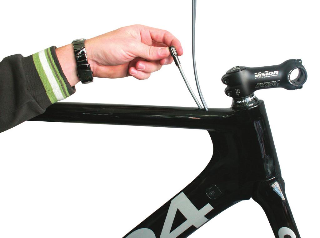
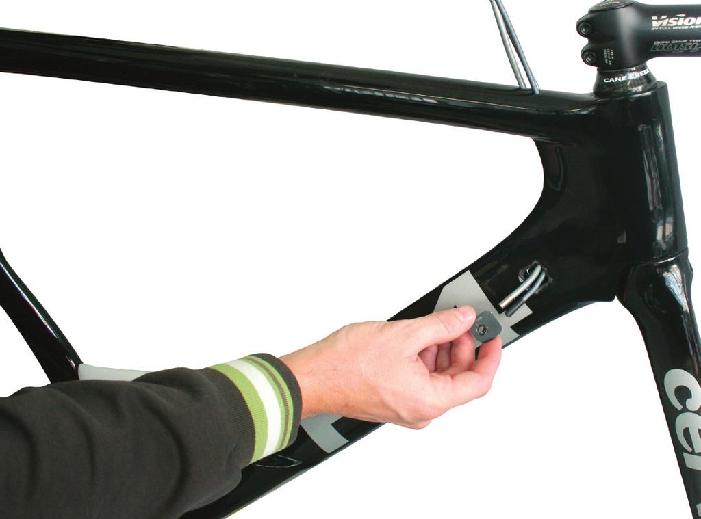
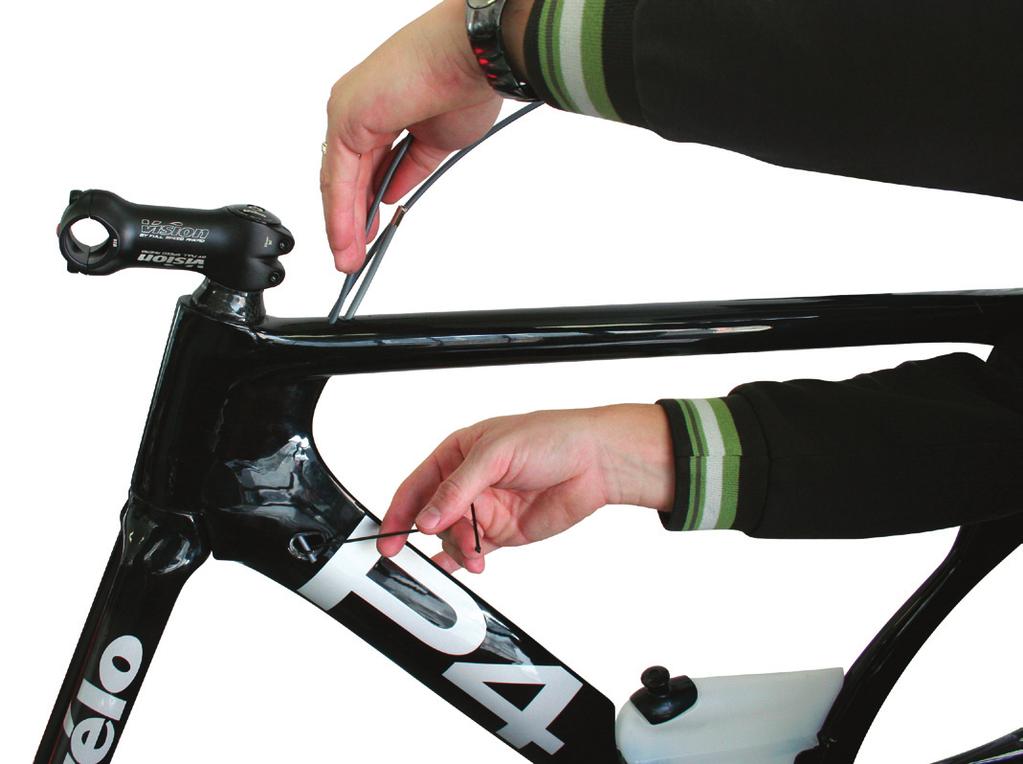
9 P4, S2 AND S3 FRONT CABLE ASSEMBLY MATERIALS REQUIRED: 2 x 24 inch length of 4-5 mm shift cable housing 1 x 15 inch length of 5 mm brake cable housing 2 x shift cable housing end ferules 1 x brake cable housing end ferules Drive side and non-drive side halves of the Cervelo ICS-2 with M4 fi xing bolt 2.5 mm allen key and torque wrench 1 x hook tool, fashioned from a conventional J bend spoke PROCESS: 1. Bend a spoke in the shape pictured in Figure 1 to fashion the hook tool. 2. Take the piece of brake cable housing and curve the last 3 inches slightly. Insert this cable housing into the rear most hole at the front of the top tube so it curves towards the front of the bike. (Note: for thes2/s3 please ignore this step) (Figure 2) 3. Insert about 3 inches into the top tube and twist the cable housing 180 degrees so the housing is now curving towards the rear of the bike. 4. Push the cable housing into the down tube until it passed the holes on the side of the down tube. 5. Insert the hook tool into the drive side ICS hole at the top of the down tube. Catch the cable housing with the hook tool and pull the cable housing out of the top tube until the end is in line with the ICS hole. Pull the cable out of the ICS hole with the hook tool while pushing more cable housing into the top tube. Stop when you have 2-3 inches of cable housing exposed on the drive side. (Figure 3) 6. Take the fi rst piece of the shift cable housing and curve the last 3 inches slightly. Insert this cable housing into the front drive side hole at the front of the top tube so it curves towards the front of the bike. (Figure 4) 7. Repeat steps 3-5. (Figure 5) 8. Take the second piece of the shift cable housing repeat steps and curve the last 3 inches slightly. Insert this cable housing into the front non-drive side hole at the front of the top tube so it curves towards the front of the bike. 9. Repeat steps 3-5. (Figure 6) 10. Place the shifting and brake cable ferrules onto their appropriate cable end. 11. Place the non drive side ICS-2 onto the shift cable housing that exits the non drive side of down tube. Push the extra cable housing up into the frame and insert the ICS into the frame. 12. Place the drive side ICS-2 onto the brake and shifting cable housings that exits the drive side of down tube making sure that the brake housing is inserted into the upper boss and the shift housing is inserted into the lower boss (Note: for the S2/S3 frame will only use the shift cable and not the rear brake cable). Push the extra cable housing up into the frame and insert the ICS-2 into the frame. (Figure 7) 13. Insert the 2.5 mm allen key into the bolt hole of the drive side ICS-2 to ensure both halves of the ICS-2 are aligned. 14. Grease threads of the M4 fi xing bolt, insert into drive side ICS-2 and torque to 1.5 Nm. (Figure 8) 15. Cut the free ends of the shifting and brake cables to their appropriate length to allow the handlebars to turn without binding. (Note: For the P4 the rear brake cable will need an inline barrel adjuster for proper set up of the rear brake) (Figure 9) 16. Proceed to run the shifting and rear cables just as you would on any aero Cervelo frame.


10 Hook tool Brake housing Non-drive side ICS-2 Cable ends Drive side ICS-2 2.5mm M4 ICS-2 fixing bolt Shifter housing Figure 1 Figure 2 Inline barrel adjuster Figure 3


11 Figure 4 Figure 5 Figure 6 Figure 7 1.5Nm Figure 8 Figure 9
 23.")


 28.")
12 22. Loop cable over the hook and under the spring on drive side brake arm so it does not come into contact with the crank s chain ring bolts. (Figure 11) 23. Adjust (shorten) the inline cable adjuster as required to move the pads away from the rim and give the desired engagement point on the brake lever travel. 24. Balance the spring tensions on the drive side and non-drive side brake arms with the 2 mm grub screws to ensure that the brake arms are centered over the rim. Squeeze the brake lever a few times between each adjustment. Spring tension will be higher on the non-drive side brake arm. (Figure 12) 25. To install brake stiffener rotate quick release so that it is perpendicular to the wheel. Insert the BB tab of the brake stiffener into the hole at the front of the cable trench. 26. Fit the stiffener over the brake arms, squeezing the brake arms together to fit the quick release through the slot in the stiffener. (Figure 13) 27. Install the two M5 button head screws with a 3 mm allen key and torque to 3 Nm. (Figure 13) 28. Close the quick release and squeeze brake lever a few times and inspect the installation to ensure that the stiffener does not interfere with the brake operation. 29. Install crank arm ensuring that the rear brake cable does not make contact with the chain ring bolts. 3Nm Figure 1 Figure 2 3Nm 3Nm Figure 3 Figure 4 3Nm Figure 5 Figure 6


13 5Nm 1Nm Figure 7 Figure 8 6Nm Figure 9 Figure 10 Figure 11 Figure 12 Figure 13
Slide on the heat shrink tubing and connect the wire to the color matched cable on the Junction Box, making sure to line up the cable properly
 Manual Routing Di2 Frame Wires Down Tube E-wire Remove the Battery Cover and Hidden Battery compartment from the frame and put aside (Figure 1). Using electrical tape, attach the end of the Down Tube E-wire
P5 SUPPLEMENTARY MANUAL
 P5 SUPPLEMENTARY MANUAL ROUTING DI2 FRAME WIRES Down Tube E-Tube Wire Remove the Battery Cover and Hidden Battery compartment from the frame and set aside. Using electrical tape, attach the end of the
E-118 NEXT : ASSEMBLY GUIDE
 E-118 NEXT : ASSEMBLY GUIDE Revision 5.0-06-01-2016 E-118 NEXT : Table of contents Assembly overview..........................2-4 1. Frame inspection........................5 2. Fork installation.......................6-7
E-118 NEXT 216A: ASSEMBLY GUIDE
 E-118 NEXT 216A: ASSEMBLY GUIDE Revision 6.0-05-03-2017 E-118 NEXT 216A: Table of contents Assembly overview...2-4 1. Frame inspection...5 2. Fork installation...6-7 3. Handlebar installation...8-12 4.
Chrysler 727, 904, 518 Floor Mount Automatic Transmission Shifter Installation Instructions
 Chrysler 727, 904, 518 Mount Automatic Transmission Shifter Installation Instructions Building American Quality With A Lifetime Warranty! TOLL FREE 1-877-469-7440 tech@lokar.com www.lokar.com Release Button
Ford C4 and C6 Floor Mount Automatic Transmission Shifter Installation Instructions
 Ford C4 and C6 Mount Automatic Transmission Shifter Installation Instructions Building American Quality With A Lifetime Warranty! TOLL FREE 1-877-469-7440 tech@lokar.com www.lokar.com Ford C4 and C6 Mount
AmTryke Adult Recumbent Model HP1000 #50-HC-1000
 AmTryke Adult Recumbent Model HP1000 #50-HC-1000 TOOLS Needed for Assembly 5 mm Allen Wrench 8 mm Socket or Wrench 10 mm Socket or Wrench 14 mm Socket or Wrench 15 mm Socket or Wrench 22 mm Socket or Adjustable
AmTryke Adult Recumbent Model JT2000 #50-FC-2000
 AmTryke Adult Recumbent Model JT2000 #50-FC-2000 TOOLS Needed for Assembly 5 mm Allen Wrench 8 mm Socket or Wrench 10 mm Socket or Wrench 14 mm Socket or Wrench 15 mm Socket or Wrench 22 mm Socket or Adjustable
Installation Manual TWM Performance Short Shifter Cobalt SS/SC, SS/TC, HHR SS, Ion Redline and Saab 9-3
 Page 1 Installation Manual TWM Performance Short Shifter Cobalt SS/SC, SS/TC, HHR SS, Ion Redline and Saab 9-3 Please Note: It is preferable to park on a flat surface, as you will have to engage and disengage
Go-ped ESR750 / ESR750EX Rear Brake Installation Instructions
 Go-ped ESR750 / ESR750EX Rear Brake Installation Instructions This kit provides all the parts you need to install a rear brake on your ESR750 or ESR750EX. It will not work on an ESR Sport, or other Go-ped
Technical Support (707)
") Installation Instructions CONSOLE MEGASHIFTER Fits: 1982-1992 Camaro & Firebird w/automatic Transmission *except 1988-1992 Firebird Formula Model Catalog # 80692 WORK SAFELY! For maximum safety, perform
Installation Instructions CONSOLE MEGASHIFTER Fits: 1982-1992 Camaro & Firebird w/automatic Transmission *except 1988-1992 Firebird Formula Model Catalog # 80692 WORK SAFELY! For maximum safety, perform
How to install shifter style lever (Gen 1 & Gen
 How to install shifter style lever (Gen 1 & Gen 2) Written By: The Hive 2017 service.bythehive.com Page 1 of 10 TOOLS: T25 Torx wrench (1) Cable cutter (1) M3 Hex wrench (1) 2017 service.bythehive.com
PRO RATCHET UNIVERSAL SHIFTER
 Installation Instructions PRO RATCHET UNIVERSAL SHIFTER Fits: GM, Ford and Chryslers w/automatic Transmission See Application Guide for Specific Vehicles Catalog # 80842 WORK SAFELY! For maximum safety,
Installation Instructions. QuickSilver Shifter. Fits: GM, Ford, Chrysler Transmissions See Application Guide for Specific Applications Part # 80683
 Installation Instructions QuickSilver Shifter Fits: GM, Ford, Chrysler Transmissions See Application Guide for Specific Applications Part # 80683 WORK SAFELY! For maximum safety, perform this installation
GM Floor Mount Automatic Transmission Shifter Installation Instructions
 GM Mount Automatic Transmission Shifter Installation Instructions Building American Quality With A Lifetime Warranty! TOLL FREE 1-877-469-7440 tech@lokar.com www.lokar.com GM Mount Automatic Transmission
Z-Gate Universal Shifter
 Installation Instructions Z-Gate Universal Shifter Fits: GM, Ford, Lincoln and Chrysler Transmissions See Application Guide for Specific Applications Part #80681 Rev 06/01/2018 WORK SAFELY! For maximum
J&M Mustang Rear Adjustable Lower Control Arms Installation Guide (99-04)
") J&M Mustang Rear Adjustable Lower Control Arms Installation Guide (99-04) 1. Required Tools: 1.1. 3/8 ratchet 1.2. 1/2 ratchet 1.3. 18mm deep socket 1.4. 18mm standard socket (optional) 1.5. 19mm open
J&M Mustang Rear Adjustable Lower Control Arms Installation Guide (99-04) 1. Required Tools: 1.1. 3/8 ratchet 1.2. 1/2 ratchet 1.3. 18mm deep socket 1.4. 18mm standard socket (optional) 1.5. 19mm open
Installation Instructions Z-Gate Shifter
 Installation Instructions Z-Gate Shifter Part Number 80681 1998, 2001 by B&M Racing and Performance Products The B&M Z-Gate shifter can be used in vehicles equipped with most popular three speed automatic
Assembly Instructions
 www.rockymounts.com TandemMount R4 Installation Manual Guidelines/Restrictions: - This carrier is intended for Thule rectangular and Yakima round bars only. - Bicycles must be equipped with quick release
INSTALLATION & OWNER S MANUAL
 Rev. C p. 1 of 21 INSTALLATION & OWNER S MANUAL F5205 HARD SIDED CAB KIT INSTALLATION & OWNER S MANUAL The contents of this envelope are the property of the owner. Be sure to leave with the owner when
This LED flashtube kit covers models 400, 404, 500, 504, 600, 680 & 506.
 L.E.D. INSTRUCTIONS I D T S O T U B I R M O C R Y N A P Kit contains: This LED flashtube kit covers models 400, 404, 500, 504, 600, 680 & 506. For the power supply: 1-LED power supply circuit board, 2
Chrysler 727, 904, and 518 Automatic Trans Mount Shifter Installation Instructions
 Chrysler 727, 904, and 518 Automatic Trans Mount Installation Instructions Building American Quality With A Lifetime Warranty! TOLL FREE 1-877-469-7440 tech@lokar.com www.lokar.com Chrysler 727, 904, and
YOU MUST WEAR SAFETY GLASSES DURING EACH STEP OF THESE INSTRUCTIONS
 Machine Racer: Rally Preparation 1. Print the Working Drawing of the design you created and simulated in the Mousetrap Car 2.0 STEM Application. You can find your Working Drawing in the "Outputs" tab of
Conflicts: Vehicles without a sunroof Vehicles with a single sunroof
 Toyota Sienna (Dual Sunroof) 2011-10.2 Overhead Video Part Number: 00016-00110 00016-00110-17 Fit Kit 00016-00120 00016-00120-17 Fit Kit Accessory Code: ED5 Conflicts: Vehicles without a sunroof Vehicles
Light Truck MegaShifter
 Installation Instructions Light Truck MegaShifter The B&M Light Truck Megashifter shifter is designed to be used in most light trucks equipped with most popular three speed or four speed automatic transmissions.
Powerglide Automatic Floor Mount Shifter Installation Instructions
 Powerglide Automatic Mount Installation Instructions Building American Quality With A Lifetime Warranty! TOLL FREE 1-877-469-7440 (865) 966-2269 FAX (865) 671-1999 tech@lokar.com www.lokar.com Powerglide
Final Assembly Instructions Portside Cruiser
 Final Assembly Instructions Portside Cruiser Thank you for buying your new bicycle from L.L.Bean. Read these instructions carefully before beginning the final assembly. Prior to shipping, our expert cycling
This is the Unpacking Guide for the Optibike Pioneer Allroad electric bicycle. The Guide provides information required to remove the Allroad from the
 This is the Unpacking Guide for the Optibike Pioneer Allroad electric bicycle. The Guide provides information required to remove the Allroad from the box and assemble it. If you have not assembled a bicycle
Ford AOD-4R70W-AODE Cable Operated Shifter Installation Instructions
 Ford AOD-4R70W-AODE Cable Operated Shifter Installation Instructions Building American Quality With A Lifetime Warranty! TOLL FREE 1-877-469-7440 tech@lokar.com www.lokar.com Ford AOD-4R70W-AODE Cable
Final Assembly Instructions: Runaround Cruiser
 Final Assembly Instructions: Runaround Cruiser Thank you for buying your new bicycle from L.L.Bean. Read these instructions carefully before beginning the final assembly. Prior to shipping, our expert
TCI FastGate Shifter Installation Instructions
 151 INDUSTRIAL DRIVE ASHLAND, MISSISSIPPI 38603 http://www.tciauto.com TELEPHONE: 662-224-8972 FAX LINE: 662-224-8255 E-MAIL: tech@tciauto.com TCI 616541 FastGate Shifter Installation Instructions The
USER'S MANUAL and INSTALLATION GUIDE
 AM Inlet Series 8" and 2" baffle AM0896GS AM296GS USER'S MANUAL and INSTALLATION GUIDE TABLE OF CONTENTS Section Page...Requirements for Installation...2 2...Unpacking the AirManager... 3-5...Exploded
Technical Support (707)
") Installation Instructions UNIMATIC SHIFTER Fits: GM, Powerglide, Ford and Chrysler Transmissions See Application Guide for Specific Vehicles Catalog # 80775 WORK SAFELY! For maximum safety, perform this
Installation Instructions UNIMATIC SHIFTER Fits: GM, Powerglide, Ford and Chrysler Transmissions See Application Guide for Specific Vehicles Catalog # 80775 WORK SAFELY! For maximum safety, perform this
E-118 NEXT : ASSEMBLY GUIDE. revision
 E-118 NEXT : ASSEMBLY GUIDE revision 2.0-2014-10-28 E-118 NEXT : Table of contents Assembly overview..........................2-4 1. Frame inspection........................5 2. Fork installation.......................6-7
RHINO SUSPENSION SYSTEM INSTALLATION INSTRUCTIONS
 PARTS INCLUDED: 2 FRONT UPPER A-ARMS 2 FRONT LOWER A-ARMS 2 UNI-BALL JOINTS 2 UNI-BALL JOINT STUDS 2 UNI-BALL JOINT CAPS 2 RETAINING RINGS 1 FRONT SHOCK ASSEM. 2 DELRON STEERING STOPS 2 SHOCK MOUNT SPACERS
Installation Manual TWM Performance Short Shift Kit Stage 1 and Stage 2 MazdaSpeed 6
 Page 1 Installation Manual TWM Performance Short Shift Kit Stage 1 and Stage 2 MazdaSpeed 6 Please Note: It is preferable to park on a flat surface, as you will have to engage and disengage the hand brake
Installation Instructions QUICKSILVER CONSOLE SHIFTER Fits: Chevelle / El Camino
 WORK SAFELY! For maximum safety, perform this installation on a clean, level surface and with the engine turned off. Place blocks or wedges in front of and behind both rear wheels to prevent movement in
Ford AOD-4R70W-AODE Cable Operated Shifter Installation Instructions
 Ford AOD-4R70W-AODE Cable Operated Shifter Installation Instructions Building American Quality With A Lifetime Warranty! TOLL FREE 1-877-469-7440 tech@lokar.com www.lokar.com Ford AOD-4R70W-AODE Cable
PARTS TOOLS. Set Screw. Washer (2) Blue Bushing (2) Black Bushing (2) B&M Short Throw Shifter. Jam Nut Grease. Retaining Ring (2) Insert (2)
 Blue Bushing (2) Black Bushing (2) B&M Short Throw Shifter. Jam Nut Grease. Retaining Ring (2) Insert (2)") Installation Instructions SHORT THROW SHIFTER Fits: Porsche Boxter, Boxter S, 911, 996 Cayman & Cayman S models See Application Guide for specific year ranges and engine sizes Catalog # 45135 WORK SAFELY!
Installation Instructions SHORT THROW SHIFTER Fits: Porsche Boxter, Boxter S, 911, 996 Cayman & Cayman S models See Application Guide for specific year ranges and engine sizes Catalog # 45135 WORK SAFELY!
R-SE JK 4 DOOR Step Slider Install Instructions. *If any parts listed are missing or damages please call prior to install.
 R-SE JK 4 DOOR Step Slider Install Instructions Parts List: 1 Divers side slider assembly 1 Passenger side slider assembly 1 wiring harness 1 control box 2 spacers 2 LED lights (optional) 10 SS Button
Final Assembly Instructions: Bikes with Threadless Headsets
 Final Assembly Instructions: Bikes with Threadless Headsets Thank you for buying your new bicycle from L.L.Bean. Read these instructions carefully before beginning the final assembly. Prior to shipping,
HiBoy Maverick/Commander Doors Part # HiBoy4 Maverick/Commander Doors Black
 Racing 3191 N Washington St. Suite 2 Chandler, AZ 85225 1 (800) 708-9803 http://www.racing.com HiBoy Maverick/Commander Doors Part # 07-2001 HiBoy4 Maverick/Commander Doors Black Congratulations on your
SUT-450-I ASSEMBLY REQUIREMENTS
 SUT-450-I Torque wrench, carpenters square, wire cutters, Phillips screwdriver, 7/16, 9/16, and 3/4 combination wrenches, ratchet, 9/16,3/4,13/16, and 7/8 sockets. ASSEMBLY REQUIREMENTS *Torque all T-bolt
CHAINGUARD REGAL ST COLOR
 DESOTO/ REGAL HAULER PARTS LIST Item Part # Description QTY Item Part # Description QTY 1 11871 REFLECTOR KIT TRIKE 1 32 11764 FENDER BRACE 24" MWT 1 2 12199 SCREW #14 x 3/4 4 33 12176 NUT5/16-24 HEX 2
H15P. Toyota Hilux A-DECK Dual Cab
 Toyota Hilux A-DECK Dual Cab Page 1 of 14 Fitting Instructions Part Number H15 Toyota Hilux A-DECK Dual Cab 2015+ To suit Sports Bars Check contents of kit before commencing fitment and report any discrepancies
1989 Jeep Cherokee. STEERING COLUMN' '1989 STEERING Jeep Steering Columns STEERING COLUMN STEERING Jeep Steering Columns
 STEERING COLUMN 1989 STEERING Jeep Steering Columns DESCRIPTION All models use collapsible steering columns. All columns have integral ignition switch and locking device. Optional tilt wheel is available
Toyota Prius Interior Light Upgrade
 Toyota Prius 2012- Interior Light Upgrade Part Number 00016-00095 Accesory Code: IL2 Conflicts Kit Contents Item # Quantity Reqd. Description 1 1 Y Adapter 2 1 Wire harness 3 1 Hardware Kit 4 2 White Light
CHAINGUARD REGAL ST COLOR
 DESOTO/ REGAL HAULER PARTS LIST Item Part # Description QTY Item Part # Description QTY 1 11871 REFLECTOR KIT TRIKE 1 32 11762 FENDER BRACE 20" MWT 1 2 12199 SCREW #14 x 3/4 4 11764 FENDER BRACE 24" MWT
Multistrada (MTS) Tank Installation Notes. Tools Required. Phase 1: Remove Fairings. Phase 2: Remove Fuel Tank
 Tank Installation Notes. Tools Required. Phase 1: Remove Fairings. Phase 2: Remove Fuel Tank") The California Cycleworks MTS tank provides an aftermarket alternative to the OEM nylon fuel tanks as used on aircooled Desmodue Ducati Multistrada 1100, 1000, and 620 models. This fuel tank is NOT for
The California Cycleworks MTS tank provides an aftermarket alternative to the OEM nylon fuel tanks as used on aircooled Desmodue Ducati Multistrada 1100, 1000, and 620 models. This fuel tank is NOT for
Installation of Barricade Flat Style Fender Flare Kit (97-06 Wrangler TJ)
") Installation of Barricade Flat Style Fender Flare Kit (97-06 Wrangler TJ) Installation Time: 3-4 Hours Tools Required: 8mm wrench 8mm socket drive #1 Phillips screw driver Pliers Pry bar Electric drill
Installation of Barricade Flat Style Fender Flare Kit (97-06 Wrangler TJ) Installation Time: 3-4 Hours Tools Required: 8mm wrench 8mm socket drive #1 Phillips screw driver Pliers Pry bar Electric drill
Installation Instructions COMPETITION/PLUS SHIFTER Ford Mustang MT82 6-Speed Manual Transmission Catalog#
 Installation Instructions COMPETITION/PLUS SHIFTER 2015-2017 Ford Mustang MT82 6-Speed Manual Transmission Catalog# 3916037 Rev. 00 WORK SAFELY! For maximum safety, perform this installation on a clean,
Installation Instructions Unimatic Shifter
 Installation Instructions Unimatic Shifter Universal Shifter for Automatic Transmissions Part Number 80775 2010, 2000 by B&M Racing & Performance Products The B&M Unimatic is a universal shifter that will
Q15P. Mitsubishi MQ Triton Dual Cab
 Mitsubishi MQ Triton Dual Cab Page 1 of 12 Fitting Instructions Part Number Mitsubishi MQ Triton Dual Cab 2015+ To suit Sports Bars Check contents of kit before commencing fitment and report any discrepancies
Stealth Pro Ratchet Shifter
 Installation Instructions Stealth Pro Ratchet Shifter Part Number 81120 & 81121 (see www.bmracing.com for the latest technical product information) 2010, 2006 by B&M Racing and Performance Products The
Installation Instructions StarShifter
 Installation Instructions StarShifter Part Number 80675 2000 by B&M Racing & Performance Products LLC The B&M StarShifter can be used in vehicles equipped with most popular three speed automatic transmissions.
2010+ Audi B8 S4/S5 3.0T S-FLO Intake Kit INSTALLATION GUIDE FOR RACING USE ONLY
 INSTALLATION GUIDE 2010+ Audi B8 S4/S5 3.0T S-FLO Intake Kit FOR RACING USE ONLY Congratulations on your purchase of the AWE Tuning S-FLO Intake for the 2010+ Audi B8 S4 and B8 S5 3.0T. Exquisite build
INSTALLATION & OWNER S MANUAL
 INSTALLATION & OWNER S MANUAL CAB INSTALLATION INSTRUCTIONS JOHN DEERE 4000 SERIES (4500/4600/4700) (4510/4610/4710) (4120/4320/4520/4720) HARD SIDED CAB ENCLOSURE (p/n 1JD4120AS) SOFT SIDED CAB ENCLOSURE
Chrysler 45RFE Tailmount Automatic Transmission Shifter Installation Instructions
 Chrysler 45RFE Tailmount Automatic Transmission Installation Instructions Building American Quality With A Lifetime Warranty! TOLL FREE 1-877-469-7440 tech@lokar.com www.lokar.com Chrysler 45RFE Tailmount
Installation Instructions
 Installation Instructions ELECTRIC CONVERSION KIT 3 ALUMINUM ROLL TUBE IMPORTANT: This Electric Conversion Kit has been designed for systems with a 3 aluminum roll tube. It is assumed that the tarping
Specification Item Number / Model Name CK-5001T / Metropolis Patterson Transmission Crankset
 CK-5001T Metropolis Patterson Transmission Crankset Installation Instructions Published May, 2015. ZSP001.v4 Full Speed Ahead Introduction Congratulations on your Full Speed Ahead product. Please read
Installation Manual TWM Performance Kia Forte Short Shifter
 Installation Manual TWM Performance Kia Forte 2009+ Short Shifter Begin the installation by parking on a flat surface, as you will have to engage and disengage the hand brake and shift from gears to neutral.
CK-5000T Metropolis Patterson Transmission Crankset Installation Instructions Published Jul, ZSP001.v3 Full Speed Ahead
 CK-5000T Metropolis Patterson Transmission Crankset Installation Instructions Published Jul, 2011. ZSP001.v3 Full Speed Ahead Introduction Congratulations on your Full Speed Ahead product. Please read
Installation Instructions Unimatic Shifter
 Installation Instructions Unimatic Shifter Universal Shifter for Automatic Transmissions Part Number 80775 2000 by B&M Racing & Performance Products LLC The B&M Unimatic is a universal shifter that will
1. General Safety Information. Silvio V2.0 Assembly Instructions. Assembly. Adjust to the rider.
 Silvio V.0 Assembly Instructions support@cruzbike.com. General Safety Information WARNING to avoid serious injuries:. If you are unsure about fitting, testing and adjusting brakes or gearing on a bicycle,
MM Rear Coil-Over Kit - Bilstein Shocks (MMCO-3)
") 3430 Sacramento Dr., Unit D San Luis Obispo, CA 93401 Telephone: 805/544-8748 Fax: 805/544-8645 www.maximummotorsports.com MM Rear Coil-Over Kit - Bilstein Shocks (MMCO-3) Read all instructions before
3430 Sacramento Dr., Unit D San Luis Obispo, CA 93401 Telephone: 805/544-8748 Fax: 805/544-8645 www.maximummotorsports.com MM Rear Coil-Over Kit - Bilstein Shocks (MMCO-3) Read all instructions before
Installation Instructions Table of Contents
 Installation Instructions Table of Contents Pre- Installation of Garage Storage Lift 2 Layout the Garage Storage Lift 3 Installing the strut Channels 3 Install the Drive Assembly 5 Install the Drive Shaft
Installation Instructions for the EVO3 Height-Adjustable Ultimate Short Shifter. for F80 M3 and F82 M4
 Installation Instructions for the EVO3 Height-Adjustable Ultimate Short Shifter for 2013+ F80 M3 and F82 M4 part number USSF80 Thank you for purchasing the Ultimate Shift Kit. Please read these directions
C15C C15C. Page 1 of 20
 2 x Lid Front Hinge 1135 8 x M8 Bolt 8 x M8 Washer (3mm Thick) 4 x M6 Large washers 4 x M6 Spring washers 4 x M6 x 40mm Bolts 6 x M6 20mm Bolts 6 x M6 Washers 20 x Screws 2 x Lid mount gas strut bracket
CorkSport ort Mazda 3 Adjustable Shifter Mazdaspeed 3, Mazda 3 6-speed and Mazda3 SkyActiv 6-speed
 Part # Axl-6-963 CorkSport ort Mazda 3 Adjustable Shifter 2010-2013 Mazdaspeed 3, 2010-2013 Mazda 3 6-speed and 2012-2013 Mazda3 SkyActiv 6-speed Pre-Installation Notes: The CorkSport Adjustable Short
Installation Instructions Right Hand Drive Megashifter
 Installation Instructions Right Hand Drive Megashifter Part Number 80685 1995, 2001, 2006, 2010 by B&M Racing & Performance Products The B&M Right Hand Drive Megashifter is designed specifically for vehicles
(2) 10mm Quick Release Bolts with Pivot Washers (4) 10mm Flat Washers (2) 10mm Nylon Lock Nuts. (4) 10mm Plastic Washers
 10mm Quick Release Bolts with Pivot Washers (4) 10mm Flat Washers (2) 10mm Nylon Lock Nuts. (4) 10mm Plastic Washers") PARTS LIST: EXTREME GRILLE GUARD 1 Extreme Heavy Duty Grille Guard 2 10mm Cam Lever Quick Release Bolts with Special Pivot Washer 1 Driver/left Frame Mounting Bracket 4 10mm x 24mm OD x 2.2mm Flat Washers
PARTS LIST: EXTREME GRILLE GUARD 1 Extreme Heavy Duty Grille Guard 2 10mm Cam Lever Quick Release Bolts with Special Pivot Washer 1 Driver/left Frame Mounting Bracket 4 10mm x 24mm OD x 2.2mm Flat Washers
Short Shifter Installation Instructions Miata 6-Speed manual
 Tools required: 10mm deep socket long extension ratchet small flathead screwdriver phillips-head screwdriver Short Shifter Installation Instructions 2006-14 Miata 6-Speed manual IMPORTANT NOTE: This shifter
5.5 Wheel drive (wheel pilots only)
") Chapter 5: Installing the ST4000+ 61 5.5 Wheel drive (wheel pilots only) The Raymarine wheel drive will fit 3, 4, 5, 6, 7 or 8 spoke wheels. It is designed to operate with steering systems with between
Chapter 5: Installing the ST4000+ 61 5.5 Wheel drive (wheel pilots only) The Raymarine wheel drive will fit 3, 4, 5, 6, 7 or 8 spoke wheels. It is designed to operate with steering systems with between
Photo 1. Shift pattern gate plate
 Installation Instructions MAGNUM GRIP STREET BANDIT SHIFTER Fits: GM, Chrysler, and Ford Automatic Transmissions See Application Guide for Specific Vehicles Catalog # 81050 WORK SAFELY! For maximum safety,
2015 Current F150/Raptor Venom Side Steps Installation Instructions
 2015 Current F150/Raptor Venom Side Steps Installation Instructions PREPARATION STEPS 1. Disconnect the negative terminal on the battery. Park the vehicle on level ground and set the emergency brake. 2.
Installation Instructions Supertop NX Twill
 Installation Instructions Supertop NX Twill Vehicle Application: Jeep Wrangler Unlimited 2007-current Part Number 54823 Installation Tips Before you begin installing your new Supertop NX Twill, please
Rekluse Motor Sports. The z-start Clutch CRF 250X. Installation Guide Copyright 2002 Rekluse Motor Sports z-start Revision RMS116 CRF 250X
 Rekluse Motor Sports The z-start Clutch CRF 250X Installation Guide Copyright 2002 Rekluse Motor Sports z-start Revision 3.000 RMS116 CRF 250X 191-216 Manual Revision: 103105 Rekluse Motor Sports, inc.
Assault Air Bike Assembly Instructions
 Assault Air Bike Assembly Instructions Tools Needed: Box Cutter 6mm Hex Wrench Phillips Screw Driver 13mm Wrench 22mm Wrench 15mm Wrench Step 1: Lay the Assault Airbike Bike box on the ground. Step 3:
PLOW MOUNT GLACIER PRO KIT
 PLOW MOUNT GLACIER PRO KIT P/N 2880262 APPLICATION FOR USE WITH THE GLACIER PRO MID-SIZE PLOW SYSTEM (P/N 2880260) ON 2015 AND NEWER RZR 00 MODELS BEFORE YOU BEGIN Read these instructions thoroughly and
4L80E Automatic Trans Mount Shifter Installation Instructions
 4L80E Automatic Trans Mount Installation Instructions Building American Quality With A Lifetime Warranty! TOLL FREE 1-877-469-7440 tech@lokar.com www.lokar.com 4L80E Automatic Trans Mount Installation
Times-2 Speed Files INSTALLATION INSTRUCTIONS
 Times-2 Speed Files INSTALLATION INSTRUCTIONS AURORA from RICHARDS-WILCOX, INC. 600 South Lake Street Aurora, Illinois 60506 Phone: 630-897-6951 Fax: 630-897-6994 Toll Free: 800-277-1699 TIMES-2 SPEED
INSTALLATION INSTRUCTIONS
 INSTALLATION INSTRUCTIONS Part# 22-7810 Add On Kit for Your ADS System Contents: Complete Install Kit for Your ARB CKMTA12V Compressor For the most up-to-date instructions please visit www.updownair.com
EVO-1162 EVO Tailgate Tire Carrier
 EVO-1162 EVO Tailgate Tire Carrier Bill of Materials EVO-1162 Tailgate Tire Carrier Part number Description Quantity EVO-12161 EVO Tailgate Tire Carrier 1 EVO-12162 Bolt Plate 1 EVO-12163 Wheel Mount 1
69-74 VW Beetle IRS Rear Kit Part No
 www.airliftcompany.com 69-74 VW Beetle IRS Rear Kit Part No. 75615 MN-476 (01102) ECN 3455 Please read these instructions completely before proceeding with installation A C B E D AA F F ITEM QTY. PART
GP1-R FULL EXHAUST SUZUKI GSX-R600 / GSX-R
 THIS EXHAUST SYSTEM IS DESIGNED FOR USE IN CLOSED COURSE RACING ONLY, AND IS NOT INTENDED FOR PUBLIC HIGHWAY USE. IN THE STATE OF CALIFORNIA, IT IS ILLEGAL TO MODIFY THE EMISSION CONTROL SYSTEM ON ANY
Installation Instructions
 Installation Instructions Jeep JK 2-Door (2011 Present) Mounting Bracket and Air Line System Kit for ARB On-Board Twin Air Compressor (CKMTA12) Made in the USA Kit Contents: 1 Flat Bracket 1 Formed Bracket
1. Get fork mounted in stand. You can leave it in the bike, but you must remove the wheel and front brake.
 Tools Needed: Bike stand Lint free shop Towels 1.5mm Allen Key Pick Set Grease (We recommend Slick Honey) Oil Measuring Cup (with cc Scale) Small Metal Drift Shop Vise Oil Bucket 13mm Deep Socket (6 point)
Revised BX-1000 BLACK MAX
 Revised 8-22-12 BX-1000 BLACK MAX PLEASE READ THROUGH THE ENTIRE MANUAL BEFORE INSTALLING YOUR BRAKE SYSTEM WARNING - DO NOT USE BRAKE FLUID - USE ATF HYDRAULIC FLUID ONLY **IMPORTANT** DO NOT USE ANY
Safety First. Please remember to always use SAFE shop practices when performing all service procedures.
 Safety First Please remember to always use SAFE shop practices when performing all service procedures. 2006 Update Manual January 2006 Country Clipper 2006 Update Manual Index Joystick Kill Switch Oil
Installation Instructions Sport Shifter
 The B&M Sport Shifter can be used in vehicles equipped with most popular three speed or four speed automatic transmissions. It is equipped with neutral safety and backup light switches, transmission brackets
 INSTALLATION INSTRUCTIONS Accessory ACCESSORY HANDSFREELINK Application 2010 CR-V Publications No. AII 42587 Issue Date AUG 2009 PARTS LIST HFL Attachment Kit P/N 08E02-SWA-130 (Ivory) P/N 08E02-SWA-170
INSTALLATION INSTRUCTIONS FOR MK4 VOLKSWAGEN JETTA (BORA) /GOLF 1.8T, 2.0L, VR6, & R32 MODELS ALSO FITS ALL MODELS OF SEAT LEON & TOLEDO
 /GOLF 1.8T, 2.0L, VR6, & R32 MODELS ALSO FITS ALL MODELS OF SEAT LEON & TOLEDO") CI100001 INSTALLATION INSTRUCTIONS FOR 1999.5-2005 MK4 VOLKSWAGEN JETTA (BORA) /GOLF 1.8T, 2.0L, VR6, & R32 MODELS ALSO FITS ALL MODELS OF SEAT LEON & TOLEDO Thank you for choosing to purchase a Carbonio
CI100001 INSTALLATION INSTRUCTIONS FOR 1999.5-2005 MK4 VOLKSWAGEN JETTA (BORA) /GOLF 1.8T, 2.0L, VR6, & R32 MODELS ALSO FITS ALL MODELS OF SEAT LEON & TOLEDO Thank you for choosing to purchase a Carbonio
Installation Instructions Pro Bandit Shifter Fits: GM Powerglide Automatic Transmissions
 Installation Instructions Pro Bandit Shifter Fits: 1962-1973 GM Powerglide Automatic Transmissions Part # 80793 WORK SAFELY! For maximum safety, perform this installation on a clean, level surface and
TH200 & TH200-4R Automatic Trans Mount Shifter Installation Instructions
 TH200 & TH200-4R Automatic Trans Mount Installation Instructions Building American Quality With A Lifetime Warranty! TOLL FREE 1-877-469-7440 (865) 966-2269 FAX (865) 671-1999 tech@lokar.com www.lokar.com
E-LIFT II+ SYSTEM WITH SPRING LEVER FOR A-SERIES AND FULL FRAME LOOMS
 Congratulations on your purchase of the E-Lift II+ system. This system replaces the action of treadling, eliminating leg strain and fatigue. When you activate the Foot Switch, the motor turns, and selected
TH350 Automatic Trans Mount Shifter Installation Instructions
 TH350 Automatic Trans Mount Installation Instructions Building American Quality With A Lifetime Warranty! TOLL FREE 1-877-469-7440 (865) 966-2269 FAX (865) 671-1999 tech@lokar.com www.lokar.com TH350 Automatic
Short Shifter Installation Instructions For Miata, 6-speed Manual Transmission
 Short Shifter Installation Instructions For 2006-15 Miata, 6-speed Manual Transmission PART# 994-060 Required tools: 10mm deep socket Long extension Ratchet Small flathead screwdriver Phillips-head screwdriver
Technical Support Line: (952) Hanover Ave. Lakeville, MN
 Hanover Ave. Lakeville, MN") Technical Support Line: (952) 985-5675 Email: Sales@QA1.net 21730 Hanover Ave. Lakeville, MN 55044 www.qa1.net INSTALLATION INSTRUCTIONS QA1 1967-1979 Mopar A-Body Rear 6 link Conversion System QA1 p/n
Technical Support Line: (952) 985-5675 Email: Sales@QA1.net 21730 Hanover Ave. Lakeville, MN 55044 www.qa1.net INSTALLATION INSTRUCTIONS QA1 1967-1979 Mopar A-Body Rear 6 link Conversion System QA1 p/n
Part Number: S-H-BAG-8 & S-H-8-RFEN Description: Saddlebags & Rear Fender / Undertail Fitment: Suzuki GSX 1300-R Hayabusa Revision: 1
 Part Number: S-H-BAG-8 & S-H-8-RFEN Description: Saddlebags & Rear Fender / Undertail Fitment: 2008-2009 Suzuki GSX 1300-R Hayabusa Revision: 1 Tools Required Phillips head screwdriver Small screwdriver
INSTALLATION & OWNER S MANUAL
 Rev. B, p. 1 of 25 INSTALLATION & OWNER S MANUAL POLARIS RANGER RCS (for models XP or HD) (for model years 2009-) cab without doors kit (p/n 1POLRCWD) cab with doors kit (p/n 1POLRC) doors only kit (p/n