SUT-450-I ASSEMBLY REQUIREMENTS
|
|
|
- Meryl McCarthy
- 5 years ago
- Views:
Transcription

1 SUT-450-I Torque wrench, carpenters square, wire cutters, Phillips screwdriver, 7/16, 9/16, and 3/4 combination wrenches, ratchet, 9/16,3/4,13/16, and 7/8 sockets. ASSEMBLY REQUIREMENTS *Torque all T-bolt nuts to foot pounds. *Check all lights before towing. *Tire pressure not to exceed recommendation on serial tag. *Re-torque wheel nuts after first 25 miles to 80 ft pounds and periodically thereafter. Failure to follow the assembly instructions could result in serious injury or death. Incorrect assembly or modifications to your trailer will void any specific or implied warranty. For questions or assistance assembling your trailer call
 6 padded")

2 UNPACK AND IDENTIFY THE FOLLOWING PARTS. Front tongue splice plate (4) 6 padded cradle rear tongue Front cross arm side rails spring assemblies rear cross arm 2


3 Wheels fenders axle Bow pads transom board & slotted bracket winch post light box 3


4 U-bolt kit hardware bag spare parts Skid clearance light brackets tail light brackets harness 4
 winch post")

5 16) Slotted L brackets 2) bow mounting brackets 2) winch post diagonal brace Insert splice plate into the underside of rear tongue section as shown. 5


6 Loosen nuts on both sides of the front tongue section and slide them forward. These will be used later in the assembly process. There should be three on each side. Align the rear tongue section with splice plates to the back edge of the front tongue section. Once in position, slide the bottom splice plate over and center it. 6


7 Tighten nuts on the bottom splice plate. Also, make sure there is no gap between the two tongue sections. Shown up side down At this point slide both side splice plates over and center. 7


8 Once plates are in position with no gaps, tighten all nuts. Locate the rear cross arm. On each side there are two T-bolts and nuts. Remove the outer nuts on both ends. The two inside T-bolts are extra to be used when inner bunk brackets are moved closer together. 8


9 On the outward part of the side rail insert two 1 1/8 T-bolts. These will be used later to install the fenders. Rear sub rail clip Inside of side rail shown Front sub rail clip Rear sub rail clip has two outer holes to accept the shackle assembly. In the front sub rail clip, the center hole is open to accept the spring bolt. 9


10 Insert the side rail into the T-bolts on the triangle plate and the cross arm. Once inner angle bracket is over T-bolt, reinstall nut. Square up the side rail and rear cross arm then tighten all the nuts. Repeat this process for the other side. 10


11 Insert the front cross arm into both of the side rails. Make sure the side rail and front cross arm are square and tighten nuts. 11


12 Rear cross arm At this point, the frame should look like this. Frame shown upside down Turn frame upside down and loosen angles on front cross arm. 12


13 Align back edge of angle with pencil mark on cross arm. Square up angle and tighten. Leave the other angle down at this point. 13


14 Insert rear tongue section into the angle brackets on the rear cross arm as shown. Rear tongue section should protrude 1 ¼ past the rear cross arm. 14


15 Remove the rearmost nut in the front tongue section and insert the T-bolt into the angle bracket. Reinstall nut and tighten. 15


16 \ Loosen the other angle bracket, slide over and install on tongue section. Square up and tighten nuts. 16


17 Your frame should look like this at this point (shown upside down). Locate the spring assemblies. 17


18 Remove the bolt from the front spring eye and install the spring into the spring hanger in the center hole with the nut toward the inside of the trailer. Do not tighten yet. 18


19 Shackle holder Remove the two bolts from the shackle holder at the rear of the spring and install the shackle holder into the rear spring hanger with the nuts toward the inside of the trailer. These nuts can be tightened at this time. 19


20 Serial plate Locate the axle and install it on the springs as shown. Make sure the locating studs on the springs are in the holes on the axle s spring seat. Face the axle s serial plate toward the rear of the trailer to protect it from debris. Locate the U-bolts and tie plates. 20


21 Install the U-bolts and tie plates as shown. Install the nuts and tighten them evenly. 21


22 Go back and tighten all of the spring mounting nuts that were left loose previously. Do not over tighten the bolt on the rear shackle as this will not allow the suspension to move properly. Locate harness and ring terminal. 22


23 Take the white ground wire and strip it and install ring terminal. Locate the ¾ long Philips screw. 23


24 Install Philips screw through the ground wire into the pre-drilled hole located under the tongue just behind the coupler. Extend a tape measure inside the tongue from the rear of the trailer until it protrudes at the front of the trailer under the coupler. 24


25 Attach both wires of the harness to the end of the tape measure with either tape or a tie. Retract the tape measure until it comes out the back of the tongue with both wires attached. The wiring will be completed later. Trailer is still upside down. 25


26 Locate the slotted bracket for the transom. Install the slotted bracket into the back side of the rear cross arm. 26


27 Center the slotted bracket under the tongue section and tighten nuts. Install two T-bolts on each side of the back side of the rear cross arm. 27


28 Locate the tail light brackets. Insert the tail light brackets over the two T-bolts and install nuts. 28


29 Outer edge Align the outer edge of the tail light bracket with the outer edge of the triangle plate. Position the bracket and tighten nuts. Repeat the process for the other side. Locate the tail lights, carriage bolts, nuts, adhesive backed clamps, and license plate bracket. 29
 of the")

30 The light with the yellow wires is for the left (driver s side) of the trailer. Slide the carriage bolts into the slots in the back of the tail lights. 30

 Trim off excess wire leaving some for adjustment.")
31 Install the left tail light with the license plate holder between the light and the bracket. Repeat for the other side. Make sure to tighten nuts but don t over tighten them. (Pictured from the bottom) Trim off excess wire leaving some for adjustment. Keep the excess wire. It will be used later to connect the clearance lights. 31


32 Insert adhesive clips in the rear cross arm as shown, and run harness towards the light. Repeat the process for other side. 32


33 Locate the two amber running lights, adhesive backed clamps, two butt connectors, two ring terminals, and four Phillip screws. Cut approximately 8 ½ off of the white wires on both running lights. 33


34 Strip 1/4 of insulation from the wire. Install the ring terminals by crimping the terminal onto the bare wire. 34


35 Locate the two clearance light brackets. Insert bracket into front cross arm and position 1 from the end 35


36 Align the ring terminal with the screw hole nearest the wire on the back of the running light. Make sure the wire is routed through the gap on the back of the light so it does not become pinched when the light is installed. Install the running lights into the pre-drilled holes in the bracket using a Philips screwdriver. Be sure the screw is through the ring terminal on the back side of the lights. This will supply a ground to the lights. DO NOT OVER TIGHTEN. 36


37 Take the left over wire from the harness that was cut off and separate the two wires. The brown wire will be used to connect the clearance light to the tail light. Before attaching the brown wire to the running light make sure it will reach the rear tail light. Trim a 1/4 of casing off both ends of the wires and crimp a butt connector on. 37


38 Locate the four snap bushing. Insert the snap bushing in the hole at the front of the side rail. 38


39 Run the wire from the clearance light down the cross arm to the side rail. Insert the wire into hole in the side rail and push wire towards the rear hole. Using scrap wire, make a hook to pull the wire through the rear hole. 39


40 Hook the wire at the rear hole and pull it through. Insert wire through snap bushing and push into hole. 40


41 Once bushing is in place run wire towards the tail light. Insert adhesive clips into the cross arm and run harness through them as shown. 41


42 Remove excess wire for the clearance light, and trim off a ¼ of casing. Twist the brown harness wire and the brown clearance light wire together. 42


43 Pull black tab on the underside of the light towards the back of the trailer and up. This will release the internal portion of the light assembly. Once out of housing, color match wires with the ones on the terminals as shown. 43

 fenders, 8) rubber washers, 4)")
44 Reinsert housing and tuck wires in. Add adhesive clip to hold wires down on triangle plate. Locate 2) fenders, 8) rubber washers, 4) steel washers, and 4) nuts. 44


45 Return the trailer right side up. Slide the 1 1/8 T-bolts installed previously on page 9 into position over the axle and install two rubber washers as shown. Install the fender, rubber washer, steel washer, and nut, over each bolt. Center the fender over the axle. 45


46 Tighten the nuts and repeat process for the other side. Locate 8 lug nuts, and wheels. 46

 3/8-16 x 4 bolt, 1) 3/8-16 3 ½ bolt, 1)3/8")
47 Install the wheels with the valve stems facing out. Install the lug nuts with the tapered side facing the wheel. Locate 1) 3/8-16 x 4 bolt, 1) 3/ ½ bolt, 1)3/8 flat washer, 2) large flange nuts, and 2) plastic sleeves. 47


48 Locate 2) bow mounting brackets, 2) bow pads, 2) winch post diagonal braces, and winch post. 3 ½ Bolt 4 Bolt Insert the 4 bolt, flat washer, plastic sleeve, and nut in the bottom of the bow mounting brackets. Install the 3 ½ bolt, plastic sleeve, and nut in the top hole of the bracket as shown. 48


49 Web strap clip Insert bow mounting bracket at the bottom of the winch post and slide it up toward the web strap clip. Bow stop should look like this when installed on the winch post. 49


50 Remove the nuts and lock washers from the bow stop. Install the bow pads on the mounting brackets. Reinstall nuts and lock washers and tighten nuts. 50


51 Winch post assembly should look like this. Slide the two remaining T-bolts on each side of the tongue section towards the coupler. Remove nuts on both sides. 51


52 Install winch post diagonal braces on each side of the tongue section. Reinstall nuts and tighten. Final positioning will be made later to accommodate your boat. 52


53 Insert winch post assembly into the T-bolts in the diagonal braces as shown. Once in position tighten nuts. 53


54 Locate the slotted L brackets. Locate the 6 padded cradles and remove nuts and lock washers. 54


55 Install slotted brackets on the underside of the 6 padded cradle as shown. Reinstall nuts and lock washers, then tighten nuts. Repeat the process for the other cradles. 55


56 Insert T-bolt from slotted bracket into the front and rear cross arm. Slide cradle assembly towards the side rails. Locate the two web strap clips. 56


57 Insert web strap clips on each side of the rear cross arm. Slide all the way over to the slotted bracket, and tighten nuts. 57


58 Install the outer cradle assembly, position and tighten nuts. Final adjustments will be made when the boat is fitted to the trailer. Locate the transom board and remove nuts and lock washers. 58


59 Install transom board on slotted bracket, reinstall hardware and tighten nuts. Tighten to 80 foot pounds in a crossing pattern. Re-tighten after 25 miles. 59

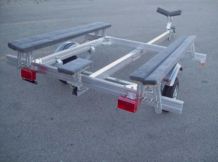
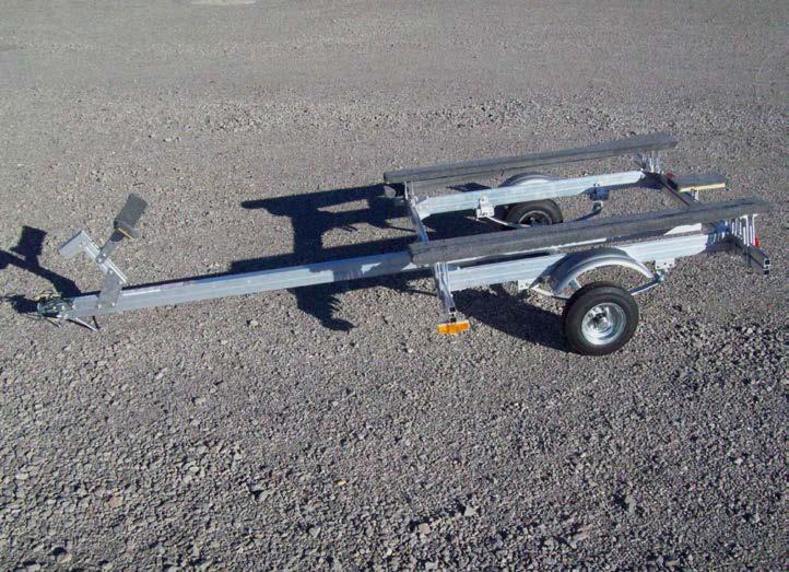
60 Finished Trailer 60

61 61 KJM 11/21/12
SUT-250-S (These instructions are used for SUT-250-SCLC also)
") SUT-250-S (These instructions are used for SUT-250-SCLC also) Torque wrench, carpenters square, wire cutters, Phillips screwdriver, 7/16, 9/16, and 3/4 combination wrenches, ratchet, 9/16, 3/4, 13/16,
SUT-250-S (These instructions are used for SUT-250-SCLC also) Torque wrench, carpenters square, wire cutters, Phillips screwdriver, 7/16, 9/16, and 3/4 combination wrenches, ratchet, 9/16, 3/4, 13/16,
UNPACK AND IDENTIFY THE FOLLOWING PARTS.
 SUT-500-S ASSEMBLY REQUIREMENTS *Torque all T-bolt nuts to 35-40 foot pounds. *Check all lights before towing. *Tire pressure not to exceed recommendation on serial tag. *Re-torque wheel nuts after first
UNPACK AND IDENTIFY THE FOLLOWING PARTS.
 SUT-350-AIT ASSEMBLY REQUIREMENTS *Torque all T-bolt nuts to 35-40 foot pounds. *Check all lights before towing. *Tire pressure not to exceed recommendation on serial tag. *Re-torque wheel nuts after first
UNPACK AND IDENTIFY THE FOLLOWING PARTS.
 SUT-250-M2 ASSEMBLY REQUIREMENTS *Torque all T-bolt nuts to 35-40 foot pounds. *Check all lights before towing. *Tire pressure not to exceed recommendation on serial tag. *Re-torque wheel nuts after first
UT ASSEMBLY REQUIREMENTS. *Torque all T-bolt nuts to foot pounds.
 UT-1000-8-04 ASSEMBLY REQUIREMENTS *Torque all T-bolt nuts to 35-40 foot pounds. *Check all lights before towing. *Tire pressure not to exceed recommendation on serial tag. *Re-torque wheel nuts after
UT ASSEMBLY REQUIREMENTS. *Torque all T-bolt nuts to foot pounds.
 UT-1200-16-04 ASSEMBLY REQUIREMENTS *Torque all T-bolt nuts to 35-40 foot pounds. *Check all lights before towing. *Tire pressure not to exceed recommendation on serial tag. *Re-torque wheel nuts after
<THESE INSTRUCTIONS MUST BE GIVEN TO THE END USER> B&W
 B&W Trailer Hitches 1216 Hawaii Rd / PO Box 186 Humboldt, KS 66748 P:620.473.3664 F:620.869.9031 Turnoverball Gooseneck Hitch Installation Instructions
PLEASE READ THIS INSTRUCTIONS CAREFULLY, BEFORE YOU START INSTALLATION
 INSTALLATION INSTRUCTIONS PART NUMBER: L0SXC000 DESCRIPTION: 09 ASCENT TRAILER HITCH PLEASE READ THIS INSTRUCTIONS CAREFULLY, BEFORE YOU START INSTALLATION SAFETY PRECAUTION: When installing Trailer Hitch,
GROSS LOAD CAPACITY WHEN USED AS A WEIGHT CARRYING HITCH: 2,000 LBS. TRAILER WEIGHT & 200 LBS. TONGUE WEIGHT.
 PAGE 1 0F 6 GROSS LOAD CAPACITY WHEN USED AS A WEIGHT CARRYING HITCH: 2,000 LBS. TRAILER WEIGHT & 200 LBS. TONGUE WEIGHT. WARNING: ALL NON-TRAILER LOADS APPLIED TO THIS PRODUCT MUST BE SUPPORTED BY 18050
<THESE INSTRUCTIONS MUST BE GIVEN TO THE END USER> B&W
 B&W Trailer Hitches 6 Hawaii Rd / PO Box 86 Humboldt, KS 66748 P:60.473664 F:60.869.903 Turnoverball Gooseneck Hitch Installation Instructions MODEL 08
At-A-Glance Trailer Assembly Overview
 At-A-Glance Trailer Assembly Overview VERY IMPORTANT; ALWAYS REFER TO YOUR OWNER S MANUAL FOR PROPER OPERATING AND SAFETY INFORMATION REGARDING YOUR TRAILER. INCASE OF LOSS GO TO WWW.UTILITYMATE.COM BEFORE
PLEASE READ THESE INSTRUCTIONS CAREFULLY, BEFORE YOU START INSTALLATION
 PART NUMBER: L0SSJ000 INSTALLATION INSTRUCTIONS DESCRIPTION: FORESTER TRAILER HITCH PLEASE READ THESE INSTRUCTIONS CAREFULLY, BEFORE YOU START INSTALLATION SAFETY PRECAUTION: When installing Trailer Hitch,
INSTALLATION INSTRUCTIONS
 INSTALLATION INSTRUCTIONS AUTOMOTIVE PRODUCTS, INC. APPLICATION: 2006-2008 FORD F-150 PART NUMBER: 45-92010, 40-92015 WINCH MOUNTED SPORTSMAN GRILLE GUARD ITEM QUANTITY ITEM DESCRIPTION TOOLS NEEDED 1
LittleGiant Trailer Harley Hauler Kit
 3380 N. El Paso St., Colorado Springs, CO 80907 LittleGiant Trailer Harley Hauler Kit User Assembly Manual Visit our website at www.letsgoaero.com For Assistance, please call 1-877-464-2376 or 719-630-3800
** DO NOT EXCEED THE RECOMMENDED VEHICLE TOWING WEIGHT RATING ** DODGE RAM 1500
 10/3/2017 DODGE RAM 1500 WARNING!! BRAKE, FUEL, AND ELECTRICAL LINES MAY NEED TO BE LOOSENED OR REPOSITIONED TO PROVIDE CLEARANCE FOR NEW HARDWARE. ON SHORT BED MODELS, CHECK FOR ADEQUATE TURNING CLEARANCE
MODEL 2604 WARNING <THESE INSTRUCTIONS MUST BE GIVEN TO THE END USER> Custom 5th Wheel Hitch Mounting Rail Installation Instructions
 B&W Trailer Hitches 1216 Hawaii Rd / PO Box 186 Humboldt, KS 66748 P:620.473.3664 F:620.869.9031 Custom 5th Wheel Hitch Mounting Rail Installation Instructions
GL1800 TRAILER HITCH - INSTALLATION INSTRUCTIONS #GL
 GL1800 TRAILER HITCH - INSTALLATION INSTRUCTIONS #GL18007-20 Read through these instructions completely before attempting installation, lay out all pieces including the numbered hardware bags to familiarize
NORTHSTAR TRAILERS. Assembly Guide for SPORTSTAR II Trailer
 NORTHSTAR TRAILERS Assembly Guide for SPORTSTAR II Trailer Congratulations! You are the proud owner of a NORTHSTAR trailer. Please follow the instructions and steps in this manual for proper assembly.
AEV30308AA Last Updated: 05/31/18. 4 DUALSPORT sc SUSPENSION system for RAM 1500 air ride standard and rebel INSTALLATION GUIDE
 AEV30308AA Last Updated: 05/31/18 4 DUALSPORT sc SUSPENSION system for RAM 1500 air ride standard and rebel INSTALLATION GUIDE PLEASE READ BEFORE YOU START TO GUARANTEE A QUALITY INSTALLATION, WE RECOMMEND
Installation Instructions
 Equipment Required: Fastener Kit: F Wrenches: 3/4, 15/16 Drill Bits: 1/4 Other Tools: Drill Installation Instructions Short & Long Bed All Megacabs 9464/9474 HIDE-A-GOOSE HITCH INSTALLATION WARNING: Under
2017 Current Ford Raptor Bump Stop Kit Installation Instructions
 2017 Current Ford Raptor Bump Stop Kit Installation Instructions PREPARATION 1. Disconnect the negative terminal on the battery. Park the vehicle on level ground and set the emergency brake. 2. We recommend
SAFETY THIS PRODUCT IS FOR OFFROAD USE ONLY. ALL LIABILITY FOR INSTALLATION AND USE RESTS WITH THE OWNER.
 SAFETY Your safety and the safety of others is very important. In order to help you make informed decisions about safety, we have provided installation instructions and other information. These instructions
INSTALLATION INSTRUCTIONS For 65800, 65801, 66355, 69250, Rear Bumper And Tire Carrier For Jeep XJ Cherokee
 INSTALLATION INSTRUCTIONS For 65800, 65801, 66355, 69250, 69251 Rear Bumper And Tire Carrier For Jeep XJ Cherokee Your safety, and the safety of others, is very important. To help you make informed decisions
INSTALLATION INSTRUCTIONS
 INSTALLATION INSTRUCTIONS Accessory HITCH Application 2012 CROSSTOUR Publications No. AII 46198 Issue Date JULY 2011 PARTS LIST Trailer Hitch Kit P/N 08L92-TP6-101 Upper spacer A (5 mm) (Some are not used.)
PDF created with pdffactory trial version
 J 4628 MH 0-5-08 H 458 MH 05-2-08 DWG. REV. ECR/NDR NUMBER REVISED BY DATE 0-02 REPLACED 0-02205 (" TIRES); 0-02 REPLACED 0-02252 (4" TIRES); 00-0900 REPLACED 00-00999 0-069 WAS 0-0228.X 0.00.XXXX 0.00-2-06
NORTHSTAR TRAILERS. Assembly Guide for SPORTSTAR I Trailer
 NORTHSTAR TRAILERS Assembly Guide for SPORTSTAR I Trailer Congratulations! You are the proud owner of a NORTHSTAR trailer. Please follow the instructions and steps in this manual for proper assembly. We
INSTALLATION INSTRUCTIONS
 INSTALLATION INSTRUCTIONS Accessory Application Publications No. 2004 S2000 AII 26323-31611 Issue Date DEC 2005 PARTS LIST Rear defroster switch Hardtop 3-Pin subharness (If equipped, not used) 4-Pin subharness
2017 Current Ford Raptor ADD Pro Rear Bumper Installation Instructions
 2017 Current Ford Raptor ADD Pro Rear Bumper Installation Instructions PREPARATION 1. Disconnect the negative terminal on the battery. Park the vehicle on level ground and set the emergency brake. 2. We
SAFETY THIS PRODUCT IS FOR OFFROAD USE ONLY. ALL LIABILITY FOR INSTALLATION AND USE RESTS WITH THE OWNER.
 SAFETY Your safety and the safety of others is very important. In order to help you make informed decisions about safety, we have provided installation instructions and other information. These instructions
Fig A. Addictive Desert Designs. Preparation: Removal:
 Preparation: Disconnect the negative battery terminal. Park the vehicle on level ground and set the emergency brake. We recommend reading through the installation instructions in whole before performing
BAG 3 (2) 2.25 x 1 Sleeves (4) 1/4 Nylock Nuts (4) 1/4 x 2 Bolts (4) 3/8 Nylock Nuts (4) 3/8 Flat Washers (2) 3/8 U-Bolts
 2.25 x 1 Sleeves (4) 1/4 Nylock Nuts (4) 1/4 x 2 Bolts (4) 3/8 Nylock Nuts (4) 3/8 Flat Washers (2) 3/8 U-Bolts") INSTALLATION INSTRUCTIONS PART # DESCRIPTION 799 Lincoln Ave. Riverside, CA 90 Phone: 9.689.ICON Fax: 9.689.06 90 00+ RAPTOR REAR BUMPSTOP SYSTEM ** READ ALL INSTRUCTIONS THOROUGHLY FROM START TO FINISH
INSTALLATION INSTRUCTIONS PART # DESCRIPTION 799 Lincoln Ave. Riverside, CA 90 Phone: 9.689.ICON Fax: 9.689.06 90 00+ RAPTOR REAR BUMPSTOP SYSTEM ** READ ALL INSTRUCTIONS THOROUGHLY FROM START TO FINISH
Fig A ADDICTIVE DESERT DESIGNS. Preparation: Removal: Release these clips
 Preparation: Disconnect the negative battery terminal. Park the vehicle on level ground and set the emergency brake. We recommend reading through the installation instructions in whole before performing
NORTHSTAR TRAILERS. Assembly Guide for MULTISTAR Trailer
 NORTHSTAR TRAILERS Assembly Guide for MULTISTAR Trailer Congratulations! You are the proud owner of a NORTHSTAR trailer. Please follow the instructions and steps in this manual for proper assembly. TRAILER
Please read thoroughly before starting installation and check that kit contents are complete.
 Rear Vision System Mirror Display 2013-Current Ram (Kit part number 1009-9518) Please read thoroughly before starting installation and check that kit contents are complete. Items Included in the Kit: Rear
SAFETY THIS PRODUCT IS FOR OFFROAD USE ONLY. ALL LIABILITY FOR INSTALLATION AND USE RESTS WITH THE OWNER.
 Installation Instructions SAFETY Your safety and the safety of others is very important. In order to help you make informed decisions about safety, we have provided installation instructions and other
B4578BTPA Fender Mounting Instructions for MIN4000, MIN900, MIN1500 & MIN1554 Fenders
 STEP 1 B4578BTPA Fender Mounting Instructions for MIN4000, MIN900, MIN1500 & MIN1554 Fenders A. Unpack all cartons and lay out parts. B. Compare the parts with hardware kit B4578BTPA as shown in Figure
INSTALLATION INSTRUCTIONS
 INSTALLATION INSTRUCTIONS [1] Description: Tow Hitch Wire Harness Kit [2] Application: Nissan Rogue Note: Tow Harness application is limited to specific vehicle option packages that include tow harness
6 S-10 Pickup/Jimmy/Blazer Torsion Bar Drop Kit
 92124300 6 S-10 Pickup/Jimmy/Blazer Torsion Bar Drop Kit Thank you for choosing Rough Country for all your suspension needs. Rough Country recommends a certified technician install this system. In addition
LEXUS RC 350/RC-F ILLUMINATED DOOR SILLS Preparation
 Preparation Part Number: PT944-24150 Kit Contents Item # Quantity Reqd. Description 1 2 Inner LED Scuff 2 2 Outer Scuff 3 1 Hardware Bag Hardware Bag Contents Item # Quantity Reqd. Description 1 15 20
INSTALLATION INSTRUCTIONS HD BUMPER AND WINCH MOUNTING KIT Part Number: 74777, Application: 08-NEWER FORD SUPER DUTY WARNING
 INSTALLATION INSTRUCTIONS HD BUMPER AND WINCH MOUNTING KIT Part Number: 74777, 76250 Application: 08-NEWER FORD SUPER DUTY Your safety, and the safety of others, is very important. To help you make informed
TOYOTA VENZA 2009 TRAILER WIRE HARNESS Procedure
 Part Number: PT791-0T099 Kit Contents Item # Quantity Reqd. Description 1 1 Trailer Wire Harness Module 2 1 4-Flat Harness 3 1 Battery Power Wire Harness 4 1 Mounting Bracket, 4-Flat 5 2 Screw #10-24 6
INSTALLATION INSTRUCTIONS DODGE DAKOTA 2 KIT # 682 (2WD), 692 (4WD) 3 KIT # 683 (2WD), 693 (4WD)
, 692 (4WD) 3 KIT # 683 (2WD), 693 (4WD)") INSTALLATION INSTRUCTIONS 1997-1999 DODGE DAKOTA 2 KIT # 682 (2WD), 692 (4WD) 3 KIT # 683 (2WD), 693 (4WD) Installation of a Performance Accessories body lift kit will change the vehicle s center of gravity
INSTALLATION INSTRUCTIONS 1997-1999 DODGE DAKOTA 2 KIT # 682 (2WD), 692 (4WD) 3 KIT # 683 (2WD), 693 (4WD) Installation of a Performance Accessories body lift kit will change the vehicle s center of gravity
TOYOTA FJ CRUISER 6 SUSPENSION KIT
 92177000 TOYOTA FJ CRUISER 6 SUSPENSION KIT Thank you for choosing Rough Country for your suspension needs. Rough Country recommends a certified technician installs this system. In addition to these instructions,
INSTALLATION INSTRUCTIONS HD BUMPER AND WINCH MOUNTING KIT Part Number: 70650, 70651, Application: 05-NEWER FORD SUPER DUTY WARNING
 INSTALLATION INSTRUCTIONS HD BUMPER AND WINCH MOUNTING KIT Part Number: 70650, 70651, 73990 Application: 05-NEWER FORD SUPER DUTY Your safety, and the safety of others, is very important. To help you make
INSTALLATION INSTRUCTION 88581
 INSTALLATION INSTRUCTION 88581 FOR RANCHO SUSPENSION SYSTEM RS6581B: DODGE RAM READ ALL INSTRUCTIONS THOROUGHLY FROM START TO FINISH BEFORE BEGINNING INSTALLATION Rev C IMPORTANT NOTES! WARNING: This suspension
INSTALLATION INSTRUCTIONS 97 FORD EXPEDITION
 INSTALLATION INSTRUCTIONS 97 FORD EXPEDITION 1. Read the instructions completely and carefully before you begin. Check the kit for proper contents (refer to the part s list and the picture diagrams). Before
TOYOTA VENZA 2009 TRAILER WIRE HARNESS Procedure
 Part Number: PT791-0T099 Kit Contents Item # Quantity Reqd. Description 1 1 Trailer Wire Harness Module 2 1 4-Flat Harness 3 1 Battery Power Wire Harness 4 1 Mounting Bracket, 4-Flat 5 2 Screw #10-24 6
2015 Ford F150 Rear Bumper w/ LED
 2015 Ford F150 Bumper w/ LED T527990 T527991 PARTS LIST: 1 Bumper Assembly 4 12mm Lock Washers 2 Mounting Brackets 6 12 mm Nylon Lock Nuts 4 Sensor Hole Plugs 8 4mm x 10mm Button Head Bolts 2 Plastic Plugs
Installation Notes: #86000-R Race Series +3.5 L/T Kit
 159 North Maple St. Unit J, CORONA CA 92880 P. 951-737-9682 F. 951-737-9006 WWW.CHAOSFAB.COM Installation Notes: #86000-R Race Series +3.5 L/T Kit Factory manual is recommended for removal and re-installation
VELAR HITCH INSTALLATION INSTRUCTIONS TOW RANGE ROVER MODEL/ TRIM YEARS: WEIGHT CAPACITY to Present PARTS & SUPPLIES: TOOLS REQUIRES:
 HITCH INSTALLATION INSTRUCTIONS MAKE: RANGE ROVER YEARS: 2018 to Present MODEL/ TRIM VELAR PACKAGE: TOW WEIGHT CAPACITY TRAILER TONGUE 5300 LBS. 300 LBS. INSTALLATION TIME: 2 HOURS NO YES YES PARTS & SUPPLIES:
09-12 Dodge 4WD /4 Body Lift
 92RC80000 09-12 Dodge 4WD 1500 1 1/4 Body Lift Thank you for choosing Rough Country for all your suspension needs. Rough Country recommends a certified technician install this kit. Attempts to install
SAFETY THIS PRODUCT IS FOR OFFROAD USE ONLY. ALL LIABILITY FOR INSTALLATION AND USE RESTS WITH THE OWNER.
 SAFETY Your safety and the safety of others is very important. In order to help you make informed decisions about safety, we have provided installation instructions and other information. These instructions
<THESE INSTRUCTIONS MUST BE GIVEN TO THE END USER> B&W Trailer Hitches 1216 Hawaii Rd / PO Box 186 Humboldt, KS P: F:
 B&W Trailer Hitches 6 Hawaii Rd / PO Box 86 Humboldt, KS 6678 P:60.7366 F:60.73766 Turnoverball Gooseneck Hitch Installation Instructions MODEL 38 0 06
INSTALLATION INSTRUCTIONS SEMI-HIDDEN WINCH MOUNT Part Number:70005 Application: Ford Super Duty
 INSTALLATION INSTRUCTIONS SEMI-HIDDEN WINCH MOUNT Part Number:70005 Application: Ford Super Duty Your safety, and the safety of others, is very important. To help you make informed decisions about safety,
INSTALLATION INSTRUCTIONS
 INSTALLATION INSTRUCTIONS Accessory Application 2011 RDX Publications No. BII 43544 Issue Date JULY 2010 PARTS LIST 2 Bolts, 12 x 40 mm Trailer Hitch Kit P/N 08L92-STK-200A Trailer hitch Hitch pin Hitch
INSTALLATION INSTRUCTIONS
 INSTALLATION INSTRUCTIONS Models: 7105 & 7105TK Dodge Ram 1500 ('02 Current) Ram 2500 & 3500 '03 - Current with stock manual mirrors. IF YOU DO NOT CURRENTLY HAVE MANUAL MIRRORS, THE WRONG SET HAS BEEN
INSTALLATION GUIDE PREMIUM FRONT BUMPER FOR RAM AEV30304AA Last Updated: 09/18/17
 AEV30304AA Last Updated: 09/18/17 PREMIUM FRONT BUMPER FOR RAM 1500 INSTALLATION GUIDE PLEASE READ BEFORE YOU START To guarantee a quality installation, we recommend reading these instructions thoroughly
INFINITY MULTA SERIES
 ASSEMBLY ASSEMBLY INSTRUCTIONS INSTRUCTIONS ASSEMBLY INSTRUCTIONS INFINITY MULTA SERIES Workstations, WORKSTATIONS, desks, DESKS, and AND tables TABLES with WITH powered POWERED ADJUSTMENT adjustment PARTS
TOYOTA COROLLA LOWERING SPRINGS Preparation
 Preparation Part Number: PTR07-02140 Kit Contents Item # Quantity Reqd. Description 1 2 Front Spring 2 2 Rear Spring 3 1 Hardware 4 1 Instruction Form Hardware Bag Contents Item # Quantity Reqd. Description
INSTALLATION INSTRUCTIONS
 INSTALLATION INSTRUCTIONS Accessory Application Publications No. AII 25877 PILOT Issue Date AUG 2003 Optional ATF and power steering coolers are required when installing the trailer hitch. 2 Spacers PARTS
INSTALLATION & OWNER S MANUAL
 Rev. C p. 1 of 21 INSTALLATION & OWNER S MANUAL F5205 HARD SIDED CAB KIT INSTALLATION & OWNER S MANUAL The contents of this envelope are the property of the owner. Be sure to leave with the owner when
INSTALLATION INSTRUCTIONS
 Accessory Application Publication No. INSTALLATION INSTRUCTIONS WINCH MOUNT KIT P/N 08L77-HL3-A00 SXS700M4/M2 Honda Dealer: Please give a copy of these instructions to your customer. MII 14607 Issue Date
»Product» Safety Warning
 C1351 Installation Instructions 2014 Chevy/GMC, ½ Ton, 2/4wd 3.5" Combo Kit Read and understand all instructions and warnings prior to installation of product and operation of vehicle. Zone Offroad Products
TITAN Fuel Tanks. INSTALLATION INSTRUCTIONS G e n e r a t i o n V. Extended Capacity Replacement Tank for Diesel Chevrolet / GMC Trucks
 Important: Please read these instructions carefully and completely before starting the installation. TITAN Fuel Tanks INSTALLATION INSTRUCTIONS G e n e r a t i o n V Extended Capacity Replacement Tank
INSTALLATION INSTRUCTIONS
 INSTALLATION INSTRUCTIONS Accessory Application 2010 RDX Publications No. BII 41807 Issue Date JULY 2009 PARTS LIST 2 Bolts, 12 x 40 mm Trailer Hitch Kit P/N 08L92-STK-200A Trailer hitch Hitch pin Ball
Fig A ADDICTIVE DESERT DESIGNS. Preparation: Removal:
 Preparation: Disconnect the negative battery terminal. Park the vehicle on level ground and set the emergency brake. We recommend reading through the installation instructions in whole before performing
<THESE INSTRUCTIONS MUST BE GIVEN TO THE END USER> B&W
 B&W Trailer Hitches 6 Hawaii Rd / PO Box 86 Humboldt, KS 6678 P:60.7366 F:60.86.03 Turnoverball Gooseneck Hitch Installation Instructions MODEL 38 0 08
LIFT-507 BMF Lift Kit E-Z-Go RXV Gas or Electric Installation Instructions
 LIFT-507 BMF Lift Kit E-Z-Go RXV Gas or Electric Installation Instructions Contents of LIFT-507 E-Z-Go RXV BMF Lift Kit: a (1 ea.) BMF A-Arm Assembly b (1 ea.) Driver Side Shock Tower c (1 ea.) Passenger
INSTALLATION INSTRUCTIONS
 INSTALLATION INSTRUCTIONS Accessory Application Publications No. S 1998 CIVIC 2/3/4-DOOR All 18767 Issue Date SEP 1997 PARTS LIST Fog Light Kit: P/N 08V31-S01-100 Right fog light (marked R ) Fuse label
ST - HD - HDXL Model
 ST - HD - HDXL Model TOOLS REQUIRED FOR ASSEMBLY OF THE TANDEM TOW DOLLY Ratchet Socket Wrench with sockets sizes: 7/16, 9/16, 3/ 4 & 15/16 7/16 Box or Open End Wrench 9/16 Box or Open End Wrench 3/4 Box
07-11 GM 4WD 1500 P/U 1 1/4 Body Lift
 92RC70100 07-11 GM 4WD 1500 P/U 1 1/4 Body Lift Thank you for choosing Rough Country for all your suspension needs. Rough Country recommends a certified technician install this kit. Attempts to install
2014 GM 1500 TRUCK STOP---READ THIS FIRST! 7" Lift KIT. **Read These Entire Instructions Before Starting Anything**
 STOP---READ THIS FIRST! **Read These Entire Instructions Before Starting Anything** 2014 GM 1500 TRUCK LIFT KIT INSTRUCTIONS (PART #50768 & #50769 ) 5680 W. Barstow, Fresno, CA 93722 PH: (559) 226-8196
INSTALLATION INSTRUCTIONS
 PART NO. 23100T PRODUCT DESCRIPTION: Front Winch Bumper, Center Section PRODUCT SAFETY & LEGAL DISCLAIMER IMPORTANT READ ALL INSTRUCTIONS CAREFULLY BEFORE INSTALLING, FAILURE TO DO SO MAY CAUSE PERSONAL
GOMINIGO Third Brake Light Pulsar Kit. Installation Instructions
 Page 1 of 8 Mini Cooper Installation Instructions This kit allows the owner of any MINI Cooper or Cooper S to create a blinking effect from the third brake light assembly. The MINI Cooper being hit from
LPE C5 Battery Relocation Kit
 LPE C5 Battery Relocation Kit The LPE C5 Corvette battery relocation kit improves vehicle weight distribution by moving weight to the rear of the vehicle. The improved weight distribution increases traction
STOP---READ THIS FIRST!
 STOP---READ THIS FIRST! **Read These Entire Instructions Before Starting Anything** 2007-2010 GM 1500 TRUCK LIFT KIT INSTRUCTIONS (PART# 50700 & 50720) 5680 W. Barstow, Fresno, CA 93722 PH: (559) 226-8196
R O A D S M I T H TRIKE CONVERSIONS BY THE TRIKE SHOP
 R O A D S M I T H TRIKE CONVERSIONS BY THE TRIKE SHOP Please thoroughly review the instructions before and during installation. Keep in mind that this product was designed to be installed by trained dealer
INSTALLATION INSTRUCTIONS LD-1 REAR BUMPER RAM 1500 PART#R R #PW017838
 INSTALLATION INSTRUCTIONS LD-1 REAR BUMPER PART#R102617 R102620 #PW017838 PARTS LIST: 1 LD1 Bumper Assembly 4 12-1.75mm x 40mm Hex Bolts 1 Push in License Plate Light 4 12mm x 37mm x 3mm Flat Washers 2
INSTALLATION INSTRUCTIONS
 INSTALLATION INSTRUCTIONS Accessory Application Publications No. SYSTEM 2005 ACCORD All 27511 (DX, LX) 2-AND 4-DOOR Issue Date AUG 2004 PARTS LIST Security System Attachment (LX): P/N 08E55-SDA-100A Unit
2014 Current Chevy/GMC 1500 HoneyBadger Rear Bumper Installation Instructions
 2014 Current Chevy/GMC 1500 HoneyBadger Rear Bumper Installation Instructions PREPARATION 1. Disconnect the negative terminal on the battery. Park the vehicle on level ground and set the emergency brake.
ROUSH Active IO Exhaust. Installation Instructions P/N: (R LITE) Fastback GT Convertible GT V8
 Fastback GT Convertible GT V8") Installation Instructions P/N: 422128 (R1318-5231LITE) Fastback GT Convertible GT V8 39555 Schoolcraft Rd, Plymouth MI, 48170 800.59.ROUSH ROUSH Active IO Exhaust Installation Instructions P/N: 422128
Installation Instructions P/N: 422128 (R1318-5231LITE) Fastback GT Convertible GT V8 39555 Schoolcraft Rd, Plymouth MI, 48170 800.59.ROUSH ROUSH Active IO Exhaust Installation Instructions P/N: 422128
LIFT-304 (3 ) and LIFT-104 (6 ) Drop Spindle Lift Kits Yamaha G22, Gas or Electric Installation Instructions
 and LIFT-104 (6 ) Drop Spindle Lift Kits Yamaha G22, Gas or Electric Installation Instructions") LIFT-304 (3 ) and LIFT-104 (6 ) Drop Spindle Lift Kits Yamaha G22, Gas or Electric Installation Instructions LIFT-304 LIFT-104 Contents of LIFT-304/104 Yamaha G22 Lift Kit: a (1 ea.) Passenger Side Spindle
LIFT-304 (3 ) and LIFT-104 (6 ) Drop Spindle Lift Kits Yamaha G22, Gas or Electric Installation Instructions LIFT-304 LIFT-104 Contents of LIFT-304/104 Yamaha G22 Lift Kit: a (1 ea.) Passenger Side Spindle
INSTALLATION INSTRUCTIONS FORD F-150 2WD & 4WD RETAINS FACTORY TOW HOOKS PART #P3063
 INSTALLATION INSTRUCTIONS FORD F-150 2WD & 4WD RETAINS FACTORY TOW HOOKS PART #P3063 PARTS LIST: 1 Grille Guard 2 10-1.5mm Nylon Lock Nuts 1 Driver/Left Frame Mounting Bracket 4 12mm Plastic Washers 1
LIFT Drop Spindle Lift Kit E-Z-Go RXV Gas or Electric Installation Instructions
 LIFT-107 6 Drop Spindle Lift Kit E-Z-Go RXV Gas or Electric Installation Instructions Contents of LIFT-107 E-Z-Go RXV Drop Spindle Lift Kit: a (1 ea.) Driver Side Spindle b (1 ea.) Passenger Side Spindle
Page1. ISF Stainless Steel Headers // Part# HDR-004
 Congratulations on the purchase of your ISF Stainless Steel Headers and thank you for choosing Sikky Manufacturing. This installation manual is intended to guide you through the removal of the factory
INSTALLATION INSTRUCTIONS
 AUTOMOTIVE PRODUCTS, INSTALLATION INSTRUCTIONS ULTIMATE BULL BAR APPLICATION: 2009-2018 Dodge Ram 1500 (Excl. Rebel Model) 2019 Dodge Ram 1500 Classic PART NUMBER: 32-1960, 32-1965, 32-1960L, 32-1965L
STOP---READ THIS FIRST!
 STOP---READ THIS FIRST! **Read These Entire Instructions Before Starting Anything** 2007-2013 GM 1500 TRUCK LIFT KIT INSTRUCTIONS (PART# 50700 & 50720) 5680 W. Barstow, Fresno, CA 93722 PH: (559) 226-8196
2017 Current Ford Raptor HoneyBadger Rear Bumper Installation Instructions
 2017 Current Ford Raptor HoneyBadger Rear Bumper Installation Instructions PREPARATION 1. Disconnect the negative terminal on the battery. Park the vehicle on level ground and set the emergency brake.
<THESE INSTRUCTIONS MUST BE GIVEN TO THE END USER> B&W
 B&W Trailer Hitches 1216 Hawaii Rd / PO Box 186 Humboldt, KS 66748 Turnoverball Gooseneck Hitch Installation Instructions MODEL 1314 2013 2014 RAM 3500
TESLA MODEL S REAR UNDER SPOILER & DIFFUSER SYSTEM
 TESLA MODEL S Thank you for purchasing your Unplugged Performance Rear Under Spoiler & Diffuser System for the Tesla Model S! Please read this manual carefully prior to installation. REAR UNDER SPOILER
LEXUS GX TOWING HITCH Preparation
 LEXUS GX460 2014 - TOWING HITCH Preparation Part Number: PT228-60140 Kit Contents Item # Quantity Reqd. Description 1 1 Hitch Assembly 2 1 Wiring Harness Bracket 3 1 Hardware Bag 4 1 Hitch Cover 5 2 Center
07-11 GM 1500 Pickup, Avalanche, Yukon, Tahoe, Suburban Front 2.5 Kit
 92130500 07-11 GM 1500 Pickup, Avalanche, Yukon, Tahoe, Suburban Front 2.5 Kit Thank you for choosing Rough Country for all your suspension needs. Rough Country recommends a certified technician install
READ AND UNDERSTAND ALL INSTRUCTIONS AND WARNINGS PRIOR TO INSTALLATION OF SYSTEM AND OPERATION OF VEHICLE.
 #9378 Installation Instructions 3 Body Lift Kit 1998-2000 Ranger READ AND UNDERSTAND ALL INSTRUCTIONS AND WARNINGS PRIOR TO INSTALLATION OF SYSTEM AND OPERATION OF VEHICLE. SAFETY WARNING BDS Suspension
INSTALLATION INSTRUCTIONS
 INSTALLATION INSTRUCTIONS Accessory Application Publication No. WINCH MOUNT P/N 08L74-HR3-A20 After 13 TRX420 (All except TRX420FA/FPA) After 13 TRX500 (All except TRX500FA/FPA) MII 15067 Issue Date Revised:
INSTALLATION INSTRUCTIONS ELITE FRONT BUMPER Part Number: w/ Grille Guard & w/o Grille Guard Application: Jeep JK 2007+
 INSTALLATION INSTRUCTIONS ELITE FRONT BUMPER Part Number: 87750 w/ Grille Guard & 87775 w/o Grille Guard Application: Jeep JK 2007+ GENERAL SAFETY PRECAUTIONS Your safety, and the safety of others, is
Trailer Parts. Brake Components. Axle Components. Suspensions. Lights & Electrical. Wheels & Tires. Loading Ramps. Couplers & Safety Chains
 Trailer Parts Brake Components Axle Components Suspensions Lights & Electrical Wheels & Tires Loading Ramps Couplers & Safety Chains Trailer Jacks Fenders Dump Trailer Parts Tilt SST Parts Decal Kits Brake
INSTALLATION & OWNER S MANUAL
 INSTALLATION & OWNER S MANUAL CAB INSTALLATION INSTRUCTIONS JOHN DEERE GATOR HPX and/or XUV HARD SIDED CAB ENCLOSURE (p/n: 1GTR44AS) SOFT SIDED CAB ENCLOSURE (p/n: 1GTR44SS) 111 HIGGINS STREET, WORCESTER,
PARTS LIST INSTALLATION INSTRUCTIONS PARTS LIST AND INSTALLATION GUIDE INSTALL TIME: 2 HOURS INSTALL DIFFICULTY: 3/5
 PARTS LIST AND PARTS LIST 1PC MISHIMOTO INTERCOOLER 1PC M6 X 1.0 X 20MM FLANGE BOLT 1PC M4 X 0.7 X 12MM BUTTON-HEAD BOLT 1PC M4 LOCK WASHER 1PC MAP SENSOR O-RING 2. Remove the eight pop clips that hold
INSTALLATION INSTRUCTIONS
 INSTALLATION INSTRUCTIONS Accessory Application Publications No. AII 30518 KIT 2006 PILOT Issue Date NOV 2005 NOTE: Accessory ATF and power steering coolers are required when installing the trailer hitch.
INSTALLATION INSTRUCTIONS. Rear Vision System Aftermarket Display 2009-Current Dodge Ram (Kit part number )
") Rear Vision System Aftermarket Display 2009-Current Dodge Ram (Kit part number 1009-6503) Kit Contents: Chassis Harness with RCA (Note: In some cases a RCA extension may be required to connect to your
Rear Vision System Aftermarket Display 2009-Current Dodge Ram (Kit part number 1009-6503) Kit Contents: Chassis Harness with RCA (Note: In some cases a RCA extension may be required to connect to your