E-118 NEXT : ASSEMBLY GUIDE
|
|
|
- Richard Melton
- 6 years ago
- Views:
Transcription

1 E-118 NEXT : ASSEMBLY GUIDE Revision
2 E-118 NEXT : Table of contents Assembly overview Frame inspection Fork installation Handlebar installation Handlebar assembly For the warranty to be valid, the bicycle must be fully assembled by an authorized Argon 18 dealer. High end components, particularly carbon parts, need extra care when assembled. Those components must be installed using a calibrated torque wrench to make sure every bolt is at the right torque setting to prevent damage. 5. Cable housing installation Electronic drive-train specification Front brake installation Rear brake installation Armrest assembly Seatpost installation Saddle adjustment Derailleur hanger adjustment Parts listing


3 E-118 NEXT : Assembly overview 1. Frame inspection 2. Fork installation 3. Handlebar installation 4. Handlebar assembly 5. Cable housing installation IMPORTANT NOTICE: It is easier to install the cables and cable housings before the bearings. 6. Electronic drive-train specification 2


4 E-118 NEXT : Assembly overview 7. Front brake installation 8. Rear brake installation 9. Armrest assembly 10. Seatpost installation 11. Saddle adjustment 12. Derailleur hanger adjustment 3


5 E-118 NEXT : Assembly overview 13. Parts listing 4
6 E-118 NEXT : 1. Frame inspection When assembling a new frame, be sure to check if the following parts are assembled correctly. Parts installed on the frame Description Screw Torque Detail type Nm 1 Front derailleur hanger Screw (2) 3mm 4Nm Loctite 2 Rear derailleur hanger Screw (2) 3mm 4Nm Loctite 3 Bottle cage Screw (4) 4mm 3Nm Grease 4 Bottom bracket cover Screw (2) 5mm 2Nm Grease 5
 and 26 MR122 (1 1/8 ) inside")

7 E-118 NEXT : 2. Fork installation Install bearings 27 MR136 (1 ¼ ) and 26 MR122 (1 1/8 ) inside the frame after greasing the surfaces. 2.2 Install the fork by placing the lower part first, and then balancing the upper part in its final position. 26 6
 located on the fork. 2.")

8 E-118 NEXT : 2. Fork installation 2.3 Slightly unscrew the steering column set screw (4c) located on the fork. 2.4 Screw in the compression column (4b) (specific to the size of your frame) inside the head tube. The threads must be lightly greased until the compression column can be inserted smoothly and tightly. 4b 2.5 Screw in the safety screw (4c) at 6Nm. 4c 6Nm 7
 or low (- 2.5cm). 3.")
9 E-118 NEXT : 3. Handlebar installation 3.1 Choose the desired position of the handlebar: high (+ 2.5cm) or low (- 2.5cm). 3.2 Apply grease on the 4 screws (6) (M6x22mm) and tighten them at 6Nm in an alternate way. 6Nm 6 8
 and two sleeve nuts (15).")
10 E-118 NEXT : 3. Handlebar installation (continued) 3.3 Install vertical spacers (17) and two sleeve nuts (15). 5Nm 5Nm 5Nm 5Nm See next page for stack configuration options. CARBON FIBER ASSEMBLY COMPOSITE
11 E-118 NEXT : 3. Handlebar installation (continued) Parts needed to adjust pads stack's height Total stack height (mm) WITH SWIVEL Required spacer X X X X None 5 10 Sleeve nut 20mm 20mm 30mm Screw (flat head) 15mm 15mm 15mm WITHOUT SWIVEL Required spacer None Sleeve nut 20mm 20mm 30mm 30mm 30mm 30mm 50mm Screw (flat head) 15mm 15mm 15mm 15mm 25mm 25mm 15mm Total stack height (mm) WITH SWIVEL Required spacer Sleeve nut 30mm 30mm 30mm 50mm 50mm 50mm 50mm Screw (flat head) 15mm 25mm 25mm 15mm 15mm 25mm 25mm WITHOUT SWIVEL Required spacer Sleeve nut 50mm 50mm 50mm 50mm 50mm 80mm 80mm Screw (flat head) 15mm 25mm 25mm 35mm 35mm 15mm 15mm Total stack height (mm) WITH SWIVEL Required spacer Sleeve nut 50mm 50mm 80mm 80mm 80mm 80mm 80mm Screw (flat head) 35mm 35mm 15mm 15mm 25mm 25mm 35mm WITHOUT SWIVEL Required spacer Sleeve nut 80mm 80mm 80mm 80mm 80mm 80mm 80mm Screw (flat head) 25mm 25mm 35mm 35mm 45mm 45mm 55mm Notes: - Always place the smaller spacers underneath - Make sure you have at least 6 full threads on each screw - Every spacer screw must be tightened to 5Nm - The M6 screw (5mm allen key) that enables the swivel adjustment must be tightened to 8Nm - The screws linking the extension connectors to the swivel are 12mm long (M5 flat head) 10
 2- Swivel spacer (14a + 14b) 3- Swivel screw (14c) 5Nm CARBON FIBER ASSEMBLY COMPOSITE")

 to 8Nm.")
12 E-118 NEXT : 3. Handlebar installation (continued) 5Nm 5Nm 5Nm 5Nm 3.4 For an inclined position, use the swivel assembly (14). STEP 1 : Swivel assembly content: 1- Connector base (8) 2- Swivel spacer (14a + 14b) 3- Swivel screw (14c) 5Nm CARBON FIBER ASSEMBLY COMPOSITE 4- Swivel square nut (14e) Assemble the unit and leave it unscrewed, just enough to allow adjustement and also allow to turn the swivel 90 degrees to have access to the bottom hole to fix the flat head screw at 6Nm. Once the proper angle is set, use a marker to obtain a reference and ajust both spacers with same angle. Use the Di2 hole as a starting point. Fix the 6mm flat head of the swivel screw (silver) to 8Nm. 3 6Nm 8Nm LOCTITE 1 2 STEP 2 : The connector base must be fixed to the top of the swivel assembly, not on the sleeve nuts. The sleeve nuts will be used to fix the spacers later. 4 11
 Note: Internal Di2 cabling Make sure the Di2 cables come out from the end of the")

13 E-118 NEXT : 3. Handlebar installation (continued) Note: Internal Di2 cabling Make sure the Di2 cables come out from the end of the extension bar, then insert them through the notches at the center of the spacers. Make sure the D12 cable goes through the bottom notch. Drop the cable in the handlebar using the hole between the two sleeve nuts. Run the cable inside the handlebar until it comes out of the large hole at the center. Then, connect it to the SM-EW90B junction box. 12

14 E-118 NEXT : 4. Handlebar assembly 4.1 Cut the extension bars (7) at the desired length to obtain a straight post*. The bars must no exceed 285mm in lenght. The cut must be made on the elbow side. The other end of the bar is used exclusively to install the shifter. Apply some carbon fiber assembly gel in the clamping area. *Warning: If using a ski bent section, no more than 40mm can be cut out. max cut 40mm max 285mm 13

 over the extension bars.")


15 E-118 NEXT : 4. Handlebar assembly (continued) 5Nm Insert the ski bent extension bars or straight bars inside the connectors (8) and place the extension connector bridge (9) over the extension bars. Tighten the screws (13) at 5Nm. The connector bridge can be installed in two distinct positions: long or short cockpit (9). Note: Cyclometer support 9 Install the cyclometer support between the extension bars with the plastic fasteners provided. 8 14
16 E-118 NEXT : 5. Cable housing installation Install the rear derailleur cable housing starting at the drive side s drop-out. Suggested lengths of the cable housing* (the medium frame is used as a reference) Cable housing/length XS S M L 5.2 Install the front derailleur cable housing starting under the bottom bracket shell. 5.3 Install the front brake cable housing starting at the center of the handlebar. Make sure that the cable housing does not go through the compression column, but through the space in front of the compression column (see image A, page 16). 5.4 Install the rear brake cable housing starting under the bottom bracket shell. See the table below for the cable housing length suggested. FRONT brakes (KEB leftover) 40cm 41cm 43cm 45.5cm REAR brakes (Gray EZ-Bend housing) FRONT derailleur 106.5cm 140cm 108cm 142cm 110cm 144cm 112.5cm 150cm REAR derailleur 198cm 200cm 202cm 204cm * For guidance purposes only. Can vary according to the shifters used. 15
 Note: To make the brake cable housing go")
 using one")


17 E-118 NEXT : 5. Cable housing installation (continued) Note: To make the brake cable housing go inside the handlebar more easily, use a brake cable as a guide and insert it head first (from the middle of the handlebar towards the brake lever) using one of the two side holes. Follow the curves of the handlebar. Once the cable is out, slide the cable housing along. IMPORTANT : You must cut the metal ferrule located at the end of the rear brake EZ-Bend cable housing prior to install it correctly on the rear brake barrel adjuster. A B C EZ-Bend EZ-Bend 1. 5Nm Mechanical drive-train configuration Electronic drive-train configuration 16

18 E-118 NEXT : 6. Electronic drive-train specification The Di2 cable routing can be achieve easily using this simple trick: use a brake cable and a metal cable end to fix the Di2 cable. For more information on Shimano Di2 electronic system installation, go to : 17


19 E-118 NEXT : 6. Electronic drive-train specification 19c 19d Use the proper grommet on the top tube to fix the cable correctly (depending if you use electronic shifting or mechanical drive train). 18


.")
20 E-118 NEXT : 6. Electronic drive-train specification 30 The Di2 battery can go either under the left chainstay (Shimano SM-BTR1) or inside the seatpost (Shimano SM-BTR2) by using the Di2 battery older (30). For this configuration, apply a slight amount of grease on both parts. 19


21 E-118 NEXT : 6. Electronic drive-train specification 19b 19a Use the proper grommet for the front derailleur cable depending if you use mechanical (19b) or electronic drive train (19a). 20

 in the middle hole of the fork If more tension is required, use the outer hole. 7.")
22 E-118 NEXT : 7. Front brake installation *The short end of the spring should be positioned in the notch of the spring tensionner. 25a 25c 25d 25e Install the brakes as shown in the diagram. 7.1 Install the spring* (25d) in the middle hole of the fork If more tension is required, use the outer hole. 7.2 It is important not to mix the springs of the front and rear brakes. 25j 25i 25h 7.3 Respect the colour code: the spring must be installed on the pivot of the same colour. 25b 8Nm 8Nm 21


23 E-118 NEXT : 7. Front brake installation (continued) 7.4 Adjust brake pads according to the width of your rims: To install the cable/cable housing inside the head tube, the cable and cable housing must go through the front part of the frame Pass the cable through the curved straw and then in the appropriate guide. Make sure that the length of the cable housing is sufficient for the guide to remain horizontal. 4Nm Fix the cable to the caliper with the 3mm screw and tighten it to 4Nm. 22

 24mm (ex.")
24 E-118 NEXT : 7. Brake pad spacing 25g 25f Adjust brake pads according to the width of your rims: - You can configure the brake pad spacing with 1mm (25f), 2mm (25g) or no spacers behind the brake pads depending of the rim width you are using. Spacers required according to the rim width Rim width 19mm (ex.: Shimano C50) 24mm (ex.: 808 clincher/enve) Spacer combinaison 2mm spacer 1mm spacer 26 to 27mm max NO spacer (ex.: 808 TU/303 TU) 23
 in the middle hole of the frame. To get more tension, use the outer hole.")
 and adjust the set screw (24k) after the wheel is put in place to avoid any contact between the brake arm stopper and the crankset.")
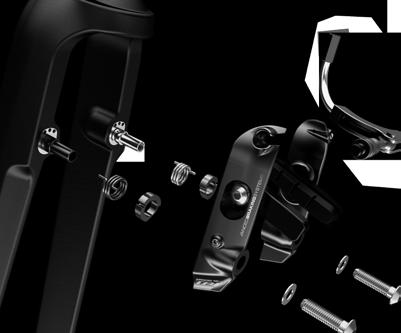
25 E-118 NEXT : 8. Rear brake installation outer side 2i 8.1 Remove the brake arm stopper (2i). 8.2 Install the brakes* as shown in the diagram. 2j+2k 24b 7Nm 24j 24d 24a 24k - Install the spring (24d) in the middle hole of the frame. To get more tension, use the outer hole. *Please note that it is easier to install the drive side brake arm if you do it before installing the crankset. 8.3 Install the brake arm stopper (2i) and adjust the set screw (24k) after the wheel is put in place to avoid any contact between the brake arm stopper and the crankset. - It is important not to mix the springs of the front and rear brakes. 7Nm 24i - Respect the colour code: the spring must be installed on the pivot of the same colour. The short end of the spring must be positioned in the notch of the spring tensionner 24c 8Nm 24h 8Nm 24
 2e Finalize the installation of the brake by screwing in the")

26 E-118 NEXT : 8. Rear brake installation (continued) 2e Finalize the installation of the brake by screwing in the cover of the plastic cable guide (2e) as shown in the diagram. Apply gentle pressure on the cover and tighten the three screws in to 2Nm, keeping the middle screw for last. - A hex key supplied with the frame makes adjusting the brake pads easier when the crankset is in place. 2Nm 2Nm 25
. 26")
27 E-118 NEXT : 9. Armrest assembly 22 4Nm Install the adhesive Velcro on the armrests (10&11). 9.2 Screw the armrests (10&11) into the extension bar connector bridge (13) at 5Nm in the position desired. Reverse the left and the right armrests to obtain a more forward or backward setup. 9.3 Finish the assembly by installing the armrest pads (22). 26
. 10.")
 on which some carbon fiber assembly gel has been applied). 10.")
28 E-118 NEXT : 10. Seatpost installation 20 3a CARBON FIBER ASSEMBLY COMPOSITE 10.1 Peel off the plastic of the doublesided tape located at the back of the seat clamp thread (3b) Place the seat clamp thread (3b) inside the frame Insert the seatpost (20) on which some carbon fiber assembly gel has been applied) Position the seatpost to the desired height and insert the seat clamp wedge (3a) Tighten the set screw to 10Nm maximum. 3b Max 10Nm 27
 by keeping a space of 2 to 3 mm between the aluminum and carbon parts. 11.")
29 E-118 NEXT : 11. Saddle adjustment 8Nm 20d 11.1 Install the saddle on the rocker (20f) and slightly tighten the rail clamp using a ball end hex key. 2-3mm 20a 20e 20c 6Nm 20f 20b 8Nm 11.2 Tighten the upper screw of the rocker clamp (20a) by keeping a space of 2 to 3 mm between the aluminum and carbon parts Adjust the angle of the saddle and tighten the lower screw of the rocker clamp (20b) Adjust the saddle offset and finish tightening of the rail clamp (20c)


.")

.")
30 E-118 NEXT : 11. Saddle adjustment 20d 20f 20d 20f The 2waypost ASP-7500 can be flipped to achieve a triathlon or a road position (75 /78 ). The seat clamp offset can be set by flipping the rail clamp (20d) and the rocker (20f). Road : -10mm to -15mm Tri : +10mm to 15mm 29


31 E-118 NEXT : 12. Derailleur hanger adjustment The front derailleur hanger can be adjusted according to the front derailleur angle to get an equal curve between the derailleur and the big chain ring. Once at the right angle, use blue 242 Loctite and screw in at 6Nm. 6Nm LOCTITE 2b LOCTITE 30


32 E-118 NEXT : 13. Parts listing 2a 2b 2c 2d 2e 2f 2g 2h 2i 2j 2k 3a 4a 4b 3b c 4d 14d 14a 14b 20a 20e 20f 16a b 14c 14e 17a 17b 20d 20c 16 16c 20b 17 17d 17c 16d 16e 17e f 9 16g h 19a 19b 19c 19d a 15b 15c 15d h 25i 25j 25d 24h 24i 24j 24d 25c 24c 25f 25g 25e 24f 24g 24e 25b 24b 25a 24a front 25 rear Brake cable / housing kit 33 Derailleur cable / housing kit JB527AR02 JD527AR02 24k Images are for reference only. Proportions are not accurate. 31
33 E-118 NEXT : 13. Parts listing No. Name A18 SKU# Qty # Frameset Parts 1 E-118 frame 1 # Parts installed on the frame 2a Rear derailleur hanger and drop out insert with screws M4x7mmF set 2b Front derailleur hanger with screws M5x16mmB & M5x16mmF - Model D c Rear axel adjustment round head Phillips screws M3x20mm and springs 2 2d Screws for water bottle cage M5x16mmB e Plastic BB cap with screws M5x20mmB and M5x16mmS f Di2 battery mount screw M4x16mmS g Font brake pivot (left; black) 1 black (right; silver) 1 silver 2h Rear brake pivot (left; black) 1 black 2i (right; silver) 1 silver Brake arm stopper round head Phillips screw M3x20mm + Aluminium sleeve 1 2j Base of FD cable guide k FD cable guide with rivets # Seat clamp kit 3a Seat clamp wedge b Seat clamp thread with screw M8x10mm
34 E-118 NEXT : 13. Parts listing No. Name A18 SKU# Qty # Fork kit 4a E-118 Fork 1 XS FK.E118N.XS.216A * S FK.E118N.S.216A * M FK.E118N.M.216A * L FK.E118N.L.216A * 4b Steerer 1 XS * S * M * L * 4c Stem clamp socket head screw M5x15mm and washer d Stem cap with screw M3x10mmF
35 E-118 NEXT : 13. Parts listing No. Name A18 SKU# Qty # Handlebar kit 5 TT05 Handle Bar HB Screws M6x22mmF TT05 extension bar TT05 extension conector base TT05 extension conector bridge E-118 armrest-right E-118 armrest-left Amrest screws M5x10mmF Extension connector screw (bridge) M5x18mmF Swivel spacer 14a Swivel top bracket b Swivel bottom bracket c Swivel socket head screw M6x12mm d Extension connectors screw for swivel 14e Swivel square nut Sleeve Nut 15a Sleeve Nut 20mm b Sleeve Nut 30mm c Sleeve Nut 50mm d Sleeve Nut 80mm
36 E-118 NEXT : 13. Parts listing No. Name A18 SKU# Qty # Handlebar kit (continued) 16 Extension connectors screws 16a M5x15mmF b M5x25mmF c M5x35mmF d M5x45mmF e M5x55mmF f Socket head screw M5x15mm g Socket head screw M5x25mm h Socket head screw M5x35mm Extension spacers 17a Extension spacer 5mm b Extension spacer 10mm c Extension spacer 20mm d Extension spacer 40mm e Extension spacer 70mm Extension connectors screw for swivel M5x12mmF # Di2 configuration specific parts 19a FD cable Di2 grommet b Grommet plug for Di2 hole filler (non Di2) c Top tube cable grommet (Di2) d Top tube cable grommet (non Di2)
37 E-118 NEXT : 13. Parts listing No. Name A18 SKU# Qty # Seat post with the following parts assembled 20 E-118 seatpost (ASP-7500) SP.E118N.216A 1 20a Upper HexSocket screw (M6*20mm S) for rocker clamp 1 20b Lower HexSocket screw (M6*20mm S) for rocker clamp 1 20c HexSocket screws (M5*20mm S) 2 20d Top rail clamp 1 20e Rocker clamp 1 20f Rocker 1 # Additional parts 21 4mm allen key for brake adjustment
38 E-118 NEXT : 13. Parts listing No. Name A18 SKU# Qty # Also included with the frameset - shipped separately 22 Armrest foam pads set (left+right) 23 RL977 brake levers pair 24 TKB77 rear brake - including the following parts a Brake Arm right 1 24b Brake Arm left 1 24c Tektro rear brake noodle (125 degrees) d Springs (black) (silver) 1 24e Brake pad P for alloy rim 2 24f 2mm spacer for TKB77 & TKB78 brakes g 1mm spacer for TKB77 & TKB78 brakes h Pivot bolts 2 24i Pivot washer 2 24j Spring tensionner 2 24k adjustments set screw 37
39 E-118 NEXT : 13. Parts listing No. Name A18 SKU# Qty # Also included with the frameset - shipped separately 25 TKB150 front brake - including the following parts a Brake Arm right 25b Brake Arm left 25c Tektro front brake noodle assembly (97 degree) d Springs (black) (silver) 1 25e Brake pad P for alloy rim 2 25f 1mm spacer for TKB150 brake 1mm spacer for TKB150 brake 2 25g 2mm spacer for TKB150 brake 2mm spacer for TKB150 brake 2 25h Pivot Bolt 2 25i Pivot Bolt washer 2 25j Spring tensionner 2 26 Headset bottom bearing Headset top bearing D headset tool Computer mount Di2 battery holder for Aero SP Bar end plug 2 38
40 E-118 NEXT : 13. Parts listing No. Name A18 SKU# Qty # Also included with the frameset - shipped separately 32 Brake cable / housing kit - including the following parts 32a Housing 5mmKEB-SL 1 32b Housing 5mmCGX-SL 32c End caps 2 32d End caps 1 32e End caps 2 32f Cable 2 32g Barrel adjuster 2 32h EZ Bend Housing 1 33 Derailleur cable / housing kit - including the following parts 33a Housing LEX40-SL 1 33b End caps 2 33c End caps 2 33d Cable 33e Barrel adjuster 2 39
E-118 NEXT 216A: ASSEMBLY GUIDE
 E-118 NEXT 216A: ASSEMBLY GUIDE Revision 6.0-05-03-2017 E-118 NEXT 216A: Table of contents Assembly overview...2-4 1. Frame inspection...5 2. Fork installation...6-7 3. Handlebar installation...8-12 4.
E-118 NEXT : ASSEMBLY GUIDE. revision
 E-118 NEXT : ASSEMBLY GUIDE revision 2.0-2014-10-28 E-118 NEXT : Table of contents Assembly overview..........................2-4 1. Frame inspection........................5 2. Fork installation.......................6-7
P5 SUPPLEMENTARY MANUAL
 P5 SUPPLEMENTARY MANUAL ROUTING DI2 FRAME WIRES Down Tube E-Tube Wire Remove the Battery Cover and Hidden Battery compartment from the frame and set aside. Using electrical tape, attach the end of the
Slide on the heat shrink tubing and connect the wire to the color matched cable on the Junction Box, making sure to line up the cable properly
 Manual Routing Di2 Frame Wires Down Tube E-wire Remove the Battery Cover and Hidden Battery compartment from the frame and put aside (Figure 1). Using electrical tape, attach the end of the Down Tube E-wire
P4 CHAINSTAY INTEGRATED ROCKER BRAKE (CSIRB) INSTALLATION
 INSTALLATION") P4 CHAINSTAY INTEGRATED ROCKER BRAKE (CSIRB) INSTALLATION TOOLS REQUIRED 2, 2.5, 3, 5 mm allen keys 8, 9 mm open faced cone wrench Pliers Cable cutters Torque wrench MATERIALS REQUIRED: 1 x P4 chainstay
P4 CHAINSTAY INTEGRATED ROCKER BRAKE (CSIRB) INSTALLATION TOOLS REQUIRED 2, 2.5, 3, 5 mm allen keys 8, 9 mm open faced cone wrench Pliers Cable cutters Torque wrench MATERIALS REQUIRED: 1 x P4 chainstay
1. General information. Version 2.0 Assembly Instructions General Safety Information. Assembly.
 . General information General Safety Information Version.0 Assembly Instructions support@cruzbike.com WARNING to avoid serious injuries:. If you are unsure about fitting, testing and adjusting brakes or
1. General Safety Information. Silvio V2.0 Assembly Instructions. Assembly. Adjust to the rider.
 Silvio V.0 Assembly Instructions support@cruzbike.com. General Safety Information WARNING to avoid serious injuries:. If you are unsure about fitting, testing and adjusting brakes or gearing on a bicycle,
LATCH. When you buy a Pedego, you re investing in: ($2, to $3, ) Notes
 Notes") LATCH ($2,795. 00 to $3,095. 00 ) The Pedego Latch rides like a dream and easily folds in seconds. It gives you the freedom to travel in comfort and style, wherever you may roam. FRAME OPTIONS AND COLORS
LATCH ($2,795. 00 to $3,095. 00 ) The Pedego Latch rides like a dream and easily folds in seconds. It gives you the freedom to travel in comfort and style, wherever you may roam. FRAME OPTIONS AND COLORS
Final Assembly Instructions: Bikes with Threadless Headsets
 Final Assembly Instructions: Bikes with Threadless Headsets Thank you for buying your new bicycle from L.L.Bean. Read these instructions carefully before beginning the final assembly. Prior to shipping,
Noah SL Disc Aero+ Manual 2018 Ridley EN English
 Noah SL Disc Aero+ Manual 2018 Ridley EN English Content Requirements...3 Components...3 Tool...3 Stage 1: Cutting the fork to length... 4 Needed for next steps...4 Step 1: Assembling the headset...4 Step
cirrus pro fast aero handlebar
 cirrus pro fast aero handlebar 4ZA owners manual TYPE: 7DE LAST UPDATE: 19/11/2014 4za cirrus tt handlebar manual 1 INDEX 0. UPDATES... 3 1. WARNINGS... 3 2. TECHNICAL INFORMATION... 3 2.1. COMPATIBILITY...
Comfort Tri-Rider Assembly Guide
 1. Carefully remove all the components and packaged hardware from the shipping boxes. 2. Remove all protective materials from the fork, front frame and rear frame sections. 3. Read this assembly manual
AERO-TRI BAR FELT CARBON FIBER AEROBAR INSTRUCTION MANUAL
 AERO-TRI BAR FELT CARBON FIBER AEROBAR INSTRUCTION MANUAL TABLE OF CONTENTS Introduction.......................................................... 3 Parts list..........................................................
Final Assembly Instructions Portside Cruiser
 Final Assembly Instructions Portside Cruiser Thank you for buying your new bicycle from L.L.Bean. Read these instructions carefully before beginning the final assembly. Prior to shipping, our expert cycling
Final Assembly Instructions: Runaround Cruiser
 Final Assembly Instructions: Runaround Cruiser Thank you for buying your new bicycle from L.L.Bean. Read these instructions carefully before beginning the final assembly. Prior to shipping, our expert
4ZA OWNERS MANUAL 4ZA OWNERS MANUAL FOR FAST FORK RACE
 4ZA OWNERS MANUAL 4ZA OWNERS MANUAL FOR FAST FORK RACE GENERAL Read this manual carefully before using your 4ZA FAST fork and setting up the integrated brakes. This complex and technically advanced product
CHAINGUARD REGAL ST COLOR
 DESOTO/ REGAL HAULER PARTS LIST Item Part # Description QTY Item Part # Description QTY 1 11871 REFLECTOR KIT TRIKE 1 32 11764 FENDER BRACE 24" MWT 1 2 12199 SCREW #14 x 3/4 4 33 12176 NUT5/16-24 HEX 2
CHAINGUARD REGAL ST COLOR
 DESOTO/ REGAL HAULER PARTS LIST Item Part # Description QTY Item Part # Description QTY 1 11871 REFLECTOR KIT TRIKE 1 32 11762 FENDER BRACE 20" MWT 1 2 12199 SCREW #14 x 3/4 4 11764 FENDER BRACE 24" MWT
SPARE PARTS BOOK FRAMES
 2009 - SPARE PARTS BOOK FRAMES 595 ORIGIN - 2009 Seat post E-post See E-post page DTCD/0 264 015 alu seat tube cutting guide DTCD/0 271 045 Chain stays kit 1 DTCD/0271046 Chain stays kit 5 ACRT/0 264 035
Depending on which elastic support you have you can secure the V2 power unit to the following seat bracket tubes: EXTERNAL DIAMETER 27.
 ASSEMBLY WARNING! This technical manual is intended for use by professional mechanics. Anyone who is not a qualified professional for bicycle assembly must not attempt to install and operate on the components
CITY COMMUTER MID-DRIVE EDITION
 CITY COMMUTER MID-DRIVE EDITION ($,9. 00 to $,9. 00 ) The Mid Drive Edition is a new spin on the popular City Commuter. It sports a supercharged, 00 watt mid-drive motor featuring a twistand-go throttle.
TABLE OF CONTENTS INTRODUCTION
 P5X MANUAL TABLE OF CONTENTS Introduction...1 Frame Features...2 Small Parts...3 Frame Storage Cases...4 Aerobar Components Overview...5 Fork Installation...7 Brake Housing Installation...8 Basebar Wiring...10
Suspension strut, removing and installing
 Page 1 of 16 40-39 Suspension strut, removing and installing Removing - Remove wheel trim. On light alloy wheels use puller in vehicle tool kit to remove trim cap. - Remove wheels. - Remove rubber grommets
MTB Full Suspension Range
 MTB Full Suspension Range G-170C Works & G-170C RS G-170 S S-150C Works & S-150C RS S-150 S T-130C Works & T-130C RS T-130 RS, T-130 S & T-130 SR Supplementary Service Manual 2018 Edition 1 1.0 Introduction
CK-5000T Metropolis Patterson Transmission Crankset Installation Instructions Published Jul, ZSP001.v3 Full Speed Ahead
 CK-5000T Metropolis Patterson Transmission Crankset Installation Instructions Published Jul, 2011. ZSP001.v3 Full Speed Ahead Introduction Congratulations on your Full Speed Ahead product. Please read
WARRANTY INFORMATION AMERICAN MADE MANITOU SUSPENSION
 AMERICAN MADE MANITOU SUSPENSION CONGRATULATIONS ON CHOOSING THE LATEST IN SUSPENSION TECHNOLOGY AVAILABLE, A 2003 MANITOU DORADO FORK BUILT IN THE USA. This DORADO fork is fully assembled and is ready
STRIKE ENDURANCE STRIKE RC OWNERS MANUAL
 STRIKE ENDURANCE STRIKE RC OWNERS MANUAL All Bikes of the STRIKE Endurance / RC Series should be adjusted exactly to the current rider for reaching maximum safety and fun while riding. All adjustments
QUICKIE SHARK /SHARK S PAGE 1
 QUICKIE SHARK /SHARK S PAGE 1 QUICKIE SHARK / SHARK-S... 4 BRAKE... 4 SHARK - BRAKE... 4 FOOTREST... 4 SHARK - FOOTREST... 5 STEERING FORK... 5 SHARK - STEERING FORK HIGH... 6 SHARK - STEERING FORK LOW...
Dual Pivot Caliper Brake
 (English) DM-RACBR01-01 Dealer's Manual ROAD MTB Trekking City Touring/ Comfort Bike URBAN SPORT E-BIKE Dual Pivot Caliper Brake DURA-ACE ST-R9100 BR-R9100 BR-R9110 ULTEGRA ST-R8000 BR-R8000 BR-R8010 CONTENTS
ST 93 RIPPER INSTALL KIT
 ST 93 RIPPER INSTALL KIT P/N 2883777;2883778;2883779 APPLICATION The Timbersled Ripper ST93 Install Kit is designed to fit all Timbersled ST90 and ST93 Ripper models. This includes; Timbersled Model No.
DM-ST (English) Dealer's Manual. Dual control lever ST-9001 ST-9000 ST-6800 ST-5800 ST-4700 ST-4703
 Dealer's Manual. Dual control lever ST-9001 ST-9000 ST-6800 ST-5800 ST-4700 ST-4703") (English) DM-ST0002-05 Dealer's Manual Dual control lever ST-9001 ST-9000 ST-6800 ST-5800 ST-4700 ST-4703 CONTENTS IMPORTANT NOTICE... 3 TO ENSURE SAFETY... 4 INSTALLATION... 6 List of tools to be used...6
(English) DM-ST0002-05 Dealer's Manual Dual control lever ST-9001 ST-9000 ST-6800 ST-5800 ST-4700 ST-4703 CONTENTS IMPORTANT NOTICE... 3 TO ENSURE SAFETY... 4 INSTALLATION... 6 List of tools to be used...6
X4 (GREEN) (A2000ATF2AUSG) Page 1 of 80 AIR INTAKE ASSEMBLY
 (A2000ATF2AUSG) Page 1 of 80 AIR INTAKE ASSEMBLY") 2000 300 2X4 (GREEN) (A2000ATF2AUSG) Page 1 of 80 AIR INTAKE ASSEMBLY 2000 300 2X4 (GREEN) (A2000ATF2AUSG) Page 2 of 80 AIR INTAKE ASSEMBLY Ref # Part Number Qty S/P/F Description 1 3570-001 1 /P Intake,
2000 300 2X4 (GREEN) (A2000ATF2AUSG) Page 1 of 80 AIR INTAKE ASSEMBLY 2000 300 2X4 (GREEN) (A2000ATF2AUSG) Page 2 of 80 AIR INTAKE ASSEMBLY Ref # Part Number Qty S/P/F Description 1 3570-001 1 /P Intake,
DM-MBSL (English) Dealer's Manual. ROAD MTB Trekking. City Touring/ Comfort Bike. Shifting lever SLX SL-M7000 DEORE SL-M6000
 Dealer's Manual. ROAD MTB Trekking. City Touring/ Comfort Bike. Shifting lever SLX SL-M7000 DEORE SL-M6000") (English) DM-MBSL001-01 Dealer's Manual ROAD MTB Trekking City Touring/ Comfort Bike URBAN SPORT E-BIKE Shifting lever SLX SL-M7000 DEORE SL-M6000 CONTENTS IMPORTANT NOTICE... 3 TO ENSURE SAFETY... 4 LIST
(English) DM-MBSL001-01 Dealer's Manual ROAD MTB Trekking City Touring/ Comfort Bike URBAN SPORT E-BIKE Shifting lever SLX SL-M7000 DEORE SL-M6000 CONTENTS IMPORTANT NOTICE... 3 TO ENSURE SAFETY... 4 LIST
Installation Instructions Unimatic Shifter
 Installation Instructions Unimatic Shifter Universal Shifter for Automatic Transmissions Part Number 80775 2000 by B&M Racing & Performance Products LLC The B&M Unimatic is a universal shifter that will
How to install shifter style lever (Gen 1 & Gen
 How to install shifter style lever (Gen 1 & Gen 2) Written By: The Hive 2017 service.bythehive.com Page 1 of 10 TOOLS: T25 Torx wrench (1) Cable cutter (1) M3 Hex wrench (1) 2017 service.bythehive.com
AmTryke Adult Recumbent Model JT2000 #50-FC-2000
 AmTryke Adult Recumbent Model JT2000 #50-FC-2000 TOOLS Needed for Assembly 5 mm Allen Wrench 8 mm Socket or Wrench 10 mm Socket or Wrench 14 mm Socket or Wrench 15 mm Socket or Wrench 22 mm Socket or Adjustable
Specification Item Number / Model Name CK-5001T / Metropolis Patterson Transmission Crankset
 CK-5001T Metropolis Patterson Transmission Crankset Installation Instructions Published May, 2015. ZSP001.v4 Full Speed Ahead Introduction Congratulations on your Full Speed Ahead product. Please read
DM-TRSL (English) Dealer's Manual. ROAD MTB Trekking. City Touring/ Comfort Bike. Shifting lever DEORE XT SL-T8000 DEORE SL-T6000
 Dealer's Manual. ROAD MTB Trekking. City Touring/ Comfort Bike. Shifting lever DEORE XT SL-T8000 DEORE SL-T6000") (English) DM-TRSL001-01 Dealer's Manual ROAD MTB Trekking City Touring/ Comfort Bike URBAN SPORT E-BIKE Shifting lever DEORE XT SL-T8000 DEORE SL-T6000 CONTENTS IMPORTANT NOTICE... 3 TO ENSURE SAFETY...
(English) DM-TRSL001-01 Dealer's Manual ROAD MTB Trekking City Touring/ Comfort Bike URBAN SPORT E-BIKE Shifting lever DEORE XT SL-T8000 DEORE SL-T6000 CONTENTS IMPORTANT NOTICE... 3 TO ENSURE SAFETY...
ATV 300 DVX CAT GREEN (A2011KSF2BUSZ) Page 1 of 56 AIR INTAKE ASSEMBLY
 Page 1 of 56 AIR INTAKE ASSEMBLY") 2011 ATV 300 DVX CAT GREEN (A2011KSF2BUSZ) Page 1 of 56 AIR INTAKE ASSEMBLY 2011 ATV 300 DVX CAT GREEN (A2011KSF2BUSZ) Page 2 of 56 AIR INTAKE ASSEMBLY Ref # Part Number Qty S/P/F Description 1 3303-705
2011 ATV 300 DVX CAT GREEN (A2011KSF2BUSZ) Page 1 of 56 AIR INTAKE ASSEMBLY 2011 ATV 300 DVX CAT GREEN (A2011KSF2BUSZ) Page 2 of 56 AIR INTAKE ASSEMBLY Ref # Part Number Qty S/P/F Description 1 3303-705
WARNING. Part Number: Description: Suited to TOYOTA FJ CRUISER ALSO, NOTE THE FOLLOWING:
 Part Number: 5620010 Product ARB REAR BAR Description: Suited to TOYOTA FJ CRUISER vehicle/s: ALSO, NOTE THE FOLLOWING: WARNING This product must be installed exactly as per these instructions using only
FOR MDRIVE kit instructions download the MDRIVE manual:
 FOR MDRIVE kit instructions download the MDRIVE manual: http://pandaebikes.com/documents/mdrivemanual.pdf STAGE 1 FIT THE MOTOR WHEEL Stage 1 Requirements Front dropouts = 100mm The width between front
INSTRUCTION MANUAL
 WWW.BIGCATUSA.COM 631 285 2298 INSTRUCTION MANUAL Congratulations On Your Purchase & Thank You For Choosing Big Cat Warning: This manual is only a guide to assist you. This Guide is not a complete or comprehensive
CITY COMMUTER BLACK EDITION
 CITY COMMUTER BLACK EDITION ($,9. 00 to $,89. 00 ) The Pedego City Commuter: Black Edition is where well-appointed luxury meets everyday utility. It s fully loaded with practical features and all the premium
WORX RACING YAMAHA STEERING STEM PART # - WR06030
 WORX RACING YAMAHA STEERING STEM PART # - WR06030 MODELS: All YAMAHA FX Models 2012+ INSTALLATION INSTRUCTIONS IMPORTANT: READ ALL INSTRUCTIONS BEFORE PROCEEDING WITH INSTALLATION 1- Make sure ski is secure
MTB Full Suspension Range
 MTB Full Suspension Range G-170 Gravity Enduro Suspension - 170mm S-150 Trail/Enduro Suspension - 150mm T-130 Trail Suspension - 130mm S-120 Trail Suspension - 120mm Supplementary Service Manual 2019 Edition
manualn_nitrous_e.qxd :13 Uhr Page 2 CONTENT
 manualn_nitrous_e.qxd 26.10.2005 10:13 Uhr Page 2 The Nitrous should be adjusted exactly to the current rider for reaching maximum safety and fun while riding. All adjustments should be done at the local
ATV 90 UTILITY GREEN (A2006KUB2BUSG) Page 1 of 60 AIR INTAKE ASSEMBLY
 Page 1 of 60 AIR INTAKE ASSEMBLY") 2006 ATV 90 UTILITY GREEN (A2006KUB2BUSG) Page 1 of 60 AIR INTAKE ASSEMBLY 2006 ATV 90 UTILITY GREEN (A2006KUB2BUSG) Page 2 of 60 AIR INTAKE ASSEMBLY Ref # Part Number Qty S/P/F Description 1 3303-005
2006 ATV 90 UTILITY GREEN (A2006KUB2BUSG) Page 1 of 60 AIR INTAKE ASSEMBLY 2006 ATV 90 UTILITY GREEN (A2006KUB2BUSG) Page 2 of 60 AIR INTAKE ASSEMBLY Ref # Part Number Qty S/P/F Description 1 3303-005
Mounting. Mounting. 6. Twist shifter Mounting of the twist shifter Mounting
 The following sequences are useful for the mounting of the Rohloff SPEEDHUB 500/. Package contents. Checking the package contents... 5.2 Checking the contents of the small parts bag... 5 2. The wheel Wheelbuilding...
OSET 16.0'' Eco 36V 800W 2017
 OSET 6.0'' Eco 6V 800W 07 Part Number: See Table Version:.0 Description Bike P/N Charger P/N 6.0 Eco UK SPD07-UK ELE068 6.0 Eco Europe SPD07-EU ELE0677 6.0 Eco USA SPD07-US ELE068 6.0 Eco Australia SPD07-AU
Technical Support (707)
") Installation Instructions UNIMATIC SHIFTER Fits: GM, Powerglide, Ford and Chrysler Transmissions See Application Guide for Specific Vehicles Catalog # 80775 WORK SAFELY! For maximum safety, perform this
Installation Instructions UNIMATIC SHIFTER Fits: GM, Powerglide, Ford and Chrysler Transmissions See Application Guide for Specific Vehicles Catalog # 80775 WORK SAFELY! For maximum safety, perform this
CHASSIS CONTENTS FRONT WHEEL 6-1 FRONT BRAKE 6-6 FRONT FORK 6-14 STEERING STEM 6-20 REAR WHEEL AND REAR BRAKE 6-25 SUSPENSION 6-31 REAR SWING ARM 6-36
 CHASSIS CONTENTS FRONT WHEEL 6-1 FRONT BRAKE 6-6 FRONT FORK 6-14 STEERING STEM 6-20 REAR WHEEL AND REAR BRAKE 6-25 SUSPENSION 6-31 REAR SWING ARM 6-36 6 6-1 CHASSIS FRONT WHEEL REMOVAL Support the machine
USER MANUAL QFT-7. Folding Bicycle. RILU Trading Pty
 P a g e 1 USER MANUAL QFT-7 Folding Bicycle RILU Trading Pty Unit 2, No 2 Caulson Close Maribyrnong 3032 Melbourne, Victoria Australia (03) 8395 2616 info@rilu-e-bike.com.au Rev.18.5409.QF7-UM P a g e
ATV 50 DVX BLACK-RED (A2008KSA2BUSD) Page 1 of 60 AIR INTAKE ASSEMBLY
 Page 1 of 60 AIR INTAKE ASSEMBLY") 2008 ATV 50 DVX BLACK-RED (A2008KSA2BUSD) Page 1 of 60 AIR INTAKE ASSEMBLY 2008 ATV 50 DVX BLACK-RED (A2008KSA2BUSD) Page 2 of 60 AIR INTAKE ASSEMBLY Ref # Part Number Qty S/P/F Description 1 3303-005
2008 ATV 50 DVX BLACK-RED (A2008KSA2BUSD) Page 1 of 60 AIR INTAKE ASSEMBLY 2008 ATV 50 DVX BLACK-RED (A2008KSA2BUSD) Page 2 of 60 AIR INTAKE ASSEMBLY Ref # Part Number Qty S/P/F Description 1 3303-005
Hayes TrailTrac Kit Installation Guidelines Polaris Rush / Pro-R / Indy
 Models: 2010-2014 Polaris Rush / Pro-R / Indy Packing List 1 Electronic Control Unit (ECU) 1 ECU Velcro, 3 inch 1 Switch face plate 1 Switch face plate adhesive 1 Switch 1 Wiring harness 1 Fully pre-filled
INSTALLATION INSTRUCTIONS
 INSTALLATION INSTRUCTIONS Part# 22-7810 Add On Kit for Your ADS System Contents: Complete Install Kit for Your ARB CKMTA12V Compressor For the most up-to-date instructions please visit www.updownair.com
Wren Inverted Suspension Forks with Keyed Stanchions and TwinAir System
 Owner s Manual Wren Inverted Suspension Forks with Keyed Stanchions and TwinAir System Congratulations You have just purchased a Wren Inverted Suspension Fork. The culmination of years of design, testing
T820/920 & 822/922 BRAKE SETUP TOOLS T-820 / 920 T-822 / 922
 T820/920 & 822/922 BRAKE SETUP TOOLS 5mm Allen Key for mounting bolts 4mm Allen Key for brake pad adjusting bolts 3mm Allen Key for clamping bolt adjustment (certain models) 2.5mm Allen Key for Noodle
1/24/2008 HANDLE BAR ASSEMBLY MODEL MB165, HT65. Item No.
 165 Toll Free: 888-863-2252 (BAJA) PARTS AND PRICES ARE SUBJECT TO CHANGE 1 of 28 HANDLE BAR ASSEMBLY Part UPC Number Description Baja Description 1 165-001 883099010613 GRIP, RIGHT, THROTTLE CONTROL 1
G85CS Parts list. Frank Kyul, Netherlands
 G85CS Parts list Frank Kyul, Netherlands http://home.wanadoo.nl/fxkuyl/ CYLINDER BARREL & HEAD 022298 Barrel Cylinder 1 022515 Washer Cylinder Base 1 015351 Nut. Sleeve Cylinder Head 4 042157 Washer Sleeve
GM C10 Street Grip
 Part # 11365010/11365110-1973-1987 GM C10 StreetGrip Front Components 11369590 Delrin Control Arm Bushings 11369300 Drop Spindles 11362350/11362351 Front CoilSpring Kit 11369515 Front HQ Series Shocks
Rekluse Motor Sports. The e-axle KTM. Installation Guide Copyright 2006 Rekluse Motor Sports e-axle Revision 1.
 Rekluse Motor Sports The e-axle 2003 2007 KTM Installation Guide Copyright 2006 Rekluse Motor Sports e-axle Revision 1.000 RMS 2733 195-2733C Manual Revision: 032207 Rekluse Motor Sports, Inc. 110 E. 43
Installation Manual TWM Performance Short Shift Kit Estimated Installation Time: Tools required:
 Page 1 Installation Manual TWM Performance Short Shift Kit 1993-2001 Nissan Altima 1991-2001 Infiniti G20 1991-2001 Nissan Sentra- 200SX 1991-1993 Nissan NX 1986-1989 Nissan Stanza 1995-2001 Nissan Maxima
OSET 16.0'' Eco 36V 800W 2018A EXPLODED SPARES DIAGRAMS
 OSET 6.0'' Eco 6V 800W 08A EXPLODED SPARES DIAGRAMS Date: 0/08/07 Document Ref: 89 07 OSET Bikes OSET 6.0'' Eco 6V 800W 08 Part Number: See Table Description Bike P/N Charger P/N 6.0 Eco UK SPD089-UK ELE068
SOP Instructions & Check Sheet for MATRIX X Bike Installation
 1000390 Rev 2 SOP Instructions & Check Sheet for MATRIX X Bike Installation Tools Needed 1. 13mm, 15mm (for pedals) and 17mm wrenches 2. Metric Hex Keys (long) set including 3mm, 4mm, 5mm, and 6mm. 3.
DM-SG (English) Dealer s Manual. Nexus. Inter-8 Inter-7 Inter-5
 Dealer s Manual. Nexus. Inter-8 Inter-7 Inter-5") (English) DM-SG0003-06 Dealer s Manual Nexus Inter-8 Inter-7 Inter-5 CONTENTS MODELS COVERED BY THIS DEALER S MANUAL...4 IMPORTANT NOTICE...5 TO ENSURE SAFETY...6 LIST OF TOOLS TO BE USED...12 INSTALLATION...14
(English) DM-SG0003-06 Dealer s Manual Nexus Inter-8 Inter-7 Inter-5 CONTENTS MODELS COVERED BY THIS DEALER S MANUAL...4 IMPORTANT NOTICE...5 TO ENSURE SAFETY...6 LIST OF TOOLS TO BE USED...12 INSTALLATION...14
In area - A -, a proper seal must be made against the top of the window glass.
 Door window, adjusting Page 1 of 3 Audi > B3 > 1994-1998 Body Exterior, Interior 61 - Convertible top, checking and adjusting Door window, adjusting Sections C-C and D-D. Adjust door window so that window
Nemesis-TCS Traction Control System Installation manual Kawasaki ZX _2005 with Standard or race seat
 Nemesis-TCS Traction Control System Installation manual Kawasaki ZX0 004_005 with Standard or race seat Kit part No. TCS-4C ZX0_004_05.AA This application is designed for use with the Kawasaki ZX0 004_05
EZ Solar Trike. Creatred By: Cuellar, Diaz, Figueroa, Fixler, Kazarian, Marukyan, Saritzky, Shakbazyan
 EZ Solar Trike Creatred By: Cuellar, Diaz, Figueroa, Fixler, Kazarian, Marukyan, Saritzky, Shakbazyan Table Of Contents Description........................... 3 List of Parts............................
ISO1000R Service Manual SALES: CUSTOMER SERVICE:
 ISO1000R Service Manual SALES: 800-278-3933 CUSTOMER SERVICE: 800-745-1373 Revision: August 1999 Table of Contents Section Page I. Overview 2 II. Troubleshooting Tables 3 III. Maintenance Procedures Procedure
9070 series. Dealer's Manual DURA-ACE SW-R610 SW-9071 SW-R671. ROAD MTB Trekking. City Touring/ Comfort Bike
 (English) DM-DA0001-09 Dealer's Manual ROAD MTB Trekking City Touring/ Comfort Bike URBAN SPORT E-BIKE 9070 series DURA-ACE SW-R610 SW-9071 SW-R671 ST-9070 ST-9071 FD-9070 RD-9070 SM-EW90-A SM-EW90-B SM-BTR1
VECTRIX VX-2 SERVICE MANUAL. Version 1.0/May 2011 VECTRIX, LLC
 www.vectrix.com CONTENTS SECTION A: Tools 1 Tools Needed SECTION B: Mechanical Parts 1 Front Fairing 2 Front Console Cover 3 Speedometer Cover 4 Front Vertical Panel Cover-Lower 5 Front Vertical Panel
SCdefault. 900 Installation instructions
 SCdefault 900 Installation instructions SITdefault Sports chassis MONTERINGSANVISNING INSTALLATION INSTRUCTIONS MONTAGEANLEITUNG INSTRUCTIONS DE MONTAGE Accessories Part No. Group Date Instruction Part
Owner s Manual Wren Inverted Suspension Forks
 Owner s Manual Wren Inverted Suspension Forks with Keyed Stanchions TwinAir System Carbon Bash Guards 2 - Travel/AC Clips 2 - Hose/Cable Guides 43mm Uppers 36mm Stanchions Check out our service videos
ATV 90 UTILITY CALIFORNIA GREEN (A2008KUB2BCAG) Page 1 of 58 AIR INTAKE ASSEMBLY
 Page 1 of 58 AIR INTAKE ASSEMBLY") 2008 ATV 90 UTILITY CALIFORNIA GREEN (A2008KUB2BCAG) Page 1 of 58 AIR INTAKE ASSEMBLY 2008 ATV 90 UTILITY CALIFORNIA GREEN (A2008KUB2BCAG) Page 2 of 58 AIR INTAKE ASSEMBLY Ref # Part Number Qty S/P/F Description
2008 ATV 90 UTILITY CALIFORNIA GREEN (A2008KUB2BCAG) Page 1 of 58 AIR INTAKE ASSEMBLY 2008 ATV 90 UTILITY CALIFORNIA GREEN (A2008KUB2BCAG) Page 2 of 58 AIR INTAKE ASSEMBLY Ref # Part Number Qty S/P/F Description
All Rights Reserved by Shimano Inc.
 FC-R9000-P Crankset with power meter 1 Professional use No Extra Quick / Direct response High Accuracy 2 FC-R9100-P Integrated design Reliable electric system Waterproof in all conditions Easy maintenance
Why choose Panda ebikes? Fast Shipping. Quality and support. Engineering expertise. Contact us. Latest technology
 www.pandaebikes.com Why choose Panda ebikes? Fast Shipping We stock all components individually in our UK warehouse available for next day delivery. Quality and support 18 month warranty on all products,
Chrysler 727, 904, 518 Floor Mount Automatic Transmission Shifter Installation Instructions
 Chrysler 727, 904, 518 Mount Automatic Transmission Shifter Installation Instructions Building American Quality With A Lifetime Warranty! TOLL FREE 1-877-469-7440 tech@lokar.com www.lokar.com Release Button
manual_nitrous_e :14 Uhr Seite 2 CONTENT
 manual_nitrous_e 23.06.2004 13:14 Uhr Seite 2 CONTENT > Nitrous Concept S. 02 > Geometry/Technical Data Nitrous S. 02 > Scott Smart Cable Routing S. 03 > Adjustment of Seatpost-Height S. 04 > Adjustable
Factory Five Racing, Inc. 818 Kit Assembly manual revision 1J update
 Factory Five Racing, Inc. 818 Kit Assembly manual revision 1J update Turbo coolant overflow tank...1 Shifter handle...4 Install...4 Door skin...7 Door Liner... 10 Side mirrors... 14 Door handles and pulls...
MailStar Maintenance and Adjustment March 2002
 MailStar Maintenance and Adjustment March 2002 The MailStar bicycle incorporates many new features to ease maintenance and improve handling and performance. The majority of components are similar to those
BBL DESCRIPTION QTY PART # BBL DESCRIPTION QTY PART
 DF-103 Page 1 of 2 11/29/2010 BBL DESCRIPTION QTY PART # BBL DESCRIPTION QTY PART # 1 TOP REAR COVER 1 DF-100-001 80 FLAT WASHER 14 003-301-043 2 COVER CONNECTOR-LEFT 1 DF-103-002 81 SPRING WASHER 14 003-302-011
BOX ONE 11 SPEED PUSHPUSH SHIFTER Technicians Service Manual
 BOX ONE 11 SPEED PUSHPUSH SHIFTER Technicians Service Manual All trademarks remain property of their respective holders. Their use in no way indicates any relationship between Box Components and the holders
Final Assembly Instructions Casco Bay Cruiser
 Final Assembly Instructions Casco Bay Cruiser Thank you for buying your new bicycle from L.L.Bean. Read these instructions carefully before beginning the final assembly. Prior to shipping, our expert cycling
STAGE 1 FIT THE MOTOR WHEEL
 STAGE 1 FIT THE MOTOR WHEEL Stage 1 Requirements Front dropouts = 100mm The width between front fork dropouts should be 100mm. Please also check the gap between forks further up, against the motor diagram
INTERCEPTOR: PLATINUM EDITION
 INTERCEPTOR: PLATINUM EDITION ($4,195. 00 to $4,895. 00 ) The Pedego Interceptor: Platinum Edition is for those who refuse to settle for less. It makes America s best selling electric bike even more lovable
OSET 12.5'' Eco 24V 600W 2017
 OSET.'' Eco V 600W 07 Part Number: See Table Version:.0 Description Bike P/N Charger P/N. Eco UK SPD07-UK ELE09. Eco Europe SPD07-EU ELE077. Eco USA SPD07-US ELE07. Eco Australia SPD07-AU ELE0707. Eco
Ford C4 and C6 Floor Mount Automatic Transmission Shifter Installation Instructions
 Ford C4 and C6 Mount Automatic Transmission Shifter Installation Instructions Building American Quality With A Lifetime Warranty! TOLL FREE 1-877-469-7440 tech@lokar.com www.lokar.com Ford C4 and C6 Mount
INSTALLATION & OWNER S MANUAL
 Rev. E p. of 3 INSTALLATION & OWNER S MANUAL V446 Front Cab Kit and V446 Rear Cab Kit for RTV 40 INSTALLATION & OWNER S MANUAL The contents of this envelope are the property of the owner. Be sure to leave
OSET 20.0'' Eco 48V 1200W 2017
 OSET 0.0'' Eco 8V 00W 07 Part Number: See Table Version:.0 Description Bike P/N Charger P/N 0.0'' Eco UK SPD077-UK ELE068 0.0'' Eco Europe SPD077-EU ELE0678 0.0'' Eco USA SPD077-US ELE0686 0.0'' Eco Australia
Installation Instructions Unimatic Shifter
 Installation Instructions Unimatic Shifter Universal Shifter for Automatic Transmissions Part Number 80775 2010, 2000 by B&M Racing & Performance Products The B&M Unimatic is a universal shifter that will
GS5 GYM MULTI STATION USER MANUAL
 GS5 GYM MULTI STATION USER MANUAL Product may vary slightly from the item pictured due to model upgrades Read all instructions carefully before using this product. Retain this owner s manual for future
PARTS LIST, PRESSURE CYLINDER
 PARTS LIST, PRESSURE CYLINDER KEY QTY. PART NO. DESCRIPTION 1 1 306650 Valve sleeve (tension) 2 1 306651 Valve stem (tension) 3 1 306652 Valve sleeve (seal) 4 1 306653 Valve stem (seal) 5 1 306657 Catch
3M Overhaul Service Kit
 SERVICE INSTRUCTIONS FOR 3M 12,000 RPM 5 in. (127 mm) and 6 in. (150 mm) RANDOM ORBITAL SANDERS 3M Overhaul Service Kit The part number 20347, 3M Overhaul Service Kit, contains all the replacement parts
TABLE OF CONTENTS VELOCE
 PARTS MANUAL TABLE OF CONTENTS FRAME CROSSBRACE ASSEMBLY CROSSBRACE KIT CENTRAL SHAFT KIT 6 BASE SHAFT KIT 7 LINK KITS 8 LINK DIMENSION TABLE 9 MOUNTING PLATE 0 BACK WHEELS HANDRIMS SPOKES GUARD FRONT
LOW, MID, HIGH RISE PRO-TAPER HANDLEBAR WITH HEATED GRIPS KIT
 LOW, MID, HIGH RISE PRO-TAPER HANDLEBAR WITH HEATED GRIPS KIT P/N 2881235; 2881236; 2881237 APPLICATION All AXYS and PRO RIDE chassis with stock Pro-Taper Bar BEFORE YOU BEGIN Read these instructions and
Owner s Manual. Operation and Maintenance Instructions. Wisper 806fe. April st edition
 Owner s Manual Operation and Maintenance Instructions Wisper 806fe April 2009 1 st edition We strongly recommend that you read this entire manual before using your Wisper bike Wisper Limited - 1 - User
3M Overhaul Service Kit
 SERVICE INSTRUCTIONS FOR 3M 12,000 RPM 3 in. (77 mm) RANDOM ORBITAL SANDERS 3M Overhaul Service Kit The part number 20346, 3M Overhaul Service Kit, contains all the replacement parts that naturally wear
Noleen Chubby / Chubby LT Owner s Manual
 Noleen Chubby / Chubby LT Owner s Manual 1998 CHUBBY / CHUBBY LT OWNER'S MANUAL - PDF TABLE OF CONTENTS Introduction....................................................2 Your Noleen Chubby and Chubby LT...................................2
Using a 4mm pin punch ( ) drive Trigger Pin 40 out and remove Trigger Assembly 39.
 drive Trigger Pin 40 out and remove Trigger Assembly 39.") Servicing the Tool Rotary Valve Dismantling Using a mm pin punch (079000058) drive Trigger Pin 0 out and remove Trigger Assembly 39. Disconnect Hose Assembly 35 and remove Nut 3. Seperate Head Assembly
Servicing the Tool Rotary Valve Dismantling Using a mm pin punch (079000058) drive Trigger Pin 0 out and remove Trigger Assembly 39. Disconnect Hose Assembly 35 and remove Nut 3. Seperate Head Assembly
ET1L EasyTravel Lite Service Manual Rev
 Lite Service Manual ET1L EasyTravel Lite Service Manual Rev. 0511 2 Table of contents: 1. System components and details 5 2. Annual maintenance service 6 3. Spare parts replacement 7 4. Programming 38