Multistrada (MTS) Tank Installation Notes. Tools Required. Phase 1: Remove Fairings. Phase 2: Remove Fuel Tank
|
|
|
- Sharleen Shaw
- 6 years ago
- Views:
Transcription
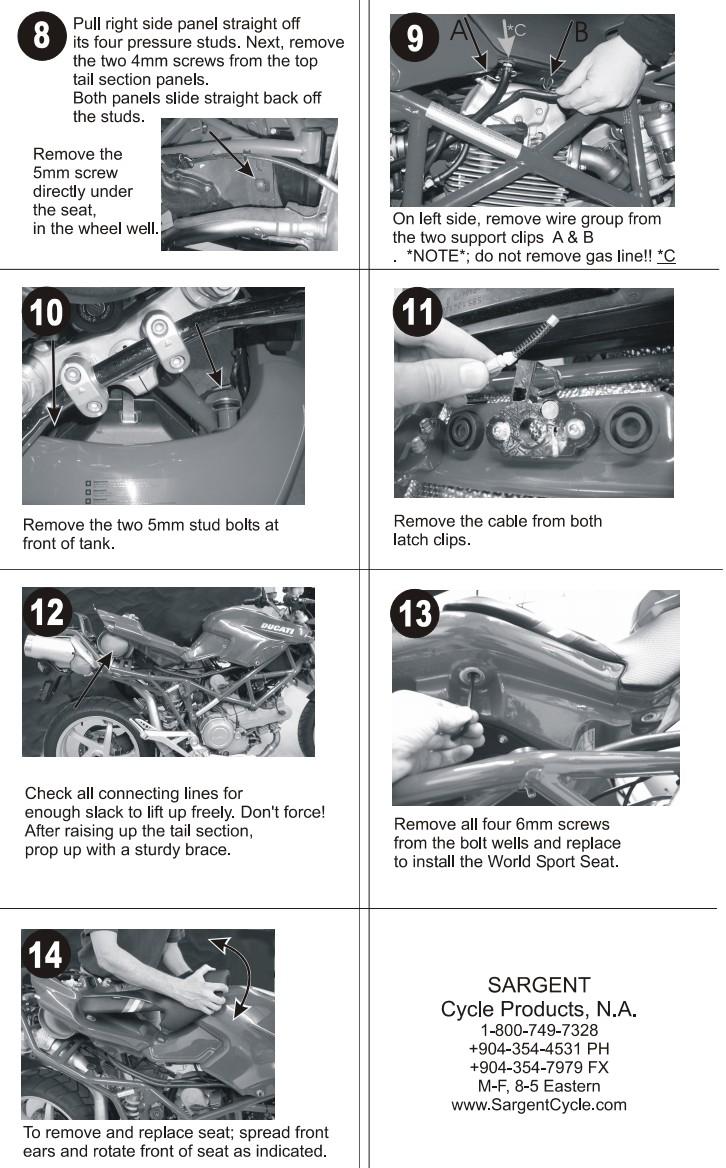
1 The California Cycleworks MTS tank provides an aftermarket alternative to the OEM nylon fuel tanks as used on aircooled Desmodue Ducati Multistrada 1100, 1000, and 620 models. This fuel tank is NOT for the newer Multistrada 1200 and 821 models. Warning: Installation of this fuel tank and parts kit should be performed by a qualified technician. Improper installation may interfere with the safety and proper operation of the product and/or vehicle. This instruction sheet cannot account for every possibility and should be used as a guide to supplement the installing technician's training and experience. Performing maintenance on the fuel system can lead to gasoline leaks, which may cause damage to property, personal injury, or death. Installation time: An experienced mechanic at a Ducati dealership may be able to complete the tank replacement in 2 to 3 hours. Home garage installation will depend on the owner's familiarity with removing the MTS's bodywork. Expect this to be a day-long project. Tools Required Ratchet, socket extension, universal joint 8mm socket, 8mm wrench, and 8mm swivel socket 4mm and 5mm hex keys (allen wrenches) or sockets 13mm wrench, 13mm deep well socket Phase 1: Remove Fairings IMPORTANT: Before starting work, ride your bike to get as much fuel out of the tank as possible. If you've never removed the fairings, please read Sargent's instructions (included at the end of this document) on how to install their seat on the MTS. If you have a work table or lift, don't put the motorcycle on it yet! You need to remove the two screws with the 8mm dished hex heads which are directly outside of the fork tubes. These are done most easily with the bike's handlebars turned to full lock. Follow the Sargent Seat instructions (at the end of this document) through step 12. On step 9, you do remove the hoses. You can perform step 11 or unbolt the lock assembly from the original fuel tank using a 5mm hex key and then drape the assembly off the left side of the bike. Remove these screws from the work area since you will not use them again; smaller screws are used with the CA Cycleworks MTS tank (provided in the parts kit). Do not remove the seat lock assembly from the frame. Phase 2: Remove Fuel Tank Under the rear of the tank, remove the screw and two nuts securing the pump cover to the tank. Remove the shouldered fairing screws from your work area since they will be replaced with the non-shouldered fairing screws provided in the parts kit. Note: The wiring connector for the flange is attached to the cover and can remain. Unclip the connector and move the cover to the side away from you. If the remaining fuel in the tank has been sufficiently reduced, one method for capturing the remaining fluid during removal is to place a bucket, large pan or funnel under the fuel flange. Begin loosening the flange screws ¼ to ½ turn at a time and fuel will begin draining from the bottom of the flange. You can then place rags under the flange, remove the screws, and lay the flange on the swingarm. You do not need to disturb the fuel hose connections. The fuel level sending unit has an electrical connector with the flange. You will need to separate the connection to fully lower the flange away from the tank. Reach in through the fuel pump flange opening and soak up as much fuel as possible. Place more rags in this area before attempting removal of the tank from the bike. Lifting up at the rear of the tank, remove the tank from the motorcycle. If the flange area hangs up on the frame, push forward on the rear of the tank while lifting to bend the tank and allow it to pass the frame. Page 1

2 Phase 3: Transfer Fuel Tank Components to New Tank Before placing the tank on a work surface, try to angle the tank over a catch pan to recover as much gasoline as possible. Place a soft towel on the surface of the new MTS tank to ensure the finish doesn't get marred. Using a 3mm hex key, remove the six screws attaching the rear vent canister assembly to the tank. Do not separate the rigid plastic hose from the vent assembly. Remove the two shoulder screws affixing the vent baffle to the OEM tank and move these out of the work area they are not reused. Loosen the hose clamp on the tank side of the baffle outlet hose and remove the hose from the tank. Set aside the vent system for installation after the new tank is in place. Open the filler cap and remove the screws with a 3mm hex key. Before installing the filler cap to the new tank, install the supplied o-ring onto the filler in addition to the original o-ring as shown: Place the filler cap on the new MTS tank and slowly and evenly tighten the 5 screws. You will see the o-ring sealing between the filler cap and the tank surface. Remove the seat from your original tank and fit the seat onto the new tank rear first, spreading the front of the seat while lowering into place. Turn the tank (with seat) over. Use the supplied MTS Seat Bolt kit to affix your seat to the new tank. The longer bolts are for the front two mounts and the shorter bolts are for the rear two mounts. Place the screws through the special caps so that the hex head of the screw fits into the cap recess. Look through the holes in the tank to sight the seat's threads and begin threading the bolts into the seat. Leave all four bolts loose until all are threaded. Now tighten the seat bolts by hand, and then another ¼ to ½ turn using the special tool. Use an 8mm wrench or socket to remove the four screws of the fuel level sending unit. Reach in the fuel flange area to help guide the wiring out of the tank while lifting up on the sending unit. Do not force anything; the wires become stiff and may break. When installing on the new tank, reach through the flange area to help guide the wires to the back of the tank. The four mounting screws are M6x1.0 threads and torque spec is 6 ft-lb or 72 in-lb. Caution: Medium force on a wrench can easily surpass the recommended torque value. Note the orientation of the passenger seat mounts. Straighten the forward tabs on them and transfer to the new tank. Tighten the screws with the mounts all the way forward. Page 2


3 Affix the stainless steel fairing mount brackets to your new tank using the four short screws (M6x12) and 5mm hex key. Check the images for proper orientation. The bottom of the brackets is the side where the mounting hole is closer to the edge. Clip the u-nuts to the brackets and transfer four mounting posts from your original tank to these brackets (these use a 4mm hex key). Transfer the remaining hardware to your tank: two fairing posts from each side and tail fairing pins. Important: Make sure the threads where these parts screw in are greased up (we recommend lithium grease) this helps prevent the inserts from spinning later on. Also ensure the 8mm insert at the bottom rear of the tank has grease in its threads. The vent assembly is not installed at this time. Phase 4: Align Fairings to New Fuel Tank The fairing brackets have oversized mounting holes to allow adjustment and fine tuning of the fairings' position. Test fit the right side fairing to the fuel tank to confirm location of the pins and the fairing bracket. Reposition the pins and their u-nuts along the slots in the brackets for the best fitment between the fairing and the fuel tank. Additional adjustment is available by loosening the brackets' mounting screws as the brackets' mounting holes are oversized. Fitting and adjustment of the bracket pins for the left fairing is made easier if the fairing is removed from the motorcycle. First, unclip the electrical connection to the sensor next to the fuse block. Using an 8mm wrench or socket, remove the two screws securing the fuse block. Now you can bring the small upper left side fairing to a table to test fit and align the fairing posts. Before continuing, make sure the fairing posts and bracket mount screws are all tightened. Page 3


. 4.")
4 Phase 5: Prepare Bike to Receive New Fuel Tank Loosen the four seat pad locking nuts with a 13mm hex wrench. There are flange nuts on the underside of the seat pads. The front two nuts can be accessed from the left side of the motorcycle. Just loosen them ½ turn. Now turn the seat pad screws clockwise (from above) 7 or 8 turns, lowering the pads to add clearance for the new seat bolt caps. Do not tighten the lock nuts this is saved for the final phase. 1. Put the loop clamps on the frame. 2. The flat part of the loop clamp is on the bottom with the holes forward. 3. Insert the bent bolts up through the loop clamps (we supply strong stainless loop clamps of the proper size so this takes some effort). 4. Shove the white tubing down on the bent bolt until threads are exposed. 5. Place an M6 nut upside down on the threads and hand tighten until the loop clamp is nearly closed. 6. Repeat on the other side. Note: Now is not the time to fit the vent tank; it is in this picture for reference. Page 4


 Connect the fuel sender connector to the flange wiring inside the tank. b) Clean the flange o-ring and apply a light coat of grease.")
5 Phase 6: Install New Fuel Tank 1. Place the tank on the motorcycle, front end first. Pay close attention to the fairing brackets! They are sharp and will scratch your front upper fairings. With the front of the tank safely in place, lower the rear of the tank. 2. At the front of the tank, double check that the front frame mount plates are aligned with the frame mounts. 3. Install the rear frame mount bolt to the tank. Lift up the rear of the tank slightly to locate the mounting hole in the tank. Use a 5mm hex key to tighten the screw. Note: This fastener should be greased to prevent the insert from spinning. The tank is shipped with grease in this insert's threads but you should double check to be sure. 4. Install the forward frame mounting screws. These are the long pins holding the front of the tank to the frame. We recommend that you clean and reapply fresh grease to the pins. 5. Install the fuel flange: a) Connect the fuel sender connector to the flange wiring inside the tank. b) Clean the flange o-ring and apply a light coat of grease. c) Note the orientation of the normal flange bolts vs the two with threads. One of the threaded stud-bolts is oriented roughly at 12 o'clock. Moving counter-clockwise, skip the next bolt and the second stud-bolt will be at 8 o'clock (see illustration to the right). d) Loosely fit all six screws before tightening any of them; then evenly tighten all to 72 in-lb. e) If the flange connector was removed from the cover, reattach it to the mount in the cover. f) Reconnect the fuel sending unit electrical connection. g) Fit the cover over the two stud-bolts and then use the provided nonshouldered fairing screw at the far right mounting point. While pressing the cover against the flange near the stud-bolts, tighten the fairing screw. Now tighten the cover's retaining nuts. 6. Install the seat lock housing to the tank using a 4mm hex key on the two socket head M5 screws provided. The cable routes outside the bent bolt used for the tank vent baffle. Note: The original screws have M6 threads; the thread size was reduced to make the mold operate better. It also allows more freedom for positioning of the seat lock. 7. Install tank vent system as outlined here: a) Lay the tank vent valve in the top rear of the tank and locate the vent baffle over the bent screws they'll be mounted to. b) Install the vent valve's six screws and tighten them. c) Affix the breather adapter tube with the smaller end in the tank vent hose and tighten both clamps. Page 5


6 d) Fit the breather to the end and secure it with the provided hose clamp. e) Twist the bent bolts for best location to hold the vent tank. To make room for the left rear fairing, position the vent tank slightly to the right of centered. Phase 7: Mount the Front Fairings Installation is the same as when you removed the fairings, only in reverse. The notes below roughly guide you through the process and to highlight key difficulties we observed in handling the fairings while developing this fuel tank. Before starting, spread grease on all the rubber grommets in your fairings; this helps them engage on the fairing posts. When fitting the fairings, you'll need to pay attention to the fairing posts: Make sure the post doesn't push the grommet to the side instead of locking into place. 1. Fit the right side fairing. Get the two fairing screws and a hex driver ready. Push the fairing onto the fuel tank's pins and then onto the fairing bracket's pins. DO NOT let go of the fairing! While one hand holds the fairing in place, start threading one of the shouldered fairing screws that secures the fairing to the motorcycle. Do not yet install the small screw with 8mm head and washer to the inside front of the fairing. Pay attention that the shoulder of the fairing screw goes into the slot in the fairing! It is easy to miss this detail and the result is the screw's shoulder will damage the edge of the fairing's mounting hole. 2. Fit the top left side fairing: Make sure the top left fairing's fuse block is bolted up and the electrical sensor is reconnected. Page 6


7 3. Get two screws with 8mm heads and their washers and while pushing back on each of the side fairings, start the screws in their threads. DO NOT TIGHTEN: Leave these loose with only a few threads engaged. 4. Fit the front chin fairing. You may need to pull the side fairings outward to get the chin piece to clear them. 5. Tighten the fairing screws at both ends of the chin fairing to secure it in place. 6. Tighten the hard-to-reach inner fairing screws with 8mm heads. We found that using a long extension with an 8mm swivel socket at the end was the most effective means of working on those screws. Note: The remaining two screws and washers for the rear inner fairing mounts will not line up with the screws so they won't be used. The forward faces of the fuel tank are too close to the rear inner mounts. 7. Affix the left side lower fairing. Page 7

8 Phase 8: Mount Rear Fairings and Passenger Seat The rear fairings are also a snug fit as the rear faces of the new tank are slightly longer than the original tank. 1. Press the right rear tail fairing onto the post at the back of the fuel tank then align the mounting point behind the grab rail with the post. 2. Repeat for the left side. Some pressure will be required to get the fairings lined up. 3. Tighten the mounting screw. Notice the passenger seat mounts are all the way forward and also the tabs are bent up to horizontal. Also shown is the configuration of the tank vent baffle system. Page 8
.")
9 Phase 9: Tighten Seat Rest Screws and Locknuts 1. Adjust the seat rest pads up until they are touching the seat bolts from your kit. 2. Bring the seat pads up to the seat nuts and turn the screws clockwise (when observed from below). If turning a pad's screw is difficult, the top of the screw just below the pad itself is a hex head, allowing a wrench to aid with tightening. 3. As the pad nears the seat bolt, you can use the seat bolt tool to prevent it from turning. 4. Tighten the seat pad locknuts. Page 9

10 Sargent Seat Installation Instructions Page 10
11 Page 11
BEW engine timing belt replacement procedure from MOGolf (as demonstrated on a 2004 Jetta).
.") BEW engine timing belt replacement procedure from MOGolf (as demonstrated on a 2004 Jetta). Based on the procedure published by Volkswagen, but modified for the "average" shadetree mechanic. Some special
BEW engine timing belt replacement procedure from MOGolf (as demonstrated on a 2004 Jetta). Based on the procedure published by Volkswagen, but modified for the "average" shadetree mechanic. Some special
INSTALLATION INSTRUCTIONS CATCH CAN KIT
 INSTALLATION INSTRUCTIONS CATCH CAN KIT FORD FIESTA ST Document: 19-0175 Support: info@radiumauto.com STEPS 1-14 COVER THE PCV SIDE CATCH CAN KIT (P/N: 20-0377) STEPS 15-35 COVER THE CRANKCASE CATCH CAN
INSTALLATION INSTRUCTIONS FOR THE MOTOR TRIKE GL1500 RAKE KIT
 INSTALLATION INSTRUCTIONS FOR THE MOTOR TRIKE GL1500 RAKE KIT Thank you for choosing the Motor Trike GL1500 Rake Kit. We ask that you read the directions before you start and follow them very closely.
Installation Manual TWM Performance Short Shifter Cobalt SS/SC, SS/TC, HHR SS, Ion Redline and Saab 9-3
 Page 1 Installation Manual TWM Performance Short Shifter Cobalt SS/SC, SS/TC, HHR SS, Ion Redline and Saab 9-3 Please Note: It is preferable to park on a flat surface, as you will have to engage and disengage
Deuce/Ace Installation Instructions
 HARDWARE KIT: Upper Mounting Plate: 2-7/16" (11mm) X 3.5" bolts 2-7/16" flange nuts 2-2" spacers 2-7/16" trim cap mounting washers 2 - plastic trim caps TOOLS NEEDED: safety glasses wrenches 16mm or 5/8"
w w w. h d o n l i n e s h o p. d e CRUISE CONTROL KIT GENERAL INSTALLATION -J04064 REV Kit Number Models Additional Parts Required
 -J006 REV. 006-08- CRUISE CONTROL KIT GENERAL Kit Number 7796-07 Models For the most up-to-date model fitment information, please see the product label or www.harley-davidson.com. Additional Parts Required.
INSTALLATION INSTRUCTIONS CATCH CAN KIT
 INSTALLATION INSTRUCTIONS CATCH CAN KIT FORD FIESTA ST Document: 19-0175 Support: info@radiumauto.com STEPS 1-14 COVER THE PCV SIDE CATCH CAN KIT (P/N: 20-0377) STEPS 15-31 COVER THE CRANKCASE CATCH CAN
2017+ L5P Duramax 3 ½ Down Pipe & EGR Fix Kit
 2017+ L5P Duramax 3 ½ Down Pipe & EGR Fix Kit Covers installation of PN s: WCF100630, WCF100829 Note: This Kit is for off road competition use only! Off Road Competition Use Tuning & Exhaust System is
STEALTH BIG AIR KIT - Yamaha Roadliner/Stratoliner and Raider
 Page: 1 If you question your abilities it may be best for an experienced service technician perform this installation. A Yamaha Service Manual would be helpful to have on hand for reference. Revision:
Installation Manual TWM Performance Kia Forte Short Shifter
 Installation Manual TWM Performance Kia Forte 2009+ Short Shifter Begin the installation by parking on a flat surface, as you will have to engage and disengage the hand brake and shift from gears to neutral.
Installation Manual TWM Performance Short Shift Kit Stage 1 and Stage 2 MazdaSpeed 6
 Page 1 Installation Manual TWM Performance Short Shift Kit Stage 1 and Stage 2 MazdaSpeed 6 Please Note: It is preferable to park on a flat surface, as you will have to engage and disengage the hand brake
RS-2 SINGLE ACTION REAR BUMPER WITH TIRE CARRIER INSTALL MANUAL FOR JEEP WRANGLER ALL MODELS.
 RS-2 SINGLE ACTION REAR BUMPER WITH TIRE CARRIER INSTALL MANUAL FOR 2007-2016 JEEP WRANGLER ALL MODELS. Rear Bumper Installation Instructions 1) Remove factory rear bumper, (this includes all tow hitch
Installation Instructions COMPETITION/PLUS SHIFTER Ford Mustang MT82 6-Speed Manual Transmission Catalog#
 Installation Instructions COMPETITION/PLUS SHIFTER 2015-2017 Ford Mustang MT82 6-Speed Manual Transmission Catalog# 3916037 Rev. 00 WORK SAFELY! For maximum safety, perform this installation on a clean,
RT1 SLIP-ON EXHAUST HONDA CBR600RR REV. A
 08-50-43733 REV. A PARTS INCLUDED Ref. Part Number Description Qty 1) 00-200-00064 Slip-on S-bend Assembly 1 2) 00-200-00088 RT1 Aluminum Muffler Assembly 1 3) 03-46-43058 Muffler Mounting Strap 1 4) 07-27-42566
Do not have any open flame or heat sources close to the installation
 March 6, 2017 IS# 791 Page 1 of 16 Thank you for purchasing a Transfer Flow, Inc. 50-gallon replacement fuel system for your 2011-16 Ford diesel short bed pickup. This system will fit any 2x4 or 4x4 crew
VRSC-DX Truck-Lite LED Headlight Installation Instructions
 VRSC-DX Truck-Lite LED Headlight Installation Instructions The following Instructions are for installing a 7 Truck-Lite LED headlight into a Harley Davidson VRSC-DX Night Rod Special fairing. Other 7 headlights
BBK LONG TUBE HEADERS (99-04 GT, Mach 1, Bullitt)
") BBK LONG TUBE HEADERS (99-04 GT, Mach 1, Bullitt) Install Time: Approx. 8-10 hrs Parts Needed: BBK Long Tube Headers Shorty mid pipe X/H O2 wiring harness extensions Hi-temp thread locker Tools Required:
BBK LONG TUBE HEADERS (99-04 GT, Mach 1, Bullitt) Install Time: Approx. 8-10 hrs Parts Needed: BBK Long Tube Headers Shorty mid pipe X/H O2 wiring harness extensions Hi-temp thread locker Tools Required:
PowerMax Diesel Upgrade For Cummins Engines
 PowerMax Diesel Upgrade For Cummins Engines 00.5-007.5 Dodge Ram With Cummins 5.9L Item 3 4 5 6 7 8 9 0 3 4 5 6 7 8 Parts List Description Turbocharger Ancillary kit 773069- (includes) Installation Instructions
MAZDASPEED3 Intercooler Instructions
 MAZDASPEED3 Intercooler Instructions Congratulations on your purchase of the COBB Tuning Front Mount Intercooler System for your 2007-2009 Mazdaspeed3. The following instructions should assist you through
Subaru Front Mount Intercooler Kit STI Subaru Front Mount Intercooler Kit STI
 Subaru Front Mount Intercooler Kit STI 2008-2014 715500 Subaru Front Mount Intercooler Kit STI 2008-2014 Congratulations on your purchase of the Subaru Front Mount Intercooler Kit STI 2008-2014. The following
INSTALLATION INSTRUCTIONS GRILLE GUARD TOYOTA TUNDRA TOYOTA SEQUOIA PART # P2067
 INSTALLATION INSTRUCTIONS GRILLE GUARD 07-14 TOYOTA TUNDRA 08-14 TOYOTA SEQUOIA PART # P2067 PARTS LIST: GRILLE GUARD 1 Grille Guard 2 10mm Cam Lever Quick Release Bolts with Special Pivot Washer 1 Driver/left
ALL AMERICAN BILLET. Front Drive System - Small Block Ford Installation Instructions
 ALL AMERICAN BILLET Front Drive System - Small Block Ford Installation Instructions Small Block Ford with AC & PS All American Billet Store (800) 764-0926 www.allamericanbilletstore.com Items needed for
2015 Mustang Lightbar (All Models) CDC#
 CDC#") 2015 Mustang Lightbar (All Models) CDC# 1511-7000-01 Components: 1 CDC Lightbar Note: READ instructions before starting installation!!! CDC Part# Driver side bracket 0511-6001-05 Passenger side bracket
2015 Mustang Lightbar (All Models) CDC# 1511-7000-01 Components: 1 CDC Lightbar Note: READ instructions before starting installation!!! CDC Part# Driver side bracket 0511-6001-05 Passenger side bracket
Triumph Brake Kit TR4A/TR250/TR6 PART # Rutherford St. P.O. Box 847 Goleta, CA FAX
 1. Lift the front of the car with a jack and place it on jackstands. Take off the front wheels. 2. Use two 9/16 combination wrenches to disconnect the soft brake line from the body and hard line connection
Short Shifter Installation Instructions For Miata, 6-speed Manual Transmission
 Short Shifter Installation Instructions For 2006-15 Miata, 6-speed Manual Transmission PART# 994-060 Required tools: 10mm deep socket Long extension Ratchet Small flathead screwdriver Phillips-head screwdriver
3 Turbo Downpipe Installation Audi A3 / Volkswagen GTI / Volkswagen Jetta 2.0L FSI/TSI Turbo CD100013
 Please take time to read and understand these installation instructions. APR recommends that installation of this system be performed by a qualified service center or professional muffler installer who
RT1 DUAL OUTLET SLIP-ON EXHAUST HONDA CBR600RR Rev B
 18-1022-723-02 08 50 44541 Rev B PARTS INCLUDED Ref. Part Number Description Qty 1) 00-200-00042 Slip-on S-bend Assembly 1 2) 00-200-01197 Stainless Steel Dual Outlet Muffler 1 3) 03-46-42766 Muffler Mounting
Front Drive System - Big Block Chevy Installation Instructions Big Block Chevy with AC & with PS
 Front Drive System - Big Block Chevy Installation Instructions Big Block Chevy with AC & with PS All American Billet Store (800) 764-0926 www.allamericanbilletstore.com Items needed for install Jack Jack
JK 3 Install Kit Instruction Pack
 JK 3 Install Kit Instruction Pack 1 Contents: Rear Sway Bar Link Instructions Spring Instructions Bumpstop Instructions Rear Track Bar Bracket Instructions Extended Brake Line Instructions Quick Disconnect
Airtail I.A.S. Suspension System for Harley Davidson
 5572 Fresca Drive, La Palma, CA 90623 714.523.8700, FAX 714.523.3220 Airtail I.A.S. Suspension System for Harley Davidson Compressor Kit Installation Instructions FLH/FLT Models with and without Cruise
Instruction Guide: Infiniti Q50 3.0L VR30DDTT "Full Down Pipes"
 480 E. Easy St. Unit #4 Simi Valley, Ca. 93065 Instruction Guide: 2016+ Infiniti Q50 3.0L VR30DDTT "Full Down Pipes" Technical support: (805) 522-3278 Monday- Friday 9a.m.- 3 p.m. PST WARNING: INSTALLATION
INSTALLATION TRUE DUAL HEADPIPES 497
 TRUE DUAL HEADPIPES 497 PARTS INCLUDED 1 Front Head Pipe 1 Rear Head Pipe 1 Front Heat Shield 1 Rear Heat Shield 1 Bracket (stamped 422-P) 1 Bracket (stamped 423-P) 2 1/2 x 1-1/4 Socket Head Cap Screw
Installation Instructions for Teraflex 2.5 Inch Lift Kit with Shocks (2010 Jeep Wrangler Unlimited)
") Installation Instructions for Teraflex 2.5 Inch Lift Kit with Shocks (2010 Jeep Wrangler Unlimited) Installation Time: 6 Hours Tools Required: Floor Jack Jack Stands Ratchet Torque Wrench 15mm Socket 15mm
Installation Instructions for Teraflex 2.5 Inch Lift Kit with Shocks (2010 Jeep Wrangler Unlimited) Installation Time: 6 Hours Tools Required: Floor Jack Jack Stands Ratchet Torque Wrench 15mm Socket 15mm
BA /02/03/04/06/07/08/13/13B/15 BIG AIR KIT (BAK) - Yamaha Road Star (99-07)
 - Yamaha Road Star (99-07)") BA-2020-00/02/03/04/06/07/08/13/13B/15 BIG AIR KIT (BAK) - Yamaha Road Star (99-07) Page: 1 Revision: 6.2-02/23/2011 Install Time: 1.5 Hours We recommend a qualified Yamaha technician install this kit
BA-2020-00/02/03/04/06/07/08/13/13B/15 BIG AIR KIT (BAK) - Yamaha Road Star (99-07) Page: 1 Revision: 6.2-02/23/2011 Install Time: 1.5 Hours We recommend a qualified Yamaha technician install this kit
AEV30308AA Last Updated: 05/31/18. 4 DUALSPORT sc SUSPENSION system for RAM 1500 air ride standard and rebel INSTALLATION GUIDE
 AEV30308AA Last Updated: 05/31/18 4 DUALSPORT sc SUSPENSION system for RAM 1500 air ride standard and rebel INSTALLATION GUIDE PLEASE READ BEFORE YOU START TO GUARANTEE A QUALITY INSTALLATION, WE RECOMMEND
CBEA/CJAA Timing belt procedure. Written by: greengeeker Photos by: DanG144, Kriesel, coalminer16. Required tools:
 CBEA/CJAA Timing belt procedure Written by: greengeeker Photos by: DanG144, Kriesel, coalminer16 Required tools: 1. Securing pin 3359 (you need two of them!) 2. Crankshaft stop T10050 3. Counter-hold tool
IMPORTANT WARRANTY & INSTALLATION INSTRUCTIONS ATTACHED
 IMPORTANT WARRANTY & INSTALLATION INSTRUCTIONS ATTACHED Please Forward All Attached Information to Consumer Warranty Not Valid Unless Returned to CORSA Performance We ask that you take a few moments to
CBEA/CJAA Timing belt procedure. Written by: greengeeker Photos by: DanG144, Kriesel, coalminer16. Required tools:
 CBEA/CJAA Timing belt procedure Written by: greengeeker Photos by: DanG144, Kriesel, coalminer16 Required tools: Securing pin 3359 (need two of them!) Crankshaft stop T10050 Counter-hold tool T10172 Special
INSTALLATION INSTRUCTIONS
 INSTALLATION INSTRUCTIONS Horizon ST Patented Multi Axis Adjustable Handlebar System for 2012-2015 BMW K1600GTL P/N: HST05078 IMPORTANT: PLEASE GIVE CUSTOMER ENCLOSED INFORMATION! Patent No: US 8,230,758
GM C10 Street Grip
 Part # 11365010/11365110-1973-1987 GM C10 StreetGrip Front Components 11369590 Delrin Control Arm Bushings 11369300 Drop Spindles 11362350/11362351 Front CoilSpring Kit 11369515 Front HQ Series Shocks
FORK FREE PISTON MODIFICATION 2011 HONDA CRF250R
 217 Lorain Place Los Gatos, California 95032 408.406.2089 www.smartperformanceinc.com www.spi-racing.com FORK FREE PISTON MODIFICATION 2011 HONDA CRF250R WHAT? All production versions of the 2011 HONDA
INSTALLATION INSTRUCTIONS FOR THE MOTOR TRIKE CROSS COUNTRY / CROSS ROADS / HARD BALL RAKE KIT
 INSTALLATION INSTRUCTIONS FOR THE MOTOR TRIKE CROSS COUNTRY / CROSS ROADS / HARD BALL RAKE KIT Thank you for choosing the Motor Trike Cross Country / Cross Roads / Hard Ball rake kit. We ask that you read
Toyota Tacoma Winch Mount Bumper Installation Instructions Tools Required: Transmission cooler relocation brackets Torque Wrench
 2016-2017 Toyota Tacoma Winch Mount Bumper Installation Instructions Tools Required: Items Included: Small flat head screw driver Winch Mount Ratchet, 10mm, 12mm, 14mm, 17mm & Skid Plate 19mm sockets Transmission
Shotgun Single Barrel HPFP install guide
 Shotgun Single Barrel HPFP install guide Thank you for your purchase of the VTT Shotgun Single Barrel HPFP upgrade! First thing to do when you open your box is to make sure all parts are in their respective
INSTALLATION & OWNER S MANUAL
 Rev. L p. 1 of 16 INSTALLATION & OWNER S MANUAL V4262 CAMO (SOFT SIDED) CAB KIT INSTALLATION & OWNER S MANUAL The contents of this envelope are the property of the owner. Be sure to leave with the owner
This is the Unpacking Guide for the Optibike Pioneer Allroad electric bicycle. The Guide provides information required to remove the Allroad from the
 This is the Unpacking Guide for the Optibike Pioneer Allroad electric bicycle. The Guide provides information required to remove the Allroad from the box and assemble it. If you have not assembled a bicycle
INSTALLATION INSTRUCTIONS
 INSTALLATION INSTRUCTIONS FUEL PUMP HANGER FORD MUSTANG: 2011+ S197 AND S550 Support: info@radiumauto.com Document# 19-0161 WARNING: DO NOT EXPOSE WORK AREA TO ANY SPARKS OR FIRE. DO NOT SMOKE WHILE WORKING
Bill of Materials: Please take time to read and understand these installation instructions.
 Please take time to read and understand these installation instructions. CORSA recommends that installation of this system be performed by a qualified service center or professional muffler installer who
I-Sheet Number Rev.B 3-1/2 OVAL BULL BAR DODGE RAM 1500
 PARTS LIST: 1 Bull Bar 2 10-1.5mm x 35mm Hex Bolts 2 Tube Brackets (Bull Bar) passenger or driver side 2 10mm Lock Washers 2 Upper Frame Brackets (models w/o tow hooks only) 4 10mm x 27mm OD x 3mm Flat
Z1 Motorsports 350Z / G35 Oil Cooler Kit Installation Manual
 Z1 Motorsports 2877 Carrollton Villa Rica Hwy Carrollton GA 30116 770.838.7777 Z1 Motorsports 350Z / G35 Oil Cooler Kit Installation Manual For 19, 25 and 34 Row Oil Cooler Kits Parts Included: 1 Aluminum
Installation Instructions INDY SHIFTER Fits: Mustang Fastback & Convertible with MT-82 Transmission Catalog #
 Installation Instructions INDY SHIFTER Fits: 2015-2018 Mustang Fastback & Convertible with MT-82 Transmission Catalog # 3916036 Watch our installation video on YouTube WORK SAFELY! For maximum safety,
Single Barrel Shotgun HPFP Install Guide
 Single Barrel Shotgun HPFP Install Guide Thank you for purchasing the VTT Single Barrel Shotgun HPFP upgrade kit! PLEASE READ THE ENTIRE GUIDE BEFORE BEGINNING INSTALLATION! The first thing you should
IMPORTANT WARRANTY & INSTALLATION INSTRUCTIONS ATTACHED TO ACTIVATE YOUR WARRANTY GO TO: CORSAPERFORMANCE.COM/WARRANTY STOP
 IMPORTANT WARRANTY & INSTALLATION INSTRUCTIONS ATTACHED Please Forward All Attached Information to Consumer Warranty Not Valid Unless Returned to CORSA Performance We ask that you take a few moments to
INSTALLATION & OWNER S MANUAL
 Rev. R p. 1 of 16 INSTALLATION & OWNER S MANUAL V4211 HARD SIDED CAB KIT and/or V4275 CAMO HARD SIDED CAB KIT INSTALLATION & OWNER S MANUAL The contents of this envelope are the property of the owner.
Instant Chat off the main page of Or simply call our tech team at
 Adjustable Fuel Pressure Regulator Kit for 2008+STI 2018-10-03 PSP-FUL-301 Thank you for purchasing this PERRIN product for your car! Installation of this product should only be performed by persons experienced
INSTALLATION INSTRUCTIONS: INDIAN SCOUT HI-OUTPUT GRENADES PART# 18554/18654
 INSTALLATION INSTRUCTIONS: INDIAN SCOUT HI-OUTPUT GRENADES PART# 18554/18654 Congratulations, you have purchased the finest exhaust system available for your motorcycle. Your Vance & Hines exhaust is designed
Slave Cylinder Weep Hole Drilling Procedure
 Slave Cylinder Weep Hole Drilling Procedure Tools Required: T20 Torx Driver T25 Torx Driver T25 Torx Bit with ¼ Ratchet Wrench 4mm Hex Key (Allen wrench) 5mm Hex Key 6mm Hex Key 8mm Hex Key 12mm Hex Key
GP1-R FULL EXHAUST SUZUKI GSX-R600 / GSX-R
 THIS EXHAUST SYSTEM IS DESIGNED FOR USE IN CLOSED COURSE RACING ONLY, AND IS NOT INTENDED FOR PUBLIC HIGHWAY USE. IN THE STATE OF CALIFORNIA, IT IS ILLEGAL TO MODIFY THE EMISSION CONTROL SYSTEM ON ANY
Z1 Motorsports 370Z/G37 Oil Cooler Kit Installation Manual
 Z1 Motorsports 2877 Carrollton Villa Rica Hwy Carrollton GA 30116 770.838.7777 Z1 Motorsports 370Z/G37 Oil Cooler Kit Installation Manual For 19, 25 and 34 Row Oil Cooler Kits Parts Included: 1 SETRAB
BRZ/FR-S 3.00 Cold Air Intake
 BRZ/FR-S 3.00 Cold Air Intake Thank you for purchasing this PERRIN product for your car! Installation of this product should only be performed by persons experienced with installation of aftermarket performance
(2) 10mm Quick Release Bolts with Pivot Washers (4) 10mm Flat Washers (2) 10mm Nylon Lock Nuts. (4) 10mm Plastic Washers
 10mm Quick Release Bolts with Pivot Washers (4) 10mm Flat Washers (2) 10mm Nylon Lock Nuts. (4) 10mm Plastic Washers") PARTS LIST: EXTREME GRILLE GUARD 1 Extreme Heavy Duty Grille Guard 2 10mm Cam Lever Quick Release Bolts with Special Pivot Washer 1 Driver/left Frame Mounting Bracket 4 10mm x 24mm OD x 2.2mm Flat Washers
PARTS LIST: EXTREME GRILLE GUARD 1 Extreme Heavy Duty Grille Guard 2 10mm Cam Lever Quick Release Bolts with Special Pivot Washer 1 Driver/left Frame Mounting Bracket 4 10mm x 24mm OD x 2.2mm Flat Washers
BEFORE BEGINNING INSTALLATION
 COMPLETE CHASSIS FUEL LINE KITS For 1996-2000 Honda Civic Equipped with B-Series Engine INSTALLATION INSTRUCTIONS PLEASE study these instructions carefully before beginning this installation. Most installations
INSTALLATION INSTRUCTIONS BULL BAR DODGE RAM 1500 PART # B-D1091;B-D2091
 INSTALLATION INSTRUCTIONS PART # B-D1091;B-D2091 PARTS LIST: Qty Description Qty Description 1 Bull Bar 10 12mm Lock Washers 2 Upper Frame Brackets (for trucks without tow hooks only) 8 12-1.75mm Hex Nuts
RHINO SUSPENSION SYSTEM INSTALLATION INSTRUCTIONS
 PARTS INCLUDED: 2 FRONT UPPER A-ARMS 2 FRONT LOWER A-ARMS 2 UNI-BALL JOINTS 2 UNI-BALL JOINT STUDS 2 UNI-BALL JOINT CAPS 2 RETAINING RINGS 1 FRONT SHOCK ASSEM. 2 DELRON STEERING STOPS 2 SHOCK MOUNT SPACERS
INSTALLATION MANUAL
 INSTALLATION MANUAL 2563000 Parts List 1 Carrier weldment 2 Support arm assembly 1 Third brake light assembly 1 Light extension bracket 1 Spare tire adjustment plate 1 Spare tire mount plate 1 Female spade
Accessory Fitting Instructions
 Accessory Fitting Instructions Kit Number Models Affected A9689 Thruxton 00 A96808 Thruxton 00 R Low Handlebar Kit Front Fairing Kit Kit Number Models Affected A97080 Thruxton 00 A97084 Thruxton 00 R Note:
INSTALLATION & OWNER S MANUAL
 INSTALLATION & OWNER S MANUAL CAB INSTALLATION INSTRUCTIONS JOHN DEERE 4000 SERIES (4500/4600/4700) (4510/4610/4710) (4120/4320/4520/4720) HARD SIDED CAB ENCLOSURE (p/n 1JD4120AS) SOFT SIDED CAB ENCLOSURE
Driver Side Support Bracket pictured in "no-tow hook" direction. Reverse direction for tow hook equipped vehicles
 PARTS LIST: 1 Bull Bar 2 10-1.5mm x 35mm Hex Bolts 2 Tube Brackets (Bull Bar) passenger or driver side 2 10mm Lock Washers 2 Upper Frame Brackets (models w/o tow hooks only) 4 10mm x 27mm OD x 3mm Flat
IAG Street Series Air / Oil Separator (AOS) For WRX
 For WRX") P IAG Street Series Air / Oil Separator (AOS) For 2015-16 WRX Part# IAG-ENG-7152 Tools Required: Ratchet, torque wrench, extensions, needle nose pliers, hose cutter, snips/scissors, flat head screw driver,
P IAG Street Series Air / Oil Separator (AOS) For 2015-16 WRX Part# IAG-ENG-7152 Tools Required: Ratchet, torque wrench, extensions, needle nose pliers, hose cutter, snips/scissors, flat head screw driver,
OIL COOLER KIT INSTALLATION INSTRUCTIONS PART NUMBER D
 OIL COOLER KIT INSTALLATION INSTRUCTIONS PART NUMBER D570-0904 APPLICATION: 2011-2012 E90 335i/xi (N55 engine) with BMW standard bumper and with stock oil cooler Congratulations for being selective enough
Sachs 48mm Closed Cartridge fork Service Manual
 Sachs 48mm Closed Cartridge fork Service Manual 1 Fork seal driver 2 Special soft jaws 3 Fork cap wrench 4 Rebound rod holding tool 5 Compression assembly holding tool 6 Retaining clip tool Special Tools
Procharger Stage II Intercooled Supercharger System (11-14 GT)
") Procharger Stage II Intercooled Supercharger System (11-14 GT) Installation Time: Approximately one day. Installed on 2012 Mustang GT 5.0/Manual Required Tools 3/8 Socket Set (Standard and Metric) 1/2
Procharger Stage II Intercooled Supercharger System (11-14 GT) Installation Time: Approximately one day. Installed on 2012 Mustang GT 5.0/Manual Required Tools 3/8 Socket Set (Standard and Metric) 1/2
INSTALLATION INSTRUCTIONS FORD F-150 2WD & 4WD RETAINS FACTORY TOW HOOKS PART #P3063
 INSTALLATION INSTRUCTIONS FORD F-150 2WD & 4WD RETAINS FACTORY TOW HOOKS PART #P3063 PARTS LIST: 1 Grille Guard 2 10-1.5mm Nylon Lock Nuts 1 Driver/Left Frame Mounting Bracket 4 12mm Plastic Washers 1
Audi A3 8P RS4-Style Grille
 Audi A3 8P RS4-Style Grille Installation Tutorial ES2717887 ES2717886 1 However you choose to lift the car into the air, always ensure the car is secured properly and that the parking brake is engaged.
Subaru 5-Speed Double Adjustable Short Throw Shifter
 Subaru 5-Speed Double Adjustable Short Throw Shifter 1999+ Subaru Impreza 5-Speed 2004-2005 Subaru Forester XT 5-Speed Congratulations on your purchase of the COBB Tuning Double Adjustable Short Throw
2013 RT / 2014RT / 2015 RT - Shock Spring Adjuster Installation Instructions
 2013 RT / 2014RT / 2015 RT - Shock Spring Adjuster Installation Instructions Billet Aluminum Adjusters (2) Shock Spring Compressors (Optional) Spanner Wrench (1) BajaRon Decals Not Shown (4) Adjuster Scuff
INSTALLATION FORK MOUNTED DRIVING LIGHTS 5008
 5008 PARTS INCLUDED 1 Right Fork Mount Assembly 1 Left Fork Mount Assembly 2 H3 Driving Light Assemblies 1 12-Pin Wiring Adapter 1 Hardware Kit for Fork Mount Driving Lights, Including: 6 5/16-18 Nylock
INSTALLATION INSTRUCTIONS FOR THE TOMAHAWK ELECTRIC REVERSE
 INSTALLATION INSTRUCTIONS FOR THE TOMAHAWK ELECTRIC REVERSE LAST UPDATED: April 2018 Thank you for choosing the Motor Trike Electric Reverse. We ask that you read the directions before you start and follow
PIKE DUAL AIR PICTORIAL INSTRUCTIONS. INSTRUCTIONS FOR INSTALLING ENDURO FORK SEALS AND CHANGING SEMI-BATH OIL in RockShox PIKE Dual Air Forks
 INSTRUCTIONS FOR INSTALLING ENDURO FORK SEALS AND CHANGING SEMI-BATH OIL in RockShox PIKE Dual Air Forks RECOMMENDED PARTS AND TOOLS -Bicycle work stand -Plastic bucket/drain pan -5mm Allen wrench -DH
IAG Street Series Air / Oil Separator (AOS) For 2017 WRX
 For 2017 WRX") P IAG Street Series Air / Oil Separator (AOS) For 2017 WRX Part# IAG-ENG-7152 Tools Required: Ratchet, torque wrench, extensions, needle nose pliers, hose cutter, snips/scissors, flathead screwdriver,
P IAG Street Series Air / Oil Separator (AOS) For 2017 WRX Part# IAG-ENG-7152 Tools Required: Ratchet, torque wrench, extensions, needle nose pliers, hose cutter, snips/scissors, flathead screwdriver,
TESLA MODEL S REAR UNDER SPOILER & DIFFUSER SYSTEM
 TESLA MODEL S Thank you for purchasing your Unplugged Performance Rear Under Spoiler & Diffuser System for the Tesla Model S! Please read this manual carefully prior to installation. REAR UNDER SPOILER
INSTALLATION INSTRUCTIONS
 INSTALLATION INSTRUCTIONS 2013-2014 Honda CBR500R/RA Tour Performance Handlebar Risers P/N: HR01087 IMPORTANT: PLEASE GIVE CUSTOMER ENCLOSED INFORMATION! Thank you for your purchase of our HeliBars. They
Shotgun Double Barrel HPFP install guide
 Shotgun Double Barrel HPFP install guide Thank you for your purchase of the VTT Shotgun Double Barrel HPFP upgrade! First thing to do when you open your box is to make sure all parts are in their respective
EXPANSION TANK PARTS LIST AND INSTALLATION GUIDE
 PARTS LIST AND INSTALLATION GUIDE PARTS LIST 2 PC APPLICATION-SPECIFIC MOUNTING BRACKETS 2 PC BLACK, ANODIZED 6061 ALUMINUM CATCH CANS 4 PC SILICONE HOSES 4 PC PLASTIC BARBED FITTINGS 4 PC WORM-GEAR CLAMPS
INSTALLATION INSTRUCTIONS
 INSTALLATION INSTRUCTIONS 2017+ BMW R9T Racer HeliBars Replacement Triple Clamp w/built in Risers Part # HRT05126 IMPORTANT: PLEASE GIVE CUSTOMER ENCLOSED INFORMATION! Thank you for your purchase of our
OIL COOLER KIT INSTALLATION INSTRUCTIONS PART NUMBER D E92 335i/xi (N55 engine) with M-Technic bumper and without stock oil cooler
 with M-Technic bumper and without stock oil cooler") OIL COOLER KIT INSTALLATION INSTRUCTIONS PART NUMBER D570-0925 APPLICATION 2011-12 E92 335i/xi (N55 engine) with M-Technic bumper and without stock oil cooler Congratulations for being selective enough
OIL COOLER KIT INSTALLATION INSTRUCTIONS PART NUMBER D570-0925 APPLICATION 2011-12 E92 335i/xi (N55 engine) with M-Technic bumper and without stock oil cooler Congratulations for being selective enough
INSTALLATION INSTRUCTIONS FOR: RE DOOR JK WRANGLER RE DOOR JK WRANGLER 3.5 STANDARD SUSPENSION SYSTEM
 RUBICON MANUFACTURING INC. 3290 MONIER CIR., RANCHO CORDOVA, CA. 95742 916-473-4600 INSTALLATION INSTRUCTIONS FOR: RE7122 2 DOOR JK WRANGLER RE7142 4 DOOR JK WRANGLER 3.5 STANDARD SUSPENSION SYSTEM Safety
SHELBY GT500
 2007-2009 SHELBY GT500 Removal of Factory Unit WARNING: 1. Radiator fluid must be handled properly. Please observe local ordinances with regards to handling and disposal. 2. Allow vehicle and components
DODGE OFF ROAD T-STYLE STEERING KIT INSTALLATION INSTRUCTIONS
 Dodge Off Road, LLC Specializing in Dodge Ram Solid-Axle 4x4 Suspension and Steering for Off Road Applications 855.9009.DOR sales@dodgeoffroad.com dodgeoffroad.com DODGE OFF ROAD T-STYLE STEERING KIT INSTALLATION
INSTALLATION PROCESS: FK003D945-7 Complete Front, Rear, and Clutch A.B.S. KIT Harley Davidson FLH Touring Models
 INSTALLATION PROCESS: FK003D945-7 Complete Front, Rear, and Clutch A.B.S. KIT 2014-2017 Harley Davidson FLH Touring Models Parts List: 4 Lines 1 Brake Light Switch Adapter 7 Single banjo bolts 2 Caliper
Installation Instructions
 Preparing your vehicle to install your brake system upgrade 1. Rack the vehicle. 2. If you don t have a rack, then you must take extra safety precautions. 3. Choose a firmly packed and level ground to
Assembly Instructions
 Assembly Instructions Part Number Description Model Approx. Assembly Time 99994-0903 Windshield Wiper Kit Mule SX 1 Hour WARNING Improper installation of this accessory could result in an accident causing
3" Side Bar. Part No. A0033S/B. PARTS LIST: Qty Part Description Qty Part Description
 ` 3" Side Bar Part No. A0033S/B Fits: 2014 - Current Chevrolet Silverado/Sierra 1500 Double Cab 2007-2013 Chevrolet Silverado/Sierra 1500 Extended Cab 2015 Chevrolet Silverado/Sierra 2500/3500 Double Cab
CAUTION: Never work on a hot exhaust system. Allow time for the vehicle to cool. Always wear eye protection when working under a vehicle.
 Please take time to read and understand these installation instructions. CORSA Exhaust System Installation We recommend that the installation of this system be performed by a qualified service center or
OIL COOLER KIT INSTALLATION INSTRUCTIONS PART NUMBER D E92 335i/xi (N55 engine) with BMW Standard bumper and with stock oil cooler
 with BMW Standard bumper and with stock oil cooler") OIL COOLER KIT INSTALLATION INSTRUCTIONS PART NUMBER D570-0924 APPLICATION: 2011-12 E92 335i/xi (N55 engine) with BMW Standard bumper and with stock oil cooler Congratulations for being selective enough
OIL COOLER KIT INSTALLATION INSTRUCTIONS PART NUMBER D570-0924 APPLICATION: 2011-12 E92 335i/xi (N55 engine) with BMW Standard bumper and with stock oil cooler Congratulations for being selective enough
<THESE INSTRUCTIONS MUST BE GIVEN TO THE END USER> B&W
 B&W Trailer Hitches 6 Hawaii Rd / PO Box 86 Humboldt, KS 66748 P:60.473664 F:60.869.903 Turnoverball Gooseneck Hitch Installation Instructions MODEL 08
Safety - Installation and Operation:
 4x4 or 4x2 Instructions EZGO Electric Cars Thank you for purchasing your 4x4 or 4x2 conversion kit. Safety at all times whether during installation or operation is utmost importance. Before After!!!!!!!!!!!!!!
Mobtown Offroad Toyota Tacoma Bolt On Rock Slider Installation Instructions
 Mobtown Offroad 2005+ Toyota Tacoma Bolt On Rock Slider Installation Instructions Tools Needed: 9/16 Box Wrench 9/16 Standard and Deep Well Socket, 3/8 Drive Ratchet, 3/8 Drive 3/4 Standard Socket 3/4
INSTALLATION INSTRUCTIONS FORD SUPER DUTY NOTE: (Vehicle Retains Tow Hook) PART # P3064
 PART # P3064") INSTALLATION INSTRUCTIONS 2011-14 FORD SUPER DUTY 250-550 NOTE: (Vehicle Retains Tow Hook) PART # P3064 PARTS LIST: Qty Description Qty Description 1 Grill Guard 2 10mm x mm Hex Bolts 1 Driver/Left Lower
INSTALLATION INSTRUCTIONS 2011-14 FORD SUPER DUTY 250-550 NOTE: (Vehicle Retains Tow Hook) PART # P3064 PARTS LIST: Qty Description Qty Description 1 Grill Guard 2 10mm x mm Hex Bolts 1 Driver/Left Lower
WRX/STI Engine Oil Cooler
 2002-14 WRX/STI Engine Oil Cooler 2014-04-21 Thank you for purchasing this PERRIN product for your car! Installation of this product should only be performed by persons experienced with installation of