3D PRINTER. Pack 10. Anything you can imagine, you can make! 3D technology is now available for you at home! BUILD YOUR OWN
|
|
|
- Rosalyn Haynes
- 6 years ago
- Views:
Transcription


1 BUILD YOUR OWN Pack 10 Anything you can imagine, you can make! 3D PRINTER Compatible with Windows 7 & 8 Mac OS X 3D technology is now available for you at home!

2 BUILD YOUR OWN 3D PRINTER CONTENTS PACK 10 Assembly Guide The next five detailed and easy-to-follow stages of construction for your 3D printer. Stage 41: Add the Z-axis and feeder motor drivers, and the feeder motor cable Stage 42: Connect up the power supply and fix it to the housing Stage 43: Connect the X-, Y- and Z-axis limit switches to the driver board Stage 44: Attach two brackets to the housing and add a linear bush to the modelling table Stage 45: Add a second linear bush to the table All rights reserved 2016 Published in the UK by De Agostini UK Ltd, Battersea Studios 2, 82 Silverthorne Road, Battersea, London SW8 3HE Published in the USA by De Agostini Publishing USA, Inc., 121 E. Calhoun Street, Woodstock, IL WARNING: Not suitable for children under the age of 14. This product is not a toy and is not designed or intended for use in play. Items may vary from those shown. TM


 x 1 3: Cable ties x 4 4: USB cable x 1 You will need Ruler Marker pen Scissors")

3 Stage 41: Add the Z-axis and feeder motor drivers, and the feeder motor cable Stage 41 Assembly Area In this stage, you add the Z-axis motor driver to the driver board, then add the feeder motor driver before plugging the feeder motor cable into the driver board. The two motor drivers you add to the driver board this time are identical to each other and also to the two you added in Stage 39. This time the motor drivers are for the Z-axis and feeder motors. Remember to make sure they are fully seated and that they are plugged in the right way round. You then secure the feeder motor cable to the housing and plug it into the driver board. Finally, connect your PC to the circuit board using the USB cable Stage 41 Components 1: Motor drivers x 2 2: Feeder motor cable (650mm) x 1 3: Cable ties x 4 4: USB cable x 1 You will need Ruler Marker pen Scissors PC to connect to idbox via USB cable Parts to have ready 1 2 Z-axis motor driver goes here Feeder motor driver goes here Have a look at the driver board and the diagram, left make sure you know where to plug in the Z-axis motor driver and the feeder motor driver. Locate the feeder motor cable plug, below. Get ready the printer housing and turn it so that the front is facing you. Feeder motor cable plug 149


")
4 Plug the motor drivers into the driver board 3 Circular element CAUTION! Make sure that the circular element on the top of the motor driver is on the left when viewed with the front of the housing facing you. Be careful not to touch this element. Hold one of the motors drivers as shown and plug it into the position for the Z-axis motor driver (see previous page, Step 2). Make sure that the circular structure on the driver is aligned as shown above. Hold the driver parallel to the driver board while you plug it in slowly and firmly until it is in all the way. 4 CAUTION! Make absolutely certain that the motor drivers are correctly plugged in, with their pins in the correct sockets and the circular structures to the left. Failure to do so might result in fire during operation of the printer. Now plug the other motor driver into the position for the feeder motor driver. Again, press firmly while holding it parallel to the driver board until it is fully inserted. Ensure the driver motors are not at an angle to the driver board and that the pins are all the way in. Attach the feeder cable to the housing, then plug it into the driver board 5 6 Align with 12cm mark With a marker pen, make a mark on the feeder motor cable 12cm in from the end of the cable, measuring from the smaller (motor end) connector. Turn the housing so the rear panel is facing you. Put a cable tie through each of the four sets of holes outlined in red in the image above left. Align the tie at the top right with the mark on the feeder motor cable and, with the motor end socket on the right, tighten the cable tie around the cable. Trim off the excess cable tie with scissors. 150


 and plug the connector into the pins (outlined in yellow, above)")


.")
5 7 8 9 At the other three cable tie positions (outlined in red, above), use the cable ties to secure the feeder motor cable and the spiral tube to the housing. When you ve done up each cable tie, trim off the excess with scissors. Pass the feeder motor cable through the hole in the casing to the left of the noise filter. Turn the housing so the front is facing you. Untwist the feeder motor cable you ve just passed into the housing (if necessary) and plug the connector into the pins (outlined in yellow, above) on the motor board for the feeder motor cable. Check the power supply from a computer to the circuit board 10 There are two different connectors on the USB cable supplied this time. The smaller, squarer one is the B-type and is plugged into the idbox. The wider, flatter one is the A-type, and this is plugged into the USB port on a computer. 11 Plug in B type A type B type A type Plug in With the right side of the printer facing you, plug the B-type connector of the USB cable into the USB port on the circuit board. 12 USB symbol The circuit board is powered via the USB cable by your computer. When you connect the USB cable to your computer you should see a green light come on on the circuit board (lower photo). Check this, then remove the USB cable and keep it safe. With your computer turned on, plug the A-type USB connector into a USB port on the computer. Stage finished The Z-axis motor and feeder motor drivers have been fitted to the driver board and the feeder cable has been plugged into the driver board. 151


 2 Incorrect The printer housing.")
6 Stage 42: Connect up the power supply and fix it to the housing Stage 42 Assembly Area In this stage, you will wire up the power supply, then attach it to the housing. After that, connect up more of the wiring inside the housing. It is vital to get the wires connected properly, so take care as you do it. The power supply has no fewer than nine terminals to which you attach cables in this stage. After wiring up the power supply, you attach it to the inside of the base of the housing and connect it to the thick power cables, the fan cables and the noise filter. Make sure you follow the instructions carefully and be sure to check over your assembly so you can be certain that the cables are all connected properly. This is extremely important, as if the cables are not correctly wired up, there is a real danger that the printer will fail when the power is switched on Stage 42 Components 1: Power supply x 1 2: Power lines x 2 3: Earth wire x 1 4: Power supply wires for the fans x 2 5: M3 truss head screws x 4 You will need Phillips screwdriver size 1 Phillips screwdriver size 2 5 Parts to have ready 1 Set the input voltage to 230V (for UK) 2 Incorrect The printer housing. There is a switch on the side of the power supply where you can select the input voltage from the mains to the power supply. For the UK, make sure it is switched to 230V and not 115V. 152


7 Connect up the nine screw terminals on the power supply 3 9 screw terminals Gap when screw is loosened There are nine screw terminals on the end of the power supply. Use a size 2 Phillips screwdriver to loosen them all before you start attaching cables. 4 When you insert the Y-shaped end of a cable into a screw terminal, do it so the crimp mark is uppermost so it goes in securely. Plug in Crimp mark Plug the Y-shaped end of one of the yellow power lines into the terminal on the left with the letter L above it. Tighten the screw of the terminal with the screwdriver Earth symbol Black wire Pink wire Plug the second of the two yellow power lines into the terminal with the letter N above it and tighten the screw. Plug the green Earth cable into the terminal with the Earth symbol above it and tighten the screw. 153 Plug the black wire for the fan power supply line into the fourth terminal from the left, which has COM above it. Put the pink wire into the seventh terminal, which has +V above it. Tighten the screws.


8 Right 8 9 Left Turn the housing so its left side is facing you. Place the power supply as shown, so it is to the right of the housing. Pass the rightmost of the two thick pink power cables from the driver board through the opening in the front panel of the housing and plug it into the rightmost terminal of the power supply, which has +V above it, and tighten the screw Pass the second thick pink cable from the driver board through the hole in the front panel and plug it into the power supply s eighth terminal from the left, which has a +V above it, and tighten the screw. CAUTION! It is very important that the wires connected to the power supply are in the correct terminals. Check particularly that the pink and black wires are in the correct positions as shown below. Take the rightmost of the two thick black cables from the driver board and plug it into the sixth from the left of the power supply s terminals, which has COM above it, and tighten the screw. Take the other thick black cable from the driver board and plug it into the fifth from the left of the power supply s terminals, which has COM above it, and tighten the screw. Attach the power supply to the housing Rotate by 90 degrees Pass the power supply through the front panel (you ll have to angle it to get it through). Make sure the cables do not go under the power supply, and beware of damaging the housing while you manoeuvre the power supply. With the front panel facing you, rotate the housing by 90 degrees so it lies on its right panel. Support the power supply while you do this. 154


9 14 15 Hold the power supply in position with one hand so that the four screw holes in its underside align with the screw holes in the bottom panel (ringed in red). Insert an 8mm M3 truss head screw into each of the screw holes and screw them in with your fingers. Tighten all four of the screws with a size 1 Phillips screwdriver. Connect the remaining cables 16 Plug on Plug on The noise filter has three metal pins. Of these, two are side by side and have a black cover to their bases. These are the pins for the power lines. The other pin is for the Earth wire. Make sure you plug the correct wires onto the correct pins. Earth wire Power lines Turn the housing so its base is back on your work surface. Plug the two yellow power supply lines as shown above onto the two lower terminals of the noise filter, which is at the rear left of the housing. Push them all the way on, firmly yet gently When tidying the thick power cables to the bottom of the housing, unplug the motor cables one at a time and plug them back in as soon as you can to avoid mixing them up. Plug the connector of the green Earth wire onto the central, upper metal pin on the noise filter. Tuck the four thick power cables (two black, two pink) into the bottom of the housing, as shown above left and above right. If you unplug any of the connectors from the driver board while you do this, make sure you get them back into the correct locations. 155


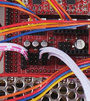
10 19 The fan power connectors are designed to be put together so the ribs on one side of the smaller connectors fit into the slots on the larger connectors. Slots Ribs Correct Take the connector for one branch of the fan power supply wires, and plug it into the connector for the fan at the lower back right of the housing. (The connector leading to the fan can be connected to either branch.) Incorrect 20 Plug the connector for the fan in the printer head into the connector on the other branch of the power supply wires. 21 In the photo, you can see where the various cables you have connected up in this stage run from and to. In the next stage, more cables are added, and the wiring is tidied up with cable ties. Stage finished The power supply terminals have been wired up, and the power supply has been fixed inside the housing. 156


 x 2 5: M3 washers")
11 Stage 43: Connect the X-, Y- and Z-axis limit switches to the driver board Stage 43 Assembly Area In this stage, you connect up the three limit switches to the driver board using the two cables supplied with this stage and the one supplied with Stage 3. You will also plug in the thermistor cable to the driver board and tidy up the cables. When you insert the pins on the limit switches into the connectors on the ends of the cables, be sure to do this carefully and not bend the pins. Make sure you get the connectors in the correct positions on the driver board. Secure the limit switch cables using ties supplied with this stage and others attached to the housing in Stage 39. After you have plugged the thermistor cable into the driver board, tidy up the cables in the bottom of the housing Stage 43 Components 1: Limit switch cables x 2 2: Cable ties x 6 3: Brackets x 2 4: M3 truss head screws (14mm) x 2 5: M3 washers x 2 6: M3 nuts x Tools you will need Scissors Parts to have ready 1 Get ready the printer housing and the limit switch cable that was supplied with Stage


12 Connect the cables to the limit switches X-axis limit 2 3 switch Y-axis limit switch The sides of the connectors are different. Make sure you plug them in so the metal parts show. Z-axis limit switch Plug in Connector's metal parts Pin base Metal shows on this side The Z- and X-axis limit switches are at the rear and the Y-axis limit switch is on the right. Connect the X-axis limit switch first. Turn the cable s connector so that you can see the side where the metal parts show. Plug it in carefully from below until just the bases of the switch s pins are visible. 4 5 Plug in Pins on switch Plug in Pins on switch Connector's metal parts Now connect the Z-axis limit switch. Carefully plug the pins on the switch into the sockets on the connector, making sure the metal parts of the connector are visible, as shown above. Connector's metal parts Turn the printer housing so its left side is facing you, and plug in the Y-axis limit switch cable connector from below. Again, put in the connector so its metal parts are showing. Connect the limit switch cables to the driver board 6 You must get the connectors from the limit switches plugged into the correct sets of pins or the printer will not operate properly. Take care! X-axis (1st column on the right) Turn the printer housing so the front panel is facing you and find the location of the pins for the limit switch cables, outlined in yellow above, and shown in close-up on the right. Z-axis (6th column from right) Y-axis (3rd column from right) 158
 Untwist the cable from the X-axis limit")


 Untwist the cable from the Y-axis limit")

 Untwist the cable from the Z-axis limit the")

13 7 Metal parts facing left X-axis (1st column on the right) Untwist the cable from the X-axis limit switch, if necessary, and plug the connector into the first column of pins on the right. The side of the connector where the metal parts are visible should be facing to the left. 8 Metal parts face left Y-axis (3rd column from right) Untwist the cable from the Y-axis limit switch if necessary, and plug the connector into the third column of pins from the right. The side of the connector where the metal parts are visible should be facing to the left. 9 Metal parts face left Z-axis (6th column from right) Untwist the cable from the Z-axis limit switch, if necessary, and plug the connector into the sixth column of pins from the right. The side of the connector where the metal metal parts are visible should be facing to the left. 159


, and do it up.")


14 Secure the limit switch cables to the housing 10 Rear Turn the housing so its rear panel is facing you. Pass cable ties through the two sets of holes (outlined in red) and do up the ties to secure the cables for the X-axis limit switch, as shown above. Trim the excess from the cable ties with scissors Put the X-axis limit switch cable together with the X-axis motor cable and bind them to the housing with the upper cable tie inserted (but not tightened) in Stage 39. Add the Z-axis limit switch cable to the bundle of the X-axis limit switch and motor cables at the lower cable tie (Stage 39), and do it up Trim off the excess from the straps of the ties and turn the housing so the front is facing you so you see how the cables have been fixed in place. Cable in gap Turn the housing so its right panel is facing you. Pass cable ties through the two sets of holes (outlined in red), and do up the ties to secure the cables for the Y-axis limit switch, as shown above. Trim off the excess from the cable ties. Move the Y-axis limit switch cable into the gap between the power supply and the housing, as shown above. 160


15 Connect the thermistor cable to the driver board 16 Thermistor cable Thermistor connector 17 T0 Pins The thermistor, which is in the head block, has a cable that needs to be connected to the driver board. Locate the thermistor cable, which emerges from the spiral wrap that enters the rear of the housing. The pins on the driver board for the thermistor are the two on the right (with T0 by them) in the row of six pins in front of the Z-axis motor connector. The thermistor connector can be plugged in either way. Plug in connector Gather together the cables at the bottom of the housing 18 Start by gathering together the cooling fan cable and the X-axis and feeder motor cables. Make loops in the cables if necessary to make the bundle neater, then bind them together with a cable tie as shown above, trimming the excess with scissors. 19 Stage finished The limit switch cables have been connected and the thermistor cable plugged into the driver board. The cables in the bottom of the housing have been tidied up. Store the parts Next, gather the Z- and X-axis limit switch and the thermistor cables into a neat bundle and bind them with a cable tie. Note that the Y-axis limit switch, the Y-axis motor, the power supply and the cartridge heater cables are not held together. Keep the brackets, washers, nuts and truss head screws supplied but not used with this stage somewhere safe. 161
.")


 x 4 3: M3 spring washers x 4 4: M3 flat washers x 4 5: M3")
 PVA glue Parts to have ready 1 2 Table You will need the housing and the table that you last worked on in Stage 11.")
16 Stage 44: Attach two brackets to the housing and add a linear bush to the modelling table In this stage, you will attach two brackets to the housing, then add a linear bush to the table base using cap bolts (bolts with hexagonal sockets in their heads). The bush acts as a bearing that keeps the table moving smoothly up and down on the Z-axis rods. Stage 44 Assembly Area When you add the brackets to the printer housing one on the left and one on the right you might find that adding a bit of PVA glue to hold the nuts in position will make it easier to do the assembly. As usual when working with acrylic, do not apply too much force when tightening the screws into the nuts; use just enough to tighten them securely. The same advice apples when you add the linear bush to the table, especially as it is easy to apply much more force using an Allen key. Stage 44 Components : Linear bush x 1 2: M3 cap bolts (15mm) x 4 3: M3 spring washers x 4 4: M3 flat washers x 4 5: M3 nuts x 4 6: Allen key (50 x 2.5mm) 4 You will need 5 Phillips screwdriver size 1 Allen key (50 x 2.5mm) PVA glue Parts to have ready 1 2 Table You will need the housing and the table that you last worked on in Stage 11. Also the two truss head screws, washers, nuts and brackets from Stage 43. Peel the protective coverings off both sides of the brackets. 162 Put an M3 flat washer on each of the 14mm M3 truss head screws. And put a nut into each of the nut slots in the brackets. You can, if you wish, fix the nuts in place with a drop of PVA glue to stop them falling out.

 into the nut as shown, and")

 at the top left, locate")

 in the bush.")


17 Attach the brackets to the left and right surfaces of the housing Insert Insert the tab of one of the brackets into the slot (outlined in red) in the left of the housing as shown above. Screw the 14mm truss head screw (with washer) into the nut as shown, and tighten it with a size 1 Phillips screwdriver. Repeat the process for the other bracket on the right of the housing. Attach the linear bush to the table base 6 Dog Hole for linear bush 7 8 Screw holes With the dog (protective metal plate) at the top left, locate the circular hole surrounded by four screw holes in the table base where the linear bush is to be attached. 9 Put the shaft of the bush through the hole and put a 15mm M3 cap bolt through each of the screw holes (ringed in red) in the bush. Hold the bolts in position and turn the table over. Stage finished Put an M3 flat washer, then an M3 spring washer over the shafts of each of the bolts and then screw an M3 nut onto each bolt with your fingers. Turn the table again and, holding the nuts with your fingers, tighten each of the cap head bolts with the 50 x 2.5mm Allen key. 163 Two brackets have been attached to the housing and a linear bush has been added to the table base.


18 Stage 45: Add a second linear bush to the table Stage 45 Assembly Area This assembly is much the same as part of that in the previous stage (Stage 44), where you added a linear bush to the table base, fastening it in place with four cap head bolts. Remember to make sure the bush is the right way up in its hole in the table. In this stage, the linear bush is put through a hole in the top left of the table, before being secured in place with the four cap head bolts supplied with this stage. Remember that when putting the washers onto the shaft of a bolt, the M3 flat washer goes on before the spring washer. The spring washer is followed by the nut. When you have secured the bush with the nuts, tighten the bolts using the 50 x 2.5mm Allen key supplied with Stage 44. Lastly, check and adjust the alignment of the metal dog, which is next to the newly-added linear bush Stage 45 Components 1: Linear bush x 1 2: M3 cap bolts (15mm) x 4 3: M3 spring washers x 4 4: M3 flat washers x 4 5: M3 nuts x You will need Allen key (50 x 2.5mm) supplied with Stage 44 Parts to have ready 1 Get ready the table you worked on in Stage


19 Attach the linear bush to the table base 2 3 Hole for linear 4 Dog bush Screw holes With the dog at the top left, locate the circular hole surrounded by four screw holes at the top left of the table base where the second linear bush is to be added. Put the shaft of the bush through the hole and put a 15mm M3 cap bolt through each of the screw holes (ringed in red) in the bush. Hold the bolts in position and turn the table over. Put an M3 flat washer and then an M3 spring washer over the shafts of each of the bolts. 5 6 After you ve put the washers onto each bolt, screw an M3 nut onto each of the four bolts with your fingers. Turn the table and, holding each of the nuts with your fingers, tighten the cap head bolts in turn with the 50 x 2.5mm Allen key. Adjust the position of the dog 7 Levels are different Stage finished Underside aligned with table Because it is difficult to adjust the dog after the table has been assembled into the housing, now is the time to check its alignment. Ensure that the underside is aligned with the table (as shown above) and tighten the screw to secure it in position. 165 The second linear bush has been added to the table. Put the table somewhere safe until it is time to add it to the housing.


20 User Guide BUILD YOUR OWN 3D PRINTER TM 166
3D PRINTER. Pack 09. Anything you can imagine, you can make! 3D technology is now available for you at home! BUILD YOUR OWN
 BUILD YOUR OWN Pack 09 Anything you can imagine, you can make! 3D PRINTER Compatible with Windows 7 & 8 Mac OS X 3D technology is now available for you at home! www.model-space.com BUILD YOUR OWN 3D PRINTER
BUILD YOUR OWN. Pack 16
 BUILD YOUR OWN TM Pack 6 0 CONTENTS Assembly Guide 43 Stage 5: The left fuel tank base Stage 5: The engine cables Stage 53: The LED tester Editorial and design by Continuo Creative, 39-4 North Road, London
Build your own. Pack. Stages 39-42: Receive more of Robi s electrical components
 Build your own Pack 11 Stages 39-42: Receive more of Robi s electrical components Build your own All rights reserved 2016 CONTENTS Published in the UK by De Agostini UK Ltd, Battersea Studios 2, 82 Silverthorne
Build your own THUNDERBIRD 2
 PACK 11 PAGE 67 Pod 4 ramp tracks and Jet Air Transporter 224 68 Left rear booster and Alan s Racing Car 227 69 Right rear booster and Alan s Racing Car 230 70 Left booster speaker 233 71 Right rear booster
Build the legendary PORSCHE RS 2.7. Pack 5
 Build the legendary PORSCHE RS 2.7 Pack 5 Build the legendary P O R S C H E RS 2.7 Contents PAGE STAGE 29 Rear disc brake 120 30 Rear wheel 123 31 Rear disc brake 126 32 Rear wheel 129 33 The crankcase
Build your own THUNDERBIRD 2
 PACK 03 PAGE 12 Pod 3 front hatch and Elevator Car 2 43 13 Pod 3 rear hatch and Elevator Car 2 46 14 Pod 3 floor and Elevator Car 2 49 15 Pod 3 frames and FAB 1 52 16 Pod 3 frames and FAB 1 55 17 Pod 3
The front wheel and mirror
 Pack 01 1 The fuel tank 3 2 The front wheel and mirror 5 3 The headlight 6 Editorial and design by Continuo Creative, 39-41 North Road, London N7 9DP. Published in the UK by De Agostini UK Ltd, Battersea
Build your own THUNDERBIRD 2
 PACK 06 PAGE 33 Telescopic legs C and I.R.3 112 34 Telescopic legs D and I.R.3 115 35 Leg bases and Thunderizer 118 36 Landing feet and Elevator Car 3 121 37 Leg rail-gear racks and Elevator Car 3 124
Build your own THUNDERBIRD 2
 PACK 04 PAGE 19 Pod 3 base 66 20 Pod 3 details and Firefly 69 21 Pod 3 laboratory and Firefly 72 22 Pod 3 floor details and Firefly 75 23 Pod 3 inspection walkways 78 24 Pod 3 right inner wall 81 25 Pod
Build your own THUNDERBIRD 2
 PACK 12 STAGE PAGE 74 Tailwing ramjets and Cobra Half-track 247 75 Tailwing intakes 250 76 Tailwing fins 253 77 T2 control board 255 78 T2 wings and Mobile Crane 258 79 T2 side frames and Mobile Crane
Build the legendary PORSCHE RS 2.7. Pack 3
 Build the legendary PORSCHE RS 2.7 Pack 3 Build the legendary P O R S C H E RS 2.7 Contents PAGE STAGE 13 The rear engine cover 55 14 The left intake manifolds and throttle bodies 59 15 The right intake
Prusa i3 Printer Assembly Guide
 Prusa i3 Printer Assembly Guide Special thanks to Carlos Sanchez and Miguel Sanchez for the graphics. All graphics captured from their great animation: http://www.carlos-sanchez.com/ Prusa3/ For copyright
Build the legendary PORSCHE RS 2.7. Pack 12
 Build the legendary PORSCHE RS 2.7 Pack 12 Build the legendary P O R S C H E RS 2.7 Contents PAGE STAGE 92 The rear shelf 368 93 The engine cover 372 94 The engine cover hinges 376 95 The rear panel 380
8. Electronics assembly (B3/R2 design)
") 8. Electronics assembly (B3/R2 design) Written By: Jakub Dolezal 2018 manual.prusa3d.com/ Page 1 of 31 Step 1 Tools necessary for this chapter Needle-nose pliers for zip tie trimming. 2.5mm Allen key for
8. Electronics assembly (B3/R2 design) Written By: Jakub Dolezal 2018 manual.prusa3d.com/ Page 1 of 31 Step 1 Tools necessary for this chapter Needle-nose pliers for zip tie trimming. 2.5mm Allen key for
Build your own THUNDERBIRD 2
 PACK 01 STAGE PAGE 01 Nose assembly and Elevator Car rear wheels 3 02 Cockpit interior and Elevator Car 1 completion 7 03 Missile launcher and Thunderbird 4 11 04 Nose assembly and the Tracy brothers 15
FlexJet Carriage Circuit Board (PCB) Replacement
 Replacement") P/N: 111484 R0 14140 NE 200th St. Woodinville, WA. 98072 PH: (425) 398-8282 FX: (425) 398-8383 ioline.com FlexJet Carriage Circuit Board (PCB) Replacement Notices: Warning! Ensure that all AC power cables
P/N: 111484 R0 14140 NE 200th St. Woodinville, WA. 98072 PH: (425) 398-8282 FX: (425) 398-8383 ioline.com FlexJet Carriage Circuit Board (PCB) Replacement Notices: Warning! Ensure that all AC power cables
Build the. Steam Locomotive. Pack 01
 Build the Steam Locomotive Pack 01 Build the Steam Locomotive Contents Step by step Stage 01: The smokebox door Stage 02: The smokebox Stage 03: The first driving wheels and coupling rods Stage 04: The
FlexJet - Flex Cable Replacement
 P/N: 109515R0 14140 NE 200th St. Woodinville, WA. 98072 PH: (425) 398-8282 FX: (425) 398-8383 FlexJet - Flex Cable Replacement Notices: Warning! Ensure that all AC power cables are removed from the printer
Replacing a Load Cell in the 400 Series Force Plate
 Replacing a Load Cell in the 400 Series Force Plate Determining which load cell is faulty You will first need to determine which load cell is at fault. To do this you will need the XPV7 diagnostic software.
INSTALLATION INSTRUCTIONS
 INSTALLATION INSTRUCTIONS Accessory Application Publications No. SYSTEM S2000 AII 26324 Issue Date OCT 2004 PARTS LIST Headrest Speaker System P/N 08A54-S2A-100 3 Small wire ties 2 Headrest speakers 9
Fitting Instructions For The TDV6 EGR Blanking Kit To A 2006 Model Discovery 3 TDV6 GHSE
 Part Number DA1112 Fitting Instructions For The TDV6 EGR Blanking Kit To A 2006 Model Discovery 3 TDV6 GHSE You do this modification at your own risk. Britpart won t be held responsible for what is written
Setup, Assembly, & Adjustment
 Setup, Assembly, & Adjustment 34877 Rev. B 1 of 8 Melco Fast Clamp Instructions The Melco Fast Clamp is a versatile clamping system for your embroidery machine. This document will walk you through the
INSTALLATION INSTRUCTIONS FOR MK4 VOLKSWAGEN JETTA (BORA) /GOLF 1.8T, 2.0L, VR6, & R32 MODELS ALSO FITS ALL MODELS OF SEAT LEON & TOLEDO
 /GOLF 1.8T, 2.0L, VR6, & R32 MODELS ALSO FITS ALL MODELS OF SEAT LEON & TOLEDO") CI100001 INSTALLATION INSTRUCTIONS FOR 1999.5-2005 MK4 VOLKSWAGEN JETTA (BORA) /GOLF 1.8T, 2.0L, VR6, & R32 MODELS ALSO FITS ALL MODELS OF SEAT LEON & TOLEDO Thank you for choosing to purchase a Carbonio
CI100001 INSTALLATION INSTRUCTIONS FOR 1999.5-2005 MK4 VOLKSWAGEN JETTA (BORA) /GOLF 1.8T, 2.0L, VR6, & R32 MODELS ALSO FITS ALL MODELS OF SEAT LEON & TOLEDO Thank you for choosing to purchase a Carbonio
Supply Valve Replacement
 This procedure is to help facilitate the replacement of the25.1-25.4 supply valves. Solenoid Supply Valves Note: You will need the following tools: Socket Wrench with extension and a 3/8 Socket Size 1
Installation Manual TWM Performance Short Shifter Cobalt SS/SC, SS/TC, HHR SS, Ion Redline and Saab 9-3
 Page 1 Installation Manual TWM Performance Short Shifter Cobalt SS/SC, SS/TC, HHR SS, Ion Redline and Saab 9-3 Please Note: It is preferable to park on a flat surface, as you will have to engage and disengage
RMK HANDLEBAR KIT P/N ; ; APPLICATION BEFORE YOU BEGIN KIT CONTENTS. Verify accessory fitment at Polaris.com.
 RMK HANDLEBAR KIT P/N 2883835; 2883836; 2883837 APPLICATION Verify accessory fitment at Polaris.com. BEFORE YOU BEGIN Read these instructions and check to be sure all parts and tools are accounted for.
GENUINE PARTS INSTALLATION INSTRUCTIONS
 GENUINE PARTS INSTALLATION INSTRUCTIONS 1. 2. 3. 4. DESCRIPTION: Accent light Kit APPLICATION: Infiniti JX (2013) PART NUMBER: 999F3 YY000 - Universal Accent Lighting Kit. KIT CONTENTS: Item QTY Description
INSTALLATION INSTRUCTIONS
 INSTALLATION INSTRUCTIONS Accessory Application Publications No. All 12035 SYSTEM 2012 RIDGELINE Issue Date NOV 2011 PARTS LIST Security System Attachment Kit: P/N 08E55-SJC-101 Flange bolt Unit bracket
5. E-axis assembly. 5. E-axis assembly. Written By: Jakub Dolezal manual.prusa3d.com/ Page 1 of 40
 5. E-axis assembly Written By: Jakub Dolezal 2018 manual.prusa3d.com/ Page 1 of 40 Step 1 Tools necessary for this chapter Needle-nose pliers for zip tie trimming. 2.5mm Allen key for M3 screws 2mm Allen
Modix Big-60 Assembly Instructions Part 1
 Modix Big-60 Assembly Instructions Part 1 Version 1.0, October 2017 Menu 1. X Idler Pulley Assembly... 3 2. Connecting X Axis Brackets to Z Profiles... 4 3. Assemble X Rails on X Top Profiles... 6 4. Assemble
INSTALLATION INSTRUCTIONS
 INSTALLATION INSTRUCTIONS Model: 8510 & 8510TK Ford E Series Van 1994 2002 with stock power mirrors Tools required for the installation are: 7/16 socket, T20 screwdriver or 8mm socket, screwdriver, phillips
Modix Big-60 Assembly Manual Part 2
 Modix Big-60 Assembly Manual Part 2 Version 1.0, October 2017 Menu 1. Motors & End Stop Wiring... 3 2. Controller Wiring Check... 6 3. Extruder Wiring... 7 4. Electronic Box Cover... 9 5. Filament Sensor...
Making Instructions Version 2.1 for Windows
 Making Instructions Version 2.1 for Windows Ohbot Ltd. 2017 About Ohbot has seven motors. Each connects to the Ohbrain circuit board and this connects to a computer using a cable. Ohbot software allows
Installation Instructions for the Plug & Play Remote Start Package (EVOCHR5)
") T6018 v1.1 02/2013 Installation Instructions for the Plug & Play Remote Start Package (EVOCHR5) For DODGE Nitro 2007-2011 Review the remote start installation manual for safety instructions! Overview Your
T6018 v1.1 02/2013 Installation Instructions for the Plug & Play Remote Start Package (EVOCHR5) For DODGE Nitro 2007-2011 Review the remote start installation manual for safety instructions! Overview Your
5. Extruder Assembly
 5. Extruder Assembly Guide for the assembly of the Extruder. Written By: Josef Prusa 2018 manual.prusa3d.com/ Page 1 of 24 Step 1 Get the necessary tools 2.5 and 1.5 mm Allen key Needle-nose pliers 2018
Installation Instructions for the Plug & Play Remote Start Package (EVOCHR4)
") T6002 v1.1 02/2013 Installation Instructions for the Plug & Play Remote Start Package (EVOCHR4) For CHRYSLER Town & Country 2008-2012 Review the remote start installation manual for safety instructions!
T6002 v1.1 02/2013 Installation Instructions for the Plug & Play Remote Start Package (EVOCHR4) For CHRYSLER Town & Country 2008-2012 Review the remote start installation manual for safety instructions!
Installation Instructions
 Installation Instructions Jeep JK 2-Door (2011 Present) Mounting Bracket and Air Line System Kit for ARB On-Board Twin Air Compressor (CKMTA12) Made in the USA Kit Contents: 1 Flat Bracket 1 Formed Bracket
The H-MAC Heavy Metal Articulating Chassis Construction Guide
 The H-MAC Heavy Metal Articulating Chassis Construction Guide The Heavy Metal Chassis is constructed with two identical drive modules built using 10 mechanical sub-assemblies. The drive modules are integrated
Product Description. Product Numbers. Warning/Caution Notations. Required Tools. Wiring. Prerequisites
 Document No. 155-302N VE 598 Electronic Flowrite Valve Field Assembly Product Description The VE 598 Electronic Valve Assemblies consist of an electronic actuator, linkage kit, and a valve body assembly.
INSTALLATION INSTRUCTIONS
 INSTALLATION INSTRUCTIONS Accessory P/N 08F02-T0A-100 Application 2015 CR-V Publications No. VERSION 1 Issue Date SEP 2014 PARTS LIST 3 Adhesive sealing washers Tailgate spoiler 2 Hook and loop fasteners
RoadComfort TM. Installation Manual Vibration Massage & Heat
 RoadComfort TM Vibration Massage & Heat Installation Manual 1-562-447-1780 WWW.RELAXOR.COM Table of Contents I Required tools II System Configuration III Motor Placement Bottom IV Motor Placement Back
INSTALLATION INSTRUCTIONS
 INSTALLATION INSTRUCTIONS Accessory Application Publications No. FENDER FLARES P/N 08P21-S3V-200 2003 MDX BII 24553 Issue Date SEP 2002 PARTS LIST Right rear fender flare Left front fender flare Right
3. Extruder Assembly
 3. Extruder Assembly Guide for the assembly of the Extruder. Written By: Josef Prusa 2017 manual.prusa3d.com Page 1 of 22 Step 1 Get the necessary tools 2.5 and 1.5 mm Allen key Needle-nose pliers Step
OPERATION MANUAL Electric Wire Wrapper TDWW501B
 OPERATION MANUAL Electric Wire Wrapper TDWW501B 4270 Airborn Drive Addison, Texas 75001 USA t. 972.248.1999 f. 972.248.1991 info@startinternational.com www.startinternational.com INTRODUCTION Thank you
INSTALLATION INSTRUCTIONS JEEP 2011-UP JK SECURITY FULL CONSOLE #274
 INSTALLATION INSTRUCTIONS JEEP 2011-UP JK SECURITY FULL CONSOLE #274 PARTS CHECKLIST Tuffy Console #9 Left Front Mounting Bracket #10 Right Front Mounting Bracket #11 Electronics mounting bracket #12 Divider
GENUINE PARTS INSTALLATION INSTRUCTIONS
 GENUINE PARTS INSTALLATION INSTRUCTIONS 1. 2. 3. 4. DESCRIPTION: APPLICATION: PART NUMBER: KIT CONTENTS: Accent light Kit Versa Note 999F3 4Z000 - Accent Lighting Kit. 999Q9 AY000 - Accessory Service Connector
Installation Instructions. QuickSilver Shifter. Fits: GM, Ford, Chrysler Transmissions See Application Guide for Specific Applications Part # 80683
 Installation Instructions QuickSilver Shifter Fits: GM, Ford, Chrysler Transmissions See Application Guide for Specific Applications Part # 80683 WORK SAFELY! For maximum safety, perform this installation
2 nd Generation Sport Trac LED 3 rd Brake Light Replacement Project By Kevin Collins
 2 nd Generation Sport Trac LED 3 rd Brake Light Replacement Project By Kevin Collins SCOPE: This project will assist you to replace the factory 3 rd Brake Light with Recon s LED 3 rd Brake Light: Part
Step #1 From your spool of 18 gauge primary wire, cut between 11 and 21 three inch strips of wire. You will only need 11 for the ROV, but it is good t
 How to make a ROV! Step #1 From your spool of 18 gauge primary wire, cut between 11 and 21 three inch strips of wire. You will only need 11 for the ROV, but it is good to have extras. Using the wire cutter,
Installation MKIV Headlight Housings with Fog Lamps (Procedures apply to both MKIV Jetta and Golf)
") Page 1 This tutorial is provided as a courtesy by ECS Tuning. Service Procedure Installation Proper service and repair procedures are vital to the safe, reliable operation of all motor vehicles as well
Page 1 This tutorial is provided as a courtesy by ECS Tuning. Service Procedure Installation Proper service and repair procedures are vital to the safe, reliable operation of all motor vehicles as well
Dear Customers. : i MiEV INSTRUMENT PANEL ILLUMINATION INSTALLATION AND HANDLING INSTRUCTIONS. Attention
 Dear Customers Thank you for purchasing a Mitsubishi genuine optional part. For proper use of the product, please read this leaflet thoroughly. It is recommended you keep this leaflet at hand for future
2011 Honda Accord Coupe Fine Mesh Grille
 IMPORTANT: PLEASE KEEP THIS INSTRUCTION MANUAL FOR FUTURE REFERENCE! TOOLS REQUIRED 2011 Honda Accord Coupe Fine Mesh Grille Replacement Upper / Lower Overlay Part #: Complete #1124-0102-11 / Black Ice
STEALTH BIG AIR KIT - Yamaha Roadliner/Stratoliner and Raider
 Page: 1 If you question your abilities it may be best for an experienced service technician perform this installation. A Yamaha Service Manual would be helpful to have on hand for reference. Revision:
Installation Instructions PowerBoard Automatic Retracting Running Board
 Installation Instructions PowerBoard Automatic Retracting Running Board Vehicle Application Chevy Silverado/GMC Sierra Extended Cab Diesel 2011 and newer Part Number: 75147-15 Chevy Silverado/GMC Sierra
2010 Toyota Prius model II Head Unit Upgrade
 2010 Toyota Prius model II Head Unit Upgrade Monday, December 21, 2009 Disclaimer: Use this document and its contents at your own risk. Forward: Huge thanks to those members on Priuschat.com that forged
PRELIMINARY INSTALLATION INSTRUCTIONS. PARTS LIST Attachment Kit(sold separately): P/N 08B23-S9V-100B. Display bracket.
: P/N 08B23-S9V-100B. Display bracket.") INSTALLATION INSTRUCTIONS Accessory Application Publications No. in- ENTERTAINMENT SYSTEM 2006 PILOT All 30502 Issue Date SEP 2005 PARTS LIST Attachment Kit(sold separately): P/N 08B23-S9V-100B Display
INSTALLATION INSTRUCTIONS Accessory Application Publications No. in- ENTERTAINMENT SYSTEM 2006 PILOT All 30502 Issue Date SEP 2005 PARTS LIST Attachment Kit(sold separately): P/N 08B23-S9V-100B Display
INSTALLATION INSTRUCTIONS
 Rear Vision System Tailgate Emblem Camera Mirror Display 2009-Current Ford F-150 and 2010-Current Super Duty (Kit part number 1008-9527) Kit Contents: Mirror Tailgate Emblem Mount with Camera Interior
C15C C15C. Page 1 of 20
 2 x Lid Front Hinge 1135 8 x M8 Bolt 8 x M8 Washer (3mm Thick) 4 x M6 Large washers 4 x M6 Spring washers 4 x M6 x 40mm Bolts 6 x M6 20mm Bolts 6 x M6 Washers 20 x Screws 2 x Lid mount gas strut bracket
GENUINE PARTS INSTALLATION INSTRUCTIONS
 GENUINE PARTS INSTALLATION INSTRUCTIONS 1. 2. 3. 4. DESCRIPTION: APPLICATION: PART NUMBER: KIT CONTENTS: Accent light Kit Pathfinder 999F3 XZ000 - Accent Lighting Kit. Item QTY Description Service Part
Installation Instructions QUICKSILVER CONSOLE SHIFTER Fits: Chevelle / El Camino
 WORK SAFELY! For maximum safety, perform this installation on a clean, level surface and with the engine turned off. Place blocks or wedges in front of and behind both rear wheels to prevent movement in
5 Removal and replacement
 5 Removal and replacement This chapter describes the removal and replacement of field-replaceable units (FRUs) only. Removal and replacement strategy User-replaceable parts Covers Internal assemblies ENWW
ABB Dress Out Kit Instruction Manual
 ABB Dress Out Kit Instruction Manual ELECTRIC SHOCK CAN KILL Turn off power to arm and feeder before installing dress out kit. Verify that power is not available to wirefeeder. Only qualified personnel
Vehicle Specific Instruction Notes
 Vehicle Specific Instruction Notes Most later model vehicles use a plastic and felt anchoring strip in place of the older metal rods. We have provided rod pouches on all of our new seat skins that will
Installation Instructions for the Plug & Play Chrysler/Dodge/Jeep Remote Start Package w/mux T5
 v1.01 12/14/2102 Installation Instructions for the Plug & Play Chrysler/Dodge/Jeep Remote Start Package w/mux T5 Review the remote start installation manual for safety instructions! Overview Your kit consists
Safe-T-element Installation Instructions
 Safe-T-element Installation Instructions For: PTI STEZA (2x2 Burner Configuration) & PTI STEZB (3x1 Burner Configuration) Revision K (May. 3 2012) TABLE OF CONTENTS 1. PREPARATION... 3 1.1 General Safety
COMPONENT WORK SAMPLE 8 Simulated Assembly MAINTENANCE MANUAL. From 1974 to March 15, 2003
 COMPONENT WORK SAMPLE 8 Simulated Assembly MAINTENANCE MANUAL From 1974 to March 15, 2003 Copyright 2008 VALPAR International Corporation P.O. Box 5767 Tucson, Arizona 85703-5767 All rights reserved. No
LOCKN LOAD FIRST TIME INSTALLATION
 LOCKN LOAD TM TRACK MOUNTING KIT FORD RANGER PX / MAZDA BT-50 DUAL CAB 2011 + 2 BAR TRACK HEAVY DUTY ROOF RACK SYSTEM MAX VEHICLE ROOF LOAD RATING: 100KG TOTAL LOAD EQUALS WEIGHT OF ROOF RACKS + ACCESSORIES
Top Down Rollstar Shade Installation Instructions
 Top Down Rollstar Shade Installation Instructions Thank you for purchasing your new Rollstar shade. It has been custom-made from the highest quality materials to the dimensions you specified. With proper
2. Multiplexer assembly
 2. Multiplexer assembly Written By: Jakub Dolezal 2017 manual.prusa3d.com/ Page 1 of 15 Step 1 Parts identification Y-splitter (new version) - QSM fittings and steel tubes are assembled in the factory.
In area - A -, a proper seal must be made against the top of the window glass.
 Door window, adjusting Page 1 of 3 Audi > B3 > 1994-1998 Body Exterior, Interior 61 - Convertible top, checking and adjusting Door window, adjusting Sections C-C and D-D. Adjust door window so that window
Installation Instructions for Key Switch SNOWRATOR
 2017 Installation Instructions for Key Switch SNOWRATOR We appreciate your purchase of L.T. Rich s Product. Please read carefully before Operating or detaching. AES L.T.RICH 6/15/2017 SHIPPING CONTENTS...
Light Truck MegaShifter
 Installation Instructions Light Truck MegaShifter The B&M Light Truck Megashifter shifter is designed to be used in most light trucks equipped with most popular three speed or four speed automatic transmissions.
Installation instruction do88 performance Intercooler for Volvo S60/V60 T6 MY10-
 Installation instruction do88 performance Intercooler for Volvo S60/V60 T6 MY10-1. This instruction shows how to replace the OEM intercoolers with do88 performance intercoolers. At this type of installation
Ag Leader Technology. Combine Installation New Holland TC 57, 59. Monitor Installation
 Monitor Installation Figure 1. Monitor installed on right side cab window using window mount bracket. 1. If you are in very humid conditions where moisture may condense on the glass where you are mounting
INSTALLATION INSTRUCTIONS
 INSTALLATION INSTRUCTIONS Accessory Application Publications No. AII 33373 ATTACHMENT KIT (TRUNK MOUNT) 2007 S2000 Issue Date AUG 2006 PARTS LIST Plain washer CD Changer Attachment Kit: P/N 08B26-S2A-100A
INSTALLATION INSTRUCTIONS
 INSTALLATION INSTRUCTIONS Accessory Application Publications No. AII 44415 2011 CIVIC 4-DOOR Issue Date AUG 2010 PARTS LIST Trunk spoiler 2 Cap nuts 2 Screws Left trunk spring (marked yellow) Right trunk
INSTALLATION INSTRUCTIONS
 INSTRUCTIONS Accessory Application Publications No. 2011 CIVIC AII 44380 S 2-DOOR Issue Date AUG 2010 NOTE: The side under spoilers cannot be installed on a vehicle equipped with splash guards. PARTS LIST
Installation Instructions Z-Gate Shifter
 Installation Instructions Z-Gate Shifter Part Number 80681 1998, 2001 by B&M Racing and Performance Products The B&M Z-Gate shifter can be used in vehicles equipped with most popular three speed automatic
Mirror Solutions Bevel & Pivot Models Installation Instructions INSTALLATION INSTRUCTIONS. Figure 1
 Installation Instructions Mirror Solutions Bevel & Pivot Models 620095-620098 Mirror Solutions Bevel - Models # 620095 & 620096 Mirror Solutions Pivot - Models # 620097 & 620098 Figure 1 INSTALLATION INSTRUCTIONS
Quickie S-11 Service Manual
 Quickie S-11 Service Manual 05 Sunrise Medical Inc. 100740 Rev A Quickie S-11 Troubleshooting Guide INTRODUCTION... 0.1 Specifications VSI Controller... 0.2 Plugs/Connectors... 0.3 Main Wiring Diagram/
OIL COOLER KIT INSTALLATION INSTRUCTIONS D Application: , E89 Z4 sdrive 35i without stock oil cooler* PARTS LIST
 OIL COOLER KIT INSTALLATION INSTRUCTIONS D570-0891 Application: 2009-11, E89 Z4 sdrive 35i without stock oil cooler* PARTS LIST Qty Part No. Description 1 D573-0050 Oil Cooler + Frame Assy 1 D573-0044
GENUINE PARTS INSTALLATION INSTRUCTIONS
 GENUINE PARTS INSTALLATION INSTRUCTIONS 1. 2. 3. 4. DESCRIPTION: Accent light Kit APPLICATION: R42H (2011) PART NUMBER: 999F3 AW000 - Universal Accent Lighting Kit. KIT CONTENTS: Item QTY Description Service
HIGH FLOW COLD AIR INTAKE SYSTEM INSTALLATION INSTRUCTIONS D , D A
 HIGH FLOW COLD AIR INTAKE SYSTEM INSTALLATION INSTRUCTIONS D760-0320, D760-0320A 1992-95 325i, is 1995 M3 (3.0L) Parts List: 1 Intake Tube 1 Silicone Hose 1 Air Flow Meter Bracket 1 Hose Clamp (#36z) 1
Evora shiftr111 Installation Instructions Rev. B Page 1 of 14
 Evora shiftr111 Installation Rev. B Page 1 of 14 READ FITTING INSTRUCTIONS IN FULL BEFORE INSTALLATION This article is sold without warranty expressed or implied. No warranty or representation is made
GENUINE PARTS INSTALLATION INSTRUCTIONS
 GENUINE PARTS INSTALLATION INSTRUCTIONS 1. 2. 3. 4. DESCRIPTION: Accent light Kit APPLICATION: Versa (2012) PART NUMBER: 999F3 AW008 - Universal Accent Lighting Kit. KIT CONTENTS: Item QTY Description
SOC-Meter Kit Building R9b
 Installation The SOC-Meter fits nicely on the shelf behind the cup holders. You can also place it above the Nav, or on the dash, secured with Velcro. Before driving, carefully route the OBD cable so that
* * APPLICABLE MODELS: 2017 > CX-5
 PART NUMBER: 0000 8C R06(DIO) / 0000 89 R28(PIO) GENUINE ACCESSORIES INSTALLATION INSTRUCTIONS Rev. AAA *550-0681-000* APPLICABLE MODELS: 2017 > CX-5 REQUIRED COMPONENTS: ITEM QTY DESCRIPTION Usage Chart
Rimac Spring Tester Retro-Fit Kit
 Rimac Spring Tester Retro-Fit Kit Fig 1 Check for All Parts Computer Cable Black Box Rimac Internal Spring Deflection Sensor & Bracket to Measure Force Valve Spring Length Sensor and Bracket Software CD
INSTALLATION INSTRUCTIONS
 INSTALLATION INSTRUCTIONS Accessory REMOTE CONTROL Application 2011 ODYSSEY (EXCEPT LX) Publications No. AII 43923 Issue Date SEP 2010 PARTS LIST Remote Control Engine Starter Unit Kit P/N 08E91-E22-101A
PRELIMINARY INSTALLATION INSTRUCTIONS. 8 Wire ties. PARTS LIST CD Changer Attachment Kit (sold separately): P/N 08B26-S9V-100A
: P/N 08B26-S9V-100A") INSTALLATION INSTRUCTIONS Accessory Application Publications No. ATTACHMENT KIT (LX) 2006 PILOT All 30489 Issue Date SEP 2005 PARTS LIST CD Changer Attachment Kit (sold separately): P/N 08B26-S9V-100A
INSTALLATION INSTRUCTIONS Accessory Application Publications No. ATTACHMENT KIT (LX) 2006 PILOT All 30489 Issue Date SEP 2005 PARTS LIST CD Changer Attachment Kit (sold separately): P/N 08B26-S9V-100A
NORTHSTAR TRAILERS. Assembly Guide for SPORTSTAR II Trailer
 NORTHSTAR TRAILERS Assembly Guide for SPORTSTAR II Trailer Congratulations! You are the proud owner of a NORTHSTAR trailer. Please follow the instructions and steps in this manual for proper assembly.
Bachmann GWR Earl (Dukedog) EM Finescale Conversion
 EM Finescale Conversion") Bachmann GWR Earl (Dukedog) EM Finescale Conversion Before you start, it is a good idea to have some small containers or snap top poly bags to put screws and components in for safe keeping...much better
Bachmann GWR Earl (Dukedog) EM Finescale Conversion Before you start, it is a good idea to have some small containers or snap top poly bags to put screws and components in for safe keeping...much better
Hyundai EXCEL Remote Immobiliser System Installation Manual Revision 1 10/12/99 Part No
 Hyundai EXCEL Remote Immobiliser System Installation Manual Part No. 00243-22500 The Excel remote immobiliser system is central locking compatible. For vehicle's already fitted with Factory central locking,
INSTALLATION INSTRUCTIONS
 INSTALLATION INSTRUCTIONS Accessory Application Publications No. AII 26320 ATTACHMENT KIT 2004 S2000 Issue Date OCT 2003 PARTS LIST CD Changer Attachment Kit: P/N 08B26-S2A-100A Plain washer Template CD
Service Procedure COL-210
 TRW Automotive Commercial Steering Systems Service Procedure COL-210 J19-6032 Steering Column Clockspring Remove and Replace Procedure Use when installing 455079X2 service kit This ZF Commercial Steering
Exhaust Alert Installation & Operating Instructions THE SCIENCE OF SILENCE. Exhaust Alert Operating & Fitting Instructions 1
 Exhaust Alert Installation & Operating Instructions THE SCIENCE OF SILENCE Exhaust Alert Operating & Fitting Instructions 1 Contents Exhaust Alert Fitting Instructions Section Page 1 Introduction 2 1.1
ALMOST READY TO FLY. Wing Span in cm. 2
 ASSEMBLY MANUAL ALMOST READY TO FLY MS:X9 Specifications Wing Span --------------------------61.4 in ---------------------------156cm. 2 Wing Area --------------------------606.1 sq.in ------------------
MGB Alternator Conversion Installation Instructions For MGA & 1962 to 1967 MGB
 MGB Alternator Conversion Installation Instructions For MGA & 1962 to 1967 MGB PART# 130-078, 130-088, 130-098 440 Rutherford St. Goleta, CA 93117 1-800-642-8295 FAX 805-692-2525 www.mossmotors.com Scan
Read this document carefully before implementing the upgrade!
 PRODUCT: NUR Fresco HiQ PART/ASSEMBLY: Fresco HiQ 8C Upgrade OPTIONAL UPGRADE KIT: NUR Fresco HiQ 3200 ISSUE DATE: 6-Feb-03 DESCRIPTION OF CHANGE: Fresco 4-Color to 8-Color P/N: 10-0808 NUR Fresco HiQ
Installing LED lights in a Hypercharger By Keith Edwards Joker s Wild! (Wildjokr)
") Installing LED lights in a Hypercharger By Keith Edwards Joker s Wild! (Wildjokr) THINGS YOU WILL NEED: A Hypercharger (duh!) LEDs (The ones I got were from Benny Bryant at Fantasies on Wheels in Sylacauga,
Installing LED lights in a Hypercharger By Keith Edwards Joker s Wild! (Wildjokr) THINGS YOU WILL NEED: A Hypercharger (duh!) LEDs (The ones I got were from Benny Bryant at Fantasies on Wheels in Sylacauga,