HENKE ALL-HYDRAULIC WING FOR JOHN DEERE GRADE PRO SERIES GRADERS
|
|
|
- Noah Rose
- 5 years ago
- Views:
Transcription

682-9000 FAX(913)682-0300 WEBSITE ADDRESS : WWW.HENKEMFG.")
1 HENKE ALL-HYDRAULIC WING FOR JOHN DEERE GRADE PRO SERIES GRADERS PARTS BOOK AND INSTALLATION MANUAL Serial Number: VERSION 2.4, DECEMBER 2016 HENKE MANUFACTURING CORPORATION MANUFACTURERS OF SNOW REMOVAL EQUIPMENT FOR 95 YEARS 3070 WILSON AVE. LEAVENWORTH, KS PHONE(913) FAX(913) WEBSITE ADDRESS : PARTS@HENKEMFG.COM AHW_66BH_42BH_JD_GP_T3_GRADE_PRO_EFF_ALL_ _01_024.DOCX
2 Introduction Thank you for your purchase of a Henke All Hydraulic Wing for your John Deere G Series motor grader. The bolt-up/bolt-up attaching structure design of this wing allows greater rotation of the main grader blade than other designs, which improves snow moving capability. The All Hydraulic Wing consists of four main subassemblies: 1. Wing Post and Attachment Assemblies 2. Moldboard and Pushbeam Assemblies 3. Rear Attachment Assembly (either: Elevating Rear, Fixed Rear, Manually Elevating Rear, or Rear Ripper Attachment) 4. Hydraulic Hoses and Fittings Before beginning your installation, please check that all of the appropriate ship-loose parts and hardware listed in Table 1 was received. In the unlikely event that any parts are missing, please contact Henke Manufacturing Corporation for replacements. The cutting path, defined as the distance perpendicular to the motion of the vehicle, of the snow wing is approximately 80% of the moldboard length. Therefore, an AHW-12 would have a cutting path of almost 10 feet. The parts lists for the AHW JD G snow wing are listed in Tables 2 thru 12 (if applicable). These lists are important and should be referred to when ordering replacement parts from your local dealer or Henke Manufacturing Corporation. The parts diagrams for the snow wing are shown in Figures 1 thru 7. This Product Manual should be read in its entirety before using your Henke AHW JD G snow wing to minimize mounting problems. For customer service, replacement parts, or answers to questions about your Henke plow, please call Henke Manufacturing at (913) AHW_66BH_42BH_JD_GP_T3_GRADE_PRO_EFF_ALL_ _01_024.DOCX Page 2 of 49
3 Table of Contents Introduction... 3 Safety Information... (Section 1) 6 In Season Maintenance... 7 End of Season Maintenance... 8 Henke Standard Warranty Policy Dealer Warranty Policy List of Tables TABLE 1 - Wing Installation Loose Hardware... 8 TABLE 2 - Front Post Assembly & Attachments, Parts List TABLE 3 - AHW Moldboard Assembly & Attachments, Parts List TABLE 4 - Elevating Rear Assembly, Parts List TABLE 5 - Rear Ripper Assembly, Parts List TABLE 6 - Fixed Rear Assembly, Parts List TABLE 7 - Manually Elevating Rear Assembly, Parts List TABLE 8 - Current Knuckle, Parts List TABLE 9 - Legacy Knuckle, Parts List TABLE 10 - Current and Legacy Pushbeam Comparison Chart TABLE 11 - Cylinder Hose Kit for Wing Slide & Lift Cylinders TABLE 12 - Elevating Rear Hose Kit, All JD G Series Graders TABLE 13 - Dry Torque Values (Ft.-Lbs.) - for Toplock TABLE 14 - Dry Torque Values (Ft.-Lbs.) for Standard) TABLE 15 - Henke Standard Cutting Edges TABLE 16 - Henke Standard Cutting Edge Hardware TABLE 17 - Henke Standard Curb Guards & Wear Guards AHW_66BH_42BH_JD_GP_T3_GRADE_PRO_EFF_ALL_ _01_024.DOCX Page 3 of 49
4 List of Figures FIGURE 1- HENKE ALL-HYDRAULIC WING... Cover FIGURE 2 - AHW Front Post Assembly & Attachments FIGURE 3 - AHW Moldboard Assembly & Attachments FIGURE 4 - AHW Elevating Rear Assembly (Optional) FIGURE 5 - Rear Ripper Assembly (Optional) FIGURE 6 - Rear Ripper Assembly (Optional) FIGURE 7 - Fixed Rear Assembly (Optional) FIGURE 9 - Manually Elevating Rear Assembly (Optional) FIGURE 10 - Current and Legacy Knuckle Assembly Comparison FIGURE 11 - Current and Legacy Pushbeam Comparison FIGURE 12 - Rear Ripper Assembly FIGURE 13 - Manual Elevating Rear and Pipe Brace Mounting FIGURE 14 - Front Post Frame Ready Plate Mounting FIGURE 16 - Front Post & Attaching Structure Mounting FIGURE 17 - Pipe Braces FIGURE 18 - Pipe Brace Installation FIGURE 19 - Notching of Top Cover FIGURE 20 - Hydraulic Schematic, from Bulkhead Plate to Wing FIGURE 21 - Hydraulic Plumbing, JD GP Valve Workports to Henke Bulkhead Plate FIGURE 22 - Following Henke Hoses from JD Workports to Bulkhead Plate FIGURE 23 - Tie-In to Return Circuit of Grader FIGURE 24 - Bulkhead Plate Hydraulics, Inside View FIGURE 25 - Bulkhead Plate Hydraulics, Front View FIGURE 26 - Hydraulic Attachment at Bulkhead Plate FIGURE 27 - Mounting of MUDROC Valve on Wing Post FIGURE 28 - Looping of Hoses on Rear of Wing Post FIGURE 29 - Attachment of Hoses to Clamp on Wing Slide Assembly FIGURE 30 - MUDROC Relief Valve Adjustment AHW_66BH_42BH_JD_GP_T3_GRADE_PRO_EFF_ALL_ _01_024.DOCX Page 4 of 49
5 <THIS PAGE IS INTENTIONALLY LEFT BLANK> AHW_66BH_42BH_JD_GP_T3_GRADE_PRO_EFF_ALL_ _01_024.DOCX Page 5 of 49
6 In Season Maintenance Snow removal equipment must be cared for and maintained regularly. Daily or pre-route inspection and maintenance are necessary. Failure to do so may affect efficiency and safety. A visual inspection must be carried out after every 8 hours of operation. Look for damaged components, bends, cracked welds or hydraulic leaks. REPAIR IMMEDIATELY! It is recommended to re-torque all bolts after the first 8 hours of use and to regularly check for loosened or missing fasteners. Replace any damaged or missing fasteners immediately. Because of the environment in which snow equipment is expected to operate, hydraulic lines, fasteners, wearable or replaceable items and warning decals may become damaged by snow, ice and road debris. These items must be inspected daily and replaced if necessary to avoid equipment damage or personal injury. Lubrication of moving parts is of the utmost importance. Exposure to snow, ice, salt and road debris will wash away lubrication quickly and it may be necessary to inspect and reapply lubrication more than once a day. AHW_66BH_42BH_JD_GP_T3_GRADE_PRO_EFF_ALL_ _01_024.DOCX Page 6 of 49
7 End of Season Maintenance GROUND ENGAGING COMPONENTS CUTTING EDGES & GUARDS Replace any broken cutting edges, unevenly or excessively worn cutting edges, and broken or worn wear guards. RUNNING GEAR Replace broken, worn, or missing running gear shoes, and any damaged adjuster leg components. Grease internal threads and sliding members (it s best to disassemble and grease directly; zerks aren t as effective at greasing these areas). HARDWARE Replace missing or broken bolts. Proper torque is important! Use grade 8 plow bolts for steel cutting edges. HYDRAULICS HOSES Plug or cap any QC fittings or any open hose ends. Inspect hoses for any leaks or potential leaks. Secure hoses with hose clamps. CYLINDERS Check for leaks, and any chrome rod dents or scratches. Apply a light coat of oil or grease on exposed rod surfaces. FRAME AND MOLDBOARD JOINTS Check pins, bushings, and pivot bolts for wear. Make sure all keepers are in place. Make sure shear bolts and pins are same as original equipment (usually grade 2). Some drivers don t like replacing shear pins and will install grade 8 replacements to avoid replacing during a storm. These items are designed to shear to protect the driver and the equipment. CHECK WELDMENTS FOR CRACKS. REPLACE WORN OR BROKEN PARTS FOUND BY ABOVE INSPECTIONS. The installation hardware provided for the All Hydraulic Wing is listed below. If any hardware is missing please contact Henke Manufacturing Corporation. All installation hardware is yellow zinc plated for long-term corrosion resistance. AHW_66BH_42BH_JD_GP_T3_GRADE_PRO_EFF_ALL_ _01_024.DOCX Page 7 of 49
8 TABLE 1 - Wing Installation Loose Hardware BAG A - PLATE ATTACHMENT HARDWARE Part # Description Qty Hex Capscrew, M24 x3 x75 GR Flat Washer, Hardened, 1.0 SAE 8 BAG B - PIPE BRACE HARDWARE Part # Description Qty Hex Capscrew, 3/4-10 x 3.0 GR Nut, 3/4-10 GR Lock Washer, 3/ Hex Capscrew, M20 x 2.5 x 50 GR Lock Washer, 20MM 3 FRONT POST & WING ITEMS PACKED SEPARATELY Part # Description Qty Post Attach Plate Pipe Brace, 58" Length All Hydraulic Wing Safety Chain Triangular Brace Mount Ball Joint 4 BAG D ATTACHING STRUCTURE TO PLATE HARDWARE Part # Description Qty Hex Capscrew, 3/4-10 x 3.5 GR Flat Washer, 3/4 Hardened, SAE Nut, 3/4-10 GR BAG BU - FRONT POST TO ATTACHING STRUCTURE HARDWARE Part # Description Qty Hex Capscrew, 1-8 x 3 GR Flat Washer, 1.0 Hardened, SAE Nut, 1-8 GR.8 8 AHW_66BH_42BH_JD_GP_T3_GRADE_PRO_EFF_ALL_ _01_024.DOCX Page 8 of 49
9 TABLE 1 (CONTINUED) Optional Rear Attachment Hardware ELEVATING REAR or MANUALLY ELEVATING REAR ITEMS PACKED SEPARATELY Part # Description Qty Pipe Brace, 36 Length Ball Joint,.78 Hole 2 BAG C ELEVATING REAR or MANUALLY ELEVATING REAR HARDWARE Part # Description Qty Hex Capscrew, 3/4-10 x 2.5 GR Lockwasher, 3/4-10 GR NUT, 3/4-10 GR Hex Capscrew, M20x2.5x70 GR Hex Capscrew, M20x2.5x50 GR Lockwasher, 20 MM Flat Washer, 3/4 Hardened, SAE 8 BAG E FIXED REAR or REAR RIPPER HARDWARE Part # Description Qty Hex Capscrew, M20 x 2.5 x 70 GR Hex Capscrew, M20 x 2.5 x 50 GR Flat Washer, 3/4 Hardened, SAE 8 Hydraulic Hardware and Kits ITEMS AND KITS PACKED SEPARATELY Part # Description Qty Bulkhead Plate Hydraulic fittings and hoses running from Bulkhead Plate out to Henke wing. (Figs and Table 7) MUDROC Valve W/ Hardware (Figs , 25) 1 AHW_66BH_42BH_JD_GP_T3_GRADE_PRO_EFF_ALL_ _01_024.DOCX Page 9 of 49
10 AHW_66BH_42BH_JD_GP_T3_GRADE_PRO_EFF_ALL_ _01_024.DOCX Page 10 of 49 FIGURE 2 - AHW Front Post Assembly & Attachments
11 TABLE 2 - Front Post Assembly & Attachments, Parts List This list is important and should be referred to when ordering replacement parts from your local dealer or Henke Manufacturing Corporation. The parts diagram for the front post assembly is shown in Figure 1. Item No. Qty. Part No. Description Post Attach Plate Post Attach Structure Post + Attach, Bolt-On, 66" Bench Post + Attach, Bolt-On, 42" Bench Slide Assembly, 66" Bench Slide Assembly, 42" Bench Slide Keeper (Comes with Item #4) Banjo Hinge Pin Knuckle Pin Assembly Flat Washer, 3/8 Hardened, USS Lockwasher, 3/ Hex Capscrew, 3/8-16x1.0 GR Hex Capscrew, 5/8-11x2.75 GR Toplock Nut, 5/8-11 GR. C Hex Capscrew, 5/8-11 x 4.5 GR Flat Washer, 5/8 Hardened, SAE Pin Assembly Flat Washer, 1 1/2 Hardened, SAE Nut, 1 1/2-6 Slotted Cotter Pin, 1/4 x Cotter Pin, 3/16 x Hex Capscrew, 1-8x3.0 GR Flat Washer, 1" Hardened SAE Nut, 1-8 GR Pipe Brace, 58" Lock Washer, 3/4 SAE " Ball joint,.78 Hole Nut, 3/4-10 GR Hex Capscrew, 20MM x 2.5x50, GR Pipe Brace Mount Lock Washer, 20 MM Hex Capscrew, 3/4-10 x 3 GR Hydraulic Cylinder, 3.5 x 66 x Hydraulic Cylinder, 3.5 x 42 x Flat Washer, 3/4 Hardened, SAE Nylatron Slide Guide Hex Capscrew, M24x3x75 GR Hex Capscrew, 3/4-10x3.5 GR Banjo Hinge Assembly Knuckle Assembly Roll Pin, 1/4 X 2 (For Slide Assembly) Not Shown AHW_66BH_42BH_JD_GP_T3_GRADE_PRO_EFF_ALL_ _01_024.DOCX Page 11 of 49
12 Note: See Separate Pushbeam comparison figure for legacy Pushbeam data. FIGURE 3 - AHW Moldboard Assembly & Attachments AHW_66BH_42BH_JD_GP_T3_GRADE_PRO_EFF_ALL_ _01_024.DOCX Page 12 of 49
13 TABLE 3 - AHW Moldboard Assembly & Attachments, Parts List This list is important and should be referred to when ordering replacement parts from your local dealer or Henke Manufacturing Corporation. The parts diagram for the moldboard and push tube assemblies is shown in Figure 2. Item No. Qty. Part No. Description Banjo Hinge Assembly Hinge Plate Bushing Flat Washer, 1 1/2 Hardened, SAE Slotted Nut, 1 1/ Cotter Pin, 1/4 x Moldboard Attaching Bolt Clevis Pin, , Modified Hex Capscrew, 5/16-18 X 1.5 GR Nylock Nut, 5/ Knuckle Assembly Hydraulic Cylinder, 3.5 x 37.5 x 1.75 N/A N/A Seal Kit for Cylinder Moldboard Assembly Float Link Assembly Float Link Pin Assembly Flat Washer, 1/2 Hardened, SAE Lock Washer, ½ Hex Capscrew, 1/2-13 x 1.5 GR Varies Varies Cutting Edge (1/2 x 8 Standard) 68 Varies Varies Plow Bolt, 5/8-11 GR Varies Toplock Nut, 5/8-11 GR. C Bumper Bumper Bracket Toplock Nut, 1/2-13 GR. C Hex Capscrew, 1/2-13 x 3.5 GR Pushbeam Moldboard Joint Clevis Pin, 1-1/4 x 3.5 AHW Nylock Nut, 3/ Pin, 1.25 x Hex Capscrew, 3/8-16 x Varies See Separate Pushbeam Comparison Chart 80 1 Varies See Separate Pushbeam Comparison Chart Compression Spring Hex Capscrew, 5/8-11 x 5.5 AHW_66BH_42BH_JD_GP_T3_GRADE_PRO_EFF_ALL_ _01_024.DOCX Page 13 of 49
14 All wings are supplied with one of the following: an elevating rear (ER), a rear ripper (RR), a fixed rear (FR) attachment or a manually elevating rear (MR). The parts lists and exploded views for all four rear attachment options are given in the next four pages. Note 1: See Separate Comparison Knuckle Assembly Figure FIGURE 4 - AHW Elevating Rear Assembly (Optional) AHW_66BH_42BH_JD_GP_T3_GRADE_PRO_EFF_ALL_ _01_024.DOCX Page 14 of 49
15 TABLE 4 - Elevating Rear Assembly, Parts List Item No. Qty. Part No. Description 92 1 Reference See Knuckle Comparison View Flat Washer, 1 1/2, Hardened, SAE Hydraulic Cylinder Mounting Pin Cotter Pin, 1/4 x Rear Post Slide Assembly Hydraulic Cylindar, 2.5 X 48 X Pin Assembly Hex Capscrew, 3/8-16 x 3.5 GR Nut, 3/4-10 GR Lock Washer, 3/4 SAE Bar, Pipe Brace Shear Bar Pipe Brace Attach Plate Lock Washer, 20 MM Hex Capscrew, M20 x 2.5 x 70 GR Hex Capscrew, 3/4-10 X 2.75 GR " Ball Joint,.78 Hole Pipe Brace, Rear Hex Capscrew, 3/4-10 x 2.50 GR Clamp Half, Bolt Side Hex Capscrew, 3/8-16 x 1.5 GR Hex Capscrew, M20 x 2.5 x 50 GR Flat Washer, 3/4 Hardened, SAE Elevating Rear Assembly AHW_66BH_42BH_JD_GP_T3_GRADE_PRO_EFF_ALL_ _01_024.DOCX Page 15 of 49
16 AHW_66BH_42BH_JD_GP_T3_GRADE_PRO_EFF_ALL_ _01_024.DOCX Page 16 of 49 FIGURE 5 - Rear Ripper Assembly (Optional)
17 FIGURE 6 - Rear Ripper Assembly (Optional) TABLE 5 - Rear Ripper Assembly, Parts List Item No. Qty. Part No. Description Ear Assembly - Rear Ripper 2 1 Reference See Separate Knuckle Comparison Page AHW_66BH_42BH_JD_GP_T3_GRADE_PRO_EFF_ALL_ _01_024.DOCX Page 17 of 49

 10 1 7030031 Toplock Nut, 1/2-13 GR.")
18 FIGURE 7 - Fixed Rear Assembly (Optional) TABLE 6 - Fixed Rear Assembly, Parts List Item No. Qty. Part No. Description Fixed Rear Assembly, JD G Knuckle Assembly Hex Capscrew, M20 x 2.5 x 70 GR Hex Capscrew, M20 x 2.5 x 50 GR Flat Washer, 3/4 Hardened, SAE Cotter Pin, 3/16 x Knuckle Bolt Flat Washer, 1 1/4 Hardened, SAE Hex Capscrew, 1/2-13 x 4.00 GR. 2 (Note 1) Toplock Nut, 1/2-13 GR. C Slotted Nut, 1 1/4-7 NOTE 1: AHW_66BH_42BH_JD_GP_T3_GRADE_PRO_EFF_ALL_ _01_024.DOCX 1. Item 8 ( ) is a shear bolt. Do not replace with higher grade bolt! Page 18 of 49
19 FIGURE 8 - Manually Elevating Rear Assembly (Optional) TABLE 7 - Manually Elevating Rear Assembly, Parts List Item No. Qty. Part No. Description Manual Elevating Rear Assembly, JD G Flat Washer, 3/4 Hardened, SAE Hex Capscrew, M20 x 2.5 x 50 GR Knuckle Assembly Hair Pin #8.177X3.75 (Included with Assembly) Hitch Pin, 1.25 x 7.0 Grip Assembly Hex Capscrew, 3/4-10 x 2.50 GR " Ball Joint,.78 Hole Lock Washer, 3/4 SAE Nut, 3/4-10 GR Pipe Brace, Rear Hex Capscrew, M20 x 2.5 x 70 GR NOTE 2: Hitch Pin is used with manually elevating rear assembly instead of knuckled bolt which is shown in separate view. AHW_66BH_42BH_JD_GP_T3_GRADE_PRO_EFF_ALL_ _01_024.DOCX Page 19 of 49
20 Note 3: Match Knuckle to pushbean by comparing hole size. Your knuckle assembly MUST match your pushbeam. FIGURE 9 - Current and Legacy Knuckle Assembly Comparison AHW_66BH_42BH_JD_GP_T3_GRADE_PRO_EFF_ALL_ _01_024.DOCX Page 20 of 49
21 TABLE 8 - Current Knuckle, Parts List Item No. Qty. Part No. Description Nylock Nut, 3/ Clevis Pin, 1-1/4 x Hex Capscrew, 3/8-16 x Slotted Nut, 1 1/ Flat Washer, 1 1/4 Hardened, SAE Rear Ripper Ear Assembly Knuckle Bolt (See Note 2) Cotter Pin, 3/16 x 2.5 TABLE 9 - Legacy Knuckle, Parts List Item No. Qty. Part No. Description Cotter Pin, 3/16 x Knuckle Assembly Hex Capscrew, 1/2-13 x Flat Washer, 1 1/4 Hardened, SAE Slotted Nut, 1 1/ Flat Washer, 1/2 Hardened, SAE Toplock Nut, 1/2-13 GR.C Knuckle Bolt (See Note 2) Grease Zerk Conex Bushing.50 x.75 Note is a shear bolt. Do not replace with a higher greade bolt! Note 2: Hitch Pin is used with Manual Elevating Rear Assembly instead of Knuckle Bolt which is shown in separate view. AHW_66BH_42BH_JD_GP_T3_GRADE_PRO_EFF_ALL_ _01_024.DOCX Page 21 of 49
22 FIGURE 10 - Current and Legacy Pushbeam Comparison AHW_66BH_42BH_JD_GP_T3_GRADE_PRO_EFF_ALL_ _01_024.DOCX Page 22 of 49
23 TABLE 10 - Current and Legacy Pushbeam Comparison Chart CURRENT DESIGN VERSION (INTRODUCED IN 2011) DESCRIPTION USAGE (Notes 1 + 2) LENGTH OUTER TUBE + PART NO. CAGE ASSY ( C C ON PIN OUTER TUBE + HOLES, CAGE EXTENDED) CAGE ASSY (inches) OUTSIDE DIAMETER OUTER TUBE (inches) OUTSIDE PART NO. DIAMETER INNER PB INNER PB ASSY (inches) STD SIZE, STD LENGTH JD G & CAT M with RR; other wings as called out in BOM STD SIZE, SHORT LENGTH JD G & CAT M with ER, FR, or MR; other wings as called out in BOM LARGE (ALASKA) SIZE, STD ALASKA AHW with RR (not LENGTH including CAT 14M) LARGE (ALASKA) SIZE, SHORT LENGTH ALASKA AHW with ER or FR LARGE (ALASKA) SIZE, ALASKA AHW with RR, CAT 14M EXTRA LONG LENGTH ONLY OLDER DESIGN VERSIONS (MAINLY USED ON PARTS ORDERS) DESCRIPTION USAGE LENGTH OUTER TUBE + OUTSIDE OUTSIDE PART NO. PART NO. CAGE ASSY ( C C ON PIN DIAMETER DIAMETER OUTER TUBE + INNER PB HOLES, CAGE EXTENDED) OUTER TUBE INNER PB CAGE ASSY ASSY (inches) (inches) (inches) STD SIZE, STD LENGTH Most older AHW STD SIZE, SHORT LENGTH Some older AHW with ER, FR, or MR (including CAT H BU BU & Case/NH) STD SIZE, EXTRA LONG LENGTH NOTES: 1. ER = Elevating Rear FR = Fixed Rear RR = Rear Ripper MR = Manually Elevating Rear Older AHW with RR, CAT 14H ONLY If you are uncertain which pushbeam is correct for your application, call Henke parts department at AHW_66BH_42BH_JD_GP_T3_GRADE_PRO_EFF_ALL_ _01_024.DOCX Page 23 of 49


24 FIGURE 11 - Rear Ripper Assembly AHW_66BH_42BH_JD_GP_T3_GRADE_PRO_EFF_ALL_ _01_024.DOCX Page 24 of 49

25 FIGURE 12 - Manual Elevating Rear and Pipe Brace Mounting AHW_66BH_42BH_JD_GP_T3_GRADE_PRO_EFF_ALL_ _01_024.DOCX Page 25 of 49

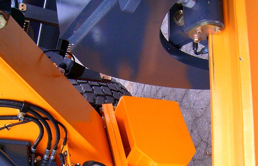
26 AHW_66BH_42BH_JD_GP_T3_GRADE_PRO_EFF_ALL_ _01_024.DOCX Page 26 of 49 FIGURE 13 - Front Post Frame Ready Plate Mounting
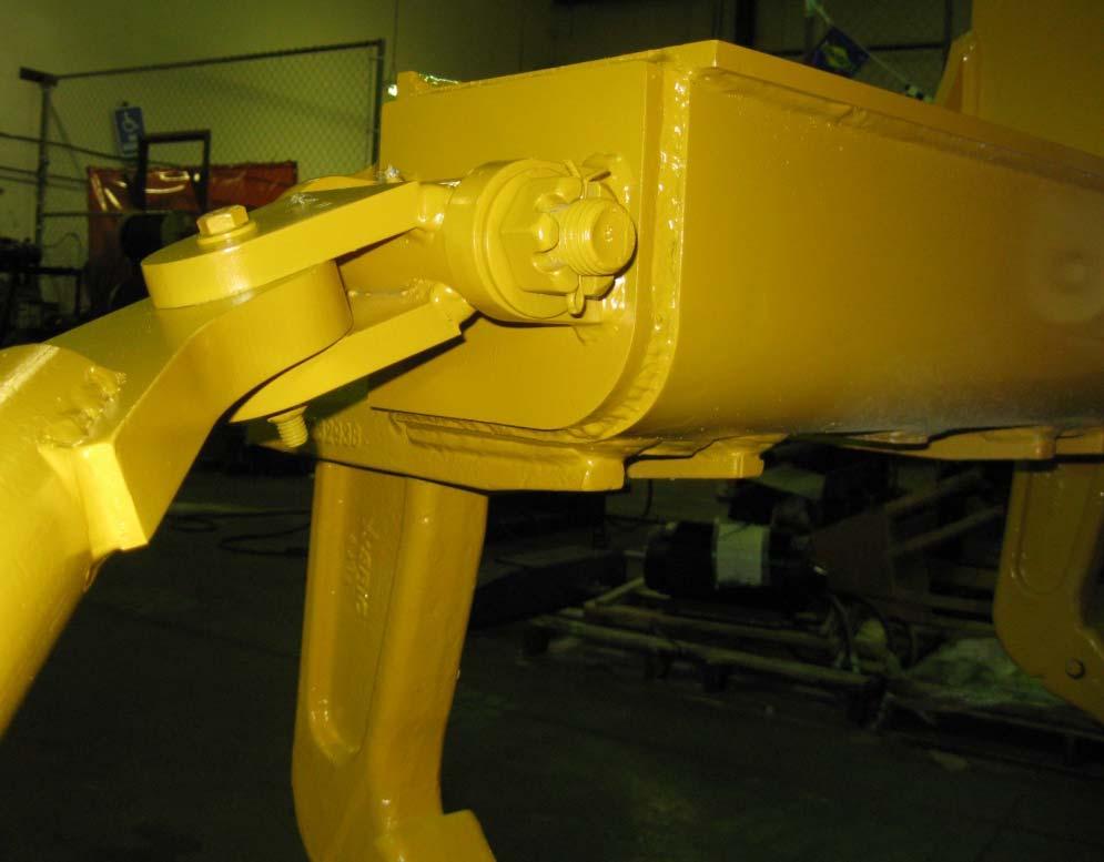
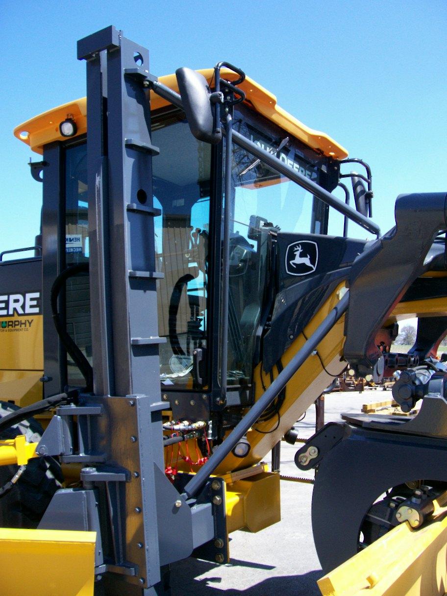
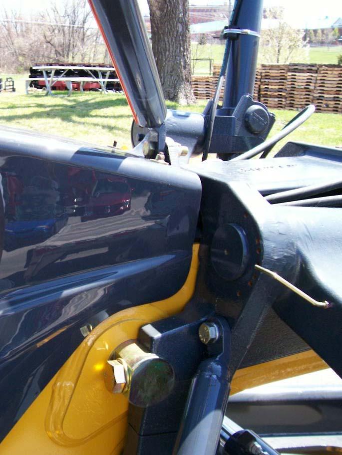
27 AHW_66BH_42BH_JD_GP_T3_GRADE_PRO_EFF_ALL_ _01_024.DOCX Page 27 of 49 FIGURE 14 - Front Post & Attaching Structure Mounting
28 FIGURE 15 - Pipe Braces AHW_66BH_42BH_JD_GP_T3_GRADE_PRO_EFF_ALL_ _01_024.DOCX Page 28 of 49
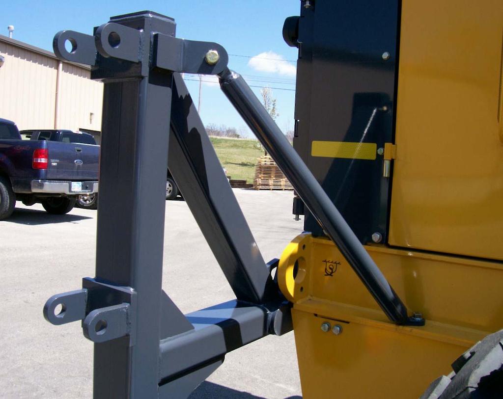
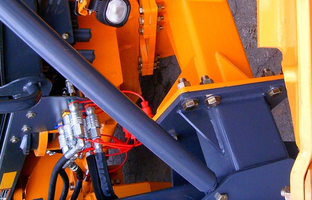
29 FIGURE 16 - Pipe Brace Installation AHW_66BH_42BH_JD_GP_T3_GRADE_PRO_EFF_ALL_ _01_024.DOCX Page 29 of 49


30 FIGURE 17 - Notching of Top Cover AHW_66BH_42BH_JD_GP_T3_GRADE_PRO_EFF_ALL_ _01_024.DOCX Page 30 of 49
31 Hydraulic fittings and hoses Running from Bulkhead plate out to Henke wing (See Figs and Table 7) From bulkhead position 1: Bulkhead Fitting QC Male w/ Cap QC Female w/ Plug Adapter Elbow 45 Deg Hose Adapter In Port V1 on MUDROC Valve Out Port C1 on MUDROC Valve Adapter Hose Elbow To Rod End Port of Wing Lift Cylinder From Bulkhead Position 2: Bulkhead Fitting QC Female w/ Plug QC Male w/ Cap Adapter Elbow 45 Deg Hose Adapter In Port V2 on MUDROC Valve Out Port C2 on MUDROC Valve Adapter Hose Elbow To Barrel End Port of Wing Lift Cylinder From Bulkhead Position 3: Bulkhead Fitting QC Male w/ Cap QC Female w/ Plug Adapter Elbow 45 Deg Hose Elbow To Port T on MUDROC Valve BULKHEAD PLATE From Bulkhead Position 4: Bulkhead Fitting QC Female w/ Plug QC Male w/ Cap Adapter Hose Adapter To Rod End (Rear) Port of Wing Slide Cylinder From Bulkhead Position 5: Bulkhead Fitting QC Male w/ Cap QC Female w/ Plug Adapter Hose Adapter To Barrel End (Front) Port of Wing Slide Cylinder NOTE: All items on this page (except Bulkhead Plate) are included in Kit FIGURE 18 - Hydraulic Schematic, from Bulkhead Plate to Wing AHW_66BH_42BH_JD_GP_T3_GRADE_PRO_EFF_ALL_ _01_024.DOCX 31 of 49 Page
32 7LU 6LU 7LL 6LL From JD Combination Valve T Port (Fig. 18) Tee hose Elbow To Bulkhead Position 3 From Valve Section 7L, Upper Port (7LU): Adapter Hose 80 To Bulkhead Position 2 From Valve Section 6L, Upper Port (6LU): Adapter Hose 80 To Bulkhead Position 4 From Valve Section 6L, Lower Port (6LL): Adapter Hose 80 To Bulkhead Position 5 From Valve Section 7L, Lower Port (7LL): Adapter Hose 80 To Bulkhead Position 1 Note: All hoses & fittings on this page are included in kit (See Table 7). FIGURE 19 - Hydraulic Plumbing, JD GP Valve Workports to Henke Bulkhead Plate (For Grade Pro Graders Only; Wing Valve Sections on LEFT Hand Side.) AHW_66BH_42BH_JD_GP_T3_GRADE_PRO_EFF_ALL_ _01_024.DOCX Page 32 of 49
33 Henke Hoses from JD GP Valve Workports, Left Side to Bulkhead Plate, Right Side. FIGURE 20 - Following Henke Hoses from JD Workports to Bulkhead Plate AHW_66BH_42BH_JD_GP_T3_GRADE_PRO_EFF_ALL_ _01_024.DOCX Page 33 of 49

34 Install Tee in JD Return Line Hose Elbow To Rear to Position 3 On Bulkhead Plate FIGURE 21 - Tie-In to Return Circuit of Grader AHW_66BH_42BH_JD_GP_T3_GRADE_PRO_EFF_ALL_ _01_024.DOCX Page 34 of 49

35 AHW_66BH_42BH_JD_GP_T3_GRADE_PRO_EFF_ALL_ _01_024.DOCX Page 35 of 49 FIGURE 22 - Bulkhead Plate Hydraulics, Inside View From JD Valve Workports From MUDROC Valve

36 AHW_66BH_42BH_JD_GP_T3_GRADE_PRO_EFF_ALL_ _01_024.DOCX Page 36 of 49 FIGURE 23 - Bulkhead Plate Hydraulics, Front View

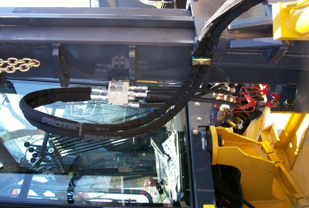
37 FIGURE 24 - Hydraulic Attachment at Bulkhead Plate AHW_66BH_42BH_JD_GP_T3_GRADE_PRO_EFF_ALL_ _01_024.DOCX Page 37 of 49
38 FIGURE 25 - Mounting of MUDROC Valve on Wing Post AHW_66BH_42BH_JD_GP_T3_GRADE_PRO_EFF_ALL_ _01_024.DOCX Page 38 of 49

39 AHW_66BH_42BH_JD_GP_T3_GRADE_PRO_EFF_ALL_ _01_024.DOCX Page 39 of 49 FIGURE 26 - Looping of Hoses on Rear of Wing

40 42 FIGURE 27 - Attachment of Hoses to Clamp on Wing Slide Assembly AHW_66BH_42BH_JD_GP_T3_GRADE_PRO_EFF_ALL_ _01_024.DOCX Page 40 of 49
41 FIGURE 28 - MUDROC Relief Valve Adjustment AHW_66BH_42BH_JD_GP_T3_GRADE_PRO_EFF_ALL_ _01_024.DOCX Page 41 of 49
42 Henke Kit No Qty. Henke Part No. Description Hose Assy., 80", -8 JIC F e/e, Nylon Sleeve Full Length Hose Assy., 26", -8 JIC F e/e Hose Assy., 36", -8 JIC F e/e, Nylon Sleeve Full Length Hose Assy., 98", -8 JIC F e/e, Nylon Sleeve Full Length TABLE 11 - Cylinder Hose Kit for Wing Slide & Lift Cylinders Hose Assy., 48", -8 JIC F x 10 ORFF F Nylon Sleeve Full Length Tee, -10 ORFF M, -10 ORFF Swivel F Run Straight Adapter, -8 JIC M x 8 ORB M Bulkhead Fitting, -8 JIC M x -8 ORB M Elbow, 45, -8 JIC M x 8 JIC Swivel F QC M, ISO 7241-A, 1/2 Body Size, -8 ORB, Poppet QC F, ISO 7241-A, 1/2 Body Size, -8 ORB, Poppet Dust Plug Dust Cap Elbow, 90, -8 JIC M x 10 ORB Adj. M Straight Adapter, -8 JIC M x 10 ORB M Cap, -8 JIC Clamp Pair (must be marked 3087 or 7/8T ) Cover Plate Bolt, 5/16-18 x 1.75, Gr. 2, Zinc Plated Nylon Tie,.30 x 8", UV Black Elbow, 45, -8 JIC M x -8 JIC F Elbow, 90, -8 JIC M x 8 JIC Swivel F Note: All hoses are 1/2 2-wire braid. AHW_66BH_42BH_JD_GP_T3_GRADE_PRO_EFF_ALL_ _01_024.DOCX Page 42 of 49
43 TABLE 12 - Elevating Rear Hose Kit, All JD G Series Graders Henke Kit No Qty. Henke Part No. Description Hose Assy., 3/8 x 40 1/2T, -6 ORFF F x -6 JIC F, Nylon sleeve full length Hose Assy., 3/8 2-wire x 37 1/2T, -6 ORFF F 45 X - 6 JIC F, Nylon Sleeve full length Straight Adapter, -8 ORFF F x -6 ORFF M Straight Adapter, -6 JIC M x -8 ORB M Clamp Pair, 3/8 2-Hose Clamp Cover Plate, 3/8 2-Hose Hex Capscrew, 5/16-18 x 1.25 Gr. 2 Note: All hoses are 1/2 2-wire braid. AHW_66BH_42BH_JD_GP_T3_GRADE_PRO_EFF_ALL_ _01_024.DOCX Page 43 of 49
44 TABLE 13 - Dry Torque Values (Ft.-Lbs.) - for Toplock (All-Metal) or Nylock Nuts ONLY (See Page Notes) Bolt Size (in.) Grade 2 Bolts Grade 5 Bolts Grade 8 Bolts 1/ / / / / / / DO NOT USE THIS TABLE FOR NON-LOCKING NUTS TABLE 14 - Dry Torque Values (Ft.-Lbs.) for Standard Non-Locking Nuts ONLY (See Page Notes) Bolt Size (in.) Grade 2 Bolts Grade 5 Bolts Grade 8 Bolts 1/ / / / / / / DO NOT USE THIS TABLE FOR LOCKING NUTS Page Notes: 1. Dry means plain or zinc-plated fasteners without any lubrication. 2. Fastener Grade Identification: a. Grade 8 bolts are identified by having (6) radial marks on the top of the bolt head. Grade 8 nuts are identified by having radial marks on (2) adjacent corners. b. Grade 5 bolts are identified by having (3) radial marks on the top of the bolt head. Grade 5 nuts are identified by having radial marks on (2) NON-adjacent corners. c. Grade 2 bolts and nuts are identified by having (0) radial marks. AHW_66BH_42BH_JD_GP_T3_GRADE_PRO_EFF_ALL_ _01_024.DOCX Page 44 of 49
45 TABLE 15 - Henke Standard Cutting Edges 6" STEEL 1/2" THICK 5/8" THICK 3/4" THICK 8 STEEL 1/2 THICK 5/8 THICK 3/4 THICK 2FT. Call FT Call 3FT FT Call 4FT FT Call 5FT FT Call FT. Call Call FT FT. Call Call FT Call FT Call Call 9FT FT. Call Call FT FT FT FT FT FT CP 8 1/2 THICK 5/8 THICK 3/4 THICK CP 6 STEEL 1/2 THICK 5/8 THICK 3/4 THICK STEEL 3FT Call Call 3FT Call Call 4FT Call Call 4FT Call Call 10FT Call FT Call CP 10" STEEL 1/2 THICK 5/8 THICK 3/4 THICK 10FT. Call Call CARBIDE 3/4 THICK 3FT.X6 TALL FT.X8 TALL FT.X5 TALL FT.X6 TALL FT.X8 TALL FT.X6 TALL FT Call RUBBER 1 ½ THICK RETAINING STRIP Notes 5&6 X10 Tall CP 8FT FT.X5 TALL Call 9FT FT.X8 TALL FT FT FT FT FT SNOW BASKET THICK X10" Tall CP 8FT FT FT NOTES: 1. For Cutting Edges Not Listed Call Henke Manufacturing at Except as noted, all cutting edges have 1.5" gauge line (distance from top edge to center of holes) 3. "CP" = Center Punched 4. All edges shown are punched for 5/8" bolts. 5. For rubber cutting edges, 6" tall center punched steel edges, Items & may be used to provide proper support behind the rubber edge. 6. Henke's rubber cutting edges feature a minimum tensile strength of 2000 psi and a maximum DIN rating of 150, and last much longer in service than lower quality rubber cutting edges available from some other suppliers. 7.Polyurethane cutting edges also available - call for price and availability. AHW_66BH_42BH_JD_GP_T3_GRADE_PRO_EFF_ALL_ _01_024.DOCX Page 45 of 49
46 TABLE 16 - Henke Standard Cutting Edge Hardware TYPE LENGTH PART NO. USES/NOTES PLOWBOLTS 5/8-11 GRADE 8 CARRIAGE BOLTS 5/8-11 GRADE 8 HEX BOLTS ½ ½ ½ ½ FOR STANDARD CUTTING EDGES AND WEAR GUARDS FOR SOME WRAPAROUND CURB GUARDS (SQUARE HOLES, NOT COUNTER SUNK) RUBBER AND POLY CUTTING EDGES (USE NYLOCK NUTS ONLY) TOPLOCK NUT 5/8-11 GRADE C N/A USE WITH STEEL OR CARBIDE CUTTING EDGES NYLOCK NUT 5/8-11 GRADE 8 N/A USE WITH RUBBER OR POLY CUTTING EDGES AHW_66BH_42BH_JD_GP_T3_GRADE_PRO_EFF_ALL_ _01_024.DOCX Page 46 of 49
47 TABLE 17 - Henke Standard Curb Guards & Wear Guards Wrap-Around Curb Guards, Steel , Left , Right , Reversible Wrap-Around Curb Guards, Chrome-Carbide Weld Deposit on Wrap-Around Corner , Left , Right , Left , Right Wrap-Around Curb Guard + Wear Guard, Chrome-Carbide Weld Deposit on Wrap-Around Corner + on Bottom Wear Edge , Left , Right , Left , Right Bolt-On Curb Guards (Bolts to Outside of End Rib) Bolt-On Guard Assy. Optional spacer (Required for Tripedge applications) Henke Wear Guards and Wear Shoes Wear Guards, Standard Length (9 ), with Chrome-Carbide Weld Deposit (Mount in front of cutting edge) , Reversible , Reversible Wear Guards, Long Length (21 ), with Chrome-Carbide Weld Deposit (Mount in front of cutting edge) , Reversible , Reversible Cast Wear Shoes (Mount behind cutting edge) Wear shoe for 6 cutting edges, or 8 centerpunched edges Wear shoe for 8 cutting edges AHW_66BH_42BH_JD_GP_T3_GRADE_PRO_EFF_ALL_ _01_024.DOCX Page 47 of 49
48 <THIS PAGE IS INTENTIONALLY LEFT BLANK> AHW_66BH_42BH_JD_GP_T3_GRADE_PRO_EFF_ALL_ _01_024.DOCX Page 48 of 49
49 Dealer Warranty Procedure For units delivered within the past 12 months, report any warranty problems needing repair to our Product support department. Please have information ready regarding: 1. Henke unit model and serial number, 2. Model of equipment Henke unit is attached to (prime mover) 3. Description of the problem and any helpful information by the end user. (Photos are always helpful). Measurements or photos may be requested by Henke engineering for any issues regarding prime mover proximity and clearance, or any other unique considerations of fit and adaptability. These may be necessary for a proper repair recommendation and procedure. Henke will respond with a written labor hour allowance for Henke participation on a faxed claim form and will ship any required replacement parts. If necessary, a repair procedure will be included on the claim form. A parts invoice will be generated to confirm shipment of the replacement parts. If defective parts are needed for analysis, Henke will request their return. Any such returned items are to be labeled with the claim number and returned to: Henke Manufacturing Corp. ATTN: Product Support 3070 Wilson Ave. Leavenworth, KS RGA# The dealer should perform repairs as agreed on a dealer warranty repair order. Return the claim form with a copy of the dealer warranty repair order and service report. Credit as agreed will be issued to the dealer upon receipt of the dealer warranty repair order invoice (Pro-forma invoice), and upon receipt, inspection and warranty confirmation of the returned parts if any. Parts & Service Assistance Parts and service assistance is available, Monday through Friday, from 8:00 am to 5:00 pm, CST. Call Our web site, is a quick source for parts pricing, and many common parts diagrams. Parts purchase orders may be faxed in at any time to Faxed orders are encouraged, as they help insure order accuracy and follow up. Include any special instructions, such as drop ship addresses on your order. AHW_66BH_42BH_JD_GP_T3_GRADE_PRO_EFF_ALL_ _01_024.DOCX Page 49 of 49
REMOTE GREASE ASSEMBLY FOR PARALLEL LIFT PLOW
 REMOTE GREASE ASSEMBLY FOR PARALLEL LIFT PLOW HENKE MODEL: REMOTE GREASE ASSEMBLY PARTS AND INSTALLATION MANUAL: # 86382190-01 VERSION 010, DECEMBER 2018 MY SERIAL NUMBER: HENKE MANUFACTURING CORPORATION
POSTLESS ALL HYDRAULIC COMBO WITH TRUCK PLOW
 POSTLESS ALL HYDRAULIC COMBO WITH TRUCK PLOW NOTE: (Does not include Rear Attachment Assemblies, See Separate Product Manual.) HENKE MODEL: SWL, AH, COMBO, PPW, TRK PLW For: Wheel Loaders THIS BOOK HAS
Deere G & GP Series Snow Wing Installation
 Deere G & GP Series Snow Wing Installation Model: Serial Number: Rev. 10/13 Rylind Manufacturing, Inc. 2801 Youngfield St Suite 250 Golden, CO 80401 Offices: 303-979-3548 Fax: 303-979-4730 www.rylind.com
UNDERBODY SCRAPER, FIXED ANGLE
 UNDERBODY SCRAPER, FIXED ANGLE HENKE MODEL: UBS FA,17 FOR: Medium to Heavy Duty Trucks PARTS AND INSTALLATION MANUAL: # 8430302-01 VERSION 010, JUNE 2017 MY SERIAL NUMBER: HENKE MANUFACTURING CORPORATION
RVT SERIES HEAVY DUTY TRIPPING SNOW PLOW
 RVT SERIES HEAVY DUTY TRIPPING SNOW PLOW Model: Serial Number: Rev. 10/13 Rylind Manufacturing, Inc. 2801 Youngfield St Suite 250 Golden, CO 80401 Main Offices: 303-979-3548 Manufacturing Plant: 970-522-2859
RPD SERIES HEAVY AND SEVERE DUTY SNOW PLOW
 RPD SERIES HEAVY AND SEVERE DUTY SNOW PLOW Model: Serial Number: Rev. 01/14 Rylind Manufacturing, Inc. 2801 Youngfield St Suite 250 Golden, CO 80401 Main Offices: 303-979-3548 Manufacturing Plant: 970-522-2859
UNDERBODY SCRAPER, REVERSIBLE, EXTRA HEAVY
 UNDERBODY SCRAPER, REVERSIBLE, EXTRA HEAVY HENKE MODEL: UBS XH FOR: Medium to Heavy Duty Trucks PARTS AND INSTALLATION MANUAL: # 8430102-01 VERSION 016, AUGUST 2018 MY SERIAL NUMBER: HENKE MANUFACTURING
About this Manual. Hazard Notices Used in Manual
 Forward Contents About this Manual Hazard Notices Used in Manual About the QuattroPlow Attachment Plows Attaching the Snow Plow to the Prime Mover Removing the Snow Plow from the Prime Mover Operation
1300 Dozer Owner s Manual & Parts Book
 300 Dozer Owner s Manual & Parts Book Purchase Date Serial Number Model Number Tractor Model Dealer PN: 3-2472 0--2008 Contents Description Page To The Owner 2 Maintenance & Caution 2 Safety Precautions
MDP Multi-Directional Folding-V Snow Plow
 MDP Multi-Directional Folding-V Snow Plow Model Number: Serial Number: Rev. 10/13 Rylind Manufacturing, Inc. 2801 Youngfield St Suite 250 Golden, CO 80401-2263 Business/Sales Offices: 303-979-3548 Manufacturing
SIDE SHIFT HIGH BENCHING WING, REAR- LIFT, SINGLE TELESCOPING PUSHBEAM, FRONT- MOUNT, WITH MOLDBOARD BUMPER
 SIDE SHIFT HIGH BENCHING WING, REAR- LIFT, SINGLE TELESCOPING PUSHBEAM, FRONT- MOUNT, WITH MOLDBOARD BUMPER HENKE MODEL: HBW34, RLSP, FM, SIDE SHIFT, MD BMPR For: Medium to Heavy Duty Trucks PARTS AND
THIS MANUAL INCLUDES. Balderson Style Lift Head With Manual Locking Pins Balderson Style Lift Head With Hydraulic Locking Pins
 PARALLEL LIFT GROUP HENKE MODEL: PLG11, STD and HLP For: John Deere C, D, G, or GP Series Motor Graders THIS MANUAL INCLUDES Balderson Style Lift Head With Manual Locking Pins Balderson Style Lift Head
AG PRO SS Owner s Manual & Parts Book
 AG PRO SS Owner s Manual & Parts Book Purchase Date Serial Number Model Number Tractor Model Dealer PN: 63-19460 SN: 10204276-... Date 1-10-2017 Description Contents Page To The Owner, Maintenance, Safety
4200 & 6200 Owner s Manual & Parts Book
 00 & 00 Owner s Manual & Parts Book Purchase Date Serial Number Model Number Tractor Model PN: - Dealer Date --0 Description Page To The Owner & Maintenance Safety Precautions & Torque Specifications Skid
REVERSIBLE I-PLOW. HENKE MODEL: I-PLOW Medium to Heavy Duty Trucks HENKE MANUFACTURING CORPORATION
 REVERSIBLE I-PLOW HENKE MODEL: I-PLOW Medium to Heavy Duty Trucks PARTS AND INSTALLATION MANUAL: # 8400000-01 VERSION 048, AUGUST 2016 MY SERIAL NUMBER: HENKE MANUFACTURING CORPORATION MANUFACTURERS OF
PARALLEL LIFT PLOW, EXPRESSWAY, SLOTTED TRIP
 PARALLEL LIFT PLOW, EXPRESSWAY, SLOTTED TRIP HENKE MODEL: PLP EXP SLT SIS, PLP EXP AK SLT SIS Medium to Heavy Duty Trucks PARTS AND INSTALLATION MANUAL: # 8400085-01 VERSION 016, JULY 2018 MY SERIAL NUMBER:
FIXED ANGLE, FUNNEL MOLDBOARD, NON-TRIP, HYDRAULIC LAYBACK, OR SHEAR PLOW
 FIXED ANGLE, FUNNEL MOLDBOARD, NON-TRIP, HYDRAULIC LAYBACK, OR SHEAR PLOW HENKE MODEL: OWFA 30-60, NT, HLA, SHEAR FOR: Medium to Heavy Duty Trucks PARTS AND INSTALLATION MANUAL: # 8400016-01 VERSION 012,
450 & Slant Top Owner s Manual & Parts Book
 0 & 0 - Slant Top Owner s Manual & Parts Book Purchase Date Serial Number Model Number Tractor Model PN: - Dealer Date -- Contents Description Page To The Owner & Maintenance Safety Precautions & Torque
ROAD WARRIOR, FULL TRIP PLOW
 ROAD WARRIOR, FULL TRIP PLOW HENKE MODEL: RW CPF FT & RW TT FT FOR: Medium to Heavy Duty Trucks PARTS AND INSTALLATION MANUAL: # 8400105-01 VERSION 020, OCTOBER 2018 MY SERIAL NUMBER: HENKE MANUFACTURING
SkidPro. Hydraulic Snow Blade/Pusher Combo OWNERS/OPERATORS MANUAL. Model Number HSBP.
 SkidPro Hydraulic Snow Blade/Pusher Combo OWNERS/OPERATORS MANUAL Model Number HSBP. Serial Number. Serial Numbers 36, 3600-3603 & 37000 and Greater Manufacture Date 0/0/ Current Phone: 77-37-6 06/0/5
EXPRESSWAY TUBE TABLE, SLOTTED TRIP PLOW, BOBBY PACE RUNNING GEAR
 EXPRESSWAY TUBE TABLE, SLOTTED TRIP PLOW, BOBBY PACE RUNNING GEAR HENKE MODEL: TT, EXP 40-58, SLT, SLL, BPRG Medium to Heavy Duty Trucks PARTS AND INSTALLATION MANUAL: # 8400037-01 VERSION 012, NOVEMBER
8 1/2' and 9 1/2' HDV Snowplow
 TrynEx International, LLC, 31 Ajax Drive, Madison Heights, MI 48071 49 www.snowexproducts.com December 1, 016 Lit. No. 941, Rev. 00 8 1/' and 9 1/' HDV Snowplow Mild Steel Blades 77770, 77780 Stainless
Light Duty Angle Snow Blade
 Light Duty Angle Snow Blade Model Number SBS -LD. Serial Number. Phone: 320-393-7080 1/6/07 Revised 1/1/13 SBS-LD Features of Virnig Mfg. Inc. Light Duty Angle Snow Blade include: 2 bore, 8 3/8 stroke
Post Driver Attachment
 Attachment (Shown with Optional Power Cell Rotator) Models - 600, 850 Safety Instructions This safety alert symbol indicates important safety messages in this manual. When you see this symbol, carefully
TrynEx International, LLC, 531 Ajax Drive, Madison Heights, MI , POWER PLOW Snowplow
 TrynEx International, LLC, 531 Ajax Drive, Madison Heights, MI 48071 49 www.snowexproducts.com January 15, 018 Lit. No. 531, Rev. 04 8100, 8611 POWER PLOW Snowplow Blade Assembly 77750, 77755 Big Box Assembly
EZ Build Assembly and Installation
 Form No. 1-1058 March 2012 EZ Build Assembly and Installation 41500 Lot Pro Diamond Edge Plow with E-72 12V Hydraulic Unit Meyer Products LLC reserves the right, under its continuing product improvement
EZ Build Assembly and Installation
 Form No. 1-1136R May 2016 EZ Build Assembly and Installation 41530 Lot Pro Diamond Edge Plow Standard Operating System with E-73 12V Hydraulic Unit Meyer Products LLC reserves the right, under its continuing
PARTS MANUAL THIS PAGE INTENTIONALLY LEFT BLANK. Ag-Bag International, Ltd. G7000 June Appendix A
 The parts manual is organized into groups, it is designed to make the locating of parts easier. The exploded drawings also show assembly paths. All parts listed are available from your authorized Ag-Bag
TrynEx International, LLC, 531 Ajax Drive, Madison Heights, MI SPEEDWING Snowplow
 TrynEx International, LLC, 53 Ajax Drive, Madison Heights, MI 807-229 www.snowexproducts.com September, 206 Lit. No. 52309, Rev. 03 8600 SPEEDWING Snowplow Blade Assembly 7770 Big Box Assembly 7780 Parts
Blade and Off Truck Kit
 Fisher Engineering 50 Gordon Drive, Rockland, Maine 081 2139 www.fisherplows.com 90750, 90800, 90850, 90900 93800, 93900, 97200, 97300 97250(CH), 97250-1(CH) September 15, 2016 Lit. No. 1776, Rev. 02 Blade
50 Gordon Drive, Rockland, Maine sherplows.com April 15, HS Compact Plow. Blade Assembly 85280/85285 Big Box Assembly 85240
 Fisher Engineering 880/88 0 Gordon Drive, Rockland, Maine 04841-139 www.fi sherplows.com April 1, 017 Lit. No. 883, Rev. 01 HS Compact Plow Blade Assembly 880/88 Big Box Assembly Parts List A DIVISION
JOHN DEERE 9970 COTTON PICKERS
 PARTS CATALOG FOR Mud Hog System II Rear Wheel Drive FOR JOHN DEERE 9970 COTTON PICKERS Mud Hog Model Numbers Tread Center OEM Aftermarket JD40005 JD47655 82, 90, 94, 106 TUTHILL Drive Systems 9098 West
Dozer Blade. Cylinder Bushing Installation. Hydraulic Installation. Model Number DZR. Serial Number. Phone: DZR
 Cylinder Bushing Installation Dozer Blade All 3 cylinders use 4 bushings each. Hydraulic Installation Tilt Cylinder Left Side Angle Cylinder Model Number DZR. Serial Number. Right Side Angle Cylinder Phone:
Blade and Off Truck Kit
 Fisher Engineering 90750, 90800, 90850, 90900, 93800 93900, 97200-1, 97250-2(CH), 97300-1 50 Gordon Drive, Rockland, Maine 081 2139 www.fisherplows.com July 15, 2018 Lit. No. 85302, Rev. 0 Blade and Off
12-20 (V6) - AG PRO PLUS
 - AG PRO PLUS") 12-20 (V6) - AG PRO PLUS Owner s Manual & Parts Book Purchase Date Serial Number Model Number Tractor Model Dealer PN: 6-18817 Date -17-201 Contents Description Page To The Owner, Warning, Maintenance
12-20 (V6) - AG PRO PLUS Owner s Manual & Parts Book Purchase Date Serial Number Model Number Tractor Model Dealer PN: 6-18817 Date -17-201 Contents Description Page To The Owner, Warning, Maintenance
EZ Build Assembly and Installation Lot Pro Plow with E-72 12V Hydraulic Unit
 Form No. -06R June 207 EZ Build Assembly and Installation 4325 Lot Pro Plow with E-72 2V Hydraulic Unit Meyer Products LLC reserves the right, under its continuing product improvement program, to change
Pick Up Broom OWNERS/OPERATORS MANUAL. Model Number. Serial Number. Date of Manufacture. To Serial # Phone:
 Pick Up Broom OWNERS/OPERATORS MANUAL Model Number. Serial Number. Date of Manufacture. To Serial #039 Phone: 77-37-6 //0 Warranty Skid Pro products are warranted to be free from defects, in workmanship,
BUSH HOG LAND MAINTENANCE REPAIR PARTS MANUAL MODELS: RPM & RPM SECTION: 79
 BUSH HOG LAND MAINTENANCE REPAIR S MANUAL MODELS: -0 RPM & -000 RPM SECTION: 9 0 Griffin Ave. Selma, Al. 0 () - () -00 Parts Ordering -00-0- Fax -00-- www.bushhog.com April, 0 BUSH HOG/ LAND MAINTENANCE
DEFENDER Compact Plow
 Western Products, PO Box 4038, Milwaukee, WI 34-938 www.westernplows.com May 1, 017 Lit. No. 88, Rev. 0 DEFENDER Compact Plow Blade Assembly 870/87 Big Box Assembly 860 Parts List A DIVISION OF DOUGLAS
BUSH HOG LAND MAINTENANCE REPAIR PARTS MANUAL MODEL: TD-1100 SECTION: 66
 BUSH HOG LAND MAINTENANCE REPAIR S MANUAL MODEL: TD-00 SECTION: 0 Griffin Ave. Selma, AL 0 () - () -00 Parts Ordering -00-0- Fax -00-- www.bushhog.com BUSH HOG/ LAND MAINTENANCE REPAIR S MANUAL JUNE, 00
KONGSKILDE 9200 DF Vertical Tillage - Assembly/Parts
 KONGSKILDE 9200 DF Vertical Tillage - Assembly/Parts Kongskilde 9200 *Model may not be exactly as shown. Kongskilde reserves the right to make changes to product designs and specifications without notice
TrynEx International, LLC, 531 Ajax Drive, Madison Heights, MI UTV Straight Blade
 TrynEx International, LLC, 53 Ajax Drive, Madison Heights, MI 807-9 www.snowexproducts.com October, 06 Lit. No. 8960, Rev. 00 UTV Straight Blade Blade Assembly 77760 Big Box Assembly 77860 Parts List A
IMPACT UTV Straight Blade
 Western Products, PO Box 5038, Milwaukee, WI 53-9538 www.westernplows.com October, 06 Lit. No. 8959, Rev. 00 IMPACT UTV Straight Blade Blade Assembly 8930 Big Box Assembly 77860 Parts List A DIVISION OF
EZ Build Assembly and Installation
 Form No. 1-1108 April 2014 EZ Build Assembly and Installation 41125 Drive Pro 5.0-6.8 Plow with E-72 12V Hydraulic Unit and 41175 Drive Pro 6.8-7.6 Plow with E-72 12V Hydraulic Unit Meyer Products LLC
REVERSIBLE, FUNNEL, SLOTTED TRIP PLOW
 REVERSIBLE, FUNNEL, SLOTTED TRIP PLOW HENKE MODEL: 30-60 ISR, SLT_SIS17 Medium to Heavy Duty Trucks PARTS AND INSTALLATION MANUAL: # 8400018-01 VERSION 010, OCTOBER 2018 MY SERIAL NUMBER: HENKE MANUFACTURING
7600, 8000, 8600, 9000
 TrynEx International, LLC, 53 Ajax Drive, Madison Heights, MI 4807-2429 www.snowexproducts.com September, 206 Lit. No. 52239, Rev. 04 7600, 8000, 8600, 9000 Heavy Duty Snowplow Blade Assembly 77720, 77725,
DEBRIS BLOWER 2613 BLOWER ASSEMBLY PARTS CATALOG MODEL NO & UP. The TORO Company All Rights Reserved. FORM NO Rev.
 FORM NO. 01-505-0440 Rev. D MODEL NO. 44520-20101 & UP PARTS CATALOG DEBRIS BLOWER 2613 Part 1 61-005-0073 Hitch & Lower Housing 1 2 61-005-0121 Fan Housing 1 3 61-005-0061 Fan Assembly 1 4 01-113-0070
Blade and Off Truck Kit
 Fisher Engineering 0 Gordon Drive, Rockland, Maine 0484 9 www.fisherplows.com 777, 809, 7000 March, 07 Lit. No. 499, Rev. 07 Blade and Off Truck Kit SD Series Snowplow Parts List A DIVISION OF FISHER,
HEAVY DUTY PARTS MANUAL
 HEAVY DUTY PARTS MANUAL REV. 1 RELEASED: 3/19/2013 Table of Contents 1. Complete Unit Pg. 3 2. Heavy Duty Moldboard Pg. 4 3. Heavy Duty Side Panel with Wear Shoe Pg. 5 4. Installation of Side Panel to
BUSH HOG LAND MAINTENANCE REPAIR PARTS MANUAL MODEL: 405 / 406 SECTION: 17
 BUSH HOG LAND MAINTENANCE REPAIR S MANUAL MODEL: 0 / 0 SECTION: 0 Griffin Ave. Selma, AL 0 () - () -00 Parts Ordering -00-0- Fax -00-- www.bushhog.com BUSH HOG/ LAND MAINTENANCE REPAIR S MANUAL SEPTEMBER,
SERVICE PARTS MANUAL
 SERVICE PARTS MANUAL HTV SERIES SNOW PLOW FOR SERIAL NUMBERS AFTER HTV0000 Sno-Way, Down Pressure and EIS are registered trademarks of Sno-Way International, Inc. ProControl, MegaBlade, V-Wing, E-Z Switch,
VALVE AND PLUMBING KIT NEW HOLLAND 7310 LOADER NEW HOLLAND TRACTORS
 ASSEMBLY MANUAL Keep With Operator s Manual VALVE AND PLUMBING KIT NEW HOLLAND 73 LOADER NEW HOLLAND TRACTORS MODEL 2WD FWA LESS CAB WITH CAB TT55 X X X TT75 X X X Valve and plumbing kit can be installed
MIDWEIGHT, PRO PLOW Series 2 and POLY PRO PLOW Series 2 Snowplow
 Western Products, PO Box 45038, Milwaukee, WI 534-9538 www.westernplows.com May 1, 014 Lit. No. 43186, Rev. 01 MIDWEIGHT, PRO PLOW Series and POLY PRO PLOW Series Snowplow Poly Blade Assemblies 7400, 7450,
GrabTec. Farm Grapple OWNER S MANUAL. GF and GFD Models
 Farm Grapple OWNER S MANUAL GF and GFD Models Grabtec Inc May 2014 Install Center/Shipping/Receiving: 1242 Arizona Ave Larchwood, IA 1241 (888) 87-892 (712) 477-267 PREFACE This manual describes the installation,
SERVICE PARTS MANUAL
 SERVICE PARTS MANUAL SERIES AND R SNOW PLOWS WITH EIS PLOW LIGHT HARNESS CONNECTIONS FOR GRAVITY HYDRAULICS WITH SERIAL NUMBERS BEFORE G000 WITH SERIAL NUMBERS AFTER G00000 FOR DOWN PRESSURE HYDRAULICS
530B ECOLO-TIGER MULCH CHISEL WARNING AND TAILIGHT KIT ECOLO-TIGER 530B
 04-01 WARNING AND TAILIGHT KIT ECOLO-TIGER 530B 04-01 WARNING AND TAILIGHT KIT ECOLO-TIGER 530B 2 27602311 1 HARNESS, WIRE, Front 3 27602221 1 HARNESS, WIRE, Rear (530B) 4 27602202 2 LIGHT ASSY., Red 5
PARTS MANUAL. HD4SR and 12SR Auto Align Bale Skoop to 2017 K
 PARTS MANUAL 1998 to 2017 HD4SR and 12SR Auto Align Bale Skoop K34991-04 Table of Contents Section 1: Parts Breakdown...1-1 Bale Skoop Final Assembly... 1-2 Loader Assembly... 1-4 12SR - Grab Hook Assembly
TWIN ROTARY RAKE PARTS BOOK MODEL
 TWIN ROTARY RAKE PARTS BOOK MODEL 2650 17.01135 This parts book is furnished for your convenience only. All parts must be purchased through an authorized dealer. Call us for a dealer near you. Issue Date:
PARTS BOOK CATALOG IMPLEMENT ASSEMBLIES STANDARD BOOM 3PT HITCH MOUNT
 PARTS BOOK CATALOG IMPLEMENT ASSEMBLIES STANDARD BOOM 3PT HITCH MOUNT DIAMOND MOWERS, Inc. 350 E 60 th St. North Sioux Falls, SD 57104 FOR WARRANTY CALL DIAMOND MOWERS DIRECT: 888-960-0364 OUR TECHNICIANS
320 Series Models 325, 326, 327
 0 Series Models,, ROTARY MOWER Published 0/ PARTS MANUAL SECTION An Operator s Manual was shipped with the equipment. The Operator s Manual is an integral part of the safe operation of this machine and
VALVE AND PLUMBING KIT 2408TL LOADER AGCO & MASSEY FERGUSON TRACTORS
 ASSEMBLY MANUAL Keep With Operator s Manual VALVE AND PLUMBING KIT 2408TL LOADER AGCO & MASSEY FERGUSON TRACTORS AGCO MASSEY FERGUSON CAB ROPS ST34A 1533 X ST41A 1540 N/A X TRACTOR AND VALVE KIT GENERAL
PRODIGY & PRO PLUS Skid Steer Snowplows
 Western Products, PO Box 245038, Milwaukee, WI 53224-9538 www.westernplows.com April 1, 2013 Lit. No. 57996, Rev. 01 PRODIGY & PRO PLUS Skid Steer Snowplows PRODIGY Blade Assembly 57700 PRO PLUS Blade
Drive End Bracket & Bearing. Drive End Bracket. Tandem Axle # #865733
 Drive End Bracket & Bearing #865089 1 06409700 1" Lock Collar 2 865733 Drive Bracket w/ Bearing 3 310037 End Drive Shaft Drive End Bracket #865733 1 03003100 Bearing 1" w/snap Ring 2 957795 Drive End Bracket
INSTALLATION & OWNER S MANUAL
 INSTALLATION & OWNER S MANUAL V5008 Kubota RTV 72 Snow Blade The contents of this envelope are the property of the owner. Be sure to leave with the owner when installation is complete. IMPORTANT: Please
CITY OF ROCK ISLAND S P E C I F I C A T I O N S
 CITY OF ROCK ISLAND S P E C I F I C A T I O N S It is the intent of the City of Rock Island to receive bids on fourteen (14) snow plows. The proposed plows will be used by the Public Works Departments
HYDRAULIC VALVE KIT McCORMICK MC90, MC100, & MC115 TRACTORS
 ASSEMBLY MANUAL 2-7367 Keep With Operator s Manual HYDRAULIC VALVE KIT McCORMICK MC90, MC100, & MC115 TRACTORS Note: Requires McCormick power beyond manifold and joystick to complete. Figure 2 VALVE INSTALLATION
BH200 SERIES ROTARY CUTTER
 Revised Published01/19 BH200 SERIES ROTARY CUTTER PARTS MANUAL SECTION 121 MODELS BH215, BH216, BH217 An Operator s Manual was shipped with the equipment. The Operator s Manual is an integral part of the
TrynEx International, LLC, 531 Ajax Drive, Madison Heights, MI , Regular Duty Snowplow
 TrynEx International, LLC, 3 Ajax Drive, Madison Heights, MI 807- www.snowexproducts.com September, 06 Lit. No. 3, Rev. 0 7600, 8000 Regular Duty Snowplow Blade Assembly 7770, 777 Big Box Assembly 7780
3509 & 3511 BACKHOE 3-POINT HITCH / CATEGORY II PARTS MANUAL. Part Number: MODEL NUMBER: Rev. 4
 509 & 5 BACKHOE -POINT HITCH / CATEGORY II PARTS MANUAL SERIAL NUMBER: Manual Number: PM609 Part Number: 5509 MODEL NUMBER: Rev. 800-56-00 I www.paladinlcg.com 50 Gay Street, Delhi, IA 5, United States
SNOW PLOWS OPERATION & MAINTENANCE MANUAL
 SNOW PLOWS OPERATION & MAINTENANCE MANUAL INTRODUCTION TABLE OF CONTENTS Page PLEASE READ ALWAYS INSIST ON GENUINE AIR-FLO PARTS & ASSESSORIES QUICK-SILVER SNOW PLOW Please get to know your Quick-Silver
M MARCH 2002 Parts Manual Contains:
 M-0- MARCH 00 Parts Manual Contains: Warranty Information Warnings Parts Ordering Information Exploded View Parts Breakdowns LIFT CORP. 9 Slauson Ave. Santa Fe Springs, CA. 900 CUSTOMER SERVICE: TELEPHONE
RITE WAY MFG. CO. LTD. P.O.
 CO. LTD. P.O. Box 328 Imperial, Saskatchewan Canada, S0G 2J0 Ph: (306) 963-280 Fax: (306) 963-2660 Web Site: www.ritewaymfg.com E-mail: info@ritewaymfg.com Table of Contents SPECIFICATIONS... WARNING...2
Assembly & Installation Instructions
 TM P R O D U C T S Assembly & Installation Instructions FOR 28 SERIES SNOWPLOW PIVOT ASSEMBLY AND FLOAT LIMITER 99103000 FOR SERIAL NUMBERS 28D100000 TO 28D100770 97100552A 1. THINK SAFETY, ALWAYS WEAR
FIXED ANGLE, SPRING IN SPRING, SLOTTED TRIP, FUNNEL PLOW
 FIXED ANGLE, SPRING IN SPRING, SLOTTED TRIP, FUNNEL PLOW HENKE MODEL: OWFA SLT_SIS17 FOR: Medium to Heavy Duty Trucks PARTS AND INSTALLATION MANUAL: # 8400017-01 VERSION 011, NOVEMBER 2018 MY SERIAL NUMBER:
SERVICE PARTS MANUAL
 SERVICE PARTS MANUAL HD, R & THD SERIES SNOW PLOWS WITH EIS PLOW LIGHT HARNESS CONNECTIONS FOR GRAVITY HYDRAULICS WITH SERIAL NUMBER AFTER: HDG00000 FOR DOWN PRESSURE HYDRAULICS WITH SERIAL NUMBERS AFTER:
Mulching and Finishing Mowers MP and FP
 Mulching and Finishing Mowers MP and FP Parts Manual Locke Turf 0 Highway E, Opp, Alabama, () -00 Transport Wheel, Tire & Spindle MP and FP ALPHABETICAL INDEX CONTENTS PAGE 00 Hydraulic Cylinder (Rear)
PARTS BOOK PARTS BOOK CATALOG
 PARTS BOOK PARTS BOOK CATALOG BOOM FLEXWING MOWER MOWERS HEADS ROTARY 15 CUT FLAIL DRAWBAR SAW HEAD MOUNT DITCHER DIAMOND MOWERS, LLC 350 E 60 th St. North Sioux Falls, SD 57104 FOR WARRANTY CALL DIAMOND
PARTS CATALOG FOR. Mud Hog Rear Wheel Drive FOR. MF 9540/9550/9560, CAT 540C/550C/560C, Gleaner A540/A560, Fendt 6450R/9480R COMBINES
 PARTS CATALOG FOR Mud Hog Rear Wheel Drive FOR MF 9540/9550/9560, CAT 540C/550C/560C, Gleaner A540/A560, Fendt 6450R/9480R COMBINES Mud Hog Model Number: AG9896 A Product of Tuthill Drive Systems P.O.
HYDROBURST HB3038, HB5058, HB80, HB125
 TM HYDROBURST HB3038, HB5058, HB80, HB125 Parts Manual HYDROBURST HB3038, HB5058, HB80 & HB125 s/n Part No. PM1251 INTRODUCTION HOW TO USE THE MANUAL This manual contains illustrations and parts list of
Blade and Off-Truck Kit
 Fisher Engineering 50 Gordon Drive, Rockland, Maine 0484- www.fi sherplows.com 4800, 480, 4850 80, 850, 8800 September 5, 08 Lit. No. 8550, Rev. 0 Blade and Off-Truck Kit XLS Snowplow Parts List Snowplows
BUSH HOG LAND MAINTENANCE REPAIR PARTS MANUAL MODEL: 280 SERIES SECTION: 59
 BUSH HOG LAND MAINTENANCE REPAIR S MANUAL MODEL: 0 SERIES SECTION: 0 Griffin Ave. Selma, AL 0 () () 00 Parts Ordering 00 0 Fax 00 www.bushhog.com BUSH HOG/ LAND MAINTENANCE REPAIR S MANUAL October, 0 0
TrynEx International, LLC, 531 Ajax Drive, Madison Heights, MI , Light Truck Snowplow
 TrynEx International, LLC, 3 Ajax Drive, Madison Heights, MI 407 49 www.snowexproducts.com December, 06 Lit. No. 947, Rev. 00 600, 700 Light Truck Snowplow Blade Assembly 77700, 7770 Big Box Assembly 7700-
Model 1550 Series In-Row Ripper Parts Manual
 Model 1550 Series In-Row Ripper Parts Manual LANDOLL CORPORATION 1900 North Street Marysville, Kansas 66508 (785) 562-5381 800-428-5655 ~ WWW.LANDOLL.COM F-299-0111 01/2011 Table of Contents 1 Instructions
MIDWEIGHT, PRO-PLOW Series 2 and POLY PRO-PLOW Series 2 Snowplow
 Western Products, PO Box 45038, Milwaukee, WI 534-9538 www.westernplows.com June 15, 018 Lit. No. 94111, Rev. 01 MIDWEIGHT, PRO-PLOW Series and POLY PRO-PLOW Series Snowplow Poly Blade Assemblies 7400,
25 Horsepower Hydrostatic Zero-Turn Commercial Riding Mower
 MMZ 2, 260 2 Horsepower Hydrostatic Zero-Turn Commercial Riding Mower ILLUSTRATED PARTS LIST " Float Cutter Deck - Figure 1 3 1 27 32 17 6 1 11 31 36 3 19 7 23 1 33 38 18 37 22 3 20 2 10 2 12 21 30 39
EZ Build Assembly and Installation
 Form No. 1-1109 April 2014 EZ Build Assembly and Installation 41475 Road Pro Plow GTT with E-72 12V Hydraulic Unit Meyer Products LLC reserves the right, under its continuing product improvement program,
SERVICE PARTS MANUAL
 SERVICE PARTS MANUAL HD, R & THD SERIES SNOW PLOWS WITH EIS PLOW LIGHT HARNESS CONNECTIONS FOR GRAVITY HYDRAULICS WITH SERIAL NUMBER AFTER: HDG00000 FOR DOWN PRESSURE HYDRAULICS WITH SERIAL NUMBERS AFTER:
2720/12720 PARTS MANUAL 72A SECTION FLEX WING ROTARY MOWER
 0/0 This Manual applies to models 0 and 0 that use a blade pan which measures. blade hole center to blade hole center. Also blades measure 8. from hole center to blade tip. See Section if these dimensions
SERVICE PARTS MANUAL
 SERVICE PARTS MANUAL 28V SERIES SNOW PLOWS FOR PLOW SERIAL NUMBERS AFTER 28VG100000 28VD100000 07 Sno-Way International 9710097F TABLE OF CONTENTS Page PARTS LIST INTRODUCTION... 2 POWER PACK FRAME...
PARTS BOOK CATALOG IMPLEMENT ASSEMBLIES STANDARD BOOM 3PT HITCH MOUNT
 PARTS BOOK CATALOG IMPLEMENT ASSEMBLIES STANDARD BOOM 3PT HITCH MOUNT DIAMOND MOWERS, Inc. 350 E 60 th St. North Sioux Falls, SD 57104 FOR WARRANTY CALL DIAMOND MOWERS DIRECT: 888-960-0364 OUR TECHNICIANS
SPEEDWING Snowplow. Model 8600SW Blade Crate Assembly Big Box Assembly Parts List
 November 15, 013 Lit. No. 305, Rev. 0 SPEEDWING Snowplow Model 8600SW Blade Crate Assembly 5751 Big Box Assembly 5756 Parts List This Parts List is for BLIZZARD SPEEDWING snowplows with serial numbers
! CAUTION! ! WARNING!
 Assembly Instructions! 24- and 30-Foot, No-Till Flat Fold Marker Option Used with: 2N-2410 and 2N-3010 Drills 2N-2420 and 2N-3020 Drills When you see this symbol, the subsequent instructions and warnings
Trailer Sprayer PARTS BOOK MODEL 500BW B
 Trailer Sprayer PARTS BOOK MODEL 500BW 07.09225B This parts book is furnished for your convenience only. All parts must be purchased through an authorized dealer. Call us for a dealer near Issue Date:
WX540 SERIES Trailer Log Splitter Parts Manual Starting with S/N s WX540L: 2E9US1115ES to 2E9US1115ES WX540: to
 EMB Manufacturing Inc. 4144 Boomer Line St. Clements, On N0B 2M0 Canada Ph: (519) 699-9283 Fax: (519) 699-4146 www.wallensteinequipment.com WX540 SERIES Trailer Log Splitter Parts Manual Starting with
! CAUTION! ! WARNING!
 Assembly Instructions! 3N-3010P, No-Till Flat Fold Marker Option Used with: 3N-3010P Drills When you see this symbol, the subsequent instructions and warnings are serious - follow without exception. Your
Blade and Off Truck Kit HC Series Snowplows
 Fisher Engineering 50 Gordon Drive, Rockland, Maine 04841 139 www.fisherplows.com 79000, 7900 (CH), 7950, 79350 September 1, 018 Lit. No. 77137, Rev. 03 Blade and Off Truck Kit HC Series Snowplows Including
CRAIG MANUFACTURING LTD. 96 McLean Ave. Hartland, New Brunswick CANADA E7P 2K5
 SNOW WING 301 301-10FM Hydraulic Wing Assembly owners manual. Read before operating. Important safety and operation instructions inside. CRAIG MANUFACTURING LTD. 96 McLean Ave. Hartland, New Brunswick
Parts Manual PZ Please read the operator manual carefully and make sure you understand the instructions before using the machine.
 Parts Manual PZ 60 967 045601-00 Please read the operator manual carefully and make sure you understand the instructions before using the machine. When you need spare parts or support in service questions,
MIDWEIGHT, PRO PLOW Series 2 and POLY PRO PLOW Series 2 Snowplow
 Western Products, PO Box 45038, Milwaukee, WI 534-9538 www.westernplows.com May 1, 014 Lit. No. 49584, Rev. 10 MIDWEIGHT, PRO PLOW Series and POLY PRO PLOW Series Snowplow Poly Blade Assemblies 7400, 7450,
ALL PLANT & MIN TILL DRILL
 4000 SERIES ALL PLANT & MIN TILL DRILL OWNER S MANUAL ADDENDUM OPERATION MAINTENANCE REPAIR PARTS #608869 (03-08) 2 Table of Contents Precision Planting Metering System 5-9 Precision Planting Introduction