REMOTE GREASE ASSEMBLY FOR PARALLEL LIFT PLOW
|
|
|
- Clarissa Atkinson
- 5 years ago
- Views:
Transcription

 682-9000Fax: (913) 682-0300 www.henkemfg.com, parts@henkemfg.")
1 REMOTE GREASE ASSEMBLY FOR PARALLEL LIFT PLOW HENKE MODEL: REMOTE GREASE ASSEMBLY PARTS AND INSTALLATION MANUAL: # VERSION 010, DECEMBER 2018 MY SERIAL NUMBER: HENKE MANUFACTURING CORPORATION MANUFACTURERS OF SNOW REMOVAL EQUIPMENT FOR OVER 100 YEARS 3070 WILSON AVE.LEAVENWORTH, KS Phone:(913) Fax: (913) parts@henkemfg.com PLP_REMOTE_GREASE_ASY_EFF_ALL_ _01_010
2 <<THIS PAGE IS INTENTIONALLY LEFT BLANK>> PLP_REMOTE_GREASE_ASY_EFF_ALL_ _01_010 Page 2 of 28
3 Introduction Thank you for your purchase of a HENKE Remote Grease Assembly For Parallel Lift Plow (Remote Grease Assembly). This Parts and Installation Manual should be read in its entirety, including the safety section, before installation, operation, or maintenance is performed to minimize installation and operation problems. In addition to their field-proven standard units, Henke designs and manufactures snow fighting equipment to meet specific customer requirements. The field hardware required to install your new Henke product is listed in tables in the parts section of this book. Be sure to check that all parts listed in this document were shipped with your Plow (either attached or loose). In the unlikely situation that parts are missing please contact Henke Manufacturing at (913) or service@henkemfg.com before continuing the installation. PLP_REMOTE_GREASE_ASY_EFF_ALL_ _01_010 Page 3 of 28
4 Contact Your Local Dealer For Parts & Service Henke's Dealer Network is a key component in providing our customers with the quickest most efficient access to Henke's Parts and Technical Service teams. For Parts Replacement, Technical Service, & Customer Support Inquiries, please contact your local Henke dealer first. Find your dealer using our website Dealer Locator: If you do not have a local dealer, contact Henke directly, as listed below. Replacement Parts Henke's Parts team will assist in parts replacement and preventative parts stocking program. Dealers and individual owners without a local dealer can contact us via , website, or phone. parts@henkemfg.com x3 This will direct your inquiry to the entire Parts team, insuring the most prompt attention possible. All inquiries are processed in the order they are received. NOTE: We can prepare a personalized wear parts recommendation and optionally include your seasonal purchasing summary. Just ask. Call Henke's Technical Service team in the unlikely event that your order is missing parts. PLP_REMOTE_GREASE_ASY_EFF_ALL_ _01_010 Page 4 of 28
5 Technical Service & Customer Support Inquiries Henke Technical Service can assist in optimizing your Henke equipment, and increasing up-time by providing technical guidance and support for issues as they occur. Dealers and individual owners without a local dealer can contact us via , website, or phone. service@henkemfg.com x6 This will direct your inquiry to the entire Tech Service team, insuring the most prompt attention possible. All inquiries are processed in the order they are received. We truly appreciate your business. Henke Parts and Technical Service Teams Is This Your Product Manual? We strongly recommend verifying your product s serial number and product manual number and revision with Henke s Parts Department before you order parts. Henke prides itself on service and support of all of our products including current, legacy, custom, and standard designs. Therefore, many of Henke products appear similar, but are different enough to justify having separate part manuals. Product manuals shown on product pages of the Henke website are only for standard, current production products. Product manuals may be updated at anytime. PLP_REMOTE_GREASE_ASY_EFF_ALL_ _01_010 Page 5 of 28
6 Table of Contents Introduction 3 Contact Your Local Dealer For Parts & Service 4 Replacement Parts 4 Technical Service & Customer Support Inquiries 5 Is this your product manual? 5 CHAPTER 2: Parts And Assemblies 7 Optional Remote Grease Part Assemblies 8 Getting Started, And Taking Basic Precautions 10 Optional Remote Grease System Installation 11 PLP Remote Grease Assembly, Installation Instructions 11 CHAPTER 3: Maintenance 21 In Season Maintenance 22 End Of Season Maintenance 23 Torque Table Mild Steel 24 CHAPTER 4: Warranty & Dealer Procedure 25 HENKE LIMITED WARRANTY 26 Dealer Warranty Procedure 28 PLP_REMOTE_GREASE_ASY_EFF_ALL_ _01_010 Page 6 of 28
7 CHAPTER 2: PARTS AND ASSEMBLIES PLEASE READ ENTIRE BOOK BEFORE INSTALLATION, OPERATION, OR MAINTENANCE. PLP_REMOTE_GREASE_ASY_EFF_ALL_ _01_010 Page 7 of 28
8 Optional Remote Grease Part Assemblies Table 2-1:Optional PLP Remote Grease Part Descriptions Quantity Description " Bulkhead, Remote Grease " Bulkhead, Remote Grease, 12 Port Holes " Bulkhead, Remote Grease, 10 Port Holes Hex Capscrew, 3/8-16 x 1, GR Nylock Nut, 3/8-16 GR Double Hose Clamp Grease Fitting, Straight, 1/8 NPT Vinyl Hose Clamp, 1-7/8 ID, 1-Hose /4-28 MALE X 1/8 NPSF JIC to Pipe Elbow JIC Swivel Elbow JIC to Pipe Elbow JIC to Pipe Bulkhead with Lock nut Hydraulic Hose, 1/8 100R7 X 28"T, -4 JIC F x -4 JIC F, Full Nylon Hose Length Hydraulic Hose, 1/8 100R7 X 40"T, -4 JIC F x -4 JIC F, Full Nylon Hose Length Hydraulic Hose, 1/8 100R7 X 52"T, -4 JIC F x -4 JIC F, Full Nylon Hose Length Hydraulic Hose, 1/8 100R7 X 64"T, -4 JIC F x -4 JIC F, Full Nylon Hose Length Black Cable Tie, 14" UV Pin, 3 x x 3-Hole, Center Pin Pin, 1.25 x 6.44 x Hole * Pin 3 x Hole, with * Pins 1.25 x 6.44 x Hole, with Hydraulic Fitting Pin, 1 x 2.25 x 1-Hole, Cylinder Knuckle Pins Pin, 1.25 x 4.69 x Hole, Rear Arm Pins * NOTE: Factory replaces non-grease-able pins with remote grease pins during factory install. PLP_REMOTE_GREASE_ASY_EFF_ALL_ _01_010 Page 8 of 28
9 Table 2-1:Comparison Of Optional PLP Remote Grease Assemblies Assembly No. Installed By Description Factory FACTORY INSTALL, Grease Assembly, Includes all hoses Includes a negative Quantity of Center Pins For Inventory Factory FACTORY INSTALL, Same as , except omits outer roller grease lines Customer FIELD RETROFIT, version of rear arm and lift cylinder pin replacements Shipments BEFORE Customer FIELD RETROFIT, version of Shipments AFTER (Already received grease-able arm and cylinder pins) Customer FIELD RETROFIT, Same as , except omits 2 outer roller grease lines Shipments BEFORE Customer FIELD RETROFIT, Same as , except omits 2 outer roller grease lines Shipments AFTER (Already received grease-able arm and cylinder pins) Table 2-1:Optional PLP Remote Grease Assembly Quantities Part No. Quantity Factory Install Factory Install Parts Kits Parts Kits Parts Kits Parts Kits * -1* * -2* * NOTE: Factory replaces non-grease-able pins with remote grease pins during factory install. PLP_REMOTE_GREASE_ASY_EFF_ALL_ _01_010 Page 9 of 28
10 Getting Started, And Taking Basic Precautions STEP 1: STEP 2: STEP 3: STEP 4: STEP 5: PLEASE READ ENTIRE BOOK BEFORE INSTALLATION, OPERATION, OR MAINTENANCE. Verify you have all necessary parts and equipment for your Henke installation. Park the truck on a flat, level surface. Chock the tires. Refer to truck owner s manual for information about chocking the tires. Disconnect the battery when welding any items that are attached to the truck. Never weld items to a truck frame. Always use bolts. NOTE: Attempt to use existing bolt holes for attachment where available (assuming they are located properly and of the proper size). It is generally not advisable to bolt through the upper and lower flanges of the truck frame. When bolting a hitch to the front of the frame rails, however, bolting through the upper or lower flanges is typically not a problem, because the frame sees very little loading in this area. When bolting through the side (web) of the truck frame, avoid bolting extremely close to the upper and lower flanges. This rule can be relaxed for areas at the very front of the frame. When welds are called out in the instructions, use continuous 3/8 minimum fillet welds unless otherwise specified or appropriate. Fully torque all appropriate hardware before using Henke products. See torque table on page 1. SEE SEPARATE TABLE FOR APPROPRIATE TORQUE VALUES All References To "Left" And "Right" Are From The Driver's Perspective. PLP_REMOTE_GREASE_ASY_EFF_ALL_ _01_010 Page 10 of 28
11 Optional Remote Grease System Installation PLP Remote Grease Assembly, Installation Instructions Getting Started STEP 1: Read Getting Started And Taking Basic Precautions before continuing page 10. Verify Parts Received STEP 2: Verify you have received all parts from the appropriate assembly option listed on page 8. NOTES: To simplify the following instructions, the matching bulkhead hole, fitting(s), hose, and port hole all share the same ID number within the instructions. Example: Bulkhead hole 1, connects to hose 1, then to fitting(s) 1, and ends at port 1. Image schematics and tables are provided for visual guidance. Fitting orientation is important for best fit and function. See orientation notes listed in Table 2-2: page 17. PLP_REMOTE_GREASE_ASY_EFF_ALL_ _01_010 Page 11 of 28
12 STEP 1: Before Paint: Weld bulkhead onto pushframe in the location shown in Figure 2-1: using the specified weld pattern. STEP 2: Fully weld head of (5) bolts to plow in specified locations shown in Figure 2-1:. Figure 2-1:Welding Bolts And Bulkhead To Pushframe PLP_REMOTE_GREASE_ASY_EFF_ALL_ _01_010 Page 12 of 28
13 STEP 3: Weld bulkhead on the plow portion hitch in the location shown in Figure 2-2: page 13. Figure 2-2:Welding Bulkhead To Plow Portion Hitch STEP 4: Fully weld head of (2) bolts to plow in specified locations shown in Figure 2-3:. Figure 2-3:Welding Bolts To Upper Arm PLP_REMOTE_GREASE_ASY_EFF_ALL_ _01_010 Page 13 of 28
14 STEP 5: Replace all required pins if using assembly or STEP 6: Remove grease zerks from all pins, a total of (18) zerks. See locations (excluding 7 & 9) noted in Figure 2-5: page 15 and Figure 2-6: page 16. STEP 7: Grind and Paint welds as needed. PLP_REMOTE_GREASE_ASY_EFF_ALL_ _01_010 Page 14 of 28

15 After Paint: STEP 1: Install (20) with (20) into all open bulkhead locations, oriented so the hoses will connect as shown in Figure 2-4: page 15. Figure 2-4:Bulkhead Hole Location ID And Bulkhead Fitting Orientation NOTE: Top, Bottom, Left, and Right in this image are relative to the image, not relative to the driver. Figure 2-5:Plow Portion Hitch Port Locations PLP_REMOTE_GREASE_ASY_EFF_ALL_ _01_010 Page 15 of 28
16 Figure 2-6:Pushframe Port Locations PLP_REMOTE_GREASE_ASY_EFF_ALL_ _01_010 Page 16 of 28
17 STEP 2: Fitting ID Install Fittings and rotate them in the direction listed in Table 2-2: page 17 and shown in Figure 2-5: page 15 and Figure 2-6: page 16. Fitting Item Number Table 2-2:Fitting Identification And Matching Port Location Fitting Description Port Location Orientation Notes 1* JIC to Pipe Elbow 90 1 Up at 45 toward plow JIC to Pipe Elbow 90 2 Pointing outward JIC to Pipe Elbow 90 3 Pointing outward & /4-28 MALE X 1/8 NPSF & JIC to Pipe Elbow 90 4 Pointing downward & /4-28 MALE X 1/8 NPSF & JIC to Pipe Elbow 90 5 Pointing upward & /4-28 MALE X 1/8 NPSF & JIC to Pipe Elbow 45 6 Pointing left JIC to Pipe Elbow 90, 3/8-18 NPT 7 MUST Point left & /4-28 MALE X 1/8 NPSF & JIC to Pipe Elbow 45 8 Pointing left JIC to Pipe Elbow 90, 3/8-18 NPT 9 MUST Point left 10* JIC to Pipe Elbow Up at 45 toward plow JIC to Pipe Elbow Pointing outward JIC to Pipe Elbow Pointing outward JIC to Pipe Elbow Pointing up and left JIC to Pipe Elbow Pointing up and right JIC to Pipe Elbow Pointing forward JIC to Pipe Elbow Pointing forward JIC to Pipe Elbow Pointing right JIC to Pipe Elbow Pointing left JIC to Pipe Elbow Parallel to arm tube JIC to Pipe Elbow Parallel to arm tube * NOTE: , , and omit ports 1 & 10. PLP_REMOTE_GREASE_ASY_EFF_ALL_ _01_010 Page 17 of 28
18 STEP 3: STEP 4: Install the hoses into similarly numbered bulkhead hole. Hose identification is listed in Table 2-3: page 18. Connect the loose end of hoses to the simliarly numbered fitting listed in Table 2-3: page 18. Table 2-3:Hose Identification And Routing Chart NOTE: All hoses are 1/8" 100R7, -04 JIC Female, End To End, with Full Nylon Hose Sleeve. Hose ID Hose Item Number Total Hose Length Routes To Fitting # 1* " " " " " " " " " 9 10* " " " " " " " " " " " 20 * NOTE: , , and omit ports 1 & 10. STEP 5: Install required clamps and cable ties as shown in Figure 2-7: page 19 through Figure 2-10: page : Install clamp on side swivel plate for hoses 4-9 (See Figure 2-8: page 19). 5.2: Clamp (5) in all other locations for the following hose groups : Hoses 2-3 (See Figure 2-7: page 19) 5.2.2: Hoses to top of pushframe (See Figure 2-9: page 19) 5.2.3: Hoses (See Figure 2-10: page 19) 5.2.4: Hoses (See Figure 2-9: page 19) 5.2.5: Hose : Add zip tie to group together hoses 4-9 behind the bulkhead approximately 15 inches from bulkhead plate. 5.4: Add zip tie to group together hoses at approximately 2.5 feet from bulkhead plate. PLP_REMOTE_GREASE_ASY_EFF_ALL_ _01_010 Page 18 of 28


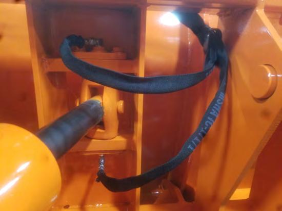
19 5.5: Grease all lines and ensure grease contacts pins. Figure 2-7: Hose 2-3 Clamping Figure 2-8:Hose 4-9 Clamping Figure 2-9:Hose Clamping Figure 2-10:Hose Clamping PLP_REMOTE_GREASE_ASY_EFF_ALL_ _01_010 Page 19 of 28

20 Figure 2-11:Hose Clamping PLP_REMOTE_GREASE_ASY_EFF_ALL_ _01_010 Page 20 of 28
21 CHAPTER 3: MAINTENANCE PLEASE READ ENTIRE BOOK BEFORE INSTALLATION, OPERATION, OR MAINTENANCE. PLP_REMOTE_GREASE_ASY_EFF_ALL_ _01_010 Page 21 of 28
22 In Season Maintenance Snow removal equipment must be cared for and maintained regularly. Daily or pre-route inspection and maintenance are necessary. Failure to do so may affect efficiency and safety. A visual inspection must be carried out after every 8 hours of operation. Look for damaged components, bends, cracked welds or hydraulic leaks. REPAIR IMMEDIATELY! Re-torque all bolts after the first 8 hours of use and to regularly check for loosened or missing fasteners. Replace any damaged or missing fasteners immediately. Because of the environment in which snow equipment is expected to operate, hydraulic lines, fasteners, wearable or replaceable items and warning decals may become damaged by snow, ice and road debris. These items must be inspected daily and replaced if necessary to avoid equipment damage or personal injury. Lubrication of moving parts is of the utmost importance. Exposure to snow, ice, salt and road debris will wash away lubrication quickly and it may be necessary to inspect and reapply lubrication more than once a day. PLP_REMOTE_GREASE_ASY_EFF_ALL_ _01_010 Page 22 of 28
23 End Of Season Maintenance GROUND ENGAGING COMPONENTS CUTTING EDGES & GUARDS: Replace any broken cutting edges, unevenly or excessively worn cutting edges, and broken or worn wear guards. RUNNING GEAR: Replace broken, worn, or missing running gear shoes, and any damaged adjuster leg components. Grease internal threads and sliding members (it s best to disassemble and grease directly; zerks aren t as effective at greasing these areas). HARDWARE: Replace missing or broken bolts. Proper torque is important! Use grade 8 plow bolts for steel cutting edges. HYDRAULICS HOSES: Plug or cap any QC fittings or any open hose ends. Inspect hoses for any leaks or potential leaks. Secure hoses with hose clamps. CYLINDERS: Check for leaks, and any chrome rod dents or scratches. Apply a light coat of oil or grease on exposed rod surfaces. FRAME AND MOLDBOARD JOINTS: Check pins, bushings, and pivot bolts for wear. Make sure all keepers are in place. Make sure shear bolts and pins are same as original equipment (usually grade 2). Some drivers don t like replacing shear pins and will install grade 8 replacements to avoid replacing during a storm. These items are designed to shear to protect driver and equipment. CHECK WELDMENTS FOR CRACKS. CABLE AND SHEAVES CABLE: Check cable thoroughly for fraying, kinks, and abnormal wear. Make sure cable is properly routed and seated in all sheaves. Verify that cable clamps have proper torque and are in correct orientation and spacing. Cable shall be checked prior to each use or after every 8 hours, whichever comes first. SHEAVES: Verify that sheave, bushings and retaining pins are in good condition and adequately greased. Make sure that sheaves, bushings and pins do not have any abnormal wear and rotate without restriction. REPLACE WORN OR BROKEN PARTS FOUND BY ABOVE INSPECTIONS PLP_REMOTE_GREASE_ASY_EFF_ALL_ _01_010 Page 23 of 28

24 MAINTENANCE MAINTENANCE Spreader 01/16 Maintenance Section Alamo Group Inc.
25 CHAPTER 4: WARRANTY & DEALER PROCEDURE PLEASE READ ENTIRE BOOK BEFORE INSTALLATION, OPERATION, OR MAINTENANCE. PLP_REMOTE_GREASE_ASY_EFF_ALL_ _01_010 Page 25 of 28
26 1.0 LIMITED WARRANTIES HENKE LIMITED WARRANTY 1.1 Henke warrants for one year from the purchase date to the original non-commercial, governmental, or municipal purchaser ( Purchaser ) and warrants for twelve months to the original commercial or industrial purchaser Parts manufactured by Henke are warranted to be free from defects in materials and/or workmanship for a period of 12 months from date of purchase when used under normal operating conditions, used in a proper application and have been provided any/all maintenance is performed as recommended Any parts or accessories not manufactured by Henke are warranted only to the extent that the manufacturer's warranty may be passed on to the purchaser and such parts and accessories are not subject to Henke's warranty or to any other warranty expressed or implied. 1.2 Manufacturer will repair or replace for the Purchaser any part or parts found, upon examination at one of its factories, to be defective under normal use and service due to defects in material or workmanship. 1.3 This limited warranty does not apply to any part of the goods which has been subjected to improper or abnormal use, negligence, alteration, modification, or accident, damaged due to lack of maintenance or use of wrong fuel, oil, or lubricants, or which has served its normal life. This warranty does not include normal wear items such as cutting edges, wear guards, scarifier teeth, etc. or improper installation. HMC warranty for any purchased components, such as hydraulic cylinders will be superseded by, and equal to the component manufacturer warranty. 1.4 Except as provided herein, no employee, agent, Dealer, or other person is authorized to give any warranties of any nature on behalf of Manufacturer. 2.0 REMEDIES AND PROCEDURES. 2.1 Warranty claims must be filled within 30 days of repair work during the one year warranty period and will be honored only if the completed warranty registration form has been returned. Henke reserves the right to require proof of purchase of original Henke replacement parts. If warranty is approved any allowed shipping expenses will be based on and will not exceed standard base shipping charges. 2.2 Purchaser claims must be made in writing to the Authorized Dealer ( Dealer ) from whom Purchaser purchased the goods or an approved Authorized Dealer ( Dealer ) within 30 days after Purchaser learns of the facts on which the claim is based. 2.3 Purchaser is responsible for returning the goods in question to the Dealer If after examining the goods and/or parts in question, Manufacturer finds them to be defective under normal use and service due to defects in material or workmanship, Manufacturer will: Repair or replace the defective goods or part(s) or Reimburse Purchaser for the cost of the part(s) and reasonable labor charges (as determined by Manufacturer) if Purchaser paid for the repair and/or replacement prior to the final determination of applicability of the warranty by Manufacturer The choice of remedy shall belong to Manufacturer. 2.4 Purchaser is responsible for any labor charges exceeding a reasonable amount as determined by Manufacturer and for returning the goods to the Dealer, whether or not the claim is approved. Purchaser is responsible for the transportation cost for the goods or part(s) from the Dealer to the designated factory. 3.0 LIMITATION OF LIABILITY. 3.1 MANUFACTURER DISCLAIMS ANY EXPRESS (EXCEPT AS SET FORTH HEREIN) AND IMPLIED WARRANTIES WITH RESPECT TO THE GOODS INCLUDING, BUT NOT LIMITED TO, MERCHANTABILITY AND FITNESS FOR A PARTICULAR PURPOSE. 3.2 MANUFACTURER MAKES NO WARRANTY AS TO THE DESIGN, CAPABILITY, CAPACITY, OR SUITABILITY FOR USE OF THE GOODS. 3.3 EXCEPT AS PROVIDED HEREIN, MANUFACTURER SHALL HAVE NO LIABILITY OR RESPONSIBILITY TO PURCHASER OR ANY OTHER PERSON OR ENTITY WITH RESPECT TO ANY LIABILITY, LOSS, OR DAMAGE CAUSED OR ALLEGED TO BE CAUSED DIRECTLY OR INDIRECTLY BY THE GOODS INCLUDING, BUT NOT LIMITED TO, ANY INDIRECT, SPECIAL, CONSEQUENTIAL, OR INCIDENTAL DAMAGES RESULTING FROM THE USE OR OPERATION OF THE GOODS OR ANY BREACH OF THIS WARRANTY. NOT WITHSTANDING THE ABOVE LIMITATIONS AND WARRANTIES, MANUFACTURER S LIABILITY HEREUNDER FOR DAMAGES INCURRED BY PURCHASER OR OTHERS SHALL NOT EXCEED THE PRICE OF THE GOODS. 3.4 NO ACTION ARISING OUT OF ANY CLAIMED BREACH OF THIS WARRANTY OR TRANSACTIONS UNDER THIS WARRANTY MAY BE BROUGHT MORE THAN TWO (2) YEARS AFTER THE CAUSE OF ACTION HAS OCCURRED. 4.0 MISCELLANEOUS. 4.1 Proper Venue for any lawsuits arising from or related to this limited warranty shall be only in Leavenworth County, Kansas. 4.2 Manufacturer may waive compliance with any of the terms of this limited warranty, but no waiver of any terms shall be deemed to be a waiver of any other term. 4.3 If any provision of this limited warranty shall violate any applicable law and is held to be unenforceable, then the invalidity of such provision shall not invalidate any other provisions herein. 4.4 Applicable law may provide rights and benefits to purchaser in addition to those provided herein.
27 5.0 KEEP FOR YOUR RECORDS: ATTENTION: Purchaser should fill in the blanks below for his reference when buying repair parts and/or for proper machine identification when applying for warranty. Henke Product Model: Date Purchased: READ YOUR OPERATOR'S MANUAL Serial Number: Dealer: HENKE MANUFACTURING An Alamo Group Company 3070 WILSON AVE. LEAVENWORTH, KS (888)
28 Dealer Warranty Procedure For units delivered within the past 12 months, report any warranty problems needing repair to our Product support department. Please have information ready regarding: 1. Henke unit model and serial number, 2. Model of equipment Henke unit is attached to (prime mover) 3. Description of the problem and any helpful information by the end user. (Photos are always helpful). Measurements or photos may be requested by Henke engineering for any issues regarding prime mover proximity and clearance, or any other unique considerations of fit and adaptability. These may be necessary for a proper repair recommendation and procedure. Henke will respond with a written labor hour allowance for Henke participation on a faxed claim form and will ship any required replacement parts. If necessary, a repair procedure will be included on the claim form. A parts invoice will be generated to confirm shipment of the replacement parts. If defective parts are needed for analysis, Henke will request their return. Any such returned items are to be labeled with the claim number and returned to: HENKE MANUFACTURING CORPORATION ATTN: Product Support 3070 WILSON AVE. LEAVENWORTH, KS RGA# The dealer should perform repairs as agreed on a dealer warranty repair order. Return the claim form with a copy of the dealer warranty repair order and service report. Credit as agreed will be issued to the dealer upon receipt of the dealer warranty repair order invoice (Pro-forma invoice), and upon receipt, inspection and warranty confirmation of the returned parts if any. Parts & Service Assistance Parts inquiries may be ed at any time to parts@henkemfg.com. s are encouraged, as this will direct your inquiry to the entire parts and service team, insuring the most prompt attention possible. All inquiries are processed in the order they are received. Parts and service assistance is also available, Monday through Friday, from 7:00 am to 4:30 pm, CST, call (913) x3, or Toll Free (888) x3. Our web site, is a quick source for parts pricing, and many common parts diagrams. Go to to submit a quick request ticket for parts. PLP_REMOTE_GREASE_ASY_EFF_ALL_ _01_010 Page 28 of 28
PART'S MANUAL. Rear Mounted Blade RHINO
 850 Revised 06-10 PART'S MANUAL Rear Mounted Blade Part No. 00787017P An Operator's Manual was shipped with the equipment in the Manual Canister. This Operator's Manual is an integral part of the safe
HENKE ALL-HYDRAULIC WING FOR JOHN DEERE GRADE PRO SERIES GRADERS
 HENKE ALL-HYDRAULIC WING FOR JOHN DEERE GRADE PRO SERIES GRADERS PARTS BOOK AND INSTALLATION MANUAL Serial Number: VERSION 2.4, DECEMBER 2016 HENKE MANUFACTURING CORPORATION MANUFACTURERS OF SNOW REMOVAL
DISC HARROW PART'S MANUAL DHP8/10/12. RHINO 1020 S. Sangamon Ave. Gibson City, IL
 DISC HARROW DHP8/10/12 Published 03/16 PART'S MANUAL P/N 00789085P An Operator's Manual was shipped with the equipment in the Manual Canister. This Operator's Manual is an integral part of the safe operation
Grizzly 52. Tree Cutter. OPERATOR S MANUAL with PARTS LISTING. ALAMO INDUSTRIAL 1502 E. Walnut Seguin, Texas
 Grizzly 52 Tree Cutter Published (06-05) Part No. 02975192 OPERATOR S MANUAL with PARTS LISTING ALAMO INDUSTRIAL 1502 E. Walnut Seguin, Texas 78155 830-379-1480 2005 Alamo Group Inc. An Alamo Group Company
BOX BLADES PART'S MANUAL SBX/MBX/RO. RHINO 1020 S. Sangamon Ave. Gibson City, IL
 Published 03/6 BOX BLADES PART'S MANUAL SBX/MBX/RO P/N 0078930P An Operator's Manual was shipped with the equipment in the Manual Canister. This Operator's Manual is an integral part of the safe operation
PART'S MANUAL 3-POINT POSTHOLE DIGGER 130P, 240P, 340P, & 440P
 3-POINT POSTHOLE DIGGER 130P, 240P, 340P, & 440P Rev 05-07 PART'S MANUAL Part No. 01430870P An Operator's Manual was shipped with the equipment in the Manual Canister. This Operator's Manual is an integral
RVT SERIES HEAVY DUTY TRIPPING SNOW PLOW
 RVT SERIES HEAVY DUTY TRIPPING SNOW PLOW Model: Serial Number: Rev. 10/13 Rylind Manufacturing, Inc. 2801 Youngfield St Suite 250 Golden, CO 80401 Main Offices: 303-979-3548 Manufacturing Plant: 970-522-2859
RPD SERIES HEAVY AND SEVERE DUTY SNOW PLOW
 RPD SERIES HEAVY AND SEVERE DUTY SNOW PLOW Model: Serial Number: Rev. 01/14 Rylind Manufacturing, Inc. 2801 Youngfield St Suite 250 Golden, CO 80401 Main Offices: 303-979-3548 Manufacturing Plant: 970-522-2859
MDP Multi-Directional Folding-V Snow Plow
 MDP Multi-Directional Folding-V Snow Plow Model Number: Serial Number: Rev. 10/13 Rylind Manufacturing, Inc. 2801 Youngfield St Suite 250 Golden, CO 80401-2263 Business/Sales Offices: 303-979-3548 Manufacturing
Deere G & GP Series Snow Wing Installation
 Deere G & GP Series Snow Wing Installation Model: Serial Number: Rev. 10/13 Rylind Manufacturing, Inc. 2801 Youngfield St Suite 250 Golden, CO 80401 Offices: 303-979-3548 Fax: 303-979-4730 www.rylind.com
Snow Blower Published P/N 5048P PART'S MANUAL
 Snow Blower Published 08-05 P/N 5048P PART'S MANUAL An Operator's Manual was shipped with the equipment in the Manual Canister. This Operator's Manual is an integral part of the safe operation of this
Snow Blower Published P/N 5042P PART'S MANUAL
 Snow Blower Published 08-05 P/N 5042P PART'S MANUAL An Operator's Manual was shipped with the equipment in the Manual Canister. This Operator's Manual is an integral part of the safe operation of this
Snow Blower Published P/N 5041P PART'S MANUAL
 Snow Blower Published 08-05 P/N 5041P PART'S MANUAL An Operator's Manual was shipped with the equipment in the Manual Canister. This Operator's Manual is an integral part of the safe operation of this
Snow Blower Published P/N 5044P PART'S MANUAL
 Snow Blower Published 08-05 P/N 5044P PART'S MANUAL An Operator's Manual was shipped with the equipment in the Manual Canister. This Operator's Manual is an integral part of the safe operation of this
Snow Blower Published P/N 5043P PART'S MANUAL
 Snow Blower Published 08-05 P/N 5043P PART'S MANUAL An Operator's Manual was shipped with the equipment in the Manual Canister. This Operator's Manual is an integral part of the safe operation of this
8600-AR. Snow Blower Part No.5037P. RHINO 1020 S. Sangamon Ave. Gibson City, IL
 8600-AR Rev 07-05 PART'S MANUAL Snow Blower Part No.5037P An Operator's Manual was shipped with the equipment in the Manual Canister. This Operator's Manual is an integral part of the safe operation of
Revised Part No. 4928WP PART'S MANUAL
 DYNA-MASTER Revised 09-14-01 Part No. 4928WP PART'S MANUAL An Operator's Manual was shipped with the equipment in the Manual Canister. This Operator's Manual is an integral part of the safe operation of
TW14 PART'S MANUAL RHINO ROTARY MOWER
 Rev 11 PART'S MANUAL ROTARY MOWER Part No. 00792245P An Operator's Manual was shipped with the equipment in the Manual Canister. This Operator's Manual is an integral part of the safe operation of this
PART'S MANUAL. Rear Mounted Blade. RHINO 1020 S. Sangamon Ave. Gibson City, IL
 2500 PART'S MANUAL Rear Mounted Blade Rev 02-16 Part No. 00767428P An Operator's Manual was shipped with the equipment in the Manual Canister. This Operator's Manual is an integral part of the safe operation
8650-AR. Snow Blower Part No.5039P. RHINO 1020 S. Sangamon Ave. Gibson City, IL
 8650-AR Pub 02-05 PART'S MANUAL Snow Blower Part No.5039P An Operator's Manual was shipped with the equipment in the Manual Canister. This Operator's Manual is an integral part of the safe operation of
Published Part No P PARTS MANUAL
 A60/A72/A72SD Rotary Mower Published 03-04 Part No. 00757274P PARTS MANUAL An Operator's Manual was shipped with the equipment in the Manual Canister. This Operator's Manual is an integral part of the
Published Effective Serial No through Current Part No P PARTS MANUAL
 TREE CUTTER Published 07-05 Effective Serial No. 10240 through Current Part No. 00772057P PARTS MANUAL An Operator's Manual was shipped with the equipment in the Manual Canister. This Operator's Manual
UNDERBODY SCRAPER, FIXED ANGLE
 UNDERBODY SCRAPER, FIXED ANGLE HENKE MODEL: UBS FA,17 FOR: Medium to Heavy Duty Trucks PARTS AND INSTALLATION MANUAL: # 8430302-01 VERSION 010, JUNE 2017 MY SERIAL NUMBER: HENKE MANUFACTURING CORPORATION
PPM EO-100 TM. Operation Manual
 PPM EO-100 TM Open Loop Electric Prewet Power Module Operation Manual Rev A Page 1 2/23/2010 Copyright 2008 by Cirus Controls, LLC. All Rights Reserved. No part of this material may be reproduced in any
PARTS MANUAL AG60B & AG72B. Rotary Mower. ALAMO INDUSTRIAL 1502 E. Walnut Seguin, Texas Alamo Group Inc.
 AG60B & AG72B Rotary Mower Published 03/04 Effective Serial No. A60B-01820 To Current Part No.00759354P Effective Serial No. A72B-02600 To Current PARTS MANUAL An Operator's Manual was shipped with the
Heavy Duty Four Wheeled Walker
 Heavy Duty Four Wheeled Walker Weight Capacity: 500 lbs. ITEM # W1802 Made in China 2011 ESSENTIAL MEDICAL SUPPLY, INC. Manufactured for Orlando, FL 32822 -- SAVE THESE INSTRUCTIONS -- Do not attempt to
INSTALLATION INSTRUCTIONS
 REV 3 05/13/2016 INSTALLATION INSTRUCTIONS PART NO. 960001T 960003T PRODUCT DESCRIPTION: Full size Powered Light Bar Mid size Powered Light Bar Sport Bar and lights sold separately shown for reference
UNDERBODY SCRAPER, REVERSIBLE, EXTRA HEAVY
 UNDERBODY SCRAPER, REVERSIBLE, EXTRA HEAVY HENKE MODEL: UBS XH FOR: Medium to Heavy Duty Trucks PARTS AND INSTALLATION MANUAL: # 8430102-01 VERSION 016, AUGUST 2018 MY SERIAL NUMBER: HENKE MANUFACTURING
Fifth Wheel Power Hitch Operations Manual
 Fifth Wheel Power Hitch Operations Manual ITD1253 Fifth Wheel Power Hitch 208 587 7960 www.intheditch.com This page is intentionally left blank. Operations Manual 1 TABLE OF CONTENTS TABLE OF CONTENTS...
INSTALLATION INSTRUCTIONS
 REV 3 05/13/2016 PART NO. RB610T RB620T PRODUCT DESCRIPTION: RB10 Hitch Step RB20 Hitch Step PRODUCT SAFETY & LEGAL DISCLAIMER IMPORTANT READ ALL INSTRUCTIONS CAREFULLY BEFORE INSTALLING, FAILURE TO DO
INSTALLATION INSTRUCTIONS
 REV 3 05/13/2016 INSTALLATION INSTRUCTIONS PART NO. 55311T / 55316T / 55321T 55326T / 55341T / 55346T PRODUCT DESCRIPTION: RC2 LR CENTRAL MOUNT RC2 LR BOTTOM MOUNT PRODUCT SAFETY & LEGAL DISCLAIMER IMPORTANT
THIS MANUAL INCLUDES. Balderson Style Lift Head With Manual Locking Pins Balderson Style Lift Head With Hydraulic Locking Pins
 PARALLEL LIFT GROUP HENKE MODEL: PLG11, STD and HLP For: John Deere C, D, G, or GP Series Motor Graders THIS MANUAL INCLUDES Balderson Style Lift Head With Manual Locking Pins Balderson Style Lift Head
INSTALLATION INSTRUCTIONS
 REV 3 05/13/2016 INSTALLATION INSTRUCTIONS PART NO. 530000T 530003 PRODUCT DESCRIPTION: LIGHTNING SERIES SPORT BAR APPLICATION: FORD SUPER DUTY 6.5 & 8 STYLESIDE PICKUP BOX PRODUCT SAFETY & LEGAL DISCLAIMER
INSTALLATION INSTRUCTIONS
 REV 3 05/13/2016 INSTALLATION INSTRUCTIONS PART NO. 702001T PRODUCT DESCRIPTION: FRONT INNER FENDER LINER APPLICATION: JEEP WRANGLER / WRANGLER UNLIMITED PRODUCT SAFETY & LEGAL DISCLAIMER IMPORTANT READ
Grapple Kit Install & Grapple Bucket Manual
 Grapple Kit Install & Grapple Bucket Manual Model # Serial # Rev. 10/13 Rylind Manufacturing, Inc. 2801 Youngfield St Suite 250 Golden, CO 80401 Business/Sales Offices: 303-979-3548 Manufacturing Plant:
PART'S MANUAL. Rear Mounted Blade. RHINO 1020 S. Sangamon Ave. Gibson City, IL
 1540 PART'S MANUAL Rear Mounted Blade Rev 03-16 Part No. 697PB An Operator's Manual was shipped with the equipment in the Manual Canister. This Operator's Manual is an integral part of the safe operation
JOHN DEERE 9970 COTTON PICKERS
 PARTS CATALOG FOR Mud Hog System II Rear Wheel Drive FOR JOHN DEERE 9970 COTTON PICKERS Mud Hog Model Numbers Tread Center OEM Aftermarket JD40005 JD47655 82, 90, 94, 106 TUTHILL Drive Systems 9098 West
INSTALLATION INSTRUCTIONS
 REV 2 12/7/2016 INSTALLATION INSTRUCTIONS PART NO. 6841555 PRODUCT DESCRIPTION: OE XTREME BRACKETS PRODUCT SAFETY & LEGAL DISCLAIMER APPLICATION: FORD F-150, F-250, F-350 REGULAR CAB FORD F-250, F-350
Extreme Duty Grapple (Rock, Skeleton, Scrap & Tine) Operation and Maintenance Manual
 Operation and Maintenance Manual") Extreme Duty Grapple (Rock, Skeleton, Scrap & Tine) Operation and Maintenance Manual Revision Date: July 2017 Skid Pro PO Box 982 Alexandria, MN 56308 Toll Free: 877-378-4642 www.skidpro.com TABLE OF CONTENTS
Extreme Duty Grapple (Rock, Skeleton, Scrap & Tine) Operation and Maintenance Manual Revision Date: July 2017 Skid Pro PO Box 982 Alexandria, MN 56308 Toll Free: 877-378-4642 www.skidpro.com TABLE OF CONTENTS
INSTALLATION INSTRUCTIONS
 REV 3 05/13/2016 PART NO. 24373T PRODUCT DESCRIPTION: BR10 BUMPER REPLACEMENT APPLICATION: FORD F-250 & F-350 SUPER DUTY EXCLUDES MODELS WITH ADAPTIVE CRUIS CONTROL PRODUCT SAFETY & LEGAL DISCLAIMER IMPORTANT
INSTALLATION INSTRUCTIONS
 REV 3 05/13/2016 INSTALLATION INSTRUCTIONS PART NO. 69450673T & 69450673PC PRODUCT DESCRIPTION: RB20 RUNNING BOARDS APPLICATION: JEEP WRANGLER JL UNLIMITED PRODUCT SAFETY & LEGAL DISCLAIMER IMPORTANT READ
7.3L POWERSTROKE BANJO BOLT KIT Fits L Powerstroke Diesel. Installation Guide
 7.3L POWERSTROKE BANJO BOLT KIT Fits 94-03 7.3L Powerstroke Diesel Installation Guide INSPECT CONTENTS OF THIS KIT THOROUGHLY BEFORE STARTING THE INSTALLATION PROCESS! IF YOU FIND A PROBLEM WITH YOUR PACKAGE:
DYNA-DRIVE. M&W 1020 South Sangamon Ave. Gibson City, Illinois GROUND-DRIVEN CULTIVATOR
 DYNA-DRIVE GROUND-DRIVEN CULTIVATOR Rev 02-07 DD 60 S/N 10095 -CURRENT Part No. 00771093P PART'S MANUAL An Operator's Manual was shipped with the equipment in the Manual Canister. This Operator's Manual
DeZURIK 2 20" BOS BUTTERFLY VALVES
 2 20" BOS BUTTERFLY VALVES Instruction D10459 October 2013 2-20 BOS Butterfly Valves Instructions These instructions provide information about BOS Butterfly Valves. They are for use by personnel who are
HYDRO 88 & 96 PARTS MANUAL. Flail Cutter. ALAMO INDUSTRIAL 1502 E. Walnut Seguin, Texas
 HYDRO 88 & 96 PARTS MANUAL Flail Cutter Rev 03-3 P/N 8033 An Operator's Manual was shipped with the equipment in the Manual Canister. This Operator's Manual is an integral part of the safe operation of
INSTALLATION INSTRUCTIONS
 REV 3 05/13/2016 PART NO. 911000T 911000PS 915000T 915000PS PRODUCT DESCRIPTION: Sport Bar 2.0, Full size Textured Black Sport Bar 2.0, Full size Polished Stainless Steel Tubes Sport Bar 2.0, Mid size
INSTALLATION INSTRUCTIONS
 REV 3 05/13/2016 INSTALLATION INSTRUCTIONS PART NO. 702002T PRODUCT DESCRIPTION: REAR INNER FENDER LINER APPLICATION: JEEP WRANGLER / WRANGLER UNLIMITED PRODUCT SAFETY & LEGAL DISCLAIMER IMPORTANT READ
VAN STORAGE SOLUTIONS FOR THE WAY YOU WORK
 WWW.WEATHERGUARD.COM VAN STORAGE SOLUTIONS FOR THE WAY YOU WORK Weather Guard / KNAACK 420 E. Terra Cotta Ave. Crystal Lake, IL 60014 USA 800-456-7865 (Toll Free) 800-334-2981 (Fax) Knaack.OrderEntry@wernerco,.com
TITAN 13 x 2½ BRAKES DUO-SERVO AND FREE BACKING
 INSTALLATION INSTRUCTION AND SERVICE MANUAL Actuator/Trailer Dealer - Please provide these instructions to the consumer. Consumer - Read and follow these instructions. Keep them with the trailer for future
20250 Module Installation Guide
 20250 Module Installation Guide 2013.5-2017 RAM 6.7L Cummins Up to 90HP Gain 1-3 MPG Fuel Savings AgDieselSolutions.com Adjustable switch connector Power +12 volts (Red wire) & Ground (Black wire) Injector
APCO CRF-100A RUBBER FLAPPER SWING CHECK VALVES
 APCO CRF-100A RUBBER FLAPPER SWING CHECK VALVES Instruction D12043 June 2016 DeZURIK Instructions These instructions provide installation, operation and maintenance information for APCO CRF-100A Rubber
Extreme Duty Grapple (Rock, Skeleton, Scrap & Tine) Operation and Maintenance Manual
 Operation and Maintenance Manual") Extreme Duty Grapple (Rock, Skeleton, Scrap & Tine) Operation and Maintenance Manual Revision Date: May 12, 2017 Skid Pro PO Box 982 Alexandria, MN 56308 Toll Free: 877-378-4642 www.skidpro.com TABLE OF
Extreme Duty Grapple (Rock, Skeleton, Scrap & Tine) Operation and Maintenance Manual Revision Date: May 12, 2017 Skid Pro PO Box 982 Alexandria, MN 56308 Toll Free: 877-378-4642 www.skidpro.com TABLE OF
Installation Instructions
 85-4341 rev. 04 10-15 Installation Instructions Thank you for purchasing this antisway bar kit. Please read through these instructions before installation. Rear Anti-Sway Bar Kit for Chevy 2500/3500/4500
Operating Instructions and Parts Manual AHR-50 Auto Rewind Hose Reel
 Operating Instructions and Parts Manual AHR-50 Auto Rewind Hose Reel JET 427 New Sanford Road LaVergne, Tennessee 37086 Part No. M-426238 Ph.: 800-274-6848 Revision C 04/2017 www.jettools.com Copyright
Female Plug. connecting to Fuel Quantity
 **Ag Diesel Solutions recommends replacing the Transorb/Suppressor Diode before the installation of this module*** Red wire = 12V Constant power. Male Plug connecting to Fuel Quantity Valve Black wire
ActuLink ABS Module - ABS-MOD-400
 Installation Instructions ActuLink ABS Module - ABS-MOD-400 For more information on the installation and operation of Tuson s towable ABS system, consult the installation and operations manuals for the
GM 6.6L Duramax. Up to 90HP Gain. AgDieselSolutions.com
 21700 Module Installation Guide 2017 GM 6.6L Duramax *L5P* Up to 90HP Gain 1-3 MPG Fuel Savings AgDieselSolutions.com Adjustable Switch Female Fuel Pressure Sensor Connector Male Fuel Pressure Sensor Connector
Hydro 88 & 96 PARTS MANUAL. ALAMO INDUSTRIAL 1502 E. Walnut Seguin, Texas Flail
 Hydro 88 & 96 Flail Rev 0- PARTS MANUAL Part No.8033 ALAMO INDUSTRIAL 50 E. Walnut Seguin, Texas 7855 830-37-9595 An Operator's Manual was shipped with the equipment in the Manual Canister. This Operator's
RED23305 Owner s Manual
 RED23305 Owner s Manual 5 foot, 3-Point Mounted Snow Blower 270 West Park Avenue Huron, SD 57350 866-526-5682 Serial Number: Date of Purchase: Red Devil Snow Blower See Figure 1. 1. The Red Devil Snow
OWNER S GUIDE 8A DURALIFT II 13,200 LB. CAPACITY. Link Mfg. Ltd th St. N.E. Sioux Center, IA USA
 OWNER S GUIDE 8A000715 DURALIFT II 13,200 LB. CAPACITY Link Mfg. Ltd. 223 15th St. N.E. Sioux Center, IA USA 51250-2120 www.linkmfg.com QUESTIONS? CALL CUSTOMER SERVICE 1-800-222-6283 DEALER / INSTALLER:
Mercedes MBE 906/ L & 7.2L Engine Module. Part # Installation Instructions
 1999-2006 Mercedes MBE 906/926 6.4L & 7.2L Engine Module Part # 15000 Installation Instructions 15000_revC 1999-2006 Mercedes 6.4L & 7.2L Engine Module +12 volts red wire. Ground black wire Injector Terminals
Pub 11/ S/N CURRENT 1465 S/N CURRENT
 EARTHMASTER Pub 11/05 1165 S/N 2300 -CURRENT Part No. 4353P 1465 S/N 1239 -CURRENT PART'S MANUAL An Operator's Manual was shipped with the equipment in the Manual Canister. This Operator's Manual is an
HSIV PLOW OPERATOR S MANUAL
 PLOW RWF INDUSTRIES 873 Devonshire Ave., Woodstock, Ontario N4S 8Z4 Tel: (519) 421-0036 Toll Free: 1-800-263-1060 Fax: (519) 421-0028 Email: parts@rwfbron.com JANUARY 2015 THE INFORMATION CONTAINED IN
4200 & 6200 Owner s Manual & Parts Book
 00 & 00 Owner s Manual & Parts Book Purchase Date Serial Number Model Number Tractor Model PN: - Dealer Date --0 Description Page To The Owner & Maintenance Safety Precautions & Torque Specifications Skid
Installation Instructions
 Nov 25, 2013 Custom Bent Brake Line Kit '67-'69 Camaro and '68-'74 Nova Installation Instructions The following instructions are intended for professional installers and are guidelines only. Speedtech
END USER TERMS OF USE
 END USER TERMS OF USE The following is the End Users Terms of Use as it currently appears in the Mobileye User Manual and Warranty information. This is here for your review and information; it is subject
GERINGHOFF. Corn Header Manual f HEADSIGHT.COM
 GERINGHOFF Corn Header Manual 09020701f HEADSIGHT.COM 574.546.5022 About Headsight Headsight Contact Info Headsight, Inc. 4845 3B Road Bremen, IN 46506 Phone: 574-546-5022 Fax: 574-546-5760 Email: info@headsight.com
HIGH DUMP ROLL-OUT BUCKET
 HIGH DUMP ROLL-OUT BUCKET Model # Serial # Rev. 01/14 Rylind Manufacturing, Inc. 2801 Youngfield St Suite 250 Golden, CO 80401 Business/Sales Offices: 303-979-3548 Manufacturing Plant: 970-522-2859 www.rylind.com
Installation Instructions
 85-3511 rev. 04 11-15 Installation Instructions Polyurethane Bushing Kit for Ford F-53 (Front) (replaces OE bushings and brackets) part #4139-127 1-5/8 diameter INTRODUCTION Thank you for purchasing this
PVI 60KW, PVI 82KW, PVI 95KW
 PVI 60KW PVI 82KW PVI 95KW WARRANTY MANUAL Commercial, Grid-Tied Photovoltaic Inverters 2008, Solectria Renewables LLC Subject to Change DOC-020099 rev 024 1 1 Product Warranty & RMA Policy Warranty Policy
DODGE CUMMINS Arctic-Heat Grid Relocation Kit
 Installation Manual P/N 07509-350-GRK 2007.5-09 DODGE CUMMINS Arctic-Heat Grid Relocation Kit Installation Instructions P/N 07509-350-GRK GDP Arctic-Heat Grid Heater Installation PLEASE READ ALL INSTRUCTIONS
JD2800 Module Installation Guide
 Up to 30% More Horsepower 10-20% Fuel Savings John Deere 9.0L Tier III Denso Common Rail Engines JD2800 Module Installation Guide AgDieselSolutions.com Ground Terminal Power (+12V constant) Terminal Injector
Quadratec Dual Steering Stabilizer Kit
 Quadratec Dual Steering Stabilizer Kit Installation Manual: for 97-06 (TJ) Wrangler # 16116.0202 PARTS LIST: Steering Damper - Qty 2 Black Boot & Boot Tie - Qty 2 (each) Decal - Qty 2 Hourglass Bushing
Installation Instructions
 85-4209 rev. 05 11-18 Installation Instructions Thank you for purchasing this anti-sway bar kit. Please read through these instructions before installation. Factory Replacement Anti-Sway Bar Kit part #1129-135
INSTALLATION INSTRUCTIONS SINGLE HORIZONTAL ACCESS DOOR PANTRY INSERT MANUAL
 INSTALLATION INSTRUCTIONS MODEL #88972 SINGLE HORIZONTAL ACCESS DOOR PANTRY INSERT MANUAL TABLE OF CONTENTS PAGE # INSTALLATION INSTRUCTIONS...................2 CABINET LOCATION GUIDELINES...2 REGULAR
AIR CONTROL ACCESSORY KIT
 RAPID RESPONSE SYSTEM 2283 AIR CONTROL ACCESSORY KIT INSTALLATION INSTRUCTIONS Congratulations on your purchase of a new Air Control Accessory Kit. This kit was designed to provide inflation control of
30100 Module Installation Guide L
 30100 Module Installation Guide 1997-2006 12.0L Mack Engines Up to 30% HP Gain 10-20% Fuel Savings AgDieselSolutions.com 1997-2006 Mack 12.0L Engine Module +12 volts red wire. Ground black wire Injector
Model 35 PARTS MANUAL
 Model 35 PARTS MANUAL Version 3-2007 Ashland Industries Inc. 1115 Rail Drive P.O. Box 717 Ashland, WI. 54806 Ph: 877-634-4622 Toll Free Ph: 715-682-4622 Fx: 715-682-9717 www.ashlandind.com Model 35 Scraper
Dec 1, 2017 ATS AFX Spindle Installation Instructions
 Dec 1, 2017 ATS AFX Spindle Installation Instructions 1 P a g e The following instructions are intended for professional installers and are guidelines only. Speedtech Performance assumes NO responsibility
BX7322 Adventurer Tow Bar Operator Manual & Installation Instructions
 Please visit www.blueox.com for the latest version of these installation instructions. BX7322 Operator Manual & Installation Instructions Serial Number (5,000 lb) 2 Inch Coupler 292-1263 Rev J Page 1 of
ATV TRACK KIT. Operator s Manual Installation Instructions Service Instructions Replacement Parts List. Effective Date: October, 2012
 p/n 2258-642 ATV TRACK KIT Operator s Manual Installation Instructions Service Instructions Replacement Parts List Track Assembly Kits (p/n 1436-204) Mounting Assembly Kits (p/n 1436-205) 1436-815) Effective
INSTALLATION MANUAL #29 FOR CHEVY DIESEL PICKUP TRUCKS. MODEL RP-100 & RP-150 With New Quick Connect Components
 INSTALLATION MANUAL #29 FOR Fuel Inlet ON Left Side 1992-2000 CHEVY DIESEL PICKUP TRUCKS Fuel Inlet ON Left Side MODEL RP-100 & RP-150 With New Quick Connect Components READ THESE INSTRUCTIONS THOROUGHLY
Installation Instructions
 Nov 3, 2017 G-Body Rear Coilover Conversion Kit 1 P a g e Installation Instructions The following instructions are intended for professional installers and are guidelines only. Speedtech Performance assumes
TABLE OF CONTENTS. Warranty Disclaimers Delivery Checklist After Sale Checklist Safety Set Up... 8
 TABLE OF CONTENTS Pickett Equipment Warranty... 2 Warranty Disclaimers... 3 Delivery Checklist... 4 After Sale Checklist... 4 Safety... 5-7 Set Up... 8 Machine Adjustments and Operation... 9 Maintenance
Replacement Steering Stabilizer Kit
 Replacement Steering Stabilizer Kit Installation Manual: for 87-95 (YJ) and 97-06 (TJ) Wrangler # 16116.0200 PARTS LIST: Steering Damper Black Boot & Boot Tie Decal Hourglass Bushing - Qty 2 Sleeve - Qty
APCO ASR-400/450 SEWAGE AIR RELEASE VALVES
 APCO ASR-400/450 SEWAGE AIR RELEASE VALVES Instruction D12005 December 2012 Instructions These instructions provide installation, operation and maintenance information for the APCO ASR- 400/450 Sewage
MANUAL NO CREATED: 08/08/2012 MMH REV A STEEL COMPANY R 65 BUSHEL MINI-BIN PARTS AND ASSEMBLY MANUAL
 MANUAL NO. 195988 CREATED: 08/08/2012 MMH REV A STEEL COMPANY R 65 BUSHEL MINI-BIN PARTS AND ASSEMBLY MANUAL TABLE OF CONTENTS SAFETY AND STATEMENTS OF IMPORTANCE... 2 GENERAL INFORMATION... 3 ASSEMBLY
QUADBOSS UTV STRAIGHT PUSH TUBE OWNER S MANUAL
 PAGE of 6 PART #938 QUADBOSS UTV STRAIGHT PUSH TUBE OWNER S MANUAL This owner s manual covers all aspects of your new push tube including assembly, replacement parts, installation, warranty, and troubleshooting.
DRAGO. Corn Header Manual f HEADSIGHT.COM
 DRAGO Corn Header Manual 09020801f HEADSIGHT.COM 574.546.5022 About Headsight Headsight Contact Info Headsight, Inc. 4845 3B Road Bremen, IN 46506 Phone: 574-546-5022 Fax: 574-546-5760 Email: info@headsight.com
AG PRO SS Owner s Manual & Parts Book
 AG PRO SS Owner s Manual & Parts Book Purchase Date Serial Number Model Number Tractor Model Dealer PN: 63-19460 SN: 10204276-... Date 1-10-2017 Description Contents Page To The Owner, Maintenance, Safety
INVERTER HARNESS INSTALLATION FOR FREIGHTLINER CASCADIA
 FOR FREIGHTLINER CASCADIA Part #: P808 1004FC 08/05/2014 Doc 1.04 INST065 Page 1 Step 1: Unpack the plate assembly and both positive and negative cables. INSTALLATION INSTRUCTIONS Step 2: Insert the negative
TONS. Before each shift: Before operating: Before initial operation of hoist:
 LEVER HOIST 0.25 9 TONS Manual Notice It is the responsibility of the owner/user to install, inspect, test, maintain, and operate these lever hoists in accordance with ASME B30.21, Safety Standard for
Installation Instructions
 85-3909 rev. 01 09-09 Installation Instructions Thank you for purchasing this anti-sway bar kit. Please read through these instructions before installation. Rear Anti-Sway Bar Kit for Chevrolet G30 part
Granatelli Front & Rear Sway Bars FOR MUSTANG GT and V6 Part # GM-SB0507 INSTALLATION INSTRUCTIONS
 Granatelli Motor Sports, Inc. 1000 Yarnell Place Oxnard, CA 93033-2454 805-486-6644 (Phone) 805-486-6684 (Fax) Hours: M-F 8AM-5PM (PST) www.granatellimotorsports.com/ TechSupport@GranatelliMotorSports.com
Model AS-RC3260 TV Cart. Rolling Cart for Audio Mount System & Flat Panel TVs
 Model AS-RC3260 TV Cart Rolling Cart for Audio Mount System & Flat Panel TVs GETTING STARTED Introduction Congratulations on the purchase of your new Helios AS-RC3260 Rolling Cart. For maximum benefit,
Rig Master Power by Mobile Thermo Systems Inc.
 RigMaster Power Dealer Warranty Policy The Limited Warranty This limited warranty applies to the RigMaster Auxiliary Power Unit (RigMaster APU) which consists of the following components: 1. The generator
Exten-A-Kut II PARTS MANUAL. ALAMO INDUSTRIAL 1502 E. Walnut Seguin, Texas Rotary Ditch and Bank Mower
 Exten-A-Kut II Rotary Ditch and Bank Mower Rev 0- PARTS MANUAL Part No. 099P ALAMO INDUSTRIAL 0 E. Walnut Seguin, Texas 78 80-7-99 An Operator's Manual was shipped with the equipment in the Manual Canister.
Sidewalk-Pro SP-50 Sidewalk-Pro SP-65
 O M D Sidewalk-Pro SP-50 Sidewalk-Pro SP-65 Trynex International 200 (REV 000) Table of Contents INTRODUCTION..............................................................................................
Installation Instructions
 Nov 25, 2013 Upper Control Arms Installation Instructions The following instructions are intended for professional installers and are guidelines only. Speedtech Performance assumes NO responsibility for
3-Pt. Quick Hitch. Owner s Manual
 3-Pt. Quick Hitch Owner s Manual WARNING: Read carefully and understand all ASSEMBLY AND OPERATION INSTRUCTIONS before operating. Failure to follow the safety rules and other basic safety precautions may