Design Engineering Manufacturing Conveying Knowledge, Workmanship, Solutions COMPONENT GUIDE ISO 9001 Certified
|
|
|
- Charity Hunter
- 6 years ago
- Views:
Transcription


1 OMPONNT UI esign ngineering Manufacturing Screw onveyors onveying Knowledge, Workmanship, Solutions Release ate ISO 9001 ertified


2 KWS profile ounded in 1972, KWS Manufacturing ompany, Ltd, is the leader in the design and manufacture of conveying equipment for the bulk material handling industry. Our primary ustomers are power transmission distributors, end users, engineering firms, system suppliers and original equipment manufacturers (OMs). s an ISO 9001 certified manufacturer, KWS provides the highest quality equipment and service to our ustomers. The KWS name stands for Knowledge, Workmanship and Solutions. Our large number of repeat ustomers shows our commitment to ustomer satisfaction. Our quality system ensures that your equipment is designed and manufactured to rigid specifications and validated by exceeding performance expectations. We also offer complete system design and engineered solutions for our ustomers. KWS is one of the largest conveyor manufacturers in North merica and continues to grow every year. KWS SRW ONVYOR OMPONNT UI Screw conveyors are a cost effective and reliable method of conveying bulk materials. Thousands of bulk materials are conveyed and processed daily utilizing screw conveyors. The KWS Screw onveyor omponent uide is an excellent resource for understanding and selecting the proper components for screw conveyors. The component guide is easy to use, with descriptions of every screw conveyor component and their proper use. Recommendations are provided to assist the screw conveyor designer on how to properly select components for a specific application.
3 Screw onveyor omponent uide Table Of ontents Using the KWS Screw onveyor uide... 1 Screws asic onveyor light and Pitch Types... 4 onveyor Screws: Helicoid Versus Sectional Helicoid Screw and lighting Sectional Screw and lighting Ribbon Screw ut Screw / ut and olded Screw Paddle Screw onveyors Screw onveyor inishes Kws Hardsurfacing for brasive pplications Internal ollars nd Lugs oupling olts Hangers U-Trough Hangers lared Trough Hangers Hanger earings Style 216 Hanger earing Style 226 Hanger earing Style Hanger earings Trough nds Trough nds without eet Trough nds with eet Pedestal Trough nds lush nd ischarge Trough nds ulkhead Trough nds Torque rm Trough nds Seals Plate and Waste Pack Seal Split land and langed land Seal nd earings Roller earing lange Unit all earing lange Unit Roller earing Pillow lock all earing Pillow lock Shafts oupling Shaft lose oupling Shaft nd Shaft Hanger nd Shaft Roller Thrust earing Shaft ulkhead Shaft Torque rm Shaft Troughs U-Troughs lared Troughs Tubular Troughs Rectangular Troughs Plate nd langes U Trough Plate nd langes lared Trough Plate nd langes Tubular Trough Plate nd langes Rectangular Plate nd langes U Trough and Rectangular lush nd Plate nd lange.. 70 ischarge Spouts Inlet Spouts overs uttstraps and atten ars Hanger Pocket Saddles eet olt Requirements rive rrangements i
4 Screw onveyor omponent uide ii
5 Screw onveyor omponent uide RON STL STOK omponents Using the KWS Screw onveyor uide ach component specified in the KWS Screw onveyor omponent uide can be used in the design and manufacture of screw conveyors and screw feeders. very wide selection of components is provided so the engineer or designer can customize each screw conveyor or screw feeder for a specific application or need. Screw conveyors and screw feeders are used throughout the world for conveying and metering thousands of bulk materials and are the most versatile of all mechanical conveying devices. The KWS Screw onveyor omponent uide provides a description of each component along with dimensional information, weight and stock availability. KWS also offers the KWS Screw onveyor ngineering uide to better understand the design of screw conveyors and screw feeders. n example of KWS part number nomenclature is shown below. Please note that dimensions and weights of some standard components could change as design improvements are made, so please contact KWS ngineering or your KWS salesperson before finalizing your design. Nomenclature T = Trough nd Special eatures W = Without oot = lush nd = With oot H = ulkhead P = Pedestal T = Torque rm T O 9 2 U = rilled for all earing R = rilled for Roller earing R = Slotted for all and Roller earing U = U-Trough O = Outside Pattern Screw iameter 4 = 4 14 = = 24 6 = 6 16 = = 30 9 = 9 18 = = = = 20 Shaft iameter 1 = 1 3 = 112 = 1-1/ = 3-7/16 2 = = 3-15/ = 2-7/ = 4-7/16 ach component will contain either a onveyor iameter (onv. ia.) or Shaft ia., or both in order to help identify the size of the component Special eatures omponent amily Name 1
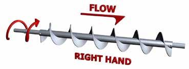
6 Screw onveyor omponent uide screws Screws can be configured for every application. The asic onveyor light and Pitch Type Section provides descriptions of various types of screws that can be used in a multitude of bulk material conveying and processing applications. The use of helicoid or sectional screws is dependent upon the requirements of the application and the needs of the end user. In general, helicoid screws are used in light to medium duty applications, and are more cost effective when compared to sectional screws. Sectional screws can be configured for almost every type of application with special features such as ribbon or cut-and-folded flighting. Sectional screws can also be manufactured from special materials such as R-235 or 316 stainless steel. Screw section length is also dependent upon the requirements of the application and the needs of the end user. Standard screw lengths and hanger bearings can be used where the bulk material is non-abrasive and free-flowing. Single length screws are recommended for abrasive, heavy industrial applications. Screws are available in right and left hand construction. Right hand screws are much more common and are recommended for almost every application. Spare parts are more readily available for right hand screws. The hand of a screw along with the direction of rotation of the screw determine the direction of bulk material flow. The diagrams below illustrate the direction of bulk material flow for both right hand and left hand screws when rotated clockwise or counter clockwise. The rotation arrows indicate the location of the motor and gear reducer. The direction of bulk material flow is reversed when the direction of rotation is reversed. right hand screw with the motor and gear reducer located on the discharge end pulls the bulk material toward the discharge end and rotates clockwise. left hand screw with the motor and gear reducer located on the discharge end pulls the bulk material toward the discharge end and rotates counter-clockwise. To determine the hand of a screw, observe the slope of the near side of the flighting. If the slope is downward to the right, then the screw is right hand. If the slope is downward to the left, the screw is left hand. 2


7 Screw onveyor omponent uide Screws 3


8 Screw onveyor omponent uide SI ONVYOR LIHT N PITH TYPS STNR PITH, SINL LIHT VRIL PITH, SINL LIHT Standard pitch, single flight screws have the outside diameter equal to the pitch and are the most common screw type used for horizontal screw conveyors and inclines up to 10-degrees. SHORT PITH, SINL LIHT Variable pitch, single flight screws have increasing pitch with every flight and are used in screw feeders to provide uniform withdrawal of free-flowing bulk materials from hoppers, bins or silos. STNR PITH, OUL IHT Short pitch, single flight screws have the pitch reduced to 2/3 of the diameter and are most commonly used in inclined and vertical screw conveyor applications. Short pitch is also used in some variable pitch screw feeder applications. HL PITH, SINL LIHT Standard pitch, double flight screws have the outside diameter equal to the pitch, very similar to standard pitch, single flight. second set of flights is added 180-degrees apart from the first set of flights to provide a more even discharge of bulk materials. STNR PITH, TPR SINL LIHT Half pitch, single flight screws have the pitch reduced to 1/2 of the diameter and are commonly used in inclined and vertical screw conveyor applications. 1/2 pitch is also used in some variable pitch screw feeder applications. Standard pitch, single tapered flight screws have a tapered outside diameter increasing from 1/2 to full diameter and are used in screw feeders to provide uniform withdrawal of free-flowing bulk materials from hoppers, bins or silos. 4


9 Screw onveyor omponent uide SI ONVYOR LIHT N PITH TYPS Standard Pitch, Single Ribbon light Standard Pitch, Single light with Paddles Standard pitch, single ribbon flight screws have a space within the flight and around the center pipe to minimize the collection and buildup of viscous and sticky bulk materials. Standard Pitch, Single ut light Standard pitch, single flight with paddles screws have adjustable paddles located between screw flights. Up to four paddles per pitch can be added for gentle and thorough mixing of bulk materials. Standard Pitch, Paddle Standard pitch, single cut flight screws are notched at regular intervals on the outer edge to promote mixing and agitation of bulk materials. Standard Pitch, Single ut and olded light Standard pitch, paddle screws have adjustable paddles located in a helix around the diameter of the center pipe. Up to four paddles per pitch can be used for aggressive mixing and controlled flow of bulk materials. Mass low Standard pitch, single cut and folded flight screws are notched at regular intervals on the outer edge and have lifting paddles to promote aggressive mixing and agitation of bulk materials. Mass flow screws utilize a combination of internal cone and variable pitch to provide increasing volume with every flight and are used in screw feeders to provide uniform withdrawal of bulk materials from hoppers, bins or silos. 5


10 Screw onveyor omponent uide ONVYOR SRWS: HLIOI VRSUS STIONL HLIOI LIHT SRW ONVYORS STIONL LIHT SRW ONVYORS Helicoid flighting is cold rolled from special steel into a continuous helix that produces a work-hardened, smoothly finished flighting surface. It is very cost-effective and provides superior strength with diameter, pitch and thickness closely controlled. Helicoid screws are manufactured by mounting helicoid flighting on a center pipe and fastening by intermittent welds. ontinuous welding on the carrying side or both sides is also available. Internal collars are inserted in each end and plug welded to accommodate shafts. Screws are structurally reinforced at the ends by end lugs. Sectional flighting is manufactured from steel plate and formed into a helix. Sectional flighting is available in heavier thicknesses than helicoid flighting and used in more abrasive applications. Sectional screws are manufactured by mounting sectional flighting on a center pipe, butt welding each flight together and fastening by intermittent welds. ontinuous welding on the carrying side or both sides is also available. Internal collars are inserted in each end and plug welded to accommodate shafts. Screws can be structurally reinforced at the ends by end lugs. NOMNLTUR Screw iameter 4 = 4 14 = = 24 6 = 6 16 = = 30 9 = 9 18 = = = = 20 onv. Type H = Helicoid S = Sectional R = Ribbon = lights only lank = omplete screw 1 2 H R X X oupling iameter 2 = 1 6 = 3 = 1-1/2 7 = 3-7/16 4 = 2 8 = 3-15/16 5 = 2-7/16 9 = 4-7/16 lank = Normal = ut lights = ut & olded lights light Hand R = Right L = Left light Thickness (in increments of 1/64 ) pplicable to outer edge of helicoid conveyor flight only and sectional conveyor flight overall 6
11 Screw onveyor omponent uide HLIOI SRW N LIHTIN Part Number Screw oupling ia Pipe Sch 40 L verage Weight Per t. (Lbs./t.) iameter Pitch Screw Pitch Size ia. Pipe O Std. Length light Thickness omplete Tolerance Tolerance Screw Plus Minus Plus Minus Root Tip 4 4 4H#206 * / /2 1/16 1/8 1/2 3/ H#304 * 1/8 1/ H#308 * 1-1/ / /16 1/2 1/ H#312 * 3/ H#306 * 3/ / /8 9H#312 * 3/ H#406 * /16 3/4 3/ H#412 * 2 2-1/2 2-7/8 3/ H#414 * 7/16 7/ H#408 * 1/ /2 2-7/ H#412 * 3/ /8 5/ H#508 * 1/ /16 3-1/ H#512 * 3/ H#614 * 3-1/ /8 3/8 1 7/16 7/ H#508 * 2-7/16 3-1/ /8 5/16 1 1/ H#614 * 3-1/ /8 3/8 1 7/16 7/ H#610 * 3-1/2 4 5/16 5/ /8 3/8 1-1/2 16H#614 * 4 4-1/2 7/16 7/ # = lighting Only, lank = Screw R = Right Hand lighting, L = Left Hand lighting * Only Right Hand lighting is a KWS Stock omponent light Only 7
 4 NOT VILL 6S#307 12 a. 6 1 6 6 6S#309 10 a. 6 2 1-1/2 2 2-3/8 9-10 1/16 3/8 6S#312 7 2 6S#316 * 8 3 9S#307 12 a. 6 3 9S#309 10 a.")
12 Screw onveyor omponent uide STIONL SRW and flighting Screw oupling ia Pipe Sch 40 L verage Weight Screw Part Number iameter Pitch Std. light omplete Pitch Size Tolerance Tolerance Screw ia. Pipe O Length Thickness Plus Minus Plus Minus (Lbs./t.) 4 NOT VILL 6S# a S# a / / /16 3/8 6S# S#316 * 8 3 9S# a S# a S# / / /16 1/ S#316 * S#324 * 3/ S# a S# a S# /2 2-7/ /16 1/ S# S#424 * 3/ S# a S# /2 2-7/ /8 5/16 3/4 12S#416 * S#424 * 3/ S# a S# /16 3-1/ /8 5/16 3/4 12S# S#524 * 3/ S#612 5/ S# / /8 5/16 3/ S#624 * 3/8 3/ # = lighting Only, lank = Screw R = Right Hand lighting, L = Left Hand lighting * Only Right Hand lighting is a KWS Stock omponent light Only (Lbs./ea.) 8
13 Screw onveyor omponent uide STIONL SRW and flighting Screw ia. Pitch Screw oupling ia Pipe Sch 40 L verage Weight Part Number iameter Pitch Std. light omplete Size Tolerance Tolerance Screw Pipe O Length Thickness Plus Minus Plus Minus (Lbs./t.) 14S# a S# /16 3-1/ /8 5/16 3/4 14S#516 * S#524 3/ S#612 5/ S# / /8 5/16 3/ S#624 * 3/8 3/ S#609 3/8 10 a S#612 3/ S# / /8 3/8 3/ S#624 * 3/8 3/ S#632 1/2 1/ S#612 3/ S#616 3/ / /4 1/2 18S#624 * 3/8 3/ S#632 1/2 1/ S#712 3/ S#716 3/ / / /4 1/2 18S#724 3/8 3/ S#732 1/2 1/ S#612 3/ S#616 3/ / /8 1/2 20S#624 * 3/8 3/ S#632 1/2 1/ S#712 3/ S#716 3/ / / /8 1/2 20S#724 * 3/8 3/ S#732 1/2 1/ S#712 3/ S#716 3/ / / /8 1/2 24S#724 * 3/8 3/ S#732 1/2 1/ S#816 3/ S# / / /8 7/8 1/2 3/ S#832 1/2 1/ S#916 3/ S# / / /8 7/8 1/2 3/ S#932 1/2 1/ light Only (Lbs./ea.) # = lighting Only, lank = Screw R = Right Hand lighting, L = Left Hand lighting * Only Right Hand lighting is a KWS Stock omponent 9

14 Screw onveyor omponent uide ribbon SRW Screw ia. Pitch Part Number Screw oupling ia Pipe Sch 40 L verage Weight Size iameter Std. Pitch Tolerance Tolerance Length Pipe O Plus Minus Plus Minus 4 NOT VILL light Thickness light Width omplete Screw (Lbs./t.) 6 6 6R / /8 9' /16 3/ R / / /16 1/2 1-1/2 9R /2 2-7/8 3/ light Only (Lbs./ea.) 12R /2 2-7/ R424 5/ /8 3/4 12R /16 3-1/2 3/8 2-1/ R /2 4 3/ R /16 3-1/2 5/ /8 3/4 3/8 2-1/2 14R /2 4 3/ R / /8 3/8 3/4 2-1/2 16R624 3/ R / /8 3/4 1/2 3/8 18R / / R / /8 7/8 1/2 3/8 20R / / R / / /8 7/8 1/2 3/ R / / /8 7/8 1/2 3/ R / / /8 7/8 1/2 3/ R = Right Hand lighting, L = Left Hand lighting 10
 Pipe O Plus Minus Plus Minus (Lbs./t.")


15 Screw onveyor omponent uide UT SRW / UT N OL SRW Pipe Sch 40 L verage Weight Screw Part iameter Pitch light Screw oupling omplete Pitch Number Std. Thickness ia. ia Size Tolerance Tolerance Length of Length of epth of light Only Screw Length Upper ut Lower ut ut (Lbs./ea.) Pipe O Plus Minus Plus Minus (Lbs./t.) 4 NOT VILL 6 6 6S312 -# 1-1/ /8 9' /16 3/ /2 7/ S316 -# 1-1/ / /16 1/2 2-1/8 1-1/2 9S424 -# 2 2-1/2 2-7/8 3/ S416 -# /2 2-7/ S424 -# 5/ /8 3/ /4 2 12S524 -# 2-7/16 3-1/2 3/ S624 -# 3-1/2 4 3/ S524 -# 2-7/16 3-1/2 5/ /8 3/4 3/8 4-5/8 3-1/8 2-1/2 14S624 -# 3-1/2 4 3/ S616 -# / /8 3/8 3/ /2 16S624 -# 3/ S624 -# 3-1/ /8 3/4 1/2 3/ /8 3-3/8 18S724 -# 3-7/ / S624 -# 3-1/ /8 7/8 1/2 3/8 6-5/ /8 20S724 -# 3-7/ / S724 -# 3-7/ / /8 7/8 1/2 3/8 7-7/8 4-7/8 4-7/ S824 -# 3-15/ / /8 7/8 1/2 3/8 9-9/ /32 5-3/ S924 -# 4-7/ / /8 7/8 1/2 3/8 11-1/ / R = Right Hand lighting, L = Left Hand lighting # = ut light Screw, = ut and olded light Screw 11


16 T:\MIS\KWS Screw onveyor ngineering uide\hr OPY\INVNTOR ILS\SRWS\SRW WITH PLS\SRW WITH PL IM S.idw U ST O M R NOT: THIS RWIN N LL SINS, TILS INVNTIONS N/OR VLOPMNTS OVR R ONINTIL N TH XLUSIV PROPRTY O KWS MNUTURIN O. LT. WHIH RSRVS LL PTNT N OTHR RIHTS. IT IS NOT TO PRINT, PHOTORPH, OPI, LON OR US WITHOUT PRMISSION. IT MUST RTURN ON RQUST N US SUJT TO TH OV ONITIONS N ONLY ON WORK UTHORIZ Y KWS MNUTURIN O. LT. U S T O M R NOT : T HI S R WI N N LL S I NS, TI LS I NV NT I ONS N/OR V LOPM NTS OV R R ONI NTI L N T H XLUS I V PR OP R TY O K WS MNUTUR I N O. LT. WHI H R S R V S LL PT NT N OT HR R I HT S. I T I S NOT TO PR I NT, PHOTOR PH, OPI, LON OR US WI T HOUT P R MI S S I ON. I T MUS T R TUR N ON R QU S T N US S U J T T O T H OV ONI T I ONS N ONLY ON WOR K UTHOR I Z Y K WS MNUT UR I N O. LT. T : \. I. R \ K W S S c r e w o n v e y o r n g i n e e r i n g u i d e \ H R O P Y \ I N V N T O R I L S \ S R W S \ P L I M S \ P L I M S 2. i d w SH IP TO : S H I P T O : SI NR enginterns P.M. S I N R enginterns HK Y R TION T 8/11/2014 T:\MIS\KWS Screw onveyor ngineering uide\hr OPY\INVNTOR ILS\SRWS\PL IMS\PL IMS 3.idw KWS MNUTURIN O., LT ONVYOR RIV URLSON, TX Phone: (817) ax: (817) Website: mail: sales@kwsmfg.com P. M. H K Y R T I O N T 7/22/2014 RW IN NO. SRW WITH PL IMS KWS MNUTURIN O., LT ONVYOR RIV URLSON, TX Phone: (817) ax: (817) Website: mail: sales@kwsmfg.com R W I N N O. PL IMS 2 U ST O M R NOT: THIS RWIN N LL SINS, TILS INVNTIONS N/OR VLOPMNTS OVR R ONINTIL N TH XLUSIV PROPRTY O KWS MNUTURIN O. LT. WHIH RSRVS LL PTNT N OTHR RIHTS. IT IS NOT TO PRINT, PHOTORPH, OPI, LON OR US WITHOUT PRMISSION. IT MUST RTURN ON RQUST N US SUJT TO TH OV ONITIONS N ONLY ON WORK UTHORIZ Y KWS MNUTURIN O. LT. SH IP TO : SI NR enginterns P.M. HK Y R TION T 7/22/2014 KWS MNUTURIN O., LT ONVYOR RIV URLSON, TX Phone: (817) ax: (817) Website: mail: sales@kwsmfg.com RW IN NO. PL IMS 3 ILL O MTRILS ITM NO. QTY. SRIPTION _ I. X _ L. SRW ONVYOR/R TO ONV ON UNIORMLY/LOO _ (RY, R LOWIN/ PPROXIMTLY _% TROUH LOIN. SHOP SS _, _ I. X _ THK. (MTRIL) X _ PITH X _ L. RI STIONL/HLIOI SRW, _ WL TO _ S RILL OTH NS OR _ I. _-OLT OUPLIN _, _ I. X _ THK. (MTRIL) X _ PITH X _ L. RI STIONL/HLIOI SRW, _ WL TO _ S RILL OTH NS OR _ I. _-OLT OUPLIN R PIP. 3 xx * _, _ I. X _ L. (MTRIL) (R) ZIN PLT 4 xx S_, _ I. X _ L. (MTRIL)(HRN) 2/3-O 5 xx HR_, _ I. (MTRIL) _ STYL HNR OR _ T 6 xx 7 xx 8 xx 9 xx T_, _ I. X _ I. X _THK. (MTRIL) _ TROUH ITT WITH: (1) _S_, _ I. _ SL WITH _ SL. (1) S_, _ I. X _ L. (MTRIL) 2/3-OLT N S T_, _ I. X _ I. X _THK. (MTRIL) _ TROUH ITT WITH: (RILL OR SRW ONVYOR R (1) _S_, _ I. _ SL WITH _ SL. (1) S_, _ I. (MTRIL) 2/3-OLT RIV SHT TU_, _ I. X _ THK. (MTRIL) X _ L. _ TROU PLT N LNS. TU_, _ I. X _ THK. (MTRIL) X _ L. _ TROU PLT N LNS, ITT WITH: (1) SP_, _ SQ. X _ THK. ISHR SPOUT. 10 xx T_, _ I. X _ THK. (MTRIL) LN OOT 11 xx S_, _ I. X _ THK. (MTRIL) SL OR _ T OV_, _ X _. (MTRIL) X _ L. _ OVR, OLT 12 xx NTRS. OV_, _ X _. (MTRIL) X _ L. _ OVR, OLT 13 xx NTRS. ITT WITH: (1) IS_, _ X _ THK. (MTRIL) INLT. 14 xx _, _ WI X _ THK. (MTRIL) WL/OLT 15 LOT 16 ON 16 ON 16 ON 16 ON 3/16" THK. NITRIL LN (IV1) OVR N LN RON 18-8 STINLSS STL SSMLY OLTS. _ HP _ RPM LSS II SRW ONVYOR RIV MOU ONSISTIN O: (1) _ LSS II _ RUR, POSITION (//), POSI MOTOR MOUNT, S-SRW ONVYOR PTR ( KIT), N HRWR KIT. * (1) V-LT PK WITH _ LTS. (1) NLOS LT UR, PINT STY YLL (1) _ HP 1750 RPM 3/60/ V MOTOR WITH _-T _ HP _ RPM LSS II SHT MOUNT RIV MOUNT ONSISTIN O: (1) _ LSS II _ RUR, POSITION (//), POSI RM KIT, (K STOP), _ I TPR USHIN KIT. (1) _ HP 1750 RPM 3/60/ V MOTOR WITH _-T _ HP _ RPM LSS II SRW ONVYOR RIV MOU ONSISTIN O: (1) SK_Z-_/_ LSS II RMOTOR/RUR WI _:1, POSITION M_, _ I HOLLOW OR, 14 LN SHT KYS N LSS _ I. RIV SHT. (1) _ HP 1750 RPM 3/60/ V INTRL/- _ HP _ RPM LSS II SRW ONVYOR RIV MOU ONSISTIN O: (1) SK_SP-_/_ LSS II RMOTOR/RUR WI _:1, POSITION M_, _ I HOLLOW OR, SRW O LMNT, SHT KYS N LSS _ I. RIV SH (1) _ HP 1750 RPM 3/60/ V INTRL/- Screw onveyor omponent uide PL SRW conveyors IRST PL ROM ITHR N US S OUPLIN OLT SPIN - 3 PLS PR PITH T 120 VRIL PNIN ON ONVYOR LNTH 1 xx * 2 xx * PLS TO MOUNT OPPOSIT HN O LIHTIN * (1) H_, _ I. _ HNR RIN. * (1) _, _ I. _ RIN _. * (1) _, _ I. _ RIN _. SPIN 1-1/4 PITHS PRT T 90 ROM PRIN PL PLS PPROV PPROV S NOT RVIS N RSUMIT PPROVL Y: T: esign ngineering Manufacturing * (1) V-LT PK WITH _ LTS. LOOS HX NUT I. LL IMNSIONS TO VRII Y ONTRTOR * STRISK NOTS ROMMN SPR PRTS NUT & JM OR SL-LOKIN NUT Style 1: djustable RIUS QULS PIP O.. style 2: Welded PRLIMINRY Screw ia Part Number plg.ia. Pipe Size PRLIMINRY esign ngineering Manufacturing Wt. ach Paddle (Lbs.) LL IMNSIONS TO VRII Y ONTRTOR 4 P /2 1-3/8 7/8 1/ P63 1-1/ / /2 1-7/16 5/ P93 1-1/ /16 1/2 1-1/2 5/ /2 2-3/4 P /2 3-1/16 5/8 1-3/4 3/ P124 P125 P /16 2-1/2 3-1/ /16 4-9/ /8 5/8 5/8 3/4 1-3/4 1-7/8 2 3/4 3/4 7/ P /16 5-5/8 2 3/ /8 P /2 5 3/4 2-1/8 7/ P /2 6 3/4 2-7/ /16 3/8 P /4 7/8 2-3/ P /2 7 3/4 2-1/8 7/ /8 3/8 P / /4 7/ P /2 8 3/4 2-7/16 7/ /8 3/8 P / /4 7/8 2-9/ P / /8 7-3/8 9-7/8 1/2 7/8 2-11/ P / /2 12 1/2 7/ P / /8 15 5/8 7/8 3-9/ esign ngineering Manufacturing 12
17 Screw onveyor omponent uide SRW ONVYOR SUR INISHS The surface finish of the interior and exterior of a screw conveyor can be very important to the success of the overall bulk material process. ertain bulk materials such as chemicals or food products require special finishes to maintain the integrity of the bulk material and prevent contamination. Understanding the bulk material process is very important to determining the proper surface finish of a screw conveyor. Most industrial applications such as conveying limestone, biosolids or offal require no special polishing of the welds, flights or pipe on the interior of a screw conveyor. Likewise, the exterior of a screw conveyor requires no special polishing of the welds or surfaces of the troughs, trough ends or covers. Pits and crevices are allowed at welded joints because the bulk material will not contaminate or corrode. Special industrial applications such as conveying food ingredients or specialty chemicals require special polishing of the welds, flights and pipe on the interior of a screw conveyor. ontinuous welding of the flights to both sides of the center pipe is typically required to eliminate any pits or crevices. The surfaces of the flights, welds and pipe are then polished to a specific grit finish to meet the requirements of the application. The exterior of a screw conveyor may require special welding and polishing of the troughs, trough ends and covers. No pits or crevices are allowed at welded joints because the bulk material could be contaminated or cause corrosion. The KWS screw conveyor surface finishes shown below address the needs of almost every bulk material application. Surface finishes are called out for the interior and exterior of a screw conveyor including the welds, flights, pipe, troughs, trough ends and covers. The KWS screw conveyor surface finishes are much more comprehensive when compared to the M surface finishes. KWS addresses the surface finish requirements of the welds, flights, pipe, troughs, trough ends and covers while M only addresses the surface finish of the welds on a screw conveyor. The M surface finish call outs are incomplete and can be confusing to the ustomer, possibly creating a problem. Our goal at KWS is to exceed the expectations of our ustomers by providing screw conveyors with the proper surface finish for the application and process. 13
18 Screw onveyor omponent uide SRW ONVYOR SUR INISHS Screw ssembly: KWS Industrial inish 1S Weld: Weld spatter and slag removed, 40 to 50 grit finish, pits and crevices permissible (M II) light Surface: Mill finish, no grinding or polishing on steel surfaces Pipe: Mill finish, no grinding or polishing on steel surfaces KWS Industrial inish 2S Weld: Weld spatter and slag removed, 80 to 100 grit finish, pits and crevices permissible (M III) light Surface: Mill finish, no grinding or polishing on steel surfaces Pipe: Mill finish, no grinding or polishing on steel surfaces KWS Industrial inish 3S Weld: Weld spatter and slag removed, welds as laid, no pits or crevices permissible (No M equivalent) light Surface: Mill finish, no grinding or polishing on steel surfaces Pipe: Mill finish, no grinding or polishing on steel surfaces KWS Industrial inish 1SP Weld, light Surface and Pipe: 150 grit finish on all surfaces, no pits or crevices permissible (No M quivalent) Trough ssembly (Including Trough nds and overs) KWS Industrial inish 1T Interior and/or xterior Weld: Weld spatter and slag removed, 40 to 50 grit finish, pits and crevices permissible (M II) Trough Surface: Mill finish, no grinding or polishing on steel surfaces KWS Industrial inish 2T Interior and/or xterior Weld: Weld spatter and slag removed, 80 to 100 grit finish, pits and crevices permissible (M III) Trough Surface: Mill finish, no grinding or polishing on steel surfaces KWS Industrial inish 3T Interior and/or xterior Weld: Weld spatter and slag removed, welds as laid, no pits or crevices permissible (No M equivalent) Trough Surface: Mill finish, no grinding or polishing on steel surfaces KWS Industrial inish 1TP Interior Only Weld: 150 grit finish, no pits or crevices permissible (M IV) Trough Surface: Mill finish, no grinding or polishing on 2 surfaces, plate surfaces to be polished to 150 grit finish 14
19 Screw onveyor omponent uide SRW ONVYOR SUR INISHS KWS Industrial inish 2TP Interior Only Weld and Trough Surface: 150 grit finish on all surfaces, no pits or crevices permissible (No M quivalent) Standard xterior Paint inish for arbon Steel omponents and ssemblies (Up to 220-egrees ) Surface Preparation: Hand tool clean per SSP-SP2 Paint: One shop coat of KWS gray enamel, 2 to 3 mils minimum T Standard xterior Paint inish for arbon Steel omponents and ssemblies (etween 220 and 600-egrees ) Surface Preparation: Near white blast per SSP-SP10 Paint: One shop coat of KWS high temperature paint, 2 to 3 mils minimum T 15

20 Screw onveyor omponent uide KWS hardsurfacing for abrasive applications KWS provides screw conveyors manufactured from many commercially available abrasion-resistant materials. Metals such as R-235, R-400 and R- 500 plate are used in many abrasive applications. Hardsurfacing, also known as hardfacing, is the application of wear-resistant metals to the flight surface by means of welding. KWS hardsurfaced screws are designed to eliminate excessive wear on flights while conveying abrasive bulk materials. hardsurface alloy is typically welded to the carrying side of the flighting face. When handling extremely abrasive bulk materials such as glass cullet or wood bark, the non-carrying side and outside diameter of the flight as well as the outer surface of the center pipe can be hardsurfaced to prevent wear of the softer base materials. Hardsurfacing materials manufactured by Postle Industries, llied Welding and Stellite are commonly used by KWS. Many other hardsurface alloys are available. The chart provided shows the standard width of hardsurfacing for a specific screw conveyor diameter. Please consult KWS ngineering or your KWS Salesperson to determine the best solution for your application. dditional consideration must be given to selecting the proper coupling shafts and hanger bearings for an abrasive application. Hard iron bearings and hardened coupling shafts are sufficient for most moderately abrasive applications such as handling crushed limestone or Portland cement. or severely abrasive applications such as handling alumina or flyash, Stellite sleeved bearings and couplings shafts are typically required. Screw ia. Width of pplication 4 3/ / / / WITH O PPLITION SRW I. 16

21 Screw onveyor omponent uide INTRNL OLLRS Internal collars, sometimes referred to as bushings, are used to reduce the inside diameter of the center pipe of a screw to match standard M shaft sizes and to increase the torque rating of the M bolted connection. or standard pipe sizes, internal collars are manufactured from special seamless tubing and match fit to the bore of the pipe of a screw. Internal collars are plug welded in place for a permanent connection. or larger than standard pipe sizes, KWS creates a shrink fit connection between the internal collar and pipe. Then, the internal collars are plug welded in place for a permanent connection. NOMNLTUR I = Internal ollar I Shaft iameter 1 = 1 3 = 112 = 1-1/ = 3-7/16 2 = = 3-15/ = 2-7/ = 4-7/16 Pipe Schedule rilling lank = 2 olt 3 = 3 olt Pipe Size 114 = = 3-1/2 2 = 2 4 = = 2-1/2 5 = 5 3 = 6 = 6 Weight (Lbs.) Part Number ore imension Spacing olt Nominal Min. Max. 1st olt enters olt Size 2 olt 3 olt I111440* /2 2 3/8 3 4 I112240* /8 1/2 3 4 I221240* /8 5/8 3 4 I * /16 5/8 4 7 I331240* /4 4 7 I3440* /4 4 7 I * /2 4 7/ I / / I / * KWS Stock omponent in 2-bolt only 17


22 Screw onveyor omponent uide N LUS nd lugs are used to provide extra support to the first and last flight of a screw section and are located on the noncarrying side of the flight. nd lugs are manufactured from heavy-gauge steel and continuously welded to the flight and center pipe of a screw section. nd lugs are designed to provide maximum support with the least obstruction of material flow. Screw ia. 6 to 9 12 to 16 * KWS Stock omponent Part Number L9* L12* NOMNLTUR L 9 L = nd Lug Screw iameter 9 = 9 12 = 12 OUPLIN OLTS oupling bolts are manufactured from various high-strength carbon steels and 18-8 stainless steels. KWS stocks rade 5 carbon steel and 18-8 stainless steel coupling bolts. The shank length of a coupling bolt is equal to the measured outside diameter of the center pipe of the screw to provide maximum shear area and strength. It is very important to only use the correct coupling bolt for corresponding screw and pipe size. plg. ia / /16 3-7/ /16 4-7/16 Outside Pipe ia 1-11/16 2-3/8 2-7/8 3-1/ /2 4-1/2 5-9/16 6-5/8 * KWS Stock omponent Pipe Size (Sch 40) /2 3-1/ olt Size 3/8 x 2-1/16 1/2 x 5/8 x 3-5/8 5/8 x 4-3/8 3/4 x 5 3/4 x 5-1/2 7/8 x 5-1/2 1-1/8 x 7-1/16 1- x 7-1/2 Part Number 1114* 1122* 2212* 27163* 3312* 34* 37164* Wt. ach (Lbs.) NOMNLTUR = oupling olt Pipe Size 114 = = 3-1/2 2 = 2 4 = = 2-1/2 5 = 5 3 = 6 = 6 Shaft iameter 1 = 1 3 = 112 = 1-1/ = 3-7/16 2 = = 3-15/ = 2-7/ = 4-7/16 18
23 Screw onveyor omponent uide hangers Hangers are intermediate support brackets located between screw sections along the length of a screw conveyor. Hangers allow for the use of multiple screw sections. Many different hanger styles are available, depending on the application. Style 216 and 226 hangers are the most widely used and are in stock at KWS. Hangers are generally used when conveying non-abrasive and free-flowing bulk materials. The bulk material must be able to flow around the hanger. Hangers are not recommended when conveying abrasive and sluggish bulk materials. NOMNLTUR H R U H HR = Hanger Screw iameter 4 = 4 14 = = 24 6 = 6 16 = = 30 9 = 9 18 = = = = 20 Style Trough Type lank = U-Trough = lared Trough Shaft iameter 1 = 1 3 = 112 = 1-1/ = 3-7/16 2 = = 3-15/ = 2-7/ = 4-7/16 lank = Standard P = rilled for use with grease pipe Style 216 Style 216 hangers are an inside flush mounted hanger. The double body bar provides extra rigidity for heavier screw sections in more demanding applications. The flush mounted top bar bolts to the inside of the trough flanges and allows for the use of standard trough covers. Style 220 Style 220 hangers are a top mounted hanger. The combination body bar provides rigidity for light and medium duty applications while allowing minimal obstruction of material flow. The top mounted top bar bolts to the top of the trough flanges and requires the use of special covers. Style 226 Style 226 hangers are an inside flush mounted hanger. The combination body bar provides rigidity for light and medium duty applications while allowing minimal obstruction of material flow. The flush mounted top bar bolts to the inside of the trough flanges and allows for the use of standard trough covers. 19

24 Screw onveyor omponent uide hangers Style 230 Style 230 hangers are a top mounted hanger. The double body bar provides extra rigidity for heavier screw sections in more demanding applications. The top mounted top bar bolts to the top of the trough flanges and requires the use of special covers. Style 316 Style 316 hangers are an inside flush mounted hanger. The top bar is self-adjusting to compensate for thermal expansion in high temperature applications. The double body bar provides extra rigidity for heavier screw sections in more demanding applications. The flush mounted top bar bolts to the inside of the trough flanges and allows for the use of standard trough covers. Style 326 Style 326 hangers are an inside flush mounted hanger. The top bar is self-adjusting to compensate for thermal expansion in high temperature applications. The combination body bar provides rigidity for light and medium duty applications while allowing minimal obstruction of material flow. The flush mounted top bar bolts to the inside of the trough flanges and allows for the use of standard trough covers. Style 660 Style 660 hangers are a top mounted hanger. Supplied with a dusttight sealed ball bearing, style 660 hangers allow for 4-degrees of shaft misalignment and temperatures up to 240-degrees. The pipe body bar provides rigidity for light and medium duty applications while allowing minimal obstruction of material flow. The top mounted top bar bolts to the top of the trough flanges and requires the use of special covers. Style 670 Style 670 hangers are an inside flush mounted hanger. Supplied with a dust-tight sealed ball bearing, style 670 hangers allow for 4-degrees of shaft misalignment and temperatures up to 240-degrees. The pipe body bar provides rigidity for light and medium duty applications while allowing minimal obstruction of material flow. The flush mounted top bar bolts to the inside of the trough flanges and allows for the use of standard trough covers. 20
 216 226 670 4 1 5 3-5/8 1-1/2 2 4 5/8 HR4#1* 3 5 5 6 1-1/2 7 4-1/2 2 2-1/2 4 3/4 3/8 HR6#112*@ 5 7 7 9 12 14 1-1/2 2 2 2-7/16 2-7/16 10 6-1/8 1 7-3/4 15 9-2 2 2 2-1/2 4 1 3/8 2-1/2 5 1-1/2 3/8")
25 Screw onveyor omponent uide U-Trough hangers Style 216 for U - Trough Style 226 for U - Trough Style 670 for U - Trough Screw ia. Shaft ia. olts H Part Number Weight (Lbs.) /8 1-1/ /8 HR4#1* / / /2 4 3/4 3/8 HR6#112*@ / /16 2-7/ / / / /8 2-1/ /2 3/8 2-1/ /8 1/2 3/8 HR9#112*@ HR9#2*@ HR12#2*@ HR12#2716*@ HR12#3*@ HR14#2716*@ HR14#3*@ /8 2-1/ /8 1/2 3/8 HR16#3*@ /16 3-7/ / / / /8 5/8 1/2 3-1/ /8 5/8 1/2 HR18#3*@ HR18#3716*@ HR20#3*@ HR20#3716*@ / / / /4 5/8 1/2 HR24#3716*@ / / /2 5-1/2 1-3/4 3/4 1/ / / /2 5-1/2 1-3/4 3/4 1/ * KWS Stock omponent only for 216 and 226 standard style hangers # = 216, 226, or 670 Not vailable for Style 216 Not vailable for Style = lank=standard, P=rilled for grease pipe

26 U ST O M R NOT: THIS RWIN N LL SINS, TILS INVNTIONS N/OR VLOPMNTS OVR R ONINTIL N TH XLUSIV PROPRTY O KWS MNUTURIN O. LT. WHIH RSRVS LL PTNT N OTHR RIHTS. IT IS NOT TO PRINT, PHOTORPH, OPI, LON OR US WITHOUT PRMISSION. IT MUST RTURN ON RQUST N US SUJT TO TH OV ONITIONS N ONLY ON WORK UTHORIZ Y KWS MNUTURIN O. LT. T:\MIS\KWS Screw onveyor ngineering uide\hr OPY\INVNTOR ILS\HNRS\220 IMS.idw U ST O M R NOT: THIS RWIN N LL SINS, TILS INVNTIONS N/OR VLOPMNTS OVR R ONINTIL N TH XLUSIV PROPRTY O KWS MNUTURIN O. LT. WHIH RSRVS LL PTNT N OTHR RIHTS. IT IS NOT TO PRINT, PHOTORPH, OPI, LON OR US WITHOUT PRMISSION. IT MUST RTURN ON RQUST N US SUJT TO TH OV ONITIONS N ONLY ON WORK UTHORIZ Y KWS MNUTURIN O. LT. T:\MIS\KWS Screw onveyor ngineering uide\hr OPY\INVNTOR ILS\HNRS\230 IMS.idw SH IP TO : SH IP TO : ILL O MTRILS ITM NO. QTY. SRIPTION _ I. X _ L. SRW ONVYOR/R TO ONVY/MTR _ H O ON UNIORMLY/LOO _ (RY, R LOWIN/MP N SLUISH PPROXIMTLY _% TROUH LOIN. SHOP SSML N ONS _, _ I. X _ THK. (MTRIL) X _ PITH X _ L. RIHT/LT HN, 1 xx * STIONL/HLIOI SRW, _ WL TO _ SH _ PIP (MTRI RILL OTH NS OR _ I. _-OLT OUPLIN. _, _ I. X _ THK. (MTRIL) X _ PITH X _ L. RIHT/LT HN, STIONL/HLIOI SRW, _ WL TO _ SH _ PIP (MTRI 2 xx * RILL OTH NS OR _ I. _-OLT OUPLIN. ISHR N R PIP. 3 xx * _, _ I. X _ L. (MTRIL) (R) ZIN PLT OUPLIN OL 4 xx S_, _ I. X _ L. (MTRIL)(HRN) 2/3-OLT OUPLIN SH 5 xx HR_, _ I. (MTRIL) _ STYL HNR OR _ TROUH, ITT W * (1) H_, _ I. _ HNR RIN. T_, _ I. X _ I. X _THK. (MTRIL) _ TROUH N WITH/WITH 6 xx ITT WITH: (1) _S_, _ I. _ SL WITH _ SL. * (1) _, _ I. _ RIN _. (1) S_, _ I. X _ L. (MTRIL) 2/3-OLT N SHT. T_, _ I. X _ I. X _THK. (MTRIL) _ TROUH N WITH/WITH 7 xx ITT WITH: (RILL OR SRW ONVYOR RIV.) (1) _S_, _ I. _ SL WITH _ SL. * (1) _, _ I. _ RIN _. (1) S_, _ I. (MTRIL) 2/3-OLT RIV SHT. TU_, _ I. X _ THK. (MTRIL) X _ L. _ TROUH WITH 1/4" THK. 8 xx PLT N LNS. TU_, _ I. X _ THK. (MTRIL) X _ L. _ TROUH WITH 1/4" THK. 9 xx PLT N LNS, ITT WITH: (1) SP_, _ SQ. X _ THK. ISHR SPOUT. 10 xx T_, _ I. X _ THK. (MTRIL) LN OOT OR _ TROUH. 11 xx S_, _ I. X _ THK. (MTRIL) SL OR _ TROUH. OV_, _ X _. (MTRIL) X _ L. _ OVR, OLT/LMP ON 12 xx NTRS. OV_, _ X _. (MTRIL) X _ L. _ OVR, OLT/LMP ON 13 xx NTRS. ITT WITH: (1) IS_, _ X _ THK. (MTRIL) INLT. 14 xx _, _ WI X _ THK. (MTRIL) WL/OLT UTTSTRP/TT 3/16" THK. NITRIL LN (IV1) OVR N LN SKT, N ZI 15 LOT ILL O MTRILS RON 18-8 STINLSS STL SSMLY OLTS. ITM NO. QTY. SRIPTION _ I. X _ L. SRW ONVYOR/R TO ONVY/ _ HP _ RPM LSS II SRW ONVYOR RIV _ O'LO 16 ON ON UNIORMLY/LOO _ (RY, R LOWIN/MP ONSISTIN O: (1) _ LSS II PPROXIMTLY _ RUR, POSITION _% TROUH (//), LOIN. POSITION SHOP M_, _ SSM I. MOTOR MOUNT, S-SRW ONVYOR PTR (WITH - SP JUS KIT), N HRWR _, _ I. KIT X _. THK. (MTRIL) X _ PITH X _ L. RIHT 1 xx * STIONL/HLIOI SRW, _ WL TO _ SH _ * (1) V-LT PK WITH _ LTS. (1) NLOS RILL LT UR, OTH PINT NS OR STY _ I. YLLOW. _-OLT OUPLIN. (1) _ HP 1750 RPM 3/60/ V MOTOR WITH _-T RM. _, _ I. X _ THK. (MTRIL) X _ PITH X _ L. RIHT STIONL/HLIOI SRW, _ WL TO _ SH _ 2 _ HP xx _ RPM * LSS II SHT MOUNT RIV _ O'LOK 16 ON ONSISTIN O: RILL OTH NS OR _ I. _-OLT OUPLIN. (1) _ LSS II R _ RUR, PIP. POSITION (//), POSITION M_, MOTOR M KWS MNUTURIN O., LT. RM KIT, (K STOP), _ I TPR USHIN KIT. 3 xx * _, _ I. X _ L. (MTRIL) (R) ZIN PLT 3041 ONVYOR RIV * (1) V-LT PK WITH _ LTS. URLSON, TX (1) _ HP 1750 RPM 3/60/ V MOTOR WITH _-T RM. Phone: (817) xx S_, _ I. X _ L. (MTRIL)(HRN) 2/3-OLT ax: (817) Website: _ HP _ RPM LSS II SRW ONVYOR RIV _ O'LO mail: sales@kwsmfg.com 16 ON 5 xx HR_, _ I. (MTRIL) _ STYL HNR OR _ TROU ONSISTIN O: (1) SK_Z-_/_ * (1) LSS H_, II _ RMOTOR/RUR I. _ HNR RIN. WITH - PTO _:1, POSITION M_, _ I HOLLOW OR, 14 LN MOUNT, IXIN T_, _ I. X _ I. X _THK. (MTRIL) _ TROUH N 6 SHT xx KYS N LSS _ I. RIV SHT. SI NR P.M. HK Y R TION T RW IN NO. (1) _ HP 1750 RPM ITT 3/60/ V WITH: INTRL/- MOTOR _T MOT enginterns PM 7/1/ IMS (1) _S_, _ I. _ SL WITH _ SL. * (1) _, _ I. _ RIN _. _ HP _ RPM LSS II SRW ONVYOR RIV _ O'LO 16 ON (1) S_, _ I. X _ L. (MTRIL) 2/3-OLT N SH ONSISTIN O: (1) SK_SP-_/_ LSS II RMOTOR/RUR WITH - PTO T_, I. X _ I. X _THK. (MTRIL) _ TROUH N 7 _:1, xx POSITION M_, _ I HOLLOW OR, SRW ONVYOR PTR LMNT, SHT ITT KYS WITH: N LSS (RILL _ I. OR RIV SRW SHT. ONVYOR RIV (1) _ HP 1750 RPM (1) _S_, 3/60/ V _ I. _ SL INTRL/- WITH _ SL. MOTOR _T MOT * (1) _, _ I. _ RIN _. (1) S_, _ I. (MTRIL) 2/3-OLT RIV SHT. * STRISK NOTS ROMMN SPR PRTS TU_, _ I. X _ THK. (MTRIL) X _ L. _ TROUH W 8 xx PLT N LNS. TU_, _ I. X _ THK. (MTRIL) X _ L. _ TROUH W 9 xx PLT N LNS, ITT WITH: (1) SP_, _ SQ. X _ THK. ISHR SPOUT. 10 xx T_, _ I. X _ THK. (MTRIL) LN OOT OR 11 xx S_, _ I. X _ THK. (MTRIL) SL OR _ TROU OV_, _ X _. (MTRIL) X _ L. _ OVR, OLT/ 12 xx NTRS. OV_, _ X _. (MTRIL) X _ L. _ OVR, OLT/ 13 xx NTRS. ITT WITH: (1) IS_, _ X _ THK. (MTRIL) INLT. 14 xx _, _ WI X _ THK. (MTRIL) WL/OLT U 3/16" THK. NITRIL LN (IV1) OVR N LN 15 LOT RON 18-8 STINLSS STL SSMLY OLTS. _ HP _ RPM LSS II SRW ONVYOR RIV MOUNT 16 ON ONSISTIN O: (1) _ LSS II _ RUR, POSITION (//), POSITIO MOTOR MOUNT, S-SRW ONVYOR PTR (WIT KIT), N HRWR KIT. * (1) V-LT PK WITH _ LTS. (1) NLOS LT UR, PINT STY YLLOW. (1) _ HP 1750 RPM 3/60/ V MOTOR WITH _-T R _ HP _ RPM LSS II SHT MOUNT RIV 16 ON ONSISTIN O: (1) _ LSS II _ RUR, POSITION (//), POSITIO KWS MNUTURIN O., LT. RM KIT, (K STOP), _ I TPR USHIN KIT ONVYOR RIV * (1) V-LT PK WITH _ LTS. URLSON, TX (1) _ HP 1750 RPM 3/60/ V MOTOR WITH _-T R Phone: (817) ax: (817) Website: _ HP _ RPM LSS II SRW ONVYOR RIV MOUNT mail: sales@kwsmfg.com 16 ON ONSISTIN O: (1) SK_Z-_/_ LSS II RMOTOR/RUR WITH _:1, POSITION M_, _ I HOLLOW OR, 14 LN M SHT KYS N LSS _ I. RIV SHT. SI NR P.M. HK Y R TION T RW IN NO. (1) _ HP 1750 RPM 3/60/ V INTRL/- MO enginterns PM 7/1/ IMS _ HP _ RPM LSS II SRW ONVYOR RIV MOUNT 16 ON ONSISTIN O: (1) SK_SP-_/_ LSS II RMOTOR/RUR WITH _:1, POSITION M_, _ I HOLLOW OR, SRW ONV LMNT, SHT KYS N LSS _ I. RIV SHT. (1) _ HP 1750 RPM 3/60/ V INTRL/- MO * STRISK NOTS ROMMN SPR PRTS Screw onveyor omponent uide U-Trough hangers Style 220 for U - Trough H Style 230 for U - Trough PPROV PPROV S NOT RVIS N RSUMIT PPROVL Y: T: H esign ngineering Manufacturing LL IMNSIONS TO VRII Y ONTRTOR Style 660 for U - Trough PPROV PPROV S NOT RVIS N RSUMIT PPROVL Y: T: H esign ngineering Manufacturing LL IMNSIONS TO VRII Y ONTRTOR Screw ia. Shaft ia. 22 olts H Part Number Weight (Lbs.) /8 1-1/ HR4# /2 8-3/4 4-1/ /4 2-1/2 4 3/8 HR6#112@ / /16 2-7/ /8 15-3/4 7-3/4 17-3/ /2 2-1/2 4 3/8 17-1/2 2-1/2 5 1/2 3/8 19-1/2 2-1/2 5 1/2 3/8 HR9#112@ HR9#2@ HR12#2@ HR12#2716@ HR12#3@ HR14#2716@ HR14#3@ /4 10-5/8 21-1/2 2-1/2 5 1/2 3/8 HR16#3@ /16 3-7/ /8 24-1/2 13-1/ /2 3-1/2 5 5/8 1/2 26-1/2 3-1/2 5 5/8 1/2 HR18#3@ HR18#3716@ HR20#3@ HR20#3716@ / / /2 3-1/2 5 5/8 1/2 HR24#3716@ / / /2 3-1/2 5-1/2 3/4 1/ / / /2 3-1/2 5-1/2 3/4 1/ # = 220, 230, or 660 Not vailable for Style 230 Not vailable for Style = lank=standard, P=rilled for grease pipe
27 U ST O M R NOT: THIS RWIN N LL SINS, TILS INVNTIONS N/OR VLOPMNTS OVR R ONINTIL N TH XLUSIV PROPRTY O KWS MNUTURIN O. LT. WHIH RSRVS LL PTNT N OTHR RIHTS. IT IS NOT TO PRINT, PHOTORPH, OPI, LON OR US WITHOUT PRMISSION. IT MUST RTURN ON RQUST N US SUJT TO TH OV ONITIONS N ONLY ON WORK UTHORIZ Y KWS MNUTURIN O. LT. T:\MIS\KWS Screw onveyor ngineering uide\hr OPY\INVNTOR ILS\HNRS\316 IMS.idw SH IP TO : SI NR P.M. HK Y R TION T enginterns PM 7/1/2015 KWS MNUTURIN O., LT ONVYOR RIV URLSON, TX Phone: (817) ax: (817) Website: mail: sales@kwsmfg.com RW IN NO. 316 IMS ILL O MTRILS ITM NO. QTY. SRIPTION _ I. X _ L. SRW ONVYOR/R TO ONVY/MTR _ H O _ P ON UNIORMLY/LOO _ (RY, R LOWIN/MP N SLUISH) T PPROXIMTLY _% TROUH LOIN. SHOP SSML N ONSISTIN O: _, _ I. X _ THK. (MTRIL) X _ PITH X _ L. RIHT/LT HN, 1 xx * STIONL/HLIOI SRW, _ WL TO _ SH _ PIP (MTRIL). USH N RILL OTH NS OR _ I. _-OLT OUPLIN. _, _ I. X _ THK. (MTRIL) X _ PITH X _ L. RIHT/LT HN, STIONL/HLIOI SRW, _ WL TO _ SH _ PIP (MTRIL). USH N 2 xx * RILL OTH NS OR _ I. _-OLT OUPLIN. ISHR N TO HV _ O R PIP. 3 xx * _, _ I. X _ L. (MTRIL) (R) ZIN PLT OUPLIN OLT N LOKNUT. 4 xx S_, _ I. X _ L. (MTRIL)(HRN) 2/3-OLT OUPLIN SHT. 5 xx HR_, _ I. (MTRIL) _ STYL HNR OR _ TROUH, ITT WITH: * (1) H_, _ I. _ HNR RIN. T_, _ I. X _ I. X _THK. (MTRIL) _ TROUH N WITH/WITHOUT OOT, 6 xx ITT WITH: (1) _S_, _ I. _ SL WITH _ SL. * (1) _, _ I. _ RIN _. (1) S_, _ I. X _ L. (MTRIL) 2/3-OLT N SHT. T_, _ I. X _ I. X _THK. (MTRIL) _ TROUH N WITH/WITHOUT OOT, 7 xx ITT WITH: (RILL OR SRW ONVYOR RIV.) (1) _S_, _ I. _ SL WITH _ SL. * (1) _, _ I. _ RIN _. (1) S_, _ I. (MTRIL) 2/3-OLT RIV SHT. TU_, _ I. X _ THK. (MTRIL) X _ L. _ TROUH WITH 1/4" THK. (MTRIL) 8 xx PLT N LNS. TU_, _ I. X _ THK. (MTRIL) X _ L. _ TROUH WITH 1/4" THK. (MTRIL) 9 xx PLT N LNS, ITT WITH: (1) SP_, _ SQ. X _ THK. ISHR SPOUT. 10 xx T_, _ I. X _ THK. (MTRIL) LN OOT OR _ TROUH. 11 xx S_, _ I. X _ THK. (MTRIL) SL OR _ TROUH. OV_, _ X _. (MTRIL) X _ L. _ OVR, OLT/LMP ON PPROX. _ 12 xx NTRS. OV_, _ X _. (MTRIL) X _ L. _ OVR, OLT/LMP ON PPROX. _ 13 xx NTRS. ITT WITH: (1) IS_, _ X _ THK. (MTRIL) INLT. 14 xx _, _ WI X _ THK. (MTRIL) WL/OLT UTTSTRP/TTN R. 3/16" THK. NITRIL LN (IV1) OVR N LN SKT, N ZIN PLT 15 LOT RON 18-8 STINLSS STL SSMLY OLTS. _ HP _ RPM LSS II SRW ONVYOR RIV _ O'LOK Y KWS N 16 ON ONSISTIN O: (1) _ LSS II _ RUR, POSITION (//), POSITION M_, _ I. RIV SHT, MOTOR MOUNT, S-SRW ONVYOR PTR (WITH - SP JUSTL PKIN KIT), N HRWR KIT. * (1) V-LT PK WITH _ LTS. (1) NLOS LT UR, PINT STY YLLOW. (1) _ HP 1750 RPM 3/60/ V MOTOR WITH _-T RM. _ HP _ RPM LSS II SHT MOUNT RIV _ O'LOK Y KWS N 16 ON ONSISTIN O: (1) _ LSS II _ RUR, POSITION (//), POSITION M_, MOTOR MOUNT, TORQU RM KIT, (K STOP), _ I TPR USHIN KIT. * (1) V-LT PK WITH _ LTS. (1) _ HP 1750 RPM 3/60/ V MOTOR WITH _-T RM. _ HP _ RPM LSS II SRW ONVYOR RIV _ O'LOK Y KWS N 16 ON ONSISTIN O: (1) SK_Z-_/_ LSS II RMOTOR/RUR WITH - PTOR _T, RTIO _:1, POSITION M_, _ I HOLLOW OR, 14 LN MOUNT, IXIN LMNT, SHT KYS N LSS _ I. RIV SHT. (1) _ HP 1750 RPM 3/60/ V INTRL/- MOTOR _T MOTOR _ HP _ RPM LSS II SRW ONVYOR RIV _ O'LOK Y KWS N 16 ON ONSISTIN O: (1) SK_SP-_/_ LSS II RMOTOR/RUR WITH - PTOR _T, RTIO _:1, POSITION M_, _ I HOLLOW OR, SRW ONVYOR PTR, IXIN LMNT, SHT KYS N LSS _ I. RIV SHT. (1) _ HP 1750 RPM 3/60/ V INTRL/- MOTOR _T MOTOR * STRISK NOTS ROMMN SPR PRTS Screw onveyor omponent uide U-Trough hangers Style 316 for U - Trough H PPROV Y: PPROV S NOT RVIS N T: RSUMIT PPROVL esign ngineering Manufacturing LL IMNSIONS TO VRII Y ONTRTOR Style 326 for U - Trough H Screw ia. Shaft ia. olts H Part Number Weight (Lbs.) /8 1-1/ /8 1/ / / /2 6 3/4 3/8 1/8 HR6#112@ / /16 2-7/ / / / /8 2-1/2 6-1/2 1-1/2 2-1/2 6-1/2 1-3/8 1/2 HR9#112@ HR9#2@ HR12#2@ HR12#2716@ HR12#3@ HR14#2716@ HR14#3@ /8 2-1/2 6-1/2 1-3/8 1/2 HR16#3@ /16 3-7/ / / /2 3-1/2 6-1/ / /8 5/8 1-5/8 5/8 HR18#3@ HR18#3716@ HR20#3@ HR20#3716@ / / / /4 5/8 5/16 HR24#3716@ / / / /4 3/4 3/8 HR30#31516@ / / / /4 3/4 3/8 HR36#4716@ # = 316 or 326 Not vailable for Style = lank=standard, P=rilled for grease pipe

28 U ST O M R NOT: THIS RWIN N LL SINS, TILS INVNTIONS N/OR VLOPMNTS OVR R ONINTIL N TH XLUSIV PROPRTY O KWS MNUTURIN O. LT. WHIH RSRVS LL PTNT N OTHR RIHTS. IT IS NOT TO PRINT, PHOTORPH, OPI, LON OR US WITHOUT PRMISSION. IT MUST RTURN ON RQUST N US SUJT TO TH OV ONITIONS N ONLY ON WORK UTHORIZ Y KWS MNUTURIN O. LT. T:\MIS\KWS Screw onveyor ngineering uide\hr OPY\INVNTOR ILS\HNRS\216 IMS.idw SH IP TO : SI NR P.M. HK Y R TION T enginterns PM 7/1/2015 KWS MNUTURIN O., LT ONVYOR RIV Website: mail: sales@kwsmfg.com RW IN NO. 216 IMS ILL O MTRILS ITM NO. QTY. SRIPTION _ I. X _ L. SRW ONVYOR/R TO ONVY/MTR _ H O _ P ON UNIORMLY/LOO _ (RY, R LOWIN/MP N SLUISH) T PPROXIMTLY _% TROUH LOIN. SHOP SSML N ONSISTIN O: _, _ I. X _ THK. (MTRIL) X _ PITH X _ L. RIHT/LT HN, 1 xx * STIONL/HLIOI SRW, _ WL TO _ SH _ PIP (MTRIL). USH RILL OTH NS OR _ I. _-OLT OUPLIN. _, _ I. X _ THK. (MTRIL) X _ PITH X _ L. RIHT/LT HN, STIONL/HLIOI SRW, _ WL TO _ SH _ PIP (MTRIL). USH 2 xx * RILL OTH NS OR _ I. _-OLT OUPLIN. ISHR N TO HV R PIP. 3 xx * _, _ I. X _ L. (MTRIL) (R) ZIN PLT OUPLIN OLT N LOK 4 xx S_, _ I. X _ L. (MTRIL)(HRN) 2/3-OLT OUPLIN SHT. 5 xx HR_, _ I. (MTRIL) _ STYL HNR OR _ TROUH, ITT WITH: * (1) H_, _ I. _ HNR RIN. T_, _ I. X _ I. X _THK. (MTRIL) _ TROUH N WITH/WITHOUT OOT, 6 xx ITT WITH: (1) _S_, _ I. _ SL WITH _ SL. * (1) _, _ I. _ RIN _. (1) S_, _ I. X _ L. (MTRIL) 2/3-OLT N SHT. T_, _ I. X _ I. X _THK. (MTRIL) _ TROUH N WITH/WITHOUT OOT, 7 xx ITT WITH: (RILL OR SRW ONVYOR RIV.) (1) _S_, _ I. _ SL WITH _ SL. * (1) _, _ I. _ RIN _. (1) S_, _ I. (MTRIL) 2/3-OLT RIV SHT. TU_, _ I. X _ THK. (MTRIL) X _ L. _ TROUH WITH 1/4" THK. (MTRIL 8 xx PLT N LNS. TU_, _ I. X _ THK. (MTRIL) X _ L. _ TROUH WITH 1/4" THK. (MTRIL 9 xx PLT N LNS, ITT WITH: (1) SP_, _ SQ. X _ THK. ISHR SPOUT. 10 xx T_, _ I. X _ THK. (MTRIL) LN OOT OR _ TROUH. 11 xx S_, _ I. X _ THK. (MTRIL) SL OR _ TROUH. OV_, _ X _. (MTRIL) X _ L. _ OVR, OLT/LMP ON PPROX. _ 12 xx NTRS. OV_, _ X _. (MTRIL) X _ L. _ OVR, OLT/LMP ON PPROX. _ 13 xx NTRS. ITT WITH: (1) IS_, _ X _ THK. (MTRIL) INLT. 14 xx _, _ WI X _ THK. (MTRIL) WL/OLT UTTSTRP/TTN R. 3/16" THK. NITRIL LN (IV1) OVR N LN SKT, N ZIN PLT 15 LOT RON 18-8 STINLSS STL SSMLY OLTS. _ HP _ RPM LSS II SRW ONVYOR RIV _ O'LOK Y KWS 16 ON ONSISTIN O: (1) _ LSS II _ RUR, POSITION (//), POSITION M_, _ I. RIV SHT MOTOR MOUNT, S-SRW ONVYOR PTR (WITH - SP JUSTL PK KIT), N HRWR KIT. * (1) V-LT PK WITH _ LTS. (1) NLOS LT UR, PINT STY YLLOW. (1) _ HP 1750 RPM 3/60/ V MOTOR WITH _-T RM. _ HP _ RPM LSS II SHT MOUNT RIV _ O'LOK Y KWS N 16 ON ONSISTIN O: (1) _ LSS II _ RUR, POSITION (//), POSITION M_, MOTOR MOUNT, TOR RM KIT, (K STOP), _ I TPR USHIN KIT. * (1) V-LT PK WITH _ LTS. (1) _ HP 1750 RPM 3/60/ V MOTOR WITH _-T RM. _ HP _ RPM LSS II SRW ONVYOR RIV _ O'LOK Y KWS 16 ON ONSISTIN O: (1) SK_Z-_/_ LSS II RMOTOR/RUR WITH - PTOR _T, RT _:1, POSITION M_, _ I HOLLOW OR, 14 LN MOUNT, IXIN LMNT, SHT KYS N LSS _ I. RIV SHT. (1) _ HP 1750 RPM 3/60/ V INTRL/- MOTOR _T MOTOR _ HP _ RPM LSS II SRW ONVYOR RIV _ O'LOK Y KWS 16 ON ONSISTIN O: (1) SK_SP-_/_ LSS II RMOTOR/RUR WITH - PTOR _T, RT _:1, POSITION M_, _ I HOLLOW OR, SRW ONVYOR PTR, IXIN LMNT, SHT KYS N LSS _ I. RIV SHT. (1) _ HP 1750 RPM 3/60/ V INTRL/- MOTOR _T MOTOR * STRISK NOTS ROMMN SPR PRTS Screw onveyor omponent uide LR TROUH HNRS Style 216 for lared Trough H Style 226 for lared Trough H PPROV Y: PPROV S NOT RVIS N T: RSUMIT PPROVL esign ngineering Manufacturing URLSON, TX Phone: (817) ax: (817) LL IMNSIONS TO VRII Y ONTRTOR Style 670 for lared Trough H Screw ia. Shaft ia. olts H Part Number Weight (Lbs.) NOT VILL 6 1-1/ /2 4 3/4 3/8 HR6#112@ / /16 2-7/ / /8 2-1/ /2 3/8 2-1/ /8 1/2 1/4 HR9#112@ HR9#2@ HR12#2@ HR12#2716@ HR12#3@ /2 2-1/ /8 1/2 1/ /16 3-7/ / / / /8 5/8 3/8 3-1/ /8 5/8 3/ / / / /8 5/8 3/ / /8 19-1/ / /8 3/4 1/ / /8 22-1/ / /8 3/4 1/ # = 216, 226, or 670 Requires Top ar To e onstructed rom hannel Not vailable or Style = lank=standard, P=rilled for grease pipe
29 Screw onveyor omponent uide hanger bearings Hanger bearings provide a bearing surface to support a screw section when multiple screw sections are used in a screw conveyor. Hanger bearings are journal or plain type bearings that mount in hangers and are replaceable when worn. Many different hanger bearing materials are available, depending on the application. Style 216 and 226 bearings are the most widely used and are in stock at KWS. KWS hanger bearing recommendations are listed in the omponent Series Table of the KWS Screw onveyor ngineering uide for the specific bulk material to be conveyed. The most common hanger bearing materials are described in the table below. Please consult KWS ngineering for specific hanger bearing recommendations. NOMNLTUR H W H = Hanger earing Style Shaft iameter 1 = 1 3 = 112 = 1-1/ = 3-7/16 2 = = 3-15/ = 2-7/ = 4-7/16 earing Material NR = Nylatron P = Hard Iron rilled UHMW = UHMW for rease Pipe = atke W = Wood H = Hard Iron P = Plastech R = ronze earing Material Nylatron (NR) RPM Max Temp Max ( ) Wear Resist* Industry Uses hemical handling, grain, feed omments Self lubricating, very low load capacity UHMW ood, Ice US approved, doesn t swell in water atke () Medium temp applications (alternate for Hard Iron) Low load capacity, ood rade Hard Iron (H) Lime, ement, Salt, ypsum Requires hardened shaft, can be noisy, lube req d in some applications Wood (W) rain, eed, ertilizer Self lubricating, good general purpose Plastech (P) rain, ood ood grade ronze (R) all earing () rain, eed, Processing ** High speed, low loading Stellite (S) Very high temp applications, metal processing, ceramics * 0 = Least, 10 = Highest ** epending on bearing type and seal arrangement Self lubricating, high quality bearings, high load capacity Screw action tends to force product thru seals reducing bearing life Requires stellite insert in shaft 25
30 Screw onveyor omponent uide hanger bearings Style 216 Style 216 hanger bearings are used in 216, 316, and 230 hangers, and are manufactured to M dimensional standards. Style 216 hangers and hanger bearings offer superior rigidity and are excellent for extra heavy-duty applications. Style 226 Style 226 hanger bearings are used in 226, 326, and 220 hangers, and are manufactured to M dimensional standards. Style 226 hangers and hanger bearings have clearance for bulk materials to pass and are excellent for normal and heavy-duty applications. Style Style hanger bearings are used in 660 and 670 hangers, and are manufactured to M dimensional standards. Style hanger bearings utilize a self-aligning ball bearing for lower power consumption and quieter operation. The bearing is sealed to minimize contamination. Style 216 hanger bearing SHT I. Shaft ia. (ia.) Part Number Weight (Lbs.) 1 NOT VILL 1-1/2 1-15/16 1-9/16 2-3/4 1-3/8 2- H216112#* /16 1-9/16 3-3/4 1-5/8 3- H2162#* / / /2 2 4 H #* / /16 4-1/2 H2163#* / / /2 2-7/16 4-7/8 H #* / / /16 5-3/8 H #* / / H #* 31.7 * KWS Stock omponent ll weights are based on hard iron. # earing Material (UHMW, atke, Hard Iron, Wood, ronze, Stellite) Note: Only Hard Iron and ronze are available in 3-15/15 and 4-7/16. 26
31 U ST O M R NOT: THIS RWIN N LL SINS, TILS INVNTIONS N/OR VLOPMNTS OVR R ONINTIL N TH XLUSIV PROPRTY O KWS MNUTURIN O. LT. WHIH RSRVS LL PTNT N OTHR RIHTS. IT IS NOT TO PRINT, PHOTORPH, OPI, LON OR US WITHOUT PRMISSION. IT MUST RTURN ON RQUST N US SUJT TO TH OV ONITIONS N ONLY ON WORK UTHORIZ Y KWS MNUTURIN O. LT. T:\.I.R\KWS Screw onveyor ngineering uide\hr OPY\INVNTOR ILS\HNR RINS\H \H IMS.idw SH IP TO : SI NR P.M. HK Y R TION T enginterns PM 8/6/2015 KWS MNUTURIN O., LT ONVYOR RIV URLSON, TX Phone: (817) ax: (817) Website: mail: sales@kwsmfg.com RW IN NO. H IMS ILL O MTRILS ITM NO. QTY. SRIPTION _ I. X _ L. SRW ONVYOR/R TO ONVY/MTR _ H O _ P ON UNIORMLY/LOO _ (RY, R LOWIN/MP N SLUISH) T PPROXIMTLY _% TROUH LOIN. SHOP SSML N ONSISTIN O: _, _ I. X _ THK. (MTRIL) X _ PITH X _ L. RIHT/LT HN, 1 xx * STIONL/HLIOI SRW, _ WL TO _ SH _ PIP (MTRIL). USH N RILL OTH NS OR _ I. _-OLT OUPLIN. _, _ I. X _ THK. (MTRIL) X _ PITH X _ L. RIHT/LT HN, STIONL/HLIOI SRW, _ WL TO _ SH _ PIP (MTRIL). USH N 2 xx * RILL OTH NS OR _ I. _-OLT OUPLIN. ISHR N TO HV _ O R PIP. 3 xx * _, _ I. X _ L. (MTRIL) (R) ZIN PLT OUPLIN OLT N LOKNUT. 4 xx S_, _ I. X _ L. (MTRIL)(HRN) 2/3-OLT OUPLIN SHT. 5 xx HR_, _ I. (MTRIL) _ STYL HNR OR _ TROUH, ITT WITH: * (1) H_, _ I. _ HNR RIN. T_, _ I. X _ I. X _THK. (MTRIL) _ TROUH N WITH/WITHOUT OOT, 6 xx ITT WITH: (1) _S_, _ I. _ SL WITH _ SL. * (1) _, _ I. _ RIN _. (1) S_, _ I. X _ L. (MTRIL) 2/3-OLT N SHT. T_, _ I. X _ I. X _THK. (MTRIL) _ TROUH N WITH/WITHOUT OOT, 7 xx ITT WITH: (RILL OR SRW ONVYOR RIV.) (1) _S_, _ I. _ SL WITH _ SL. * (1) _, _ I. _ RIN _. (1) S_, _ I. (MTRIL) 2/3-OLT RIV SHT. TU_, _ I. X _ THK. (MTRIL) X _ L. _ TROUH WITH 1/4" THK. (MTRIL) 8 xx PLT N LNS. TU_, _ I. X _ THK. (MTRIL) X _ L. _ TROUH WITH 1/4" THK. (MTRIL) 9 xx PLT N LNS, ITT WITH: (1) SP_, _ SQ. X _ THK. ISHR SPOUT. 10 xx T_, _ I. X _ THK. (MTRIL) LN OOT OR _ TROUH. 11 xx S_, _ I. X _ THK. (MTRIL) SL OR _ TROUH. OV_, _ X _. (MTRIL) X _ L. _ OVR, OLT/LMP ON PPROX. _ 12 xx NTRS. OV_, _ X _. (MTRIL) X _ L. _ OVR, OLT/LMP ON PPROX. _ 13 xx NTRS. ITT WITH: (1) IS_, _ X _ THK. (MTRIL) INLT. 14 xx _, _ WI X _ THK. (MTRIL) WL/OLT UTTSTRP/TTN R. 3/16" THK. NITRIL LN (IV1) OVR N LN SKT, N ZIN PLT 15 LOT RON 18-8 STINLSS STL SSMLY OLTS. _ HP _ RPM LSS II SRW ONVYOR RIV _ O'LOK Y KWS N 16 ON ONSISTIN O: (1) _ LSS II _ RUR, POSITION (//), POSITION M_, _ I. RIV SHT, MOTOR MOUNT, S-SRW ONVYOR PTR (WITH - SP JUSTL PKIN KIT), N HRWR KIT. * (1) V-LT PK WITH _ LTS. (1) NLOS LT UR, PINT STY YLLOW. (1) _ HP 1750 RPM 3/60/ V MOTOR WITH _-T RM. _ HP _ RPM LSS II SHT MOUNT RIV _ O'LOK Y KWS N 16 ON ONSISTIN O: (1) _ LSS II _ RUR, POSITION (//), POSITION M_, MOTOR MOUNT, TORQU RM KIT, (K STOP), _ I TPR USHIN KIT. * (1) V-LT PK WITH _ LTS. (1) _ HP 1750 RPM 3/60/ V MOTOR WITH _-T RM. _ HP _ RPM LSS II SRW ONVYOR RIV _ O'LOK Y KWS N 16 ON ONSISTIN O: (1) SK_Z-_/_ LSS II RMOTOR/RUR WITH - PTOR _T, RTIO _:1, POSITION M_, _ I HOLLOW OR, 14 LN MOUNT, IXIN LMNT, SHT KYS N LSS _ I. RIV SHT. (1) _ HP 1750 RPM 3/60/ V INTRL/- MOTOR _T MOTOR _ HP _ RPM LSS II SRW ONVYOR RIV _ O'LOK Y KWS N 16 ON ONSISTIN O: (1) SK_SP-_/_ LSS II RMOTOR/RUR WITH - PTOR _T, RTIO _:1, POSITION M_, _ I HOLLOW OR, SRW ONVYOR PTR, IXIN LMNT, SHT KYS N LSS _ I. RIV SHT. (1) _ HP 1750 RPM 3/60/ V INTRL/- MOTOR _T MOTOR * STRISK NOTS ROMMN SPR PRTS Screw onveyor omponent uide Style 226 hanger bearing SHT I. Shaft ia. (ia.) Part Number Weight (Lbs.) 1 1-7/16 1-1/8 5/16 1/2 1- H2261#* 2 1-1/2 1-15/16 1-9/16 1/2 9/16 2- H226112#* /16 1-9/16 1/2 9/ H2262#* 4 2-7/ /16 2-3/4 3/4 3- H #* /16 2-3/4 3/4 4-1/16 H2263#* / / /4 4-3/4 H #* / / /4 5- H # / / /4 3/4 5-1 H # 32 ll weights are based on hard iron. # earing Material (Nylatron, UHMW, atke, Hard Iron, Wood, Plastech, ronze, Stellite) * KWS Stock omponent Note: Only UHMW and Wood are available in the 1 size. Style hanger bearing STRIHT THR PIP PPROV PPROV S NOT RVIS N RSUMIT Shaft PPROVL ia. Y: T: SHT I. Straight Thread Pipe esign ngineering Manufacturing Part Number LL IMNSIONS TO VRII Y ONTRTOR Weight 1 1-1/2 2-1/2 3-1/8 3/4 H /2 1-15/16 2-7/8 4 3/4 H / /8 3/4 H /16 2-5/ /2 1 H /8 4-7/8 7 1 H /16 2-9/ /8 1-1/2 H
32 Screw onveyor omponent uide trough ends Trough ends are manufactured from heavy gauge steel to very close tolerances. ssembly and mounting holes are precision cut to ensure correct alignment with trough end flanges. KWS stocks a large inventory of trough ends in both carbon and stainless steel construction that are ready for immediate shipment. Stock trough ends are available with hole patterns for 4-bolt flange mounted ball and roller bearings. NOMNLTUR T = Trough nd W = Without oot = With oot P = Pedestal = lush nd H = ulkhead T = Torque rm O = Outside Pattern Omit for ulkhead Screw iameter 4 = 4 14 = = 24 6 = 6 16 = = 30 9 = 9 18 = = = = 20 T W O 9 2 U Shaft iameter 1 = 1 3 = 112 = 1-1/ = 3-7/16 2 = = 3-15/ = 2-7/ = 4-7/16 = rilled for all earing R* = Slotted for all and Roller earing R = rilled for Roller earing U = U-Trough = lared Trough R = Rectangular Trough T = Tubular Trough * Stock trough ends are R, except 2 dia. Note: Torque rm Trough nds include rive Size before bearing call-out. (i.e: TTO92U-SK3-R) without foot Trough ends without feet are typically used in applications where a screw conveyor is suspended above ground and is supported from the top flange. with foot Trough ends with feet are the most commonly used type of trough end, and are typically used in applications where a screw conveyor is mounted directly to the floor or on structural supports. 28


33 Screw onveyor omponent uide trough ends Pedestal Pedestal trough ends are typically used in heavy and extraheavy duty applications where a split gland, flanged gland or mechanical seal is required. Pedestal trough ends require the use of a pillow block bearing. The space between the trough end and pillow block bearing prevents contamination of the bearing. lush nd lush nd trough ends are used with flush end discharge spouts where overall length needs to be minimized and conveyance length needs to be maximized. The bottom flange of the flush end trough end is drilled to match the discharge flange pattern. ulkhead ulkhead trough ends are used with flange mounted gear reducers on the drive end of a screw conveyor and are typically used in heavy and extra-heavy duty applications where a split gland, flanged gland or mechanical seal is required. The space between the trough end and bulkhead prevents contamination of the gear reducer. bulkhead drive shaft is required. Torque rm Torque arm trough ends are used with pillow block bearings and shaft-mounted gear reducers on the drive end of a screw conveyor and are typically used in heavy and extra-heavy duty applications where a split gland, flanged gland or mechanical seal is required. The space between the trough end and pillow block bearing prevents contamination of the bearing and gear reducer. The special torque arm design allows the gear reducer to float freely on the drive shaft. torque arm drive shaft is required. 29
34 Screw onveyor omponent uide trough ends without feet U-Trough Without oot lared Without oot Screw ia. Shaft ia. olts Part Numbers U-Trough Weight (Lbs.) lared /4 3-5/8 1-7/16 3/8 X X TWO41# 5 N/ 6 1-1/2 9-3/4 4-1/2 1-1/2 3/8 16-5/8 7 TWO6112# /2 TWO9112# /4 6-1/8 1-5/8 3/ TWO92# / /4 2 1/2 26-3/8 10 TWO122# TWO122716# TWO123# /16 TWO142716# /2 28-3/8 11 TWO143# /8 2-1/2 5/8 3/8 32-1/2 11-1/2 TWO163# / /8 2-1/2 5/8 3/8 36-1/2 12-1/8 TWO183# TWO183716# / /2 2-1/2 5/8 3/8 39-1/2 13-1/2 TWO203# TWO203716# / /2 2-1/2 5/8 3/8 45-1/2 16-1/2 TWO243716# / /2 5/8 1/2 47-3/8 19-1/2 TWO # / /2 5/8 1/2 54-3/8 22-1/2 TWO364716# # = Trough and earing type; U=U-Trough, =lared, =all earing, R=Roller earing, R=Slotted for Roller and all earing Top lange Must e Welded On and Not ormed 30
35 Screw onveyor omponent uide trough ends without feet Tubular Without oot Rectangular Without oot 2 Screw ia. Shaft ia. olts Part Numbers Tubular Weight (Lbs.) Rectangular /4 3-5/8 1-7/16 3/8 TWO41# 4 N/ 6 1-1/2 9-3/4 4-1/2 1-1/2 3/8 TWO6112# /2 TWO9112# /4 6-1/8 1-5/8 3/8 2 TWO92# / /4 2 1/2 TWO122# TWO122716# TWO123# /16 TWO142716# /2 TWO143# /8 2-1/2 5/8 3/8 TWO163# TWO183# /8 2-1/2 5/8 3/8 3-7/16 TWO183716# TWO203# /2 2-1/2 5/8 3/8 3-7/16 TWO203716# / /2 2-1/2 5/8 3/8 TWO243716# / /2 5/8 1/2 TWO # / /2 5/8 1/2 TWO364716# # = Trough and earing type; T=Tubular, R=Rectangular, =all earing, R=Slotted for all and Roller earing, R=Roller earing Top lange Must e Welded On and Not ormed 31
36 Screw onveyor omponent uide trough ends with feet U-Trough With oot lared With oot J L I K H Screw ia. Shaft ia. olts H I J K olts L Part Numbers U- Trough Weight (Lbs.) lared Trough /4 3-5/8 1-7/16 4-5/8 5-3/4 1 3/8 1-5/8 X 3/8 X TO41#* 7 N/ 6 1-1/2 9-3/4 4-1/2 1-1/2 5-5/8 8-1/8 1 3/8 1-3/4 16-5/8 3/8 7 TO6112#* /2 TO9112#* /4 6-1/8 1-5/8 7-7/8 9-3/8 1-1/2 3/8 2-5/8 21-1/2 9 2 TO92#* / / / /8 1/2 2-3/4 26-3/8 5/8 10 TO122#* TO122716#* TO123#* /16 TO142716#* /8 13-1/2 1-5/8 1/2 2-7/8 28-3/8 5/8 11 TO143#* /8 2-1/ /8 2 5/8 3-3/8 32-1/2 5/8 11-1/2 TO163#* / /8 2-1/2 13-3/ /8 3-3/8 36-1/2 5/8 12-1/8 TO183#* TO183716#* / /2 2-1/ /8 3-3/4 3/8 39-1/2 3/4 13-1/2 TO203#* TO203716#* / /2 2-1/2 18-1/ /2 5/8 4-1/8 3/8 45-1/2 3/4 16-1/2 TO243716#* / /2 21-1/ /2 5/8 4-1/2 1/2 47-3/8 3/4 19-1/2 TO # / / /2 5/8 4-1/2 1/2 54-3/8 3/4 22-1/2 TO364716# *KWS Stock omponent (U-Trough only. Stock trough ends are R, except 2 dia. which are drilled for all earing only) # = Trough and earing type; U=U-Trough, =lared, =all earing, R=Roller earing, R=Slotted for Roller and all earing langes Must e Welded On and Not ormed 32
37 Screw onveyor omponent uide trough ends with feet Tubular With oot Rectangular With oot I 2 I J H H Screw ia. Shaft ia. olts H I Weight J olts Part Numbers (Lbs.) Tubular Rectangular /4 X X 4-5/8 5-3/4 1 3/8 1-5/8 3/8 TO41# 6 N/ 6 1-1/2 9-3/4 4-1/2 1-1/2 5-5/8 8-1/8 1 3/8 1-3/4 3/8 TO6112# /2 TO9112# /4 6-1/8 1-5/8 7-7/8 9-3/8 1-1/2 3/8 2-5/8 1/2 2 TO92# / / / /8 1/2 2-3/4 5/8 TO122# TO122716# TO123# /16 TO142716# /8 13-1/2 1-5/8 1/2 2-7/8 5/8 TO143# /8 2-1/ /8 2 5/8 3-3/8 5/8 TO163# / /8 2-1/2 13-3/ /8 3-3/8 5/8 TO183# TO183716# / /2 2-1/ /8 3-3/4 3/8 3/4 TO203# TO203716# / /2 2-1/2 18-1/ /2 5/8 4-1/8 3/8 3/4 TO243716# / /2 21-1/ /2 5/8 4-1/2 1/2 3/4 TO # / / /2 5/8 4-1/2 1/2 3/4 TO364716# # = Trough and earing type; T=Tubular, R=Rectangular, =all earing, R=Slotted for all and Roller earing, R=Roller earing langes Must e Welded On and Not ormed 33
38 Screw onveyor omponent uide PSTL TROUH NS U-TrougH lared Tubular Rectangular S TO IM STNRS OR TH RST O IMNSIONS Note: imension shown is the same for each style trough. Screw ia. Shaft ia. Part Numbers Weight (Lbs.) 34 U-Trough lared Tubular Rectangular TPO41# /2 10-3/4 TPO6112# / / / / / /4 TPO9112# TPO92# TPO122# TPO122716# TPO123# TPO142716# TPO143# /4 TPO163# / / /4 14-1/2 12-3/4 14-1/2 TPO183# TPO183716# TPO203# TPO203716# / /2 TPO243716# / /2 TPO # / /2 TPO364716# # = Trough and earing type; U=U-Trough, =lared, T=Tubular, R=Rectangular, =all earing, R=Roller earing langes must be welded on and not formed
39 Screw onveyor omponent uide LUSH N ISHR TROUH NS U- Trough and Rectangular lush nd H Note: U-Trough and Rectangular lush nd ischarge Trough nds are dimensionally the same. Screw ia. Shaft ia. olts H Part Number /2 3-5/8 1-7/16 3/8 3-3/4 7/8 1- TO41# / /2 1-1/2 3/ /2 TO6112# / /16 2-7/ /8 1-5/8 3/8 7-1/ / /4 2 1/2 8-7/ / /2 10-1/ /8 TO9112# TO92# TO122# TO122716# TO123# TO142716# TO143# /8 2-1/2 5/8 3/8 11-1/ /8 TO163# / /8 2-1/2 5/8 3/8 12-3/8 1-1/2 2-5/8 TO183# TO183716# 3-7/ /2 2-1/2 5/8 3/8 13-3/8 1-1/2 2-5/8 TO203# TO203716# / /2 2-1/2 5/8 3/8 15-3/8 1-1/2 2-5/8 TO243716# / /2 5/8 1/2 18-3/8 1-3/4 TO # / /2 5/8 1/2 21-3/8 1-3/4 TO364716# 340 # = Trough and earing type; U=U-Trough, =lared, T=Tubular, R=Rectangular, =all earing, R=Roller earing, R=Slotted for Roller and all earing langes Must e Welded On and Not ormed Weight (Lbs.)
40 Screw onveyor omponent uide LUSH N ISHR TROUH NS Tubular lush nd lared lush nd J 2 H Screw ia. Shaft ia. olts H J Part Number Weight (Lbs.) Tubular lared /2 3-3/4 7/8 1-3/8 X X X TO41# 6 N/ 6 1-1/ /2 3/8 16-5/ /2 TO6112# /2 TO9112# / /8 3/ /8 2 TO92# / / /8 1/2 26-3/ TO122# TO122716# T0123# /16 TO142716# / /8 1/2 28-3/ TO143# /8 3/ /8 5/8 32-1/2 11-1/2 2-1/2 TO163# / /8 3/8 1-1/2 2-5/8 5/8 36-1/2 12-1/8 2-1/2 TO183# TO183716# / /8 3/8 1-1/2 2-5/8 5/8 39-1/2 13-1/2 2-1/2 TO203# TO203716# / /8 3/8 1-1/2 2-5/8 5/8 45-1/2 16-1/2 2-1/2 TO243716# / /8 1/2 1-3/4 3-1/8 5/8 47-3/8 19-1/2 TO # / /8 1/2 1-3/4 3-1/8 5/8 54-3/8 22-1/2 TO364716# # = Trough and earing type; T=Tubular Trough, =lared Trough, R=Rectangular Trough, =all earing, R=Roller earing, R=Slotted for Roller and all earing langes Must e Welded On and Not ormed 36
 Shaft ia. Part Numbers ia.")

41 Screw onveyor omponent uide ulkhead TROUH NS U-Trough/Rctangular lared Tubular 9" S TO IM STNRS OR TH RST O IMNSIONS Note: imensions shown are the same for each style trough. Screw Weight (Lbs.) Shaft ia. Part Numbers ia. U-Trough lared Tubular Rectangular /4 7-3/4 TH41# 23 N/ 21 N/ 6 1-1/2 9-3/4 9-3/4 TH6112# / /16 2-7/ /2 13-3/4 16-7/ /8 19- TH9112# TH92# TH122# TH122716# TH123# TH142716# TH143# /8 21- TH163# /16 3-7/ / /8 21- TH183# TH183716# TH203# TH203716# / /8 21- TH243716# / TH # / TH364716# # = Trough and earing type; U=U-Trough, R=Rectangular Trough, =lared Trough, T=Tubular Trough, =all earing, R=Roller earing, R=Slotted for Roller and all earing imension Is Width Of rive Plate, Not Trough nd Plate
42 Screw onveyor omponent uide torque arm TROUH NS U-Trough/Rctangular lared Tubular VRIS S ON RIV SPII VRIS S ON RIV SPII S TO IM STNRS OR TH RST O IMNSIONS Note: imensions shown are the same for each style trough. Screw Shaft ia. Part Numbers ia /8 11 TTO41# 6 1-1/2 5-5/8 11-3/4 TTO6112# 9 1-1/2 7-7/8 11-3/4 TTO9112# /16 9-5/ /4 TTO92# TTO122# TTO122716# TTO123# /16 1 TTO142716# 10-7/8 13-3/4 TTO143# /4 TTO163# /4 TTO183# 13-3/8 3-7/ /2 TTO183716# /4 TTO203# / /2 TTO2O3716# / /8 15-1/2 TTO243716# / /2 15-3/4 TTO # / TTO364716# # = Trough and earing type; U=U-Trough, R=Rectangular Trough, =lared Trough, T=Tubular Trough, =all earing, R=Roller earing, R=Slotted for Roller and all earing imension Is Width Of rive Plate, Not Trough nd Plate 38


43 Screw onveyor omponent uide Seals Several types of shaft seals are available to prevent contamination of bulk materials being conveyed or the leakage of bulk materials from screw conveyors. Improper selection of shaft seals could result in the loss of production or exposure of personnel to a harmful bulk material. NOMNLTUR P S L PS = Plate Seal WPS = Waste Pack Seal SS = Split land Seal S = langed land Seal Shaft iameter 1 = 1 3 = 112 = 1-1/ = 3-7/16 2 = = 3-15/ = 2-7/ = 4-7/16 or PS: L = Lip Seal or WPS: WL = Lip Seal or SS and S: = raphite H = Hi -Temp N = Nylon T = Teflon Plate Seal Plate seals are economical and effective shaft seals that are mounted between a trough end and a flanged bearing by means of common bolts. Stock plate seals are available with neoprene lip seals. Other types of seal cartridges are also available upon request. Plate seals can also be used with pedestal trough ends and pillow block bearings. Waste Pack Seal Waste pack seals are the most common type of screw conveyor shaft seal because of low cost and simple design and are mounted between a trough end and a flanged bearing by means of common bolts. ll KWS waste pack seals are available with neoprene lip seal. Other types of seal cartridges are also available upon request. n opening at the top of the seal housing facilitates the packing of loose fiber material called waste packing. The waste packing forms a seal around the diameter of the shaft. The waste packing can be oiled for specific applications. Waste pack seals can also be used with pedestal trough ends and pillow block bearings. Split land Seal Split gland seals are compression type seals utilizing one ring of rope packing and typically located on the outside of a pedestal trough end. The standard rope packing is graphite impregnated for wear resistance. Other types of rope packing are available including Teflon and iberfrax. Split gland seals are easily adjusted by tightening the upper and lower nuts to further compress the packing around the shaft. lange land Seal langed gland seals are compression type seals utilizing multiple rings of packing and located on the outside of a pedestal trough end. The standard rope packing is graphite impregnated for wear resistance. Other types of rope packing are available including Teflon and iberfrax. langed gland seals are easily adjusted by tightening the follower nuts to further compress the rope packing around the shaft. Many custom designs are available, including air purged, grease purged and split follower type. 39
44 Screw onveyor omponent uide PLT N WST PK SL PLT SL WST PK SL "" 1/2" "" "" "" Shaft ia. Part Number Min. Max. olts Waste Pack Plate Seal Seal Plate Seal Weight (Lbs.) Waste Pack Seal /4 2-3/4 3/8 1-3/4 PS1L WPS1WL /2 5-3/ /8 1/2 1-3/4 PS112L* WPS112WL* /2 4-3/8 5-1/8 5/8 1-3/4 PS2L* WPS2WL* /16 7-3/8 5-3/8 5-5/8 5/8 1-3/4 PS2716L* WPS2716WL* / /4 1-3/4 PS3L* WPS3WL* / /4 7 3/4 2- PS3716L* WPS3716WL* / /4 7-3/4 7/8 2- PS31516L WPS31516WL / /8 8-3/4 8-3/4 7/8 2- PS4716L WPS4716WL * KWS Stock omponent (Includes Lip Seal Style Only) 40
 langed land Seal 1 4-1/8 1-3/4 3/8 4 2-3/4 3/8 3/8 SS1# S1# 4 10 1-1/2 4-5/8 2-1/2 5-3/8 4 3/8 1/2 SS112#* S112#* 5 14 2 5-3/8 2-5/8 1/2 6-1/2 5-1/8 3/8 5/8 SS2#* S2#* 6 18 2-7/16 6-1/8 3-1/16")
 #Seal Material; =raphite, H=Hi-Temp, N=Nylon, T=Teflon")
45 Screw onveyor omponent uide SPLIT LN N LN LN SL SPLIT LN SL LN LN SL "" H "" 8" MIN. RPKIN LRN "" "" Shaft ia. olts H olts Split land Seal Part Number langed land Seal Split land Seal Weight (Lbs.) langed land Seal 1 4-1/8 1-3/4 3/ /4 3/8 3/8 SS1# S1# /2 4-5/8 2-1/2 5-3/8 4 3/8 1/2 SS112#* S112#* /8 2-5/8 1/2 6-1/2 5-1/8 3/8 5/8 SS2#* S2#* /16 6-1/8 3-1/16 5/8 7-3/8 5-5/8 3/8 5/8 SS2716#* S2716#* /4 3-9/16 5/8 7-3/4 6 3/8 3/4 SS3#* S3#* /16 8-3/4 4-1/8 3/ /4 1/2 3/4 SS3716#* S3716#* /16 9-1/2 4-1/2 3/ /4 1/2 7/8 SS31516# S31516# / /8 3/4 10-3/4 8-3/4 1/2 7/8 SS4716# S4716# * KWS Stock omponent (raphite seal material only) #Seal Material; =raphite, H=Hi-Temp, N=Nylon, T=Teflon 41
46 Screw onveyor omponent uide nd earings nd bearings provide support at one or both ends of a screw conveyor and must be designed to handle radial and thrust loads as well as shaft runout. Radial load as measured at the end bearing is half the weight of the last screw section. Radial loads act at right angles to the shaft centerline or bearing axis of rotation. Radial loads are typically negligible at the screw conveyor end shaft. However, end bearings located at the drive end of a screw conveyor are subject to higher radial loading due to the weight of the gear reducer and motor or overhung loads from chain and sprocket drives. Thrust load is the reaction through the conveyor screws from the movement of a bulk material. Thrust loads are also called axial loads and act parallel to the shaft centerline or bearing axis of rotation. The end bearing on the drive end must prevent axial movement of the screw. ny axial movement of the screw could allow contact with the hanger bearings or trough ends. KWS recommends locating the drive unit and thrust bearing at the discharge end of a screw conveyor, placing the screws in tension and preventing misalignment when the conveyor is heavily loaded. NOMNLTUR = nd earing = lange P = Pillow lock Shaft runout occurs when the shaft rotates in an eccentric pattern about the centerline axis. Shaft runout is caused by the minor amount of bend inherent in any screw due to the manufacturing process. Shaft runout must be accounted for at the bearings to avoid premature bearing failure. KWS recommends using a fixed thrust bearing at the drive end and a ball or spherical roller bearing at the tail end b b Shaft iameter 1 = 1 3 = 112 = 1-1/ = 3-7/16 2 = = 3-15/ = 2-7/ = 4-7/16 = all earing R = Roller earing langed Roller earing langed roller bearings are mounted directly to standard trough ends on the drive end of a screw conveyor. The flanged roller bearing housing contains two sets of tapered bearings that are designed to withstand the thrust of the bulk material being conveyed. langed all earing langed ball bearings are mounted directly to standard trough ends on the tail end of a screw conveyor. The ball bearing housing contains one set of ball bearings that are designed to withstand radial loads only. Pillow lock Roller earing Pillow block roller bearings are mounted to pedestal trough ends on the drive end of a screw conveyor. The flanged roller bearing housing contains two sets of tapered or spherical bearings that are designed to withstand the thrust of the bulk material being conveyed. Pillow lock all earing Pillow block ball bearings are mounted to pedestal trough ends on the tail end of a screw conveyor. The ball bearing housing contains one set of ball bearings that are designed to withstand radial loads only. 42

47 NOT: THIS RWIN N LL SINS, TILS INVNTIONS N/OR VLOPMNTS OVR R ONINTIL N TH XLUSIV PROPRTY O KWS MNUTURIN O. LT. WHIH RSRVS LL PTNT N OTHR RIHTS. IT IS NOT TO PRINT, PHOTORPH, OPI, LON OR US WITHOUT PRMISSION. IT MUST RTURN ON RQUST N US SUJT TO TH OV ONITIONS N ONLY ON WORK UTHORIZ Y KWS MNUTURIN O. LT. SI NR P.M. HK Y R TION T RW IN NO. Screw onveyor omponent uide ROLLR RIN LN UNIT T:\MIS\KWS Screw onveyor ngineering uide\hr OPY\INVNTOR ILS\N RINS\LL RIN LN UNIT\ROLLR RIN IMS.idw Shaft ia. olt ia. Part Number Weight (Lbs.) U ST O M R 1 NOT VILL 1-1/2 4 1/8 5-3/8 PRLIMINRY 3-3/ /2 112R* /8 5-5/8 3-1/2 1-1/2 2R* /16 5-3/8 6-7/ /2 5/8 2716R* /4 4-1/2 1-5/8 3/4 3R* / /8 3/4 3716R* /16 7-1/ /8 7/ R /16 8-3/4 10-7/8 7-3/4 2-7/16 7/8 4716R 90 SH IP TO : enginterns esign ngineering Manufacturing 7/23/2014 KWS MNUTURIN O., LT ONVYOR RIV URLSON, TX Phone: (817) ax: (817) Website: mail: sales@kwsmfg.com ROLLR RIN IMS LL IMNSIONS TO VRII Y ONTRTOR * KWS Stock omponent LL RIN LN UNIT Shaft ia. olt ia. Part Number Weight (Lbs.) 1 2-3/4 3-3/4 1-3/8 1/2 7/16 1* 2 1-1/ /8 2 1/2 1/2 112* /8 6-1/2 2-11/16 5/8 2* /16 5-5/8 6-7/8 2-3/8 5/8 5/8 2716* /4 3-1/16 7/8 3/4 3* /16 6-3/4 8-7/16 3-3/8 1 3/4 3716* /16 NOT VILL 4-7/16 NOT VILL * KWS Stock omponent - ll lange earings Include 1/8 lemite itting 43

48 NOT: THIS RWIN N LL SINS, TILS INVNTIONS N/OR VLOPMNTS OVR R ONINTIL N TH XLUSIV PROPRTY O KWS MNUTURIN O. LT. WHIH RSRVS LL PTNT N OTHR RIHTS. IT IS NOT TO PRINT, PHOTORPH, OPI, LON OR US WITHOUT PRMISSION. IT MUST RTURN ON RQUST N US SUJT TO TH OV ONITIONS N ONLY ON WORK UTHORIZ Y KWS MNUTURIN O. LT. SI NR P.M. HK Y R TION T RW IN NO. Screw onveyor omponent uide ROLLR RIN pillow block H Shaft ia. LL RIN pillow block olt ia. 1 NOT VILL H Part Number ngineering OPY\INVNTOR 1-1/2 3-3/8 1-1/ /8 2-3/8 PRLIMINRY /8 P112R /2 T:\MIS\KWS 1-5/16 Screw onveyor 5/8 uide\hr 7 ILS\N RINS\ROLLR 8-7/8 RIN PILLOW LOK\ROLLR 2-1/2 RIN P IMS.idw 4-1/2 2- P2R enginterns / /8 5/8 8-1/2 10-1/2 2-7/8 5-1/2 2-3/4 P2716R /2 1-7/8 3/4 9-1/ /8 P3R / / /2 7-1/2 3-3/4 P3716R / /16 3/4 12-1/ /2 8-7/16 4-3/4 P31516R /16 6-3/4 2-3/4 3/4 13-1/2 16-5/8 4-5/8 9-5/16 4-3/4 P4716R 85 Uses a 4 bolt base instead of 2. U ST O M R SH IP TO : Weight (Lbs.) esign ngineering Manufacturing 7/23/2014 KWS MNUTURIN O., LT ONVYOR RIV URLSON, TX Phone: (817) ax: (817) Website: mail: sales@kwsmfg.com LL RIN IMS LL IMNSIONS TO VRII Y ONTRTOR H Shaft ia. olt ia. H Part Number 1 3/4 9/16 3/8 4-1/8 5-1/2 1-7/16 2-3/4 1-7/16 P /2 1-15/16 1/2 5-1/ / /8 P /8 7/8 5/ /8 2-3/8 4-15/16 2-1/2 P /16 1-7/16 15/16 3/ /4 2-5/8 6-1/16 P /2 1-7/ /4 6-15/16 3-1/2 P /16 1-5/8 1-5/16 7/ /8 8 4 P /16 NOT VILL 4-7/16 NOT VILL Weight (Lbs.) 44


49 Screw onveyor omponent uide shafts Shafts are designed to transmit rotation and torque between individual conveyor screw sections and provide radial support at the hanger bearings and trough ends. Shafts are manufactured from cold-rolled carbon steel as well as 304 and 316 stainless steel; other materials are available upon request. old-rolled carbon steel shafts are adequate for most applications. However, high-tensile strength materials such as may be required for specific applications. Stainless steel shafts may be necessary when corrosive or contaminable materials are to be conveyed. Using a combination of N and specially-built jigs, KWS shafts are manufactured to the tightest tolerances available and ensure perfect bolting alignment. Shaft size is determined based on full motor torque of the drive assembly and the materials of construction of the shafts. old-rolled carbon steel has a yield strength of 45,000 psi. 304 and 316 stainless steel shafts have a yield strength of 30,000 psi. Please refer to the ngineering Section of the KWS ngineering uide for further information on shaft selection. significant safety factor is included in the shaft design calculations. or information regarding the weights of each shaft, please contact KWS ngineering. oupling Shaft oupling shafts transmit rotation and torque between screw sections. learance is provided between the screw sections for a hanger and hanger bearing support. Hardened shafts are required for hard iron hanger bearings. lose oupling Shaft lose coupling shafts transmit rotation and torque between screw sections. The screw sections are butted together with no clearance and clocked to form one continuous helix. lose coupled screws are supported by a wear liner or wear bars that are welded into the trough sections. nd Shaft nd shafts support the tail end of the screw section at the non-drive end of the screw conveyor. nd shafts are typically the same diameter as the coupling and drive shafts. nd shaft length is dependent on the type of end bearing, seal and trough end. 45


50 Screw onveyor omponent uide shafts Hanger nd Shaft Hanger end shafts are very similar to end shafts except that a hanger with hanger bearing is used as the end bearing instead of a flanged or pillow block bearing. Hanger end shafts are hardened in the bearing area when using hard iron hanger bearings. Roller Thrust earing drive Shaft Roller thrust bearing drive shafts are used with roller thrust bearings. key-way is provided to couple the drive shaft with the output shaft of a gear reducer or a sprocket with chain. The drive shaft has snap ring grooves on either side of the flanged roller bearing to capture thrust loading in both directions. ulkhead RIV Shaft ulkhead drive shafts are extended shafts that are used with KWS bulkhead trough ends. Standard bulkhead drive shafts can be designed to work with any gear reducer manufacturer. Torque rm RIV Shaft Torque arm drive shafts are extended shafts that are used with KWS torque arm trough ends. Standard torque arm drive shafts can be designed to work with any gear reducer manufacturer. 46
51 Screw onveyor omponent uide coupling shaft NOMNLTUR S = oupling Shaft s h Shaft iameter 1 = 1 3 = 112 = 1-1/ = 3-7/16 2 = = 3-15/ = 2-7/ = 4-7/16 lank = Standard H = Hardened SS = Stainless Steel Note: lso available as a 3-bolt shaft. imensions may change for a 3-bolt shaft. Shaft ia. Part Number 1 S1#* 2 1-1/2 7-1/2 1-1/2 S112#* 2 4-3/4 11-1/2 2 S2#* 2 4-3/4 11-1/2 2-7/16 S2716#* 4-7/8 12-3/4 S3#* /16 S3716#* /16 S31516# /8 18-3/4 4-7/16 S4716# /4 20-1/2 * KWS Stock omponent (Made-to-order nd Shafts are available upon request) # earing rea; lank = Standard, H = Hardened or Material; lank = Standard, SS = Stainless Steel close coupling shaft NOMNLTUR S = lose oupling Shaft s S S Shaft iameter 1 = 1 3 = 112 = 1-1/ = 3-7/16 2 = = 3-15/ = 2-7/ = 4-7/16 lank = Standard SS = Stainless Steel Note: lso available as a 3-bolt shaft. imensions may change for a 3-bolt shaft. Shaft ia. Part Number 1 S1# 2 1/ /2 S112#* 7/8 4-3/4 9-1/2 2 S2#* 7/8 4-3/4 9-1/2 2-7/16 S2716#* 15/16 4-7/8 9-3/4 S3#* /16 S3716#* 4 1-1/ /16 S31516# /16 7-3/8 14-3/4 4-7/16 S4716# 4 1-7/8 7-3/4 15-1/2 * KWS Stock omponent (Standard Only) # Material; lank = Standard, SS = Stainless Steel 47

52 Screw onveyor omponent uide end shaft NOMNLTUR e s S = nd Shaft Shaft iameter 1 = 1 3 = 112 = 1-1/ = 3-7/16 2 = = 3-15/ = 2-7/ = 4-7/16 Shaft ia. rilling Part Number 1 2-olt 7-1/2 3/4 S1* 1-1/2 2-olt 11-3/4 1 S112* 2 2-olt 12 1 S2* 2-7/16 2-olt 1 1-1/2 S2716* 2-olt /2 S3* 3-7/16 2-olt 17-3/8 2 S3716* 3-15/16 2-olt 19-2 S /16 2-olt 20-3/4 2-1/2 S4716 * KWS Stock omponent. (Made-to-order nd Shafts are available upon request) 48

53 Screw onveyor omponent uide hanger end shaft NOMNLTUR H S H HS = Hanger nd Shaft Shaft iameter 1 = 1 3 = 112 = 1-1/ = 3-7/16 2 = = 3-15/ = 2-7/ = 4-7/16 lank = Standard H = Hardened SS = Stainless Steel HNR INSI TROUH N Note: lso available as a 3-bolt shaft. imensions may change for a 3-bolt shaft. Shaft ia. Part Number 1 1-5/8 4-5/8 3/4 2-3/8 HS1# 1-1/2 4-3/4 2-1/8 6-7/ /8 HS112# 2 4-3/4 2-1/8 6-7/ /8 HS2# 2-7/16 4-7/ /8 1-1/2 4-3/4 HS2716# /2 4-3/4 HS3# 3-7/ HS3716# 3-15/16 7-3/ / HS31516# 4-7/16 7-3/ /2 7-3/4 HS4716# # earing rea; lank = Standard, H = Hardened or Material; lank = Standard, SS = Stainless Steel 49

54 Screw onveyor omponent uide roller thrust bearing shaft NOMNLTUR r t b RT = Roller Thrust earing Shaft iameter 1 = 1 3 = 112 = 1-1/ = 3-7/16 2 = = 3-15/ = 2-7/ = 4-7/16 Shaft ia. (WPS) Part Number 1 Not vailable 1-1/ /32 RT /8 RT2 2-7/16 1-1/2 18-5/16 RT /2 19-7/16 RT3 3-7/ /8 RT /16 ontact KWS RT /16 ontact KWS RT
 2 = 2 olt 3 = 3 olt Shaft iameter 1 = 1 3 = 112 = 1-1/2 3716 = 3-7/16 2 = 2 31516 = 3-15/16 2716 = 2-7/16 4716 = 4-7/16 H = ulkhead ULKH TROUH N SL 9\" Shaft ia.")
55 Screw onveyor omponent uide bulkhead shaft NOMNLTUR Q S - (Varies) H S = rive Shaft rive Size / dapter Style rive Manufacturer: N = Nord rive Shaft Q = Quantis rive Shaft (Other Mfg. drive shafts available) 2 = 2 olt 3 = 3 olt Shaft iameter 1 = 1 3 = 112 = 1-1/ = 3-7/16 2 = = 3-15/ = 2-7/ = 4-7/16 H = ulkhead ULKH TROUH N SL 9" Shaft ia. Part Number 1 3/4 S-#-1-#-H 1-1/2 1 S-#-112-#-H 2 1 S-#-2-#-H 2-7/16 1-1/2 S-#-2716-#-H 1-1/2 S-#-3-#-H 3-7/16 2 S-#-3716-#-H 3-15/16 2 S-# #-H 4-7/16 2-1/2 S-#-4716-#-H # = Varies epending Upon rive Selection and Number of olts rive Manufcturer: N = Nord, Q = Quantis IMNSIONS VRY PNIN UPON RIV SLTION. ONTT KWS NINRIN OR IMNSIONS 51
 P = Pedestal 2 = 2 olt 3 = 3 olt Shaft iameter 1 = 1 3 = 112 = 1-1/2 3716 = 3-7/16 2 = 2 31516 = 3-15/16 2716 = 2-7/16 4716 = 4-7/16 SL TORQU RM TROUH N RIN SNP ROV RIN")
56 Screw onveyor omponent uide torque arm shaft NOMNLTUR Q S - (Varies) P S = rive Shaft rive Size / dapter Style rive Manufacturer: N = Nord rive Shaft Q = Quantis rive Shaft (Other Mfg. drive shafts available) P = Pedestal 2 = 2 olt 3 = 3 olt Shaft iameter 1 = 1 3 = 112 = 1-1/ = 3-7/16 2 = = 3-15/ = 2-7/ = 4-7/16 SL TORQU RM TROUH N RIN SNP ROV RIN IMNSIONS VRY PNIN UPON RIV SLTION. ONTT KWS NINRIN OR IMNSIONS Shaft ia. Part Number 1 3/4 S-#-1-#-P 1-1/2 1 S-#-112-#-P 2 1 S-#-2-#-P 2-7/16 1-1/2 S-#-2716-#-P 1-1/2 S-#-3-#-P 3-7/16 2 S-#-3716-#-P 3-15/16 2 S-# #-P 4-7/16 2-1/2 S-#-4716-#-P # = Varies epending Upon rive Selection and Number of olts rive Manufacturer: N = Nord, Q = Quantis 52
57 Screw onveyor omponent uide troughs KWS designs and manufactures many different types of troughs and tubular housings for every bulk material handling application. ll troughs and tubular housings are available in carbon steel construction as well as abrasion-resistant steels, hot-dipped galvanized and stainless steel. KWS can manufacture troughs and tubular housings out of any commercially available metal. Plate end flanges are N cut and jig-welded to ensure exact alignment with adjacent trough sections. KWS recommends supporting every trough section with flanged feet or saddles. NOMNLTUR T U J T = Trough J = Jacketed Shape lank = ll Others U = U-Trough L = lared T = Tubular R = Rectangular Material Thickness 14 = = Screw iameter 12 = = 3/8 Housing onfiguration 4 = 4 14 = = = = 1/2 = ngle lange = ormed hannel 6 = 6 16 = = = = ormed lange = rop ottom 9 = 9 18 = = 36 = ouble lange = ouble ngle 12 = = 20 U-TROUHS U-troughs are the most common type of trough for screw conveyors and screw feeders. The U trough design is simple, economical and provides access for maintenance. ngle lange ngle flange troughs are manufactured with structural angle top flanges to provide extra rigidity. Stock angle flange troughs utilize thinner gauges of metal and are typically used in light and medium duty applications. ormed lange ormed flange troughs are manufactured with formed top flanges. Stock formed flange troughs utilize heavier gauges of steel and are typically used for medium to heavy duty applications. ormed flange troughs are dusttight. 53

58 Screw onveyor omponent uide troughs ouble ormed lange ouble formed flange troughs are manufactured with two formed top flanges for added rigidity. ouble formed flange troughs provide an effective dust-tight seal when used with flanged covers and a compressible gasket material. ormed hannel ormed channel troughs are manufactured with two formed side channels to provide rigidity for spanning long distances without intermediate supports. The lower, curved trough section is typically bolted to the channel sides and can be replaced when worn. rop ottom rop bottom troughs are manufactured with a removable or hinged lower curved trough section. rop bottom troughs allow access to the screw for clean out or maintenance purposes. Removable drop bottom troughs are bolted on close spacing on both sides of the trough. Hinged drop bottom troughs are hinged on one side with quick-release clamps and safety bolts on the other side. Jacketed Jacketed troughs are manufactured with an outer jacket that is seal-welded to the trough. ulk materials can be cooled, heated or maintained at a constant temperature with jacketed troughs. Heat transfer mediums such as water, hot oil or steam flow through the jacketed trough to provide heat transfer. SM coded troughs are available from KWS. LR TROUH lared troughs are manufactured with formed top flanges. The top opening of a flared trough is wider than a U-trough to allow sticky or viscous bulk materials to enter the trough easier. Many mixing screw conveyors utilize flared troughs because the additional space above the screw creates more room for bulk materials to be mixed. 54
59 Screw onveyor omponent uide troughs TUULR HOUSINS Tubular housings are typically used when a screw conveyor is inclined over 15-degrees. onveying efficiency is greatly improved with tubular housings because bulk materials are contained and fall back is reduced. Tubular housings are also used for weather-tight applications and used to hold internal pressure in a screw conveyor. SM coded tubular housings are available from KWS. Non-Split Non-split tubular housings are manufactured by rolling a cylindrical tube and continuously welding at the seam or cutting down spouting or pipe to length. Split Split tubular housings are manufactured by rolling two halves and forming flanges on each side. The two halves are then bolted together to form a rigid assembly. RTNULR troughs Rectangular troughs are typically used in applications for conveying abrasive bulk materials. The space between the screw and rectangular trough fills with the bulk material being conveyed forming a static layer. The bulk material being conveyed slides over the static material and eliminates wear on the rectangular trough. Rectangular troughs are also beneficial when utilizing certain abrasionresistant steels such as R-400, R-500 and chromium carbide steel due to their low formability. ngle lange ngle flange rectangular troughs are manufactured with structural angle top flanges to provide extra rigidity similar to U-troughs. ormed lange ormed flange rectangular troughs are manufactured with formed angle top flanges similar to U-troughs. ngle lange -Top & ottom ngle flange top & bottom rectangular troughs are manufactured with structural angles on both the top and bottom flanges. Some high strength steel plate materials such as R-400 cannot be formed at 90-degree angles and angle flanges are required. ormed lange -Top & ottom ormed flange top & bottom rectangular troughs are manufactured with formed angles on both the top and bottom flanges. 55
60 Screw onveyor omponent uide U-troughs angled lange formed lange ouble formed lange 1/2 Screw ia Trough Thk. 14 a. 12 a. 10 a. 14 a. 12 a. 10 a. 14 a. 12 a. 10 a. 12 a. 10 a. 12 a. 10 a. 12 a. 10 a. 10 a. 3/8 1/2 3/8 1/ / /8 7-1/ / /4 9-3/4 9-3/4 9-7/ /8 1-1/ /8 13-1/ / /8 17-1/ /8 19-1/ / /8 21-1/ /8 2-1/ /8 24-1/ /2 2-1/2 26-1/2 26-1/ /2 2-1/2 30-3/ / /2 30-1/2 37-3/ / /8 1-11/16 2-1/8 2-1/8 2-1/8 2-5/8 2-5/8 2-5/8 3-1/8 X 3-1/2 X 7/8 7/8 7/8 1-5/8 1-3/4 7/8 7/8 7/8 1-5/8 1-3/4 7/8 7/8 1-5/8 1-3/4 7/8 7/8 1-5/8 1-3/4 7/8 7/8 1-5/8 1-3/4 7/8 1-5/8 1-3/4 1-5/8 1-3/4 1-5/8 1-3/4 1-3/4 X 1-3/4 X 9-3/4 13-3/ X 44 X ngle lange ormed lange ouble ormed lange Part Wt. Part Wt. Wt. Per ft. Per ft. Part Number Per ft. Number Number (Lbs.) (Lbs.) (Lbs.) TU414* TU412 TU410 TU614* TU612 TU610 TU6316 TU6250 TU914* TU912 TU910* TU9316 TU9250 TU1212* TU1210 TU12316 TU12250 TU1412* TU1410 TU14316 TU14250 TU1612* TU1610 TU16316 TU16250 TU1810* TU18316 TU18250 TU20316* TU20250 TU24316* TU24250 TU30375 TU30500 TU36375 TU TU414 TU412 TU410 TU614 TU612 TU610 TU6316* TU6250 TU914 TU912 TU910 TU9316* TU9250 TU1212 TU1210 TU12316* TU12250 TU1412 TU1410 TU14316* TU14250 TU1612 TU1610 TU16316* TU16250 TU1810 TU18316 TU18250 TU20316 TU20250 TU24316 TU24250 TU30375 X TU36375 X X 156 X TU414 TU412 TU410 TU614 TU612 TU610 TU6316 TU6250 TU914 TU912 TU910 TU9316 TU9250 TU1212 TU1210 TU12316 TU12250 TU1412 TU1410 TU14316 TU14250 TU1612 TU1610 TU16316 TU16250 TU1810 TU18316 TU18250 TU20316 TU20250 TU24316 TU24250 TU30375 X TU36375 X X 164 X * KWS Stock omponent (In arbon Steel only) 56

61 U ST O M R NOT: THIS RWIN N LL SINS, TILS INVNTIONS N/OR VLOPMNTS OVR R ONINTIL N TH XLUSIV PROPRTY O KWS MNUTURIN O. LT. WHIH RSRVS LL PTNT N OTHR RIHTS. IT IS NOT TO PRINT, PHOTORPH, OPI, LON OR US WITHOUT PRMISSION. IT MUST RTURN ON RQUST N US SUJT TO TH OV ONITIONS N ONLY ON WORK UTHORIZ Y KWS MNUTURIN O. LT. T:\MIS\KWS Screw onveyor ngineering uide\hr OPY\INVNTOR ILS\TROUHS\U-TROUH\JKT\JKT U-TROUH IM S.idw SH IP TO : SI NR enginterns P.M. PM HK Y R TION T 7/16/2015 RW IN NO. JKT U-TROUH IMS ITM Screw onveyor omponent uide U-troughs ormed hannel rop ottom Jacketed 2" Screw ia. 6 Trough Thk. 4 NOT VILL 14 a. 9-3/4 TU a. 9-3/4 TU a / /4 TU /8 TU TU a. 12 a. 10 a. 12 a. 10 a. 12 a. 10 a. 12 a. 10 a. 10 a. 3/8 1/2 3/8 1/ /8 1-1/ / / /8 2-1/ /2 2-1/ /2 2-1/ / / /8 13-1/ /8 17-1/ /8 19-1/ /8 21-1/ /8 24-1/2 26-1/2 26-1/2 30-3/8 30-1/2 37-3/ /4 44 ormed hanel Trough rop ottom Trough Jacketed Trough PPROV Y: PPROV S NOT Part Wt. Per ft. Part Wt. Part Wt. RVIS N T: RSUMIT Per ft. Per ft. NumberPPROVL (Lbs.) Number (Lbs.) Number (Lbs.) TU914 TU912 TU910 TU9316 TU9250 TU1212 TU1210 TU12316 TU12250 TU1412 TU1410 TU14316 TU14250 TU1612 TU1610 TU16316 TU16250 TU1810 TU18316 TU18250 TU20316 TU20250 TU24316 TU24250 TU30375 X TU36375 X X 173 X TU614 TU612 TU610 TU6316 TU6250 TU914 TU912 TU910 TU9316 TU9250 TU1212 TU1210 TU12316 TU12250 TU1412 TU1410 TU14316 TU14250 TU1612 TU1610 TU16316 TU16250 TU1810 TU18316 TU18250 TU20316 TU20250 TU24316 TU24250 TU30375 TU30500 TU36375 TU X TU914J TU912J TU910J TU9316J TU9250J TU1212J TU1210J TU12316J TU12250J TU1412J TU1410J TU14316J TU14250J TU1612J TU1610J TU16316J TU16250J TU1810J TU18316J TU18250J TU20316J TU20250J TU24316J TU24250J TU30375J X TU36375J X X X 281 X KWS MNUTURIN O., LT ONVYOR RIV URLSON, TX esign Phone: (817) ax: (817) ngineering Website: Manufacturing mail: sales@kwsmfg.com LL IMNSIONS TO VRII Y ONTRTOR Weights do not include clamps Weights do not include couplings 57
62 Screw onveyor omponent uide flared troughs Screw ia. Trough Thk. Part Number 4 NOT VILL 6 14 a. 16-5/8 12 a. 16-5/ /4 16-7/ a. 10 a. 12 a. 10 a. 12 a. 10 a. 12 a. 10 a. 10 a. 3/8 1/2 3/8 1/ / / /8 2-1/ /2 2-1/ /2 2-1/ / / /8 21-1/ /8 26-3/ /8 28-3/ /8 32-1/ /8 36-1/2 39-3/8 39-1/2 45-3/8 45-1/ /8 61-1/8 61-1/2 3-1/ /2 7-1/2 8-1/2 9-1/2 10-1/2 12-1/2 15-1/2 18-1/2 TL614 TL612 TL6316 TL6250 TL912 TL910 TL9316 TL9250 TL1212 TL1210 TL12316 TL12250 TL1412 TL1410 TL14316 TL14250 TL1612 TL1610 TL16316 TL16250 TL1810 TL18316 TL18250 TL20316 TL20250 TL24316 TL24250 TL30375 TL30500 TL36375 TL36500 Weight Per oot (Lbs.)
63 Screw onveyor omponent uide tubular troughs non-split split 1/2 Screw ia Trough Thk. 14 a. 12 a. 10 a. 14 a. 12 a. 10 a. 14 a. 12 a. 10 a. 12 a. 10 a. 12 a. 10 a. 12 a. 10 a. 10 a. 3/8 1/2 3/8 1/2 (ia.) / / / / / /4 9-3/4 9-3/4 9-7/ /8 13-3/8 13-3/8 13-3/8 13-1/ /8 17-3/ /8 19-1/ /8 21-1/ /2 24-1/2 26-3/8 26-1/2 30-3/8 30-1/2 37-3/ /4 44 Part Number Non-Split N/ TT412-S N/ TT614-S TT612-S N/ N/ N/ N/ TT912-S TT910-S TT9316-S TT9250-S TT1212 TT1210 TT12316 TT12250 TT1412 TT1410 TT14316 TT14250 TT1612 TT1610 TT16316 TT16250 TT1810 TT18316 TT18250 TT20316 TT20250 TT24316 TT24250 TT30375 TT30500 TT36375 TT36500 Wt. Per oot (Lbs.) X 7 X 7 9 X X X X Part Number Split TT414 TT412 TT410 TT614 TT612 TT610 TT6316 TT6250 TT914 TT912 TT910 TT9316 TT9250 TT1212 TT1210 TT12316 TT12250 TT1412 TT1410 TT14316 TT14250 TT1612 TT1610 TT16316 TT16250 TT1810 TT18316 TT18250 TT20316 TT20250 TT24316 TT24250 TT30375 TT30500 TT36375 TT36500 Wt. Per oot (Lbs.) own Spouting Used for Non-Split 4, 6, and 9 inch: imension ecomes O and not I 59

64 T:\MIS\KWS Screw onveyor ngineering uide\hr OPY\INVNTOR ILS\TROUHS\RTNULR\NL LN\NL LN.idw U ST O M R NOT: THIS RWIN N LL SINS, TILS INVNTIONS N/OR VLOPMNTS OVR R ONINTIL N TH XLUSIV PROPRTY O KWS MNUTURIN O. LT. WHIH RSRVS LL PTNT N OTHR RIHTS. IT IS NOT TO PRINT, PHOTORPH, OPI, LON OR US WITHOUT PRMISSION. IT MUST RTURN ON RQUST N US SUJT TO TH OV ONITIONS N ONLY ON WORK UTHORIZ Y KWS MNUTURIN O. LT. SH IP TO : SI NR enginterns P.M. HK Y R TION T 7/28/2014 KWS MNUTURIN O., LT ONVYOR RIV URLSON, TX Phone: (817) ax: (817) Website: mail: sales@kwsmfg.com RW IN NO. NL LN ILL O MTRILS ITM NO. QTY. SRIPTION _ I. X _ L. SRW ONVYOR/R TO ONVY/MTR _ H O _ P ON UNIORMLY/LOO _ (RY, R LOWIN/MP N SLUISH) T PPROXIMTLY _% TROUH LOIN. SHOP SSML N ONSISTIN O: _, _ I. X _ THK. (MTRIL) X _ PITH X _ L. RIHT/LT HN, STIONL/HLIOI SRW, _ WL TO _ SH _ PIP (MTRIL). USH N RILL OTH NS OR _ I. _-OLT OUPLIN. _, _ I. X _ THK. (MTRIL) X _ PITH X _ L. RIHT/LT HN, STIONL/HLIOI SRW, _ WL TO _ SH _ PIP (MTRIL). USH N RILL OTH NS OR _ I. _-OLT OUPLIN. ISHR N TO HV _ O R PIP. 3 xx * _, _ I. X _ L. (MTRIL) (R) ZIN PLT OUPLIN OLT N LOKNUT. 4 xx S_, _ I. X _ L. (MTRIL)(HRN) 2/3-OLT OUPLIN SHT. 5 xx HR_, _ I. (MTRIL) _ STYL HNR OR _ TROUH, ITT WITH: 6 xx 7 xx 8 xx 9 xx T_, _ I. X _ I. X _THK. (MTRIL) _ TROUH N WITH/WITHOUT OOT, ITT WITH: (1) _S_, _ I. _ SL WITH _ SL. (1) S_, _ I. X _ L. (MTRIL) 2/3-OLT N SHT. T_, _ I. X _ I. X _THK. (MTRIL) _ TROUH N WITH/WITHOUT OOT, ITT WITH: (RILL OR SRW ONVYOR RIV.) (1) _S_, _ I. _ SL WITH _ SL. (1) S_, _ I. (MTRIL) 2/3-OLT RIV SHT. TU_, _ I. X _ THK. (MTRIL) X _ L. _ TROUH WITH 1/4" THK. (MTRIL) PLT N LNS. TU_, _ I. X _ THK. (MTRIL) X _ L. _ TROUH WITH 1/4" THK. (MTRIL) PLT N LNS, ITT WITH: (1) SP_, _ SQ. X _ THK. ISHR SPOUT. 10 xx T_, _ I. X _ THK. (MTRIL) LN OOT OR _ TROUH. 11 xx S_, _ I. X _ THK. (MTRIL) SL OR _ TROUH. OV_, _ X _. (MTRIL) X _ L. _ OVR, OLT/LMP ON PPROX. _ 12 xx NTRS. OV_, _ X _. (MTRIL) X _ L. _ OVR, OLT/LMP ON PPROX. _ 13 xx NTRS. ITT WITH: (1) IS_, _ X _ THK. (MTRIL) INLT. 14 xx _, _ WI X _ THK. (MTRIL) WL/OLT UTTSTRP/TTN R. 15 LOT 16 ON 16 ON 16 ON 16 ON 3/16" THK. NITRIL LN (IV1) OVR N LN SKT, N ZIN PLT RON 18-8 STINLSS STL SSMLY OLTS. _ HP _ RPM LSS II SRW ONVYOR RIV _ O'LOK Y KWS N ONSISTIN O: (1) _ LSS II _ RUR, POSITION (//), POSITION M_, _ I. RIV SHT, MOTOR MOUNT, S-SRW ONVYOR PTR (WITH - SP JUSTL PKIN KIT), N HRWR KIT. * (1) V-LT PK WITH _ LTS. (1) NLOS LT UR, PINT STY YLLOW. (1) _ HP 1750 RPM 3/60/ V MOTOR WITH _-T RM. _ HP _ RPM LSS II SHT MOUNT RIV _ O'LOK Y KWS N ONSISTIN O: (1) _ LSS II _ RUR, POSITION (//), POSITION M_, MOTOR MOUNT, TORQU RM KIT, (K STOP), _ I TPR USHIN KIT. (1) _ HP 1750 RPM 3/60/ V MOTOR WITH _-T RM. _ HP _ RPM LSS II SRW ONVYOR RIV _ O'LOK Y KWS N ONSISTIN O: (1) SK_Z-_/_ LSS II RMOTOR/RUR WITH - PTOR _T, RTIO _:1, POSITION M_, _ I HOLLOW OR, 14 LN MOUNT, IXIN LMNT, SHT KYS N LSS _ I. RIV SHT. (1) _ HP 1750 RPM 3/60/ V INTRL/- MOTOR _T MOTOR _ HP _ RPM LSS II SRW ONVYOR RIV _ O'LOK Y KWS N ONSISTIN O: (1) SK_SP-_/_ LSS II RMOTOR/RUR WITH - PTOR _T, RTIO _:1, POSITION M_, _ I HOLLOW OR, SRW ONVYOR PTR, IXIN LMNT, SHT KYS N LSS _ I. RIV SHT. (1) _ HP 1750 RPM 3/60/ V INTRL/- MOTOR _T MOTOR Screw onveyor omponent uide rectangular troughs angle flange formed flange double angle formed channel 1 xx * 2 xx * * (1) H_, _ I. _ HNR RIN. * (1) _, _ I. _ RIN _. * (1) _, _ I. _ RIN _. 1/2 1/2 1/2 1/2 PPROV PPROV S NOT RVIS N RSUMIT PPROVL Y: T: ngle langed ormed langed ouble ngle ormed hannel esign * (1) V-LT PK WITH _ LTS. ngineering Screw Trough Manufacturing Part Wt./t. Part Wt./t. Part Wt./t. Part Wt./t. ia. Thk. Number (Lbs.) Number (Lbs.) Number (Lbs.) Number (Lbs.) LL IMNSIONS TO VRII 4 NOT VILL a. 12 a. 10 a. 14 a. 12 a. 10 a. 12 a. 10 a. 12 a. 10 a. 12 a. 10 a. 10 a. 9-3/4 9-3/ / /4 9-7/ /8 1-1/ /8 13-1/ / /8 17-1/ /8 19-1/ / /8 21-1/ /8 2-1/ /8 24-1/ /2 2-1/2 26-3/8 26-1/ /2 2-1/2 30-3/8 30-1/2 Y ONTRTOR TR614 TR612 TR610 TR6316 TR6250 TR914 TR912 TR910 TR9316 TR9250 TR1212 TR1210 TR12316 TR12250 TR1412 TR1410 TR14316 TR14250 TR1612 TR1610 TR16316 TR16250 TR1810 TR18316 TR18250 TR20316 TR20250 TR24316 TR TR614 TR612 TR610 TR6316 TR6250 TR914 TR912 TR910 TR9316 TR9250 TR1212 TR1210 TR12316 TR12250 TR1412 TR1410 TR14316 TR14250 TR1612 TR1610 TR16316 TR16250 TR1810 TR18316 TR18250 TR20316 TR20250 TR24316 TR TR614 TR612 TR610 TR6316 TR6250 TR914 TR912 TR910 TR9316 TR9250 TR1212 TR1210 TR12316 TR12250 TR1412 TR1410 TR14316 TR14250 TR1612 TR1610 TR16316 TR16250 TR1810 TR18316 TR18250 TR20316 TR20250 TR24316 TR TR614 TR612 TR610 TR6316 TR6250 TR914 TR912 TR910 TR9316 TR9250 TR1212 TR1210 TR12316 TR12250 TR1412 TR1410 TR14316 TR14250 TR1612 TR1610 TR16316 TR16250 TR1810 TR18316 TR18250 TR20316 TR20250 TR24316 TR / /2 37-3/4 TR TR TR TR / /2 43-3/4 TR TR TR TR * STRISK NOTS ROMMN SPR PRTS 60


65 Screw onveyor omponent uide plate end flanges Plate end flanges are continuously welded to the ends of each trough section and used to connect trough sections together. olts are located external to the trough for ease of access. Plate end flanges are N cut and jig-welded to ensure exact alignment with other adjacent sections. NOMNLTUR P 1 2 U M S 3 P = Plate nd lange Screw iameter 4 = 4 14 = = 24 6 = 6 16 = = 30 9 = 9 18 = = = = 20 Shape U = U-Trough = lared T = Tubular R = Rectangular Thickness 10 = its troughs up to 10a thick 3 = its troughs up to thick Material MS = Mild Steel SS = Stainless Steel U-Trough Plate nd lange Tubular Trough Plate nd lange Rectangular Trough Plate nd lange lared Trough Plate nd lange U-Trough / Rectangular lush nd Plate nd lange 61
66 NOT: THIS RWIN N LL SINS, TILS INVNTIONS N/OR VLOPMNTS OVR R ONINTIL N TH XLUSIV PROPRTY O KWS MNUTURIN O. LT. WHIH RSRVS LL PTNT N OTHR RIHTS. IT IS NOT TO PRINT, PHOTORPH, OPI, LON OR US WITHOUT PRMISSION. IT MUST RTURN ON RQUST N US SUJT TO TH OV ONITIONS N ONLY ON WORK UTHORIZ Y KWS MNUTURIN O. LT. NOT: THIS RWIN N LL SINS, TILS INVNTIONS N/OR VLOPMNTS OVR R ONINTIL N TH XLUSIV PROPRTY O KWS MNUTURIN O. LT. WHIH RSRVS LL PTNT N OTHR RIHTS. IT IS NOT TO PRINT, PHOTORPH, OPI, LON OR US WITHOUT PRMISSION. IT MUST RTURN ON RQUST N US SUJT TO TH OV ONITIONS N ONLY ON WORK UTHORIZ Y KWS MNUTURIN O. LT. SI NR H K Y RTION T SI NR H K Y RTION T R WIN N O. R WIN N O. Screw onveyor omponent uide U TROUH PLT N LNS 6 olt lange 8 olt lange TROUH THK. TROUH THK. 10 olt lange OLTS H OLTS NOT: THIS STNR MY US OR TH OLLOWIN THK. 10, 12, 14, 16 ULL RLS 10/17/12 T:\MIS\KWS Screw onveyor ngineering uide\hr OPY\INVNTOR ILS\PLT N LNS IMS\U-TROUH\6-HOL PTTRNS.idw TROUH THK. TROUH THK. WIHT: (3) LS. RRN TOP LVL.O.M. OR QUNTITY N MTRILS O ONSTRUTION RWIN SRIPTION KWS MNUTURIN O., LT ONVYOR RIV URLSON, TX esign Phone: (817) ngineering ax: (817) " I. X. Website: Manufacturing mail: sales@kwsmfg.com ORM LN U-TROUH NINRIN STNR J 10/16/ HOL PTTRNS H J OLTS OLTS ULL RLS Screw ia. NOT: THIS STNR MY US OR TH OLLOWIN THK. 10, 12, 14, 16 ia. olts Qty. Thk. H J Part Number 4 3/ /8 3-1/2 6" 1-1/8 ORM. LN 3-1/8 3-1/8 Manufacturing Phone: (817) ax: (817) Website: 1-9/16 mail: sales@kwsmfg.comx X P4U #* 1 I. X U-TROUH NINRIN STNR 6 10/17/12 3/ /2 4-7/16 1-1/32 4-1/8 J 4-1/16 10/16/ HOL PTTRNS X X P6U #* 2 T:\MIS\KWS Screw onveyor ngineering uide\hr OPY\INVNTOR ILS\PLT N LNS IMS\U-TROUH\6-HOL PTTRNS.idw WIHT: (3) LS. RRN TOP LVL.O.M. OR QUNTITY N MTRILS O ONSTRUTION RWIN SRIPTION KWS MNUTURIN O., LT ONVYOR RIV URLSON, TX esign ngineering 9 3/ / /8 4-1/8 3-3/4 2-9/16 X P9U #* / /4 7-15/16 1-1/2 5-5/ /16 3-7/8 X P12U #* / /16 2-1/2 5-5/8 5-15/ /16 X P14U #* / / /8 6-3/8 6-5/8 6-5/8 3-3/4 2-15/16 P16U #* / / / /16 5-7/8 5-7/8 5-7/8 2-11/32 P18U #* / / / / / /16 3-3/8 P20U #* 12 * KWS Stock omponent (Only Mild Steel) # = Thickness: 10 = its troughs up to 10a thick, 3 = its troughs up to thick Material Type; MS = Mild Steel, SS = Stainless Steel Weight (Lbs.) 62
67 S INVNTIONS N/OR VLOPMNTS OVR R ONINTIL N TH XLUSIV PROPRTY O KWS MNUTURIN O. LT. WHIH RSRVS LL PTNT N OTHR RIHTS. IT IS NOT TO PRINT, PHOTORPH, OPI, LON OR US WITHOUT PRMISSION. IT MUST RTURN ON RQUST N US SUJT TO TH OV ONITIONS N ONLY ON WORK UTHORIZ Y KWS MNUTURIN O. LT. TILS INVNTIONS N/OR VLOPMNTS OVR R ONINTIL N TH XLUSIV PROPRTY O KWS MNUTURIN O. LT. WHIH RSRVS LL PTNT N OTHR RIHTS. IT IS NOT TO PRINT, PHOTORPH, OPI, LON OR US WITHOUT PRMISSION. IT MUST RTURN ON RQUST N US SUJT TO TH OV ONITIONS N ONLY ON WORK UTHORIZ Y KWS MNUTURIN O. LT. SI NR SI NR H K Y H K Y RTION T RTION T R WIN N O. R WIN N O. Screw onveyor omponent uide U TROUH PLT N LNS 12 olt lange 14 olt lange TROUH THK. TROUH THK. H H J K OLTS J K L OLTS RLS 2/8/13 onveyor ngineering uide\hr OPY\INVNTOR ILS\PLT N LNS IMS\U-TROUH\12-HOL PTTRNS.idw 16 olt lange TROUH THK. TROUH THK. WIHT: VRIS RRN TOP LVL.O.M. OR QUNTITY N MTRILS O ONSTRUTION RWIN SRIPTION 24" I X 1/4" THK ORM LN U-TROUH PLT N LN esign ngineering Manufacturing 2/8/2013 KWS MNUTURIN O., LT ONVYOR RIV URLSON, TX Phone: (817) ax: (817) Website: mail: sales@kwsmfg.com NINRIN STNR 12-HOL PTTRNS H J K L M OLTS OLTS NOT: STNR MY US OR TH OLLOWIN THK. 10, 12, 14, 16 RLS Screw olts 10/17/12 ia. ia. Qty. onveyor ngineering uide\hr OPY\INVNTOR ILS\PLT N LNS IMS\U-TROUH\6-HOL PTTRNS.idw Thk. WIHT: (3) LS. RRN TOP LVL.O.M. OR QUNTITY N MTRILS O ONSTRUTION RWIN SRIPTION J esign ngineering Manufacturing 10/16/2012 KWS MNUTURIN O., LT ONVYOR RIV URLSON, TX Phone: (817) ax: (817) Website: mail: sales@kwsmfg.com 6" I. X. ORM LN U-TROUH NINRIN STNR H J K L M 6-HOL PTTRNS Part Number Weight (Lbs.) 24 5/ / /8 6-1/8 6-5/8 6-5/8 6-5/8 6-5/8 3-5/16 X X P24U #* / /2 17-1/2 3/8 3-3/4 6-5/8 6-5/8 6-5/8 6-5/8 6-5/8 6-5/8 3-5/16 X P30U # / /2 20-1/8 3/8 4-5/16 6-5/8 6-5/8 6-5/8 6-5/8 6-5/8 6-5/8 6-5/8 3-5/16 P36U # 25 * KWS Stock omponent (Only Mild Steel) # = Thickness: 10 = its troughs up to 10a thick, 3 = its troughs up to thick Material Type; MS = Mild Steel, SS = Stainless Steel 63
68 NOT: THIS RWIN N LL SINS, TILS INVNTIONS N/OR VLOPMNTS OVR R ONINTIL N TH XLUSIV PROPRTY O KWS MNUTURIN O. LT. WHIH RSRVS LL PTNT N OTHR RIHTS. IT IS NOT TO PRINT, PHOTORPH, OPI, LON OR US WITHOUT PRMISSION. IT MUST RTURN ON RQUST N US SUJT TO TH OV ONITIONS N ONLY ON WORK UTHORIZ Y KWS MNUTURIN O. LT. N LL SINS, TILS INVNTIONS N/OR VLOPMNTS OVR R ONINTIL N TH XLUSIV PROPRTY O KWS MNUTURIN O. LT. WHIH RSRVS LL PTNT N OTHR RIHTS. IT IS NOT TO PRINT, PHOTORPH, OPI, LON OR US WITHOUT PRMISSION. IT MUST RTURN ON RQUST N US SUJT TO TH OV ONITIONS N ONLY ON WORK UTHORIZ Y KWS MNUTURIN O. LT. H K Y H K Y RTION T RTION T R WIN N O. R WIN N O. Screw onveyor omponent uide LR TROUH PLT N LNS 6 olt lange 8 olt lange TROUH THK. TROUH THK. H OLTS H J OLTS ULL RLS T:\MIS\KWS Screw onveyor ngineering uide\hr OPY\INVNTOR ILS\PLT N LNS IMS\LR\6-HOL PTTRNS.idw 10 olt lange RRN TOP LVL.O.M. OR QUNTITY N MTRILS O ONSTRUTION RWIN SRIPTION P6316 6" I. X 3/16" THK. ORM LN LR TROUH SINR P.M. L esign ngineering Manufacturing 4/11/2013 KWS MNUTURIN O., LT ONVYOR RIV URLSON, TX Phone: (817) ax: (817) Website: mail: sales@kwsmfg.com NINRIN STNR 6-HOL PTTRNS TROUH TROUH THK. THK. H J H K OLTS OLTS LL RLS RRN TOP LVL.O.M. OR QUNTITY N MTRILS O ONSTRUTION Screw olts RWIN SRIPTION KWS MNUTURIN O., LT ONVYOR RIV URLSON, TX H J K esign Phone: (817) ia. ia. Qty. P6316 Thk. ngineering ax: (817) Website: 6" I. X 3/16" THK. Manufacturing mail: sales@kwsmfg.com ORM LN LR TROUH NINRIN STNR NOT VILL Part Number WS Screw onveyor ngineering uide\hr OPY\INVNTOR ILS\PLT N LNS 6 IMS\LR\6-HOL 3/8 PTTRNS.idw 6 4-7/ SINR P.M. L 1-27/32 4/11/ HOL PTTRNS 5-2-1/32 X X P / /16 1-3/ /16 X P / / /4 5-3/4 5-3/4 3-7/8 X P / / /4 2-1/16 5-1/8 5-1/8 5-1/8 5-1/8 P / / / /2 5-1/2 5-1/2 5-1/2 3-3/4 P / / / / /16 P / /2 17-7/8 2-5/ /32 P20 12 Weight (Lbs.) Material Type; MS = Mild Steel, SS = Stainless Steel 64
69 LL SINS, TILS INVNTIONS N/OR VLOPMNTS OVR R ONINTIL N TH XLUSIV PROPRTY O KWS MNUTURIN O. LT. WHIH RSRVS LL PTNT N OTHR RIHTS. IT IS NOT TO PRINT, PHOTORPH, OPI, LON OR US WITHOUT PRMISSION. IT MUST RTURN ON RQUST N US SUJT TO TH OV ONITIONS N ONLY ON WORK UTHORIZ Y KWS MNUTURIN O. LT. ONINTIL N TH XLUSIV PROPRTY O KWS MNUTURIN O. LT. WHIH RSRVS LL PTNT N OTHR RIHTS. IT IS NOT TO PRINT, PHOTORPH, OPI, LON OR US WITHOUT PRMISSION. IT MUST RTURN ON RQUST N US SUJT TO TH OV ONITIONS N ONLY ON WORK UTHORIZ Y KWS MNUTURIN O. LT. NOT: THIS RWIN N LL SINS, TILS INVNTIONS N/OR VLOPMNTS OVR R ONINTIL N TH XLUSIV PROPRTY O KWS MNUTURIN O. LT. WHIH RSRVS LL PTNT N OTHR RIHTS. IT IS NOT TO PRINT, PHOTORPH, OPI, LON OR US WITHOUT PRMISSION. IT MUST RTURN ON RQUST N US SUJT TO TH OV ONITIONS N ONLY ON WORK UTHORIZ Y KWS MNUTURIN O. LT. T:\MIS\KWS Screw onveyor ngineering uide\hr OPY\INVNTOR ILS\PLT N LNS IMS\LR\14-HOL PTTRNS.idw H K Y H K Y RTION T RTION T R WIN N O. R WIN N O. SINR P.M. H K Y RTION T R WIN N O. Screw onveyor omponent uide LR TROUH PLT N LNS 12 olt lange 14 olt lange TROUH THK. TROUH THK. H J K L OLTS H J K L M OLTS LL RLS S Screw onveyor ngineering uide\hr OPY\INVNTOR ILS\PLT N LNS IMS\LR\12-HOL PTTRNS.idw 16 olt lange WIHT: 27 LS. RRN TOP LVL.O.M. OR QUNTITY N MTRILS O ONSTRUTION RWIN SRIPTION Manufacturing ULL RLS 24" I. X 3/16" THK. ORM LN LR TROUH SINR P.M. K esign ngineering 8/21/2013 KWS MNUTURIN O., LT ONVYOR RIV URLSON, TX Phone: (817) ax: (817) Website: mail: sales@kwsmfg.com 6/8/2015 NINRIN STNR 12-HOL PTTRNS WIHT: 10 LS. RRN TOP LVL.O.M. OR QUNTITY N MTRILS O ONSTRUTION RWIN SRIPTION KWS MNUTURIN O., LT ONVYOR RIV URLSON, TX esign Phone: (817) ngineering ax: (817) " I. X 3/16" THK. Website: Manufacturing mail: sales@kwsmfg.com ORM LN LR TROUH NINRIN STNR LP K 6/18/ HOL PTTRNS TROUH TROUH THK. THK. H J K L H M N OLTS OLTS S uide\hr OPY\INVNTOR ILS\PLT N LNS IMS\LR\6-HOL PTTRNS.idw Screw ia. olts ia. Qty. Thk. H J K L M N Part Number 24 5/ / /16 2-5/16 6-7/8 6-7/8 6-7/8 6-7/8 6-7/8 3-5/16 X X P / /2 19-1/ /8 3-1/2 6-7/8 6-7/8 6-7/8 6-7/8 6-7/8 6-7/8 3-1/2 X P / /2 22-1/ /16 3/8 3-1/2 6-7/8 6-7/8 6-7/8 6-7/8 6-7/8 6-7/8 6-7/8 4-1/4 P36 23 Material Type; MS = Mild Steel, SS = Stainless Steel RRN TOP LVL.O.M. OR QUNTITY N MTRILS O ONSTRUTION RWIN SRIPTION P6316 6" I. X 3/16" THK. ORM LN LR TROUH SINR P.M. L esign ngineering Manufacturing 4/11/2013 KWS MNUTURIN O., LT ONVYOR RIV URLSON, TX Phone: (817) ax: (817) Website: mail: sales@kwsmfg.com NINRIN STNR 6-HOL PTTRNS Weight (Lbs.) 65
70 NOT: THIS RWIN N LL SINS, TILS INVNTIONS N/OR VLOPMNTS OVR R ONINTIL N TH XLUSIV PROPRTY O KWS MNUTURIN O. LT. WHIH RSRVS LL PTNT N OTHR RIHTS. IT IS NOT TO PRINT, PHOTORPH, OPI, LON OR US WITHOUT PRMISSION. IT MUST RTURN ON RQUST N US SUJT TO TH OV ONITIONS N ONLY ON WORK UTHORIZ Y KWS MNUTURIN O. LT. NOT: THIS RWIN N LL SINS, TILS INVNTIONS N/OR VLOPMNTS OVR R ONINTIL N TH XLUSIV PROPRTY O KWS MNUTURIN O. LT. WHIH RSRVS LL PTNT N OTHR RIHTS. IT IS NOT TO PRINT, PHOTORPH, OPI, LON OR US WITHOUT PRMISSION. IT MUST RTURN ON RQUST N US SUJT TO TH OV ONITIONS N ONLY ON WORK UTHORIZ Y KWS MNUTURIN O. LT. SI NR H K Y SI NR RTION T H K Y RTION T R WIN N O. R WIN N O. Screw onveyor omponent uide TUULR TROUH PLT N LNS 6 olt lange 8 olt lange OLTS OLTS ULL RLS 10 olt lange 1/31/13 T:\MIS\KWS Screw onveyor ngineering uide\hr OPY\INVNTOR ILS\PLT N LNS IMS\TUULR\6-OLT PTTRNS.idw WIHT: 2 LS. RRN TOP LVL.O.M. OR QUNTITY N MTRILS O ONSTRUTION RWIN SRIPTION 6" I X THK NON-SPLIT TUULR TROUH LN TIL W esign ngineering Manufacturing 1/31/2013 KWS MNUTURIN O., LT ONVYOR RIV URLSON, TX Phone: (817) ax: (817) Website: mail: sales@kwsmfg.com NINRIN STNR 6-OLT PTTRNS OLTS OLTS ULL RLS Screw ia. 1/31/13 ia. olts Qty. ia. ia. Thk. ngle ngle Part Number 4 3/ / P4T 2 6 3/ /4 8-7/ P6T 2 9 3/ /4 12-1/ P9T / / P12T / / P14T / P16T / P18T / / P20T 14 T:\MIS\KWS Screw onveyor ngineering uide\hr OPY\INVNTOR ILS\PLT N LNS IMS\TUULR\6-OLT PTTRNS.idw Material Type; MS = Mild Steel, SS = Stainless Steel WIHT: 2 LS. RRN TOP LVL.O.M. OR QUNTITY N MTRILS O ONSTRUTION RWIN SRIPTION 6" I X THK NON-SPLIT TUULR TROUH LN TIL W esign ngineering Manufacturing 1/31/2013 KWS MNUTURIN O., LT ONVYOR RIV URLSON, TX Phone: (817) ax: (817) Website: mail: sales@kwsmfg.com NINRIN STNR 6-OLT PTTRNS Weight (Lbs.) 66
71 ILS INVNTIONS N/OR VLOPMNTS OVR R ONINTIL N TH XLUSIV PROPRTY O KWS MNUTURIN O. LT. WHIH RSRVS LL PTNT N OTHR RIHTS. IT IS NOT TO PRINT, PHOTORPH, OPI, LON OR US WITHOUT PRMISSION. IT MUST RTURN ON RQUST N US SUJT TO TH OV ONITIONS N ONLY ON WORK UTHORIZ Y KWS MNUTURIN O. LT. NOT: THIS RWIN N LL SINS, TILS INVNTIONS N/OR VLOPMNTS OVR R ONINTIL N TH XLUSIV PROPRTY O KWS MNUTURIN O. LT. WHIH RSRVS LL PTNT N OTHR RIHTS. IT IS NOT TO PRINT, PHOTORPH, OPI, LON OR US WITHOUT PRMISSION. IT MUST RTURN ON RQUST N US SUJT TO TH OV ONITIONS N ONLY ON WORK UTHORIZ Y KWS MNUTURIN O. LT. SI NR H K Y RTION T R WIN N O. Screw onveyor omponent uide TUULR TROUH PLT N LNS 12 olt lange 14 olt lange OLTS OLTS RRN TOP LVL.O.M. OR LN THIKNSS RRN TOP LVL.O.M. OR TROUH LNTH NOT: TNR MY US OR TH OLLOWIN THK. ]10, 12, 14, 16 RLS 2/21/13 16 olt lange onveyor ngineering uide\hr OPY\INVNTOR ILS\PLT N LNS IMS\TUULR\12-OLT PTTRNS.idw WIHT: 28 LS. RRN TOP LVL.O.M. OR QUNTITY N MTRILS O ONSTRUTION RWIN SRIPTION 24" I. PLT N LN OR 1/4" THK. NON-SPLIT TUULR TROUH SI NR W esign ngineering Manufacturing H K Y RTION T 2/21/2013 KWS MNUTURIN O., LT ONVYOR RIV URLSON, TX Phone: (817) ax: (817) Website: mail: sales@kwsmfg.com NINRIN STNR R WIN N O. 12-OLT PTTRNS OLTS OLTS ULL RLS olts Screw ia. 1/31/13 ia. Qty. T:\MIS\KWS Screw onveyor ngineering uide\hr OPY\INVNTOR ILS\PLT N LNS IMS\TUULR\6-OLT PTTRNS.idw ia. ia. Thk. W ngle ngle Part Number 24 5/ / P24T / /2 3/ P30T / / P36T 31 Material Type; MS = Mild Steel, SS = Stainless Steel WIHT: 2 LS. RRN TOP LVL.O.M. OR QUNTITY N MTRILS O ONSTRUTION RWIN SRIPTION 6" I X THK NON-SPLIT TUULR TROUH LN TIL esign ngineering Manufacturing 1/31/2013 KWS MNUTURIN O., LT ONVYOR RIV URLSON, TX Phone: (817) ax: (817) Website: mail: sales@kwsmfg.com NINRIN STNR 6-OLT PTTRNS Weight (Lbs.) 67
72 LL SINS, TILS INVNTIONS N/OR VLOPMNTS OVR R ONINTIL N TH XLUSIV PROPRTY O KWS MNUTURIN O. LT. WHIH RSRVS LL PTNT N OTHR RIHTS. IT IS NOT TO PRINT, PHOTORPH, OPI, LON OR US WITHOUT PRMISSION. IT MUST RTURN ON RQUST N US SUJT TO TH OV ONITIONS N ONLY ON WORK UTHORIZ Y KWS MNUTURIN O. LT. NOT: THIS RWIN N LL SINS, TILS INVNTIONS N/OR VLOPMNTS OVR R ONINTIL N TH XLUSIV PROPRTY O KWS MNUTURIN O. LT. WHIH RSRVS LL PTNT N OTHR RIHTS. IT IS NOT TO PRINT, PHOTORPH, OPI, LON OR US WITHOUT PRMISSION. IT MUST RTURN ON RQUST N US SUJT TO TH OV ONITIONS N ONLY ON WORK UTHORIZ Y KWS MNUTURIN O. LT. SI NR P.M. HK Y R TION T RW IN NO. NOT: THIS RWIN N LL SINS, TILS INVNTIONS N/OR VLOPMNTS OVR R ONINTIL N TH XLUSIV PROPRTY O KWS MNUTURIN O. LT. WHIH RSRVS LL PTNT N OTHR RIHTS. IT IS NOT TO PRINT, PHOTORPH, OPI, LON OR US WITHOUT PRMISSION. IT MUST RTURN ON RQUST N US SUJT TO TH OV ONITIONS N ONLY ON WORK UTHORIZ Y KWS MNUTURIN O. LT. SI NR H K Y RTION T R WIN N O. Screw onveyor omponent uide rectangular PLT N LNS 6 olt lange 8 olt lange TROUH THK. TROUH THK. OLTS H OLTS OV OV S NOT N MIT PROVL Y: T: Screw onveyor ngineering uide\hr OPY\INVNTOR ILS\PLT N LNS IMS\RTNULR\6-OLT PTTRN.idw 10 olt lange U ST O M R TROUH THK. SH IP TO : esign ngineering Manufacturing enginterns PM 7/29/2015 ULL RLS KWS MNUTURIN O., LT ONVYOR RIV URLSON, TX Phone: (817) ax: (817) Website: mail: sales@kwsmfg.com 6-OLT PTTRN T:\MIS\KWS Screw onveyor ngineering uide\hr OPY\INVNTOR ILS\PLT N LNS IMS\RTNULR\8-OLT PTTRNS.idw LL IMNSIONS TO VRII Y ONTRTOR WIHT: 14 LS. RRN TOP LVL.O. RWIN SRIPTION P9250R PLT N LNS OR 9" I. X 1/4" THK RTNULR ORM LN TROUH H J OLTS Screw ia. ULL RLS olts ia. Qty. Thick 6" I X THK 4 NOT VILL 1/31/13 WIHT: 2 LS. H J KWS MNUTURIN O., LT ONVYOR RIV URLSON, TX Phone: (817) ax: (817) Website: mail: sales@kwsmfg.com Part Number 6 3/ /16 4-1/2 1-1/16 4-1/8 3-3/4 2-1/32 X X P6R 3 T:\MIS\KWS Screw onveyor ngineering uide\hr OPY\INVNTOR ILS\PLT N LNS IMS\TUULR\6-OLT PTTRNS.idw RRN TOP LVL.O.M. OR QUNTITY N MTRILS O ONSTRUTION RWIN SRIPTION NON-SPLIT TUULR TROUH LN TIL 9 3/ / / /16 2-9/16 X P9R 4 W esign ngineering Manufacturing NINRIN STNR 1/31/ OLT PTTRNS Weight (Lbs.) 12 1/ /16 7-3/4 1-11/ /16 3-7/8 P12R / / / /16 3 P14R / /8 2-5/ /4 P16R 9 Material Type; MS = Mild Steel, SS = Stainless Steel 68
73 RWIN N LL SINS, TILS INVNTIONS N/OR VLOPMNTS OVR R ONINTIL N TH XLUSIV PROPRTY O KWS MNUTURIN O. LT. WHIH RSRVS LL PTNT N OTHR RIHTS. IT IS NOT TO PRINT, PHOTORPH, OPI, LON OR US WITHOUT PRMISSION. IT MUST RTURN ON RQUST N US SUJT TO TH OV ONITIONS N ONLY ON WORK UTHORIZ Y KWS MNUTURIN O. LT. NOT: THIS RWIN N LL SINS, TILS INVNTIONS N/OR VLOPMNTS OVR R ONINTIL N TH XLUSIV PROPRTY O KWS MNUTURIN O. LT. WHIH RSRVS LL PTNT N OTHR RIHTS. IT IS NOT TO PRINT, PHOTORPH, OPI, LON OR US WITHOUT PRMISSION. IT MUST RTURN ON RQUST N US SUJT TO TH OV ONITIONS N ONLY ON WORK UTHORIZ Y KWS MNUTURIN O. LT. SI NR H K Y RTION T R WIN N O. NOT: THIS RWIN N LL SINS, TILS INVNTIONS N/OR VLOPMNTS OVR R ONINTIL N TH XLUSIV PROPRTY O KWS MNUTURIN O. LT. WHIH RSRVS LL PTNT N OTHR RIHTS. IT IS NOT TO PRINT, PHOTORPH, OPI, LON OR US WITHOUT PRMISSION. IT MUST RTURN ON RQUST N US SUJT TO TH OV ONITIONS N ONLY ON WORK UTHORIZ Y KWS MNUTURIN O. LT. H K Y RTION T R WIN N O. NOT: THIS RWIN N LL SINS, TILS INVNTIONS N/OR VLOPMNTS OVR R ONINTIL N TH XLUSIV PROPRTY O KWS MNUTURIN O. LT. WHIH RSRVS LL PTNT N OTHR RIHTS. IT IS NOT TO PRINT, PHOTORPH, OPI, LON OR US WITHOUT PRMISSION. IT MUST RTURN ON RQUST N US SUJT TO TH OV ONITIONS N ONLY ON WORK UTHORIZ Y KWS MNUTURIN O. LT. SI NR H K Y SI NR RTION P.M. H Screw onveyor omponent uide rectangular PLT N LNS 12 olt lange 14 olt lange TROUH THK. TROUH THK. OLTS H H J K OLTS J K L OLTS ULL RLS ULL RLS 1/31/13 16 olt lange \KWS Screw onveyor ngineering uide\hr OPY\INVNTOR ILS\PLT N LNS IMS\TUULR\6-OLT PTTRNS.idw T:\MIS\KWS Screw onveyor ngineering uide\hr OPY\INVNTOR ILS\PLT N LNS IMS\RTNULR\12-OLT PTTRN.idw WIHT: 2 LS. RRN TOP LVL.O.M. OR QUNTITY N MTRILS O ONSTRUTION RWIN SRIPTION KWS MNUTURIN O., LT. WIHT: 24 LS ONVYOR RIV URLSON, TX RRN esign TOP LVL.O.M. OR Phone: QUNTITY (817) N MTRILS O ONSTRUTION ax: (817) " I X THK ngineering RWIN SRIPTION Website: KWS MNUTURIN O., LT. NON-SPLIT TUULR Manufacturing mail: sales@kwsmfg.com 3041 ONVYOR RIV TROUH LN TIL URLSON, TX NINRIN STNR esign Phone: (817) /27/2013 J ORRT TH NUMR O SLOTS N SPLIT PLT N LN ax: (817) ULL RLS 7/27/13 ngineering RV Website: T SINR SRIPTION P18250R W 1/31/ OLT PTTRNS Manufacturing mail: sales@kwsmfg.com RVISIONS 18" I. X 1/4" THK. T:\MIS\KWS Screw onveyor ngineering uide\hr OPY\INVNTOR ILS\PLT N LNS IMS\RTNULR\14-OLT PTTRN.idw RTNULR TROUH. 18 olt lange NINRIN STNR TROUH THK. TROUH THK. SINR P.M. J K 6/19/ OLT PTTRN WIHT: 38 LS. RRN TOP LVL.O.M. OR QUNTITY N MTRI RWIN SRIPTION P20250R PLT N LNS OR 20" I X 1/4" THK. TROUH J esign ngineering Manufacturing NINRIN 10/15/2012 H H J J K K L M OLTS L M N OLTS Screw ia. olts ia. Qty. Thk. PPROV H Y: J K L M N PPROV S NOT RVIS N RSUMIT PPROVL T: Part Number 18 5/ /8 2-1/ / /16 X X X P18R 13 T:\MIS\KWS Screw onveyor ngineering uide\hr OPY\INVNTOR ILS\PLT N LNS IMS\RTNULR\18-OLT PTTRN.idw 20 5/ /2 2-11/16 5-3/4 5-3/4 5-3/4 5-3/4 4-27/ /32 X X P20R 21 Weight (Lbs.) U ST O M R SH IP TO : enginterns esign ngine Manufa PM 24 5/ /2 2-3/ /2 5-7/16 3-5/16 X X P24R / /2 3/8 2-15/16 6-3/4 6-3/4 6-3/4 6-3/4 6-3/4 6-3/4 6-3/4 4-1/2 X P30R / /2 3/8 6-3/4 6-3/4 6-3/4 6-3/4 6-3/4 6-3/ P36R 44 Material Type; MS = Mild Steel, SS = Stainless Steel 69
74 NOT: THIS RWIN N LL SINS, TILS INVNTIONS N/OR VLOPMNTS OVR R ONINTIL N TH XLUSIV PROPRTY O KWS MNUTURIN O. LT. WHIH RSRVS LL PTNT N OTHR RIHTS. IT IS NOT TO PRINT, PHOTORPH, OPI, LON OR US WITHOUT PRMISSION. IT MUST RTURN ON RQUST N US SUJT TO TH OV ONITIONS N ONLY ON WORK UTHORIZ Y KWS MNUTURIN O. LT. NS, TILS INVNTIONS N/OR VLOPMNTS OVR R ONINTIL N TH XLUSIV PROPRTY O KWS MNUTURIN O. LT. WHIH RSRVS LL PTNT N OTHR RIHTS. IT IS NOT TO PRINT, PHOTORPH, OPI, LON OR US WITHOUT PRMISSION. IT MUST RTURN ON RQUST N US SUJT TO TH OV ONITIONS N ONLY ON WORK UTHORIZ Y KWS MNUTURIN O. LT. SI NR H K Y RTION T R WIN N O. NOT: THIS RWIN N LL SINS, TILS INVNTIONS N/OR VLOPMNTS OVR R ONINTIL N TH XLUSIV PROPRTY O KWS MNUTURIN O. LT. WHIH RSRVS LL PTNT N OTHR RIHTS. IT IS NOT TO PRINT, PHOTORPH, OPI, LON OR US WITHOUT PRMISSION. IT MUST RTURN ON RQUST N US SUJT TO TH OV ONITIONS N ONLY ON WORK UTHORIZ Y KWS MNUTURIN O. LT. NOT: THIS RWIN N LL SINS, TILS INVNTIONS N/OR VLOPMNTS OVR R ONINTIL N TH XLUSIV PROPRTY O KWS MNUTURIN O. LT. WHIH RSRVS LL PTNT N OTHR RIHTS. IT IS NOT TO PRINT, PHOTORPH, OPI, LON OR US WITHOUT PRMISSION. IT MUST RTURN ON RQUST N US SUJT TO TH OV ONITIONS N ONLY ON WORK UTHORIZ Y KWS MNUTURIN O. LT. H Screw onveyor omponent uide U TROUH N RTNULR LUSH N PLT N LN 6 olt lange 8 olt lange TROUH THK. TROUH THK. OLTS OLTS OLTS L RLS ULL RLS 06/19/13 olts H J K Part Number ia. Qty. Thk. 4 3/ /8 3-3/ /2 ULL 2-1/2 RLS X X X X P4@ 2 T:\MIS\KWS Screw onveyor ngineering uide\hr OPY\INVNTOR ILS\PLT N LNS IMS\LUSH U-TROUH-RTNULR\12-OLT PTTRN.idw 6 3/ /2 4-7/16 1-1/16 3-5/8 3-5/8 X X X X P6@ 2 Screw ia. 1/31/13 10 olt lange T:\MIS\KWS Screw onveyor ngineering uide\hr OPY\INVNTOR ILS\PLT N LNS IMS\TUULR\6-OLT PTTRNS.idw ew onveyor ngineering uide\hr OPY\INVNTOR ILS\PLT N LNS IMS\LUSH U-TROUH-RTNULR\6-OLT PTTRN.idw H TROUH THK. OLTS WIHT: 2 LS. RRN TOP LVL.O.M. OR QUNTITY N MTRILS O ONSTRUTION RWIN SRIPTION KWS MNUTURIN O., LT ONVYOR RIV URLSON, TX esign Phone: (817) ax: (817) " I X THK ngineering Website: NON-SPLIT TUULR Manufacturing mail: sales@kwsmfg.com TROUH LN TIL NINRIN STNR WIHT: 6 LS. W 1/31/ OLT PTTRNS RRN TOP LVL.O.M. OR QUNTITY N MTRILS O ONSTRUTION RWIN SRIPTION KWS MNUTURIN O., LT ONVYOR RIV URLSON, TX esign ULL RLS Phone: (817) SP6U-T, 6" I. ngineering ax: (817) Website: T:\MIS\KWS X. LUSH Screw onveyor N ngineering uide\hr OPY\INVNTOR Manufacturing ILS\PLT mail: N sales@kwsmfg.com LNS IMS\LUSH U-TROUH-RTNULR\8-OLT PTTRN.idw ISHR OR. U-TROUH SINR LM NINRIN STNR 9 3/ / /8 3-5/8 3-5/8 X X X P9@ / /4 7-15/16 1-1/2 4-5/8 4-5/8 4-5/8 X X X P12@ / /16 2-1/2 4-3/4 4-3/4 4-3/4 X X X P14@ / / /8 5-1/2 5-1/2 5-1/2 X X X P16@ / / / X X P18@ / /2 12-3/8 2-27/32 5-5/16 5-5/16 5-5/16 5-5/16 X X P20@ / /2 14-3/8 2-3/ X P24@ / /2 17-1/2 3/8 2-1/ X P30@ / /2 20-1/2 3/8 2-1/ P36@ 32 Material Type; MS = Mild Steel, SS = Stainless = U for U-Trough or R for Rectangular Note: 14 olt Pattern Not Shown P.M. PM H K Y RTION T 6/18/2013 H J R WIN N O. 6-OLT PTTRN 12 olt lange TROUH THK. OLTS THIS ST. PPLIS TO TH OLLOWIN THI WIHT: 18 LS. RRN TOP LVL.O.M. OR QUNTITY RWIN SRIPTION Weight (Lbs.) SP12U-T 13" INS. X. LUSH N ISHR SPOUT OR. U-TROUH SINR J P.M. L M NI 7. MY SUSTITUT OR WIHT: 75 LS. RRN TOP LVL.O.M. O RWIN SRIPTION SP24316U-T250 25" SQ. X 3/16" THK LUSH N ISHR OR 24" I. X 1/4" THK. U-TROUH SIN J 70


 HS = Hand Slide = lush nd ormed Trough = lush nd ngled Trough Standard Standard")
75 Screw onveyor omponent uide discharge spouts ischarge spouts are typically located at one end of a screw conveyor on the bottom of the trough. ulk materials exit a screw conveyor through the discharge spout. Multiple discharge spouts with slide gates can be used to distribute bulk materials to various downstream processes. Slide gates should not be used on the final discharge of a screw conveyor because if the slide gate is closed, bulk materials will be compressed against the trough end and cause damage to the screw conveyor. NOMNLTUR d s p T SP = ischarge Spout Screw iameter 4 = 4 14 = = 24 6 = 6 16 = = 30 9 = 9 18 = = = = 20 ischarge Thickness 14 = = 12 = = 3/8 10 = = 1/2 316 = Shape lank = U-Trough T = Tubular = lared R = Rectangular ischarge Style lank = Plain (ixed) HS = Hand Slide = lush nd ormed Trough = lush nd ngled Trough Standard Standard discharge spouts are continuously welded to the bottom of a U-trough or tubular housing and can be located anywhere along the length of a screw conveyor. minimum distance is required for the final discharge spout to allow for welding of the plate end flange and discharge spout. lush nd lush end discharge spouts are continuously welded to the end of a U-trough or tubular housing in order to maximize the length of the trough. special flush end trough end is required with a flush end discharge. The discharge is considered flush with the trough end. Hand Slide hand slide gate is the simplest form of slide gate and utilizes a slide plate, spacer and retainer flange bolted to a standard discharge spout. Open nd Open end discharge spouts utilize a hanger, hanger bearing and end shaft to allow bulk materials to discharge out the end of a screw conveyor. Open end discharges allow for maximum conveying distance over the length of the trough. 71

 295-2247 ax: (817) 447-8528 Website: www.kwsmfg.com mail: sales@kwsmfg.com RW IN NO.")
76 U ST O M R NOT: THIS RWIN N LL SINS, TILS INVNTIONS N/OR VLOPMNTS OVR R ONINTIL N TH XLUSIV PROPRTY O KWS MNUTURIN O. LT. WHIH RSRVS LL PTNT N OTHR RIHTS. IT IS NOT TO PRINT, PHOTORPH, OPI, LON OR US WITHOUT PRMISSION. IT MUST RTURN ON RQUST N US SUJT TO TH OV ONITIONS N ONLY ON WORK UTHORIZ Y KWS MNUTURIN O. LT. T:\MIS\KWS Screw onveyor ngineering uide\hr OPY\INVNTOR ILS\ISHR\PLIN\PLIN IMS.idw SH IP TO : SI NR enginterns P.M. HK Y R TION T 7/29/2014 KWS MNUTURIN O., LT ONVYOR RIV URLSON, TX Phone: (817) ax: (817) Website: mail: sales@kwsmfg.com RW IN NO. PLIN IMS Screw onveyor omponent uide discharges Standard with hand slide PPROV Y: PPROV S NOT RVIS N T: RSUMIT PPROVL esign ngineering Manufacturing 1 1/2" LL IMNSIONS TO VRII Y ONTRTOR flush end /2 Screw ia Thk. 14 a. 12 a. 10 a. 14 a. 12 a. 10 a. 14 a. 12 a. 10 a. 12 a. 10 a. 12 a. 10 a. 12 a. 10 a. 10 a. 3/8 1/2 3/8 1/2 Min /2 3-3/4 5/16 5-5/ /16 6-5/ /8 5/ /2 8-7/8 5/ / /2 10-1/8 5/ /2 11-1/8 5/ / /2 12-3/8 5/ / /2 13-3/8 3/8 14-3/ /2 15-3/8 3/8 16-3/ /2 18-3/8 1/2 18-3/ /2 21-3/8 1/2 20-3/8 54 Standard With Hand Slide lush nd Part Number Weight (Lbs.). Part Number Wt. Part Number Weight (Lbs.). SP414# 2 SP414#HS 5 SP414# 2 SP412#* 3 SP412#HS 6 SP412# 2 SP410# 4 SP410#HS 6 SP410# 3 SP614# SP612#* SP610# SP6316# SP6250# SP914# SP912# SP910#* SP9316# SP9250# SP1212# SP1210#* SP12316# SP12250# SP1412# SP1410#* SP14316# SP14250# SP1612# SP1610# SP16316#* SP16250# SP1810# SP18316#* SP18250# SP20316#* SP20250# SP24316#* SP24250# SP30375# SP30500# SP36375# SP36500# SP614#HS SP612#HS SP610#HS SP6316#HS SP6250#HS SP914#HS SP912#HS SP910#HS SP9316#HS SP9250#HS SP1212#HS SP1210#HS SP12316#HS SP12250#HS SP1412#HS SP1410#HS SP14316#HS SP14250#HS SP1612#HS SP1610#HS SP16316#HS SP16250#HS SP1810#HS SP18316#HS SP18250#HS SP20316#HS SP20250#HS SP24316#HS SP24250#HS SP30375#HS SP30500#HS SP36375#HS SP36500#HS SP614# SP612# SP610# SP6316# SP6250# SP914# SP912# SP910# SP9316# SP9250# SP1212# SP1210# SP12316# SP12250# SP1412# SP1410# SP14316# SP14250# SP1612# SP1610# SP16316# SP16250# SP1810# SP18316# SP18250# SP20316# SP20250# SP24316# SP24250# SP30375# SP30500# SP36375# SP36500# * KWS Stock omponent (U-Trough Only) # = Specify Trough Style: lank = U-Trough, T = Tubular, = lared, R = Rectangular 72

77 NOT: THIS RWIN N LL SINS, TILS INVNTIONS N/OR VLOPMNTS OVR R ONINTIL N TH XLUSIV PROPRTY O KWS MNUTURIN O. LT. WHIH RSRVS LL PTNT N OTHR RIHTS. IT IS NOT TO PRINT, PHOTORPH, OPI, LON OR US WITHOUT PRMISSION. IT MUST RTURN ON RQUST N US SUJT TO TH OV ONITIONS N ONLY ON WORK UTHORIZ Y KWS MNUTURIN O. LT. T:\MIS\KWS Screw onveyor ngineering uide\hr OPY\INVNTOR ILS\INLT\24-OLT PTTRNS.idw SI NR P.M. HK Y R TION T RW IN NO. Screw onveyor omponent uide INLT SPOUTS Inlet spouts are typically located at one end of a screw conveyor on the top of the cover. ulk materials enter a screw conveyor through the inlet spout. Multiple inlet spouts can be used to feed a screw conveyor. The screw conveyor must be designed for the total volumetric feed rate of all of the inlets combined. NOMNLTUR i s f 1 4 IS = Inlet Spout or Inlets: = ixed Screw iameter 4 = 4 14 = = 24 6 = 6 16 = = 30 9 = 9 18 = = = = 20 H J J J 12 olt 20 olt 24 olt U ST O M R Inlets PPROV Y: PPROV S NOT RVIS N J Part T: RSUMIT H ischarges Inlets ischarges Qty. olt ia. Number PPROVL /2 7-1/2 3/8 3/8 2- X /8 12 IS4* 2 Screw ia /16 11/ X 1-1/2 12 3/8 IS6* /2 5/8 4 X 4 1-1/2 12 3/8 IS9* /4 7/8 5-1/8 X /8 IS12* /4 7/8 3-1/2 3-1/2 3-1/ /8 IS14* /4 7/8 3-3/ /8 IS16* /8 4-7/16 4-3/8 4-3/8 2-1/2 20 1/2 IS18* /8 4-7/8 4-3/4 4-3/4 2-1/2 20 1/2 IS20* /8 5-5/8 5-5/8 5-1/2 2-1/2 20 1/2 IS24* /8 5-3/4 5-3/4 5-3/4 3/8 24 1/2 IS /8 6-3/4 6-3/4 6-3/4 3/4 24 1/2 IS36 73 * KWS Stock omponent (Only Includes ixed Inlets) Note: bove table gives dimensions for the ischarge langes also. Weight (Lbs.) SH IP TO : enginterns KWS MNUTURIN O., LT ONVYOR RIV URLSON, TX esign Phone: (817) ax: (817) ngineering Website: Manufacturing mail: sales@kwsmfg.com PM 6/23/ OLT PTTRNS LL IMNSIONS TO VRII Y ONTRTOR 73


78 Screw onveyor omponent uide covers overs are placed over the trough and fastened in place to provide a IX enclosure for the bulk material and to provide protection for personnel operating and maintaining the equipment. Standard cover lengths are 10-feet for 4, 6, and 9-inch diameter screw conveyors. Standard cover lengths are 12-feet for screw conveyors 12-inch and larger in diameter. KWS recommends bolting all covers on close centers to prevent access to the screw during operation. NOMNLTUR c o v u f l OV = over Screw iameter 4 = 4 14 = = 24 6 = 6 16 = = 30 9 = 9 18 = = = = 20 over Thickness 14 = = = = S = Semi-langed = lat L = langed HR = Hip Roof SH = Shroud Trough Style U = U-Trough/Rectangular = lared langed langed covers are manufactured with formed flanges on each side to provide extra rigidity. KWS recommends using flanged covers with U, flared and rectangular troughs because covers are held in place by the formed flanges on each side. KWS recommends bolting all covers on close centers to prevent access to the screw during operation. lat lat covers are manufactured from thin gauge flat metal and do not have the rigidity of flanged covers. KWS does not recommend the use of flat covers because flat covers can easily slide off the top of a screw conveyor and cause injury to personnel. KWS recommends bolting all covers on close centers to prevent access to the screw during operation. 74
79 Screw onveyor omponent uide covers Semi-langed Semi-flanged covers are manufactured with a slight formed flange on each side to provide some rigidity. KWS recommends flanged covers in place of semi-flanged covers in most applications. over sections are typically secured using spring clamps. KWS recommends bolting all covers on close centers to prevent access to the screw during operation. Hip Roof Hip roof or ridged covers are manufactured with a center peak for outdoor applications. Snow or rain runs off the hip roof cover similar to a roof on a house. ormed flanges on both sides of the cover provide extra rigidity. KWS recommends bolting all covers on close centers to prevent access to the screw during operation. shroud Shrouds are manufactured to fit in U, flared or rectangular troughs and create a tubular cross section for screw feeders and steeply inclined screw conveyors. Standard covers can be used with shrouds. Shrouds are bolted on both sides of the trough for easy removal and include an integrated batten bar. 75
80 Screw onveyor omponent uide covers Semi-langed flanged 7/8" flat Semi-langed langed lat Screw over ia. Thk. (pprox) Wt. Wt. Wt. Part Number Part Number Part Number (Lbs.) (Lbs.) (Lbs.) 4 14 a. 8-3/ /4 OV414#S 2 OV414#L* 3 OV414# a. 10-7/8 10-1/2 9-3/4 OV614#S 3 OV614#L* 4 OV614# a. 12 a. 14-3/ OV914#S OV912#S 4 5 OV914#L* OV912#L 5 7 OV914# OV912# a. 12 a OV1214#S OV1212#S 5 7 OV1214#L* OV1212#L 6 8 OV1214# OV1212# a. 12 a OV1414#S OV1412#S 6 8 OV1414#L* OV1412#L 6 9 OV1414# OV1412# a. 12 a OV1614#S OV1612#S 6 9 OV1614#L* OV1612#L 7 10 OV1614# OV1612# a. 10 a OV1812#S OV1810#S OV1812#L OV1810#L* OV1812# OV1810# a. 10 a OV2012#S OV2010#S OV2012#L OV2010#L* OV2012# OV2010# a. 10 a OV2412#S OV2410#S OV2412#L OV2410#L* OV2412# OV2410# a. 39-3/ /2 OV3010#S 21 OV3010#L 22 OV3010# / /2 OV36316#S 32 OV36316#L 33 OV36316# 32 * KWS Stock omponent (U-Troughs only) imensions will change for flared troughs # Trough Style; U = U-Trough/Rectangular, = lared 76

81 Screw onveyor omponent uide covers Hip Roo Shroud 7/8" 2" Hip Roof Shroud Screw over ia. Thk. Wt. /t. Part Number Part Number (Lbs.) 4 14 a /8 8 OV414#HR 2 N/ 6 14 a. 12 a. 10-1/ /2 12 OV614#HR OV612#HR 4 4 N/ OV612#SH* a. OV914#HR 4 N/ 12 a /8 18 OV912#HR 6 N/ X X OV9316#SH* a. 10 a 14 a. 10 a. 14 a. 10 a. 12 a. 10 a. 12 a. 10 a. 12 a. 10 a. 10 a / / / / / /8 72 OV1214#HR OV1210#HR X OV1414#HR OV1410#HR X OV1614#HR OV1610#HR X OV1812#HR OV1810#HR X OV2012#HR OV2010#HR X OV2412#HR OV2410#HR X OV3010#HR X X OV36316#HR X * KWS Stock omponent (U-Troughs only) imensions will change for flared troughs # Trough Style; U = U-Trough/Rectangular, = lared X 6 11 X 7 12 X X X X Wt. /t. (Lbs.) N/ N/ OV12316#SH* 41 N/ N/ OV14316#SH* 60 N/ N/ OV16316#SH* 78 N/ N/ OV18316#SH* 98 N/ N/ OV20316#SH* 114 N/ N/ OV24316#SH* N/ N/ OV30250#SH N/ OV36250#SH 330

82 Screw onveyor omponent uide UTTSTRPS N TTN RS uttstraps fit over the top of the joint between two cover sections. asket material is used under the buttstrap to provide a sealed design. The buttstrap is bolted on both sides through the cover and trough flange to create a dust-tight enclosure. atten bars are mounted flush with the top of the trough flange and fit under the joint between two cover sections. asket material is used over the batten bar to provide a seal. atten bars can be provided with weld studs or rivnuts for securing the cover sections to the batten bar to create a dust-tight enclosure. NOMNLTUR = atten ar S = uttstrap Screw iameter 4 = 4 14 = = 24 6 = 6 16 = = 30 9 = 9 18 = = = = 20 b S u or uttstrap: Thickness or atten ar: lank or uttstrap: U = U Trough = lared or atten ar: lank atten ar uttstrap Screw ia. olts H uttstrap Part Weight Number (Lbs.) atten ar Part Number /8 3/8 8-3/8 S4#@ /4 3/8 10-7/8 S6#@ / /2 7/8 1/2 14-3/8 S9#@ /2 1-1/8 5/8 18-3/8 S12#@ /2 1-1/8 5/8 20-3/8 S14#@ /2 1-1/8 3/8 5/8 22-3/8 S16#@ / /2 1-3/8 3/8 5/8 25-3/8 S18#@ / /2 1-3/8 3/8 3/4 27-3/8 S20#@ / /2 1-3/8 3/8 3/4 31-3/8 S24#@ /2 1-3/4 3/4 39-3/8 S30#@ /2 1-3/4 3/4 45-3/8 S36#@ Weight (Lbs.) Requires a ormed hannel Support = Trough Type; U = U-Trough, = lared # = Thickness Note: imensions in the above table are for U-Troughs only. 78

83 Screw onveyor omponent uide Hanger Pocket Hanger pockets allow the use of standard U-trough hangers in tubular housings. Hanger pockets are continuously welded on the top of a tubular housing at each hanger bearing location. hanger bolts to the sides of the hanger pocket and space is allowed for bearing maintenance and replacement. Standard 216 and 226 style hanger bearings can be used with hanger pockets. bolted cover seals the hanger pocket. NOMNLTUR H p HP = Hanger Pocket Screw iameter 4 = 4 14 = = 24 6 = 6 16 = = 30 9 = 9 18 = = = = 20 Material Thickness 14 = = 12 = = 10 = = 3/8 Screw ia Part Number HP414 HP412 HP410 HP614 HP612 HP610 HP914 HP912 HP910 HP9316 HP1212 HP1210 HP12316 HP12250 HP1412 HP1410 HP14316 HP14250 HP1612 HP1610 HP16316 HP / / / / /8 Material Thickness 14 a. 12 a. 10 a. 14 a. 12 a. 10 a. 14 a. 12 a. 10 a. 12 a. 10 a. 12 a. 10 a. 12 a. 10 a. Weight (Lbs.) Screw ia Part Number HP1810 HP18316 HP18250 HP2010 HP20316 HP20250 HP2410 HP24316 HP24250 HP30250 HP30375 HP36250 HP / Material Thickness 10 a. 10 a. 10 a. 3/8 3/8 Weight (Lbs.)
84 Screw onveyor omponent uide saddles Saddles provide support for a screw conveyor anywhere along the length of the trough. Saddles are welded to the bottom of a trough section at the desired support location and then fastened to the floor or structural support. standard saddle will fit U-trough, flared trough, and tubular housings. Rectangular troughs require special saddles. NOMNLTUR s a d 1 2 S = Saddle Screw iameter 4 = 4 14 = = 24 6 = 6 16 = = 30 9 = 9 18 = = = = 20 H Screw ia. H olts Part Number 4 5-3/4 4-5/8 7-3/8 1-1/2 7/8 1-3/8 3/8 S4* /8 5-5/ / /4 3/8 S6* /8 7-7/ /2 1-5/16 2 1/2 S9* / /2 1-3/8 2-5/8 S12* /2 10-7/8 16-1/2 2-1/2 1-3/8 2-3/4 5/8 S14* / /4 2-3/4 5/8 S16* /8 19-1/8 1-3/4 2-3/4 5/8 S18* /4 3-1/ /4 3/4 S20* / /4 3/4 S24* /2 38 3/8 4-1/2 2-1/2 4 3/4 S /2 4-1/2 2-1/2 4 3/4 S36 25 * KWS Stock omponent Weight (Lbs.) 80

85 Screw onveyor omponent uide feet eet provide support for a screw conveyor at each trough connection. eet are bolted through the trough flanges and then fastened to the floor or structural support. standard foot will fit U-trough, flared trough and tubular trough housing except for 4, 6, 18, and 20 which are unique for tubular housings. Rectangular troughs require special feet. NOMNLTUR f t 1 2 T = oot Screw iameter 4 = 4 14 = = 24 6 = 6 16 = = 30 9 = 9 18 = = = = 20 H Screw ia. bolts H olts Part Number 4 5-3/4 4-5/8 7-3/8 1-1/2 7/8 3/8 3/8 T4* /8 5-5/ /2 1 3/8 3/8 T6* /8 7-7/ /2 1-5/16 3/8 1/2 T9* / /2 1-5/8 1/2 5/8 T12* /2 10-7/8 16-1/2 2-1/2 1-3/8 1/2 5/8 T14* / /4 5/8 5/8 T16* /8 19-1/8 1-3/4 5/8 5/8 T18* /4 3-1/2 2 5/8 3/4 T20* / /8 3/4 T24* /2 38 3/8 4-1/2 2-1/2 5/8 3/4 T /2 4-1/2 2-1/2 5/8 3/4 T36 25 * KWS Stock omponent Weight (Lbs.) 81
86 Screw onveyor omponent uide bolt requirements ONVYOR IMTR: 4-14 omponents ssembled onveyor iameter No Size No Size No Size No Size No Size overs (Per Section) on 24 enters 12 3/8 x 1-1/2 12 3/8 x 1-1/2 12 3/8 x 1-1/2 14 3/8 x 1-1/2 14 3/8 x 1-1/2 Trough lange U-Trough 6 3/8 x 1-1/2 6 3/8 x 1-1/2 8 3/8 x 1-1/2 8 1/2 x 2 8 1/2 x 2 Tubular 6 3/8 x 1-1/2 6 3/8 x 1-1/2 8 3/8 x 1-1/2 8 1/2 x 2 8 1/2 x 2 lared N/ N/ 6 3/8 x 1-1/2 8 3/8 x 1-1/2 8 1/2 x /2 x 2 Rectangular N/ N/ 6 3/8 x 1-1/2 8 3/8 x 1-1/2 10 1/2 x /2 x 2 lush ischarge nds 6 3/8 x 1-1/2 6 3/8 x 1-1/2 8 3/8 x 1-1/2 8 1/2 x 2 8 1/2 x 2 oot U-Trough 2 3/8 x 1-1/2 2 3/8 x 1-1/2 2 3/8 x 1-1/2 2 1/2 x 2 2 1/2 x 2 Tubular 3 3/8 x 1-1/2 3 3/8 x 1-1/2 3 3/8 x 1-1/2 3 1/2 x 2 3 1/2 x 2 lared N/ N/ 2 3/8 x 1-1/2 2 3/8 x 1-1/2 2 1/2 x 2 2 1/2 x 2 Rectangular N/ N/ 2 3/8 x 1-1/2 2 3/8 x 1-1/2 2 1/2 x 2 2 1/2 x 2 Pipe Supports 2 3/8 x 1-1/2 2 3/8 x 1-1/2 2 1/2 x 2 2 5/8 x 2 2 5/8 x 2 Inlet/ischarge Square 12 x /8 x 1-1/2 12 3/8 x 1-1/2 12 3/8 x 1-1/2 20 3/8 x 1-1/2 Round 6 3/8 x 1-1/2 6 3/8 x 1-1/2 8 3/8 x 1-1/2 8 1/2 x 1-1/2 8 1/2 x 1-1/2 Hanger/atten ar 4 3/8 x 1 4 3/8 x 1 4 3/8 x 1 4 1/2 x 1-1/2 4 1/2 x 1-1/2 ONVYOR IMTR: omponents ssembled overs (Per Section) on 24 enters onveyor iameter No Size No Size No Size No Size No Size No Size 14 3/8 x 1-1/2 14 3/8 x 1-1/2 14 3/8 x 1-1/2 14 3/8 x 1-1/2 14 3/8 x 1-1/2 14 3/8 x 1-1/2 Trough lange U-Trough 8 5/8 x /8 x /8 x /8 x /8 x 2-1/2 16 5/8 x 2-1/2 Tubular 8 5/8 x /8 x /8 x /8 x /8 x 2-1/2 16 5/8 x 2-1/2 lared 10 5/8 x /8 x /8 x /8 x /8 x 2-1/2 16 5/8 x 2-1/2 Rectangular 10 5/8 x /8 x /8 x /8 x /8 x 2-1/2 18 5/8 x 2-1/2 lush ischarge nds 8 5/8 x /8 x /8 x /8 x /8 x 2-1/2 14 5/8 x 2-1/2 oot U-Trough 2 5/8 x 2-1/2 2 5/8 x 2-1/2 2 5/8 x 2-1/2 2 5/8 x 2-1/2 4 5/8 x 4 5/8 x Tubular 3 5/8 x 2-1/2 3 5/8 x 2-1/2 3 5/8 x 2-1/2 3 5/8 x 2-1/2 4 5/8 x 4 5/8 x lared 2 5/8 x 2-1/2 2 5/8 x 2-1/2 2 5/8 x 2-1/2 4 5/8 x 2-1/2 4 5/8 x 4 5/8 x Rectangular 2 5/8 x 2-1/2 4 5/8 x 2-1/2 4 5/8 x 2-1/2 4 5/8 x 2-1/2 4 5/8 x 4 5/8 x Pipe Supports 2 5/8 x 2 2 5/8 x 2 2 3/4 x 2-1/2 2 3/4 x 2-1/2 2 3/4 x 2-1/2 2 3/4 x 2-1/2 Inlet/ischarge Square 20 1/2 x 1-1/2 20 1/2 x 1-1/2 20 1/2 x 1-1/2 20 1/2 x 1-1/2 24 1/2 x /2 x 2 Round 8 5/8 x /8 x /8 x /8 x 2 Hanger/atten ar 4 1/2 x 2 4 5/8 x 2 4 5/8 x 2 4 5/8 x 2-1/2 4 3/4 x 2-1/2 4 3/4 x 2-1/2 82
87 Screw onveyor omponent uide bolt requirements SHT IMTR: 1 TO 2-7/16 omponents ssembled Shaft iameter 1 1-1/ /16 Qty. Size Qty. Size Qty. Size Qty. Size nd earings To Trough nd SP dapter X X 4 1/2 x 2 4 1/2 X 2 4 5/8 X 2-1/2 all, langed 4 7/16 x 2 4 1/2 x 2 4 5/8 x 2-1/2 4 5/8 x 2-1/2 Roller, langed X X 4 1/2 x 2-1/2 4 1/2 X 2-1/2 4 5/8 X all, Pillow lock 2 3/8 x 2 2 1/2 x 2-1/2 2 5/8 x 2-1/2 2 5/8 x 2-1/2 Roller, Pillow lock X X 2 1/2 x 2-1/2 2 5/8 x 2 5/8 x 3-1/2 Seals to Trough nd langed land 4 3/8 x 2 4 1/2 x 2 4 1/2 x 2 4 5/8 x 2 Plate 4 3/8 x 1-1/2 4 1/2 x 2 4 5/8 x 2-1/2 4 5/8 x 2-1/2 Plate w/all 4 3/8 x 2-1/2 4 1/2 x 4 5/8 x 4 5/8 x Plate w/ Roller N/ N/ 4 1/2 x 4 1/2 x 3-1/2 4 5/8 x 4 Split land 2 3/8 x 4 2 1/2 x 4-1/2 2 1/2 x 4-1/2 2 5/8 x 4-1/2 Waste Pack 4 3/8 x 3-1/2 4 1/2 x 4 5/8 x 3-1/2 4 5/8 x 3-1/2 Waste Pack w/all 4 3/8 x 3-1/2 4 1/2 x 4 4 5/8 x 4 4 5/8 x 4 Waste Pack w/roller N/ N/ 4 1/2 x 4-1/2 4 1/2 x 4-1/2 4 5/8 x 5 SHT IMTR: - 4-7/16 omponents ssembled Shaft iameter 3-7/ /16 4-7/16 Qty. Size Qty. Size Qty. Size Qty. Size nd earings To Trough nd SP dapter 4 3/4 X 4 3/4 x 4 7/8 x 4 7/8 x all, langed 4 3/4 x 4 3/4 x N/ N/ N/ N/ Roller, langed 4 3/4 X 3-1/2 4 3/4 x 4 4 7/8 x 4-1/2 4 7/8 x 5 all, Pillow lock 2 7/8 x 3-1/2 2 7/8 x 3-1/2 N/ N/ N/ N/ Roller, Pillow lock 2 3/4 x 4 2 7/8 x 4-1/2 4 3/4 x 4-1/2 4 3/4 x 5 Seals to Trough nd langed land 4 3/4 x 2 4 3/4 x 2-1/2 4 7/8 x 4 7/8 x Plate 4 3/4 x 4 3/4 x 4 7/8 x 4 7/8 x Plate w/all 4 3/4 x 4 4 3/4 x 4 N/ N/ N/ N/ Plate w/ Roller 4 3/4 x 4-1/2 4 3/4 x 5 4 7/8 x 5-1/2 4 7/8 x 5-1/2 Split land 2 5/8 x 5 2 3/4 x 6 2 7/8 x 6 2 7/8 x 6 Waste Pack 4 3/4 x 4 4 3/4 x 4-1/2 4 7/8 x 4-1/2 4 7/8 x 4-1/2 Waste Pack w/all 4 3/4 x 4-1/2 4 3/4 x 5-1/2 N/ N/ N/ N/ Waste Pack w/roller 4 3/4 x 5-1/2 4 3/4 x 6 4 7/8 x 7 4 7/8 x 7 83


88 Screw onveyor omponent uide drive arrangements KWS utilizes a variety of drive arrangements and gear reducer manufacturers. ach drive arrangement shown below provides unique advantages for specific applications. KWS designs each drive with a minimum of 1.4 service factor (lass II) to ensure long life and reduced maintenance. Spare parts are available through authorized power transmission distributors all across the U.S. and anada. Screw onveyor drive Screw conveyor drives are the most common drive arrangement utilizing a screw conveyor adapter that bolts to the trough end of a screw conveyor. The gear reducer is flange mounted directly to the trough end to provide a simple, rigid assembly. ulkhead ulkhead trough ends are used in applications where there is a need to locate the drive away from the trough end. When conveying bulk materials at high temperatures, the drive must be located away from the source of heat to prevent drive failure. lso, if a special shaft seal is required, bulkhead trough ends provide clearance for the seal. langed gland, split gland and mechanical seals are typically used with bulkhead trough ends. Torque rm Torque arm trough ends allow shaft-mounted reducers to float to handle shaft run-out. pillow block bearing is required to support the screw when using a torque arm trough end. Similar to bulkhead trough ends, torque arm trough ends are used in special applications where there is a need to locate the drive away from the trough end. langed gland, split gland and mechanical seals are typically used with torque arm trough ends. 84
89 Screw onveyor omponent uide Notes 85
90 Screw onveyor omponent uide Notes 86
91


92 esign ngineering Manufacturing What makes KWS different from other manufacturers? t KWS we understand the needs and exceed the expectations of our ustomers. s an ISO-9001 certified company, quality is integrated into every aspect of our processes. Quality is defined by the ustomer, and derived from the total KWS ustomer experience. It s not just product quality, but quality throughout every step of the Sales, ngineering and Manufacturing processes. Quality starts with our first ustomer contact and never ends. onveying Knowledge, Workmanship, Solutions ISO 9001 ertified M IN TH US 3041 onveyor rive urleson, TX Toll-free: (800) Local Phone: (817) ax: (817) Inquiries: sales@kwsmfg.com opyright 2015, KWS Manufacturing, Ltd
Design Engineering Manufacturing Conveying Knowledge, Workmanship, Solutions COMPONENT GUIDE ISO 9001 Certified
 OMPONNT UI esign ngineering Manufacturing Screw onveyors onveying Knowledge, Workmanship, Solutions Release ate 8.1.16 ISO 9001 ertified KWS PROIL ounded in 1972, KWS Manufacturing ompany, Ltd, is the
DOUBLE ENVELOPING WORM GEAR SETS
 OUL NVLOPIN WORM R STS 172 one rive Product atalog and ngineering Manual ouble nveloping Worm ears & Speed Reducers ontents one rive ear Sets...173 one rive ear Sets - Tables of acklash... 174 one rive
Screw Conveyors. Design Engineering Manufacturing. ISO 9001 Certified. Conveying Knowledge, Workmanship, Solutions ENGINEERING GUIDE
 ENGINEERING GUIDE Design Engineering Manufacturing Screw Conveyors Conveying Knowledge, Workmanship, Solutions Release Date 4.1.16 ISO 9001 Certified KWS profile Founded in 1972, KWS Manufacturing Company,
SECTION C-C SCALE 1 / 2 SECTION E-E SECTION AT-AT SCALE 1 / 2 SCALE 1 / 2 SECTION F-F SCALE 1 / 2 SECTION M-M SCALE 1 / 2 DETAIL D SCALE 2 : 1
 RVIS PRT SRIPTION IN OM, TO MK - //0 Y.LI IT LRR 6 dded fillet at bottom of PM pocket in item. //0 TIO 4. R. dded a new part # //0 Y.LI T 4 (.7) Revised welding note at etail View /6/0 Y.LI WTR TIGHT Ø6.7
Section Content. Bolt-Together Straight Bolt-Together Incline/Decline Welded Straight Belt Curve Optional Equipment and Devices
 elt onveyor Section ontent olt-together Straight olt-together Incline/ecline Welded Straight elt urve Optional quipment and evices P.O. ox 352 lpena, Michigan 49707 Phone 989.358.7000 ax 989.358.7020 info@omni.com
BELT CONVEYOR SECTION CONTENT. Bolt-Together Straight Bolt-Together Incline/Decline Welded Straight Belt Curve Optional Equipment and Devices
 LT ONVYOR STION ONTNT olt-together Straight olt-together Incline/ecline Welded Straight elt urve Optional quipment and evices 15 LT ONVYOR WHY? Provides the most versatile means of handling a wide variety
SECTION III COMPONENT SECTION III
 Components SECTION III COMPONENT SECTION III PAGE Component Selection......................................................... Conveyor Screws.............................................................
Contents - Sliding Track
 ontents - Sliding Track SLIING TRK Track Series 120 2 Track Series 200 2 Track Series 450 2 Track Series 650 2 HNGRS 2 Wheel Hangers 2 4 Wheel Hangers 2 SLIING OOR HRWR Top Plate ssembly 3 SI FIX RKTS
Needle Valves. 10V & SW Series. Needle Valves - 10V & SW Series. Low Pressure Valve Features: Low Pressure. Pressures to 15,000 psi (1034 bar)
") Needle Valves Low Pressure 10V & SW Series Pressures to 15,000 psi (103 bar) Since 195 Parker utoclave ngineers has designed and built premium quality valves, fittings and tubing. This commitment to engineering
Needle Valves Low Pressure 10V & SW Series Pressures to 15,000 psi (103 bar) Since 195 Parker utoclave ngineers has designed and built premium quality valves, fittings and tubing. This commitment to engineering
DOOR STOPS & HOLDERS DOOR TRIM & ACCESSORIES DOME DOOR STOPS CONVEX & CONCAVE WALL STOPS WALL MOUNTED DOOR STOPS ORDERING EXAMPLE: -26D C200 SERIES
 OOR STOPS & HOLRS OOR TRIM & SSORIS OM OOR STOPS 00 8 9 Mounting hardware included inish: satin chrome (6) MOL NUMR 00 8 9 MTRIL Zinc die-cast 6 5/6 (4) 5/6 (33) 7/6 (36.5) /6 (7) I 3/4 (44.5) 7/3 () 7/3
Torque Limiter Design Features
 In response to industry needs, Morse introduced the first spring loaded, friction type protective device in 1949, called the Morse torque limiter. s the originator of the torque limiter, Morse has gained
Tighteners and Idlers
 Tighteners and Idlers...rive Tighteners, Idlers, Idler ushings, Set ollars, Keystock and ast Iron ars wide variety of specialized products for automatic production. rowning is adding new power transmission
Needle Valves. SM Series. Needle Valves - SM Series. Medium Pressure Valve Features: Medium Pressure. Pressures to 20,000 psi (1379 bar)
") Needle Valves edium Pressure S Series Pressures to 20,000 psi (1379 bar) Since 1945 utoclave ngineers has designed and built premium quality valves, fittings and tubing. This commitment to engineering
Needle Valves edium Pressure S Series Pressures to 20,000 psi (1379 bar) Since 1945 utoclave ngineers has designed and built premium quality valves, fittings and tubing. This commitment to engineering
PLASTIC BELT CONVEYOR
 PLSTIC LT CONVYOR SCTION CONTNT Straight Curve Optional quipment and evices 87 PC PLSTIC LT CONVYOR WHY PC? No belt tracking required Modular belting is easily replaceable for one section or an entire
TRP International, Inc. CONTENTS
 ompany Profile Subsidiary Profiles Products TRP International, Inc. Throughout this catalog a TRP Service Mark appears next to those products manufactured by TRP. ONTNTS TRP International, Inc.......................................................
Keymatic Line of Locks
 Volume 5 a t a l o g enstan L O O M P N Y eymatic Line of Locks 2 S V X Introduction 1 am Locks 2 3 rawer/oor Locks 4 Gang Locks 5 Snap olt Lock 6 s 7 8 9 10 11 Z olt Locks 12 Ratchet Locks 13 eys 14 enstan
Needle Valves. Needle Valves - High Pressure. 30SC, 43SC, 30VM, 40VM, 60VM, 100VM & 150V Series. High Pressure. Pressures to 150,000 psi (10342 bar)
") Needle Valves High Pressure 30S, 43S, 30V, 40V, 60V, 00V & 50V Series Pressures to 50,000 psi (0342 bar) Since 945, Parker utoclave ngineers has designed and built premium quality valves, fittings and
Needle Valves High Pressure 30S, 43S, 30V, 40V, 60V, 00V & 50V Series Pressures to 50,000 psi (0342 bar) Since 945, Parker utoclave ngineers has designed and built premium quality valves, fittings and
V Mesh Fencing DO NOT SCALE DRAWINGS firstfence.co.uk
 0283 52 0283 480 522 sales@firstfence.co.uk firstfence.co.uk V Mesh encing MM X M PROIL NING PNLS OVRVIW 800MM HIGH V MSH NING 0MM HIGH V MSH NING 20MM HIGH V MSH NING MM HIGH V MSH NING O NOT SL RWINGS
Section 4 Flanges. Edition 3
 Section 4 langes dition 3 65 [4] LNGS Specifications SPIITIONS: NSI 16.5 - Pipe langes and langed ittings (merican) S2129 - langes for Pipes, Valves and ittings (ustralian) S4504 - ircular langes for Pipe,
DO NOT SCALE DRAWINGS firstfence.co.uk
 0283 52 0283 480 522 sales@firstfence.co.uk firstfence.co.uk 656 Mesh encing 656 ouble Wire encing Panels Overview 800MM HIGH 656 TWIN MSH NING 0MM HIGH 656 TWIN MSH NING 2400MM HIGH 656 TWIN MSH NING
LATHE TOOLHOLDER BUSHINGS
 HUK JWS LTH WORKHOLING MHIN VISS VIS JWS RTNTION KNOS R,, TG OLLTS TOOLHOLRS TP HOLRS INXL RILLS TURNING & ORING NMILLS, RILLS TPS & RMRS RSIVS MSURING TOOLS MRO & STY LT STOK/RILL RO LTH TOOLHOLR USHINGS
MAIN HYDRAULIC FLANGES AND COMPONENTS
 TLOG 45 RON MTRI VRSION MIN YRULI LNGS N OMPONNTS XPRIN: Over 55 Years of ependability 48,000 square foot State-of-the-rt manufacturing facility 4-bolt langes manufactured in the US QUI LIVRY: Over 5 Million
Section VIII Hydraulic Tooling
 Section VIII Hydraulic Tooling MSTRLIN CYLINR CCSSORY MTING CHRT Masterline Knuckle Masterline Clevis racket Masterline RS Masterline lignment Coupler KN-1 C-1 1/2 x 1 7/8-RS SC-5 KN-2 C-2 1/2 x 2 5/8-RS
Vic -300 Butterfly Valves
 R IPS RON STL PIP ROOV VLVS 08.0 Vic -300 utterfly Valves PROUT SRIPTION ear Operator 3" with Position andle Vic -300 butterfly valves are designed for pressures ranging from vacuum to 300 PSI (065 kpa).
MAIN HYDRAULIC FLANGES AND COMPONENTS
 TLO 45 ON-LIN VRSION MIN YRULI LNS N OMPONNTS XPRIN: Over 55 Years of ependability 48,000 square foot State-of-the-rt manufacturing facility 4-bolt langes manufactured in the US QUI LIVRY: Over 5 Million
FOR BOM ENTRY ONLY NOTES: 1. CUSTOMER ASSEBLY SHEETS 2-6. MTC3606HD
 ITM PT NO. SIPTION QTY. WIGHT NOT NO. 1 SF-QV PLLT SF-QV PLLT 1 56.72 2 MT360602 SF-QV Transition Swivel Plate 2 18.40 LS 3 SFQV01 SF-QV rm Frame Weldment 1 59.92 LS 4 MT360601 SF-QV ight rm Frame Weldment
HIGH PRESSURE RADIAL PRESSURE BLOWERS
 Twin ity an INUSTRIL PROSS N OMMRIL VNTILTION SYSTMS I PRSSUR RIL PRSSUR LOWRS MOL RO MOL RS TLO 10 MY 12 WWW.T.OM I PRSSUR LOWRS OVRVIW RO I RS Model RO and RS fans from Twin ity an & lower are specifically
CONNECTIONS MADE SIMPLE
 ONNTIONS M SIMPL omplies with all federal & state low lead laws No more solder, glue, clamps, costly tools or clean-up! Push-on connection to copper, PV or PX asily recover from installation & deburring
HepcoMotion. HTS telescopic ball bearing slides
 HepcoMotion HTS telescopic ball bearing slides ontents Introducing the HepcoMotion HTS eature and enefits 1 ONSTRUTION 2 XPLNTION O TRMS Load Rating 2 Load Rating and uty ycle 2 Safety 2 Travel (xtension)
E920 Series Bearings. Locking Collars. Tapered Roller Bearing. Locking Collars. Rubber Contact Seal. Outer Race. One-Piece Cast Iron Housing
 rowning E920 Series Tapered Roller earing rowning 920 series mounted tapered roller bearings feature one-piece durable cast iron non-expansion housings with Type E mounting dimensions and limited misalignment.
Pipe Hangers. 47 B-Line series Pipe Hangers & Supports
 Pipe hangers offered in this section are designed to support insulated or non-insulated pipe allowing for vertical adjustment and limited movement in the piping system. Materials arbon Steel, Malleable
SE Encore Multimount Worm Gear Speed Reducers
 S ncore Worm ear Speed Reducers VILL IN 24 HOURS! Winuard lack poxy Coating System Quill Input daptor Solid Output Shaft(s) (Standard Diameter) Hollow Output Shafts (Max Standard ore) ushing Kits ase Kits
Spherical Roller Bearings Units: Rexnord PT Select Series
 Spherical Roller earings Units: Rexnord PT Select Series Contents Page eatures and enefits 192 Nomenclature 193 Engineering 194 Dimensions Pillow locks 198 lange locks 202 Industries Served Aggregates
DECK FITTINGS DECK FITTINGS
 ITTINS ITTINS TS R ONY SMP O SOM TYPS VI. MNY OTRS IN STO. T US NOW YOUR RQUIRMNTS! STOS IN T WST OST N T U. WWW.WTRMNSUPPY.OM MI PON X ITTINS SIN POINT MOORIN RRNMNT OR SIPS These requirements are applicable
Level Measurement Point level measurement - Vibrating switches
 Siemens G 2018 SITRNS LVS200 Overview SITRNS LVS200 is a vibrating point level switch for high, low, or demand level detection of bulk solids. enefits High resistance to mechanical forces Strong vibration
MIN. DEPTH OF COVER TO TOP OF DUCTS (C) 450 mm CL 804 CL mm. 600 mm CL mm. 750 mm CL mm CL 804
 450 mm CL 804 CL mm. 600 mm CL mm. 750 mm CL mm CL 804") ISO 9001: 008 NSI ertified 4 1 3 4 5 6 7 8 INISH SUR LVL PRMNNT RINSTTMNT TO OMPLY WITH LOL UTHORITY SPIITION / RWIN WRNIN TP X YLLOW MRKR WRNIN TP mm WI S O : 9590 OR TRNH KILL TILS RR 1 X R L MRKR (0
ISO 9001: 008 NSI ertified 4 1 3 4 5 6 7 8 INISH SUR LVL PRMNNT RINSTTMNT TO OMPLY WITH LOL UTHORITY SPIITION / RWIN WRNIN TP X YLLOW MRKR WRNIN TP mm WI S O : 9590 OR TRNH KILL TILS RR 1 X R L MRKR (0
Minimum Investment for Maximum Performance Linear Guide Ways
 ounded in 197, Pinnacle is specialized in manufacturing all kinds of machining centers with excellent experience in technology, quality and service. Pinnacle machining centers range from 5-axis, double
Victory A-Series Actuators PRODUCT CATALOG V55A V43A FG1 V32A FG2 V26A
 Victory -Series ctuators PROUT TLOG V55 with parallel motor mounting V4 G1 with parallel motor mounting V2 G2 with inline motor mounting V26 with inline motor mounting Longer, aster, and More Reliable
Roller Selection Flowchart
 Selection Selection Flowchart Solus offers a line of conveyor rollers and components which are engineered to provide totally maintenance free service. These rollers are quiet, need no lubrication, are
Kenstan. Volume 5. Knob Line of Locks. Introduction. Cam Locks. Drawer/Door Locks. Snap Bolt Lock. Plunger Lock PL40.
 Volume 5 a t a l o g L O K O M P N Y of Locks 2 S V Introduction 1 am Locks 2 3 rawer/oor Locks 4 Snap olt Lock 5 PL40 6 PL45 7 PL50 8 L O K O M P N Y List and ata Sheet Introduction 1 of Locks Standard
Pipe Hangers. Pipe Hangers. Pipe Hangers & Supports
 Pipe hangers offered in this section are designed to support insulated or non-insulated pipe allowing for vertical adjustment and limited movement in the piping system. Materials arbon Steel, Malleable
TA : TRAY PACKAGING SEE NOTE 4 TR : TRAY PACKAGING SEE NOTE 4
 RI INITS IRUIT NO..0±.0 0.±0..±.0..±0.......±.0.±0..TYP. (OPTION : S LN ) ±.0 ±0.0.0±.0 0.±0..0/.0.0±.0.±0..±.0.±0..0±.0.±0. NOTS:. MTRILS: OUSIN: 'LNK'=NYLON /, ULV-, OLOR: NTURL "" =NYLON /, ULV-0, OLOR:
CONSTRUCTION FEATURES OF THE PUMP Pump body and motor support in cast iron. Opposite technopolymer impellers. Carbon/ceramic mechanical seal.
 NTRIUL LTRONI PUMPS K OUL-IMPLLR OUL-IMPLLR NTRIUL LTRI PUMPS WIT M/P INVRTR TNIL T Operating range: from 2 to 3 m 3 /h with head of up to 95 metres. Liquid temperature range: from -1 to +5 : for K 35/4,
RM310 PEAK POWER 7.5kW (10HP) PERFORMANCE DATA
 PERFORMANCE DATA") M PK POW.kW (HP) POMN T Holes Ø (.") on P... (.") iller/ reather xhaust Ø (") lange Oil drain plug (Level plug vertical mounting) Inlet & secondary exhaust adaptor plate -ports tapped " SP (deleted when
M PK POW.kW (HP) POMN T Holes Ø (.") on P... (.") iller/ reather xhaust Ø (") lange Oil drain plug (Level plug vertical mounting) Inlet & secondary exhaust adaptor plate -ports tapped " SP (deleted when
Maximum speed ratings are based on light loads and reflective of bore sizes: 1/2 =6000 RPM, 5/8 =5000 RPM, 3/4 =4500 RPM, and 1 =3500 RPM
 RIN S LTION TORS We recommend that testing be done in the actual operating environment to determine if a certain bearing unit is suitable for the application. Many variations can occur such as temperature,
The Industrial Choice. Model PB. Belt Driven. Model PB Direct Drive PRESSURE BLOWER. Model PB
 The Industrial hoice. Model P elt Driven Model P Direct Drive PRESSURE LOWER Model P ULLETIN 904 March 999 Model P Pressure lowers Pressure blowers provide medium pressure air for cooling, ventilating
SERETOULIS V. - PROKOPIDIS S. G.P.
 Screw Conveyors SERETOULIS V. - PROKOPIDIS S. G.P. DEVELOPMENT & MANUFACTURING COMPANY OF ELECTROMECHANICAL INSTALLATIONS SP - SC Screw Conveyors Screw Conveyors know - how Presentation Screw conveyor
Products Recommended for Steam Service
 oss ouplings Products Recommended for Steam Service Quick isconnect ittings ~ actory nly Quick disconnect fittings (socket and plug) are available in solid brass with stainless steel springs and locking
Minimum Investment for Maximum Performance Linear Guide Ways
 ounded in 197, Pinnacle is specialized in manufacturing all kinds of machining centers with excellent experience in technology, quality and service. Pinnacle machining centers range from 5-axis, double
HELICAL BEVEL DRIVES K-1
 K ELIAL EVEL RIVES elical evel Product eatures......................................k1 to K3 Selection Procedure............................................ K4 to K5 escriptions.....................................................
DOCUMENT STATUS: CORE HEALTH & FITNESS, LLC IP-L2004-XXXXX G MATERIAL SEE BOM
 NOTS:.. 9 SSML N NSPT PR SOP 0-9. OLOR TT Y T SLS ORR. a. OLOR: -XX OLOR SNTOR S SP N SOP 0-. b. T -XX N RSULT N ON OLOR OR T MTL SROU N RNT OLOR OR T MTL RM LSO WT -XX LST ON T OM. c. T -00XX S T OLOR
A-Series A30-S and A30-D Pull-Type Mower Conditioners / A30-S, A30-D, A40-D, and A40-DX Self-Propelled Windrower Headers
 -Series 0-S and 0- Pull-Type Mower onditioners / 0-S, 0-, 0-, and 0-X Self-Propelled Windrower Headers Parts atalog 5 Revision Original Instruction The harvesting specialists. 0-S and 0- Pull-Type Mower
ISOMETRIC VIEW SCALE: 1/2
 NOTS:.. THIS RWING SRIS TH UL xx SRIS LTRONI UL PUMP. UNLSS OTHRWIS SPII, LL VIWS R MOLS -c, -c OR -c. TURS INLU: - THR PHS RUSHLSS MOTOR WITH NOYMIUM MGNTS - INTGRT LTRONIS WITH SP ONTROL - WT MOTOR SIGN,
TORQUE LIMITERS TORQUE LIMITER COUPLINGS
 TORQU LIMITRS TORQU LIMITR OUPLINGS TORQU LIMITRS n adjustable friction type overload protection device which can be set to slip at a predetermined torque loading and will automatically re-engage when
HELICAL BEVEL DRIVES K-1
 ELIAL EVEL RIVES K elical evel Product eatures...k2 to K3 Selection Procedure... K4 to K5 escriptions... K6 Mounting Positions... K7 Model Selection Index... K8 Selection y Input P... K9 to K21 Integral
FEATURES/BENEFITS. Setscrew Ball Bearings. DODGE End Covers
 or over 70 years, DODGE has been talking to mounted bearing users and listening to their needs. This experience lead to the design of the optimum mounted ball bearing. A state-of-the-art facility was built
Elevators & Conveyors
 Elevators & Conveyors Commercial Series 1 Your Complete Systems Manufacturer. Series 1 GSI Chain Conveyors Our material handling division can provide you with an extensive line of chain conveyors to meet
Medium Pressure Valves, Fittings and Tubing Pressures to 21,000 psi
 Medium Pressure Valves, ittings and Tubing MXIMTOR has been designing and manufacturing high pressure equipment for more than thirty years and has a worldwide reputation for quality and reliability, backed
Safety Stations with Eye/Face Wash
 Safety Stations with ye/face Wash F G1950 Safety Station with ye/face Wash, Stainless Steel owl pplication: ombination eye/face wash and shower safety station. Two large FS-Plus spray-type outlet heads
STEP SAVING VALVES FOR THE PROFESSIONAL
 STP SVING VVS OR TH PROSSION RPS 4 OMPONNTS IMINTS 3 K PTHS SVS 27 MINUTS O OR liminate assemblies needed to isolate & drain any portion of a piped system Isolate & drain an entire house with simple quarter-turn
BRONZE BEARING EMERGENCY BANKS
 RONZ RING MRGNY NKS SVS MONY Reduce time lost when breakdowns occur due to bearing failures. You own stock any time day or night. OMPT Handy metal kit keeps bearings together in conveniently labeled compartments.
DRAWING APPROVAL SHEET
 O S.J. RWING PPROVL SHT RWING NUMR: MMRO--0-M-0 RWING TITL:Passenger Seats Layout ISSU T OMPIL Y HK Y STRSS Y V/PPROV 0/0/0 Gytis Leonavicius rawford Murray rawford Murray rawford Murray The drawing referenced
ENGINEERING CHAIN DIVISION
 Style A ram hains Y G Style D Y G ram hain Specifications hain Width Pins ushings Rollers Sidebars hain ead nd Inside Weight Number Style Overall to L to L Width Dia. Matl. Dia. Matl. Dia. Matl. hick.
Stainless Steel Reels
 Stainless Steel Reels Washdown hemical Transfer Potable Water Pharmaceuticals & osmetics Steam leaning ood Processing Marine ueling ire Protection airy Operations ottling Plants ou an t uy etter Reel.
4 POL 4 POL 8 POL 8 POL. CONNECTOR SPECIFICATION / Steckverbindungs-Eigenschaften L =[mm] see table TABLE 1
![4 POL 4 POL 8 POL 8 POL. CONNECTOR SPECIFICATION / Steckverbindungs-Eigenschaften L =[mm] see table TABLE 1](/thumbs/93/111211927.jpg "4 POL 4 POL 8 POL 8 POL. CONNECTOR SPECIFICATION / Steckverbindungs-Eigenschaften L =[mm] see table TABLE 1") POL 0.0 L =[mm] see table. POL 0/0/0 00 URGR 0/0/0 RUNS NO: RWN: HK': PPR: RV M x.. M x. POL POL ONNTOR SPIFITION / Steckverbindungs-igenschaften 0V / VOLTG RTING/etriebsspannung 0V / FORMT: tb-prod- RVISION:
POL 0.0 L =[mm] see table. POL 0/0/0 00 URGR 0/0/0 RUNS NO: RWN: HK': PPR: RV M x.. M x. POL POL ONNTOR SPIFITION / Steckverbindungs-igenschaften 0V / VOLTG RTING/etriebsspannung 0V / FORMT: tb-prod- RVISION:
Instructions for Micro-Trak Seed Rate Control Systems Used with Trimble Controllers EZ Boom Single Section
 1. Install system components and harnessing per general instruction manual (Micro-Trak P/N 17632). 2. See attached system and wiring diagrams for Trimble Z oom 2010-specific harnessing. Note the different
Direct-Fired Heating, Ventilation and Pressurization Systems
 2000-Series irect-ired Heating, Ventilation and Pressurization Systems imension and Selection uide 1.800.536.3461 www.rapidengineering.com N: 100% OUTSI IR ONLY 2000-Series Selection uide NOT: ll information
Pages 2-3 Standard Straight Shank Holder. Pages 8-11 Speed & Feed Chart and Coolant Recommendations
 pplication Index,,, 130 High Performance rill Pages 2-3 Standard Straight Shank Holder Pages 14-16,, F, G, H 130 High Performance rill and dapter (sold separately) Pages 4-7 Standard Taper Shank Holder
NORTHEAST CONTROLS INCORPORATED TEL: FAX: FAMILY OWNED AND OPERATED SINCE 1933
 MIL OWN N OPRT SIN 1933 Mobile and ixed Installations rc Welding as Welding utting Operations www.hannay.com Pride in workmanship Reels built to order onsistent quality Service with integrity Value for
Non-Metallic Track Rollers
 Toll ree 800-323-0966 e-mail: sales@pcimfg.com or drawings@pcimfg.com Non-Metallic Track s eatures conomical corrosion resistant alternative to stainless steel liminates noise by elimination of metal-to-metal
Specialty Bearing Interchange Guide
 pecialty earing Interchange uide Only one name is synonymous with the finest-quality mounted tapered and spherical roller bearings, aldor odge. We are the standard against which all other bearings are
INDUSTRIALINE MOUNTED BEARINGS
 INUTRIAIN OUNT ARIN ounted earing Features Index... -1 Features Index... -4 ngineering and election all earing Units... -6 100 eries Pillow locks... -8 100 eries Flange locks... -10 100 & 200 eries oad
TIG Welding (Outside) Cooldown LN2 Input Bayonet DIA. CYLINDER O.D. SECTION A-A SECTION B-B
 Cooldown LN2 Input Bayonet DIA. CYLINDER O.D. SECTION A-A SECTION B-B") ryogenic Triple Feedthru NOT: FLNGS (PRTS 5 N 5) MUST LIGN S SHOWN WITH.250 I. OWL HOLS N LIFT HOLS T TH TOP. TIG Welding (Outside) TIG Welding (Inside) Stack Port TIG Welding (Outside) TIG Welding (Outside)
ryogenic Triple Feedthru NOT: FLNGS (PRTS 5 N 5) MUST LIGN S SHOWN WITH.250 I. OWL HOLS N LIFT HOLS T TH TOP. TIG Welding (Outside) TIG Welding (Inside) Stack Port TIG Welding (Outside) TIG Welding (Outside)
Automatic Plunger Greasing System For Triplex and Quintuplex Pumps
 utomatic Plunger reasing System or Triplex and Quintuplex Pumps Revision 0 November 12, 2007 TL O ONTNTS 1 escription, Installation, and Operation of System 2 Recommended rease 3 Maintenance and Technical
TEPHEN TEPHEN LUBRICATION LUBRICATION SYSTEMS
 LURITION SYSTMS LURITION LURITORS N OILRS LURITION QUIPMNT PROUT RNG rip Feed Lubricators range of gravity and forced feed oilers for lubricating single or multiple points and for use in conjunction with
Direct-Fired Heating, Ventilation and Pressurization Systems
 2000-Series irect-ired Heating, Ventilation and Pressurization Systems imension and Selection uide 1.800.536.3461 www.rapidengineering.com N: 100% Outside ir Only 2000-Series Selection uide M (m 3 /h)
Safety Stations with Eyewash
 Safety Stations with yewash F G1942 Safety Station with yewash, Freeze and Scald Protection Valves pplication: ombination eyewash and shower safety station. Unit is furnished with temperature-actuated
SHAFT MOUNT REDUCERS. For Additional Models of Shaft Mount Reducers See Sections F & J G-1
 SHAFT MOUNT REDUCERS PowerTorque Features and Description... -2 Nomenclature... -4 Selection Instructions... -5 Selection By Horsepower... -7 Mechanical Ratings... -12 Dimensions... -14 Accessories...
CASTIRONHUB&SPIGOT(SV)PIPE&FITTINGS ACCESSORIES
PIPE&FITTINGS ACCESSORIES") PROUTTLO PROUTTLO STIRONNO-HUPIP&ITTINS STIRONHU&SPIOT(SV)PIP&ITTINS SSORIS &I OUNRY OUT US bout Us &I oundry has been manufacturing cast iron soil pipe and fittings in merica since 1906. We produce a
PROUTTLO PROUTTLO STIRONNO-HUPIP&ITTINS STIRONHU&SPIOT(SV)PIP&ITTINS SSORIS &I OUNRY OUT US bout Us &I oundry has been manufacturing cast iron soil pipe and fittings in merica since 1906. We produce a
NEW Compact series. New KSF10 Size, Now Available Top Cover Type / Open Cover Type Lineup. For details, visit THK at Compact Series KSF
 NEW ompact series ompact Series New 1 Size, Now vailable Top over Type / Open over Type For details, visit THK at www.thk.com information is updated regularly on the THK website. TLOG No.396-1E-EU ELETRI
Design and Construction
 ublication 940-711 ontents esign & onstruction page 1 Technical Information page 2 lange ixing Units page 4 olt ixing Units page 6 ase ixing Units page 8 Tube ixing & lamp ixing Units page 11 lide Units
Heavy-duty, double row, pillow block, roller bearings mounted externally. (Optional fully split bearing available) Page 2
 Page 2") Bucket Elevators & Conveyors Total Value. Total Systems. Bucket Elevator Heads The jib boom is available in 1/2 ton, 1 ton, and 2 ton models. It features a heavy-duty bolt on design, and is a cost effective
Bucket Elevators & Conveyors Total Value. Total Systems. Bucket Elevator Heads The jib boom is available in 1/2 ton, 1 ton, and 2 ton models. It features a heavy-duty bolt on design, and is a cost effective
Presentation, Application Severe Duty Limit Switches Mill and Foundry Switches Conforming to NEMA A600 and UL508
 Presentation, pplication Severe uty Limit Switches 0 onforming to NEM 600 and UL508 escription 9007T Mill Switches Use the 9007T Mill switches instead of other limit switches in the following applications:
R100/R200 Series & VR100/VR200 Series Spiral Bevel Gear Drives
 R100/R200 Series & R100/R200 Series Spiral evel ear rives R100/R200 R100/R200 oston R and R 100 and 200 Series Spiral evel ear oxes are available in four sizes with horsepowers ranging from 2.19 to 50.92.
DOCUMENT STATUS: RELEASE
 5 4 3 RVSONS RV. SRPTON T Y O OUMNT RLS -- K 94 SUOMPONTS UNR ON RWN. -- K 3 ST 3 S: 4.4; WS: 4.99. ST S: 4.994; WS: 5. ST 3 S: 4.994; WS: 5. ST 4 S:.9; WS:.94. ST 5 S:.9; WS:.94. ST 3 S: X 45 MR; WS:
High Pressure Valves, Fittings and Tubing Pressures to 65,000 psi
 igh Pressure Valves, ittings and Tubing MXMTOR has been designing and manufacturing high pressure equipment for more than thirty years and has a worldwide reputation for quality and reliability, backed
DOCUMENT STATUS: CORE HEALTH & FITNESS, LLC IP-L2002-XXXXX
 NOTS:.. SSML N NSPT PR SOP 0-. OLOR TT Y T SLS ORR. a. OLOR: -XX OLOR SNTOR S SP N SOP 0-. b. T -XX N RSULT N ON OLOR OR T MTL SROU N RNT OLOR OR T MTL RM LSO WT -XX LST ON T OM. c. T -00XX S T OLOR SNTOR
Bin Activators. Bin Activators. Bin Unloaders PLBB (LVT) Posibin MLB Live Bin Self Standing Static Bin/Hopper
 Posibin MLB Live Bin Self Standing Static Bin/Hopper") in ctivators Standard in ctivator Sanitary in ctivator Pre-Steamer in ctivator LVT in ctivator in ctivators Posibins & ins Portable (IC) P Posibin in Unloaders PL (LVT) Posibin ML Live in Self Standing
in ctivators Standard in ctivator Sanitary in ctivator Pre-Steamer in ctivator LVT in ctivator in ctivators Posibins & ins Portable (IC) P Posibin in Unloaders PL (LVT) Posibin ML Live in Self Standing
STEP SAVING VALVES FOR THE PROFESSIONAL
 STP SVING VVS OR TH PROSSION RPS 4 OMPONNTS IMINTS 3 K PTHS SVS 27 MINUTS O OR liminate assemblies needed to isolate & drain any portion of a piped system Winterize an entire house with simple quarter-turn
A FORMAT: Met-lega-master-tb-prod-A3 REVISION: C DATE: 2017/02/06
 RL WITH OMPON UL SHT(S) (QTY. VRIL) LL PRT NO. QTY. O TP PRTS ORINTTION RFR TO SHT RO LL NO. OF RLS WITH M G (QTY. VRIL) RL WITH OMPON NTR UL SHT(S) (QTY. VRIL) 0.0 MOSS TP RO LL NO. OF RLS WITH M G (QTY.
9800 Series. Metal to Metal Trunnion Ball Valves STANDARDS FEATURES & BENEFITS APPLICATIONS & INDUSTRIES
 STNRS PI 6 certified SM / NSI 16.10 PI 6F, PI 607, 4th dition Wall thickness complies to 16.34 esigned to SM / NSI 16.5, 16.10, 16.34, 31.1, 31.4 and 41.8 standards N MR 0175 compliance 9800 Series Metal
A Zy-Tech Global Industries Product
 A Zy-Tech Global Industries Product Worm & evel Gear Operators Another quality product from Zy-Tech Global Industries, Inc. Zy-Gear gear operators are designed for long lasting dependable service in oil
EXCLUSIVELY AVAILABLE AT KAR IN CANADA
 XLUSIVLY VILL T R I PS Series Universal - Plain ack ounting Semi-Steel ody, 3-aw Self-entering s wit 2-Piece ard Reversible aws edium duty 3 pinion design ac cuck is provided wit: 1 set of ard master jaws
RazerTail. Truck Unloader Unload From Truck to Target to Avoid Double Handling Material NEW DUAL LANE MODEL DOUBLES TRUCK TRAFFIC
 RUSIN SRNIN WSIN ONVYIN OMPONNTS PLNTS ONSTRUTION TRMRKT RazerTail Truck Unloader Unload rom Truck to Target to void ouble andling Material NW UL LN MOL OULS TRUK TRI Rock ace to Load Out 61 TURS 09 08
Revolutionary High Speed Technology
 Revolutionary High Speed Technology Power, Precision and Reliability at 25,000-90,000 rpm to 1.60 hp +1.561.994.0500 www.airturbinetools.com info@airturbinetools.com HIGH SP SPINLS re Your Machine Spindle
Made in the USA INDUSTRIAL BUCKET ELEVATORS
 ade in the U UL U LV U : o provide innovative quality solutions that create an extraordinary customer experience. UGL HG L L P G LV HG LG H P High tandard imensions Gauge tandard High apacity odel odel
High Pressure Valves, Fittings and Tubing Pressures to 65,000 psi
 igh Pressure Valves, ittings and Tubing MXMTOR has been designing and manufacturing high pressure equipment for more than thirty years and has a worldwide reputation for quality and reliability, backed
Vic -300 Butterfly Valves
 R IPS RON STL PIP GROOV VLVS Vic -300 utterfly Valves 08.02 VITULI IS N ISO 9001 RTII OMPNY PROUT SRIPTION Vic -300 butterfly valves are designed for pressures ranging from vacuum to 300 psi (2065 kpa).
VELAN COMPANY PROFILE
 VL-GPV-27 VLN COMPNY PROFIL Velan is one of the world's leading manufacturers of industrial steel valves, supplying gate, globe, check, ball, butterfly and knife gate valves for critical applications in
Underground Conveyor Structure CEMA C, D, and E Series
 Underground onveyor Structure EM, D, and E Series ustom Designed Solutions for Your Mining pplications ontents elt Structure onfigurations...4 arrying ssemblies...5 Offset arrying ssemblies...6 arrying