Website:
|
|
|
- Winfred Franklin
- 5 years ago
- Views:
Transcription
 -40 Fax: (0) -46")

1 0 West th Avenue, Chico CA, 6 Phone: (0) -40 Fax: (0) -46 Website: info@thomaswelding.com parts@thomaswelding.com
2 ' DRIVE-OVER SERIAL NUMBER:
3
4 SAFETY FIRST PAGE The owner, each operator, maintenance personnel and others within the operating area of the Elevator must read and understand all of the information contained within the safety and maintenance manual before operating this equipment. Whenever you see this safety symbol It has the meaning of WARNING, DANGER, or CAUTION. You will see this symbol used in various locations on Thomas Ag Equipment wherever a safety hazard warning exists. DANGER Means the most serious hazard is present. Exposure will likely lead to injury or death. WARNING Means a lesser hazard exists. Risk of injury or death exists here. CAUTION Is a reminder to follow safety instructions and points out less serious hazards. NEVER perform any maintenance on this Elevator until the power is turned off, the key has been removed, and proper Lockout/Tagout procedures have been followed. BE ALERT TO SAFETY HAZARDS!! CA PROP 6


5 PURPOSE OF THIS MANUAL PAGE The intention of this manual is to aid the owner, operator, and maintenance personnel with ordering replacement parts for required routine maintenance and repair. All replaceable parts can be found in their appropriate sections. Page numbers can be found on the table of contents and are listed in the index located on the last page of this manual. Thomas manufacturing s robust products are built to last and we have continued to progress our designs to build the best products. We are here to help with ordering the correct replacement parts for older machines or specialty parts, and a service representative can assist as needed. Proper use and routine maintenance performed by informed people will ensure that your Thomas Drive Over Elevator continues as a safe and efficient tool for your agricultural operation. The Warranty Document for this equipment appears with your copy of the Purchase-Order which you received at the time of purchase. It is essential to cite the engine serial number in all correspondence and repair parts order to ensure correct replacment parts are shipped for the appropriate machine. IMPORTANT ORDERING INFORMATION The drawings in this manual represent Drive Over Elevators manufactured from 6 to present. Elevators made prior to 6 may be slightly different, and not accurately represented by the drawings in this manual. To ensure that you receive the correct parts, when ordering, it is essential that you include the year of manufacture of your Elevator. The serial number and year of manufacture can be found in two places; on the purchase order or on the plaque on the engine hood. NAME PLATE WITH SERIAL NUMBER INFORMATION IS MOUNTED TO THE DRIVERS SIDE OF THE ENGINE HOOD FIRST SET OF NUMBERS REPRESENT ELEVATOR YEAR OF MANUFACTURE SECOND SET OF NUMBERS REPRESENT ELEVATOR SERIAL NUMBER
6
7 HITCH & LOWER BELTED CHAIN SEALS PAGE A DETAIL A ITEM THOMAS # PART # DESCRIPTION E CHAIN SEAL RUBBER E CHAIN SEAL RUBBER BACKER E HITCH ASSEMBLY 4 E HITCH BRACE BAR E SPLASH FLAP PLATE & HINGE ASSEMBLY 6 E SPLASH FLAP RUBBER 7 - " X 4" HEX BOLT - " NYLOCK NUT - 4" X 4" HEX BOLT 0-4" NYLOCK NUT QTY. - 4" X " HEX BOLT - 4" CARRIAGE BOLT - 4" FLAT WASHER 6 4-4" LOCK WASHER 6-4" HEX NUT
8
9
10
11 UPPER BELT DRIVE COMPONENTS PAGE ITEM # THOMAS PART # DESCRIPTION QTY E UPPER DRIVE ROLLER ASSEMBLY E SNUB ROLLER ASSEMBLY E A MOTOR HYDRAULIC PIPE 4 E B HOOD CYLINDER HYDRAULIC PIPE E TORQUE ARM 6 E HOOD CYLINDER PRESSURE HOSE 7 E HOOD CYLINDER RETURN HOSE E UPPER DRIVE MOTOR RETURN HOSE E UPPER DRIVE MOTOR PRESSURE HOSE 0 HYDTR-00 HOOD CYLINDER HYDM-TF047 DRIVE ROLLER MOTOR BR-PB4 " PILLOW BLOCK BEARING BR-PB6 " PILLOW BLOCK BEARING 4 CPL-0-4 4" X " SPLIT COLLAR ITEM THOMAS # PART # DESCRIPTION QTY PIPE TO JIC O-RING TO JIC 7 - " X 4" HEX BOLT - " X " HEX BOLT 6 - " HEX NUT " LOCK WASHER 6 - " SAE WASHER 4 - " X " HEX BOLT 4 - " LOCK WASHER " SAE WASHER 4
12 BELTS AND ROLLERS PAGE UPPER BELT ROLLERS E UPPER BELT TAKE-UP ROLLER ASSEMBLY LOWER BELTED CHAIN ROLLERS E TAKE-UP SHAFT ASSEMBLY E CLEATED RETURN ROLLER ASSEMBLY 6 E RETURN ROLLER ASSEMBLY E in X 4in ROLLER ASSEMBLY 0 E CLEATED SNUB ROLLER ASSEMBLY 4 E LOWER DRIVE ROLLER ASSEMBLY E SNUB ROLLER ASSEMBLY 7 E UPPER DRIVE ROLLER ASSEMBLY


 0 ITEM # THOMAS")


13 BELTS AND ROLLERS CONTINUED PAGE 0 STANDRD BELT OPTION 6" 0 UPPER BELT: E06-6CLBZ-606 (6" X 6'-6") 6" 0 LOWER BELT: E06-6STBC-00 (6" X ") 0 ITEM # THOMAS PART # E LOWER TAKE-UP SHAFT ASSEMBLY E LOWER TAKE-UP SHAFT E " BELT ROLLER 4 4 E " ROLLER REPLACEMENT BEARING E LOWER DRIVE ROLLER ASSEMBLY 6 E LOWER DRIVE ROLLER SHAFT 7 E UPPER DRIVE ROLLER ASSEMBLY E UPPER DRIVE ROLLER SHAFT E SNUB ROLLER ASSEMBLY 0 E CLEATED SNUB ROLLER ASSEMBLY E UPPER RETURN ROLLER ASSEMBLY E CLEATED RETURN ROLLER ASSEMBLY E UPPER TAKE-UP ROLLER ASSEMBLY 4 00BS-T-4 T X " SPROCKET 00BS-T BR-T-4 7 TL60-4 SC-4 E06-6STBZ E06-6STBC-00 DESCRIPTION T X " SPROCKET KEYED QTY. T X " SPROCKET FLOATER 60 TAPPER LOCK ( " BORE) 4 " SET COLAR 6" X 6'6" STANDARD UPPER BELT 6" X ' LOWER BELTED CHAIN
14 GROUND DRIVE-DRIVE SIDE COMPONENTS PAGE DRIVE SIDE-FRONT STEERING DRIVE SIDE-REAR LIFT ITEM # THOMAS PART # DESCRIPTION QTY. E FRONT STEERING HOSE-ROD END E FRONT STEERING HOSE-BUTT END E A G/D DRIVE YOKE-REAR LIFT 4 E B G/D DRIVE YOKE-FRONT LIFT E REAR DRIVE YOKE LOCK PLATE 6 E STEERING YOKE PIVOT LINK 7 E STEERING YOKE TIE ROD E DRIVE SIDE REAR LIFT INNER ARM E DRIVE SIDE REAR LIFT OUTER ASSEMBLY 0 H0-000 LUG HUB ASSEMBLY HYDTR- " X " GROUND DRIVE STEERING CYLINDER - HYDTR- " X " FRONT LIFT CYLINDER (NOT SHOWN) HYDTR-0 " X " REAR LIFT CYLINDER - MALE PIPE TO MALE JIC 0 (04-6) 4-4 " X " HEX BOLT - 4 " NYLOCK NUT 6 - " X " HEX BOLT 7 - " LOCK WASHER - " HEX NUT - " X 4" HEX BOLT " LOCK WASHER 4
15 7 6 DRIVE YOKE ASSEMBLY PAGE ITEM # THOMAS PART # DESCRIPTION QTY. * E A/B DRIVE YOKE ASSEMBLY E CHAIN GUARD E DRIVE AXLE ASSEMBLY 4 E DRIVE CHAIN (60 HEAVY) ** E YOKE PIVOT LOCK ASSEMBLY (REAR ONLY) 6 H0-000 COMPLETE HUB ASSEMBLY INCLUDES ITEMS 7 THRU 7 7 H0-00 DUST SEAL H0-00 OUTER WHEEL BEARING H0-004 INNER WHEEL BEARING 0 H0-00 SPINDLE WASHER H0-006 DUST CAP - " CASTLE NUT - " x " COTTER PIN 4 - " LUG NUT H0-00 LUG HUB ASSEMBLY INCLUDES ITEMS 4 THRU 7 6 H0-0 ON HUB 7 H0-0 INNER BEARING RACE H0-0 OUTER BEARING RACE BR-PB PILLOW BLOCK BEARING 0 HYDM-TE00 DRIVE MOTOR 60BS-6T-6 60BS X 6 TOOTH X " x 0. x TIRE RIM ASSEMBLY (SPECIFY FRONT OR REAR) - O-RING TO MALE JIC 4 - " X " HEX BOLT 4 - " X 4" HEX BOLT " LOCK WASHER 7 - " FLAT WASHER - " HEX NUT 4 - " X " COUNTERSUNK ALLEN BOLT 4 0-4" X " HEX BOLT - 4" FLAT WASHER 6-4" LOCK WASHER - 4" HEX NUT ** 7 6 * ITEM # IS A HAS TWO CONFIGURATIONS; E A FOR REAR DRIVE (AS SHOWN) E B FOR FRONT STEERING WITH TIE ROD MOUNT ** ITEM # IS ONLY USED ON THE REAR DRIVE YOKE * 0
16 0 CASTOR YOKE ASSEMBLY PAGE ITEM THOMAS # PART # DESCRIPTION QTY. E CASTOR YOKE ASSEMBLY E CASTOR AXLE ASSEMBLY H0-000 COMPLETE HUB ASSEMBLY (INCLUDES ITEMS 4 THRU ) 4 H0-00 LUG HUB SEAL H0-00 LUG OUTER BEARING 6 H0-004 LUG INNER BEARING H0-00 LUG SPINDLE WASHER H0-006 LUG HUB CAP H0-00 LUG HUB ASSEMBLY (INCLUDES ITEMS 0 THRU ) 4 0 H0-0 LUG HUB H0-0 INNER BEARING RACE H0-0 OUTER BEARING RACE - " X " COTTER PIN 4 - " CASTLE NUT - " LUG NUT 6 BR-PB " PILLOW BLOCK BEARING 7 - " X 0. GROUND DRIVE TIRE & WHEEL - " LUG NUT - " X 4" HEX BOLT " FLAT WASHER 4 - " LOCK WASHER 4 - " HEX NUT 4 6 7
17 AXLE ASSEMBLY PAGE 4 4 SPINDLE IS WELDED INTO AXLE TUBE * 7 LEAF SPRING ASSEMBLY E A - DRIVR SIDE E B - PASSENGER SIDE ITEM # THOMAS PART # DESCRIPTION QTY. E AXLE ASSEMBLY (INCLUDES ALL ITEMS LISTED) E AXLE TUBE H0-000 COMPLETE HUB ASSEMBLY (INCLUDES ITEMS 4 THRU 7) 4 H0-00 SPINDLE (WELDED TO AXLE TUBE) H0-00 DUST SEAL 6 H0-00 OUTER WHEEL BEARING 7 H0-004 INNER WHEEL BEARING H0-00 SPINDLE WASHER H0-006 DUST CAP 0 H0-00 ON HUB ASSEMBLY INCLUDES ITEMS THRU 4) H0-0 ON HUB H0-0 INNER BEARING RACE H0-0 OUTER BEARING RACE 4 - " x 4 PRESS FIT STUD 6 - " CASTLE NUT 6 - " LUG NUT " x " COTTER PIN - PLY FARM FLOTATION TIRE ASSEMBLY
18 E CU CUMMINS. CONTROL PANEL ASSEMBLY 7 E CAT ENGINE CONTROL PANEL ASSEMBLY THOMAS PART # E E E06-0-0CU B0-0 ECS-00 ECS-00 ECS-00 ECS-006 ECL-00G ECL-00R ECG-00 ECG-004 ECG-00 ECG-006 TC0 - ITEM # DESCRIPTION #- X " BUTTON HEAD ALLEN 0ft THROTTLE CABLE VOLT METER HOUR METER OIL PRESSURE GAGE WATER TEMP GAGE RED INDICATOR LIGHT (FUEL FILTER) GREEN INDICATOR LIGHT (GLOW PLUG) TOGGLE SWITCH (THROTTLE) MOMENTARY SWITCH (THROTTLE) BLACK BUTTON SWITCH IGNITION SWITCH LCD DASH DISPLAY CONTROL BOX FACE PLATE (CUMMINS) CONTROL BOX FACE PLATE ENGINE CONTROL BOX 4 QTY. CONTROL PANEL CONFIGURATIONS PAGE
19
20
21
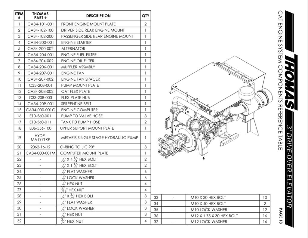
22
23 4 CUMMINS ENGINE SYSTEM COMPONENTS PAGE 0 ITEMS & 4 MOUNTED TO ENGINE HOOD SUPPORT
24 CUMMINS ENGINE SYSTEM COMPONENTS REFERENCE TABLE PAGE ITEM # THOMAS PART # DESCRIPTION QTY C FRONT ENGINE MOUNT C-0-00 REAR ENGINE MOUNT C ENGINE STARTER 4 C ALTERNATOR C ENGINE FUEL FILTER 6 C ENGINE OIL FILTER 7 C ENGINE FAN C FAN SPACER C-0-00 PUMP MOUNT PLATE 0 C-0-00 FLEX PLATE C-0-00 FLEX PLATE HUB C-0-00 V-BELT C IGNITION CONTROL BOX 4 C MAGNETIC SWITCH RELAY E PUMP TO T-VALVE HOSE 6 E PUMP TO BELT VALVES 7 E TANK TO PUMP E SUPPORT ROD HYDP- MA7TRP METARIS HYDRAULIC PUMP 0 ENG-C00 ENGINE ISOLATOR O-RING TO MALE JIC O-RING TO MALE JIC 0 - " X " HEX BOLT " X " HEX BOLT - " SAE WASHER " LOCK WASHER 7 - " NYLOCK NUT 4 - " X " HEX BOLT - " LOCK WASHER 0 - " HEX NUT - 4 " X 4 " HEX BOLT - 4 " FLAT WASHER 6-4 " NYLOCK NUT ITEM # THOMAS PART # DESCRIPTION QTY. 4 - M0 X. X 6CM HEX BOLT 4 - M0 X 0 HEX BOLT M0 X 40 HEX BOLT 7 - M0 LOCK WASHER 0 - M X 0 HEX BOLT - M LOCK WASHER 40 - /4" HEX NUT 4
25 CUMMINS ENGINE SYSTEM COMPONENTS CONT. PAGE ITEM # THOMAS PART # DESCRIPTION QTY C-0-00 COBRA 0 INTAKE ELBOW C-0-00 TURBO INTAKE PIPE C EXHAUST BRACKET 4 C in V-CLAMP C-06-0 EXHAUST PIPE 6 C-0-00 UPPER RADIATOR HOSE 7 C-0-00 LOWER RADIATOR HOSE AF0-000 DONALDSON AIR FILTER AF0-00 RUBBER REDUCER ELBOW 0 - " EXHAUST CLAMP - " EXHAUST FLAP - " HOSE CLAMP - " HOSE CLAMP 4 - " HOSE CLAMP - " HOSE CLAMP 6 - " HOSE CLAMP 7-4" HOSE CLAMP - M0 X.7 X 0 HEX BOLT - M0 LOCK WASHER
26 DONALDSON AIR FILTER PAGE *AF0-000 DOES NOT INCLUDE MOUNT STRAPS OR PRE-CLEANER ITEM THOMAS # PART # DESCRIPTION AF0-000 DONALDSON AIR FILTER* (P0000) AF0-00 P0 MAIN FILTER AF0-00 P40 INNER FILTER 4 AF0-00 INISIDE COVER AF0-004 CAP 6 AF0-00 CAP BAND 7 AF0-006 MOUNTING STRAP AF0-007 AIR FILTER BODY AF0-00 WING NUT 0 AF00-00 STAINLESS STEEL PRE-CLEANER AF00-00 RUBBER PRE-CLEANER BUSHING - 4 " HOSE CLAMP QTY
27 CAT ENGINE HOOD ASSEMBLY PAGE ITEM # THOMAS PART # DESCRIPTION QTY E ENGINE HOOD PANEL E ENGINE HOOD MOUNT E ENGINE HOOD MOUNT PLATE 4 CA EXHAUST MOUNT BRACKET - " PIPE CLAMP ASSEMBLY 6 - " X " HEX BOLT " LOCK WASHER - " FLAT WASHER 4 - " HEX NUT 0-4 " X 7 " HEX BOLT - 4 " X 4 " HEX BOLT - 4 " LOCK WASHER 7-4 " FLAT WASHER 4-4 " NYLOCK NUT 0 - M0 X.7 X 0 HEX BOLT M0 LOCK WASHER 4
28 CUMMINS ENGINE HOOD ASSEMBLY PAGE ITEM THOMAS # PART # DESCRIPTION E CU CUMMINS. ENGINE HOOD ASSEMBLY E CU CUMMINS ENGINE HOOD PANEL E CU ENGINE HOOD MOUNT FLANGE 4 E CU HOOD MOUNT PLATE E CU HOOD MOUNT BASE - NPA RUBBER ISOLATOR BOLT QTY 4 " X 4" HEX BOLT 7 4 " X " HEX BOLT 4 4 " FLAT WASHER 6 4 " LOCK WASHER 7 4 " HEX NUT 4 " NYLOCK - M0 X.7 X 0 HEX BOLT - M0 LOCK WASHER
29 RADIATOR, OIL COOLER, AND DUST SCREEN PAGE ITEM # THOMAS PART # DESCRIPTION QTY C-0-00 RADIATOR E RADIATOR CAP E DUST SCREEN HINGE 4 E DUST SCREEN ASSEMBLY HYDOC-00 OIL COOLER 6 HYDOC-0 OIL COOLER MOUNT BUSHING 4 7 E OIL COOLER MOUNT PLATE E OIL COOLER TO TANK E MAIN VALVE TO OIL COOLER 0 - O-RING TO MALE JIC 0 (06-) - O-RING TO MALE JIC (070-) - " X 4" PANHEAD SCREW - 4" X " PANHEAD SCREW 4-4 " X 4" HEX BOLT 4 4" X 4" HEX BOLT 4 6-4" FLAT WASHER LOCK WASHER - 4 " HEX NUT - 4" NYLOCK " FLAT WASHER 4-6 " LOCK WASHER - 6 " HEX NUT - 6 " JAM NUT
30 CAT RADIATOR SHROUD ASSEMBLY PAGE ITEM THOMAS # PART # DESCRIPTION QTY E BOTTOM RADIATOR MOUNT E ENGINE FAN GUARD E RADIATOR OVERFLOW TANK ASSEMBLY 4 E LATCH MOUNT WJ-0 RUBBER LATCH KIT 6 - " CABLE CLAMP 7 - " X 4 " HEX BOLT 4 - " FLAT WASHER - " LOCK WASHER " HEX NUT 4-6 " X 7 " HEX BOLT - 6 " FLAT WASHER - 6 " LOCK WASHER 4-6 " HEX NUT - 4 " X 4 " HEX BOLT 6-4 " FLAT WASHER 7-4 " LOCK WASHER - 4 " SAE WASHER - 4 " HEX NUT
31 CUMMINS RADIATOR SHROUD ASSEMBLY PAGE ITEM THOMAS # PART # DESCRIPTION QTY E BOTTOM RADIATOR MOUNT E ENGINE FAN GUARD E RADIATOR OVERFLOW TANK ASSEMBLY 4 E CU LATCH MOUNT WJ-0 RUBBER LATCH KIT " X 4 " HEX BOLT 4 " FLAT WASHER " LOCK WASHER 4 " HEX NUT 4 4 " X 4 " HEX BOLT 4 " FLAT WASHER 4 " LOCK WASHER 4 " SAE WASHER 4 " HEX NUT
32 FUEL TANK ASSEMBLY PAGE ITEM THOMAS # PART # DESCRIPTION E FUEL TANK E TANK SHOCK ABSORBER FTC-00 FUEL TANK CAP 4 - MALE INLINE HOSE FITTING (47-4) - INLINE FUEL FILTER - NAPA GOLD INLINE FUEL FILTER HOSE CLAMP QTY 6 " X 4" HEX BOLT 4 6 " FLAT WASHER 6 " LOCK WASHER 4 6 " HEX NUT 4
33 HYDRAULIC OIL TANK PAGE ITEM # THOMAS PART # DESCRIPTION QTY. E HYDRAULIC TANK ASSEMBLY E TANK SHOCK ABSORBER HTC-00 HYDRALIC TANK CAP 4 HYDF-SE0A ZINGA SE-0 HYDRAULIC FILTER BODY HYDF-SE0 ZINGA SE-0 HYDRAULIC FILTER 6 SSTM- 4" FLOW EASY SUCTION SCREEN 7 - MALE PIPE TO MALE PIPE (0-6) - MALE PIPE TO MALE JIC BRANCH (00-) - MALE PIPE TO FEMALE PIPE RUN (0-6) 0 - MALE PIPE TO MALE JIC BRANCH (00-) - MALE PIPE TO MALE JIC RUN (0-) - BELT VALVE TO TANK FILTER TEE - OIL COOLER TO TANK FILTER TEE 4 - UPPER BELT RETURN PIPE TO TANK - TANK TO PUMP SUCTION " MALE TO FEMALE 0 ELBOW 7-6" X - 4" HEX BOLT - 6" X " HEX BOLT - 6" FLAT WASHER 0-6" LOCK WASHER 4-6" HEX NUT 4
34 0 6 HANDLE KIT HYDV-PC660 NOT INCLUDED IN STANDARD HANDLE KIT ITEM THOMAS # PART # DESCRIPTION QTY. E VALVE TO STEER CYL BUTT END E VALVE TO FRONT LIFT CYL. BUTT TEE E VALVE TO STEER CYL ROD END 4 E VALVE TO FRONT LIFT CYL. ROD TEE E VALVE TO HOOD CYL. PIPES 6 E VALVE TO NEAR FLAP CYL ROD END 7 7 E VALVE TO NEAR FLAP CYL BUTT END E VALVE TO FAR FLAP CYL ROD END E VALVE TO FAR FLAP CYL BUTT END 0 E VALVE TO FRONT DRIVE SOLENOID E VALVE TO FRONT DRIVE SOLENOID E VALVE TO BELT VALVE CONNECTION E VALVE TO OIL COOLER 4 E VALVE TO REAR LIFT TEE E VALVE TO REAR DRIVE 6 HYDV- PC660 REPLACMENT HANDLE KIT O-RING TO MALE JIC O-RING TO MALE JIC O-RING TO MALE JIC MAIN CONTROL VALVE ASSEMBLY PAGE
35 CROSS VALVE ASSEMBLIES PAGE FRONT VALVE ASSEMBLY 7 REAR VALVE ASSEMBLY ITEM # THOMAS PART # DESCRIPTION QTY. HYDV-C64 CROSS CONTROL VALVE - DETENT - HYDV-C00 CROSS VALVE SEAL KIT (NOT SHOWN) HYDV-PCO PARKER C00S CHECK VALVE MALE PIPE TO JIC BRANCH TEE O-RING TO JIC O-RING TO JI C O-RING TO JI C O-RING TO MALE JIC O-RING TO JIC O-RING TO JIC BRANCH TEE 0 - FF- O-RING PLUG
36 4 6 7 PAGE HYDRAULIC PIPES, CLAMPS AND HOSES ITEM # THOMAS PART # DESCRIPTION QTY. E A MOTOR HYDRAULIC PIPE ASSEMBLY E B HOOD HYDRAULIC PIPE ASSEMBLY E UPPER HYDRAULIC PIPE MOUNT ASSEMBLY 4 DOL0 UPPER HOOD CYLINDER (BUTT END) DOL0 UPPER HOOD CYLINDER (ROD END) 6 DOL6 UPPER MOTOR RETURN 7 DOL7 UPPER MOTOR PRESSURE DOL0 UPPER HOOD TO PIPES DOL0 MOTOR PIPE TO VALVE
37 0 7 HYDRAULIC SCHEMATIC PAGE 4 J 7 C D E F J 6 L P 0 T S O N K B V U M H 6 G Q R H A
38 ITEM THOMAS # PART # DESCRIPTION QTY. E PIPE TO HOOD CYL BUTT END E VALVE TO STEER CYL. BUTT END E PIPE TO HOOD CYL ROD END 4 E VALVE TO FRONT LIFT CYL. TEE BUTT END E FRONT LIFT CYL BUTT END CONNECTION 6 E VALVE TO STEER CYL. ROD END 7 E VALVE TO FRONT LIFT CYL. TEE ROD END E FRONT LIFT CYL ROD END CONNECTION E MAIN VALVE TO HOOD CYL PIPES 0 E VALVE TO NEAR SIDE FLAP CYL. ROD END E VALVE TO NEAR SIDE FLAP CYL. BUTT END E VALVE TO FAR SIDE FLAP CYL. ROD END E VALVE TO FAR SIDE FLAP CYL. BUTT END 4 E VALVE TO FRONT DRIVE SOLENOID BLOCK E VALVE TO FRONT DRIVE SOLENOID BLOCK 6 E BELT VALVE TO BELT VALVE CONNECTION 7 E MAIN VALVE TO BELT VALVE CONNECTION E PUMP TO BELT VALVE TEE E OIL COOLER TO TANK FILTER TEE 0 E FRONT DRIVE SOLENOID TO DRIVE MOTOR E FRONT DRIVE SOLENOID TO DRIVE MOTOR E MAIN VALVE TO OIL COOLER E BELT VALVE TO LOWER DRIVE MOTOR 4 E BELT VALVE TO BELT VALE TEE CONNECTION E UPPER BELT RETURN PIPE TO TANK FILTER 6 E UPPER BELT MOTOR TO RETURN PIPE 7 E UPPER BELT PRESSURE PIPE TO MOTOR E BELT VALVE TO TANK FILTER TEE E BELT VALVE TO UPPER BELT PRESSURE PIPE 0 E PUMP TO BELT VALVES E LOWER BELT MOTOR RETURN TO TANK FILTER E TANK TO PUMP SUCTION E FRAME TEE TO REAR LIFT CYL ROD ENDS 4 E FRAME TEE TO REAR LIFT CYL BUTT ENDS E MAIN VALVE TO REAR LIFT CYL TEES 6 E QUICK CONNECTIONS TO REAR DRIVE MOTOR 7 E VALVE TO REAR DRIVE QUICK CONNECTIONS A E MAIN CONTROL VALVE ASSEMBLY B E HYDRAULIC TANK ASSEMBLY C UPPER BELT MOTOR PIPE E A D LOWER BELT MOTOR PIPE E UPPER HOOD CYLINDER PIPE E B F LOWER HOOD CYLINDER PIPE G HYDV-C64 BELT CONTROL CROSS VALVE H HYDM-TE00 GROUND DRIVE MOTORS J HYDM-TF047 UPPER AND LOWER BELT MOTORS K SPLASH FLAP LIFT CYLINDERS HYDTR-00 L HOOD CYLINDERS M HYDTR-0 FRONT GROUND DRIVE STEERING CYLINDER N FRONT GROUND DRIVE LIFT CYLINDER HYDTR-0 O REAR GROUND DRIVE LIFT CYLINDER P HYDP-MA7TR METARIS THREE STAGE HYDRAULIC PUMP Q HYDBC-PR0 CROSS PORT PRESSURE RELIEF R HYDBC-PR0 CROSS PORT PRESSURE RELIEF BLOCK S HYDF-SE0 HYDRAULIC FILTER T HYDOC-00 OIL COOLER U NV--F 4" HOSE QUICK CONNECTOR, FEMALE V NV--M 4" HOSE QUICK CONNECTOR, MALE HYDRAULIC SCHEMATIC REFERENCE TABLE PAGE
39 NOTES: PAGE 6
40 NOTES: PAGE 7
41 INDEX PART # DESCRIPTION PAGE # PART # DESCRIPTION PAGE # 00BR-T-4 T x -½ SPROCKET FLOATER,0 00BS-T-4 T x -½ SPROCKET KEYED,0 00BS-T-4 T x -½ SPROCKET,0 60BS-6T-6 60BS x 6T x SPROCKET AF00-00 STAINLESS STEEL PRE-CLEANER AF00-00 RUBBER PRE-CLEANER BUSHING AF0-000 DONALDSON AIR FILTER,, AF0-00 DONALDSON MAIN FILTER AF0-00 DONALDSON INNER FILTER AF0-00 INSIDE COVER AF0-004 CAP AF0-00 CAP BAND AF0-006 MOUNTING STRAP AF0-007 AIR FILTER BODY AF0-00 WING NUT AF0-00 RUBBER REDUCER ELBOW, B0-0 LCD DASH DISPLAY BR-FL0A -¼ FLANGE BEARING BR-PB ¾ PILLOW BLOCK BEARING 7 BR-PB6 PILLOW BLOCK BEARING BR-PB -⅛ PILLOW BLOCK BEARING, BR-PB0A -¼ PILLOW BLOCK BEARING 7 BR-PB4 -½ PILLOW BLOCK BEARING 6, C FRONT ENGINE MOUNT,0 C-0-00 REAR ENGINE MOUNT,0 C ENGINE STARTER,0 C ALTERNATOR,0 C ENGINE FUEL FILTER,0 C ENGINE OIL FILTER,0 C-0-00 CODRA 0 INTAKE ELBOW C-0-00 TURBO INTAKE PIPE C EXHAUST BRACKET C EXHAUST PIPE C ENGINE FAN 0, C ENGINE FAN SPACER 0, C-0-00 PUMP MOUNT PLATE 7,,0, C-0-00 FLEX PLATE, C-0-00 FLEX PLATE HUB 7,,0, C-0-00 V-BELT 0, C-0-00 UPPER RADIATOR HOSE C-0-00 LOWER RADIATOR HOSE C IGNITION CONTROL BOX 0, C MAGNETIC SWITCH RELAY 0, C V-CLAMP CA C ENGINE COMPUTER 7, CA M COMPUTER MOUNT PLATE 7, CA FRONT ENGINE MOUNT PLATE 7, CA DRIVER REAR ENGINE MOUNT 7, CA PASSENGER REAR ENGINE MOUNT 7, CA EXHAUST MOUNT BRACKET 4 CA ENGINE STARTER 7, CA ALTERNATOR 7, CA ENGINE FUEL FILTER 7, CA ENGINE OIL FILTER 7, CA TURBO INTAKE COUPLER CA INTAKE COUPLER CA TURBO INTAKE HOSE (SMALL) CA AIR SENSOR CA MUFFLER ASSEMBLY 7, CA EXHAUST PIPE CA ENGINE FAN 7, CA ENGINE FAN SPACKER 7, CA CAT FLEX PLATE 7, CA SERPENTINE BELT 7, CA UPPER RADIATOR TUBE CA LOWER RADIATOR TUBE CA UPPER RADIATOR TUBE COUPLER CA UPPER RADIATOR HOSE CA LOWER RADIATOR HOSE A CA LOWER RADIATOR HOSE B CA RADIATOR OVERFLOW HOSE CPL-0-4 -¼ x -½ SPLIT COLLAR 6, E TANK SHOCK ABSORBER,0 E PUMP TO VALVE HOSE 0, E PUMP TO BELT VALVE 0, E TANK TO PUMP 0, E CHAIN SEAL RUBBER 4 E CHAIN SEAL RUBBER BACKER 4 E TAKE-UP END PLATE E TAKE-UP BEARING MOUNT E LOWER TAKE-UP ADJUSTER E HITCH ASSEMBLY 4 E HITCH BRACE BAR 4 E LOWER TAKE-UP SHAFT ASM,,0 E LOWER TAKE-UP SHAFT,0 E SPLASH FLAP PLATE & HINGE 4 E SPLASH FLAP RUBBER 4 E CHAIN SEAL RUBBER BACKER 4 E COMPLETE UHMW WEARSTRIP KIT E UHMW CHAIN ALIGNMENT PADS E LOWER CHAIN MOTOR MOUNT 6 E HOLDER DOWN ROLLER,,0 E ROLLER REPLACMENT BEARING,0 E DRIVER INCLINE COVER PAN E INCLINE COVER ACCESS PANEL E PASSENGER INCLINE COVER PAN E UPPER TAKE-UP BEARING PAD 7 E UPPER TAKE-UP ADJUSTER 7 E PIT BELT SEAL 7 E PIT BELT SEAL BACKER 7 E LOWER DRIVE ROLLER ASSEMBLY 6,,0 E LOWER DRIVE ROLLER SHAFT,0 E CONE SEAL RUBBER 6 E DRIVER CONE SEAL MOUNT 6 E PASSENGER CONE SEAL MOUNT 6 E PIT SEAL FLAP 7 E PIT BRUSH 7 E EMERGENCY KILL SWITCH E STANLESS STEEL OVERLAY KIT 7 E SWEEPER BRUSH 7 E UPPER DRIVE ROLLER,,0 E UPPER DRIVE ROLLER SHAFT,0 E SNUB ROLLER ASSEMBLY,,0 E CLEATED SNUB ROLLER,0 E UPPER RETURN ROLLER 7,,0 E CLEATED UPPER RETURN ROLLER,0 E UPPER TAKE-UP ROLLER 7,,0 E06-6STBC x LOWER BELTED CHAIN 0 E06-6STBZ x 6 6 STANDARD UPPER BELT 0
42 INDEX PART # DESCRIPTION PAGE # PART # DESCRIPTION PAGE # E AXLE ASSEMBLY 4 E AXLE TUBE 4 E FUEL TANK E BOTTOM RADIATOR MOUNT 7, E ENGINE FAN GUARD 7, E RADIATOR 6 E RADIATOR CAP 6 E RADIATOR OVERFLOW ASSEMBLY 7, E DUST SCREEN HINGE 6 E LATCH NOUNT 7, E CAT ENGINE HOOD 4 E CU CUMMINS. ENGINE HOOD E CAT ENGINE HOOD PANEL 4 E CU CUMMINS ENGINE HOOD PANEL E CAT ENGINE HOOD MOUNT 4 E CU CUMMINS ENGINE HOOD FLANGE E CAT ENGINE HOOD MOUNT PLATE 4 E CU CUMMINS HOOD MOUNT PLATE E CU CUMMINS HOOD MOUNT BASE E ENGINE CONTROL BOX E CAT CONTROL BOX FACE E CU CUMMINS CONTROL BOX FACE E HYDRAULIC TANK ASSEMBLY 0,4, E MAIN CONTROL VALVE ASSEMBLY 4, E A MOTOR HYDRAULIC PIPE,,4, E B UPPER HOOD CYLINDER PIPE,,4, E UPPER HYDRAULIC PIPE MOUNT E TORQUE ARM 6, E UPPER SUPPORT PLATE 7, E OIL COOLER MOUNT PLATE 6 E HOOD CYLINDER PRESSURE,4, E VALVE TO STEERING CYLINDER,,4, E VALVE TO FRONT LIFT CYLINDER,4, E FRONT LIFT CYLINDER BUTT TEE 4, E VALVE TO STEERING CYL ROD,,4, E FRONT COVER SEAL E VALVE TO FRONT LIFT CYLINDER,4, E FRONT LIFT CYLINDER ROD,6 E VALVE TO HOOD CYL PIPES,4, E VALVE TO NEAR SIDE FLAP ROD,4, E VALVE TO FAR SIDE FLAP BUTT,4, E VALVE TO FAR FLAP CYL ROD,4, E VALVE TO FAR FLAP CYL BUTT,4, E VALVE TO FRONT DRIVE SOL,4, E VALVE TO FRONT DRIVE SOL,4, E VALVE TO BELT VALVE HOSE,6 E VALVE TO BELT VALVE,4, E PUMP TO BELT VALVE TEE 4, E OIL COOLER TO TANK FILTER TEE 7,,6 E FRONT DRIVE SOL DRIVE MOT P 4, E FRONT DRIVE SOL DRIVE MOT R 4, E VALVE TO OIL COOLER 6,,4, E BELT VALVE TO LOWER DRIVE MOT 6,4, E BELT VALVE TO BELT VALVE TEE 4, E UPPER BELT RETURN PIPE FILTER 4, E UPPER BELT MOTOR TO RETURN,4, E UPPER BELT PRESSURE PIPE,4, E BELT VLAVE TO TANK FILTER TEE 4, E BELT VALVE TO UPPER PRESSURE 4, E PUMP TO BELT VALVES 4, E LOWER BELT MOTOR RETURN 6,4, E TANK TO PUMP SUCTION 4, E FRAME TEE TO REAR LIFT ROD 4, E FRAME TEE TO REAR LIFT BUTT 6,7 E MAIN VALVE TO REAR LIFT CYL,4, E QUICK CONNECTIONS TO DRIVE 4, E VALVE TO REAR DRIVE QUICK CON,4, E A GROUND DRIVE YOKE REAR LIFT E A/B DRIVE YOKE ASSEMBLY E B GROUND DRIVE YOKE FRONT LIFT E CHAIN GUARD E DRIVE AXLE ASSEMBLY E DRIVE CHAIN E YOKE PIVOT LOCK ASSEMBLY, E CASTER YOKE ASSEMBLY E CASTOR AXLE ASSEMBLY E STEERING YOKE PIVOT LINK E STEERING YOKE TIE ROD E DUST SCREEN ASSEMBLY 6 E DRIVER SIDE REAR LIFT INNER E DRIVER SIDE REAR LIFT OUTER E SUPPORT ROD 0, E PUMP TO VALVE HOSE 7, E TANK TO PUMP HOSE 7, ECG-00 WATER TEMP GAGE ECG-004 OIL PRESSURE GAGE ECG-00 HOUR METER ECG-006 VOLT METER ECL-00G GREEN INDICATOR (GLOW PLUG) ECL-00R RED INDICATOR (FUEL FILTER) ECS-00 INGITION SWITCH ECS-00 BLACK BUTTON SWITCH ECS-00 MOMENTARY SWITCH (THROTTLE) ECS-006 TOGGLE SWITCH (THROTTLE) ENG-C00 ENGINE ISOLATOR 0, FTC-00 FUEL TANK CAP H0-000 LUG HUB COMPLETE ASSEMBLY -4 H0-00 SPINDLE (WELD TO AXLE TUBE) 4 H0-00 DUST SEAL -4 H0-00 OUTER WHEEL BEARING -4 H0-004 INNER WHEEL BEARING -4 H0-00 SPINDLE WASHER -4 H0-006 DUST CAP -4 H0-00 LUG HUB ASSEMBLY -4 H0-0 LUG HUB -4 H0-0 INNER BEARING RACE -4 H0-0 OUTER BEARING RACE -4 HTC-00 HYDRAULIC TANK CAP 0 HYDBC-PR0 CROSS PORT PRESSURE RELIFE 4, HYDBC-PR0 CROSS PORT PRESSURE BLOCK 4, HYDF-SE0 ZINGA HYDRAULIC FILTER 0,4, HYDF-SE0A ZINGA HYDRAULIC FILTER BODY 0,4, HYDM-TE0 GROUND DRIVE MOTOR,4, HYDM-TF040 LOWER BELTED CHAIN DRIVE MOT 6,4, HYDM-TF047 UPPER/LOWER BELTED CHAIN MOT,4, HYDOC-00 OIL COOLER 6,4, HYDOC-0 OIL COOLER MOUNT BUSHING 6 HYDP- MA7TRP METARIS SINGLE STAGE PUMP 7-,4, HYDTR-00 SPLASH FLAP LIFT CYLINDERS 4,
43 INDEX PART # DESCRIPTION PAGE # PART # DESCRIPTION PAGE # HYDTR-00 HOOD CYLINDER,4, HYDTR-0 GROUND DRIVE STEERING CYL,4, HYDTR- FRONT LIFT CYLINDER 4, HYDTR-0 GROUND DRIVE LIFT CYLINDER,4, HYDV-C00 CROSS VALVE SEAL KIT HYDV-C64 BELT CONTROL CROSS VALVE HYDV-PC0 PARKER CHECK VALVE NV--F ¾ QUICK HOSE CONECTOR F 4, NV--M ¾ QUICK HOSE CONECTOR M 4, SC-4 -½ SET COLLAR 0 SSTM- ¼ FLOW EASY SUCTION SCREEN 0 TC0 0FT THROTTLE CABLE TL TAPPER LOCK 0 WJ-0 RUBBER LATCH 7,
44 Thomas Manufacturing Co. LLC Drive Over Loader Manual October 0 Edition
1308 West 8th Avenue, Chico CA, Website:
 0 West th Avenue, Chico CA, Website: www.thomaswelding.com Phone: (0) -0 Email: info@thomaswelding.com Fax: (0) - parts@thomaswelding.com 0 ELEVATOR SERIAL NUMBER: TABLE OF CONTENTS IV Safety First...
FERTILIZER ELEVATOR SERIAL #
 FERTILIZER ELEVATOR SERIAL # TABLE OF CONTENTS SAFETY FIRST... IMPORTANT ORDERING INFORMATION... FERTILIZER ELEVATOR BREAKDOWN... LOWER SECTION... '-" & '-" HITCH ASSEMBLY... TRANSITION SECTION... DRIVE
Website:
 08 West 8th Avenue, Chico CA, 996 Phone: (0) 89-890 Fax: (0) 89-96 Website: www.thomaswelding.com Email: info@thomaswelding.com parts@thomaswelding.com PRE-CLEANER SERIAL DUMP CART TABLE OF CONTENTS SAFETY
Website:
 0 West th Avenue, Chico CA, Phone: (0) -0 Fax: (0) - Website: www.thomaswelding.com Email: info@thomaswelding.com parts@thomaswelding.com NUT BANKOUT SERIAL NUMBER: TABLE OF CONTENTS Safety First...
CONVEYORCART. Phone:( 530) )
 )") MANUF ACT URI NGCO.,L. L. C. CONVEYORCART 08West8t havenue,chi coca,9926 Phone:( 0)898940 Fax: ( 0)892946 Websi t e: www. ThomasWel di ng. com Emai l :i nf o@thomaswel di ng. com par t s@thomaswel di ng.
MANUF ACT URI NGCO.,L. L. C. CONVEYORCART 08West8t havenue,chi coca,9926 Phone:( 0)898940 Fax: ( 0)892946 Websi t e: www. ThomasWel di ng. com Emai l :i nf o@thomaswel di ng. com par t s@thomaswel di ng.
Retriever 5100G/P. 11/89 revised 10/02 FORM NO
 Retriever 5100G/P PARTS LIST Advance MODELS 56497000, 56497010 This parts list is for machines after serial number 353005 All models covered in this manual are OBSOLETE 11/89 revised 10/02 FORM NO. 56042216
Retriever PARTS LIST Advance MODEL 5200G(OBSOLETE)
") Retriever PARTS LIST Advance MODEL 5200G(OBSOLETE) 5/85 revised 2/01 FORM NO. 56042131 TABLE OF CONTENTS DESCRIPTION PAGE OUTER BODY...1-2 HYDRAULIC PUMP, ENGINE & FUEL TANK...3-4 HYDRAULIC OIL FILTER,
Retriever PARTS LIST Advance MODEL 5200G(OBSOLETE) 5/85 revised 2/01 FORM NO. 56042131 TABLE OF CONTENTS DESCRIPTION PAGE OUTER BODY...1-2 HYDRAULIC PUMP, ENGINE & FUEL TANK...3-4 HYDRAULIC OIL FILTER,
DIAMOND CONCRETE SAW PARTS LIST MODEL CC8000 P R O D U C T S. (Revised )
") DIAMOND P R O D U C T S CONCRETE SAW PARTS LIST MODEL CC8000 (Revised 10-15-2002) Table of Contents Page Saw Controls Legend. 3 Drawing 1. Frame Group. 4-5 Drawing 2. Arm Assembly... 6-7 Drawing 3. Hydraulics
DIAMOND P R O D U C T S CONCRETE SAW PARTS LIST MODEL CC8000 (Revised 10-15-2002) Table of Contents Page Saw Controls Legend. 3 Drawing 1. Frame Group. 4-5 Drawing 2. Arm Assembly... 6-7 Drawing 3. Hydraulics
Retriever 5800G/P/D. revised 2/01 Form Number
 Retriever 5800G/P/D PARTS LIST Advance MODELS 56482005, 56482010, 56482015 This parts list is for machines after serial number 221134 All models covered in this manual are OBSOLETE revised 2/01 Form Number
DEBRIS BLOWER 2613 BLOWER ASSEMBLY PARTS CATALOG MODEL NO & UP. The TORO Company All Rights Reserved. FORM NO Rev.
 FORM NO. 01-505-0440 Rev. D MODEL NO. 44520-20101 & UP PARTS CATALOG DEBRIS BLOWER 2613 Part 1 61-005-0073 Hitch & Lower Housing 1 2 61-005-0121 Fan Housing 1 3 61-005-0061 Fan Assembly 1 4 01-113-0070
72K850ZP PARTS MANUAL
 7 2 K 8 5 0 Z P PARTS MANUAL 72 MID-CUT GAS ENGINE OPTION SECTION 72 MID-CUT DECK ASSEMBLY 72" Mid-Cut Deck Assembly # PART NO. QTY DESCRIPTION 1 582096 1 72" MC DECK WELDMENT 2 582098 1 72" DECK CHANNEL
Boxer 532DX Parts Manual
 BIG POWER IN ALL PLACES Boxer 5DX Parts Manual SN and Higher Part No. 5- Phone: Sales - 00--00, Parts and Service - 00-55- www.boxerequipment.com Manufactured by: Morbark, Inc. 50 S. Winn Rd., P.O. Box
TransLift TL 2550K Parts Manual
 TransLift TL 2550K Parts Manual Tink, I nc. 2361 D urham Dayton H w y D urham, C A 95938 Toll Free 888-367-8465 Fax 530-895-0751 w w w.tink inc.co ṁ Table of Contents Full Assembly View... 2 Tank View...
RITE WAY MFG. CO. LTD. P.O.
 CO. LTD. P.O. Box 328 Imperial, Saskatchewan Canada, S0G 2J0 Ph: (306) 963-280 Fax: (306) 963-2660 Web Site: www.ritewaymfg.com E-mail: info@ritewaymfg.com Table of Contents SPECIFICATIONS... WARNING...2
250P Manure Spreader
 0P Manure Spreader Illustrated Parts Breakdown Page - Page Page Page Page Page Page Page Page Page Page Page Page Page Page - Page Page Page 0 Complete Front End PTO/Jack/Hitch Assembly Front Pulley Assembly
Pavement Services, Inc.
 MG68 Parts Manual Pavement Services, Inc. Page 30 29 30 29 25 25 24 30 4 26 29 4 25 26 4 Page 2 The Decal Kit for the Model MG68 Maintainer is Item Part # Description 056859 DECAL, ANTI-FREEZE (BLACK)
INFEED HOPPER COMPONENTS. Parts may not be exactly as shown. Bandit. Copyright 1/12
 INFEED HOPPER COMPONENTS 80 INFEED HOPPER COMPONENTS 1. 626-200019 Folding Pan for Infeed Hopper 2 a. 900-4901-83 Folding Pan Spring Lock & Trap Door Lock b. 900-7900-93 Black Rubber Cap (Not Shown) 3
PARTS MANUAL THIS PAGE INTENTIONALLY LEFT BLANK. Ag-Bag International, Ltd. G7000 June Appendix A
 The parts manual is organized into groups, it is designed to make the locating of parts easier. The exploded drawings also show assembly paths. All parts listed are available from your authorized Ag-Bag
REAR ENGINE RIDER 42 MOWER SERIES 22
 Parts Manual for REAR ENGINE RIDER MOWER SERIES MODELS 1BVE CONTENTS DESCRIPTION PAGE(S) DESCRIPTION PAGE(S) WHEELS- TIRES... - FRONT END, STEERING.... - MAIN CASE... - DIFFERENTIAL, R. H. FENDER... 8-9
Boxer 700HDX Parts Manual
 BIG POWER IN ALL PLACES Phone: Sales - 800-831-0042, Parts and Service - 800-255-8839 www.boxerequipment.com Boxer 700HDX Parts Manual SN 5082 and Higher Part No. 76345-820 Manufactured by: Morbark, LLC.
OPERATOR S MANUAL MAINTENANCE MANUAL PARTS LIST TURFCO CR-7. Broadcast Top Dresser. Product Number Starting Serial Number P00851
 OPERATOR S MANUAL MAINTENANCE MANUAL PARTS LIST TURFCO CR- Broadcast Top Dresser Product Number 0 Starting Serial Number P00 US Patent,,0,,0, and,, Manual Number DANGER - IF INCORRECTLY USED THIS MACHINE
Hydrostatic Zero-Turn Commercial Riding Mower
 Hydrostatic Zero-Turn Commercial Riding Mower Professional Turf Equipment 0" Fabricated Deck ILLUSTRATED PARTS LIST TABLE OF CONTENTS Frame Assembly.................................. 3 0" Fabricated Cutter
Hydrostatic Zero-Turn Commercial Riding Mower
 Hydrostatic Zero-Turn Commercial Riding Mower Professional Turf Equipment 54" Fabricated Deck ILLUSTRATED PARTS LIST TABLE OF CONTENTS Frame Assembly.................................. 3 54" Fabricated
EUROPEAN REAR ENGINE RIDER SERIES 20
 Parts Manual for EUROPEAN REAR ENGINE RIDER SERIES 20 MODEL E281320BE E331520KVE McDonough, GA, 30253 U.S.A. Briggs & Startton Yard Power Products Group Copyright 2006 Briggs & Startton Corporation Milwaukee,
Parts Manual EZF 3417/ Please read the operator s manual carefully and make sure you understand the instructions before using the machine.
 Parts Manual EZF 3417/ 96579301 Please read the operator s manual carefully and make sure you understand the instructions before using the machine. English 200 HTC. All Rights Reserved. Beatrice, NE. Printed
REAR ENGINE RIDER EUROPEAN SERIES 22
 Parts Manual for REAR ENGINE RIDER EUROPEAN SERIES 22 MODELS E2822BE E2822BE E1522KVE CONTENTS DESCRIPTION PAGE(S) DESCRIPTION PAGE(S) WHEELS, TIRES...2, DRIVE DISC ASSEMBLY... 22 FRONT END, STEERING...4,
PARTS MANUAL. HD4SR and 12SR Auto Align Bale Skoop to 2017 K
 PARTS MANUAL 1998 to 2017 HD4SR and 12SR Auto Align Bale Skoop K34991-04 Table of Contents Section 1: Parts Breakdown...1-1 Bale Skoop Final Assembly... 1-2 Loader Assembly... 1-4 12SR - Grab Hook Assembly
Parts Manual for the Wright Z
 Parts Manual for the Wright Z Serial numbers 40581 & Higher Check www.wrightmfg.com for the latest revision Rev 9/2007 Shown with OPTIONAL Grass Collection System 2006 Wright Manufacturing Inc., All Rights
72B27LD PARTS MANUAL
 7 2 B 2 7 L D PARTS MANUAL 6 MID-CUT SECTION 6 MID-CUT DECK ASSEMBLY 25 24 23 26 22 00 20 9B SEE NOTE A 9A 75 34 6 2 87 98 05 03 2 90 2 68 53 93 02 69 5 49 5 7 8 0 0 9 36 88 8 58 97 3 46 59 3 72 92 76
MODEL S-32, 3200, ALL AMERICAN
 MODEL S-32, 3200, ALL AMERICAN 1. 1 3201-7001 Chassis Weldment 2. 1 3204-7010 Bell Crank Weld 3. 1 3204-7009 Seconday Lift Weld 4. 1 3204-2018 Primary Lift Arm 6. 1 340-3025-S0 Seat Spring 6. 3 847-2803
Parts manual MANUAL NO REV. 04 (12/14/00)
") Parts manual Models: 968999159 / ZTH5221KAA 968999160 / ZTH5223KAA 968999161 / ZTH5223KOA 968999162 / ZTH5223KOLA 968999163 / ZTH5225KOA 968999165 / ZTH6125KOA 968999166 / ZTH6125KAA 968999171 / ZTH6126KOA
Parts manual Models: 968999159 / ZTH5221KAA 968999160 / ZTH5223KAA 968999161 / ZTH5223KOA 968999162 / ZTH5223KOLA 968999163 / ZTH5225KOA 968999165 / ZTH6125KOA 968999166 / ZTH6125KAA 968999171 / ZTH6126KOA
Highline Manufacturing TopGun 1999 Page 1 A. TABLE OF CONTENTS... 1
 Highline Manufacturing TopGun 1999 Page 1 A. Table of Contents A. TABLE OF CONTENTS... 1 B. ASSEMBLY & INSTALLATIONS... 3 1. FLAIL DRUM ASSEMBLY... 3 2. FLAIL DRUM INSTALLATION... 4 3. FEED ROLLER ASSEMBLY...
Parts List for The 36 & 42 Wright Stander Mower (For Serial Numbers and Higher Until Superseded)
") Parts List for The & Wright Stander Mower (For Serial Numbers 00 and Higher Until Superseded) Replace with newer revisions as they become available 00 Wright Manufacturing, Inc. All rights reserved Revised:
Parts List for The & Wright Stander Mower (For Serial Numbers 00 and Higher Until Superseded) Replace with newer revisions as they become available 00 Wright Manufacturing, Inc. All rights reserved Revised:
52 MID-CUT DECK ASSEMBLY
 5 2 K 2 5 A PARTS MANUAL 52 MID-CUT SECTION 52 MID-CUT DECK ASSEMBLY 19 79 36 30 18 82 107 104 7 27 40 85 35 41 28 43 39 111 30 114 99 42 95 80 88 39 6 31 68 84 83 110 34 15 6 14 11 109 30 18 96 31 51
Mulching and Finishing Mowers MP and FP
 Mulching and Finishing Mowers MP and FP Parts Manual Locke Turf 0 Highway E, Opp, Alabama, () -00 Transport Wheel, Tire & Spindle MP and FP ALPHABETICAL INDEX CONTENTS PAGE 00 Hydraulic Cylinder (Rear)
Parts List for all Sentar Sport models For Sentar Sport serial #33615 and higher until superseded
 Parts List for all Sentar Sport models For Sentar Sport serial #33615 and higher until superseded WRIGHT MANUFACTURING, INC. - 4600X WEDGEWOOD BLVD - FREDERICK, MD 21703 Revised 01/2007 36" CUTTER DECK
42B350Z PARTS MANUAL
 4 2 B 3 5 0 Z PARTS MANUAL 64 56 68 2 48 45 30 47 62 26 38 7 35 33 65 43 42 6 16 26 40 31 1 23 14 5 16 19 36 21 20 27 28 24 26 66 22 44 28 29 28 68 34 30 29 32 39 13 17 14 15 12 5 3 4 57 55 54 61 59 60
Illustrated Parts & Packing List 528 Gandrud Road, Owatonna, MN For a complete distributor & dealer list go to
 Illustrated Parts & Packing List 528 Gandrud Road, Owatonna, MN 55060 For a complete distributor & dealer list go to www.gandy.net 66GW27F Orbit-Air Applicator 120 Cu. Ft. Hopper w/ 27 (2 ) Openings, Fertilizer
Retriever 5100G/P/D. 2/96 revised 10/02 Form Number
 Retriever 00G/P/D PARTS LIST Advance MODELS, 0, This parts list is for gas/propane machines after serial number 00 and diesel machines after serial number All models covered in this manual are OBSOLETE
BUSH HOG LAND MAINTENANCE REPAIR PARTS MANUAL MODEL: TD-1100 SECTION: 66
 BUSH HOG LAND MAINTENANCE REPAIR S MANUAL MODEL: TD-00 SECTION: 0 Griffin Ave. Selma, AL 0 () - () -00 Parts Ordering -00-0- Fax -00-- www.bushhog.com BUSH HOG/ LAND MAINTENANCE REPAIR S MANUAL JUNE, 00
LAND MAINTENANCE REPAIR PARTS MANUAL BUSH HOG MODEL: 307 SECTION: 16
 BUSH HOG LAND MAINTENANCE REPAIR S MANUAL MODEL: 0 SECTION: P.O. Box 0 Selma, AL 0-0 () - () -00 Parts Ordering -00-0- Fax -00-- www.bushhog.com BUSH HOG / LAND MAINTENANCE REPAIR S MANUAL SEPTEMBER, 0
Parts List for Sentar (For Serial Numbers Prior to 19729)
") Parts List for Sentar (For Serial Numbers Prior to 19729) Replace with newer revisions as they become available 2006 Wright Manufacturing, Inc. All rights reserved Updated 08/2006 52", 61" CUTTER DECKS
Parts List for Sentar (For Serial Numbers Prior to 19729) Replace with newer revisions as they become available 2006 Wright Manufacturing, Inc. All rights reserved Updated 08/2006 52", 61" CUTTER DECKS
TT4101 Rotary Tedder
 TT Rotary Tedder 0//0 Illustrated Parts Breakdown Page Page Page Page Page Page Page Page Page Page Page Tongue Assembly S/N S/N - Tongue Assembly S/N + Main Frame S/N - Main Frame S/N to Main Frame S/N
Drive End Bracket & Bearing. Drive End Bracket. Tandem Axle # #865733
 Drive End Bracket & Bearing #865089 1 06409700 1" Lock Collar 2 865733 Drive Bracket w/ Bearing 3 310037 End Drive Shaft Drive End Bracket #865733 1 03003100 Bearing 1" w/snap Ring 2 957795 Drive End Bracket
Parts List Wright Stander Rapid-Hite Mower (For Serial Numbers and Higher Until Superseded)
") Parts List Wright Stander Rapid-Hite Mower (For Serial Numbers 33615 and Higher Until Superseded) Replace with newer revisions as they become available 2007 Wright Manufacturing, Inc. All rights reserved
Parts List Wright Stander Rapid-Hite Mower (For Serial Numbers 33615 and Higher Until Superseded) Replace with newer revisions as they become available 2007 Wright Manufacturing, Inc. All rights reserved
2720/12720 PARTS MANUAL 72A SECTION FLEX WING ROTARY MOWER
 0/0 This Manual applies to models 0 and 0 that use a blade pan which measures. blade hole center to blade hole center. Also blades measure 8. from hole center to blade tip. See Section if these dimensions
EURO REEL
 Date Purchased Machine Serial No. Options The key number system in this parts book is arranged as follows: Please order parts by number - Key numbers with two circles denotes main assemblies. - Key numbers
Boxer 525DX Parts Manual
 BIG POWER IN ALL PLACES Boxer DX Parts Manual SN Part No. 3-13 Phone: Sales - 00-31-00, Parts and Service - 00--3 www.boxerequipment.com Manufactured by: Morbark, Inc. 0 S. Winn Rd., P.O. Box 00, Winn,
Please read the operator manual carefully and make sure you understand the instructions before using the machine.
 967327901-00 Parts Zero Manual Turn Mower Please read the operator manual carefully and make sure you understand the instructions before using the machine. When you need spare parts or support in service
PARTS MANUAL VR 1214 BALE KING V-RAKE GREEN AND YELLOW NUMBERS
 PARTS MANUAL VR 1214 BALE KING V-RAKE GREEN AND YELLOW NUMBERS MANUFACTURED BY: BRIDGEVIEW MANUFACTURING INC. P.O. BOX 4 GERALD, SASK. CANADA S0A 1B0 PHONE: (306) 745-2711 FAX: (306) 745-3364 TABLE OF
GSN-8 Spreader. Illustrated Parts Breakdown. Page 1 Front End Assembly Page 2 Axle Assembly Page 3 Floor & Apron Page 4 Pump Assembly
 GSN- Spreader Illustrated Parts Breakdown Page Front End Assembly Page Axle Assembly Page Floor & Apron Page Pump Assembly Page Hydraulics Page Manifold Components Page Manifold Cover Page Gearbox Components
Parts Manual for the Wright Z
 Parts Manual for the Wright Z Serial numbers 40581 & Higher Check www.wrightmfg.com for the latest revision Rev 6/2010 Shown with OPTIONAL Grass Collection System 2010 Wright Manufacturing Inc., All Rights
Parts List Wright Stander Rapid-Hite Mower (For Serial Numbers and Higher Until Superseded)
") Parts List Wright Stander Rapid-Hite Mower (For Serial Numbers 28551 and Higher Until Superseded) Replace with newer revisions as they become available 2006 Wright Manufacturing, Inc. All rights reserved
Parts List Wright Stander Rapid-Hite Mower (For Serial Numbers 28551 and Higher Until Superseded) Replace with newer revisions as they become available 2006 Wright Manufacturing, Inc. All rights reserved
6150 Power Sweeper. 5/06 revised 2/09 FORM NO
 6150 Power Sweeper OPTIONS PARTS LIST After Serial Number 630950 American-Lincoln Models: 576-500, 576-500CE, 576-502, 576-502CE, 576-503, 576-503CE, 576-504, 576-504CE, 576-505, 576-505CE, 576-506, 576-506CE,
Parts Manual MODEL B1WF2100
 Parts Manual MODEL BWF00 TABLE OF CONTENTS Control Panel CONTROLS- Pg. Control Panel-DECALS- Pg. Control Panel-HOSES- Pg. 9 Control Panel-TUBING- Pg. 8 Control Panel VALVES- Pg. Coupler Assembly Pg. 0
GRAIN DECK BELT CONVEYOR PARTS LIST SERIAL NOS
 GRAIN DECK BELT CONVEYOR PARTS LIST SERIAL NOS. 112000-115499 1 DISCHARGE ASSEMBLY - GRAIN BELT DRIVE OVER CONVEYOR SERIAL NOS. 112000-115499 2 REF # PART NO. DESCRIPTION QTY 1 C200760 Discharge Weldment
PARTS CATALOG
 R Ingersoll COMPACT TRACTORS WITH DIESEL ENGINES 3118D AND 4118D PARTS CATALOG 8-3310 PAINT ENGINES GENERAL INFO MODEL 3118D and 4118D COMPACT TRACTORS PRODUCT IDENTIFICATION NUMBERS (PIN) OR SERIAL NUMBERS
Parts Manual PZ Please read the operator manual carefully and make sure you understand the instructions before using the machine.
 Parts Manual PZ 60 967 045601-00 Please read the operator manual carefully and make sure you understand the instructions before using the machine. When you need spare parts or support in service questions,
Boxer 322D Parts Manual
 BIG POWER IN ALL PLACES Boxer D Parts Manual Serial No.s and Higher Part No. -80 Phone: Sales - 800-8-00, Parts and Service - 800--88 www.boxerequipment.com Manufactured by: Morbark, Inc. 80 S. Winn Rd.,
Retriever 360G/P. 5/92 revised 2/01 FORM NUMBER
 Retriever 360G/P PARTS LIST Advance MODELS 56468470, 56468480 This parts list is for machines after serial number 505073 All models covered in this manual are OBSOLETE 5/92 revised 2/01 FORM NUMBER 56042267
TT4100 Rotary Tedder
 TT0 Rotary Tedder Serial numbers 0 and higher Illustrated Parts Breakdown Page Page Tongue Assembly S/N - Tongue Assembly S/N to Page Page Page Page Page Tongue Assembly S/N to Tongue Assembly S/N + Main
Boxer 320 Parts Manual
 BIG POWER IN ALL PLACES Boxer 20 Parts Manual Serial No.s 9 & Higher Part No. 765-808 Phone: Sales - 800-8-002, Parts and Service - 800-255-889 www.boxerequipment.com Manufactured by: Morbark, Inc. 8507
FRONT RACK, BODY PANEL, AND HEADLIGHT ASSEMBLIES
 FRONT RACK, BODY PANEL, AND HEADLIGHT ASSEMBLIES 0747-506 1 2506-107 1 Rack, Front - Assembly (inc. 2) 2 0411-576 1 Decal, Warning - Load 3 0441-592 4 Bushing 4 8410-835 4 Screw, Cap 5 0423-669 4 Spacer
TT6101 Rotary Tedder
 TT0 Rotary Tedder 0/0/0 Illustrated Parts Breakdown Page Chassis Assembly Page Page Transport Axle Assembly S/N - Transport Axle Assembly S/N + Page Page Page Page Page Transport Lock Assembly Lift Frame
FLX15 ROTARY CUTTERS PARTS MANUAL ATENCIÓN! LEA EL INSTRUCTIVO
 Published: /0 FLX ROTARY CUTTERS S/N A00000 A0000 inclusive PARTS MANUAL Part No. A0-00P An Operators Manual with IMPORTANT Safety, Assembly, Operation and Maintenance information was packaged with this
Litter Spreader. Models SP400, SP450, SP500, SP550. Illustrated Parts Breakdown
 Litter Spreader Models SP00, SP0, SP00, SP0 Illustrated Parts Breakdown Page Front End Page Hydraulic System (w/ Side Mounted Reservoir) Page Hydraulic System (w/ Front Mounted Reservoir) Page Hydraulic
BUSH HOG LAND MAINTENANCE REPAIR PARTS MANUAL MODEL: 405 / 406 SECTION: 17
 BUSH HOG LAND MAINTENANCE REPAIR S MANUAL MODEL: 0 / 0 SECTION: 0 Griffin Ave. Selma, AL 0 () - () -00 Parts Ordering -00-0- Fax -00-- www.bushhog.com BUSH HOG/ LAND MAINTENANCE REPAIR S MANUAL SEPTEMBER,
TEREX Woodsman 730 BRUSH CHIPPER
 Woodsman 730 BRUSH CHIPPER Parts Manual Customer Dealer S/N Frame # Date Woodsman 150 Commerce Drive, Farwell MI 486 Phone: (800) 953-553 Fax: (989) 588-487 Flipper Discharge Chute Hand Crank Belt Shield
BUSH HOG LAND MAINTENANCE REPAIR PARTS MANUAL MODEL: 3414 SECTION: 67
 BUSH HOG LAND MAINTENANCE REPAIR S MANUAL MODEL: SECTION: 0 Griffin Ave. Selma, AL 0 () - () -00 Parts Ordering -00-0- Fax -00-- www.bushhog.com BUSH HOG/ LAND MAINTENANCE REPAIR S MANUAL July, 0 ROTARY
GTS150. Dune Buggy MINIMUM RECOMMENDED OPERATOR AGE: FOR OFF-ROAD USE ONLY. 10th letter in VIN: D-G
 0-06 GTS50 0th letter in VIN: D-G Dune Buggy MINIMUM RECOMMENDED OPERATOR AGE: 6 FOR OFF-ROAD USE ONLY This vehicle is designed and manufactured for off-road use only. USA only: It does not conform to
Illustrated Parts Manual. Model Number A2011ICS4BUSG (Green) A2011ICS4BOSG (Green - International)
 A2011ICS4BOSG (Green - International)") Illustrated Parts Manual 2 1 10 650 Model Number A2011ICS4BUSG (Green) A2011ICS4BOSG (Green - International) S H A R E O U R PAS S IO N. TM TABLE OF CONTENTS 2011 ATV 650 Green (Model No. A2011ICS4BUSG)
Illustrated Parts Manual 2 1 10 650 Model Number A2011ICS4BUSG (Green) A2011ICS4BOSG (Green - International) S H A R E O U R PAS S IO N. TM TABLE OF CONTENTS 2011 ATV 650 Green (Model No. A2011ICS4BUSG)
BUSH HOG LAND MAINTENANCE REPAIR PARTS MANUAL MODELS: RPM & RPM SECTION: 79
 BUSH HOG LAND MAINTENANCE REPAIR S MANUAL MODELS: -0 RPM & -000 RPM SECTION: 9 0 Griffin Ave. Selma, Al. 0 () - () -00 Parts Ordering -00-0- Fax -00-- www.bushhog.com April, 0 BUSH HOG/ LAND MAINTENANCE
SF90 Pmi Shifter 90cc Go Kart (VIN PREFIX LBFM)
") Page 1 of 23 Product Information Baja Web > Product Information > Parts Lists > GOKART > SF90 Pmi Shifter 90cc Go Kart (VIN PREFIX LBFM) SF90 Pmi Shifter 90cc Go Kart (VIN PREFIX LBFM) SF90 Pmi Shifter
Page 1 of 23 Product Information Baja Web > Product Information > Parts Lists > GOKART > SF90 Pmi Shifter 90cc Go Kart (VIN PREFIX LBFM) SF90 Pmi Shifter 90cc Go Kart (VIN PREFIX LBFM) SF90 Pmi Shifter
Lime Spreader. Model SL6. Illustrated Parts Breakdown. Front Hydraulics Rear Hydraulics Manifold Components. Spinner Assembly
 Lime Spreader Model SL Illustrated Parts Breakdown Page Page Page Page Page Page Page Page Page Page 0 Front End Front Hydraulics Rear Hydraulics Manifold Components Floor & Apron Axle Assembly Apron Drive
ATV 90 UTILITY GREEN (A2006KUB2BUSG) Page 1 of 60 AIR INTAKE ASSEMBLY
 Page 1 of 60 AIR INTAKE ASSEMBLY") 2006 ATV 90 UTILITY GREEN (A2006KUB2BUSG) Page 1 of 60 AIR INTAKE ASSEMBLY 2006 ATV 90 UTILITY GREEN (A2006KUB2BUSG) Page 2 of 60 AIR INTAKE ASSEMBLY Ref # Part Number Qty S/P/F Description 1 3303-005
2006 ATV 90 UTILITY GREEN (A2006KUB2BUSG) Page 1 of 60 AIR INTAKE ASSEMBLY 2006 ATV 90 UTILITY GREEN (A2006KUB2BUSG) Page 2 of 60 AIR INTAKE ASSEMBLY Ref # Part Number Qty S/P/F Description 1 3303-005
COMP C M O ACT COMPP C A T ACT Boxer Parts Manual
 Boxer Parts Manual Boxer Parts List.indd 1 6/9/06 11:04:01 AM Boxer Parts List.indd 2 6/9/06 11:04:02 AM Table of Contents Parts List and Illustrations Page Number Routine Maintenance Replacement Parts...iv
465606x692A Lawn Tractor (2001) Page 1 of 25 Drive Assembly
 Page 1 of 25 Drive Assembly") 465606x692A Lawn Tractor (2001) Page 1 of 25 Drive Assembly 465606x692A Lawn Tractor (2001) Page 2 of 25 Drive Assembly 1 26X249 Screw 2 095315 Knob, Parking Brake 3 711691 Nut, Push 4 1001217 Z Rod, Parking
465606x692A Lawn Tractor (2001) Page 1 of 25 Drive Assembly 465606x692A Lawn Tractor (2001) Page 2 of 25 Drive Assembly 1 26X249 Screw 2 095315 Knob, Parking Brake 3 711691 Nut, Push 4 1001217 Z Rod, Parking
PARTS CHASSIS AND HOOD
 MODEL 3xA CHASSIS AND HOOD 3 0 3 0 3 3 3 3 0 3 3 3 3 3 3 0 3 3 3 MODEL 3xA CHASSIS AND HOOD Seat 000 Cap, Push 0n 0x3 3 Spring 00 Screw x Bolt, Wing 000 Washer 0x Bolt, Shoulder 00x Support, Seat 0E00
Boxer 600HD Parts Manual
 Phone: Sales - 800-81-002, Parts and Service - 800-2-889 www.boxerequipment.com BIG POWER IN ALL PLACES Boxer 600HD Parts Manual SN 1 and Higher Part No. 76-821 Manufactured by: Morbark, LLC. 807 S. Winn
TT8101 Rotary Tedder
 TT0 Rotary Tedder Illustrated Parts Breakdown Page Front End Page Page Transport Axle Assembly Cylinder Linkage Page Guards Page Page Page Page Transport Lock Assembly Lift Frame Assembly Center Tunnel
Parts Manual Zero Turn Mower / Z 254i
 Parts Manual Zero Turn Mower / Z 254i 967324201-00 Please read the operator manual carefully and make sure you understand the instructions before using the machine. When you need spare parts or support
BUSH HOG LAND MAINTENANCE REPAIR PARTS MANUAL MODEL: 280 SERIES SECTION: 59
 BUSH HOG LAND MAINTENANCE REPAIR S MANUAL MODEL: 0 SERIES SECTION: P.O. Box 0 Selma, AL 0-0 () - () -00 Parts Ordering -00-0- Fax -00-- www.bushhog.com BUSH HOG/ LAND MAINTENANCE REPAIR S MANUAL JUNE,
TECHNICAL DATA BROCHURE ZTR 426
 TECHNICAL DATA BROCHURE ZTR 426 Date 8/84 IMPORTANT - READ OPERATOR'S MANUAL BEFORE OPERATION. Page 1 of 6 Seat Adjustment Loosen bolts on sliding bracket under each side of seat, slide seat forward or
Worldlawn Power Equipment, Inc. Industrial Park 2415 Ashland Ave. Beatrice, NE Toll Free Number:
 Parts Catalog R WYRZ46S/50U/60U Residential Zero Turn Mower Worldlawn Power Equipment, Inc. Industrial Park 2415 Ashland Ave. Beatrice, NE 68310 Toll Free Number: 1-800-267-4255 Table of Contents Table
LAWN TRACTORS ELECTRIC CLUTCH HYDRO DRIVE SERIES "G"
 Parts Manual for LAWN TRACTORS ELECTRIC CLUTCH HYDRO DRIVE SERIES "G" MODEL LT160H42GBV LT160H42GBV2 LT180H48GBV2 WLT160H42GBV WLT180H48GBV2 McDonough, GA, 30253 U.S.A. COPYRIGHT 2006 SNAPPER PRODUCTS,
ILLUSTRATED PARTS LIST
 IPL MODEL STHM 71 72 1 7 7 ILLUSTRATED PARTS LIST 70 2 7 THIS MANUAL CONTAINS THE ILLUSTRATED PARTS LIST FOR MODELS: STHM - 2CV with a serial number of 00001-0 SM-1A with a serial number of 001- SM-72A
HYDRAULIC ASSEMBLY (TE) MODELS: ,
 MODELS: ,") 6 HYDRAULIC ASSEMBLY (TE) 6 6 0 6 MODELS: 6, 60 0 0 0 0 0 0 6 0 6 HYDRAULIC ASSEMBLY (TE) MODELS: 6, 60........ FITTING, STRAIGHT, F600---0... 6..... FITTING, STRAIGHT... 6..... FITTING, F600-6-6-0........
6 HYDRAULIC ASSEMBLY (TE) 6 6 0 6 MODELS: 6, 60 0 0 0 0 0 0 6 0 6 HYDRAULIC ASSEMBLY (TE) MODELS: 6, 60........ FITTING, STRAIGHT, F600---0... 6..... FITTING, STRAIGHT... 6..... FITTING, F600-6-6-0........
MODEL x692A REPAIR PARTS HOOD & GRILL
 MODEL 0xA HOOD & GRILL 0 0 0 0 0 0 0 0 MODEL 0xA Screw x0 Dash 00 Trim. 00 Cable Hood Assemnly 00E00 Screw x Lens & Reflector Assembly Cap, Pivot 0 Bolt, Shoulder x 0 Base, Pivot 0 Brace, Right Grille
Lime Spreader. Model SL6. Illustrated Parts Breakdown. Front Hydraulics Rear Hydraulics Manifold Components. Spinner Assembly
 Lime Spreader Model SL Illustrated Parts Breakdown Page Page Page Page Page Page Page Page Page Page 0 Front End Front Hydraulics Rear Hydraulics Manifold Components Floor & Apron Axle Assembly Apron Drive
13AU609H063 (1999) Page 1 of 25 Axle & Wheels Front And Steering Assembly
 Page 1 of 25 Axle & Wheels Front And Steering Assembly") 13AU609H063 (1999) Page 1 of 25 Axle & Wheels Front And Steering Assembly 13AU609H063 (1999) Page 2 of 25 Axle & Wheels Front And Steering Assembly 1 683-0304 1 S Frame 2 710-0604A 1 /P Self-tapping Screw,
13AU609H063 (1999) Page 1 of 25 Axle & Wheels Front And Steering Assembly 13AU609H063 (1999) Page 2 of 25 Axle & Wheels Front And Steering Assembly 1 683-0304 1 S Frame 2 710-0604A 1 /P Self-tapping Screw,
PARTS MANUAL FOR BAD BOY ZT MODELS 2008
 PARTS MANUAL FOR BAD BOY ZT MODELS 00 hp Vanguard hp Briggs Seats and Tanks Transaxle Front Wheel Actuator Bar Engine/Clutch Steering Controls Battery/Actuator (Deck Lift) " Deck 0, 0" Deck, 0" Deck, Wiring
61 MID-CUT DECK ASSEMBLY
 6 1 K 2 8 A PARTS MANUAL A A 102 101 100 103 99 83 97 61 34 93 12 86 123 2 74 124 55 56 92 48 5 7 8 10 84 9 36 73 95 3 31 58 76 62 59 22 27 64 44 43 87 17 1 13 35 31 41 40 26 24 91 55 48 23 22 59 21 31
3 X2 4 X2 9 X1 6 DETAIL A H1064XT
 HXT AUGER, BASE MODEL, HXT 11 A 9 1 DETAIL A ITEM NO. PART NO. DESCRIPTION QTY 1 0 CLAMP, /" CABLE, ZINC 9 CLAMP, 1/" CABLE 1 CABLE, TRUSS, /" X 1FT, HXT 1 CABLE, WING, 1/" X 0FT, HXT PBH01 HOPPER ASM,
700 Diesel EFT Model Number A2013TBT4DETG SHARE OUR PASSION.
 2013 700 Diesel EFT Model Number A2013TBT4DETG SHARE OUR PASSION. TM TABLE OF CONTENTS 2013 ATV 700 Diesel EFT Green (Model No. A2013TBT4DETG) FRONT RACK, BODY PANEL, AND HEADLIGHT ASSEMBLIES... 1 REAR
Page 1 of HP B&S Vanguard Engine
 1405 Page 1 of 41 14 HP B&S Vanguard Engine 1405 Page 2 of 41 14 HP B&S Vanguard Engine Ref # Part Number Qty S/P/F Description BS-28Q777-0647-E1 1 14 HP B&S Vanguard Engine 1 BS-496412 1 Cylinder Assembly
Haram Captor CR ENGINE SYSTEMS PARTS LIST Nilfisk MODEL /04 revised 10/06 FORM NO BOOK E SECTION
 Haram Captor CR 1400 ENGINE SYSTEMS PARTS LIST Nilfisk MODEL 56307000 8/04 revised 10/06 SECTION 15.9.1 04-8 TABLE OF CONTENTS Haram Captor CR 1400 Engine Systems E 15.9.1 1 DESCRIPTION Page Gasoline
Illustrated Parts List
 Illustrated Parts List Hydrostatic Lawn Tractor IMPORTANT: Read safety rules and instructions carefully before operating equipment. Warning: This unit is equipped with an internal combustion engine and
HAMMERHEAD GT200. Page 1 of 9
 HAMMERHEAD GT200 Figue Part Number Description F1-1 M200-0101 CYLINDER HEAD SUBASSY F1-2 98056-57713-00 SPARK PLUG (C7HSA NGK) F1-3 M150-1001010 CYLINDER HEAD GASKET F1-4 M150-1001004 CARBURETOR INSULATOR
S/N 1H019H - 1H310H Page 1 of 33 46" Cutting Deck Assembly
 1180 S/N 1H019H - 1H310H Page 1 of 33 46" Cutting Deck Assembly 1180 S/N 1H019H - 1H310H Page 2 of 33 46" Cutting Deck Assembly 1 17982 1 S Reinforcement Spindle Plate 2 618-0430 1 S Spindle Assembly w/
320 Series Models 325, 326, 327
 0 Series Models,, ROTARY MOWER Published 0/ PARTS MANUAL SECTION An Operator s Manual was shipped with the equipment. The Operator s Manual is an integral part of the safe operation of this machine and