Have You Been Grounded Lately
|
|
|
- Marshall Norris
- 5 years ago
- Views:
Transcription
1

2 Have You Been Grounded Lately Thurs, Oct. 26, :15-10:15 Phil Simmons Author, Electrical Grounding and Bonding


3 Author Cengage Learning Phil Simmons
4 Have You Been Grounded Lately 2017 NEC Changes Relative to Grounding and Bonding
5 250.24(C)(1) Sizing for Single Raceway or Cable (1 of 4) Grounded system conductor (often a neutral) is required to be not smaller than the conductor specified in Table (C)(1) Not required to be larger than the largest ungrounded service-entrance conductor Rule contemplates all service conductors are in a single conduit, wireway or cable
6 250.24(C)(1) Sizing for Single Raceway or Cable (2 of 4) Here s how: Obtain size of service-entrance conductors Use the size of these conductors in Table (C)(1) to determine the minimum size of the grounded system conductor Compare to the size of grounded conductor required from load calculation in Follow instructions from design engineer Install the largest of these conductors
7 250.24(C)(1) Sizing for Single Raceway or Cable (3 of 4) For parallel sets of conductors installed in compliance with (H): If in one raceway such as a wireway or cable, determine the area of the largest set of conductors in parallel and consider as one conductor Follow Table (C)(1) for the minimum size of neutral conductor If the area of an ungrounded set of conductors is larger than Table (C)(1), apply the 12.5% rule

8 250.24(C)(1) Sizing for Single Raceway or Cable (4 of 4) FIGURE 2-28 Routing and sizing of grounded conductor for individual service disconnects, (C)(1).
9 Here s How (Grounded Service Conductor) (1 of 3) 350 kcmil aluminum service lateral conductors in each conduit or cable Table (C)(1) = 2 AWG copper or 1/0 aluminum Compare to size required by load calculation Minimum 1/0 AWG for parallel installations Install largest required conductor
10 Here s How (Grounded Service Conductor) (2 of 3) 3/0 AWG copper conductors to 200 ampere service disconnect Table (C)(1) requires 4 AWG copper or 2 AWG aluminum grounded conductor Larger conductor may be required by load calculation
11 Here s How (Grounded Service Conductor) (3 of 3) 500 kcmil copper conductors to 400 ampere service disconnect Table (C)(1) requires 1/0 AWG copper or 3/0 AWG aluminum grounded conductor Larger conductor may be required if load calculation exceeds 380 amperes
 if the separately derived system is located outdoors FIGURE 2-52 Grounding electrodes for separately derived systems, 250.")
12 250.30(A)(4) Grounding Electrode Grounding electrode system for building or structure required to be used for separately derived system Comply with (C) if the separately derived system is located outdoors FIGURE 2-52 Grounding electrodes for separately derived systems, (A)(4).
13 250.30(A)(4) Grounding Electrode Previously we were permitted to install an individual grounding electrode for a separately derived system. If that is done, the grounding electrodes at the same building or structure are required to be bonded together Building steel or qualified metal water pipe are permitted as the grounding electrode conductor.

14 250.30(A)(4) GEC, Single Separately Derived System Connect grounded conductor of separately derived system to grounding electrode or grounding electrode conductor Connect at same point where system bonding jumper is connected FIGURE 2-53 Grounding electrode conductor, single separately derived system, (A)(5).
15 Here s How (Single Separately Derived System) Assume 600-ampere panelboard Two 350 kcmil THWN conductors connected in parallel 310 amperes x 2 = 620 amperes 350 kcmil x 2 = 700 kcmil Table requires 2/0 AWG copper grounding electrode conductor
(5) FIGURE 2-55 Grounding electrode conductor (GEC), multiple separately derived systems, 250.")
16 Common GEC Common grounding electrode and tap conductors permitted Connect taps at same point system bonding jumper is connected This subsection acts as an exception to (A)(5) FIGURE 2-55 Grounding electrode conductor (GEC), multiple separately derived systems, (A)(6).
17 250.52(A)(2) Metal In-Ground Support Structure Methods of making an earth connection of the metal frame of the building or structure are described Requires direct contact with the earth, concrete encasement or by connection to concrete encased grounding electrode Once a recognized grounding electrode, it can be used to bond other electrodes

18 Metal Inground Support Structure FIGURE 3-3 Metal in-ground support structure grounding electrode, (A)(2).

19 FIGURE 3-1 Grounding electrode system,
] Aluminum electrodes The structures and structural reinforcing steel described in 680.")
20 250.52(B) Electrodes Not Permitted for Grounding Metal underground gas piping systems [Interior piping systems required to be bonded by (B)] Aluminum electrodes The structures and structural reinforcing steel described in (B)(1) and (2) FIGURE 3-9 Electrodes not permitted for grounding, (B).
21 680.26(B)(1) and (B)(2) (B)(1) Conductive Pool Shells Structural Reinforcing Steel Copper Conductor Grid (B)(2) Perimeter Surfaces Structural Reinforcing Steel Alternate Means Not permitted as grounding electrode These conductive elements are almost always connected to the electrical system by the equipment grounding conductor
22 250.64(B) Securing and Protection Against Physical Damage (1 of 2) If exposed, grounding electrode conductor or enclosure must be securely fastened Permitted to be installed on or through framing members 1) 6 AWG or larger not exposed to physical damage is permitted to be run along the surface of a building without metal covering or protection 2) 6 AWG or larger conductor that is exposed to physical damage must be protected by RMC, IMC, PVC, RTRC-XW, EMT or cable armor
23 250.64(B) Securing and Protection Against Physical Damage (2 of 2) 3) Grounding electrode conductors smaller than 6 AWG must be protected by: Rigid metal conduit (RMC) Intermediate metal conduit (IMC) Rigid nonmetallic conduit (PVC) RTRC-XW EMT Cable armor 4) Not required to comply with the burial depths of but must be protected if subject to damage
24 250.64(E) Raceways and Enclosures for Grounding Electrode Conductors General Ferrous metal enclosures for grounding electrode conductors are required to be electrically continuous from point of attachment to cabinets or equipment to the grounding electrode to create a parallel path and must be securely fastened to the ground clamp or fitting (2) Methods Bonding must be in compliance with (B) and ensured by one of the methods in (B)(2) through (B)(4)
.")
25 250.64(E) Bonding Requirements (3) Size The bonding jumper for a grounding electrode conductor raceway or cable armor is required to be the same size as, or larger than, the enclosed grounding electrode conductor FIGURE 3-38 Bonding of ferrous enclosures for grounding electrode conductors, (E).
26 250.64(E) Bonding Requirements (2 of 2) (4) Wiring Methods If a raceway is used as protection for a grounding electrode conductor, the installation must comply with the requirements of the appropriate raceway article
(5) or (A)(7), and does not extend to a grounding electrode requiring a larger size conductor is not required to be larger than 6 AWG FIGURE 3-41 Connections to rod, pipe, or")
27 250.66(A) Connections to Rod, Pipe, or Plate Electrode(s) A GEC that connects directly to a single or multiple rod, pipe, or plate electrode(s) in (A)(5) or (A)(7), and does not extend to a grounding electrode requiring a larger size conductor is not required to be larger than 6 AWG FIGURE 3-41 Connections to rod, pipe, or plate grounding electrodes, (A).
(3), and does not extend to a grounding electrode requiring a larger size conductor is not required to be larger than a 4 AWG copper wire FIGURE 3-42 Grounding electrode conductor")
28 250.66(B) Connections to Concrete-Encased Electrodes A GEC that connects directly to a single or multiple concreteencased grounding electrode(s) in (A)(3), and does not extend to a grounding electrode requiring a larger size conductor is not required to be larger than a 4 AWG copper wire FIGURE 3-42 Grounding electrode conductor connections to concrete-encased electrodes, (B).
(4), and does not extend to a grounding electrode requiring a larger size conductor is not required to be larger than the ground ring conductor FIGURE 3-43 Grounding electrode")
29 250.66(C) Connections to Ground Rings A GEC that connects directly to a ground ring grounding electrode described in (A)(4), and does not extend to a grounding electrode requiring a larger size conductor is not required to be larger than the ground ring conductor FIGURE 3-43 Grounding electrode conductor connections to ground ring electrodes, (C).
30 250.68(C)(1) Grounding Electrode Connections Interior metal water piping that is electrically continuous with a metal underground water pipe electrode and is located not more than 5 ft (1.52 m) from the point of entrance to the building shall be permitted to extend the connection to an electrode(s). Interior metal water piping located more than 5 ft (1.52 m) from the point of entrance to the building shall not be used as a conductor to interconnect electrodes of the grounding electrode system.
31 250.68(C)(1) Exception Exception: In industrial, commercial, and institutional buildings or structures, if conditions of maintenance and supervision ensure that only qualified persons service the installation, interior metal water piping located more than 5 ft. (1.52 m) from the point of entrance to the building shall be permitted as a bonding conductor to interconnect electrodes that are part of the grounding electrode system, or as a grounding electrode conductor, if the entire length, other than short sections passing perpendicularly through walls, floors, or ceilings, of the interior metal water pipe that is being used for the conductor is exposed.

32 FIGURE 3-46 Water pipe grounding electrode exception, (C)(1), Exception.
33 250.68(C)(2) Metal Structural Frame The metal structural frame of a building is permitted to be used as a conductor to interconnect electrodes that are part of the grounding electrode system, or as a grounding electrode conductor Hold-down bolts securing the structural steel column that are connected to a concrete-encased electrode that complies with (A)(3) and is located in the support footing or foundation shall be permitted to connect the metal structural frame of a building or structure to the concrete encased grounding electrode. The hold-down bolts shall be connected to the concreteencased electrode by welding, exothermic welding, the usual steel tie wires, or other approved means.

34 FIGURE 3-47 Metal frame of a building is permitted as a bonding means or a grounding electrode conductor if grounded properly but is not a grounding electrode.
35 Connection to Rebar-Type Grounding Electrodes (C)(3) (3) A rebar-type concrete-encased electrode installed in accordance with (A)(3) with an additional rebar section extended from its location within the concrete to an accessible location that is not subject to corrosion shall be permitted for connection of grounding electrode conductors and bonding jumpers. The rebar extension shall not be exposed to contact with the earth without corrosion protection.
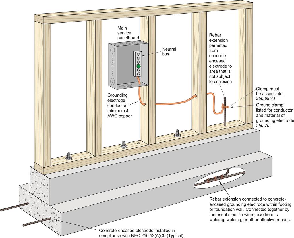
36 250.68(C)(3)

37 Service Raceways and Enclosures, Exception Metal components in a run of PVC conduit that are isolated from contact by a minimum cover of 18 in. are not required to be connected to the grounded system conductor, supply side bonding jumper, or grounding electrode conductor FIGURE 4-2 Grounding or bonding not required for isolated metal components, Exception.
38 Bonding for Communication Systems Communication system bonding is required to be connected in accordance with (A) or (B).
39 250.94(A) The Intersystem Bonding Termination Device (1 of 4) An intersystem bonding termination (IBT) for connecting intersystem bonding conductors is required to be provided external to enclosures at the service equipment or metering equipment enclosure and at the disconnecting means for any additional buildings or structures. If an IBT is used, it is required to comply with the following (next slides):
40 250.94(A) The Intersystem Bonding Termination Device (2 of 4) 1. Be accessible for connection and inspection 2. Consist of a set of terminals with the capacity for connection of not less than three intersystem bonding conductors 3. Not interfere with opening the enclosure for a service, building or structure disconnecting means, or metering equipment
41 250.94(A) The Intersystem Bonding Termination Device (3 of 4) 4. At the service equipment, be securely mounted and electrically connected to an enclosure for the service equipment, to the meter enclosure, or to an exposed nonflexible metallic service raceway, or be mounted at one of these enclosures and be connected to the enclosure or to the grounding electrode conductor with a minimum 6 AWG copper conductor
42 250.94(A) The Intersystem Bonding Termination Device (4 of 4) 5. At the disconnecting means for a building or structure, be securely mounted and electrically connected to the metallic enclosure for the building or structure disconnecting means, or be mounted at the disconnecting means and be connected to the metallic enclosure or to the grounding electrode conductor with a minimum 6 AWG copper conductor 6. The terminals shall be listed as grounding and bonding equipment (UL-467)


43 FIGURE 5-12 Intersystem bonding for communication systems,
44 250.94(A) Exception: Bonding for Existing Buildings or Structures (1 of 2) Exception: In existing buildings or structures, an accessible means external to enclosures for connecting intersystem bonding and grounding electrode conductors shall be permitted at the service equipment and at the disconnecting means for any additional buildings or structures by at least one of the following means
45 250.94(A) Exception: Bonding for Existing Buildings or Structures (2 of 2) 1. Exposed nonflexible metallic raceways 2. An exposed grounding electrode conductor 3. Approved means for the external connection of a copper or other corrosion-resistant bonding or grounding electrode conductor to the grounded raceway or equipment
46 250.94(B) Other Means (B) Other Means. Connections to an aluminum or copper busbar not less than ¼ in. thick 2 in. wide (6 mm thick 50 mm wide) and of sufficient length to accommodate at least three terminations for communication systems in addition to other connections. The busbar shall be securely fastened and shall be installed in an accessible location. Connections shall be made by a listed connector. If aluminum busbars are used, the installation shall also comply with (A). Exception to (A) and (B): Means for connecting intersystem bonding conductors are not required where communications systems are not likely to be used.

47 250.94(B) Other Means
48 (F) Conductors in Parallel For circuits of parallel conductors as permitted in (H), equipment grounding conductors are required to be installed in accordance with (1) or (2)
49 (F)(1)(a) Conductors in Parallel in Single Raceway or Cable Tray (a) Single Raceway or Cable Tray. If conductors are installed in parallel in the same raceway or cable tray, a single wire-type conductor shall be permitted as the equipment grounding conductor. The wire-type equipment grounding conductor shall be sized in accordance with , based on the overcurrent protective device for the feeder or branch circuit. Wire-type equipment grounding conductors installed in cable trays shall meet the minimum requirements of (B)(1)(c). Metal raceways or auxiliary gutters in accordance with or cable trays complying with (B) shall be permitted as the equipment grounding conductor.

50 (F)(1)(a) Conductors in Parallel (in single raceway) FIGURE 6-27 Sizing equipment grounding conductor for a circuit with parallel conductors in a single raceway, (F)(1)(a).
51 (F)(1)(b) Conductors in Parallel in Multiple Raceways (b) Multiple Raceways. If conductors are installed in parallel in multiple raceways, wiretype equipment grounding conductors, where used, shall be installed in parallel in each raceway. The equipment grounding conductor installed in each raceway shall be sized in compliance with based on the overcurrent protective device for the feeder or branch circuit. Metal raceways or auxiliary gutters in accordance with or cable trays complying with (B) shall be permitted as the equipment grounding conductor.

52 (F)(1)(b) Conductors in Parallel in Multiple Raceways FIGURE 6-28 Sizing equipment grounding conductor for a circuit with parallel conductors in multiple raceways, (F)(1)(b).
(2)(a).")
53 (F)(2)(a) Conductors in Parallel, Multiconductor Cables (a) If multiconductor cables are installed in parallel, the equipment grounding conductor(s) in each cable shall be connected in parallel. FIGURE 6-29 General requirement for connecting equipment grounding conductors for multiconductor cables that have circuit conductors that are connected in parallel (F)(2)(a).
54 (F)(2)(b) Conductors in Parallel, Multiconductor Cables (b) If multiconductor cables are installed in parallel in the same raceway, auxiliary gutter, or cable tray, a single equipment grounding conductor that is sized in accordance with shall be permitted in combination with the equipment grounding conductors provided within the multiconductor cables and shall all be connected together.

55 (F)(2)(b) Conductors in Parallel, Multiconductor Cables FIGURE 6-30 Provision for external equipment grounding conductor that supplements standard size equipment grounding conductor in multiconductor cables that are connected in parallel and installed in a raceway, auxiliary gutter, or cable tray (F)(2)(b).

56 (F)(2)(b) Conductors in Parallel, Multiconductor Cables Fault-current will be shared by all equipment grounding conductor paths in inverse proportion to the impedance of the individual path. FIGURE 6-31 Sizing equipment grounding conductor for four 200-ampere cables that have conductors connected in parallel (F)(2)(b).
(2)(b) for raceway or cable tray installations, the equipment grounding conductor in each multiconductor cable shall be sized in accordance with 250.")
57 (F)(2)(d) Equipment Grounding Conductor in Multiconductor Cables Except as provided in (F)(2)(b) for raceway or cable tray installations, the equipment grounding conductor in each multiconductor cable shall be sized in accordance with based on the overcurrent protective device for the feeder or branch circuit.

58 Cengage October 2017
59 Wiring Residential Series Written by Phil Simmons & Ray C. Mullin Includes Residential Construction Code Simulations Date


60 MindTap takes your electrical resources and delivers the content in a more engaging and meaningful way. Learners are challenged with assessment activities designed to teach them standards and code requirements. Simulations bring learners into a residential construction site where they need to determine code compliancy. Date mindtap 60

61 Date


 Quiz challenges Dynamic")
62 Delmar Online Training Simulation: Electricity and Wiring Includes electricity and residential wiring activities Interactive tutorials help you get started quickly Three main sections Basics of residential wiring Room-by-room wiring installations, Math Skills (includes induction and capacitance interactive equations) Quiz challenges Dynamic user feedback reports 62
NEC 2011 Code Changes
 NEC 2011 Code Changes Articles 280.21-300.50 CHANGES FROM 2008 TO 2011 CODE ARE IN RED Chapter 2 - Wiring and Protection ARTICLE 280 Surge Arresters, Over 1kV III. Connecting Surge Arresters 280.21 Connection
MECKLENBURG COUNTY. Land Use and Environmental Service Agency Code Enforcement 2/8/12 ELECTRICAL CONSISTENCY MEETING. Code Consistency Questions
 MECKLENBURG COUNTY Land Use and Environmental Service Agency Code Enforcement 2/8/12 ELECTRICAL CONSISTENCY MEETING Code Consistency Questions 1. I am inspecting a building addition. They have a 480V to
Fee $20 Course: NEC Changes 1 This course is valid for these credentials: Credential Description Cred Code Credit Hours
 www.garyklinka.com Page 1 of 18 Instructions: Fee $20 1. Print these pages. 2. Circle the correct answers and transfer them to the answer sheet. 3. Page down to the last page for the verification forms
CHAPTER V RESIDENTIAL WIRING
 CHAPTER V RESIDENTIAL WIRING 5.1. THE SERVICE ENTRANCE Buildings and other structures receive the electrical energy through the service entrance. In residential wiring, the electric company supply this
Spring Test 7 due 05/03/2013
 Spring Test 7 due 05/03/2013 Multiple Choice Identify the choice that best completes the statement or answers the question. 1. A raceway contains two 3-phase, 3-wire circuits that supply 38 ampere continuous
A Look at the 2017 NEC Significant Changes
 A Look at the 2017 NEC Significant Changes A Look at the 2017 NEC Significant Changes Michael J. Johnston NECA James T. Dollard Local 98 Philadelphia Electrical JATC This session is eligible for 1 Continuing
Continued from Part 2 Rules
 Continued from Part 2 Rules 26 50. 51 250.94 Grounding (Bonding) of Communications Systems An accessible bonding point must be provided at service equipment or the disconnecting means of separate buildings
Mecklenburg County Common Code Defects
 Electrical Code Defects Improper Over Current Protection Code Description 310.15 Ampacities for s Rated 0 2000 Volts. (A) General. (1) Tables or Engineering Supervision. Ampacities for conductors shall
Electrical Tech Note 111 Biosystems & Agricultural Engineering Department Michigan State University
 Electrical Tech Note 111 Biosystems & Agricultural Engineering Department Michigan State University Electrical Code Changes in Michigan 1 (Based on Part 8, P.A. 230, the 2005 NEC and the 2003 MRC) This
SUPPLEMENTAL CORRECTION SHEET FOR SOLAR PHOTOVOLTAIC SYSTEMS - ELECTRICAL
 SUPPLEMENTAL CORRECTION SHEET FOR SOLAR PHOTOVOLTAIC SYSTEMS - ELECTRICAL This is intended to provide uniform application of the codes by the plan check staff and to help the public apply the codes correctly.
SECTION 1: Field Inspection Guide for Rooftop Photovoltaic (PV) Systems
 Systems") COUNTY OF SANTA CRUZ PLANNING DEPARTMENT 701 OCEAN STREET, 4 th FLOOR, SANTA CRUZ, CA 95060 (831) 454-2580 FAX: (831) 454-2131 TDD: (831) 454-2123 KATHLEEN MOLLOY PREVISICH, PLANNING DIRECTOR Photovoltaic
COUNTY OF SANTA CRUZ PLANNING DEPARTMENT 701 OCEAN STREET, 4 th FLOOR, SANTA CRUZ, CA 95060 (831) 454-2580 FAX: (831) 454-2131 TDD: (831) 454-2123 KATHLEEN MOLLOY PREVISICH, PLANNING DIRECTOR Photovoltaic
NEC 2014 Code Changes
 NEC 2014 Code Changes Articles 310 310.120 CHANGES FROM 2011 TO 2014 CODE ARE IN RED ARTICLE 310 Conductors for General Wiring I. General 310.2 Definitions Electrical Ducts Electrical conduits, or other
This is intended to provide uniform application of the codes by the plan check staff and to help the public apply the codes correctly.
 SUPPLEMENTAL CORRECTION SHEET FOR SOLAR PHOTOVOLTAIC SYSTEMS (ELEC) This is intended to provide uniform application of the codes by the plan check staff and to help the public apply the codes correctly.
The following are specific provisions of 1910(a)(2) that could be seen in the LBM sector
(2) that could be seen in the LBM sector") Know the Rules on Temporary Wiring OSHA Standard 1910.305, Wiring methods, components, and equipment for general use, addresses wiring methods, components, and equipment for general use as one of several
Know the Rules on Temporary Wiring OSHA Standard 1910.305, Wiring methods, components, and equipment for general use, addresses wiring methods, components, and equipment for general use as one of several
Chapter 2 Wiring and Protection Article 200 Use and Identification of Grounded Neutral Conductor Chapter 1 General...9
 Article 90 Introduction...1 90.1 Purpose of the NEC...1 90.2 Scope of the NEC...2 90.3 Code Arrangement...4 90.4 Enforcement...5 90.5 Mandatory Requirements and Explanatory Material...6 90.6 Formal Interpretations...6
90.2 Scope. The installation of electrical conductors, equipment and raceways for:
 NEC Generator Primer Rules on the installation of generators and transfer switches 1 90.2 Scope The installation of electrical conductors, equipment and raceways for: public and private premises Conductors
2016 Photovoltaic Solar System Plan Review List
 Building Division 555 Santa Clara Street Vallejo CA 94590 707.648.4374 2016 Photovoltaic Solar System Plan Review List GENERAL PROJECT INFORMATION PLAN CHECK NO DATE JOB ADDRESS CITY ZIP REVIEWED BY PHONE
Electrical Tech Note 106
 Electrical Tech Note 106 Biosystems & Agricultural Engineering Department Michigan State University Master Exam Study Guide and Sample Questions 1 Based on the 2014 NEC, Part 8 of PA 230, PA 407, and the
Spring Test 10 due 05/11/2013
 Spring Test 10 due 05/11/2013 Multiple Choice Identify the letter of the choice that best completes the statement or answers the question. 1. When installed in an agricultural building that houses livestock
U-18. Company furnishes and installs: 10. Service lateral and connectors. 11. Conduit package, Amperes.
 SERVICE TERMINATION IN A TERMINATION COMPARTMENT DIRECT BURIED OR CONCRETE ENCASED LATERAL ALL 1-PHASE VOLTAGES, 400-800 AMPERES ALL 3-PHASE VOLTAGES, 400-3000 AMPERES ONLY Obtain acceptance for 1-phase
Definitions of and have been revised. a. automatic b. nonautomatic c. none of the above d. both a and b
 www.garyklinka.com Page 1 of 12 Instructions: Fee $25 1. Print these pages. 2. Circle the correct answers and transfer them to the answer sheet. 3. Page down to the last page for the verification forms
Western Section 101 st Annual Meeting Hot Springs, Arkansas September 21, 2005 Charlie Trout Code Breakfast
 Western Section 101 st Annual Meeting Hot Springs, Arkansas September 21, 2005 Charlie Trout Code Breakfast 1.Question: An add on unit for a hydromassage bathtub consists of a small 1-gallon water heater
Pretest Module 24 Three-phase Service Entrance
 Pretest Module 24 Three-phase Service Entrance 1. What is the most widely used three-phase service entrance system? 2. What are the three most common voltage combinations for three-phase, four-wire systems?
Photovoltaic Solar Plan Review
 PAIGE B. VAUGHAN, CBO Director of Building and Safety Phone (310) 605-5509 Fax Line (310) 605-5598 E-mail:lbutler@comptoncity.org Building & Safety Department Photovoltaic Solar Plan Review Plan Check
SECTION 300 OVERHEAD SERVICE
 SECTION 300 OVERHEAD SERVICE 300.01 General Company provides, installs, and maintains service drop to point of delivery approved by Company. Customer provides point of attachment which is acceptable to
UNDERGROUND SERVICES - SECONDARY
 UNDERGROUND SERVICES - SECONDARY Contents - Underground Services... U-1 General Requirements for Underground Service...U-2 Names of Parts for Underground Service... U-3 Service Termination in a Service
SOLAR PV STANDARD PLAN - COMPREHENSIVE Central/String Inverter Systems for One and Two Family Dwellings
 SCOPE: Use this plan ONLY for utility-interactive central/string inverter systems not exceeding a total combined system ac inverter output rating of 10kW on the roof of a one- or two-family dwelling or
9/16/2010. Chapter , The McGraw-Hill Companies, Inc. TRANSMISSION SYSTEMS. 2010, The McGraw-Hill Companies, Inc.
 Chapter 3 TRANSMISSION SYSTEMS 1 Transmitting large amounts of electric energy over long distances is accomplished most efficiently by using high-voltages. Without transformers the widespread distribution
Electrical Tech Note 105 Agricultural Engineering Department Michigan State University
 Electrical Tech Note 105 Agricultural Engineering Department Michigan State University Journey Exam Study Guide and Sample Questions 1 Based on the 2002 NEC, Part 8 of PA 230, and the 2003 MRC The Journey
See Part 3 for the Introduction for Article 314
 See Part 3 for the Introduction for Article 314 76 314.25 Covers and Canopies When the installation is complete, each outlet box must be provided with a cover or faceplate, unless covered by a fixture
Western Section IAEI Code Panel Questions
 Western Section IAEI 2013 Code Panel Questions 1. Do the factory wings that many fluorescent troffers have designed to fold out over the grid meet the requirements for securely fastened to the framing?
ARKANSAS ELECTRICIANS
 CONTINUING EDUCATION FOR ARKANSAS ELECTRICIANS 2014 NEC Code Change 8 Hours AMERICAN ELECTRICAL INSTITUTE N16 W23217 Stone Ridge Drive, Suite 290 Waukesha, WI 53188 855-780-5046 www.aeitraining.com DISCLAIMER
Section 02: Pre-Installation Procedures
 Section 02: Pre-Installation Procedures Foundation! WARNING The MUST be placed on a surface that will support the combined weight of the, options, fixtures, and tooling, etc. (refer to the Specifications
Data Bulletin. Wire Temperature Ratings and Terminations INTRODUCTION WHY ARE TEMPERATURE RATINGS IMPORTANT?
 Data Bulletin March 2002 Lexington, KY, USA Wire Temperature Ratings and Terminations INTRODUCTION WHY ARE TEMPERATURE RATINGS IMPORTANT? Table 1: Insulation Type Figure 1: Figure 2: Ampacity of a 1/0
2011 NEC Code Updates Part 3
 www.garyklinka.com Page 1 of 22 Instructions: Fee $35 1. Print these pages. 2. Circle the correct answers and transfer them to the answer sheet. 3. Page down to the last page for the verification forms
SINGLE PHASE WIRING SPECIFICATIONS
 SINGLE PHASE WIRING SPECIFICATIONS 1-866-MEC-ELEC (1-866-632-3532) Office Locations: Hondo Office 237 Hwy 173 N Hondo, TX 78661-0370 Fax 830.426.3335 Dilley Office 1718 W. FM 117 Dilley, TX 78017 Fax 830.965.1425
THREE PHASE WIRING SPECIFICATIONS
 THREE PHASE WIRING SPECIFICATIONS 1-866-MEC-ELEC (1-866-632-3532) Office Locations: Hondo Office 237 Hwy 173 N Hondo, TX 78661-0370 Fax 830.426.3335 Dilley Office 1718 W. FM 117 Dilley, TX 78017 Fax 830.965.1425
Section 6 Electric Metering: Residential
 Section 6 Electric Metering: Residential 6.1. Scope This section provides specific information for residential metering that is not covered by the basic requirements in Section 5, Electric Metering: General.
Installing a Downstream Distribution Panelboard
 Job Sheet 5 Installing a Downstream Distribution Panelboard OBJECTIVE To install a downstream distribution panelboard (DDP) on the Mobile Workstation. To mechanically and electrically connect the DDP to
MECKLENBURG COUNTY. Land Use and Environmental Service Agency Code Enforcement 9/14/11 ELECTRICAL CONSISTENCY MEETING. Code Consistency Questions
 MECKLENBURG COUNTY Land Use and Environmental Service Agency Code Enforcement 9/14/11 ELECTRICAL CONSISTENCY MEETING Code Consistency Questions 1. I recently installed a 45-KVA transformer, 480-volt primary
The Reliable Choice. Field Pocket Guide
 The Reliable Choice Field Pocket Guide Allowable Ampacities of STABILOY Brand XHHW-2 and Copper 75 C (167 F) 90 C (194 F) 75 C (167 F) 90 C (194 F) Conductor Size (AWG or kcmil) Types RHW, THHW, THW, THWN,
Western Section IAEI Code Panel Questions
 Western Section IAEI 2013 Code Panel Questions 1. Do the factory wings that many fluorescent troffers have designed to fold out over the grid meet the requirements for securely fastened to the framing?
TRANSMISSION SYSTEMS
 TRANSMISSION SYSTEMS Transmitting large amounts of electric energy over long distances is accomplished most efficiently by using high-voltages. Without transformers the widespread distribution of electric
Understanding National Electric Code (NEC) tap rules How do they apply to circuit breaker terminals?
 tap rules How do they apply to circuit breaker terminals?") White paper Understanding National Electric Code (NEC) tap rules How do they apply to circuit breaker terminals? Darryl Moser, Business Development Manager, DEM Sales, ABB, Electrification Products Division
White paper Understanding National Electric Code (NEC) tap rules How do they apply to circuit breaker terminals? Darryl Moser, Business Development Manager, DEM Sales, ABB, Electrification Products Division
CHAPTER 10 ELECTRICAL. Notes:
 CHAPTER 10 ELECTRICAL 1001.0 General Requirements. Electrical wiring and equipment shall comply with the requirements of NFPA 70, National Electrical Code (NEC), or local ordinances. 1002.0 Solar Photovoltaic
AGRICULTURAL UNDERGROUND SERVICE 500 HP OR LESS
 Prepared by: ABB1 AGRICULTURAL UNDERGROUND SERVICE 500 HP OR LESS 05619 Asset Type: Electric Metering Function: Design and Construction Issued by: Lisseth Villareal (LDV2) Date: 07-31-15 Rev. #10: This
The 84 th NC Electrical Institute Code Questions April 9 th & 10 th 2013 North Raleigh Hilton Raleigh, NC
 The 84 th NC Electrical Institute Code Questions April 9 th & 10 th 2013 North Raleigh Hilton Raleigh, NC www.ncdoi.com www.ncbeec.org NC DEPARTMENT OF INSURANCE NC STATE BOARD OF EXAMINERS OF ELECTRICAL
ELECTRIC SERVICE RULES DISTRIBUTED GENERATION Issued Jan 2016
 DISTRIBUTED GENERATION CHAPTER 5 500. SCOPE This chapter includes distributed or customer-owned generation connected in parallel and operating with Alliant Energy s electric distribution system. For all
ROCKY MOUNTAIN CHAPTER IAEI MARCH 15-16, 2012
 ROCKY MOUNTAIN CHAPTER IAEI MARCH 15-16, 2012 1) Can a switched outlet be on a small appliance branch circuit for dining room lighting? No, a switched outlet on a general purpose branch circuit may be
AMENDMENT ELECTRIC SERVICE MANUAL 2014
 AMENDMENT (Pages 20,43,50,72,74,,76,78,83,86,99) ELECTRIC SERVICE MANUAL 2014 Effective April 1, 2015 18-7 6.0 SERVICE AND SERVICE ENTRANCES (General), Continued Conductor Sizing It is recommended that
SECTION PANELBOARDS
 SECTION 16470 PANELBOARDS PART 1 - GENERAL 1.1 RELATED DOCUMENTS A. The general provisions of the contract including General and Special Conditions and General Requirements shall apply to all work under
grounded in service wired to innovate STABILOY Type XHHW-2 and USE-2/RHH/RHW-2
 grounded in service wired to innovate STABILOY Type XHHW-2 and USE-2/RHH/RHW-2 grounded in service wired to innovate www.cable.alcan.com Type XHHW-2 and Type USE-2/RHH/RHW-2 Alcan manufactures XHHW-2 and
COMMERCIAL QUICK REFERENCE
 COMMERCIAL QUICK REFERENCE PROVO CITY POWER STANDARDS ELECTRICAL ENGINEERING UPDATED: 2016 SPECIFICATIONS SUBJECT TO CHANGE WITHOUT NOTIFICATION. 18" MIN. OF TAIL. (NEUTRAL CONDUCTOR MUST BE WHITE OR
TEMPORARY ELECTRIC WIRING FOR CARNIVALS, CONVENTIONS, EXHIBITIONS, FAIRS AND SIMILAR USES
 INFORMATION BULLETIN / PUBLIC - ELECTRICAL CODE REFERENCE NO.: LAMC 93.0230 Effective: 3-24-69 DOCUMENT NO. P/EC 2002-006 Revised: 11-17-00 Previously Issued As: RGA #7-69 TEMPORARY ELECTRIC WIRING FOR
10 Commercial, Industrial, Agricultural Services
 10 Commercial, Industrial, Agricultural Services This section describes the Power Company requirements for commercial, industrial, and agricultural services. This section covers single phase and three
Pentahead bolts See note 2. Conduit run as specified. Company facility. Refer to drawing SS8.6-2 or SS8.6-3 STANDARD SERVICE INSTALLATION
 PULL BOX F SECONDARY SYSTEM Typical grade Pentahead bolts See note 2 Conduit run as specified Plastic or fiberglass for grass areas or Polymer concrete for light duty areas (see notes 2, 3, & 4) Company
2011/2008/2005 NATIONAL ELECTRICAL CODE SOLAR PV CODE COMPLIANCE REFERENCE
 2011/2008/2005 NATIONAL ELECTRICAL CODE SOLAR PV CODE COMPLIANCE REFERENCE PAGE 1 OF 5 This Reference provides a very comprehensive list of aspects of a solar PV installation that could be reviewed, clarifying
Generator Fire Safety: Generator assemblies should be located outside the building.
 SECTION 33 70 00 - ELECTRICAL DISTRIBUTION PACKAGED GENERATOR ASSEMBLIES Generator Fire Safety: Generator assemblies should be located outside the building. All fuel piping from the outside of the building
(The actual state exam will be closer to 50 questions in 4 hours time) Master Electrician Practice Test
 Master Electrician Practice Test") (The actual state exam will be closer to 50 questions in 4 hours time) Master Electrician Practice Test 1. Accessible as applied to wiring methods means capable of being removed or exposed without damaging
(The actual state exam will be closer to 50 questions in 4 hours time) Master Electrician Practice Test 1. Accessible as applied to wiring methods means capable of being removed or exposed without damaging
9/7/2010. Objectives. Article 90. Introduction NEC Significant Changes. Review significant revisions in the 2011 NEC
 2011 NEC Significant Changes Courtesy of NJATC Courtesy of NFPA Presented By: Michael J. Johnston Executive Director of Standards and Safety, NECA Objectives Review significant revisions in the 2011 NEC
PART A General Conductor Requirements
 PART A General Conductor Requirements 6.1 Conductor Insulation Property Table 310.13 of the NEC provides information on conductor properties such as permitted use, maximum operating temperature, and other
Temporarily Approved Solar Photovoltaic System Electrical Schematics
 March 20, 2019 Page 1 of 10 Temporarily Approved Solar Photovoltaic System Electrical Schematics This document is intended as a temporary interpretation of approved solar photovoltaic electrical schematics
Chapter 8 Interior Wiring and Lighting
 Chapter 8 Interior Wiring and Lighting Review Questions 1. What tool if any, is used to remove a fuse that is to be replaced? 1. Pliers 2. Screwdriver 3. Fuse puller 4. None 2. OSHA has established specific
Fee $100 Course: NEC Proposed Changes Part 1 This course is valid for these credentials: Credential Description Cred Code Credit Hours
 www.garyklinka.com Page 1 of 31 Instructions: Fee $100 1. Print these pages. 2. Circle the correct answers and transfer them to the answer sheet. 3. Page down to the last page for the verification forms
GET GROUNDED. Renewable Energy System Grounding Basics
 GET GROUNDED Renewable Energy System ing Basics by Christopher Freitas ASK TEN RENEWABLE ENERGY INSTALLERS ABOUT SYSTEM GROUNDING and you ll likely get ten different opinions as to what the National Electrical
Solar PV Standard Electrical Plan
 *** Provide this document to the inspector along with ALL system installation instructions *** Project Address: Permit Number: SCOPE: Standard plan for installation of solar PV systems utilizing 2 wire
Table of Contents. Unit 3 Magnetism Unit 1 Matter Unit 4 Electricity Unit 2 Electron Theory Unit 5 Electromagnetism...
 Introduction...x How to Use This Textbook...xi About the Author...xii About the Graphic Illustrator...xiii Mike Holt Enterprises Team...xiv Chapter 1 Electrical Fundamentals... 1 Unit 1 Matter... 3 Introduction...
Corrections most seen on plan review October 18, 2017 David Rankin Seattle Department of Construction and Inspections
 Corrections most seen on plan review October 18, 2017 David Rankin Seattle Department of Construction and Inspections One-Line / Riser Diagrams Drawings are not reviewed prior to submission. Because of
NEC Code-Making Panel 5. Second Draft Meeting Agenda. November 9-14, San Diego, CA Introduction of Members and Guests
 National Fire Protection Association 1 Batterymarch Park, Quincy, MA 02169-7471 Phone: 617-770-3000 Fax: 617-770-0700 www.nfpa.org NEC Code-Making Panel 5 Second Draft Meeting Agenda November 9-14, 2015
Overcurrent Protection (2014 NEC) (Homestudy)
 (Homestudy)") Overcurrent Protection (2014 NEC) (Homestudy) Oregon Electrical License The key sections of Article 240 will be discussed. Overcurrent protection for panelboards, appliances, motors, motor compressors,
Overcurrent Protection (2014 NEC) (Homestudy) Oregon Electrical License The key sections of Article 240 will be discussed. Overcurrent protection for panelboards, appliances, motors, motor compressors,
CHAPTER 10 ELECTRICAL
 1001.0 General Requirements. 1001.1 Electrical Wiring and Equipment. Electrical wiring and equipment shall comply with the requirements of NFPA 70, National Electrical Code (NEC), or local ordinances.
SERVICE ATTACHMENT ON A BUILDING WITH BUS DUCT SERVICE ENTRANCE AND INDOOR METERING
 SERVICE ATTACHMENT ON A BUILDING WITH BUS DUCT SERVICE ENTRANCE AND INDOOR METERING Obtain acceptance and specific details from the local Company office. 1. Service entrance duct (see Note 1). Company
Microinverters and AC PV modules are becoming. Microinverters and AC PV Modules. Different Beasts. Perspectives on PV.
 Perspectives on PV Microinverters and AC PV Modules Are Different Beasts by John Wiles Microinverters and AC PV modules are becoming very common in residential and small commercial PV systems. See photos
9. Non-Residential Services (Commercial, Industrial, and Agricultural)
") Section 9 2016 Electric Service Requirements, 3rd Edition Section 9 Non-Residential Services Directory Page 9.1 General Requirements 68 9.2 Direct-Connect Metering, Single Installations 69 9.3 Direct-Connect
Section 9 2016 Electric Service Requirements, 3rd Edition Section 9 Non-Residential Services Directory Page 9.1 General Requirements 68 9.2 Direct-Connect Metering, Single Installations 69 9.3 Direct-Connect
INSPECTION REQUIREMENTS: PHOTOVOLTAIC (PV) RESIDENTIAL
 RESIDENTIAL") Photovoltaic (PV) Residential Page 1 of 10 Revision Date: 07/18/2018 INSPECTION REQUIREMENTS: PHOTOVOLTAIC (PV) RESIDENTIAL INSPECTION CODE: 703 SCOPE: RESIDENTIAL APPLICABLE CODES: 2016 CBC, CRC, CPC,
Photovoltaic (PV) Residential Page 1 of 10 Revision Date: 07/18/2018 INSPECTION REQUIREMENTS: PHOTOVOLTAIC (PV) RESIDENTIAL INSPECTION CODE: 703 SCOPE: RESIDENTIAL APPLICABLE CODES: 2016 CBC, CRC, CPC,
Indianapolis Power & Light Company
 Indianapolis Power & Light Company Electric Service and Meter Manual The Electric Service & Meter Manual is not copyrighted and permission is hereby given to reproduce this document. However, the Indianapolis
SOME REVIEW - QUESTIONS 2011 NATIONAL ELECTRICAL CODE
 SOME REVIEW - QUESTIONS 2011 NATIONAL ELECTRICAL CODE J & W Educational Services 1340 Hickory Hill Dr. Watkinsville, Ga 30677 Jim Allison (706) 769-7112 jandw@uga.edu http://www.ugaed.com What is the Code
Customer Requirements Meter Socket Configurations
 Application Information on meter socket configurations available from Tacoma Power. For enclosed meter pedestals, see standard C-MR-0020 Customer Requirements, Enclosed Meter Pedestal. General Requirements
ELECTRIC VEHICLE CHARGING FOR BUILDINGS
 PLANNING & DEVELOPMENT SERVICES Office of the Chief Building Official BULLETIN 2015-004-BU/EL June 25, 2015 ELECTRIC VEHICLE CHARGING FOR BUILDINGS This bulletin provides clarification of requirements
Overcurrent Protection According to the 2011 NEC
 Overcurrent Protection According to the 2011 NEC Utah Electrical License This course will cover overcurrent protection according to the 2011 NEC. The key sections of Article 240 will be discussed. Overcurrent
2014 NEC Changes (Homestudy)
") 2014 NEC Changes (Homestudy) Idaho Electrical License This course will review the most important National Electrical Code changes from the 2014 NEC. Changes in Articles 100 - Chapter 9 will be covered.
2014 NEC Changes (Homestudy) Idaho Electrical License This course will review the most important National Electrical Code changes from the 2014 NEC. Changes in Articles 100 - Chapter 9 will be covered.
Bulletin Wiring methods for Solar Photovoltaic Systems Rule and , Tables 11 and 19
 -4-0 Bulletin -4-0 Wiring methods for Solar Photovoltaic Systems Rule -018 and -020, Tables 11 and 19 Scope Issued May 2012 (1) Introduction (2) New cable types RPV & RPVU (3) Wiring methods within photovoltaic
SURFACE TRACK (120/250V) SPECIFICATIONS
 SPECIFICATIONS") SURFACE TRACK (120/250V) SPECIFICATIONS GENERAL Lighting Track shall allow fixtures to be located anywhere along the track length. Fixtures shall be easily focused, switched, dimmed, accessorized and removed
SURFACE TRACK (120/250V) SPECIFICATIONS GENERAL Lighting Track shall allow fixtures to be located anywhere along the track length. Fixtures shall be easily focused, switched, dimmed, accessorized and removed
2000 Cooper Bussmann, Inc. Page 1 of 9 10/04/00
 DO YOU KNOW THE FACTS ABOUT SINGLE-POLE INTERRUPTING RATINGS? YOU MAY BE IN TROUBLE! Typical plant electrical systems use three-phase distribution schemes. As an industry practice, short-circuit calculations
2011 NEC Changes Part 2 (Homestudy) (Homestudy)
 (Homestudy)") 2011 NEC Changes Part 2 (Homestudy) (Homestudy) North Carolina Electrical License This course will review the second half of the most important National Electrical Code changes from the 2011 NEC. Changes
2011 NEC Changes Part 2 (Homestudy) (Homestudy) North Carolina Electrical License This course will review the second half of the most important National Electrical Code changes from the 2011 NEC. Changes
WIRING DESIGN & PROTECTION REQUIREMENTS CHECKLIST
 WIRING DESIGN & PROTECTION REQUIREMENTS CHECKLIST Use & Identification of Grounded and Grounding Conductors YES NO N/A Grounded conductors are identifiable and distinguishable from all other conductors.
4 018 (See App B) m Revised wording and clarification of requirements when selecting conductors
 m Revised wording and clarification of requirements when selecting conductors") 2012 Canadian Electrical Code Changes (CSA Errata not included) M = minor / S = significant / D = deleted N.m (Newton.metre) m New unit of torque Definitions cablebus m newly recognized wiring method ground
2012 Canadian Electrical Code Changes (CSA Errata not included) M = minor / S = significant / D = deleted N.m (Newton.metre) m New unit of torque Definitions cablebus m newly recognized wiring method ground
Preface...x Chapter 1 Electrical Fundamentals
 Preface...x Chapter 1 Electrical Fundamentals Unit 1 Matter...3 Introduction...3 1.1 Matter...3 1.2 Atomic Theory...3 1.3 Law of Electrical Charges...4 1.4 Law of Atomic Charges...5 Negative Atomic Charge...5
ECET Circuit Design Motor Loads. Branch Circuits. Article 210
 ECET 4520 Industrial Distribution Systems, Illumination, and the NEC Circuit Design Motor Loads Branch Circuits Article 210 210.1 Scope This article covers branch circuits except for those that supply
PHOTOVOLTAIC ELECTRICAL POWER SYSTEMS INSPECTOR/INSTALLER CHECKLIST
 PHOTOVOLTAIC ELECTRICAL POWER SYSTEMS INSPECTOR/INSTALLER CHECKLIST The following checklist is an outline of the general requirements found in the 2005 National Electrical Code (NEC) Article 690 for Photovoltaic
Volume 2 Charts, Formulas, and Other Useful Information
 Volume 2 Charts, Formulas, and Other Useful Information Aluminum Conductor Conductor Terminations 61 Compact Aluminum (Conduit Fill Tables) 68-79 Ampacity Dwelling Services 48 1-phase Loads on a 3-phase
Corflex. Continuous Corrugated Aluminum Sheathed PL, MC and MV Industrial Cables. Introduction Applications... 3
 Corflex Continuous Corrugated Aluminum Sheathed PL, MC and MV Industrial Cables Introduction................................. 2 Applications................................. 3 Corflex PL 300V Instrumentation
TABLE OF CONTENTS CHAPTER 1 ELECTRICAL THEORY About This Textbook...xi. Passing Your Exam...xiv. How to Use the National Electrical Code...
 TABLE OF CONTENTS About This Textbook...xi Passing Your Exam...xiv How to Use the National Electrical Code... 1 CHAPTER 1 ELECTRICAL THEORY... 7 Unit 1 Electrician s Math and Basic Electrical Formulas...
NEC REQUIREMENTS FOR GENERATORS
 PROFESSIONAL DEVELOPMENT SEMINAR SERIES NEC REQUIREMENTS FOR GENERATORS (Based on NEC 2005 with limited 2008 commentary) AIA certified Continuing Education Units (CEU) Available GPS-140 National Electric
SECTION ENCLOSED SWITCHES AND CIRCUIT BREAKERS
 PART 1 - GENERAL 1.1 DESCRIPTION SECTION 26 29 21 ENCLOSED SWITCHES AND CIRCUIT BREAKERS SPEC WRITE NOTE: Delete between // // if not applicable to project. Also delete any other item or paragraph not
INSTALL SERVICE- ENTRANCE SYSTEMS
 SUBCOURSE EN5141 EDITION B US ARMY ENGINEER SCHOOL INSTALL SERVICE- ENTRANCE SYSTEMS INSTALL SERVICE- ENTRANCE SYSTEMS Subcourse Number EN5141 EDITION B United States Army Engineer School Fort Leonard
2014 NEC Update RV
 PLEASE DO NOT BOOKMARK ANY ANYTIMECE WEBPAGES! Our system will remember the last page you viewed when logging out and back in but please DO NOT exit out when taking a test. Your place will NOT be saved.
FOR ALL STAKEHOLDERS TO
 Our Goal is FOR ALL STAKEHOLDERS TO HAVE A SUCCESSFUL PROJECT with us and that together we keep people and structures safe and buildings economically viable to serve the needs of our community. We strive
Sentinel Field Satellite Controller Metal Pedestal, Plastic Pedestal and Wall Mount Models Installation Instructions
 WARNING HIGH VOLTAGE 115V 4 M AP Sentinel Field Satellite Controller Metal Pedestal, Plastic Pedestal and Wall Mount Models Installation Instructions Important: For your protection and the safety of the
2014 NEC Changes Part 4
 www.garyklinka.com Page 1 of 14 Instructions: Fee $25 1. Print these pages. 2. Circle the correct answers and transfer them to the answer sheet. 3. Page down to the last page for the verification forms