MX Series. Slide Tables MXH, MXS, MXQ, MXF, MXW, MXP
|
|
|
- Roland Hopkins
- 5 years ago
- Views:
Transcription

1 CT. N37 Slide Tables MX Series MXH, MXS, MXQ, MXF, MXW, MXP PRODUCTS Integrated Cylinder and Guide Bearing Styles Multiple Mounting and Porting Configurations Bore Sizes from ømm to ømm Wide Range of Options
2
3 Table of Contents MX Series Features...pages - Safety Instructions... pages - MXH...pages 9-11 MXS...pages 1-1 MXQ...pages 1-17 MXF...page 18 MXW...page 19 MXP...pages -1 MXH Series...pages 3-39 MXS Series...pages -7 MXQ Series...pages MXF Series...pages MXW Series...pages13-1 MXP Series...pages uto Switches...pages uto Switch Precautions...pages PRODUCTS Targeting new trends in the advancement of industrial automation, SMC has developed a category of products recognized as especially significant and of universal importance. We refer to these products as Z Products. These revolutionary products, whether simple or complex, provide SMC customers with superior performance and availability at a very affordable cost. The Preferred Option Program: Quick Delivery and Service ssurance Options highlighted in blue: Preferred Option Program The product series in this catalog utilize SMC s Preferred Option Program, a unique program intended to emphasize the model configurations that are most readily available where the catalog presents an extensive variety of choice. ll other options are available, whereas they may be stocked in lesser quantities or manufactured to order. Special arrangements can be made for repeating (blanket) orders of these product models. Contact your sales representative for further details. 3

4 MX Series MXH, MXS, MXQ, MXF, MXW, MXP Unmatched Versatility From The Leader In Pneumatic Slide Table Technology. Conventional System Linear Guide Work Table Cylinder Pneumatic Slide Table Table Linear Bearing Pneumatic Cylinder Base Plate SMC has pioneered the development of compact integration of pneumatic cylinders and guided slide tables. The result is the widest range of pneumatically actuated slide tables in the industry, the MX family. The MX slides are available in six styles to meet a variety of application needs. MXH Universal Mount Slide Table Multiple Mounting Options MXS Slide Table Good Precision nd Many Options MXQ Precision Slide Table Better Precision nd More Options MXF Low Profile Slide Table Suitable For pplications With Limited Space MXW Long Stoke Slide Table Ideal For Transfer nd Pressing pplications MXP Compact Slide Table Extreme Precision
5 Versatile Sizes Bore sizes and stroke lengths to provide the movement you need. Bore Size (mm) Standard Stroke (mm) Dual Rods For Twice The Force MXH MXS MXQ MXF MXW MXP The MXS, MXQ, and MXW use a twin bore design to double the actuation force while maintaining the single bore height. Versatile Performance Precision and strength in configurations to meet most applications. Best Precision vs. Moment Loading Precision MXH MXF MXP MXQ MXW MXS Two Bearing Styles For Different Performance Needs Cross Roller Linear Guide (MXF, MXS) Recirculating Linear Guide (MXH, MXQ, MXW, MXP) Good Moment Loading Best Versatile Options wide array of standard and optional features. Porting MXF, MXW, MXP: Standard Locations MXH: 3 Standard Locations MXS, MXQ: Standard Lateral Locations, Optional xial Porting Stroke djustment MXF, MXW, MXP: Standard MXS, MXQ: Optional MXW, MXS, MXQ: Optional Shock bsorber/stroke djustment MXQ: Optional Hard (non-cushioned) adjusters Functional Options Buffer: MXS, MXQ End Lock: MXS, MXQ Mounting ll Models Feature Both Through Hole nd Tapped Body Mounting
6 MX Series Safety Instructions Slide Tables These safety instructions are intended to prevent a hazardous situation and/or equipment damage. These instructions indicate the level of potential hazard by a label of "Caution", "Warning" or "Danger". To ensure safety, be sure to observe ISO 1 Note 1), JIS B 837 Note ) and other safety practices. Caution : Operator error could result in injury or equipment damage. Warning : Operator error could result in serious injury or loss of life. Danger : In extreme conditions, there is a possible result of serious injury or loss of life. Note 1) ISO 1 : Pneumatic fluid power -- Recommendations for the application of equipment to transmission and control systems. Note ) JIS B 837 : Pneumatic system axiom. Warning 1. The compatibility of pneumatic equipment is the responsibility of the person who designs the pneumatic system or decides its specifications. Since the products specified here are used in various operating conditions, their compatibility for the specific pneumatic system must be based on specifications or after analysis and/or tests to meet your specific requirements.. Only trained personnel should operate pneumatically operated machinery and equipment. Compressed air can be dangerous if an operator is unfamiliar with it. ssembly, handling or repair of pneumatic systems should be performed by trained and experienced operators. 3. Do not service machinery/equipment or attempt to remove components until safety is confirmed. 1. Inspection and maintenance of machinery/equipment should only be performed after confirmation of safe locked-out control positions.. When equipment is to be removed, confirm the safety process as mentioned above. Cut the supply pressure for this equipment and exhaust all residual compressed air in the system. 3. Before machinery/equipment is restarted, take measures to prevent shooting-out of cylinder piston rod, etc. (Bleed air into the system gradually to create back-pressure.). Contact SMC if the product is to be used in any of the following conditions: 1. Conditions and environments beyond the given specifications, or if product is used outdoors.. Installation on equipment in conjunction with atomic energy, railway, air navigation, vehicles, medical equipment, food and beverages, recreation equipment, emergency stop circuits, press applications, or safety equipment. 3. n application which has the possibility of having negative effects on people, property, or animals, requiring special safety analysis.
7 Slide Tables Warning Precautions on design 1. There is a possibility of dangerous sudden action by air cylinders if sliding parts of machinery are twisted due to external forces, etc. In such cases, human injury may occur; e.g., by catching hands or feet in the machinery, or damage to the machinery itself may occur. Therefore, the machine should be designed to avoid such dangers.. protective cover is recommended to minimize the risk of personal injury. If a stationary object and moving parts of a cylinder are in close proximity, personal injury may occur. Design the structure to avoid contact with the human body. 3. Securely tighten all stationary parts and connected parts so that they will not become loose. When a cylinder operates with high frequency or a cylinder is installed where there is a lot of vibration, ensure that all parts remain secure.. deceleration circuit or shock absorber, etc., may be required. When a driven object is operated at high speed or the load is heavy, a cylinder s cushion will not be sufficient to absorb the shock. Install a deceleration circuit to reduce the speed before cushioning, or install an external shock absorber to relieve the shock. In this case, the rigidity of the machinery should also be examined.. Consider a possible drop in operating pressure due to a power outage, etc. When a cylinder is used in a clamping mechanism, there is a danger of work dropping if there is a decrease in clamping force due to a drop in circuit pressure caused by a power outage, etc. Therefore, safety equipment should be installed to prevent damage to machinery and human injury. Suspension mechanisms and lifting devices also require consideration for drop prevention.. Consider a possible loss of power source. Measures should be taken to protect against human injury and equipment damage in the event that there is a loss of power to equipment controlled by air pressure, electricity or hydraulics, etc. 7. Design circuitry to prevent sudden lurching of driven objects. When a cylinder is driven by an exhaust center type directional control valve or when starting up after residual pressure is exhausted from the circuit, etc., the piston and its driven object will lurch at high speed if pressure is applied to one side of the cylinder because of the absence of air pressure inside the cylinder. Therefore, equipment should be selected and circuits designed to prevent sudden lurching, because there is a danger of human injury and/or damage to equipment when this occurs. 8. Consider emergency stops. Design so that human injury and/or damage to machinery and equipment will not be caused when machinery is stopped by a safety device under abnormal conditions, a power outage or a manual emergency stop. 9. Consider the action when operation is restarted after an emergency stop or abnormal stop. Design the machinery so that human injury or equipment damage will not occur upon restart of operation. When the cylinder has to be reset at the starting position, install manual safety equipment. Warning Selection MX Series ctuator Precautions 1 1. Check the specifications. The products advertised in this catalog are designed for use in industrial compressed air systems. If the products are used in conditions where pressure, temperature, etc., are out of specification, damage and/or malfunction may be caused. Do not use in these conditions. Consult SMC if you use a fluid other than compressed air.. Intermediate stops. When intermediate stopping of a cylinder piston is performed with a 3 position closed center type directional control valve, it is difficult to achieve stopping positions as accurate and minute as with hydraulic pressure, due to the compressibility of air. Furthermore, since valves and cylinders, etc. are not guaranteed for zero air leakage, it may not be possible to hold a stopped position for an extended period of time. Contact SMC in case it is necessary to hold a stopped position for an extended period. Caution 1. Operate the piston within a range such that collision damage will not occur at the end of the stroke. Operate within a range such that damage will not occur when the piston having inertial force stops by striking the cover at the stroke end. Refer to the cylinder type selection procedure for the range within which damage will not occur.. Use a speed controller to adjust the cylinder drive speed, gradually increasing from a low speed to the desired speed setting. 7
8 MX Series ctuator Precautions Caution 1. Be certain to align the rod shaft center with the load and direction of movement when connecting. When not properly aligned, problems may arise with the rod and tubing, and damage may be caused due to friction on areas such as the inner surface of the tubing, bushings, rod surface and seals.. Do not scratch or dent the sliding parts of the cylinder tube or piston rod, etc., by striking or grasping them with other objects. Cylinder bores are manufactured to precise tolerances, so that even a slight deformation may cause faulty operation. Moreover, scratches or dents, etc. in the piston rod may lead to damaged seals and cause air leakage. 3. Do not use until you verify that the equipment can operate properly. fter mounting, repair or modification, etc., connect the air supply and electric power, and then confirm proper mounting by means of appropriate function and leak inspections.. Instruction manual. The product should be mounted and operated after thoroughly reading the manual and understanding its contents. Keep the instruction manual where it can be referred to as needed. Caution Mounting Piping 1. Preparation before piping. Before piping is connected, it should be thoroughly blown out with air (flushing) or washed to remove cutting chips, cutting oil and other debris from inside the pipe.. Wrapping of pipe tape. When screwing together pipes and fittings, etc., be certain that cutting chips from the pipe threads and sealing material do not get inside the piping. lso, when pipe tape is used, leave 1. to thread ridges exposed at the end. Wrapping direction Expose approx. threads Caution Pipe tape Lubrication 1. Lubrication of non-lube type cylinder. The cylinder is lubricated at the factory and can be used without any further lubrication. However, in the event that it will be lubricated, use class 1 turbine oil (with no additives) ISO VG3. Stopping lubrication later may lead to malfunction due to the loss of the original lubricant. Therefore, lubrication must be continued once it has been started. Warning ir Supply Slide Tables 1. Use clean air. If compressed air includes chemicals, synthetic oils containing organic solvents, salt or corrosive gases, etc., it can cause damage or malfunction. Caution 1. Install air filters. Install air filters at the upstream side of valves. The filtration degree should be µm or finer.. Install an air dryer, after cooler, etc. ir that includes much condensate causes malfunction of valves and other pneumatic equipment. To prevent this, install an air dryer or after cooler, etc. 3. Use the product within the specified range of fluid and ambient temperature. Take measures to prevent freezing, since moisture in circuits will be frozen under - C, and this may cause damage to seals and lead to malfunction. Refer to the ir Cleaning Equipment catalog for details on compressed air quality. Warning Operating Environment 1. Do not use in environments where there is a danger of corrosion. Refer to the construction drawings regarding cylinder materials.. In dirty areas, such as dusty locations or where water, oil, etc. splash on the equipment, take suitable measures to protect the Warning Maintenance 1. Maintenance should be done according to the procedure indicated in the instruction manual. If handled improperly, malfunction and damage of machinery or equipment may occur.. Machine maintenance, and supply and exhaust of compressed air. When machinery is serviced, first confirm measures to prevent dropping of driven objects and run-away of equipment, etc. Then cut off the supply pressure and electric power, and exhaust all compressed air from the system. When machinery is restarted, confirm that operation is normal with actuators in the proper positions. Caution 1. Drain flushing. Remove condensate from air filters regularly. (Refer to specifications.) 8

9 Compact Slide MXH Series Specific Product Precautions 1 uto Switch Mounting Precautions When installing in close proximity Caution (1) In compact slides with D-9 or D-F9 type auto switches, there is a danger of auto switch malfunction if the mounting pitch is less than the dimensions shown in Table 1. Be sure to allow at least the indicated interval. If it is not possible to maintain the intervals shown below, shielding will be necessary. ttach a steel plate or magnetic shielding plate (MU-S), etc. to the relative position on a cylinder which will be close to an auto switch. (Contact factory for details) uto switch malfunction will result if shielding plates are not used. Operating Direction with Different Pressure Ports (1) The compact slide can be piped from 3 directions. Confirm the pressure ports and operating direction. (See drawing below.) OUT Caution OUT port (on both sides) IN OUT port Table 1 Bore size (mm) MXH MXH1 MXH1 MXH d 1 1 (mm) L d L IN port (on both sides) IN port Caution Operating Precautions (1) Do not put fingers between the table and cylinder tube, they can be caught when the piston rod retracts, If fingers are caught in a cylinder, there is a danger of injury due to the strong cylinder output, and therefore caution must be exercised. () Operate within the limits of the maximum movable weight and allowable moment. (3) When the output of the compact slide will be directly applied to the table, it should be applied along the rod axis. (See drawing below.) Stroke Direction Backlash Caution Since the connection between the piston rod and table is a floating structure, there is a maximum table backlash of.1mm in the stroke direction. (See drawing below.) Piston rod and table connection () Be sure to attach a speed controller, and adjust the speed to mm/s or less. 9

 () (.1) (.1) 7 (8.1) l1 1.7 1... l 9. 11. 1. 1. Vertical Mounting (Tapped Holes) xial Mounting (Tapped Holes) Model MXH MXH1 MXH1 MXH Bolts M3 x.")
10 MXH Series Specific Product Precautions Compact Slide Caution Mounting (1) When mounting a compact slide, tighten the screws per the allowable torque specifications. Compact Slide Mounting n MXH compact slide can be mounted from directions. Make a selection suitable for the applicable machinery and work pieces, etc. Lateral Mounting (Through Holes) Lateral Mounting (Tapped Holes) Model MXH MXH1 MXH1 MXH Bolts M3 x. M x.7 M x.7 M x.8 Max. fastening torque in lb (N m) 9.7 (1.1) (.) (.) (.1) l Model MXH MXH1 MXH1 MXH Bolts M x.7 M x.8 M x.8 M x 1 Max. fastening torque in lb (N m) () (.1) (.1) 7 (8.1) l l Vertical Mounting (Tapped Holes) xial Mounting (Tapped Holes) Model MXH MXH1 MXH1 MXH Bolts M3 x. M x.7 M x.7 M x.8 Max. fastening torque in lb (N m) 9.7 (1.1) (.) (.) (.1) l.8 8 Model MXH MXH1 MXH1 MXH Bolts M3 x. M x.7 M x.7 M x.8 Max. fastening torque in lb (N m) 9.7 (1.1) (.) (.) (.1) l.8 8 1
 9.7 (1.")

11 Compact Slide Specific Product Precautions MXH Series Caution Mounting (1) When mounting a compact slide, tighten the screws properly to a torque value within the limiting range. Work Piece Mounting Work pieces can be mounted on surfaces of the MXH slide. Front Mounting Top Mounting Model MXH MXH1 MXH1 MXH Bolts M3 x. M x.7 M x.7 M x.8 Max. fastening torque in lb (N m) 9.7 (1.1) (.) (.) (.1) l Model MXH MXH1 MXH1 MXH Bolts M3 x. M x.7 M x.7 M x.8 Max. fastening torque in lb (N m) 9.7 (1.1) (.) (.) (.1) l Work piece mounting Work pieces can be mounted on surfaces of the compact slide. Since the table is supported by the linear guide, take care not to apply strong impact or large moment, etc. when mounting work pieces. Hold the table when fastening work pieces to it with bolts, etc. If the body is held while tightening bolts, etc., the guide section will be subjected to large moment, and there may be a loss of precision. For connection with a load having an external support/guide mechanism, select an appropriate connection method and perform careful alignment. Use caution, as scratches or nicks, etc. on the sliding parts of the piston rod can cause malfunction and air leakage. 11
12 MXS Series Precautions Selection Caution 1.Do not apply a load over the operating limit range. Select the model from max. allowable load and allowable moment. Refer to page 7 and 8 for the details. When actuator is used outside of operating limit, eccentric load on guide will be in excess, and causes vibration on guide, inaccuracy and will shorten life..if intermediate stop by external stopper is done, avoid ejection. If ejection occurs, it may cause damage. In case slide table is stopped at intermediate position by external stopper then forwarded to the front, after slide table is returned to the back for just a moment to retract the stopper, supply pressure to the opposite port to operate slide table. 3.Do not apply excessive force and impact. This will cause problems and possible failure. Caution 1.Do not apply scratches and dents on mounting side of body and table (guide table). The damage will result in a decrease in parallelism, vibration of guide and an increase in moving part resistance..do not apply scratches and dents on forward side of body and table (guide table). This causes vibration and increase of moving part resistance. 3.Do not apply excessive power and load when work is mounted. Vibration on guide and increase of moving part resistance will result when power more than allowable moment is applied..flatness of mounting surface should be less than.mm. Insufficient flatness of workpiece or base to which ir Slide Table is mounted can cause generation of play at guide section or increase of sliding resistance..select the proper connection with load which has external support and/or guide mechanism at outside, and align adequately..void contact with the air slide table during operation. djuster option creates additional pinch points which can cause injury to operator when table is moving. Preventative measures, e.g. installation of a cover, should be taken to avoid such accidents. 7.Do not use in the presence of object which is influenced by magnet. magnet is built into the guide block for use with auto switch, so do not use near magnetic disk, magnetic card, magnetic tape. Data will be eliminated. Mounting ir Slide Table 8.When mounting air slide table, use appropriate length of screw and do not exceed the maximum tightening torque. If tightening the screw beyond the designed value, it may cause malfunction. If tightened insufficiently, it may result in position sliding or fall of air slide table. 1. Lateral mounting (Body tapped) Type MXS MXS 8 MXS1 MXS1 MXS MXS Type MXS MXS 8 MXS1 MXS1 MXS MXS Bolt used M X.7 M X.7 M X.8 M X 1 M X 1 M8 X 1. Bolt used M3 X. M3 X. M X.7 M X.8 M X.8 M X 1 Max. tightening torque Nm(kgf/cm).1{1.}.1{1.}.{.9} 7.{7.} 7.{7.} 18{18} Max. tightening torque Nm(kgf/cm) 1.{1.} 1.{1.}.8{8.}.7{8.1}.7{8.1} 1{1} l Max. screw-in depth l (mm) Lateral mounting (Through hole) l Max. screw-in depth l (mm) xial mounting (Body tapped) l 1 Type MXS MXS 8 MXS1 MXS1 MXS MXS Bolt used M. X. M3 X. M X.7 M X.8 M X.8 M X 1 Max. tightening torque Nm(kgf/cm).{.1}.9{9.}.1{1.}.{.9}.{.9} 7.{7.} Max. screw-in depth l (mm) N M =.737 ft lb
13 ir Slide Table MXS Series Precautions Type MXS MXS 8 MXS1 MXS1 MXS MXS Type Mounting Caution 1. Front face mounting Bolt used M3 x. M x.7 M x.8 M x 1 M x 1 M8 x 1. Max. tightening torque Nm(kgf/cm).9{9.}.1{1.}.{.9} 7.{7.} 7.{7.} 18{18} Max. screw-in depth l (mm) Caution When attaching work to guide, use a bolt which is at least.mm shorter than the maximum thread depth. Longer bolts can cause malfunction due to contact with guide bearings. MXS MXS 8 MXS1 MXS1 MXS MXS l l. Top face mounting Bolt used M3 x. M3 x. M x.7 M x.8 M x.8 M x 1 Max. tightening torque Nm(kgf/cm).9{9.}.9{9.}.1{1.}.{.9}.{.9} 7.{7.} Guide Max. screw-in depth l (mm) N M =.737 ft lb Precautions for djuster Option Stroke adjuster Caution 1.Never replace the original adjuster bolts. Impact energy causes play, damages, etc..refer to the below table for lock nut tightening torque. If the lock nut is not tightened sufficiently, it leads to low positioning accuracy. Model MXS MXS 8 MXS1 MXS1 MXS MXS Environment Caution 1. Do not use in atmosphere where the actuator is in direct contact with liquid such as cutting oil. Conditions where the cylinder piston rod and guide shafts are exposed directly to cutting oil, coolant, oil mist leads to vibration, increase of moving part resistance, air leakage, etc... Do not use in atmosphere where the actuator directly contacts material such as powder dust, dust, spatter etc.. This causes vibration, increase of moving part and air leakage. Consult SMC when the use in such environment is required. 3.Do not use in direct sun light..do not use in environment where there is heat source. Use a cover when there is heat source around actuator, and temperature of product increases and exceeds operating temperature range by emissive heat..do not subject to excessive vibration and/or impact. This results damage and/or malfunction. Contact SMC if the actuator is used in above condition. Tightening torque Nm{kgfcm} 3.{9}.{9} 1.{1}.{} 3.9{3} 7.{9} Precautions for djuster Option Stroke adjuster Caution 3.When stroke adjuster is adjusted, do not hit the table with wrench. This can cause excessive play. With shock absorber Caution 1.Do not rotate the screw set on bottom of shock absorber. This is not the screw for adjusting. If this screw is rotated, it may cause oil leakage..do not scratch the exposed portion of piston rod. Decrease in life or malfunction may result. Piston rod Do not damage. 3.Shock absorber is considered a consumable component. When energy absorption is decreased, replace it. pplicable size MXS 8 MXS1 MXS1 MXS MXS Parts no. of shock absorber RB8 RB8 RB17 RB111 RB11. Refer to the below table for tightening torque for lock nut of shock absorber. Model MXS 8 MXS1 MXS1 MXS MXS Tightening torque Nm{kgfcm} 1.7{17.1} 3.1{3.1} 1.8{11.} Bottom screw Do not rotate. 1 N M =.737 ft lb 13
14 MXS Series Precautions ir Slide Table Precautions on Functional Option With end lock Caution 1. position, or port solenoid valves are recommended. void use of exhaust center 3 position valves. Recommended pneumatic circuit With buffer mechanism Caution 1. When mounting the air slide table with buffer, it must be oriented as shown in the sketch below. When mounting horizontally, operation of the buffer is dependent on speed and load. uto switch set point should be according to the buffer stroke used, subject to speed and load. W ir slide table.be sure to use meter-out speed control valves. 3.To release end lock manually (be sure that air pressure is released), push down the lock piston pin with a screw driver, and slide the table in the release direction. How to release end lock Prior to work, be sure that air pressure is released. 1 Push down the lock piston pin. Slide the table forward. 1.uto switch for buffer/correct mounting position for detection at end Vertical use Horizontal use Normally OFF Normally ON B 1 djust the switch position according to load and speed. (Unit: mm) Model MXS MXS 8 MXS1 MXS1 MXS MXS.. 1 B 3
15 ir Slide Table Series MXQ Product ctuator Precautions 1 Read Before Handling Selection Caution 1.Do not apply a load beyond the range of the operating limit. Select the model by maximum allowable load and allowable moment. Refer to pages 8 and 8 for the details. When an actuator is used beyond its operating limits, eccentric load on guide section will be in excess which results in shorter life span due to play or inaccuracy at guide section..if a table is stopped at an intermediate position by an external stopper, avoid ejection. If ejection occurs, it causes damage. If a slide table is stopped at an intermediate position by an external stopper and then forwarded to the front, draw back the intermediate stopper after supplying pressure to allow the slide table to return to the back for an instant, then supply pressure to the opposite port to operate the slide table. 3.Do not use in circumstances that excessive, external force or impact would be applied. These conditions could lead to malfunctions. Caution 1.Do not apply scratches or dents on the mounting side of the body, table or end plate. Decreasing flatness on the mounting surface, it causes generation of play at the guide section and increased sliding resistance..do not apply scratches or dents on the forward side of the rail or guide. It can cause generation of play at the guide section and increased sliding resistance. 3.Do not apply an excessive impact or moment when a work is mounted. If external load beyond the specified allowable moment is applied, it causes generation of play at the guide section and increased sliding resistance..flatness of mounting surface should be.mm or less. Insufficient flatness of work piece or base to which an air slide table is mounted can cause generation of play at the guide section and increase sliding resistance..when connecting with load which has external support or external guide mechanism, select the proper connection and align adequately..take care to prevent contact with any object such as a hand while an air slide table is in operation. hand can be caught by an adjuster option. Install a protection cover if anything could interfere during its operation. 7.Do not bring into close contact with objects which would be influenced by a magnetic field. s an air slide table has magnets built-in, do not allow close contact with magnetic disks, magnetic cards or magnetic tapes. Data may be erased. Mounting 8.When mounting an air slide table, screws of appropriate length should be used and tightened properly within the maximum tightening torque. If screws are tightened beyond designed limits, malfunction may occur. If they are tightened insufficiently, it may result in sliding or falling off from its position. Model MXQ MXQ 8 MXQ1 MXQ1 MXQ MXQ Model MXQ MXQ 8 MXQ1 MXQ1 MXQ MXQ Model MXQ MXQ 8 MXQ1 MXQ1 MXQ MXQ 1. Side body tapped Bolt used M x.7 M x.7 M x.8 M x 1 M x 1 M8 x 1. Bolt used M3 x. M3 x. M x.7 M x.8 M x.8 M x 1 Max. tightening torquen. m{kgf. Max. screw-in cm} depth ( l mm).1{1.}.1{1.}.{.9} 7.{7.} 7.{7.} 18{18} Max. tightening torquen. m{kgf. cm} 1.{1.} 1.{1.}.8{8.}.7{8.1}.7{8.1} 1{1} Side through hole mounting 3. Top body tapped Bolt used M. x. M3 x. M x.7 M x.8 M x.8 M x 1 l mm Max. tightening torquen. m{kgf. Max. screw-in cm} depth( l mm).{.1}.9{9.}.1{1.}.{.9}.{.9} 7.{7.} l l l
16 Series MXQ Product ctuator Precautions Read Before Handling Model MXQ MXQ 8 MXQ1 MXQ1 MXQ MXQ Model MXQ MXQ 8 MXQ1 MXQ1 MXQ MXQ Caution Bolts used M3 x. M x.7 M x.8 M x 1 M x 1 M8 x 1. l Caution 1.Front mounting l Bolts used M3 x. M3 x. M x.7 M x.8 M x.8 M x 1 Mounting Caution Use bolts at least.mm shorter than maximum thread depth to prevent bolts from contacting the end plate. If the bolts are too long, they hit the end plate and may cause malfunctions. Max. tightening torque N. m{kgf. Max. screw-in cm} depth ( l mm).9{9.}.1{1.}.{.9} 7.{7.} 7.{7.} 18{18}. Top mounting Max. tightening torque N. m{kgf. Max. screw-in cm} depth ( l mm) 1.{1.} 1.{1.}.8{8.}.7{8.1}.7{8.1} 1{1} Guide Block Use bolts at least.mm shorter than maximum thread depth to prevent bolts from contacting the guide block. If the bolts are too long, they hit the guide block and cause damage Environment Caution 1.Do not use in an environment exposed directly to liquids such as cutting oil. If used in an environment exposed to cutting oil, coolant or oil mist, it results in generation of play, increased sliding resistance or air leakage..do not use in an environment exposed directly to powder, dust or spatter etc. It results in generation of a play, increase sliding resistance or air leakage. Consult SMC for in case of usage in such an environment. 3.Install a shade screen if exposed to the direct sun light..install a blocking cover if a heat source is in the area. The product temperature may rise above the range of usage limit by radiant heat if the heat source is in the area. Install a cover to block from the heat source..do not use in the area where there is vibrations or impacts. It results in damages or malfunctions. Consult SMC for usage under these environment. Caution in handling adjuster options Stroke djuster Caution 1.Do not replace the bolts. Use only bolts included for this use. Improper attachment may result in generation of play or damage caused by the force of impact, etc..follow the table for tightening torque of lock nuts. Insufficient tightening will cause deterioration of positioning accuracy. Type MXQ MXQ 8 MXQ1 MXQ1 MXQ MXQ Tightening torque N. m{kgf. cm} 3.{9}.{9} 1.{1}.{} 3.9{3} 7.{9} Stroke djuster ir Slide Table Caution in handling adjuster options Caution 3.Do not impact a tool like a wrench to table. It will cause play. It causes generation of play. With shock absorber Caution 1.Never turn or adjust the screws on bottom of shock absorber body. The screws are not for adjusting. It will cause oil leakage..do not apply scratches on sliding surface of shock absorber piston rod. It causes loss of durability or inadequate return. Piston rod Do not damage 3.Shock absorbers are expendable parts. It is necessary to change them when energy absorbing capacity is considered to be declined. pplicable size MXQ 8 MXQ1 MXQ1 MXQ MXQ Shock absorber RB8 RB8 RB17 RB111 RB11.Follow the table for tightening torque of shock absorber lock nuts. Type MXQ 8 MXQ1 MXQ1 MXQ MXQ Tightening torque N.m{kgf.cm} 1.7{17.1} 3.1{3.1} 1.8{11.} Do not adjust bottom screw 1
17 ir Slide Table Series MXQ Product ctuator Precautions 3 Read Before Handling Precautions for handling function options Precaution for Symmetric type With end lock Caution 1.Use position, - port valve for solenoid valve. It will causes malfunctions on control circuit that exhausts at both port such as 3 position valve with exhaust center. Recommended pneumatic circuit With buffer function Caution 1.Use air slide table with buffer function in the following positions. In horizontal use, adjust a speed according to the load while auto switch may operate by stroking buffer at operation depending on a load or speed. Caution 1.Maintain a minimum spacing of at least 3mm if standard type and symmetric type are used side by side. It can cause auto switch malfunction if standard type and symmetric type are used too close together. 3mm minimum spacing W ir slide table Vertical use.make sure to connect the cylinder to speed controller at meter-out side. It causes malfunction if used controller at meter in side or used without speed controller. 3.Make sure to release pressure when end lock will be released manually. If end lock is released while pressure is still remain, it may cause damage of the actuation by unexpected ejection. How to release end lock manually Make sure no pressure is applied before operation 1. Press down lock piston. Slide the table forward. Horizontal use.uto switch with buffer function: Refer to the following table for the proper mounting positions at detection of stroke end. djust the switch position according to a load and speed. lways detect OFF lways detect ON B djust the switch position according to loads or speed. 1 Model MXQ MXQ 8 MXQ1 MXQ1 MXQ MXQ (Unit:mm) B
18 MXF Series Operation Guide Low Profile Slide Table Cautions on use The table is supported by precision bearings. Be careful not to apply strong impact or excessive moment when mounting work. Mount work while the table is retracted. (Back end) Select the best method for connection with the load having a supporting / guiding mechanism on its outside. lignment should be complete. Scratches or dents on the sliding section of the piston rod may cause malfunction or air leakage. Be careful when adjusting stroke not to allow cylinder end plate to bottom out against cylinder body. Slide table mounting The slide table can be mounted from directions. Select the best direction according to your appliciated. 1Body tapped mounting Through hole mounting L L Location pin holes repeated mounting. Pin holes are designed to allow accurate and Location of pin holes on top and bottom are not identical. Model MXF8 MXF1 MXF1 MXF Bolt used M x.7 M x.7 M x.8 M x.8 Max. tightening torque ft lbf (N m) 1. {.1} 1. {.1} 3. {.} 3. {.} Mounting of work piece Max. screw-in depth L (mm) Model MXF8 MXF1 MXF1 MXF Works can be mounted on two sides of the air slide table. Bolt used M3 x. M3 x. M x.7 M x.7 Max. tightening torque ft lbf (N m).9 {1.}.9 {1.}.1 {.8}.1 {.8} Max. screw-in depth L (mm) Front side mounting Top side mounting L Work piece mounting L Use a mounting bolt that is.mm shorter, when attached, than the L dimension. Model Bolt used Max. tightening torque ft lbf (N m) Max. screw-in depth L (mm) Model Bolt used Max. tightening torque ft lbf (N m) Max. screw-in depth L (mm) MXF8 MXF1 MXF1 MXF M3 x. M3 x. M x.7 M x.8.7 {.9}.7 {.9} 1. {.1} 3. {.} 1 1 MXF8 MXF1 MXF1 MXF M3 x. M3 x. M x.7 M x.8.7 {.9}.7 {.9} 1. {.1} 1. {.}
19 Long Stroke Slide Table MXW Series Operation Guide Long stroke slide table mounting The air slide table can be mounted from directions. Select the best direction according to application requirement. Work mounting ød 1.Body tapped l H H ød Guide block l Model Bolt used MXW 8 M x.7 MXW1 M x.8 MXW1 M x 1 MXW M x 1 MXW M8 x 1..Through hole mounting H Max.tightening torque ft lb (N m) 1. (.1) 3. (.). (7.). (7.) 13.3 (18) Max.screw-in Locating pin hole depth l (mm) ød x H (mm) 8 øh9 +.3 depth. 1 øh9 +.3 depth. 1 øh9 +.3 depth. 1 øh9 +.3 depth. 1 ø8h9 +.3 depth 9 l Use a bolt that is less.mm than max.(l)screw-in depth to avoid contacting the guide with mounting bolt. Model MXW 8 MXW1 MXW1 MXW MXW Bolt used M x.7 M x.7 M x.8 M x.8 M x 1 Max.tightening torque ft lb (N m) 1. (.1) 1. (.1) 3. (.) 3. (.). (7.) Max.screw-in Locating pin hole depth l (mm) ød x H (mm) øh9 +.3 depth. øh9 +.3 depth. 9 øh9 +.3 depth. 13 øh9 +.3 depth. 18. ø8h9 +.3 depth 9 Model MXW 8 MXW1 MXW1 MXW MXW ød Bolt used Max.tightening torque Depth l (mm) ft lb (N m) M3 x. M x.7 M x.8 M x.8 M x 1.9 (1.) 1. (.1) 3. (.) 3. (.). (7.) Locating pin hole ød x H (mm) øh9 +.3 depth. øh9 +.3 depth. øh9 +.3 depth. øh9 +.3 depth. ø8h9 +.3 depth 9 Location pin holes Location holes are ideal for accurate mounting and remounting actuator and work.the hole positions are not identical for top and bottom. 19
20 MXP Series ctuator Precautions Precision ir Slide Table Selection Caution 1.Do not apply a load over the operating limit range. Select the model from max. allowable load and allowable moment. Refer to page 13 and 1 for the details. When actuator is used outside of operating limit, eccentric load on guide will be in excess, it causes vibration on guide, inaccuracy and shoten life..if intermediate stop by external stopper is done, avoid ejection. If ejection occurs, it may cause damage. In case slide table is stopped at intermediate position by external stopper then forwarded to the front, after slide table is returned to the back for just a moment to retract the stopper, supply pressure to the opposite port to operate slide table. 3.Do not apply excessive force and impact. This will cause problems and possible failure. Mounting Caution 1.Do not apply scratches and dents on mounting side of body and table(guide table). The damage will result in a decrease in parallelism, vibration of guide and an increase in moving part resistance..do not apply scratches and dents on forward side of body and table (guide table). This causes vibration and increase of moving part resistance. 3.Do not apply excessive power and load when work is mounted. Vibration on guide and increase of moving part resistance will result when power more than allowable moment is applied.
21 Precision ir Slide Table MXP Series Product ctuator Precautions Caution.Flatness of mounting surface should be less than.mm. Insufficient flatness of workpiece or base to which ir Slide Table is mounted can cause generation of play at guide section or increase of sliding resistance..select the proper connection with load which has external support and/or guide mechanism at outside, and align adequately..do not use in close proximity to items which are influenced by magnetic field. magnet is built-in side of guide block for use with auto switch, so do not use magnetic disk, magnetic card, magnetic tape. Data can be lost. 7.When mounting air slide table, use appropriate length of screw and do not exceed the maximum tightening torque. If tightening the screw beyond the designated value, it may cause malfunction. If tightened insufficiently, it may result in position sliding or fall of air slide table. 1. Body tapped Mounting Type MXPJ MXP1 MXP1 MXP1 Type MXP1 MXP1 MXP1 Type MXPJ MXP1 MXP1 MXP1. Through hole mounting Bolt used M3. M3. M.7 M.8 Bolt used M3. M.7 M.8 Max. tightening torque Nm(kgf cm) Max.screw-in depth( mm) 1.(1.) 1.(1.).1(1.).(.9) 8 1 N m =.737 ft lb 3. Side body tapped Max. tightening torque Nm(kgf cm) Max.screw-in depth( mm) 1.(1.).1(1.).(.9) 8 1 N m =.737 ft lb 1. Top side mounting MXP Bolt used M3. M3. M.7 M.8 Caution Max. tightening torque Nm(kgf cm) 1.(1.) 1.(1.).1(1.) MXPJ Body Max.screw-in depth( mm) 3..(.9) 7 1 N m =.737 ft lb In case of MXPJ thread is passed through, use the shoten bolt than max. screw-in depth. Long bolt gives malfunction due to body contact. Environment Caution 1. Do not use in atmosphere where the actuator contacts directly the liquid such as cutting oil. Conditions where the cylinder piston rod and guide shafts are exposed directly yo cutting oil, coolant, oil mist lead vibration, increase of moving part resistance, air leakage, etc... Do not use in atmosphere where the actuator contacts directly the material such as powder dust, dust, spatter etc.. This causes vibration, increase of moving part and air leakage. Consult SMC when the use in such environment is required. 3.Do not use in direct sun light..do not use in environment where there is heat source. Use a cover when there is heat source around actuator, and temperature of product increases and exceeds operating temperature range by emissive heat..do not subject to excessive vibration and/or impact. This results damage and/or malfunction. Contact SMC if the actuator is used in above condition.. Side mounting Type MXPJ MXP1 MXP1 MXP1 Bolt used M.7 M.7 M.8 M 1 Max. tightening torque Nm(kgf cm).1(1.).1(1.).(.9) 7.(7.) Max.screw-in depth( mm) 8 Type MXP1 MXP1 MXP1 Bolt used M3. M3. M.7 Max. tightening torque Nm(kgf cm) Max.screw-in depth( mm) 1.(1.) 3 1.(1.).1(1.) 1 N m =.737 ft lb 1

22 MXH Series Product Features...pages - MXH Series How to Order...page Specifications...page 7 How to Select...pages 8-9 Table Deflection...pages 3-31 Construction/ Parts List, Seal Kits...page 3 Dimensional Drawings...pages 33-3 uto Switch Specifications and Mounting...pages Please see safety instructions on pages 9-11.
 Running parallelism to 3 to.mm or less.")
23 MXH Series ø, ø1, ø1, ø The use of a recirculating linear guide produces a slide table with excellent rigidity, linearity and non-rotating accuracy. Compact Slide Improved moment tolerance llowable moment is approximately times greater than the Series MXU Long strokes up to mm are now standard Stroke (mm) Running parallelism to 3 to.mm or less.1mm or less Mounting is possible from directions Lateral mounting (through holes) Lateral mounting (tapped holes) Piping is possible from 3 directions IN OUT OUT port Vertical mounting (tapped holes) Vertical mounting (tapped holes) OUT port (on both sides) IN port (on both sides) IN port
24 slide table suitable for short pitch mounting pplication example uto switches offer numerous variations Reed switches, solid state switches and color indicator type solid state switches can be mounted ø bore size is now standard Series variations Model MXH MXH1 MXH1 MXH Bore size (mm) 1 1 Standard stroke (mm) 1 1 3
25 MXH Series Compact Slide How To Order Preferred Option Program MXH 1 9 Compact slide Number of auto switches S pcs. 1pc. Bore size (mm) 1 1 Standard Stroke (mm), 1, 1,,, 3,,, uto switch type Without auto switch Refer to the table below for auto switch part numbers. pplicable auto switch types Type Reed switch Special function Electrical entry Grommet Indicator light No Yes Wiring (output) wire 3 wire (NPN equiv.) Load voltage DC C V 1V V 1V or less 1V 1V V uto switch model Electrical entry direction Perpendicular In-line 9V 93V 9V Lead wire length (m). 3 pplicable load () (L) (Z) IC circuit IC circuit Relay PLC 3 wire (NPN) F9NV F9N Solid state switch Diagnostic indication ( color indicator) Grommet Yes 3 wire (PNP) wire 3 wire (NPN) 3 wire (PNP) wire V Lead wire length symbol.m... (Example) 93 3m... L (Example) 93L m... Z (Example) F9NWZ Solid state switches marked with a " " are produced upon receipt of order. Refer to pages 177 through 179 for sections related to auto switches. 1V F9PV F9P F9BV F9B F9NWV F9NW F9PWV F9PW F9BWV F9BW Relay PLC
 Maximum operating pressure 1 psi (.7MPa) Proof pressure 1 psi (1.")
26 Compact Slide MXH Series Specifications Bore size (mm) 1 1 Guide rail width (mm) Fluid ir ction Double acting type Port size M x.8 Minimum operating pressure 17. psi (.1MPa) 8.7 psi (.MPa) 7.3 psi (.MPa) Maximum operating pressure 1 psi (.7MPa) Proof pressure 1 psi (1.MPa) mbient and fluid temperature Piston speed llowable kinetic energy J (kgf cm) Lubrication Cushion Stroke length tolerance (mm) uto switches (optional) Without auto switch: 1 to 18 F ( 1 to 7 C) (without freezing) With auto switch: 1 to 1 F ( 1 to C) (without freezing) to in/s ( to mm/s).1(.17).(.).(.).1(1.) Non-lube Rubber bumpers at both ends +1. Reed switch D-9 Solid state switch D-F9 Standard Stroke Table Bore size (mm) Standard strokes (mm), 1, 1,, 1, 1,,, 3,,, Theoretical Output Table (lbf) Bore size (mm) Rod diameter (mm) Operating direction Piston area (in ) Operating pressure psi OUT IN OUT IN OUT IN OUT IN Minimum Stroke for Mounting of uto Switches Number of auto switches mounted 1pc. pcs. D-9 D-9 V 1 pplicable auto switch models D-F9 D-F9 V D-F9 W D-F9 WV 1 (mm) Weight Table (lb) Model 1 1 Stroke (mm) 3 MXH MXH1 MXH1 MXH
27 MXH Series Model Selection Method Compact Slide Caution Separate confirmation of the theoretical output is necessary. Refer to the theoretical output table on page 7. Determine the selection conditions in order, starting from the upper row in the table below, and choose one of the selection graphs to be used. Selection Conditions: Vertical Horizontal l: Load eccentricity Mounting position m m L L Maximum speed mm/s Load eccentricity lmm Selection graph to 1 to 3 to to 1 1 L: Overhang (the distance from the cylinder shaft center to the load center of gravity) The direction of L can also be a diagonal direction. (See drawing at right) to 3 1 L to Selection Graphs 1 to 3 (Vertical Mounting) m Load center of gravity Cylinder shaft center Graph 1 Maximum speed 1(mm/s) or less Graph 3 Maximum speed (mm/s) or less 1 1 Weight m(kg) 1 1 ø ø1 Weight m(kg).1.1 ø ø1 ø1 ø ø1.1 ø 8 1 Overhang L(mm).1 Overhang L(mm) kg =. lb 1 kg =. lb Graph Maximum speed 3(mm/s) or less 1 Weight m(kg) 1.1 ø ø1 ø1 ø.1 Overhang L(mm) kg =. lb
28 Compact Slide Selection Graphs to 1 (Horizontal Mounting) MXH Series Model Selection Method Maximum speed 1mm/s or less Graph Load eccentricity mm Maximum speed 3mm/s or less Graph 7 Load eccentricity mm Maximum speed mm/s or less Graph 1 Load eccentricity mm Weight m(kg) 1 ø ø1 ø1 Weight m(kg) 1.1 ø ø Overhang L(mm) Overhang L(mm) Overhang L(mm) ø ø1 ø1 Weight m(kg).1.1 ø ø1 ø1 ø 1 kg =. lb 1 kg =. lb 1 kg =. lb Graph Load eccentricity 1mm Graph 8 Load eccentricity 1mm Graph 11 Load eccentricity 1mm Weight m(kg) 1 ø ø1 ø1 ø Overhang L(mm) Weight m(kg) Overhang L(mm) ø ø1 ø1 ø Weight m(kg) Overhang L(mm) ø ø1 ø1 ø 1 kg =. lb 1 kg =. lb 1 kg =. lb Graph Load eccentricity mm Graph 9 Load eccentricity mm Graph 1 Load eccentricity mm Weight m(kg) 1 ø 1 ø1 ø1.1 ø.1 Weight m(kg) ø Overhang L(mm) Overhang L(mm) Overhang L(mm) ø ø1 ø1 Weight m(kg).1.1 ø ø1 ø1 ø Selection Examples 1 kg =. lb 1 kg =. lb 1 kg =. lb 1 Selection conditions Mounting: Vertical Maximum speed: mm/s Overhang: mm Load weight:.1kg Selection conditions Refer to Graph 3 based on vertical mounting and a speed of mm/s. In Graph 3, find the intersection of a mm overhang and load weight of.1kg, which results in a determination of ø. Mounting: Horizontal Maximum speed: mm/s Load eccentricity: mm Overhang: 3mm Load weight:.1kg Refer to Graph 1 based on horizontal mounting, a speed of mm/s and load eccentricity of mm. In Graph 1, find the intersection of a 3mm overhang and load weight of.1kg, which results in a determination of ø1. 9
29 MXH Series Table Displacement Table deflection due to pitch moment Table displacement (arrow) when a load acts upon the section marked with the arrow at the full stroke of the compact slide F Compact Slide Table deflection due to yaw moment Table displacement (arrow) when a load acts upon the section marked with the arrow at the full stroke of the compact slide F Mp My MXH MXH Displacement (mm) MXH1 Displacement (mm) MXH1 Displacement (mm) MXH Displacement (mm) , 3.8 1,., Pitch moment Mp(N m) Pitch moment Mp(N m) Pitch moment Mp(N m), 3 1,, 1, 3 1,, , 3 1,, Pitch moment Mp(N m) Design Precautions Caution Stroke Displacement (mm) MXH1 Displacement (mm) Yaw moment My(N m) Yaw moment My(N m) Yaw moment My(N m) Yaw moment My(N m), 3 1,, 1 1 N m =.737 ft lb 1 N m =.737 ft lb Stroke MXH1 Displacement (mm) MXH Displacement (mm), 3 1,, 1 1 N m =.737 ft lb 1 N m =.737 ft lb Stroke, 3 1,, 1 1 N m =.737 ft lb 1 N m =.737 ft lb Stroke Bore size selections cannot be made with the above graphs alone. Perform bore size selections with the model selection method provided on pages 8 and 9. The displacement may increase after the action of an impact load. When the table is subjected to an impact load, there may be permanent distortion of the guide unit and increased displacement., 3 1,, 1 1 N m =.737 ft lb 1 N m =.737 ft lb Stroke Stroke Stroke Stroke 3
30 Compact Slide Table displacement due to roll moment Table displacement (at ) when a load acts upon section F at the full stroke of the compact slide MXH Displacement (mm) MXH1 Displacement (mm) MXH Mr F Roll moment Mr(N m) Roll moment Mr(N m) 1 N m =.737 ft lb 1 N m =.737 ft lb Table ccuracy Running parallelism Model MXH MXH1 MXH1 MXH Stroke (st) to 3 to.mm or less.1mm or less llowable moment N m (ft lb) Pitch moment Yaw moment Mp My.7 (.3).39 (.9).9 (.71).8 (.) 1.88 (1.3) 1.9 (1.17) 3.1 (.3).7 (.) MXH Series Table Displacement Roll moment Mr.9 (.) 1.37 (1.1).7 (.3).9 (.) Displacement (mm) MXH Roll moment Mr(N m) 1 N m =.737 ft lb Displacement (mm) Roll moment Mr(N m) 1 N m =.737 ft lb 31
31 MXH Series Construction Compact Slide MXH (ø) MXH1 (ø1) MXH1, (ø1, ø) Parts list No. Description Material Cylinder tube luminum alloy Rod cover Brass Brass Head cover luminum alloy Piston rod Stainless steel Linear guide Table luminum alloy Brass Piston luminum alloy Magnet material Magnet Synthetic rubber Magnet holder Brass Steel ball High carbon chrome bearing steel Steel ball B High carbon chrome bearing steel Note Hard anodized ø, ø1 electroless nickel plated ø1, ø white chromated Hard anodized ø, ø1 ø1, ø ø, ø1 nickel plated ø1, ø ø Parts list No. Description Material Note C type snap ring for hole Bumper Bumper Seal retainer Round head Phillips screw Hexagon socket head cap screw Hexagon socket head cap screw Hexagon socket head plug Nut Carbon tool steel Urethane Urethane Stainless steel Carbon steel Chrome molybdenum steel Chrome molybdenum steel Chrome molybdenum steel Brass ø1, ø1, ø ø ø black zinc chromated ø1, ø1, ø nickel plated Nickel plated Nickel plated Nickel plated Seal information and seal kits Seal Kit Part No. No. Description Material Notes MXH MXH1 MXH1 MXH 1 Rod seal Includes 1 each of Piston seal 1 3 NBR 3 Piston gasket and each of MXH-PS MXH1-PS MXH1-PS MXH-PS Gasket 3
32 Compact Slide MXH Series Dimensions ø LT (mm) L LB J-M3 x. Depth. -M3 x. Depth NS Stroke Stroke M x.7 through Bottom hole dia. ø3.3 -ø counter bore depth 3.3 Plug for port (hexagon socket head set screw) -M x.8 x l Guide rail width -M x.8 -M3 x. Depth Stroke -M3 x. Depth.8 Stroke (mm) J L LB 3 LT NS
33 MXH Series Dimensions ø1 Compact Slide LT (mm) L LB J-M x.7 Depth 8 -M x.7 Depth 7. 3-M x.8 through Bottom hole dia. ø.3 -ø7. counter bore depth. Plug for port (hexagon socket head set screw) -M x.8 x l -M x.7 Depth Guide rail width 7 -M x NS 3 + Stroke. + Stroke + Stroke 1. -M x.7 Depth Stroke (mm) J L LB 3 LT NS
34 Compact Slide MXH Series Dimensions ø1 LT (mm) L LB J-M x.7 Depth 9 -M x.7 Depth 1 3-M x.8 through Bottom hole dia. ø.3 -ø7. counter bore depth. 9 Plug for port (hexagon socket head set screw) -M x.8 x l M x.7 Depth Guide rail width 9 -M x NS Stroke + Stroke Stroke -M x.7 Depth Stroke (mm) J L LB 3 LT NS 3 3 3
35 MXH Series Dimensions ø Compact Slide LT (mm) 31 1 L LB J-M x.8 Depth 9. -M x.8 Depth 11 Plug for port (hexagon socket head set screw) 3-M x 1. through -M x.8 x l Bottom hole dia. ø.1 -ø9.3 counter bore depth 8 -M x.8 depth 8 Guide rail width 1 -M x NS Stroke 8 + Stroke Stroke -M x.8 depth 8 Stroke (mm) J L LB 3 LT NS 7 7 3
36 Compact Slide MXH Series uto Switch Specifications uto Switches/Proper Mounting Position for Stroke End Detection D-9 D-F9 D-F9 W W B () D-9 D-F9 D-F9 V V WV Dimension inside ( ) is for model D-9 V. W B Double acting type (mm) Bore size D-9, D-9 V D-F9 W, D-F9 D-F9 WV, D-F9 V (mm) W B W B W B Note 1) For positive 'W' and 'B' dimensions, switch extends beyond cylinder body. Note ) In the case of mm and 1mm strokes, there may be times when a switch does not turn OFF or when switches turn ON at the same time, etc., due to the operating range of the switch. When setting up switches, set them about 1 to mm beyond the values shown in the table above. 37
37 MXH Series uto Switch Mounting Compact Slide Watchmakers screw driver Set screw uto switch Caution uto switch mounting tool When fastening the auto switch set screw (included with auto switch), use a watchmakers screw driver with a handle to mm in diameter. Fastening torque Fasten with a torque of.89 to 1.77 in lb (.1 to. N m). Note) When used with side piping, it is not possible to mount a D-F9 V type auto switch on the side to which the piping is connected. uto switch groove positions -ø. uto switch mounting groove Bore size (mm) (mm) B B 38
38 Notes
39
...page Dimensional Drawings MXS L (Symmetric type).")
40 MXS Series Product Features...pages -3 MXS Series How to Order...page Specifications...pages - How to Select...pages 7-8 Table Deflection...pages 9- Stroke djuster...pages 1- Construction/ Parts List, Seal Kits...page 3 Dimensional Drawings...pages - How to Order MXS L (Symmetric type)...page Dimensional Drawings MXS L (Symmetric type)...pages 7-7 uto Switch Specifications and Mounting...page 73 Made to Order Options...page 7 Please see safety instructions on pages
41 MXS Series ø, ø8, ø1, ø1, ø,ø The MXS series air slide table is ideal when precise load transfer/ assembling is required. Repeatability of work mounting Positioning pin hole Shock absorber type and Symmetric type are now available. With shock absorber type Current model Symmetric type Small gap Symmetric model Thread for work mounting Helisert is used for improved strength. Flush mountable auto switches n auto switch installed in the switch housing groove of the body is flush with the body surface. Dual piston design The dual piston rod ensures an output twice that of competitive cylinders mounted in the same dimensional space. Body mounting Positioning pin hole High rigidity-high precision The cross roller guide provides smooth movement without excessive play. xial mounting is possible Since there is suitable preloading of the cross roller guide and cross roller holder is not used, axial mounting is possible. Thread for body mounting Various options Combination of adjuster option and functional option is possible. Functional option With buffer mechanism Mounting is possible in three directions. 1. Side mounting (Body tapped). Side mounting (Body through hole) 3. xial mounting (Body tapped) djuster option With stroke adjuster With end lock pplication examples Positioning on the pallet on conveyer With shock absorber xial piping Z axis of Pick and Place
42 Series Variation Model Bore (mm) MXS MXS 8 8 MXS1 1 MXS1 1 MXS Standard stroke (mm) Stroke adjuster djuster option With shock absorber (Except ø) Front end Rear end Both ends Functional option With buffer With end lock (Except ø) xial piping uto switch Reed switch D-9 D-9 V Solid state switch D-F9 D-F9 V -color indication Solid state switch D-F9 W D-F9 WV MXS djuster Options Functional Options Stroke adjuster With buffer With end lock djustable stroke range: to mm Optional adjustable storke ranges to 1mm (X11) and to mm (X1) Cushioning at the extending stroke end protecs the work and tool. uto switch is attachable at buffer section. Keeps cylinder at original position and prevents the load from dropping when air is cut off. With adjuster at extension end (S) With adjuster at retraction end (T) With adjuster at both ends () Condition at buffer operating uto switch Magnet ( ) OFF under normal condition ON when buffer is operated Locking piston Spring djuster at extension end djuster at retraction end Buffer stroke Normal condition Magnet uto switch ( ) ON under normal condition. OFF when buffer is operated. Table actuation ON/OFF setting can be changed with auto switch mounting direction. W W With shock absorber bsorbs the collision at stroke end and stops smoothly. Enables adjustment of stroke With shock absorber at extension end (BS) With shock absorber at retraction end (BT) With shock absorber at both ends (B) pplicable example Buffer mechanism absorbs shock and prevents damage to work in case positioning is not accurate at load insert. Buffer mechanism When cylinder is locked. xial piping When locking is released. Centralized piping in axial direction saves space around the body. Shock absorber at extension end Shock absorber at retraction end ir gripper Work Failure in positioning Speed controller 3
43 MXS Series How To Order ir Slide Table Preferred Option Program ir slide table MXS 1 S FR F9N L S Bore size (stroke mm) 1,,3,, 1,,3,,,7 1,,3,,,7,1 1,,3,,,7,1,1 1,,3,,,7,1,1,1 1,,3,,,7,1,1,1 Stroke adjuster/shock absorber option S T BS BT B Without adjuster/shock absorber With adjuster at extension end With adjuster at retraction end With adjuster at both ends With shock absorber at extension end* With shock absorber at retraction end* With shock absorber at both ends* *Shock absorber option is not available for MXS F R P FR FP pplicable auto switch Functional option Without option With buffer With end lock xial piping With buffer, end lock With buffer, axial piping End lock option is not available for MXS. Note) For combination with adjuster option, refer to the table below. L Number of auto switches S n.m 3m Load voltage uto switch part No. Type Special function Electrical Wiring entry (Output) Electrical entry direction DC C Perpendicular In-line Grommet w/o V, 1V 1V or less 9V 9 wire V 1V 1V 93V 93 With 3 wire (Equivalent to NPN) V 9V 9 3 wire (NPN) 3 wire (PNP) F9NV F9PV F9N F9P Grommet With wire F9BV F9B V 1V 3 wire (NPN) F9NWV F9NW Diagnostic output 3 wire (PNP) F9PWV F9PW ( color indication) wire F9BWV F9BW Reed switch Solid state switch Lead wire length.m ---- (Example) 93 3m ---- L 93L Refer to Pages 177 through 179 for auto switch detailed specifications Indicator light pcs. 1 pc. n pcs. Extension adjustment range uto switch lead wire length Type of auto switch Without auto switch Refer to the table below for Part No. of auto switch X11 X1* mm 1 mm mm Std. Optional Optional *X1 not available for ø. Note: X11 and X1 options not available in combination with any functional options. Combination of options : vailable X : Not available Functional option F R* P FR* FP djuster option S Note 1 Note 1 Note 1 T Note 1 X X X X X X X X BS* X X X BT* X X X X B* X X X X X *End lock and shock absorber options are not available for MXS Note 1) When buffer is used in conjunction with extension stroke adjust, stroke adjustment will limit stroke of buffer. lead wire length(m). (Nil) 3 (L) pplicable load IC circuit IC circuit Relay PLC Relay PLC PLC: Programmable logic controller
 djuster at both ends () djuster at extension end (BS) With shock absorber djuster at retraction end (BT) djuster at both ends (B) With buffer (F) With end lock (R) xial piping (P) MXS Series")
44 ir Slide Table Weight Table Model MXS MXS8 MXS1 MXS1 MXS MXS Specifications Option Stroke adjuster (Option) Functional option djuster at extension end (S) With stroke adjuster djuster at retraction end (T) djuster at both ends () djuster at extension end (BS) With shock absorber djuster at retraction end (BT) djuster at both ends (B) With buffer (F) With end lock (R) xial piping (P) MXS Series Specifications Bore size (mm) ø ø8 ø1 ø1 ø ø Equivalent Bore size (mm) Port size Fluid ction M3X. MX.8 ir Double acting Rc(PT) 1/8 Operating pressure Proof pressure mbient and fluid temperature Piston speed - 1 PSI {.1 ~.7 MPa} 1 PSI {1. MPa} 1 ~ 1 F (1 ~ + C) - in/s ( ~ mm/s) Shock absorber (option) RB8 RB8 RB17 RB111 RB11 Cushion (Standard) Lubrication uto switch (Option) Stroke length tolerance Rubber cushion Not required Reed switch ( wire, 3 wire) Solid state switch ( wire, 3 wire) -color solid state switch ( wire, 3 wire) djustable stroke range to mm ( to 1mm and to mm optional) Shock absorber is not available for MXS. End lock is not available for MXS. For details of adjuster and functional options, please refer to "Optional specifications" on page. Theoretical Output Table The dual rod ensures an output twice that of existing cylinders. Bore size (mm) Standard stroke (mm) Rod diameter (mm) Operating direction Piston area (in ) OUT OUT OUT OUT OUT OUT IN IN IN IN IN IN Note) Theoretical output (lbf) = Pressure(PSI) X Piston area (in ) Extend adjuster S Retract adjuster T Both end adjuster OUT mm 1 MPa=1.197 kg f /cm Operating pressure (PSI) Extra for options Extend Retract Both end Shock bsorber Shock bsorber Shock bsorber Buffer BS BT B F IN (Unit : lbf) lbf =.8 N (Unit: oz) xial piping End lock P R S:Stroke (mm) S S S S S S 1oz = 8.3 g
 mbient Temperature Range C When extended Spring Force lbf (N) When compressed Mass oz (g) MXS8 RB8.7 (.98) 8 (). (1.9).8 (3.83).3 (1) MXS1 RB8.17 (.")
.9 () Note: For 1mm stroke on the MXS and MXS, the absorbed energy values differ from those shown in the table.")
45 MXS Series Option Specifications ir Slide Table Shock bsorber Specifications Model Shock bsorber Model Max. bsorbing Energy ft lb (J) bsorbing Stroke mm Max. Impact Speed mm/sec Max. Frequency cycles/min Max. llowable Force lbf (N) mbient Temperature Range C When extended Spring Force lbf (N) When compressed Mass oz (g) MXS8 RB8.7 (.98) 8 (). (1.9).8 (3.83).3 (1) MXS1 RB8.17 (.9) 8 (). (1.9).9 (.).3 (1) MXS1 RB17.3 (.88) 7 - in/s (- mm/s) 8 9 () 1 to 1 F (-1 to C).9 (.) 1. (.8).88 () MXS RB (1.7) (81) 1. (.8) 3. (1.3).9 () MXS RB11 1. (19.) (81) 1. (.8) 3.9 (1.98).9 () Note: For 1mm stroke on the MXS and MXS, the absorbed energy values differ from those shown in the table. The absorbing stroke for both of these models is reduced to 1mm from 11 or 1, respectively. End Lock Specifications Model Bore size (mm) Operating speed range Holding force (lbf) Buffer Specifications Model Bore size (mm) Piston speed Buffer stroke (mm) Buffer stroke load (lbf) t mm stroke t max. stroke MXS8 8. Note) Refer to P. 1 for cautions on end lock. MXS Note) Refer to P. 1 for cautions on buffer. MXS1 MXS8 MXS1 MXS1 MXS MXS Horizontal - in/s (~ mm/s) mounting -1 in/s (~3 mm/s) MXS1 1 - in/s (~m/s) MXS MXS. 1 lbf =.8 N.7. pplicable uto Switches to Buffer Type Solid state switch Model no. D-F9BV D-F9NV D-F9PV Specifications With lamp, -wire With lamp, 3-wire, output : NPN With lamp, 3-wire, output : PNP The auto switch for buffer must be ordered separately. Lead wire entry Perpendicular With buffer With end lock
46 ir Slide Table MXS Series How To Select Selection Flow Chart Formula and Data Selection Example 1 3 Operating condition Enumerate the operating conditions according to mounting position and work form. Kinetic energy Calculate kinetic energy E(J) of moment. Calculate allwable kinetic energy Ea(J). Check that kinetic energy of moment does not exceed allowable kinetic energy. Load rate 3-1 Load rate of moment Calculate static moment Wa(N) Calculate load rate α1 of static moment. Model used Cushion type Work mounting position Mounting position verage speed Va(mm/s) llowable load W(N): Fig.1 Over hung Ln(mm): Fig. 1 W V E= ( ) Collision speed V=1. Va *) Corrected coeficient Ea= K E max Work mounting coeficient K: Fig.3 Max. allowable kinetic energy Emax: Table 1 Kinetic energy (E) llowable kinetic energy (Ea) < = Wa=K β Wmax Work mounting coeficient K: Fig.3 llowable load coeficient β: Graph 1 Max. llowable moment Wmax: Table α1=w/wa L1 L3 L+ Cylinder: MXS1- Cushion: Rubber bumper Work table mounting Mounting: Lateral wall mounting verage speed: Va=3[mm/s] Load W=1[N] L1=1mm L=3mm L3=3mm 1 1 E= ( ) = V=1. x 3= Ea=1.11=.11 Possible to use by E=.9 < = Ea=.11 Wa=1 x 1 x = K=1 β =1 Wmax= α1=1/=. 3- Load rate of static moment Calculate static moment M(Nm). Calculate allowable static moment Ma(Nm) Calculate load rate α of static moment. M=W(Ln+n)/1 Corrected value for center position distance of moment n: Table 3 Ma=K γ Mmax Work mounting coeficient K: Fig.3 llowable moment coeficient γ: Graph Max. allowable moment Mmax: Table α=m/ma Yawing Examine for My My=1(1+3)/1=. 3=3 May=1 x 1 x 1.9=1.9 Mymax=1.9 K=1 γ =1 α=./1.9=. Rolling Examine for My My=1(3+1)/1=. =1 Mar=1.9(Same value as May) α'=./1.9=. 3-3 Load rate of kinetic moment Calculate kinetic moment Me(Nm). Calculate allowable kinetic moment Mea(Nm). Calculate load rate α3 of kinetic moment. 3- Sum of load rate (Ln+n) Me=1/3 We 1 Collision equivalence load We=δ W V δ: Dumper coeficient With urethane bumber (Standard) =/1 With shock absorber=1/1 Corrected value for center position distance of moment n: Table 3 Mea=K γ Mmax Work mounting coeficient K: Fig 3 llowable moment coeficient γ : Graph Max. allowable moment Mmax: Table α3=me/mea Pitching Yawing Examine for Mep (3+1) Mep=1/3 x 18 x =. 1 We=/1 x 1 x =18 =1 Meap=1 x.7 x 1.9=11.1 K=1 γ =.7 Mpmax=1.9 α3=./11.1=. Examine for Mey (3+31) Mey=1/3 x 18 x =3. 1 We=18 =31 Meay=11.1 (Same value as Meap) α'3=3./11.1=.38 When sum of load rate does not exceed 1, it is possible to use. Σαn=α1+α+α'+α3+α'3 < Σαn=α1+α+α3 = 1 = =.81 < = 1 nd it is possible to use. 7
47 MXS Series How To Select Fig.1 llowable load: W(N) W Fig. Overhung: Ln(mm), Correction value for moment center distance n (mm) Pitch moment Yaw moment Roll moment ir Slide Table W W Static moment Mp W Mp W L1 L1 1 My My W W L L 3 Mr Mr W W L3 L3 Fig.3 Work mounting coeficient: K Table mounting Kinetic moment L3 Mep L Mey W Note) Static moment: Moment by gravity Kinetic moment: Moment by stopper collision Table Max. allowable static load: Wmax(N) Table Max. allowable moment: Mmax(Nm) Model MXS MXS 8 MXS1 MXS1 MXS MXS W Model MXS MXS 8 MXS1 MXS1 MXS MXS Symbol K=1 End plate mounting K=. Max. allowable static load Symbol n(n=1 to ) E Ea Emax Ln(n=1 to 3) M(Mp, My, Mr) Ma(Map, May, Mar) Me(Mep, Mey) Mea(Meap, Meay) Mmax(Mpmax, Mymax, Mrmax) V Table 1 Max. allowable kinetic energy: Emax(J) MXS MXS 8 MXS1 MXS1 MXS MXS Table 3 Correction value for moment center distance n (mm) Model MXS MXS 8 MXS1 MXS1 MXS MXS Model Stroke (mm) Correction value for moment center distance (Refer to Fig.) Definition Correction value for moment center distance Kinetic energy llowable kinetic energy Max. allowable kinetic energy Over hung Static moment (Pitch, Yaw, Roll) llowable static moment (Pitch, Yaw, Roll) Kinetic moment (Pitch, Yaw) llowable kinetic moment (Pitch, Yaw) Max. allowable kinetic moment (Pitch, Yaw, Roll) Collision speed llowable kinetic energy Shock absorber Rubber bumper Unit mm J J J mm Nm Nm Nm Nm Nm mm/s Graph 1 llowable static load coeficient: β llowable static load coeficient β Va W Wa We Wmax α β γ δ K verage speed Va mm/s Graph llowable moment coeficient: γ llowable moment coefient: γ verage speed Va mm/s Collision speed V mm/s Note) verage speed: static moment Collision speed at kinetic speed Symbol Definition verage speed Static load llowable static load Load equivalent to collision Max. allowable static load Load rate llowable static load coeficient llowable moment coeficient Damper coeficient Work mounting coeficient Unit mm/s N N N N 1 mm =.39 in 1 N m =.737 ft lb 1J =.737 ft lb 1N =.8 lbf 8
48 ir Slide Table MXS Series Table Deflection Table deflection by pitch moment Table deflection by yaw moment Table deflection by roll moment Table pitch deflection due to static pitch moment applied at arrow for fully extended stroke of slide table Table yaw deflection due to static yaw moment applied at arrow for fully extended stroke of slide table. Table roll deflection arrow due to static roll moment applied at arrow F when Lr=(see table) and table is retracted. F F Lr Ø. Ø. Ø. Lr=mm Table deflection mm.3..1 MXS- MXS- MXS-3 MXS- MXS-1 Table deflection mm.3..1 MXS-3 MXS- MXS- MXS- MXS-1 Table deflection mm.1.1. MXS-1 MXS- MXS-3 MXS- MXS Load N 1N =.8 lbf Load N 1N =.8 lbf Load N 1N =.8 lbf Ø8. MXS8-7 MXS8- Ø8. Ø8. Lr=mm Table deflection mm MXS8- MXS8-3 MXS8- MXS8-1 Table deflection mm.3..1 MXS8-7 MXS8- MXS8- MXS8-3 MXS8- MXS8-1 Table deflection mm.1.1. MXS8-1 MXS8- MXS8-3 MXS8- MXS8- MXS Load N 1N =.8 lbf Load N 1N =.8 lbf Load N 1N =.8 lbf Ø1.1 Ø1. Ø1.3 Lr=mm Table deflection mm.8... MXS1-1 MXS1-7 MXS1- MXS1- MXS1-3 MXS1- MXS1-1 Table deflection mm.3..1 MXS1-1 MXS1-7 MXS1- MXS1- MXS1-3 MXS1- MXS1-1 Table deflection mm MXS1-1 MXS1- MXS1-3 MXS1- MXS1- MXS1-7 MXS Load N 1N =.8 lbf Load N 1N =.8 lbf Load N 1N =.8 lbf 1 9
49 MXS Series Table Deflection ir Slide Table Table deflection by pitch moment Table deflection by yaw moment Table deflection by roll moment Table pitch deflection due to static pitch moment applied at arrow for fully extended stroke of slide table Table yaw deflection due to static yaw moment applied at arrow for fully extended stroke of slide table. Table roll deflection arrow due to static roll moment applied at arrow F when Lr=(see table) and table is retracted. F F Lr Ø1 Table deflection mm MXS1-1 MXS1-1 MXS1-7 MXS1- MXS1- MXS1-3 MXS1- MXS1-1 Ø1 Table deflection mm MXS1-1 MXS1-1 MXS1-7 MXS1- MXS1- MXS1-3 MXS1- MXS1-1 Ø1 Table deflection mm MXS1-1 MXS1- MXS1-3 MXS1- Lr=89mm MXS1-1 MXS1- MXS1-7 MXS Load N 1N =.8 lbf Load N 1N =.8 lbf Load N 1N =.8 lbf Ø.1 Ø. Ø. Lr=1mm Table deflection mm.8... MXS-1 MXS-1 MXS-1 MXS- 7 MXS- MXS- MXS- 3 MXS- MXS- 1 Table deflection mm MXS-1 MXS-1 MXS-1 MXS- 7 MXS- MXS- MXS- 3 MXS- MXS- 1 Table deflection mm MXS-1 MXS- MXS-3 MXS- MXS- MXS-7 MXS-1 MXS-1 MXS Load N 1N =.8 lbf Load N 1N =.8 lbf Load N 1N =.8 lbf Ø Table deflection mm MXS-1 MXS-1 MXS-1 MXS- 7 MXS- MXS- MXS- 3 MXS- MXS- 1 Ø Table deflection mm MXS-1 MXS-1 MXS-1 MXS- 7 MXS- MXS- MXS- 3 MXS- MXS- 1 Ø Table deflection mm MXS-1 MXS- MXS-3 MXS- MXS- Lr=1mm MXS-1 MXS-1 MXS-7 MXS Load N 1N =.8 lbf Load N 1N =.8 lbf Load N 1N =.8 lbf
50 I ir Slide Table Dimensions of Stroke djuster at Extension End Mounted to body C F E Mounted to table pplicable model MXS MXS 8 MXS1 MXS1 MXS MXS djuster part no. MXS-S MXS-S-X11 MXS-S8 MXS-S8-X11 MXS-S8-X1 MXS-S1 MXS-S1-X11 MXS-S1-X1 MXS-S1 MXS-S1-X11 MXS-S1-X1 MXS-S MXS-S-X11 MXS-S-X1 MXS-S MXS-S-X11 MXS-S-X1 How to Order/Stroke djuster (Optional parts) B djustable stroke range (mm) Dimensions of Stroke djuster at Retraction End B C J H Q D H M G K D J E F P MXS, MXS8 K MXS Series Option Specifications (mm) Body mounted Table mounted B C D E F M P(Hexagon socket head screw) H I J Q(Hexagon socket head screw) M X.8 M. X M. X M X 1 M3 X M3 X M8 X 1 M X M X M1 X 1 M X M X M1 X 1. M X 13 1 M X M1 X 1. M8 X M8 X. Note: Never replace the original adjuster bolts with urethane bumpers with shock absorbers or stopper bolts. E F pplicable djuster djustable stroke range model part no. (mm) B C MXS MXS-T MXS-T-X MXS 8 MXS1 MXS1 MXS MXS MXS-T8 MXS-T8-X11 MXS-T8-X1 MXS-T1 MXS-T1-X11 MXS-T1-X1 MXS-T1 MXS-T1-X11 MXS-T1-X1 MXS-T MXS-T-X11 MXS-T-X1 MXS-T MXS-T-X11 MXS-T-X D E F G H. 3 J K M. X 8 M X.8 M3 X 1 M X 1 M X 8 M8 X 1 M X 1 M1 X 1 M X 1 M1 X 1. M X 1 M1 X 1. Note: Never replace the original adjuster bolts with urethane bumpers with shock absorbers or stopper bolts. (mm) MXS S 1 X11 S T Stroke adjuster djuster at extension end djuster at retraction end pplicable bore ø ø8 ø1 ø1 ø ø djustable range (Stroke adjuster only) - mm Standard -X11 1mm Option -X1 mm -X1(adjustable range: mm) is not available for MXS. -X11 and -X1 adjusters cannot be ordered assembled from the factory with functional options. 1
51 MXS Series ccessories Dimensions of Extension End Shock bsorber Unit ir Slide Table Shock Shock pplicable bsorber bsorber Body Mounted Table Mounted Model Unit Part No. only B C D E F P H I J Q MXS8 MXS-BS8 RB M3 X M3 X 1 MXS1 MXS-BS1 RB M X M X 1 MXS1 MXS-BS1 RB M X M X 18 MXS MXS-BS RB M X M X MXS MXS-BS RB M8 X M8 X (mm) C MXS-BS 8, 1, 1 P Mounted to body MXS-BS, C B P WIDTH CROSS FLTS E Mounted to table D B Q H WIDTH CROSS FLTS F WIDTH CROSS FLTS E D I J Dimensions of Retraction End Shock bsorber Unit Shock Shock pplicable bsorber bsorber Body Mounted Table Mounted Model Unit Part No. only B C D E F P H I J Q MXS8 MXS-BT8 RB M3 X M3 X 1 MXS1 MXS-BT1 RB M X M X 1 MXS1 MXS-BT1 RB M X M X 18 MXS MXS-BT RB M X M X MXS MXS-BT RB M8 X M8 X (mm) Mounted to body MXS-BT 8, 1, 1 D C WIDTH CROSS FLTS E B MXS-BT, D WIDTH CROSS FLTS E B C WIDTH CROSS FLTS F P P Mounted to table HOW TO ORDER MXS BS 1 I Q J H Stroke adjuster/shock absorber option BS With shock absorber at extension end* BT With shock absorber at retraction end* *Shock absorber option is not available for MXS Bore size (stroke mm) ,,3,,,7 1,,3,,,7,1 1,,3,,,7,1,1 1,,3,,,7,1,1,1 1,,3,,,7,1,1,1
52 ir Slide Table MXS Series Construction/Parts list, Seal list 3 9 bs 8 bt bp 7 br bl 1 bk bq bm bn bo ck cm cn co cp ct dk dp cq cs cr dn dm dl do en em dr dt ek dq el cp ds With buffer With end lock xial piping Parts list No No. 1 3 Description Body Table End plate Rail Guide Rod Piston assembly Rod cover Seal support Head cap Floating bushing Roller stopper Cylindrical roller Roller spacer Rod damper End damper Piston packing Rod packing "O"-ring With buffer/parts list Description End plate Spring collar Head cap Spring Magnet Material luminum alloy luminum alloy luminum alloy Carbon tool steel Carbon tool steel Stainless steel Note Hard anodized Hard anodized Hard anodized Heat treatment Heat treatment With one side magnet luminum alloy nodized Brass Electroless nickel plated Resin Stainless steel Stainless steel High carbon chromium bearing steel Resin Polyurethane Polyurethane NBR NBR NBR Material luminum alloy Stainless steel Stainless steel Stainless steel Rare earth Note Hard anodized With end lock/parts list No No Description Body for lock Material luminum alloy Note Hard anodized Table support Carbon steel Special anticorrosive treatment Rod cover luminum alloy Piston rod Stainless steel Bushing luminum alloy Chromated Blanking plug Brass Electroless nickel plated Return spring Stainless steel Piston seal NBR Rod seal NBR "O"-ring NBR "O"-ring NBR xial piping/parts list Description xial side piping plate Material luminum alloy Note Hard anodized Pipe luminum alloy Hard anodized Bushing luminum alloy Chromated Stud Brass Electrolrss nickel plated Steel ball Stainless steel "O"-ring NBR "O"-ring NBR Gasket Repair parts: Seal kit Bore size (mm) Parts no MXS-PS MXS8-PS MXS1-PS MXS1-PS MXS-PS MXS-PS Contents 1 set including br to bt Repair parts: Seal kit for end lock model Bore size (mm) Parts no. Contents MXSR-PS MXS8R-PS MXS1R-PS MXS1R-PS MXSR-PS MXSR-PS 1 set including br to bt & dm to dp Repair parts: Seal kit for axial piping model Bore size (mm) Parts no. Contents MXSP-PS MXS8P-PS MXS1P-PS MXS1P-PS MXSP-PS MXSP-PS 1 set including br to bt & el to en 3
53 MXS Series Dimensions MXS ir Slide Table -M. x. thread 3 deep Operating port -M3 x. Basic type 3 3 J I Max.1.(With stroke adjuster at retraction end) K 1. -M. x. thread 3 deep 18 (With stroke adjuster at extension end) Stroke adjuster at extension end N-M3 x. thread deep Stroke adjuster at retraction end. (With stroke adjuster at retraction end). 3. -M. x. thread 3. deep 1 -M3 x. thread deep ø3h9 +.. deep (With stroke adjuster at extension end) F N -1 x F 11 M Z ZZ (NN-1) x H H G B 3H deep ø ø. ø ø7 ø3h9 +.. deep H G B NN-M x.7 thread 8 deep +. 3H9. deep Section Section BB Model MXS-1 MXS- MXS-3 MXS- MXS- F N G H 3 3 NN 3 3 G H 3 8 I J 17 7 K M 8 1 Z (mm) ZZ
54 ir Slide Table MXS Series Dimensions MXS With buffer (ø) MXS- F M3 x. thread deep Dimensions not indicated are the same as basic type. xial piping (ø) MXS- P 3 Max.. Operating port -M3 x Dimensions not indicated are the same as basic type.
55 MXS Series Dimensions MXS 8 -M3 X. thread deep ir Slide Table 7 Operating port -M X.8 Basic type. 3. J I Max.9. (With stroke adjuster at retraction end). 7 K K N-M3 X. thread deep 1. (With stroke adjuster at extension end) -M X.7 thread deep Stroke adjuster at extension end N-M3 X. thread deep (Helisert) 1 Stroke adjuster at retraction end (With stroke adjuster at retraction end). 3. -M3 X. thread deep 3 1 ø3h deep (With stroke adjuster at extension end) 1 F N -1 x F 3H deep 1. M Z ZZ (NN-1) x H G H B ø3. ø. ø7 ø7 ø3h deep H G B 3H deep Cross section NN-M X.7 thread 8 deep Cross section BB Model MXS8-1 MXS8- MXS8-3 MXS8- MXS8- MXS8-7 F 38 N G H NN 3 3 G H 3 8 I J K K N M Z (mm) ZZ
56 ir Slide Table With shock absorber (ø) MXS8- BS, BT, B MXS Series Dimensions MXS With end lock (ø8) MXS8- R With buffer (ø8) MXS8- F J 9 Operating port -M X.8. -M X.7 thread deep Shock absorber at retraction end Shock absorber at extension end Stroke, 7 Shock absorber at retraction end Model MXS8-1 MXS8- MXS8-3 MXS8- MXS8- MXS8-7 Stroke adjustable range Extending Retracting 1 Max. 1 (mm) dimension (Retracted side mounting) Dimensions not indicated are the same as basic type Dimensions not indicated are the same as basic type. xial piping (ø8) MXS8- P Model MXS8-1R MXS8-R MXS8-3R MXS8-R MXS8-R MXS8-7R (mm) J Max.. Operating port -M X.8 1 Dimensions not indicated are the same as basic type Dimensions not indicated are the same as basic type. 7
57 MXS Series Dimensions MXS 1 ir Slide Table Basic type 9. -M X.7 thread deep Operating port -M X.8.7 J I 8 Max. 11(With stroke adjuster at retraction end) M X.7 thread deep. 8 M 8. 3 Z ZZ ø. ø8. ø9 ø9 8 K N-M X.7 thread deep K 18..(With stroke adjuster at retraction end) 31. (With stroke adjuster at extension end) Stroke adjuster at extension end Stroke adjuster at retraction end N-M X.7 thread. deep (Helisert) M X.8 thread 8 deep øh deep 1 (With stroke adjuster at extension end) 1 F N -1 x F H deep (NN-1) x H H B G 1 øh deep B H deep NN-M X.8 thread 1 deep H G Cross section Cross section BB Model MXS1-1 MXS1- MXS1-3 MXS1- MXS1- MXS1-7 MXS1-1 F N G H NN 3 3 G H I J 8 13 K K N M Z (mm) ZZ
58 ir Slide Table With shock absorber(ø1) MXS1- BS, BT, B MXS Series Dimensions MXS Other dimensions not indicated are the same as basic type. Model MXS1-1 MXS1- MXS1-3 MXS1- MXS1- MXS1-7 MXS1-1 Stroke adjustment range Extending Retracting 1 Max (mm) dimension (Retracted side mounting) With end lock (ø1) MXS1- R With buffer (ø1) MXS1- F -M X.8 thread 8 deep J 1. Operating port -M X Other dimensions not indicated are same as basic type. xial piping (ø1) MXS1- P Model MXS1-1R MXS1-R MXS1-3R MXS1-R MXS1-R MXS1-7R MXS1-1R (mm) J Dimensions not indicated are the same as basic type. Max.. Operating port -M X Shock absorber at extension end Stroke 1 Stroke 7, 1 Shock absorber at retraction end Shock absorber at retraction end 3. Dimensions not indicated are the same as basic type. 1 9
59 MXS Series Dimensions MXS 1 ir Slide Table M X.8 thread. deep Operating port -M X.8. J I 1 Max.13. (With stroke adjuster at retraction end) Basic type K K 1 N-M X.8 thread. deep 37. (With stroke adjuster at extension end) Stroke adjuster at retraction end Stroke adjuster at extension end N-M X.8 thread deep (Helisert) 3. (With stroke adjuster at retraction end) 1 -M X.8 thread 7 deep 1 M ø.1 ø9. ø1. ø M X 1 thread 1 deep øh (With stroke adjuster at extension end) deep 1 F N -1 x F H9 deep Z ZZ (NN-1) x H G H B 1 øh9 +.3 deep H G B H9 +.3 deep Cross section NN-M X 1 thread 1 deep Cross section BB Model MXS1-1 MXS1- MXS1-3 MXS1- MXS1- MXS1-7 MXS1-1 MXS1-1 F N 8 G H NN 3 7 G H I J K K N M Z (mm) ZZ
60 ir Slide Table With shock absorber (Ø1) MXS1- BS, BT, B MXS Series Dimensions MXS Stroke 7 to 1 Shock absorber at retraction end Shock absorber at retraction end Model MXS1-1 MXS1- MXS1-3 MXS1- MXS1- MXS1-7 MXS1-1 MXS1-1 Stroke adjustment range Extending Retracting 1 Max. 1 (mm) dimension (Retracted side mounting) Other dimensions not indicated are the same as basic model. With end lock (ø1) MXS1- R With buffer (ø1) MXS1- F -M X 1 thread 1 deep Operating port -M X.8 J Dimensions not indicated are the same as basic type. xial piping (ø1) MXS1- P Model MXS1-1R MXS1-R MXS1-3R MXS1-R MXS1-R MXS1-7R MXS1-1R MXS1-1R (mm) J Max.. Operating port -M X.8 1 Dimensions not indicated are the same as basic type Stroke 1 Shock absorber at extension end Dimensions not indicated are the same as basic type. 1 1
61 MXS Series Dimensions MXS -M X 1 thread. deep ir Slide Table 3 13 Operating port -Rc(PT)1/8. J I 1 Max.1. (With stroke adjuster at retraction end) Basic type K N-M X 1 thread. deep K. (With stroke adjuster at extension end) Stroke adjuster at extension end N-M X.8 thread 1 deep (Helisert) (With stroke adjuster at retraction end) Stroke adjuster at retraction end 18 -M X.8 thread 8 deep 8. (With stroke adjuster at extension end) M. Z ZZ ø.1 ø9. ø11 ø11 FF 7 F +.3 øh9 deep 7 N -1 x F H9 +.3 deep -M X 1 thread 13 deep (NN-1) X H H B G øh9 +.3 deep H G B H9 +.3 deep NN-M X 1 thread 1 deep Cross section Cross section BB (mm) Model MXS-1 MXS- MXS-3 MXS- MXS- MXS-7 MXS-1 MXS-1 MXS-1 F FF N 8 8 G H NN 3 7 G H I J K K N M Z ZZ
62 ir Slide Table With shock absorber (ø) MXS- BS, BT, B MXS Series Dimensions MXS Stroke 1 to 1 Model MXS-1 MXS- MXS-3 MXS- MXS- MXS-7 MXS-1 MXS-1 MXS-1 (mm) Stroke adjustable range dimension Extending Retracting (Retracted side mounting) Max Dimensions not indicated are the same as basic type. With end lock (ø) MXS- R With buffer (ø) MXS- F Operating port -Rc(PT)1/8 -M X 1 thread 13 deep J Shock absorber at extension end. 7 Shock absorber at retraction end Shock absorber at retraction end Dimensions not indicated are the same as basic type. xial piping (ø) MXS- P Model MXS-1R MXS-R MXS-3R MXS-R MXS-R MXS-7R MXS-1R MXS-1R MXS-1R (mm) J Max. 11. Operating port -Rc(PT)1/8 1 3 Dimensions not indicated are the same as basic type. 9. Dimensions not indicated are the same as basic type. 3
63 MXS Series Dimensions MXS -M8 X 1. thread 8. deep ir Slide Table 1 Operating port -Rc(PT)1/8 Basic type J I 1 Max.1. (With stroke adjuster at retraction end) K K N-M8 X 1. thread 8. deep N-M X 1 thread 13 deep. (With stroke adjuster at extension end) (Helisert) Stroke adjuster at extension end 7.. (With stroke adjuster at retraction end) Stroke adjuster at retraction end 7 -M X 1 thread 1 deep 7. (With stroke adjuster at extension end) FF øh M8 X 1. thread 1 deep deep. F N -1 3 x F 1 M H9 +.3 deep ZZ Z (NN-1) x H H B G ø. ø11 ø1 ø1 Model MXS-1 MXS- MXS-3 MXS- MXS- MXS-7 MXS-1 MXS-1 MXS-1 øh9 +.3 F deep FF N 8 8 G 3 3 H H NN G G H B I H9 J K deep Cross section K N NN-M8 x 1. thread 1 deep M Z Cross section BB (mm) ZZ
64 ir Slide Table With shock absorber (ø) MXS- BS, BT, B MXS Series Dimensions MXS Shock absorber at extension end Stroke 1 to 1 Shock absorber at retraction end Shock absorber at retraction end Model MXS-1 MXS- MXS-3 MXS- MXS- MXS-7 MXS-1 MXS-1 MXS-1 (mm) Stroke adjustable range dimension Extending Retracting (Retracted side mounting) 1 3 Max Dimensions not indicated are the same as basic type. With end lock (ø) MXS- R With buffer (ø) MXS- F -M8 X 1. thread 1 deep J 18 Operating port -Rc(PT)1/ Dimensions not indicated are the same as basic type. xial piping (ø) MXS- P Model MXS-1R MXS-R MXS-3R MXS-R MXS-R MXS-7R MXS-1R MXS-1R MXS-1R (mm) J Max. 11. Operating port -Rc(PT)1/8 18 Dimensions not indicated are the same as basic type. 3. Dimensions not indicated are the same as basic type.

65 MXS L Series How To Order ir Slide Table (Symmetric type) ir Slide Table MXS 1 L S F9N S Bore size (Stroke: mm) 1,,3,, 1,,3,,,7 1,,3,,,7,1 1,,3,,,7,1,1 1,,3,,,7,1,1,1 1,,3,,,7,1,1,1 Symmetric type Number of auto switches S n pcs. 1 pc. n pcs. Type of auto switch Without auto switch Refer to below table for parts no. of auto switch S T BS Note1) BT Note1) B Note1) Stroke adjuster option Without adjuster With adjuster at extension end With adjuster at retraction end With adjuster at both ends With absorber at extension end With absorber at retraction end With absorber at both ends Note1) Shock bsorber is not available for MXSL. Note) Functional options are not available for MXS L. pplicable auto switch uto switch symbol Electrical Wiring Electrical entry Type Special function entry (Output) Perpendicular In-line 9V 9 Without Reed -wire 93V 93 switch Grommet With 3-wire 9V 9 (Equivalent to NPN) F9NV F9N 3-wire (NPN) F9PV F9P 3-wire (PNP) F9BV F9B Solid -wire state Grommet With F9NWV F9NW switch 3-wire (NPN) Diagnostic indication F9PWV F9PW (-color indication) 3-wire (PNP) F9BWV F9BW -wire Note) Symbol of lead wire length.m... Nil (Ex.) 93 3m... L 93L Note) Refer to P. 177 to 179 for further information of auto switch. Indication light V V Load voltage DC C V, 1V 1V or less 1V 1V V 1V Lead wire length (m) Note). (Nil) 3 (L) pplicable load IC circuit IC circuit Relay, PLC Relay, PLC PLC: Programmable Logic Controller Specifications Specifications are same as the standard type. Refer to P..
66 ir Slide Table (Symmetric type) MXS L Series Dimensions MXS L /Symmetric type ZZ Z Basic type. 18 M ø3h9 -M3 X. thread deep +.. deep 11 N -1 x F 1 9. (With stroke adjuster at extension end) F. (With stroke adjuster at retraction end) 3H9 +.. deep M. X. thread 3. deep 1 18 (With stroke adjuster at extension end). Stroke adjuster at extension end. 3 N-M3 X. thread deep (Helisert) Stroke adjuster at retraction end K M. X. thread 3 deep NN-M X.7 thread 8 deep ø3. ø. ø M. X. thread 3 deep 3 J I Max. 1. (With stroke adjuster at retraction end) Operating port -M3 X. 3H9 +.. deep ø3h9 +.. deep H G B ø7 1 1 H B (NN-1) X H G Cross section Cross section BB Model MXSL-1 MXSL- MXSL-3 MXSL- MXSL- F N G H 3 3 NN 3 3 G H 3 8 I J 17 7 K M 8 1 Z (mm) ZZ
67 MXS L Series Dimensions MXS 8 L /Symmetric type ZZ Z ir Slide Table (Symmetric type) Basic type. M ø3h deep -M x.7 thread deep 1 N -1 X F 1 F 3H deep -M3 X. thread deep. 3. K 1. K N-M3 X. thread deep J I Max. 9. (With stroke adjuster at retraction end) 7 -M3 X. thread deep Operating port -M x.8 NN-M X.7 thread 8 deep ø3. ø. ø7 3 1 (With stroke adjuster at extension end) 3 1 (With stroke adjuster at extension end) N-M3 x. thread deep (Helisert) Stroke adjuster at retraction end (With stroke adjuster at retraction end) Stroke adjuster at extension end ø3h deep H G B 3H deep ø7 1 1 H B (NN-1) X H G Cross section Cross section BB Model MXS8L-1 MXS8L- MXS8L-3 MXS8L- MXS8L- MXS8L-7 F 38 N G H NN 3 3 G H 3 8 I J K K N M Z (mm) ZZ Note) Refer to "Dimensions" of MXS8 on P. for one with shock absorber as symmetric. 8
68 ir Slide Table (Symmetric type) ZZ Z MXS L Series Dimensions MXS 1 L /Symmetric type Basic type M 3 øh deep -M X.8 thread 8 deep 1 N -1 X F -M X.7 thread deep 1 F H deep 9 K 18. K N-M X.7 thread deep.7 J I 8 Max.11(With stroke adjuster at retraction end) 9. -M X.7 thread deep Operating port -M X.8 NN-M X.8 thread 1 deep ø. ø8. ø9 ø (With stroke adjuster at extension end) (With stroke adjuster at extension end) N-M X.7 thread. deep (Helisert) Stroke adjuster at retraction end Stroke adjuster at extension end. (With stroke adjuster at retraction end) 1 9. øh deep H G H9 B deep 1 H B (NN-1) X H G Cross section Cross section BB Model MXS1L-1 MXS1L- MXS1L-3 MXS1L- MXS1L- MXS1L-7 MXS1L-1 F N G H NN 3 3 G H I J 8 13 K K N M Z (mm) ZZ Note) Refer to "Dimensions" of MXS 1 on P. 8 for one with shock absorber as symmetric. 9
69 MXS L Series Dimensions MXS 1 L /Symmetric type ZZ Z ir Slide Table (Symmetric type) Basic type M øh9 +.3 deep -M X 1 thread 1 deep 1 N -1 X F 8 18 (With stroke adjuster at extension end) F H9 +.3 deep 3 -M X.8 thread 7 deep (With stroke adjuster at extension end) N-M X.8 thread deep (Helisert) Stroke adjuster at retraction end Stroke adjuster at extension end 3. (With stroke adjuster at retraction end) 1 K K N-M X.8 thread. deep NN-M X 1 thread 1 deep ø.1 ø9. ø1. ø J I 1 Max.13. (With stroke adjuster at retraction end) 3 11 Operating port -M X.8 -M X.8 thread. deep øh9 +.3 deep H G B H9 +.3 deep 1 H B (NN-1) X H G Cross section Cross section BB Model MXS1L-1 MXS1L- MXS1L-3 MXS1L- MXS1L- MXS1L-7 MXS1L-1 MXS1L-1 F N 8 G H NN 3 7 G H I J K K N M Z (mm) ZZ Note) Refer to "Dimensions" of MXS 1 on P. for one with shock absorber as symmetric. 7
70 ir Slide Table (Symmetric type) ZZ Z MXS L Series Dimensions MXS L /Symmetric type Basic type.. 13 M -M X 1 thread 13 deep øh deep N -1 X F +.3 F H9 deep 8. (With stroke adjuster at extension end) FF M X.8 thread 8 deep. (With stroke adjuster at extension end) N-M X.8 thread 1 deep (Helisert) Stroke adjuster at retraction end 18 Stroke adjuster at extension end (With stroke adjuster at retraction end) K K. 1 N-M X 1 thread. deep J I 1 Max.1. (With stroke adjuster at retraction end) M X 1 thread. deep Operating port -Rc(PT)1/8 øh9 +.3 deep H G B H9 +.3 deep NN-M X 1 thread 1 deep ø.1 ø9. ø11 ø (NN-1) X H H B G Cross section Cross section BB Model MXSL-1 MXSL- MXSL-3 MXSL- MXSL- MXSL-7 MXSL-1 MXSL-1 MXSL-1 F FF N 8 8 G H NN 3 7 G H I J K K N M Z (mm) ZZ Note) Refer to "Dimensions" of MXS on P. for one with shock absorber as symmetric. 71
71 MXS L Series Dimensions MXS L /Symmetric type ZZ ir Slide Table (Symmetric type) Z Basic type -M8 X 1. thread 1 deep. 1 M 31 øh9 +.3 deep 3 F N -1 X F H9 +.3 deep -M X 1 thread 1 deep 7. (With stroke adjuster at extension end) FF (With stroke adjuster at extension end) Stroke adjuster at extension end Stroke adjuster at retraction end N-M X 1 thread 13 deep. (With stroke adjuster at retraction end) (Helisert) 7 K 31 K N-M8 X 1. thread 8. deep J I 1 Max.1. (With stroke adjuster at retraction end) 1 Operating port -Rc(PT)1/8 -M8 X 1. thread 8. deep øh9 +.3 deep H G H9 +.3 deep NN-M8 X 1. thread 1 deep 7 B ø. ø11 ø1 ø1 38 (NN-1) X H H B G 3 1 Cross section 3 1 Cross section BB Model MXSL-1 MXSL- MXSL-3 MXSL- MXSL- MXSL-7 MXSL-1 MXSL-1 MXSL-1 F FF N 8 8 G 3 3 H NN 3 7 G H I J K K N M Z (mm) ZZ Note) Refer to "Dimensions" of MXS on P. for one with shock absorber as symmetric. 7
72 ir Slide Table ppropriate mounting position for stroke end detection MXS Series (mm) E B Reed switch: D-9, D-93, D-9, D-9V, D-93V, D-9V Model MXS MXS8 MXS1 MXS1 MXS MXS MXS MXS8 MXS1 MXS1 MXS MXS B Stroke Solid state switch: D-F9B, D-F9N, D-F9P Model MXS MXS8 MXS1 MXS1 MXS MXS B Stroke Solid state switch: D-F9BV, D-F9NV, D-F9PV Model B Stroke E Stroke E Stroke Operating range Operating range (-.) (-.) (-.) (11.) (17.) (.9) (-.1) (.9) (8.9) (1.9) (1.9) (.) (1.) (.) (.) (1.) (3.) (.) (.7) (1.7) (.7) (.7) (7.7) (3.7) (.7) (8.7) (.) (1.) (.) (.) (11.) (.) (3.) (8.) (19.) (31.) (1.) (11.) (11.) (1.) (3.) (.) (79.) (9.) ( ): D-F9N E Stroke Operating range. 3 How to install an auto switch : D-F9BW, D-F9NW, D-F9PW color indication solid state switch: D-F9BWV, D-F9NWV, D-F9PWV Model MXS MXS8 MXS1 MXS1 MXS MXS B Stroke E Stroke (-.) (-.) (-.) (7.) (13.) (.8) (-.) (-3.) (.8) (1.8) (37.8) (18.3) (8.3) (-1.7) (.3) (1.3) (31.3) (.3) (18.) (8.) (-1.) (-1.) (3.) (8.) (1.) (7.) (.) (1.) (.) (.) (7.) (1.) (7.) 18. (17.) 8. (7.) 8. (7.) 11. (1.) 7. (.) (9.) (78.) (1.) (.) (7.) 91. (9.) Operating range. 3 ( ): D-F9BWV, D-F9NWV, D-F9PWV Caution To tighten the set screw (attached to the auto switch), use a watch maker's screwdriver with a grip diameter of to mm. Clamping torque is approx.. to.89 in lb. Rotate about 9 o from when you feel the fitting. Set screw(ttached to the auto switch) uto switch Watch maker's screwdriver 73
73 MXS Series Made to Order ir Slide Table Corrosion resistant guide -X MXS Standard part no. X Corrosion resistant treatment of rail and guide. Specifications Corrosion resistant specification at guide Rail and guide type Corrosion resistant treatment Bore size (mm), 8, 1, 1,, Fluid ir Note 1) Dimensions are same as standard type. 7
74 Notes


75 MXQ Series Product Features...pages MXQ Series How to Order...page 8 Specifications...pages How to Select...pages 8-8 Table Deflection...pages 8-87 djuster Dimensions...pages 88-9 Construction/ Parts List, Seal Kits...page 91 Dimensional Drawings...pages 9-11 uto Switch Specifications and Mounting...page 11 Made To Order...page 117 Please see safety instructions on pages


76 78 Series MXQ ø, ø8, ø1, ø1, ø,ø

77 ir Slide Table 79

78 Series MXQ ø, ø8, ø1, ø1, ø, ø ir Slide Table Preferred Option Program 8
79 ir Slide Table Series MXQ Specifications 81

80 Series MXQ Specifications ir Slide Table 8

81 ir Slide Table Series MXQ Specifications 83


82 Series MXQ How To Select n pplicable Model ir Slide Table 8


83 ir Slide Table Series MXQ 8


84 Series MXQ Table Deflection ir Slide Table 8


85 ir Slide Table Series MXQ Table Deflection 87


86 Series MXQ djuster Dimensions ir Slide Table 88

87 ir Slide Table Series MXQ djuster Dimensions 89


88 Series MXQ djuster Dimensions ir Slide Table 9

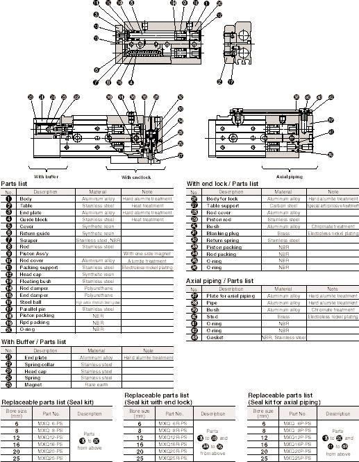
89 ir Slide Table Series MXQ Construction 91

90 Series MXQ Dimensions MXQ ir Slide Table 9
91 ir Slide Table Series MXQ Dimensions MXQ 93

92 Series MXQ Dimensions MXQ L/Symmetric Type ir Slide Table 9
93 ir Slide Table Series MXQ Dimensions MXQ L/Symmetric Type 9

94 Series MXQ Dimensions MXQ 8 ir Slide Table 9

95 ir Slide Table Series MXQ Dimensions MXQ 8 97

96 Series MXQ Dimensions MXQ 8L/Symmetric Type ir Slide Table 98

97 ir Slide Table Series MXQ Dimensions MXQ 8L/Symmetric Type 99


98 Series MXQ Dimensions MXQ 1 ir Slide Table 1


99 ir Slide Table Series MXQ Dimensions MXQ 1 11

100 Series MXQ Dimensions MXQ 1L/Symmetric Type ir Slide Table 1


101 ir Slide Table Series MXQ Dimensions MXQ 1L/Symmetric Type 13


102 Series MXQ Dimensions MXQ 1 ir Slide Table 1


103 ir Slide Table Series MXQ Dimensions MXQ 1 1


104 Series MXQ Dimensions MXQ 1L/Symmetric Type ir Slide Table 1

105 ir Slide Table Series MXQ Dimensions MXQ 1L/Symmetric Type 17

106 Series MXQ Dimensions MXQ ir Slide Table 18


107 ir Slide Table Series MXQ Dimensions MXQ 19


108 Series MXQ Dimensions MXQ L/Symmetric Type ir Slide Table 11

109 ir Slide Table Series MXQ Dimensions MXQ L/Symmetric Type 111


110 Series MXQ Dimensions MXQ ir Slide Table 11


111 ir Slide Table Series MXQ Dimensions MXQ 113


112 Series MXQ Dimensions MXQ L/Symmetric Type ir Slide Table 11


113 ir Slide Table Series MXQ Dimensions MXQ L/Symmetric Type 11


114 Series MXQ uto Switch/Proper Mounting Position at Detection of Stroke End ir Slide Table 11

115 ir Slide Table Series MXQ Made To Order 117


116 MXF Series Product Features...page 1 MXF Series How to Order...page 11 Specifications...page 1 Table Deflection...pages 13-1 Construction/ Parts List, Seal Kits...page 1 Dimensional Drawings...pages 1-19 uto Switch Specifications and Mounting...page 13 Please see safety instructions on page


117 MXF Series ø8, ø1, ø1, ø Low Profile Slide Table 1

118 Low Profile Slide Table MXF Series How To Order Preferred Option Program 11

119 MXF Series Specifications Low Profile Slide Table 1


120 Low Profile Slide Table MXF Series Table Deflection 13


121 MXF Series Table Deflection Low Profile Slide Table 1

122 Low Profile Slide Table MXF Series Construction / Parts Lists Packing List 1

123 MXF Series Dimensions MXF 8 Low Profile Slide Table 1

124 Low Profile Slide Table MXF Series Dimensions MXF 1 17
125 MXF Series Dimensions MXF 1 Low Profile Slide Table 18

126 Low Profile Slide Table MXF Series Dimensions MXF 19


127 MXF Series Low Profile Slide Table 13
128 Notes
129

130 MXW Series Product Features...pages MXW Series How to Order...page 13 Specifications...pages Operation Guide...pages 1-11 Table Deflection...page 1 Construction/ Parts List, Seal Kits...page 13 Dimensional Drawings...pages 1-13 uto Switch Specifications and Mounting...pages 1-1 Please see safety instructions on page
 7 1 1 1 17 7 3 Dual rod Work mounting Locating pin holes Repeatable mounting and removing of work. Easy alignment.")
131 MXW Series ø8, ø1, ø1, ø,ø Linear guide table provides long stroke Linear guide Long stroke (up to 3mm) Linear guide provides long stroke and smooth operation without vibration. MXW 8 MXW1 MXW1 MXW MXW Stroke (mm) Dual rod Work mounting Locating pin holes Repeatable mounting and removing of work. Easy alignment. Dual rod construction Slim design provides times the force of standard cylinder. MXW 8: ø8 x MXW1: ø1 x MXW1: ø1 x MXW: ø x MXW: ø x Body mounting Locating pin hole Thread for body mounting mounting types (body tapped, through hole) are available. Thread for mounting of work Helisert strengthens thread for mounting. to 8 threaded hole for secure mounting of work. Body tapped Through hole mounting 13


132 Table rigidity is constant through out entire stroke. Shock absorber Shock is absorbed at end stroke and provides a smooth stop. shock absorber that is built-into the table and recessed in the body permits a shorter overall length. Light weight Compact Model Width Height Length Weight MXW 8 MXW1 MXW1 MXW MXW Stroke 1mm pplicable as base for light pressing and transfer. Piping,Wiring Possible to pipe from directions. Can pipe and wire switches from the same side. uto switch can be attached to either side of body. Lateral piping / wiring Stroke adjuster Can adjust stroke One side: mm Both sides: 1mm Combine with the MXS slide for highly accurate applications. xial piping / wiring 13
133 MXW Series Long Stroke Slide Table How To Order MXW 1 1 B F9N L S Preferred Option Program uto switch pcs. S 1 pc. n n pcs. Bore size (Stroke mm) ø8 ø1 ø1 ø ø,,7,1,1,1,7,1,1,1 7,1,1,1,17, 1,1,1,17,,, 1,1,1,17,,,,7,3 uto switch lead wire length L.m 3m Option Standard (With urethane bumper) Type of auto switch B With shock absorbers pcs. Without auto switch Refer to below table for auto switch part number. pplicable auto switch / Read "Cautions for auto switch mounting" on page 1 before using auto switch. uto switch part no. Load voltage Lead wire Type Special Electrical Wiring length(m) Electrical entry Indicator function entry (Output) DC C. 3 Perpendicular In-line (Nil) (L) pplicable load 9V 9 Without V, 1V 1V or less IC circuit -wire V 93V 93 Reed Grommet 1V 1V switch With 3-wire 9V 9 (equivalent to NPN) V IC circuit F9NV F9N 3-wire (NPN) Relay F9PV F9P 3-wire (PNP) PLC F9BV F9B Solid state -wire Grommet With F9NWV F9NW switch Diagnosis 3-wire (NPN) V 1V F9PWV F9PW indication (-Color 3-wire (PNP) F9BWV F9BW indicaiton) -wire Lead wire length PLC: Programable logic controller.m " " (Example)93 3 m " L " 93L Refer to page 177 to 179 for additional information on auto switches. Stroke adjustment 1.Standard Lock nut Urethane bumper.with shock absorber(option) Shock absorber Lock nut Loosen the adjuster bolt lock nut on side,insert a hexagon wrench in the direction of the arrow to adjust the stroke,and then tighten the lock nut. B Stroke adjustment Loosen the adjuster bolt lock nut on side B,insert a hexagon wrench in the direction of the arrow to adjust the stroke,and then tighten the lock nut. bsorption stroke adjustment for shock absorber Loosen the adjuster bolt lock nut on side,insert a hexagon wrench in the direction of the arrow to adjust the stroke,and then tighten the lock nut. 13
 Stroke adjustment range MXW8 MXW1 MXW1 MXW ø8 x ø11 or its equivalent ø1 x ø17 or its equivalent M x.")
134 Long Stroke Slide Table MXW Series Specifications Specifications Model Bore size(mm) Port size Fluid ction Operating pressure Proof pressure mbient and fluid temperature Operating speed range Cushion Lubrication uto switch (Option) Stroke adjustment range MXW8 MXW1 MXW1 MXW ø8 x ø11 or its equivalent ø1 x ø17 or its equivalent M x.8 ø1 x ø3 or its equivalent ø x ø8 or its equivalent ir Double acting ~1psi {.1~.7 MPa} 1psi {1. MPa} 1 to 1 F ( 1 ~ C) ~ in/sec (~mm /s) Both ends urethane bumper (standard) Both ends shock absorber (option) Rc(PT)1/8 Non lube Reed switch Solid state switch ( wire, 3 wire) color indication solid state switch ( wire, 3 wire) One side:mm (Both sides:1mm) MXW ø x ø3 or its equivalent Precautions (1) The table is supported by precision bearings. Be careful not to apply strong impact or excessive moment when mounting work. () Select the best method for connection with the load having a supporting/guiding mechanism on its outside. lignment should be complete. (3) Scratches or dents on the sliding section of the piston rod may cause malfunction or air leakage. () When connecting fittings, do not allow dust or particles to enter actuator. Theoretical Output Table The dual rod ensures an output twice that of standard cylinders. Bore size (mm) Rod diameter (mm) Operating direction (Direction of operation) When viewed from size with lateral ports. Out: Cylinder extend In: Cylinder retract Piston area (in ) 8 1 OUT OUT.1.31 IN IN OUT IN OUT IN OUT 1. IN Note) Theoretical output (lbf) = Pressure(PSI) X Piston area (in ) In Out (Unit : lbf) Operating pressure (PSI) lbf =.8 N Cautions on use (1) Removing stopper block and adjuster bolt on both sides may cause trouble, use air slide table with adjust bolts mounted. () Cover the slide table when it is used in an environment that includes cutting dust, power dust (paper powder, thread dust, etc.) and cutting oil (gas oil, water, warm water, etc.) (3) No lubrication is required.however, when lubrication is desired, use turbine oil class 1 (ISO VG3). (Machine oil or spindle oil is not recommended.) Standard Stroke (mm) / Weight Table (lb) Model MXW MXW1 MXW1 MXW MXW Standard stroke (mm) lbf =.8 N 137
135 MXW Series Optional Specifications Long Stroke Slide Table Stroke djuster ssembly djuster assembly can be changed in the following manner. Quantity needed Change of adjuster assembly Parts Semi-standard Standard changed (-X11) Change stroke adjustment range Without shock absorber Change from mm to 1mm for one side Change With shock absorber + B Change to be with shock absorber dd B Change to be with shock absorber and stroke adjustment range from mm to 1mm Change + dd B Note 1) When only one side of stroke is changed, the quantity needed is the half of the above. Note ) Shock absorber must be ordered separately. How to Order MXW 1 1 X11 pplicable bore size ø8 ø1 ø1 ø ø djustment range X11 mm 1mm Standard Option Note 1) The above model number is one adjuster bolt assembly only. Note ) The air slide table already assembled with -X11 adjuster bolt assembly is not available. (Stopper side) B Mounting 1. Thread in the adjuster bolt from the direction of the arrow.. Fasten the lock nut from the direction of the arrow. Shock absorber and urethane bumper side Dimensions (mm) B D djuster bolt Lock nut C M pplicable size MXW 8 MXW1 MXW1 MXW MXW Model MXW-81 MXW-81-X11 MXW-11 MXW-11-X11 MXW-11 MXW-11-X11 MXW-1 MXW-1-X11 MXW-1 MXW-1-X11 djustment range (mm) B C.. 3 D M Mx. Mx.8 Mx1 M8x1. M1x1. 1mm 1mm Maintain a minimum adjustment of at least 1mm from the end blocks. Shock absorber or urethane bumper may not operate effectively and damage may result. 138
136 Long Stroke Slide Table MXW Series Optional Specifications Shock bsorber Specifications Shock absorber model RB8 RB8 RB17 RB11 RB1 Suitable slide table MXW8 MXW1 MXW1 MXW MXW Max. absorbing energy J (kgf m).98(.1).9(.3).88(.) 19.() 8.8() bsorbing stroke (mm) Max. collision speed ~ in/sec (.~ m/sec) Max. operating frequency (cycle/min) Max. allowable thrust lbf (N) mbient temperature range 33 (17) () 9 () 183 (81) 1 (191) 1~17 F (-1~8 C) Spring force lbf (N) Weight (oz) t expanding. (1.9). (1.9).9 (.) 1. (.8) 1.87 (8.3) t compressing.8 (3.83).9 (.) 1. (.8) 3.9 (1.98).1 (.) How to Change Shock bsorber (1) Removal Stopper block*. Remove the shock absorbers. Stroke adjuster block* 1. Loosen the shock absorber fixing screws. () Mounting * In case of MXW8-, first take out the adjuster block, and then the shock absorber. Tighten the mounting bolt with the torque.7 in lb (.3 N m) when assembling the adjuster block. 1. Mount the shock absorbers. Insert to the end of the mounting hole of table.. Tighten the shock absorber fixing screws with the recommended torque shown in the table below. Torque Type MXW 8 MXW1 MXW1 MXW MXW Fixing thread size M3 x M3 x M3 x M x M x Recommended torque in lbf (N m).3 (.).3 (.).3 (.) 7.1 (.8) 8.9 (1) Hexagonal wrench width across flats
137 MXW Series Operation Guide Long Stroke Slide Table Maximum dynamic load and allowable moments are different depending on work mounting orientation,cylinder mounting direction and piston speed. Select correct size MXW according to the operating limit value in the graph applicable to operating condition of the application. Not to exceed total ( α n) < 1 α n = Movable load (W) Max.movable load (W max.) + Static moment (M) llowable static moment (M max.) + Dynamic moment (Me) llowable dynamic moment (Me max.) < 1 1 W max., M max. and Me max. values are according to graph 1, and 3 below. Movable load Max.movable load (N) Model W MXW 8 18 MXW1 MXW1 7 MXW 11 MXW 17 1N =.8 lbf Moment llowable moment (Static moment / movable moment) N m Model Pitch moment Yaw moment Roll moment Mp/Mep My/Mey Mr MXW 8 3 MXW1 1 1 MXW1 1 MXW MXW Pitch moment M p=w (L1 + ) Mp Static moment W Mp L1 W Dynamic moment We= δ W V V = 1.Va We : Collision equivalent load (N) δ : Bumper coefficient With urethane bumper (standard) = /1 With shock absorber - = 1 / 1 W : Load (N) V : Collision speed (mm/s) Va : verage speed(mm/s) 1 L1 W W Mp Mep (Pitch moment) My Mey (Yaw moment) (Graph) Moment due to work load when cylinder is at rest. 1: Correction value for moment center distance (mm) MXW 8 39 MXW1 8 MXW1 8 MXW 7 MXW 97 : Correction value for moment center distance (mm) MXW 8 MXW1 MXW1 MXW MXW Moment N m Yaw moment M y=w (L + B) B1: Correction value for moment center distance (mm) My W W 1 3 Piston speed mm/s MXW 8 MXW1 MXW1 MXW MXW My Moment due to impact of load at end of stroke. Pitch moment M ep=*1/3 We (L3 + C) *verage load factor We C : Correction value for moment center distance (mm) MXW 8 1 MXW1 1 MXW1 1 MXW MXW 8 W L B L MXW MXW MXW1 MXW1 MXW8 Mep V B1 C L3 7 1N m =.737 ft lb B: Correction value for moment center distance MXW 8 MXW1 MXW1 MXW MXW (mm) W Movable load N Mr (Roll moment) Moment N m Piston speed mm/s (Graph1) 1N =.8 lbf (Graph3) 1N m =.737 ft lb Mr W W Mey V MXW MXW MXW1 MXW1 MXW8 MXW MXW MXW1 MXW Piston speed mm/s Roll moment M r=w (L3 + C) C1: Correction value for moment center distance (mm) MXW 8 1 MXW1 1 MXW1 1 MXW MXW 8 C: Correction value for moment center distance (mm) MXW 8 3 Mr MXW1 9 MXW1 37 MXW 9 MXW 3 Yaw moment M ey=*1/3 We (L + B) B : Correction value for moment center distance (mm) We MXW 8 3 MXW1 9 MXW1 37 MXW 9 MXW 3 MXW8 L3 L3 C C1 L B
138 Long Stroke Slide Table Calculation for Selection For selection of a proper model,find load factors (α n) and make sure that their sum total ( α n) does not exceed 1 (one). α n = α 1 + α + α 3 < 1 MXW Series Operation Guide Item (1) Max. movable load () Static moment (3) Dynamic moment Load factors α n α 1 =W/Wmax. α =M/Mmax. α 3 =Me/Memax. Note Examine W. W max. is maximum movable load at Va. Examine Mp,My,and Mr. M max. is allowable moment at Va. Examine Mep and Mey Me max. is allowable moment at V. V: Collision speed Va: verage speed Calculation example Va Operating condition Cylinder: MXW1 Cushion: Standard (Urethane bumper) Mounting: Horizontal wall mounting Speed (verage): Va=3 {mm/s} Load: W =1 {N} {Except arm section weight} L3= {mm} L= {mm} W L {B L3 Item Load factors α n Note (1) Max. movable load B L W α 1 = W/W max. =1/7 =.13 Examine W. W : W max. value is from <Graph> at Va=3mm/s C L3 () Static moment W M r=w (L3 + C) = 1 (. +.1) =. [N m] Examine M r. (M p,m y values do not apply to this example.) L3+C M r α =M r/m r max. =./1 =.3 M r: M r max. value is from <Graph3> at Va=3mm/s (3) Dynamic moment M ey W e W L+B M ey=1/3 We (L + B) From V = 1. Va We = δ W V = / = 18 [N] M ey = 1/3 18 (. +.37) =.9 [N m] α 3 = M ey/m ey max. =.9 / 1.3 =.33 Examine M ey. M ey: Calculate W e for impact condition Bumper coefficient δ = /1 (With urethane bumper) M ey max. value is from <Graph> at V=1.Va=mm/s W e M ep L3+C M ey =1/3 W e (L3 + C) = 1/3 18 (. +.1) = 3.8 [N m] Examine M ep. M ep: From above formula W e=18 α 3' = M ep/m ep max. = 3.8 /1.3 =. M ep max. value is from <Graph> at V=1.Va=mm/s α n = α 1 + α + α 3 + α 3' = =.789 α n =.789 < is < 1, pplication is approved. 11
139 MXW Series Table Deflection Long Stroke Slide Table Table deflection by pitch moment Table deflection by yaw moment Table deflection by roll moment Table pitch deflection due to static pitch moment applied at arrow for fully extended stroke of slide table Table yaw deflection due to static yaw moment applied at arrow for fully extended stroke of slide table. Table roll deflection arrow due to static roll moment applied at arrow F when Lr=(see table) and table is retracted. Deflection on when the load is applied at F. Deflection on when the load is applied at F. Deflection on when the load is applied at F. L F L=mm L F L=mm F MXW8, MXW1, MXW1 Table deflection quantity mm.3 MXW8 MXW1 MXW1..1 MXW8, MXW1, MXW1 Table deflection quantity mm.3 MXW8 MXW1 MXW1..1 L L=mm MXW8, MXW1, MXW1 Table deflection quantity mm.1.8. MXW8 MXW1 MXW Load N 1N =.8 lbf Load N 1N =.8 lbf Load N 1N =.8 lbf MXW, MXW MXW, MXW MXW, MXW Table deflection quantity mm..1 MXW MXW Table deflection quantity mm..1 MXW MXW Table deflection quantity mm.8... MXW MXW Load N 1N =.8 lbf Load N 1N =.8 lbf Load N 1N =.8 lbf 1
140 Long Stroke Slide Table MXW Series Construction / Parts List Packing List Parts List No. Description 1 Body Table 3 End plate Stroke adjuster block Rail Guide block 7 Rod 8 Piston ass'y 9 Rod cover 1 Head cap 11 End cap 1 Floating bushing 13 Floating bushing B 1 Stopper 1 Stroke adjuster bolt 1 Orifice 17 bsorber shaft 18 djust bumper Material luminum alloy luminum alloy luminum alloy luminum alloy High carbon chrome bearing steel High carbon chrome bearing steel Stainless steel luminum alloy Resin Resin Stainless steel Stainless steel Stainless steel Carbon steel Brass luminum alloy Polyurethane Note Hard anodized Hard anodized Hard anodized Hard anodized Heat treatment Heat treatment With magnet Heat treatment Electroless nickel plating, Heat treatment Electroless nickel plating Chromate treatment Seal List No Description Piston seal Rod seal "O" ring Material NBR NBR NBR MXW8 MXW8-PS Seal Kit Part No. MXW1 MXW1 MXW MXW1-PS MXW1-PS MXW-PS MXW MXW-PS 13
141 MXW Series Dimensions MXW ø8 Stroke:, Long Stroke Slide Table Operating port -M x.8 (mm) Width across hexagon socket hole. J 1 Scale :3%. Width across flats 8 øh9 +.3 depth. H9 {.3 depth. -M x.7 thread depth (Helisert) Operating port M x.8 Operation direction (Plug: M-P) Y 8 Operation direction B Y 1. Operating port M ~.8 Operation direction B (Plug: M-P) ø7 ø Z 1.8 Cross section (scale %) N-M x.7 thread depth 8 Bottom through hole 3.3 (N-1) x H H G H9 +.3 depth. øh9 +.3 depth. F E Model MXW8- MXW8- E 3 F 8 7 G 7 H 3 3 N 3 J 71 Note) djuster bolt Y shown in the section above is attached only on B type(with shock absorber). Z
142 Long Stroke Slide Table MXW Series Dimensions MXW ø8 Stroke: 7, 1, 1, 1 Width across hexagon socket hole. Operating port -M x.8 J 1 (mm) Scale: 3%. Width across flats 8 øh9 +.3 depth. H9 +.3 depth. -M x.7 thread depth (Helisert) 1 38 Y Y 8 L K Z N-M x.7 thread depth Bottom through hole 3.3 (N-1) x H H H9 +.3 depth. G HH GG NN-M x.7 thread depth 8 Bottom through hole 3.3 øh9 +.3 depth. F E Model MXW8 7 MXW8 1 MXW8 1 MXW8 1 E F G GG 19 3 H HH 3 3 J K L N 7 NN 1 1 Z
143 MXW Series Dimensions MXW ø1 Stroke:, 7 Long Stroke Slide Table Width across hexagon socket hole. Operating port -M x.8 J 1. (mm) Scale: 3% Width across flats 8 H9 +.3 depth. -M x.7 thread depth (Helisert) Operating port M x.8 Operation direction (Plug : M-P) 7 8 øh9 +.3 depth Y Operation direction B Y. Operating port M x.8 Operation direction B (Plug : M-P) ø9 ø Z Cross section (scale %) -M x.8 thread depth 1 3 x H G Bottom through hole. H H9 +.3 depth. F E øh9 +.3 depth. Model MXW1- MXW1-7 E 8 3 F G H 3 J 8 89 Z 3 Note) djuster bolt Y shown in the section above is attached only on B type(with shock absorber). 1
144 Long Stroke Slide Table MXW Series Dimensions MXW ø1 Stroke: 1, 1, 1 Width across hexagon socket hole. Operating port -M x.8 J 1 (mm). Scale: 3% Width across flats 8 H9 +.3 depth. -M x.7 thread depth (Helisert) 7 8 Y øh9 +.3 depth L Y K 3. Z N-M x.8 thread depth 1 (N-1) x H G Bottom through hole. H H9 +.3 depth. GG M x.8 thread depth 1 Bottom through hole. F E øh9 +.3 depth. Model MXW1-1 MXW1-1 MXW1-1 E F G GG H 3 3 J K 3 8 L N Z
145 MXW Series Dimensions MXW ø1 Stroke: 7, 1 Long Stroke Slide Table Width across hexagon socket hole 3 Operating port -M x (mm) Scale: 3% 8 Width across flats 1 7 H9 +.3 depth. -M x.8 thread depth 9 (Helisert) Operating port M x.8 Operation direction (Plug : M-P) øh9 +.3 depth Operating port M x.8 Operation direction B (Plug : M-P) ø ø Y Operation direction B Y Z 1. Cross section (scale %) -M x 1 thread depth 1 Bottom through hole ø.1 3 x H G H 7 H9 +.3 depth. F E øh9 +.3 depth. Model MXW1-7 MXW1-1 E 83 8 F 11 1 G H Z 7 9 Note) djuster bolt Y shown in the section above is attached only on B type (with shock absorber). 18
146 Long Stroke Slide Table MXW Series Dimensions MXW ø1 Stoke: 1, 1, 17, Width across hexagon socket hole 3 Operating port -M x.8 J 1 (mm) Scale: 3% 8 Width across flats 1 7 H9 +.3 depth. -M x.8 thread depth 9 (Helisert) Y øh9 +.3 depth Y L 1 K 31 N-M x 1 thread depth 1 (N-1) x H G Bottom through hole ø.1 H Z H9 +.3 depth. NN-M x 1 thread depth 1 HH GG Bottom through hole ø.1 F E øh9 +.3 depth. Model E F G GG H HH J K L N NN Z MXW \ MXW \ MXW MXW
147 MXW Series Dimensions MXW ø Stroke: 1, 1 Long Stroke Slide Table Width across hexagon socket hole Operating port -Rc (PT) 1/8 1 1 (mm) Scale: % Width across flats 13 H9 +.3 depth. 7 8-M x.8 thread depth 13 (Helisert) Operating port Rc (PT) 1/8 Operation direction Taper thread plug with hexagonal hole Y øh9 +.3 depth. 1 Operation direction 1 B Y 1 8 Operating port Rc (PT) 1/8 Operation direction B Taper thread plug with hexagonal hole ø1. ø Z Cross section (scale %) -M x 1 thread depth 1 Bottom through hole ø.1 x H G H 7 H9 +.3 depth. øh9 +.3 depth. F E Model MXW-1 MXW-1 E F G H 8 Z Note) djuster bolt Y shown in the section above is attached only on B type (with shock absorber). 1
148 Long Stroke Slide Table MXW Series Dimensions MXW ø Stoke: 1, 17,,, Width across hexagon socket hole Operating port -Rc (PT) 1/8 J (mm) Scale: % 1 Width across flats 13 øh9 +.3 depth. H9 +.3 depth. 7 8-M x.8 thread depth 13 (Helisert) Y 1 Y L 11 K Z 3. N-M x 1 thread depth 1 Bottom through hole ø.1 (N-1) x H H 7 H9 +.3 depth. G HH GG NN-M x 1 thread depth 1 Bottom through hole ø.1 F E øh9 +.3 depth. Model MXW-1 MXW-17 MXW- MXW- MXW- E F G GG H HH 8 J K L N NN Z
149 MXW Series Dimensions MXW ø Stroke: 1, 1, 1 Long Stroke Slide Table Width across hexagon socket hole Operating port -Rc (PT) 1/8 J (mm) Scale:1% 11 Width across flats 17 ø8h9 +.3 depth 9 8H9 +.3 depth M x 1 thread depth 18. (Helisert) Operating port Rc (PT) 1/8 Operation direction Taper thread plug with hexagonal hole Y 37 Y 8 9 Operation direction 3 B 11 Operating port Rc (PT) 1/8 Operation direction B Taper thread plug with hexagonal hole ø13 ø Z 3 Cross section (scale 3%) (N-1) x H G N-M8 x 1. thread depth 1 Bottom through hole ø. H 9 8H9 +.3 depth 9 ø8h9 +.3 depth 9 F E Model MXW-1 MXW-1 MXW-1 E F 1 1 G H J N Note) djuster bolt Y shown in the section above is attached only on B type(with shock absorber). Z 39 1
150 Long Stroke Slide Table MXW Series Dimensions MXW ø Stroke: 17,,,, 7, 3 Width across hexagon socket hole Operating port -Rc (PT)1/8 J (mm) Scale: 1% 11 Width across flats 17 ø8h9 +.3 depth 9 8H9 +.3 depth M x 1 thread depth 18. (Helisert) Y 37 Y 9 L K 7 38 Z N-M8 x 1. thread depth 1 Bottom through hole ø. (N-1) x H G H 9 8H9 +.3 depth 9 HH GG NN-M8 x 1. thread depth 1 Bottom through hole ø. ø8h9 +.3 depth 9 F E Model MXW-17 MXW- MXW- MXW- MXW-7 MXW-3 E F G GG 7 8 H HH J K L N NN Z
151 1 MXW Series Long Stroke Slide Table 1 1 uto Switch / Suitable Mounting Position at Stroke End Detection B W V Reed switch: D-9 (V), D-93 (V), D-9 (V) MXW 8 MXW1 MXW1 MXW MXW B W V B W V B W V B W V B W V Switch operation range Stroke (mm) Solid state switch: D-F9B (V), D-F9N (V), D-F9P (V) MXW 8 MXW1 MXW1 MXW MXW B W V B W V B W V B W V B W V Switch operation range 3 (3.) 3 (3.) (.) (.) (.) Stroke (mm) ( ) values for D-F9BV F9NV F9PV Model Model
152 Long Stroke Slide Table MXW Series color indication solid state switch: D-F9BW (V), D-F9NW (V), D-F9PW (V) Model MXW 8 MXW1 MXW1 MXW MXW B W V B W V B W V B W V B W V Stroke (mm) Switch operation range. 7 7 uto Switch Mounting Set screw(attached to auto switch) uto switch Precision screwdriver Use the screwdriver with grip diameter to mm when set screw (attached to auto switch) is set. Tightening torque should around.~.89 in lb. 1
153

154 MXP Series Product Features...pages MXP Series How to Order...page 1 Specifications...page 11 Table ccuracy...page 1 How to Select...pages 13-1 Table Deflection...page 1 Construction/ Parts List, Seal Kits...page 1 Dimensional Drawings...pages uto Switch Specifications and Mounting...pages 171 Please see safety instructions on pages
155 MXP Series ø, ø1, ø1, ø1 Traveling parallelism :.mm Parallelism:.mm Traveling parallelism Traveling parallelism on guide block side Traveling parallelism on guide block top side Run out indication when body is fixed on standard base and cylinder is fully extended. MXP1,1,1 Cylinder with built-in linear guide. High rigidity and high accuracy Cylinder is built into rail of linear guide. Stroke adjustable Compact stroke adjuster (Standard option). Stroke adjustment : 3mm on one side mm on both sides Body mounting tap Work mounting tap uto switch mountable Switch rail and magnet are optional. Piping flexibility directions from lateral and vertical direction are available. Work mounting Multiple mounting options Mounting from 3 directions. 1. Tapped holes on table top. Tapped holes on table side 1. Body tapped. Through hole 3. Body side tapped 18
156 Cylinder with built-in linear guide Compact design, but large allowable moment. Comparison of MXP and MXF Model MXP1-1 MXF1- Width 1. 8 Height ll dimensions in mm. Note 1) t fully stroke extended. Total length 9 Note1) Pitch moment 3.3 ft lbf (. N m) 1. ft lbf (1. N m) MXP/MXF.7 times Various auto switches available Reed switch, solid state switch and -Color indication solid state switch can be attached. MXPJ Compact : Height 17 Width Compact shape is realized by integrating cylinder with linear guide of guide block. Free Piping Piping possible in two directions: body side or in-line. Mounting on equipment is possible from top side (through hole) and bottom side body tapped. 1.Body tapped.through hole pplication examples Positioning of printed circuit board Precision positioning of pallet Series variation Model Bore size (mm) Standard stroke (mm) Stroke adjuster uto switch MXPJ ø MXP1 MXP1 MXP1 ø1 ø1 ø1 Standard option Reed switch:d-9, D-9 V Solid state switch:d-f9, D-F9 V -Color indication solid state switch: D-F9 W, D-F9 WV 19
157 Series MXP How To Order Precision ir Slide Table MXP 1 1 F9N S Precision ir Slide Table Preferred Option Program Bore sizestandard stroke(mm) 1 1, 1 1, 1, 3 uto switch suffix pcs. S 1 pc. n n pcs. N Note 1 uto switch With magnet and rail Without magnet and rail Note 1) uto switch can not be mounted on N type (Without magnet and rail). See page 1 for accessory part numbers to add auto switch magnet and rail to N type cylinder. Type of auto switch Without auto switch Refer to below table for auto switch part number. pplicable auto switch / Read "Cautions for auto switch mounting" on page 171 before using auto switch. uto switch part no. Load voltage Lead wire Type Special Electrical Wiring length(m) Electrical entry Indicator pplicable load function entry (Output) DC C. 3 Perpendicular In-line (Nil) (L) 9V 9 Without V, 1V 1V or less IC circuit -wire V 93V 93 Reed Grommet 1V 1V switch With 3-wire 9V 9 (equivalent to NPN) V IC circuit F9NV F9N 3-wire (NPN) Relay F9PV F9P 3-wire (PNP) PLC F9BV F9B Solid state -wire Grommet With V 1V F9NWV F9NW switch Diagnosis 3-wire (NPN) F9PWV F9PW indication 3-wire (PNP) (-Color F9BWV F9BW indicaiton) -wire Lead wire length PLC: Programable logic controller.m " " (Example)93 3 m " L " 93L Refer to page 177 to 179 for additional information on auto switches. 1
158 Precision ir Slide Table Series MXP Specifications Model Bore size (mm) Piping port Fluid ction MXP1 ø1 MXP1 ø1 M.8 ir Double acting MXP1 ø1 Operating pressure mbient and fluid temperature Operating speed range Cushion Lubrication Stroke adjuster Stroke adjusting range to 1psi {.1 to.7 MPa} -1 to 1 F (-1 to C) to in/sec ( to mm/s) Bumper Not required Standard option Each to 3mm at both ends Reed switch ( wire, 3 wire) uto switch Solid state switch ( wire, 3 wire) Color indication solid state switch ( wire, 3 wire) Tolerance of stroke length +1 mm 1 psi =.73 kgf/cm MXPJ/ Precision air slide table Precision ir Slide Table How to Order MXPJ with auto switch is not available. MXPJ 1 Standard stroke mm 1 1mm Preferred Option Program Theoretical Output Table Bore size (mm) Standard Stroke Model MXP1 MXP1 MXP1 Weight Table Model MXP1-1 MXP1- MXP1-1 MXP1- MXP1- MXP1-3 Piston area (in ) Standard stroke (mm) 1, 1,, 3 Body weight Operating pressure (psi) dditional weight of magnet and rail (oz) 1 oz = 8.39 g (lbf) psi =.9 MPa 1 lbf =.8 N Specifications Bore size (mm) Piping port Fluid ction Operating pressure mbient and fluid temperature Operating speed range Bumper Lubrication Tolerance of stroke length Theoretical Output Table Bore size (mm) Piston area (in ) Standard Stroke Model MXPJ Standard stroke (mm), 1 ø M3. ir Double action to 1psi {.1 to.7 MPa} -1 to 1 F(-1 to C) to in/sec ( to mm/s) Rubber bumper Not required +1 mm Operating pressure (MPa) psi =.73 kgf/cm (lbf) lbf =.8N Weight Table Model MXPJ- MXPJ-1 (oz) Body weight oz = 8.39 g 11
159 Series MXP Table ccuracy Precision ir Slide Table D B C M Traveling parallelism D side parallelism to B side C side parallelism to side ccessories Rail assembly for auto switch mounting When auto switch is mounted on air slide table without rail for auto switch mounting (MXP - N), this ass'y is used. Dimensions -M 3 (Cross recessed head machine screw for precision instrument) W Port Distance from of gauge dial when guide block is moved full stroke after body is fixed on basic bases. C side parallelism to side Parallelism D side parallelism to B side Travelling C side parallelism to side parallelism D side parallelism to B side Dimension tolerance of M Dimension tolerance of W (Unit:mm) MXPJ MXP1 MXP1 MXP1 Non-rotating accuracy Radial clearance.... ±. ±. -M3 8 (Bolt with hex. hole) pplicable size Part no. of switch rail MXP1-1 MXP-D1-1 MXP1- MXP-D1- MXP1-1 MXP-D1-1 MXP1- MXP-D1- MXP1- MXP-D1- MXP1-3 MXP-D1- Note) MXP1- and MXP1- are common. MXP1-3 and MXP1- are common. Note With magnet and mounting screw Radial clearance Fixed body Radial clearance (µm) Table non-rotating accuracy (deg) MXPJ MXP1 MXP1 MXP1 ± ±3 ± ±7 ±.3 ±.3 ±. ±. 1
160 Precision ir Slide Table Series MXP How to Select Selection Procedure Formula and Data Selection Example 1 Operating conditions Enumerate the operating conditions according to mounting position and work form. Kinetic energy Calculate kinetic energy E(J) of moment. Check that kinetic energy of moment does not exceed allowable kinetic energy. Model used Mounting position verage speed Va(mm/s) llowable load W(N) : Fig.1 Over hung Ln(mm) : Fig. 1 N =.8 lbf 1 mm/s =.39 in/s L3+3 Cylinder : MXP1-1 Mounting : Lateral wall mounting verage speed : Va=3[mm/s] L=mm L3=3mm 1 W V 1 E= ( ) E= ( ) = Collision speed=1. Va V=1. 3= Corrected coefficient Kinetic energy (E)<llowable kinetic energy(e max.) Possible to use by E=.18<E max.=. llowable kinetic energy E max. : Table 1 L W 3 Load rate 3-1 Load rate of moment Calculate allowable load Wa(N). Calcurate load rate (α1) of moment. 3- Load rate of static moment Calculate static moment M(Nm). Calculate allowable static moment Ma(Nm). Calculate load rate (α) of static moment. 3-3 Load rate of kinetic moment Calculate kinetic moment Me(Nm). Calculate allowable kinetic moment Mea(Nm). Calculate load rate (α3) of kinetic moment. 3- Sum of load rate When sum of load rate does not exceed 1, it is possible to use. Wa=β W max. llowable load coefficient β : Graph 1 Max.allowable load W max. : Table α1=w/wa M=W(Ln+n)/1 Corrected value for center position distance of moment n : Table 3 Ma=γ M max. llowable moment coefficient γ : Graph Max.allowable moment M max. : Table α=m/ma (Ln+n) Me=1/3We 1 Load equivalent to collision We= W V/1 Corrected value for center position distance of moment n : Table 3 Mea=γ M max. llowable moment coefficient γ : Graph Max.allowable moment M max. : Table α3=me/mea α1+α+α3<1 Wa=1 1=1 β=1 W max.=1 α1=/1=.17 Examine for Mr [s Mp and My does not arise, Examination is not needed.] Mr=(+.8)/1=. =.8 Mar=1.=. γ =1 Mr max.=. α=./.=.13 Examine for Mep (+.8) Mep=1/3 33. =.3 1 We= /1=33. =.8 Meap=.7 1.7=1.19 γ =.7 Mp max.=1.7 α3=.3/1.19=. Examine for Mey (3+1.) Mey=1/3 33. =. 1 We=33. 1=1. Meay=1.19 (Same as Meap) α'3=./1.19=.378 α1+α+α3+α'3= =.81<1 nd it is possible to use. 13
161 Series MXP How to Select Precision ir Slide Table How To Order Fig. 1 llowable load:w(n) W W Fig. Over hung:ln(mm), Corrected value for center position distance of moment:n(mm) Pitch moment Yawing moment Roll moment Static moment L1 1 L L3 3 Mp Mr My W W L W L1 1 L3 3 Mp My Mr W W W W Kinetic moment We Mep L We Mey L3 3 Table 1 llowable kinetic energy:e max.(j) llowable kinetic energy MXPJ.1 MXP1. MXP1.7 MXP1.13 MXP1 3 1 J =.737 ft lb 1 N =.8 lbf Corrected value for center position distance Table 3 of moment : n(mm) Corrected value for center position distance of moment : n(mm) Stroke MXPJ MXP MXP1 8 1 MXP Table MXPJ MXP1 MXP1 MXP1 Symbol Max. allowable moment : M max.(n m) Pitch/Yawing moment : Mp max./my max. Stroke (mm) Symbol n(n=1~3) E Emax Ln(n=1~3) M(Mp,My,Mr) Ma(Map,May,Mar) Me(Mep,Mey) Mea(Meap,Meay) M max.(mp max.,my max.,mr max.) Note) Static moment : Moment by gravity Kinetic moment : Moment by stopper collision Table MXPJ MXP1 MXP1. Max.allowable load:w max.(n) Roll moment :Mr max. Stroke (mm) Definition Corrected value for center position distance of moment Kinetic energy llowable kinetic energy Over hung Static moment (Pitch, Yawing, Roll) llowable static moment (Pitch, Yawing, Roll) Kinetic moment (Pitch, Yawing) llowable kinetic moment (Pitch, Yawing) Max. allowable moment (Pitch, Yawing, Roll) Max. allowable load N m =.737 ft lbf Unit mm J J mm Nm Nm Nm Nm Nm Graph 1 llowable load coeficient β llowable moment γ Symbol V Va W Wa We llowable load coeficient:β verage speed Va mm/s Graph llowable moment coeficient:γ verage speed Va mm/s Collision speed V mm/s Note) verage speed is used at static moment calculation. Collision speed is used at kinetic moment calulation. W max. α β γ Definition Collision speed verage speed Load llowable load Load equivalent to collision Max.allowable load Load rate llowable load coeficient llowable moment coeficient Unit mm/s mm/s N N N N 1 mm/s =.39 in/s 1 J = 1 N m =.737 ft lbf 1 mm =.39 in 1 N =.8 lbf 1
162 Precision ir Slide Table Series MXP Table Deflection Table deflection when pitch moment is applied. Deflection on when load is applied on F. F Table deflection when yawing moment is applied. Deflection on when load is applied on F. F Table deflection when roll moment is applied. Deflection on when load is applied on F. F L 1 N =.8 lbf L L ø L=8mm ø L=8mm ø Table deflection (mm) Table deflection (mm) Table deflection (mm) Table deflection (mm) MXPJ- MXPJ Load (N) ø1 L=1mm ø1 L=1mm ø1 MXP1-1 MXP1-8 Load (N) ø1 L=1mm ø1 L=1mm ø1 MXP1-1 MXP1-1 1 Load (N) ø1 L=1mm ø1 L=1mm ø1 MXP1- MXP Load (N) Table deflection (mm) Table deflection (mm) Table deflection (mm) Table deflection (mm) Load (N) MXP1-1 MXPJ- MXP1-8 Load (N) MXP1-1 MXP1-1 1 Load (N) MXP1- MXPJ-1 MXP Load (N) Table deflection (mm) Table deflection (mm) Table deflection (mm) Table deflection (mm) MXPJ- 1 3 Load (N) MXP Load (N) MXP Load (N) L=8mm MXPJ-1 L=1mm MXP1- L=1mm MXP1- MXP1- MXP1-3 L=1mm 1 3 Load (N) 1 N =.8 lbf 1
163 Series MXP Construction Precision ir Slide Table MXP1,1, Parts list No. Description Material Note Body Guide block End plate Cover Return guide Scraper Tube Joint valve Joint shaft djust bumper Stainless steel Stainless steel luminum alloy Resin Resin Brass Stainless steel Stainless steel Polyurethane Heat treatment Heat treatment Hard anodized Electroless nickel plated Parts list No. Description Material Note Orifice Steel ball djusting bolt djusting nut Plug Switch rail* Magnet* Magnet holder* Piston seal Brass High carbon chrome bearing steel Carbon steel Carbon steel Brass luminum alloy Rare earth Brass NBR Electroless nickel plated Nickel plated Nickel plated Electroless nickel plated Hard anodized Electroless nickel plated *See page 1 for ordering information. Replaceable parts list (Seal kit) Bore size(mm) Part No. Contents 1 MXP1-PS 1 MXP1-PS pieces of No.19 1 MXP1-PS MXPJ Parts list No. Description Material Note Body Table Cover Return guide Scraper Piston Joint shaft End cap Rod bumper Steel ball Plug "O" ring Piston seal Stainless steel Stainless steel Resin Resin Brass Carbon steel Brass Polyurethane High carbon chrome bearing steel Brass NBR NBR Heat treatment Heat treatment Electroless nickel plated Electroless nickel plated Electroless nickel plated Electroless nickel plated Replaceable parts list (Seal kit) Bore size (mm) Part no. MXPJ-PS Contents pieces each of No.1 and 13 1
164 Precision ir Slide Table Series MXP Dimensions ø MXPJ Scale:1% -M3., 3 deep H 13 D 18 1± B F -M.7 Bottom hole diameter ±. Piping port -M3. (Plug:M-3P) Stroke : S M 1 B D - Base side for mounting. J Z Piping port -M3. (mm) Model F H J M S Z MXPJ MXPJ
165 Series MXP Dimensions ø1 Precision ir Slide Table MXP1 3 Z Scale: 7% -M3., deep V K -M3., 3 deep Max. 3. G M N Stroke:S 1.7 Width across flats 1. Width across flats M3. 13 MXP1-1 H. Piping port -M.8 (Plug:M-P) ±. -M.7 Bottom hole diameter 3.3 W 1 -M3. deep B.±. D Piping port -M J 9. 1 B D Mounting base side cross MXP1- Without magnet and switch rail -M3., 3. deep For rail mounting 8 -M., 3 deep For magnet mounting.7. -M3. deep 1 1 L (mm) Model MXP1-1 MXP1- G 8 H 3 J. 8. K 3 L 3 M 1 39 N. 7. S 1 V 7 W Z 9 18
166 Precision ir Slide Table Series MXP Dimensions ø1 MXP1 3 -M.7, deep Z V K -M3., deep Scale:% G Max. 3 M 7. Stroke:S MXP1-1 Width across flats 18. Width across flats M H Piping port -M.8 (Plug:M-P) ±. -M.8 Bottom hole diameter. W -M.7. deep B.±. D Piping port -M J 9. 1 B D Mounting base side cross MXP1- Without magnet and switch rail -M3., 3. deep For rail mounting 8 -M., 3 deep For magnet mounting.7 L 3. -M.7. deep (mm) Model MXP1-1 MXP1- G 1 3 H J 8 98 K L M 9 9 S 1 V 9 89 W 7 Z
167 Series MXP Dimensions ø1 Precision ir Slide Table MXP1 3 -M.8, 8 deep Z V K Scale: % Without magnet and switch rail -M3., 3. deep For rail mounting 8 -M., 3 deep For magnet mounting Max. M 11 G -M.7, deep Stroke:S MXP1-.7 Width across flats 3 Width across flats 8 M H Piping port -M.8 (Plug:M-P) ±. -M 1 Bottom hole diameter.1 W 3 -M.8 7 deep B 8.±. D Piping port -M J B D Mounting base side cross MXP1-3 L -M.8 7 deep (mm) Model MXP1- MXP1-3 G 18 8 H 8 7 J K L 3 M S 3 V 8 18 W 7 Z
168 Precision ir Slide Table Mounting on MXP1-1 When MXP1-1 has in-line piping, the auto switch may obstruct speed controller and fitting. uto switch Obstruct Speed controller Obstruct Series MXP Suitable mounting position for detection of auto switch / stroke end Electrical entry from outside Cautions for uto Switch Mounting Read before use. Table of auto switch which obstructs speed controller and fitting uto switch type Electrical entry Wiring uto switch model no. Solid state switch 3-wire D-F9P In-line D-F9 -wire D-F9B 3-wire D-F9NW,D-F9PW color indication In-line -wire D-F9BW solid state switch D-F9 W Perpendicular 3-wire -wire D-F9NWV,D-F9PWV D-F9BWV Electrical entry from inside B B Install auto switch as shown in figure below. 1.Use perpendicular piping port..reverse mounting direction of the auto switch which obstructs fitting. Reverse the mounting direction Parallel electrical entry B Caution Tool for auto switch mounting Use the screwdriver with grip diameter to mm when set screw (attached to auto switch) is set. Tightening torque Tightening torque should around. to.89 in lb (. to.1nm). When you begin to feel that the screw is being tightened, turn it an additional 9. uto switch mounting uto switch Set screw (ttached to auto switch) Screwdriver (Grip diameter to mm) Reed switch D-9(V), D-93(V), D-9() Stroke (mm) Type MXP1 B.. MXP1 B MXP1 B 31 Solid state switch D-F9B(V), D-F9N(V), D-F9P(V) Type MXP1 MXP1 MXP1 B B B Stroke (mm) mm Switch operating range mm Switch operating range 3 Color indication solid state switch D-F9BW(V), D-F9NW(V), D-F9PW(V) Type MXP1 MXP1 MXP1 B B B Stroke (mm) mm Switch operating range 171
169 ; ; ; ; ; ; ; ; ; ; ; ; ; ; ; ; ; ; ; ; ; ; ; ; ; ; ; ; ; Q Q Q Q Q Q Q Q Q Q Q Q Q Q Q Q Q Q Q Q Q Q Q Q Q Q Q Q Q
170 uto Switches uto Switch Precautions...pages Reed Switch D-9/3-wire, -wire...page 177 D-F9/3-wire, -wire...page 178 -color Indication Solid State Switch D-F9 W/3-wire, -wire...page 179 Solid State Switch Connections and Examples...page
171 Series MX uto Switch Precautions 1 Read Before Handling Warning 1.Confirm specifications. Read specifications carefully and use this product appropriately. The product may be damaged or malfunction if it is used outside the range of specifications of current load, voltage, temperature or impact..take precautions when multiple cylinders are used close together. When multiple auto switch cylinders are used in close proximity, magnetic field interference may cause the switches to malfunction. Maintain a minimum cylinder separation of mm. 3.Pay attention to length of time that switch is ON at an intermediate stroke position. When setting up an auto switch at an intermediate position of stroke and driving a load, although auto switch would operate, load will not operate satisfactorily as the length of operating time will be shortened if speed is too fast. Detectable maximum piston speed is: uto Switch operating range (mm) V(mm/s) = x 1 Time load applied (ms). Wiring should be kept as short as possible. <Reed contact> When a length of the wire toward load gets longer, the initial current at switching on would be greater to shorten the product's life. (The switch will stay ON all the time.) 1) For an auto switch without a protection circuit or contact point, use a contact point protection box for the wire length m or longer. ) Even for auto switch with a built-in protection circuit or contact point, if the wire is 3m or longer, the initial current would not be absorbed thoroughly and it may shorten the product's life. <Solid state > lthough wire length should not affect switch function, use a wire length of 1mm or shorter. Designing / Selection.Take precautions for internal voltage drop of switch. <Reed contact> 1) Switches with an indicator light (Except "D-9, 9V") If auto switches are connected in series as shown below, take precautions that there will be a large voltage drop because of internal resistance of light emitting diode. (Refer to internal voltage drop in auto switch specifications.) [Voltage drop will be as much as n times when n auto switches are connected.] lthough an auto switch operates normally, load may not operate. Operating under specified voltage, although an auto switch operate normally, load may not operate. Confirm minimum operating voltage of load and the following formula will apply. Supply internal voltage voltage drop of switch > ) If internal resistance of light emitting diode causes a problem, select switches without an indicator light( Model "D-9, 9V"). <Solid state > 3) Generally, internal voltage drop will be greater with wire solid state auto switch than with reed switch. Take the same precaution as 1). lso, note that DC1V relay is not applicable..pay attention to leakage current. <Solid state > With wire solid state auto switch, current (leakage current) flows to a load to operate internal circuit even on the OFF status. Operating current of load (OFF condition) > Load minimum operating voltage of load Leakage current If criteria given by above formula is not met, it will not reset correctly (stays on). Use 3 wire switch if this specification will not be satisfied. Leakage current flow to load will be as much as n times when n auto switches are connected in parallel. Slide Tables 7.Do not use load that generates surge voltage. <Reed contact> If driving a load such as relay that generates a surge voltage, use switch with a built-in protection circuit of contact point or use a contact point protection box. <Solid state > lthough zener diode for protection from surge is connected at the output side of solid state auto switch, it may still cause damage if surge will be repeatedly applied. When a load like relay or solenoid which generates surge is directly driven, use a type of switch with built-in surge absorption element. 8.Note for using interlock circuit When auto switch is used for an interlock signal for high reliability, build a double interlock system to prepare against troubles that setup a mechanic protective function or use a switch (sensor) other than an auto switch. Perform periodic maintenance and confirm proper operation. 9.Keep working clearances around actuation enough for maintenance. When designing application, be sure to allow for sufficient clearances for maintenance and inspection requirements. 17
172 Slide Tables Series MX uto Switch Precautions Read Before Handling Mounting and djustment Warning 1. Do not drop or bump. Do not drop, bump or apply excessive impacts (3m s or more for reed switch and 1m s or more for solid state switch) while handling. lthough the body of the switch may not be damaged, inside of switch could be damaged and it may cause malfunction.. Do not carry a cylinder by the auto switch lead wire. Never carry a cylinder by its lead wire. This not only causes a broken lead wire, it causes internal elements of the switch to be damaged by the stress. 3. Mount a switch within the limits of its tightening torque. When a switch is tightened beyond its limits of tightening torque, the mounting screws, mounting bracket or switch may get damaged. On the other hand, tightened under the limits of tightening torque, it may cause displacement of mounting position of a switch. (Refer to Page for how to mount, how to move or tightening torque etc.). Set a switch at the center of operating range. Set a mounting position of an auto switch to adjust that a piston stops at the center of the operating range (the ranges that a switch is ON). (The mounting position shown in a catalog indicates the most optimized position at stroke end.) Setting at the end of operating range (around the borderline of ON and OFF), the operation will be unstable. Warning 1.void repeatedly bending or stretching lead wires. Broken lead wires will result from applying a force of bending stress or stretching to lead wire..make sure to connect the load before power is applied. < wire> If power is ON at a time when an auto switch is not connected to a load, the switch is instantly damaged because of an excess current. 3.Confirm proper insulation against wiring. Ensure proper insulation (contact with other circuits, ground fault, improper insulation between terminals etc.) at wiring. It causes a damage as an excess current flow into a switch..do not wire with power lines or high voltage lines. Wire separately with power lines or high voltage lines, avoiding to wire with these lines in parallel or in a same wiring pipe. Control circuits including auto switches may malfunction from noises of other voltage lines..do not short circuit with loads. <Reed contact> If power is ON at a status that loads are short circuit, the switch is instantly damaged because of an excess current flow into switch. <Solid state > protection circuit against short-circuit is not built-in for the models of D-F9 (V), F9 W(V) and all models of PNP output type. If loads are short circuited, the switch is instantly damaged. Take special care to avoid reverse wiring with a power supply line (brown) and a output line (black) on 3 wire type. Color changes of lead wire Color of core wire for SMC's auto switch lead wire has been changed according to No. NEC shown in the right tables successively for the production after September 199. Please take special cautions for the polarity of each wire while both previous color and new wire Output (+) Output (-) Wiring Previous color Red Black. void wrong wiring. <Reed contact> DCV switch with indicator light has a polarity. brown lead line or the first terminal is (+). Blue lead line or the second terminal is (-). 1) If a connection is reversed, a switch will operate, however light emitting diode will not be lit. lso note that a current flow more than specified will damage light emitting diode and will not operate. Models applied: D-93, 93V <Solid state > 1) If connection is reversed on a wire type switch, a switch will not be damaged if protected by a protection circuit, however switch will always stay in ON status. However it is still necessary to take care not to reverse connection since switch could be damaged by a load short circuit in this condition. ) If connection is reversed (reversed power supply line + and power supply line -) on 3 wire type switch, a switch will be protected by protection circuit. However, with a connection power supply line (+) to blue line and power supply line (-) to black line, switch will be damaged. New color Brown Blue Solid state with diagnostic output Previous color New color Power supply + Power supply GND Output Diagnostic Output Red Black White Yellow Brown Blue Black Orange 3 wire Power supply + Power supply GND Output Power supply + Power supply GND Output Latch type diagnostic Output Previous color Red Black White Previous color Red Black White New color Brown Blue Black Solid state latch type with diagnostic output New color Brown Blue Black Yellow Orange 17
173 Series MX uto Switch Precautions 3 Read Before Handling Slide Tables Warning 1.Never use in an atmosphere with explosive gas. Structure of auto switches is not intended to prevent explosion. Never use in an atmosphere with an explosive gas since it may cause an explosion..do not use in an area where magnetic field is generated. uto switches will malfunction or magnets inside cylinders will become demagnetized. (Consult SMC for availability of a high magnetic field auto switch.) 3.Do not use in an environment continually exposed to water. lthough switches (except a few models) meet IEC standard IP7 structure (JIS C 9: anti-immersion structure), do not use switches in applications where continually exposed to water splash or spray. Poor insulation or swelling of potting resin inside switches may cause malfunction..do not use in an environment with oil or chemicals. Consult SMC when auto switches will be used under the environment with coolant, cleaning solvent, various oil or chemicals. Even for a short period of time that auto switches are used under these condition, they may be adversely affected by improper insulation, malfunction by swelling of potting resin or hardening lead wires.. Do not use in an environment of temperature cycle. Consult SMC if switches are used under temperature cycle other than normal temperature changes as they may be adversely affected..do not use in an environment that has excessive impact shock. <Reed contact> When excessive impact (3m/s or more) is applied to a reed switch during operation, the contact point will malfunction and generate or cut off the signal for instantaneous (1ms or less). Consult SMC for necessity of using a solid state switch according to an environment. Environment 7.Do not use in the area where surge is generated. <Solid state > When there are units (solenoid type lifter, high frequency induction furnace, motor etc.) in which great surge is generated around cylinders with a solid state auto switch, it may deteriorate or damage the switch. void sources of generating surge and disorganized lines. 8.void accumulation of iron powder or close contact of magnetic substance. When a large amount of ferrous powder like machining chips or spatter is accumulated or magnetic substance (something magnet attracts) is brought in close proximity to auto switch cylinder, it may cause auto switch to malfunction as magnetic force inside cylinder would be lost. Maintenance Warning 1.s auto switches may malfunction unexpectedly and would not be able to secure safety, perform following maintenance periodically. 1) Secure and tighten switch mounting screws. If screws were loosened or mounting position dislocated, tighten them after the mounting position is readjusted. ) Confirm that there is not any damage to lead wires. To prevent improper insulation, change switches or repair lead wires if damages are discovered. 3) Confirm lighting of green light on color indicator light. Confirm a green LED light is lit and stop at the adjusted position. If a red LED light is lit, mounting position is not appropriate. Readjust mounting position until green LED becomes lit. Misc. Warning 1.Consult SMC concerning water proof efficiency, elasticity of lead wires, and usage at welding site. 17

174 Slide Tables Series MX Reed Switch D-9/3-wire, -wire uto Switch Specification Part no. Electrical entry Wiring pplicable load D-9 In-line D-9V IC circuit, relay PLC D-93 Perpendicular In-line -wire Relay, PLC PLC: Programmable logic controller D-93V Perpendicular D-9 In-line 3-wire IC circuit D-9V Perpendicular Load voltage Load current range and max. load current Contact protection circuit Internal voltage drop Indicator light C V DC or less / m C 8V DC or less / m C 1V DC or less / m None VDC / to m 1VC / to m to 8VDC / m None.V or less.8v or less Light on red LED at ON uto Switch Internal Circuit D-9(V) Reed switch D-93(V) Reed switch D-9(V) Reed switch LED LED Resistor Zener diode Resistor Reverse current check diode Brown Blue Brown Black Load Blue Contact protection box CD-P11 CD-P1 Contact protection box CD-P11 CD-P1 (+) (-) Brown Blue DC electric power supply Lead wire Oil proof vinyl cabtire cable, ø.7,.m D-9(V), D-93(V).18mm cores (Brown, Blue) D-9(V).1mm 3 cores (Brown, Black, Blue) Insulation resistance MΩ or more under the test voltage VDC (between case and cable) Withstand voltage 1VC/1min. (between case and cable) Operating time 1ms Shock resistance 3m/s {3.G} Contact Protection Box Model CD-P11 CD-P1 Operating voltage 1VC VDC Length of lead wire Switch connecting side.m Load connecting side.m mbient temperature: 1 to 1 F (-1 to C) Leakage voltage Protective structure IEC9 standard IP7 (JISC9) Water-proof structure Please suffix "L" to the part no. in case of 3 meter lead wire (Ex.) D-9L Contact Protection Box Internal Circuit CD-P11 Surge absorber CD-P1 Condenser Choke coil Choke coil Resistor Brown Blue (+) Brown (-) Blue uto Switch Dimensions D-9 M. l Mounting thread Slotted head screw.7 D-93 / D-9 M. l Slotted head screw Indicator light.7 D-93V / D-9V M. l Slotted head screw.8 (3).8 (3). D-9V M. l Slotted head screw 1 Most sensitive position. (3) 1 Most sensitive position uto Switch Weight Type Lead wire length.m Lead wire length 3m D D-9V 8 1 D-9 type switch have no built-in contact protection circuit. Use this box for inductive loads, meters or more of lead wires, or 1VC applications. D-9(V) type switch is used for 1VC or less, since there is no voltage limitation you can select a suitable model for your needs. D D-93V 8 1 D Unit : g D-9V 8 1 Indicator light.7. 1 Most sensitive position (3) Most sensitive position 177

175 Series MX D-F9/3-wire, -wire Slide Tables uto Switch Specification Part no. Electrical entry Wiring Output type pplicable load Power voltage Current consumption Load voltage Load current Internal voltage drop Leakage voltage Indicator light D-F9N In-line NPN type D-F9NV Perpendicular 8m or less 8VDC or less.v or less 3-wire D-F9P In-line 1, VDC(1 to 8VDC) m or less 1µ or less at VDC Lead wire Oil proof vinyl cabtire cable, ø.7,.m D-F9N(V), D-F9P(V).1mm 3 cores (Brown, Black, Blue) D-F9B(V).18mm cores (Brown, Blue) Insulation resistance MΩ or more under the test voltage VDC (between case and cable) Withstand voltage 1,VC/1 min. (between case and cable) Indication light Light at ON PNP type D-F9PV Perpendicular VDC relay, PLC 1m or less 1.V or less Light on red LED at ON PLC: Programmable logic controller D-F9B In-line -wire D-F9BV Perpendicular VDC(1 to 8VDC) to 3m.V or less 1m or less at VDC mbient temperature 1 to 1 F (-1 to C) Operating time 1ms or less Collision resistance 1m/s {1G} Protective structure IEC9 standard IP7 (JISC9) Water-proof structure Please suffix "L" to the part no. in case of 3 meter lead wire. (Ex.) D-F9NL uto Switch Weight Type D-F9N Lead wire length.m. Lead wire length 3m 3. D-F9P D-F9B D-F9NV D-F9PV Unit : g D-F9BV. 31 uto Switch Internal Circuit uto Switch Dimensions D-F9N(V) Brown D-F9N / D-F9P / D-F9B Mounting thread M. l Slotted head screw Main switch circuit Output Black.8 Indicator light.7 D-F9P(V) Main switch circuit Blue Brown Output Black. L Most sensitive position (3) Part no. D-F9N D-F9P D-F9B L dimensions (mm).. D-F9B(V) Blue Brown D-F9NV / D-F9PV / D-F9BV..8 Mounting thread M. l Slotted head screw Indicator light Main switch circuit Blue (3) Most sensitive position 178

176 Slide Tables uto Switch Internal Circuit D-F9NW(V) Main switch circuit Brown Output Black uto Switch Specifications Part no. Electrical entry Wiring Output pplicable load Power voltage Current consumption Load voltage Load current Internal voltage drop Leakage current Indicator light uto Switch Weight Type Lead wire length.m Lead wire length 3m D-F9NW In-line NPN type D-F9NWV Perpendicular 3-wire D-F9PW In-line 1, VDC(1 to 8VDC) 1m or less 8VDC or less D-F9NW. 3.V or less m or less PNP type D-F9PWV Perpendicular 1m or less 1.V or less Series MX -color Indication Solid State Switch D-F9 W/3-wire, -wire D-F9BW In-line -wire D-F9BWV Perpendicular VDC(1 to 8VDC) to 3m V or less 1µ or less at VDC 1m or less at VDC Operating position: Light on red LED Most suitable operating position: Light on green LED Lead wire Oil proof vinyl cabtire cable, ø.7,.m D-F9NW(V), D-F9PW(V).1mm 3 cores (Brown, Black, Blue) D-F9BW(V).18mm cores (Brown, Blue) Insulation resistance MΩ or more under the test voltage VDC (between case and cable) Withstand voltage 1,VC/1 min. (between case and cable) mbient temperature 1 to 1 F (-1 to C) Operating time 1ms or less Collision resistance 1m/s {1G} Please suffix "L" to the part no. in case of 3 meter lead wire (Ex.) D-F9NWL D-F9NWV. 33. VDC Relay, PLC D-F9PW. 33. PLC: Programmable logic controller D-F9PWV. 3 D-F9BW. 33. Unit : g D-F9BWV. 33. uto Switch Dimensions D-F9PW(V) Blue Brown D-F9NW / D-F9PW / D-F9BW..8 Mounting thread M. l Slotted head screw Indicator light.7 Main switch circuit D-F9BW(V) Main switch circuit Brown Blue Output Black Blue D-F9NWV / D-F9PWV / D-F9BWV Most sensitive position (3) Mounting thread M. l Slotted head screw Indicator light Indicator light / Display method Operating range ON Display Red Green Red OFF The most suitable operation position (3) Most sensitive position 179
Series MXH/ ø6, ø10, ø16, ø20
 Compact Slide Series / ø, ø, ø, ø The use of an endless track linear guide produces a table cylinder having excellent rigidity, linearity and non-rotating accuracy. CL MLG CNA CNG MNB CNS CLS CB CV/MVG
Compact Slide. Series MXH ø6, ø10, ø16, ø20
 Compact Slide Series ø, ø, ø, ø The use of an endless track linear guide produces a table cylinder having excellent rigidity, linearity and non-rotating accuracy. Endless track linear guide Series Variations
/ ø6, ø10, ø16, ø20 A table cylinder suitable for short pitch mounting
 roduces a table cylinder non-rotating accuracy MXH / ø, ø, ø1, ø A table cylinder suitable for short pitch mounting Application example Auto switches offer numerous variations Reed switches, solid state
240% 19% reduced. Compact Slide. MXH Series. Improved by up to. With new high rigidity linear guide. 369g. ø6, ø10, ø16, ø g.
 Compact Slide Series ø, ø, ø, ø RoHS Allowable moment MXS Improved by up to MXQ MXQ 2% MXF MXW MXJ MXP MXY With new high rigidity linear guide MTS Allowable moment improvement illustrated below Allowable
Precision Cylinder. MTS Series. ø8, ø12, ø16, ø20, ø25, ø32, ø40 MXH MXS MXQ MXQ MXF MXW MXJ MXP MXY MTS D- -X. Series Variations MTS8
 Precision Cylinder Series, ø, ø6, ø, ø, ø, ø MXS Series Variations Model 8 Standard stroke (mm) 7 7 Rod end configuration Cushion Rubber bumper End lock Made to Order Rod Variable stroke/ through-hole
Series MXU ø6, ø10, ø16
 Compact Slide Series ø, ø, ø1 Displacement accuracy against moments Table edge displacement M1(Pitch moment): 0.02mm or less M2(Yaw moment): 0.01mm or less The miniature linear guide improves the linear
Air Slide Table. Traveling parallelism: mm. Mounting from the through-holes on the top. Tapped for mounting a work piece
 ir Slide Table Series Height: mm/width: mm/length: mm () Front mounting accuracy: 0.01 mm Top mounting accuracy: 0.0 mm Traveling parallelism: 0.00 mm Note 1) Note ) Integrated front mounting part and
Low Profile Slide Table. Series MXF. ø8, ø12, ø16, ø20. Body mounting(body tapped)
") Low Profile Slide Table Series XF ø, ø, ø1, ø Slim and compact style air slide table has parallel design for guide and cylinder. Standard stroke adjustment can be adjusted at each stroke end within mm
Low Profile Slide Table Series XF ø, ø, ø1, ø Slim and compact style air slide table has parallel design for guide and cylinder. Standard stroke adjustment can be adjusted at each stroke end within mm
Two Hand Control Valve
 Two Hand Control Valve Series n output is available through synchronized, twohanded operation (within 0.5 s)! Conforming to EN574 RoHS (Interchangeable with XT92-67 ) Example of a basic circuit diagram
CAT.ES C. Compact Guide Cylinder. SeriesMGP. ø12, ø16, ø20, ø25, ø32, ø40, ø50, ø63, ø80, ø100. New end lock type introduced to Series MGP
 CT.S-7 C Compact Guide Cylinder Series ø, ø, ø, ø2, ø, ø, ø, ø, ø, ø0 New end lock type introduced to Series . Top mount Compact Guide Cylinder Series ø, ø, ø, ø2, ø, ø, ø, ø, ø, ø0 Four mounting types
Air Slide Table. Traveling parallelism: mm. Mounting from the through-holes on the top. Tapped for mounting a work piece
 ir Slide Table Series Height: mm/width: mm/length: mm () Front mounting accuracy: 0.01 mm Top mounting accuracy: 0.0 mm Traveling parallelism: 0.00 mm Note 1) Note ) Integrated front mounting part and
Miniature Guide Rod Cylinder ±0.1. Mounting from 2 directions
 Miniature Guide Rod Cylinder Series Non-rotating accuracy : Height ±0.1 Mounting from 2 directions idth Overall length Two auto switches can be mounted even for mm strokes Integral wiring/piping to one
Series MXH. ø6, ø10, ø16, ø20. Compact Slide
 CAT.E27- Compact Slide Series MXH ø, ø, ø1, ø The use of an endless track linear guide produces a table cylinder having excellent rigidity, linearity and non-rotating accuracy. The use of an endless track
ROD SLIDERS INDEX ACTUATORS GENERAL CATALOG. Characteristics 779. Handling Instructions, and Precautions 783
 Presenting our CAD drawing data catalog ACTUATORS GENERAL CATALOG ROD SLIDERS INDEX Characteristics 779 Handling Instructions, and Precautions 783 Standard Cylinders Specifications 785 Order 78 Dimensions
Mini Free Mount Cylinder
 Mini Free Mount Cylinder Series ø, ø, ø, ø, ø, ø1, ø Series 1 ction Stroke 1 2 0 0 0 Clean uto switch series None Rod end Male threaded Without thread Solid state switch D-F D-M9 D-M9 W Female threaded
ø20, ø32 ø50, ø63, ø80 How to Order Piping direction Flange side Nil Cylinder stroke 15mm 15 (RSH20) 20mm 20 (RSH32) 30 D L Cylinder stroke
 20mm 20 (RSH32) 30 D L Cylinder stroke") Heavy Duty Stopper Cylinder Series RSH/RS1H ø, ø32 ø, ø63, ø How to Order Piping direction Flange side Nil Positional relationship of lever and port RSH Port Direction of transfer 32mm Bore size only 32
Heavy Duty Stopper Cylinder Series RSH/RS1H ø, ø32 ø, ø63, ø How to Order Piping direction Flange side Nil Positional relationship of lever and port RSH Port Direction of transfer 32mm Bore size only 32
Series MHZJ2. How to Order MHZJ2 16 D F9PV. Body option. Nil. Port. Port
 Parallel Type ir Gripper How to Order 1 1 2 Bore size mm 1mm 1mm 2mm mm MHZJ2 1 D F9PV Number of fingers 2 2 fingers D S C ction Double acting Single acting (normally open) Single acting (normally closed)
CAT.ES20-53 E. Dual-Rod Cylinder. Series CXS. CXS Dual-Rod Cylinder with Air Cushion Compact Type Series CXSJ. New:
 CAT.ES-3 E Dual-Rod Cylinder Series New: Dual-Rod Cylinder with Air Cushion Compact Type Series J Dual-Rod Cylinder with guide function for pick-and-place applications Series! Twice the thrust Non-rotating
Compact Guide Cylinder Series MGQ
 Compact Guide Cylinder Series ø, ø, ø, ø, ø, ø, ø, ø, ø, ø0 ir cylinder with guide integrated that has achieved anti-lateral load and high non-rotating accuracy. Space-saving cylinder. Suitable as stoppers
MULTI SLIDERS CONTENTS
 CAD drawing data catalog is available. ACTUATORS GENERAL CATALOG CONTENTS Features 923 Handling Instructions and Precautions 925 Specifications 929 Order Codes 930 Inner Construction 931 Dimensions 932
Series MGP. Compact Guide Cylinder. New end lock type introduced to Series MGP. ø12, ø16, ø20, ø25, ø32, ø40, ø50, ø63, ø80, ø100
 Compact Guide Cylinder Series ø, ø, ø, ø2, ø, ø, ø, ø, ø, ø0 New end lock type introduced to Series.22- CL MLG CN CNG MNB CNS CLS CB CV/MVG CXW CXS CXT MX MXU MXH MXS MXQ MXF MXW MXP MG MGQ MGG MGC MGF
Specifications. Standard Stroke Table. Bore size (mm) Number of axes 200, 300, 400, 500,
 Number of axes 200, 300, 400, 500,") Series REH Specifications Bore size mm Fluid ction Maximum operating pressure Minimum operating pressure Proof pressure mbient and fluid temperature Piston speed ubrication Stroke length tolerance Piping
Series REH Specifications Bore size mm Fluid ction Maximum operating pressure Minimum operating pressure Proof pressure mbient and fluid temperature Piston speed ubrication Stroke length tolerance Piping
Traveling parallelism: mm. Mounting from the through-holes on the top. Tapped for mounting a work piece
 ir Slide Table Series RoHS Height: mm/width: mm/length: mm () Traveling parallelism: 0.00 mm Note 1) Front mounting accuracy: 0.01 mm Note ) Top mounting accuracy: 0.0 mm Integrated front mounting part
22mm Space required between the bottom of the cylinder body and your equipment is reduced.
 Compact Guide Cylinder ø2,,, ø2,,, ø0, ø63,, ø0 With air cushion Water resistant cylinder are now available. New Up to 7% Weight reduced! New Weight reduced by up to 7% with a shorter guide rod and thinner
Compact Guide Cylinder
 Compact Guide Cylinder Series ø, ø, ø, ø, ø, ø, ø, ø, ø, ø ir cylinder with guide integrated that has achieved anti-lateral load and high non-rotating accuracy. Space-saving cylinder. Suitable as stoppers
Low Profile Slide Table Series MXF ø8, ø12, ø16, ø20
 Low Profile Slide Table Series XF ø, ø, ø1, ø Low-profile and compact type, air slide table with the construction of guide and cylinder aligned in parallel. eat appearance Protecting stopper section with
Air Slide Table. ø8, ø12, ø16, ø20, ø25. Linear guide table provides long stroke. Table rigidity is constant throughout entire stroke.
 ir Slide Table Series MX ø, ø2, ø, ø2, ø2 inear guide table provides long stroke. Table rigidity is constant throughout entire stroke. ong stroke (Max. mm) inear guide provides long stroke, and it obtains
Guide Table. ø40, ø63, ø100
 Guide Table Series MGF ø, ø, ø Low-profile compact cylinder utilizes a large concentric guiding sleeve to provide excellent eccentric load resistance. Mounting height greatly reduced Low-profile cylinder
Guide Table. MGF Series
 Guide Table MGF Series ø, ø, ø0 Low-profile compact cylinder utilizes a large concentric guiding sleeve to provide excellent eccentric load resistance. Mounting height greatly reduced Low-profile cylinder
49.5 mm Overall. 30 mm MXZ ø20. Compact. Compact Cylinder with Linear Guide. MXZ Series CAT.ES20-236A. ø12, ø16, ø20, ø25. MXZ ø20, 10 mm stroke.
 Compact Cylinder with Linear Guide ø12, ø16, ø20, ø25 RoHS Compact 49.5 mm Overall length MXZ ø20, 10 mm stroke 30 mm MXZ ø20 Width Design and assembly time is reduced due to integration of a linear guide
240 g. 290 g. Compact and lightweight. Electric Actuators. Series LEPY/LEPS. Miniature Rod Type/Miniature Slide Table Type
 Electric ctuators Series LEPY/LEPS Miniature Rod Type/Miniature Slide Table Type Step Motor (Servo/2 VDC) and lightweight Rod Type Series LEPY Weight 2 g LEPY6-2 RoHS Maximum pushing force: N Positioning
CAT.ES20-53 E -UK. Dual-Rod Cylinder. Series CXS. CXS Dual-Rod Cylinder with Air Cushion Compact Type Series CXSJ. New:
 CAT.ES-3 E -UK Dual-Rod Cylinder Series New: Dual-Rod Cylinder with Air Cushion Compact Type Series J Dual-Rod Cylinder with guide function for pick-and-place applications Series! Twice the thrust Non-rotating
Compact Type Dual-Rod Cylinder
 CAT.ES-74 A Compact Type Dual-Rod Cylinder ø, ø, ø2, ø32 additionally released. Series CXSJ /ø, ø0, ø, ø, ø2, ø32 Auto switches can be installed from 3 directions. Reverse mounting Dimensions/Weight Overall
SLIDE TABLES CONTENTS
 CAD drawing data catalog is available. ACTUATORS GENERAL CATALOG SLIDE TALES CONTENTS Features 979 Safety Precautions, Handling Instructions and Precautions 981 Specifications 985 Order Codes 986 Inner
High Rigidity/ High Precision Guide Type ø50, ø63. The use of two linear guides allows a maximum load of 320kg. (ø63) Rodless cylinder MY1BH SMC
 Rodless cylinder MY1BH SMC") MYHT Series High Rigidity/ High Precision Guide Type ø, ø6 The use of two linear guides allows a maximum load of kg. (ø6) Rodless cylinder MYBH SMC 2 linear guides Easy maintenance is stressed by a revolutionary
MYHT Series High Rigidity/ High Precision Guide Type ø, ø6 The use of two linear guides allows a maximum load of kg. (ø6) Rodless cylinder MYBH SMC 2 linear guides Easy maintenance is stressed by a revolutionary
Dual rod cylinder with guide function suitable for pick & place applications. Adjustable stroke range: 0 to 5 mm. Axial foot piping.
 Dual Rod Cylinder / Series ø,,,,, Dual rod cylinder with guide function suitable for pick & place applications. Ball bushing bearings and slide bearings are standard for all series. Dimensions for ball
Series CYP. ø15, ø32 Clean Rodless Cylinder. How to Order
 ø15, ø32 Clean odless Cylinder How to Order CYP 15 200 Y59 Clean rodless cylinder Cylinder bore size 15 15 mm 32 32 mm Standard stroke ore size (mm) Standard stroke (mm) 100, 150, 200, 250, 300, 350 15/32
Angular Style Air Gripper
 Angular Style Air Gripper Series /A/M 15 Angular style air gripper Series /A/M - Auto switch is attachable. 8 mm x 0 mm x mm g Body option (Only for A-) Side piping Port Port A- Short body. 1 mm x 0 mm
Low Profile Air Gripper. Series MHF2. Low profile air gripper with space-saving design is newly released. 5-77
 Low Profile Air Gripper Low profile air gripper with space-saving design is newly released. 5-77 Low Profile Air Gripper Height is approximately / the size of an equivalent Series MHZ2. MHZ2-D 42 Bore
Magnetically Coupled Rodless Cylinder Slider Type: Ball Bushing Bearing. How to Order CY1L 25 H 300 J79W. Load voltage 5 V 200V 100 V 12 V 5 V, 12 V
 Magnetically Coupled Rodless Cylinder Slider Type: all ushing earing Series CY1L ø, ø, ø, ø, ø, ø, ø How to Order CY1L H 00 J79W Slider type (all bushing bearing) mm mm mm mm mm mm mm Magnetic holding
Rotary Actuators Precautions 1 Be sure to read this before handling.
 Precautions 1 1. Confirm the specifications. Products represented in this catalog are designed only for use in compressed air systems (including vacuum). Do not operate at pressures or temperatures, etc.,
Free Mount Cylinder. Series CU. A space-saving air cylinder with multiple surfaces capable of mounting directly. Offered in rich variations.
 Free Mount Cylinder Series CU A space-saving air cylinder with multiple surfaces capable of mounting directly. Offered in rich variations. Space-saving The multiple surface direct mounting with a square
Slide Unit. CX2/CXWM/CXWL Series. Slide Bearing/CX2:ø10, ø15, ø25 CXWM:ø10, ø16, ø20, ø25, ø32 Ball Bushing Bearing/CXWL:ø10, ø16, ø20, ø25, ø32
 Slide Unit CX/M/L Series Slide Bearing/CX:ø0, ø, ø5 M:ø0, ø, ø0, ø5, ø3 Ball Bushing Bearing/L:ø0, ø, ø0, ø5, ø3 Provided with shock absorbers to absorb impact and noise. The slide unit can absorb energy
Slide Unit. Bore size. ø15 (2) ø10 (2) ø16 (3) ø20 (2) Ball bushing bearing Slide bearing. ø25 (3) (3) ø32 (3)
 ø10 (2) ø16 (3) ø20 (2) Ball bushing bearing Slide bearing. ø25 (3) (3) ø32 (3)") Slide Unit Series CX/M/L Slide Bearing/CX:ø, ø, ø5 M:ø, ø6, ø0, ø5, ø3 Ball Bushing Bearing/L:ø, ø6, ø0, ø5, ø3 Provided with shock absorbers to absorb impact and noise. The slide unit can absorb energy
Slide Unit Series CX/M/L Slide Bearing/CX:ø, ø, ø5 M:ø, ø6, ø0, ø5, ø3 Ball Bushing Bearing/L:ø, ø6, ø0, ø5, ø3 Provided with shock absorbers to absorb impact and noise. The slide unit can absorb energy
Soft Start-up Valve. AV2000/3000/4000/5000 Series
 Soft Start-up Valve V000/000/000/000 Series [Option] C- R- W- C R - W - Start-up valve for low speed air supply to gradually raise initial pressure in an air system and for quick exhaust by cutting off
Doc. no.mx*-omp0038-d PRODUCT NAME AIR SLIDE TABLE. MODEL / Series / Product Number
 Doc. no.mx*-omp0038-d PRODUCT NAME AIR SLIDE TABLE MODEL / Series / Product Number MXQ6(A,B)-**Z* MXQ8(A,B,C)-**Z* MXQ12(A,B,C)-**Z* MXQ16(A,B)-**Z* MXQ20(A,B)-**Z* MXQ25(A)-**Z* Contents 1. Pr oduc t
Free Mount Cylinder. Series. Series CU CAT.EUS20-95 B -UK. Space-saving. Auto Switch Capable P. 4, 23, 37 P. 45 P. 43
 CAT.EUS- B -UK Free Mount Cylinder A space-saving air cylinder with multiple surfaces capable of direct mounting. Offered in many variations. Space-saving The multiple surface direct mounted rectangular
Dual rod cylinder with guide function for pick & place applications.
 Dual Rod Cylinder Series CXS ø, ø0, ø, ø, ø2, Dual rod cylinder with guide function for pick & place applications. Series CXS Twice the thrust Non-rotating accuracy ±0. MX MY CY MG CX - Ball bushing bearings
Guide Table. Series MGF
 Guide Table Series MGF ø, ø, ø0 Low-profile compact cylinder utilizes a large concentric guiding sleeve to provide excellent eccentric load resistance. Mounting height greatly reduced Low-profile cylinder
Dual rod cylinder with guide function suitable for pick & place applications. Adjustable stroke range: 0 to 5 mm. Axial foot piping.
 Dual Rod Cylinder J/ Series ø, ø, ø, ø, ø, Dual rod cylinder with guide function suitable for pick & place applications. Ball bushing bearings and slide bearings are standard for all series. Dimensions
Series MGC ø20, ø25, ø32, ø40, ø50
 Compact Guide Cylinder Series MGC ø, ø, ø, ø, ø Linear Transfer Unit with compact guide body and front plate Grease nipple offers easy lubrication for bearings Compact front plate and guide body Space
Design & Selection. Installation & Adjustment
 U SM Series WRNING This product must not be used submerged in water, oil or powder, or where coolant, coolant fluid or swarf, etc., may come in contact. lways incorporate an interlock in the control circuit
Series MGF ø40, ø63, ø100
 Guide Table Series MGF ø, ø, ø How to Order MGF Z7 Guide table Number of auto switches 2 S 1 Cylinder bore size/ Standard stroke,, 7,,, 7,,, 7, Auto switch Without auto switch * Refer to the table below
SeriesMHZL2 How to Order
 Parallel Type ir Gripper Long Stroke SeriesMHZL2 How to Order 1 2 2 ore size Number of fingers 2 2 fingers 1mm mm 2mm 2mm MHZL2 D S C ction Double acting Single acting (normally open) Single acting (normally
Compact Guide Cylinder
 Compact Guide Cylinder Series ø2, ø, ø, ø2, ø, ø, ø, ø, ø, ø0 Series standard type and series high precision ball bushing bearing type (except with end lock) products have been remodeled for a lightweight
Air Slide Table. ø8, ø12, ø16, ø20, ø25. Linear guide table provides long stroke. Table rigidity is constant throughout entire stroke.
 ir Slide Table Series MX ø, ø2, ø, ø2, ø2 inear guide table provides long stroke. Table rigidity is constant throughout entire stroke. ong stroke (Max. mm) inear guide provides long stroke, and it obtains
Compact Hydraulic Cylinder. ø20, ø25, ø32, ø40, ø50, ø63, ø80, ø100. How to Order Z73. Bore size. 20mm 25mm 32mm 40mm 50mm 63mm 80mm 100mm
 ompact ydraulic ylinder MPa Series KG ø, ø, ø, ø, ø, ø, ø, ø0 With uto Switch With auto switch (built-in magnet) KG DKG Mounting: asic type 0 ore size ow to Order mm mm mm mm mm mm mm 0mm Z3 Refer to "uto
How to Order D 30 D M9BW. Made to Order Specifications Bore size Number of. Rod end configuration Cylinder stroke (mm) Nil
 Nil") With auto switch RSG RSDG With auto switch (uilt-in magnet) uilt-in Magnet Cylinder Model If a built-in magnet cylinder without an auto switch is required, there is no need to enter the symbol for the
With auto switch RSG RSDG With auto switch (uilt-in magnet) uilt-in Magnet Cylinder Model If a built-in magnet cylinder without an auto switch is required, there is no need to enter the symbol for the
How to Order. Nozzle. Nil Connection size N02 N03 F02 F H06 H08 H10 H07 H09 H11
 Blow Gun RoHS How to Order VMG W Blow gun Standard type Series Resin body lever type W BU Piping entry Bottom Top Body color White ark blue Symbol Nil 3 4 3 3 4 3 3 33 34 Male High efficiency Low noise
Series CYP. Clean rodless cylinder ø15, ø32. How to Order
 Series Clean rodless cylinder ø15, ø32 How to Order ir cylinder Clean rodless cylinder ore size (mm) 15 32 15 Cylinder bore size 15 15mm 32 32mm TN TF Port type M5 x 0.8 15 c NPT Standard stroke Standard
Rotary Actuated Air Gripper
 Rotary ctuated ir Gripper MHR, MDHR/MHR3, MDHR3 -finger type: Size, 15,, 3/ 3-finger type: Size, 15 High Precision - Repeatability ±.1 mm Parallel opening and closing mechanism utilizing a cross roller
180 Angular Style Air Gripper
 8 Angular Style Air Gripper Series 2/2 Cam Style / Rack & Pinion Style 99 8 Angular Style Air Gripper Cam Style Rack & Pinion Style Series 2/2 Series 2/Cam Style Light and compact size in small bore sizes
Free Mount Cylinder. Series CU. A space saving air cylinder with multiple surfaces for mounting. The series consist of an array of cylinders.
 Mounting Axial mounting (Body tapped) Free Mount Cylinder eries CU Double Acting ingle Rod/Double Rod ingle Acting pring Return/Extend, Non-rotating Rod ø, ø, ø1, ø, ø, ø A space saving air cylinder with
Compact Guide Cylinder Series MGP
 Compact Guide Cylinder Series MGP ø2, ø, ø, ø, ø, ø, ø, ø,, ø0 MGJ MGP MGQ MGG MGC MGF MGZ MGT Series Variations Series Bearing type Cushion 2 0 Page Standard type MGP With air cushion MGP With end lock
 Sine Rodless Cylinder Series RE asic Type/ø, ø, ø, ø, ø3 asic type Sine rodless cylinder (basic type) Specifications Fluid Proof pressure Maximum operating pressure Minimum operating pressure mbient and
Slide Unit. Series CXWM/CXWL. Slide bearing/cxwm: ø10, ø16, ø20, ø25, ø32 Ball bushing bearing/cxwl: ø10, ø16, ø20, ø25, ø32
 Slide Unit Series M/ Slide bearing/m: ø10, ø16, ø0, ø5, ø3 Ball bushing bearing/: ø10, ø16, ø0, ø5, ø3 Variations Slide unit Provided with shock absorbers to absorb impact and noise. The slide unit can
Series MGPS. Compact Guide Cylinder: ø50, ø80 MGP S Z73. How to Order. Applicable auto switches. Compact Guide Cylinder.
 Compact Guide Cylinder: Series S ø, Compact Guide Cylinder Compact guide cylinder Heavy duty guide rod type S Z73 mm mm How to Order Number of auto switches Nil S 2 pcs. 1 pc. Auto switch type Nil Without
Specifications MHC2-10D MHC2-16D MHC2-20D MHC2-25D MHC2-10S. Double acting MHC2-16S. Single acting MHC2-20S MHC2-25S. Angular style air gripper
 Angular Style Air Gripper Standard Type Series MHC2 Size: 10, 16, 20, 25 A large amount of gripping force is provided through the use of a double piston mechanism, while maintaining a compact design. Built-in
Series MXP. Precision Air Slide Table. ø6, ø10, ø12, ø16. Size ø6 (with stroke adjuster and auto switches) and shock absorber introduced to series MXP
 and shock absorber introduced to series MXP") CT.ES-12 Precision ir Slide Table ø, ø, ø12, ø1 Size ø (with stroke adjuster and auto switches) and shock absorber introduced to series MXP Cylinder built into a linear guide High rigidity and high precision
CT.ES-12 Precision ir Slide Table ø, ø, ø12, ø1 Size ø (with stroke adjuster and auto switches) and shock absorber introduced to series MXP Cylinder built into a linear guide High rigidity and high precision
Series MXS ø6, ø8, ø12, ø16, ø20, ø25
 ork table and air cylinder are integrated compactly. ir slide table is ideal for precise assembly. CL Repeatability of work mounting lush mountable auto switches n installed auto switch in the housing
Air Slide Table/Long Stroke Type
 ir Slide Table/ong Stroke Type Series ø6, ø8, ø1 RoHS MX long stroke type of series air slide table with integrated liner guide. D- -X Use of linear guide provides rigid, The slide table comes with a built-in
Toggle Type Air Gripper
 ø2, ø40, ø50, ø6 Ideal for gripping heavy workpiece Toggle mechanism is adopted. Holds workpiece even when pressure drops. The toggle mechanism that activates when the finger closes realizes strong and
MHR3/MDHR3 Series. Rotary Actuated Air Gripper/3-Finger Type. Size: 10, 15 MDHR 3 10 R M9N S. How to Order. Without auto switch
 Rotary ctuated ir Gripper/3-Finger Type MHR3/MDHR3 Series Size:, 1 How to Order Without auto switch MHR 3 R Connecting port R ody side R: ody side Port With auto switch (uilt-in magnet) MDHR 3 R M9N S
Parallel Style Air Gripper: Wide Type
 Parallel Style Air Gripper: Wide Type Series MHL Built-in dust-protection mechanism A scraper with a dust lip is adopted for all rod rotating parts. A large amount of gripping force is provided through
Compact Cylinder: Standard Type Double Acting, Single Rod. How to Order 30 D F9BW. Body option <Standard stroke> Nil C M. Double acting.
 Compact Cylinder: Type Series ø, ø, ø, ø How to Order Without auto switch D With auto switch CDQS D FW S Number of auto switches L F G D, uilt-in magnet Mounting style Through-hole/oth ends tapped common
Series MXP. Precision Air Slide Table. ø6, ø10, ø12, ø16. Size ø6 (with stroke adjuster and auto switches) and shock absorber introduced to series MXP
 and shock absorber introduced to series MXP") CT.ES-12 Precision ir Slide Table Series MXP ø, ø, ø12, ø1 Size ø (with stroke adjuster and auto switches) and shock absorber introduced to series MXP Cylinder built into a linear guide High rigidity and
CT.ES-12 Precision ir Slide Table Series MXP ø, ø, ø12, ø1 Size ø (with stroke adjuster and auto switches) and shock absorber introduced to series MXP Cylinder built into a linear guide High rigidity and
Air Slide Table/Long Stroke Type Series MXY
 ir Slide Table/ong Stroke Type Series ø, ø, ø1 MX long stroke type of Series air slide table with integrated liner guide. D- -X -X 1 Use of linear guide provides rigid, The slide table comes with a built-in
Wide Type Parallel Style Air Gripper
 Wide Type Parallel Style ir Gripper ø, ø6, ø2, ø25 Weight Max. % reduction 585 g 525 g ø6, Opening/Closing stroke: 3 mm RoHS Weight reduced by the change of the body shape and internal construction M Dust
How to Order M9BW. Action. Double acting Single acting. Load voltage Electrical entry direction M9NWV M9NW 12 V 5 V, M9BWV M9BW 12 V 12 V
 Angular Type Air Gripper/Standard Type 2 Series ø, ø1, ø20, ø25 How to Order Angular type air gripper 2 20 Bore size mm 1 1 mm 20 20 mm 25 25 mm D S Action D Double acting Single acting M9BW Made to Order
Low Profile Air Gripper
 Low Profile Air Gripper Series MHF2 MHZ MHF MHL MHR MHK MHS MHC MHT MHY MHW -X Low profile air gripper with space-saving design MRHQ MA D- Courtesy of Steven ngineering, Inc.-2 Ryan Way, South San Francisco,
Mechanically Jointed Hy-rodless Cylinder with Brake
 Mechanically Jointed y-rodless Cylinder with Brake Series ø, ø, ø Brake mechanism has been compactly integrated into the slide table which enables intermediate stops of the rodless cylinder. Large holding
Series. High Precision Guide Type. ø10, ø16, ø20, ø25, ø32, ø40. End lock type capable of holding a position at the stroke end (except bore size ø10)
") MYH Series High Precision Guide Type ø0, ø, ø, ø, ø, ø Bearing Uses a linear guide to achieve high linearity and high repeatability Linear guide Series MYH End lock type capable of holding a position at
MYH Series High Precision Guide Type ø0, ø, ø, ø, ø, ø Bearing Uses a linear guide to achieve high linearity and high repeatability Linear guide Series MYH End lock type capable of holding a position at
ITVX Series. Stepless control of air pressure proportional to an electrical signal. Supply pressure: 5.0 MPa
 5.0 MPa Maximum Supply Pressure High Pressure Electro-Pneumatic Regulator X Series This product is only for blowing gas. This product does not have sufficient pressure control for other applications (driving,
Compact Rotary Actuator
 Compact Rotary ctuator Series Rack & Pinion Style/:,,,, : 17 mm : mm : 29 mm : 33 mm : 37 mm CR2 CRU2 CR1 MSU CRJ Rotation 360 type MSQ 360 MSZ MSQ MRQ Series Variations Page Rotating angle 80 to 0 170
Lock unit MWB*32&100-UT-* MWB*32&100TN-UT-* MWB*32&100TF-UT-*
 Doc. no.mwb*-om0078q PRODUCT NAME Lock unit MODEL / Series / Product Number MWB*32&100-UT-* MWB*32&100TN-UT-* MWB*32&100TF-UT-* Contents Safety Instructions P. 3 1. Product Specifications P. 5 1-1. Lock
A rectilinear rotation unit that compactly integrates a slim cylinder and a rotary actuator.
 Rotary Cylinder MRQ Series :, A rectilinear rotation unit that compactly integrates a slim cylinder and a rotary actuator. The timing of the rectilinear and rotational movements can be set as desired.
3 Position Cylinder. RZQ Series. Provides intermediate stop mechanism. ø32, ø40, ø50, ø63. 2-stage stroke enabled with a small increase in length
 Position ylinder Series ø, ø, ø, ø Provides intermediate stop mechanism 2-stage stroke enabled with a small increase in length Overall length of cylinder tube DQ2 Full stroke First-stage stroke dditional
Pressure Relief 3 Port Valve With Locking Holes
 Doc. No. VH*-OMQ0023-B PRODUCT NAME Pressure Relief 3 Port Valve With Locking Holes MODEL / Series / Product Number VHS20-(F,N)01~02A,B(-B,S)(-K,R,Z) VHS30-(F,N)02~03A,B(-B,S)(-K,R,Z) VHS40-(F,N)02~04A,B(-B,S)(-K,R,Z)
Series MXH. Compact Slide. ø6, ø10, ø16, ø20
 CAT.EUS-12 B -UK Compact Slide Series MXH ø, ø, ø1, ø The use of an endless track linear guide produces a table cylinder having excellent rigidity, linearity and non-rotating accuracy. Made to Order -XB13:
No. MGP*-OM0047P-B PRODUCT NAME. Remodeled. MODEL / Series / Product Number. Series MGP-Z
 No. MGP*-OM0047P-B PRODUCT NAME Remodeled MODEL / Series / Product Number Series MGP-Z Contents Safety Instructions 2 Product feature 4 1. How to Order 5 2. Model 5 3. Specifications 5 4. Standard strokes
Product series extended even more! Non-rotating Type. Offers 3 types of non-rotating operation types. push type cylinders. pull type cylinders
 The Pen Cylinder s compactness and easy handling make production lines in a broad range of industries. new release with even lighter weight and more PEN CYLINDERS Product series extended even more! The
Linear guide table provides long stroke. Table rigidity is constant throughout entire stroke. Table for mounting of workpiece
 ir Slide Table MX Series ø, ø2, ø, ø, ø2 RoS inear guide table provides long stroke. Table rigidity is constant throughout entire stroke. ong stroke (Max. 00 mm) inear guide provides long stroke, and it
Series MHY2/MHW Angular Gripper. Series MHY/Cam Style. Light and compact size in small bore sizes. Auto switch mounting at 4 locations
 18 Angular Gripper Cam tyle Rack & Pinion tyle eries /MHW2 eries MHY/Cam tyle Light and compact size in small bore sizes Model Bore size mm Effective holding moment Nm verall length Lmm L Weight g -1D
Mini Rotary Actuator/Rack & Pinion Style
 Mini Rotary Actuator/Rack & Pinion Style Series CRJ :, CRB2 CRBU2 CRB MSU CRJ CRA CRA CRQ2 MSQ MSZ CRQ2X MSQX MRQ PAT. PEND D- 79 Mini Rotary Actuator Series CRJ Rack & Pinion Style/:, Compact 9.5 23.5
Series C95 ø32, ø40, ø50, ø63, ø80, ø100
 ISO Cylinder Series C ø, ø, ø, ø, ø, ø0 Dimensions conform to ISO 1, VDMA 2, CETOP RP3P. CJ1 CJP CJ2 CM2 C CG1 M C CA1 CS1 Variations Series Action Style asic Standard variations uit-in magnet Stainless
Low Torque Rotary Joint
 Low Torque Rotary Joint Series MQR Metal Seal Type K Long service life billion rotations MQR : billion rotations MQR : 0. billion rotations MQR : 0. billion rotations MQR8 : 0. billion rotations MQR: 0.
Low Torque Rotary Joint
 Low Torque Rotary Joint MQR Series Metal Seal Type Long service life billion rotations MQR : billion rotations MQR : 0. billion rotations MQR : 0. billion rotations MQR8 : 0. billion rotations MQR: 0.
Compact Cylinder/Plate type
 Compact Cylinder/Plate type Series :,,, Width: Reduced by up to % (compared with SMC series) Total length: Reduced by up to % Volume: Reduced by up to 1% Weight: Reduced by up to % (compared with SMC series
Compact Rotary Actuator
 Compact Rotary ctuator CRQ2 Series Rack & Pinion Type/:,,,, : 17 mm : mm : 29 mm : 33 mm : 37 mm CR 2 CR1 MSU CRJ CR1 CRQ2 MSQ MSZ Rotation 360 type 360 CRQ2 MSQ MRQ Series Variations Page Rotating angle
Direct Mount Type. REBR Series. ø15, ø25, ø32. REA REB REC Smooth MQ RHC RZQ D- -X. Low Speed
 Direct Mount Type R Series ø, ø, ø 85 R Series Selection Fn: llowable driving force (N) MD: Maximum allowable moment when connection fitting, etc., is directly loaded (N m) Pv: Maximum operating pressure