Content. How to Order... Custom Worksheet... Cmmon Application Circuits... Typical Central Manifold, Cavities and Valves Central Manifold...
|
|
|
- Lindsay Freeman
- 5 years ago
- Views:
Transcription


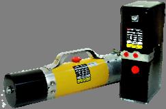
1 HYDRAULIC Compact Power Unit Super Nutech Supply Inc, Copyright Superior Nutech Supply Inc, Copyright Ontario, Canda Ontario, Canada
2 i Content How to Order... Custom Worksheet... Cmmon Application Circuits... ii iii v ypical Central Manifold, Cavities and Valves... 1 Central Manifold... 2 Central Manifold UA. Central Manifold U. Central Manifold UC. Central Manifold UD. Central Manifold UE. Central Manifold US. Central Manifold UX3. Electric Motors DC Motor DC Motor DC Motor.... NEMA AC Motor. IEC AC Motor.. AC Motor Adapter to Central Manifold... Remote Control Handset... Gear Pumps Reservoirs Cartridge Valves Directional Valves Function Symbol Index.. Mounting Style with Manifold A& Mounting Style L with Manifold A& Mounting Style with Manifold C&D Mounting Style L with Manifold C&D ! Warning FAILURE OR IMPROPER SELECION OR IMPROPER USE OF HE PRODUCS AND/OR SYSEMS DESCRIED HEREIN OR RELAED IEMS CAN CAUSE DEAH, PERSONAL INJURY AND PROPERY DAMAGE. his document and other information from Superior Nutech Supply Inc, its subsidiaries and authorized distributors provide product and/or system options for further investigation by users having technical expertise. It is important that you analyze all aspects of your application, including consequences of any failure and review the information concerning the product or system in the current product catalog. Due to the variety of operating conditions and applications for these products or systems, the user, through its own analysis and testing, is solely responsible for making the final selection of the products and systems and assuring that all performance, safety and warning requirements of the application are met. he products described herein, including without limitation, product features, specifications, designs, availability and pricing, are subject to change by Superior Nutech Supply and its subsidiaries at any time without notice. i
3 ii Page 3-18 How o Order Central Manifold Assembly his code include manifold style +circuit code + Option X. Page Electrical Motor -1 : SINGLE ERMINAL -2 : DOULE ERMINAL Power Unit Page Page 31 Resevoir Gear Pump Relief Valve Setting Ordering Code PU UA03X RP3A K21 25 Subplate Mounting Directional Valve Option 3C60 2 P L 1 D Spool ype code Quantity Connection P - Parallel, S Series Mounting Style L - Style L, Style Coil Voltage 0 Same Voltage with motor 1 DC 12V 2 DC 24V 3 AC 110V 4 AC 220V 5 AC 380V Coil Wiring Connector D DIN Same Voltage with motor L Double Lead Wire S Single Lead Wire ii
4 iii Custom Application Worksheet Inquiry Number: Inquiry Date: / / Company: Contact Person: Address: el: Fax: asic Required Information Circuit No. Pressure Port (P): hreaded, size= Others= Return Port (): hreaded, size= Others= Flow Rate = GPM ( LPM) Gear Pump Displacement = ml/rev ( in 3 /rev) Screw-In Solenoid Cartridge Valves Coil Voltage: Coil Style: Single Lead Wire Double Lead Wire Single erminal Double erminal DIN System Relief Valve Setting = PSI ( ar) Second Relief Valve Setting = PSI ( ar) Flow Control Valve Setting = GPM ( LPM) Reservoirs Usable Volume = Gallon ( L) Mounting Hole: hreaded, size= Others= Manifold Directional Control Valves Connection: Series Parallel Mounting Style: L Coil Voltage: Port Size (A1, 1) Remote Control Handset: Yes None DC Electrical Motor AC Electrical Motor Motor Power = kw ype: NEMA IEC Power = KW Voltage: 12V 24V 36V 48V Frame Size = erminal: Single Double Voltage = V Frequency = Hz Starter Relay: Yes None Pole = Fan Cooled: Yes None Phase: Single hree Other Requirements: iii
5 iv Selection Chart Pump, Motor vs. Flow rate and Pressure Nominal Flow Rate (L / GPM) Relief Setting (ar / PSI) Power (kw) Electrical Motor Rated Voltage Model Gear Pump Displacement (ml/r) Actual Flow Rate (L / GPM) REMARK 1.9 / / / / / / / / / / / /24 305A/, 306A/ @ 103ar / 0.50@ 1500PSI 138 / /24 305A/, 306A/ @ 103ar / 0.56@ 1500PSI 172 / /24 308A/ @ 138ar / 0.50@ 2000PSI 207 / /24 308A/ @ 172ar / 0.60@ 2500PSI 103 / /24 305A/ @ 103ar / 0.74@ 1500PSI 138 / /24 308A/ @ 138ar / 0.80@ 2000PSI 172 / /24 308A/ @ 138ar / 0.72@ 2000PSI 207 / /24 312A/ @ 172ar / 0.75@ 2500PSI 103 / /24 308A/ @ 103ar / 1.00@ 1500PSI 138 / /24 308A/ @ 138ar / 0.97@ 2000PSI 172 / /24 312A/ @ 138ar / 0.99@ 2000PSI 207 / /24 416A/ @ 172ar / 1.10@ 2500PSI 103 / /24 308A/ @ 103ar / 1.23@ 1500PSI 138 / /24 312A/ @ 138ar / 1.26@ 2000PSI 172 / /24 312A/ @ 172ar / 1.08@ 2500PSI 207 / /24 416A/ @172ar / 1.10@ 2500PSI 103 / /24 312A/ @ 103ar / 1.44@ 1500PSI 138 / /24 312A/ @ 138ar / 1.35@ 2000PSI 172 / /24 416A/ @ 172ar / 1.44@ 2500PSI 207 / /24 420A/ @ 138ar / 1.40@ 2000PSI 172 / /24 418A/ @ 172ar / 1.60@ 2500PSI 207 / /24 423A/ @ 172ar / 1.56@ 2500PSI 103 / /24 312A/ @ 103ar / 1.84@ 1500PSI 138 / /24 416A/ @ 138ar / 1.80@ 2000PSI 172 / /24 420A/ @ 172ar / 1.79@ 2500PSI 207 / /24 425A/ @ 172ar / 1.78@ 2500PSI 138 / /24 420A/ @ 138ar / 2.10@ 2000PSI 172 / /24 423A/ @ 172ar / 2.00@ 2500PSI 207 / /24 425A/ @ 172ar / 1.90@ 2500PSI 103 / /24 416A/ @ 103ar / 2.20@ 1500PSI 138 / /24 423A/ @ 138ar / 2.37@ 2000PSI 172 / /24 425A/ @ 172ar / 2.17@ 2500PSI 207 / /24 523A/ @ 172ar / 2.20@ 2500PSI 103 / /24 420A/ @ 103ar / 2.78@ 1500PSI 138 / /24 425A/ @ 138ar / 2.67@ 2000PSI 172 / /24 530A/, 531A/ @ 172ar / 2.43@ 2500PSI 207 / /24 533A/, 534A/ @ 172ar / 2.50@ 2500PSI iv
6 v Common Application Circuits Notes: All listed circuits are for typical common application, just part of our solution and products. Superior Nutech will provide designs and products regarding customers requirements and applications v
7 vi Common Application Circuits Notes: All listed circuits are for typical common application, just part of our solution and products. Superior Nutech will provide designs and products regarding customers requirements and applications 17 vi
8 vii Common Application Circuits Notes: All listed circuits are for typical common application, just part of our solution and products. Superior Nutech will provide designs and products regarding customers requirements and applications vii
9 viii Common Application Circuits Notes: All listed circuits are for typical common application, just part of our solution and products. Superior Nutech will provide designs and products regarding customers requirements and applications viii
10 ix Common Application Circuits Notes: All listed circuits are for typical common application, just part of our solution and products. Superior Nutech will provide designs and products regarding customers requirements and applications ix


11 x Superior Hydraulic Power Units are designed specifically for used on Auto hoists,wheel Changers, Semi-electric Pallet ruck, ail gates, Scissor Lifts, ipper trucks, Material handling, Snow plows, Dock levelers, Garbage-Lorry, and many more applications. x
12 xi asic Circuit in Central Manifold 1 = 5 = 2 = 6 = 3 = 7 = 4 = 8 = 1. Please select valve for each cavity from the list below, go to detail pages to locate an model and fill in blank, set up a basic power unit circuit. 2. Valves that listed here are common type, other valves may be available on customer s request, please consult Superior Nutech. We manufacturer cartridge valves for our power unit products. Generally Used Cartridge Valves Symbol Valve ype Detail Page Symbol Valve ype Details Check Valve 36 2-Way, Solenoid Valve, Normally Closed 41 Pilot Check (Load Holding Valve) 37 Check Valve (Manifold Integrated) 44 Directional Valve 43 2-Way Solenoid Valve, Double Locking 39 Relief Valve 43 Manual Valve, Normally Closed 38 Relief Valve (Manifold Integrated) 44 Manual Valve, Double Locking 38 Flow Control Valve, Pressure Compensated 40 Hand Pump 42 Flow Control Valve, Adjustable 41 Plugs 42 Flow Control Valve, Adjustable, Pressure Compensated 40 Flow Control Valve, Adjustable, with Reverse Flow Check 41 xi
13 1 Central Manifold, Valves and Cavities 1
14 2 ype UA (Page 3) he UA central manifold was design for standard duty or heavy duty applications, that using 4.5, 5.0 or AC electrical motor. It shows great flexible on valves configuration to build. Central Manifold Index ype U (Page 8) he U central manifold was designed with integrated check valve and relief valve. It is your economy choice for building a compact power unit. ype UC (Page 13) his manifold was designed specially for applications that need directional valves conform to NFPA D03,CEOP R35H and NG6 mounting interface. It can mount more than one directional valves by applying proper sub plates. ype UD (Page 15) his manifold was designed specially for applications that need directional valves conform to NFPA D03,CEOP R35H and NG6 mounting interface. he different from type UC is the integrated check valve and relief valve. ype UE (Page 17) his manifold was designed with capability of using 4 way 2 position cartridge directional valves, ype US (Page 22) his manifold was designed to work with 3 DC motor for light duty applications. It shows great flexibility on valves configuration to build. ype UX (Page 23) his manifold was designed specially for applications that need bi-rotation, but light duty. It work with 3 DC motor. 2
15 3 Central Manifold UA P P ype UA Central Manifold he ype UA central manifold was design for standard duty or heavy duty applications, that using 4.5, 5.0 or AC electrical motor. It shows great flexibility on valve configuration to build. 130,00 [5,118]" ,00 [3,937] 120,00 [4,724] Material: Aluminum, ,00 [2,165]" 130,00 [5,118]" P 46,40 [1,827]" Applied Electrical Motor: Series DC Motors - 5 Series DC Motors - All AC motors (with adapter applied) Single Acting Applications Double Acting Applications Modular Design Variety circuits and corresponding manifolds design and configurations are available per customers requirements and applications Ports Options: 1. SAE #6 (Standard) 2. NP 3/8 3. G 3/8 4. With Customer Required Valve Cavity:
16 4 Central Manifold vs. ypical Circuit he plugged cavity or ports may not appear on our products if customer doesn t require them. Please add a letter X behind the manifold ordering code if you need the standard central manifold with all cavity and ports formed. For example, A01X. 6 P Applied Manifold... ype UA Check Valve.. N/A Relief Valve... N/A Flow Control Valve.. N/A Ordering Code: - UA00 (Standard, only P and ports formed) - UA00X (with all plugged cavity 1, 2, 3, 4, 5 and 6formed) P Relief Valve Check Valve Applied Manifold... ype UA Check Valve.. CV08R Relief Valve... RVP08 Flow Control Valve.. N/A Ordering Code: - UA01 (Standard) - UA01X (with all plugged cavity 3, 4 and 5 formed) 4
17 5 Central Manifold vs. ypical Circuit he plugged cavity or ports may not be appear on our products if customer didn't require them. Please add a letter X behind the manifold ordering code if you need the standard central manifold with all cavity and ports formed. For example, A01X. Flow Control P Relief Valve Check Valve Applied Manifold... ype UA Check Valve.. CV08R Relief Valve... RVP08 Flow Control Valve.. NV-08 Ordering Code: - UA02 (Standard) - UA02X (with all plugged cavity 3, 4 and 5 formed) Solenoid Valve P 4 5 Relief Valve Check Valve Applied Manifold... ype UA Check Valve.. CV08R Relief Valve... RVP08 Solenoid Valve..SVP08NC Ordering Code: - UA03 (Standard) - UA03X (with plugged cavity 4 and 5 formed) 5
18 6 Central Manifold vs. ypical Circuit he plugged cavity or ports may not be appear on our products if customer doesn t require them. Please add a letter X behind the manifold ordering code if you need the standard central manifold with all cavity and ports formed. For example, A01X. Manual Valve P 4 5 Relief Valve Check Valve Applied Manifold... ype UA Check Valve.. CV08R Relief Valve... RVP08 Manual Valve... MV2L08 Ordering Code: - UA04 (Standard) - UA04X (with all plugged cavity 4 and 5 formed) Manual Valve P 4 Relief Valve Check Valve Applied Manifold... ype UA Check Valve.. CV08R Relief Valve... RVP08 Manual Valve...MV2L08 Flow Control Valve.. NVA-08 Ordering Code: - UA05 (Standard) - UA05X (with plugged cavity 4 formed) 6
19 7 Central Manifold vs. ypical Circuit he plugged cavity or ports may not be appear on our products if customer doesn t require them. Please add a letter X behind the manifold ordering code if you need the standard central manifold with all cavity and ports formed. For example, A01X. P 4 Flow Control Solenoid Valve Relief Valve Check Valve Applied Manifold... ype UA Check Valve.. CV08R Relief Valve... RVP08 Solenoid Valve..SVP08NC Flow Control Valve...NVA08 Ordering Code: - UA04 (Standard) - UA04X (with all plugged cavity 4 formed) Hand Pump Manual Valve P E Relief Valve Check Valve Applied Manifold... ype UA Check Valve..CV08R Relief Valve... RVP08 Manual Valve....MV2L08 Hand Pump... CHP0803 Ordering Code: - UA05 (Standard) - UA05X (with plugged cavity 5 formed) 7
20 8 Central Manifold U P ype U Central Manifold SAE4/6 his Manifold was designed with integrated check valve and relief valve. It is your economic choice for building a compact power unit P 2x3/8-16UNF 100 [3,937"] 130 [5,118"] 46,4 [1,827"] 55 [2,165"] Material: Aluminum Alloy Applied Electrical Motor: Series DC Motors - 5 Series DC Motors - All AC motors (with adapter applied) 120 [4,724"] Single Acting Applications Double Acting Applications Modular Design Variety circuits and corresponding manifolds design and configurations are available per customers requirements and applications Ports Options: 1. SAE #6 (Standard) 2. NP 3/8 3. G 3/8 4. With Customer Required Valve Cavity:
21 9 Central Manifold vs. ypical Circuit he plugged cavity or ports may not be appear on our products if customer doesn t require them. Please add a letter X behind the manifold ordering code if you need the standard central manifold with all cavity and ports formed. For example, A01X. P Relief Valve Integrated Check Valve Integrated Applied Manifold. ype U Check Valve. CVD08 Relief Valve.. RVD08 Ordering Code: - U01 (Standard, Port formed and plugged when shipping) - U01X (with all plugged cavity 3, 4 and 5 formed) Needle Valve P Relief Valve Integrated Check Valve Integrated Applied Manifold..ype U Check Valve.. CVD08 Relief Valve.. RVD08 Needle Valve NV08 Ordering Code: - U02 (Standard) - U02X (with plugged cavity 3, 4 and 5 formed) 9
22 10 Central Manifold vs. ypical Circuit he plugged cavity or ports may not be appear on our products if customer doesn t require them. Please add a letter X behind the manifold ordering code if you need the standard central manifold with all cavity and ports formed. For example, A01X. P 4 5 2/2 Solenoid Valve Relief Valve Integrated Check Valve Integrated Applied Manifold. ype U Check Valve. CVD08 Relief Valve.. RVD08 Solenoid Valve.SVP08NC Ordering Code: - U03 (Standard, Port formed and plugged when shipping) - U03X (with all plugged cavity 4 and 5 formed) P 4 5 Manual Valve Relief Valve Integrated Check Valve Integrated Applied Manifold..ype U Check Valve.. CVD08 Relief Valve.. RVD08 Manual Valve MV2L08 Ordering Code: - U04 (Standard) - U04X (with plugged cavity 4 and 5 formed) 10
23 11 Central Manifold vs. ypical Circuit he plugged cavity or ports may not be appear on our products if customer doesn t require them. Please add a letter X behind the manifold ordering code if you need the standard central manifold with all cavity and ports formed. For example, A01X. P 4 Flow Control Manual Valve Relief Valve Integrated Check Valve Integrated Applied Manifold. ype U Check Valve. CVD08 Relief Valve.. RVD08 Manual Valve.. MV2L08 Ordering Code: - U05 (Standard, Port formed and plugged when shipping) - U05X (with all plugged cavity 4 formed) P 4 Solenoid Valve Flow Control Relief Valve Integrated Check Valve Integrated Applied Manifold..ype U Check Valve.. CVD08 Relief Valve.. RVD08 Solenoid Valve SVP08NC Flow Control Valve.. NVA08 Ordering Code: - U06 (Standard, Port formed and plugged when shipping) - U06X (with plugged cavity 4 formed) 11
24 12 Central Manifold vs. ypical Circuit he plugged cavity or ports may not be appear on our products if customer doesn t require them. Please add a letter X behind the manifold ordering code if you need the standard central manifold with all cavity and ports formed. For example, A01X. Manual Valve Hand Pump P 3 Relief Valve Integrated Check Valve Integrated Applied Manifold. ype U Check Valve. CVD08 Relief Valve.. RVD08 Manual Valve MV2L08 Hand Pump..CHP08 Ordering Code: - U07 (Standard, Port formed and plugged when shipping) - U07X (with all plugged cavity 3 formed) 12
25 13 Central Manifold UC ype UC Central Manifold SAE6 A SAE6 his manifold was designed specifically for applications that need directional valves conforming to NFPA D03,CEOP R35H and NG6 mounting interface. It can mount more than one directional valve by applying proper sub plates. 130MM [5.118"] MM [3.268"]" 120MM [4.724"]" 2x3/8-16UNF 55MM [2.165"] 31MM [1.22"] A P 40,50 [1,594] 130MM [5.118"] 32.5MM [1.28"] 46MM [1.811"] Material: Aluminum Alloy Applied Electrical Motor: Series DC Motors - 5 Series DC Motors - All AC motors (with adapter applied) Double Acting Applications with Directional Valves Modular Design Variety circuits and corresponding manifolds design and configurations are available per customers requirements and applications Ports Options: 1. SAE #6 (Standard) 2. NP 3/8 3. G 3/8 4. With Customer Required Valve Cavity:
26 14 Central Manifold vs. ypical Circuit A Relief Valve Applied Manifold....ype UC CheckValve. CV08R Relief Valve..RVP08 Manual Directional Valve..MC60 Check Valve Ordering Code: - UC12 (Standard, Port A and plugged when shipping) A Relief Valve Check Valve Applied Manifold..ype U Check Valve...CV08R Relief Valve RVP08 Directional Valve...3C60, 3C3, etc. Ordering Code: - UC13 (Standard, Port A and plugged when shipping) 14
27 15 Central Manifold UD ype UD Central Manifold SAE6 A SAE6 his manifold was designed specifically for applications that need directional valves conforming to NFPA D03,CEOP R35H and NG6 mounting interface. he different from type C is the integrated check valve and relief valve. It can be mount more than one directional valves by applying proper sub plates MM [5.118"] 83.0mm [3.268"] 2x3/8-16UNF 55.0MM [2.165"] 31.0mm [1.220"] A 32.5mm [1.280"] 46.0MM [1.811"] Material: Aluminum Alloy P 40.5mm [1.594"] 130.0mm [5.118"] Applied Electrical Motor: Series DC Motors - 5 Series DC Motors - All AC motors (with adapter applied) Double Acting Applications with Directional Valves Modular Design Variety circuits and corresponding manifolds design and configurations are available per customers requirements and applications Ports Options 1. SAE #6 (Standard) 2. NP 3/8 3. G 3/8 4. With Customer Required Valve Mounting Pattern NEPA D03, CEOP D35H, ISO4401 and NG6 15
28 16 Central Manifold vs. ypical Circuit A Relief Valve Integrated Check Valve Integrated Applied Manifold....ype UD Check Valve.CVD08 Relief Valve..RVD08 Manual Directional Valve..MC60 Ordering Code: - UD12 (Standard, Port A and plugged when shipping) A Relief Valve Integrated Check Valve Integrated Applied Manifold..ype UD Check Valve...CVD08 Relief Valve...RVD08 Directional Valve...3C60 Ordering Code: - UD13 (Standard, Port A and plugged when shipping) 16
29 17 Central Manifold UE ype UE Central Manifold his manifold was designed specifically for applications that need directional valves, and preferring screw-in cartridge valve, instead of sandwich valve(d03, NG6 mounting interface). It can mount more than one directional valves by applying proper sub plates. A A C D E F Material: Aluminum Alloy Applied Electrical Motor: Series DC Motors - 5 Series DC Motors - All AC motors (with adapter applied) Double Acting Applications with Directional Valves Modular Design Variety circuits and corresponding manifolds design and configurations are available per customers requirements and applications Ports Options: 1. SAE #6 (Standard) 2. NP 3/8 3. G 3/8 4. With Customer Required Valve Cavity: 08-4, 08-3 and
30 18 Central Manifold vs. ypical Circuit A Applied Manifold....ype UE Check Valve....CVD08 Relief Valve..RVD08 Manual Directional Valve..FSV08E Ordering Code: - UE18 (Standard, Port A and plugged when shipping) A Applied Manifold..ype UE Check Valve..CVD08 Relief Valve...RVD08 Needle Valve...NV08 Directional Valve...FSV08E Ordering Code: - UE19 (Standard, Port A and plugged when shipping) 18
31 19 Central Manifold vs. ypical Circuit A Applied Manifold....ype UE Check Valve.CVD08 Relief Valve..RVD08 Directional Valve SVP08NC.FSV08E Ordering Code: - UE20 (Standard, Port A and plugged when shipping) A Applied Manifold...ype UE Check Valve...CVD08 Relief Valve....RVD08 Needle Valve.NV08 Directional Valve....SVP08NC....FSV08E Ordering Code: - UE21 (Standard, Port A and plugged when shipping) 19
32 20 Central Manifold vs. ypical Circuit A Applied Manifold....ype UE Check Valve....CVD08 Relief Valve.....RVD08 Needle Valve..NV08 Dual Pilot Operated Check Valve...DPV08 Directional Valve...FSV08E Ordering Code: - UE22 (Standard, Port A and plugged when shipping) A Applied Manifold...ype UE Check Valve..CVD08 Relief Valve....RVD08 Dual Pilot Operated Check Valve...DPV08 Directional Valve SVP08NC.FSV08E Ordering Code: - UE23 (Standard, Port A and plugged when shipping) 20
33 21 Central Manifold vs. ypical Circuit A Applied Manifold. ype UE Check Valve....CVD08 Relief Valve.....RVD08 Dual Pilot Operated Check Valve...DPV08 Directional Valve...SVP08NC....FSV08E Ordering Code: - UE24 (Standard, Port A and plugged when shipping) A Applied Manifold.. ype UE Check Valve...CVD08 Relief Valve...RVD08 Needle Valve.NV08 Dual Pilot Operated Check Valve...PVI08NO Directional Valve..SVP08NC...FSV08E Ordering Code: - UE25 (Standard, Port A and plugged when shipping) 21
34 22 Central Manifold US ype US Central Manifold - small size, works with 3 DC motor he central manifold US was designed for lighter duty applications, that using 3 DC electrical motor. It shows great flexibility on valves configuration to build a variety of hydraulic circuit. P Material: - Aluminum Alloy Applied Electrical Motor: - 3 Series DC Motors Single Acting Applications Double Acting Applications Modular Design Variety circuits and corresponding manifolds design and configurations are available per customers requirements and applications Ports Options: 1. SAE #3 (Standard) 2. NP 1/4 3. G 1/4 Valve Cavity:
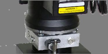
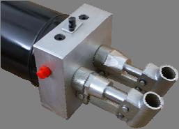
![23 ype UX For i-rotation Applications - mini size, work with 3 DC motor Central Manifold UX Unit: mm [inch] Using this central manifold, we build equivalent power unit with Parker 108 series.](/docs-images/86/94709739/images/35-0.jpg "Material: i-rotation Applications Compact Design - Aluminum, 6061-6 heat treatment. Applied Electrical Motor: - 3 Series DC Motors with i-rotation option.")
35 23 ype UX For i-rotation Applications - mini size, work with 3 DC motor Central Manifold UX Unit: mm [inch] Using this central manifold, we build equivalent power unit with Parker 108 series. Material: i-rotation Applications Compact Design - Aluminum, heat treatment. Applied Electrical Motor: - 3 Series DC Motors with i-rotation option. - Double Acting Applications he UX central manifold was design for i-rotation applications, using 3 DC electrical motor. It equivalent 108 series power unit. 23
36 24 DC Motor 305A -1 Ordering Code Ø3.15 (80mm) Permanent Magnet, ENV Enclosure, i-rotation Ordering Code Rated Power Rated Voltage Rated Current Rated Speed S2 S3 Enclosure Insulation Protection 305A 500W 12V 70A Min 20% ENV Class F IP W 24V 36A Min 20% ENV Class F IP42 Series Wound, ENV Enclosure Electrical Motor -1 : SINGLE ERMINAL -2 : DOULE ERMINAL 306A 500W 12V 70A Min 20% ENV Class F IP W 24V 36A Min 20% ENV Class F IP42 Ø3.81 (97mm) Series Wound, ENV Enclosure Ordering Code Rated Power Rated Voltage Rated Current Rated Speed S2 S3 Enclosure Insulation Protection 308A 800W 12V 112A Min 20% ENV Class F IP W 24V 59A Min 20% ENV Class F IP42 312A 1200W 12V 150A Min 20% ENV Class F IP W 24V 80A Min 20% ENV Class F IP42 Ø80 Ø97 153MAX [6.02 ] 160 [6.3 ] 24
37 25 DC Motor 416A -1 Ordering Code Ø4.5 (112mm) Electrical Motor -1 : SINGLE ERMINAL -2 : DOULE ERMINAL Series Wound, Standard Duty, ENV Enclosure Ordering Code Rated Power Rated Voltage Rated Current Rated Speed S2 S3 Enclosure Insulation Protection 416A 1.6kW 12V 235A Min 20% ENV F IP kW 24V 120A Min 20% ENV F IP44 418A 1.8kw 12V 270A Min 20% ENV F IP44 420A 2.0kW 12V 330A Min 20% ENV F IP kW 24V 140A Min 20% ENV F IP44 425A 2.5KW 12V 380A Min 20% ENV F IP KW 24V 160A Min 20% ENV F IP44 Note: All these motor have starter relay mounted. 25
38 26 DC Motor Ordering Code Ø5 (128mm) Electrical Motor -1 : SINGLE ERMINAL -2 : DOULE ERMINAL Series Wound, Heavy Duty, ENV Ordering Code Rated Power Rated Voltage Rated Current Rated Speed S2 S3 Enclosure Insulation Protection kW 24V 180A Min 20% ENV F IP kW 24V 190A Min 40% ENV F IP44 Note: All these motor have starter relay mounted. Series Wound, Extended Heavy Duty, Fan Cooled. Ordering Code Rated Power Rated Voltage Rated Current Rated Speed S2 S3 Insulation Protection kW 24V 180A Min 20% F IP kW 24V 190A Min 40% F IP44 Note: All these motor have starter relay mounted. 26
 Power (kw) Frame Size Speed Approval C H L M H FR HD FW HW H N05S 0.50 0.37 56C 1725/3450 UL 70 181.26 282 76.2 88.9 167.48 149.")
39 27 AC Motor NEMA AC Motor Steel Housing & Mount With Cooling Fan N05S NEMA AC Motor -2 Ordering Code -2 : 2 Poles, Speed : 4 Poles, Speed 1725 Single Phase Voltage 115/ V Frequency - 60Hz Capacitor Starting, Short-time Duty Motor Code Power (HP) Power (kw) Frame Size Speed Approval C H L M H FR HD FW HW H N05S C 1725/3450 UL N07S C 1725/3450 UL N10S C 1725/3450 UL N15S C 1725/3450 UL N20S C 1725/3450 UL N30S C 1725/3450 UL N40S C 1725/3450 UL hree Phase Voltage /460V Frequency - 60Hz Motor Code Power (HP) Power (kw) Frame Size Speed Approval C H L M H FR HD FW HW H N C 1725/3450 UL N C 1725/3450 UL N C 1725/3450 UL N C 1725/3450 UL N C 1725/3450 UL N C 1725/3450 UL N C 1725/3450 UL
 Power (HP) Speed Approval C H L M H FR FW HD HW E71S 71 0.37 0.50 1400/2800 CE 45 145 255 90 125 105 145 85 112 E72S 71 0.55 0.")
40 28 AC Motor E71S -2 Ordering Code IEC AC Motor Aluminum Housing Capacitor Start, Capacitor Running, Continuous Duty IEC AC Motor -2 : 2 Poles, Speed : 4 Poles, Speed 1400 Single Phase Voltage: 220V, Frequency: 50Hz Motor Code Frame Size Power (kw) Power (HP) Speed Approval C H L M H FR FW HD HW E71S /2800 CE E72S /2800 CE E81S /2800 CE E82S /2800 CE E91S /2800 CE E92S /2800 CE E10S /2800 CE E11S /2800 CE hree Phase Voltage: 380V, Frequency: 50Hz Motor Code Frame Size Power (kw) Power (HP) Speed Approval C H L M H FR FW HD HW E /2800 CE E /2800 CE E /2800 CE E /2800 CE E /2800 CE E /2800 CE E /2800 CE E /2800 CE E /2800 CE 28
41 29 AC Motor Adapter to Central Manifold AC Motor Adapter: DN56, DE07, DE08, DE09,DE10 AC Motor Shaft Coupler: SC56, SC07, SC08, SC09, SE10 NEMA MOOR FRAME SIZE 56C DN56 SC56 IEC MOOR FRAME SIZE 71 DE07 SC07 DE10 IEC MOOR FRAME SIZE 80 DE08 SC08 DE09 IEC MOOR FRAME SIZE 90S/90L DE09 SC09 DE08 IEC MOOR FRAME SIZE 100 DE10 DE07 SC10 29


42 30 Remote Control Handset Part No. uttons Coils Can be Operated Work with C Single Acting Unit KC to 2 Double Acting Unit How to Order NC51 - C - 03 NC Single Acting Unit NC to 2 Double Acting Unit Controller C, w/ Connector X, w/o Connector Length of Lead Wire (in metric) NC to 4 Any Special Units WRC Single Acting Unit WRC to 2 Double Acting Unit WRC to 4 Any Special Unit Wireless Controller WRC Series WR Series WR to 2 Double Acting Unit WR to 4 Any Special Unit Cable Controller KC Series NC Series C Series Wireless Receiver 2 in 1 Wireless Receiver (w/ manual ctrl button) Connector Optional Connector Part No Pins ype Material IP Grade CM-XXX Male Plug Zinc plated Copper IP CW-XXX Female Plug Zinc plated Copper IP65 CM-XXX Male Plug Zinc plated Copper IP CL-XXX Female Socket Zinc plated Copper IP55 C-XXX Male Plug Zinc plated Copper IP L-XXX Female Socket Steel and AS IP55 PM-401 Male Plug AS IP67 4 PW-401 Female Plug AS IP67 PM-401 Male Plug AS IP67 4 PL-401 Female Socket AS IP67 30


 1.1* 1.2 1.3 1.4 1.6 2.1* 2.4* 2.7 3.0* 3.9* 4.2 Rated Pressure: 2500PSI Max.")
43 31 Gear Pumps CQ Pump - Fix Displacement (for Intermittent Light Duty, 3 DC Motor Only) Code Q05 Q06 Q07 Q08 Q09 Displacement (cipr) Displacement (ml/r) 0.5* For bi-rotation model, code CQ will replace the letter Q Rated Pressure: 2000PSI Max. Pressure: 2500PSI Rated Speed: 4000RPM Max Speed: 6000RPM 0.9 CS Pump - Pressure alanced (for Continuous Duty, 3 DC Motor Only) Code S05 Q06 Q07 Q08 Q10 Displacement (cipr) Displacement (ml/r) Rated Pressure: 3000PSI Max. Pressure: 3500PSI Rated Speed: 2000RPM Max Speed: 3000RPM CK Pump - Fix Displacement (for Intermittent Heavy Duty) Code K11 K12 K13 K14 K16 K21 k24 K27 K30 K39 K42 Displacement (cipr) Displacement (ml/r) 1.1* * 2.4* * 3.9* 4.2 Rated Pressure: 2500PSI Max. Pressure: 3000PSI Rated Speed: 4000RPM Max Speed: 6000RPM CG Pump - Pressure alanced (for Continuous Duty) Code Displacement (cipr) Displacement (ml/r) G11 G13 G16 G21 G27 G32 G37 G42 G48 G G G Rated Pressure: 3000PSI Max. Pressure: 3500PSI Rated Speed: 2000RPM Max Speed: 6000RPM 31
44 32 Reservoirs LS ype SEEL Code LS1A() LS2A() LS3A() LS4A() LS5A() LS6A() Usable Volume Dim L Gallon Liter Inch mm MS ype SEEL Code MS1A() MS2A() MS3A() MS4A() MS5A() MS6A() MS7A() MS8A() Usable Quart Volume Liter Dim L Inch mm
45 33 RP ype POLYEHYLENE Reservoirs 173 [6.81 ] 173 [6.81 ] 210 [8.27 ] Code RP0A() RP1A() RP2A() RP3A() RP4A() RP5A() Usable Gallon Volume Liter Inch Dim L mm MR/M ype SEEL Style MR is designed for working with NEMA 56C AC motors. Style M is designed for working with 4.5 DC motors. Usable Volume Dim L Code MR2A() M2A() MR3A() M3A() MR4A() M4A() MR5A() M5A() MR6A() M6A() MR7A() M7A() MR8A() M8A() MR9A() M9A() Gallon Liter Inch 11.02" mm
46 34 HR ype Steel Rectangular Reservoirs Code HR1-A//C HR2-A//C HR3-A//C HR-4A//C HR5-A//C HR6-A//C Usable Volume Dim L Gallon Liter Inch mm
47 35 Cartridge Valves all ype Check Valve Nominal Flow Rate... Max. Operating Pressure... Internal Leakage... Cracking Pressure... emperature... Filtration... Fluid Viscosity... Seals... 2 GPM (7.5L/min) 4500PSI (315ar) 2 to 4 drops/min 4, 15, 30, 40, 50 PSI (0.27, 1.0, 2.0, 3.5 ar) C to 93.3 C (-35 F to 200 F) 30 Micron 36SSU to 3000SSU (3CS to 64CS) O-ring, una Cavity Ordering Code: CV R Poppet ype Check Valve Nominal Flow Rate... Max. Operating Pressure... Internal Leakage... Cracking Pressure... emperature... Filtration... Fluid Viscosity... Seals... Cavity GPM (7.5L/min) 4500PSI (315ar) 2 to 4 drops/min 4, 15, 30, 40, 50 PSI (0.27, 1.0, 2.0, 3.5 ar) C to 93.3 C (-35 F to 200 F) 30 Micron 36SSU to 3000SSU (3CS to 64CS) O-ring, una Ordering Code: CVP R 35
48 36 Cartridge Valves Pilot Operated Check Valve (Load Holding Valve) Nominal Flow Rate... 2 GPM (7.5L/min) Max. Operating Pressure... Internal Leakage... emperature... Filtration... Fluid Viscosity... Seals PSI (315ar) 2 to 4 drops/min C to 93.3 C (-35 F to 200 F) 30 Micron 36SSU to 3000SSU (3CS to 64CS) O-ring, una Cavity Ordering Code: PVI NO Dual Pilot Operated Check Valve (Load Holding Valve) Nominal Flow Rate... Max. Operating Pressure... Internal Leakage... emperature... 2 GPM (7.5L/min) 4500PSI (315ar) 2 to 4 drops/min C to 93.3 C (-35 F to 200 F) Filtration Micron Fluid Viscosity... 36SSU to 3000SSU (3CS to 64CS) Seals... O-ring, una Cavity Order Code: DPV
49 37 Cartridge Valves Manual Directional Valve, Poppet ype (Normally Closed) Nominal Flow Rate... 2 GPM (7.5L/min) Max. Operating Pressure... Internal Leakage... emperature... Filtration... Fluid Viscosity... Seals PSI (315ar) 2 to 4 drops/min C to 93.3 C (-35 F to 200 F) 30 Micron 36SSU to 3000SSU (3CS to 64CS) O-ring, una Cavity Ordering Code: MV2L - 08 Solenoid Valve, Poppet ype (Manual Override) Nominal Flow Rate... 2 GPM (7.5L/min) Max. Operating Pressure PSI (315ar) Internal Leakage... 2 to 4 drops/min emperature C to 93.3 C (-35 F to 200 F) Filtration Micron Fluid Viscosity... 36SSU to 3000SSU (3CS to 64CS) Seals... O-ring, una Cavity Coil ype... DIN Ordering Code: SVP NCM - Voltage D12-12V, DC D24-24V, DC D48-48V, DC A11-110/115V, AC A22-220/230V, AC 37
50 38 Cartridge Valves Solenoid Valve, Poppet ype Normally Closed Nominal Flow Rate... Max. Operating Pressure... Internal Leakage... emperature... Filtration... Fluid Viscosity... Seals... Cavity GPM (7.5L/min) 4500PSI (315ar) 2 to 4 drops/min C to 93.3 C (-35 F to 200 F) 30 Micron 36SSU to 3000SSU (3CS to 64CS) O-ring, una Coil ype... DIN Ordering Code: SVP NC - Voltage D12-12V, DC D24-24V, DC D48-48V, DC A11-110/115V, AC A22-220/230V, AC Solenoid Valve, Poppet ype Double locking Nominal Flow Rate... Max. Operating Pressure... Internal Leakage... emperature... Filtration... Fluid Viscosity... Seals... Cavity GPM (7.5L/min) 4500PSI (315ar) 2 to 4 drops/min C to 93.3 C (-35 F to 200 F) 30 Micron 36SSU to 3000SSU (3CS to 64CS) O-ring, una Coil ype... DIN Ordering Code: SVP Dl - Voltage D12-12V, DC D24-24V, DC D48-48V, DC A11-110/115V, AC A22-220/230V, AC 38
51 39 Cartridge Valves In-line Needle Valve (Pressure Compensated) Nominal Flow Rate... 2 GPM (7.5L/min) Max. Operating Pressure... Internal Leakage... emperature... Filtration... Fluid Viscosity... Seals PSI (315ar) 4 to 5 drops/min C to 93.3 C (-35 F to 200 F) 30 Micron 36SSU to 3000SSU (3CS to 64CS) O-ring, una Cavity... Port 6, G1/4 Ordering Code: NV-08 Shut Off Valves, Adjustable Nominal Flow Rate... Max. Operating Pressure... Internal Leakage... emperature... 2 GPM (7.5L/min) 4500PSI (315ar) 2 to 4 drops/min C to 93.3 C (-35 F to 200 F) Filtration Micron Fluid Viscosity... 36SSU to 3000SSU (3CS to 64CS) Seals... O-ring, una Cavity Ordering Code: NVA
52 40 Cartridge Valves Hand Pump Displacement... Max. Operating Pressure to 4.8ml/rev (0.098 to cipr) 4500PSI (315ar) Internal Leakage... 4 to 5 drops/min emperature C to 93.3 C (-35 F to 200 F) Filtration Micron Fluid Viscosity... 36SSU to 3000SSU (3CS to 64CS) Seals... O-ring, una Cavity Order Code: CHP Displacement Example: 3 3.0ml/rev Flow Control Valves Adjustable, with Reverse Flow Check Nominal Flow Rate... 2 GPM (7.5L/min) Max. Operating Pressure PSI (315ar) Internal Leakage... 4 to 5 drops/min emperature C to 93.3 C (-35 F to 200 F) Filtration Micron Fluid Viscosity... 36SSU to 3000SSU (3CS to 64CS) Seals... O-ring, una Cavity Order Code: NVC
53 41 Cartridge Valves Relief Valve, Pilot Operated Nominal Flow Rate... 2 GPM (7.5L/min) Max. Operating Pressure... Internal Leakage... emperature... Filtration... Fluid Viscosity... Seals PSI (315ar) 4 to 5 drops/min C to 93.3 C (-35 F to 200 F) 30 Micron 36SSU to 3000SSU (3CS to 64CS) O-ring, una Cavity Order Code: RVP - 08 FOUR-WAY,WO-Position, Spool-ype Cartridge Solenoid Valve Nominal Flow Rate... Max. Operating Pressure... Internal Leakage... emperature... Filtration... Fluid Viscosity... Seals... Cavity GPM (7.5L/min) 4500PSI (315ar) 4 to 5 drops/min C to 93.3 C (-35 F to 200 F) 30 Micron 36SSU to 3000SSU (3CS to 64CS) O-ring, una Order Code: FSV E - Voltage D12-12V, DC D24-24V, DC D48-48V, DC A11-110/115V, AC A22-220/230V, AC 41
54 42 Cartridge Valves Relief Valve (Manifold Integrated) Nominal Flow Rate... Max. Operating Pressure... Internal Leakage... Cracking Pressure... emperature... Filtration... Fluid Viscosity... 2 GPM (7.5L/min) 4500PSI (315ar) 2 to 4 drops/min 4, 15, 30, 40, 50 PSI (0.27, 1.0, 2.0, 3.5 ar) C to 93.3 C (-35 F to 200 F) 30 Micron 36SSU to 3000SSU (3CS to 64CS) Seals... O-ring, una Cavity Ordering Code: RVD - 08 Check Valve (Manifold Integrated) Nominal Flow Rate... Max. Operating Pressure... Internal Leakage... Cracking Pressure... 2 GPM (7.5L/min) 4500PSI (315ar) 2 to 4 drops/min 4, 15, 30, 40, 50 PSI (0.27, 1.0, 2.0, 3.5 ar) emperature C to 93.3 C (-35 F to 200 F) Filtration Micron Fluid Viscosity... 36SSU to 3000SSU (3CS to 64CS) Seals... O-ring, una Cavity Ordering Code: CVD
55 43 Cartridge Valves Cavity Plugs CP1(08-2) CP2(08-3) CP3(3/4-16NP) CP4 43
56 44 Directional Valves General Specifications: ype: Mounting Pattern : Spool Valve NFPA D03, Cetop R35H, ISO 4401, NG6 Ambient emp. Operating Pressure: Port P,A, PSI (350ar) Port PSI (210ar) Fluid emp. 41 F -140 F Viscosity: SUS (15-310cst) Filtration: 25 Micron Flow Rate: Up to 42GPM (160L) Coil Voltage: Specified by customer Connector: DIN
57 45 Directional Valves Content Index Applied Central Manifold Style Mounting L Style Mounting Parallel Series Parallel Series ype UA Page 47 Page 47 Page 46 Page 46 ype U Page 47 Page 47 Page 46 Page 46 ype UC Page 49 Page 49 Page 48 Page 48 ype UD Page 49 Page 49 Page 48 Page 48 45
58 46 Directional Valves Central Manifold UA & U Mounting Style Parallel Connection P A P A P A P A P Series Connection A P A P A P 46
59 47 Directional Valves Central Manifold UA & U Mounting Style L Parallel Connection A P A P A P A P Series Connection A P A P A P 47
60 48 Directional Valves Central Manifold UC & UD Mounting Style Parallel Connection C P A P A P Series Connection C P A P A P 48
61 49 Directional Valves Central Manifold UC & UD Mounting Style L Parallel Connection C UP301 UP202 UP204 A P A P A P Series Connection C UP311 UP212 UP213 UP205 A P A P A P 49
62 50 Subplate for Directional Valves UP mm [1.76"] A Unit: mm [inches] 45mm [1.77"] 32.5mm [1.28"] 31mm [1.22"] 37.5mm [1.48"] 56mm [2.20"] UP mm [3.94"] 60mm [2.36"] A P 130mm [5.12"] 46mm [1.81"] UP mm [0.37"] 8.75mm [0.34"] 45mm [1.77"] 32.5mm [1.28"] Unit: mm [inch] 44.5mm [1.75"] 31mm [1.22"] UP mm [3.94"] A A A P 130mm [5.12"] 50mm [1.97"] 50
63 51 Subplate for Directional Valves UP [0.34"] 9.5mm [0.37"] 43.5mm [1.71"] A 46mm [1.81"] 32.5 [1.28"] 31mm [1.22"] 6.25mm [0.25"] 35mm [1.38"] UP202 Unit: 50mm [1.97"] A 50mm [1.97"] 37.5mm [1.48"] 60mm [2.36"] 130mm [5.12"] A P UP [0.34"] 9.5mm [0.37"] 43.5mm [1.71"] A Unit: mm [inch] 46mm [1.81"] 32.5 [1.28"] 31mm [1.22"] 6.25mm [0.25"] 35mm [1.38"] UP204 50mm [1.97"] A 50mm [1.97"] 37.5mm [1.48"] 60mm [2.36"] 130mm [5.12"] A P 51
64 52 Subplate for Directional Valves UP [0.34"] 9.5mm [0.37"] 43.5mm [1.71"] A Unit: mm [inches] 46mm [1.81"] 32.5 [1.28"] 31mm [1.22"] 6.25mm [0.25"] 35mm [1.38"] UP mm [1.97"] A 50mm [1.97"] 37.5mm [1.48"] 60mm [2.36"] 130mm [5.12"] A P UP mm [0.37"] 43.5mm [1.71"] Unit: mm [inch] 46mm [1.81"] 8.75 [0.34"] 32.5 [1.28"] 31mm [1.22"] A 6.25mm [0.25"] 35mm [1.38"] UP mm [1.97"] A 50mm [1.97"] 37.5mm [1.48"] 60mm [2.36"] 130mm [5.12"] A P 52
65 53 Subplate for Directional Valves UP221 Unit: mm [inches] 7.25mm [0.29"] 37.5mm [1.48"] 35mm [1.38"] 60mm [2.36"] UP221 50mm [1.97"] 130mm [5.12"] P 50mm [1.97"] UP mm [0.25"] Unit: mm [inch] 7.5mm [0.3"] 37.5mm [1.48"] UP mm 12mm[1.97"] 60mm [0.47"] [2.36"] 75mm [2.95"] 53
66 54 Subplate for Directional Valves UP mm [0.68"] 31mm [1.22"] 32.5mm [1.28"] 37.5mm [1.48"] Unit: mm [inches] C201 UP mm [3.94"] A 60mm [2.36"] 55.5mm [2.19"] A P 46mm [1.81"] 75mm [2.95"] UP311 Unit: mm [inch] 17.25mm [0.68"] 31mm [1.22"] 32.5mm [1.28"] 37.5mm [1.48"] 311 UP mm [3.94"] A 55.5mm [2.19"] 60mm [2.36"] A P 46mm [1.81"] 75mm [2.95"] 54
67 55 Subplate for Directional Valves UP mm [1.28"] 37.5mm [1.48"] Unit: mm [inches] 17.25mm [0.68"] 31mm [1.22"] 60mm [2.36"] C221 UP321 60mm [2.36"] 46mm [1.81"] 75mm [2.95"] P 55

68 Superior Nutech Supply Inc. specializes in producing high quality and competitively priced hydraulic components for many markets such as: Construction, road equipment, cranes, lifts, dock levelers, scissor lifts, forestry and logging equipment, Mining, highway transportation, Railway, waste equipment, industrial machines and many more. SUPERIOR brand name equals HIGH QUALIY. Whether you require a standard catalogue item or our engineering team to specially design and manufacture a product to your suit your application, you can count on Superior. With our manufacturing capabilities and partnerships we can provide a wide range of quality products such as: Welded Cylinders, AG tie rod cylinder, Snow Plow Cylinders, Compact power packs, Cartridge valves, Gear Head Office, sales and manufacturing: 142 Sugar Maple Rd St. George, Ontario, Canada N0E N0 Phone: Fax: Manufacturing: 879 Zhongjiang Rd, uilding 27 Shanghai, China
Sandwich Valves Series CP
 Technical Information General Description. pilot operated check valves are designed for maximum flow rates. The valves are typically used in combination with spool type directional control valves to ensure
Hydraulics 1. Directional Control Valves Series D1M. Features. Application. Operation. D1MW Solenoid Operated Free Lead Wire
 ulletin 2544-1/US Introduction pplication arker D1M Series hydraulic directional control valves are high performance, direct operated 4-way valves. hey are available in 2 or 3 position styles. hey are
Compact power pack program RE 00163/ The Drive & Control Company
 Compact power pack program RE 00163/08.06 he Drive & Control Company Bosch Rexroth Oil Control Compact power pack program Compact power pack modular system Compact power packs are available with standard
DOUBLE, P.O. CHECK VALVES (PRE-ENGINEERED BLOCKS)
") DOUBLE, P.O. CHECK VALVES (PRE-ENGINEERED BLOCKS) SERIES DOUBLE PILOT OPERATED CHECK VALVE... HS3 Page HD1 Page HD2 SERIES DOUBLE PILOT OPERATED CHECK VALVE GPM PSI LPM BAR CAVITY MODEL PAGE 5 3500 19
DOUBLE, P.O. CHECK VALVES (PRE-ENGINEERED BLOCKS) SERIES DOUBLE PILOT OPERATED CHECK VALVE... HS3 Page HD1 Page HD2 SERIES DOUBLE PILOT OPERATED CHECK VALVE GPM PSI LPM BAR CAVITY MODEL PAGE 5 3500 19
POWER UNITS CATALOG INNOVATIVE MOBILE SOLUTIONS
 POWER UNITS CATALOG INNOVATIVE MOBILE SOLUTIONS ABOUT US INNOVATIVE MOBILE SOLUTIONS OUR CAPABILITIES Eagle Hydraulic Inc. is a Canadian based manufacturer of engineered and standard hydraulic cylinders.
Solenoid Valves. Poppet and Spool type solenoid actuated valves for applications up to 350 bar (5000 psi) and 227 L/min (60 USgpm) A-1.
 and 227 L/min (60 USgpm) A-1.") Solenoid Valves Poppet and Spool type solenoid actuated valves for applications up to 5 bar (5 psi) and 7 L/min (6 USgpm) n Eaton Brand ETON Screw-In Cartridge Valves E-VLSC-MC-E November 9 -. Solenoid
Solenoid Valves Poppet and Spool type solenoid actuated valves for applications up to 5 bar (5 psi) and 7 L/min (6 USgpm) n Eaton Brand ETON Screw-In Cartridge Valves E-VLSC-MC-E November 9 -. Solenoid
HY-SPEC CATALOGUE - HYDRAULIC VALVES. Hydraulic Valves. Visit our website Catalogue
 HY-SPEC CATALOGUE - HYDRAULIC VALVES Hydraulic Valves Catalogue Visit our website HY-SPEC PRODUCT FAMILY HY-SPEC CATALOGUE - AC/DC POWER PACKS HY-SPEC CATALOGUE - GAS ENGINE PRODUCTS Accessories AC/DC
Monarch D.C. Hydraulic Power Systems. Comprehensive information may be found on the page referenced below each selection category.
 Monarch D.C. Hydraulic Power Systems MODEL M-319 Description: Pump/Motor/Reservoir/Valve Check Valve 2-Way/2-Position Normally Closed Solenoid Operated Lowering Valve Externally Adjustable Relief Valve
Industrial Hydraulic Valves. Directional Control, Pressure Control, Sandwich, Subplates & Manifolds, Accessories. Catalog HY /US
 Industrial Hydraulic Valves irectional Control, Pressure Control, Sandwich, Subplates & Manifolds, Accessories Catalog HY14-25/US Industrial Hydraulic Valves WARNING USER RESPONSIBILITY FAILURE OR IMPROPER
Pilot Operated Pressure Relief Valve Series R5V (Denison)
") Characteristics Pilot operated pressure relief valves series R5V have a similar design to the subplate mounted R4V series. The SAE flanges allow to mount the valves directly on the outlet flanges of pumps
Characteristics Pilot operated pressure relief valves series R5V have a similar design to the subplate mounted R4V series. The SAE flanges allow to mount the valves directly on the outlet flanges of pumps
Hydraulic Pump VP1-120
 REECHSROY GROUP REECHNOLOGY Bulgaria, Varna 9000 Industrial Zone Str. Studentska 1 U/UK1 odernization, complex repair and maintenance of heavy industrial equipment. Infrastructure construction and management
Proportional Valves. Proportional solenoid valves for pressure and flow control
 Proportional Valves Proportional solenoid valves for pressure and flow control EATON Vickers Screw-In Cartridge Valves V-VLOV-MC-E4 September, 7 - Electro- Proportional Valves Section Contents Typical
Proportional Valves. Proportional solenoid valves for pressure and flow control B-1.A. An Eaton Brand
 Proportional Valves Proportional solenoid valves for pressure and flow control An Eaton rand -.A Proportional Valves Valve Locator/Section Contents Note: Proportional valve solenoid coils and electronic
Directional Control Valves
 Overview HYDAC offers several functions of the Directional Control Cartridges. HYDAC Manually operated position, - way normally closed, spring return, directional valve features poppet design. It offers
Hydraulic Screw-in Cartridge Valves (SiCV) Proportional valves Proportional solenoid valves for pressure and flow control
 Proportional valves Proportional solenoid valves for pressure and flow control") Hydraulic Screw-in Cartridge Valves (SiCV) Proportional valves Proportional solenoid valves for pressure and flow control Proportional valves PROPORTIONAL VALVES... - PFRH... -8 EPV...- EPV6...- EPV6A...-7
Hydraulic Screw-in Cartridge Valves (SiCV) Proportional valves Proportional solenoid valves for pressure and flow control Proportional valves PROPORTIONAL VALVES... - PFRH... -8 EPV...- EPV6...- EPV6A...-7
Chapter 5: Flow Valves
 Catalogue HY11-300/UK Contents Chapter : Flow Valves Series Description Size Mounting Page Parker Standard DIN / ISO 1/4 3/8 1/2 3/4 1 06 10 16 Throttle valves, manual adjustment MVI -2 NS -4 FS With free
Large Electronically Adjustable Proportional Pressure Compensated Flow Control Engineering & Manufacturing Solutions
 Engineering & Manufacturing Solutions LEFC Specifications: See flow chart for capacity. Max. 3000 psi cartridge input pressure. Nominally Rated for 3000 psi (207 bar). Tank Port - #4 SAE (10 psi (0.69
BW0511FP. ByWire Elements BW0511FP Flow Sharing Element Interface IBW0511
 ywire Elements Flow Sharing Element Interface IW05 efore use, carefully read the GENERL INSTRUCTIONS FOR USE OF DIRECTIONL CONTROL VLVES Technical data Nominal flow Nominal pressure 35 l/min - P=8 bar
Pressure Compensator Valves Series R5P (SAE Flange Mounted) General Description. Features
 General Description. Features") Technical Information General Description Series R5P direct operated, 3-way pressure compensators can be combined with any type of fixed or adjustable flow resistor (throttle) to provide a load compensated
Technical Information General Description Series R5P direct operated, 3-way pressure compensators can be combined with any type of fixed or adjustable flow resistor (throttle) to provide a load compensated
USA Headquarters. Dynex/Rivett Inc. 770 Capitol Drive Pewaukee, WI U.S.A. Tel: FAX:
 SPECIFICAIONS D05 Pattern Directional Control Valves Also refer to "Directional Valve Features, Selection and Operating Recommendations" (dynexdcvoperating.pdf) CONAC INFORMAION USA Headquarters Dynex/Rivett
Gear Pumps / Motors. Series PGP / PGM Fixed Displacement Pumps, Cast-Iron and Aluminium Designs
 Gear Pumps / Motors Series PGP / PGM Fixed Displacement Pumps, Cast-Iron and Aluminium Designs Table of contents Heavy-duty Pumps and Motors Series PGP, PGM Contents Page Series 500 Aluminium Table of
Chapter 6: Check Valves
 Contents Chapter : Check Valves Series Description Size Mounting Page Parker Standard DIN / ISO 1/8 1/4 3/8 1/2 3/4 1 0 10 1 25 32 Subplate Screw-in Slip-in Shuttle valves SSR -2 Check valves, direct operated
DRV2-080 Adjustable, Direct-Acting Relief Valve
 SOLENOID DRV2-080 Adjustable, Direct-Acting Relief Valve SERIES 8 CHECK MOTION FLOW USASI / ISO ➁ ➀ DESCRIPTION An adjustable, direct-acting poppet cartridge valve designed to limit pressure in hydraulic
Available manual, pneumatic, and hydraulic spool control kits.
 Fitted with a main pressure relief valve and a load check valve on every working section. Available with parallel circuit. Optional carry-over Variety of port valves (auxiliary valves) Available manual,
D05 Directional Control Valves
 Engineering D05 Directional Control Valves WFDG4S*4-01, 60 Design Wet Armature Solenoid Operated Max Pressure up to 248 Bar (3600 psi) Same Day Shipments www.fluidynefp.com Table of Contents Basic Characteristicts...2
Solenoid valves. Poppet and Spool type solenoid actuated valves for applications up to 350 bar (5000 psi) and 227 L/min (60 USgpm)
 and 227 L/min (60 USgpm)") Hydraulic Screw-in Cartridge Valves (SiCV) Solenoid valves Poppet and Spool type solenoid actuated valves for applications up to 5 bar (5 psi) and 7 L/min (6 USgpm) Solenoid valves SOLENOID VLVES...- SV5-8-C/CM
Hydraulic Screw-in Cartridge Valves (SiCV) Solenoid valves Poppet and Spool type solenoid actuated valves for applications up to 5 bar (5 psi) and 7 L/min (6 USgpm) Solenoid valves SOLENOID VLVES...- SV5-8-C/CM
HEC2003/2004 Series Servo Valve System
 BULLETIN 10006 Bul. 5.00 GUIDING SYSTEMS October 2011 HEC2003/2004 Series Servo Valve System High response servo valve with spool position feedback signal All components are mounted over the drip pan Servo
Logic elements. Differential pressure sensing elements for applications up to 350 bar (5000 psi) and 400 L/min (100 USgpm)
 and 400 L/min (100 USgpm)") Hydraulic Screw-in Cartridge Valves (SiCV) Logic elements Differential pressure sensing elements for applications up to 50 bar (5000 psi) and 400 L/min (00 USgpm) Logic elements LOGC ELEMENTS... -4 APPLCATON
Hydraulic Screw-in Cartridge Valves (SiCV) Logic elements Differential pressure sensing elements for applications up to 50 bar (5000 psi) and 400 L/min (00 USgpm) Logic elements LOGC ELEMENTS... -4 APPLCATON
CVH103P. Check Valve Series CVH103P. Technical Information. General Description
 Catalog HY-351/US Information Cartridge Style Valve. For additional information see Tips on pages 1-4. Valve Series H13P Spherical poppet for low leakage D -Ring eliminates back-up rings Dual sense paths
Hydraulic Motor/Pump. Series F11/F12 Fixed Displacement
 Hydraulic Motor/Pump Series F11/F12 Fixed Displacement Series F11/F12 Torque (M) M = D x p x η hm 63 [Nm] Conversion factors 1 kg... 2.20 lb 1 N... 0.225 lbf 1 Nm... 0.738 lbf ft 1 bar...14.5 psi 1 l...0.264
Hydraulic Power Packs
 Hydraulic Power Packs Hydraulic Pump / Hydraulic Valve / Hydraulic Accessory ISO 9001:2008/ISO 14001:2004 283 Danforth Avenue, Suite 348, Toronto, ON Canada M4K 1N2 www.lprglobal.com / www.uskoreahotlink.com
Chapter 6: Check Valves
 Contents Chapter : Check Valves Series Description Size Mounting Page Parker Standard DIN / ISO 1/8 1/4 3/8 1/2 3/4 1 0 10 1 25 32 Subplate Screw-in Slip-in SSR RK / RB CS SPZBE SPV / SPZ C4V CPS C4V D4S
Pressure Control Valves. General Description. Specifications. Ordering Information
 Catalog HY14-3000/US Technical Information Control Valves Series RCP General escription Series RCP in-line pressure control valves are chiefly used as remote control valves. They limit system pressure
Type of operation Depending on requirement either one or two dry DC-solenoid,
 Features Leakage free High availability 100% duty cycle Porting NG 6 according to DIN 24340 Positive overlap Function and design The seated valves are direct operated. Depending on the desired control
Post-Compensated Proportional Valve CV2000LS
 www.nimco-controls.com Post-Compensated Proportional Valve CV2000LS Smart Solutions... for the Future Contents Page 5 Page 6 Page 7 Page 8 Page 9 Page 10 Page 11 Page 12 Page 13 Page 14 Page 15 Page 16
Colorflow and Ball Valves. Industrial Flow Control, Check, Gauge Control. Catalog HY /US
 Colorflow and Industrial Flow Control, Check, Gauge Control Catalog HY14-3300/US Colorflow and Fully guided poppets are used on Colorflow valves rather than the less durable ball-check type construction.
VALVES RANGE FOR OPEN LOOPS T E C H N I C A L C A T A L O G
 VALVES RANGE FOR OPEN LOOPS T E C H N I C A L C A T A L O G Valves range for open loop 2 18/07/2017 Valves range for open loop CONTENT CHECK VALVES 5 Direct operated valves 7 Pilot operated valves 11 Counterbalance
KE-M02 configuration Configuratie documentatie documentation KE-M02
 Configuratie documentatie KE-M02 1/32 2/32 3/32 4/32 5/32 General Technical Data for Compact Power Module KE series Through the years DCOC has developed a highly evolved modular system resulting in powerful,
Gear Pumps / Motors. Series PGP / PGM Fixed Displacement Pumps, Cast-Iron and Aluminium Designs
 Gear Pumps / Motors Series PGP / PGM Fixed Displacement Pumps, Cast-Iron and Aluminium Designs Contents Contents Page PGP/PGM500 Characteristics... 3 PGP502 Ordering... 4 PGP502 Performance curves... 5
VED*M PROPORTIONAL PILOT OPERATED DIRECTIONAL CONTROL VALVES
 CONTINENTAL HYDRAULICS VED*M PROPORTIONAL PILOT OPERATED DIRECTIONAL CONTROL VALVES 5505 WEST 123RD STREET SAVAGE, MN 55378-1299 / PH: 952.895.6400 / WWW.CONTINENTALHYDRAULICS.COM TOUGH VED*M PROPORTIONAL
EFC. Electronically Adjustable Proportional Pressure Compensated Flow Control
 Engineering & Manufacturing Solutions Specifications: See flow chart for capacity. 3000 psi (207 bar) rating. Weighs 8-1/2 lbs. (3.9 kg). Standard Port size #12SAE (1-1/16 12). 10-Micron Filtration Recommended.
RPE3-04. Functional Description HA /2010. Directional Control Valves Solenoid Operated. Replaces HA /2007
 Directional Control Valves Solenoid Operated RPE3-04 Size 04 (D 02) 320 bar (4600 PSI) 30 L/min (8.0 GPM) 10/2010 Replaces 12/2007 4/3-, 4/2- way directional control valves with solenoid control Solenoids
D03 FluiDyne Valves. ENGINEERING DATA
 ENGINEERING D D3 FluiDyne Valves 4 Way, and 3 Postion Solenoid Operated Variety of Voltage and Spool Configurations Same Day Shipments 1 Month Warranty www.fluidynefp.com D3 FluiDyne Valves: 4 Way, and
Directional Control Valve Series D1VW
 Characteristics The NG6 directional control valve series D1VW provides high functional limits up to 8 l/min in combination with a very low, energy-saving pressure drop. A wide variety of spool options
High Pressure Gear Pumps & Motors Series PZG Pumps Series MZG Motors
 High Pressure Gear Pumps & Motors Series PZG Pumps Series MZG Motors Bulletin 650-Z1 High Pressure Gear Pumps and Gear Motors for today s demanding mobile and industrial applications. The PZG and MZG Series
Directional Control Valve Series 4D01 (DENISON)
") Characteristics The Denison series 4D01 is a solenoid operated directional control valve size NG06 in -chamber design. It is direct operated by wet pin solenoids. The 4D01 is available with a Soft Shift
Characteristics The Denison series 4D01 is a solenoid operated directional control valve size NG06 in -chamber design. It is direct operated by wet pin solenoids. The 4D01 is available with a Soft Shift
Hydraulic Motor/Pump. Series F11/F12 Fixed Displacement. parker.com/pmde
 Hydraulic Motor/Pump Series F11/F12 Fixed Displacement parker.com/pmde Series F11/F12 Torque (M) M = D x p x η hm 63 [Nm] Conversion factors 1 kg... 2.20 lb 1 N... 0.225 lbf 1 Nm... 0.738 lbf ft 1 bar...14.5
Chapter 2: Directional Control Valves
 Contents Chapter : Directional Control Valves Series Description Direct operated Pilot operated Page DIN / ISO 06 10 16 5 3 10 16 5 3 Seat valves, electrically operated D1SE - Spool valves, electrically
p max (see table of performances) Q max (see table of performances) bar Maximum flow rate from port P to A - B - T l/min
 Q max (see table of performances) bar Maximum flow rate from port P to A - B - T l/min") 41 400/117 ED E*P4 PILOT OPERATED DISTRIBUTOR SOLENOID OR HYDRAULIC (C*P4) CONTROLLED E4P4 CETOP P05 E4R4 ISO 4401-05 E5 ISO 4401-08 p max (see table of performances) Q max (see table of performances)
41 400/117 ED E*P4 PILOT OPERATED DISTRIBUTOR SOLENOID OR HYDRAULIC (C*P4) CONTROLLED E4P4 CETOP P05 E4R4 ISO 4401-05 E5 ISO 4401-08 p max (see table of performances) Q max (see table of performances)
REVERSIBLE HYDRAULIC POWER PACKS. 1 node/142/
 REVERSIBLE HYDRAULIC POWER PACKS 1 node/142/ 2 Introduction Oil Sistem is a leader in power packs production and offers a wide range of solutions suitable for every type of application. Oil Sistem developed
74 Series ISO Interchange
 Series ISO 8 Interchange Featuring Snap-tite quality with superior pressure and flow characteristics over the competition. Flush Face/Dry Break design facilitates easy cleaning prior to connection High
Service Manual Series F12
 Bulletin HY30-5504-M1/UK Effective: June, 2006 Supersedes: August, 2003 List of contents Page General information...3 Specifications...4 Disassembling...5-10 Assembling...11-16 Change of shaft seal...17
HYDRAULIC MOTORS HP APPLICATION GENERAL. » Conveyors» Feeding mechanism of robots and manipulators» Metal working machines» Textile machines
 HYDRAULIC HP APPLICAION» Conveyors» Feeding mechanism of robots and manipulators» Metal working machines» extile machines» Agricultural machines» Food industries» Grass cutting machinery etc. CONENS Specification
RPE3-04. Functional Description HA /2013. Directional Control Valves Solenoid Operated. Replaces HA /2010
 Directional Control Valves Solenoid Operated RPE3-04 Size 04 (D 02) 320 bar (4600 PSI) 30 L/min (8.0 GPM) HA 4014 09/2013 Replaces HA 4014 10/2010 4/3-, 4/2- way directional control valves with solenoid
RNEH4-25. Functional Description HA / /2 and 4/3 Way Directional Control Valves Pilot Operated. Replaces HA /2012
 4/2 and 4/3 Way Directional Control Valves Pilot Operated RNEH4-25 HA 4024 7/2015 Size 25 (D 08) 320 bar (4600 PSI) 600 L/min (159 GPM) Replaces HA 4024 6/2012 Solenoid pilot operated directional valves
ISO Interchange SERIES
 ISO 18 Interchange SERIES Series ISO 18 Interchange Featuring Snap-tite quality with superior pressure and flow characteristics over the competition. Flush Face/Dry Break design facilitates easy cleaning
Hydraulic Motor/Pump. Series F11/F12 Fixed Displacement. parker.com/pmde
 Hydraulic Motor/Pump Series F11/F12 Fixed Displacement parker.com/pmde Series F11/F12 Torque (M) M = D x p x η hm 63 [Nm] Conversion factors 1 kg... 2.20 lb 1 N... 0.225 lbf 1 Nm... 0.738 lbf ft 1 bar...14.5
Pilot Operated Directional Control Valves Series D1VP, D3DP, D4P, D9P, D11P
 Characteristics Series D1VP, D3DP, D4P, D9P, D11P The D1VP is a hydraulically controlled 4/3 or 4/ way directional control valve. The valve can be operated either by the pilot ports X and Y via the subplate
ANTI-SHOCK DIRECTIONAL CONTROL VALVES
 ACTUATED, DIRECT OPERATED TYPICAL PERFORMANCE SPECIFICATIONS Performance is measured on a four-way circuit (full circuit). Performance may e reduced from that shown if a three-way circuit (half circuit)
Check Valves (C Series) Catalog 4130-C Revised, July 2004
 Catalog 4130-C Revised, July 2004") Check Valves (C Series) Catalog 4130-C Revised, July 2004 Introduction Parker C Series Check Valves are designed for uni-directional flow control of fluids and gases in industries such as chemical processing,
Check Valves (C Series) Catalog 4130-C Revised, July 2004 Introduction Parker C Series Check Valves are designed for uni-directional flow control of fluids and gases in industries such as chemical processing,
Vickers Pressure Relief Solenoid Operated, Two-Stage Directional Control Valve DG5S4-02 Flows to 115 l/min (30 USgpm) Pressure to 210 bar (3000 psi)
 Pressure to 210 bar (3000 psi)") Vickers Pressure Relief Solenoid Operated, Two-Stage Directional Control Valve DG5S4-02 Flows to 115 l/min (30 USgpm) Pressure to 210 bar (3000 psi) Revised 2/93 GB C 2037 Table of Contents Model Code...................................................................................................
Vickers Pressure Relief Solenoid Operated, Two-Stage Directional Control Valve DG5S4-02 Flows to 115 l/min (30 USgpm) Pressure to 210 bar (3000 psi) Revised 2/93 GB C 2037 Table of Contents Model Code...................................................................................................
Super Charged Piston Pumps Variable Displacement For Open Circuits. PAVC Medium Pressure
 aerospace climate control electromechanical filtration fluid & gas handling hydraulics pneumatics process control sealing & shielding PAVC Medium Pressure Super Charged Piston Pumps Variable Displacement
Pilot Operated Directional Control Valves Series D31DW, D31NW, D*1VW
 Characteristics The pilot operated valves are available in 4 sizes: D31DW NG10 (standard) D31NW NG10 (high flow) D41VW NG16 D81VW NG5 (for port diameter up to 6 mm) D91VW NG5 (for port diameter up to 3
DMH085** Series will be available January 1, Catalog HY /US SERIES CAVITY DESCRIPTION FLOW PRESSURE PAGE NO.
 Catalog HY-/US Contents SERIES CAVITY DESCRIPTION FLOW PRESSURE PAGE NO. /GPM BAR/PSI DL8... C8-... Position, Way, N.C. Poppet,... Pull to Open.../8... /... DL... C-... Position, Way, N.C. Poppet,... Pull
Pneumatic Valves Viking Lite Series. G1/8 - G3/8 body ported
 aerospace climate control electromechanical filtration fluid & gas handling hydraulics pneumatics process control sealing & shielding Pneumatic Valves Series G1/8 - G3/8 body ported Catalogue May 2015
Ports. Dr. Breit GmbH Carl-Zeiss-Straße 25 D Heiligenhaus phone-contact:
 Solenoid operated EEx d IIC T6 Description of the Valve Directional control valves direct the flow in various directions (P A with 2/2 valves and P A // A T) with 3/2 valves. Available as 2/2 and 3/2 valves,
36EFC. Series & EFC Valve Package
 Engineering & Manufacturing Solutions Specifications: Rated for 0-24 gpm (0-91 lpm) depending on Series 36-38 work sections used. Pressure rating 3000 psi (207 bar). 10 Micron filtration recommended. See
Check valves Direct and pilot operated check valve functions for applications up to 350 bar (5000 psi) and 227 L/min (60 USgpm)
 and 227 L/min (60 USgpm)") Hydraulic Screw-in Cartridge Valves (SiCV) Check valves Direct and pilot operated check valve functions for applications up to 5 bar (5 psi) and 7 L/min (6 USgpm) Check valves CHECK VALVES... -4 FPR -
Hydraulic Screw-in Cartridge Valves (SiCV) Check valves Direct and pilot operated check valve functions for applications up to 5 bar (5 psi) and 7 L/min (6 USgpm) Check valves CHECK VALVES... -4 FPR -
Chapter 10: Valves for Pipe Mounting
 Contents Chapter : Valves for Pipe Mounting Series Description Size Body Page DIN / ISO 1/8 1/4 3/8 1/2 3/4 1 1¼ 1½ 2 L-port T-port Pressure valves, manual operation R4V R4R Pressure relief function Pressure
Parker Fluid Control Angle Body Valves
 Parker Fluid Control Angle Body Valves Angle Body Valve Key Features RED Position indicator on all models Housing is 304 SS standard, or optional Aluminum Piston ring FKM Brass Piston Pilot port available
Directional Control Valves Series D111VW. General Description. Features. Performance Curves
 Technical Information General valves are piloted by a D1VW valve. The valves can be ordered with position control. The minimum pilot pressure must be ensured for all operating conditions of the directional
Subplates (AP) and multi-station subplates
 and multi-station subplates") Subplates and multi-station subplates Type AP700/RP700/ EP700 to 25 l/min Features Subplates (AP) and multi-station subplates (RP) with threaded connections End plate (EP) Compact design up to six stations
Subplates and multi-station subplates Type AP700/RP700/ EP700 to 25 l/min Features Subplates (AP) and multi-station subplates (RP) with threaded connections End plate (EP) Compact design up to six stations
Manapak Sandwich Valves. General Description
 echnical Information Series RM General Description RM Series relief valves limit system pressure by opening to tank when system pressure reaches the valve setting. With D3 size, they can also be configured
Catalog HY /US SERIES CAVITY DESCRIPTION FLOW PRESSURE PAGE NO. LPM/GPM BAR/PSI
 Catalog HY15-352/US Contents SERIES CAVITY DESCRIPTION FLOW PRESSURE PAGE NO. LPM/GPM BAR/PSI PRESSURE RELIEVING AP1B2YP... 2G... Increase /Increase Current...5.3/1.4... 35/5... 7-8 AP2B2YP... C8-2...
Directional Control Valves Series D81V. General Description. Operation. Features. Specifications
 echnical Information General Description W directional control valves are 5-chamber, pilot operated, solenoid controlled valves. hey are available in 2 or 3-position styles. hese valves are manifold or
Directional Seat Valve Series D4S (Denison)
") Characteristics Seat valves series D4S are designed for directional control functions. A large variety of poppets, springs and covers - including shuttle valves, stroke limiters, solenoid valves (VV01)
Characteristics Seat valves series D4S are designed for directional control functions. A large variety of poppets, springs and covers - including shuttle valves, stroke limiters, solenoid valves (VV01)
Pilot-Operated Directional Control Valves Series D3 - D11
 Catalogue HY11-500/UK Characteristics The D31, D41, D81, D91 and D111 are electrical controlled 4/3 or 4/ way directional control valves. The valves are pilot-operated by an NG6 valve. Pressure and flow
Directional Control Valves. General Description. Operation. Features
 echnical Information General Description W directional control valves are 5-chamber, pilot operated, solenoid controlled valves, hey are available in 2 or 3-position styles. hese valves are manifold or
Directional Control Valve Series D3W Soft Shift
 Characteristics The D3W is a 3-chamber, electrically controlled 4/3 or 4/ way directional control valve. It is activated directly by solenoids with screwed in wet pin armature. The soft shifting of this
MINI POWER PACKS WITH SUBMERSED MOTOR AND PUMP
 MINI POWER PACKS WITH SUBMERSED MOTOR AND PUMP CMI Summary table Essential characteristic of the control unit compact CMI is the arrangement of the motor pump unit completely immersed in the oil inside
Directional Control Valves. General Description. Features. Specifications
 Technical Information General Description directional control valves are high-performance, 4-chamber, direct operated, wet armature, solenoid controlled, 3 or 4-way valves. They are available in 2 or 3-position
SR1A-A2. Functional Description HA /2012. Directly Operated Pressure Relief Valves. Replaces HA /2010. Screw-in cartridge design
 Directly Operated Pressure Relief Valves SRA-A2 HA 5063 7/202 3/4-6 UNF p max 350 bar (5080 PSI) Q max 30 L/min (7.9 GPM) Replaces HA 5063 8/200 Screw-in cartridge design 4 pressure ranges Pressure setting
2011 AC & DC Hydraulic. Power Packs Compact. Rotation Ø 15 6,45 3,5 5,7
 Ø 15 6,45 5,7 3,5 11 9 ±. C & DC Hydraulic Rotation ower acks Compact OWER CKS COMCT series ordering code C11/1-1 QUICK SELECTION GUIDE C & DC electric motors DC motors,15 1DC_T 1VDC motor - 15W - Ø 8
Sectional Directional Control Valve RS 220
 Sectional Directional Control Valve RS 0 RS 0 is a sectional open center valve designed for max. operating pressures up to 00 bar and max. pump flows up to 0 l/min. Technical data Pressure and flow values*
Heavy Duty Hydrostatic Transmissions
 Heavy Duty Hydrostatic Transmissions Features and Benefits Typical Applications Construction Transit Mixer Road Roller Paver Motor Grader Loader Dozer Material Handling & Utility Crane Sweeper Lift Truck
Flow Control Valves Check Valves Gauge Control Valves. Colorflow Valves
 Check Valves Gauge Control Valves Colorflow Valves Colorflow and Ball Valves Industrial Flow Control, Check, Gauge Control Catalog HY14-3300/US Colorflow and Ball Valves Fully guided poppets are used on
VSD*S -MONITORED DIRECTIONAL CONTROL VALVES
 CONTINENTAL HYDRAULICS VSD*S MONITORED DIRECTIONAL CONTROL VALVES 5505 WEST 123RD STREET SAVAGE, MN 55378-1299 / PH: 952.895.6400 / WWW.CONTINENTALHYDRAULICS.COM VSD*S MONITORED DIRECTIONAL CONTROL VALVES
Proportional Directional Control Cartridge Valves: PSV10-34 & PSV12-34
 Control Cartridge Valves: PSV10-34 & PSV12-34 SCHEMATIC PRESSURE* FLOW CAVITY COIL Page 2 PSV10-34-02 250 BAR 3600 PSI 22 LPM 6 GPM SDC10-4 M16-26W R16-20W Page 4 PSV12-34-02 260 BAR 3770 PSI 50 LPM 13
Mobile Valves Proportional - Load Sensing
 Mobile Valves Proportional - Load Sensing Model CML60 325 bar 60 L/min Up to 8 sections Eaton F(x) Compliant Table of Contents General Information... 3 Model Code Valve Section... 4 Valve Assembly... 5
P.C. Priority Flow Control Valve Series J02D3. General Description
 CV Catalog HY15-352/US General Description Needle Type, Compensated Regulator Valve. For additional information see Tips on pages 1-4. P.C. Priority Control Valve Series J2D3 Features Good adjustment from
Pneutronics. Miniature Proportional Valves. Catalog PND-MPV-001/US January 2007
 Pneutronics Miniature Proportional Valves January 2007 Non-Thermally Compensated Proportional Valve HF 200 Miniature Ultra High Flow Proportional Valve HF 200 is a high flow proportional valve that provides
ZRV. Direct Operated Check Valve Series ZRV (Denison)
") Characteristics / Ordering Code Direct Operated Check Valve Series ZRV (Denison) Direct operated check valves series ZRV have a cartridge type insert to provide zero leakage and high life time. he check
Characteristics / Ordering Code Direct Operated Check Valve Series ZRV (Denison) Direct operated check valves series ZRV have a cartridge type insert to provide zero leakage and high life time. he check
Hydraulic Power Units D, H, V-Pak and V-Pak Low Profile Series
 aerospace climate control electromechanical filtration fluid & gas handling hydraulics pneumatics process control sealing & shielding Hydraulic ower Units D, H, V-ak and V-ak Low rofile Series HY28-2661-CD/US
Throttle Check Valve Series FM
 Characteristics Double-throttle check valves from the Parker Manapak series FM are in sandwich design for easy configuration of stack systems. Throttle and check valves are located in ports A and B. FM2
PowrFlow PVX Vane Pumps
 PowrFlow PVX Vane Pumps POWRFLOW PVX VANE PUMPS YOUR SOURCE FOR VANE PUMPS FOR THE MOST DEMANDING APPLICATIONS What Makes PowrFlow PVX Vane Pumps Your Best Buy? Continental Hydraulics PowrFlow PVX Vane
SD2E-A3. Functional Description. 3/2 Way Solenoid Operated Directional Control Valves Spool Type HA /2013. Replaces HA /2012
 3/2 Way Solenoid Operated Directional Control Valves Spool Type SD2E-A3 3/4-6 UNF p max 350 bar (5076 PSI) Q max 30 L/min (7.9 GPM) HA 404 /203 Replaces HA 404 07/202 Hardened and precision working parts
NG6. Proportional adjustment. Manifold mounting acc. to ISO External drain. Main stage spool type valve. Pilot stage seated type valve.
 Catalog HY14-255/US Technical Information Series VY*K General Description Series VY*K pilot operated sequence valves feature proportional adjustment and an external drain. The external drain allows application
INSTALLATION DIMENSIONS
 ACCESSORIES & OTHERS PRESURE GAGE INSTALLATION DIMENSIONS UNIT mm(inch) LM TYPE CBM TYPE CBM-F TYPE MODEL B B1 D D1 D2 G H T d R G40LM 28.1(0.86) φ48(1.9) φ41.7(1.6) 8(0.31) 58.7(2.31) 1/8" G40CBM 26(1.02)
Directional Control Valve
 Characteristics The NG6 directional control valve series D1VW provides high functional limits up to 8 l/min in combination with a very low, energy-saving pressure drop. wide variety of spool options allows
CONTENT Axial Piston Motors and Pumps Fixed Displacement. Technical Specification Guide...2. Hydraulic motor MAP Hydraulic motor MAP50...
 CONTENT CONTENT Aial Piston Motors and Pumps Fied Displacement PAGE Technical Specification Guide...2 Hydraulic motor...6 Hydraulic motor MAP5...1 Hydraulic motor MAP1...2 MAP5 Hydraulic pump PAP5...29