KE-M02 configuration Configuratie documentatie documentation KE-M02
|
|
|
- Laura Jackson
- 5 years ago
- Views:
Transcription
1 Configuratie documentatie KE-M02 1/32
2 2/32
3 3/32
4 4/32
5 5/32
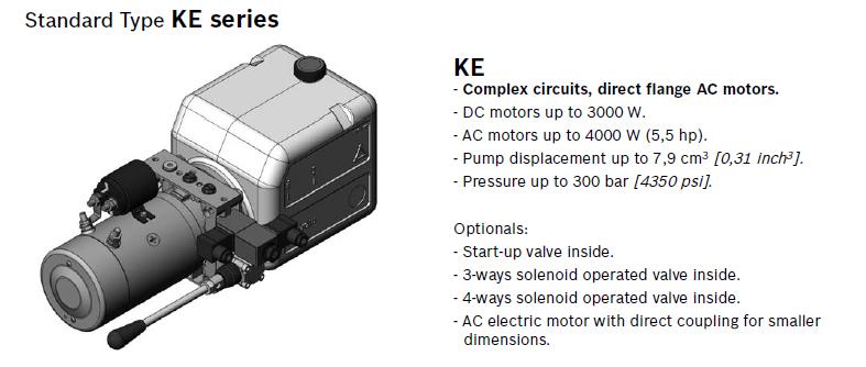
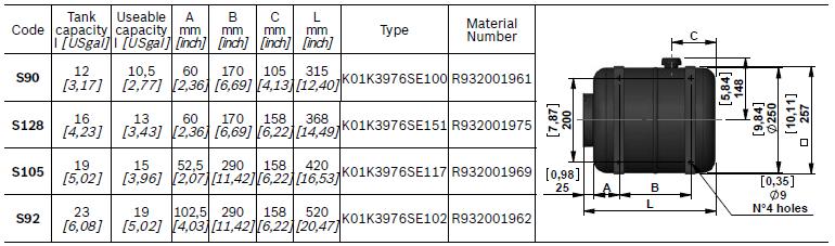
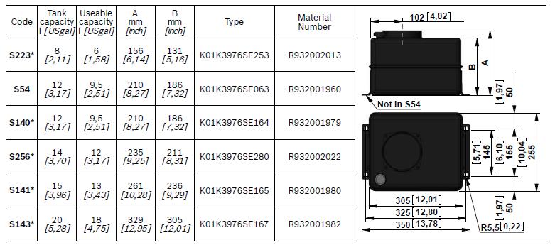
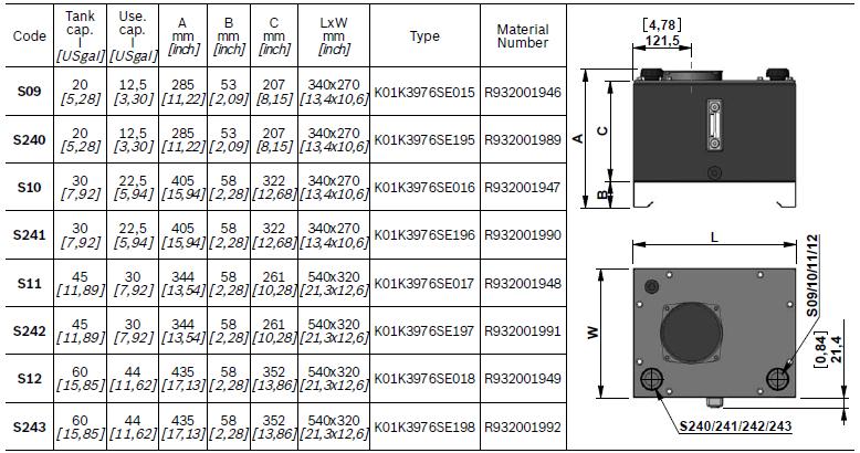
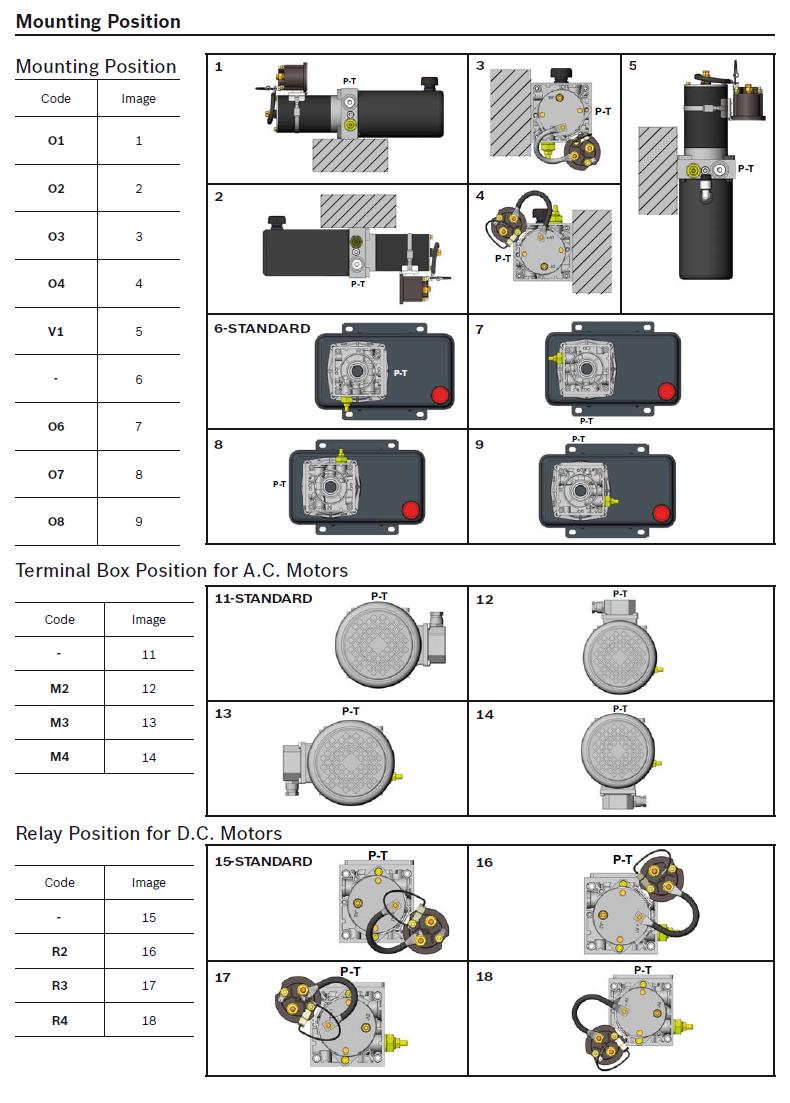
6 General Technical Data for Compact Power Module KE series Through the years DCOC has developed a highly evolved modular system resulting in powerful, flexible and cost effective power pack range, identified as "compact power modules". In its easier configuration, a "compact power module is an assembly of electric motor, central manifold with valves, pump, oil tank and a few connection elements. The central manifold, with its built-in valves, allows to achieve a large variety of hydraulic control circuits. If more complex circuits are needed, modular integrated blocks can be added by flange mounting, or interfacing, to the central manifold to extend its capabilities. Typical applications Passenger lift Fork lift Car and motorcycle lift Table lift Dumper Tail gate Scissor lift Tyre changer Home lift Gangway and davits for boats Power module selection Choose the circuit which meets your application requirements. Take note of all dimensions resulting from the basic components chosen for your application. NOTE: dimensions may vary slightly and should be confirmed by DCOC, if the assembly is to be installed in a space with narrow clearance. The tank capacity and the tank dimensions need to be large enough to assure proper pump suction: there must always be a reserve of oil in the tank when all cylinders are fully extended and avoid overflow when cylinders are fully retracted. The tank must be evaluated also for best separation of air from oil, and for settling down oil contamination. It should be placed in a space with, at least, natural ventilation and it should permit enough heat dissipation to prevent high fluid temperature. Select the electric motor by evaluating the power needed and the motor compliance with the heat developed during the expected run time (or "duty cycle"). Hydraulic fluid for compact power module Mineral oil based hydraulic fluids suitable for hydraulic systems can be used; they should have physical lubricating and chemical properties as specified by: - MINERAL OIL BASED HYDRAULIC FLUIDS HL (DIN part 1) - MINERAL OIL BASED HYDRAULIC FLUIDS HL P(DIN part 2) For use of environmentally friendly fluids please consult DCOC. Fluid viscosity, Temperature range of the operating fluid, Ambient temperature The fluid viscosity should remain within the range 10 to 300 cst (centistokes); recommended 15 to 120 cst. Permissive cold start viscosity is maximum 2000 cst. The fluid temperature should remain within the range -15 C and 80 C [5 F and 176 F]. Note: For compact power module with plastic tank the fluid temperature should remain within the range -15 C and 70 C [5 F and 158 F]. Ambient temperature -15 C +40 C [5 F and 104 F]. Fluid cleanliness requirements and maintenance We recommend a cleanliness of the operating fluid according to ISO 4406 Class 19/17/14 or cleaner. All components of the hydraulic circuit, including hoses and actuators, must be flushed and cleaned before assembling, because the compact power module has a suction filter only. The hydraulic fluid should be replaced after the first 50 hours, and then every 1000 hours, or, at least, once a year. Power module installation The mounting position (is basically un-restricted; just avoid installations that could compromise the pump suction, it is recommended to support the power module on vibration dampening blocks when the mounting structure is expected to vibrate. 6/32
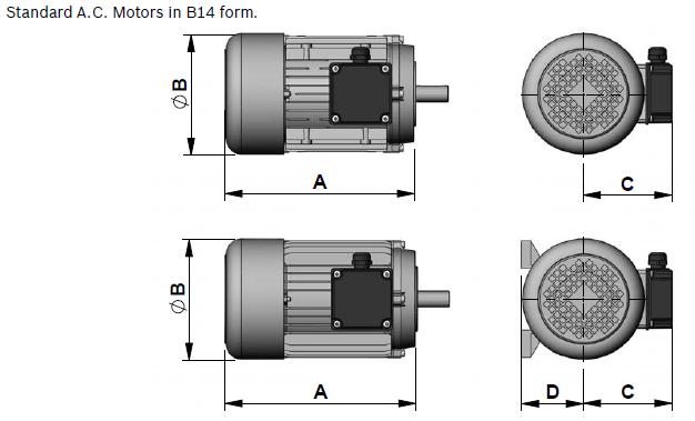
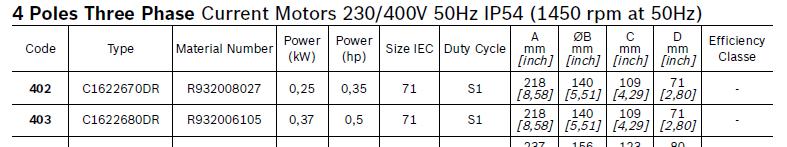
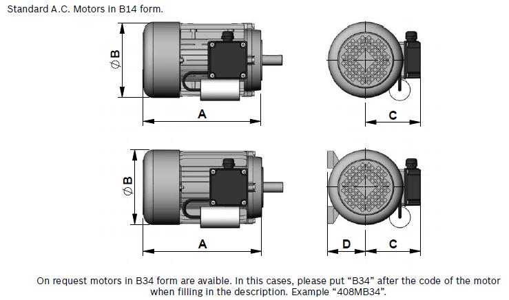
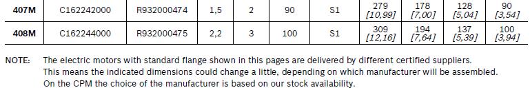
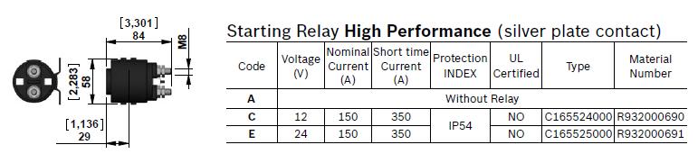
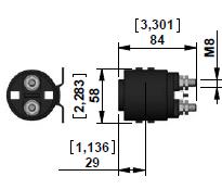
7 General Technical Data for Compact Power Module KE series Wiring and starting-up The wiring between battery and electric motor should be selected in order to avoid excessive voltage drop (recommended less than 1 V). It is strictly forbidden to allow the backwards rotation of the pump even at the first starting: to prevent reverse rotation, the wiring polarities must be correctly connected. Caution: when energized, the surface temperature of the electric motor could reach temperature levels of C [ F]: care should be taken to avoid any accidental contact of people with the motor surface. A.C. Motors The tolerances on the nominal voltage are: Single phase motor: 230V +/-5% - Three phase motor: V +/-10%. Protection degree : IP54 (protection against dust and water splash). Insulation class: F (155 C) [311 F]. All motors are aluminum alloy die cast without painting. Note: standard Single phase motors have a permanently connected run capacitor. If the motor starts with pressure in the circuit (load in the actuator) we suggest the use of specials dedicated manifolds KE series with integrated Start-Up valve (Manifold code M09 and M19). D.C. Motors DCOC has a wide range of D.C. motors. In the following pages you will find a selection of our standard range. For further information about our complete range please contact our Sales department. All the motors shown have clockwise rotation suitable for driving our counter clockwise gear pumps. For each motor a diagram is shown that enables the customer to select the right pump displacement needed for the required flow and working pressure. To be sure of selecting the best electric motor for the application, also the duty cycle has to be verified. Following are the definitions of the type of duty cycles: S2 = Short time duty cycle: indicate the number of minutes the motor can operate before reaching the maximum allowable temperature. After this time the motor must cool down until the ambient temperature is reached. S3 = Intermittent duty cycle: indicate the maximum time percentage (%) based on 10 minute period within the motor can run until reaching the maximum allowable temperature. For example an S3 value of 15% = 1,5 minutes running time every 10 minutes period. For 8,5 minutes the motor is switched-off. The S2 and S3 values are related to the current draw. On the label of motor are indicated the S2 and S3 values referred to the nominal power of the motor. To check the S2 or S3 value at different conditions is necessary to find the value of current in the motor-pumps diagram and related it with the represented list. All the diagrams motor-pumps are obtained at the nominal voltage of 12 or 24 Volt using fluid ISO VG 46 at C [68-86 F]. Central Manifolds All the Central Manifolds shown in the catalogue are made in die cast aluminium alloy. The validation of the Central Manifolds follows a life-test with 250 bar [625 psi] pulsed pressure repeated for cycles. Built-in valves A wide range of cartridge valves and special plugs is available to be assembled in our Central Manifolds. The cartridge valves shown are designed for use in our Compact Power Module and are manufactured using steel with high mechanical strength. Surface treatments protect the exposed parts to the external environment. Standard seals are NBR (BUNA-N) with backup rings in PTFE. The cartridge valves with leak proof seat design have an average leakage of drops/minute (< 1 cm3/minute 0.06 in3/min.) at the maximum pressure using fluid ISO VG46 at 40 C [104 F]. The validation of the cartridge valves follows a life-test at pulsed maximum pressure (indicated for each valve) repeated for cycles. All the solenoid cartridge valves are fitted with protective O-Rings installed between the pole tube and the coil. These O-Rings protect the internal parts from condensation and contaminants, which could cause malfunction. All the solenoid cartridge valves series are designed for operating in D.C.. Power supply in A.C. requires a connector with bridge rectifier included. All the data in the solenoid cartridge valves data sheet are obtained with stabilized coil operating temperature and voltage at -10% of the nominal value. 7/32
8 General Technical Data for Compact Power Module KE series External Gear Pumps DCOC offers a wide range of External Gear Pumps to cover different kinds of applications. The standard versions are suitable for the biggest part of applications. For applications requiring higher peaks of pressure (for example Fork Lift and Presses) a version with cast iron covers is available. For applications requiring high numbers of Start&Stop or low noise feature the tapered shaft version for elastic coupling is preferred (available only for central manifold K series with A.C. motors). All the pumps are pressure compensated to guarantee the best efficiency. Oil Tanks In this catalogue you will find a wide selection of steel and plastic tanks available as a standard product. If a special tank is required please contact our Sales Department. Steel tanks have Black paint finish and are suitable for operating temperature range -15 C / +80 C (5 F / 176 F). Plastic tanks are obtained in one piece in order to avoid welded parts that are weak points at extreme temperature and vibrations. Plastic tanks are suitable for operating temperature range -15 C / +70 C (5 F / 158 F). Note: even if the plastic tank mounting system is designed to avoid oil leakage the tank must be securely anchored when fitted in mobile equipment and when subject to shocks and heavy vibrations. Please check that the anchorages do not stress or deform the tank. Modular Stackable Elements Our modular system offers a wide range of standardised elements. They are divided in two main series: Modular Elements N series: Modular blocks for different mounting position with mechanical valve or interface for CETOP valves to create parallel or series circuits. Modular Elements V series: Modular blocks that incorporate solenoid operated cartridge valves 2,3,4 way. All the Modular Elements are made in extruded aluminum alloy AL 2011 (AlCu5.5Pb0.4Bi0.4 UNI 9002/5). In the catalogue you will find a selection of the main used models. Note: To reduce the complexity of the system and optimize the available space, special Modular Elements can be designed and manufactured following the customers needs. In this case please contact our Sales Department. European machine directive 2006/42/CE According to the Machine Directive2006/42/CE, a complete power module, as described in paragraph 15 and made available to the European market, enters into the definition of "partly completed machinery". Instead, the power module sub-assemblies (motor, pump, reservoir, central manifold,...), when not assembled into a complete power pack, are considered "components" which can be employed in a "machinery" or a "partly completed machinery". In this case, the DCOC components and sub-assemblies must be fitted in compliance with all the relevant technical data sheet applicable to the product, and shall not be operated, adjusted or disassembled before the complete machinery where they are incorporated has been declared to be in compliance with the Machine Directive 2006/42/CE. Note: All the components shown in the catalogue ARE NOT suitable for use in potentially explosive atmosphere. Technical information Below you will find the most common equations used in hydraulics: 8/32
9 9/32
10 10/32
11 11/32
12 12/32
13 13/32
14 14/32
15 15/32
16 16/32
17 EC / EE EA / EAM TPU 17/32
18 18/32
19 EC EE EA6 EA6M EC / EE EA6 / EA6M 19/32
20 EC & EA6 EE EA6M 20/32


21 COIL D36 - CLASS H - 20 W OD X - Y - Z 21/32
22 22/32
23 23/32
24 24/32
25 25/32
26 26/32
27 27/32
28 28/32
29 29/32
30 30/32
31 31/32
32 32/32
Compact power modules KE, K and KS series
 Compact power modules KE, K and KS series RE 18306-02 Edition: 02.2016 Replaces: 12.2014 Contents Ordering Details 2 General echnical Data 6 Compact ower odule ype 9.C. Electric otors 10 D.C. Electric
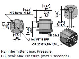
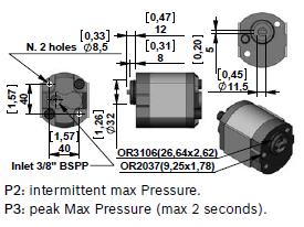
p max (see table of performances) Q max (see table of performances) bar Maximum flow rate from port P to A - B - T l/min
 Q max (see table of performances) bar Maximum flow rate from port P to A - B - T l/min") 41 400/117 ED E*P4 PILOT OPERATED DISTRIBUTOR SOLENOID OR HYDRAULIC (C*P4) CONTROLLED E4P4 CETOP P05 E4R4 ISO 4401-05 E5 ISO 4401-08 p max (see table of performances) Q max (see table of performances)
41 400/117 ED E*P4 PILOT OPERATED DISTRIBUTOR SOLENOID OR HYDRAULIC (C*P4) CONTROLLED E4P4 CETOP P05 E4R4 ISO 4401-05 E5 ISO 4401-08 p max (see table of performances) Q max (see table of performances)
Technical data for Compact Directional valves
 RE 18350-49/04.15 1/8 Technical data for Compact Directional valves Introduction: Following technical data refers to Compact Hydraulics valves (RE 90010-06 chapters 2,3,4 and 5) 1. General Bosch Rexroth
DL /118 ED SOLENOID OPERATED DIRECTIONAL CONTROL VALVE COMPACT VERSION SUBPLATE MOUNTING ISO p max 280 bar Q max 50 l/min
 41 211/118 ED DL3 SOLENOID OPERATED DIRECTIONAL CONTROL VALVE COMPACT VERSION SUBPLATE MOUNTING ISO 4401-03 p max 280 bar Q max 50 l/min MOUNTING SURFACE OPERATING PRINCIPLE ISO 4401-03-02-0-05 (CETOP
p max (see table of performances) Q max (see table of performances) bar Maximum flow l/min see par
 Q max (see table of performances) bar Maximum flow l/min see par") 41 510/112 ED EXPLOSION-PROOF VERSION SOLENOID OPERATED DIRECTIONAL CONTROL VALVES in compliance with ATEX 94/9/EC MD1K ISO 4401-03 (CETOP 03) E4P4K CETOP P05 E07P4K ISO 4401-07 (CETOP 07) E5P4K ISO 4401-08
41 510/112 ED EXPLOSION-PROOF VERSION SOLENOID OPERATED DIRECTIONAL CONTROL VALVES in compliance with ATEX 94/9/EC MD1K ISO 4401-03 (CETOP 03) E4P4K CETOP P05 E07P4K ISO 4401-07 (CETOP 07) E5P4K ISO 4401-08
Directional Control Valve Series 4D01 (DENISON)
") Characteristics The Denison series 4D01 is a solenoid operated directional control valve size NG06 in -chamber design. It is direct operated by wet pin solenoids. The 4D01 is available with a Soft Shift
Characteristics The Denison series 4D01 is a solenoid operated directional control valve size NG06 in -chamber design. It is direct operated by wet pin solenoids. The 4D01 is available with a Soft Shift
4/3, 4/2 proportional directional valves solenoid operated (for open loop control)
") /, / proportional directional valves solenoid operated (for open loop control) RE -/7. Replaces: RE7/.7 / Type L (LCP) Size Series Maximum operating pressure bar [ psi] Nominal flow rated l/min [.7 gpm]
/, / proportional directional valves solenoid operated (for open loop control) RE -/7. Replaces: RE7/.7 / Type L (LCP) Size Series Maximum operating pressure bar [ psi] Nominal flow rated l/min [.7 gpm]
DL /116 ED SOLENOID OPERATED DIRECTIONAL CONTROL VALVE COMPACT VERSION SERIES 10 SUBPLATE MOUNTING ISO p max 320 bar Q max 125 l/min
 41 330/116 ED SOLENOID OPERATED DIRECTIONAL CONTROL VALVE COMPACT VERSION SUBPLATE MOUNTING ISO 4401-05 p max 320 bar Q max 125 l/min MOUNTING INTERFACE OPERATING PRINCIPLE ISO 4401-05-04-0-05 (CETOP 4.2-4-05-320)
DSE3B /118 ED DIRECTIONAL VALVE WITH PROPORTIONAL CONTROL SERIES 10 SUBPLATE MOUNTING ISO p max 350 bar Q max 40 l/min
 83 215/118 ED DSE3B DIRECTIONAL VALVE WITH PROPORTIONAL CONTROL SUBPLATE MOUNTING ISO 4401-03 p max 350 bar Q max 40 l/min MOUNTING INTERFACE OPERATING PRINCIPLE ISO 4401-03-02-0-05 (CETOP 4.2-4-03-350)
4/3-4/2 Proportional directional valves L5080 solenoid (LC04P) operated (for open loop control) L5080 (LC04P)
 operated (for open loop control) L5080 (LC04P)") / - / Proportional directional valves L solenoid (LCP) operated (for open loop control) L (LCP) RE - Edition:. Replaces: 7. 7. Size Series Maximum operating pressure bar ( psi) Maximum flow l/min (.7 gpm)
/ - / Proportional directional valves L solenoid (LCP) operated (for open loop control) L (LCP) RE - Edition:. Replaces: 7. 7. Size Series Maximum operating pressure bar ( psi) Maximum flow l/min (.7 gpm)
4/3-4/2 Directional valve with solenoid actuation
 4/3-4/2 Directional valve with solenoid actuation RE 18305-08/12.13 1/10 L5110 LC1-Z ) Size NG6 ISO 4401-03 CETOP RP121 H-03 CETOP 3) Series 00 Maximum operating pressure 350 bar [5076 psi] Maximum flow
4/3 4/2 Directional valve elements with or without secondary relief valves, and with or without LS connections
 RA 183-52/1.11 1/1 4/3 4/2 Directional valve elements with or without secondary relief valves, and with or without LS connections B8_8 (EDBZ) Summary Description Page General specifications 1 Ordering
Directional Control Valve Series D1VW
 Characteristics The NG6 directional control valve series D1VW provides high functional limits up to 8 l/min in combination with a very low, energy-saving pressure drop. A wide variety of spool options
DSE /117 ED DIRECTIONAL VALVE WITH PROPORTIONAL CONTROL SERIES 11 SUBPLATE MOUNTING ISO p max 350 bar Q max 40 l/min
 83 2/117 ED DSE3 DIRECTIONAL VALVE WITH PROPORTIONAL CONTROL SUBPLATE MOUNTING ISO 41-3 p max 3 bar Q max l/min MOUNTING SURFACE OPERATING PRINCIPLE ISO 41-3-2-- (CETOP 4.2-4-3-3). 33 3.2 21. 12.7.1.7
6 to14/2 ways/positions bankable flow diverters flangeable
 Electric Drives and Controls Hydraulics Linear Motion and Assembly Technologies Pneumatics Service 6 to14/2 ways/positions bankable flow diverters flangeable RE 18302-09/12.09 1/10 L732... (VS241F-VS245F-VS246F-VS247F)
Q max 300 l/min. Fluid temperature range C Fluid viscosity range cst Recommended viscosity cst 25
 41 420/103 ED DSP7 PILOT OPERATED DISTRIBUTOR SOLENOID OR HYDRAULIC(DSC7) CONTROLLED SERIES 10 CETOP 07 p max (see performance ratings table) Q max 300 l/min MOUNTING INTERFACE CETOP 4.2-4-07-320 The DSP7
Q max (see specifications table)
") 41 260/103 ED SOLENOID OPERATED DIRECTIONAL CONTROL VALVES EXPLOSION-PROOF VERSION EEx-dIIC SERIES 20 MD1K CETOP 03 E4P4K CETOP P05 E07P4K CETOP 07 E5P4K CETOP 08 E10P4K CETOP 10 p max (see specifications
41 260/103 ED SOLENOID OPERATED DIRECTIONAL CONTROL VALVES EXPLOSION-PROOF VERSION EEx-dIIC SERIES 20 MD1K CETOP 03 E4P4K CETOP P05 E07P4K CETOP 07 E5P4K CETOP 08 E10P4K CETOP 10 p max (see specifications
Directional valve elements L808103P (ED4-PT1) of Tank unloaded excess flow. RE Edition: Replaces:
 of Tank unloaded excess flow. RE Edition: Replaces:") Directional valve elements L80810P with proportional (ED4-PT1) control of Tank unloaded excess flow L80810P (ED4-PT1) RE 1801-1 Edition: 09.2016 Replaces: 07.12 01.2016 Size 6 Series 00 Maximum operating
Directional valve elements L80810P with proportional (ED4-PT1) control of Tank unloaded excess flow L80810P (ED4-PT1) RE 1801-1 Edition: 09.2016 Replaces: 07.12 01.2016 Size 6 Series 00 Maximum operating
4/3 and 4/2 Proportional directional valve elements L8580 with flow (EDC-P) sharing control (LUDV concept) PATENT PENDING
 sharing control (LUDV concept) PATENT PENDING") / and / Proportional directional valve elements L88 with flow (EDC-P) sharing control (LUDV concept) PATENT PENDING L88 (EDC-P) RE 181-9 Edition:.16 Replaces: 7.1 7.1 Size 6 Series Maximum operating pressure
/ and / Proportional directional valve elements L88 with flow (EDC-P) sharing control (LUDV concept) PATENT PENDING L88 (EDC-P) RE 181-9 Edition:.16 Replaces: 7.1 7.1 Size 6 Series Maximum operating pressure
4/3 and 4/2 on-off directional valve elements L8511 with flow (EDC-DZ) sharing control (LUDV concept) L8511 (EDC-DZ)
 sharing control (LUDV concept) L8511 (EDC-DZ)") 4/3 and 4/2 on-off directional valve elements L8511 with flow (EDC-DZ) sharing control (LUDV concept) L8511 (EDC-DZ) RE 1831-11 Edition: 6.218 Replaces: 7.12 2.216 Size 6 Series Maximum operating pressure
4/3 and 4/2 on-off directional valve elements L8511 with flow (EDC-DZ) sharing control (LUDV concept) L8511 (EDC-DZ) RE 1831-11 Edition: 6.218 Replaces: 7.12 2.216 Size 6 Series Maximum operating pressure
Chapter 2: Directional Control Valves
 Contents Chapter : Directional Control Valves Series Description Direct operated Pilot operated Page DIN / ISO 06 10 16 5 3 10 16 5 3 Seat valves, electrically operated D1SE - Spool valves, electrically
Directional Control Valve Series D3W (Parker), 4D02 (Denison)
, 4D02 (Denison)") Characteristics Series D3W (Parker), 4D0 (Denison) The direct operated directional control valve size NG10 is available with both Parker (series D3W) and Denison (series 4D0) model codes. Both series are
Characteristics Series D3W (Parker), 4D0 (Denison) The direct operated directional control valve size NG10 is available with both Parker (series D3W) and Denison (series 4D0) model codes. Both series are
4/3 and 4/2 Proportional directional valve elements L8581 with flow (EDC-P1) sharing control (LUDV concept) PATENT PENDING
 sharing control (LUDV concept) PATENT PENDING") 4/3 and 4/2 Proportional directional valve elements L881 with flow (EDC-P1) sharing control (LUDV concept) PATENT PENDING L881 (EDC-P1) RE 1831-1 Edition: 6.218 Replaces: 7.12.217 Size 6 Series Maximum
4/3 and 4/2 Proportional directional valve elements L881 with flow (EDC-P1) sharing control (LUDV concept) PATENT PENDING L881 (EDC-P1) RE 1831-1 Edition: 6.218 Replaces: 7.12.217 Size 6 Series Maximum
LOGIC ELEMENTS SERIES 10 LC* LP* /103 ED CARTRIDGE VALVES ISO DIN COVERS FOR CARTRIDGE VALVES ND
 48 900/103 ED LC* LP* LOGIC ELEMENTS CARTRIDGE VALVES ISO 7368 - DIN 24342 COVERS FOR CARTRIDGE VALVES ND 16-25-32-40-50 p max 420 bar Q max (see performance ratings table) OPERATING PRINCIPLE Logic elements
6 to14/2 ways/positions bankable flow diverters flangeable
 Electric Drives and Controls Hydraulics Linear Motion and Assembly Technologies Pneumatics Service 6 to14/2 ways/positions bankable flow diverters flangeable RE 18302-10/12.09 1/8 L745... (VS281F-VS285F-VS286F-VS287F-VS289F)
GMP-Type. Key Features: Integrated Motor-Pump Units
 Integrated Motor-Pump Units GMP-Type Key Features: Direct coupling between motor and pump Rotation: Right (viewed from shaft end) Electric motor mounting type: special B3-B14 (IEC 34-7) Rated Voltage:
6 to14/2 ways/positions bankable flow diverters flangeable
 6 to14/2 ways/positions bankable flow diverters flangeable RE 18302-10/07.12 Replaces: 12.09 1/8 L745... (VS281F-VS285F-VS286F-VS287F-VS289F) Size 10 Series 00 Maximum operating pressure 310 bar [4500
Directional Control Valve Series D3W Soft Shift
 Characteristics The D3W is a 3-chamber, electrically controlled 4/3 or 4/ way directional control valve. It is activated directly by solenoids with screwed in wet pin armature. The soft shifting of this
3/2 ways/positions flow diverters L (VS91-VS92-VS95)
") 3/2 ways/positions flow diverters L706... (VS91-VS92-VS95) RE 18302-03 Edition: 04.2016 Replaces: 02.2016 Size 12 Series 00 Maximum operating pressure 310 bar (4500 psi) Maximum flow 140 l/min (36.98 gpm)
3/2 ways/positions flow diverters L706... (VS91-VS92-VS95) RE 18302-03 Edition: 04.2016 Replaces: 02.2016 Size 12 Series 00 Maximum operating pressure 310 bar (4500 psi) Maximum flow 140 l/min (36.98 gpm)
Series PD directly operated solenoid valves
 > Series PD solenoid valves CATALOGUE > Release 8.7 Series PD directly operated solenoid valves New /-way Normally Closed (NC) Note: all Series PD /-way solenoid valves are basically in DC. To operate
2/2 Solenoid Cartridge Valve, Size 6
 / Solenoid Cartridge Valve, Size 6 Q max = l/min (.3 gpm), p max = 3 bar (4 psi) Bidirectional leak-proof shutoff, direct acting, with EX-safty solenoid coil Description Valve: Bidirectional leak-proof
Factor 1) Modulating torque 4) [Nm]
![Factor 1) Modulating torque 4) [Nm]](/thumbs/74/70996135.jpg "Factor 1) Modulating torque 4) [Nm]") Nominal Max. valve Modulating 4) Valve Valve attachment Gearbox Reduction ratio Standard EN ISO 5210 Factor 1) Nominal Gearbox Max. input s Modulating Input shaft 2) Weight 3) Option DIN 3210 Standard
Nominal Max. valve Modulating 4) Valve Valve attachment Gearbox Reduction ratio Standard EN ISO 5210 Factor 1) Nominal Gearbox Max. input s Modulating Input shaft 2) Weight 3) Option DIN 3210 Standard
Mounting and Operating Instructions EB 8111/8112 EN. Valve Series V2001 Globe Valve Type 3321
 Valve Series V2001 Globe Valve Type 3321 Fig. 1 Type 3321 Valve with mounted rod-type yoke for pneumatic or electric actuators (partial view) Mounting and Operating Instructions EB 8111/8112 EN Edition
Pilot-Operated Directional Control Valves Series D3 - D11
 Catalogue HY11-500/UK Characteristics The D31, D41, D81, D91 and D111 are electrical controlled 4/3 or 4/ way directional control valves. The valves are pilot-operated by an NG6 valve. Pressure and flow
6/2 ways/positions flow diverters
 Electric Drives and Controls Hydraulics Linear Motion and Assembly Technologies Pneumatics Service 6/2 ways/positions flow diverters RE 18302-07/12.09 1/8 L753... (VS311-VS312-VS315) Size 10 Series 00
Proportional Flow-Control Cartridges, Size 5
 Proportional Flow-Control Cartridges, Size Q max = l/min, p max = bar, Q N = l/min at p bar Leak free, load compensated, two stage Description Series MVRPLSA two-stage proportional flow-control cartridges
6/2 ways/positions flow diverters L (VS151-VS152-VS155)
") 6/2 ways/positions flow diverters L721... (VS151-VS152-VS155) RE 1832-5 Edition: 2.216 Replaces: 5.214 Size 6 Series 1 Maximum operating pressure 31 bar (45 psi) Maximum flow 6 l/min (15.85 gpm) Ports
6/2 ways/positions flow diverters L721... (VS151-VS152-VS155) RE 1832-5 Edition: 2.216 Replaces: 5.214 Size 6 Series 1 Maximum operating pressure 31 bar (45 psi) Maximum flow 6 l/min (15.85 gpm) Ports
6/2 ways/positions flow diverters
 6/2 ways/positions flow diverters RE 18302-07/07.12 Replaces: 12.09 1/8 L753... (VS311-VS312-VS315) Size 10 Series 00 Maximum operating pressure 310 bar [4500 psi] Maximum flow 140 l/min [36,98 gpm] Ports
Solenoid valve VDHT standard BSP (British Standard Pipe)
") Technical data sheet standard BSP (British Standard Pipe) danfoss.high-pressurepumps.com 521B1166 / DKCFN.PD.043.A1.02 Index 3. Picture Overview 4. Features 5. Technical data 6. Technical data 7. General
Technical data sheet standard BSP (British Standard Pipe) danfoss.high-pressurepumps.com 521B1166 / DKCFN.PD.043.A1.02 Index 3. Picture Overview 4. Features 5. Technical data 6. Technical data 7. General
Conventional specification. External Pilot air specification 0 ~ 0.7. Compact, yet keeps large capacity.» Limited space can be utilized.
 Compact, yet keeps large capacity.» Limited space can be utilized. Standard.» SVR 10 series takes over the functions (Valve variations) of discontinued SVA 10 series. Pneumatic Symbols 5(R) 5(R) 5(R) 5(R)
Valve attachment Gearbox Reduction ratio :1 5) : ,
 : ,") Nominal Max. valve 4) Valve Valve attachment Gearbox Standard EN ISO 5210 Option DIN 3210 120 60 GST 10.1 250 120 GST 14.1 Nominal Max. input s Gearbox Factor 1) Input shaft 2) Weight 3) Standard [mm]
Nominal Max. valve 4) Valve Valve attachment Gearbox Standard EN ISO 5210 Option DIN 3210 120 60 GST 10.1 250 120 GST 14.1 Nominal Max. input s Gearbox Factor 1) Input shaft 2) Weight 3) Standard [mm]
Installation and commissioning of Settima screw pumps. Type GR** SMT** 3-screw screw pumps. a. Medium:
 Settima screw a. Medium: HL oil conforming to DIN 51524 Parts 2 and 3 Special media such as: HFA min 5% oil HFB min 40% oil HFC max. 35-55% water HFDR high-viscosity lubricants SKYDROL, MIL-H may also
AP212 Gear Pumps. Standard and Low Noise series. Reference: 200-P EN-03 1/60. Issue:
 Gear Pumps Standard and Low Noise series Reference: 2-P-99123-EN-3 Issue: 9.215 1/6 Contents Page 1 General information... 4 1.1 External gear pumps components... 5 1.2 Example of typical sound pressure
6/2 ways/positions flow diverters
 Electric Drives and Controls Hydraulics Linear Motion and Assembly Technologies Pneumatics Service 6/2 ways/positions flow diverters RE 1832-5/12.9 1/8 L721... (VS151-VS152-VS155) Size 6 Series 1 Maximum
Series PD directly operated solenoid valves
 > Series PD solenoid valves CATALOGUE > Release 8.8 Series PD directly operated solenoid valves /-way - Normally Closed (NC) Please note that all Series PD solenoid valves are supplied with direct current
Pilot Operated Directional Control Valves Series D31DW, D41VW - D111VW
 Characteristics The D31, D41, D81, D91 and D111 are electrically controlled 4/3 or 4/ way directional control valves. The valves are pilot operated by an NG6 valve. Pressure and flow of the pilot oil have
Low Speed High Torque Motors
 Low Speed High Torque Motors Catalogue HY29-0503/UK TABLE OF CONTENTS Table of contents Features General information Functional description Technical data 3 4 4 5 6 FRAME SIZE P Operating diagrams Overall
VEP03MSV-PDRP -3-WAY PROPORTIONAL PRESSURE REDUCING/RELIEVING VALVES
 CONTINENTAL HYDRAULICS VEP03MSV-PDRP 3-WAY PROPORTIONAL PRESSURE REDUCING/RELIEVING VALVES VEP03MSV-PDRP -3-WAY PROPORTIONAL PRESSURE REDUCING/RELIEVING VALVES 5505 WEST 123RD STREET SAVAGE, MN 55378-1299
Factor 1) Modulating torque 4) [Nm] 200 F14 G1/2 GK : :
![Factor 1) Modulating torque 4) [Nm] 200 F14 G1/2 GK : :](/thumbs/93/112621325.jpg "Factor 1) Modulating torque 4) [Nm] 200 F14 G1/2 GK : :") Nominal Max. valve 4) Valve Valve attachment Type Reduction ratio EN ISO 5210 Factor 1) Nominal Gearbox Max. input s Input shaft 2) Weight 3) Option DIN 3210 Option [kg] 120 60 GK 10.2 1:1 0.9 135 66 20
Nominal Max. valve 4) Valve Valve attachment Type Reduction ratio EN ISO 5210 Factor 1) Nominal Gearbox Max. input s Input shaft 2) Weight 3) Option DIN 3210 Option [kg] 120 60 GK 10.2 1:1 0.9 135 66 20
Pressure: Max working 110 bar (1600 psi) (acc. to NFPA T ) Burst 330 bar (4800 psi) (acc. to NFPA T ) Wire mesh µm
 (acc. to NFPA T ) Burst 330 bar (4800 psi) (acc. to NFPA T ) Wire mesh µm") HYDRAULIC FILTRATION In line medium pressure filters Technical Information Pressure: Max working 110 bar (1600 psi) (acc. to NFPA T 3.10.5.1) Burst 330 bar (4800 psi) (acc. to NFPA T 3.10.5.1) Housing
HYDRAULIC FILTRATION In line medium pressure filters Technical Information Pressure: Max working 110 bar (1600 psi) (acc. to NFPA T 3.10.5.1) Burst 330 bar (4800 psi) (acc. to NFPA T 3.10.5.1) Housing
3/2 ways/positions flow diverters
 Electric Drives and Controls Hydraulics Linear Motion and Assembly Technologies Pneumatics Service 3/2 ways/positions flow diverters RE 18302-02/12.09 1/8 L705... (VS81-VS82-VS84-VS85) Size 6 Series 00
AP212HP Cast Iron Gear Pumps
 Cast Iron Gear Pumps Standard and Low Noise series Reference: 200-P-991236-EN-01 Issue: 09.2016 1/56 Contents Page 1 General information... 5 1.1 External gear pumps components... 6 1.2 Technical data...
Mounting and Operating Instructions EB 8135/8136 EN. Series V2001 Valves Type 3535 Three-way Valve for Heat Transfer Oil
 Series V2001 Valves Type 3535 Three-way Valve for Heat Transfer Oil Type 3535 Three-way Valve with bellows seal and rod-type yoke (partial view) Mounting and Operating Instructions EB 8135/8136 EN Edition
4/3-4/2 Directional valve elements with or without secondary relief valves, and with or without LS connections
 4/3-4/2 Directional valve elements with or without secondary relief valves, and with or without LS connections RE 183-52/7.12 Replaces: 1.9 1/8 8_8 (EDZ) Size 4 Series Maximum operating pressure 31 bar
6/2 ways/positions flow diverters L (VS120-VS125-VS129)
") 6/2 ways/positions flow diverters L710... VS120-VS125-VS129) RE 18302-04 Edition: 05.2014 Replaces: 07.12 Size 4 Series 00 Maximum operating pressure 310 bar 4500 psi) Maximum flow 25 l/min 6.6 gpm) Ports
6/2 ways/positions flow diverters L710... VS120-VS125-VS129) RE 18302-04 Edition: 05.2014 Replaces: 07.12 Size 4 Series 00 Maximum operating pressure 310 bar 4500 psi) Maximum flow 25 l/min 6.6 gpm) Ports
Pressure: Max working 280 bar (4000 psi) (acc. to NFPA T ) Burst 840 bar (12200 psi) (acc. to NFPA T )
 (acc. to NFPA T ) Burst 840 bar (12200 psi) (acc. to NFPA T )") HYDRAULIC FILTRATION In line medium pressure filters Technical Information Pressure: Max working 280 bar (4000 psi) (acc. to NFPA T 3.10.5.1) Burst 840 bar (12200 psi) (acc. to NFPA T 3.10.5.1) Housing
HYDRAULIC FILTRATION In line medium pressure filters Technical Information Pressure: Max working 280 bar (4000 psi) (acc. to NFPA T 3.10.5.1) Burst 840 bar (12200 psi) (acc. to NFPA T 3.10.5.1) Housing
4/3-4/2 Directional valve elements LF1_1 (LC1F-Z)
") 4/3-4/2 Directional valve elements LF1_1 LC1F-Z) RE 18305-01 Edition: 02.2016 Replaces: 07.12 07.2012 Size 6 Series 00 Maximum operating pressure 310 bar 4500 psi) Maximum flow 35 l/min 9.25 gpm) Ports
4/3-4/2 Directional valve elements LF1_1 LC1F-Z) RE 18305-01 Edition: 02.2016 Replaces: 07.12 07.2012 Size 6 Series 00 Maximum operating pressure 310 bar 4500 psi) Maximum flow 35 l/min 9.25 gpm) Ports
4/3-4/2 Directional valve elements B8_0A with or without (EDB-A) secondary relief valves, with or without LS connections B8_0A (EDB-A)
 secondary relief valves, with or without LS connections B8_0A (EDB-A)") 4/3-4/2 Directional valve elements B8_A with or without (EDB-A) secondary relief valves, with or without LS connections B8_A (EDB-A) RE 183-56 Edition: 11.218 Replaces: 7.12 Size 4 Series Maximum operating
4/3-4/2 Directional valve elements B8_A with or without (EDB-A) secondary relief valves, with or without LS connections B8_A (EDB-A) RE 183-56 Edition: 11.218 Replaces: 7.12 Size 4 Series Maximum operating
Filtrec elements are tested according to ISO 2941, ISO 2942 and ISO 23181
 Common HYDRAULIC FILTRATION Side wall mounting suction filters Technical Information Connection Ports: 1-1 1/4-1 1/2 BSP (other thread options on request) 1 1/2 SAE J518-3000/M12 Housing Materials: Cover:
Stand alone 4/3, 4/2 solenoid operated directional valve
 Stand alone 4/3, 4/2 solenoid operated directional valve (LF ) FAN DRIVE (LF ) RE 1835-4 Edition: 2.216 Replaces: 7.12 7.212 LF1 Size 6 LF2 Size 1 Series LF1 Maximum operating pressure 31 (45 ) LF2 Maximum
VQ400M SERIES CLASS A COMBINATION VALVES PRODUCT HANDBOOK APPLICATION
 VQ400M SERIES PRODUCT HANDBOOK APPLICATION The VQ400M Series class A safety combination valves are used for control and regulation of gaseous fluids in gas power burners, atmospheric gas boilers, melting
Mounting and Operating Instructions EB 8097 EN. Type and Type Pneumatic Control Valves
 Type 3347-1 and Type 3347-7 Pneumatic Control Valves Type 3347-7, cast body with welding ends Type 3347-7, bar stock body with threaded connections Mounting and Operating Instructions EB 8097 EN Edition
Pilot Operated Directional Control Valves Series D31DW, D31NW, D*1VW
 Characteristics The pilot operated valves are available in 4 sizes: D31DW NG10 (standard) D31NW NG10 (high flow) D41VW NG16 D81VW NG5 (for port diameter up to 6 mm) D91VW NG5 (for port diameter up to 3
Installation and Operational Instructions for ROBATIC -clutch Type and Type Sizes 3 9
 Please read the Operational Instructions carefully and follow them accordingly! Ignoring these Instructions may lead to malfunctions or to clutch failure, resulting in damage to other parts. Contents:
Nessie 2/2 way Solenoid valves for High Pressures and High Temperatures, type VDHT
 Nessie 2/2 way Solenoid valves for High Pressures and High Temperatures, type VDHT Valve program for small and medium flows: VDHT 3/8 E 2/2 VDHT 1/2 E 2/2 VDHT 3/8 EA 2/2 VDHT 1/2 EA 2/2 Valve program
Angle seat valve with diaphragm actuator VZXA-...-M
 Angle seat valve with diaphragm actuator VZXA-...-M Instructions Operating (Translation of the original instructions) Festo AG & Co. KG Ruiter Straße 82 73734 Esslingen Germany +49 711 347-0 www.festo.com
Series P directly operated solenoid valves
 > Series P solenoid valves CATALOGUE > Release 8.7 Series P directly operated solenoid valves 3/-way NC and NO. The solenoid valves can be mounted on a single base (with M5 ports) as well as on manifolds
VER03M CONTINENTAL HYDRAULICS PROPORTIONAL PRESSURE RELIEF VALVES VER03M - PROPORTIONAL PRESSURE RELIEF VALVES
 CONTINENTAL HYDRAULICS VER03M PROPORTIONAL PRESSURE RELIEF VALVES 5505 WEST 123RD STREET SAVAGE, MN 55378-1299 / PH: 952.895.6400 / WWW.CONTINENTALHYDRAULICS.COM ACCURATE VER03M PROPORTIONAL PRESSURE RELIEF
Hydraulic gear pumps and motors
 PL 01 T E DISPLACEMENTS From To Hydraulic gear pumps and motors 0.07 in 3 /rev (1.07 cm 3 /rev) 5.56 in 3 /rev (91.10 cm 3 /rev) through bore aluminum body PRESSURE Max. Continuous Max. Intermittent Max.
PVE /117 ED VARIABLE DISPLACEMENT VANE PUMPS WITH DIRECT PRESSURE ADJUSTMENT SERIES 30 OPERATING PRINCIPLE TECHNICAL SPECIFICATIONS
 14 110/117 ED PVE VARIABLE DISPLACEMENT VANE PUMPS WITH DIRECT PRESSURE ADJUSTMENT OPERATING PRINCIPLE The PVE pumps are variable displacement vane pumps with direct pressure regulator. The pump group
SOLENOID DIRECTIONAL VALVE
 SOLENOID DIRECTIONAL VALVE type DHE direct operated, high performances, ISO 4401 dimensione 06 Spool type, two or three position direct operated valves with high performance threaded solenoids certified
Internal Gear Pumps Installation Manual
 Internal Gear Pumps Installation Manual MEDIUM HEAVY DUTY SERIES SIZE 2 PGI100-2-005 PGI100-2-006 PGI100-2-008 PGI100-2-011 PGI100-2-013 PGI100-2-016 PGI100-2-019 PGI100-2-022 PGI100-2-025 PGI100 MEDIUM
VQ400M SERIES CLASS A COMBINATION VALVES PRODUCT HANDBOOK APPLICATION
 VQ400M SERIES PRODUCT HANDBOOK APPLICATION The VQ400M Series class A safety combination valves are used for control and regulation of gaseous fluids in gas power burners, atmospheric gas boilers, melting
VSNG10 - SOLENOID OPERATED DIRECTIONAL VALVES
 CONTINENTAL HYDRAULICS VSNG10 SOLENOID OPERATED DIRECTIONAL VALVES 5505 WEST 123RD STREET SAVAGE, MN 55378-1299 / PH: 952.895.6400 / WWW.CONTINENTALHYDRAULICS.COM VSNG10 SOLENOID OPERATED DIRECTIONAL VALVES
Compact power pack program RE 00163/ The Drive & Control Company
 Compact power pack program RE 00163/08.06 he Drive & Control Company Bosch Rexroth Oil Control Compact power pack program Compact power pack modular system Compact power packs are available with standard
Stand alone 4/3, 4/2 direct acting directional valve LF2_1 (LC2F-DZ)
") Stand alone 4/3, 4/2 direct acting directional valve LF2_1 (LC2F-DZ) RE 18305-03 Edition: 02.2016 Replaces: 07.12 07.2012 Size 10 Series 00 Maximum operating pressure 250 bar (3600 psi) Maximum flow 90
Stand alone 4/3, 4/2 direct acting directional valve LF2_1 (LC2F-DZ) RE 18305-03 Edition: 02.2016 Replaces: 07.12 07.2012 Size 10 Series 00 Maximum operating pressure 250 bar (3600 psi) Maximum flow 90
APP pump instruction APP and APP 16-22
 MAKING MODERN LIVING POSSIBLE Instruction APP pump instruction APP 11-13 and APP 16-22 www.ro-solutions.com Table of Contents 1. Identification...2 2. System design...3 2.1 Open-ended systems with direct
Solenoid valves VMPA
 Key features Innovative Versatile Reliable Easy to mount Slim high-performance valves in a sturdy metal housing MPA1 (width 10 mm): flow rate up to 360 l/min MPA14 (width 14 mm): flow rate up to 670 l/min
RA / Internal Gear Pump Model GP2, Series 2X Fixed Displacement. Typical application:
 Sizes 6.3 to 16 Internal Gear Pump Model GP2, Series 2X Fixed Displacement up to 576 PSI.397 to.98 in 3 (35 bar) (6.5 to 16 cm 3 ) RA 1 23/6.97 RA 1 23/6.97 Characteristics: Peak pressure of up to 576
DS5JB /110 ED SOLENOID OPERATED DIRECTIONAL CONTROL VALVE. Q max 32 GPM ALTERNATING CURRENT SERIES 10
 41 320/110 ED DS5JB SOLENOID OPERATED DIRECTIONAL CONTROL VALVE ALTERNATING CURRENT NFPA D05 (ISO 4401-05 / CETOP 05) p max 4600 psi Q max 32 GPM MOUNTING INTERFACE NFPA D05 ISO 4401-05-0-04-05 (CETOP
Functional Description
 4/2 Way Solenoid Operated Directional Control Valves Spool SD2E-A4 Type 3/4-16 UNF p max 350 bar (5076 PSI) Q max 30 L/min (7.9 GPM) 01/2005 4/2 Way cartridge valves solenoid operated spool directed Manual
BIDIRECTIONAL WAFER Knife Gate Valve
 09/03/2016 BIDIRECTIONAL WAFER Knife Gate Valve Bidirectional wafer design knife gate valve. Monoblock one piece cast iron body. Stainless steel gate. Two rubber sleeves. Provides high flow rates with
Modular directional valves RE 00159/10.09 Replaces: 01.06
 Electric Drives and Controls Hydraulics Linear Motion and Assembly Technologies Pneumatics Service Modular directional valves RE 00159/10.09 Replaces: 01.06 The Drive & Control Company RE 18300-01/10.09
Hydraulic Power Packs
 Hydraulic Power Packs Hydraulic Pump / Hydraulic Valve / Hydraulic Accessory ISO 9001:2008/ISO 14001:2004 283 Danforth Avenue, Suite 348, Toronto, ON Canada M4K 1N2 www.lprglobal.com / www.uskoreahotlink.com
Installation and Operational Instructions for ROBA-stop Holding Brake Type _._
 Please read these Installation Instructions carefully and follow them accordingly! Ignoring these Instructions may lead to malfunctions or to brake failure, resulting in damage to other parts. Contents:
HYDRAULICS VINCKE HYDRAULIC PUMPS
 VINCKE HYDRAULIC PUMPS TECH-VHP200.1 index 3 link to your page / link a su página Gear pumps Introduction 3 Group 0 3 Group 1 3 Group 2 3 Group 3 4 6 7 12 18 Variable displacement pumps 21 Hand pumps 3
4/3, 4/2 and 3/2 Directional Valve with Wet-pin AC or DC Solenoid
 01/08 /3, /2 and 3/2 Directional Valve with Wet-pin AC or DC Solenoid 2.1 Type WE 10...L5X Size (NG) 10 Up to 350 bar Up to 150 L/min Contents Function and configurations -03 Specifications 0 Symbols 05
Pilot Operated Pressure Relief Valve Series R5V (Denison)
") Characteristics Pilot operated pressure relief valves series R5V have a similar design to the subplate mounted R4V series. The SAE flanges allow to mount the valves directly on the outlet flanges of pumps
Characteristics Pilot operated pressure relief valves series R5V have a similar design to the subplate mounted R4V series. The SAE flanges allow to mount the valves directly on the outlet flanges of pumps
APP pump instruction APP 21-43
 MAKING MODERN LIVING POSSIBLE Instruction APP pump instruction APP 21-43 ro-solutions.com Table of Contents 1. Identification...2 2. System design...3 2.1 Open-ended systems with direct water supply....3
Oil/Air Cooler Units. Compact application with AC Motor OK-ELC Type
 COMPACT OIL / AIR COOLERS NEW COMPACT DESIGN WITH AC ELECTRIC FANS AND HIGH COOLING PERFORMANCE Application These coolers are designed specifically for hydraulic applications where high performance and
REVERSIBLE HYDRAULIC POWER PACKS. 1 node/142/
 REVERSIBLE HYDRAULIC POWER PACKS 1 node/142/ 2 Introduction Oil Sistem is a leader in power packs production and offers a wide range of solutions suitable for every type of application. Oil Sistem developed
Oil/Air Cooler Units. Compact application with AC Motor OK-ELC Type. Test procedure certified following EN 1048
 COMPACT OIL / AIR COOLERS NEW COMPACT DESIGN WITH AC ELECTRIC FANS AND HIGH COOLING PERFORMANCE Application These coolers are designed specifically for hydraulic applications where high performance and
Hydraulics. Axial Piston Pumps Series PVP. Introduction. With thru shaft option for multiple pump options Swash plate type for open circuit
 Introduction *not included Pump with standard compensator, code: "omit" With thru shaft option for multiple pump options Swash plate type for open circuit Pump with load sensing, code: "A" Mounting style
Pressure: Max working F280 D12x port size 1/2 & 3/4 : 420 bar (6000 psi) Burst F280 D12x port size 1/2 & 3/4 : 1260 bar (18000 psi)
 Burst F280 D12x port size 1/2 & 3/4 : 1260 bar (18000 psi)") HYDRAULIC FILTRATION F8-D1 series In line medium pressure filters Technical Information Housing Pressure: Max working F8 D1x port size 1/ & 3/4 : 4 bar (6 psi) F8 D1x port size 1 : 3 bar (4 psi) F8 D14x:
HYDRAULIC FILTRATION F8-D1 series In line medium pressure filters Technical Information Housing Pressure: Max working F8 D1x port size 1/ & 3/4 : 4 bar (6 psi) F8 D1x port size 1 : 3 bar (4 psi) F8 D14x:
6 to 12/2 ways/positions bankable flow diverters flangeable
 6 to 12/2 ways/positions bankable flow diverters flangeable RE 18302-08/07.12 Replaces: 12.09 1/8 L711... (VS120F-VS125F) Size 4 Series 00 Maximum operating pressure 310 bar [4500 psi] Maximum flow 20
RA / Internal Gear Pump Model GP3, Series 3X Fixed Displacement. Typical application:
 Sizes 20 to 32 Internal Gear Pump Model GP3, Series 3X Fixed Displacement up to 5076 PSI 1.25 to 1.98 in 3 (350 bar) (20.6 to 32.5 cm 3 ) RA 10 234/07.97 Characteristics: Peak pressure of up to 5.076 PSI
Double Acting & Spring Return. SERIES 92/93 Rack & Pinion PNEUMATIC ACTUATOR. The High Performance Company
 PNEUMATIC ACTUATOR SERIES 92/93 Rack & Pinion Double Acting & Spring Return The High Performance Company SERIES 92/93 Styling, strength, compactness, and simplicity of design have been combined to produce
SD2E-A3. Functional Description. 3/2 Way Solenoid Operated Directional Control Valves Spool Type HA /2013. Replaces HA /2012
 3/2 Way Solenoid Operated Directional Control Valves Spool Type SD2E-A3 3/4-6 UNF p max 350 bar (5076 PSI) Q max 30 L/min (7.9 GPM) HA 404 /203 Replaces HA 404 07/202 Hardened and precision working parts
6 to 12/2 ways/positions bankable flow diverters flangeable
 Electric Drives and Controls Hydraulics Linear Motion and Assembly Technologies Pneumatics Service 6 to 12/2 ways/positions bankable flow diverters flangeable RE 18302-08/12.09 1/10 L711... (VS120F-VS125F)
By-pass: 1,7 bar (24.6 psi) setting N.B. Cartridge with integrated bypass valve and antidrainback membrane
 setting N.B. Cartridge with integrated bypass valve and antidrainback membrane") HYDRAULIC FILTRATION Spin-on, tank top return filters Technical Information Pressure: Max working 12 bar (175 psi) (acc. to NFPA T 3.10.17) Burst 20 bar (290 psi) (acc. to NFPA T 3.10.17) Connection Ports:
HYDRAULIC FILTRATION Spin-on, tank top return filters Technical Information Pressure: Max working 12 bar (175 psi) (acc. to NFPA T 3.10.17) Burst 20 bar (290 psi) (acc. to NFPA T 3.10.17) Connection Ports: