Best Price Best Design Best Delivery SERIES GRM. Workholding Clamps. Sizes 1, 2, & 4 GRM124B
|
|
|
- Betty McDonald
- 5 years ago
- Views:
Transcription


1 Best Price Best Design Best Delivery SERIES GRM Workholding Clamps Sizes 1, 2, & 4


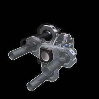
2 PHD Series GRM Clamps Workholding Clamps The Series GRM Clamp continues to be the industryleading pneumatic actuator of choice for material handling solutions worldwide. Its simple design and rugged construction have proven customer satisfaction and loyalty since Three standard sizes (25, 32, and 40 mm bores), 13 standard jaw styles, and countless options and accessories, make the Series GRM Clamp the most versatile and modular clamp in the world. Each and every aspect of the Series GRM Clamp was influenced by you, our customer. We pride ourselves in providing a product that suits your specific application needs. The Series GRM Clamp is a product that is meant to work for you and not a product that you make work. Contact your local distributor or PHD to learn more about Series GRM Clamps. Size 4 Size 1 Size Greater Clamping Forces, Flexibility, Durability, & Low Cost Product Features 1 Fixed or spherical mounting brackets for side or rear mounting 2 Cam design locks clamp in the closed position ensuring part retention if air pressure is lost 3 Adjustable rotation stop allows for multiple jaw openings in one clamp (Sizes 2 and 4) 4 Interchangeable hardenedsteel jaws minimize costly inventory and maximize wear resistance for long life 5 Field repairable in 10 minutes using metric hex wrenches 6 Adjustable hardenedsteel impact plates eliminate damage to body from panel impact 7 Wide and deep jaw throats accommodate difficult clamping applications 8 Selflocking internal threads throughout eliminate need for thread locking adhesives or additional locking components Major Benefits Simple design Compact envelope size Long life High grip force Fast field maintenance Jaws lock in the closed position ensuring part retention if air pressure is lost due to line rupture or power loss Lowest cost of ownership Proven design for longevity Modular jaws and tips easily changed Nonadjustable colorcoded tips Modular mounting brackets Adjustable jaw rotations Hardened adjustable impact plates Integral shock pads Imperial and metric ports and mounting 2 Copyright 2018, by PHD, Inc. All Rights Reserved. Printed in the U.S.A. (800)


3 PHD Series GRM Clamps How to Use This Catalog The Series GRM Clamp is a highly modular pneumatic device, meaning it is capable of many configurations suitable for your specific application needs. This catalog uses a stepbystep approach that walks you through the selection and ordering process for Series GRM Clamps. You will find each section of the catalog targets the specific attributes (options) of the clamp (i.e., mounting options, jaw style options, tip options). At the beginning of each section you will find basic questions related to the options you are investigating. These questions will help you narrow your search and allow for informed decision making. If you are still not sure of your selections and require additional assistance, please contact your local distributor or PHD for technical support. We will be happy to assist you. ETools Table of Contents... Page Ordering Directions...4 Step 1 Model...5 Step 2 Unit Size...6 Step 3 Mounting...8 Step 4 Jaw Styles & Openings...20 Step 5 Design Number...40 Step 6 Tips...42 Step 7 Port Fittings...60 Step 8 Accessory Options...62 Rebuild Program...83 Exploded Assemblies...84 Other Clamp Solutions...95 For GRM product videos, animated application design examples, and guided tours, visit our Learn site. CAD & Sizing Assistance Use PHD s free online Product Sizing and CAD Configurator (800)
4 ORDERING DIRECTIONS PHD Series GRM Clamps This catalog uses a stepbystep approach that walks you through the selection and ordering process for Series GRM Clamps. You will find each section of the catalog targets the specific attributes (options) of the clamp (i.e., mounting options, jaw style options, tip options). UNIT SIZE (BORE) 1 25 mm 2 32 mm 4 40 mm Refer to Unit Size section. JAW STYLE OPTIONS Size 1 S & F Size 2 S, C, D, F, G, H, J, K, L, M, N, P, & R Size 4 S, F, G, H, & J Refer to Jaw Styles & Openings section. JAW A OPENINGS Refer to Jaw Styles & Openings section. Helpful reminder: Look for the shaded headers and charts throughout the catalog that correspond to the colors shown in the frames below. JAW A JAW TIP OPTIONS BLANK No Tip Refer to Tips section. PORT FITTINGS OPTIONS BLANK No Fittings Refer to Port Fittings section. GRM Step 2 Step 4 Step 4 Step 6 Step 7 Step 8 ACCESSORY 2 S S 2 75 DCB 75 DDB LAA OPTIONS Step 1 Step 3 Step 5 Step 4 Step 6 MODEL MOUNTING OPTIONS Refer to Mounting section. DESIGN NO. 2 Imperial 6 Metric Refer to Design No. section. JAW B OPENINGS Refer to Jaw Styles & Openings section. JAW B JAW TIP OPTIONS BLANK No Tip Refer to Tips section. 4 (800)
5 PHD Series GRM Clamps MODEL Step 1 Model: GRM This step is already done for you. GRM is the 3 digit prefix used by PHD to define this product line. Two GRM1xS clamps grab slip sheet between layers of cans in depalletizing machine Six GRM2xN clamps are used for this automated pallet binding machine. Two GRM2xS clamps are used in coffee packaging application to move filled bags from conveyor to cartons. Four GRM2xS clamps handle sheet metal for automotive/metal stamping press. (800)

, GRM2 (medium), GRM4 (large) b. No All GRM Clamps apply c.")
6 UNIT SIZE PHD Series GRM Clamps Step 2 Unit Size Choosing the correct size of GRM Clamp depends solely on the application. Knowing the answers to the following questions will help refine the selection process. If you are still unsure about your application and sizing selection, contact your local distributor or a member of PHD for assistance. (Refer to charts on page 7.) 1. Does your application have space restrictions? a. Yes GRM1 (small), GRM2 (medium), GRM4 (large) b. No All GRM Clamps apply c. Unsure Refer to Chart 1 Unit Size Comparison for base unit envelope sizes and remember to include bolton options and accessories in your space calculations. 2. Does your application have weight restrictions? a. Yes GRM1 (light), GRM2 (medium), GRM4 (heavy) b. No All GRM Clamps apply c. Unsure Refer to Chart 1 Unit Size Comparison for base unit weights and remember to include bolt on options and accessories in your weight calculations. 3. What is the minimum air pressure that will be available for each clamp? a. Above 60 psi [4 bar] All GRM Clamps will cycle at 30 psi [2 bar] minimum, but PHD recommends a minimum of 60 psi [4 bar] for continuous operation. b. Below 60 psi [4 bar] Consult your local distributor or PHD Customer Service. 4. Does your application have grip force requirements (1)? a. Yes GRM1 (0 225 lb [ N]) GRM2 (0 676 lb [ N]) GRM4 (0 875 lb [ N]) b. No All GRM Clamps apply c. Unsure Refer to Chart 1 Unit Size Comparison for total grip force or B08 and B10 options in the Accessory Options section for increased grip force. 5. Are there variables that will negatively affect the carrying capability of the clamp such as lubricants and fluids or low friction coatings (2)? a. Yes Consult your local distributor or PHD Customer Service b. No All GRM Clamps apply NOTES: 1) Total grip force is based on 87 psi [6 bar] air pressure. 2) Variables associated with friction coefficients (external fluids, surface finish, coatings, plating, tip selection, air pressure, and others) may affect the performance of the clamp in its ability to grip and hold the work piece rigidly, without slippage, and/or loss of control of the part. 6 (800)
7 PHD Series GRM Clamps UNIT SIZE JAW STYLES S SIZE UNIT SIZE COMPARISON (CHART 1) TOTAL GRIP MAX. ENVELOPE SIZE (3) FORCE (1) (2) LENGTH WIDTH HEIGHT MAX. WEIGHT (4) lb N in mm in mm in mm lb kg C & D F G H & J K L & M N & P R NOTES: 1) Based on 87 psi [6 bar] air pressure. 2) Refer to B08 and B10 options in Accessory Options section for increased grip force. 3) Maximum envelope size of base unit without options. 4) Maximum weight of base unit without options. PAGE MAX. ENVELOPE SIZE LENGTH LENGTH LENGTH HEIGHT HEIGHT HEIGHT WIDTH SIZE top or bottom view UNIT SIZE COMPARISON (CHART 2) CYLINDER PARAMETERS (1) CYCLE TIME PRESSURE LIMITS TEMPERATURE MAX. DISPLACEMENT OPEN OR LIMITS(3) BORE Ø STROKE OPEN CLOSE CLOSE (2) min max min max in mm in mm in 3 cm 3 in 3 cm 3 sec psi bar psi bar F C F C NOTES: 1) Refer to B08 and B10 options in Accessory Options section for other cylinder parameters. 2) Based on 87 psi [6 bar] air pressure. 3) Refer to G11 option in Accessory Options section for hightemp applications All dimensions are reference only unless specifically toleranced. (800)
8 MOUNTING PHD Series GRM Clamps Step 3 Mounting PHD has a wide variety of standard and accessory mounts available for the Series GRM Clamp. Use the following questions and graphical representations to help in your selection process. If you are unable to locate a mount that suits your application needs, contact your local distributor or a member of PHD for assistance. 1. What will the clamp be mounted to? a. Rigid surface P or T or B12, B14, and B16 options in the Accessory Options section b. Tubing All mounts except P or T or B12, B14, and B16 options in the Accessory Options section 2. Does the mount need to be adjustable? a. Yes All mounts except P or T or B12, B14, and B16 options in the Accessory Options section b. No P or T or B12, B14, and B16 options in the Accessory Options section 3. Do you require a metric clamp (1/8 BSPP ports) with metric mounting or imperial clamp (1/8 NPT ports) with imperial mounting (1) (2) (3)? a. Yes All metric clamps come standard with metric mounting and all imperial clamps come standard with imperial mounting. b. No Go to question 4 4. Do you require a metric clamp (1/8 BSPP ports) with imperial mounting (1) (2) (3)? a. Yes P, T, M03, M25, M27, M29, M39, M40, M44M47 b. No See question 5 5. Do you require an imperial clamp (1/8 NPT ports) with metric mounting (1) (2) (3)? a. Yes P, T, M01, M07, M21M24, M28, M30, M36M38, or M41M43 b. No See question 3 6. Does the clamp need to be a dropin replacement for a competitive product? a. Yes Consult your local distributor or PHD Customer Service and provide make, model number, and mounting requirements of the competitive product (mounting pattern/ tubing dimensions and tolerances requested). b. No All mounts apply 7. How to order (4) (5)? a. For standard mounts A, B, C, P, R, S, T, or W NOTES: Example ordering data: GRM2AS245SDB45SDBLAA b. For accessory mounts Mxx Example ordering data: GRM2TS245SDB45SDBLAAM01 c. For GRM1 standard mounts C, R, S, or W Example ordering data: GRM1CS250SDB50SDBLAAB11 d. For GRM1 accessory mounts Mxx Example ordering data: GRM1TS250SDB50SDBLAAB11 M01 1) Unless otherwise specified, metric units have metric ports and mounting. Imperial units have imperial ports and mounting. 2) Rear mounting plate (P option) will accommodate metric and imperial fasteners. See mounting bracket dimensions page. 3) Rear mounting threads (T option) come standard on all Series GRM Clamps and are metric only. See mounting bracket dimensions page. 4) B11 option required for Series GRM1 Clamps when specifying standard or accessory side mounting brackets. Rear mounting brackets are not available for Series GRM1 Clamps. See B11 option in Accessory Options section. 5) Rear mounting threads (T option) must be specified when ordering an accessory mount (Mxx option). In addition to these mounting options, we have created custom mounting brackets for specific applications. Some examples of these specials are: A Rear Compliant Mounting Bracket that can rotate up to ±15 to grip a panel that is not oriented properly. This bracket then selfcenters itself after releasing the panel. B Rear mounting brackets with solid or hollow shapes or spherical balls for adjustability. C Mounting brackets such as angle brackets that mount to the side of the clamp body. D Side mounting spherical or nonspherical brackets that can accommodate square or round mounting tubes up to 11/2 in or 40 mm. Side Mounting Bracket with a fixed spherical ball. E 8 (800)


")

9 PHD Series GRM Clamps MOUNTING Mounts rotate around the clamp Clamp body rotates around the tube B A B C D D E (800)

 must be specified when ordering an accessory mount (Mxx option).")


10 MOUNTING PHD Series GRM Clamps ORDERING DATA: GRM 2 S S Mxx CLAMP SIZE 1 GRM1 2 GRM2 4 GRM4 STANDARD MOUNTS DESIGN NO. 2 Imperial 6 Metric ACCESSORY MOUNTS Note: Rear mounting threads (T option) must be specified when ordering an accessory mount (Mxx option). 90 SPHERICAL MOUNTING BRACKET MODEL NUMBER OR ACCESSORY CODE GRMxCx2 GRMxCx6 GRMxTx2M21 GRMxTx6M39 C MOUNTING TUBE SIZE 1.0 in 25.0 mm 25.0 mm 1.0 in NONSPHERICAL MOUNTING BRACKET MODEL NUMBER OR ACCESSORY CODE GRMxRx2 GRMxRx6 GRMxTx2M22 GRMxTx6M46 R S W MOUNTING TUBE SIZE 1.0 in 25.0 mm 25.0 mm 1.0 in SPHERICAL MOUNTING BRACKET MODEL NUMBER OR ACCESSORY CODE GRMxSx2 GRMxSx6 GRMxTx2M23 GRMxTx6M47 MOUNTING TUBE SIZE 1.0 in 25.0 mm 25.0 mm 1.0 in OVERSIZE SPHERICAL MOUNTING BRACKET MODEL NUMBER OR ACCESSORY CODE GRMxWx2 GRMxWx6 GRMxTxxM01 GRMxTxxM07 GRMxTx6M25 GRMxTx2M42 MOUNTING TUBE SIZE 1.25 in 33.3 mm 30.0 mm 32.0 mm 1.25 in 33.3 mm SPHERICAL MOUNTING BRACKET WITH M8 FASTENERS ACCESSORY CODE GRMxTxxM27 GRMxTxxM28 GRMxTxxM29 GRMxTxxM30 GRMxTxxM36 GRMxTxxM37 M27M30 M36M37 MOUNTING TUBE SIZE 1.0 in 25.0 mm 1.25 in 33.3 mm 30.0 mm 32.0 mm SPHERICAL MOUNTING BRACKET FOR SQUARE TUBING ACCESSORY CODE GRMxTxxM38 MOUNTING TUBE SIZE 19.0 mm M38 10 (800) All dimensions are reference only unless specifically toleranced.


![MOUNTING THREAD SIZE M5 x.450 [11.4] DP M6 x.413 [10.5] DP M8 x.512 [13.](/docs-images/90/102854416/images/11-6.jpg "0] DP M03 M40M41 ACCESSORY CODE GRM2xx OR GRM4xx INTERNAL MOUNTING DIAMETER EXTERNAL")
![MOUNTING DIAMETER GRMxTxxM03 1.0 in [25.0 mm] 1.874 in [47.](/docs-images/90/102854416/images/11-7.jpg "6 mm] GRM2xx OR GRM4xx ACCESSORY CODE GRMxTxxM40 GRMxTxxM41 MOUNTING TUBE SIZE 1.")
11 PHD Series GRM Clamps MOUNTING REAR MOUNTING SIDE MOUNTING A B P T GRM2xx OR GRM4xx MODEL NUMBER OR ACCESSORY CODE GRMxAx2 GRMxAx6 GRMxBx2 GRMxBx6 GRMxTx2M24 GRMxTx2M43 GRMxTx6M44 GRMxTx6M45 MOUNTING TUBE SIZE 1.0 in 25.0 mm 1.25 in 33.3 mm 25.0 mm 33.3 mm 1.0 in 1.25 in Note: Spherical or Nonspherical in one mount GRM2xx OR GRM4xx MODEL NUMBER GRM2Px GRM4Px MOUNTING FASTENER SIZE 1/4 [M6] 5/16 [M8] MODEL NUMBER GRM1Tx GRM2Tx GRM4Tx MOUNTING THREAD SIZE M5 x.450 [11.4] DP M6 x.413 [10.5] DP M8 x.512 [13.0] DP M03 M40M41 ACCESSORY CODE GRM2xx OR GRM4xx INTERNAL MOUNTING DIAMETER EXTERNAL MOUNTING DIAMETER GRMxTxxM in [25.0 mm] in [47.6 mm] GRM2xx OR GRM4xx ACCESSORY CODE GRMxTxxM40 GRMxTxxM41 MOUNTING TUBE SIZE 1.0 in 25.0 mm Note: Spherical or Nonspherical in one mount All dimensions are reference only unless specifically toleranced. (800)
 25.0 mm 25.0 mm M4 (M39) 1.000 in 1.000 in M5 3.000 76.2 3.500 88.9 M6 4.850 123.2 5.900 149.9 M8 2.500 63.5 3.350 85.1 M11 2.500 63.5 2.500 63.5 M13 0.197 5.0 0.197 5.0 M14 0.236 6.")
12 SIDE MOUNTING SIZES 1, 2, & 4 PHD Series GRM Clamps GRMx C x or GRMxTx M21 M39 90 SPHERICAL MOUNTING BRACKET MODEL NUMBER LETTER GRM1B11 & GRM2 GRM4 (GRM2B08) DIM in mm in mm M4 (C) M4 (M21) 25.0 mm 25.0 mm M4 (M39) in in M M M M M M M11 M6 4X M13 HEX Ø M4 TUBE M X M14 HEX CLAMP KIT NUMBER WEIGHT ADDER SIZE IMPERIAL METRIC M21 M39 lb kg 1B , 2B M5 CLAMP CAN BE ROTATED 360 WITHIN BRACKET GRMx R x or GRMxTx M22 M46 NONSPHERICAL MOUNTING BRACKET M5 M7 Ø M4 TUBE M6 M8 MODEL NUMBER LETTER GRM1B11 & GRM2 GRM4 (GRM2B08) DIM in mm in mm M4 (R) M4 (M22) 25.0 mm 25.0 mm M4 (M46) in in M M M M CLAMP CAN BE ROTATED 360 WITHIN BRACKET [5.0] HEX CLAMP KIT NUMBER WEIGHT ADDER SIZE IMPERIAL METRIC M22 M46 lb kg 1B , 2B (800) All dimensions are reference only unless specifically toleranced.
 DIM in mm in mm M4 (S) 1.000 25.0 1.000 25.0 M4 (M23) 25.")
13 PHD Series GRM Clamps SIDE MOUNTING SIZES 1, 2, & 4 GRMx S x or GRMxTx M23 M47 SPHERICAL MOUNTING BRACKET GRMx W x or GRMxTx M01 M07 M25 M42 OVERSIZE SPHERICAL MOUNTING BRACKET M5 M7 30 M4 TUBE 30 M6 M8 CLAMP CAN BE ROTATED 360 WITHIN BRACKET [5.0] HEX FOR SPHERICAL MOUNTING BRACKET: MODEL NUMBER LETTER GRM1B11 & GRM2 GRM4 (GRM2B08) DIM in mm in mm M4 (S) M4 (M23) 25.0 mm 25.0 mm M4 (M47) in in M M M M CLAMP KIT NUMBER WEIGHT ADDER SIZE IMPERIAL METRIC M23 M47 lb kg 1B , 2B FOR OVERSIZE SPHERICAL MOUNTING BRACKET: MODEL NUMBER LETTER GRM1B11 & GRM2 GRM4 (GRM2B08) DIM in mm in mm M4 (W) M4 (M01) 30.0 mm 30.0 mm M4 (M07) 32.0 mm 32.0 mm M4 (M25) in in M4 (M42) 33.3 mm 33.3 mm M M M M CLAMP KIT NUMBER WEIGHT ADDER SIZE IMPERIAL METRIC M01 M07 M25 M42 lb kg 1B , 2B All dimensions are reference only unless specifically toleranced. (800)

14 SIDE MOUNTING SIZES 1, 2, & 4 PHD Series GRM Clamps GRMxTx M27 M30 SPHERICAL MOUNTING BRACKET WITH M8 FASTENERS GRMxTx M36 M37 SPHERICAL MOUNTING BRACKET WITH M8 FASTENERS M5 M9 M5 M7 30 Ø M4 TUBE 30 M6 M8 M6 M8 GRM1Tx & GRM2Tx CLAMP CAN BE ROTATED 360 WITHIN BRACKET GRM4Tx [6.0] HEX CLAMP CAN BE ROTATED 360 WITHIN BRACKET GRM1TxB11 & GRM2Tx LETTER DIMENSION ACCESSORY M5 M6 M7 M8 M9 CODE M4 in mm in mm in mm in mm in mm M in M mm M in M mm M mm M mm GRM4Tx (GRM2TxB08) LETTER DIMENSION ACCESSORY M5 M6 M7 M8 M9 CODE M4 in mm in mm in mm in mm in mm M in M mm M in M mm M mm M mm ACCESSORY CODE GRM1TxB11 & GRM2Tx KIT NUMBER WEIGHT ADDER lb kg M M M M M M ACCESSORY CODE GRM4Tx (GRM2TxB08) KIT NUMBER WEIGHT ADDER lb kg M M M M M M (800) All dimensions are reference only unless specifically toleranced.

15 PHD Series GRM Clamps SIDE MOUNTING SIZES 1, 2, & 4 GRMxTx M38 SPHERICAL MOUNTING BRACKET FOR SQUARE TUBE M5 30 M7 M4 TUBE M6 M8 30 CLAMP CAN BE ROTATED 360 WITHIN BRACKET [5.0] HEX CLAMP SIZE GRM1TxB11 GRM2Tx GRM4Tx GRM2TxB08 M4 LETTER DIMENSION M5 M6 M7 M8 in mm in mm in mm in mm 19.0 mm mm CLAMP SIZE KIT NUMBER WEIGHT ADDER lb kg 1B , 2B All dimensions are reference only unless specifically toleranced. (800)
16 REAR MOUNTING SIZES 2 & 4 PHD Series GRM Clamps GRMx A x or GRMxTx M24 M44 REAR MOUNTING BRACKET (Spherical or NonSpherical) GRMx B x or GRMxTx M43 M45 OVERSIZE REAR MOUNTING BRACKET (Spherical or NonSpherical) M [5.0] HEX M7 INSTALL MOUNTING TUBE TO THIS SURFACE FOR NONSPHERICAL MOUNTING M M4 TUBE M8 INSTALL MOUNTING TUBE ONLY THROUGH BALL FOR SPHERICAL MOUNTING FOR REAR MOUNTING BRACKET: LETTER DIM GRM2 MODEL NUMBER GRM4 (GRM2B08) in mm in mm M4 (A) M4 (M24) 25.0 mm 25.0 mm M4 (M44) in in M M M M CLAMP KIT NUMBER WEIGHT ADDER SIZE IMPERIAL METRIC M24 M44 lb kg , 2B FOR OVERSIZE REAR MOUNTING BRACKET: LETTER DIM GRM2 MODEL NUMBER GRM4 (GRM2B08) in mm in mm M4 (B) M4 (M43) 33.3 mm 33.3 mm M4 (M45) in in M M M M CLAMP KIT NUMBER WEIGHT ADDER SIZE IMPERIAL METRIC M43 M45 lb kg , 2B (800) All dimensions are reference only unless specifically toleranced.

17 PHD Series GRM Clamps REAR MOUNTING SIZES 1, 2, & 4 GRMx P REAR MOUNTING PLATE M10 HEX M5 4X THRU HOLE FOR M7 SHCS M8 M3 M6 M4 LETTER DIM MODEL NUMBER GRM4Px GRM2Px (GRM2PxB08) in mm in mm M M M M M7 1/4 M6 5/16 M8 M M CLAMP KIT NUMBER WEIGHT ADDER SIZE IMPERIAL METRIC lb kg , 2B GRMx T REAR MOUNTING THREADS (Standard on all clamps) MR1 GRM1 T MR2 4X MR3 LOCKING THREAD MR1 3X MR3 LOCKING THREAD GRM2 T MR2 LETTER DIM MODEL NUMBER GRM1Tx GRM2Tx GRM4Tx (GRM2TxB08) in mm in mm in mm MR MR MR3 M5 x 0.8 x [11.4] DP M6 x 1.0 x [10.5] DP M8 x 1.25 x [13.0] DP MR1 3X MR3 LOCKING THREAD GRM4 T MR2 All dimensions are reference only unless specifically toleranced. (800)
18 REAR MOUNTING SIZES 2 & 4 PHD Series GRM Clamps GRMxTx M03 RIGID REAR MOUNTING BRACKET [5.0] HEX [25.7] 3X M3 HEX [63.5] [22.5] M ± [47.60 ± 0.08] M5 CLAMP SIZE LETTER DIMENSION M3 M4 M5 in mm in mm in mm GRM2Tx GRM4Tx GRM2TxB CLAMP SIZE KIT NUMBER WEIGHT ADDER lb kg , 2B (800) All dimensions are reference only unless specifically toleranced.
19 PHD Series GRM Clamps REAR MOUNTING SIZES 2 & 4 GRMxTx M40 1" REAR MOUNTING BRACKET (Spherical or NonSpherical) GRMxTx M41 25 mm REAR MOUNTING BRACKET (Spherical or NonSpherical) M5 M6 M4 TUBE M9 HEX M7 M8 INSTALL MOUNTING TUBE TO THIS SURFACE FOR NONSPHERICAL MOUNTING M M3 M1 INSTALL MOUNTING TUBE ONLY THROUGH BALL FOR SPHERICAL MOUNTING CLAMP SIZE LETTER DIMENSION M1 M2 M3 M4 M5 M6 M7 M8 M9 in mm in mm in mm in mm in mm in mm in mm in mm in mm GRM2Tx GRM4Tx GRM2TxB ACCESSORY CODE GRM2Tx KIT NUMBER WEIGHT ADDER lb kg M M GRM4Tx (GRM2TxB08) ACCESSORY KIT WEIGHT ADDER CODE NUMBER lb kg M M All dimensions are reference only unless specifically toleranced. (800)
.")
20 JAW STYLES & OPENINGS PHD Series GRM Clamps Step 4 Jaw Styles & Openings The Series GRM Clamp has 13 standard jaw styles and numerous jaw openings available to fit your application requirements. Use the following questions and graphical representations in this section to help in your selection process. Many of the jaw styles require the use of bolton tooling (tips). Refer to the tip section before making your final jaw style selection. If you are unable to locate a jaw style that suits your application needs, contact your local distributor or a member of PHD for assistance. NOTES: 1) The axis of the clamp is defined by the direction of piston motion. 2) Refer to the tip section for standard and accessory tips that are suited for specific material shapes, sizes, and configurations. 3) Spherical mounting brackets allow the clamp to pivot, swivel, and rotate, thus ensuring precise alignment at the point of grip. 1. What is the primary function of the clamp? a. Blank loading or sheet separation C, D, H, J, L, or M b. Material transfer All jaw styles apply c. None of the above Consult your local distributor or PHD Customer Service for assistance. 2. Do you require tips to be mounted to the jaw(s)? a. Tip on one jaw C, D, H, J, L, or M b. Tips on two jaws S, F, G, K, or R c. No tips required N or P 3. Does your application have space restrictions around the point of grip? a. Yes S, C, F, G, H, K, L, N, or R b. No All jaw styles apply 4. Does your application require the axis of the clamp to be parallel or perpendicular to the material being gripped (1)? a. Parallel S, C, D, G, H, J, L, M, N, P, or R b. Perpendicular F or K 13 standard jaw styles, numerous jaw openings, and literally hundreds of nonstandard jaws make the Series GRM Clamp the most modular clamp in the world. Here are just a few of the many nonstandard jaw applications: A Special jaw that receives a 1.000" [25.4 mm] tube allows for vacuum cups and related tooling. B Removal of one jaw turns a GRM Clamp into a locking hold down clamp. C Elongated jaws for applications where the point of grip is further inward from the edge of the part. D Aluminum jaws can reduce the weight of the clamp by up to 0.54 lb [0.25 kg]. E Special needlenose jaws that are only 0.188" [4.8 mm] wide and come equipped with integral teeth used to grip material in extremely narrow spaces. F Clamp with elongated M style jaws to replace a competitive product. 5. Is the point of grip flat or does it have shape (2) (3)? a. Flat All jaw styles b. Shaped (curved) S, F, G, K, or R c. Shaped (angled) All jaw styles d. Shaped (irregular) S, F, G, K, or R A 6. Is the point of grip beyond a bend or fold in the material? a. Yes S, C, D, F, G, H, J, L, or M b. No Go to question 5 20 (800)


21 PHD Series GRM Clamps JAW STYLES & OPENINGS B D C D E F All dimensions are reference only unless specifically toleranced. (800)


22 STANDARD JAW STYLE S SIZES 1, 2, & 4 PHD Series GRM Clamps S jaw style GRM1xS Jaw Design Benefits Jaws lock in closed position. Accepts standard and custom tooling. Sizes 2 and 4 s adjustable external rotation stop allows for multiple jaw openings in one clamp. Sizes 2 and 4 s jaws are designed with wide and deep jaw throats to accommodate nonflat applications. Size 1 has the same grip force as size 2. Many jaw rotations available for wide variety of applications. Impact plates are standard and installed on all Series GRM Clamps. Other impact plate designs are available. See exploded assembly parts section. GRM2xS GRM4xS Available Jaw Rotations = Available Combination = Not Available For other configurations, consult your local distributor or PHD, Inc. NOTE: 1) The 0 jaw rotates open slightly during the clamp cycle. The 0 jaw returns to 0 position as the opposing jaw reaches the fully open or fully closed positions. GRM1xS JAW A JAW STYLE OPTION S JAW B JAW STYLE OPTION S JAW B JAW STYLE OPTION S JAW B GRM4xS GRM2xS JAW A JAW A (800)
23 PHD Series GRM Clamps STANDARD JAW STYLE S SIZES 1, 2, & 4 Dimensions B4 (CLOSED) M2 (CLOSED) LETTER DIMENSIONS MODEL NUMBER GRM1xS GRM2xS GRM4xS in mm in mm in mm B4 (CLOSED) F M2 (CLOSED) JAW A JAW B J1 (OPEN MAX) LETTER DIMENSIONS J1 (OPEN) MODEL NUMBER ROTATIONS GRM1xS in mm 14 x x x x x x x x x F5 LETTER DIMENSIONS J1 (OPEN) MODEL NUMBER ROTATIONS GRM2xS GRM4xS in mm in mm 22 x x x x x x x x J1 (OPEN MAX) LETTER DIMENSIONS J1 (OPEN) LETTER DIMENSIONS J1 (OPEN) MODEL NUMBER ROTATIONS GRM1xS in mm 00 x x x x x x x x x x x x x x x MODEL NUMBER ROTATIONS GRM2xS GRM4xS in mm in mm 00 x x x x x x x x x x x x x x x J1 (OPEN MAX) LETTER DIMENSIONS J1 (OPEN) MODEL NUMBER ROTATIONS GRM1xS GRM2xS GRM4xS in mm in mm in mm 00 x x x All dimensions are reference only unless specifically toleranced. (800)


24 CHISEL JAW STYLES C & D SIZE 2 PHD Series GRM Clamps C D jaw style jaw style Jaw Design Benefits Jaws lock in closed position. Upper jaw accepts standard and custom tooling. Lower jaw is a compact design ideal for blank loading and sheet separation applications. Adjustable external rotation stop allows for multiple jaw openings in one clamp. Many jaw rotations available for wide variety of applications. Impact plates are standard and installed on all Series GRM Clamps. Other impact plate designs are available. See exploded assembly parts section. GRM2xC Single Chisel GRM2xD Double Chisel Available Jaw Rotations = Available Combination = Not Available For other configurations, consult your local distributor or PHD, Inc. GRM2xC, GRM2xD JAW A JAW STYLE OPTIONS C & D JAW B NOTE: 1) The 0 jaw rotates open slightly during the clamp cycle. The 0 jaw returns to 0 position as the opposing jaw reaches the fully open or fully closed positions. 24 (800)
25 PHD Series GRM Clamps CHISEL JAW STYLES C & D SIZE 2 Dimensions B4 (CLOSED) M2 (CLOSED) JAW B JAW A J1 (OPEN MAX) MODEL NUMBER LETTER GRM2xC GRM2xD DIMENSIONS in mm in mm B4 (CLOSED) F J M2 (CLOSED) GRM2xC GRM2xD J9 J9 F5 F5 LETTER DIMENSIONS J1 (OPEN) MODEL NUMBER ROTATIONS GRM2xC, GRM2xD in mm 11 x x x x x x x x x J1 (OPEN MAX) LETTER DIMENSIONS J1 (OPEN) MODEL NUMBER ROTATIONS GRM2xC, GRM2xD in mm 00 x x x x x J1 (OPEN MAX) LETTER DIMENSIONS J1 (OPEN) MODEL NUMBER ROTATIONS GRM2xC, GRM2xD in mm 22 x x x x All dimensions are reference only unless specifically toleranced. (800)


 The 0")
26 FLANGE JAW STYLE F SIZES 1, 2, & 4 PHD Series GRM Clamps F jaw style GRM1xF Jaw Design Benefits Jaws lock in closed position. Accepts standard and custom tooling. Adjustable external rotation stop allows for multiple jaw openings in one clamp. Ideal to grip on bends or flanges. Impact plates are standard and installed on all Series GRM Clamps. Other impact plate designs are available. See exploded assembly parts section. GRM2xF GRM4xF Available Jaw Rotations = Available Combination GRM1xF JAW STYLE OPTION F JAW B 0 JAW A = Not Available For other configurations, consult your local distributor or PHD, Inc. GRM2xF JAW STYLE OPTION F JAW B 0 22 JAW A GRM4xF JAW STYLE OPTION F JAW B 0 JAW A NOTE: 1) The 0 jaw rotates open slightly during the clamp cycle. The 0 jaw returns to 0 position as the opposing jaw reaches the fully open or fully closed positions. 26 (800)
27 PHD Series GRM Clamps FLANGE JAW STYLE F SIZES 1, 2, & 4 Dimensions J2 (OPEN MAX) B4 (CLOSED) B4 (OPEN) M2 (CLOSED) J1 (OPEN MAX) (JAW A ROTATES) M3 (CLOSED) J1 (OPEN MAX) (BOTH JAWS ROTATE) MODEL NUMBER LETTER ROTATIONS GRM1xF DIMENSIONS in mm 30 x B4 (OPEN) 60 x B4 (CLOSED) F ALL M2 (CLOSED) M3 (CLOSED) MODEL NUMBER LETTER ROTATIONS GRM2xF GRM4xF DIMENSIONS in mm in mm 50 x B4 (OPEN) 85 x x B4 (CLOSED) F ALL M2 (CLOSED) M3 (CLOSED) F5 LETTER DIMENSIONS J1 (OPEN) LETTER DIMENSIONS J1 (OPEN) J2 (OPEN) MODEL NUMBER ROTATIONS GRM1xF in mm 30 x x MODEL NUMBER ROTATIONS GRM2xF GRM4xF in mm in mm 50 x x x x x All dimensions are reference only unless specifically toleranced. (800)


28 TOOLABLE JAW STYLE G SIZES 2 & 4 PHD Series GRM Clamps G jaw style Jaw Design Benefits Jaws lock in closed position. Accepts custom tooling. Adjustable external rotation stop allows for multiple jaw openings in one clamp. Designed with large space between jaws to accommodate nonflat and large material applications. Impact plates are standard and installed on all Series GRM Clamps. Other impact plate designs are available. See exploded assembly parts section. GRM2xG Available Jaw Rotations = Available Combination = Not Available For other configurations, consult your local distributor or PHD, Inc. GRM2xG JAW A JAW STYLE OPTION G JAW B JAW STYLE OPTION G JAW B GRM4xG JAW A NOTE: 1) The 0 jaw rotates open slightly during the clamp cycle. The 0 jaw returns to 0 position as the opposing jaw reaches the fully open or fully closed positions. 28 (800)
29 PHD Series GRM Clamps TOOLABLE JAW STYLE G SIZES 2 & 4 Dimensions B4 (CLOSED) M2 (CLOSED) SIZE 4 SIZE 2 JAW A J1 (OPEN MAX) MODEL NUMBER LETTER GRM2xG GRM4xG DIMENSIONS in mm in mm B4 (CLOSED) F M2 (CLOSED) SIZE 4 SIZE 2 JAW B F5 LETTER DIMENSIONS J1 (OPEN) MODEL NUMBER ROTATIONS GRM2xG GRM4xG in mm in mm 11 x x x x x x x x x x All dimensions are reference only unless specifically toleranced. (800)


30 SHOVEL JAW STYLES H & J SIZES 2 & 4 PHD Series GRM Clamps H J jaw style jaw style Jaw Design Benefits Jaws lock in closed position. Upper jaw accepts standard and custom tooling. Lower jaw is a compact design ideal for blank loading and sheet separation applications. Adjustable external rotation stop allows for multiple jaw openings in one clamp. Impact plates are standard and installed on all Series GRM Clamps. Other impact plate designs are available. See exploded assembly parts section. GRM2xH Single Shovel GRM2xJ Double Shovel Available Jaw Rotations = Available Combination = Not Available For other configurations, consult your local distributor or PHD, Inc. GRM2xH, GRM2xJ JAW A JAW STYLE OPTIONS H & J JAW B 0 GRM4xH, GRM4xJ JAW A JAW STYLE OPTIONS H & J JAW B 0 NOTE: 1) The 0 jaw rotates open slightly during the clamp cycle. The 0 jaw returns to 0 position as the opposing jaw reaches the fully open or fully closed positions. 30 (800)
31 PHD Series GRM Clamps SHOVEL JAW STYLES H & J SIZES 2 & 4 Dimensions B4 (CLOSED) M2 (CLOSED) B5 (CLOSED) JAW B JAW A J1 (OPEN MAX) LETTER DIMENSIONS MODEL NUMBER GRM2xH GRM2xJ GRM4xH GRM4xJ in mm in mm in mm in mm B4 (CLOSED) B5 (CLOSED) F J M2 (CLOSED) GRM2xH J9 F5 LETTER DIMENSIONS J1 (OPEN) MODEL NUMBER ROTATIONS GRM2xH, GRM2xJ GRM4xH, GRM4xJ in mm in mm 22 x x x x GRM2xJ J9 F5 J1 (OPEN MAX) MODEL NUMBER LETTER ROTATIONS GRM2xH, GRM2xJ GRM4xH, GRM4xJ DIMENSIONS in mm in mm J1 (OPEN) 15 x All dimensions are reference only unless specifically toleranced. (800)

32 HOOK JAW STYLE K SIZE 2 PHD Series GRM Clamps K jaw style Jaw Design Benefits Jaws lock in closed position. Accepts standard and custom tooling. Adjustable external rotation stop allows for multiple jaw openings in one clamp. Short overall length to save space between rails. Impact plates are standard and installed on all Series GRM Clamps. Other impact plate designs are available. See exploded assembly parts section. GRM2xK Available Jaw Rotations = Available Combination = Not Available GRM2xK JAW STYLE OPTION K JAW B JAW A For other configurations, consult your local distributor or PHD, Inc. NOTE: 1) The 0 jaw rotates open slightly during the clamp cycle. The 0 jaw returns to 0 position as the opposing jaw reaches the fully open or fully closed positions. 32 (800)
33 PHD Series GRM Clamps HOOK JAW STYLE K SIZE 2 Dimensions B4 (OPEN) B5 B4 (CLOSED) M2 (CLOSED) J2 (OPEN MAX) J1 (OPEN MAX) (JAW A ROTATES) J1 (OPEN MAX) (BOTH JAWS ROTATE) F5 M3 (CLOSED) LETTER DIMENSIONS ROTATIONS MODEL NUMBER in GRM2xK mm 50 x B4 (OPEN) 25 x B4 (CLOSED) 50 x B F5 ALL M2 (CLOSED) M3 (CLOSED) LETTER DIMENSIONS ROTATIONS MODEL NUMBER in GRM2xK mm 50 x J1 (OPEN) 25 x x J2 (OPEN) 50 x All dimensions are reference only unless specifically toleranced. (800)

34 FLAT SHOVEL JAW STYLES L & M, SIZE 2 PHD Series GRM Clamps L M jaw style jaw style Jaw Design Benefits Jaws lock in closed position. Adjustable internal rotation stop allows for multiple jaw openings in one clamp. Completely fixed lower jaw. Upper jaw does not swing through the bottom of the clamp. Ideal for limited spaces. Impact plates are standard and installed on all Series GRM Clamps. Other impact plate designs are available. See exploded assembly parts section. GRM2xL Single Flat Shovel GRM2xM Double Flat Shovel Available Jaw Rotations = Available Combination = Not Available GRM2xL, GRM2xM JAW A JAW STYLE OPTIONS L & M JAW B 0 For other configurations, consult your local distributor or PHD, Inc. 34 (800)
35 PHD Series GRM Clamps FLAT SHOVEL JAW STYLES L & M, SIZE 2 Dimensions B4 (CLOSED) M2 (CLOSED) B2 MP1 M JAW A J1 (OPEN MAX) B1 MP2 4X THRU HOLE FOR MP3 SHCS MT2 4X MT3 LOCKING THREAD MT4 DEEP MIN MP4 B5 JAW B GRM2xL J9 F5 GRM2xM J9 F5 MODEL NUMBER LETTER GRM2xL GRM2xM DIMENSIONS in mm in mm B B B4 (CLOSED) B F J M2 (CLOSED) MP MP MP3 1/4 M6 1/4 M6 MP M MT MT3 M6 x 1.0 M6 x 1.0 MT MODEL NUMBER LETTER DIMENSIONS ROTATIONS GRM2xL, GRM2xM in mm 22 x J1 (OPEN) 45 x x All dimensions are reference only unless specifically toleranced. (800)
. Compact jaw design ideal for limited spaces and blank loading applications.")


36 NEEDLENOSE N & HAMMERHEAD P JAW STYLES SIZE 2 PHD Series GRM Clamps N P jaw style jaw style Jaw Design Benefits Jaws lock in closed position over a wide panel thickness range (0.0 to 4.0 mm). Compact jaw design ideal for limited spaces and blank loading applications. Jaws with integral diamond points eliminate the need for tip options. Impact plates are standard and installed on all Series GRM Clamps. Other impact plate designs are available. See exploded assembly parts section. GRM2xN Needlenose GRM2xP Hammerhead Available Jaw Rotations = Available Combination = Not Available For other configurations, consult your local distributor or PHD, Inc. GRM2xN, GRM2xP JAW A JAW STYLE OPTIONS N & P JAW B NOTE: 1) The 0 jaw rotates open slightly during the clamp cycle. The 0 jaw returns to 0 position as the opposing jaw reaches the fully open or fully closed positions. 36 (800)
37 PHD Series GRM Clamps NEEDLENOSE N & HAMMERHEAD P JAW STYLES SIZE 2 Dimensions B4 (CLOSED) M2 (CLOSED) JAW A JAW B J1 (OPEN MAX) MODEL NUMBER LETTER GRM2xN GRM2xP DIMENSIONS in mm in mm B4 (CLOSED) F J M2 (CLOSED) GRM2xN GRM2xP J9 J9 F5 F5 LETTER DIMENSIONS J1 (OPEN) MODEL NUMBER ROTATIONS GRM2xN, GRM2xP in mm 12 x x x x x x x x J1 (OPEN MAX) LETTER DIMENSIONS J1 (OPEN) MODEL NUMBER ROTATIONS GRM2xN, GRM2xP in mm 00 x x x x x x x x All dimensions are reference only unless specifically toleranced. (800)

38 SHORT JAW STYLE R SIZE 2 PHD Series GRM Clamps R jaw style Jaw Design Benefits Jaws lock in closed position. Accepts standard and custom tooling. Adjustable external rotation stop allows for multiple jaw openings in one clamp. Ideal for limited space environments. Higher grip force in smaller package. Impact plates are standard and installed on all Series GRM Clamps. Other impact plate designs are available. See exploded assembly parts section. GRM2xR Available Jaw Rotations = Available Combination = Not Available For other configurations, consult your local distributor or PHD, Inc. GRM2xR JAW A JAW STYLE OPTION R JAW B NOTE: 1) The 0 jaw rotates open slightly during the clamp cycle. The 0 jaw returns to 0 position as the opposing jaw reaches the fully open or fully closed positions. 38 (800)
39 PHD Series GRM Clamps SHORT JAW STYLE R SIZE 2 Dimensions B4 (CLOSED) M2 (CLOSED) JAW A JAW B J1 (OPEN MAX) LETTER DIMENSIONS MODEL NUMBER GRM2xR in mm B4 (CLOSED) F M2 (CLOSED) F5 LETTER DIMENSIONS J1 (OPEN) MODEL NUMBER ROTATIONS GRM2xR in mm 22 x x x x J1 (OPEN MAX) LETTER DIMENSIONS J1 (OPEN) MODEL NUMBER ROTATIONS GRM2xR in mm 22 x x x x x x All dimensions are reference only unless specifically toleranced. (800)
. Design 6 designation provides a clamp equipped with metric port threads (1/828 BSPP).")
40 DESIGN NUMBER PHD Series GRM Clamps Step 5 Design Number The Series GRM Clamp is available in two design configurations: 2 or 6. Design 2 designation provides a clamp equipped with imperial port threads (1/827 NPT). Design 6 designation provides a clamp equipped with metric port threads (1/828 BSPP). All other features are identical between the two designs. Use the following questions in this section to help in your selection process. If you are unable to identify the design number that suits your application needs, contact your local distributor or a member of PHD for assistance. NOTES: 1) Rear mounting plate (P option) will accommodate metric and imperial fasteners. See mounting bracket dimensions page. 2) Rear mounting threads (T option) come standard on all Series GRM Clamps and are metric only. See mounting bracket dimensions page. 1. What is the O.D. size of the air line you will be connecting to the clamp? a. Ø 1/4" Design 2 b. Ø 6 mm Design 6 c. Ø 8 mm Design 6 2. What is the port fitting thread size you will be connecting to the clamp? a. 1/827 NPT Design 2 b. 1/828 BSPP Design 6 3. Do you require a clamp with imperial port threads and imperial mounting bracketry or a clamp with metric port threads and metric mounting bracketry (1) (2)? a. Yes Design 2 for imperial port threads and imperial mounting bracketry (when specified) or Design 6 for metric port threads and metric mounting bracketry (when specified) b. No See question 4 4. Do you require a clamp with metric port threads and imperial mounting bracketry (1) (2)? a. Yes Design 6 with one of the following mounting options: P, T, M03, M25, M27, M29, M39, M40, M44M47 b. No See question 5 5. Do you require a clamp with imperial port threads and metric mounting bracketry (1) (2)? a. Yes Design 2 with one of the following mounting options: P, T, M01, M07, M21M24, M28, M30, M36M38, or M41 M43 b. No See question 3 40 (800)
 with a 25.0 mm nonspherical mounting bracket (M22 mounting option) allows for imperial air lines and metric mounting.")
41 PHD Series GRM Clamps DESIGN NUMBER Uniform construction with the added flexibility at the customer interface (air supply and mounting) makes the Series GRM Clamps extremely user friendly. Here are examples of how we accomplish this: A A design 2 clamp (imperial ports) with a 25.0 mm nonspherical mounting bracket (M22 mounting option) allows for imperial air lines and metric mounting. B A design 2 clamp (Imperial ports) with a 19.0 mm spherical mounting bracket for square tubing (M38 mounting option) provides the customer a direct dropin to their existing system without the added expense of converting their plumbing and/or mounting hardware to fit the clamp. A B (800)
42 TIPS Step 6 Tips PHD has a wide variety of standard and accessory tooling (tips) available for the Series GRM Clamp. Selecting the right tips for your application is the most important step in specifying a GRM Clamp, because this is the point where the clamp makes contact with the part. All Series GRM Clamps tips are nonadjustable, meaning they are designed for a specific material thickness, material shape, and application function. It s imperative that the tips selected do not prohibit the jaws from closing completely, thus negating the clamp s peak grip force and locking function, and proper contact with the part. Tips also perform differently for different unit sizes and jaw styles. Be sure to reference the correct tip selection charts for the unit size and jaw style desired. Use the following questions and information provided in this section to help in your selection process. If you are unable to locate tips that suit your application needs or unsure about your selection, contact your local distributor or a member of PHD for assistance. 1. What is the material thickness at the point of grip? a. Refer to the tip selection charts for the unit size and jaw style desired. 2. Is the usable space (width) at the point of grip [28.0 mm] for size 1 and 2 units or [31.9 mm] for size 4 units (1)? a. Yes Consult your local distributor or PHD Customer Service for assistance. b. No See question 3 3. Is the usable space (width) at the point of grip between the range of [ mm] for size 1 and 2 units or [ mm] for size 4 units (1)? a. Yes All tip descriptions with the prefix Single b. No See question 4 4. Is the usable space (width) at the point of grip [50.9 mm] for size 1 and 2 units or [59.0 mm] for size 4 units (1)? a. Yes All tip descriptions with the prefix Double PHD Series GRM Clamps 6. Is the point of grip beyond a bend or fold in the material? a. Yes Tx030Tx033 or Tx017 b. No See question 5 7. Is the material being gripped thin (pliable) and subject to warping, bending, or damage when gripped or moved? a. Yes DUB, Tx041, Tx067Tx069, DDx, Tx030Tx039, Tx077Tx082, Tx042Tx047, Tx052, Tx055, Tx018, or machinable tip kits b. No All tips 8. Are nicks, dings, and scratches permissible at the point of grip (4)? a. Yes All tips b. No Tx005Tx010, SUB, Tx040, Tx066, DUB, Tx041, Tx067 Tx069, Tx042Tx047, Tx052, Tx055, or machinable tip kits 9. Will the clamp be used in a hot stamping application (5)? a. Yes Tx180Tx187 or Tx017 b. No All tips NOTES: 1) Values include [6.0 mm] clearance on each side of the jaw/tip. 2) Tips are designed for specific material shapes, sizes, and configurations. 3) Spherical mounting brackets allow the clamp to pivot, swivel, and rotate, thus ensuring precise alignment at the point of grip. 4) Lowering the air pressure to the clamp will reduce the amount of grip force applied to the part. This may reduce part damage due to contact pressure (dings), but will increase the possibility of slippage (scratches). 5) Refer to G11 option in Accessory Options section for high temp applications. 5. Is the point of grip flat or does it have shape (2) (3)? a. Flat All tips b. Shaped (curved) SCx, Tx005Tx010, Tx019Tx020, SUB, Tx040, Tx066, Tx068, Tx069, SDx, Tx083, Tx181Tx183, or machinable tip kits c. Shaped (angled) Tx001Tx004, Tx071, Tx072, Tx074, Tx075, Tx034Tx039, Tx077Tx082, or machinable tip kits d. Shaped (irregular) Tx005Tx010, SUB, Tx040, Tx066, Tx068, Tx069, Tx083, Tx060, Tx061, Tx084, or machinable tip kits 42 (800)


43 PHD Series GRM Clamps TIPS PHD has literally made thousands of tips for customers with specific design requirements. Here are some of the more exotic tip applications: A B C D E F Needle point tips pierce and grip material without slipping. Swivel tips and tip extensions pick up parts that are randomly oriented to the clamp. Special articulating wing tips used to grip and stretch material. Arcshaped tips grip part with a similar shape while embedded sensor provides part present detection. 90 offset tips move clamp away from part and adjacent tooling while retaining the ideal point of grip. PHD finger blank kits with integral character and anvil used to stamp material. A B C D F E (800)
 STANDARD TIPS (JAW B) ACCESSORY TIPS (JAW A) ACCESSORY TIPS (JAW B) Note: Standard tip options must be left blank when ordering accessory tips with the")
 Single Cone Point (Sharp) Double Cone Point (High Temp) TIP DESCRIPTION SINGLE POINT TIPS")
44 TIPS PHD Series GRM Clamps ORDERING DATA: GRM 2 S S 2 45 DCB 45 DDB TA017 TB017 CLAMP SIZE 1 GRM1 2 GRM2 4 GRM4 DESIGN NO. 2 Imperial 6 Metric STANDARD TIPS (JAW A) STANDARD TIPS (JAW B) ACCESSORY TIPS (JAW A) ACCESSORY TIPS (JAW B) Note: Standard tip options must be left blank when ordering accessory tips with the exception of Tx017 (Duckbill) tips. Single Cone Point Double Cone Point Single No Scratch Socket Single No Scratch Ball Double Cone Point (Sharp) Single Cone Point (Sharp) Double Cone Point (High Temp) TIP DESCRIPTION SINGLE POINT TIPS (STEEL) MODEL NUMBER OR ACCESSORY CODE TIP COLOR TIP WEIGHT lb kg TIP DESCRIPTION DOUBLE POINT TIPS (STEEL) MODEL NUMBER OR ACCESSORY CODE TIP COLOR TIP WEIGHT lb kg SCB Black DCB Black STANDARD Single Cone Point SCS SCG SCR Silver Gold Red STANDARD Double Cone Point DCS DCG DCR Silver Gold Red ACCESSORY Single No Scratch Socket Single No Scratch Ball Tx005 Tx006 Tx007 Tx008 Tx009 Tx010 Black Silver Gold Black Silver Gold ACCESSORY Double Cone Point (Sharp) Double Cone Point (High Temp) Tx063 Tx064 Tx065 Tx188 Tx189 Tx190 Black Silver Gold Black Silver Gold Single Cone Point (Sharp) Tx019 Tx020 Tx021 Black Silver Gold Tx191 Red 44 (800)
 Single Drawbead (Short) Single Hard Urethane Blue Double Hard Urethane Blue Double Rounded Hard Urethane Yellow Single")
 are not recommended for use with sensing options Pxxxx, Dxxxx, Kxxxx, PAxxx, or PBxxx. lb kg SUB Black 0.04 0.02 Tx040 Tx066 Red Blue 0.04 0.02 DUB Black 0.10 0.")
 SINGLE PAD TIPS (STEEL) MODEL NUMBER OR ACCESSORY CODE SDB SDS SDG")
45 PHD Series GRM Clamps TIPS Single Diamond Point Single Urethane Black Double Urethane Black 30 Single Diamond Point 15 Single Diamond Point Single Hard Urethane Red Double Hard Urethane Red Double Rounded Hard Urethane Blue NOTE: Use with single diamond point tips (SDx) Single Drawbead (Short) Single Hard Urethane Blue Double Hard Urethane Blue Double Rounded Hard Urethane Yellow Single Diamond Point (High Temp) TIP DESCRIPTION Single Urethane Pad Double Urethane Pad Double Rounded Urethane Pad URETHANE PADS MODEL NUMBER OR ACCESSORY CODE TIP COLOR TIP WEIGHT Urethane tips (with the exception of Tx068 and Tx069) are not recommended for use with sensing options Pxxxx, Dxxxx, Kxxxx, PAxxx, or PBxxx. lb kg SUB Black Tx040 Tx066 Red Blue DUB Black Tx041 Tx067 Tx068 Tx069 Red Blue Blue Yellow STANDARD ACCESSORY TIP DESCRIPTION Single Diamond Point 30 Single Diamond Point 15 Single Diamond Point Single Draw Bead (Short) SINGLE PAD TIPS (STEEL) MODEL NUMBER OR ACCESSORY CODE SDB SDS SDG SDR Tx001 (Upward) Tx003 (Downward) Tx002 (Upward) Tx004 (Downward) Tx071 (Upward) Tx074 (Downward) Tx072 (Upward) Tx075 (Downward) TIP COLOR Black Silver Gold Red Black Silver Black Silver TIP WEIGHT lb kg Tx083 Black Tx180 Black Single Diamond Point (High Temp) Tx181 Tx182 Silver Gold Tx183* Red NOTE: All high temp tips have ceramic coating that is dull gold in color * Tx183 available on size 2 only (800)
 Offset Double Diamond Point (Short) Double Offset Tips Tx030 (Short) Black 0.14 0.06 Tx031 Black Tx032 Silver 0.20 0.")
 Tx039 (Downward) Gold 15 Double Diamond Point ACCESSORY 15 Double Diamond Point Tx077 (Upward) Tx080 (Downward) Tx078 (Upward) Tx081 (Downward) Tx079 (Upward) Tx082 (Downward) Black")
46 TIPS PHD Series GRM Clamps Double Diamond Point TIP DESCRIPTION DOUBLE PAD TIPS (STEEL) MODEL NUMBER OR ACCESSORY CODE DDB TIP COLOR Black TIP WEIGHT lb kg STANDARD Double Diamond Point DDS DDG Silver Gold DDR Red Offset Double Diamond Point (Long) Offset Double Diamond Point (Short) Double Offset Tips Tx030 (Short) Black Tx031 Black Tx032 Silver Tx033 Gold Tx034 (Upward) Tx037 (Downward) Black 30 Double Diamond Point 30 Double Diamond Point Tx035 (Upward) Tx038 (Downward) Silver Tx036 (Upward) Tx039 (Downward) Gold 15 Double Diamond Point ACCESSORY 15 Double Diamond Point Tx077 (Upward) Tx080 (Downward) Tx078 (Upward) Tx081 (Downward) Tx079 (Upward) Tx082 (Downward) Black Silver Gold Double Draw Bead (Tall) Tx060 Tx061 Black Silver Double Drawbead (Tall) Double Draw Bead (Short) Tx084 Black Tx184 Black Double Diamond Point (High Temp) Tx185 Tx186 Silver Gold Double Drawbead (Short) Tx187* Red NOTE: All high temp tips have ceramic coating which is dull gold in color. *Tx187 available on size 2 only Double Diamond Point (High Temp) 46 (800)
 to Double Cone Double Diamond (Switch Mounting) Tx025 Tx026 Tx027 Black Silver Gold 0.19 0.")
 Double No Scratch (Flat Switch Mounting) Tx045 Tx046 Tx047 Black Silver Gold 0.20 0.")
47 PHD Series GRM Clamps TIPS DOUBLE PAD TIPS (SWITCH MOUNTING) TIP DESCRIPTION Double Cone Point MODEL NUMBER OR ACCESSORY CODE Tx022 Tx023 Tx024 TIP COLOR Black Silver Gold TIP WEIGHT lb kg Double Diamond (Switch Mounting) to Double Cone Double Diamond (Switch Mounting) Tx025 Tx026 Tx027 Black Silver Gold ACCESSORY Double No Scratch (Rounded) Tx042 Tx043 Tx044 Black Silver Gold Double No Scratch (Switch Mounting) Double No Scratch (Flat Switch Mounting) Tx045 Tx046 Tx047 Black Silver Gold Double Urethane (Short) Double Urethane (Long Switch Mounting) Tx052 Red Tx055 Red Double Urethane (Switch Mounting) TIP EXTENSIONS TIP DESCRIPTION ACCESSORY CODE TIP WEIGHT lb kg Duckbill Tip Extension Wing Tip Extension ACCESSORY Duckbill Tip Extension Wing Tip Extension Tx Tx Machinable Steel Tip Machinable Urethane Tip GRM1 & GRM2 ONLY ACCESSORY TIP DESCRIPTION MACHINABLE TIPS KIT NUMBER TIP KIT WEIGHT lb kg Machinable Steel Tip Machinable Urethane Tip Jaw Style G Finger Blank KITS CLAMP SIZE ALUMINUM FINGER BLANKS FOR JAW STYLE G JAW ROTATION KIT NUMBER TIP KIT WEIGHT 2 All x All Other Rotations lb kg (800)
48 TIP SELECTION CHARTS JAW STYLES S & F SIZE 1 PHD Series GRM Clamps TIP MODEL NUMBER OR ACCESSORY CODE FOR JAW A AND JAW B xxx xxx Standard Tip Txxx Txxx Accessory Tip Txxx xxx Accessory/Standard Tip Combination NOTE: 1) Jaw A tips and Jaw B tips can be reversed. [d] [e] [f] [g] Black Silver Gold COLORS IN CHART REPRESENT TIP COLORS Red or Red Urethane Blue Urethane Yellow Urethane Gold High Temp or Tip Extensions [d] [e] [f] Silver/Black Tip Combination Gold/Black Tip Combination Gold/Silver Tip Combination Red/Gold Tip Combination Blue/Yellow Urethane Tip Combination MATERIAL THICKNESS RANGE (mm) JAW A JAW B SINGLE POINT TIPS DOUBLE POINT TIPS URETHANE PADS SCB SDB (Note 1) SCS SDS SCG SDG TA005 TB008 TA006 TB009 TA007 TB010 NOTES: 1) TIP OPTIONS NOT RECOMMENDED FOR MATERIAL THICKNESS BELOW 0.25 mm. 2) SCxSCx AND DCxDCx TIP COMBINATIONS ARE NOT ALLOWED DUE TO POINT OVERLAP. TA019 SDB TA020 SDB TA021 SDG DCB DDB DCS DDS DCG DDG TA063 DDB TA063 DDG TA065 DDG TA188 TB184 TA189 TB185 TA190 TB186 [g] SUB SUB TA040 TB040 TA066 TB066 DUB DUB TA041 TB041 TA067 TB067 [d] [e] [d] [e] [g] [g] 48 (800)
49 PHD Series GRM Clamps TIP SELECTION CHARTS JAW STYLES S & F SIZE 1 MATERIAL THICKNESS RANGE (mm) JAW A JAW B SINGLE PAD TIPS DOUBLE PAD TIPS SDB SDB SDS SDS SDG SDG TA001 TB001 TA002 TB002 TA003 TB003 (Note 1) TA004 TB004 (Note 1) TA071 TB071 TA071 TB072 TA072 TB072 TA074 TB074 (Note 1) (Note 1) TA074 TB075 (Note 1) TA075 TB075 (Note 1) TA083 SDB TA083 SDG TA180 TB180 TA181 TB181 TA182 TB182 [g] DDB DDB DDS DDS DDG DDG TA034 TB034 TA034 TB035 TA035 TB035 TA035 TB036 TA036 TB036 [g] TA037 TB037 (Note 1) (Note 1) TA037 TB038 (Note 1) TA037 TB039 (Note 1) (Note 1) TA038 TB039 (Note 1) TA039 TB039 (Note 1) TA077 TB077 TA077 TB078 TA078 TB078 TA078 TB079 TA079 TB079 TA080 TB080 (Note 1) (Note 1) TA080 TB081 (Note 1) TA081 TB081 (Note 1) (Note 1) TA081 TB082 (Note 1) TA082 TB082 (Note 1) TA060 TB030 TA084 DDB TA084 DDG TA184 TB184 TA185 TB185 TA186 TB186 [g] [g] [g] [g] NOTE: 1) TIP OPTIONS NOT AVAILABLE FOR JAW STYLE F. (800)
50 TIP SELECTION CHARTS JAW STYLES S, C, D, H, J, K, L, M, & R, SIZES 2 & 4 PHD Series GRM Clamps TIP MODEL NUMBER OR ACCESSORY CODE FOR JAW A AND JAW B xxx xxx Standard Tip Txxx Txxx Accessory Tip Txxx xxx Accessory/Standard Tip Combination NOTE: 1) Jaw A tips and Jaw B tips can be reversed. [d] [e] [f] [g] Black Silver Gold COLORS IN CHART REPRESENT TIP COLORS Red or Red Urethane Blue Urethane Yellow Urethane Gold High Temp or Tip Extensions [d] [e] [f] Silver/Black Tip Combination Gold/Black Tip Combination Gold/Silver Tip Combination Red/Gold Tip Combination Blue/Yellow Urethane Tip Combination MATERIAL THICKNESS RANGE (mm) SINGLE POINT TIPS DOUBLE POINT TIPS URETHANE PADS JAW A JAW B SCB SDB S C H K L R SCS SDS S C H K L R SCG SDG S C H K L SCR SDR [d] R [d] S C H K L [d] S C K TA005 TB008 TA006 TB009 TA007 TB010 S K R TA019 SDB S C H K L R S K R TA020 SDS S C H K L R S K TA021 SDG S C H K L TA021 SDR [d] R [d] S C H K L DCB DDB S D J K M R DCS DDS S D J K M R DCG DDG S D J K M DCR DDR [d] R [d] S D J K M [d] S D K TA063 DDB S D J K M R TA064 DDS S D J K M R TA065 DDG S D J K M TA065 DDR [d] R [d] S D J K M TA188 TB184 TA189 TB185 TA190 TB186 [g] S C H K L R [g] S C H K L R [g] S C H K L TA191 TB187 [g] S C H K L [g] S C K SUB SUB S C H K L R S C H K L S C K TA040 TB040 [d] S C H K L R [d] S C H K L TA066 TB066 [e] S C H K L R [e] S C H K L DUB DUB S D J K M R S D J K M S D K TA041 TB041 [d] S D J K M R [d] S D J K M TA067 TB067 [e] S D J K M R [e] S D J K M TA068 TB068 [e] S D J K M R [e] S D J K M TA069 TB069 [f] S D J K M TA069 TB069 [f] S D J K M (Note 3) [e] S D J K M (Note 3) TA068 TB068 [e] R (Note 3) NOTES: 1) xxx Txxxx (RED TEXT) INDICATES TIP OPTIONS AVAILABLE ON SIZE 2 UNITS ONLY. xxx Txxxx (BLACK TEXT) INDICATES TIP OPTIONS AVAILABLE ON SIZE 2 & 4 UNITS. 2) S K R S K R D R S K INDICATES AVAILABLE JAW STYLES. 3) (NOTE 3) (NOTE 3) INDICATES MATERIAL THICKNESS RANGE WHEN USED WITH Dxxxx, Pxxxx, OR Kxxxx OPTIONS ONLY. 4) C, D, H, J, L, OR M JAW STYLES DO NOT REQUIRE TIP OPTIONS ON JAW B (LEAVE BLANK). 5) C, D, K, L, M, OR R JAW STYLES AVAILABLE ON SIZE 2 UNITS ONLY. 6) SCxSCx AND DCxDCx TIP COMBINATIONS ARE NOT ALLOWED DUE TO POINT OVERLAP. 50 (800)
51 PHD Series GRM Clamps TIP SELECTION CHARTS JAW STYLES S, C, D, H, J, K, L, M, & R, SIZES 2 & 4 MATERIAL THICKNESS RANGE (mm) SINGLE PAD TIPS DOUBLE PAD TIPS NOTES: 1) xxx Txxxx (RED TEXT) INDICATES TIP OPTIONS AVAILABLE ON SIZE 2 UNITS ONLY. xxx JAW A JAW B SDB SDB S C H K L R SDS SDS S C H K L R SDG SDG S C H K L SDR SDR [d] R [d] S C H K L [d] S C K TA001 TB001 TA002 TB002 TA003 TB003 TA004 TB004 TA071 TB071 TA072 TB072 TA074 TB074 TA075 TB075 S K R S K R S K R S K R TA083 SDB S C H K L R TA180 TB180 TA181 TB181 TA182 TB182 [g] S C H K L R Txxxx (BLACK TEXT) INDICATES TIP OPTIONS AVAILABLE ON SIZE 2 & 4 UNITS. 2) S K R S K R D R S K INDICATES AVAILABLE JAW STYLES. 3) C, D, H, J, L, OR M JAW STYLES DO NOT REQUIRE TIP OPTIONS ON JAW B (LEAVE BLANK). 4) C, D, K, L, M, OR R JAW STYLES AVAILABLE ON SIZE 2 UNITS ONLY. S K R S K R S K R S K R [g] S C H K L R [g] S C H K L TA183 TB183 [g] S C H K L [g] S C K DDB DDB S D J K M R DDS DDS S D J K M R DDG DDG S D J K M DDR DDR [d] R [d] S D J K M [d] S D K TA030 TB031 TA030 TB032 TA030 TB033 TA034 TB034 TA035 TB035 TA036 TB036 TA037 TB037 TA038 TB038 TA039 TB039 TA077 TB077 TA078 TB078 TA079 TB079 TA080 TB080 TA081 TB081 TA082 TB082 TA060 TB030 TA061 TB030 S K R S K R S K R S K R S K R S K R TA084 DDB S D J K M R TA184 TB184 TA185 TB185 TA186 TB186 [g] S D J K M R S K R S K R S K R S K R S K R S K R [g] S D J K M R S K S K S K S K S K [g] S D J K M TA187 TB187 [g] S D J K M [g] S D K (800)
52 TIP SELECTION CHARTS JAW STYLES S, C, D, H, J, K, L, M, & R, SIZES 2 & 4 PHD Series GRM Clamps MATERIAL THICKNESS RANGE (mm) DOUBLE PAD TIPS (SWITCH MOUNTING) TIP EXT. JAW A JAW B TA022 TB S K R TA025 D TA023 TB026 S K R TA026 D TA024 TB027 S K TA027 D TA042 TB045 S K R TA045 D TA043 TB046 S K R TA046 D TA044 TB047 S K TA047 D TA052 TB055 [d] S K R [d] S K TA055 [d] D TA017 TB017 TA018 TB018 [g] S (Can be ordered with standard tips attached specify standard tips in ordering data) [g] S (Cannot be ordered with standard tips attached order standard tips separately as kits) NOTES: 1) xxx Txxxx (RED TEXT) INDICATES TIP OPTIONS AVAILABLE ON SIZE 2 UNITS ONLY. xxx Txxxx (BLACK TEXT) INDICATES TIP OPTIONS AVAILABLE ON SIZE 2 & 4 UNITS. 2) S K R S K R D R S K INDICATES AVAILABLE JAW STYLES. 3) C, D, H, J, L, OR M JAW STYLES DO NOT REQUIRE TIP OPTIONS ON JAW B (LEAVE BLANK). 4) C, D, K, L, M, OR R JAW STYLES AVAILABLE ON SIZE 2 UNITS ONLY. 52 (800)
53 PHD Series GRM Clamps TIP SELECTION CHARTS JAW STYLE F SIZES 2 & 4 MATERIAL THICKNESS RANGE (mm) TIP MODEL NUMBER OR ACCESSORY CODE FOR JAW A AND JAW B xxx xxx Standard Tip Txxx Txxx Accessory Tip Txxx xxx Accessory/Standard Tip Combination NOTE: 1) Jaw A tips and Jaw B tips can be reversed. [d] [e] [f] [g] Black Silver Gold COLORS IN CHART REPRESENT TIP COLORS Red or Red Urethane Blue Urethane Yellow Urethane Gold High Temp or Tip Extensions [d] [e] [f] Silver/Black Tip Combination Gold/Black Tip Combination Gold/Silver Tip Combination Red/Gold Tip Combination Blue/Yellow Urethane Tip Combination SINGLE POINT TIPS NOTES: 1) xxx Txxxx (RED TEXT) INDICATES TIP OPTIONS AVAILABLE ON SIZE 2 UNITS ONLY. xxx JAW A JAW B SCB SDB SCS SDB SCG SDB Txxxx (BLACK TEXT) INDICATES TIP OPTIONS AVAILABLE ON SIZE 2 & 4 UNITS. 2) SCxSCx AND DCxDCx TIP COMBINATIONS ARE NOT ALLOWED DUE TO POINT OVERLAP SCS SDS SCG SDS SCG SDG SCR SDG [d] SCR SDR [d] TA005 TB008 TA005 TB009 TA005 TB010 TA006 TB009 TA006 TB010 TA007 TB010 TA019 SDB TA020 SDB TA021 SDB TA020 SDS TA021 SDS TA021 SDG TA021 SDR [d] (800)
54 TIP SELECTION CHARTS JAW STYLE F SIZES 2 & 4 PHD Series GRM Clamps MATERIAL THICKNESS RANGE (mm) DOUBLE POINT TIPS URETHANE PADS SINGLE PAD TIPS NOTES: 54 JAW A JAW B (800) DCB DDB DCS DDB DCG DDB DCS DDS DCG DDS DCG DDG DCR DDG [d] DCR DDR [d] TA063 DDB TA064 DDB TA065 DDB TA064 DDS TA065 DDS TA065 DDG TA065 DDR TA188 TB184 TA189 TB184 TA190 TB184 TA189 TB185 TA190 TB185 TA190 TB186 TA191 TB186 TA191 TB187 [g] SUB SUB TA040 TB040 [d] TA066 TB066 DUB DUB TA041 TB041 [d] TA067 TB067 TA068 TB068 [e] TA069 TB069 [f] TA069 TB069 [f] (Note 2) TA068 TB069 [e] (Note 2) [f] (Note 2) TA068 TB068 [e] (Note 2) SDB SDB SDS SDB SDG SDB SDS SDS SDG SDS [g] [e] [e] SDG SDG SDR SDG [g] [d] SDR SDR [d] TA001 TB001 TA002 TB001 TA002 TB002 TA071 TB071 TA072 TB071 TA072 TB072 TA180 TB180 TA181 TB180 TA182 TB180 TA181 TB181 TA182 TB181 TA182 TB182 TA183 TB182 TA183 TB183 [g] 1) xxx Txxxx (RED TEXT) INDICATES TIP OPTIONS AVAILABLE ON SIZE 2 UNITS ONLY. xxx Txxxx (BLACK TEXT) INDICATES TIP OPTIONS AVAILABLE ON SIZE 2 & 4 UNITS. 2) (NOTE 2) (NOTE 2) INDICATES MATERIAL THICKNESS RANGE WHEN USED WITH Dxxxx, Pxxxx, OR Kxxxx OPTIONS ONLY. 3) SCxSCx AND DCxDCx TIP COMBINATIONS ARE NOT ALLOWED DUE TO POINT OVERLAP. [g] [g] [g] [g] [g] [g] [g] [g] [d] [g] [g] [g] [g]
55 PHD Series GRM Clamps TIP SELECTION CHARTS JAW STYLE F SIZES 2 & 4 MATERIAL THICKNESS RANGE (mm) DOUBLE PAD TIPS DOUBLE PAD TIPS (SWITCH MOUNTING) JAW A JAW B DDB DDB DDS DDB DDG DDB DDS DDS DDG DDS DDG DDG DDR DDG [d] DDR DDR [d] TA034 TB034 TA035 TB034 TA036 TB034 TA035 TB035 TA036 TB035 TA036 TB036 TA077 TB077 TA078 TB077 TA079 TB077 TA078 TB078 TA079 TB078 TA079 TB079 TA184 TB184 TA185 TB184 TA186 TB184 TA185 TB185 TA186 TB185 TA186 TB186 TA187 TB186 TA187 TB187 TA022 TB025 TA023 TB025 TA024 TB025 TA023 TB026 TA024 TB026 TA024 TB027 TA042 TB045 TA043 TB045 TA044 TB045 TA043 TB046 TA044 TB046 TA044 TB047 TA052 TB055 [g] [d] [g] [g] [g] [g] [g] [g] [g] NOTE: 1) xxx Txxxx (RED TEXT) INDICATES TIP OPTIONS AVAILABLE ON SIZE 2 UNITS ONLY. xxx Txxxx (BLACK TEXT) INDICATES TIP OPTIONS AVAILABLE ON SIZE 2 & 4 UNITS. (800)
56 TIP DIMENSIONS: FIGURES A D SIZES 1, 2, & 4 PHD Series GRM Clamps T2 HEX HEX HEX T3 HEX T4 T4 T4 T4 FIGURE A: SINGLE CONE POINT FIGURE B: SINGLE SOCKET FIGURE C: SINGLE BALL FIGURE D: DOUBLE CONE POINT 56 SINGLE POINT TIPS T2 DOUBLE POINT TIPS MODEL NUMBER OR ACCESSORY CODE T2 (800) FIGURE TIP COLOR SCB A Black SCS A Silver T4 SCG A Gold SCR A Red T3 HEX Tx005FIGURE E: B Black SINGLE URETHANE Tx006 B Silver T2 Tx007 B Gold Tx008 C Black LETTER DIMENSION SIZE KIT NUMBER T2 T2 T2 T3 T4 T5 in mm in mm in mm in mm in mm T2 1 & 2 GRM2SCB xH GRM4SCB xH & 2 GRM2SCS xH T3 HEX GRM4SCS xH & 2 GRM2SCG T4 T4 2xH T GRM4SCG xH GRM2SCR xH T MAX T3 HEX T3 HEX & FIGURE F: FIGURE G: FIGURE H: DOUBLE URETHANE ROUNDED HARD URETHANE SINGLE DIAMOND POINT 1 & T2 1 & T T & & Tx009 C Silver & Tx010 C Gold [ 7.6] T4 1 & 2 T Tx019 A Black T4 15 T T4 Tx020 A Silver 1 & T5 T5 T5 4MAX MAX MAX T3 HEX Tx021 T3 A HEX Gold 1 & T3 HEX T3 HEX T3 HEX FIGURE I: 1 & 2 GRM2DCB DCB D Black FIGURE J: FIGURE K: FIGURE L: FIGURE M: 4 GRM4DCB SINGLE DIAMOND 30 SINGLE DIAMOND 15 SINGLE DIAMOND 15 SINGLE DIAMOND SINGLE DRAWBEAD 1 & 2 GRM2DCS POINT (UPWARD) DCS D POINT Silver (DOWNWARD) POINT (UPWARD) POINT (DOWNWARD) (SHORT) 4 GRM4DCS (JAW B SHOWN) (JAW B SHOWN) (JAW B SHOWN) (JAW B SHOWN) 1 & 2 GRM2DCG DCG D Gold 4 GRM4DCG DCR D Red 2 GRM2DCR Tx063 D Black 1 & Tx064 D Silver 1 & Tx065 T2 D Gold 1 & T T T Tx188 D Black 1 & Tx189 D Silver 1 & Tx190 D Gold 1 & T3 HEX Tx191 D Red T4 T4 All dimensions are reference only unless specifically toleranced. T4 T3 HEX T3 HEX T3 HEX T4
57 FIGURE A: SINGLE CONE POINT FIGURE B: SINGLE SOCKET PHD Series GRM Clamps FIGURE C: SINGLE BALL FIGURE D: DOUBLE CONE POINT TIP DIMENSIONS: FIGURES E M SIZES 1, 2, & 4 T2 T2 T2 T2 T3 HEX T4 T4 T4 T4 T3 HEX T3 HEX T3 HEX FIGURE E: SINGLE URETHANE FIGURE F: DOUBLE URETHANE FIGURE G: ROUNDED HARD URETHANE FIGURE H: SINGLE DIAMOND POINT T2 T2 T2 T2 T2 30 T4 30 T4 15 T4 15 T4.300 [ 7.6] T4 T3 HEX T3 HEX T3 HEX T3 HEX T3 HEX URETHANE PADS SINGLE PAD TIPS FIGURE I: 30 SINGLE DIAMOND POINT (UPWARD) (JAW B SHOWN) MODEL NUMBER OR ACCESSORY CODE FIGURE TIP COLOR FIGURE J: 30 SINGLE DIAMOND POINT (DOWNWARD) (JAW B SHOWN) SIZE KIT NUMBER LETTER DIMENSION T2 T3 T4 T5 in mm in mm in mm in mm in mm SUB T2 E Black 1 & 2 GRM2SUB GRM4SUB1 T2 T T Tx040 E Red 1 & Tx066 E Blue 1 & & 2 GRM2DUB DUB F Black 4 GRM4DUB & Tx041 F Red T3 HEX Tx067 F Blue 1 & Tx068 G Blue 1 & T4 Tx069 G T4 T4 Yellow 1 & T4 1 & 2 GRM2SDB SDB H Black 4 GRM4SDB & 2 GRM2SDS SDS H Silver 4 GRM4SDS T3 HEX T3 HEX T3 HEX 1 & 2 GRM2SDG SDG H Gold FIGURE N: 4 GRM4SDG1 FIGURE P: FIGURE 19.1 Q: FIGURE 19.2 R: DOUBLE SDR DIAMOND H POINT Red OFFSET 2 GRM2SDR1 DOUBLE DIAMOND OFFSET DOUBLE 19.1 DIAMOND DOUBLE 12.4 DIAMOND Tx001 I Black 1 & 2 POINT (LONG) POINT 19.1(SHORT) POINT 18.2(UPWARD) Tx002 I Silver 1 & (JAW 17.4 B SHOWN) T2 Tx003 J Black 1 & T2 T2 Tx004 T2 T2 J Silver 1 & Tx071 K Black 1 & Tx072 K Silver 1 & Tx074 L Black 1 & Tx075 L Silver 1 & Tx083 M Black 1 & & Tx180 H Black [ 3.2] & [ 7.6] Tx181 H Silver T & 2 T T4 T T4 Tx182 H Gold Tx183 H Red T3 HEX T3 HEX All dimensions are reference T3 HEXonly unless specifically T3 toleranced. HEX T3 HEX FIGURE S: FIGURE T: FIGURE U: FIGURE V: (800) FIGURE W: 30 DOUBLE DIAMOND 15 DOUBLE DIAMOND 15 DOUBLE DIAMOND DOUBLE DRAWBEAD DOUBLE DRAWBEAD POINT (DOWNWARD) POINT (UPWARD) POINT (DOWNWARD) (TALL) (SHORT) FIGURE K: 15 SINGLE DIAMOND POINT (UPWARD) (JAW B SHOWN) FIGURE L: 15 SINGLE DIAMOND POINT (DOWNWARD) (JAW B SHOWN) FIGURE M: SINGLE DRAWBEAD (SHORT) 57
58 30 SINGLE DIAMOND POINT (UPWARD) (JAW B SHOWN) TIP DIMENSIONS: FIGURES N W SIZES 1, 2 & 4 30 SINGLE DIAMOND POINT (DOWNWARD) (JAW B SHOWN) 15 SINGLE DIAMOND POINT (UPWARD) (JAW B SHOWN) 15 SINGLE DIAMOND POINT (DOWNWARD) SINGLE DRAWBEAD (SHORT) (JAW B SHOWN) PHD Series GRM Clamps T2 T2 T2 T2 T3 HEX 30 T4 T4 T4 T4 T2 FIGURE N: DOUBLE DIAMOND POINT T2 T3 HEX T3 HEX T3 HEX FIGURE P: OFFSET DOUBLE DIAMOND POINT (LONG) T2 FIGURE Q: OFFSET DOUBLE DIAMOND POINT (SHORT) T2 FIGURE R: 30 DOUBLE DIAMOND POINT (UPWARD) (JAW B SHOWN) T2 30 T4 15 T4 15 T4.125 [ 3.2] T4.300 [ 7.6] T4 Tx033 P Gold 1 & Tx034 T4 R Black 1 & T T T T T4 Tx035 R Silver 1 & Tx036 R Gold 1 & Tx037 S Black 1 & T3 HEX Tx038 T3 HEX S Silver 1 & 2 T HEX T HEX T3 HEX T3 HEX 6.0 Tx039 S Gold 1 & FIGURE X: Tx077 T FIGURE BlackY: 1 & FIGURE Z: FIGURE 19.1 AA: FIGURE 15.6 BB: FIGURE CC: DOUBLE CONE POINT Tx078 DOUBLE T DIAMOND Silver POINT 1 & DOUBLE NO SCRATCH DOUBLE 19.1NO SCRATCH DOUBLE URETHANE DOUBLE URETHANE (USE WITH SWITCH Tx079 (SWITCH T MOUNTING) Gold 1 & (USE WITH SWITCH (SWITCH 19.1 MOUNTING) (USE WITH SWITCH (SWITCH MOUNTING) MOUNTING) Tx080 U Black 1 & MOUNTING) MOUNTING) Tx081 U Silver 1 & Tx082 U Gold 1 & [30.5] Tx060 T2 V Black 1 & SIZE Tx X M8 x 1.25 V Silver 1 & [ 76.2] LOCKING THD THRU Tx [12.7] W Black 1 & [25.4] SIZE 4 1 & Tx T2 N Black [12.7] Tx185 N Silver 1 & & Tx186 N Gold T3 HEX 1.3 3X M8 x 1.25 T3 HEXTx187 LOCKING THD NTHRU Red [139.7] [133.3] SIZE 4 SIZE 2 NOTE: 1) 65405xx INDICATES Tx030 T4TIP OPTION IS ALSO INCLUDED IN KIT T4 [88.9] [82.5] SIZE 4 All dimensions.950 are reference SIZE 2 only unless specifically toleranced. T3 HEX.515 [24.1] [13.1] 58 T2 T3 HEX T3 HEX T3 HEX T3 HEX T3 HEX DOUBLE PAD TIPS FIGURE S: 30 DOUBLE DIAMOND POINT (DOWNWARD) (JAW B SHOWN) MODEL NUMBER OR ACCESSORY CODE (800) FIGURE TIP COLOR SIZE KIT NUMBER LETTER DIMENSION T2 T3 T4 T5 in mm in mm in mm in mm in mm DDB N 1 & 2 GRM2DDB Black T2 4 GRM4DDB1T T T T2 DDS N Silver 1 & 2 GRM2DDS GRM4DDS DDG N Gold 1 & 2 GRM2DDG GRM4DDG DDR N Red 2 GRM2DDR Tx030 Q Black 1 & Tx031 P Black 1 & Tx032 P Silver 1 & FIGURE DD: DUCKBILL TIP EXTENSION FIGURE T: 15 DOUBLE DIAMOND POINT (UPWARD) (JAW B SHOWN) FIGURE U: 15 DOUBLE DIAMOND POINT (DOWNWARD) (JAW B SHOWN) FIGURE V: DOUBLE DRAWBEAD (TALL) FIGURE W: DOUBLE DRAWBEAD (SHORT) FIGURE FF:
59 30 DOUBLE DIAMOND POINT (DOWNWARD) (JAW B SHOWN) 15 DOUBLE DIAMOND POINT (UPWARD) (JAW B SHOWN) PHD Series GRM Clamps 15 DOUBLE DIAMOND POINT (DOWNWARD) (JAW B SHOWN) DOUBLE DRAWBEAD (TALL) DOUBLE DRAWBEAD (SHORT) TIP DIMENSIONS: FIGURES X FF SIZES 1, 2 & 4 T2 T2 T2 T2 T2 T2 T4 T4 T4 T4 T4 T4 T3 HEX T3 HEX T3 HEX T3 HEX T3 HEX T3 HEX FIGURE X: DOUBLE CONE POINT (USE WITH SWITCH MOUNTING) FIGURE Y: DOUBLE DIAMOND POINT (SWITCH MOUNTING) FIGURE Z: DOUBLE NO SCRATCH (USE WITH SWITCH MOUNTING) FIGURE AA: DOUBLE NO SCRATCH (SWITCH MOUNTING) FIGURE BB: DOUBLE URETHANE (USE WITH SWITCH MOUNTING) FIGURE CC: DOUBLE URETHANE (SWITCH MOUNTING) T [ 76.2] [25.4].500 [12.7] 4X M8 x 1.25 LOCKING THD THRU [30.5] SIZE [12.7] SIZE 4 T2 T3 HEX 3X M8 x 1.25 LOCKING THD THRU T [24.1] [13.1] [133.3] SIZE [82.5] SIZE [88.9] SIZE [139.7] SIZE 4 T3 HEX T3 HEX T4 FIGURE DD: DUCKBILL TIP EXTENSION FIGURE FF: TIP EXTENSION (JAW STYLES H & J ONLY) T2 FIGURE EE: WING TIP EXTENSION.620 [15.7] SIZE [26.9] SIZE 2 DOUBLE PAD TIPS (SWITCH MOUNTING) TIP EXT. MODEL NUMBER OR ACCESSORY CODE FIGURE TIP COLOR SIZE KIT NUMBER LETTER DIMENSION T2 T3 T4 T5 in mm in mm in mm in mm in mm Tx022 X Black Tx023 X Silver Tx024 X Gold Tx025 Y Black Tx026 Y Silver Tx027 Y Gold Tx042 Z Black Tx043 Z Silver Tx044 Z Gold Tx045 AA Black Tx046 AA Silver Tx047 AA Gold Tx052 BB Red Tx055 CC Red Tx017 DD Brown Tx018 EE Brown H & J TIP EXT. FF All dimensions are reference only unless specifically toleranced. (800)

60 PORT FITTINGS PHD Series GRM Clamps Step 7 Port Fittings The Series GRM Clamp is available with two standard port thread sizes: 1/827 NPT and 1/828 BSPP. Selection of the design number in Step 5 determines the port thread size and refines the subsequent port fitting selection. The Design 2 designation provides a clamp equipped with imperial port threads (NPT). The Design 6 designation provides a clamp equipped with metric port threads (BSPP). Use the following questions in this section to help in your selection process. If you are unable to identify the port fittings that suit your application needs, contact your local distributor or a member of PHD for assistance. 1. What is the O.D. size of the air line you will be connecting to the clamp? PHD has produced many variations of Series GRM Clamp bodies to satisfy specific customer requirements. Here are a couple of examples showing alternate port and fitting locations: A B Port threads and metal fittings are moved from the side of the clamp to the sides of the rear mounting flange (B06 option). Oversized bore with ports and metal fittings moved to the rear of the clamp (B08A option). a. Ø 1/4" Design 2 with LAA or LBB port fitting options b. Ø 6 mm Design 6 with LAA or LBB port fitting options c. Ø 8 mm Design 6 with LCC port fitting option 2. Do you require metal or plastic port fittings? a. Metal LAA or LCC b. Plastic LBB 3. Do you require port threads in a different location than those shown on the adjacent page? a. Yes Consider B08, B09, B14, B15, or B16 options located in the Accessory Options section b. No Standard unit with Imperial or Metric port threads applies A B 60 (800)
61 PHD Series GRM Clamps PORT FITTINGS LAA LBB LCC OPTION 90 Swivel Elbow, Metal Fittings for 1/4" or 6 mm Tubing OPTION 90 Swivel Elbow, Plastic Fittings for 1/4" or 6 mm Tubing OPTION 90 Swivel Elbow, Metal Fittings for 8 mm Tubing SIZE 1 FITTINGS MAY SWIVEL 320 OPEN PORT CLOSED PORT PF1 PF2 PF3 HEX SELF SEALING SWIVEL MALE ELBOW FOR PF4 TUBING LETTER DIMENSION PORT FITTING OPTION in mm PF1 (MIN) PF1 (MAX) PF PF3 LAA LBB LCC PF4 LAA 1/4 6.0 LBB 1/4 6.0 LCC 8.0 FITTING PART NUMBERS IF ORDERED SEPARATELY PORT FITTING PORTS OPTION IMPERIAL METRIC LAA LBB LCC SIZE 2 FITTINGS MAY SWIVEL 360 FROM LOCATION SHOWN (WITHOUT MOUNTING BRACKET) SIZE 4 CLOSED PORT PF3 HEX OPEN PORT PF3 HEX OPEN PORT CLOSED PORT FITTINGS MAY SWIVEL 360 FROM LOCATION SHOWN (WITHOUT MOUNTING BRACKET) PF1 PF2 SELF SEALING SWIVEL MALE ELBOW FOR PF4 TUBING PF1 PF2 SELF SEALING SWIVEL MALE ELBOW FOR PF4 TUBING NOTES: 1) CLOSED PORTS ARE MARKED WITH THE LETTER C. 2) LCC PORT FITTING OPTION ONLY AVAILABLE ON DESIGN 6 CLAMPS. All dimensions are reference only unless specifically toleranced. (800)
 that increase grip force to switch options that detect part present (Pxxxx option) and double sheet conditions (Dxxxx option), PHD s Series GRM Clamp has")
62 ACCESSORY OPTIONS PHD Series GRM Clamps Step 8 Accessory Options PHD offers a wide variety of accessories (accessory options) for the Series GRM Clamp. From larger bore body options (B08 option) that increase grip force to switch options that detect part present (Pxxxx option) and double sheet conditions (Dxxxx option), PHD s Series GRM Clamp has the right solution for your specific application needs. Use the information provided with each option to identify: specifications, compatibility with other options, ordering data, and replacement parts/kits if ordered separately. If you are unable to locate the option that suits your application needs or unsure about your selection, contact your local distributor or a member of PHD for assistance. BASE CLAMP NUMBER GRM 2 T S LAA ACCESSORY OPTIONS See expanded diagram below. Bxx Gxx JBxx Mxx Sxx Pxxxx BODY OPTIONS GENERAL OPTIONS (Miscellaneous) JAW OPTIONS JAW B MOUNTING OPTIONS SWITCH OPTIONS (specific switch) SWITCH MOUNTING OPTIONS Refer to Mounting section. 62 (800)

63 PHD Series GRM Clamps ACCESSORY OPTIONS LEGEND FOR ACCESSORY OPTIONS EXAMPLE ORDERING DATA : Gray codes are base clamp model. Green codes are required for this option. White codes will normally be ordered. Example Ordering Data: GRM 2 T S 2 45 blank 45 blank LAA S01 TA022 TB025 Consult PHD, Inc. for available options/accessories or visit our website: Dxxxx Kxxxx PA(B)xxx TAxxx TBxxx Vx SWITCH MOUNTING OPTIONS SWITCH MOUNTING OPTIONS SWITCH MOUNTING OPTIONS TIP OPTIONS JAW A TIP OPTIONS JAW B SEAL OPTIONS Refer to Tips section. All dimensions are reference only unless specifically toleranced. (800)
64 ACCESSORY OPTIONS PHD Series GRM Clamps B04 LARGER PORT ORIFICES Option improves cycle time. See Specifications table. Available on: Size 2 Jaw Styles S, C, D, F, H, J, K, N, P, R Example Ordering Data: GRM 2 T S 2 45 DCB 45 DDB LAA B04 SPECIFICATIONS CYCLE TIME WEIGHT ADDER CLAMP SIZE OPEN OR CLOSE (1) lb kg sec NOTE: 1) Based on 87 psi [6 bar] air pressure. PART NUMBERS IF ORDERED SEPARATELY CLAMP SIZE & JAW STYLE PORT THREADS IMPERIAL METRIC 2xS, C, D, H, J, N, P, R xF, K B08 HIGH FORCE CLAMP 2 X 4 Option provides more grip force. See Specifications table. Cylinder portion of clamp body utilizes larger cylinder and requires GRM4 mounting bracketry. Jaw portion of clamp utilizes GRM2 jaws and requires GRM2 tips. Available on: Size 2 Jaw Styles S, C, D, F, G, H, J, K, N, P, R Example Ordering Data: GRM 2 T S 2 45 DCB 45 DDB LAA B08 CLAMP SIZE & JAW STYLE 2xS, C, D, F, G, H, J, N, P xF xK xR SPECIFICATIONS TOTAL ENVELOPE SIZE ADDER WEIGHT DISPLACEMENT GRIP FORCE (1) LENGTH WIDTH HEIGHT ADDER OPEN CLOSE lb N in mm in mm in mm lb kg in 3 cm 3 in 3 cm 3 NOTES: 1) Based on 87 psi [6 bar] air pressure. 2) For tips, use GRM2 weights, dimensions, and kit numbers. 3) For mounting brackets, use GRM4 weights, dimensions, and kit numbers PART NUMBERS IF ORDERED SEPARATELY CLAMP SIZE & JAW STYLE PORT THREADS IMPERIAL METRIC 2xS, C, D, G, H, J, N, P, R xF, K B09 POSITION 2 PORTS Option provides both ports in position 2 of clamp (jaw A side of clamp). Available on: Size 2 Jaw Styles S, C, D, F, G, H, J, K, N, P, R Example Ordering Data: GRM 2 T S 2 45 DCB 45 DDB LAA B09 CLAMP SIZE SPECIFICATIONS WEIGHT ADDER lb kg PART NUMBERS IF ORDERED SEPARATELY CLAMP SIZE & JAW STYLE PORT THREADS IMPERIAL METRIC 2xS, C, D, G, H, J, N, P, R xF, K xL, M (800)
65 PHD Series GRM Clamps ACCESSORY OPTIONS B10 TANDEM CYLINDER Option provides more grip force. See Specifications table. Tandem cylinder mounts to standard GRM4 body. Available on: Size 4 Jaw Styles S, F, G, H, J Example Ordering Data: GRM 4 T S 2 45 DCB 45 DDB LAA B10 Tubing to connect cylinders may interfere with side mounting brackets. Installing a longer tube between cylinders can eliminate this. CLAMP SIZE SPECIFICATIONS TOTAL GRIP ENVELOPE SIZE ADDER WEIGHT DISPLACEMENT FORCE (1) LENGTH WIDTH HEIGHT ADDER OPEN CLOSE lb N in mm in mm in mm lb kg in 3 cm 3 in 3 cm NOTE: 1) Based on 87 psi [6 bar] air pressure. KIT NUMBERS IF ORDERED SEPARATELY PORT THREADS CLAMP SIZE IMPERIAL METRIC B11 SIDE MOUNT READY BODY Option provides body that accepts standard side mounts: C, R, S, W, and accessory mounts: M01, M07, M21, M22, M23, M25, M27, M28, M29, M30, M36, M37, M38, M39, M42, M46, and M47. Available on: Size 1 Jaw Styles S, F Example Ordering Data: GRM 1 S S 2 50 DCB 50 DDB LAA B11 SPECIFICATIONS ENVELOPE SIZE ADDER CLAMP SIZE & WEIGHT ADDER LENGTH WIDTH HEIGHT JAW STYLE in mm in mm in mm lb kg 1xS xF PART NUMBERS IF ORDERED SEPARATELY CLAMP SIZE & PORT THREADS JAW STYLE IMPERIAL METRIC 1xS xF B12 RIGID FLANGE MOUNT POSITION 1 PORTS Option provides a body with an integral flange that includes 4X in [9.0 mm] thru holes and 2X in [8.029 mm] dowel pin holes. Available on: Size 2 Jaw Styles S, C, D, F, G, H, J, K, N, P, R Example Ordering Data: GRM 2 T S 2 45 DCB 45 DDB LAA B12 SPECIFICATIONS ENVELOPE SIZE ADDER CLAMP SIZE & JAW STYLE LENGTH WIDTH HEIGHT WEIGHT ADDER in mm in mm in mm lb kg 2xS, C, D, G, H, J, N, P, R xF or 2xK PART NUMBERS IF ORDERED SEPARATELY PORT THREADS CLAMP SIZE IMPERIAL METRIC (800)
![ACCESSORY OPTIONS PHD Series GRM Clamps B14 RIGID FLANGE MOUNT POSITION 3 PORTS Option provides a body with an integral flange that includes 4X 0.354 in [9.0 mm] thru holes and 2X 0.3161 in [8.](/docs-images/90/102854416/images/66-2.jpg "029 mm] dowel pin holes.")
66 ACCESSORY OPTIONS PHD Series GRM Clamps B14 RIGID FLANGE MOUNT POSITION 3 PORTS Option provides a body with an integral flange that includes 4X in [9.0 mm] thru holes and 2X in [8.029 mm] dowel pin holes. Available on: Size 2 Jaw Styles S, C, D, F, G, H, J, K, N, P, R Example Ordering Data: GRM 2 T S 2 45 DCB 45 DDB LAA B14 SPECIFICATIONS ENVELOPE SIZE ADDER CLAMP SIZE & JAW STYLE LENGTH WIDTH HEIGHT WEIGHT ADDER in mm in mm in mm lb kg 2xS, C, D, G, H, J, N, P, R xF or 2xK PART NUMBERS IF ORDERED SEPARATELY PORT THREADS CLAMP SIZE IMPERIAL METRIC B15 FLANGE BODY FOR POSITION 1 & 3 SWITCH MOUNTING POSITION 2 PORTS Option provides a flange body with a completely flat side (position 1) allowing for switch mounting options. Both ports in position 2 of clamp (jaw A side of clamp). Available on: Size 2 Jaw Styles S, C, D, F, G, H, J, K, N, P, R Example Ordering Data: GRM 2 T F 2 85 DCB 00 DDB LAA B15 SPECIFICATIONS ENVELOPE SIZE ADDER CLAMP SIZE & JAW STYLE LENGTH WIDTH HEIGHT WEIGHT ADDER in mm in mm in mm lb kg 2xS, C, D, G, H, J, N, P, R xF or 2xK PART NUMBERS IF ORDERED SEPARATELY PORT THREADS CLAMP SIZE IMPERIAL METRIC (800)
![PHD Series GRM Clamps ACCESSORY OPTIONS B16 RIGID FLANGE MOUNT POSITION 2 PORTS Option provides a body with an integral flange that includes 4X 0.354 in [9.0 mm] thru holes and 2X 0.3161 in [8.](/docs-images/90/102854416/images/67-2.jpg "029 mm] dowel pin holes.")
67 PHD Series GRM Clamps ACCESSORY OPTIONS B16 RIGID FLANGE MOUNT POSITION 2 PORTS Option provides a body with an integral flange that includes 4X in [9.0 mm] thru holes and 2X in [8.029 mm] dowel pin holes. Available on: Size 2 Jaw Styles S, C, D, F, G, H, J, K, N, P, R Example Ordering Data: GRM 2 T S 2 45 DCB 45 DDB LAA B16 SPECIFICATIONS ENVELOPE SIZE ADDER CLAMP SIZE & JAW STYLE LENGTH WIDTH HEIGHT WEIGHT ADDER in mm in mm in mm lb kg 2xS, C, D, G, H, J, N, P, R xF or 2xK PART NUMBERS IF ORDERED SEPARATELY PORT THREADS CLAMP SIZE IMPERIAL METRIC G01 G02 CONTINUITY SENSING Option provides continuity path through clamp for low voltage current. Current can be used as signal to controller to indicate part present by sensing high/low condition. Special pivot pin with M6 thread accepts electrical connector. Flanged locknut is provided to clamp connector against shoulder of pivot pin. Full impact plate adjustment is retained. No special tips, jaws, or switches required. Available on: Size 2 Jaw Styles S, C, D, F*, G, H, J, K*, N, P, R * Option G02 not available for Jaw Styles F, K Example Ordering Data: GRM 2 T S 2 45 DCB 45 DDB LAA G01 Continuity feature does not work with urethane tips. Clamp must be insulated where mounted. ACCESSORY CODE G01 G02 M6 THREAD POSITION 3 Opp Ports 1 Port Side SPECIFICATIONS ENVELOPE SIZE ADDER CLAMP SIZE LENGTH WIDTH HEIGHT WEIGHT ADDER in mm in mm in mm lb kg KIT NUMBERS IF ORDERED SEPARATELY CLAMP SIZE & JAW STYLE IMPACT PLATE EARS KIT NUMBER xS, C, D, G, H, J, N, P, R xF xK (800)


![High temperature seals and lubrication rated to 392 F [200 C].](/docs-images/90/102854416/images/68-6.jpg "Ceramic coated tips that minimize thermal transfer from heat source to")

68 ACCESSORY OPTIONS PHD Series GRM Clamps Is your high temp application too hot to handle? Does lack of performance from your existing products burn you up? Does downtime have you on the hot seat? G11 High Temperature Option Option includes: Replacement of urethanebased components with all metal components. High temperature seals and lubrication rated to 392 F [200 C]. Ceramic coated tips that minimize thermal transfer from heat source to clamp. Customer must specify TA/TB option to receive high temperature tips. Contact PHD, Inc. directly for high temperature option on jaw styles L and M. Switches are not recommended over 158 F [70 C]. Switch warranty is not available. Available on all sizes: All Jaw Styles 68 (800)
 TIP OPTIONS JAW A TIP OPTIONS JAW B SPECIFICATIONS CLAMP SIZE WEIGHT ADDER lb kg 1 0.00 0.00 2 0.04 0.02 4 0.15 0.")
 Jaw B NOTE: 1) All dimensions for these options are standard.")


69 PHD Series GRM Clamps ACCESSORY OPTIONS G11 HIGH TEMPERATURE Example Ordering Data: GRM 2 T S LAA G11 TA180 TB180 GENERAL OPTIONS (MISCELLANEOUS) TIP OPTIONS JAW A TIP OPTIONS JAW B SPECIFICATIONS CLAMP SIZE WEIGHT ADDER lb kg All metal rotation bushing and rotation stop SEAL KIT NUMBERS IF ORDERED SEPARATELY CLAMP SIZE KIT NUMBER B Jaw A High temp seals rated to 392 F (200 C) Jaw B NOTE: 1) All dimensions for these options are standard. Refer to Jaw Styles and Tips sections for dimensional information. High temp lube throughout Tx180 to Tx191 HIGH TEMPERATURE CERAMIC COATED TIPS ACCESSORY CODE JAW TIP OPTION TIP COLOR EQUIVALENT AVAILABLE ON CLAMP SIZE Tx180 Single Diamond Black All Tx181 Single Diamond Silver All Tx182 Single Diamond Gold All Tx183 Single Diamond Red 2 Tx184 Double Diamond Black All Tx185 Double Diamond Silver All Tx186 Double Diamond Gold All Tx187 Double Diamond Red 2 Tx188 Double Cone Black All Tx189 Double Cone Silver All Tx190 Double Cone Gold All Tx191 Double Cone Red 2 (800)


70 ACCESSORY OPTIONS PHD Series GRM Clamps JB03x SWITCH MOUNTING JAW CLAMP Option provides lower flat shovel jaw with ability to mount S01 switch accessory. Optional double cone point and double diamond point tips stop false signal of switch when part is missing between jaws. Special impact plate included to protect switch cable. Switch sold separately. Available on: Size 2 Jaw Style M Example Ordering Data: GRM 2 T M 2 85 blank 00 LAA JB031 S01 CLAMP SIZE 2xM ACCESSORY CODE DESCRIPTION SPECIFICATIONS TIP COLOR WEIGHT ADDER MATERIAL THICKNESS lb kg mm JB030 Switch Ready Jaw No Tip JB031 Switch Ready Jaw Double Cone Point Tip Black JB032 Switch Ready Jaw Double Cone Point Tip Silver JB033 Switch Ready Jaw Double Cone Point Tip Gold JB034 Switch Ready Jaw Double Diamond Point Tip Black JB035 Switch Ready Jaw Double Diamond Point Tip Silver KIT NUMBERS IF ORDERED SEPARATELY CLAMP SIZE DESCRIPTION TIP COLOR KIT NUMBER Jaw Kit No Tip Tip Kit Double Cone Point Black xM Tip Kit Double Cone Point Silver Tip Kit Double Cone Point Gold Tip Kit Double Diamond Point Black Tip Kit Double Diamond Point Silver S01 SWITCH INSTALLED Bi5Q08AP6X20.25MRS4T/S34 Option mounts the switch (Turck Part No. Bi5Q08AP6X20.25MRS4T/ S34) into the JB03x switch mounting jaw or special switch mounting tips Tx025, 026, 027, 045, 046, 047, or 055. Switch allows for panel present detection at point of grip. Available on: Size 2 Jaw styles S, D, F, K, M, R Example Ordering Data: GRM 2 T S 2 45 blank 45 blank LAA S01 TA022 TB025 SPECIFICATIONS CLAMP SIZE WEIGHT ADDER lb kg xM MATCHING CORDSET 2 METERS LONG CLAMP SIZE PHD PART NO. VENDOR PART NO RK 4T2 KIT NUMBERS IF ORDERED SEPARATELY ACCESSORY CLAMP SIZE KIT NUMBER CODE GRM2xxTx0xx S01 GRM2xMJB03x (800)
 tip stops false signal of switch when part is missing between jaws. Special impact plate included to protect switch cable. Switch sold separately (S19, S20).")
71 PHD Series GRM Clamps ACCESSORY OPTIONS JB04x SWITCH MOUNTING JAW CLAMP Option provides lower L style flat shovel jaw with ability to mount S19 or S20 switch accessory. Optional single diamond (SDx) tip stops false signal of switch when part is missing between jaws. Special impact plate included to protect switch cable. Switch sold separately (S19, S20). Available on: Size 2 Jaw Style L Example Ordering Data: GRM 2 T L 2 85 blank 00 LAA JB041 S19 CLAMP SIZE 2xL ACCESSORY CODE DESCRIPTION SPECIFICATIONS TIP COLOR WEIGHT ADDER MATERIAL THICKNESS lb kg mm JB040 Switch Ready Jaw No Tip JB041 Switch Ready Jaw Single Diamond Black Tip Black JB042 Switch Ready Jaw Single Diamond Silver Tip Silver JB043 Switch Ready Jaw Single Diamond Gold Tip Gold JB044 Switch Ready Jaw Single Diamond Red Tip Red KIT NUMBERS IF ORDERED SEPARATELY CLAMP SIZE DESCRIPTION TIP COLOR KIT NUMBER Jaw Kit No Tip Tip Kit Single Diamond Black xL Tip Kit Single Diamond Silver Tip Kit Single Diamond Gold Tip Kit Single Diamond Red S19 S20 SWITCH INSTALLED IN JB04x, PNP Bi2Q5.5AP6X0.3MRS4T SWITCH INSTALLED IN JB04x, NPN Bi2Q5.5AN6X0.3MRS4T Option mounts the switch (see Turck part number above) into the JB04x switch mounting jaw. Switch allows for panel present detection at point of grip. Available on: Size 2 Jaw style L with JB04x Example Ordering Data: GRM 2 T L 2 85 blank 00 LAA JB04x S19 SPECIFICATIONS WEIGHT ADDER CLAMP SIZE lb kg 2xL MATCHING CORDSET 2 METERS LONG CLAMP SIZE PHD PART NO. VENDOR PART NO RK 4T2 KIT NUMBERS IF ORDERED SEPARATELY ACCESSORY CLAMP SIZE KIT NUMBER CODE S GRM2xLJB04x S (800)

72 ACCESSORY OPTIONS PHD Series GRM Clamps Pxxxx PANEL PRESENT DETECTION Option provides switch housing and switch to detect presence of part. Position of internal target relates directly to jaw position and thickness of material being gripped. Ideal choice for backup or redundant signaling detection. Option functions within a wide range of material thicknesses to in [0.7 to 4.0 mm]. Housing adjustment may be preset at factory for panel thickness in in [0.1 mm] increments. P1x00 and P3x00 options do not require factory setup. For compatibility with other units, consult PHD. For switch option, refer to page 76. Available on: Size 1, 2, 4 Jaw Styles S, C, D, F, G, H, J, K, L, M, N, P, R Example Ordering Data: GRM 2 T S 2 45 DCB 45 DDB LAA P 3 A 10 HOUSING OPTION SWITCH HOUSING POSITION (1) SWITCH OPTION PANEL THICKNESS OPTION (2) P Panel Present 1 Position 1 N No Switch 00 No Panel (Not Set) NOTES: 1) Position 1 is port side of clamp. 2) Housing adjustment may be preset at factory for panel thickness in in [0.1 mm] increments. 3 Position 3 A 4Pin AC/DC Switch 07 to mm to 4.0 mm B 3Pin AC/DC Switch C 4Pin DC Switch D 4Pin DC Switch E 3Pin DC Switch F 3Wire DC Switch G 3Pin AC/DC Switch CLAMP SIZE ACCESSORY CODE CLAMP SIZE & JAW STYLE BODY OPTION SPECIFICATIONS ENVELOPE SIZE ADDER JAW OPTION LENGTH WIDTH HEIGHT HOUSING POSITION 1 P1xxx or P3xxx Standard, B11 S, F 1 or 3 2 P1xxx B14 S, C, D, F, G, H, J, K, N, P, R 1 P3xxx Standard, B12 S, C, D, F, G, H, J, K, N, P, R 3 P1xxx or P3xxx Standard L, M 1 or 3 P1xxx or P3xxx B08, B09, B15, B16 S, C, D, G, H, J, N, P, R 1 or 3 P1xxx or P3xxx B15, B16 F, K 1 or 3 4 P3xxx Standard S, F, G, H, J 3 WEIGHT ADDER in mm in mm in mm lb kg xS, C, D, G, H, J, N, P, R xF or 2xK xL or 2xM xS, G, H, J xF JAW REBUILD KIT NUMBERS IF ORDERED SEPARATELY CLAMP SIZE & JAW STYLE ACCESSORY CODE KIT NUMBER 1xS Pxxxx 1xF xS, C, D, G, H, J, N, P, R xF or 2xK Pxxxx 2xL or 2xM B12, 2B14, 2B15, 2B xS, G, H, J Pxxxx 4xF Steel tips are recommended for panel present detection. For urethane tip applications, refer to Tx068 and Tx069. Single cone point to single diamond tips are not recommended for panels in [1.0 mm]. Single diamond to single diamond tips are recommended for panels in [1.0 mm]. 72 (800)
73 PHD Series GRM Clamps ACCESSORY OPTIONS Dxxxx DOUBLE SHEET DETECTION Option provides switch housing and switch to detect presence of multiple parts. Position of internal target relates directly to jaw position and thickness of material being gripped. Ideal choice for backup or redundant signaling detection. Option functions within a wide range of material thicknesses to in [0.7 to 4.0 mm]. Housing adjustment may be preset at factory for panel thickness in in [0.1 mm] increments. D1x00 and D3x00 options do not require factory setup. For compatibility with other units, consult PHD. For switch option, refer to page 76. Available on: Size 1, 2, 4 Jaw Styles S, C, D, F, G, H, J, K, L, M, N, P, R Example Ordering Data: GRM 2 T S 2 45 DCB 45 DDB LAA D 3 A 10 HOUSING OPTION SWITCH HOUSING POSITION (1) SWITCH OPTION PANEL THICKNESS OPTION (2) D Double Sheet 1 Position 1 N No Switch 00 No Panel (Not Set) NOTES: 1) Position 1 is port side of clamp. 2) Housing adjustment may be preset at factory for panel thickness in in [0.1 mm] increments. 3 Position 3 A 4Pin AC/DC Switch 07 to mm to 4.0 mm B 3Pin AC/DC Switch C 4Pin DC Switch D 4Pin DC Switch E 3Pin DC Switch F 3Wire DC Switch G 3Pin AC/DC Switch CLAMP SIZE ACCESSORY CODE CLAMP SIZE & JAW STYLE BODY OPTION SPECIFICATIONS ENVELOPE SIZE ADDER JAW OPTION LENGTH WIDTH HEIGHT WEIGHT ADDER in mm in mm in mm lb kg xS, C, D, G, H, J, N, P, R xF or 2xK xL or 2xM xS, G, H, J xF HOUSING POSITION 1 D1xxx or D3xxx Standard, B11 S, F 1 or 3 2 D1xxx B14 S, C, D, F, G, H, J, K, N, P, R 1 D3xxx Standard, B12 S, C, D, F, G, H, J, K, N, P, R 3 D1xxx or D3xxx Standard L, M 1 or 3 D1xxx or D3xxx B08, B09, B15, B16 S, C, D, G, H, J, N, P, R 1 or 3 D1xxx or D3xxx B15, B16 F, K 1 or 3 4 D3xxx Standard S, F, G, H, J 3 JAW REBUILD KIT NUMBERS IF ORDERED SEPARATELY CLAMP SIZE & JAW STYLE ACCESSORY CODE KIT NUMBER 1xS Dxxxx 1xF xS, C, D, G, H, J, N, P, R xF or 2xK Dxxxx 2xL or 2xM B12, 2B14, 2B15, 2B xS, G, H, J Dxxxx 4xF Steel tips are recommended for double sheet detection. For urethane tip applications, refer to Tx068 and Tx069. Single cone point to single diamond tips are not recommended for panels in [1.0 mm]. Single diamond to single diamond tips are recommended for panels in [1.0 mm]. (800)
74 ACCESSORY OPTIONS PHD Series GRM Clamps Kxxxx PANEL PRESENT AND DOUBLE SHEET DETECTION Option provides switch housings and switches to detect presence of single to multiple parts. Position of internal targets relates directly to jaw position and thickness of material being gripped. Ideal choice for backup or redundant signaling detection. Option functions within a wide range of material thicknesses to in [0.7 to 4.0 mm]. Housing adjustment may be preset at factory for panel thickness in in [0.1 mm] increments. K1x00 and K3x00 options do not require factory setup. For compatibility with other units, consult PHD. For switch option, refer to page 76. Available on: Size 1, 2 Jaw Styles S, C, D, F, G, H, J, K, L, M, N, P, R Example Ordering Data: GRM 2 T S 2 45 DCB 45 DDB LAA K 3 A 10 HOUSING OPTION SWITCH HOUSING POSITION (1) SWITCH OPTION PANEL THICKNESS OPTION (2) K Panel Present 1 Position 1 N No Switch 00 No Panel (Not Set) and Double Sheet 3 Position 3 A 4Pin AC/DC Switch 07 to mm to 4.0 mm NOTES: 1) Position 1 is port side of clamp. K1xxx Panel present on side 1 and double sheet on side 3 K3xxx Panel present on side 3 and double sheet on side 1 2) Housing adjustment may be preset at factory for panel thickness in in [0.1 mm] increments. B 3Pin AC/DC Switch C 4Pin DC Switch D 4Pin DC Switch E 3Pin DC Switch F 3Wire DC Switch G 3Pin AC/DC Switch JAW REBUILD KIT NUMBERS IF ORDERED SEPARATELY CLAMP SIZE ACCESSORY CODE BODY OPTION JAW OPTION HOUSING POSITION 1 K1xxx or K3xxx Standard, B11 S, F 1 and 3 K1xxx or K3xxx B08, B09 S, C, D, G, H, J, N, P, R 1 and 3 2 K1xxx or K3xxx Standard L, M 1 and 3 K1xxx or K3xxx B15, B16 S, C, D, F, G, H, J, K, N, P, R 1 and 3 CLAMP SIZE & JAW STYLE SPECIFICATIONS ENVELOPE SIZE ADDER LENGTH WIDTH HEIGHT WEIGHT ADDER in mm in mm in mm lb kg xS, C, D, G, H, J, N, P, R xF or 2xK xL or 2xM CLAMP SIZE & JAW STYLE ACCESSORY CODE KIT NUMBER 1xS Kxxxx 1xF xS, C, D, G, H, J, N, P, R xL or 2xM Kxxxx B15, 2B Steel tips are recommended for panel present and double sheet detection. For urethane tip applications, refer to Tx068 and Tx069. Single cone point to single diamond tips are not recommended for panels in [1.0 mm]. Single diamond to single diamond tips are recommended for panels in [1.0 mm]. 74 (800)
75 PHD Series GRM Clamps ACCESSORY OPTIONS CLAMP SIZE/ JAW STYLE 1xS 1xF 2 2xF or 2xK 2xL or 2xM 2B12 2B14 2B15 2B16 4 4xF REPLACEMENT KIT NUMBERS IF ORDERED SEPARATELY PANEL PRESENT DETECTION DOUBLE SHEET DETECTION PANEL PRESENT & DOUBLE SHEET DETECTION DESCRIPTION ACCESSORY KIT NO. ACCESSORY KIT NO. ACCESSORY KIT NO. PxNxx SPN DxNxx SDN KxNxx SKN Housing without switch kit PxAxx SPA DxAxx SDA KxAxx SKA Housing with 4pin AC/DC switch kit PxBxx SPB DxBxx SDB KxBxx SKB Housing with 3pin AC/DC switch kit PxCxx SPC DxCxx SDC KxCxx SKC Housing with 4pin DC switch kit PxDxx SPD DxDxx SDD KxDxx SKD Housing with 4pin DC switch kit PxExx SPE DxExx SDE KxExx SKE Housing with 3pin DC switch kit PxFxx SPF DxFxx SDF KxFxx SKF Housing with 3wire DC switch kit PxGxx SPG DxGxx SDG KxGxx SKG Housing with 3pin AC/DC switch kit PxNxx FPN DxNxx FDN KxNxx FKN Housing without switch kit PxAxx FPA DxAxx FDA KxAxx FKA Housing with 4pin AC/DC switch kit PxBxx FPB DxBxx FDB KxBxx FKB Housing with 3pin AC/DC switch kit PxCxx FPC DxCxx FDC KxCxx FKC Housing with 4pin DC switch kit PxDxx FPD DxDxx FDD KxDxx FKD Housing with 4pin DC switch kit PxExx FPE DxExx FDE KxExx FKE Housing with 3pin DC switch kit PxFxx FPF DxFxx FDF KxFxx FKF Housing with 3wire DC switch kit PxGxx FPG DxGxx FDG KxGxx FKG Housing with 3pin AC/DC switch kit PxNxx DxNxx KxNxx Housing without switch kit PxAxx DxAxx KxAxx Housing with 4pin AC/DC switch kit PxBxx DxBxx KxBxx Housing with 3pin AC/DC switch kit PxCxx DxCxx KxCxx Housing with 4pin DC switch kit PxDxx DxDxx KxDxx Housing with 4pin DC switch kit PxExx DxExx KxExx Housing with 3pin DC switch kit PxFxx DxFxx KxFxx Housing with 3wire DC switch kit PxGxx DxGxx KxGxx Housing with 3pin AC/DC switch kit PxNxx DxNxx Housing without switch kit PxAxx DxAxx Housing with 4pin AC/DC switch kit PxBxx DxBxx Housing with 3pin AC/DC switch kit PxCxx DxCxx Housing with 4pin DC switch kit PxDxx DxDxx Housing with 4pin DC switch kit PxExx DxExx Housing with 3pin DC switch kit PxFxx DxFxx Housing with 3wire DC switch kit PxGxx DxGxx Housing with 3pin AC/DC switch kit PxNxx DxNxx KxNxx Housing without switch kit PxAxx DxAxx KxAxx Housing with 4pin AC/DC switch kit PxBxx DxBxx KxBxx Housing with 3pin AC/DC switch kit PxCxx DxCxx KxCxx Housing with 4pin DC switch kit PxDxx DxDxx KxDxx Housing with 4pin DC switch kit PxExx DxExx KxExx Housing with 3pin DC switch kit PxFxx DxFxx KxFxx Housing with 3wire DC switch kit PxGxx DxGxx KxGxx Housing with 3pin AC/DC switch kit PxNxx DxNxx KxNxx Housing without switch kit PxAxx DxAxx KxAxx Housing with 4pin AC/DC switch kit PxBxx DxBxx KxBxx Housing with 3pin AC/DC switch kit PxCxx DxCxx KxCxx Housing with 4pin DC switch kit PxDxx DxDxx KxDxx Housing with 4pin DC switch kit PxExx DxExx KxExx Housing with 3pin DC switch kit PxFxx DxFxx KxFxx Housing with 3wire DC switch kit PxGxx DxGxx KxGxx Housing with 3pin AC/DC switch kit PxNxx DxNxx Housing without switch kit PxAxx DxAxx Housing with 4pin AC/DC switch kit PxBxx DxBxx Housing with 3pin AC/DC switch kit PxCxx DxCxx Housing with 4pin DC switch kit PxDxx DxDxx Housing with 4pin DC switch kit PxExx DxExx Housing with 3pin DC switch kit PxFxx DxFxx Housing with 3wire DC switch kit PxGxx DxGxx Housing with 3pin AC/DC switch kit PxNxx DxNxx Housing without switch kit PxAxx DxAxx Housing with 4pin AC/DC switch kit PxBxx DxBxx Housing with 3pin AC/DC switch kit PxCxx DxCxx Housing with 4pin DC switch kit PxDxx DxDxx Housing with 4pin DC switch kit PxExx DxExx Housing with 3pin DC switch kit PxFxx DxFxx Housing with 3wire DC switch kit PxGxx DxGxx Housing with 3pin AC/DC switch kit (800)
76 ACCESSORY OPTIONS PHD Series GRM Clamps SWITCH OPTION A [0.2 m] [39.0] BU LOAD 1/220 UNF MICROFAST CONNECTOR BN L1 L2 WARNING: NO SHORTCIRCUIT PROTECTION. ALWAYS WIRE A LOAD IN SERIES WITH THE SENSOR SWITCH OPTION B [0.2 m] [39.0] RD/WH 3 2 RD/BK L1 LOAD 1 L2 1/220 UNF MICROFAST CONNECTOR GN WARNING: NO SHORTCIRCUIT PROTECTION. ALWAYS WIRE A LOAD IN SERIES WITH THE SENSOR SWITCH OPTION C (NPN) BU [0.2 m] [40.0] 1 4 BK LOAD 2 3 BN M12 x 1 EUROFAST CONNECTOR SHORT CIRCUIT AND OVERLOAD PROTECTION SWITCH OPTION D (PNP) BN [0.2 m] [40.0] 1 4 BK LOAD 2 3 BU M12 x 1 EUROFAST CONNECTOR SHORT CIRCUIT AND OVERLOAD PROTECTION SWITCH OPTION E (PNP) BK LOAD [0.2 m] [41.2] 3 BU 4 1 BN M8 x 1 PICOFAST CONNECTOR SHORT CIRCUIT AND OVERLOAD PROTECTION SWITCH OPTION F (PNP) BN [2.0 m] BN BU BK BU BK LOAD SHORT CIRCUIT AND OVERLOAD PROTECTION SWITCH OPTION G [0.2 m] [41.2] M8 x 1 PICOFAST CONNECTOR GN BU BN LOAD L2 L1 WARNING: NO SHORTCIRCUIT PROTECTION. ALWAYS WIRE A LOAD IN SERIES WITH THE SENSOR 76 (800) All dimensions are reference only unless specifically toleranced.
77 PHD Series GRM Clamps ACCESSORY OPTIONS SWITCH OPTION SWITCH TYPE SWITCH NUMBERS IF ORDERED SEPARATELY PHD SWITCH NUMBER VENDOR VENDOR PART NUMBER A 4pin AC/DC N.O Turck Bi 2Q10SAZ31X0.2MSB 4T/S1597 B 3 pin AC/DC N.O Turck Bi 2Q10SAZ31X0.2MSB 3T C 4pin DC N.O. NPN Turck Bi 2Q10SAN6X0.2MRS 4T D 4pin DC N.O. PNP Turck Bi 2Q10SAP6X0.2MRS 4T E 3pin DC N.O. PNP Turck Bi 2Q10SAP6X0.2MPSG 3M F 3wire DC N.O. PNP Turck Bi 2Q10SAP6X G 3pin AC/DC N.O Turck Bi 2Q10SAZ31X0.2MPSG 3F SWITCH OPTION MATCHING CORDSETS 2 METERS LONG PHD PART NUMBER VENDOR PART NUMBER A B KB 3T2 C RK 4T2 D RK 4T2 E PKG 3M2 F G PKG 3M [2.0 m] MATING CORDSET A AC1/220 INTERNAL THREAD B AC1/220 INTERNAL THREAD C DCM12 x 1.0 INTERNAL THREAD D DCM12 x 1.0 INTERNAL THREAD E DC M8 x 1.0 INTERNAL THREAD PANEL PRESENT DETECTION FIELD SET UP PROCEDURE: 1) Using air pressure, close clamp jaws with panel between tips. 2) Loosen both screws and remove lever from locating hole. 3) Slide housing in direction of arrow (toward cylinder) until switch just turns on. 4) Snug flat washer screw. Housing should still slide back and forth. 5) Rotate lever into hole that matches present housing location and snug screw. 6) Wiggle housing forward and backward. If switch flickers off and on, rotate the lever into the next hole with a lower number (i.e., from 5 to 4). Wiggle housing again. Switch should stay on. If not, continue to lower numbered hole until switch does not flicker. 7) Tighten both screws to 85 lbin [9.6 Nm]. Switch is now set. TO TEST THE SETUP: 1) Using air pressure, close clamp jaws with panel between tips. The switch should stay on. 2) Close clamp jaws with no panel between tips. The switch should turn off. NOTE: With no panel present, the switch will flicker on as the target passes under the switch and turn off as the jaws reach full closed. For panels in [0.7 mm] and below, it may be necessary to set the switch in the first hole that flickers (see note 6). Do not rotate lever into the next hole with a lower number. Instead, leave the lever in the same hole and slide the housing in the direction of the cylinder so the switch stays on and tighten both screws. DOUBLE SHEET DETECTION FIELD SET UP PROCEDURE: 1) Using pressure, close clamp jaws with one panel between tips. 2) Loosen both screws and remove lever from locating hole. 3) Slide housing in direction of arrow (toward jaws) until switch just turns on. 4) Snug flat washer screw. The housing should still slide back and forth. 5) Rotate lever into hole that matches present housing location and snug screw. 6) Wiggle housing forward and backward. If switch flickers off and on, rotate the lever into the next hole with a higher number (i.e., from 2 to 3). Wiggle housing again. Switch should stay on. If not, continue to higher numbered hole until switch does not flicker. 7) Tighten both screws to 85 lbin [9.6 Nm]. Switch is now set. TO TEST THE SETUP: 1) Using pressure, close clamp jaws with one panel between tips. The switch should stay on. 2) Close clamp jaws with two panels between tips. The switch should turn off. NOTE: With no panel present, the switch will turn on and remain on as the target passes under the switch. All dimensions are reference only unless specifically toleranced. (800)

78 ACCESSORY OPTIONS PHD Series GRM Clamps PA(B)xxx POSITIONAL SENSING DETECTION Option provides switch housing and adjustable switches to detect open and close positions. Position of internal target relates directly to jaw position as jaws open and close. Switches are weldfield immune. For switch option, refer to page 79. Available on: Size 1, 2, 4 Jaw Styles S, C, D, F, G, H, J, K, N, P, R Example Ordering Data: GRM 2 T S 2 45 DCB 45 DDB LAA P A 3 D 9 HOUSING OPTION SENSING POSITION SWITCH HOUSING POSITION (1) SWITCH OPTION (2) CONNECTOR POSITION (3) P Positional Sensing A Standard 1 Position 1 N No Switch 1 Parallel to Bore B Reversed 3 Position 3 A 5Pin AC/DC Switch 9 Perpendicular to Bore NOTES: 1) Position 1 is port side of clamp. 2) Switch options D, F, and H are not available on size 1. 3) Connector position is adjustable for all switches except switch option A. Switch option A is available in connector position 1. D 4Pin DC Switch E 4Pin DC Switch F 4Pin DC Switch H 4Pin DC Switch J 4Pin DC Switch JAW REBUILD KIT NUMBERS IF ORDERED SEPARATELY CLAMP SIZE ACCESSORY CODE BODY OPTION JAW OPTION HOUSING POSITION 1 PA(B)xxx Standard, B11 S, F 1 or 3 2 PA(B)1xx B14 S, C, D, F, G, H, J, K, N, P, R 1 PA(B)3xx Standard, B12 S, C, D, F, G, H, J, K, N, P, R 3 PA(B)1xx or PA(B)3xx B08, B09, B15, B16 S, C, D, G, H, J, N, P, R 1 or 3 PA(B)1xx or PA(B)3xx B15, B16 F, K 1 or 3 4 PA(B)3xx Standard S, F, G, H, J 3 CLAMP SIZE & JAW STYLE SPECIFICATIONS ENVELOPE SIZE ADDER LENGTH WIDTH HEIGHT WEIGHT ADDER in mm in mm in mm lb kg xS, C, D, G, H, J, N, P, R xF or 2xK xS, G, H, J xF CLAMP SIZE & JAW STYLE JAW REBUILD KIT NUMBERS IF ORDERED SEPARATELY CLAMP SIZE & JAW STYLE ACCESSORY CODE ACCESSORY CODE KIT NUMBER 1xS PA(B)xxx 1xF xS, C, D, G, H, J, N, P, R xF or 2xK PA(B)xxx B12, 2B14, 2B15, 2B xS, G, H, J PA(B)xxx 4xF KIT NUMBER 1xS PA(B)xxx and xF Pxxxx or Dxxxx xS, C, D, G, H, J, N, P, R PA(B)xxx and B15, 2B16 Pxxxx or Dxxxx Urethane tips are not recommended for positional sensing detection. PAxxx option replaces PSxxx option. PA option positions satellite switch S02 or S2 to sense open (unclamped) and S01 or S1 to sense close (clamped). PBxxx option replaces PRxxx option. PB option positions satellite switch S01 or S1 to sense open (unclamped) and S02 or S2 to sense close (clamped). See tables on switch option page for satellite switch to quick disconnect pin number relationships. Connector Position PA(B)xA1, PA(B)xD1, PA(B)xE1, PA(B)xF1, PA(B)xH1, and PA(B)xJ1 options not recommended for use with the following mounts: C, M21, M39. Connector position 1 will limit rotation about the clamp body for the following mounts: R, S, W, M01, M07, M22, M23, M25, M27M30, M36M38, M42, M46, M (800)
79 PHD Series GRM Clamps ACCESSORY OPTIONS CLAMP SIZE/ JAW STYLE KIT NUMBERS IF ORDERED SEPARATELY POSITIONAL SENSING DETECTION ACCESSORY KIT NO. DESCRIPTION 1xS PA(B)xNx Housing without switch kit 1xF PA(B)xNx Housing without switch kit 2 2xF or 2xK 2B12 2B14 2B15 2B16 4 4xF 4xG PA(B)xNx Housing without switch kit PA(B)xA Housing with 5pin AC/DC switch kit PA(B)xDx Housing with 4pin DC switch kit PA(B)xEx Housing with 4pin DC switch kit PA(B)xFx Housing with 4pin DC switch kit PA(B)xHx Housing with 4pin DC switch kit PA(B)xJx Housing with 4pin DC switch kit PA(B)xNx Housing without switch kit PA(B)xA Housing with 5pin AC/DC switch kit PA(B)xDx Housing with 4pin DC switch kit PA(B)xEx Housing with 4pin DC switch kit PA(B)xFx Housing with 4pin DC switch kit PA(B)xHx Housing with 4pin DC switch kit PA(B)xJx Housing with 4pin DC switch kit PA(B)xNx Housing without switch kit PA(B)xA Housing with 5pin AC/DC switch kit PA(B)xDx Housing with 4pin DC switch kit PA(B)xEx Housing with 4pin DC switch kit PA(B)xFx Housing with 4pin DC switch kit PA(B)xHx Housing with 4pin DC switch kit PA(B)xJx Housing with 4pin DC switch kit PA(B)xNx Housing without switch kit PA(B)xA Housing with 5pin AC/DC switch kit PA(B)xDx Housing with 4pin DC switch kit PA(B)xEx Housing with 4pin DC switch kit PA(B)xFx Housing with 4pin DC switch kit PA(B)xHx Housing with 4pin DC switch kit PA(B)xJx Housing with 4pin DC switch kit PA(B)xNx Housing without switch kit PA(B)xA Housing with 5pin AC/DC switch kit PA(B)xDx Housing with 4pin DC switch kit PA(B)xEx Housing with 4pin DC switch kit PA(B)xFx Housing with 4pin DC switch kit PA(B)xHx Housing with 4pin DC switch kit PA(B)xJx Housing with 4pin DC switch kit PA(B)xNx Housing without switch kit PA(B)xA Housing with 5pin AC/DC switch kit PA(B)xDx Housing with 4pin DC switch kit PA(B)xEx Housing with 4pin DC switch kit PA(B)xFx Housing with 4pin DC switch kit PA(B)xHx Housing with 4pin DC switch kit PA(B)xJx Housing with 4pin DC switch kit (800)
80 ACCESSORY OPTIONS PHD Series GRM Clamps SWITCH OPTION A GRM GRM1 GRM2, THRU HOLE FOR M5 x 0.8 SHCS [4.0] HEX OPTION CODE PAxA1 PBxA1 SATELLITE UNCLAMPED S02 S01 CLAMPED S01 S02 QUICK DISCONNECT PIN NUMBER S01 = PIN 5 S02 = PIN 4 LEDs GREEN: POWER YELLOW: OUTPUT STATUS (S01) RED: OUTPUT STATUS (S02) SO1 SO [23.5] [47.0] [18.0] 1/220 UNF L1 RD/WH 4WIRE AC/DC RD/BK SENSOR S01 LOAD 1 L [23.0] L1 RD GN RD/YE LOAD 2 SENSOR S02 L2 SWITCH OPTION D GRM2, (PNP) SWITCH OPTION H GRM2, (NPN) (Not available on size 1) THRU HOLE FOR M5 x 0.8 SHCS [4.0] HEX OPTION CODE PAxDx or PAxHx PBxDx or PBxHx SATELLITE UNCLAMPED S2 S1 CLAMPED S1 S2 QUICK DISCONNECT PIN NUMBER S1 = PIN 4 S2 = PIN 2 LEDs GREEN: POWER YELLOW: OUTPUT STATUS (S1) RED: OUTPUT STATUS (S2) [18.0] [23.5] [47.0] [18.0] M12 x1 CONNECTOR POSITION 1 90 CONNECTOR POSITION 9 4WIRE DC (V1 TYPE) PNP DUAL NORMALLY OPEN BN SENSOR S1 1 4 BK LOAD BU WH LOAD 2 SENSOR S2 4WIRE DC (V1 TYPE) NPN DUAL NORMALLY OPEN BN SENSOR S1 1 4 BK LOAD 2 3 BU WH LOAD SENSOR S2 SWITCH OPTION E GRM GRM1 (PNP) GRM2, (PNP) SWITCH OPTION J GRM GRM1 (NPN) GRM2, (NPN) LEDs GREEN: POWER YELLOW: OUTPUT STATUS (S01) RED: OUTPUT STATUS (S02) [18.0] [23.5] [47.0] THRU HOLE FOR M5 x 0.8 SHCS [4.0] HEX [18.0] M12 x1 CONNECTOR POSITION 1 90 CONNECTOR POSITION 9 OPTION CODE PAxEx or PAxJx PBxEx or PBxJx 4WIRE DC PNP DUAL NORMALLY OPEN BN SENSOR S BK LOAD BU WH LOAD 2 SENSOR S02 SATELLITE UNCLAMPED S02 S01 CLAMPED S01 S02 QUICK DISCONNECT PIN NUMBER S01 = PIN 4 S02 = PIN 2 4WIRE DC (V1 TYPE) NPN DUAL NORMALLY OPEN BN SENSOR S BK LOAD 2 3 BU WH LOAD SENSOR S02 SWITCH OPTION F GRM2, (PNP) (Not available on size 1) LEDs GREEN: POWER YELLOW: OUTPUT STATUS (S1) RED: OUTPUT STATUS (S2) [18.0] [23.5] [47.0] THRU HOLE FOR M5 x 0.8 SHCS [4.0] HEX [18.0] M12 x1 CONNECTOR POSITION 1 90 CONNECTOR POSITION 9 OPTION CODE PAxFx PBxFx SATELLITE UNCLAMPED S2 S1 CLAMPED S1 S2 4WIRE DC PNP DUAL NORMALLY OPEN BN SENSOR S1 1 4 BK LOAD BU WH QUICK DISCONNECT PIN NUMBER S1 = PIN 4 S2 = PIN 2 LOAD 2 SENSOR S2 80 (800) All dimensions are reference only unless specifically toleranced.
81 PHD Series GRM Clamps ACCESSORY OPTIONS CLAMP SIZE SWITCH OPTION SWITCH TYPE SWITCH KIT NUMBERS IF ORDERED SEPARATELY PHD SWITCH KIT NUMBER VENDOR VENDOR PART NUMBER GRM1 Ni 2ISI0.055BA2ADZ32X4B3151/S34 A 5pin AC/DC N.O. Turck 2, Ni 2Q6.5ADZ320.16FSB 5.4X4/S304 2, 4 D 4pin DC N.O. PNP Pepperl+Fuchs NBN2F581160S6E8V GRM1 Ni 2ISI0.055BDS2AP6X3H1141/S34 E 4pin DC N.O. PNP Turck 2, Ni 2Q BDS2AP6X3H1141/S34 2, 4 F 4pin DC N.O. PNP IFM Efector IN , 4 H 4pin DC N.O. NPN Pepperl+Fuchs NBN2F581160S6E10V GRM1 Ni 2ISI0.055BDS2AN6X3H1141/S34 J 4pin DC N.O. NPN Turck 2, Ni 2Q6.5AN60.16FS 4.4X3/S304 SWITCH OPTION MATCHING CORDSETS 2 METERS LONG PHD PART NUMBER VENDOR PART NUMBER A KB 5T2 D V1GYE2MPVC E RK 4.4T2 F V1GYE2MPVC H V1GYE2MPVC J RK 4.4T [2.0 m] MATING CORDSET A AC1/220 INTERNAL THREAD D DCM12 x 1.0 INTERNAL THREAD E DCM12 x 1.0 INTERNAL THREAD F DCM12 x 1.0 INTERNAL THREAD H DCM12 x 1.0 INTERNAL THREAD J DCM12 x 1.0 INTERNAL THREAD POSITIONAL SENSING DETECTION FIELD SETUP PROCEDURE: 1) Using air pressure, close clamp jaws with panel between tips. 2) Loosen but do not remove screw adjacent to letter C (close) on switch cover. 3) Slide screw in direction opposite to arrow (toward cylinder) until switch turns off. 4) Slide screw in direction of arrow (toward jaws) until switch turns on. 5) Align washer under head of screw to cover slot on switch cover before tightening. 6) Tighten screw to 44 lbin [5.0 Nm]. Close switch is now set. 7) Using air pressure, open clamp jaws. 8) Loosen but do not remove screw adjacent to letter O (open) on switch cover. 9) Slide screw in direction opposite to arrow (toward jaws) until switch turns off. 10) Slide screw in direction of arrow (toward cylinder) until switch turns on. 11) Align washer under head of screw to cover slot on switch cover before tightening. 12) Tighten screw to 44 lbin [5.0 Nm]. Open switch is now set. TO TEST THE SETUP: 13) Using air pressure, close clamp jaws with panel between tips. The switch should turn on. 14) Using air pressure, open clamp jaws. The switch should turn on. All dimensions are reference only unless specifically toleranced. (800)
82 ACCESSORY OPTIONS PHD Series GRM Clamps V2 FLUOROELASTOMER SEALS Option provides Fluoroelastomer rod, piston, and bore plug seals. Seals compatible with certain fluids. Available on: All sizes All Jaw Styles Example Ordering Data: GRM 2 T S 2 45 DCB 45 DDB LAA V2 SPECIFICATIONS WEIGHT ADDER CLAMP SIZE lb kg ALL SEAL KIT NUMBERS IF ORDERED SEPARATELY CLAMP SIZE KIT NUMBER B This option is not for high temperature applications. Contact your local distributor or PHD for high temperature applications. Seal compatibility should be checked with the fluid manufacturer for proper application. 82 (800)


83 PHD Series GRM Clamps GRM CLAMP REBUILD PROGRAM Rebuild or repair your GRM Clamps for significantly less cost than the original price. When you are using our standard GRM clamps and your program or project has ended, send them back to us. We will evaluate your GRM clamps and rebuild them to likenew condition (when possible) for significantly less than the cost of a new unit. All PHD rebuilt units will have a new warranty, increasing the value. What happens to the GRM clamps that are judged to be beyond repair? We can send them back to you for your disposal. That way you can be sure that no one is playing games with your money. There is a another benefit to this program...it s green. These actuators do not end up in the dump, which saves energy and resources required to produce new units. For further information, contact your local distributor or PHD, Inc. Customer Service
84 EXPLODED ASSEMBLY STANDARD JAW STYLE S SIZE 1 PHD Series GRM Clamps KEY A 11B A 16B 17 PART DESCRIPTION Body Imperial Metric Rod Seal Piston Rod/Jaw Driver Shock Pad Piston Piston Seal SFHCS (M5 x 16) Bore Plug ORing Seal Retaining Ring Jaw (S) 0 Jaw (S) 5 Jaw (S) 14 Jaw (S) 30 Jaw (S) 50 Jaw (S) 0 Jaw (S) 5 Jaw (S) 14 Jaw (S) 30 Jaw (S) 50 Dowel Pin (6 x 32) Dowel Pin (5 x 32) Roller Bushing Slider Bushing Impact Plate Impact Plate LHCS (M5 x 8) PART NUMBER GRM1TS KIT DESCRIPTION Seal Kit Jaw Rebuild Kit (1) Fastener Kit Impact Plate Kit KIT NUMBER GRM1TS NOTES: 1) Jaw rebuild kits for Pxxxx, Dxxxx, Kxxxx, and PA(B)xxx options can be found in their respective catalog sections. 2) Items shown in are included in fastener kit. 3) Items shown in are included in seal kit. 4) Items shown in are included in jaw rebuild kit. 5) Items shown in are included in impact plate kit. 11A & 11B A B 16A B 84 (800)
85 PHD Series GRM Clamps EXPLODED ASSEMBLY FLANGE JAW STYLE F SIZE 1 KEY A 11B A 16B 17 PART DESCRIPTION Body Imperial Metric Rod Seal Piston Rod/Jaw Driver Shock Pad Piston Piston Seal SFHCS (M5 X 16) Bore Plug ORing Seal Retaining Ring Jaw (F) 30 Jaw (F) 60 Jaw (F) 0 Dowel Pin (6 x 40) Dowel Pin (5 x 40) Roller Bushing Slider Bushing Impact Plate Impact Plate LHCS (M5 x 8) PART NUMBER GRM1TF KIT DESCRIPTION Seal Kit Jaw Rebuild Kit (1) Fastener Kit Impact Plate Kit KIT NUMBER GRM1TF NOTES: 1) Jaw rebuild kits for Pxxxx, Dxxxx, Kxxxx, and PA(B)xxx options can be found in their respective catalog sections. 2) Items shown in are included in fastener kit. 3) Items shown in are included in seal kit. 4) Items shown in are included in jaw rebuild kit. 5) Items shown in are included in impact plate kit. 11A B 11A B A B (800)
86 BASE UNIT EXPLODED ASSEMBLY JAW STYLES S, C, D, G, H, J, N, P, & R SIZES 2 & 4 PHD Series GRM Clamps KEY PART DESCRIPTION PART NUMBER KIT NUMBER KIT DESCRIPTION GRM2xx GRM4xx GRM2xx GRM4xx 1 Body Imperial Seal Kit Metric Jaw Rebuild Kit (1) Piston Assembly Fastener Kit Bore Plug Impact Plate Kit No Ear Retaining Ring Single Ear A Impact plate See Jaw Combination Charts Double Ear B Impact plate See Jaw Combination Charts 6 Rod/Jaw Driver NOTES: 7 Jaw Bushing ) Jaw rebuild kits for Pxxxx, Dxxxx, Kxxxx, and 8 Slider Bushing PA(B)xxx options can be found in their respective 9 Rod/Jaw Driver Pin catalog sections. 10 Pivot Pin ) Items shown in are included in fastener kit. 11A Jaw See Jaw Combination Charts 3) Items shown in are included in seal kit. 11B Jaw See Jaw Combination Charts 12 Rotation Stop Block Excl. GRM2xN & GRM2xP See Jaw Combination Charts 4) Items shown in are included in jaw rebuild kit. 13 Stop Block SHCS Excl. GRM2xN & GRM2xP ) Items shown in are included in impact plate kit. 14 Impact Plate SHCS Impact kit includes: 1 impact plate, 3 SHCS 15 Piston SFHCS Rod Seal Piston Seal Bore Plug Seal Stroke Reducing Bushing GRM2xN & GRM2xP Only See Jaw Combination Charts A B Base Unit Exploded Assembly (SIZE 2 SHOWN) 5A B 86 (800)
87 PHD Series GRM Clamps EXPLODED ASSEMBLY PARTS JAW STYLE S SIZES 2 & 4 JAW ROTATION COMBINATION KEY PART DESCRIPTION PART NUMBER GRM2xS GRM4xS 5A Impact Plate B Impact Plate A Jaw B Jaw Rotation Stop Block 5A Impact Plate B Impact Plate A Jaw B Jaw Rotation Stop Block 5A Impact Plate B Impact Plate A Jaw B Jaw Rotation Stop Block A Impact Plate B Impact Plate A Jaw B Jaw Rotation Stop Block A Impact Plate B Impact Plate A Jaw B Jaw Rotation Stop Block 5A Impact Plate B Impact Plate A Jaw B Jaw Rotation Stop Block 5A Impact Plate B Impact Plate A Jaw B Jaw Rotation Stop Block 5A Impact Plate B Impact Plate A Jaw B Jaw Rotation Stop Block 5A Impact Plate B Impact Plate A Jaw B Jaw Rotation Stop Block A Impact Plate B Impact Plate A Jaw B Jaw Rotation Stop Block A Impact Plate B Impact Plate A Jaw B Jaw Rotation Stop Block A Impact Plate B Impact Plate A Jaw B Jaw Rotation Stop Block A Impact Plate B Impact Plate A Jaw B Jaw Rotation Stop Block JAW ROTATION COMBINATION KEY PART DESCRIPTION PART NUMBER GRM2xS GRM4xS 5A Impact Plate B Impact Plate A Jaw B Jaw Rotation Stop Block 5A Impact Plate B Impact Plate A Jaw B Jaw Rotation Stop Block 5A & 5B (GRM2xS) (GRM4xS) (GRM2xS) (GRM4xS) (GRM2xS) (GRM4xS) (GRM2xS) (GRM4xS) (GRM2xS) (GRM4xS) 11A & 11B (GRM2xS) (GRM4xS) (GRM2xS) (GRM2xS) (GRM2xS) (GRM4xS) Refer to Base Unit Exploded Assembly (800)
88 EXPLODED ASSEMBLY PARTS JAW STYLES C & D SIZE 2 PHD Series GRM Clamps JAW ROTATION COMBINATION KEY PART DESCRIPTION PART NUMBER GRM2xC GRM2xD 5A Impact Plate B Impact Plate A Jaw B Jaw Rotation Stop Block 5A Impact Plate B Impact Plate A Jaw B Jaw Rotation Stop Block 5A Impact Plate B Impact Plate A Jaw B Jaw Rotation Stop Block 5A Impact Plate B Impact Plate A Jaw B Jaw Rotation Stop Block 5A Impact Plate B Impact Plate A Jaw B Jaw Rotation Stop Block 5A Impact Plate B Impact Plate A Jaw B Jaw Rotation Stop Block 5A Impact Plate B Impact Plate A Jaw B Jaw Rotation Stop Block 5A Impact Plate B Impact Plate A Jaw B Jaw Rotation Stop Block A Impact Plate B Impact Plate A Jaw B Jaw Rotation Stop Block A Impact Plate B Impact Plate A Jaw B Jaw Rotation Stop Block A Impact Plate B Impact Plate A Jaw B Jaw Rotation Stop Block A & 5B A B (GRM2xC) (GRM2xD) (GRM2xC) (GRM2xD) (GRM2xC) (GRM2xD) Refer to Base Unit Exploded Assembly 88 (800)
89 PHD Series GRM Clamps EXPLODED ASSEMBLY PARTS JAW STYLE G SIZES 2 & 4 JAW ROTATION COMBINATION NOTE: 1) Two rotation stop blocks required. KEY PART DESCRIPTION PART NUMBER GRM2xG GRM4xG 11A Jaw B Jaw Rotation Stop Block A Jaw B Jaw Rotation Stop Block A Jaw B Jaw Rotation Stop Block A Jaw B Jaw (1) Rotation Stop Block A Jaw B Jaw Rotation Stop Block A Jaw B Jaw Rotation Stop Block A Jaw B Jaw Rotation Stop Block A Jaw B Jaw (1) Rotation Stop Block A Jaw B Jaw (1) Rotation Stop Block A & 5B (GRM2xG) (GRM4xG) (GRM2xG) (GRM4xG) (GRM2xG) (GRM4xG) 11A (GRM2xG) (GRM4xG) (GRM2xG) (GRM4xG) 11B (GRM2xG) (GRM4xG) (GRM2xG) (GRM4xG) Refer to Base Unit Exploded Assembly (800)
90 EXPLODED ASSEMBLY PARTS JAW STYLES H & J SIZES 2 & 4 PHD Series GRM Clamps JAW ROTATION COMBINATION KEY PART DESCRIPTION PART NUMBER GRM2xH GRM2xJ GRM4xH GRM4xJ 5A Impact Plate B Impact Plate A Jaw B Jaw Rotation Stop Block 5A Impact Plate B Impact Plate A Jaw B Jaw Rotation Stop Block 5A Impact Plate B Impact Plate A Jaw B Jaw Rotation Stop Block A (GRM2xH(J)) (GRM2xH(J)) (GRM2xH(J)) (GRM4xH(J)) 5A & 5B 11B (GRM2xH(J)) (GRM4xH(J)) (GRM2xH) (GRM2xH) (GRM2xJ) (GRM4xJ) (GRM2xH(J)) (GRM4xH(J)) (GRM2xH(J)) (GRM4xH(J)) Refer to Base Unit Exploded Assembly 90 (800)
91 PHD Series GRM Clamps EXPLODED ASSEMBLY PARTS JAW STYLES N & P SIZE 2 JAW ROTATION COMBINATION KEY PART DESCRIPTION PART NUMBER GRM2xN GRM2xP 11A Jaw B Jaw Stroke Reducing Bushing A Jaw B Jaw A Jaw B Jaw Stroke Reducing Bushing A Jaw B Jaw A Jaw B Jaw Stroke Reducing Bushing A Jaw B Jaw Stroke Reducing Bushing A Jaw B Jaw Stroke Reducing Bushing A Jaw B Jaw A Jaw B Jaw A Jaw B Jaw A Jaw B Jaw Stroke Reducing Bushing A Jaw B Jaw Stroke Reducing Bushing A Jaw B Jaw Stroke Reducing Bushing A Jaw B Jaw A Jaw B Jaw A Jaw B Jaw A & 5B A & 11B (GRM2xN) (GRM2xP) (GRM2xN) (GRM2xP) (GRM2xN) (GRM2xP) Refer to Base Unit Exploded Assembly (800)
92 EXPLODED ASSEMBLY PARTS JAW STYLE R SIZE 2 PHD Series GRM Clamps JAW ROTATION COMBINATION KEY PART DESCRIPTION PART NUMBER GRM2xR 5A Impact Plate B Impact Plate A Jaw B Jaw Rotation Stop Block A Impact Plate B Impact Plate A Jaw B Jaw Rotation Stop Block A Impact Plate B Impact Plate A Jaw B Jaw Rotation Stop Block A & 5B A & 11B Refer to Base Unit Exploded Assembly 92 (800)
93 PHD Series GRM Clamps EXPLODED ASSEMBLY JAW STYLES F & K SIZES 2 & 4 KEY A 5B A 11B Body Piston Assembly Bore Plug Retaining Ring Cover Plate Impact Plate (F) Impact Plate (K) Rod/Jaw Driver Jaw Bushing Slider Bushing Rod/Jaw Driver Pin Pivot Pin Jaw (F) Jaw (K) Jaw (F) Jaw (F) Jaw (K) Jaw (K) Stop Block Stop Block SHCS Impact Plate SHCS Piston SFHCS Rod Seal Piston Seal Bore Plug Seal PART DESCRIPTION Imperial Metric 50, 85 25, , 40 All F Jaw Rotations, 25 x 20, 50 x 40 (K) Jaw Rotations 50 x 0 (K) Jaw Rotations GRM2Tx PART NUMBER GRM4TF KIT DESCRIPTION Seal Kit Jaw Rebuild Kit (1) Fastener Kit Impact Plate Kit GRMxxF GRMxxK KIT NUMBER GRM2Tx GRM4TF NOTES: 1) Jaw rebuild kits for Pxxxx, Dxxxx, and PA(B)xxx options can be found in their respective catalog sections. 2) Items shown in are included in fastener kit. 3) Items shown in are included in seal kit. 4) Items shown in are included in jaw rebuild kit. 5) Items shown in are included in impact plate kit. 25, 50 JAW GRM2xK ONLY , 85 JAW GRMxxF ONLY A B B IMPACT PLATE USED ON GRMxxF JAW APPLICATIONS IMPACT PLATE USED ON GRMxxK JAW APPLICATIONS 5A JAW GRM2xK ONLY 22 JAW GRMxxF ONLY 0 JAW GRMxxF ONLY 11B 20, 40 JAW GRM2xK ONLY (800)
94 EXPLODED ASSEMBLY JAW STYLES L & M SIZE 2 PHD Series GRM Clamps KEY A 5B A 11B PART DESCRIPTION Body Imperial Metric Piston & Shock Pad Bore Plug Retaining Ring Impact Plate Impact Plate Rod/Jaw Driver Jaw Bushing Slider Bushing Rod/Jaw Driver Pin Pivot Pin Jaw (L & M) Jaw (L) Jaw (M) Stop Block Stop Block Pin Impact Plate SHCS Piston SFHCS Rod Seal Piston Seal Bore Plug Seal Jaw Mounting Pin Jaw Mounting SHCS Jaw Mounting Socket Set Screw PART NUMBER GRM2TL KIT DESCRIPTION Seal Kit Jaw Rebuild Kit (1) Fastener Kit Impact Plate Kit KIT NUMBER GRM2TL NOTES: 1) Jaw rebuild kits for Pxxxx, Dxxxx, and Kxxxx options can be found in their respective catalog sections. 2) Items shown in are included in fastener kit. 3) Items shown in are included in seal kit. 4) Items shown in are included in jaw rebuild kit. 5) Items shown in are included in impact plate kit. Impact kit includes: 1 impact plate, 3 SHCS 11A B 5A JAW GRM2xL ONLY 0 JAW GRM2xM ONLY (800)


95 OTHER CLAMP SOLUTIONS PNC Number Cruncher Automated stamping for part identification PA/PB/PC Swing Arm PFC Frame Clamp Heavy parts clamping Work holding in a welding environment Wide variety of automated part holding and transfer applications PLK/PLKD Pin Locating MRO dropin replacement unit opportunity PS Reach and Pick Pneumatic loading and unloading of panels with one valve Part clamping in weld areas Part clamping in weld areas PLC Pin Locating Pin retracts below part support PEC Arm Over Superior part holding in assembly and welding environments PHL Heavy Lifter Automated, high load part lifting applications (800)


96 PNEUMATIC, HYDRAULIC & ELECTRIC PRODUCTS FOR INDUSTRIAL AUTOMATION Cylinders Powered Slides Rotary Actuators Escapements Grippers MultiMotion Actuators Clamps Switches Optimax PHD Plus pdf 8/
Best Price, Best Design, Best Delivery
 Best Price, Best Design, Best Delivery GRM Clamps GRM Clamps Greater clamping Forces, Flexibility, Durability, & low cost Electric Versions Available! Series GRME fixed or spherical mounting brackets for
Ideal for robotic and end effector applications
 MINIATURE CLAMPS FOR WORKHOLDING APPLICATIONS Ideal for robotic and end effector applications Bayonet Body Option -B11 ORDERING DATA: SERIES GRM CLAMP SIZE 1 INDEX: Ordering Data Page 2 Benefits Page 3
Ideal for robotic and end effector applications
 MINIATURE CLAMPS FOR WORKHOLDING APPLICATIONS Ideal for robotic and end effector applications Bayonet Body Option -B11 ORDERING DATA: SERIES GRM CLAMP SIZE 1 INDEX: Ordering Data Page 2 Benefits Page 3
grme SERIES GRME ELECTRIC CLAMP Electric Clamp with Greater Flexibility & Durability for the Automotive Industry GRME01A
 grme SERIES GRME ELECTRIC CLAMP for the Automotive Industry Electric Clamp with Greater Flexibility & Durability GRME1A ORDERING DATA: SERIES GRME ELECTRIC CLAMPS INDEX: Ordering Data Pages 2 and 3 Benefits
GRM SERIES GRM CLAMPS R JAW STYLE. Compact Jaw Profi le for Limited Space Applications Largest Total Clamp Force of All Series GRM2 Clamps GRMR01
 GRM SERIES GRM CLAMPS R STYLE Compact Jaw Profi le for Limited Space Applications Largest Total Clamp Force of All Series GRM2 Clamps ORDERING DATA: SERIES GRM CLAMP STYLE R INDEX: Ordering Data Page 2
WORKHOLDING SOLUTIONS & AUTOMATED SHEET METAL STAMPING PNEUMATIC CLAMPS
 phdinc.com (800) 624-8511 WORKHOLDING SOLUTIONS & AUTOMATED SHEET METAL STAMPING PNEUMATIC CLAMPS LOW COST OF OWNERSHIP, EXCEPTIONAL FLEXIBILITY, AND UNSURPASSED IN RUGGEDNESS 2-JAW CLAMPS PIN CLAMPS SWING
GRB. long life Compact Angular gripper SHIPS IN 1-2 days. Major Benefits. Industry Uses
 long life Compact Angular gripper SHIPS IN 1-2 days hardened steel jaws have robust design and include dowel holes for precise tooling location steel cover, jaw design, and tight jaw slots minimize external
PNEUMATIC 180 ANGULAR GRIPPER
 PNEUMATIC 180 ANGULAR GRIPPER Major Benefits Jaws rotate completely clear of work area eliminating an otherwise required axis of travel Three standard jaw rotations available: 60, 90, and 180 One piece
phdinc.com (800)
") phdinc.com (800) 624-8511 WORKHOLDING SOLUTIONS & automated sheet metal stamping PNEUMATIC CLAMPS low cost of ownership, exceptional flexibility, and unsurpassed in ruggedness 2-jaw clamps pin clamps SWING
phdinc.com (800) 624-8511 WORKHOLDING SOLUTIONS & automated sheet metal stamping PNEUMATIC CLAMPS low cost of ownership, exceptional flexibility, and unsurpassed in ruggedness 2-jaw clamps pin clamps SWING
GRA GRV SERIES GRA PARALLEL GRIPPERS SERIES GRV ANGULAR GRIPPERS. Compact Precision Grippers Ideal for a Wide Range of Applications
 GRA GRV SERIES GRA PARALLEL GRIPPERS SERIES GRV ANGULAR GRIPPERS Compact Precision Grippers Ideal for a Wide Range of Applications Series GRA Parallel Series GRV Angular GRAV0 ORDERING DATA: SERIES GRA
Parallel Grippers- DPDS DIRECTCONNECT Modular Series
 Courtesy of CMA/Flodyne/Hydradyne Motion Control Hydraulic Pneumatic Electrical Mechanical (8) 426-548 www.cmafh.com 1.134 Parallel Grippers- DPDS DIRECTCONNECT Modular Series Mounting Information: Grippers
Parallel long travel pneumatic gripper
 Parallel long travel pneumatic gripper Major Benefits Compact, low profile design with long jaw travel and large moment capacities Total jaw travels up to 125 mm (4.921 in) allows for larger parts, encapsulated
SERIES PA SWING ARM CLAMPS for the Automotive Industry
 Pa SERIES PA SWING ARM CLAMPS for the Automotive Industry Ideal for a wide variety of automated part holding and transfer applications Copper Arm Switches Installed ORDERING DATA: SERIES PA CLAMPS INDEX:
PARALLEL PNEUMATIC 3-JAW GRIPPER
 PARALLEL PNEUMATIC 3-JAW GRIPPER Major Benefits 3 jaw design provides self-centerg and maximum contact between part and jaw toolg Low profile to grip force and jaw travel ratios Eight sizes available both
Gripper Selection Guide
 Gripper Selection Guide The Right Gripper for Your Part Robotic end effector solutions Angular & parallel, many sizes & options available For handling body panels & various sized parts Superior design
GRH SERIES GRH PARALLEL GRIPPERS. Long Jaw Travel, Low Profile Gripper with Large Moment Capacities
 GRH SERIES GRH PARALLEL GRIPPERS Long Jaw Travel, Low Profile Gripper with Large Moment Capacities Wide Jaw Guide System for Minimal Tooling Deflection Million Cycle Life Flexible Mounting Optional Multi-Position
Parallel Grippers- DPW DIRECTCONNECT Wide Body Series
 DPW SERIES 1.196 Parallel Grippers- DPW DIRECTCONNECT Wide Body Series DIRECTCONNECT Connectivity: DIRECTCONNECT Tapped and Dowel mounting on body. Large or Wide Parts: Wide body design provides secure
PLK/PLKD SERIES PLK/PLKD PIN LOCATING CLAMPS
 PLK/PLKD SERIES PLK/PLKD PIN LOCATING CLAMPS Ideal for part clamping in weld areas Disappearing Pin Weld Field Immune Switch PLK03 PLK/PLKD PIN LOCATING CLAMPS PATENT PENDING Major Benefits Completely
KRONES DIRECT REPLACEMENTS
 PLASTIC PACKAGING COMPONENTS GRO Quality Support Delivery SOLUTIONS A BLOW division MOLDING SOLUTIONS of PHD PLASTIC PACKAGING COMPONENTS P KRONES DIRECT REPLACEMENTS phdinc.com (800) 624-8511 INCREASE
PSP SERIES PSP SHOT PIN. Superior part locating and positioning. Provides the best repeatability in its class. Patent Pending PSP01A
 PSP SERIES PSP SHOT PIN Superior part locating and positioning. Provides the best repeatability in its class. Port Fittings Option Switch Options Weld Cover Option Patent Pending ORDERING DATA: SERIES
INFORMATION SHEET: SERIES GRT 3 JAW PARALLEL GRIPPERS
 INFORMATION SHEET: SERIES GRT 3 JAW PARALLEL GRIPPERS IMPORTANT INFORMATION DO NOT DISCARD! Use this information sheet to assist with gripper installation and setup. File with maintenance or machine documentation.
LOW PROFILE PNEUMATIC PARALLEL GRIPPER
 LOW PROFILE PNEUMATIC PARALLEL GRIPPER Major Benefits Large hardened jaw drivg surfaces Low profile Two jaw travels per size Manifold portg options Four bore sizes with five gripper sizes available both
Solutions for the Food Industry
 Solutions for the Food Industry Bakeries, Dairies, Frozen Foods, Poultry, Meat Processing, Packaging, Bottle Blowing Long life replacement actuators to reduce downtime and increase productivity Packaging
Modular Gripping Products. Modular Gripping Products Introduction
 Modular Gripping Products Introduction GR84 Enclosed Modular Mini-Clamp Offers several different jaw and tip options. Can be flange or cylinder mounted. High clamping force and fast opening and closing
Copyright 2017, by PHD, Inc. All Rights Reserved. Printed in the U.S.A.
 The Right Gripper for Your Part GRIPPER SELECTION GUIDE - Robotic end effector solutions - Angular and parallel, many sizes and options available - For handling various sized parts - Superior design and
Ideal for part clamping in weld areas
 PIN LOCATING CLAMPS FOR THE AUTOMOBILE INDUSTRY Series PLK Ideal for part clamping in weld areas Completely enclosed finger/pin prevents weld slag from entering Locking mechanism holds panel in place if
Flex Finger Tooling 100/125 Series
 Flex Finger Tooling 100/125 Series FLEX 100/125 Finger Tooling allows quick and easy changeover of tools between new die sets. Our modular components are simple to configure due to the ability to adjust
ARM OVER CLAMP FOR ASSEMBLY AND WELDING
 ARM OVER CLAMP FOR ASSEMBLY AND WELDING Superior part holding Provides widest range of high clamping force in its class OPTIONS: AD001 AU001 AL001 AR000 SW42 PS1E1 Patent Pending ORDERING DATA: SERIES
HEAVY LIFTERS FOR MATERIAL HANDLING
 HEAVY LIFTERS FOR MATERIAL HANDLING Ideal for automated, high load part liftg the automotive and assembly mache builder dustries Available as a drop- replacement M002 Mountg M001 Mountg Switches Stop Collars
PARALLEL PNEUMATIC HEAVY DUTY GRIPPER
 PARALLEL PNEUMATIC HEAVY DUTY GRIPPER Major Benefits Compact, low profile design provides high grip force and large moment capacities with low overall weight. Ultra-rigid, wear-compensatg jaw guide system
Courtesy of CMA/Flodyne/Hydradyne Motion Control Hydraulic Pneumatic Electrical Mechanical (800)
") Courtesy of CMA/Flodyne/Hydradyne Motion Control Hydraulic Pneumatic Electrical Mechanical (8) 46-48 www.cmafh.com.7 Parallel Grippers- Miniature Series Double Wedge General purpose: This style gripper
Courtesy of CMA/Flodyne/Hydradyne Motion Control Hydraulic Pneumatic Electrical Mechanical (8) 46-48 www.cmafh.com.7 Parallel Grippers- Miniature Series Double Wedge General purpose: This style gripper
DURA-TRANS NB-SERIES. Bi-Directional Transfer NB-10 NB-20 TECHNICAL SPECIFICATION OPERATING PRINCIPLES 6-1.1
 NB-SERIES NB Series of Bidirectional Transfer Devices, commonly known as tuckers, provide a practical low-cost method for automatic work positioning. The units are extremely compact and eliminate the need
PNC NUMBER CRUNCHER Series PNC44 with non-spherical mounting bracket Series PNC55 with PS(R) option Series PNC66 PNC06
 option Series PNC66 PNC06") PNC NUMBER CRUNCHER Automated stamping for part identification Series PNC44 with non-spherical mounting bracket Series PNC55 with PS(R) option Series PNC06 PNC Automated stamping for part identification
PNC NUMBER CRUNCHER Automated stamping for part identification Series PNC44 with non-spherical mounting bracket Series PNC55 with PS(R) option Series PNC06 PNC Automated stamping for part identification
STRETCH ROD CYLINDERS for Krones Stretch Blow Molding Machines
 PACKAGING COMPONENTS PLASTIC GROUP BCK STRETCH ROD CYLINDERS for Krones Stretch Blow Molding Machines Quality Delivery Support SOLUTIONS A division of PHD Simplified Pneumatic System Easy Maintenance Better
COMPACT CYLINDER CYLINDER FORCE AND WEIGHT TABLE BASE WEIGHT EFFECTIVE AREA
 CRS COMPACT CYLINDER STROKE TOLERANCE TEMPERATURE LIMITS VELOCITY LIFE EXPECTANCY SERIES CRS 1 psi min to 15 psi max at zero load [.7 bar min to 1 bar max] air.31 inch [.8 mm] -2 to +18 F [-28 to +82 C]
Linear Slides Pneumatic
 Linear Slides Pneumatic Mini DLM Modular Series DLM Series No Adaptor Plates Required! DLM-07M-50-50-P mini linear slide. Shown smaller than actual size. Highly Configurable Modular Automation Exclusive
GSM. Modular Design. Versions of the series. Type GSM. Gripper type P Z W R. Size. {} AS IS without O.D. clamping I.D. clamping
 GSM s Modular Design Versions of the series Type GSM Gripper type P Z W R Size 32 40 50 64 30 38 45 16 20 25 32 40 16 20 25 32 40 Gripping force safety device {} AS IS without O.D. clamping I.D. clamping
SERIES BCS STRETCH ROD CYLINDERS
 BCS y Q ua lit Support SOLUTIONS for the Plastic Bottle Blowing Industry DIRECT REPLACEMENT FOR SIDEL SERIES AND SERIES MACHINES P U O C PACK TI A S y er iv el D ENTS GR N O G COM P IN G SERIES BCS STRETCH
ROTARY MODULES. Rotary modules
 Rotary modules Rotary modules ROTARY MODULES Series Size Page Rotary modules RM swivel unit 156 RM 08 160 RM 10 162 RM 12 164 RM 15 168 RM 21 172 RM rotor 176 RM 50 180 RM 110 182 RM 200 184 RM 310 186
High-Torque, Easy Speed & Stroke Control, Field Adaptable
 D R I V I N G T H E I N D U S T R Y F O R W A R D High-Torque, Easy Speed & Stroke Control, Field Adaptable Fully Adjustable Stroke Length and Jaw Stop Positions Flow Controls Fitted as Standard Quick
Product Information. Long-stroke gripper PHL 32
 Product Information PHL 32 PHL Flexible. Precise. Powerful. PHL long-stroke gripper 2-finger parallel gripper with large jaw stroke for large parts and / or a broad range of parts Field of application
PGN-plus. Universal Gripper Universal 2-finger parallel gripper with large gripping force and high maximum moments thanks to multi-tooth guidance.
 PGN-plus Sizes 40 380 Weight 0.08 kg 39.5 kg Gripping force 123 N 21150 N Stroke per finger 2 mm 45 mm Workpiece weight 0.62 kg 80.5 kg Application example Pick-and-place unit for light to medium-weight
TPCA Power Clamps Catalog
 TPCA Power Clamps Catalog Pneumatically Operated, Weld-Contamination Sealed, Heavy Duty Power Clamps > Degree of arm opening can be adjusted from -12 > One clamp for both dual or single arms > Uses TRILOK
PGN-plus. Universal Gripper Universal 2-finger parallel gripper with large gripping force and high maximum moments thanks to multi-tooth guidance.
 PGN-plus Sizes 40 380 Weight 0.08 kg 39.5 kg Gripping force 123 N 21150 N Stroke per finger 2 mm 45 mm Workpiece weight 0.62 kg 80.5 kg Application example Pick-and-place unit for light to medium-weight
Introduction... i-3 i-6 Manual Clamping Technology... Section Vertical Hold Down Clamps. 2 Horizontal Hold Down Clamps
 Table of Contents i-2 Introduction.................................................. i-3 i-6 Manual Clamping Technology................................. Section 1 9 1 Vertical Hold Down Clamps 2 Horizontal
FOR PART CLAMPING IN WELD AREAS
 PLk SERIES PLK PIN LOCATING CLAMP for the Automotive Industry IDEAL FOR PART CLAMPING IN WELD AREAS Enclosed Finger Weld Field Immune Switches PLK01 A ORDERING DATA: SERIES PLK CLAMPS INDEX: Ordering Data
Plastic Packaging Solutions
 Plastic Packaging Solutions Injection Molding Stretch Blow Molding Extrusion Blow Molding Filling Packaging Increase Production Reduce Maintenance Reduce Downtime Reduce Scrap PPCIB12 Anywhere in the plant,
SERIES BCZ2D NOZZLE CYLINDER START-UP AND INFORMATION SHEET
 Model Number Definition SERIES BCZD NOZZLE CYLINDER START-UP AND INFORMATION SHEET IMPORTANT INFORMATION DO NOT DISCARD! Use this information sheet to assist with cylinder installation, setup and repair.
GR1-15 Series. Sheet Metal Grippers Ordering Information GR1-15 BE DPP - MXX - XXX - XXX
 Sheet Metal Grippers Ordering Information GR1-15 BE - 045 - DPP - MXX - XXX - XXX Cylinder Type & Porting Step 1 - Cylinder Type Choose One B B C B E Flange Base Round Cylinder C Jaw Arrangement Options
pneumatic grippers parallel jaws DirectConnect TM DPG Series
 pneumatic grippers parallel jaws DirectConnect TM Modular Series DPG Series Grippers Can be Mounted and Operated in Any Orientation Up to 5 million Cycles in Typical Life Cycle Temperature Operating Range
Electric Slide Solutions
 Electric Slide Solutions Series ESCV Electric Thruster Slide Designed for vertical or non-rotating applications Built on the field proven Series SCV, the electric version offers many of the same benefits
Angular and Parallel Grippers
 CAP0551_Grippers_R2.qxp:OEM_TA 2/8/17 2:16 PM Page ii Angular and Parallel Grippers Table of Contents: Grippers Angular Grippers, Parallel Grippers and Options & Accessories Angular Grippers Introduction...
FOCUSED INDUSTRY SOLUTIONS UNLIMITED UNIQUE SOLUTIONS
 phdinc.com (800) 624-8511 FOCUSED INDUSTRY SOLUTIONS UNLIMITED UNIQUE SOLUTIONS UNIQUE SOLUTIONS ARE OUR SPECIALTY Aluminum Smelting Automotive Manufacturing Battery Manufacturing Food & Beverage Manufacturing
DIRECT REPLACEMENTS. phdinc.com (800) INCREASE PRODUCTION REDUCE MAINTENANCE REDUCE DOWNTIME REDUCE SCRAP STRETCHING CYLINDERS
 INCREASE PRODUCTION REDUCE MAINTENANCE REDUCE DOWNTIME REDUCE SCRAP STRETCHING CYLINDERS") SOLUTIONS A BLOW division MOLDING SOLUTIONS of PHD P Quality SIDEL Support Delivery PLASTIC PACKAGING COMPONENTS P ASTIC PACKAGING COMPONENTS GRO DIRECT REPLACEMENTS phdinc.com (800) 624-8511 INCREASE
SOLUTIONS A BLOW division MOLDING SOLUTIONS of PHD P Quality SIDEL Support Delivery PLASTIC PACKAGING COMPONENTS P ASTIC PACKAGING COMPONENTS GRO DIRECT REPLACEMENTS phdinc.com (800) 624-8511 INCREASE
GSM. Modular Design. Versions of the series. Type GSM. Gripper type P Z W R. Size. {} AS IS without O.D. clamping I.D. clamping
 GSM Pneumatic Gripper-Swivel System Modular Design Versions of the series Type GSM Gripper type P Z W R Size 32 40 50 64 30 38 45 16 20 25 32 40 16 20 25 32 40 Gripping force safety device {} AS IS without
Mechanical Vacuum Lifters
 Self-Powered, Self-Cycling Mechanical Vacuum Lifters The Leading Sheet & Plate Lifters in North America Since 1968 The Unique Design Allows You to Attach to Any Crane Hook and Lift Made in USA by ANVER
Parallel Grippers- Two Jaw Precision Spring Series
 Courtesy of CMA/Flodyne/Hydradyne Motion Control Hydraulic Pneumatic Electrical Mechanical (8) 426-548 www.cmafh.com 1.186 TM Parallel Grippers- Two Jaw Precision Spring Series Mounting Information: Grippers
SERIES SCV SLIDES DESIGN 2/6 INFORMATION SHEET
 SERIES SC SLIDES DESIGN / INFORMATION SHEET IMPORTANT INFORMATION DO NOT DISCARD! Use this information sheet to assist with slide installation and setup. File with maintenance or machine documentation.
MXP BAND CYLINDER MAXIMUM DURABILITY N INTERNAL BEARING S SOLID BEARING P PROFILED RAIL ENGR PB CC MG LS BC4 BC3 BC2 MXP ABT.
 www.tolomatic.com MXP BAND CYLINDER N INTERNAL BEARING S SOLID BEARING P PROFILED RAIL CONTENTS N Internal Bearing Features... MXP_2 S Solid Bearing Features... MXP_4 P Profiled Rail Features... MXP_6
ANGULAR PNEUMATIC GRIPPERS 180 SERIES DIRECTCONNECT TM
 ANGULAR PNEUMATIC GRIPPERS 1 SERIES DIRECTCONNECT TM with spring assist DCT-RE Series No Adaptor Plates Required Highly Configurable Modular Construction, Exclusive DIRECTCONNECT TM Technology Full Jaw
Optimized for OEM requirements at a lower price.
 The Price Alternative Optimized for OEM requirements at a lower price. Series OSH Compact Pneumatic Slide Table - 4 s, Incremental Travels Series ORQ Compact Rotary Table - 6 s Series OCV Pneumatic ISO
Precise. Compact. Reliable. MPZ Small Components Gripper
 MPZ Precise. Compact. Reliable. MPZ Small Components Gripper Small 3-finger centric gripper with base jaws guided on T-slots Field of Application F or universal use in clean to slightly dirty working environments,
BIG DEAL. cylinders are still a. compact air. inside: Digital Ebook A Design World Resource. Compact Air Cylinders: 101
 compact air cylinders are still a BIG DEAL inside: 2 Compact Air Cylinders: 101 5 9 Enormous range of options Applications 10 Custom Compact Air Cylinders And more! Digital Ebook A Design World Resource
The Price Alternative Pneumatic Cylinders and Slides
 The Price Alternative Pneumatic Cylinders and Slides OCG Round Body Pneumatic ISO Air The Price Alternative OCQ Round Body Pneumatic ISO Air The Price Alternative OCV ISO Air The Price Alternative SERIES
SERIES SFP SLIDES INFORMATION SHEET. Ordering Data. U.S. Patent No. 6,857,780 International Patent No. CA PART NO.
 Ordering Data SERIES SFP SLIDES INFORMATION SHEET IMPORTANT INFORMATION DO NOT DISCARD! Use this information sheet to assist with slide installation and setup. File with maintenance or machine documentation.
Mxp band cylinder MAXIMUM DURABILITY. N Internal Bearing S solid bearing P profiled rail.
 www.tolomatic.com Mxp band cylinder N Internal Bearing S solid bearing P profiled rail Contents N Internal Bearing eatures..... MXP_2 S Solid Bearing eatures........ MXP_4 P Profiled Rail eatures.........
Unique CORROSION RESISTANT PLASTIC SLIDE UNIT FEATURES. Major Benefits. Industry Uses
 Unique CORROSION RESISTANT PLASTIC SLIDE Model# ML305733 PLASTIC SLIDE PET GRIPPERS UNIT FEATURES Bore Size: Stroke: Body: Tool Plate: Guide Shafts: Retaining Rings: Fasteners: 2X 32 mm DIA 2.000 +.080/-.000
Mxp band cylinder. N Internal Bearing S solid bearing P profiled rail MAXIMUM DURABILITY
 Mxp band cylinder N Internal Bearing S solid bearing P profiled rail MAXIMUM DURABILITY Pneumatic Actuators Electric Actuators Drives & Motors Largest selection of rodless cylinders in band, cable, and
SC series Stopper Cylinders
 SERIES 60,000 PSI tensile strength electro-less nickel rod bearing High strength threaded connection Hard chrome plated 100,000 PSI yield strength rod inc plated dust cover series Stopper Cylinders Common
SC series Stopper Cylinders
 High strength threaded connection Low friction cup sealintegral rod wiper Double wound 302 SS retaining wire 60,000 PSI tensile strength electro-less nickel rod bearing Low friction figure 8 piston seal
Series OCG Pneumatic Cylinders
 New Models The Price Alternative Series OCG Pneumatic Cylinders www.phdinc.com (8) 624-811 and Rebuildable round body cylinders 6 bore sizes standard stroke lengths High speed/double acting OCG2 ORDERING
SERIES1 NOZZLE CYLINDER REPAIR PROCEDURES
 THE FOLLOWING REPAIR PROCEDURE ENCOMPASSES THESE PHD ML UNITS : - ML309435, ML310142, ML310153, ML310254, ML310295, ML310427, 1) Refer to individual ML exploded view for actual part numbers. 2) Not all
ROYAL LOW-PROFILE ACCU-LENGTH CNC COLLET CHUCKS
 ROYAL LOW-PROFILE ACCU-LENGTH High RPM All Royal CNC collet chucks are balanced by design for high-speed operation, and can often be run at higher speeds than conventional 3-jaw chucks because they are
Actuator Capabilities
 Actuator Capabilities The Compact Difference... Compact Automation Products brand, is a market-leading manufacturer of space-efficient linear actuator solutions including, industry standard and custom
MT SERIES PNEUMATIC ROTARY ACTUATORS
 MT SERIES PNEUMATIC ROTARY ACTUATORS Toll Free 1.888.842.9998 Fax 1.866.842.3144 6 FEATURES COMPACT DESIGN The MAX-AIR rack & pinion pneumatic actuator produces linear torque output in a compact design
AGE-XY. Application example. Compensation XY Compensation Units Light Loads. Workpiece weight 4 kg.. 10 kg. Sizes 050..
 AGE-XY Sizes 050.. 080 Workpiece weight 4 kg.. 10 kg Compensation paths XY ± 2.5 mm.. ± 4 mm Rotation ± 12.. ± 16 Application example Insertion unit for assembling a pin in a bore, in an approximately
Product Information. Rotary gripping module with angular gripper RW
 Product Information RW RW Flexible. Modular. Compact. Gripper Swivel Module RW Rotary gripper combination, consisting of a rotary module and a 2-finger angular gripper Field of application Gripping and
Candy Coup-Link OVER YEARS OF INNOVATION
 Candy Coup-Link Zero-backlash, flexible-shaft couplings High torque, excellent response Accommodates misalignment and shaft endplay Aluminum and stainless steel options Inch and metric bores available
PGS10 Series Pressroom Gripper System
 Unique, patented, modular design uses common components to reduce your purchase price and stocking requirements. Features a robust hardened steel chassis and grip force up to 450 lb at 80 psi (200kg at
Energy Chain Systems Triflex R Energy Tubes
 Energy Chain Systems Triflex R Energy Tubes Multi-Dimensional Movement Energy Chains For Robotic Applications Triflex R Triflex R Series A modular, multi-axis, energy-supply protection system Triflex R:
VERTICAL THRUSTER PNEUMATIC SLIDE
 ERTIAL TRUSTER PNEUMATI SLIDE Major Benefits Oversize guide rods Simple design Ideal for non-rotating applications Easy tooling mounting to tool plate bore sizes Units are powered by PD s rugged Series
grippers pneumatic precision parallel movement DPP DirectConnect Series
 grippers pneumatic precision parallel movement DPP Directonnect Series DPP Series No Adaptor Plates Required! Shown smaller than actual size. D-1M-E--5 linear thruster slide. Precision Gripping Preloaded
DURA-SLIDE AIR-SERIES. Air-Powered Slides AIR-10 AIR-20 AIR-30 AIR-40
 AIRSERIES AIR Series of Pneumatic Linear Positioning Devices provide a practical, lowcost approach to automatic work positioning. The builtin air cylinder simplifies slide operation and eliminates the
Hydraulic clamping elements
 Hydraulic clamping elements hydraulic 3 Contents Product group 3 Hollow piston cylinder single-acting 3.1403 3.2130 Sliding clamp single-acting compact classic 3.2202 3.2204 Angular clamping element single
 SERIES 36-AM & BD...4-5 SERIES 36-AM-RA & BD RA...6-7 SERIES 50-AM & BD...8-9 SERIES 36 TOOL CHANGER...10-11 SERIES 50-TOOL CHANGER...12-13 SERVO MOTOR ADAPTERS...14-15...16-17...18-19 COLLET NUT...19
Unique Solutions for Unique Industry Requirements
 Unique Solutions for Unique Industry Requirements FOOD SEMICONDUCTOR ROBOTICS CARPET PRINT CONVEYOR LAUNDRY TIRE PLASTICS ELECTROMECHANICAL UNIQUESOL11A focused industries Food Processing 4 & 5 Semiconductors
Torque Limiter 320 Series Overview. Torque Limiter 320 Series
 Torque Limiter 0 Series Overview Torque Limiter 0 Series Torque Limiter 0 Series For more than 80 years, Autogard products have led the industry in overload protection with high-quality products, design
Stopping Accuracy of Brushless
 Stopping Accuracy of Brushless Features of the High Rigidity Type DGII Series Hollow Rotary Actuator The DGII Series hollow rotary actuator was developed for positioning applications such as rotating a
Compensator. RCC - Remote Center Compliance Device
 Compensator RCC - Remote Center Compliance Device COMPENSATOR Product Description The Compensator is a Remote Center of Compliance (RCC) device designed to correct alignment errors with peg-in-hole automated
PARALLEL PNEUMATIC MINIATURE GRIPPER
 PARALLEL PNEUMATI MINIATURE GRIPPER Major enefits High grip force to weight ratio ompact size Two body styles with a total of four sizes available in both imperial and metric versions Spring assist on
Gripping rotary modules.
 Gripping rotary modules Gripping rotary modules GRIPPING ROTARY MODULES Series Size Page Gripping rotary modules RP 314 RP 1212 318 RP 1216 322 RP 1520 326 RP 2120 330 RP 2128 334 RC 338 RC 1212 342 RC
Machine Tool Grade Ball Screw Linear Actuators
 Machine Tool Grade Ball crew Linear Actuators High Precision With Force To 15,000 LBf Rugged teel Construction Designed For High ystem tiffness Flexible Design To uit Any Motor Protected From Contamination
Rotary Actuators DRG. See Page3.2 DRF. See. Page3.8 DRM
 Rotary Actuators RR-18/28 Light Duty Rack and Pinion Rotary Actuator Series Designed for small or lightweight Low profile and bearing supported turn table provides an extremely compact package for tight
Valves, Fittings, and Manifolds Catalog. We make things MOVE
 Valves, Fittings, and Manifolds Catalog We make things MOVE We Make Things Move A forward-thinking innovator, Bimba provides industry-leading pneumatic, hydraulic and electric motion solutions that are
Angular Motion Gripper Product Overview
 2. 1 Angular Motion Gripper Product Overview RUA Series Angular Gripper 2-Jaw Angular Gripper Spring Assist Pneumatic or Hydraulic Operation Preferred Market: l Global Page2.2 DCT/CT Series TM 18 Angular
Mxp band cylinder MAXIMUM DURABILITY. N Internal Bearing S solid bearing P profiled rail.
 Mxp band cylinder N Internal Bearing S solid bearing P profiled rail Contents Introduction..................... MXP_4 Comparison..................... MXP_5 N Internal Bearing Features...... MXP_6 S Solid
Spool Valve Hydraulic Motors. Spool Valve motors incorporate the proven orbit motor principle to provide high torque at low speeds.
 Spool Valve Hydraulic Motors Spool Valve motors incorporate the proven orbit motor principle to provide high torque at low speeds. B-i Spool Valve Motors Highlights Product Description Char-Lynn spool
INSTALLATION, OPERATION & MAINTENANCE MANUAL
 Rack & Pinion Pneumatic Actuators INSTALLATION, OPERATION & MAINTENANCE MANUAL QSM, Inc. 127 Village Lane Easley, SC 29642 U.S.A. Ph: (864) 605-0150 Fax: (864) 605-0830 www.tru-flo.com TABLE OF CONTENTS
Model PM5000 Portable Milling Machine
 Model PM5000 Portable Milling Machine Features Applications Setup & Operation Components & Accessories Technical Data CLIMAX Portable Machine Tools, Inc. 05/99 1 Portable on-site milling solves your difficult
Keystone F89 pneumatic quarter-turn actuator General purpose / hazardous area
 Compact, reliable and low operation costs for all types of quarter-turn valves are the keywords of the Keystone F89 range of pneumatic actuators Features Direct mounting to all Keystone butterfly valves