Ball and Roller Bearings
|
|
|
- Meagan Neal
- 6 years ago
- Views:
Transcription


1 R Ball and Rolle Beaings CAT. NO. 222-)!/E
2 Waanty NTN waants, to the oiginal puchase only, that the deliveed poduct which is the subject of this sale (a) will confom to dawings and specifications mutually established in witing as applicable to the contact, and (b) be fee fom defects in mateial o fabication. The duation of this waanty is one yea fom date of delivey. If the buye discoves within this peiod a failue of the poduct to confom to dawings o specifications, o a defect in mateial o fabication, it must pomptly notify NTN in witing. In no event shall such notification be eceived by NTN late than 13 months fom the date of delivey. Within a easonable time afte such notification, NTN will, at its option, (a) coect any failue of the poduct to confom to dawings, specifications o any defect in mateial o wokmanship, with eithe eplacement o epai of the poduct, o (b) efund, in pat o in whole, the puchase pice. Such eplacement and epai, excluding chages fo labo, is at NTN's expense. All waanty sevice will be pefomed at sevice centes designated by NTN. These emedies ae the puchase's exclusive emedies fo beach of waanty. NTN does not waant (a) any poduct, components o pats not manufactued by NTN, (b) defects caused by failue to povide a suitable installation envionment fo the poduct, (c) damage caused by use of the poduct fo puposes othe than those fo which it was designed, (d) damage caused by disastes such as fie, flood, wind, and lightning, (e) damage caused by unauthoized attachments o modification, (f) damage duing shipment, o (g) any othe abuse o misuse by the puchase. THE FOREGOING WARRANTIES ARE IN LIEU OF ALL OTHER WARRANTIES, EXPRESS OR IMPLIED, INCLUDING BUT NOT LIMITED TO THE IMPLIED WARRANTIES OF MERCHANTABILITY AND FITNESS FOR A PARTICULAR PURPOSE. In no case shall NTN be liable fo any special, incidental, o consequential damages based upon beach of waanty, beach of contact, negligence, stict tot, o any othe legal theoy,and in no case shall total liability of NTN exceed the puchase pice of the pat upon which such liability is based. Such damages include, but ae not limited to, loss of pofits, loss of savings o evenue, loss of use of the poduct o any associated equipment, cost of capital, cost of any substitute equipment, facilities o sevices, downtime, the claims of thid paties including customes, and injuy to popety. Some states do not allow limits on waanties, o on emedies fo beach in cetain tansactions. In such states, the limits in this paagaph and in paagaph (2) shall apply to the extent allowable unde case law and statutes in such states. Any action fo beach of waanty o any othe legal theoy must be commenced within 15 months following delivey of the goods. Unless modified in a witing signed by both paties, this ageement is undestood to be the complete and exclusive ageement between the paties, supeceding all pio ageements, oal o witten, and all othe communications between the paties elating to the subject matte of this ageement. No employee of NTN o any othe paty is authoized to make any waanty in addition to those made in this ageement. This ageement allocates the isks of poduct failue between NTN and the puchase. This allocation is ecognized by both paties and is eflected in the pice of the goods. The puchase acknowledges that it has ead this ageement, undestands it, and is bound by its tems. NTN Copoation. 215 Although cae has been taken to assue the accuacy of the data compiled in this catalog, NTN does not assume any liability to any company o peson fo eos o omissions.
3 Technical Data A- 5 Deep Goove Ball Beaings B- 5 Miniatue and Small Size Ball Beaings B- 31 Angula Contact Ball Beaings B- 43 Self-Aligning Ball Beaings B- 65 Cylindical Rolle Beaings B- 77 Tapeed Rolle Beaings B-119 Spheical Rolle Beaings B-219 Thust Beaings B-257 Locknuts, Lockwashes & Lockplates C- 1 Appendix Table D- 1
4 Ball and Rolle Beaings CAD data of model numbes given in the catalog is available as an electonic catalog. Fo infomation, please contact NTN Engineeing.
5 TECHNICAL DATA CONTENTS 1. Classification and Chaacteistics of Rolling Beaings A Rolling beaing constuction A Classification of olling beaings A Chaacteistics of olling beaings A-8 5. Bounday Dimensions and Beaing Numbe Codes A Bounday dimensions A Beaing numbes A Beaing Selection A Beaing selection flow chat A Type and chaacteistics A Selection of beaing aangement A Beaing Toleances A Dimensional accuacy and unning accuacy A Chamfe measuements and toleance o allowable values of tapeed boe A Beaing toleance measuement methods A Load Rating and Life A Beaing life A Basic ating life and basic dynamic load ating A Adjusted ating life A Machine applications and equisite life A Basic static load ating A Allowable static equivalent load A-2 4. Beaing Load Calculation A Loads acting on shafts A Beaing load distibution A Mean load A Equivalent load A Beaing ating life and load calculation examples A Beaing Fits A Fitting A The necessity of a pope fit A Fit selection A Beaing Intenal Cleaance and Peload A Beaing intenal cleaance A Intenal cleaance selection A Peload A Allowable Speed A-7 A-2
6 1. Fiction and Tempeatue Rise A Fiction A Tempeatue ise A Lubication A Pupose of lubication A Lubication methods and chaacteistics A Gease lubication A Solid gease (Fo beaings with solid gease) A Oil lubication A Extenal beaing sealing devices A Beaing Mateials A Raceway and olling element mateials A Cage mateials A Shaft and Housing Design A Fixing of beaings A Beaing fitting dimensions A Shaft and housing accuacy A Allowable beaing misalignment A Beaing Handling A Beaing stoage A Installation A Intenal cleaance adjustment A Post installation unning test A Beaing disassembly A Beaing maintenance and inspection A Beaing Damage and Coective Measues A Technical data A Deep goove ball beaing adial intenal cleaances and axial intenal cleaances A Angula contact ball beaing axial load and axial displacement A Tapeed olle beaing axial load and axial displacement A Allowable axial load fo ball beaings A Fitting suface pessue A Necessay pess fit and pullout foce A-14 A-3
7 A-4
8 Classification and Chaacteistics of Rolling Beaings 1. Classification and Chaacteistics of Rolling Beaings 1.1 Rolling beaing constuction Most olling beaings consist of ings with aceway (inne ing and oute ing), olling elements (eithe balls o olles) and cage. The cage sepaates the olling elements at egula intevals, holds them in place within the inne and oute aceways, and allows them to otate feely. Raceway (inne ing and oute ing) o aceway washe 1) The suface on which olling elements oll is called the "aceway suface". The load placed on the beaing is suppoted by this contact suface. Geneally the inne ing fits on the axle o shaft and the oute ing on the housing. Note 1: The aceway of thust beaing is called "aceway washe," the inne ing is called the "shaft aceway washe" and the oute ing is called the "housing aceway washe." Rolling elements Rolling elements classify in two types: balls and olles. Rolles come in fou types: cylindical, needle, tapeed, and spheical. Balls geometically contact with the aceway sufaces of the inne and oute ings at "points", while the contact suface of olles is a "line" contact. Theoetically, olling beaings ae so constucted as to allow the olling elements to otate obitally while also otating on thei own axes at the same time. Cages Cages function to maintain olling elements at a unifom pitch so load is neve applied diectly to the cage and to pevent the olling elements fom falling out when handling the beaing. Types of cages diffe accoding to way they ae manufactued, and include pessed, machined and fomed cages. 1.2 Classification of olling beaings Rolling beaings divide into two main classifications: ball beaings and olle beaings. Ball beaings ae classified accoding to thei beaing ing configuations: deep goove type and angula contact type. Rolle beaings on the othe hand ae classified accoding to the shape of the olles: cylindical, needle, tapeed and spheical. Oute ing Inne ing Cage Ball Deep goove ball beaing Fig A Oute ing Inne ing Cage Rolle Cylindical olle beaing Fig. C Oute ing Rolle Cage Inne ing Tapeed olle beaing Fig. E Oute ing Inne ing Ball Cage Angula contact ball beaing Fig.B Oute ing Rolle Cage Needle olle beaing Fig. D Oute ing Inne ing Rolle Cage Spheical olle beaing Fig. F Rolling beaings can be futhe classified accoding to the diection in which the load is applied; adial beaings cay adial loads and thust beaings cay axial loads. Othe classification methods include: 1) numbe of olling ows (single, double, o 4-ow), 2) sepaable and non-sepaable, in which eithe the inne ing o the oute ing can be detached. Thee ae also beaings designed fo special applications, such as: ailway ca jounal olle beaings, ball scew suppot beaings, tuntable beaings, as well as linea motion beaings (linea ball beaings, linea olle beaings and linea flat olle beaings).types of olling beaings ae given in Fig Shaft aceway washe Ball Cage Housing aceway washe Thust ball beaing Fig. G Fig. 1.1 Rolling beaing Shaft aceway washe Cage Rolle Housing aceway washe Thust olle beaing Fig. H A-5
9 Classification and Chaacteistics of Rolling Beaings Single ow deep goove ball beaings B- 5 Single ow angula contact ball beaings* 1 B-43 Radial ball beaings Duplex angula contact ball beaings* 1 B-46 Fou-point contact ball beaings B-58 Double ow angula contact ball beaings B-6 Ball beaings Self-aligning ball beaings B-65 Ball beaings fo olling beaing unit* 2 Single diection thust ball beaings B-257 Thust ball beaings Double diection angula contact thust ball beaings* 1 High-speed duplex angula contact ball beaings (fo axial loads)* 1 Rolling beaings Single ow cylindical olle beaings B- 77 Double ow cylindical olle beaings B-12 Radial olle beaings Needle olle beaings Single ow tapeed olle beaings* 1 B-119 Double ow tapeed olle beaings B-184 Rolle beaings Spheical olle beaings B-219 Cylindical olle thust beaings Needle olle thust beaings Thust olle beaings Tapeed olle thust beaings* 3 Spheical olle thust beaings B-264 Fig. 1.2 Classification of olling beaings A-6
10 Classification and Chaacteistics of Rolling Beaings Ulta thin wall type ball beaings Ball scew suppot beaings* 1 Railway ca jounal olle beaings Ulta-clean vacuum beaings SL-type cylindical olle beaings Special application beaings Rubbe molded beaings Insulated beaings MEGAOHM TM seies Cleaance adjusting needle olle beaings* 4 Complex beaings* 4 Connecting od needle olle beaings with cage* 4 Cam followes* 4 Rolle followes* 4 Linea motion beaings Linea ball beaings* 4 Linea olle beaings* 4 Linea flat olle beaings* 4 Note: Fo beaings maked with *1 of beaing toleance JIS Class 5 o highe see Pecision olling beaings (CAT. No. 226/E). Fo beaings maked with *2, see Beaing units (CAT. No. 24/E). Fo beaings maked with *3, see Lage olling beaings (CAT. No. 225/E). Fo beaings maked with *4, see Needle olle beaings (CAT. No. 23E). A-7
11 Classification and Chaacteistics of Rolling Beaings 1.3 Chaacteistics of olling beaings Chaacteistics of olling beaings Rolling beaings come in many shapes and vaieties, each with its own distinctive featues. Howeve, when compaed with sliding beaings, olling beaings all have the following advantages: (1) The stating fiction coefficient is lowe and thee is little diffeence between this and the dynamic fiction coefficient. (2) They ae intenationally standadized, intechangeable and eadily obtainable. (3) They ae easy to lubicate and consume less lubicant. (4) As a geneal ule, one beaing can cay both adial and axial loads at the same time. (5) May be used in eithe high o low tempeatue applications. (6) Beaing igidity can be impoved by peloading. Constuction, classes, and special featues of olling beaings ae fully descibed in the bounday dimensions and beaing numbeing system section Ball beaings and olle beaings Table 1.1 gives a compaison of ball beaings and olle beaings Radial and thust beaings Almost all types of olling beaings can cay both adial and axial loads at the same time. Geneally, beaings with a contact angle of less than 45 have a much geate adial load capacity and ae classed as adial beaings; wheeas beaings which have a contact angle ove 45 have a geate axial load capacity and ae classed as thust beaings. Thee ae also beaings classed as complex beaings which combine the loading chaacteistics of both adial and thust beaings Standad beaings and special beaings The bounday dimensions and shapes of beaings confoming to intenational standads ae intechangeable and can be obtained easily and economically ove the wold ove. It is theefoe bette to design mechanical equipment to use standad beaings. Howeve, depending on the type of machine they ae to be used in, and the expected application and function, a non-standad o specially designed beaing may be best to use. Beaings that ae adapted to specific applications, and "unit beaings" which ae integated (built-in) into a machine's components, and othe specially designed beaings ae also available. The featue of typical standad beaings ae as follows: Table 1.1 Compaison of ball beaings and olle beaings Contact with aceway Chaacteistics Load capacity Ball beaings 2a 2b Rolle beaings Point contact Linea contact Contact suface is oval when Contact suface is geneally load is applied. ectangula when load is applied. Because of point contact thee is little olling esistance, ball beaings ae suitable fo low toque and high-speed applications. They also have supeio acoustic chaacteistics. Load capacity is lowe fo ball beaings, but adial beaings ae capable of beaing loads in both the adial and axial diection. 2b Because of linea contact, otational toque is highe fo olle beaings than fo ball beaings, but igidity is also highe. Load capacity is highe fo olling beaings. Cylindical olle beaings equipped with a lip can bea slight adial loads. Combining tapeed olle beaings in pais enables the beaings to bea an axial load in both diections. Deep goove ball beaings The most common type of beaing, deep goove ball beaings ae widely used in a vaiety of fields. Deep goove ball beaings include shield beaings and sealed beaings with gease make them easie to use. Deep goove ball beaings also include beaings with a locating snap-ing to facilitate positioning when mounting the oute ing, expansion compensating beaings which absob dimension vaiation of the beaing fitting suface due to housing tempeatue, and TAB beaings that ae able to withstand contamination in the lubicating oil. Table 1.2 Configuation of sealed ball beaings Type and symbol Configuation Shield Non-contact Non-contact ZZ LLB Sealed Contact LLU Low toque LLH A-8
12 Classification and Chaacteistics of Rolling Beaings Angula contact ball beaings The line that unites point of contact of the inne ing, ball and oute ing uns at a cetain angle (contact angle) in the adial diection. Beaings ae geneally designed with thee contact angles. Angula contact ball beaings can suppot an axial load, but cannot be used by single beaing because of the contact angle. They must instead be used in pais o in combinations. Angula contact ball beaings include double ow angula contact ball beaings fo which the inne and oute ings ae combined as a single unit. The contact angle of double ow angula contact ball beaings is 25. Thee ae also fou-point contact beaings that can suppot an axial load in both diections by themselves. These beaings howeve equie caution because poblems such as excessive tempeatue ise and weaing could occu depending on the load conditions. Table 1.3 Contact angle and symbol Contact angle Cylindical olle beaings Uses olles fo olling elements, and theefoe has a high load capacity. The olles ae guided by the ibs of the inne o oute ing. The inne and oute ings can be sepaated to facilitate assembly, and both can be fit with shaft o housing tightly. If thee is no ibs, eithe the inne o the oute ing can move feely in the axial diection. Cylindical olle beaings ae theefoe ideal to be used as so-called "fee side beaings" that absob shaft expansion. In the case whee thee is a ibs, the beaing can bea a slight axial load between the end of the olles and the ibs. Cylindical olle beaings include the HT type which modifies the shape of olle end face and ibs fo inceasing axial oad capacity. And the E type with a special intenal design fo enhancing adial load capacity. The E type is standadized fo small-diamete sizes. Table 1.6 shows the basic configuation fo cylindical olle beaings. In addition to these, thee ae cylindical olle beaings with multiple ows of olles and the SL type of full complement olle beaing without cage. Contact angle and contact angle symbol Contact angle Contact angle 1 symbol C A B Note 1: Contact angle symbol has been abbeviated as "A". Table 1.6 Types of cylindical olle beaings Type and Symbol Dawings NU type N type NJ type NF type NUP type NH type NJ+HJ Table 1.4 Configuation of double ow angula contact ball beaings Type and symbol Open Shield ZZ Non-contact sealed LLM Contact sealed LLD NU type NJ type NUP type Configuation N type NF type NH type Table 1.5 Combinations of duplex angula contact ball beaings Type and symbol Back-to-back duplex DB Face-to-face duplex DF Tandem duplex DT Configuation A-9
13 Classification and Chaacteistics of Rolling Beaings Tapeed olle beaings Tapeed olle beaings ae designed so the inne/oute ing aceway and apex of the tapeed olles intesect at one point on the beaing centeline. By eceiving combined load fom inne and oute ing, the olles ae pushed against the inne ing ib and guided by ib. Induced foce is poduced in the axial diection when a adial load is applied, so must be handled by using a pai of beaings. The inne ing with olles and oute ing come apat, thus facilitating mounting with cleaance o peload. Assembled cleaance is howeve had to manage and equies special attention. Tapeed olle beaings ae capable of suppoting lage loads in both the axial and adial diections. NTN beaings with 4T-, ET-, T- and U attached to the Pat numbe confom to ISO and JIS standads fo subunit dimensions (nominal contact angle, nominal small end diamete of oute ing) and ae intenationally intechangeable. NTN also has a line of case hadened steel beaings designed fo longe life (ETA-, ET-, etc.). NTN tapeed olle beaings also include beaings with two and fou ow of tapeed olles fo exta-heavy loads. Spheical olle beaings Equipped with an oute ing with a spheical aceway suface and an inne ing which holds two ows of baelshaped olling elements, NTN spheical olle beaings ae able to adjust cente alignment to handle inclination of the axle o shaft. Thee ae vaiety of beaing types that diffe accoding to intenal design. Spheical olle beaings include type with tapeed boe inne ing. The beaing can easily be mounted on a shaft by means of an adapte o withdawal sleeve. The beaing is capable of suppoting heavy loads, and is theefoe often used fo industial machiney. When heavy axial load is applied to the beaing, the load on olles of one ow is not applied, and can cause poblems. Attention must theefoe be paid to opeating conditions. Table 1.7 Types of spheical olle beaings Type Configuation ULTAGE EA type EM type B type C type 213 type Sub-unit dimensions 2α E Thust beaings Thee ae many types of thust beaings that diffe accoding to shape of olling element and application. Allowable otational speed is geneally low and special attention must be paid to lubication. In addition to the ones given below, thee ae vaious types of thust beaings fo special applications. Fo details, see the catalog devoted to the concened type of beaing. Enominal small end diamete of oute ing αnominal contact angle Fig. 1.3 Tapeed olle beaings Table 1.8 Types of thust beaings Type Single diection thust ball beaing Thust needle olle beaing AXK type AS type aceway washe Configuation Thust cylindical olle beaing GS/WS type aceway washe Thust spheical olle beaing Allowable angle A-1


14 Classification and Chaacteistics of Rolling Beaings Needle olle beaings Needle olle beaings use needle olles as olling elements. The needle olles ae a maximum of 5 mm in diamete and ae 3 to 1 times as long as they ae in diamete. Because the beaings use needle olles as olling elements, the coss-section is thin, but they have a high load capacity fo thei size. Because of the lage numbe of olling elements, beaings have high igidity and ae ideally suited to oscillating motion. Thee is vaious types of needle olle beaings, and just a few of the most epesentative types ae coveed hee. Fo details, see Needle olle beaings (CAT. No. 23/E). Beaing unit A unit compised of a ball beaing inseted into vaious types of housings. The housing can be bolted onto machiney and the inne ing can be easily mounted on the shaft with a set scew. This means the beaing unit can suppot otating equipment without special design to allow fo mounting. A vaiety of standadized housing shapes is available, including pillow and flange types. The oute diamete of the beaing is spheical just like the inne diamete of the housing, so it is capable of aligning itself on the shaft. Fo lubication, gease is filled inside the beaing, and foeign paticle is pevented by a double seal. Fo details, see the catalog devoted to the concened type of beaing. Table 1.9 Main types of needle olle beaings Type Needle olle beaing with cage Ball Gease fitting Housing Spheical oute ing Solid type needle olle beaings Slinge Special ubbe seal Configuation Dawn cup needle olle beaings Setscew with ball Fig. 1.4 Beaing unit with gease fitting Cam followe Rolle followe A-11
15 Beaing Selection 2. Beaing Selection Rolling element beaings ae available in a vaiety of types, configuations, and sizes. When selecting the coect beaing fo you application, it is impotant to conside seveal factos, and analyse in vaious means. A compaison of the pefomance chaacteistics fo each beaing type is shown in Table 2.1. As a geneal guideline, the basic pocedue fo selecting the most appopiate beaing is shown in the following flow chat. 2.1 Beaing selection flow chat Pocedue Confim opeating conditions and opeating envionment Select beaing type and configuation Select beaing dimensions Select beaing toleances Confimation items Function and constuction of components to house beaings Beaing mounting location Beaing load (diection and magnitude) Rotational speed Vibation and shock load Beaing tempeatue (Ambient tempeatue / tempeatue ise) Opeating envionment (potential fo coosion, degee of contamination, extent of lubication) Dimensional limitations (efe to page inset A-3) Beaing load (magnitude, diection, vibation; pesence of shock load) (efe to page inset A-21) Rotational speed (efe to page inset A-7) Beaing toleances (efe to page inset A-35) Rigidity (efe to page inset A-67) Allowable misalignment of inne/oute ings (efe to page inset A-87) Fiction toque (efe to page inset A-71) Beaing aangement (fixed side, floating side) (efe to page inset A-15) Installation and disassembly equiements (efe to page inset A-88) Beaing availability and cost Design life of components to house beaings (efe to page inset A-19) Dynamic/static equivalent load conditions (efe to page inset A-25) Safety facto (efe to page inset A-19) Allowable speed (efe to page inset A-7) Allowable axial load (efe to page inset A-19, 25) Allowable space (efe to page inset A-3) Shaft unout toleances (efe to page inset A-35) Rotational speed (efe to page inset A-7) Toque fluctuation Selection of beaing type and configuation (1) Dimensional limitations The allowable space fo beaings is geneally limited. In most cases, shaft diamete (o the beaing boe diamete) has been detemined accoding to the machine s othe design specifications. Theefoe, beaing s type and dimensions ae detemined accoding to beaing boe diametes. Fo this eason all dimension tables ae oganized accoding to standad boe diametes. Thee is a wide ange of standadized beaing types and dimensions: the ight one fo a paticula application can usually be found in these tables. (2) Beaing load The chaacteistics, magnitude, and diection of loads acting upon a beaing ae extemely vaiable. In geneal, the basic load atings shown in beaing dimension tables indicate thei load capacity. Howeve, in detemining the appopiate beaing type, consideation must also be given to whethe the acting load is a adial load only o combined adial and axial load, etc. When ball and olle beaings within the same dimension seies ae consideed, the olle beaings have a lage load capacity and ae also capable of withstanding geate vibation and shock loads. (3) Rotational speed The allowable speed of a beaing will diffe depending upon beaing type, size, toleances, cage type, load, lubicating conditions, and cooling conditions. The allowable speeds listed in the beaing tables fo gease and oil lubication ae fo nomal toleance NTN beaings. In geneal, deep goove ball beaings, angula contact ball beaings, and cylindical olle beaings ae most suitable fo high speed applications. (4) Beaing toleances The dimensional accuacy and opeating toleances of beaings ae egulated by ISO and JIS standads. Fo equipment equiing high toleance shaft unout o high speed opeation, beaings with Class 5 toleance o highe ae ecommended. Deep goove ball beaings, angula contact ball beaings, and cylindical olle beaings ae ecommended fo high otational toleances. (5) Rigidity Elastic defomation occus along the contact sufaces of a beaing s olling elements and aceway sufaces unde loading. With cetain types of equipment it is necessay to educe this defomation as much as A-12
16 Beaing Selection Select beaing s intenal cleaance Select cage type and mateial Select lubicant, lubication method, sealing method Select any special beaing specifications Confim handling pocedues Mateial and shape of shaft and housing (efe to page inset A-85) Fit (efe to page inset A-49) Tempeatue diffeential between inne/oute ings (efe to page inset A-59) Allowable misalignment of inne/oute ings (efe to page inset A-87) Load (magnitude, natue) (efe to page inset A-21) Amount of peload (efe to page inset A-66) Rotational speed (efe to page inset A-7) Rotational speed (efe to page inset A-7) Noise level Vibation and shock load Momentay load Lubication type and method (efe to page inset A-72) Opeating tempeatue (efe to page inset A-72) Rotational speed (efe to page inset A-7) Lubication type and method (efe to page inset A-72) Sealing method (efe to page inset A-8) Maintenance and inspection (efe to page inset A-94) Opeating envionment (high/low tempeatue, vacuum, phamaceutical, etc.) Requiement fo high eliability Installation-elated dimensions (efe to page inset A-86) Installation and disassembly pocedues (efe to page inset A-88) possible. Rolle beaings exhibit less elastic defomation than ball beaings. Futhemoe, in some cases, beaings ae given a load in advance (peloaded) to incease thei igidity. This pocedue is commonly applied to deep goove ball beaings, angula contact ball beaings, and tapeed olle beaings. (6) Misalignment of inne and oute ings Shaft flexue, vaiations in shaft o housing accuacy, and fitting eos. esult in a cetain degee of misalignment between the beaing s inne and oute ings. In cases whee the degee of misalignment is elatively lage, self-aligning ball beaings, spheical olle beaings, o beaing units with self-aligning popeties ae the most appopiate choices. (Refe to Fig. 2.1) (7) Noise and toque levels Rolling beaings ae manufactued and pocessed accoding to high pecision standads, and theefoe geneally poduce only slight amounts of noise and toque. Fo applications equiing paticulaly low-noise o low-toque opeation, deep goove ball beaings and cylindical olle beaings ae most appopiate. (8) Installation and disassembly Some applications equie fequent disassembly and eassembly to enable peiodic inspections and epais. Fo such applications, beaings with sepaable inne/oute ings, such as cylindical olle beaings, needle olle beaings, and tapeed olle beaings ae most appopiate. Incopoation of adapte sleeves simplifies the installation and disassembly of selfaligning ball beaings and spheical olle beaings with tapeed boes. Allowable misalignment angle Self-aligning ball beaing Allowable misalignment angle Spheical olle beaing Fig. 2.1 A-13
17 Beaing Selection 2.2 Type and chaacteistics Table 2.1 shows types and chaacteistics of olling beaings. Table 2.1 Type of olling beaings and pefomance compaison Beaing types Deep goove ball beaings Angula contact ball beaings Double ow angula contact ball beaings Duplex angula contact ball beaings Self-aligni ng ball beaings Cylindical olle beaings Singleflange cylindical olle beaings Doubleflange cylindical olle beaings Double ow cylindical olle beaings Needle olle beaings Chaacteistics Load Caying Capacity Radial load Axial load High speed 1 Accuacy unde high speed 1 1 Low noise/vibation 1 Low fiction toque 1 High igidity Vibation/shock esistance 1 Allowable misalignment 1 fo inne/oute ings Stationay in axial diection 2 Moveable in axial diection 3 Sepaable of inne and 4 oute ings Tapeed boe inne ing 5 Remaks Refeence page Duplex aangement equied Fo DB and DF aangement Fo DB aangement NU, N type NJ, NF type NUP, NP, NH type B-5 B-43 B-6 B-43 B-65 B-77 B-77 B-77 B-12 NNU, NN type NA type Tapeed olle beaings Double-ow, 4-ow tapeed olle beaings Spheical olle beaings Thust ball beaings Thust cylindical olle beaings Thust spheical olle beaings Refeence page Beaing types Chaacteistics Load Caying Capacity Radial load Axial load A-7 A-35 A-71 1 High speed Accuacy unde high speed Low noise/vibation Low fiction toque Duplex aangement equied B-119 B-119 B-219 B-257 Including thust needle olle beaing B-257 A-58 A-21 A-85 A-15 A-15 A-85 1 High igidity Vibation/shock esistance 1 Allowable misalignment 1 fo inne/oute ings Stationay in axial diection 2 Moveable in axial diection 3 Sepaable of inne and 4 oute ings Tapeed boe inne ing 5 Remaks Refeence page 1 The numbe of stas indicates the degee to which that beaing type displays that paticula chaacteistic. Not applicable to that beaing type. 2 Indicates dual diection. Indicates single diection axial movement only. 3 indicates movement in the axial diection is possible fo the aceway suface; indicates movement in the axial diection is possible fo the fitting suface of the oute ing o inne ing. 4 Indicates both inne ing and oute ing ae sepaable. 5 Indicates inne ing with tapeed boe is possible. A-14
18 Beaing Selection 2.3 Selection of beaing aangement Shafts o axles ae geneally suppoted by a pai of beaings in the axial and adial diections. The beaing which pevents axial movement of the shaft elative to the housing is called the "fixed side beaing" and the beaing which allows axial movement elatively is called the "floating-side beaing". This allows fo expansion and contaction of the shaft due to tempeatue vaiation and enables eo in beaing mounting cleaance to be absobed. The fixed side beaing is able to suppot adial and axial loads. A beaing which can fix axial movement in both diections should theefoe be selected. A floatingside beaing that allows movement in the axial diection while suppoting a adial load is desiable. Movement in the axial diection occus on the aceway suface fo beaings with sepaable inne and oute ings such as cylindical olle beaings, and occus on the fitting suface fo those which ae not sepaable, such as deep goove ball beaings. In applications with shot distances between beaings, shaft expansion and contaction due to tempeatue fluctuations is slight, theefoe the same type of beaing may be used fo both the fixed-side and floating-side beaing. In such cases it is common to use a set of matching beaings, such as angula contact ball beaings, to guide and suppot the shaft in one axial diection only. Table 2.2 (1) shows typical beaing aangements whee the beaing type diffes on the fixed side and floating side. Table 2.2 (2) shows some common beaing aangements whee no distinction is made between the fixed side and floating side. Vetical shaft beaing aangements ae shown in Table 2.2 (3). Table 2.2 (1) Beaing aangement (distinction between fixed and floating-side) Fixed Aangement Floating Comment Application (Refeence) 1. Geneal aangement fo small machiney. 2. Fo adial loads, but will also accept axial loads. Small pumps, auto-mobile tansmissions, etc. 1. Suitable when mounting eo and shaft deflection ae minimal o used fo high otational speed application. 2. Even with expansion and contaction of shaft, floating side moves smoothly. Medium-sized electic motos, ventilatos, etc. 1. Radial loading and dual diection of axial loading possible. 2. In place of duplex angula contact ball beaings, double-ow angula contact ball beaings ae also used. Wom eduction gea 1. Heavy loading capable. 2. Shafting igidity inceased by peloading the two back-to-back fixed beaings. 3. Requies high pecision shafts and housings, and minimal fitting eos. Reduction geas fo geneal industial machiney 1. Allows fo shaft deflection and fitting eos. 2. By using an adapto on long shafts without scews o shouldes, beaing mounting and dismounting can be facilitated. 3. Self-aligning ball beaings ae used fo positioning in the axial diection, and not suitable fo applications equiing suppot of axial load. Geneal industial machiney 1. Widely used in geneal industial machiney with heavy and shock load demands. 2. Allows fo shaft deflection and fitting eos. 3. Accepts adial loads as well as dual diection of axial loads. Reduction geas fo geneal industial machiney 1. Accepts adial loads as well as dual diection axial loads. 2. Suitable when both inne and oute ing equie tight fit. Reduction geas fo geneal industial machiney 1. Capable of handling lage adial and axial loads at high otational speeds. 2. Maintains cleaance between the beaing s oute diamete and housing inne diamete to pevent deep goove ball beaings fom eceiving adial loads. Tansmissions fo diesel locomotives A-15
19 Beaing Selection Table 2.2 (2) Beaing aangement (no distinction between fixed and floating-side) Aangement Comment Application (Refeence) 1. Geneal aangement fo use in small machines. 2. Peload is sometimes applied by placing a sping on the oute ing side suface o inseting a shim. (can be floating-side beaings.) Small electic motos, small eduction geas, etc. 1. Back to back aangement is pefeable to face to face aangement when moment load applied. 2. Able to suppot axial and adial loads; suitable fo high-speed otation. 3. Rigidity of shaft can be enhanced by poviding peload. Machine tool spindles, etc. 1. Capable of suppoting exta heavy loads and impact loads. 2. Suitable if inne and oute ing tight fit is equied. 3. Cae must be taken that axial cleaance does not become too small duing opeation. Constuction equipment, mining equipment sheaves, agitatos, etc. Back to back 1. Withstands heavy and shock loads. Wide ange application. 2. Shaft igidity can be enhanced by poviding peload, but make sue peload is not excessive. 3. Back-to-back aangement fo moment loads, and face-to-face aangement to alleviate fitting eos. 4. With face-to-face aangement, inne ing tight fit is facilitated. Reduction geas, font and ea axle of automobiles, etc. Face to face Table 2.2 (3) Beaing aangement (Vetical shaft) Aangement Comment Application (Refeence) 1. When fixing beaing is a duplex angula contact ball beaing, floating beaing should be a cylindical olle beaing. Vetically mounted electic motos, etc. 1. Most suitable aangement fo vey heavy axial loads. 2. Shaft deflection and mounting eo can be absobed by matching the cente of the spheical suface with the cente of spheical olle thust beaings. Cane cente shafts, etc. A-16
20 Load Rating and Life 3. Load Rating and Life 3.1 Beaing life Even in beaings opeating unde nomal conditions, the sufaces of the aceway and olling elements ae constantly being subjected to epeated compessive stesses which causes flaking of these sufaces to occu. This flaking is due to mateial fatigue and will eventually cause the beaings to fail. The effective life of a beaing is usually defined in tems of the total numbe of evolutions a beaing can undego befoe flaking of eithe the aceway suface o the olling element sufaces occus. Othe causes of beaing failue ae often attibuted to poblems such as seizing, abasions, cacking, chipping, scuffing, ust, etc. Howeve, these so called "causes" of beaing failue ae usually themselves caused by impope installation, insufficient o impope lubication, faulty sealing o inaccuate beaing selection. Since the above mentioned "causes" of beaing failue can be avoided by taking the pope pecautions, and ae not simply caused by mateial fatigue, they ae consideed sepaately fom the flaking aspect. 3.2 Basic ating life and basic dynamic load ating A goup of seemingly identical beaings when subjected to identical load and opeating conditions will exhibit a wide divesity in thei duability. This "life" dispaity can be accounted fo by the diffeence in the fatigue of the beaing mateial itself. This dispaity is consideed statistically when calculating beaing life, and the basic ating life is defined as follows. The basic ating life is based on a 9% statistical model which is expessed as the total numbe of evolutions 9% of the beaings in an identical goup of beaings subjected to identical opeating conditions will attain o supass befoe flaking due to mateial fatigue occus. Fo beaings opeating at fixed constant speeds, the basic ating life (9% eliability) is expessed in the total numbe of hous of opeation. Basic dynamic load ating expesses a olling beaing's capacity to suppot a dynamic load. The basic dynamic load ating is the load unde which the basic ating life of the beaing is 1 million evolutions. This is expessed as pue adial load fo adial beaings and pue axial load fo thust beaings. These ae efeed to as "basic dynamic load ating (C)" and "basic dynamic axial load ating (Ca)." The basic dynamic load atings given in the beaing tables of this catalog ae fo beaings constucted of NTN standad beaing mateials, using standad manufactuing techniques. The elationship between the basic ating life, the basic dynamic load ating and the beaing load is given in fomula. Fo ball beaings: L 1 =( C ) 3 (3.1) P Fo olle beaings: L 1 =( C ) 1/3 (3.2) P whee, L1 : Basic ating life 1 6 evolutions C : Basic dynamic load ating, N {kgf} (C: adial beaings, Ca: thust beaings) P : Equivalent dynamic load, N {kgf} (P: adial beaings, Pa: thust beaings) n : Rotational speed, min -1 The elationship between Rotational speed n and speed facto fn as well as the elation between the basic ating life L1h and the life facto fn is shown in Table 3.1 and Fig Table 3.1 Coelation of beaing basic ating life, life facto, and speed facto Classification Ball beaing Rolle beaing Basic ating life L1h h Life facto fh Speed facto fn 6, 4, 3, 2, 15, 1, 8, 6, 4, 3, 2, 1,5 1, C ( ) 6n , 4, 3, 2, 15,.2 1, 8, fn P Ball beaings n fn L1h min -1 h 8, 6, 4, 3, 2, 1,5 1, C P 33.3 ( n ) = 5 fh 3 6n 1/ , 4, 4.5 3, 4 2, 15, 3.5 1, 8, 3 6, fh n fn L1h min -1 4, 3, 2, 1,5 1, C ( ) P Rolle beaings h 8, 6, 4, 3, 2, 15, 1, 8, 6, 4, 3, 2, 1,5 1, /3 fn C P fh.8.76 = 5 fh 33.3 ( n ) 3/1 1/3 Fig. 3.1 Beaing life ating scale A-17
21 Load Rating and Life When seveal beaings ae incopoated in machines o equipment as complete units, all the beaings in the unit ae consideed as a whole when computing beaing life (see fomula 3.3). 1 L =( ) 1/e (3.3) L 1 e L 2 e L n e whee, L : Total basic ating life of entie unit, h L1, L2 Ln: Basic ating life of individual beaings, 1, 2, n, h e = 1/9...Fo ball beaings e = 9/8...Fo olle beaings When the load conditions vay at egula intevals, the life can be given by fomula (3.4). Lm =( Φ1 + Φ2 + Φ j ) -1 (3.4) L1 L2 L j whee, L m : Total life of beaing Φ j : Fequency of individual load conditions (ΣΦ j = 1) L j : Life unde individual conditions If equivalent load P and otational speed n ae opeating conditions of the beaing, basic ated dynamic load C that satisfies equied life of the beaing is detemined using Table 3.1 and fomula (3.5). Beaings that satisfy the equied C can be selected fom the beaing dimensions table povided in the catalog. fh C = P (3.5) fn 3.3 Adjusted ating life The basic beaing ating life (9% eliability facto) can be calculated though the fomulas mentioned ealie in Section 3.2. Howeve, in some applications a beaing life facto of ove 9% eliability may be equied. To meet these equiements, beaing life can be lengthened by the use of specially impoved beaing mateials o manufactuing pocess. Beaing life is also sometimes affected by opeating conditions such as lubication, tempeatue and otational speed. Basic ating life adjusted to compensate fo this is called "adjusted ating life," and is detemined using fomula (3.6). Lna = a1 a2 a3 L1 (3.6) whee, Lna : Adjusted ating life in millions of evolutions (1 6 ) a1 : Reliability facto a2 : Beaing chaacteistics facto a3 : Opeating conditions facto Reliability facto a1 The value of eliability facto a1 is povided in Table 3.2 fo eliability of 9% o geate Beaing chaacteistics facto a2 Beaing chaacteistics concening life vay accoding to beaing mateial, quality of mateial and if using special manufactuing pocess. In this case, life is adjusted using beaing chaacteistics facto a2. The basic dynamic load atings listed in the catalog ae based on NTN's standad mateial and pocess, theefoe, the adjustment facto a2 =1. a2 > 1 may be used fo specially enhanced mateials and manufactuing methods.if this applies, consult with NTN Engineeing. Dimensions change significantly if beaings made of high cabon chome beaing steel with conventional heat teatment ae used at tempeatues in excess of 12 C fo an extended peiod of time. NTN Engineeing theefoe offes a beaing fo high-tempeatue applications specially teated to stabilize dimensions at the maximum opeating tempeatue (TS teatment). The teatment howeve makes the beaing softe and affects life of the beaing. Life is adjusted by multiplying by the values given in Table 3.3. Table 3.2 Reliability facto a1 Reliability % Ln Reliability facto a L1 L5 L4 L3 L2 L Table 3.3 Teatment fo stabilizing dimensions Symbol Max. opeating tempeatue (C ) Beaing chaacteistics facto a2 TS TS TS Opeating conditions facto a3 Opeating conditions facto a3 is used to compensate fo when lubication condition wosens due to ise in tempeatue o otational speed, lubicant deteioates, o becomes contaminated with foeign matte. Geneally speaking, when lubicating conditions ae satisfactoy, the a3 facto has a value of one; and when lubicating conditions ae exceptionally favoable, and all othe opeating conditions ae nomal, a3 can have a value geate than one. a3 is howeve less than 1 in the following cases: A-18
22 Load Rating and Life Dynamic viscosity of lubicating oil is too low fo beaing opeating tempeatue (13 mm 2 /s o less fo ball beaings, 2 mm 2 /s fo olle beaings) Rotational speed is paticulaly low (If sum of otational speed n min -1 and olling element pitch diamete Dpw mm is Dpw n < 1,) Beaing opeating tempeatue is too high If beaing opeating tempeatue is too high, the aceway becomes softened, theeby shotening life. Life is adjusted by multiplying by the values given in Fig. 3.2 as the opeating condition facto accoding to opeating tempeatue. This howeve does not apply to beaings that have been teated to stabilize dimensions. Lubicant contaminated with foeign matte o moistue If using special opeating condition, consult with NTN Engineeing. Even if a2 > 1 is used fo specially beaings made of enhanced mateials o poduced by special manufactuing methods, a2 a3 < 1 is used if lubicating conditions ae not favoable. Opeating conditions facto a Opeating tempeatue C Fig. 3.2 Opeating conditions facto accoding to opeating tempeatue When a supe heavy load is applied, hamful plastic distotion could be poduced on the contact sufaces of the olling elements and aceway. The fomulae fo detemining basic ating life (3.1, 3.2, and 3.6) do not apply if P exceeds eithe Co (Basic static load ating) o.5 C fo adial beaings, o if Pa exceeds.5 Ca fo thust beaings. 3.4 Machine applications and equisite life When selecting a beaing, it is essential that the equisite life of the beaing be established in elation to the opeating conditions. The equisite life of the beaing is usually detemined by the type of machine in which the beaing will be used, and duation of sevice and opeational eliability equiements. A geneal guide to these equisite life citeia is shown in Table 3.4. When detemining beaing size, the fatigue life of the beaing is an impotant facto; howeve, besides beaing life, the stength and igidity of the shaft and housing must also be taken into consideation. 3.5 Basic static load ating When stationay olling beaings ae subjected to static loads, they suffe fom patial pemanent defomation of the contact sufaces at the contact point between the olling elements and the aceway. The amount of defomity inceases as the load inceases, and if this incease in load exceeds cetain limits, the subsequent smooth opeation of the beaings is impaied. It has been found though expeience that a pemanent defomity of.1 times the diamete of the olling element, occuing at the most heavily stessed contact point between the aceway and the olling elements, can be toleated without any impaiment in unning efficiency. Table 3.4 Machine application and equisite life (efeence) Sevice classification Machines used fo shot peiods o used only occasionally Shot peiod o intemittent use, but with high eliability equiements Machines not in constant use, but used fo long peiods Machine application and equisite life (efeence) L1h Household appliances Electic hand tools Medical appliances Measuing instuments Automobiles Two-wheeled vehicles Fam machiney Office equipment Home ai- conditioning moto Constuction equipment Elevatos Canes Small motos Buses/tucks Geneal gea dives Woodwoking machines Cane (sheaves) Machine spindles Industial motos Cushes Vibating sceens Main gea dives Rubbe/plastic Calende olls Pinting machines 1 3 h Machines in constant use ove 8 hous a day Rolling mills Escalatos Conveyos Centifuges Railway vehicle axles Ai conditiones Lage motos Compesso pumps Locomotive axles Taction motos Mine hoists Pessed flywheels Papemaking machines Populsion equipment fo maine vessels Wate supply equipment Mine dain pumps/ventilatos Powe geneating equipment 24 hou continuous opeation, non-inteuptable A-19
23 Load Rating and Life The basic static load ating efes to a fixed static load limit at which a specified amount of pemanent defomation occus. It applies to pue adial loads fo adial beaings and to pue axial loads fo thust beaings. The maximum applied load values fo contact stess occuing at the olling element and aceway contact points ae given below. Fo ball beaings 4,2 MPa {428kgf/mm 2 } Fo self-aligning ball beaings 4,6 MPa {469kgf/mm 2 } Fo olle beaings 4, MPa {48kgf/mm 2 } This is geneally detemined by taking the safety facto So given in Table 3.5 and fomula (3.7) into account. So =Co/Po (3.7) whee, So : Safety facto Co : Basic static load ating, N {kgf} (adial beaings: Co, thust beaings: Coa) Po : Static equivalent load, N {kgf} (adial: Po, thust: Coa) Refeed to as "basic static adial load ating" fo adial beaings and "basic static axial load ating" fo thust beaings, basic static load ating is expessed as Co o Coa espectively and is povided in the beaing dimensions table. Table 3.5 Minimum safety facto values S Opeating conditions Ball beaings High otational accuacy demand 2 Nomal otating accuacy demand (Univesal application) 1 Rolle beaings Allowable static equivalent load Geneally the static equivalent load which can be pemitted (See page A-25) is limited by the basic static ating load as stated in Section 3.5. Howeve, depending on equiements egading fiction and smooth opeation, these limits may be geate o lesse than the basic static ating load. Slight otational accuacy deteioation pemitted (Low speed, heavy loading, etc.) Note 1: Fo spheical thust olle beaings, min. S value=4. 2: Fo shell needle olle beaings, min. S value=3. 3: When vibation and/o shock loads ae pesent, a load facto based on the shock load needs to be included in the P max value. 4: If a lage axial load is applied to deep goove ball beaings o angula ball beaings, the contact oval may exceed the aceway suface. Fo moe infomation, please contact NTN Engineeing..5 1 A-2
24 Beaing Load Calculation 4. Beaing Load Calculation To compute beaing loads, the foces which act on the shaft being suppoted by the beaing must be detemined. Loads which act on the shaft and its elated pats include dead load of the otato, load poduced when the machine pefoms wok, and load poduced by tansmission of dynamic foce. These can theoetically be mathematically calculated, but calculation is difficult in many cases. A method of calculating loads that act upon shafts that convey dynamic foce, which is the pimay application of beaings, is povided heein. 4.1 Load acting on shafts Load facto Thee ae many instances whee the actual opeational shaft load is much geate than the theoetically calculated load, due to machine vibation and/o shock. This actual shaft load can be found by using fomula (4.1). K = fw Kc (4.1) whee, K :Actual shaft load N{kgf} fw :Load facto (Table 4.1) Kc:Theoetically calculated value N{kgf} Ks= Kt tanα(spu gea) (4.3a) = K t tanα (Helical gea) (4.3b) cosβ K = Kt 2 +Ks 2 (4.4) Ka = Kt tanβ(helical gea) (4.5) whee, Kt:Tangential gea load (tangential foce), N {kgf} Ks:Radial gea load (sepaating foce), N {kgf} K:Right angle shaft load (esultant foce of tangential foce and sepaating foce), N {kgf} Ka:Paallel load on shaft, N {kgf} H :Tansmission foce, kw n :Rotational speed, min -1 Dp:Gea pitch cicle diamete, mm α:gea pessue angle, deg β:gea helix angle, deg Because the actual gea load also contains vibations and shock loads as well, the theoetical load obtained by the above fomula should also be adjusted by the gea facto fz as shown in Table 4.2. Table 4.1 Load facto fw Amount of shock Vey little o no shock Light shock Heavy shock fw Application Electic machines, machine tools, measuing instuments. Railway vehicles, automobiles, olling mills, metal woking machines, pape making machines, pinting machines, aicaft, textile machines, electical units, office machines. Cushes, agicultual equipment, constuction equipment, canes. Ks Kt Fig. 4.1 Spu gea loads Gea load The loads opeating on geas can be divided into thee main types accoding to the diection in which the load is applied; i.e. tangential (Kt), adial (Ks), and axial (Ka). The magnitude and diection of these loads diffe accoding to the types of geas involved. The load calculation methods given heein ae fo two geneal-use gea and shaft aangements: paallel shaft geas, and coss shaft geas. Fig. 4.2 Kt Ks Ka Kt Helical gea loads (1)Loads acting on paallel shaft geas The foces acting on spu geas and helical geas ae depicted in Figs. 4.1, 4.2, and 4.3. The load magnitude can be found by using o fomulas (4.2), though (4.5). K t = H D N p } n (4.2) = H D {kgf} p n K Fig. 4.3 Ks Dp Radial esultant foces A-21
25 Beaing Load Calculation Table 4.2 Gea facto fz Gea type Pecision gound geas (Pitch and tooth pofile eos of less than.2 mm) Odinay machined geas (Pitch and tooth pofile eos of less than.1 mm) (2)Loads acting on coss shafts Gea loads acting on staight tooth bevel geas and spial bevel geas on coss shafts ae shown in Figs. 4.4 and 4.5. The calculation methods fo these gea loads ae shown in Table 4.3. Heein, to calculate gea loads fo staight bevel geas, the helix angle β=. The symbols and units used in Table 4.3 ae as follows: Kt :Tangential gea load (tangential foce), N {kgf} Ks :Radial gea load (sepaating foce), N {kgf} Ka :Paallel shaft load (axial load), N {kgf} H :Tansmission foce, kw n :Rotational speed, min -1 Dpm :Mean pitch cicle diamete, mm α :Gea pessue angle, deg β :Helix angle, deg δ :Pitch cone angle, deg fz Fo spial bevel geas, the diection of the load vaies depending on the diection of the helix angle, the diection of otation, and which side is the diving side o the diven side. The diections fo the sepaating foce (Ks) and axial load (Ka) shown in Fig. 4.5 ae positive diections. The diection of otation and the helix angle diection ae defined as viewed fom the lage end of the gea. The gea otation diection in Fig. 4.5 is assumed to be clockwise (ight). Kag Ksg Ktg K tp Kap Ksp Fig. 4.4 Loads on bevel geas K t Because the two shafts intesect, the elationship of pinion and gea load is as follows: δ β K s K a D pm 2 Ksp=Kag (4.6) Kap=Ksg (4.7) whee, Ksp,Ksg:Pinion and gea sepaating foce, N {kgf} Kap,Kag:Pinion and gea axial load, N {kgf} Fig. 4.5 Bevel gea diagam Table 4.3 Loads acting on bevel geas Types of load Rotation diection Helix diection Clockwise Counte clockwise Clockwise Counte clockwise Right Left Left Right Tangential load (tangential foce) Kt Kt H Dpmn, H Dpmn Radial load (sepaation foce) Ks Diving side Diven side KsKt KsKt tan cos tansin KsKt tan cos tansin cos cos tan cos tansin KsKt tan cos tansin cos cos Paallel load on gea shaft (axial load) Diving side KaKt tan sin tancos KaKt tan sin tancos cos cos Ka Diven side KaKt tan sin tan KaKt tan sin tancos cos cos A-22
26 Beaing Load Calculation Chain / belt shaft load The tangential loads on spockets o pulleys when powe (load) is tansmitted by means of chains o belts can be calculated by fomula (4.8). Kt= H N Dp n } (4.8) = H {kgf} Dp n whee, Kt:Spocket/pulley tangential load, N {kgf} H :Tansmitted foce, kw Dp:Spocket/pulley pitch diamete, mm Fo belt dives, an initial tension is applied to give sufficient constant opeating tension on the belt and pulley. Taking this tension into account, the adial loads acting on the pulley ae expessed by fomula (4.9). Fo chain dives, the same fomula can also be used if vibations and shock loads ae taken into consideation. K=f b Kt (4.9) whee, K:Spocket o pulley adial load, N {kgf} f b:chain o belt facto (Table 4.4) 4.2 Beaing load distibution Fo shafting, the static tension is consideed to be suppoted by the beaings, and any loads acting on the shafts ae distibuted to the beaings. Fo example, in the gea shaft assembly depicted in Fig. 4.7, the applied beaing loads can be found by using fomulas (4.1) and (4.11). This example is a simple case, but in eality, many of the calculations ae quite complicated. FA= a+b F1+ d F2 (4.1) b c+d FB= a F1+ c F2 (4.11) b c+d whee, FA:Radial load on beaing A, N {kgf} FB:Radial load on beaing B, N {kgf} F1, F2:Radial load on shaft, N {kgf} If diections of adial load diffe, the vecto sum of each espective load must be detemined. a b Beaing A Beaing B Table. 4.4 chain o belt facto f b Chain o belt type f b Chain (single) V-belt FA FB Timing belt F! F@ Flat belt (w / tension pulley) c d Flat belt 3.4. Fig. 4.7 F1 Loose side Dp K F2 Tension side Fig. 4.6 Chain / belt loads A-23
27 Beaing Load Calculation 4.3 Mean load The load on beaings used in machines unde nomal cicumstances will, in many cases, fluctuate accoding to a fixed time peiod o planned opeation schedule. The load on beaings opeating unde such conditions can be conveted to a mean load (Fm), this is a load which gives beaings the same life they would have unde constant opeating conditions. (1) Fluctuating stepped load The mean beaing load, Fm, fo stepped loads is calculated fom fomula (4.12). F1, F2... Fn ae the loads acting on the beaing; n1, n2...nn and t1, t2... tn ae the beaing speeds and opeating times espectively. whee: Fm= Σ(Fi p ni ti) 1/p (4.12) Σ(ni ti) p=3 p=1/3 F F1 Fo ball beaings Fo olle beaings F2 Fm (3) Linea fluctuating load The mean load, Fm, can be appoximated by fomula (4.14). Fm= Fmin+2Fmax F Fmax Fmin 3 (4.14) Fm Fig. 4.1 Linea fluctuating load (4) Sinusoidal fluctuating load The mean load, Fm, can be appoximated by fomulas (4.15) and (4.16). case (a) case (b) Fm=.75 Fmax (4.15) Fm=.65 Fmax (4.16) t Fn F n1 t1 n2t2 nn tn Fig. 4.8 Stepped load Fmax Fm (2) Continuously fluctuating load Whee it is possible to expess the function F(t) in tems of load cycle to and time t, the mean load is found by using fomula (4.13). whee: Fm= 1 to F(t) p d t to o p=3 p=1/3 1/p (4.13) Fo ball beaings Fo olle beaings F Fmax (a) Fm t F F(t) (b) Fig Sinusoidal vaiable load t Fm to 2to t Fig. 4.9 Load that fluctuated as function of time A-24
28 Beaing Load Calculation 4.4 Equivalent load Dynamic equivalent load When both dynamic adial loads and dynamic axial loads act on a beaing at the same time, the hypothetical load acting on the cente of the beaing which gives the beaings the same life as if they had only a adial load o only an axial load is called the dynamic equivalent load. Fo adial beaings, this load is expessed as pue adial load and is called the dynamic equivalent adial load. Fo thust beaings, it is expessed as pue axial load, and is called the dynamic equivalent axial load. (1) Dynamic equivalent adial load The dynamic equivalent adial load is expessed by fomula (4.17). P=XF+YFa (4.17) whee, P:Dynamic equivalent adial load, N {kgf} F:Actual adial load, N {kgf} Fa:Actual axial load, N {kgf} X :Radial load facto Y :Axial load facto The values fo X and Y ae listed in the beaing tables. (2) Dynamic equivalent axial load As a ule, standad thust beaings with a contact angle of 9 cannot cay adial loads. Howeve, self-aligning thust olle beaings can accept some adial load. The dynamic equivalent axial load fo these beaings is given in fomula (4.18). Pa=Fa+1.2F (4.18) whee, Pa:Dynamic equivalent axial load, N {kgf} Fa:Actual axial load, N {kgf} F:Actual adial load, N {kgf} Povided that F / Fa.55 only Static equivalent load The static equivalent load is a hypothetical load which would cause the same total pemanent defomation at the most heavily stessed contact point between the olling elements and the aceway as unde actual load conditions; that is when both static adial loads and static axial loads ae simultaneously applied to the beaing. Fo adial beaings this hypothetical load efes to pue adial loads, and fo thust beaings it efes to pue centic axial loads. These loads ae designated static equivalent adial loads and static equivalent axial loads espectively. (1) Static equivalent adial load Fo adial beaings the static equivalent adial load can be found by using fomula (4.19) o (4.2). The geate of the two esultant values is always taken fo Po. Po=Xo F+Yo Fa (4.19) Po=F (4.2) whee, Po:Static equivalent adial load, N {kgf} F :Actual adial load, N {kgf} Fa :Actual axial load, N {kgf} Xo:Static adial load facto Yo :Static axial load facto The values fo Xo and Yo ae given in the espective beaing tables. (2) Static equivalent axial load Fo spheical thust olle beaings the static equivalent axial load is expessed by fomula (4.21). Poa=Fa+2.7F (4.21) whee, Poa:Static equivalent axial load, N {kgf} Fa :Actual axial load, N {kgf} F :Actual adial load, N {kgf} Povided that F / Fa.55 only Load calculation fo angula contact ball beaings and tapeed olle beaings Fo angula contact ball beaings and tapeed olle beaings the pessue cone apex (load cente) is located as shown in Fig. 4.12, and thei values ae listed in the beaing tables. When adial loads act on these types of beaings the component foce is induced in the axial diection. Fo this eason, these beaings ae used in pais. Fo load calculation this component foce must be taken into consideation and is expessed by fomula (4.22). Fa =.5F (4.22) Y whee, Fa: Axial component foce, N {kgf} F: Radial load, N {kgf} Y: Axial load facto The dynamic equivalent adial loads fo these beaing pais ae given in Table 4.5. F a F F Angula contact ball beaings Load cente Load cente Tapeed olle beaings Fig Pessue cone apex and axial component foce a F F F A-25
29 Beaing Load Calculation Table 4.5 Beaing aangement and dynamic equivalent load Beaing aangement Load condition Axial load Rea Bg1 Fa Bg2.5F1.5F2 Fa Y1 Y2 Fa1.5F2 Fa Y2 F1 F2 Font Bg2 Bg1.5F1.5F2 Fa Fa F2 F1 Y1 Y2 Fa2.5F1 Fa Y1 Rea Bg1 Bg2.5F2.5F1 Fa Fa F1 F2 Y2 Y1 Fa2.5F1 Fa Y1 Font Bg2 Fa Bg1.5F2.5F1 Fa Y2 Y1 Fa1.5F2 Fa Y2 F2 F1 Note 1: Applies when peload is zeo. 2: Radial foces in the opposite diection to the aow in the above illustation ae also egaded as positive. 3: Dynamic equivalent adial load is calculated by using the table on the ight of the size table of the beaing afte axial load is obtained fo X and Y facto. A-26
30 Beaing Load Calculation 4.5 Beaing ating life and load calculation examples In the examples given in this section, fo the pupose of calculation, all hypothetical load factos as well as all calculated load factos may be pesumed to be included in the esultant load values. (Example 1) What is the ating life in hous of opeation (L1h) fo deep goove ball beaing 628 opeating at otational speed n = 65 min -1, with a adial load F of 3.2 kn {326 kgf}? Fom fomula (4.17) the dynamic equivalent adial load: P=F=3.2kN{326kgf} Basic dynamic load ating C fo beaing 628 given on page B-12 is 29.1 kn {297 kgf}, ball beaing speed facto fn elative to otational speed n = 65 min -1 fom Fig. 3.1 is fn =.37. Thus life facto fh fom fomula (3.5) is: Theefoe, with life facto fh = 2.46, fom Fig. 3.1 the ated life, L1h, is appoximately 7,5 hous. (Example 3) Detemine the optimum model numbe fo a cylindical olle beaing opeating at the otational speed n = 45 min -1, with a adial load F of 2 kn {2,4kgf}, and which must have a life (L1h) of ove 2, hous. Fom Fig. 3.1 the life facto fh = 3.2 (L1h at 2,), and the speed facto fn =.46 (n = 45 min -1 ). To find the equied basic dynamic load ating, C, fomula (3.1) is used. C= f h P = f n.46 =1,313kN{134,kgf} Fom page B-92, the smallest beaing that fulfills all the equiements is NU2336 (C = 1,38 kn {141,kgf}). C 29.1 f h=fn =.37 =3.36 P 3.2 Theefoe, with fh = 3.36 fom Fig. 3.1 the ated life, L1h, is appoximately 19, hous. (Example 2) What is the life ating L1h fo the same beaing and conditions as in Example 1, but with an additional axial load Fa of 1.8 kn {184 kgf}? To find the dynamic equivalent adial load value fo P, the adial load facto X and axial load facto Y ae used. Basic static load ating Co fo beaing 628 given on page B-12 is 17.8 kn {182 kgf} and fo is 14.. Theefoe: fo Fa = = 1.42 Co 17.8 Calculating by the popotional intepolation method given on page B-13, e =.3. Fo the opeating adial load and axial load: Fa = 1.8 F 3.2 =.56>e=.3 Fom page B-13 X =.56 and Y = 1.44, and fom fomula (4.17) the equivalent adial load, P, is: P=XF+YFa= =4.38 kn{447kgf} Fom Fig. 3.1 and fomula (3.1) the life facto, fh, is: f h =f n C = = 2.46 P 4.38 A-27
31 Beaing Load Calculation (Example 4) The spu gea shown in Fig (pitch diamete Dp = 15 mm, pessue angleα= 2 ) is suppoted by a pai of tapeed olle beaings, 4T-3226 (C = 54.5 kn {5,6 kgf}) and 4T-3225 (C = 42 kn {43 kfg}). Find ating life fo each beaing when gea tansfe powe H = 15 kw and otational speed n = 2, min -1. Beaings1 (4T-3226) Fig Spu gea diagam Beaings2 (4T-3225) The gea load fom fomulas (4.2), (4.3a) and (4.4) is: Kt = H 19,1 15 = D p n 15 2, =9.55kN{974kgf} Ks =Kt tanα=9.55 tan2 =3.48kN{355kgf} K = Kt 2 +Ks 2 = =1.16kN{1,4kgf} The adial loads fo beaings! ae: Equally, the equivalent adial load fo beaing@is: Fa@ = 1.87 =.45<e=.36 F@ 4.18 P@ = XF@+Y@ Fa@= =4.79kN{489kgf} Fom fomula (3.5) and Fig. 3.1 the life facto, f h, fo each beaing is C1 f h1= fn P1 C2 f h2= fn P2 = /5.98=2.67 = /4.79=2.57 Theefoe: a2 = 1.4(4T-tapeed olle beaings shown in B-13) Lh1 =13,2 a2 =13,2 1.4 =18,48 hou Lh2 =11,6 a2 =11,6 1.4 =16,24 hou The combined beaing life, Lh, fom fomula (3.3) is: 1 Lh= /e e Lh1 e Lh2 1 = /9 18,48 9/8 16,24 9/8 =9,33 hou F1 = 1 K = =5.98kN{61kgf} F2 = 7 K= =4.18kN{426kgf} F1 =1.87>.5F2 =1.25 Y1 Y2 The axial loads fo beaings!and@ae: Fa1 =kn{kgf} Fa2 =.5F1 = =1.87kN{191kgf} Y1 1.6 Fom page B-129, the equivalent adial load fo beaing!is: Fa1 = =<e=.37 F P1 = F1=5.98kN{61kgf} A-28
32 Beaing Load Calculation (Example 5) Find the mean load fo spheical olle beaing (La = 32 kn {33, kgf}) when opeated unde the fluctuating conditions shown in Table 4.6. Table 4.6 Opeating time Condition No. i i Radial load Axial load Revolution The equivalent adial load, P, fo each opeating condition is found by using fomula (4.17) and shown in Table 4.7. Because all the values fo Fi and Fai fom the beaing tables ae geate than Fa / F > e=.18, X =.67, Y2 = 5.5. Pi = XFi +Y2 Fai =.67Fi + 5.5Fai Fom fomula (4.12) the mean load, Fm, is: Table 4.7 Fi kn kgf kn kgf min /3 Fm = Σ(Pi ni φi) 3/1 =48.1kN{4,96kgf} Σ(ni φi ) Condition No. i Equivalent adial load. Pi kn kgf Fai ni (Example 6) Find the theshold values fo ating life time and allowable axial load when cylindical olle beaing NUP312 is used unde the following conditions: Povided that intemittent axial load and oil lubicant. Radial load F=1kN{1,2kgf} Rotational speed n =2, min -1 Radial load is: P=F=1kN{1,2kgf} The speed facto of cylindical olle beaing, fn, at n= 2, min -1, fom Table 3.1 fn = /1 =.293 2, The life facto, f h, fom fomula (3.4) f h= = Theefoe the basic ated life, L1h, fom Table 3.1 L1h = /3 37, And next, allowable axial load of cylindical olle beaing is shown in page B-79. In fomula (1) on page B-79, based on NUP312 fom Table 4 on page B-79, k =.65. dp=(6+13)/2=95mm,n=2, min -1 Take into consideation that intemittent axial load. dp n 1 4 = In Fig. 1 on page B-79, dp n = In the case of intemittent axial load, allowable suface pessue at the lip Pt = 4 MPa. Theefoe the allowable axial load, Pt, following Pz = =9,36N{954kgf} Based on Table 4 of page B-79, it is within the limits of Fa max <.4 1, = 4, N. Theefoe Pt < 4, N {48 kgf}. A-29
33 Bounday Dimensions and Beaing Numbe Codes 5. Bounday Dimensions and Beaing Numbe Codes 5.1 Bounday dimensions A olling beaing's majo dimensions, known as "bounday dimensions," ae shown in Figs To facilitate intenational beaing intechangeability and economical beaing poduction, beaing bounday dimensions have been standadized by the Intenational Standads Oganization (ISO). In Japan, olling beaing bounday dimensions ae egulated by Japanese Industial Standads (JIS B 1512). Those bounday dimensions which have been standadized include: beaing boe diamete, outside diamete, width/height, and chamfe dimensions - all impotant dimensions when consideing the compatibility of shafts, beaings, and housings. Howeve, as a geneal ule, beaing intenal constuction dimensions ae not coveed by these dimensions. Fo metic seies olling beaings thee ae 9 standadized boe diametes (d) anging in size fom.6mm - 2,5mm. Oute diamete dimensions (D) fo adial beaings with standadized boe diamete dimensions ae coveed in the "diamete seies;" thei coesponding width dimensions (B) ae coveed in the "width seies." Fo thust beaings thee is no width seies; instead, these dimensions ae coveed in the "height seies." The combination of all these seies is known as the "dimension seies." All seies numbes ae shown in Table 5.1. Although many olling beaing dimensions ae standadized, and have been listed hee fo puposes of B T C d d d D E B α d D T D D Fig. 5.1 Radial beaings (excluding tapeed olle beaings) Table 5.1 Dimension seies numbes Radial beaings (excluding tapeed olle beaings) Tapeed olle beaings Thust beaings Diamete seies (oute diamete dimensions) numbe Fig. 5.2 Tapeed olle beaings dimensions small lage small lage numbe numbe dimensions 7, 8, 9,, 1, 2, 3, 4 8,, 1, 2, 3, 4, 5, 6 9,, 1, 2, 3 dimensions small lage small lage, 1, 2, 3, 4 small lage Dimension seies Width seies (width dimensions), 1, 2, 3 Height seies (height dimensions) 7, 9, 1, 2 small lage Fig. 5.3 Single diection thust beaings Refeence diagam Diagam 5.4 Diagam 5.5 Diagam 5.6 Width seies Diamete seies Dimension seies Dimension Diamete seies seies Height seies 94 Fig. 5.4 Dimension seies fo adial beaings (excluding tapeed olle beaings; diamete seies 7 has been omitted) Diamete seies Width seies Fig. 5.5 Dimension seies fo tapeed olle beaings A-3 Fig. 5.6 Dimension seies fo thust beaings (excluding diamete seies 5)
34 Bounday Dimensions and Beaing Numbe Codes futue standadization, thee ae many standad beaing dimensions which ae not pesently manufactued. Bounday dimensions fo adial beaings (excluding tapeed olle beaings) ae shown in the attached tables. 5.2 Beaing numbes Rolling beaing pat numbes indicate beaing type, dimensions, toleances, intenal constuction, and othe elated specifications. Beaing numbes ae compised of a "basic numbe" followed by "supplementay codes." The makeup and ode of beaing numbes is shown in Table 5.2. The basic numbe indicates geneal infomation about a beaing, such as its fundamental type, bounday dimensions, seies numbe, boe diamete code and contact angle. The supplementay codes deive fom pefixes and suffixes which indicate a beaing's toleances, intenal cleaances, and elated specifications. (Beaing numbe examples) 625ZZC3 2AS 2334BD1 Shell Alvania S2 gease Radial intenal cleaance C3 Shielded (both) Nominal boe diamete 25mm Diamete seies 2 Deep goove ball beaing Lubication hole/lubication goove (when oute diamete is less than 32mm) Type B Nominal boe diamete 17mm Dimension seies Width seies 3 Spheical olle beaing 712BDB GMP6 Toleances JIS Class 6 Medium peload Back-to-back duplex aangement Contact angle 4 Nominal boe diamete 6mm Dimension seies Angula contact ball beaing 24 75BK3 Boe diamete: tapeed inne ing boe, standad tape atio 1:3 Type B Boe diamete 75mm Dimension seies Width seies 4 Spheical olle beaing NU32G1C3 Radial intenal cleaance C3 High stength machined bass ivetless cage with squae holes 5112L1P5 Toleances JIS Class 5 High stength, machined bass cage Nominal boe diamete 1mm Dimension seies 3 Cylindical olle beaing NU type Nominal boe diamete 1mm Diamete seies 1 Height seies 1 Thust ball beaing 4T 328 Nominal boe diamete 4mm Diamete seies 2 Width seies Tapeed olle beaing Spec. 4T A-31
35 Bounday Dimensions and Beaing Numbe Codes Table 5.2 Beaing numbe composition and aangement Supplementay pefix code Special application/mateial/ heat teatment code Beaing seies code Beaing seies Dimension seies code Width/height seies 1 Diamete seies Basic numbe Boe diamete code boe Code diamete mm Code Contact angle code 1 Contact angle 4T: 4T tapeed olle beaings ET: ET tapeed olle beaings ETA: ET+special heat teatment E: Beaing using case hadened steel EA: TA: TM: F: N: M: 5S: HL: ECO: LH: TS3: TS4: Beaing made of nitide-teated case hadened steel Beaing made of nitide-teated beaing steel (SUJ3) Beaing made of special heat-teated beaing steel (SUJ3) Stainless steel beaings High speed steel beaings Plated beaings Ceamic olling element beaings HL olle beaings ECO-Top tapeed olle beaings Beaing made of beaing steel that povides long life at high tempeatues (STJ2), which is teated to stabilize dimensions at tempeatues up to 25 C Dimension stabilized beaing fo high tempeatue use (to 2 C) Dimension stabilized beaing fo high tempeatue use (to 25 C) Deep goove ball beaings (type code 6) (1) (1) (1) () () Angula contact ball beaings (type code 7) (1) (1) (1) () () Self-aligning ball beaings (type code 1,2) () () (2) (2) Cylindical olle beaings (type code NU, N, NF, NNU, NN, etc.) NU1 NU2 NU22 NU3 NU23 NU4 NNU49 NN3 1 () 2 () 2 () Tapeed olle beaings (type code 3) 329X 32X D 313X Spheical olle beaings (type code 2) Single diection thust ball beaings (type code 5) Cylindical olle thust beaings (type code 8) Spheical thust olle beaings (type code 2) /.6 /1.5 / /22 /28 / /5 /53 /56 /2,36 /2, ,36 2,5 Angula contact ball beaings A Standad contact angle 3 B Standad contact angle 4 C Standad contact angle 15 Tapeed olle beaings B C D Contact angle ove 1 to/including 17 Contact angle ove 17 to/including 24 Contact angle ove 24 to/including 32 1 Codes in ( ) ae not shown in nominal numbes. Note: Please consult NTN Engineeing concening beaing seies codes, and supplementay pefix/suffix codes not listed in the above table. A-32
36 Bounday Dimensions and Beaing Numbe Codes Supplementay suffix codes Intenal modifications code cage code Seal / Shield code Extenal configuation code Duplex aangement code 1 Intenal cleaance /peload code Toleance code Lubication code U: Intenationally intechangeable tapeed olle beaings R: Non- intenationally intechangeable tapeed olle beaings ST: Low toque tapeed olle beaings HT: High axial load use cylindical olle beaings L1: High stength, machined bass cage F1: Machined cabon steel cage G1: High stength machined bass ivetless cage with squae holes, G2: Pin type cage J: Pessed steel cage T2: Plastic mold cage LLB: Synthetic ubbe seal (non- contact type) LLU: Synthetic ubbe seal (contact type) LLH: Synthetic ubbe seal (low-toque type) ZZ: Steel shield K: Tapeed inne ing boe, standad tape atio 1:12 K3: Tapeed inne ing boe, standad tape atio 1:3 N: With snap ing goove NR: With snap ing D: With oil hole D1: Lubication hole/lubication goove DB: Back-to-back aangement DF: Face-to-face aangement DT: Tandem aangement D2: Two matched, paied beaings G: Flush gound : Space (= space s standad width dimensions) C2: Intenal cleaance less than nomal (CN): Nomal cleaance C3: Intenal cleaance geate than nomal C4: Intenal cleaance geate than C3 C5: Intenal cleaance geate than C4 CM: Radial intenal cleaance fo electic moto use /GL: Light peload /GN: Nomal peload /GM: Medium peload /GH: Heavy peload P6: JIS Class 6 P5: JIS Class 5 P4: JIS Class 4 P2: JIS Class 2 2: ABMA Class 2 3: ABMA Class 3 : ABMA Class : ABMA Class /2AS: Shell Alvania S2 gease /3AS: Shell Alvania S3 gease /8A: Shell Alvania EP2 gease /5K: MULTEMP SRL /LX11: Baieta JFE552 /LP3: Themosetting gease (gease fo poly-lube beaings) A-33
37
38 Beaing Toleances 6. Beaing Toleances 6.1 Dimensional accuacy and unning accuacy Beaing toleances o dimensional accuacy and unning accuacy, ae egulated by ISO and JIS B 1514 standads (olling beaing toleances). Fo dimensional accuacy, these standads pescibe the toleances necessay when installing beaings on shafts o in housings. Running accuacy is defined as the allowable limits fo beaing unout duing opeation. Dimensional accuacy Dimensional accuacy constitutes the acceptable values fo boe diamete, oute diamete, assembled beaing width, and boe diamete unifomity as seen in chamfe dimensions, allowable inne ing tapeed boe deviation and shape eo. Also included ae, aveage boe diamete vaiation, oute diamete vaiation, aveage oute diamete unevenness, as well as aceway width and height vaiation (fo thust beaings). Running accuacy Running accuacy constitutes the acceptable values fo inne and oute ing adial unout and axial unout, inne ing side unout, and oute ing oute diamete unout. Allowable olling beaing toleances have been established accoding to pecision classes. Beaing pecision is stipulated as JIS class 6, class 5, class 4, o class 2, with pecision ising fom odinay pecision indicated by class. Table 6.1 indicates which standads and pecision classes ae applicable to the majo beaing types. Table 6.2 shows a elative compaison between JIS B 1514 pecision class standads and othe standads. Fo geate detail on allowable limitations and values, efe to Tables Allowable values fo chamfe dimensions ae shown in Table 6.9, and allowable limitations and values fo adial beaing inne ing tapeed boes ae shown in Table 6.1. Table 6.1 Beaing types and applicable toleance Beaing type Deep goove ball beaings Angula contact ball beaings Self-aligning ball beaings Cylindical olle beaigns Needle olle beaings Spheical olle beaings Tapeed olle beaings metic Thust ball beaings Inch J seies Spheical olle thust beaings Applicable standad Toleance class Toleance table class class 6 class 5 class 4 class 2 class class 6 class 5 class 4 class 2 JIS B 1514 class (ISO492) class class 6 class 5 class 4 class 2 Table 6.3 class class 6 class 5 class 4 class JIS B 1514 class 6X class 6 class 5 class 4 Table 6.4 ANSI/ABMA Std.19 class 4 class 2 class 3 class class Table 6.5 ANSI/ABMA Std.19.1 class K class N class C class B class A Table 6.6 JIS B 1514 class class 6 class 5 class 4 Table 6.7 (ISO199) class Table 6.8 Table 6.2 Compaison of toleance classifications of national standads Standad Japanese industial standad (JIS) Intenational Oganization fo Standadization (ISO) Deutsches Institut fu Nomung(DIN) Applicable standed JIS B 1514 ISO 492 ISO 199 ISO 578 ISO 1224 DIN 62 Ameican National Standads Institute (ANSI) ANSI/ABMA Std.2 Ameican Beaing Manufactue's Association ANSI/ABMA Std.19.1 (ABMA) ANSI/ABMA Std.19 Toleance Class Class,6X Class 6 Class 5 Class 4 Class 2 Nomal class Class 6X Class 6 Class 5 Class 4 Class 2 Nomal Class Class 6 Class 5 Class 4 Class 4 Class 3 Class Class Class 5A Class 4A P P6 P5 P4 P2 ABEC-1 RBEC-1 Class K Class 4 ABEC-3 RBEC-3 Class N Class 2 ABEC-5 RBEC-5 ABEC-7 ABEC-9 Class C Class B Class A Class 3 Class Class 1 "ABEC" is applied fo ball beaings and "RBEC" fo olle beaings. Notes 1: JIS B 1514, ISO 492 and 199, and DIN 62 have the same specification level. 2: The toleance and allowance of JIS B 1514 ae a little diffeent fom those of ABMA standads. 1 All type Beaing Types Radial beaings Thust ball beaings Tapeed olle beaings (Inch seies) Pecision instument beaings All type Radial beaings (Except tapeed olle beaings) Tapeed olle beaings (Metic seies) Tapeed olle beaings (Inch seies) A-35
39 Beaing Toleances Table 6.3 Toleance of adial beaings (Except tapeed olle beaings) Table 6.3 (1) Inne ings Nominal boe diamete d mm ove incl Dimensional toleance of mean boe diamete within plane Δdmp class class 6 class 5 1 class 4 1 class 2 high low high low high low high low high low diamete seies 9 class class class class class max Boe diamete vaiation Vdp diamete seies.1 class class 5 4 max class class 6 1 The dimensional diffeence Δds of boe diamete to applied fo class 4 and 2 is the same as the toleance of dimentional diffeence Δdmp of aveage boe diamete. Howeve, the dimensional diffeence is applied to diamete seies, 1, 2, 3 and 4 against Class 4, and to all the diamete seies against Class class diamete seies class class class class class max Table 6.3 (2) Oute ings Nominal outside diamete D mm ove incl Dimensional toleance of mean outside diamete within plane ΔDmp 5 5 class class 6 class 5 class 4 class 2 high low high low high low high low high low diamete seies 9 class class class class class max 6 Outside diamete vaiation VDp open type diamete seies.1 class class class class class max diamete seies class class class class class max 5 The dimensional diffeence ΔDs of oute diamete to be applied fo classes 4 and 2 is the same as the toleance of dimensional diffeence ΔDmp of aveage oute diamete. Howeve, the dimensional diffeence is applied to diamete seies, 1, 2, 3 and 4 against Class 4, and also to all the diamete seies against Class A-36
40 Beaing Toleances Mean boe diamete vaiation class class Vdmp class 5 max class class Inne ing adial unout class class Kia class class class max Side unout with boe Sd class 4 max Inne ing axial unout Applies to ball beaings such as deep goove ball beaings and angula ball beaings. 3 To be applied fo individual aceway ings manufactued fo combined beaing use. 4 Nominal boe diamete of beaings of.6 mm is included in this dimensional division. class class class Inne ing width deviation ΔBs Sia nomal class class class,6 class 5,4 class max high low high low high low modified class,6 class 5,4 high low high low Unitm Inne ing width vaiation class class VBs class class class max Unit m Outside diamete vaiation VDP 6 Sealed/shield beaings diamete seies 2,3,4,1,2,3,4 class class 6 max Mean boe diamete vaiation class class VDmp class 5 max Oute ing adial unout To be applied in case snap ings ae not installed on the beaings. 7 Applies to ball beaings such as deep goove ball beaings and angula ball beaings. 8 Nominal oute diamete of beaings of 2.5 mm is included in this dimensional division. class 4 class 2 class class Kea class 5 max class class A-37 Outside suface inclination class SD class 4 max class Outside ing axial unout 7 class Sea class 4 max class Oute ing width deviation ΔCs all type Depends on toleance of ΔBs in elation to d of same beaing Oute ing width vaiation class,6 Depends on toleance of VBs in elation to d of same beaing VCs class 5 max class class
41 Beaing Toleances Table 6.4 Toleance of tapeed olle beaings (Metic seies) Table 6.4 (1) Inne ings Nominal boe diamete d mm ove incl Dimensional toleance of mean boe diamete within plane Δdmp class,6x class 5,6 1 class 4 high low high low high low class,6x Boe diamete vaiation Vdp class max 1, 1 The dimensional diffeence Δds of boe diamete to be applied fo class 4 is the same as the toleance of dimensional diffeence Δdmp of aveage boe diamete. class class Mean boe diamete vaiation class,6x class 6 Vdmp max class class Inne ing adial unout class,6x Kia class class 6 5 max class Side unout with boe Sd class max class Table 6.4 (2) Oute ings Nominal outside diamete D mm ove incl Dimensional toleance of mean outside diamete within plane ΔDmp class,6x class 5,6 3 class 4 high low high low high low class,6x Outside diamete vaiation class 6 VDp max class 5 2 Does not apply to beaings with flange. 3 The dimensional diffeence ΔDs of outside diamete to be applied fo class 4 is the same as the toleance of dimensional diffeence ΔDmp of aveage outside diamete class Mean boe diamete vaiation class,6x class 6 VDmp max class class Oute ing adial unout class,6x class Kea max class class Outside suface inclination 2 SD class max class A-38
42 Beaing Toleances Unitm Inne ing axial unout Sia Inne ing width deviation ΔBs Assembly width deviation of single-ow tapeed olle beaings ΔTs Combination width deviation of double ow beaings ΔB1s, ΔC1s Combination width deviation of 4-ow beaings ΔB2s,ΔC2s class 4 max class,6 class 6X class 4,5 high low high low high low class,6 class 6X class 4,5 high low high low high low class,6,5 high low class,6,5 high low Oute ing axial unout Sea Oute ing width deviation Depends on toleance of ΔBs in elation to d of same beaing ΔCs Unitm 4 class 4 class,6,5,4 class 6X max high low high low Applies to beaing whee d is geate than 1 mm but is less than o equal to 4 mm. Table 6.4 (3) Effective width of oute and inne ings with olle Nominal boe diamete d mm ove T incl Effective width deviation of olle and inne ing assembly of tapeed olle beaing ΔT1s class class 6X high low high low Maste cup sub-unit T Unitm Tapeed olle beaing oute ing effective width deviation ΔT2s class class 6X high low high low Maste cone sub-unit d d A-39
43 Beaing Toleances Table 6.5 Toleance of tapeed olle beaings (Inch seies) Table 6.5 (1) Inne ings Unitm Nominal boe diamete Single boe diamete deviation d Δds mm (inch) Class 4 Class 2 Class 3 Class Class ove incl. high low high low high low high low high low 76.2( 3 ) ( 3 ) 266.7(1.5) (1.5) 34.8(12 ) (12 ) 69.6(24 ) (24 ) 914.4(36 ) (36 ) (48 ) (48 ) Table 6.5 (2) Oute ings Unitm Nominal outside diamete Single outside diamete deviation D ΔD mm (inch) Class 4 Class 2 Class 3 Class Class ove incl. high low high low high low high low high low 266.7(1.5) (1.5) 34.8(12 ) (12 ) 69.6(24 ) (24 ) 914.4(36 ) (36 ) (48 ) (48 ) Table 6.5 (3) Single-ow tapeed olle beaing assembly width, combination width of 4-ow beaings, effective width of inne ing with olles, effective width of oute ing Nominal Nominal Oveall width deviation of assembled single ow tapeed olle beaing Oveall width deviation boe outside of assembled ΔTs diamete 4-ow diamete tapeed olle beaings d D ΔB2s, ΔC2s mm (inch) mm (inch) Class 4 Class 2 Class 3 Class, Class 4,2,3, ove incl. ove incl. high low high low high low high low 11.6 ( 4) ( 4) 34.8 (12) (12) 69.6 (24) 58. (2) (12) 69.6 (24) 69.6 (36) 58. (2) Table 6.5 (4) Radial deflection of inne and oute ings Nominal outside diamete D mm (inch) ove 34.8 (14) 69.6 (24) (36) incl (14) 69.6 (24) (36) Class Class low Inne ing adial unout Kia Oute ing adial unout Kea Class 3 max A-4 high Class Unitm Class
44 Beaing Toleances T Maste cup sub-unit T Maste cone sub-unit d d Effective width deviation of olle and inne ing assembly of tapeed olle beaing ΔT1s Class 4 Class 2 Class 3 high low high low high low To be applied fo nominal boe diametes d of 46.4 mm (16 inch) o less. Unitm Tapeed olle beaing oute ing effective width deviation ΔT2s Class 4 Class 2 Class 3 high low high low high low A-41
45 Beaing Toleances Table 6.6 Toleance of tapeed olle beaings of J seies (Metic seies) Table 6.6 (1) Inne ings Nominal Mean boe diamete deviation Boe diamete vaiation Mean boe diamete boe diamete Vdp vaiation Δdmp d Vdmp mm Class Class Class Class Class Class Class Class Class Class Class Class K N C B K N C B K N C B ove incl. high low high low high low high low max max Note: Please consult NTN Engineeing fo Class A beaings Table 6.6 (2) Oute ings Nominal Mean outside diamete deviation Outside diamete outside vaiation ΔDmp diamete VDp D mm Class Class Class Class Class Class Class Class K N C B K N C B ove incl. high low high low high low high low max Mean outside oute ing diamete vaiation axial unout VDmp Sea Class Class Class Class Class K N max C B B max Note: Please consult NTN Engineeing fo Class A beaings. Table 6.6 (3) Effective width of inne and oute ings Unitm Nominal Effective width deviation of olle and inne ing Tapeed olle beaing oute ing boe diamete assembly of tapeed olle beaing effective width deviation ΔT1s d ΔT2s mm Class Class Class Class Class Class Class Class K N C B K N C B ove incl. high low high low high low high low high low high low high low high low Note 1: " " mak ae to be manufactued only fo combined beaings. 2: Please consult NTN Engineeing fo Class A beaings. A-42
46 Beaing Toleances Unitm Inne ing Oveall width deviation of assembled axial unout tapeed olle beaing ΔTs Sia Class B Class K Class N Class C Class B max sup inf sup inf sup inf sup inf Table 6.6 (4) Radial unout of inne and oute ings Nominal outside diamete D mm ove incl Unitm Inne ing adial unoutkia and Oute ing adial unoutkea Class Class Class Class K N C B max Note: Please consult NTN Engineeing fo Class A beaings. T Maste cup sub-unit T Maste cone sub-unit d d A-43
47 Beaing Toleances Table 6.7 Toleance of thust ball beaings Table 6.7 (1) Shaft aceway washe Unitm ove Nominal boe diamete d mm incl. Mean boe diamete deviation Class,6,5 Δdmp Class 4 high low high low Boe diamete vaiation Class,6,5 Vdp Class 4 max Class Raceway thickness vaiation Class Si Class 6 5 max Class Table 6.7 (2) Housing aceway washe Unitm Nominal outside diamete D mm ove incl. Mean outside diamete deviation Class,6,5 ΔDmp Class 4 high low high low Outside diamete vaiation Class,6,5 VDp Class 4 max Class Raceway thickness vaiation Se Class Class 6 5 max Class Accoding to the toleance of S1 against "d" of the same beaings Table 6.7 (3) Beaing height Unitm Nominal boe diamete d mm Single diection Beaing height 1 deviation ΔTs ove incl. high low This standad is applied fo flat back face beaing of class. A-44
48 Beaing Toleances Table 6.8 Toleance of spheical thust olle beaing Table 6.8 (1) Shaft aceway washe Nominal boe diamete d mm Mean boe Boe Side diamete deviation diamete unout vaiation with boe Δdmp Unitm Beaing height deviation ove incl. high low max max high low Table 6.8 (2) Housing aceway washe Unitm Nominal Single plane mean outside diamete outside diamete D deviation ΔDmp mm ove incl. high low Vdp Sd ΔTs , A-45
49 Beaing Toleances 6.2 Chamfe measuements and toleance o allowable values of tapeed boe Side face of inne ing o cente washe, o side face of oute ing Table 6.9 Allowable citical-value of beaing chamfe Table 6.9 (1) Radial beaing (Except tapeed olle beaing) Unit mm s min 1 o 1s min Nominal boe diamete d ove incl. Radial diection s maxo1s max Axial diection s min o 1s min Boe diamete face s min o 1s min of beaing o oute diamete face of s max o 1s max beaing (Axial diection) Table 6.9 (2) Tapeed olle beaings of metic seies s min 2 o s min o 1s min 1s min s max o 1s max (Radial diection) Nominal boe 3 diamete of beaing "d" o nominal outside diamete "D" ove incl. Radial diection s max o1s max Axial diection Unit mm These ae the allowable minimum dimensions of the chamfe dimension "" o "1" and ae descibed in the dimensional table These ae the allowable minimum dimensions of the chamfe dimension "" o "1" and ae descibed in the dimensional table. 3 Inne ings shall be in accodance with the division of "d" and oute ings with that of "D". Note: This standad will be applied to the beaings whose dimensional seies (efe to the dimensional table) ae specified in the standad of ISO 355 o JIS B Fo futhe infomation concening beaings outside of these standads o tapeed olle beaings using US customay unit, please contact NTN Engineeing. A-46
50 Beaing Toleances ΔdΔd 2 d d d+δd d+δd B Theoetical tapeed boe B Tapeed boe having dimensional diffeence of the aveage boe diamete within the flat suface Table 6.9 (3) Thust beaings s min o1 min s max o1s max Radial and axial diecition These ae the allowable minimum dimensions of the chamfe dimension "" o "1" and ae descibed in the dimensional table Unit mm Table 6.1 (1) Toleance of and toleance values fo tapeed boe of adial beaings Standad tape atio 1:12 tapaed hole (class ) Unitm d Δdmp Vdp 1 2 Δd1mp - Δdmp mm ove incl. high low high low max , 1,25 8 1, 1,25 1, Table 6.1 (2) Toleance of and toleance values fo tapeed boe of adial beaings Standad tape atio 1:3 tapeed boe (class ) Units m d Δdmp Δd1mp Δdmp Vdp 1 2 mm ove incl. high low high low max Applies to all adial flat planes of inne ing tapeed boe. 2 Does not apply to diamete seies 7 and 8. Note: Quantifies 1 Fo a standad tape atio of 1:12d1dB 12 1 Fo a standad tape atio of 1:3d1dB 3 Δdmp Dimensional diffeence of the aveage boe diamete within the flat suface at the theoetical small end of the tapeed boe. ΔdmpDimensional diffeence of the aveage boe diamete within the flat suface at the theoetical lage end of the tapeed boe. VdpUnevenness of the boe diamete with the flat suface BNominal width of inne ing Half of the tapeed boe s nominal tape angle Fo a standad tape atio of 1: Fo a standad tape atio of 1: A-47
51 Beaing Toleances 6.3 Beaing toleance measuement methods Fo efeence, measuement methods fo olling beaing toleances ae in JIS B Table 6.11 shows some of the majo methods of measuing otation toleances. Table 6.11 Rotation toleance measuement methods Chaacteistic toleance Measuement method Inne ing adial unout (Kia) Measuing load Measuing load Radial unout of the inne ing is the diffeence between the maximum and minimum eading of the measuing device when the inne ing is tuned one evolution. Oute ing adial unout (Kea) Measuing load Measuing load Radial unout of the oute ing is the diffeence between the maximum and minimum eading of the measuing device when the oute ing is tuned one evolution. Inne ing axial unout (Sia) Measuing load Measuing load Axial unout of the inne ing is the diffeence between the maximum and minimum eading of the measuing device when the inne ing is tuned one evolution. Oute ing axial unout (Sea) Measuing load Measuing load Axial unout of the oute ing is the diffeence between the maximum and minimum eading of the measuing device when the oute ing is tuned one evolution. Inne ing side unout with boe (Sd) Inne ing side unout with boe is the diffeence between the maximum and minimum eading of the measuing device when the inne ing is tuned one evolution togethe with the tapeed mandel. Oute ing outside suface inclination (SD) 1.2s max 1.2s max Reinfocing plate Oute ing outside suface inclination is the diffeence between the maximum and minimum eading of the measuing device when the outside ing is tuned one evolution along the einfocing plate. A-48
52 Beaing Fits 7. Beaing Fits 7.1 Fitting Fo olling beaings, inne and oute ings ae fixed on the shaft o in the housing so that elative movement does not occu between fitting sufaces duing opeation o unde load. This elative movement between the fitting sufaces of the beaing and the shaft o housing can occu in a adial diection, an axial diection, o in the diection of otation. Types of fitting include tight, tansition and loose fitting, which may be selected depending on whethe o not thee is intefeence. The most effective way to fix the fitting sufaces between a beaing's aceway and shaft o housing is to apply a "tight fit." The advantage of this tight fit fo thin walled beaings is that it povides unifom load suppot ove the entie ing cicumfeence without any loss of load caying capacity. Howeve, with a tight fit, ease of installation and disassembly is lost; and when using a non-sepaable beaing as the floating-side beaing, axial displacement is not possible. Fo this eason, a tight fit cannot be ecommended in all cases. 7.2 The necessity of a pope fit In some cases, impope fit may lead to damage and shoten beaing life, theefoe it is necessay to make a caeful investigation in selecting a pope fit. Some of the beaing failue caused by impope fit ae listed below. Raceway cacking, ealy flaking and displacement of aceway Raceway and shaft o housing abasion caused by ceeping and fetting coosion Seizing caused by negative intenal cleaances Inceased noise and deteioated otational accuacy due to aceway goove defomation Please efe to inset pages A-96 A-99 fo infomation concening diagnosis of these conditions. 7.3 Fit selection Selection of a pope fit is dependent upon thoough analysis of beaing opeating conditions, including consideation of: Shaft and housing mateial, wall thickness, finished suface accuacy, etc. Machiney opeating conditions (natue and magnitude of load, otational speed, tempeatue, etc.) "Tight fit" o "Loose fit" (1) Fo aceways unde otating loads, a tight fit is necessay. (Refe to Table 7.1) "Raceways unde otating loads" efes to aceways eceiving loads otating elative to thei adial diection. Fo aceways unde static loads, on the othe hand, a loose fit is sufficient. (Example) Rotating inne ing load = the diection of the adial load on the inne ing is otating elatively (2) Fo non-sepaable beaings, such as deep goove ball beaings, it is geneally ecommended that eithe the inne ing o oute ing be given a loose fit. Table 7.1 Radial load and beaing fit Static load Illustation Beaing otation Ring load Fit Inne ing: Rotating Oute ing: Stationay Rotating inne ing load Inne ing : Tight fit Unbalanced load Inne ing: Stationay Oute ing: Rotating Static oute ing load Oute ing : Loose fit Static load Inne ing: Stationay Oute ing: Rotating Static inne ing load Inne ing : Loose fit Unbalanced load Inne ing: Rotating Oute ing: Stationay Rotating oute ing load Oute ing : Tight fit A-49
53 Beaing Fits Recommended Fits Beaing fit is govened by the selection toleances fo beaing shaft diametes and housing boe diametes. Widely used fits fo Class toleance beaings and vaious shaft and housing boe diamete toleances ae shown in Fig Geneally-used, standad fits fo most types of beaings and opeating conditions ae shown in Tables Table 7.2: Fits fo adial beaings Table 7.3: Fits fo thust beaings Table 7.4: Fits fo electic moto beaings Table 7.6: Fits fo inch seies tapeed olle beaings (ANSI Class 4) Table 7.7: Fits fo inch seies tapeed olle beaings (ANSI Class 3 and ) Table 7.5. shows fits and thei numeical values. Fo special fits o applications, please consult NTN Engineeing Intefeence minimum and maximum values The following points should be consideed when it is necessay to calculate the intefeence fo an application: In calculating the minimum equied amount of intefeence keep in mind that: 1) intefeence is educed by adial loads 2) intefeence is educed by diffeences between beaing tempeatue and ambient tempeatue 3) intefeence is educed by vaiation of fitting sufaces The uppe limit value should not exceed 1/1 of the shaft diamete. Requied intefeence calculations ae shown below. (1) Radial loads and equied intefeence Intefeence of the inne ing and shaft deceases when a adial load is applied to the beaing. The intefeence equied to secue effective intefeence is expessed by fomulae (7.1) and (7.2). F.3 Co ΔdF=.8 (d F / B) 1/2 N =.25 (d F / B) 1/2 {kgf }} (7.1) F >.3 Co ΔdF=.2 (F / B) N =.2 (F / B) {kgf }} (7.2) Whee, ΔdF: Requied effective intefeence accoding to adial load μm d : Beaing boe diamete mm B : Inne ing width mm F : Radial load N{kgf} Co : Basic static load ating N{kgf} shown in fomula (7.3). ΔdT =.15 d ΔT (7.3) ΔdT : Requied effective intefeence fo tempeatue diffeence μm ΔT : Diffeence between beaing tempeatue and ambient tempeatue C d : Beaing boe diamete mm (3) Fitting suface vaiation and equied intefeence Intefeence deceases because the fitting suface is smoothened by fitting (suface oughness is educed). The amount the intefeence deceases depends on oughness of the fitting suface. It is geneally necessay to anticipate the following decease in intefeence. Fo gound shafts: μm Fo lathed shafts: 5. 7.μm (4) Maximum intefeence When beaing ings ae installed with an intefeence fit, tension o compession stess may occu along thei aceways. If intefeence is too geat, this may cause damage to the ings and educe beaing life. You should ty to obtain the peviously descibed uppe limit Othe details (1) Tight intefeence fits ae ecommended fo, Opeating conditions with lage vibation o shock loads Applications using hollow shafts o housings with thin walls Applications using housings made of light alloys o plastic (2) Small intefeence fits ae pefeable fo, Applications equiing high unning accuacy Applications using small sized beaings o thin walled beaings (3) Consideation must also be given to the fact that fit selection will effect intenal beaing cleaance selection. (efe to page inset A-58) G6 G7 H8 JIS class H7 beaing H6 J6 J7 ΔDmp Loose fit Tansition fit K6 K7 M6 M7 N6 N7 Types of fits Housing Tansition fit Tight fit P6 P7 Tight fit (2) Tempeatue diffeence and equied intefeence Intefeence between inne ings and steel shafts is educed as a esult of tempeatue inceases (diffeence between beaing tempeatue and ambient tempeatue, ΔT ) caused by beaing otation. Calculation of the minimum equied amount of intefeence in such cases is JIS class beaing Δdmp h5 g5 g6 h6 k5 Shafts Fig 7.1 State of fitting J5 J6 k6 m5 m6 n5 n6 p6 A-5
54 Beaing Fits (4) A paticula type of fit is ecommended fo SL type cylindical olle beaings. Table 7.2 Geneal standads fo adial beaing fits (JIS Class, 6X, 6) Table 7.2 (1) Toleance class of shafts commonly used fo adial beaings (classes, 6X and 6) Inne ing otational load o load of undetemined diection Inne ing static load Conditions 1 Light load o fluctuating load 1 Odinay load Heavy load 1 o impact load Inne ing must move easily ove shaft Inne does not have to move easily ove shaft Cente axial load Oveall load Ball beaings Ove Unde Cylindical olle beaing Spheical olle beaing Tapeed olle beaing Shaft diamete (mm) Ove Unde Ove Unde Cylindical boe beaing (Classes, 6X and 6) Oveall shaft diamete Oveall shaft diamete Oveall shaft diamete Oveall shaft diamete Shaft toleance class h5 js6 k6 m6 js5 k5 m5 m6 n6 p6 6 n6 p6 6 g6 h6 js6 Tapeed boe beaing (class ) (with adapte o withdawal sleeve) Remaks When geate accuacy is equied js5, k5, and m5 may be substituted fo js6, k6, and m6. Alteation of inne cleaances to accommodate fit is not a consideation with single-ow angula contact beaings and tapeed olle beaings. Theefoe, k5 and m5 may be substituted fo k6 and m6. Use beaings with lage intenal cleaances than CN cleaance beaings. When geate accuacy is equied use g5. Fo lage beaings, f6 will suffice fo to facilitate movement. When geate accuacy is equied use h5. Geneally, shaft and inne ings ae not fixed using intefeance. 2 2 h9/it5 h1/it7 will suffice fo powe tansmitting shafts. Table 7.2 (2) Fit with shaft (fits fo tapeed boe beaings (Class ) with adapte assembly/withdawal sleeve) All loads All beaing types All shaft diametes Toleance class 2 h9 / IT5 2 h1/ IT7 1 Standads fo light loads, nomal loads, and heavy loads Light loads: equivalent adial load.6c Nomal loads:.6c equivalent adial load.12c Heavy loads:.12 C equivalent adial load 2 IT5 and IT7 show shaft oundness toleances, cylindicity toleances, and elated values. Geneal applications Tansmission shafts, etc. Note: All values and fits listed in the above tables ae fo solid steel shafts. A-51
55 Beaing Fits Table 7.2 (3) Toleance class of housing boe commonly used fo adial beaings (classes, 6X and 6) Housing Conditions Types of load Oute ing axial 2 diection movement Toleance class of housing boe Remaks Single housing o divided housing All types of loads Yes H7 1 Light load o 1 odinay load Yes H8 G7 can be used fo lage beaings o beaings with lage tempeatue diffeential between the oute ing and housing. Oute ing static load Shaft and inne ing become hot Easily G7 F7 be used fo lage beaings o beaings with lage tempeatue diffeential between the oute ing and housing. Requies pecise otation unde light o odinay loads As a ule, cannot move. Yes K6 Js6 Pimaily applies to olle beaings. Pimaily applies to ball beaings. Requies low noise opeation Yes H6 Single housing Indeteminate load Light o odinay load Odinay load o heavy load 1 High impact load Yes As a ule, cannot move. No Js7 K7 M7 If high accuacy is equied, Js6 and K6 ae used in place of Js7 and K7. Light o fluctuating load No M7 Oute ing otational load Odinay o heavy load Heavy load o lage impact load with thin wall housing No No N7 P7 Pimaily applies to ball beaings. Pimaily applies to olle beaings. 1 Standads fo light loads, nomal loads, and heavy loads Light loads: equivalent adial load.6 C Nomal loads:.6 C equivalent adial load.12 C Heavy loads:.12 C equivalent adial load 2 Indicates whethe o not oute ing axial movement is possible with non-sepaable type beaings. Note 1: All values and fits listed in the above tables ae fo cast ion o steel housings. 2: If only cente axial load is applied to the beaing, select a toleance class that povides cleaance fo the oute ing in the axial diection. A-52
56 Beaing Fits Table 7.3 Standad fits fo thust beaings (JIS Class and 6) Table 7.3 (1) Shaft fits Beaing type Load conditions Fit Shaft diamete mm ove incl. Toleance class All thust beaings Centeed axial load only Tansition fit All sizes js6 o h6 Spheical olle thust beaings Combined load Inne ing static load Inne ing otating load o Indeteminate load Tansition fit Tansition fit Tight fit All sizes js6 k6 o js6 m6 o k6 n6 o m6 Table 7.3 (2) Housing fits Beaing type Load conditions Fit Combined load Toleance class Remaks All thust Select a toleance class that will povide cleaance between oute ing and housing. Centeed axial load only beaings Loose fit H8 Geate accuacy equied with thust ball beaings Oute ing static load H7 Spheical olle thust Indeteminate K7 Nomal opeating conditions beaings load o oute ing Tansition fit otating load M7 Fo elatively lage adial loads Note: All values and fits listed in the above tables ae fo cast ion o steel housings. Table 7.4 Fits fo electic moto beaings Beaing type Deep goove ball beaings Cylindical olle beaings Shaft fits Shaft diamete mm ove incl. Toleance class j5 k5 m5 k5 m5 n6 Housing fits Housing boe diamete Toleance class All sizes All sizes H6 o J6 H6 o J6 A-53
57 Beaing Fits Table 7.5 Numeic value table of fitting fo adial beaing of class Table 7.5 (1) Fitting against shaft Nominal boe diamete of beaing d mm 1 Mean boe diamete deviation Δdmp ove incl. high low g5 g6 h5 h6 j5 js5 j6 beaing shaft beaing shaft beaing shaft beaing shaft beaing shaft beaing shaft beaing shaft T 9L 3T11L 2T14L 3T16L 3T2L 5T23L 8T27L 4T12L 3T14L 2T17L 3T2L 3T25L 5T29L 8T34L 8T 5L 8T 6L 8T 8L 1T 9L 12T11L 15T13L 2T15L 8T 8L 8T 9L 8T11L 1T13L 12T16L 15T19L 2T22L T32L 11T39L 25T18L 25T25L T35L 15T44L 3T2L 3T29L T4L 18T49L 35T23L 35T32L T43L 22T54L 4T25L 4T36L T47L 25T6L 45T27L 45T4L 1 Above table is not applicable to tapeed olle beaings whose boe diamete d is 3mm o less. 11T 2L 12T 2L 13T 3L 15T 4L 18T 5L 21T 7L 26T 9L 32T11L 37T13L 42T16L 47T18L 52T2L 1.5T 2.5L 11T 3L 12T 4L 14.5T 4.5L 17.5T 5.5L 21.5T 6.5L 27.5T 7.5L 34T 4T 9L 1L 46.5T11.5L 52.5T12.5L 58.5T13.5L 14T 2L 15T 2L 16T 3L 19T 4L 23T 5L 27T 7L 33T 9L 39T11L 46T13L 51T16L 58T18L 65T2L Table 7.5 (2) Fitting against housing Nominal outside diamete of beaing 2 Mean outside diamete deviation D ΔDmp mm ove incl. high low G7 H6 H7 J6 J7 Js7 K6 housing beaing housing beaing housing beaing housing beaing housing beaing housing beaing housing beaing 5L 28L 17L 23L 4T13L L 32L 7L 37L 9L 45L 1L 53L 12L 62L 14L 72L 14L 79L 15L 91L 17L14L 18L115L 2L128L 19L 22L 27L 32L 37L 43L 5L 59L 67L 76L 85L 26L 3L 36L 43L 5L 58L 65L 76L 87L 97L 18L 5T14L 5T17L 6T21L 6T26L 6T31L 7T36L 7T43L 7T52L 7T6L 7T69L 7T78L 2 Above table is not applicable to tapeed olle beaings whose outside diamete D is 15mm o less. Note: Fitting symbol "L" indicates cleaance and "T" indicates intefeence. 7T16L 8T18L 9T21L 11T25L 12T31L 13T37L 14T44L 14T51L 16T6L 16T71L 18T79L 2T88L 7.5T 15.5L 9T 17L 1.5T 19.5L 12.5T 23.5L 15T 28L 17.5T 32.5L 2T 38L 2T 45L 23T 53L 26T 61L 28.5T 68.5L 31.5T76.5L 7T1L 9T1L 11T11L 13T14L 15T17L 18T19L 21T22L 21T29L 24T35L 27T4L 29T47L 32T53L A-54
58 Beaing Fits A-55 12T 12.5T 13.5T 16.5T 2T 24.5T 31T 4L 4.5L 5.5L 6.5L 8L 9.5L 11L 14T 15T 17T 21T 25T 3T 38T 1T 1T 1T 2T 2T 2T 3T 17T 18T 2T 25T 3T 36T 45T 1T 1T 1T 2T 2T 2T 2T 17T 2T 23T 27T 32T 39T 48T 4T 6T 7T 8T 9T 11T 13T Nominal boe diamete of beaing d mm js6 k5 k6 m5 Unitm 2T 23T 26T 31T 37T 45T 55T 4T 6T 7T 8T 9T 11T 13T m6 24T 27T 31T 38T 45T 54T 65T 8T 1T 12T 15T 17T 2T 23T n6 28T 32T 37T 45T 54T 66T 79T 12T 15T 18T 22T 26T 32T 37T p T12.5L 44.5T14.5L 51T 16L 65T 2L 58T 18L 46T3T 54T4T 62T4T 69T4T 77T5T 53T3T 63T4T 8T4T 9T4T 71T4T 58T15T 67T17T 78T2T 86T21T 95T23T 65T15T 76T17T 87T2T 97T21T 18T23T 77T27T 9T31T 11T34T 113T37T 125T4T 93T43T 19T5T 123T56T 138T62T 153T68T 113T 115T 118T 63T 65T 68T 136T 139T 143T 77T 8T 84T 161T 165T 94T 98T 184T 19T 18T 114T 211T 217T 126T 132T ove incl. beaing shaft beaing shaft beaing shaft beaing shaft beaing shaft beaing shaft beaing shaft beaing shaft 1T 12T 15T 18T 21T 25T 28T 28T 33T 36T 4T 45T 13L 14L 15L 18L 22L 25L 3L 37L 43L 51L 57L 63L 15T 18T 21T 25T 3T 35T 4T 4T 46T 52T 57T 63T 8L 8L 9L 11L 13L 15L 18L 25L 3L 35L 4L 45L 19T 23T 28T 33T 39T 45T 52T 52T 6T 66T 73T 8T 4L 3L 2L 3L 4L 5L 6L 13L 16L 21L 24L 28L 24T 29T 35T 42T 51T 59T 68T 68T 79T 88T 98T 18T 1T 3T 5T 6T 8T 9T 1T 3T 3T 1T 1T Nominal outside diamete of beaing D mm K7 M7 N7 P7 Unitm ove incl. housing beaing housing beaing housing beaing housing beaing
59 Beaing Fits Table 7.6 Geneal fitting standads fo tapeed olle beaings using US customay unit (ANSI class 4) Table 7.6 (1) Fit with shaft Opeating conditions Inne ing otational load Oute ing otational load Odinay load Heavy load Impact load Inne ing does not have to move easily ove shaft with odinay load. Inne ing must move easily ove shaft with odinay load. Nominal beaing Boe diamete Shaft diamete 1 boe diamete toleance toleance Fitting d mm Δds ove incl. high low high low max min T 25T 51T 13L 25L 51L 76T 76L 13L 5L 12L 152L Remak Unitm T 64T 127T 12T 13T 25T Applicable when slight impact load is applied T 38T as well T 12T.5 m mean intefeence pe 1 mm of inne ing boe diamete. Minimum intefeence is 25 m. Toleance fo the shaft is adjusted to match toleance of beaing boe diamete. Not applicable when impact load is applied. Table 7.6 (2) Fit with housing Opeating conditions Inne ing otational load Oute ing otational load When used on floating- o fixed side When oute ing is adjusted in axial diection When oute ing is not adjusted in axial diection When oute ing is not adjusted in axial diection Nominal beaing oute diamete Oute diamete toleance Housing boe diamete toleance 1 Fitting D mm ΔDs ove incl. high low high low max min L 26L 26L 76L 76L 76L 51L 152L 76L 229L 25T 25L 25T 25L 25T 51L 25T 76L 25T 127L 63T 13T 76T 25T 76T 25T 127T 25T 178T 25T 63T 13T 76T 25T 76T 25T 127T 25T 178T 25T Unitm Types of fit loose fit tansition fit tight fit 1 Fitting symbol "L" indicates cleaance and "T" indicates intefeence. A-56
60 Beaing Fits Table 7.7 Geneal fitting standads fo tapeed olle beaings using US customay unit (ANSI classes 3 and ) Table 7. (1) Fit with shaft Opeating conditions Inne ing otational load Oute ing otational load Pecision machine tool spindles Heavy load Impact load High-speed otation Pecision machine tool spindles Nominal beaing Boe diamete Shaft diamete boe diamete toleance toleance Fitting 1 d mm Δds ove incl. high low high low max min T 64T 5T 13T T 26T Minimum intefeence is.25 m pe 1 mm of inne ing boe diamete T 64T 5T 13T T 26T Note: Fo class, beaing boe diamete d applies to mm o less. Unitm Table 7.7 (2) Fit with housing Opeating conditions Inne ing otational load Oute ing otational load When used fo floating-side When used fo fixed side When oute ing is adjusted in axial diection When oute ing is not adjusted in axial diection Odinay load When oute ing is not adjusted in axial diection Nominal beaing oute diamete Oute diamete toleance Housing boe diamete toleance 1 Fitting D mm ΔDs ove incl. high low high low max min Fitting symbol "L" indicates cleaance and "T" indicates intefeence. Note: Fo class, beaing oute diamete D applies to 34.8 mm o less L 12L 13L 13L 13T 13T 25T 38T 26T 38T 5T 76T 38T 51T 63T 89T 38L 38L 64L 89L 25L 25L 51L 76L 13L 13L 25L 38L 13T 13T 13T 13T Unitm Type of fit loose fit tansition fit tight fit A-57
61 Beaing Intenal Cleaance and Peload 8. Beaing Intenal Cleaance and Peload 8.1 Beaing intenal cleaance Beaing intenal cleaance is the amount of intenal fee movement befoe mounting. As shown in Fig. 8.1, when eithe the inne ing o the oute ing is fixed and the othe ing is fee to move, displacement can take place in eithe an axial o adial diection. This amount of displacement (adially o axially) is temed the intenal cleaance and, depending on the diection, is called the adial intenal cleaance o the axial intenal cleaance. When the intenal cleaance of a beaing is measued, a slight measuement load is applied to the aceway so the intenal cleaance may be measued accuately. Howeve, at this time, a slight amount of elastic defomation of the beaing occus unde the measuement load, and the cleaance measuement value (measued cleaance) is slightly lage than the tue cleaance. This diffeence between the tue beaing cleaance and the inceased amount due to the elastic defomation must be compensated fo. These compensation values ae given in Table 8.1. Fo olle beaings the amount of elastic defomation is small enough to be ignoed. The intenal cleaance values fo each beaing class ae shown in Tables 8.3 though Selection of intenal cleaance The intenal cleaance of a beaing unde opeating conditions (effective cleaance) is usually smalle than the initial cleaance befoe being installed and opeated. This is due to seveal factos including beaing fit, the diffeence in tempeatue between the inne and oute ings, etc. As a beaing's opeating cleaance has an effect on beaing life, heat geneation, vibation, noise, etc.; cae must be taken in selecting the most suitable opeating cleaance Citeia fo selecting beaing intenal cleaance A beaing's life is theoetically maximum when opeating cleaance is slightly negative at steady opeation. In eality it is howeve difficult to constantly maintain this optimal condition. If the negative cleaance becomes lage by fluctuating opeating conditions, heat will be poduced and life will decease seveely. Unde odinay cicumstances study has to be taken to have a cleaance slightly lage than zeo. Fo odinay opeating conditions, use fitting fo odinay loads. If otational speed and opeating tempeatue ae odinay, selecting nomal cleaance enables you to obtain the pope opeating cleaance. Table 8.2 gives examples applying intenal cleaances othe than CN (nomal) cleaance Calculation of opeating cleaance Opeating cleaance of a beaing can be calculated fom initial beaing intenal cleaance decease in intenal cleaance due to intefeence and decease in intenal cleaance due to diffeence in tempeatue of the inne and oute ings. δeff =δo (δf +δt ) (8.1) whee, δeff : Effective intenal cleaance, mm δo : Beaing intenal cleaance, mm δf : Reduced amount of cleaance due to intefeence, mm Table 8.1 Adjustment of adial intenal cleaance based on measued load (deep goove ball beaing) Unitm Adjustment of intenal cleaance Nominal Boe Diamete dmm ove incl Measuing Load Nkgf This diamete is included in the goup. C2 CN C3 C4 C Radial cleaance =δ Axial cleaance δ1+δ2 Fig. 8.1 Intenal cleaance Table 8.2 Examples of applications whee beaing cleaances othe than CN (nomal) cleaance ae used Opeating conditions Applications Selected cleaance With heavy o shock Railway vehicle axles C3 load, high fit. Vibation sceens C3C4 With indeteminate load, both inne and oute ings ae tight fit. Shaft o inne ing is heated. Requied low noise and vibation when otating. Adjustment of cleaance to minimize shaft unout. Loose fit fo both inne and oute ings. Railway vehicle taction motos Tactos and final eduction gea Pape making machines and dies Table olles fo olling mill Small electic motos Main spindles of lathes (Double-ow cylindical olle beaings) Roll neck of steel mill C4 C4 C3C4 C3 C2CM C9NA CNA C2 A-58
62 Beaing Intenal Cleaance and Peload δt : Reduced amount of cleaance due to tempeatue diffeential of inne and oute ings, mm (1) Reduced cleaance due to intefeence When beaings ae installed with intefeence fits on shafts and in housings, the inne ing will expand and the oute ing will contact; thus educing the beaings' intenal cleaance. The amount of expansion o contaction vaies depending on the shape of the beaing, the shape of the shaft o housing, dimensions of the espective pats, and the type of mateials used. The diffeential can ange fom appoximately 7% to 9% of the effective intefeence. δf = (.7.9) Δdeff (8.2) whee, δf : Reduced amount of cleaance due to intefeence, mm Δdeff: Effective intefeence, mm (2) Reduced intenal cleaance due to inne/oute ing tempeatue diffeence. Duing opeation, nomally the oute ing will ange fom 5 to 1 C coole than the inne ing o otating pats. Howeve, if the cooling effect of the housing is lage, the shaft is connected to a heat souce, o a heated Table 8.3 Radial intenal cleaance of deep goove ball beaings substance is conducted though the hollow shaft; the tempeatue diffeence between the two ings can be even geate. The amount of intenal cleaance is thus futhe educed by the diffeential expansion of the two ings. δt =α ΔT Do (8.3) whee, δt : Amount of educed cleaance due to heat diffeential, mm α : Beaing mateial expansion coefficient / C ΔT : Inne/oute ing tempeatue diffeential, Do : Oute ing aceway diamete, mm Oute ing aceway diamete, Do, values can be appoximated by using fomula (8.4) o (8.5). Fo ball beaings and spheical olle beaings, Do =.2 (d + 4.D) (8.4) Fo olle beaings (except Spheical olle beaing), Do =.25 (d + 3.D) (8.5) whee, d : Beaing boe diamete, mm D : Beaing outside diamete, mm Note that the fomula in item only applies to coppe beaings, shafts and housings. Unitm Nominal boe diamete C2 CN C3 C4 C5 dmm ove incl. min max min max min max min max min max A-59
63 Beaing Intenal Cleaance and Peload Table 8.4 Radial intenal cleaance of self-aligning ball beaings Nominal boe diamete Beaing with cylindical boe dmm C2 CN C3 C4 C5 ove incl. min max min max min max min max min max Nominal boe diamete d mm ove incl Contact angle symbol C A 1 B C1 min max Nominal contact angle C2 min max Applicable cleaance goup 2 C1C2 CN min max C3 min max C2CNC3 CNC3C4 1 Not indicated fo beaing numbe. 2 Fo infomation concening cleaance othe than applicable cleaance, please contact NTN Engineeing Table 8.5 (1) Radial intenal cleaance fo duplex angula contact ball beaings Unit m C4 min max Note: The cleaance goup in the table is applied only to contact angles in the table below only Table 8.6 Radial intenal cleaance of beaings fo electic moto Unitm Nominal boe Radial intenal cleaance CM diamete dmm Deep goove ball beaings Cylindical olle beaings ove incl. min max min max (incl.) Table 8.5 (2) Radial intenal cleaance of double ow angula contact ball beaings Unit m Nominal boe diamete d mm ove incl. C2 min max CN min max C3 min max C4 min max C5 min max Note 1: Suffix CM is added to beaing numbes. Example: 625ZZCM 2: Cleaance not intechangeable fo cylindical olle beaings A-6
64 Beaing Intenal Cleaance and Peload Unitm Beaing with tapeed boe Nominal boe diamete C2 min max min CN C3 C4 C5 max min max min max min max dmm ove incl Table 8.7 Intechangeable adial intenal cleaance fo cylindical olle beaing (cylindical boe) Nominal boe diamete C2 CN C3 C4 C5 dmm ove incl. min max min max min max min max min max Unitm A-61
65 Beaing Intenal Cleaance and Peload Table 8.8 Non-intechangeable adial intenal cleaance fo cylindical olle beaing Nominal boe Beaing with cylindical boe diamete dmm C1NA C2NA NA 1 C3NA C4NA C5NA ove incl. min max min max min max min max min max min max Fo beaings with nomal cleaance, only NA is added to beaing numbes. Ex. NU31NA Table 8.9 Axial intenal cleaance fo double ow and duplex tapeed olle beaings (metic seies) Nominal boe Contact angle27 (e.76) diamete dmm C2 CN C3 C4 ove incl. min max min max min max min max ,2 1, ,1 1,2 1,12 1,28 1,4 1,2 1,12 1,28 1,44 1,26 1,38 1,58 1,74 Note1: This table applies to beaings contained in the catalog. Fo infomation concening othe beaings o beaings using US customay unit, please contact NTN Engineeing. 2: The coelation of axial intenal cleaance (Δa) and adial intenal cleaance (Δ) is expessed as Δ =.667 eδa. e: Constant (see dimensions table) 3: Beaing seies 329X, 33, 322C and 323Cdo not apply to the table. A-62
66 Beaing Intenal Cleaance and Peload A-63 Nominal boe diamete dmm Contact angle27 (e.76) C2 CN C3 C Unitm ove incl. min max min max min max min max Nominal boe diamete dmm Beaing with tapeed boe C9NA 2 CNA 2 C1NA C2NA NA 1 C3NA Unitm 2 C9NA, CNA and C1NA ae applied only to pecision beaings of Class 5 and highe. ove incl. min max min max min max min max min max min max
67 Beaing Intenal Cleaance and Peload Table 8.1 Radial intenal cleaance of spheical olle beaings Nominal boe diamete Beaing with cylindical boe dmm C2 CN C3 C4 C5 ove incl. min max min max min max min max min max , 1,1 1, , ,1 1,12 1,22 1,1 1,12 1,22 1,3 1,44 1,57 1, 1,12 1,25 1,12 1,25 1, ,2 1,12 1,24 1,2 1,12 1,24 1,33 1,46 1,62 1,33 1,46 1,62 1,72 1,87 2,8 Table 8.11 Axial intenal cleaance of fou points contact ball beaings Unit m Nominal boe diamete dmm C2 CN C3 C4 ove incl. min max min max min max min max A-64
68 Beaing Intenal Cleaance and Peload A-65 Nominal boe diamete dmm Beaing with tapeed boe C ,3 1,12 1,23 CN C3 C4 C , 1,12 1, , 1,12 1,25 1, ,7 1,19 1,3 1,42 1, ,9 1,22 1,37 1,52 1,67 1,83 2, , 1,1 1,23 1,36 1,5 1,69 1,86 2,5 2,25 2, ,3 1,12 1, ,7 1,19 1,3 1,42 1, ,9 1,22 1,37 1,52 1,67 1,83 2, Unitm ove incl. min max min max min max min max min max
69 Beaing Intenal Cleaance and Peload 8.3 Peload Nomally, beaings ae used with a slight intenal cleaance unde opeating conditions. Howeve, in some applications, beaings ae given an initial load; this means that the beaings' intenal cleaance is negative befoe opeation. This is called "peload" and is commonly applied to angula ball beaings and tapeed olle beaings Pupose of peload The following esults ae obtained by constant elastic compessive foce applied to the contact points of olling elements and aceway by poviding peload. (1) Beaing's igidity inceases, intenal cleaance tends not to be poduced even when heavy load is applied. (2) The paticula fequency of the beaing inceases and is becomes suitable fo high-speed otation. (3) Shaft unout is suppessed; otation and position pecision ae enhanced. (4) Vibation and noise ae contolled. (5) Sliding of olling elements by tuning, spinning, o pivoting, is contolled and smeaing is educed. (6) Fetting poduced by extenal vibation is pevented. Applying excessive peload could esult in eduction of life, abnomal heating, o incease in tuning toque. You should theefoe conside the objectives befoe detemining the amount of peload. Table 8.12 Peloading methods and chaacteistics Method Fixed position peload Constant pessue peload Basic patten Note: In the above fomulas Applicable beaings Object Chaacteistics Applications Maintaining accuacy of otating shaft, Angula contact peventing ball beaings vibation inceasing igidity Tapeed olle beaings, thust Inceasing ball beaings, beaing igidity angula contact ball beaings Angula contact ball beaings, deep goove ball beaings, tapeed olle beaings (high speed) Spheical olle thust beaings, cylindical olle thust beaings, thust ball beaings Maintaining accuacy and peventing vibation and noise with a constant amount of peload without being affected by loads o tempeatue Peload is pimaily used to pevent smeaing of opposite axial load side when beaing an axial load. T = peload, N {kgf} n = numbe of evolutions, min -1 Coa= basic static axial load ating, N {kgf} Peloading is accomplished by a pedetemined offset of the ings o by using spaces. Fo the standad peload see Table Peload is accomplished by adjusting a theaded scew. The amount of peload is set by measuing the stating toque o axial displacement. Peloading is accomplished by using coil o belleville spings. fo deep goove ball beaings: 41 dn.41.d kgf d: Shaft diamete mm fo angula contact ball beaings: see Table Peload is accomplished by using coil o belleville spings. Recommended peloads ae as follows: fo thust ball beaings: T1=.42 (ncoa) N =3.275(nCoa) kgf T2=.83 Coa Nkgf which eve is geate fo spheical olle thust beaings, cylindical olle thust beaing T=.25 Coa.8 N =.158 Coa.8 kgf Ginding machines, lathes, milling machines, measuing instuments Lathes, milling machines, diffeential geas of automotives, pinting machines, wheel axles Intenal ginding machines, electic motos, high speed shafts in small machines, tension eels Rolling mills, extuding machines A-66
70 Beaing Intenal Cleaance and Peload Peloading methods and amounts The most common method of applying peload on a beaing is change the elative position of the inne and oute ings of the beaing in the axial diection while applying an axial load between beaings on opposing sides. Thee ae two types of peload: fixed position peload and constant pessue peload. The basic patten, pupose and chaacteistics of beaing peloads ae shown in Table The fixed position peload is effective fo positioning the two beaings and also fo inceasing the igidity. Due to the use of a sping fo the constant pessue peload, the peloading amount can be kept constantly, even when the distance between the two beaings fluctuates unde the influence of opeating heat and load Peload and igidity The inceased igidity effect peloading has on beaings is shown in Fig When the offset inne ings of the two paied angula contact ball beaings ae pessed togethe, each inne ing is displaced axially by the amount δ and is thus given a peload, F, in the diection. Unde this condition, when extenal axial load Fa is applied, beaing!will have an inceased displacement by the amount δa and s displacement will decease. At this time the loads applied to ae F! and F@, espectively. Unde the condition of no peload, beaing!will be displaced by the amount δb when axial load Fa is applied. Since the amount of displacement, δa, is less than δb, it indicates a highe igidity fo δa. Also, the standad peloading amount fo the paied angula contact ball beaings is shown in Table Light and nomal peload is applied to pevent geneal vibation, and medium and heavy peload is applied especially when igidity is equied. Beaing2 Beaing1 Fa Fo Fo (1) Befoe peloading (2) Unde peloading Fo δ a δ o F2 (3) Unde peloading and applied axial load Oute ing δ o δ o δ a Steel ball Inne ing δ o δ a δ o δ o Inne ing axial displacement Fo : Peload Inne ing axial displacement F1= F2Fa Fa: Extenal axial load Beaing2 δ b Fo δ o δ1 Axial load δ a Fa δ2 δ o Beaing1 Fa F1 F2 Axial displacement F1= F2Fa Fig. 8.2 Fixed position peload model diagam and peload diagam A-67
71 Beaing Intenal Cleaance and Peload Table 8.13 The nomal peload of duplex angula contact ball beaings Nominal boe diamete d mm 79 7 Beaing ove incl. Low GL Nomal GN Cental GM Heavy GH Low GL Nomal GN Cental GM Heavy GH , ,1812 1,4715 1, ,4715 1,962 1,962 1,96 2 2,94 3 2, ,2713 1,2713 1,2713 1,962 1,962 1, ,962 2,4525 2,4525 2,94 3 3,9 4 3, ,2713 1,7818 1,962 2,4525 2,943 3,4535 4, ,4715 1,4715 2,4525 3,4535 3,4535 3,9 4 5,9 6 5, ,2713 1,2713 1,7718 2,4525 2,4525 3,4535 4,445 4,445 5, ,4525 2,4525 2,4525 4,95 4,95 4,95 8,85 9 8,85 9 8, ,7718 2,4525 3,4535 4,95 5,96 7, ,4535 3,4535 6,857 6,857 9,81, 9,81, A-68
72 Beaing Intenal Cleaance and Peload unit N {kgf} seies 72, 72B 73, 73B Low GL Nomal GN Cental GM Heavy GH Low GL Nomal GN Cental GM Heavy GH ,4715 1, ,96 2 2, , , ,96 2 2, , ,4715 1,962 2,4525 2,943 3,94 3,9 4 4,9 5 5, ,4715 1,962 2,4525 3, ,9 4 4,9 5 4,9 5 5,9 6 6, ,962 2,4525 2,4525 3,94 4,95 4,95 5,9 6 7,85 8 7, ,4525 2,943 2,943 4,9 5 5,9 6 5,9 6 6,85 7 8,85 9 8, ,4525 2,943 2,943 4,95 5,96 5,96 7,85 8 9,81, 9,81, ,943 3,94 3,94 5,9 6 7,85 8 7,85 8 8, ,81,2 11,81, ,94 3,94 3,94 7,858 7,858 7,858 11,81,2 11,81,2 11,81, ,445 4,445 4,445 8,8 9 8,8 9 8,8 9 13,71,4 13,71,4 13,71, ,445 4,445 8,859 8,859 13,71,4 13,71,4 1,4715 1,4715 5,96 5,96 11,81,2 11,81,2 15,71,6 15,71,6 A-69
73 Allowable Speed 9. Allowable Speed As otational speed of the beaing incease, the tempeatue of the beaing also ises due to heat poduced inside the beaing by fiction. This causes damage to the beaing such as seizue, and the beaing will be unable to continue stable opeation. Theefoe, the maximum speed at which it is possible fo the beaing to continuously opeate without the geneation of excessive heat beyond specified limits, is called the allowable speed (min -1 ). The allowable speed of a beaing depends on the type of beaing, beaing dimensions, type of cage, load, lubicating conditions, and cooling conditions. Unde such high speed opeating conditions, when special cae is taken, the standad allowable speeds given in the beaing tables can be adjusted upwad. The maximum speed adjustment values, f B, by which the beaing table speeds can be multiplied, ae shown in Table 9.1. Howeve, fo any application equiing speeds in excess of the standad allowable speed, please consult NTN Engineeing. 1. The beaing dimensions table gives appoximate allowable otational speeds fo gease and oil lubication. The values ae based on the following: The beaing must have the pope intenal cleaance pescibed in the NTN Engineeing standad design specifications and must be popely installed. A quality lubicant must be used. The lubicant must be eplenished and changed when necessay. The beaing must be opeated at nomal opeating tempeatue unde odinay load conditions (P.9 C, Fa / Fa.3). If load is P.4 Co, the olling elements may not tun smoothly. If so, please contact NTN Engineeing fo moe infomation. Allowable otational speed fo deep goove ball beaings with contact seal (LLU type) o low-toque seal (LLH type) is detemined accoding to the cicumfeential speed of the seal. Fo beaings to be used unde heavie than nomal load conditions, the allowable speed values listed in the beaing tables must be multiplied by an adjustment facto. The adjustment factos f L and f C ae given in Figs. 9.1 and 9.2. f L Fig. 9.1 Value of adjustment facto fl depends on beaing load f C C P Angula contact ball beaings Deep goove ball beaings Also, when adial beaings ae mounted on vetical shafts, lubicant etentions and cage guidance ae not favoable compaed to hoizontal shaft mounting. Theefoe, the allowable speed should be educed to appoximately 8% of the listed speed..6.5 Tapeed olle beaings Cylindical olle beaings (Fa/F2e) Fa F Fo speeds othe than those mentioned above, and fo which data is incomplete, please consult NTN Engineeing. If otational speed is to exceed allowable otational speed given in the dimensions table, it will equie special consideations such as using a beaing fo which cage specifications, intenal cleaance and pecision have been thooughly checked. It will also equie adopting foced ciculation, jet oil o mist oil lubication as the lubication method. Fig. 9.2 Value of adjustment facto fc depends on combined load Table 9.1 Adjustment facto, f B, fo allowable numbe of evolutions Type of beaing Deep goove ball beaings Angula contact ball beaings Cylindical olle beaings Tapeed olle beaings Adjustment factof B A-7
74 Fiction and Tempeatue Rise 1. Fiction and Tempeatue Rise 1.1 Fiction One of the main functions equied of a beaing is that it must have low fiction. Unde nomal opeating conditions olling beaings have a much smalle fiction coefficient than the slide beaings, especially stating fiction. The fiction coefficient fo olling beaings is expessed by fomula (1.1). μ= 2M Pd (1.1) whee, μ:fiction coefficient M:Fiction moment, N mm{kgf fmm} P :Load, N{kgf} d :Beaing boe diamete, mm Although the dynamic fiction coefficient fo olling beaings vaies with the type of beaings, load, lubication, speed, and othe factos; fo nomal opeating conditions, the appoximate fiction coefficients fo vaious beaing types ae listed in Table 1.1. Table 1.1 Fiction coefficient fo beaings (efeence) Beaing type Deep goove ball beaings Angula contact ball beaings Self-aligning ball beaings Cylindical olle beaings Needle olle beaings Tapeed olle beaings Spheical olle beaings Thust ball beaings Thust olle beaings Coefficient Tempeatue ise Almost all fiction loss in a beaing is tansfomed into heat within the beaing itself and causes the tempeatue of the beaing to ise. The amount of themal geneation caused by fiction moment can be calculated using fomula (1.2). Q= Mn N } (1.2) = Mn{kgf} whee, Q:Themal value, kw M:Fiction moment, N mm{kgf fmm} n:rotational speed, min -1 Beaing opeating tempeatue is detemined by the equilibium o balance between the amount of heat geneated by the beaing and the amount of heat conducted away fom the beaing. In most cases the tempeatue ises shaply duing initial opeation, then inceases slowly until it eaches a stable condition and then emains constant. The time it takes to each this stable state depends on the amount of heat poduced, heat capacity/diffusion of the shaft and beaing housing, amount of lubicant and method of lubication. If the tempeatue continues to ise and does not become constant, it must be assumed that thee is some impope function. Possible causes of abnomal tempeatue include beaing misalignment (due to moment load o incoect installation), insufficient intenal cleaance, excessive peload, too much o too little lubicant, o heat poduced fom sealed units. Check the mechanical equipment, and if necessay, emove and inspect the beaing. A-71
75 Lubication 11. Lubication 11.1 Pupose of lubication The pupose of beaing lubication is to pevent diect metallic contact between the vaious olling and sliding elements. This is accomplished though the fomation of a thin oil (o gease) film on the contact sufaces. Howeve, fo olling beaings, lubication has the following advantages: (1) Reduction of fiction and wea (2) Dissipation of fiction heat (3) Polonged beaing life (4) Pevention of ust (5) Potection against hamful elements In ode to exhibit these effects, a lubication method that matches sevice conditions. In addition to this, a quality lubicant must be selected, the pope amount of lubicant must be used and the beaing must be designed to pevent foeign matte fom getting in o lubicant fom leaking out. Fig shows the elationship between oil volume, fiction loss, and beaing tempeatue. Table 11.1 details the chaacteistics of this elationship Lubication methods and chaacteistics Lubication method fo beaings can be oughly divided into gease and oil lubication. Each of these has its own featues, so the lubication method that best offes the equied function must be selected. The chaacteistic ae shown in Table Table 11.2 Compaison of gease lubication and oil lubication chaacteistics Concen Handling Reliability Cooling effect Seal stuctue Method Gease lubication Oil lubication (Ciculation necessay) Powe loss high Tempeatue incease high Envionment contamination High speed otation Tempeatue incease A B C D Oil volume Fig Fiction loss geat Table 11.1 Oil volume, fiction loss, beaing tempeatue (See Fig. 11.1) Range Chaacteistics Lubication method A When oil volume is extemely low, diect metallic contact occus in places between the olling elements and aceway sufaces. Beaing abasion and seizing occu. B C A thin oil film develops ove all sufaces, fiction is minimal and beaing tempeatue is low. As oil volume inceases, heat buildup is balanced by cooling. E Fiction loss Gease lubication, oil mist, ai-oil lubication Ciculating lubication Vey goodgoodfaipoo 11.3 Gease lubication Gease lubicants ae elatively easy to handle and equie only the simplest sealing devices. Fo these easons, gease is the most widely used lubicant fo olling beaings. It is used a beaing that is pe-sealed with gease (sealed/shield beaing), o if using an unsealed beaing, fill the beaing and housing with the pope amount of gease, and eplenish o change the gease egulaly Types and chaacteistics of gease Lubicating gease ae composed of eithe a mineal oil base o a synthetic oil base. To this base a thickene and othe additives ae added. The popeties of all geases ae mainly detemined by the kind of base oil used and by the combination of thickening agent and vaious additives. Table 11.5 shows geneal gease vaieties and chaacteistics, and Table 11.6 shows gease band names and thei natues. (See pages A-74 and A-75.) As pefomance chaacteistics of even the same type of gease will vay widely fom band to band, it is necessay to check the manufactues' data when selecting a gease. D E Regadless of oil volume, tempeatue inceases at a fixed ate. As oil volume inceases, cooling pedominates and beaing tempeatue deceases. Ciculating lubication Foced ciculation lubication, Oil jet lubication (1) Base oil Mineal oil o synthetics such as este o ethe oil ae used as the base of the gease. Mainly, the popeties of any gease is detemined by the popeties of the base oil. Geneally, geases with low A-72
76 Lubication viscosity base oil ae best suited fo low tempeatues and high speeds; Gease using high-viscosity base oil has supeio high-tempeatue and high-load chaacteistics. (2) Thickening agents Thickening agents ae compounded with base oils to maintain the semi-solid state of the gease. Thickening agents consist of two types of bases, metallic soaps and non-soaps. Metallic soap thickenes include: lithium, sodium, calcium, etc. Non-soap base thickenes ae divided into two goups; inoganic (silica gel, bentonite, etc.) and oganic (polyuea, fluoocabon, etc.). The vaious special chaacteistics of a gease, such as limiting tempeatue ange, mechanical stability, wate esistance, etc. depend lagely on the type of thickening agent used. Fo example, a sodium based gease is geneally poo in wate esistance popeties, while geases with bentone, poly-uea and othe non-metallic soaps as the thickening agent ae geneally supeio in high tempeatue popeties. (3) Additives Vaious additives ae added to geases to impove vaious popeties and efficiency. Fo example, thee ae anti-oxidents, high-pessue additives (EP additives), ust peventives, and anti-coosives. Fo beaings subject to heavy loads and/o shock loads, a gease containing high-pessue additives should be used. Fo compaatively high opeating tempeatues o in applications whee the gease cannot be eplenished fo long peiods, a gease with an oxidation stabilize is best to use. (4) Consistency Consistency is an index that indicates hadness and fluidity of gease. The highe the numbe, the softe the gease is. The consistency of a gease is detemined by the amount of thickening agent used and the viscosity of the base oil. Fo the lubication of olling beaings, geases with the NLGI consistency numbes of 1, 2, and 3 ae used. Geneal elationships between consistency and application of gease ae shown in Table (5) Mixing of geases When geases of diffeent kinds ae mixed togethe, the consistency of the geases will change (usually softe), the opeating tempeatue ange will be loweed, and othe changes in chaacteistics will occu. As a ule, gease should not be mixed with gease of any othe band. Table 11.3 Consistency of gease NLGI Consis- tency No JIS (ASTM) 6 times blend consistency Applications Fo centalized geasing use Fo centalized geasing use Fo geneal use and sealed beaing use Fo geneal use and high tempeatue use Fo special use Amount of gease The amount of gease used in any given situation will depend on many factos elating to the size and shape of the housing, space limitations, beaing's otating speed and type of gease used. As a ule of thumb, beaings should be filled to 3 to 4% of thei space and housing should be filled 3 to 6%. Whee speeds ae high and tempeatue ises need to be kept to a minimum, a educed amount of gease should be used. Excessive amount of gease cause tempeatue ise which in tun causes the gease to soften and may allow leakage. With excessive gease fills oxidation and deteioation may cause lubicating efficiency to be loweed. Moeove, the standad beaing space can be found by fomula (11.1) V=K W (11.1) whee, V : Quantity of beaing space open type (appox.), cm 3 K : Beaing space facto (see value of K in Table 11.4) W: Mass of beaing, kg Table 11.4 Beaing space facto K Beaing typecage typek Ball beaings1 Pessed cage 61 NU-type cylindical olle beaings 2 Pessed cage 5 Machined cage 36 N-type cylindical olle beaings 3 Pessed cage 55 Machined cage 37 Tapeed olle beaings Pessed cage 46 Pessed cage 35 Spheical olle beaings Machined cage 28 1 Does not apply top 16 seies beaings. 2 Does not apply to NU4 seies beaings. 3 Does not apply to N4 seies beaings. Howeve, if diffeent geases must be mixed, at least geases with the same base oil and thickening agent should be selected. A-73
77 Lubication Table 11.5 Gease vaieties and chaacteistics Gease name Lithium gease Sodium gease (Fibe gease) Calcium compound base gease Thickene Li soap Na soap Ca+Na soap Ca+Li soap Base oil Mineal oil Dieste oil Silicone oil Mineal oil Mineal oil Dopping point C Opeating tempeatue ange C Mechanical stability Excellent Excellent Excellent Pessue esistance Excellent Wate esistance Applications Widest ange of applications. Gease used in all types of olling beaings. Excellent low tempeatue and wea chaacteistics. Suitable fo small sized and miniatue beaings. Suitable fo high and low tempeatues. Unsuitable fo heavy load applications due to low oil film stength. Some emulsification when wate is intoduced. Excellent chaacteistics at elatively high tempeatues. Excellent pessue esistance and mechanical stability. Suitable fo beaings eceiving shock loads. Table 11.6 Gease bands and thei natue Manufactue Band name NTN code Thickene Base oil Alvania Gease S2 2AS Lithium Mineal oil Showa Shell Sekiyu Alvania Gease S3 Alvania EP Gease 2 3AS 8A Lithium Lithium Mineal oil Mineal oil Aeo Shell Gease 7 5S Micogel Dieste Multemp PS No. 2 1K Lithium Dieste Kyodo Yushi Multemp SRL 5K Lithium Tetaestedieste E5 L417 Uea Ethe Esso Sekiyu Tempex N3 / Unilex N3 Beacon 325 2E 3E Complex Li Lithium Synthetic hydocabon Dieste Isoflex Supe LDS18 6K Lithium Dieste NOK Klube Baieta JFE552 LX11 Fluoide Fluoide oil Gease J L353 Uea Este Toay Dow Coning, Silicone SH33L SH44M 3L 4M Lithium Lithium Methyl phenyl oil Methyl phenyl oil Nippon Oil Multi Nok wide No. 2 U-4 6N L412 Sodium lithium Uea Dieste mineal oil Synthetic hydocabon + dialkyldiphenyl ethe Nihon Gease MP-1 L448 Diuea PAO + este Idemitsu Kosan Apolo Autolex A 5A Lithium Mineal oil Mobil Sekiyu Mobile Gease 28 9B Bentone Synthetic hydocabon Cosmo Oil Cosmo Wide Gease WR3 2M Na teephthalate Dieste mineal oil Daikin Demnum L2 LX23 PTFE Fluoide oil Note: Fo natue, see the manufactue's catalog. A-74
78 Lubication Aluminum gease AI soap Non-soap base gease Bentone, silica gel, uea, cabon black, fluoine compounds, etc. Mineal oil Mineal oil 25 o above Synthetic oil 25 o above Excellent adhesion Suitable fo beaings eceiving vibation Can be used in a wide ange of low to high tempeatues. Shows excellent heat esistance, cold esistance, chemical esistance, and othe chaacteistics when matched with a suitable base oil and thickene. Gease used in all types of olling beaings. Base oil viscosity Consistency Dopping point C Opeating tempeatue C Colo Chaacteistics 37.8 C 14mm 2 /s Ambe All-pupose gease 37.8 C 14mm 2 /s Ambe All-pupose gease 98.9 C 15.3mm 2 /s Bown All-pupose exteme-pessue 98.9 C 3.1mm 2 /s 288 Min Yellow-bown MIL-G C 15.3mm 2 /s White Fo low tempeatue and low toque 4 C 26mm 2 /s White Wide ange 4 C 72.3mm 2 /s White Fo high tempeatue 4 C 113mm 2 /s 2225 Min Geen Fo high tempeatue 4 C 11.5mm 2 /s Bown Fo low tempeatue and low toque 4 C 16.mm 2 /s Min Yellow-geen Fo low tempeatue and low toque 4 C 4mm 2 /s White 4 C 75mm 2 /s Gay-white Fo high tempeatue 25 C 1mm 2 /s Light ed-gay Fo low tempeatue 4 C 32mm 2 /s Bown Fo high tempeatue 37.8 C 3.9mm 2 /s Light bown Wide ange 4 C 58mm 2 /s Milk-white Fo high tempeatue 4 C 4.6mm 2 /s Light bown Wide ange 37.8 C 5mm 2 /s Yellow All-pupose gease 4 C 28mm 2 /s 315 Min Red MIL-G-81322C Wide ange 37.8 C 3.1mm 2 /s Min Light bown Wide ange 4 C 2mm 2 /s White A-75
79 Lubication Gease eplenishment As the lubicating pefomance of gease declines with the time, gease must be filled by pope intevals. The eplenishment inteval depends on the type of beaing, dimensions, beaing's otating speed, beaing tempeatue, and type of gease. An easy efeence chat fo calculating gease eplenishment inteval is shown in Fig This chat indicates the eplenishment inteval fo standad olling beaing gease when used unde nomal opeating conditions. As opeating tempeatues incease, the gease inteval should be shotened accodingly. Geneally, fo evey 1 C incease in beaing tempeatue above 8 C, the gease inteval peiod is shotened to "1/1.5" Radial ball beaings Beaing boe d, mm! Relubication inteval, h # 3 Thust ball beaings Cylindical olle beaings Spheical olle beaings Tapeed olle beaings A Fig Diagam fo gease inteval (Example) Find the gease elubication time limit fo deep goove ball beaing 626, with a adial load of 2. kn {24kgf} opeating at 3,6 min -1. Fom Fig. 9.1 C / P = 19.5/2. kn = 9.8, the adjustment facto, fl, is.96. Allowable otational speed fom the dimensions tables fo beaing 626 is 11, min -1. Allowable otational speed no fo 2. kn {24 kgf} adial load is: no =.96 11, = 1,56 min no: fl (Fig. 9.1) fc (Fig. 9.2) limiting speed (fom dimension tables) see Fig. 9.1, Fig. 9.2 n : otational speed C no B theefoe, no = 1,56 =2.93 n 3,6 The point whee vetical line intesects a hoizontal line dawn fom the point equivalent of d = 3 fo the adial ball beaing shown in Fig shall be point A. Find intesection point C whee vetical line intesects the staight line fomed by joining point B (no/n = 2.93) with A by a staight line. It shows that gease life in this case is appoximately 5,5 hous Solid gease (Fo beaings with solid gease) "Solid gease" is a lubicant composed mainly of lubicating gease and ulta-high polyme polyethylene. Solid gease has the same viscosity as gease at nomal tempeatue, afte heated and cooled (this pocess is efeed to as "calcination") the gease hadens while maintaining a lage quantity of lubicant. The esult of this solidification is that the gease does not easily leak fom the beaing, even when the beaing is subjected to stong vibations o centifugal foce. Beaings with solid gease ae available in two types: the spot-pack type in which solid gease is injected into the cage, and the full-pack type in which all fee space aound the olling elements is completely filled with solid gease. Spot-pack solid gease is standad fo deep goove ball beaings, small diamete ball beaings, and beaing units. Full-pack solid gease is standad fo self-aligning ball beaings, spheical olle beaings, and needle olle beaings. Pimay advantages: (1) Gease leakage is minimal. (2) Low beaing toque with spot-pack type solid gease Fo moe details, please efe to NTN special catalog of Solid gease beaings. Solid gease Fig Deep goove ball beaing with spot-pack solid gease (Z shield) (Standad fo deep goove ball beaings) Solid gease Fig Spheical olle beaing with full-pack solid gease (Standad fo spheical olle beaings) A-76
80 Lubication 11.5 Oil lubication Oil lubication is suitable fo applications equiing that beaing-geneated heat o heat applied to the beaing fom othe souces be caied away fom the beaing and dissipated to the outside.table 11.7 shows the main methods of oil lubication. Table 11.7 Oil lubication methods Lubication method Example Lubication method Example (Oil bath lubication) Oil bath lubication is the most geneally used method of lubication and is widely used fo low to modeate otation speed applications. Fo hoizontal shaft applications, oil level should be maintained at appoximately the cente of the lowest olling element, accoding to the oil gauge, when the beaing is at est. Fo vetical shafts at low speeds, oil level should be maintained at 5-8% submegence of the olling elements. (Disc lubication) In this method, a patially submeged disc otates and pulls oil up into a esevoi fom which it then dains down though the beaing, lubicating it. (Oil spay lubication) In this method, an impelle o simila device mounted on the shaft daws up oil and spays it onto the beaing. This method can be used at consideably high speeds. (Oil mist lubication) Using pessuized ai, lubicating oil is atomized befoe passing though the beaing. Due to the low lubicant esistance, this method is well suited to high speed applications. (Dip lubication) In this method, oil is collected above the beaing and allowed to dip down into the housing whee it becomes a lubicating mist as it stikes the olling elements. Anothe vesion allows only slight amounts of oil to pass though the beaing. Used at elatively high speeds fo light to modeate load applications. In most cases, oil volume is a few dops pe minute. (Ai-oil lubication) In this method, the equied minimum amount of lubicating oil is measued and fed to each beaing at ideal intevals using compessed ai. With fesh lubicating oil constantly being fed to the beaing, and with the cooling effect of the compessed ai, beaing tempeatue ise can be minimized. Because the equied oil quantity is infinitesimal, the woking envionment can be kept clean. Mist sepaato Ai Ai filte Resevoi (level switch) Pessue switch Oil Solenoid valve Time Ai Ai oil line Nozzle (Ciculating lubication) Used fo beaing cooling applications o fo automatic oil supply systems in which the oil supply is centally located. One of the advantages of this method is that oil cooling devices and filtes to maintain oil puity can be installed within the system. In ode fo oil to thooughly lubicate the beaing, oil inlets and outlets must be povided on opposite sides of the beaing. (Oil jet lubication) This method lubicates by injecting oil unde high pessue diectly into the side of the beaing. This is a eliable system fo high speed, high tempeatue o othewise sevee conditions. Used fo lubicating the beaings in jet engines, gas tubines, and othe high speed equipment. Unde-ace lubication fo machine tools is one example of this type of lubication. A-77
81 Lubication Selection of lubicating oil Unde nomal opeating conditions, spindle oil, machine oil, tubine oil, and othe mineal oils ae widely used fo the lubication of olling beaings. Howeve, fo tempeatues above 15 C o below -3 C, synthetic oils such as dieste oil, silicone oil, and fluoocabon oil ae used. Fo lubicating oils, viscosity is one of the most impotant popeties and detemines an oil s lubicating efficiency. If viscosity is too low, fomation of the oil film will be insufficient, and damage will occu to the aceways of the beaing. If viscosity is too high, viscous esistance will also be geat and esult in tempeatue inceases and fiction loss. In geneal, fo highe speed applications a lowe viscosity oil should be used; fo heavie load applications, a highe viscosity oil should be used. In egad to opeating tempeatue, Table 11.8 lists the equied oil viscosity fo diffeent types of olling beaings. Fig is an oil viscosity - opeating tempeatue compaison chat fo the pupose of selecting a lubication oil with viscosity chaacteistics appopiate to an application. Table 11.9 lists the selection standads fo lubicating oil viscosity with efeence to beaing opeating conditions. Table 11.8 Requied lubicating oil viscosity fo beaings Beaing type Kinematic viscosity mm 2 /s Ball beaings, Cylindical olle beaings, Needle olle beaings Spheical olle beaings, Tapeed olle beaings, Needle olle thust beaings Self-aligning olle thust beaings Oil quantity In foced oil lubication systems, the heat adiated away by the housing and suounding pats plus the heat caied away by the lubicating oil is appoximately equal to the amount of heat geneated by the beaing and othe souces. Fo geneal housing applications, the equied quantity of oil can be found by fomula (11.2). Q=K q (11.2) whee, Q: Quantity of oil fo one beaing cm 3 /min. K: Allowable oil tempeatue ise facto (Table 11.1) q: Amount of lubication detemined by diagam cm 3 /min. (Fig. 11.6) Because the amount of heat adiated will vay accoding to the type of housing, fo actual opeation it is advisable that the quantity of oil calculated by fomula (11.2) be Viscosity mm 2 /s 3, 2, 1, : ISO VG 32 2 : ISO VG 15 3 : ISO VG 68 4 : ISO VG 46 5 : ISO VG 32 6 : ISO VG 22 7 : ISO VG Tempeatue C FIg Relation between lubicating oil viscosity and tempeatue Table 11.9 Selection standads fo lubicating oils (Refeence) Beaing opeating Lubicating oil ISO viscosity gade (VG) tempeatue dn-value C Nomal load Heavy load o shock load Suitable beaing 3 Up to allowable otational speed All types Up to 15, All types 6 15, 8, All types 8, 15, All types but thust ball beaings 15,5, Up to 15, Single ow adial ball beaings, cylindical olle beaings All types 61 15, 8, 1 15 All types 8, 15, All types but thust ball beaings 15,5, Single ow adial ball beaings, cylindical olle beaings Up to allowable otational speed Up to allowable otational speed Up to allowable otational speed All types Self-aligning olle beaings Note 1: Applied when lubication method is eithe oil bath o ciculating lubication. 2: Please consult NTN Engineeing in cases whee opeating conditions fall outside the ange coveed by this table. A-78
82 Lubication Table 11.1 Facto K Expelled oil temp minus supplied oil temp C K multiplied by a facto o 1.5 o 2.. Then, the amount of oil can be adjusted to coespond to actual opeating conditions. Futhemoe, if it is assumed fo calculation puposes that no heat is adiated by the housing, and that all beaing heat is emoved by the oil, then the value fo shaft diamete, d =. (Example) Fo tapeed olle beaing 322U mounted on a flywheel shaft with a adial load of 9.5 kn{969 kgf}, opeating at 1,8 min -1, what is the amount of lubicating oil Q equied to keep the beaing tempeatue ise below 15 C. d = 1 mm, dn = 1 1,8= Fom Fig q = 18cm 3 / min Assume the beaing tempeatue is appoximately equal to the expelled oil tempeatue, fom Table 11.1, since K = 1 Q=1 18=18cm 3 / min Relubication intevals The intevals at which lubicating oil should be changed vaies depending upon opeating conditions, oil quantity, and type of oil used. In geneal, fo oil bath lubication whee the opeating tempeatue is 5 C o less, oil should be eplaced once a yea. When the opeating tempeatue is between 8 C 1 C, oil should be eplaced at least evey thee months. Fo impotant equipment, it is advisable that lubicating efficiency and oil puity deteioation be checked egulaly to detemine when oil eplacement is necessay. Beaing type Spheical olle beaings Tapeed olle beaings Angula contact ball beaings Deep goove ball beaings, Cylindical olle beaings dn Load P kn kgf 3 2 3, 2, 1 1, 7 7, 6 6, 4 4, 3 3, 2 2, 15 1,5 1 1, Shaft diamete d mm Oil quantity q cm 3 /min , 1,1 1,2 Fig Oil quantity guidelines A-79
83 Extenal beaing sealing devices 12. Extenal beaing sealing devices Extenal seals have two main functions: to pevent lubicating oil fom leaking out, and, to pevent dust, wate, and othe contaminants fom enteing the beaing. When selecting a seal, the following factos need to be taken into consideation: the type of lubicant (oil o gease), seal peipheal speed, shaft fitting eos, space limitations, seal fiction and esultant heat incease, and cost. Sealing devices fo olling beaings fall into two main classifications: non-contact seals and contact seals. Non-contact seals: Non-contact seals utilize a small cleaance between the shaft and the housing cove. Theefoe fiction is negligible, making them suitable fo high speed applications. In ode to impove sealing capability, cleaance spaces ae often filled with lubicant. fomed synthetic ubbe lip on a steel plate is pessed against the shaft. Contact seals ae geneally fa supeio to non-contact seals in sealing efficiency, although thei fiction toque and tempeatue ise coefficients ae highe. Futhemoe, because the lip potion of a contact seal slides while in contact with the shaft, the allowable seal peipheal speed vaies depending on seal type. Lubication is equied in the place whee the seal lip makes contact with the shaft. Odinay beaing lubicant can also be used fo this pupose. The following chat lists the special chaacteistics of seals and othe points to be consideed when choosing an appopiate seal. Contact seals: A contact seal is a seal wheeby a Type Seal constuction Name Seal chaacteistics and selection consideations Non-contact seals Cleaance seal Oil goove seal (oil gooves on housing side) Oil goove seal (oil gooves on shaft and housing side) Axial labyinth seal Radial labyinth seal Aligning labyinth seal This is an extemely simple seal design with a small adial cleaance. Seveal concentic oil gooves ae povided on the housing inne diamete to geatly impove the sealing effect. When the gooves ae filled with lubicant, the intusion of contaminants fom the outside is pevented. Oil gooves ae povided on both the shaft oute diamete and housing inne diamete fo a seal with even geate sealing efficiency. This seal has a labyinth passageway on the axial side of the housing. A labyinth passageway is affixed to the adial side of the housing. Fo use with split housings. This offes bette sealing efficiency than axial labyinth seals. The seal's labyinth passageway is slanted and has sufficient cleaance to pevent contact between the housing pojections and the shaft even as the shaft ealigns. Cautionay points egading selection In ode to impove sealing efficiency, cleaances between the shaft and housing should be minimized. Howeve, cae should be taken to confim shaft/beaing igidity and othe factos to avoid diect shaft-housing contact duing opeation. Oil goove cleaance (efeence) Shaft diamete mm Cleaance mm Up to o above.51. Oil goove width, depth (efeence) width : 25 mm depth : 45 mm Thee o moe oil gooves should be povided. Sealing efficiency can be futhe impoved by filling the oil goove potion with gease of which the consistency gade is 15 to 2. Gease is geneally used as the lubicant fo labyinth seals, and, except in low speed applications, is commonly used togethe with othe sealing devices. Cautionay points egading selection In ode to impove sealing efficiency, labyinth passageway cleaances should be minimized. Howeve, cae should be taken to confim shaft/beaing igidity, fit, intenal cleaances and othe factos to avoid diect contact between labyinth pojections duing opeation. Labyinth cleaance (efeence) Shaft Cleaance mm diamete mm Radial diection Axial diection Sealing efficiency can be futhe impoved by filling the labyinth passageway with gease of which the consistency gade is 15 to 2. Labyinth seals ae suitable fo high speed applications. A-8
84 Extenal beaing sealing devices Type Seal constuction Name Seal chaacteistics and selection consideations Non-contact seals Contact seals Oil suface Fo dust poof Slinge Slinge Z gease seal V-ing seal Back up metal Lip edge Oil comb sleeve Oil flow Ai flow Sping Seal lip Fo peventing lubicant leakage Oil comb sleeve Slinge povided in the housing Slinge povided outside the housing Z gease seal V-ing seal Oil seal In this design, lubicating oil that makes its way out of the housing along the shaft is thown off by pojections on the oil comb sleeve and eciculated. Seal type wheeby a slinge is povided in the housing that pevents lubicant fom leaking by centifugal foce poduced by otation. By mounting a slinge on the outside of the housing, centifugal foce helps to pevent dust and othe solid contaminants fom enteing. Cautionay points egading selection Seal type wheeby a slinge that utilizes centifugal foce is povided on the otating shaft. If mounted on the inside of the housing, the slinge should function to seal in lubicant by centifugal foce poduced by otation. If mounted on the outside of the housing, the slinge should function to seal out foeign matte by fan effect poduced by otation. These seal types ae commonly employed togethe with othe sealing devices. In coss section esembling the lette "Z," this seal's empty spaces ae filled with gease. The seal is commonly used with a plumme block (beaing housing). This design enhances sealing efficiency with a lip that seals fom the axial diection. With the aid of centifugal foce, this seal also offes effective potection against dust, wate, and othe contaminants enteing the beaing. Can be used fo both oil and gease lubication. At seal peipheal speeds in excess of 12 m/s, seal ing fit is lost due to centifugal foce, and a clamping band is necessay to hold it in place. Oil seals ae widely used, and thei shapes and dimensions ae standadized unde JIS B 242. In this design, a ing-shaped sping is installed in the lip section. As a esult, optimal contact pessue is exeted between the lip edge and shaft suface, and sealing efficiency is good. When the beaing and oil seal ae in close poximity, the intenal cleaance of the beaing may be educed by heat poduced by the oil seal. In addition to consideing the heat geneated by contact seals at vaious peipheal speeds, intenal beaing cleaances must also be selected with caution. Depending on its oientation, the seal may function to pevent lubicant fom leaking out o foeign matte fom getting in. Cautionay points egading selection Shaft suface oughness (efeence) Peipheal Suface oughness speed m/s Ra Rmax 5.8a 3.2s 51.4a 1.6s 1.2a.8s Shaft mateial (efeence) Mateial Suface hadness Pocessing method Machine stuctual cabon steel, Low cabon alloy steel, Stainless steel HRC 4 o highe necessay HRC 55 o highe advisable Final ginding without epeat (moving), o buffed afte had chome plating Allowable speed/tempeatue accoding to seal type/mateial (efeence) Allowable Seal type/mateial peipheal speed m/s V(m/s) d(mm)n(/min) Allowable temp C 6, Oil seals Z-seal V-ing Nitile ubbe Acylic ubbe Fluoinated ubbe Nitile ubbe Nitile ubbe 16 o less 26 o less 32 o less 6 o less 4 o less A-81
85 Extenal beaing sealing devices Type Seal constuction Name Seal chaacteistics and selection consideations Z-seal + Labyinth seal This is an example of an axial labyinth seal which has been combined with a Z- seal to incease its sealing efficiency. The axial labyinth seal is affixed to the shaft with a setting bolt o othe method. In the diagam on the left, both the diection of the Z-seal and the labyinth seal ae oiented to keep dust and othe contaminants out of the beaing. Because a Z-seal has been incopoated, the allowable peipheal speed should not exceed 6 m/s. Combination seals Labyinth seal + Oil goove seal + Slinge Oil goove seal + Slinge + Z-seal This is an example of a combination of thee diffeent non-contact seals. It has the advantage of peventing both lubicant leakage fom inside the beaing and infiltation of dust and othe contaminants fom the outside. It is widely used on mining equipment and as a sealing system with plumme blocks in extemely dusty application conditions. This is an example whee an oil goove seal and slinge have been combined with a Z-seal to incease its sealing efficiency. In the diagam on the left, all thee seals have been oiented to keep dust and othe contaminants out of the beaing. The combination is widely used on mining equipment and as a sealing system with plumme blocks in extemely dusty application conditions. A-82
86 Beaing Mateials 13. Beaing Mateials 13.1 Raceway and olling element mateials While the contact sufaces of a beaing's aceways and olling elements ae subjected to epeated heavy stess, they still must maintain high pecision and otational accuacy. To accomplish this, the aceways and olling elements must be made of a mateial that has high hadness, is esistant to olling fatigue, is wea esistant, and has good dimensional stability. The most common cause of fatigue in beaings is the inclusion of non-metallic impuities in the steel. Nonmetallic inclusion includes had oxides that can cause fatigue cack. Clean steel with minimal non-metallic inclusion must theefoe be used. Fo all NTN beaings, steel low in oxygen content and nonmetallic impuities, then efined by a vacuum degassing pocess as well as outside heath smelting, is used. Fo beaings equiing especially high eliability and long life, steels of even highe in puity, such as vacuum melted steel (VIM, VAR) and electo-slag melted steel (ESR), ae used. 1) High/mid cabon alloy steel In geneal, steel vaieties which can be hadened not just on the suface but also deep hadened by the so-called "though hadening method" ae used fo the aceways and olling elements of beaings. Foemost among these is high cabon chomium beaing steel, which is widely used. Fo lage type beaings and beaings with lage coss sectional dimensions, induction hadened beaing steel incopoating manganese o molybdenum is used. Also in use is midcabon chomium steel incopoating silicone and manganese, which gives it hadening popeties compaable to high cabon chomium steel. Table 13.1 gives chemical composition of epesentative high cabon chome beaing steel that meets JIS standads. SUJ2 is fequently used. SUJ3 with enhanced hadening chaacteistics containing a lage quantity of Mn is used fo lage beaings. SUJ5 is SUJ3 to which Mo has been added to futhe enhance hadening chaacteistics, and is used fo ovesized beaings o beaings with thick walls. The chemical composition of SUJ2 is equivalent to AISI 521 (US) and DIN 1C6 (Gemany). 2) Case hadened (cabuizing) steel Cabuizing hadens the steel fom the suface to the pope depth, foming a elatively soft coe. This povides hadness and toughness, making the mateial suitable fo impact loads. NTN uses case hadened steel fo almost all of its tapeed olle beaings. In tems of case hadened steel fo NTN's othe beaings, chomium steel and chome molybdenum steel ae used fo small to medium sized beaings, and nickel chome molybdenum steel is used fo lage sized beaings. Table 13.2 gives the chemical composition of epesentative JIS case hadened steel. 3) Heat esistant beaing steel When beaings made of odinay high cabon chomium steel which have undegone standad heat teatment ae used at tempeatues above 12 C fo long duations, unacceptably lage dimensional changes can occu. Fo this eason, a dimension stabilizing teatment (TS teatment) has been devised fo vey high tempeatue applications. This teatment howeve educes hadness of the mateial, theeby educing olling fatigue life. (See item on page A-18.) Fo standad high tempeatue beaings used at tempeatues fom 15 C 2 C, the addition of silicone to the steel impoves heat esistance and esults in a beaing with excellent olling fatigue life with minimal dimensional change o softening at high tempeatues. A vaiety of heat esistant steels ae also incopoated in beaings to minimize softening and dimensional changes when used at high tempeatues. Two of these ae high speed molybdenum steel and high speed tungsten steel. Fo beaings equiing heat esistance in high speed applications, thee is also heat esistant case hadening molybdenum steel. (efe to Table 13.3) 4) Coosion esistant beaing steel Fo applications equiing high coosion esistance, stainless steel is used. To achieve this coosion esistance a lage popotion of the alloying element chome is added to matensite stainless steel. (Table 13.4) 5) Induction hadened steel Besides the use of suface hadening steel, induction hadening is also utilized fo beaing aceway sufaces, and fo this pupose mid-cabon steel is used fo its lowe cabon content instead of though hadened steel. Fo induction hadening of the deep layes equied fo lage beaings and beaings with lage suface dimensions, mid-cabon steel is fotified with chome and molybdenum. 6) Othe beaing mateials Fo ulta high speed applications and applications equiing vey high level coosion esistance, ceamic beaing mateials such as Si3N4 ae also available Cage mateials Beaing cage mateials must have the stength to withstand otational vibations and shock loads. These mateials must also have a low fiction coefficient, be light weight, and be able to withstand beaing opeation tempeatues. Fo small and medium sized beaings, pessed cages of cold o hot olled steel with a low cabon content of appox..1% ae used. Howeve, depending on the application, austenitic stainless steel is also used. Machined cages ae geneally used fo lage beaings. Cabon steel fo machine stuctues o high-stength cast bass is fequently used fo the cages, but othe mateials such as aluminum alloy ae also used. A-83
87 Beaing Mateials Tables 13.5 and 13.6 give the chemical composition fo these epesentative cage mateials. Besides high-stength bass, medium cabon nickel, chome and molybdenum that has been hadened and tempeed at high tempeatues ae also used fo beaings used in aicaft. The mateials ae often plated with silve to enhance lubication chaacteistics. High polyme mateials that can be injection molded ae also widely used fo cages. Polyamide esin einfoced with glass fibes is geneally used. Cages made of high-polyme mateials ae lightweight and coosion esistant. They also have supeio damping and chaacteistics and lubication pefomance. Heat esistant polyimide esins now enable the poduction of cages that pefom well in applications anging between -4 C 12 C. Howeve, they ae not ecommended fo use at tempeatues exceeding 12 C. Table 13.1 Chemical composition of epesentative high cabon chome beaing steels Standad Symbol Chemical composition (%) C Si Mn P S C Mo JIS G 485 ASTM A295 SUJ2 SUJ3 SUJ Max Max..25 Max..25 Max..25 Max..25 Max..25 Max..25 Max..25 Max Max..8 Max Max..1 ASTM A485 Gade Max..25 Max Max..1 Gade Max..25 Max Remaks SUJ2 equivalent SUJ3 equivalent SUJ5 equivalent Table 13.2 Chemical composition of epesentative case hadened steel (cabuizing steel) Standad Symbol Chemical composition (%) C Si Mn P S Ni C Mo JIS G 414 SC Max..3 Max JIS G 415 SCM Max..3 Max SNCM Max..3 Max JIS G 413 ASTM A534 SNCM42 SNCM Max..3 Max..3 Max..3 Max..3 Max..3 Max..3 Max..25 Max..3 Max..3 Max..4 Max..4 Max..4 Max..4 Max Table 13.3 Chemical composition of high-speed steel Chemical composition (%) Standad C Si Mn P S C Mo V 6491 (M5) Max..25 Max..35 Max..15 Max AMS Max..3 Max Max (M5NiL) Max..15 Max Ni Max Cu Max..1 Max..1 Co W Max..25 Max Max..25 Max..25 Table 13.4 Chemical composition of stainless steel Standad Symbol Chemical composition (%) C Si Mn P S C Mo JIS G 433 AISI SUS44C 44C Max. 1. Max. 1. Max. 1. Max. 1. Max..4 Max..4 Max..3 Max Max..75 Max..75 Table 13.5 Chemical composition of steel plate fo pessed cages and cabon steel fo machined cages Standad Symbol Chemical composition (%) C Si Mn P S Ni C Pessed etaine Machined etaine JIS G 3141 JIS G 3131 BAS 361 JIS G 435 JIS G 451 SPCC SPHC SPB2 SUS34 S25C.13.2 Max Max..4 Max Max Max..5 Max..3 Max..45 Max..3 Max..5 Max..3 Max..3 Max Table 13.6 Chemical composition of high-stength cast bass fo machined cages Chemical composition (%) Impuities Standad Symbol Cu Zn Mn Fe Al Sn Ni Pb Si JIS H 512 CAC Max. 1. Max. 1. Max..4 Max..1 A-84
88 Shaft and Housing Design 14. Shaft and Housing Design Depending upon the design of a shaft o housing, the shaft may be influenced by an unbalanced load o othe factos which can then cause lage fluctuations in beaing efficiency. Fo this eason, it is necessay to pay attention to the following when designing shaft and housing: 1) Beaing aangement selection; most effective fixing method fo beaing aangement 2) Selection of shoulde height and fillet adius of housing and shaft. 3) Shape pecision and dimensions of fitting; aea unout toleance of shoulde. 4) Machining pecision and mounting eo of housing and shaft suitable fo allowable alignment angle and inclination of beaing Fixing of beaings When fixing a beaing in position on a shaft o housing, thee ae many instances whee the intefeence fit alone is not enough to hold the beaing in place. Beaings must be fixed in place by vaious methods so that they do not move axially when placed unde load. Moeove, even beaings which ae not subjected to axial loads (such as cylindical olle beaings, etc.), must be fixed in place axially because of the potential fo ing displacement due to shaft deflection by moment load which may cause damage. Table 14.1 shows geneal beaing fixing methods, and Table 14.2 shows fixing methods fo beaings with tapeed boes. Table 14.1 Geneal beaing fixing methods Inne ing clamp Oute ing clamp Snap ing The most common method of fixing beaings in place is to use clamping nuts o bolts to hold the beaing o housing abutment against the ing end face. Use of snap ings egulated unde JIS B 284, B 285, and B 286, makes constuction vey simple. Howeve, intefeence with chamfes, beaing installation dimensions, and othe elated specifications must be consideed caefully. Snap ings ae not suitable fo applications equiing high accuacy and whee the snap ing eceives lage axial loads. Table 14.2 Fixing methods fo beaings with tapeed boes Adapte sleeve mounting Withdawal sleeve mounting Split ing mounting When installing beaings on cylindical shafts, adapte sleeves o withdawal sleeves can be used to fix beaings in place axially. The adapte sleeve is fastened in place by fictional foce between the shaft and inne diamete of the sleeve. Fo installation of tapeed boe beaings diectly on tapeed shafts, the beaing is held in place by a split ing inseted into a goove on the shaft, and is fixed in place by a split ing nut o scew. A-85
89 Shaft and Housing Design 14.2 Beaing fitting dimensions Abutment height and fillet adius The shaft and housing abutment height (h) should be lage than the beaings' maximum allowable chamfe dimensions (s max), and the abutment should be designed so that it diectly contacts the flat pat of the beaing end face. The fillet adius (a) must be smalle than the beaing's minimum allowable chamfe dimension (s min) so that it does not intefee with beaing seating. Table 14.3 lists abutment height (h) and fillet adius (a). Fo beaings to be applied to vey lage axial loads as well, shaft abutments (h) should be highe than the values in the table Fo space and gound undecut In cases whee a fillet adius (a max) lage than the beaing chamfe dimension is equied to stengthen the shaft o to elieve stess concentation (Fig. 14.1a), o whee the shaft abutment height is too low to affod adequate contact suface with the beaing (Fig. 14.1b), spaces may be used effectively. Relief dimensions fo gound shaft and housing fitting sufaces ae given in Table s min a h a max s min a h s min s min s min s min (a) (b) Fig Beaing mounting with space Table 14.3 Fillet adius and abutment height s min as max h (min) Nomal use 1 Special use Unit mm If beaing suppots lage axial load, the height of the shoulde must exceed the value given hee. 2 Used when axial load is light. These values ae not suitable fo tapeed olle beaings, angula ball beaings and spheical olle beaings. Note: as max maximum allowable fillet adius. t t c c b b s min s min Table 14.4 Relief dimensions fo gound shaft Unit mm Relief dimensions s min b t c A-86
90 Shaft and Housing Design Thust beaings and fitting dimensions Fo thust beaings, it is necessay to make the aceway washe back face sufficiently boad in elation to load and igidity, and fitting dimensions fom the dimension tables should be adopted. (Figs and 14.3) Fo this eason, shaft and abutment heights will be lage than fo adial beaings. (Refe to dimension tables fo all thust beaing fitting dimensions.) 14.4 Allowable beaing misalignment A cetain amount of misalignment of a beaing's inne and oute ings occus as a esult of shaft flexue, shaft o housing finishing iegulaities, and mino installation eo. In situations whee the degee of misalignment is liable to be elatively lage, self-aligning ball beaings, spheical olle beaings, beaing units and othe beaings with aligning popeties ae advisable. Although allowable misalignment will vay accoding to beaing type, load conditions, intenal cleaances, etc., Table 14.6 lists some geneal misalignment standads fo nomal applications. In ode to avoid shote beaing life and cage failue, it is necessay to maintain levels of misalignment below these standad levels. Table 14.6 Beaing type and allowable misalignment/alignment allowance Allowable misalignment Fig Fig Shaft and housing accuacy Table 14.5 shows the accuacies fo shaft and housing fitting suface dimensions and configuations, as well as fitting suface oughness and abutment squaeness fo nomal opeating conditions. Table 14.5 Shaft and housing accuacy Chaacteistics Dimensional accuacy Roundness (max.) Cylindicity Shaft IT6 (IT5) Housing IT7 (IT5) Abutment squaeness IT3 IT3 Fitting Small size beaings.8a 1.6a suface oughness Mid-lage size beaings 1.6a 3.2a Note: Fo pecision beaings (P4, P5 accuacy), it is necessay to incease the ciculaity and cylindicity accuacies in this table by appoximately 5%. Fo moe specific infomation, please consult the NTN pecision olling beaing catalog. IT3 IT4 Deep goove ball beaings Angula contact ball beaings Single ow Multi ow back to back aangement Face to face aangement Cylindical olle beaings Beaing seies 2, 3, 4 Beaing seies 22, 23, 49, 3 Tapeed olle beaings Single ow/back to back aangement Face-to-face aangement Needle olle beaings Thust beaings excluding self-aligning olle thust beaings Alignment allowance Self-aligning ball beaings Spheical olle beaings Self-aligning olle thust beaings Ball beaing units Without cove With cove 1/1,1/3 1/1, 1/1, 1/1, 1/1, 1/1, 1/2, 1/2, 1/1, 1/2, 1/1, 1/21/15 1/51/3 1/3 1/3 1/5 A-87
91 Beaing Handling 15. Beaing Handling Beaings ae pecision pats and, in ode to peseve thei accuacy and eliability, cae must be execised in thei handling. In paticula, beaing cleanliness must be maintained, shap impacts avoided, and ust pevented Beaing stoage Most olling beaings ae coated with a ust pevent oil befoe being packed and shipped, and they should be stoed at oom tempeatue with a elative humidity of less than 6% Installation When beaings ae being installed on shafts o in housings, the beaing ings should neve be stuck diectly with a hamme o a dift, as shown in Fig. 15.1, because damage to the beaing may esult. Any foce applied to the beaing should always be evenly distibuted ove the entie beaing ing face. Also, when fitting both ings simultaneously, applying pessue to one ing only, as shown in Fig. 15.2, should be avoided because indentations in the aceway suface may be caused by the olling elements, o othe intenal damage may esult. Fig Installation pepaations Beaings should be fitted in a clean, dy wok aea. Especially fo small and miniatue beaings, a "clean oom" should be povided as any contamination paticles in the beaing will geatly affect beaing efficiency. All dit, bus o metal filings must be emoved fom the shaft, housing and tools used fo mounting the beaings. Shaft and housing fitting sufaces should also be checked fo oughness, dimensional and design accuacy, and to ensue that they ae within allowable toleance limits. Beaings should not be unwapped until just pio to installation. Nomally, beaings to be used with gease lubicant can be installed as is, without emoving the ust pevent oil. Howeve, fo beaings which will use oil lubicant, o in cases whee mixing the gease and ust pevent oil would esult in loss of lubication efficiency, the ust pevent oil should be emoved by washing with benzene o petoleum solvent and died befoe installation. Beaings should also be washed and died befoe installation if the package has been damaged o thee ae othe chances that the beaings have been contaminated. Double shielded beaings and sealed beaings should neve be washed Installing cylindical boe beaings Fo beaings with elatively small intefeence, the entie cicumfeence of the aceway can be unifomly pess-fit at oom tempeatue as shown in Fig Usually, beaings ae installed by stiking the sleeve with a hamme; howeve, when installing a lage numbe of beaings, a mechanical o hydaulic pess should be used. When installing non-sepaable beaings on a shaft and in a housing simultaneously, a pad which distibutes the fitting pessue evenly ove the inne and oute ings is used as shown in Fig If the fitting is too tight o beaing size is lage, a consideable amount of foce is equied to install the beaing at oom tempeatue. Installation can be facilitated by heating and expanding the inne ing befoehand. The equied elative tempeatue diffeence between the inne ing and the shaft depends on the amount of intefeence and the shaft fitting suface diamete. FIg shows the elation between the beaing inne boe diamete tempeatue diffeential and the amount of themal expansion. In any Pessue distibution pad Fig Fig Fitting sleeve pessue against inne ing Fig Fitting sleeve pessue against inne /oute ing simultaneously A-88
92 Beaing Handling Diametic expansion of inne ing boe m Rise in temp. diffeence heating befoe/afte beaing p6 n6 m Removal pawl inne ing Fig Removal of inne ing using an induction heate 6 k5 6 4 j Beaing boe diamete mm Fig Tempeatue equied fo heat-fitting inne ing event, beaings should neve be heated above 12 C. The most commonly used method of heating beaings is to immese them in hot oil. This method must not be used fo sealed beaings o shield beaings with gease sealed inside. To avoid oveheating pats of the beaings they should neve be bought into diect contact with the heat souce, but instead should be suspended inside the heating tank o placed on a wie gid. If heating the beaing with ai in a device such as a themostatic chambe, the beaing can be handled while dy. Fo heating the inne ings of NU, NJ o NUP cylindical and simila type beaings without any ibs o with only a single ib, an induction heate can be used to quickly heat beaings in a dy state (must demagnetize). When heated beaings ae installed on shafts, the inne ings must be held against the shaft abutment until the beaing has been cooled in ode to pevent cleaance between the ing and the abutment face. As shown in Fig. 15.6, a emoval pawl, o tool, can also be used to dismount the inne ing when using the induction heating method descibed above Installation of tapeed boe beaings Small type beaings with tapeed boes ae installed ove a tapeed shaft, withdawal sleeves, o adapte sleeves by diving the beaing into place using a locknut. The locknut is tightened using a hamme o impact wench. (Fig. 15.7) Lage size beaings equie consideable fitting foce and must be installed hydaulically. In Fig the fitting suface fiction and nut tightening toque needed to install beaings with tapeed boes diectly onto tapeed shafts ae deceased by injecting a) Installation on tapeed boe b) Installation with adapte sleeve c) Installation using withdawal sleeve Fig Installation methods using locknuts Fig Installation utilizing oil injection A-89
93 Beaing Handling a) Installation on tapeed shaft b) Installation with adapte sleeve Fig Installation using hydaulic withdawal sleeve Thickness gauge c) Installation with withdawal sleeve Fig Installation using hydaulic nut high pessue oil between the fitting sufaces. Fig a) shows the method of installation whee a hydaulic nut is used to dive the beaing onto a tapeed shaft. Fig b) and c) show installation methods by using a hydaulic nut with adapte sleeves and withdawal sleeves. Fig shows an installation method using hydaulic withdawal sleeve. With tapeed boe beaings, as the inne ing is diven axially onto the shaft, adapte o withdawal sleeve, the intefeence inceases so that the beaing intenal adial cleaance will decease. Intefeence can be estimated by measuing decease in intenal adial cleaance. As shown in Fig , the intenal adial cleaance between the olles and oute ing of spheical olle beaings should be measued with a thickness gauge unde no load while the olles ae held in the coect position. Instead of using the decease in amount of intenal adial cleaance to estimate the intefeence, it is possible to estimate by measuing the distance whee the beaing has been diven onto the shaft. Fo spheical olle beaings, Table 15.1 (a) and 15.1 (b) indicates the appopiate intefeence which will be achieved as a esult of the intenal adial cleaance decease, o the distance the beaing has been diven onto the shaft. Fo conditions such as heavy loads, high speeds, o when thee is a lage tempeatue diffeential between inne and oute ings, etc. which equie lage intefeence fits, beaings with a minimum intenal adial cleaance of C3 o geate should be used. Table 15.1 lists the Fig Intenal cleaance measuement method fo spheical olle beaings maximum values fo intenal adial cleaance decease and axial displacement. Fo these applications, the emaining cleaance must be geate than the minimum allowable esidual cleaance listed in Table Installation of oute ing With tight intefeence fits, the oute ings of small type beaings can be installed by diving into housings at oom tempeatue by hydaulic uns. Fo lage intefeence, housing can be heated befoe installing the beaing, o oute ing can be cooled with dy ice, etc. befoe installing. If dy ice o othe cooling agent is used, moistue will condense on beaing sufaces, and theefoe appopiate ust peventative measues ae necessay Intenal cleaance adjustment As shown in Fig , fo angula contact ball beaings and tapeed olle beaings the equied amount of axial intenal cleaance can be set at the time of installation by tightening o loosening the adjustment nut. To adjust the suitable axial intenal cleaance o amount of beaing peload, the intenal cleaance can be measued while tightening the adjusting nut as shown in Fig Othe methods ae to check otational toque by otating the shaft o housing while adjusting the nut, o to inset shims as shown in Fig A-9
94 Beaing Handling Table 15.1 (a) Installation of tapeed boe spheical olle beaings (installation of ULTAGE type) Nominal beaing boe diamete d Reduction of adial intenal cleaance ove incl. Max Min Axial displacement dive up Tape, 1:12 Min Max Tape, 1:3 Min Max CN Units mm Minimum allowable esidual cleaance C3 C Table 15.1 (b) Installation of tapeed boe spheical olle beaings (non ULTAGE type) Nominal beaing boe diamete d Reduction of adial intenal cleaance ove incl. Max Min Axial displacement dive up Tape, 1:12 Min Max Tape, 1:3 Min Max Units mm Minimum allowable esidual cleaance CN C3 C Fig Axial intenal cleaance adjustment Shim Fig Measuement of axial intenal cleaance adjustment Fig Intenal cleaance adjustment using shims A-91
95 Beaing Handling 15.4 Post installation unning test To insue that the beaing has been popely installed, a unning test is pefomed afte installation is completed. The shaft o housing is fist otated by hand and if no poblems ae obseved low speed, no load powe test is pefomed. If no abnomalities ae obseved, the load and speed ae gadually inceased to opeating conditions. Duing the test if any unusual noise, vibation, o tempeatue ise is obseved the test should be stopped and examine the equipment. If necessay, the beaing should be disassembled fo inspection. To check beaing unning noise, the sound can be amplified and the type of noise ascetained with a listening instument placed against the housing. A clea, smooth and continuous unning sound is nomal. A high, metallic o iegula sound indicates some eo in function. Vibation can be accuately checked with a vibation measuing instument, and the amplitude and fequency chaacteistics measued guantitatively. Usually the beaing tempeatue can be estimated fom the housing suface tempeatue. Howeve, if the beaing oute ing is accessible though oil inlets, etc., the tempeatue can be moe accuately measued. Unde nomal conditions, beaing tempeatue ises with opeation time and then eaches a stable opeating tempeatue afte a cetain peiod of time. If the tempeatue does not stable and continues to ise, o if thee is a sudden tempeatue ise, o if the tempeatue is extemely high, the beaing should be inspected Beaing disassembly Beaings ae often emoved as pat of peiodic inspection pocedues o duing the eplacement of othe pats. Howeve, the shaft and housing ae almost always einstalled, and in moe than a few cases the beaings themselves ae eused. These beaings, shafts, housings, and othe elated pats must be designed to pevent damage duing disassembly pocedues, and the pope disassembly tools must be employed. When emoving aceways with intefeence, pulling foce should be applied to the aceway only. Do not emove the aceway though the olling elements. a b Fig Pulle disassembly Fig Pess disassembly Goove Goove Disassembly of beaings with cylindical boes Fo small type beaings, the pulles shown in Fig a) and b) o the pess method shown in Fig can be used fo disassembly. When used popely, these methods can impove disassembly efficiency and pevent damage to beaings. To facilitate disassembly pocedues, attention should be given to planning the designs of shafts and housings, such as poviding extaction gooves on the shaft and housing fo pulle claws as shown Figs and Theaded bolt holes should also be povided in housings to facilitate the pessing out of oute ings as shown in Fig Fig Extacting gooves Goove Fig Extaction goove fo oute ing disassembly A-92
96 Beaing Handling Lage beaings, installed with tight fits, and having been in sevice fo a long peiod of time, will likely have developed fetting coosion on fitting sufaces and will equie consideable dismounting foce. In such instances, dismounting fiction can be educed by injecting oil unde high pessue between the shaft and inne ing sufaces as shown in Fig Fo NU, NJ and NUP type cylindical olle beaings, the induction heating unit shown in Fig can be used to facilitate emoval of the inne ing by means of themal expansion. This method is highly efficient fo fequent disassembly of beaings with identical dimensions Disassembly of beaings with tapeed boes Small beaings installed using an adapte ae emoved by loosening the locknut, placing a block on the edge of the inne ing as shown in Fig , and tapping with a hamme. Beaings which have been installed with withdawal sleeves can be disassembled by tightening down the lock nut as shown in Fig Fo lage type beaings on tapeed shafts, adaptes, o withdawal sleeves, disassembly is geatly facilitated by hydaulic methods. Fig shows the case whee the beaing is emoved by applying hydaulic pessue on the fitting suface of a beaing installed on a tapeed shaft. Reinfocing plate Fig Oute ing disassembly bolt Fig Disassembly of beaing with adapte Hydaulic pessue Hydaulic pessue Fig Removal by hydaulic pessue Fig Disassembly of beaing with withdawal sleeve Reinfocing plate Fig Removal of beaing by hydaulic pessue A-93
97 Beaing Handling Fig shows two methods of disassembling beaings with adaptes o withdawal sleeves using a hydaulic nut. Fig shows a disassembly method using a hydaulic withdawal sleeve whee high pessue oil is injected between fitting sufaces and a nut is then employed to emove the sleeve. a) Disassembly of adapte sleeve 15.6 Beaing maintenance and inspection In ode to get the use the beaing to its full potential and keep it in good woking condition as long as possible, maintenance and inspections should be pefomed. Doing so will enable ealy detection of any poblems with the beaing. This will enable you to pevent beaing failue befoe it happens, and will enhance poductivity and cost pefomance. The following measues ae often taken as a geneal method of maintaining and managing beaings. Maintenance management equies inspection items and fequency fo pefoming outine inspections be detemined accoding to the impotance of the device o machine Inspection of machine while unning The inteval fo eplenishing and eplacing lubicant is detemined by a study of lubicant natue and checking the beaing tempeatue, noise and vibation Obsevation of beaing afte use Take note of any poblem that may appea afte the beaing is used o when pefoming outine inspections, and take measues fo peventing eoccuence of any damage discoveed. Fo types of beaing damage and countemeasues fo peventing damage, see section 16. b) Disassembly of withdawal sleeve Fig Disassembly using hydaulic nut Fig Disassembly using hydaulic withdawal sleeve A-94
98 A-95


. Insufficient lubication o impope lubicant. Excessive loads (excessive peload).")
99 Beaing Damage and Coective Measues 16. Beaing Damage and Coective Measues If handled coectly, beaings can geneally be used fo a long time befoe eaching thei fatigue life. If damage occus pematuely, the poblem could stem fom impope beaing selection, handling o lubication. In this occus, take note of the type of machine on which the beaings is used, the place whee it is mounted, sevice conditions and suounding stuctue. By investigating seveal possible causes sumised fom the type of damage and condition at the time the damage occued, it is possible to pevent the same kind of damage fom eoccuing. Table 16.1 gives the main causes of beaing damage and emedies fo coecting the poblem. Table 16.1 Beaing damage, main causes of beaing damage and emedies fo coecting the poblem Desciption Flaking Seizue Suface of the aceway and olling elements peels away in flakes Conspicuous hills and valleys fom soon aftewad. The beaing heats up and becomes discoloed. Eventually the beaing will seize up. Causes Coection Causes Coection Excessive load, fatigue life, impope handling Impope mounting. Impope pecision in the shaft o housing. Insufficient cleaance. Contamination. Rust. Impope lubication Dop in hadness due to abnomally high tempeatues. Select a diffeent type of beaing. Reevaluate the cleaance. Impove the pecision of the shaft and housing. Review application conditions. Impove assembly method and handling. Reevaluate the layout (design) of the aea aound the beaing. Review lubicant type and lubication methods. Insufficient cleaance (including cleaances made smalle by local defomation). Insufficient lubication o impope lubicant. Excessive loads (excessive peload). Skewed olles. Reduction in hadness due to abnomal tempeatue ise Riview lubicant type and quantity. Check fo pope cleaance. (Incease cleaances.) Take steps to pevent misalignment. Review application conditions. Impove assembly method and handling. Cacking and notching Localized flaking occus. Little cacks o notches appea. Causes Coection Excessive shock loads. Impope handling (use of steel hamme, cutting by lage paticles of foeign matte) Fomation of decomposed suface laye due to impope lubication Excessive intefeence. Lage flaking. Fiction cacking. Impecision of mounting mate (ovesized fillet adius) Review lubicant (fiction cack pevention). Select pope intefeence and eview mateials. Review sevice conditions. Impove assembly pocedues and take moe cae in handling. A-96


100 Beaing Damage and Coective Measues Table 16.1 Beaing damage, main causes of beaing damage and emedies fo coecting the poblem Desciption Cage damage Rivets beak o become loose esulting in cage damage. Causes Coection Excessive moment loading. High speed o excessive speed fluctuations. Inadequate lubication. Impact with foeign objects. Excessive vibation. Impope mounting. (Mounted misaligned) Reevaluation of lubication conditions. Review of cage type selection. Investigate shaft and housing igidity. Review sevice conditions. Impove assembly method and handling. Rolling path skewing Abasion o an iegula, olling path skewing left by olling elements along aceway sufaces. Causes Coection Shaft o housing of insufficient accuacy. Impope installation. Insufficient shaft o housing igidity. Shaft whiling caused by excessive intenal beaing cleaances. Reinspect beaing s intenal cleaances. Review accuacy of shaft and housing finish. Review igidity of shaft and housing. Smeaing and scuffing The suface becomes ough and some small deposits fom. Scuffing geneally efes to oughness on the ace colla and the ends of the olles. Causes Coection Inadequate lubication. Entapped foeign paticles. Rolle skewing due to a misaligned beaing. Bae spots in the colla oil film due to lage axial loading. Suface oughness. Excessive slippage of the olling elements. Reevaluation of the lubicant type and lubication method. Bolste sealing pefomance. Review peload. Review sevice conditions. Impove assembly method and handling Rust and coosion The suface becomes eithe patially o fully usted, and occasionally ust even occus along the olling element pitch lines. Causes Coection Poo stoage conditions. Poo packaging. Insufficient ust inhibito. Penetation by wate, acid, etc. Handling with bae hands. Take measues to pevent usting while in stoage. Peiodically inspect the lubicating oil. Impove sealing pefomance. Impove assembly method and handling. A-97


 Fluctuating loads. Vibation duing tanspot, vibation while stopped. Select a diffeent kind of beaing.")


101 Beaing Damage and Coective Measues Table 16.1 Beaing damage, main causes of beaing damage and emedies fo coecting the poblem Desciption Fetting Thee ae two types of fetting. In one, a usty wea powde foms on the mating sufaces. In the othe, binelling indentations fom on the aceway at the olling element pitch. Causes Coection Insufficient intefeence. Small beaing oscillation angle. Insufficient lubication.(unlubicated) Fluctuating loads. Vibation duing tanspot, vibation while stopped. Select a diffeent kind of beaing. Select a diffeent type of lubicant. Review the intefeence and apply a coat of lubicant to fitting suface. Pack the inne and oute ings sepaately fo tanspot. Wea The sufaces wea and dimensional defomation esults. Wea is often accompanied by oughness and scatches. Causes Coection Entapment of foeign paticles in the lubicant. Inadequate lubication. Skewed olles. Review lubicant type and lubication methods. Impove sealing pefomance. Take steps to pevent misalignment. Electolytic coosion Pits fom on the aceway. The pits gadually gow into ipples. Causes Coection Electic cuent flowing though the olles. Ceate a bypass cicuit fo the cuent. Insulate the beaing. Dents and scatches Scoing duing assembly, gouges due to had foeign objects, and suface denting due to mechanical shock. Causes Coection Entapment of foeign objects. Bite-in on the flaked-off side. Dopping o othe mechanical shocks due to caeless handling. Assembled misaligned. Impove handling and assembly methods. Bolste sealing pefomance. (measues fo peventing foeign matte fom getting in) Check aea suounding beaing. (when caused by metal fagments) A-98


 Peeling Patches of minute flaking o peeling (size, appox. 1m). Innumeable hai-line cacks visible though not yet peeling.")
102 Beaing Damage and Coective Measues Table 16.1 Beaing damage, main causes of beaing damage and emedies fo coecting the poblem Desciption Ceeping Suface becomes mioed by sliding of inside and outside diamete sufaces. May by accompanied by discoloation o scoe. Causes Coection Insufficient intefeence in the mating section. Sleeve not fastened down popely. Abnomal tempeatue ise. Excessive loads. Reevaluate the intefeence. Reevaluate usage conditions. Review the pecision of the shaft and housing. Raceway end panel scuffing Speckles and discoloation Luste of aceway sufaces is gone; suface is matted, ough, and / o evenly dimpled. Suface coveed with minute dents. Causes Coection Infiltation of beaing by foeign matte. Insufficient lubication. Reevaluation of lubicant type and lubication method. Review sealing mechanisms. Examine lubication oil puity. (filte may be excessively dity, etc.) Peeling Patches of minute flaking o peeling (size, appox. 1m). Innumeable hai-line cacks visible though not yet peeling. (This type of damage fequently seen on olle beaings.) Causes Coection Infiltation of beaing by foeign matte. Insufficient lubication. Reevaluation of lubicant type and lubication method. Impove sealing pefomance. (to pevent infiltation of foeign matte) Take cae to opeate smoothly. A-99
103 Technical Data 17. Technical data 17.1 Deep goove ball beaing adial intenal cleaances and axial intenal cleaances Axial intenal cleaance mm Axial intenal cleaance mm Radial intenal cleaance mm Radial intenal cleaance mm Fig Seies 68 adial intenal/axial intenal cleaances Fig Seies 6 adial intenal/axial intenal cleaances Axial intenal cleaance mm Axial intenal cleaance mm Radial intenal cleaance mm Radial intenal cleaance mm Fig Seies 69 adial intenal/axial intenal cleaances Fig Seies 62 adial intenal/axial intenal cleaances A-1
104 Technical Data This data is based on typical dimensions. NTN do not guaantee at this data Angula contact ball beaing axial load and axial displacement.4.4 Axial displacement mm Axial displacement mm Axial load kn Axial load kn Fig Seies 72 axial load and axial displacement Fig Seies 79 axial load and axial displacement.4.4 Axial displacement mm Axial displacement mm B 723B 72B 725B 721B 722B Axial load kn Fig Seies 7 axial load and axial displacement Axial load kn Fig Seies 72 B axial load and axial displacement.4 Axial displacement mm B 75B 71B 715B 73B 72B Axial load kn Fig Seies 7 B axial load and axial displacement A-11
105 Technical Data This data is based on typical dimensions. NTN do not guaantee at this data Tapeed olle beaing axial load and axial displacement 17.4 Allowable axial load fo ball beaings Axial displacement mm T-325X 4T-321X 3215XU 322XU Axial load kn Allowable axial load kn Beaing boe diamete mm 63 seies 62 seies 6 seies 69 seies 68 seies FIg Seies 32 axial load and axial displacement Fig Allowable axial load fo deep goove ball beaings Axial displacement mm XU 32915XU 3292XU Axial load kn Allowable axial load kn seies Beaing boe diamete mm 72 seies 73 seies 73B seies 72B seies 7 seies Fig Seies 329 axial load and axial displacement Fig Allowable axial load fo angulla contact ball beaings Axial displacement mm T-335 4T U 332U 4T-335D 4T-331D 3315DU Note: When an axial load acts upon deep goove o angula contact ball beaings, allowable axial load is the load wheeby the contact ellipse exceeds the shoulde of the aceway Axial load kn FIg Seies 33/33 D axial load and axial displacement Note: Values when beaing and housing ae igid bodies. Axial displacement may become lage depending on shape of shaft/housing and fitting conditions. A-12
106 Technical Data 17.5 Fitting suface pessue Table lists equations fo calculating the pessue and maximum stess between fitting sufaces. Table can be used to detemine the appoximate aveage goove diamete fo beaing inne and oute ings. The effective intefeence, in othe wods the actual intefeence Δdeff afte fitting, is smalle than the appaent intefeence Δd deived fom the measued valued fo the beaing boe diamete and shaft. This diffeence is due to the oughness o vaiations of the finished sufaces to be fitted, and theefoe it is necessay to assume the following eductions in effective intefeence: Fo gound shafts: μm Fo lathed shafts : 5. 7.μm Table Fitting suface pessue and maximum stess Fit conditions Equation Codes (units: Nkgf, mm) Fitting suface pessue Solid steel shaft/ inne ing fit Hollow steel shaft/ inne ing fit P = P = 2 E 2 E Δdeff d Δdeff Δd d 2 1- ( ) Di 1- (d / Di) 2 1- (do / d) (do / Di) 2 d Shaft diamete, inne ing boe diamete do Hollow shaft inne diamete Di Inne ing aveage goove diamete Δdeff Effective intefeence E Elasticity facto = 28, MPa 21,2 kgf / mm 2 do d Di MPa kgf / mm 2 Steel housing/ oute ing fit P = 2 E ΔDeff D 1 - (Do / D) (D / Dh) (Do /Dh) 2 D : Housing inne diamete, beaing oute diamete Do : Oute ing aveage goove diamete Dh : Housing oute diamete ΔDeff : Effective intefeence Do D Dh Maximum stess MPa kgf / mm 2 Shaft / inne ing fit Housing/ oute ing fit 1 + (d / Di)2 t max = P 1 (d / Di) 2 2 t max = P 1 (Do / D) 2 Inne ing boe diamete face maximum tangential stess Oute ing inne diamete face maximum tangential stess Table Aveage goove diamete (appoximate expession) Beaing type Aveage goove diamete Inne ing (Di ) Oute ing (Do ) Deep goove ball beaings All types 1.5 4d + D 5.95 d + 4D 5 Cylindical olle beaings 1 All types 1.5 3d + D 4.98 d + 3D 4 Spheical olle beaings All types 2d + D 3.97 d + 4D d: Inne ing boe diamete mm D: Oute ing oute diamete mm 1 Aveage goove diamete values shown fo double-flange type. 5 A-13
107 Technical Data Fitting suface pessue Pm kgf/mm 2 MPa MPa Fig Aveage fit intefeence as it elates to suface pessue Pm and max. stess σt max js5 n6 m Nominal beaing boe diamete (Class ) mm k5 p kgf/mm t max.5 Maximum stess 17.6 Necessay pess fit and pullout foce Equations (17.1) and (17.2) below can be used to calculate the necessay pullout foce fo pess fit fo inne ings and shafts o oute ings and housings. Fo shaft and inne ings: Kd = μ P π d B (17.1) Fo housing and oute ings: KD = μ P π D B (17.2) Whee, Kd : Inne ing pess fit o pullout foce N{kgf} KD : Oute ing pess fit o pullout foce N{kgf} P : Fitting suface pessue MPa{kgf/mm 2 } (Refe to Table ) d : Shaft diamete, inne ing boe diamete mm D : Housing inne diamete, oute ing oute diamete mm B : Inne o oute ing width μ : Sliding fiction coefficient (Refe to Table ) Fitting suface pessue Pm kgf/mm 2 MPa MPa 1 1 kgf/mm p n6 m5 k5 1 1 js Nominal beaing boe diamete (Class ) mm t max 1 Maximum stess Table Pess fit and pullout sliding fiction coefficient Type Inne (oute) ing pess fit onto cylindical shaft (boe) Inne (oute) ing pullout fom cylindical shaft (boe) Inne ing pess fit onto tapeed shaft o sleeve Inne ing pullout fom tapeed shaft Sleeve pess fit onto shaft/beaing Sleeve pullout fom shaft/beaing Fig Maximum fit intefeence as it elates to suface pessue Pm and max. stess σt max 1 Fo ecommended fitting, see page A-5. A-14

108 Ball and Rolle Beaings
109 INDEX OF BEARING TABLES Deep Goove Ball Beaings B-5 Deep goove ball beaings 67,68,69,16,6,62,63,64 B-8 Expansion compensating beaings EC-6,EC-62,EC-63 B-26 AC beaings AC-6, AC-62, AC-63 B-28 Miniatue and Small Size Ball Beaings B-31 Metic seies 67,68,69,6,62,63,BC B-34 Inch seies R,RA B-38 With ing gooves, snap ings SC B-4 Angula Contact Ball Beaings B-43 Single and duplex angula contact ball beaings 79,7,72,72B,73,73B B-46 Fou-point contact ball beaings QJ2,QJ3 B-58 Double ow angula contact ball beaings 52,53 B-6 Self-Aligning Ball Beaings B-65 12(K), 22(K), 13(K), 23(K) B-66 Adaptes fo self-aligning ball beaings B-72 Cylindical Rolle Beaings B-77 NU,NJ,NUP,N,NF1,2,22,3,23,4 B-8 L type loose ib HJ2,22,3,23,4 B-98 Double ow cylindical olle beaings NN49(K),NNU49(K),NN3(K),NNU3(K) B-12 Fou-ow cylindical olle beaings 4R B-18 B-2
110 Tapeed Rolle Beaings B-119 Metic seies 329X,32X,33,331,32,322,322C,332,33,33D,313X,323,323C B-128 Inch seies B-146 Double ow tapeed olle beaings (back-to-back aangement) 413,423,4131,4231,432,4322,433,433D,4323 B-184 Double ow tapeed olle beaings (face-to-face aangement) 323,3231 B-198 Fou-ow tapeed olle beaings CR B-22 Spheical Rolle Beaings B (K),23(K),24(K3),231(K),241(K3),222(K),232(K),213(K),223(K) B-222 Adaptes fo spheical olle beaings B-244 Withdawal sleeves fo spheical olle beaings B-249 Thust Beaings B-257 Single diection thust ball beaings 511,512,513,514 B-26 Thust spheical olle beaings 292,293,294 B-264 B-3

111

 and beaings with a snap ing that simplify stuctue aound the beaing and")


112 Deep Goove Ball Beaings Open type Shielded type Sealed type (non-contact) Expansion Compensating Beaing 1. Design featues and special chaacteistics Deep goove ball beaings ae vey widely used. A deep goove is fomed on each inne and oute ing of the beaing enabling them to sustain adial and axial loads in eithe diection as well as well as the complex loads which esult fom the combination of these foces. Deep goove ball beaings ae suitable fo high speed applications. In addition to unsealed beaings, deep goove ball beaings include ball beaings with geased sealed inside (sealed o shielded) and beaings with a snap ing that simplify stuctue aound the beaing and design. Table 1 shows the constuction and special chaacteistics of vaious sealed deep goove ball beaings. Table 1 Sealed ball beaings: constuction and chaacteistics Type, code no. Shielded type Sealed type Non-contact type ZZ Non-contact type LLB Contact type LLU Low toque type LLH Constuction Metal shield plate is affixed to outside ing; inne ing incopoates a V-goove and labyinth cleaance. Oute ing incopoates synthetic ubbe molded to a steel plate; seal edge is aligned with V-goove along inne ing suface with labyinth cleaance. Oute ing incopoates synthetic ubbe molded to a steel plate; seal edge contacts V-goove along inne ing suface. Basic constuction the same as LU type, but specially designed lip on edge of seal pevents penetation by foeign matte; low toque constuction. Pefomance compaison Toque Dust poofing Wate poofing High speed capacity Allowable temp.ange 1 Low Low Rathe high Medium Vey good Poo Same as open type Depends on lubicant Bette than ZZ-type Poo Same as open type Excellent Vey good Limited by contact seals Much bette than LLB-type Vey good Much bette than LLU-type Please consult NTN Engineeing about applications which exceed the allowable tempeatue ange of poducts listed on this table. Note : This chat lists double shielded and double sealed beaings, but single shielded (Z) and single sealed (LB, LU, LH) ae also available. Gease lubication should be used with single shielded and single sealed beaings. B-5
113 Deep Goove Ball Beaings 2. Standad cage types As shown in Table 2, pessed cages ae geneally used in deep goove ball beaings. Machined cages ae howeve used fo lage beaings and high-speed beaings. Table 2 Standad cage fo deep goove ball beaings Beaing seies Pessed cages Othe beaing types 3. 1 Beaings with snap ings Machined cages Some beaings accommodate a snap ing which is attached along the oute diamete of the oute ing. By using snap ings, positioning in the axial diection is possible and housing installation is simplified. In addition to open type, shielded and sealed types ae also manufactued. Consult NTN Engineeing Expansion compensating beaings (ceep pevention beaings) The bounday dimensions of expansion compensating deep goove ball beaings ae the same as fo standad beaings, but fomed high polyme mateial with a high expansion ate is povided in the gooves on the oute cicumfeence of the oute ing (see Fig. 1). Due to the extemely small diffeence of themal expansion attained between the fitted sufaces of the high polyme equipped oute ing and the light alloy beaing housing, a good intefeence fit can be achieved with stable pefomance acoss a wide tempeatue ange. Anothe advantage is a lage eduction in the occuence of oute ing ceeping. (1) Allowable load Maximum allowable load Cp (efe to the table of bounday dimensions) has been detemined in accodance with oute ing stength; theefoe, it is necessay to select a beaing with a maximum allowable load geate than the lagest anticipated beaing load. (2) Housing and beaing fit Table 3 shows the ecommended fits fo beaings with light metal alloy housings. In cases whee the beaing is going to be intefeence fit with the housing, it is vey impotant not to damage the high polyme mateial. Theefoe it is essential that the lip of the housing diamete be given a 1 15 chamfe as shown in Fig. 2. Futhemoe, as shown in Fig. 2, it is also advisable to apply the intefeence fit using a pess in ode not foce the beaing into the housing in a misaligned position. (Fig. 2) (3) Radial intenal cleaance Radial intenal cleaance ae the same as those fo standad deep goove ball beaings. With standad fit and application conditions, a C3 cleaance is used. Table 3 Recommended fits fo oute ing and housing boe Conditions Load type, etc. Housing mateial Rotating oute ing load Rotating inne ing load; light load Diection indeteminate load; odinay load Rotating oute ing load; heavy load Diection indeteminate load; shock load Al alloy Mg alloy Othe light alloys Al alloy Mg alloy Othe light alloys Suitable beaing Deep goove ball beaing Cylindical olle beaing Thick- walled type deep goove ball beaing Housing boe toleance class H6 N6 High polyme mateial.5mm 115 Fig. 1. Expansion compensating beaings Fig. 2. Fitting method and housing inne diamete chamfe B-6
114 Deep Goove Ball Beaings Fo moe detailed infomation concening this beaing and the availability of olle beaings contact NTN Engineeing. (4) Allowable tempeatue ange C 3.3 Long-life beaings (TMB/TAB beaings) Bounday dimensions of long-life beaings ae the same as those of standad deep goove ball beaings, but the beaings have special heat teatment that consideably extends life. These beaings ae especially effective in counteing shot life due to the effects of infiltation by dust and othe foeign matte. Featues ae as follows: Load ating is the same as standad beaings, but life adjustment facto is a2 = 2.2 fo TMB beaings and a2 = 3.6 fo TAB. TMB 62 seies beaings used instead of place of standad 63 seies beaings enabling lighte weight, moe compact designs. Reduction life unde contaminated lubication is minimal. Geate esistance to educed wea life due to infiltation by dust and othe matte. Dimensions fo these beaings ae not listed in the dimensions table. Fo details, please contact NTN Engineeing. 3.4 AC beaings (ceep pevention beaings) AC beaings have the same bounday dimensions as standad beaings with the addition of two O-ings imbedded on the outside suface of the oute ing. (Fig. 3) O-ing AC beaing is suitable fo applications whee a "tight fit" is not possible but oute ing ceeping exists unde otating load on oute ing. AC beaing can alsobe installed as a floating side beaing to accommodate expansion of shaft by heat as it can moe axially. Befoe installing the beaing into the housing, high viscosity oil (base oil viscosity, 1 mm 2 /s o moe) o gease has to be applied to the space between two O-ings. This lubicant foms a thin oil laye on the beaing oute ing which pevents contact between the oute ing and housing, lowes the fiction, and can minimize the occuence of ceeping by utilizing the fiction foce of the O-ings. Fo dimensional specifications, handling pocedues, and othe detailed infomation concening AC beaings, contact NTN Engineeing. (1) Allowable load Allowable load Cp is set in consideing oute ing stength maximum load on the beaing has to be lowe than Cp. (2) Fit with housing Table 4 shows ecommended fit with steel housing. Oil Table 4 Dimensions and design Housing boe toleance Housing boe entance chamfe Housing boe chamfe undecut Housing boe suface oughness Housing boe oundness.6d o lage D G7 Fig. 4. Design of housing 3 G7 Max. 3 C.6D o lage 2.5m Ra 1/2 of beaing housing dimension toleance (3) Allowable tempeatue ange C Fig. 3. AC beaing B-7
115 Deep Goove Ball Beaings B D d d 1 2mm Open type Shielded type (ZZ) Non-contact sealed type (LLB, LLF) Low toque sealed type (LLH) Contact sealed type (LLU) Bounday dimensions Basic load atings Facto Limiting speeds Beaing numbes dynamic static dynamic static min -1 non- low mm kn kgf gease oil contact toque contact NS open type open type open shielded sealed sealed sealed d D B 1) s min min C C o C C o f o ZZ LLB Z LB LLH LLU type type type type type ZZ LLB LLU ZZ LLB LLU ZZ LLB LLH LLU ZZ LLB LLH LLU ZZ LLB LLH LLU LLF ZZ LLB LLU ZZ LLB LLU ZZ LLB LLH LLU ZZ LLB LLH LLU ZZ LLB LLH LLU LLF ZZ LLB LLU ZZ LLB LLU ZZ LLB LLH LLU ZZ LLB LLH LLU ZZ LLB LLH LLU LLF ZZ LLB LLU ZZ LLB LLU ZZ LLB LLH LLU ZZ LLB LLH LLU ZZ LLB LLH LLU LLF ZZ LLB LLU ZZ LLB LLU ZZ LLB LLH LLU ZZ LLB LLH LLU ZZ LLB LLH LLU 1)Smallest allowable dimension fo chamfe dimension. B-8
116 Deep Goove Ball Beaings N B D D1 d With snap ing goove a o b o D2 f With snap ing DXDa CY Na CZ a da Dynamic equivalent adial load P=XF+YFa fofa Co e Fa Fa e F F >e X Y X Y Static equivalent adial load Po=.6F+.5Fa When Po<F use Po=F Beaing Snap ing goove Snap ing Abutment and fillet dimensions Mass 4) numbes dimensions dimensions mm mm mm snap 2) snap 2) kg ing ing D 1 a b o D 2 f d a D a D X C Y C Z as Nas goove max max min max max max min max 3) max (appox.) max min max max (appox.) N NR ) 5) N NR N NR N NR ) 5) N NR N NR N NR N NR N NR N NR N NR N NR N NR N NR N NR N NR N NR N NR N NR )Sealed and shielded beaings ae also available. 3)This dimension applies to sealed and shielded beaings. 4)Does not include beaings with snap ings. 5)See page B-4. B-9
117 Deep Goove Ball Beaings B D d d 2 35mm Open type Shielded type (ZZ) Non-contact sealed type (LLB, LLF) Low toque sealed type (LLH) Contact sealed type (LLU) Bounday dimensions Basic load atings Facto Limiting speeds Beaing numbes dynamic static dynamic static min -1 non- low mm kn kgf gease oil contact toque contact NS open type open type open shielded sealed sealed sealed d D B 1) s min min C C o C C o f o ZZ LLB Z LB LLH LLU type type type type type /22 ZZ LLB LLH LLU /22 ZZ LLB LLH LLU /22 ZZ LLB LLH LLU LLF ZZ LLB LLU ZZ LLB LLU ZZ LLB LLH LLU ZZ LLB LLH LLU ZZ LLB LLH LLU /28 ZZ LLB LLH LLU /28 ZZ LLB LLH LLU /28 ZZ LLB LLH LLU LLF ZZ LLB LLU ZZ LLB LLU ZZ LLB LLH LLU ZZ LLB LLH LLU ZZ LLB LLH LLU /32 ZZ LLB LLH LLU /32 ZZ LLB LLH LLU /32 ZZ LLB LLH LLU ZZ LLB LLU ZZ LLB LLU ZZ LLB LLH LLU ZZ LLB LLH LLU ZZ LLB LLH LLU )Smallest allowable dimension fo chamfe dimension. B-1
118 Deep Goove Ball Beaings N B D D1 d With snap ing goove a o b o D2 f With snap ing DXDa CY Na CZ a da Dynamic equivalent adial load P=XF+YFa fofa Co e Fa Fa e F F >e X Y X Y Static equivalent adial load Po=.6F+.5Fa When Po<F use Po=F Beaing Snap ing goove Snap ing Abutment and fillet dimensions Mass 4) numbes dimensions dimensions mm mm mm snap 2) snap 2) kg ing ing D 1 a b o D 2 f d a D a D X C Y C Z as Nas goove max max min max max max min max 3) max (appox.) max min max max (appox.) N NR N NR N NR N NR N NR N NR N NR N NR N NR N NR N NR N NR N NR N NR N NR N NR N NR N NR N NR N NR N NR N NR N NR N NR )Sealed and shielded beaings ae also available. 3)This dimension applies to sealed and shielded beaings. 4)Does not include beaings with snap ings. B-11
119 Deep Goove Ball Beaings B D d Open type Shielded type (ZZ) Non-contact sealed type (LLB, LLF) Low toque sealed type (LLH) Contact sealed type (LLU) d 4 6mm Bounday dimensions Basic load atings Facto Limiting speeds Beaing numbes dynamic static dynamic static min -1 non- low mm kn kgf gease oil contact toque contact NS open type open type open shielded sealed sealed sealed d D B 1) s min min C C o C C o f o ZZ LLB Z LB LLH LLU type type type type type ZZ LLB LLU ZZ LLB LLU ZZ LLB LLH LLU ZZ LLB LLH LLU ZZ LLB LLH LLU ZZ LLB LLU ZZ LLB LLU ZZ LLB LLH LLU ZZ LLB LLH LLU ZZ LLB LLH LLU ZZ LLB LLU ZZ LLB LLU ZZ LLB LLH LLU ZZ LLB LLH LLU ZZ LLB LLH LLU ZZ LLB LLU ZZ LLB LLU ZZ LLB LLU ZZ LLB LLU ZZ LLB LLU ZZ LLB LLU ZZ LLB LLU ZZ LLB LLU ZZ LLB LLU ZZ LLB LLU )Smallest allowable dimension fo chamfe dimension. B-12
120 Deep Goove Ball Beaings CY N B a b f Na CZ o o a D D1 d D2 DXDa da With snap ing goove With snap ing Beaing Snap ing goove Snap ing Abutment and fillet dimensions Mass 4) numbes dimensions dimensions mm mm mm snap 2) snap 2) kg ing ing D 1 a b o D 2 f d a D a D X C Y C Z as Nas goove max max min max max max min max 3) max (appox.) max min max max (appox.) N NR N NR N NR N NR N NR N NR N NR N NR N NR N NR N NR N NR N NR N NR N NR N NR N NR N NR N NR N NR N NR N NR N NR N NR N NR )Sealed and shielded beaings ae also available. 3)This dimension applies to sealed and shielded beaings. 4)Does not include beaings with snap ings. B-13
121 Deep Goove Ball Beaings B D d d 65 85mm Open type Shielded type (ZZ) Non-contact sealed type (LLB) Contact sealed type (LLU) Bounday dimensions Basic load atings Facto Limiting speeds Beaing numbes dynamic static dynamic static min -1 non- lowmm kn kgf gease oil contact toque contact NS open type open type open shielded sealed sealed d D B s min 1) min C C o C C o f o ZZ LLB Z LB LLU type type type type ZZ LLB LLU ZZ LLB LLU ZZ LLB LLU ZZ LLB LLU ZZ LLB LLU ZZ LLB LLU ZZ LLB LLU ZZ LLB LLU ZZ LLB LLU ZZ LLB LLU ZZ LLB LLU ZZ LLB LLU ZZ LLB LLU ZZ LLB LLU ZZ LLB LLU ZZ LLB LLU ZZ LLB LLU ZZ LLB LLU ZZ LLB LLU ZZ LLB LLU ZZ LLB LLU ZZ LLB LLU ZZ LLB LLU ZZ LLB LLU ZZ LLB LLU 1)Smallest allowable dimension fo chamfe dimension. B-14
122 Deep Goove Ball Beaings N B D D1 d With snap ing goove a o b o D2 f With snap ing DXDa CY Na CZ a da Dynamic equivalent adial load P=XF+YFa fofa Co e Fa Fa e F F >e X Y X Y Static equivalent adial load Po=.6F+.5Fa When Po<F use Po=F Beaing Snap ing goove Snap ing Abutment and fillet dimensions Mass 4) numbes dimensions dimensions mm mm mm snap 2) snap 2) kg ing ing D 1 a b o D 2 f d a D a D X C Y C Z as Nas goove max max min max max max min max 3) max (appox.) max min max max (appox.) N NR N NR N NR N NR N NR N NR N NR N NR N NR N NR N NR N NR N NR N NR N NR N NR N NR N NR N NR N NR N NR N NR N NR N NR N NR )Sealed and shielded beaings ae also available. 3)This dimension applies to sealed and shielded beaings. 4)Does not include beaings with snap ings. B-15
123 Deep Goove Ball Beaings B D d d 9 12mm Open type Shielded type (ZZ) Non-contact sealed type (LLB) Contact sealed type (LLU) Bounday dimensions Basic load atings Facto Limiting speeds Beaing numbes dynamic static dynamic static min -1 non- lowmm kn kgf gease oil contact toque contact NS open type open type open shielded sealed sealed d D B s min 1) min C C o C C o f o ZZ LLB Z LB LLU type type type type ZZ LLB LLU ZZ LLB LLU ZZ LLB LLU ZZ LLB LLU ZZ LLB LLU ZZ LLB LLU ZZ LLB LLU ZZ LLB LLU ZZ LLB LLU ZZ LLU ZZ LLB LLU ZZ LLB LLU ZZ LLB LLU ZZ LLB LLU ZZ LLU ZZ LLB LLU ZZ LLB LLU ZZ LLU ZZ LLU ZZ LLB LLU ZZ LLB LLU ZZ LLU ZZ LLU ZZ LLB LLU 1)Smallest allowable dimension fo chamfe dimension. B-16
124 Deep Goove Ball Beaings N B D D1 d With snap ing goove a o b o D2 f With snap ing DXDa CY Na CZ a da Dynamic equivalent adial load P=XF+YFa fofa Co e Fa Fa e F F >e X Y X Y Static equivalent adial load Po=.6F+.5Fa When Po<F use Po=F Beaing Snap ing goove Snap ing Abutment and fillet dimensions Mass 4) numbes dimensions dimensions mm mm mm snap 2) snap 2) kg ing ing D 1 a b o D 2 f d a D a D X C Y C Z as Nas goove max max min max max max min max 3) max (appox.) max min max max (appox.) N NR N NR N NR N NR N NR N NR N NR N NR N NR N NR N NR N NR N NR N NR N NR N NR N NR N NR N NR N NR N NR N NR N NR N NR N NR N NR N NR N NR )Sealed and shielded beaings ae also available. 3)This dimension applies to sealed and shielded beaings. 4)Does not include beaings with snap ings. B-17
125 Deep Goove Ball Beaings B D d d 12 17mm Open type Shielded type (ZZ) Contact sealed type (LLU) Bounday dimensions Basic load atings Facto Limiting speeds Beaing numbes dynamic static dynamic static min -1 mm kn kgf gease oil contact NS open type open type open shielded sealed d D B 1) s min min C C o C C o f o ZZ Z LLU type type type ZZ LLU ZZ LLU ZZ LLU ZZ LLU ZZ LLU )Smallest allowable dimension fo chamfe dimension. B-18
126 Deep Goove Ball Beaings N B D D1 d With snap ing goove a o b o D2 f With snap ing DXDa CY Na CZ a da Dynamic equivalent adial load P=XF+YFa fofa Co e Fa Fa e F F >e X Y X Y Static equivalent adial load Po=.6F+.5Fa When Po<F use Po=F Beaing Snap ing goove Snap ing Abutment and fillet dimensions Mass 4) numbes dimensions dimensions mm mm mm snap 2) snap 2) kg ing ing D 1 a b o D 2 f d a D a D X C Y C Z as Nas goove max max min max max max min max 3) max (appox.) max min max max (appox.) N NR N NR N NR N NR N NR N NR N NR N NR , N NR N NR )Sealed and shielded beaings ae also available. 3)This dimension applies to sealed and shielded beaings. 4)Does not include beaings with snap ings. B-19
127 Deep Goove Ball Beaings B a a D d Da da Open Type d 18 26mm Bounday dimensions Basic load atings Facto Limiting speeds Beaing dynamic static dynamic static numbes min -1 mm kn kgf gease oil open d D B 1) s min C C o C C o f o lubication lubication type )Smallest allowable dimension fo chamfe dimension. B-2
128 Deep Goove Ball Beaings Dynamic equivalent adial load P=XF+YFa fofa Co e Fa Fa e F >e F X Y X Y Static equivalent adial load Po=.6F+.5Fa When Po<F use Po=F Abutment and fillet Mass dimensions mm kg d a D a as min max max (appox.) B-21
129 Deep Goove Ball Beaings B a a D d Da da Open Type d 28 44mm Bounday dimensions Basic load atings Facto Limiting speeds Beaing dynamic static dynamic static numbes min -1 mm kn kgf gease oil open d D B 1) s min C C o C C o f o lubication lubication type )Smallest allowable dimension fo chamfe dimension. B-22
130 Deep Goove Ball Beaings Dynamic equivalent adial load P=XF+YFa fofa Co e Fa Fa e F >e F X Y X Y Static equivalent adial load Po=.6F+.5Fa When Po<F use Po=F Abutment and fillet Mass dimensions mm kg d a D a as min max max (appox.) B-23
131 Deep Goove Ball Beaings B a a D d Da da Open Type d 46 6mm Bounday dimensions Basic load atings Facto Limiting speeds Beaing dynamic static dynamic static numbes min -1 mm kn kgf gease oil open d D B 1) s min C C o C C o f o lubication lubication type / / / / /6 1)Smallest allowable dimension fo chamfe dimension. B-24
132 Deep Goove Ball Beaings Dynamic equivalent adial load P=XF+YFa fofa Co e Fa Fa e F >e F X Y X Y Static equivalent adial load Po=.6F+.5Fa When Po<F use Po=F Abutment and fillet Mass dimensions mm kg d a D a as min max max (appox.) B-25
133 Expansion Compensating Beaings B D d d 1 5mm Open type Shielded type (ZZ) Non-contact sealed type (LLB) Contact sealed type (LLU) Bounday dimensions Basic load atings Allowable Facto Limiting speeds Beaing numbes dynamic static dynamic static load min -1 non- 1) mm kn kgf kn kgf gease oil contact contact open type open type open shielded 1) sealed sealed d D B 2) s min C C o C C o C p C p f o ZZ,LLB Z,LB LU,LLU type type type type EC-6 ZZ LLB LLU EC-62 ZZ LLB LLU EC-63 ZZ LLB LLU EC-61 ZZ LLB LLU EC-621 ZZ LLB LLU EC-631 ZZ LLB LLU EC-62 ZZ LLB LLU EC-622 ZZ LLB LLU EC-632 ZZ LLB LLU EC-63 ZZ LLB LLU EC-623 ZZ LLB LLU EC-633 ZZ LLB LLU EC-64 ZZ LLB LLU EC-624 ZZ LLB LLU EC-634 ZZ LLB LLU EC-65 ZZ LLB LLU EC-625 ZZ LLB LLU EC-635 ZZ LLB LLU EC-66 ZZ LLB LLU EC-626 ZZ LLB LLU EC-636 ZZ LLB LLU EC-67 ZZ LLB LLU EC-627 ZZ LLB LLU EC-637 ZZ LLB LLU EC-68 ZZ LLB LLU EC-628 ZZ LLB LLU EC-638 ZZ LLB LLU EC-69 ZZ LLB LLU EC-629 ZZ LLB LLU EC-639 ZZ LLB LLU EC-61 ZZ LLB LLU EC-621 ZZ LLB LLU EC-631 ZZ LLB LLU 1)This beaing numbe is fo double sealed and double shielded type beaings, but single sealed and single shielded type ae also available. 2)Smallest allowable dimension fo chamfe dimension. B-26
134 Expansion Compensating Beaings Dynamic equivalent adial load Da a a da P=XF+YFa fofa Co e Fa Fa e F >e F X Y X Y Static equivalent adial load Po=.6F+.5Fa When Po<F use Po=F Abutment and fillet Mass dimensions mm kg d a D a as open type min max 3) max max (appox.) )This dimension applies to sealed and shielded beaings. B-27
135 AC Beaings B D d d 1 45mm Open type Shielded type (ZZ) Non-contact sealed type (LLB) Contact sealed type (LLU) Bounday dimensions Basic load atings Allowable Facto Limiting speeds Beaing numbes dynamic static dynamic static load min -1 non- 1) mm kn kgf kn kgf gease oil contact contact open type open type open shielded 1) sealed sealed d D B 2) s min C C o C C o C p C p f o ZZ,LLB Z,LB LU,LLU type type type type AC-6 ZZ LLB LLU AC-62 ZZ LLB LLU AC-63 ZZ LLB LLU AC-61 ZZ LLB LLU AC-621 ZZ LLB LLU AC-631 ZZ LLB LLU AC-62 ZZ LLB LLU AC-622 ZZ LLB LLU AC-632 ZZ LLB LLU AC-63 ZZ LLB LLU AC-623 ZZ LLB LLU AC-633 ZZ LLB LLU AC-64 ZZ LLB LLU AC-624 ZZ LLB LLU AC-634 ZZ LLB LLU AC-65 ZZ LLB LLU AC-625 ZZ LLB LLU AC-635 ZZ LLB LLU AC-66 ZZ LLB LLU AC-626 ZZ LLB LLU AC-636 ZZ LLB LLU AC-67 ZZ LLB LLU AC-627 ZZ LLB LLU AC-637 ZZ LLB LLU AC-628 ZZ LLB LLU AC-638 ZZ LLB LLU AC-629 ZZ LLB LLU AC-639 ZZ LLB LLU 1)This beaing numbe is fo double sealed and double shielded type beaings, but single sealed and single shielded type ae also available. 2)Smallest allowable dimension fo chamfe dimension. B-28
136 AC Beaings Dynamic equivalent adial load Da a a da P=XF+YFa fofa Co e Fa Fa e F >e F X Y X Y Static equivalent adial load Po=.6F+.5Fa When Po<F use Po=F Abutment and fillet Mass dimensions mm kg d a D a as open type min max 3) max max (appox.) )This dimension applies to sealed and shielded beaings. B-29

137


138 Miniatue and Small Size Ball Beaings Open type Shielded type Shielded type with snap ing 1. Design featues and special chaacteistics The dimensional ange of miniatue and exta small ball beaings is given in Table 1. Bounday dimensions fo both metic and inch systems ae in accodance with the intenationally specified ISO and ANSI/ABMA standads. The most widely used sealed and shielded type ball beaings have a 1 2 mm wide width dimension than open type beaings. The main vaiations of these beaings ae shown in Table 2. Beaings with snap ings, which simplify the beaing housing constuction and design, have also been seialized and ae listed in dimension tables. Among the most geneally used sealed and shielded beaings ae standad ZZ and ZZA type which incopoate non-contact steel shield plates. Fig. 1 also shows non-contact type ubbe sealed LLB and esin sealed SSA type beaings, and the contact-type ubbe sealed LLU beaing. Table 1 Dimensional ange Beaing Miniatue ball beaings Exta small ball beaings Rubbe sealed (non-contact type) LLB Dimensional ange Nominal oute diamete D9mm Nominal boe diamete d1mm Nominal oute diamete D9mm Rubbe sealed (contact type) LLU Resin sealed (non-contact type) SSA Fig. 1 Table 2 Main types and constuction Type Constuction Standad type code Flange-attached type code Metic seies Inch seies Constuction Metic seies Inch seies Open type 6 BC R FL6 FLBC FLR Shielded type 6 X X ZZ W6 X X ZZ WBC X X X ZZ RA X X ZZ FL6 X X X ZZ FLW6 X X X ZZ FLWBC X X ZZ FLRA X X ZZ Note: 1. Repesentative type codes ae shown. Fo futhe details, please efe to dimension tables. 2. May change to ZA o SA fo shielded type beaings, accoding to the beaing numbe. B-31
139 Miniatue and Small Size Ball Beaings 2. Standad cage types Pessed cage ae standad fo these beaings. Howeve, molded esin cage ae used fo some beaings depending on the application. 3. Dimensional and otational accuacy The accuacy of miniatue and exta small ball beaings complies with JIS standads. Accuacy standads ae listed in the Beaings Toleances clause on page A-35. Flange accuacies ae listed in Table 3. Table 3 Toleance and toleance values fo oute ing flange Unitsm Accuacy class Oute diamete dimensional toleance Oute ing suface unout fo ea suface Back face axial unout Width dimension toleance Width unevenness ΔD1S o ΔD2S Uppe Lowe SD1 Max. Sea1 Max. ΔC1S o ΔC2S Uppe Lowe VC1S o VC2S Max. ISO standad Class Class 6 Class 5 Class 4 (see table below) Identical to same beaing's inne ing VBS Identical to same beaing's inne ing VBS Class Nominal oute diamete, 18 mm o less. Unitsm Flange nominal oute diamete D1 o D2 mm ove incl. Oute diamete dimensional toleance Uppe ΔD1S o ΔD2S Lowe B-32
140 Miniatue and Small Size Ball Beaings 4. Radial intenal cleaance Radial intenal cleaance values should be applied as listed in the table egading the Beaing Intenal Cleaance and Peload clause on page A-58. Howeve, fo miniatue and exta small beaings, the adial cleaance values fo high pecision beaings given in Table 4 ae applied in many cases. Fo moe specific selection infomation, please efe to the NTN Miniatue and Exta Small Ball Beaings Catalog, o contact NTN Engineeing. Table 4 Radial intenal cleaance fo high pecision beaings Units m MIL Standad Tight Standad Loose Exta Loose Code C2S CNS CNM CNL C3S C3M C3L Intenal Min. Max. Min. Max. Min. Max. Min. Max. Min. Max. Min. Max. Min. Max. cleaance Note: 1. These standads ae specified in accodance with MIL B Howeve, NTN codes ae shown. 2. Cleaance values do not include compensation fo measuing load. B-33
141 Miniatue and Small Size Ball Beaings Metic seies B B1 B1 B C1 B1 C2 D d D dd1 D2 Open type With single shield (Z) With double shield (ZZ) Open type with flange (FL) With flanged oute ing and single shield (FL Z) d 1.5 5mm Bounday dimensions Basic load atings Facto Limiting speeds dynamic static dynamic static mm N kgf min -1 1) d D B B 1 D 1 D 2 C 1 C 2 s min C C o C C o f o gease oil )Smallest allowable dimension fo chamfe dimension. B-34
142 Miniatue and Small Size Ball Beaings B1 C2 D2 With flanged oute ing and double shield (FL ZZ) Da a a da da a Dynamic equivalent adial load P=XF+YFa fofa Co e Fa Fa e F >e F X Y X Y Static equivalent adial load Po=.6F+.5Fa When Po<F use Po=F Beaing numbes Abutment and fillet dimensions Mass (appox.) mm g open with single with double unsealed type with flanged OR and with flanged OR and d a D a as unsealed type shield shield with flange single shield double shield min max 2) max max open with flange 68/1.5 W68/1.5SA SSA FL68/1.5 FLW68/1.5SA SSA /1.5A W69/1.5ASA SSA FL69/1.5A FLW69/1.5ASA SSA /1.5 W6/1.5ZA ZZA FL6/1.5 FLW6/1.5ZA ZZA W682SA SSA FL682 FLW682SA SSA BC2-5 WBC2-5SA SSA W692SA SSA FL692 FLW692SA SSA BC2-6 FLBC BC2-7A W62ZA ZZA FL62 FLW62ZA ZZA /2.5 W67/2.5ZA ZZA /2.5 W68/2.5ZA ZZA FL68/2.5 FLW68/2.5ZA ZZA WBC2.5-7ZA ZZA FLWBC2.5-7ZA ZZA ).67 3) 69/2.5 W69/2.5SA SSA FL69/2.5 FLW69/2.5SA SSA BC2.5-8 WBC2.5-8ZA ZZA FLBC /2.5 W6/2.5ZA ZZA FL6/2.5 FLW6/2.5ZA ZZA WA673SA SSA FL673 FLWA673SA SSA W683ZA ZZA FL683 FLW683ZA ZZA BC3-8 FLBC W693Z ZZ FL693 FLW693Z ZZ BC3-9 WBC3-9ZA ZZA FLBC3-9 FLAWBC3-9ZA ZZA W63Z ZZ FL63 FLW63Z ZZ Z ZZ FL623 FL623Z ZZ A WA674ASA SSA FL674A FLWA674ASA SSA BC4-8 WBC4-8Z ZZ FLBC4-8 FLWBC4-8Z ZZ AX5 W684AX5Z ZZ FL684AX5 FLW684AX5Z ZZ BC4-1 WBC4-1Z ZZ FLBC4-1 FLAWBC4-1Z ZZ Z ZZ FL694 FL694Z ZZ Z ZZ FL64 FL64Z ZZ Z ZZ FL624 FL624Z ZZ Z ZZ WA675Z ZZ FL675 FLWA675Z ZZ BC5-9 WBC5-9Z ZZ FLBC5-9 FLWBC5-9Z ZZ BC5-1 WBC5-1Z ZZ FLBC5-1 FLAWBC5-1Z ZZ )This dimension applies to sealed and shielded beaings. 3)Values fo double shielded beaings shown. B-35
143 Miniatue and Small Size Ball Beaings B B1 B1 B C1 B1 C2 D d D dd1 D2 Open type With single shield (Z) With double shield (ZZ) Open type with flange (FL) With flanged oute ing and single shield (FL Z) d 5 9mm Bounday dimensions Basic load atings Facto Limiting speeds dynamic static dynamic static mm N kgf min -1 1) d D B B 1 D 1 D 2 C 1 C 2 s min C C o C C o f o gease oil )Smallest allowable dimension fo chamfe dimension. B-36
144 Miniatue and Small Size Ball Beaings B1 C2 D2 With flanged oute ing and double shield (FL ZZ) Da a a da da a Dynamic equivalent adial load P=XF+YFa fofa Co e Fa Fa e F >e F X Y X Y Static equivalent adial load Po=.6F+.5Fa When Po<F use Po=F Beaing numbes Abutment and fillet dimensions Mass (appox.) mm g open with single with double unsealed type with flanged OR and with flanged OR and d a D a as unsealed type shield shield with flange single shield double shield min max 2) max max open with flange WBC5-11Z ZZ FLWBC5-11Z ZZ ) 2 2) 685 W685Z ZZ FL685 FLW685Z ZZ Z ZZ FL695 FL695Z ZZ WBC5-13Z ZZ FLWBC5-13Z ZZ ) 3.7 3) 65 65Z ZZ FL65 FL65Z ZZ Z ZZ FL625 FL625Z ZZ Z ZZ A WA676AZ ZZ FL676A FLWA676AZ ZZ BC6-12 WBC6-12Z ZZ FLBC6-12 FLAWBC6-12Z ZZ W686Z ZZ FL686 FLW686Z ZZ Z ZZ FL696 FL696Z ZZ BC6-16A BC6-16AZ ZZ Z ZZ FL66 FL66Z ZZ Z ZZ FL626 FL626Z ZZ WA677Z ZZ FL677 FLWA677Z ZZ BC7-13 WBC7-13Z ZZ FLBC7-13 FLAWBC7-13Z ZZ A W687AZ ZZ FL687A FLW687AZ ZZ Z ZZ FL697 FL697Z ZZ Z ZZ Z ZZ A W678AZ ZZ FL678A FLAW678AZ ZZ BC8-14 WBC8-14Z ZZ FLBC8-14 FLWBC8-14Z ZZ A W688AZ ZZ FL688A FLW688AZ ZZ Z ZZ FL698 FL698Z ZZ Z ZZ FL68 FL68Z ZZ Z ZZ W679Z ZZ W689Z ZZ FL689 FLW689Z ZZ Z ZZ Z ZZ X5 629X5Z ZZ )This dimension applies to sealed and shielded beaings. 3)Values fo double shielded beaings shown. B-37
145 Miniatue and Small Size Ball Beaings Inch seies B B1 B1 B C1 B1 C2 D d D d D1 D1 Open type With single shield (Z) With double shield (ZZ) Open type with flange (FL) With flanged oute ing and single shield (FL Z) d mm Bounday dimensions Basic load atings Facto Limiting speeds dynamic static dynamic static mm N kgf min -1 d D B B 1 D 1 C 1 C 2 1) s min C C o C C o f o gease oil )Smallest allowable dimension fo chamfe dimension. B-38
146 Miniatue and Small Size Ball Beaings B1 C2 D1 With flanged oute ing and double shield (FL ZZ) Da a a da da a Dynamic equivalent adial load P=XF+YFa fofa Co e Fa Fa e F >e F X Y X Y Static equivalent adial load Po=.6F+.5Fa When Po<F use Po=F Beaing numbes Abutment and fillet dimensions Mass (appox.) mm g open with single with double unsealed type with flanged OR and with flanged OR and d a D a as unsealed type shield shield with flange single shield double shield min max 2) max max open with flange R1-4 RA1-4ZA ZZA FLR1-4 FLRA1-4ZA ZZA R133 RA133ZA ZZA FLR133 FLRA133ZA ZZA R1-5 RA1-5ZA ZZA FLR1-5 FLRA1-5ZA ZZA R144 RA144ZA ZZA FLR144 FLRA144ZA ZZA R2-5 RA2-5Z ZZ FLR2-5 FLRA2-5Z ZZ R2-6 RA2-6ZA ZZA FLR2-6 FLRA2-6ZA ZZA R2 RA2ZA ZZA FLR2 FLRA2ZA ZZA RA2 RA2Z ZZ R155 RA155ZA ZZA FLR155 FLRA155ZA ZZA R156 RA156Z ZZ FLR156 FLRA156Z ZZ R166 R166Z ZZ FLR166 FLRA166Z ZZ R RA3 RA3Z ZZ FLRA3 FLRA3Z ZZ R168A R168AZ AZZ FLRA168AZ ZZ R188 RA188ZA ZZA FLR188 FLRA188ZA ZZA R4 R4Z ZZ FLR4 FLR4Z ZZ RA4Z ZZ ) R6Z ZZ FLR6Z ZZ ) 15 3) 2)This dimension applies to sealed and shielded beaings. 3)Values fo double shielded beaings shown. B-39
147 Miniatue and Small Size Ball Beaings With Snap Ring Gooves, Snap Rings a b f N D D1 d o o D2 d 5 12mm B Snap ing goove Shielded type (ZZ) Snap ing Shielded type (ZZ) Bounday dimensions Basic load atings Limiting speeds Beaing numbes dynamic static dynamic static mm N kgf min -1 Na with snap ing goove with snap ing 1) d D B s min min C C o C C o f o gease oil shielded type shielded type SC559ZZN ZZNR SC571ZZN ZZNR * F-SC6A6ZZ1N ZZ1NR SC6A4ZZN ZZNR SC6A17ZZN ZZNR SC669ZZN ZZNR SC89ZZN ZZNR SC85ZZN ZZNR SC39ZZN ZZNR SC142ZZN ZZNR 1)Smallest allowable dimension fo chamfe dimension. Note: " * " mak indicates stainless steel is used. B-4
148 Miniatue and Small Size Ball Beaings DX Da CY Na CZ a a da Dynamic equivalent adial load P=XF+YFa fofa Co e Fa Fa e F >e F X Y X Y Static equivalent adial load Po=.6F+.5Fa When Po<F use Po=F Snap ing goove dimensions Snap ing dimensions Abutment and fillet dimensions Mass mm mm mm kg D 1 a b o D 2 f d a D a D X C Y C Z as Nas with snap ing max max min max max max min max max (appox.) max min max max (appox.) B-41

149

. Table 1 gives contact angle and contact angle symbol.")

150 Angula Contact Ball Beaings Angula contact ball beaing Fou-point contact ball beaing Double ow angula contact ball beaing 1. Design featues and special chaacteistics concening angula contact ball beaings, and Table 3 shows simila infomation fo duplex angula contact ball beaings. 1.1 Angula contact ball beaing Angula contact ball beaings ae non-sepaable beaings which have a cetain contact angle in the adial diection elative to the staight line that uns though the point whee each ball makes contact with the inne and oute ings (see Fig. 1). Table 1 gives contact angle and contact angle symbol. In addition to adial loads, single diection axial loads can also be accommodated by angula contact ball beaings. Futhemoe, since an axial load is geneated fom a adial foce, these beaings ae geneally used in pais facing each othe. Standad type, high speed use type and ulta high speed vaieties of angula contact ball beaings ae available though NTN, and thee ae also many duplex vaieties. A beaing accuacy of JIS Class 5 o highe is applied to duplex type angula contact ball beaings, and in many cases they ae given a peload, in compliance with standad peload levels, befoe being used in an application. Table 2 shows infomation Contact angle Fig. 1 Table 1 Contact angle and contact angle codes Contact angle Code 15 C 3 1 A 4 B 1 Contact angle symbol A is omitted. Table 2 Angula contact ball beaing types and chaacteistics Type Standad type Design Chaacteistics Available in beaing seies 79, 7, 72, 72B, 73, and 73B. Contact angles: 3 and 4 (with B) available. Standad beaing cage type diffes depending on beaing no. (Refe to Table 4) Table 3 Duplex angula contact ball beaings types and chaacteistics Back-to-back duplex (DB) Face-to face duplex (DF) Tandem duplex (DT) Duplex type Chaacteistics Can accommodate adial loads and axial loads in eithe diection. Has a lage distancerbetween the acting load cente of the beaing, and theefoe a lage momentay foce load capacity. Allowable misalignment angle is small. Can accommodate adial loads and axial loads in eithe diection. Has a smalle distancerbetween the acting load cente of the beaing, and theefoe a smalle momentay foce load capacity. Has a lage allowable misalignment angle than back-to-back duplex type. Can accommodate adial loads and single diection axial loads. Axial loads ae eceived by both beaings as a set, and theefoe heavy axial loads can be accommodated. Note: 1. Duplex beaings ae manufactued in a set to specified cleaance and peload values, theefoe they must be assembled togethe with identically numbeed beaings and not mixed with othe aangements. 2. Tiplex aangements of angula contact beaings ae also available. Consult NTN Engineeing fo details. B-43
151 Angula Contact Ball Beaings 1.2 Fou-point angula contact ball beaings Fou-point angula contact ball beaings have a contact angle of 3 and inne ings which ae sepaated in half. As shown in Fig. 2, when the inne and oute ings eceive a adial load the ball beaings contact the inne and oute ings at fou points. This constuction enables a single beaing to accommodate axial loads fom eithe diection, and when geneally unde a simple axial load o heavy axial load, the beaing functions in eliance on two contact points like odinay beaings. Flush gound "Flush gound" is the name given to the finishing method shown in Fig. 4 whee the offset of the font and back faces of the beaing ae gound to the same value. By doing this, a stated cleaance o peload value can be achieved by using beaings with identical codes fo these values, in othe wods by combining eithe DB o DF seies beaings. DT seies beaings can also be used in vaious aangements to achieve unifom load distibution. All BNT type beaings ae flush gound, but othe angula contact ball beaing seies ae not. If it is necessay to flush gind any of these othe beaings, please consult NTN Engineeing. Offset B Back face Font face Fig Double ow angula contact ball beaings Offset A AB The stuctue of double ow angula contact ball beaings is designed by aanging two single ow angula contact beaings back-to-back in duplex (DB) to fom one united beaing with a contact angle of 25. These beaings ae capable of accommodating adial loads, axial loads in eithe diection, and have a high capacity fo momentay loads as well. As shown in Fig. 3, sealed and shielded type double ow angula contact ball beaings ae also available. Standad loads vay fom those of open type beaings. Fig. 4 Open type Shielded type (ZZ) Contact sealed type (LLD) Non-contact sealed type (LLM) Fig. 3 B-44
152 Angula Contact Ball Beaings 2. Standad cage types Table 4 lists the standad cage types fo angula contact ball beaings. Table 4 Standad cages fo angula contact ball beaings Type Beaing seies Molded esin cage Pessed cage Machined cage Standad B 73B B7222B 73B7322B B724B 7324B 734B 4-point contact QJ2 QJ3 QJ28QJ224 QJ36 QJ324 Double ow S5217S 532S5314S Note: Due to the mateial chaacteistics of molded esin cages, use at application tempeatues in excess of 12 C is not possible. B-45
153 Single and Duplex Angula Contact Ball Beaings B 1 2B a 1 a D d Da da a a a a Single d 1 3mm Back-to-back aangement (DB) Face-to-face aangement (DF) Tandem aangement (DT) Bounday dimensions Basic load atings Limiting speeds 1) Beaing 2) Load Mass dynamic static dynamic static numbes cente kg mm kn kgf min -1 mm single d D B 2B 3) 3) s min ls min C C o C C o gease oil a (appox.) B B B B B B B B B B B B )This value achieved with machined cages; when pessed cages ae used, 8% of this value is acceptable. 2)Beaing numbes appended with the code "B" have a contact angle of 4 ; beaings with this code have a contact angle of 3. 3)Smallest allowable dimension fo chamfe dimension. B-46
154 Single and Duplex Angula Contact Ball Beaings Db 1a a da Da a 1a db Dynamic equivalent adial load PXFYFa Contact angle 3 4 e Single, DT DB, DF Fa Fe Fa Fe Fa Fe Fa Fe X Y X Y X Y X Y Static equivalent adial load PoXo FYo Fa Contact angle Fo single and DT aangement, When PoF use PoF Single, DT DB, DF Xo Yo Xo Yo Basic load atings Limiting speeds 1) Beaing numbes 2) Abutment and fillet dimensions dynamic static dynamic static (duplex) (duplex) (duplex) min -1 mm kn kgf d a d b D a D b as 1as C C o C C o gease oil DB DF DT min min max max max max DB DF DT DB DF DT DB DF DT DB DF DT DB DF DT DB DF DT DB DF DT DB DF DT DB DF DT DB DF DT DB DF DT DB DF DT DB DF DT DB DF DT DB DF DT DB DF DT DB DF DT DB DF DT DB DF DT DB DF DT DB DF DT DB DF DT DB DF DT DB DF DT DB DF DT DB DF DT DB DF DT DB DF DT DB DF DT DB DF DT DB DF DT DB DF DT DB DF DT Note: Fo beaing seies 79 and 7, inne ings ae constucted with goove abutments on both sides. Theefoe, the inne ing chamfe dimension 1 is identical to dimension. Futhemoe, the adius 1a of the shaft cone oundness is likewise identical to a. B-47
155 Single and Duplex Angula Contact Ball Beaings B 1 2B a 1 a D d Da da a a a a Single d 3 55mm Back-to-back aangement (DB) Face-to-face aangement (DF) Tandem aangement (DT) Bounday dimensions Basic load atings Limiting speeds 1) Beaing 2) Load Mass dynamic static dynamic static numbes cente kg mm kn kgf min -1 mm single d D B 2B 3) 3) s min ls min C C o C C o gease oil a (appox.) B B B B B B B B B B B B )This value achieved with machined cages; when pessed cages ae used, 8% of this value is acceptable. 2)Beaing numbes appended with the code "B" have a contact angle of 4 ; beaings with this code have a contact angle of 3. 3)Smallest allowable dimension fo chamfe dimension o l. B-48
156 Single and Duplex Angula Contact Ball Beaings Db 1a a da Da a 1a db Dynamic equivalent adial load PXFYFa Contact angle 3 4 e Single, DT DB, DF Fa Fe Fa Fe Fa Fe Fa Fe X Y X Y X Y X Y Static equivalent adial load PoXo FYo Fa Contact angle Fo single and DT aangement, When PoF use PoF Single, DT DB, DF Xo Yo Xo Yo Basic load atings Limiting speeds 1) Beaing numbes 2) Abutment and fillet dimensions dynamic static dynamic static (duplex) (duplex) (duplex) min -1 mm kn kgf d a d b D a D b as 1as C C o C C o gease oil DB DF DT min min max max max max DB DF DT DB DF DT DB DF DT DB DF DT DB DF DT DB DF DT DB DF DT DB DF DT DB DF DT DB DF DT DB DF DT DB DF DT DB DF DT DB DF DT DB DF DT DB DF DT DB DF DT DB DF DT DB DF DT DB DF DT DB DF DT DB DF DT DB DF DT DB DF DT DB DF DT DB DF DT DB DF DT DB DF DT DB DF DT DB DF DT DB DF DT DB DF DT DB DF DT DB DF DT Note: Fo beaing seies 79 and 7, inne ings ae constucted with goove abutments on both sides. Theefoe, the inne ing chamfe dimension 1 is identical to dimension. Futhemoe, the adius 1a of the shaft cone oundness is likewise identical to a. B-49
157 Single and Duplex Angula Contact Ball Beaings B 1 2B a 1 a D d Da da a a a a Single d 6 85mm Back-to-back aangement (DB) Face-to-face aangement (DF) Tandem aangement (DT) Bounday dimensions Basic load atings Limiting speeds 1) Beaing 2) Load Mass dynamic static dynamic static numbes cente kg mm kn kgf min -1 mm single d D B 2B 3) 3) s min ls min C C o C C o gease oil a (appox.) B B B B B B B B B B B )This value achieved with machined cages; when pessed cages ae used, 8% of this value is acceptable. 2)Beaing numbes appended with the code "B" have a contact angle of 4 ; beaings with this code have a contact angle of 3. 3)Smallest allowable dimension fo chamfe dimension o l. B-5
158 Single and Duplex Angula Contact Ball Beaings Db 1a a da Da a 1a db Dynamic equivalent adial load PXFYFa Contact angle 3 4 e Single, DT DB, DF Fa Fe Fa Fe Fa Fe Fa Fe X Y X Y X Y X Y Static equivalent adial load PoXo FYo Fa Contact angle Fo single and DT aangement, When PoF use PoF Single, DT DB, DF Xo Yo Xo Yo Basic load atings Limiting speeds 1) Beaing numbes 2) Abutment and fillet dimensions dynamic static dynamic static (duplex) (duplex) (duplex) min -1 mm kn kgf d a d b D a D b as 1as C C o C C o gease oil DB DF DT min min max max max max DB DF DT DB DF DT DB DF DT DB DF DT DB DF DT DB DF DT DB DF DT DB DF DT DB DF DT DB DF DT DB DF DT DB DF DT DB DF DT DB DF DT DB DF DT DB DF DT DB DF DT DB DF DT DB DF DT DB DF DT DB DF DT DB DF DT DB DF DT DB DF DT DB DF DT DB DF DT DB DF DT DB DF DT DB DF DT DB DF DT DB DF DT DB DF DT DB DF DT DB DF DT Note: Fo beaing seies 79 and 7, inne ings ae constucted with goove abutments on both sides. Theefoe, the inne ing chamfe dimension 1 is identical to dimension. Futhemoe, the adius 1a of the shaft cone oundness is likewise identical to a. B-51
159 Single and Duplex Angula Contact Ball Beaings B 1 2B a 1 a D d Da da a a a a Single d 85 12mm Back-to-back aangement (DB) Face-to-face aangement (DF) Tandem aangement (DT) Bounday dimensions Basic load atings Limiting speeds 1) Beaing 2) Load Mass dynamic static dynamic static numbes cente kg mm kn kgf min -1 mm single d D B 2B 3) 3) s min ls min C C o C C o gease oil a (appox.) B B B B B B B B B B B )This value achieved with machined cages; when pessed cages ae used, 8% of this value is acceptable. 2)Beaing numbes appended with the code "B" have a contact angle of 4 ; beaings with this code have a contact angle of 3. 3)Smallest allowable dimension fo chamfe dimension o l. B-52
160 Single and Duplex Angula Contact Ball Beaings Db 1a a da Da a 1a db Dynamic equivalent adial load PXFYFa Contact angle 3 4 e Single, DT DB, DF Fa Fe Fa Fe Fa Fe Fa Fe X Y X Y X Y X Y Static equivalent adial load PoXo FYo Fa Contact angle Fo single and DT aangement, When PoF use PoF Single, DT DB, DF Xo Yo Xo Yo Basic load atings Limiting speeds 1) Beaing numbes 2) Abutment and fillet dimensions dynamic static dynamic static (duplex) (duplex) (duplex) min -1 mm kn kgf d a d b D a D b as 1as C C o C C o gease oil DB DF DT min min max max max max DB DF DT DB DF DT DB DF DT DB DF DT DB DF DT DB DF DT DB DF DT DB DF DT DB DF DT DB DF DT DB DF DT DB DF DT DB DF DT DB DF DT DB DF DT DB DF DT DB DF DT DB DF DT DB DF DT DB DF DT DB DF DT DB DF DT DB DF DT DB DF DT DB DF DT DB DF DT DB DF DT DB DF DT DB DF DT DB DF DT DB DF DT DB DF DT DB DF DT Note: Fo beaing seies 79 and 7, inne ings ae constucted with goove abutments on both sides. Theefoe, the inne ing chamfe dimension 1 is identical to dimension. Futhemoe, the adius 1a of the shaft cone oundness is likewise identical to a. B-53
161 Single and Duplex Angula Contact Ball Beaings B 1 2B a a D d Da da a a a a Single d 12 17mm Back-to-back aangement (DB) Face-to-face aangement (DF) Tandem aangement (DT) Bounday dimensions Basic load atings Limiting speeds Beaing 1) Load Mass dynamic static dynamic static numbes cente kg mm kn kgf min -1 mm single d D B 2B s min 2) ls min 2) C C o C C o gease oil a (appox.) B B B B B B B B B B B )Beaing numbes appended with the code "B" have a contact angle of 4 ; beaings with this code have a contact angle of 3. 2)Smallest allowable dimension fo chamfe dimension o l. B-54
162 Single and Duplex Angula Contact Ball Beaings Db 1a a da Da a 1a db Dynamic equivalent adial load PXFYFa Contact angle 3 4 e Single, DT DB, DF Fa Fe Fa Fe Fa Fe Fa Fe X Y X Y X Y X Y Static equivalent adial load PoXo FYo Fa Contact angle Fo single and DT aangement, When PoF use PoF Single, DT DB, DF Xo Yo Xo Yo Basic load atings Limiting speeds Beaing numbes 1) Abutment and fillet dimensions dynamic static dynamic static (duplex) (duplex) (duplex) min -1 mm kn kgf d a D a D b as 1as C C o C C o gease oil DB DF DT min max max max max DB DF DT DB DF DT DB DF DT DB DF DT DB DF DT DB DF DT DB DF DT DB DF DT DB DF DT DB DF DT DB DF DT DB DF DT DB DF DT DB DF DT DB DF DT DB DF DT DB DF DT DB DF DT DB DF DT DB DF DT DB DF DT DB DF DT DB DF DT DB DF DT DB DF DT DB DF DT DB DF DT DB DF DT DB DF DT DB DF DT DB DF DT DB DF DT DB DF DT DB DF DT B-55
163 Single and Duplex Angula Contact Ball Beaings B 1 2B a a D d Da da a a a a Single d 17 3mm Back-to-back aangement (DB) Face-to-face aangement (DF) Tandem aangement (DT) Bounday dimensions Basic load atings Limiting speeds Beaing 1) Load Mass dynamic static dynamic static numbes cente kg mm kn kgf min -1 mm single d D B 2B 2) 2) s min ls min C C o C C o gease oil a (appox.) B B B B B B B )Beaing numbes appended with the code "B" have a contact angle of 4 ; beaings with this code have a contact angle of 3. 2)Smallest allowable dimension fo chamfe dimension o l. B-56
164 Single and Duplex Angula Contact Ball Beaings Db 1a a da Da a 1a db Dynamic equivalent adial load PXFYFa Contact angle 3 4 e Single, DT DB, DF Fa Fe Fa Fe Fa Fe Fa Fe X Y X Y X Y X Y Static equivalent adial load PoXo FYo Fa Contact angle Single, DT DB, DF Xo Yo Xo Yo Fo single and DT aangement, When PoF use PoF Basic load atings Limiting speeds Beaing numbes 1) Abutment and fillet dimensions dynamic static dynamic static (duplex) (duplex) (duplex) min -1 mm kn kgf d a D a D b as 1as C C o C C o gease oil DB DF DT min max max max max DB DF DT DB DF DT DB DF DT DB DF DT DB DF DT DB DF DT DB DF DT DB DF DT DB DF DT DB DF DT DB DF DT DB DF DT DB DF DT DB DF DT DB DF DT DB DF DT DB DF DT DB DF DT DB DF DT DB DF DT DB DF DT DB DF DT DB DF DT DB DF DT B-57
165 Fou-Point Contact Ball Beaings QJ type B a a D a d Da da Dynamic equivalent axial load PaFa Static equivalent axial load Poa Fa d 3 9mm Bounday dimensions Basic load atings Limiting speeds Beaing Abutment and Load Mass dynamic static dynamic static numbes fillet dimensions cente mm kn kgf min -1 mm mm kg d D B s min 1) d a D a as C a C oa C a C oa gease oil min max max a (appox.) QJ QJ QJ QJ QJ QJ QJ QJ QJ QJ QJ QJ QJ QJ QJ QJ QJ QJ QJ QJ QJ QJ QJ QJ )Smallest allowable dimension fo chamfe dimension. Note: 1. These beaings ae also manufactued with a slot in the chamfe section of the oute ing to stop whiling. 2. This beaing is widely used in applications whee the only type of load is axial. When consideing it fo use whee adial loads ae applied, consult NTN Engineeing. B-58
166 Fou-Point Contact Ball Beaings QJ type B a a D a d Da da Dynamic equivalent axial load PaFa Static equivalent axial load Poa Fa d 95 12mm Bounday dimensions Basic load atings Limiting speeds Beaing Abutment and Load Mass dynamic static dynamic static numbes fillet dimensions cente mm kn kgf min -1 mm mm kg d D B s min 1) d a D a as C a C oa C a C oa gease oil min max max a (appox.) QJ QJ QJ QJ QJ QJ QJ QJ QJ QJ )Smallest allowable dimension fo chamfe dimension. Note: 1. These beaings ae also manufactued with a slot in the chamfe section of the oute ing to stop whiling. 2. This beaing is widely used in applications whee the only type of load is axial. When consideing it fo use whee adial loads ae applied, consult NTN Engineeing. B-59
167 Double Row Angula Contact Ball Beaings B a D d Da da a a Dynamic equivalent adial load PXFYFa Fa Fa e e F F e X Y X Y Static equivalent adial load PoF.76Fa d 1 65mm Bounday dimensions Basic load atings Limiting speeds Beaing Abutment and Load Mass dynamic static dynamic static numbes fillet dimensions cente mm kn kgf min -1 mm mm kg d D B s min 1) d a D a as C C o C C o gease oil min max max a (appox.) S S S S S S S S S S S S S S S S S S S S S S S S S S )Smallest allowable dimension fo chamfe dimension. B-6
168 Double Row Angula Contact Ball Beaings B a D d Da da a a Dynamic equivalent adial load PXFYFa Fa Fa e e F F e X Y X Y Static equivalent adial load PoF.76Fa d 7 85mm Bounday dimensions Basic load atings Limiting speeds Beaing Abutment and Load Mass dynamic static dynamic static numbes fillet dimensions cente mm kn kgf min -1 mm mm kg d D B s min 1) d a D a as C C o C C o gease oil min max max a (appox.) S S S S S )Smallest allowable dimension fo chamfe dimension. B-61
169 Double Row Angula Contact Ball Beaings B D d a Shielded type (ZZ) Non-contact sealed type (LLM) Contact sealed type (LLD) d 1 4mm Bounday dimensions Basic load atings Limiting speeds Beaing numbes 2) dynamic static dynamic static mm kn kgf min -1 gease oil non-contact contact 1) d D B s min C C o C C o ZZ,LLM LLD Z,LM sealed type type SCZZ LLM LLD SCZZ LLM LLD SCZZ LLM LLD SCZZ LLM LLD SCZZ LLM LLD SCZZ LLM LLD SCZZ 3) LLM LLD SCZZ LLM LLD SCZZ LLM LLD SCZZ LLM LLD SCZZ LLM LLD SCZZ LLM LLD SCZZ 3) LLM LLD SCZZ LLM LLD 1)Smallest allowable dimension fo chamfe dimension. 2)This beaing numbe is fo double sealed and double shielded type beaings, but single sealed and single shielded type ae also available. 3)Resin fomed cage is standad fo 525SC and 528SC. B-62
170 Double Row Angula Contact Ball Beaings Da a a da Dynamic equivalent adial load PXFYFa Fa Fa e e e F F X Y X Y Static equivalent adial load PoF.76Fa Abutment and fillet dimensions mm Load cente mm d a D a as min max max max a B-63

171

172 Self-Aligning Ball Beaings 1. Design featues and chaacteistics The oute ing aceway of self-aligning ball beaings foms a spheical suface whose cente is common to the beaing cente. The inne ing of the beaing has two aceways. The balls, cage, and inne ing of these beaings ae capable of a shifting in ode to compensate fo a cetain degee of misalignment with the oute ings. As a esult, the beaing is able to align itself and compensate fo shaft / housing finishing unevenness, beaing fitting eo, and othe souces of misalignment as shown in Fig. 1. Howeve, since axial load capacity is limited, self-aligning ball beaings ae not suitable fo applications with heavy axial loads. Futhemoe, if an adapte is used on the tapeed boe of the inne diamete, installation and disassembly ae much simple and fo this eason adaptes ae often used on equipment with dive shafts. Allowable misalignment Fig Standad cage types All beaing seies ae equipped with a pessed cage, except 2322S, which is equipped with a machined cage. 3. Ball potusion Beaings with pat numbes listed in Fig. 2 below have balls which potude slightly fom the beaing face. Beaing numbe 2222S (K) 2316S (K) 2319S (K) 232S (K) 2321S 2322S (K) 1318S (K) 1319S (K) 132S (K) 1321S 1322S (K) B1 B Fig. 2 thei degee of potusion is listed below Width dimension B Allowable misalignment angle Units mm Total width dimension B Listed below ae the allowable misalignment angles fo beaings with self-aligning chaacteistics when placed unde nomal load conditions. This degee of allowable misalignment may be limited by the design of stuctues aound the beaing. Allowable misalignment unde nomal loads (loads equivalent to.9 C):.7 ad (4 ) B-65
173 Self-Aligning Ball Beaings B a a D d d Da da Cylindical boe Tapeed boe d 1 35mm Bounday dimensions Basic load atings Limiting speeds Beaing numbes Abutment and dynamic static dynamic static fillet dimensions mm kn kgf min -1 mm d D B s min 1) cylindical tapeed 2) d a D a as C C o C C o gease oil boe boe min max max S S S S S S S S S S S S S S S S S 124SK S 224SK S 134SK S 234SK S 125SK S 225SK S 135SK S 235SK S 126SK S 226SK S 136SK S 236SK S 127SK S 227SK S 137SK S 237SK )Smallest allowable dimension fo chamfe dimension. 2)"K" indicates beaings have tapeed boe with a tape atio of 1: 12. B-66
174 Self-Aligning Ball Beaings Equivalent beaing load dynamic P=XF+YFa Fa F e Fa >e F X Y X Y 1 Y1.65 Y2 static Po=F+Yo Fa Fo values of e, Y1, Y2 and Yo see the table below. Constant Axial load factos Mass kg e Y 1 Y 2 Y o (appox.) B-67
175 Self-Aligning Ball Beaings B a a D d d Da da Cylindical boe Tapeed boe d 4 75mm Bounday dimensions Basic load atings Limiting speeds Beaing numbes Abutment and dynamic static dynamic static fillet dimensions mm kn kgf min -1 mm d D B s min 1) cylindical tapeed 2) d a D a as C C o C C o gease oil boe boe min max max S 128SK S 228SK S 138SK S 238SK S 129SK S 229SK S 139SK S 239SK S 121SK S 221SK S 131SK S 231SK S 1211SK S 2211SK S 1311SK S 2311SK S 1212SK S 2212SK S 1312SK S 2312SK S 1213SK S 2213SK S 1313SK S 2313SK S S S S S 1215SK S 2215SK S 1315SK S 2315SK )Smallest allowable dimension fo chamfe dimension. 2)"K" indicates beaings have tapeed boe with a tape atio of 1: 12. B-68
176 Self-Aligning Ball Beaings Equivalent beaing load dynamic P=XF+YFa Fa F e Fa >e F X Y X Y 1 Y1.65 Y2 static Po=F+Yo Fa Fo values of e, Y1, Y2 and Yo see the table below. Constant Axial load factos Mass kg e Y 1 Y 2 Y o (appox.) B-69
177 Self-Aligning Ball Beaings B a a D d d Da da Cylindical boe Tapeed boe d 8 11mm Bounday dimensions Basic load atings Limiting speeds Beaing numbes Abutment and dynamic static dynamic static fillet dimensions mm kn kgf min -1 mm d D B s min 1) cylindical tapeed 2) d a D a as C C o C C o gease oil boe boe min max max S 1216SK S 2216SK S 1316SK S 2316SK S 1217SK S 2217SK S 1317SK S 2317SK S 1218SK S 2218SK S 1318SK S 2318SK S 1219SK S 2219SK S 1319SK S 2319SK S 122SK S 222SK S 132SK S 232SK S S S S 3) S 1222SK S 2222SK S 1322SK S 3) 2322SK )Smallest allowable dimension fo chamfe dimension. 2)"K" indicates beaings have tapeed boe with a tape atio of 1: 12. 3)Machined cage is standad fo 2322S (K). B-7
178 Self-Aligning Ball Beaings Equivalent beaing load dynamic P=XF+YFa Fa F e Fa >e F X Y X Y 1 Y1.65 Y2 static Po=F+Yo Fa Fo values of e, Y1, Y2 and Yo see the table below. Constant Axial load factos Mass kg e Y 1 Y 2 Y o (appox.) B-71
179 Adaptes (fo self-aligning ball beaings) B2 a B1 d1 d2 db da S1 Da d 17 5mm Bounday dimensions Beaing numbes Abutment and fillet dimensions Mass 1) mm mm kg d a d b S 1 D a as d 1 B 1 d 2 B 2 min max min max max (appox.) SK;H SK;H SK;H SK;H SK;H 25X SK;H 35X SK;H 35X SK;H235X SK;H 26X SK;H 36X SK;H 36X SK;H236X SK;H 27X SK;H 37X SK;H 37X SK;H237X SK;H 28X SK;H 38X SK;H 38X SK;H238X SK;H 29X SK;H 39X SK;H 39X SK;H239X SK;H 21X SK;H 31X SK;H 31X SK;H231X SK;H 211X )Refes to adapte mass. Note: 1. Fo beaing dimensions, basic ated loads, and mass, efe to pages B-82 to B Adaptes fo seies 12 beaings can also be used with H2 and H3 seies beaings. Caution: the B 1 dimension of H3 seies beaings is longe than that of H2 seies beaings. 3. Adapte numbes which ae appended with the code "X" indicate naow slit type adaptes which use washe with staight inne tabs. 4. Fo adapte locknut and washe dimensions, please efe to pages C-2 to C-7, and C-12 to C-14. B-72
180 Adaptes (fo self-aligning ball beaings) B2 a B1 d1 d2 db da S1 Da d 5 85mm Bounday dimensions Beaing numbes Abutment and fillet dimensions Mass 1) mm mm kg d a d b S 1 D a as d 1 B 1 d 2 B 2 min max min max max (appox.) SK;H 311X SK;H 311X SK;H2311X SK;H 212X SK;H 312X SK;H 312X SK;H2312X SK;H 213X SK;H 313X SK;H313X SK;H2313X SK;H 215X SK;H 315X SK;H 315X SK;H2315X SK;H 216X SK;H 316X SK;H 316X SK;H2316X SK;H 217X SK;H 317X SK;H 317X SK;H2317X SK;H 218X SK;H 318X SK;H 318X SK;H2318X SK;H 219X SK;H 319X )Refes to adapte mass. Note: 1. Fo beaing dimensions, basic ated loads, and mass, efe to pages B-82 to B Adaptes fo seies 12 beaings can also be used with H2 and H3 seies beaings. Caution: the B 1 dimension of H3 seies beaings is longe than that of H2 seies beaings. 3. Adapte numbes which ae appended with the code "X" indicate naow slit type adaptes which use washe with staight inne tabs. 4. Fo adapte locknut and washe dimensions, please efe to pages C-2 to C-7, and C-12 to C-14. B-73
181 Adaptes (fo self-aligning ball beaings) B2 a B1 d1 d2 db da S1 Da d 85 1mm Bounday dimensions Beaing numbes Abutment and fillet dimensions Mass 1) mm mm kg d a d b S 1 D a as d 1 B 1 d 2 B 2 min max min max max (appox.) SK;H 319X SK;H2319X SK;H 22X SK;H 32X SK;H 32X SK;H232X SK;H 222X SK;H 322X SK;H 322X SK;H2322X )Refes to adapte mass. Note: 1. Fo beaing dimensions, basic ated loads, and mass, efe to pages B-82 to B Adaptes fo seies 12 beaings can also be used with H2 and H3 seies beaings. Caution: the B 1 dimension of H3 seies beaings is longe than that of H2 seies beaings. 3. Adapte numbes which ae appended with the code "X" indicate naow slit type adaptes which use washe with staight inne tabs. 4. Fo adapte locknut and washe dimensions, please efe to pages C-2 to C-7, and C-12 to C-14. B-74

182 Adaptes B-75
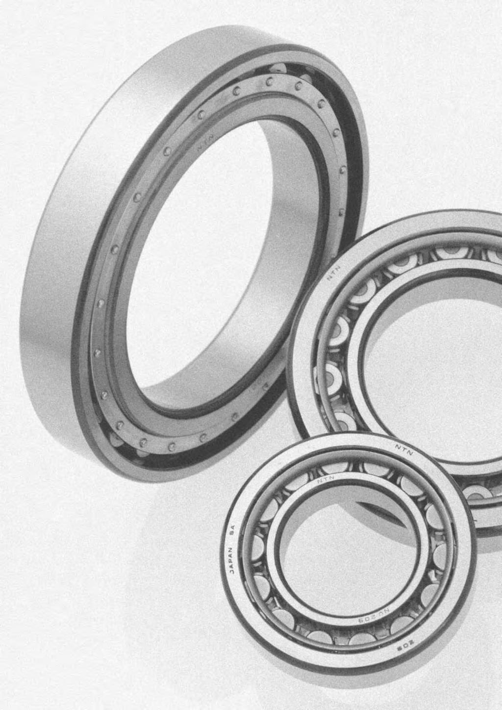
183


184 Cylindical Rolle Beaings Cylindical olle beaing E Type cylindical olle beaing Double ow cylindical olle beaing Fou ow cylindical olle beaing 1. Types, design featues, and chaacteistics Since the olling elements in cylindical olle beaings make line contact with aceways, these beaings can accommodate heavy adial loads. The olles ae guided by ibs on eithe the inne o oute ing, theefoe these beaings ae also suitable fo high speed applications. Futhemoe, cylindical olle beaings ae sepaable, and elatively easy to install and disassemble even when intefeence fits ae equied. Among the vaious types of cylindical olle beaings, Type E has a high load capacity and its bounday dimensions ae identical to standad type. HT type has a lage axial load capacity, and HL type povides extended wea life in conditions whee the development of a lubicating film inside the beaing is difficult. Double and multiple ow beaing aangements ae also available. Fo extemely heavy load applications, the non-sepaable full complement SL type beaing offes special advantages. Table 1 shows the vaious types and chaacteistics of single ow cylindical olle beaings. Table 2 shows the chaacteistics of non-standad type cylindical olle beaings. Table 1 Cylindical olle beaing types and chaacteistics Type code Design Chaacteistics NU type N type NU type NU type oute ings have double ibs; oute ing and olle as well as cage can be sepaated fom inne ing. N type inne ing have double ibs; inne ing and olle as well as cage can be sepaated fom oute ing. Unable to accommodate even the lightest axial loads. This type is extemely suitable fo, and widely used as, the floating side beaing. N type NJ type NF type NJ type NJ type has double ibs on oute ing, single ib on inne ing; NF type has single ib on oute ing, and double ib on inne ing. Can eceive single diection axial loads. When thee is no distinction between the fixed side and floating side beaing, can be used as a pai in close poximity. NF type NUP type NH type (NJ + HJ) NUP type NUP type has a colla ing attached to the ibless side of the inne ing; NH type is NJ type with an L type colla ing attached. All of these colla ings ae sepaable, and theefoe it is necessay to fix the inne ing axially. Can accommodate axial loads in eithe diection. Widely used as the shaft's fixed-side beaing. NH type B-77
185 Cylindical Rolle Beaings Table 2 Non-standad type cylindical olle beaing chaacteistics Beaing type Chaacteistics Bounday dimensions ae the same as the standad type, but the diamete, length and numbe of the olles have been inceased, as well as load capacity. Identified by addition of "E" to end of basic olle numbe. Enables compact design due to its high load ating. Rolles' inscibed cicle diamete diffes fom standad type olles and theefoe cannot be intechanged. E Type cylindical olle beaing 18mm 1mm 215mm 12mm E type Standad type NU222E C=335kN E type beaing NU32 C=299kN Standad type beaing NU224E C=335kN E type beaing Remaks: In the dimension tables, both E type and standad type ae listed, but in the futue JIS will change to E type. Lage axial load use cylindical olle beaings (HT type) Double ow cylindical olle beaings Fou ow cylindical olle beaings SL type cylindical olle beaings Can accommodate lage axial loads than standad type thanks to impoved geomety of the ib olle end suface. Please consult NTN Engineeing concening the many factos which equie consideation, such as load, lubicant, and installation conditions. NN type and NNU type available. Widely used fo applications equiing thin-walled beaings, such the main shafts of machine tools, olling machine olles, and in pinting equipment. Intenal adial cleaance is adjusted fo the spindle of machine tools by pessing the tapeed boe of the inne ing on a tapeed shaft. Used mainly in the necks of olling machine olles; designed fo maximum ated load to accommodate the seveely limited space in the olle neck section of such equipment. Many vaieties exist, including sealed types, which have been specially designed fo high speed use, to pevent ceeping, povide dust and wate poofing popeties, etc. Contact NTN Engineeing. Full complement olle beaing capable of handling heavy loads. Consult NTN Engineeing egading special application designs fo SL type cylindical olle beaings. 2. Standad cage types Table 3 shows the standad vaieties fo cylindical olle beaings. Table 3 Standad cage types The basic oad atings listed in the dimension chats coespond to values achieved with the standad cages listed in Table 3. Futhemoe, please note that even fo the identical beaing, in cases whee the numbe of olling elements o the cage type diffes, the basic ated load will also diffe fom the values listed in the dimension chats. Beaing seies Molded esin cage Pessed cage Machined cage NU1 NU 2 NU2E NU22 NU22E NU3 NU3E NU23 NU23E NU4 24E218E 224E2218E 34E314E 234E2311E / E24E E224E E332E E2332E Note: 1) Within the same beaing seies, cage type is identical even if the type code (NJ, NUP, N, NF) diffes. 2) Fo high speed and othe special applications, machined cages can be manufactued when necessay. Consult NTN Engineeing. 3) Among E type beaings (those using molded esin cages), cetain vaieties may also use pessed cages. Consult NTN Engineeing. 4) Although machined cages ae standad fo two ow and fou ow cylindical olle beaings, molded esin cages may also be used in some of these beaings fo machine tool applications. 5) Due to thei mateial popeties, molded esin cages cannot be used in applications whee tempeatues exceed 12 C. #4 - #7 howeve use esin mateial with supeio ability to withstand heat and high tempeatues, which ae capable of withstanding tempeatues up to 15 C. 6) Fomed esin cages capable of withstanding tempeatues up to 15 C can be manufactued by equest fo type E (fomed esin cage) of #8 o geate. Fo infomation, please contact NTN Engineeing. B-78
186 Cylindical Rolle Beaings 3. Allowable misalignment Although values vay somewhat depending on beaing type and intenal specifications, unde geneal load conditions, to avoid the occuence of edge loading, allowable misalignments have been set as follows: ae to suppot an axial load o moment load simultaneously, please contact NTN Engineeing. NTN Engineeing also offes cylindical olle beaings fo high axial loads (HT type). Fo details, please contact NTN Engineeing. Beaing width seies o 1:.1 ad (3.5') Beaing width seies 2:.5 ad (1.5') Double ow cylindical olle beaings 1 :.5 ad (1.5') 1 Does not include high pecision beaings fo machine tool main shaft applications. 4. Allowable axial load fo cylindical olle beaings Cylindical olle beaings with ibs on the inne and oute ings ae capable of simultaneously beaing a adial load and an axial load of a cetain degee. Unlike basic oad atings based on olling fatigue, allowable axial load is detemined by heat poduced on the sliding suface between the ends of the olles and ib, seizue and wea. Allowable axial load when cente axial load is applied is appoximately detemined by fomula (1), which is based upon expeience and testing. Allowable suface pessue Pz MPa Gease o oil lubication Momentay axial load Intemittent axial load Constant axial load Pimaily oil lubication Gease lubication dpn 1 4 mmmin -1 dprolle pitch diamete mm dp(beaing boe + beaing outside diamete)/2 mm nrotational speed min -1 Fig. 1 Allowable suface pessue of ib Pt = k d 2 Pz (1) Whee: Pt : Allowable axial load when otating N {kgf} k : Facto detemined by intenal design of beaing (see Table 4) d : Beaing boe mm Pz : Allowable suface pessue of ib MPa {kgf/mm 2 } (see Fig. 1) If axial load is geate than adial load, the olles will not otate popely. The allowable axial load theefoe must not exceed the value fo Fa max given in Table 4. The following ae also impotant to opeate the beaing smoothly unde axial load: (1) Do not make the intenal adial cleaance any lage than necessay. (2) Use lubicant with exteme pessue additive. (3) Make the shoulde of the housing and shaft high enough fo the ib of the beaing. (4) If the beaing is to suppot an exteme axial load, mounting pecision should be impoved and the beaing should otate slowly befoe actual use. If lage cylindical olle beaings (boe of 3 mm o moe) Table 4 Facto k values and allowable axial load (Fa max) Beaing seies k Fa max NJ, NUP1 NJ, NUP, NF, NH2, NJ, NUP, NH22 NJ, NUP, NF, NH3, NJ, NUP, NH23 NJ, NUP, NH2E, NJ, NUP, NH22E NJ, NUP, NH3E, NJ, NUP, NH23E NJ, NUP, NH4, SL1-48 SL SL F.4F.4F.4F.4F.2F.2F.2F B-79
187 Cylindical Rolle Beaings B B D d FW J J D EW d J Type NU Type NJ Type NUP Type N Type NF d 2 4mm Bounday dimensions Basic load atings Limiting speeds 1) Beaing numbes 2) dynamic static dynamic static mm kn kgf min -1 type type type type d D B s min 3) 1s min 3) C C o C C o gease oil NU NJ NUP N NU24E NJ NUP NU224E NJ NUP NU34E NJ NUP NU234E NJ NUP NU15 NJ NUP N NU25E NJ NUP NU225E NJ NUP NU35E NJ NUP NU235E NJ NUP NU45 NJ NUP N NU16 NJ NUP N NU26E NJ NUP NU226E NJ NUP NU36E NJ NUP NU236E NJ NUP NU46 NJ NUP N NU17 NJ NUP N NU27E NJ NUP NU227E NJ NUP NU37E NJ NUP NU237E NJ NUP NU47 NJ NUP N NU18 NJ NUP N NU28 NJ NUP N NU28E NJ NUP NU228 NJ NUP N NU228E NJ NUP NU38 NJ NUP N NU38E NJ NUP NU238 NJ NUP N NU238E NJ NUP NU48 NJ NUP N 1)This value achieved with machined cages; when pessed cages ae used, 8% of this value is acceptable. 2)Poduction switched to E type only fo beaing numbe fo which thee is no standad fom. 3)Minimal allowable dimension fo chamfe dimension o 1. B-8
188 Cylindical Rolle Beaings a 1a 1a a Da dc da dd dc de Db db Db Dynamic equivalent adial load P=F Static equivalent adial load Po=F Dimensions Abutment and fillet dimensions Mass mm mm kg type d a d b d c d d d e D a D b as 1as type NU type N NF F w E w J min min max min min max max min 4) max max (appox.) NF NF NF NF NF NF )Does not apply to side of the oute ing ib of type NF beaings. B-81
189 Cylindical Rolle Beaings B B D d FW J J D EW d J Type NU Type NJ Type NUP Type N Type NF d 45 6mm Bounday dimensions Basic load atings Limiting speeds 1) Beaing numbes 2) dynamic static dynamic static mm kn kgf min -1 type type type type d D B s min 3) 1s min 3) C C o C C o gease oil NU NJ NUP N NU19 NJ NUP N NU29 NJ NUP N NU29E NJ NUP NU229 NJ NUP N NU229E NJ NUP NU39 NJ NUP N NU39E NJ NUP NU239 NJ NUP N NU239E NJ NUP NU49 NJ NUP N NU11 NJ NUP N NU21 NJ NUP N NU21E NJ NUP NU221 NJ NUP N NU221E NJ NUP NU31 NJ NUP N NU31E NJ NUP NU231 NJ NUP N NU231E NJ NUP NU41 NJ NUP N NU111 NJ NUP N NU211 NJ NUP N NU211E NJ NUP NU2211 NJ NUP N NU2211E NJ NUP NU311 NJ NUP N NU311E NJ NUP NU2311 NJ NUP N NU2311E NJ NUP NU411 NJ NUP N NU112 NJ NUP N NU212 NJ NUP N NU212E NJ NUP NU2212 NJ NUP N 1)This value achieved with machined cages; when pessed cages ae used, 8% of this value is acceptable. 2)Poduction switched to E type only fo beaing numbe fo which thee is no standad fom. 3)Minimal allowable dimension fo chamfe dimension o 1. B-82
190 Cylindical Rolle Beaings a 1a 1a a Da dc da dd dc de Db db Db Dynamic equivalent adial load P=F Static equivalent adial load Po=F Dimensions Abutment and fillet dimensions Mass mm mm kg type d a d b d c d d d e D a D b as 1as type NU type N NF F w E w J min min max min min max max min 4) max max (appox.) NF NF NF NF NF NF NF NF NF NF )Does not apply to side of the oute ing ib of type NF beaings. B-83
191 Cylindical Rolle Beaings B B D d FW J J D EW d J Type NU Type NJ Type NUP Type N Type NF d 6 75mm Bounday dimensions Basic load atings Limiting speeds 1) Beaing numbes 2) dynamic static dynamic static mm kn kgf min -1 type type type type d D B s min 3) 1s min 3) C C o C C o gease oil NU NJ NUP N NU2212E NJ NUP NU312 NJ NUP N NU312E NJ NUP NU2312 NJ NUP N NU2312E NJ NUP NU412 NJ NUP N NU113 NJ NUP N NU213 NJ NUP N NU213E NJ NUP NU2213 NJ NUP N NU2213E NJ NUP NU313 NJ NUP N NU313E NJ NUP NU2313 NJ NUP N NU2313E NJ NUP NU413 NJ NUP N NU114 NJ NUP N NU214 NJ NUP N NU214E NJ NUP NU2214 NJ NUP N NU2214E NJ NUP NU314 NJ NUP N NU314E NJ NUP NU2314 NJ NUP N NU2314E NJ NUP NU414 NJ NUP N NU115 NJ NUP N NU215 NJ NUP N NU215E NJ NUP NU2215 NJ NUP N NU2215E NJ NUP NU315 NJ NUP N NU315E NJ NUP NU2315 NJ NUP N 1)This value achieved with machined cages; when pessed cages ae used, 8% of this value is acceptable. 2)Poduction switched to E type only fo beaing numbe fo which thee is no standad fom. 3)Minimal allowable dimension fo chamfe dimension o 1. B-84
192 Cylindical Rolle Beaings a 1a 1a a Da dc da dd dc de Db db Db Dynamic equivalent adial load P=F Static equivalent adial load Po=F Dimensions Abutment and fillet dimensions Mass mm mm kg type d a d b d c d d d e D a D b as 1as type NU type N NF F w E w J min min max min min max max min 4) max max (appox.) NF NF NF NF NF NF NF NF NF NF )Does not apply to side of the oute ing ib of type NF beaings. B-85
193 Cylindical Rolle Beaings B B D d FW J J D EW d J Type NU Type NJ Type NUP Type N Type NF d 75 95mm Bounday dimensions Basic load atings Limiting speeds 1) Beaing numbes 2) dynamic static dynamic static mm kn kgf min -1 type type type type d D B s min 3) 1s min 3) C C o C C o gease oil NU NJ NUP N NU2315E NJ NUP NU415 NJ NUP N NU116 NJ NUP N NU216 NJ NUP N NU216E NJ NUP NU2216 NJ NUP N NU2216E NJ NUP NU316 NJ NUP N NU316E NJ NUP NU2316 NJ NUP N NU2316E NJ NUP NU416 NJ NUP N NU117 NJ NUP N NU217 NJ NUP N NU217E NJ NUP NU2217 NJ NUP N NU2217E NJ NUP NU317 NJ NUP N NU317E NJ NUP NU2317 NJ NUP N NU2317E NJ NUP NU118 NJ NUP N NU218 NJ NUP N NU218E NJ NUP NU2218 NJ NUP N NU2218E NJ NUP NU318 NJ NUP N NU318E NJ NUP NU2318 NJ NUP N NU2318E NJ NUP NU119 NJ NUP N NU219 NJ NUP N NU219E NJ NUP 1)This value achieved with machined cages; when pessed cages ae used, 8% of this value is acceptable. 2)Poduction switched to E type only fo beaing numbe fo which thee is no standad fom. 3)Minimal allowable dimension fo chamfe dimension o 1. B-86
194 Cylindical Rolle Beaings a 1a 1a a Da dc da dd dc de Db db Db Dynamic equivalent adial load P=F Static equivalent adial load Po=F Dimensions Abutment and fillet dimensions Mass mm mm kg type d a d b d c d d d e D a D b as 1as type NU type N NF F w E w J min min max min min max max min 4) max max (appox.) NF NF NF NF NF NF NF NF NF )Does not apply to side of the oute ing ib of type NF beaings. B-87
195 Cylindical Rolle Beaings B B D d FW J J D EW d J Type NU Type NJ Type NUP Type N Type NF d 95 12mm Bounday dimensions Basic load atings Limiting speeds 1) Beaing numbes 2) dynamic static dynamic static mm kn kgf min -1 type type type type d D B s min 3) 1s min 3) C C o C C o gease oil NU NJ NUP N NU2219 NJ NUP N NU2219E NJ NUP NU319 NJ NUP N NU319E NJ NUP NU2319 NJ NUP N NU2319E NJ NUP NU12 NJ NUP N NU22 NJ NUP N NU22E NJ NUP NU222 NJ NUP N NU222E NJ NUP NU32 NJ NUP N NU32E NJ NUP NU232 NJ NUP N NU232E NJ NUP NU121 NJ NUP N NU221 NJ NUP N NU321 NJ NUP N NU122 NJ NUP N NU222 NJ NUP N NU222E NJ NUP NU2222 NJ NUP N NU2222E NJ NUP NU322 NJ NUP N NU322E NJ NUP NU2322 NJ NUP N NU2322E NJ NUP NU124 NJ NUP N NU224 NJ NUP N NU224E NJ NUP NU2224 NJ NUP N NU2224E NJ NUP NU324 NJ NUP N 1)This value achieved with machined cages; when pessed cages ae used, 8% of this value is acceptable. 2)Poduction switched to E type only fo beaing numbe fo which thee is no standad fom. 3)Minimal allowable dimension fo chamfe dimension o 1. B-88
196 Cylindical Rolle Beaings a 1a 1a a Da dc da dd dc de Db db Db Dynamic equivalent adial load P=F Static equivalent adial load Po=F Dimensions Abutment and fillet dimensions Mass mm mm kg type d a d b d c d d d e D a D b as 1as type NU type N NF F w E w J min min max min min max max min 4) max max (appox.) NF NF NF NF NF NF NF NF NF )Does not apply to side of the oute ing ib of type NF beaings. B-89
197 Cylindical Rolle Beaings B B D d FW J J D EW d J Type NU Type NJ Type NUP Type N Type NF d 12 16mm Bounday dimensions Basic load atings Limiting speeds 1) Beaing numbes 2) dynamic static dynamic static mm kn kgf min -1 type type type type d D B s min 3) 1s min 3) C C o C C o gease oil NU NJ NUP N NU324E NJ NUP NU2324 NJ NUP N NU2324E NJ NUP NU126 NJ NUP N NU226 NJ NUP N NU226E NJ NUP NU2226 NJ NUP N NU2226E NJ NUP NU326 NJ NUP N NU326E NJ NUP NU2326 NJ NUP N NU2326E NJ NUP NU128 NJ NUP N NU228 NJ NUP N NU228E NJ NUP NU2228 NJ NUP N NU2228E NJ NUP NU328 NJ NUP N NU328E NJ NUP NU2328 NJ NUP N NU2328E NJ NUP NU13 NJ NUP N NU23 NJ NUP N NU23E NJ NUP NU223 NJ NUP N NU223E NJ NUP NU33 NJ NUP N NU33E NJ NUP NU233 NJ NUP N NU233E NJ NUP NU132 NJ NUP N NU232 NJ NUP N NU232E NJ NUP 1)This value achieved with machined cages; when pessed cages ae used, 8% of this value is acceptable. 2)Poduction switched to E type only fo beaing numbe fo which thee is no standad fom. 3)Minimal allowable dimension fo chamfe dimension o 1. B-9
198 Cylindical Rolle Beaings a 1a 1a a Da dc da dd dc de Db db Db Dynamic equivalent adial load P=F Static equivalent adial load Po=F Dimensions Abutment and fillet dimensions Mass mm mm kg type d a d b d c d d d e D a D b as 1as type NU type N NF F w E w J min min max min min max max min 4) max max (appox.) NF NF NF NF NF NF NF )Does not apply to side of the oute ing ib of type NF beaings. B-91
199 Cylindical Rolle Beaings B B D d FW J J D EW d J Type NU Type NJ Type NUP Type N Type NF d 16 2mm Bounday dimensions Basic load atings Limiting speeds 1) Beaing numbes 2) dynamic static dynamic static mm kn kgf min -1 type type type type d D B s min 3) 1s min 3) C C o C C o gease oil NU NJ NUP N NU2232 NJ NUP N NU2232E NJ NUP NU332 NJ NUP N NU332E NJ NUP NU2332 NJ NUP N NU2332E NJ NUP NU134 NJ NUP N NU234 NJ NUP N NU234E NJ NUP NU2234 NJ NUP N NU2234E NJ NUP NU334 NJ NUP N NU2334 NJ NUP N NU136 NJ NUP N NU236 NJ NUP N NU236E NJ NUP NU2236 NJ NUP N NU2236E NJ NUP NU336 NJ NUP N NU2336 NJ NUP N NU138 NJ NUP N NU238 NJ NUP N NU238E NJ NUP NU2238 NJ NUP N NU2238E NJ NUP NU338 NJ NUP N NU2338 NJ NUP N NU14 NJ NUP N NU24 NJ NUP N NU24E NJ NUP NU224 NJ NUP N NU224E NJ NUP NU34 NJ NUP N 1)This value achieved with machined cages; when pessed cages ae used, 8% of this value is acceptable. 2)Poduction switched to E type only fo beaing numbe fo which thee is no standad fom. 3)Minimal allowable dimension fo chamfe dimension o 1. B-92
200 Cylindical Rolle Beaings a 1a 1a a Da dc da dd dc de Db db Db Dynamic equivalent adial load P=F Static equivalent adial load Po=F Dimensions Abutment and fillet dimensions Mass mm mm kg type d a d b d c d d d e D a D b as 1as type NU type N NF F w E w J min min max min min max max min 4) max max (appox.) NF NF NF NF NF NF NF NF NF )Does not apply to side of the oute ing ib of type NF beaings. B-93
201 Cylindical Rolle Beaings B B D d FW J J D EW d J Type NU Type NJ Type NUP Type N Type NF d 2 36mm Bounday dimensions Basic load atings Limiting speeds 1) Beaing numbes 2) dynamic static dynamic static mm kn kgf min -1 type type type type d D B s min 3) 1s min 3) C C o C C o gease oil NU NJ NUP N NU234 NJ NUP N NU144 NJ NUP N NU244 NJ NUP N NU2244 NJ NUP N NU344 NJ NUP N NU2344 NJ NUP N NU148 NJ NUP N NU248 NJ NUP N NU2248 NJ NUP N NU348 NJ NUP N NU2348 NJ NUP N NU152 NJ NUP N NU252 NJ NUP N NU2252 NJ NUP N NU352 NJ NUP N NU2352 NJ NUP N NU156 NJ NUP N NU256 NJ NUP N NU2256 NJ NUP N NU356 NJ NUP N NU2356 NJ NUP N NU16 NJ NUP N NU26 NJ NUP N NU226 NJ NUP N NU164 NJ NUP N NU264 NJ NUP N NU2264 NJ NUP N NU168 NJ NUP N NU172 NJ NUP N 1)This value achieved with machined cages; when pessed cages ae used, 8% of this value is acceptable. 2)Poduction switched to E type only fo beaing numbe fo which thee is no standad fom. 3)Minimal allowable dimension fo chamfe dimension o 1. B-94
202 Cylindical Rolle Beaings a 1a 1a a Da dc da dd dc de Db db Db Dynamic equivalent adial load P=F Static equivalent adial load Po=F Dimensions Abutment and fillet dimensions Mass mm mm kg type d a d b d c d d d e D a D b as 1as type NU type N NF F w E w J min min max min min max max min 4) max max (appox.) NF NF NF NF NF NF NF NF NF NF )Does not apply to side of the oute ing ib of type NF beaings. B-95
203 Cylindical Rolle Beaings B B D d FW J J D EW d J Type NU Type NJ Type NUP Type N Type NF d 38 5mm Bounday dimensions Basic load atings Limiting speeds 1) Beaing numbes 2) dynamic static dynamic static mm kn kgf min -1 type type type type d D B s min 3) 1s min 3) C C o C C o gease oil NU NJ NUP N NU176 NJ NUP N NU18 NJ NUP N NU184 NJ NUP N NU188 NJ NUP N NU192 NJ NUP N NU196 NJ NUP N NU1/5 NJ NUP N 1)This value achieved with machined cages; when pessed cages ae used, 8% of this value is acceptable. 2)Poduction switched to E type only fo beaing numbe fo which thee is no standad fom. 3)Minimal allowable dimension fo chamfe dimension o 1. B-96
204 Cylindical Rolle Beaings a 1a 1a a Da dc da dd dc de Db db Db Dynamic equivalent adial load P=F Static equivalent adial load Po=F Dimensions Abutment and fillet dimensions Mass mm mm kg type d a d b d c d d d e D a D b as 1as type NU type N NF F w E w J min min max min min max max min 4) max max (appox.) )Does not apply to side of the oute ing ib of type NF beaings. B-97
205 L Type Loose Rib L type colla ing B2 B2 1 1 B1 d d1 B1 d d1 NH=NJ+HJ NUJ=NU+HJ d 2 6mm Dimensions Beaing Mass numbes mm kg Dimensions Beaing Mass numbes mm kg d d 1 B 1 B 2 1s min 1) (appox.) d d 1 B 1 B 2 1s min 1) (appox.) HJ HJ24E HJ HJ224E HJ HJ34E HJ HJ234E HJ HJ25E HJ HJ225E HJ HJ35E HJ HJ235E HJ HJ HJ28E HJ HJ228E HJ HJ38E HJ HJ238E HJ * HJ HJ29E HJ229E HJ HJ39E HJ HJ239E HJ HJ HJ26E HJ HJ226E HJ HJ36E HJ HJ236E HJ HJ HJ27E HJ HJ227E HJ HJ37E HJ HJ237E HJ )Minimal allowable dimension fo chamfe dimension. Note: 1. This L type colla ing is used with NU type cylindical olle beaings; in duplex aangements with NJ o NU type beaing numbes, they become NH type and NUJ type espectively. Fo beaing dimensions, allowable otations, and mass, please efe to pages B-94 to B " * " indicates L type colla ings that can also be used with dimension seies 22 beaings. B HJ * HJ21E HJ HJ HJ31E HJ HJ231E HJ * HJ HJ211E HJ2211E HJ HJ311E HJ HJ2311E HJ * HJ * HJ212E.94
206 L Type Loose Rib B2 B2 1 1 B1 d d1 B1 d d1 NH=NJ+HJ NUJ=NU+HJ d 6 15mm Dimensions Beaing Mass numbes mm kg Dimensions Beaing Mass numbes mm kg d d 1 B 1 B 2 1s min 1) (appox.) d d 1 B 1 B 2 1s min 1) (appox.) HJ HJ312E HJ HJ2312E HJ HJ HJ213E HJ HJ2213E HJ HJ313E HJ HJ2313E HJ * HJ HJ214E HJ2214E HJ HJ314E HJ HJ2314E HJ * HJ HJ215E HJ2215E HJ HJ315E HJ HJ2315E HJ * HJ * HJ216E HJ HJ316E HJ )Minimal allowable dimension fo chamfe dimension. Note: 1. This L type colla ing is used with NU type cylindical olle beaings; in duplex aangements with NJ o NU type beaing numbes, they become NH type and NUJ type espectively. Fo beaing dimensions, allowable otations, and mass, please efe to pages B-98 to B " * " indicates L type colla ings that can also be used with dimension seies 22 beaings. B HJ2316E HJ * HJ HJ217E HJ2217E HJ HJ317E HJ HJ2317E HJ HJ218E HJ HJ2218E HJ HJ318E HJ HJ2318E HJ HJ219E HJ HJ2219E HJ HJ319E HJ HJ2319E HJ HJ22E HJ HJ222E HJ HJ32E HJ HJ232E HJ221.55
207 L Type Loose Rib L type colla ing B2 B2 1 1 B1 d d1 B1 d d1 NH=NJ+HJ NUJ=NU+HJ d 15 2mm Dimensions Beaing Mass numbes mm kg Dimensions Beaing Mass numbes mm kg d d 1 B 1 B 2 1s min 1) (appox.) d d 1 B 1 B 2 1s min 1) (appox.) HJ HJ HJ222E HJ HJ2222E HJ HJ322E HJ HJ2322E HJ HJ224E HJ HJ2224E HJ HJ324E HJ HJ2324E HJ HJ226E HJ HJ2226E HJ HJ326E HJ HJ2326E HJ HJ228E HJ HJ2228E HJ HJ328E HJ HJ2328E HJ23E HJ HJ223E HJ HJ33E HJ HJ233E HJ HJ232E HJ HJ2232E HJ HJ332E HJ HJ2332E HJ HJ234E HJ HJ2234E HJ HJ HJ HJ236E HJ HJ2236E HJ HJ HJ HJ238E HJ HJ2238E HJ HJ HJ )Minimal allowable dimension fo chamfe dimension. Note: 1. This L type colla ing is used with NU type cylindical olle beaings; in duplex aangements with NJ o NU type beaing numbes, they become NH type and NUJ type espectively. Fo beaing dimensions, allowable otations, and mass, please efe to pages B-12 to B " * " indicates L type colla ings that can also be used with dimension seies 22 beaings. B HJ24 2.6
208 L Type Loose Rib B2 B2 1 1 B1 d d1 B1 d d1 NH=NJ+HJ NUJ=NU+HJ d 2 32mm Dimensions Beaing Mass numbes mm kg d d 1 B 1 B 2 1s min 1) (appox.) HJ24E HJ HJ224E HJ HJ HJ HJ HJ HJ HJ HJ HJ HJ HJ HJ )Minimal allowable dimension fo chamfe dimension. Note: 1. This L type colla ing is used with NU type cylindical olle beaings; in duplex aangements with NJ o NU type beaing numbes, they become NH type and NUJ type espectively. Fo beaing dimensions, allowable otations, and mass, please efe to pages B-18 to B " * " indicates L type colla ings that can also be used with dimension seies 22 beaings. B-11
209 Double Row Cylindical Rolle Beaings B B D d FW d D Ew d d Type NNU Cylindical boe Tapeed boe Type NN Cylindical boe Tapeed boe d 25 11mm Bounday dimensions Basic load atings Limiting speeds Beaing dynamic static dynamic static mm kn kgf min -1 type NNU cylindical tapeed 1) d D B 2) s min C C o C C o gease oil boe boe NNU492 NNU492K NNU4921 NNU4921K NNU4922 NNU4922K )"K" indicates beaings have tapeed boe with a tape atio of 1: 12. 2)Smallest allowable dimension fo chamfe dimension. B-12
210 Double Row Cylindical Rolle Beaings a a a a a Da dc da dd Db da Db Db da db Dynamic equivalent adial load P=F Static equivalent adial load Po=F numbes Dimensions Abutment and fillet dimensions Mass (appox.) kg type NN mm mm type NNU type NN cylindical tapeed 1) d a d b d c d d D a D b as cylindical tapeed cylindical tapeed boe boe F w E w min min max min max max min max boe boe boe boe NN35 NN35K NN36 NN36K NN37 NN37K NN38 NN38K NN39 NN39K NN31 NN31K NN311 NN311K NN312 NN312K NN313 NN313K NN314 NN314K NN315 NN315K NN316 NN316K NN317 NN317K NN318 NN318K NN319 NN319K NN492 NN492K NN32 NN32K NN4921 NN4921K NN321 NN321K NN4922 NN4922K NN322 NN322K B-13
211 Double Row Cylindical Rolle Beaings B B D d FW d D Ew d d Type NNU Cylindical boe Tapeed boe Type NN Cylindical boe Tapeed boe d 12 28mm Bounday dimensions Basic load atings Limiting speeds Beaing dynamic static dynamic static mm kn kgf min -1 type NNU cylindical tapeed 1) d D B 2) s min C C o C C o gease oil boe boe NNU4924 NNU4924K NNU4926 NNU4926K NNU4928 NNU4928K NNU493 NNU493K NNU4932 NNU4932K NNU4934 NNU4934K NNU4936 NNU4936K NNU4938 NNU4938K NNU494 NNU494K NNU4944 NNU4944K NNU4948 NNU4948K NNU4952 NNU4952K NNU4956 NNU4956K )"K" indicates beaings have tapeed boe with a tape atio of 1: 12. 2)Smallest allowable dimension fo chamfe dimension. B-14
212 Double Row Cylindical Rolle Beaings a a a a a Da dc da dd Db da Db Db da db Dynamic equivalent adial load P=F Static equivalent adial load Po=F numbes Dimensions Abutment and fillet dimensions Mass (appox.) kg type NN mm mm type NNU type NN cylindical tapeed 1) d a d b d c d d D a D b as cylindical tapeed cylindical tapeed boe boe F w E w min min max min max max min max boe boe boe boe NN4924 NN4924K NN324 NN324K NN4926 NN4926K NN326 NN326K NN4928 NN4928K NN328 NN328K NN493 NN493K NN33 NN33K NN4932 NN4932K NN332 NN332K NN4934 NN4934K NN334 NN334K NN4936 NN4936K NN336 NN336K NN4938 NN4938K NN338 NN338K NN494 NN494K NN34 NN34K NN4944 NN4944K NN344 NN344K NN4948 NN4948K NN348 NN348K NN4952 NN4952K NN352 NN352K NN4956 NN4956K NN356 NN356K B-15
213 Double Row Cylindical Rolle Beaings B B D d FW d D Ew d d Cylindical boe Type NNU Tapeed boe Cylindical boe Type NN Tapeed boe d 3 5mm Bounday dimensions Basic load atings Limiting speeds Beaing dynamic static dynamic static mm kn kgf min -1 type NNU cylindical tapeed 1) d D B 2) s min C C o C C o gease oil boe boe NNU496 NNU496K NNU4964 NNU4964K NNU4968 NNU4968K NNU4972 NNU4972K NNU4976 NNU4976K NNU498 NNU498K NNU4984 NNU4984K NNU4988 NNU4988K NNU4992 NNU4992K NNU4996 NNU4996K NNU49/5 NNU49/5K 1)"K" indicates beaings have tapeed boe with a tape atio of 1: 12. 2)Smallest allowable dimension fo chamfe dimension. B-16
214 Double Row Cylindical Rolle Beaings a a a a a Da dc da dd Db da Db Db da db Dynamic equivalent adial load P=F Static equivalent adial load Po=F numbes Dimensions Abutment and fillet dimensions Mass (appox.) kg type NN mm mm type NNU type NN cylindical tapeed 1) d a d b d c d d D a D b as cylindical tapeed cylindical tapeed boe boe F w E w min min max min max max min max boe boe boe boe NN496 NN496K NN36 NN36K NN4964 NN4964K NN364 NN364K NN368 NN368K NN372 NN372K NN376 NN376K NN38 NN38K NN384 NN384K NN388 NN388K NN392 NN392K B-17
215 Fou-Row Cylindical Rolle Beaings C1 1 B1 D d FW Dawing 1 d 12 2mm Bounday dimensions Basic load atings dynamic static dynamic static mm kn kgf d D B 1 C 1 s min 1) 1s min 1) C C o C C o )Minimal allowable dimension fo chamfe dimension o 1. 2)An oil hole and goove ae povided in the cente of the oute ing. The oil goove is not povided on the side. B-18
216 Fou-Row Cylindical Rolle Beaings Beaing numbes Dimensions Dawing Mass no. kg F w (appox.) 4R R R R R R R R R R R R R R R R R R R R R R R R R R R R ) R R R Note: Dawing 1 epesents a beaing with solid olles and machined cage. B-19
217 Fou-Row Cylindical Rolle Beaings C1 C1 1 1 B1 B1 D d FW D d FW Dawing 1 Dawing 2 d 2 3mm Bounday dimensions Basic load atings dynamic static dynamic static mm kn kgf d D B 1 C 1 s min 1) 1s min 1) C C o C C o )Minimal allowable dimension fo chamfe dimension o 1. 2)An oil hole and goove ae povided in the cente of the oute ing. 3)An oil hole and goove ae not povided on the oute ing space. B-11
218 Fou-Row Cylindical Rolle Beaings Beaing numbes Dimensions Dawing Mass no. kg F w (appox.) 4R R R R R R R R R R R R R R R ) R R R R R R ) 15 4R R R R R E-4R E-4R E-4R E-4R Note: Dawing 1 epesents a beaing with solid olles and machined cage; Dawing 2 epesents a beaing with hollow olles and pin type cage. B-111
219 Fou-Row Cylindical Rolle Beaings C1 C1 1 1 B1 B1 D d FW D d FW Dawing 1 Dawing 2 d 3 46mm Bounday dimensions Basic load atings dynamic static dynamic static mm kn kgf d D B 1 C 1 s min 1) 1s min 1) C C o C C o )Minimal allowable dimension fo chamfe dimension o 1. 2)Oil inlet and oil goove ae in cente of the oute ing; no oil goove on the side. 3)Oil inlet in space of oute ing; no oil goove. 4)One-piece inne ing. B-112
220 Fou-Row Cylindical Rolle Beaings Beaing numbes Dimensions Dawing Mass no. kg F w (appox.) E-4R E-4R E-4R E-4R E-4R E-4R E-4R E-4R ) 83.6 E-4R E-4R E-4R E-4R ) 262 E-4R E-4R E-4R E-4R ) 21 E-4R ) 325 E-4R E-4R E-4R ) 256 E-4R E-4R E-4R E-4R E-4R )4) 383 E-4R E-4R Note: Dawing 1 epesents a beaing with solid olles and machined cage; Dawing 2 epesents a beaing with hollow olles and pin type cage. B-113
221 Fou-Row Cylindical Rolle Beaings C1 C1 1 1 B1 B1 D d FW D d FW Dawing 1 Dawing 2 d 48 69mm Bounday dimensions Basic load atings dynamic static dynamic static mm kn kgf d D B 1 C 1 s min 1) 1s min 1) C C o C C o X X )Minimal allowable dimension fo chamfe dimension o 1. 2)Oil inlet and oil goove ae in cente of the oute ing; no oil goove on the side. 3)Oil inlet in space of oute ing; no oil goove. B-114
222 Fou-Row Cylindical Rolle Beaings Beaing numbes Dimensions Dawing Mass no. kg F w (appox.) E-4R ) 369 E-4R ) 395 E-4R E-4R ) 495 E-4R E-4R E-4R E-4R E-4R E-4R ) 335 E-4R E-4R E-4R E-4R E-4R E-4R E-4R E-4R E-4R E-4R E-4R E-4R E-4R ) 1 4 E-4R E-4R E-4R E-4R )One-piece inne ing. Note: Dawing 1 epesents a beaing with solid olles and machined cage; Dawing 2 epesents a beaing with hollow olles and pin type cage. B-115
223 Fou-Row Cylindical Rolle Beaings C1 C1 1 1 B1 B1 D d FW D d FW Dawing 1 Dawing 2 d 7 1 2mm Bounday dimensions Basic load atings dynamic static dynamic static mm kn kgf d D B 1 C 1 s min 1) 1s min 1) C C o C C o X )Minimal allowable dimension fo chamfe dimension o 1. 2)Inne ing is divided into fou. 3)The oil hole of the oute ing is povided with fitting nozzle fo oil mist. B-116
224 Fou-Row Cylindical Rolle Beaings Beaing numbes Dimensions Dawing Mass no. kg F w (appox.) E-4R E-4R ) 1 9 E-4R E-4R ) 2 18 E-4R ) 2 53 E-4R ) 2 E-4R ) 2 55 E-4R ) 2 56 E-4R E-4R E-4R ) 2 45 E-4R E-4R E-4R E-4R E-4R E-4R E-4R E-4R E-4R ) 3 25 E-4R E-4R E-4R E-4R E-4R ) 6 22 Note: Dawing 2 epesents a beaing with hollow olles and pin type cage. B-117
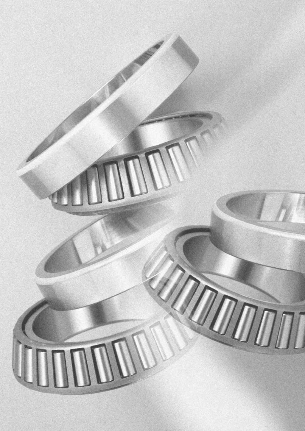
225


 Thee ae both metic and inch seies, and they have been standadized as shown in the following table.")
226 Tapeed Rolle Beaings Single ow tapeed olle beaings Double ow tapeed olle beaings Fou ow tapeed olle beaings 1. Types, design featues, and chaacteistics Tapeed olle beaings ae designed so the tapeed vetex of the aceway sufaces of the inne and oute ings and olles convege at one point on the centeline of the beaing. Due to this design featue, olles move along the cente of the aceway sufaces. The tapeed olles ae guided by the compound foce of the inne and oute aceway sufaces which keep them pessed up against the lage ib on the inne ing. A lage vaiety of these beaings, including single, double, and fou ow aangements, ae in use both in metic and inch seies. Fig. 1 Table 1 Tapeed olle beaing types and chaacteistics Type Chaacteistics (1) Thee ae both metic and inch seies, and they have been standadized as shown in the following table. Dimension seies Metic seies Inch seies Regulations Basic numbe JISB 1512 ISO 355 Example, 321 T2EE4 ABMA (includes metic J-seies) Inne ing no. / oute ing no. ("J" appeas at the beginning of the basic numbe in the case of J-seies.) Dimension seies peviously not coveed by 3XX ae egulated unde JIS B 1512; dimensions peviously missing fom 3XX will hencefoth use the beaing numbe. (2) In addition to level type, thee ae also medium contact angle and lage contact angle types, and the contact angle code C and D, espectively, is appended to the basic numbes of the latte two types. Single ow tapeed olle beaings (3) Subunits Tapeed olle beaings can be disassembled into pats the inne ing, olles, and cage (collectively known as the "cone") and the oute ing (known as the "cup"). These ae the beaing s "subunits". Subunit dimensions ae standadized unde ISO o ABMA standads, and unified subunits ae intechangeable within each dimensional standad. Howeve, high pecision gade beaings ae geneally not intechangeable, and these subunits must be used by assembling only subunits with identical manufactuing numbes. Aside fom any cautionay notes that may appea, the single ow tapeed olle beaings listed in the dimension tables have subunits standadized fo both metic and inch systems (including J seies). (Refe to Fig. 2) Subunit dimensions 2α E EOute ing (cup) nominal small-end diamete αnominal contact angle Fig. 2 Continued on next page B-119
227 Tapeed Rolle Beaings Table 1 (continued) Type Chaacteistics (4) These beaings ae constucted to have a high capacity fo adial loads, axial loads, and combined loads. The lage the contact angle, the geate the axial load capacity becomes. When a pue adial load is placed on the beaings, an induced load in the axial diection is also geneated, and so these beaings ae geneally used in pais aanged face to face. Single ow tapeed olle beaings (5) When used in pais, pope intenal cleaances and peload can be set by adjusting the distance between the two beaings' inne and oute ings. (6) Single ow tapeed olle beaings ae sepaable, so both the inne and oute ings can be used with tight fits. (7) Tapeed olle beaings ae also manufactued with flanges attached to the oute ings. Fo moe details, contact NTN Engineeing. (Refe to Fig. 3) Fig. 3 Double ow tapeed olle beaings (1) Back-to-back aangement (using double ow oute ings) and face-to-face aangement (using double ow inne ings) ae both available, and they have been adjusted so that each type's intenal cleaance values ae fixed. Theefoe, only pats with identical manufactuing numbes can be used and they must be assembled accoding to thei code numbes. (Refe to Fig. 4) (2) The axial intenal cleaances fo double and duplex beaings ae listed in Table 8, 9 on pages A-58. (3) Pais of duplex single ow tapeed olle beaings ae also manufactued. Fo moe details, contact NTN Engineeing. Face-to-face Back-to-back Fig. 4 (1) As shown in Fig. 5, fou ow tapeed olle beaings ae constucted of two double ow inne ings and two double ow oute ings. Fou ow tapeed olle beaings (2) Life of lage beaings is extended by using case hadened steel, hollow olles and pin-type cages. (3) Used pimaily whee heavy load capacity is impotant, and in the olle necks of olling mills. Fig Standad cage type In geneal, pessed cages ae used in tapeed olle beaings. Howeve, fo lage sized beaings, machined o pin type cages ae also used; and fo small sized beaings, molded esin cages ae also used. 3. Allowable misalignment 4. Pecautions when using If beaing load is light duing opeation, o if the atio of axial to adial load fo duplex and double ow beaings exceeds the value of e, slipping develops between the olles and aceway, sometimes esulting in smeaing. The mass of olles and cages paticulaly tends to be lage fo lage tapeed olle beaings. Fo details, please contact NTN Engineeing. Single ow and back-to-back aangement:.5ad(1.5') Face-to-face aangement:.1ad (3.5') In situations whee lage displacement is necessay, please consult NTN Engineeing. B-12

228 Tapeed Rolle Beaings 5. ECO-Top tapeed olle beaings In ecent yeas, thee has been an inceasing demand fo small and medium tapeed olle beaings that contibute to enegy savings, highe output, longe life, highe speed and moe efficient assembly, paticulaly fo automobiles. NTN Engineeing is esponding to this demand by poviding beaings with special specifications based on 4Top tapeed olle beaings, which ae standad beaings. In ode to contibute to the ecology movement, in addition to enhancing existing special specifications, NTN Engineeing has developed the next-geneation NTN Engineeing tapeed olle beaing ECO-Top tapeed olle beaing having impoved long life, low toque, anti-seizue, easy assembly specifications. The featues ae as follows (compaed with NTN Engineeing standad beaings): (1) Ten times longe life using contaminated lubicant (2) Two times longe life using clean lubicant (3) At least 1% lowe toque in pactical otation ange (4) 25% bette anti-seizue pefomance (5) Two times bette loss-of-peload esistance (6) Half educed numbe of evolutions to stable assembled beaing width Fo details, please contact NTN Engineeing. Eco-Top tapeed olle beaings B-121
229 Tapeed Rolle Beaings Inch seies Tapeed Rolle Beaings (single ow) index Seies Cone / cup Page of beaing numbe numbe dimension table /332 B /332 B /332 B A/354A B /354A B /354A B A/354A B S/352 B /362A B /362A B /362A B /362A B A/362 B S/362A B A/362A B A/362A B /382A B A/382A B A/382A B /382A B A/382A B A/382A B S/382A B A/382A B /382A B A/382A B /394A B A/394A B /394A B A/394A B /394A B /394A B A/394A B /414 B /414 B /432 B /432 B /453X B /453X B /453X B /453X B /453A B /453X B /454 B /472 B /472 B /472 B /472 B /472 B /493 B A/493 B AS/493 B /493 B /492A B-177 Seies Cone / cup Page of beaing numbe numbe dimension table /493 B /522 B /522 B /522 B /532X B /532X B /532X B /552A B S/552A B S/552A B /552A B /552A B /552A B S/552A B /563 B /563 B /563 B A/563 B /563 B /572 B S/572 B /572 B /572 B /572 B /572 B /572 B /592A B /592A B A/592XE B /592A B /592A B A/592A B /612 B /612 B /612 B /632 B /632 B /633 B /632 B /632 B /653 B /653 B /653 B /652 B /653 B /653 B /672 B /672 B /672 B /672 B /742 B /742 B A/742 B S/742 B-173 Seies Cone / cup Page of beaing numbe numbe dimension table /742 B A/742 B A/752 B /752 B /752 B /752 B /752 B /772 B /772 B /792 B A/792 B /832 B /832 B /832 B /854 B /892 B /892 B /932 B /932 B /932 B /122 B /1328 B /1329 B /1729 B /1729 B /1729 B /1729 B /193 B /1931 B /1932 B /242 B /2523 B /2523 B /252 B /2523 B /2523 B /2523 B /2631 B /2631 B /2631 B /2631 B /2631 B /272 B /272 B /272 B /272 B /272 B /272 B /2729 B /2735X B /282 B /282 B /2924 B /312 B-151 B-122
230 Tapeed Rolle Beaings Inch seies Tapeed Rolle Beaings (single ow) index Seies Cone / cup Page of beaing numbe numbe dimension table /312 B /312 B /312 B /332 B /3321 B /3339 B /332 B /342 B /342 B /342 B /342 B /3525 B /352 B /3525 B /3525 B /3525 B /3525 B-161 JS35 JS3549A/JS351 B /372 B /372 B /372 B /372 B /372 B /372 B /3726 B /3732 B /372 B /372 B /382 B /382 B /382 B /392 B /392 B /392 B /392 B /3925 B /392 B-171 A4 A45/A4138 B-147 A4 A459/A4138 B /4335 B /4335 B /5335 B /5535 B /5535 B /5535 B /5735 B-173 A6 A675/A6157 B /622 B /632 B /632 B /642 B /642 B A/642 B C/6535 B-175 Seies Cone / cup Page of beaing numbe numbe dimension table /6535 B /6535 B /242 B /242 B /242 B /282 B /282 B /282 B /282 B /3162 B /5185 B /5185 B /5185 B /5185 B /7196 B /7196 B /7196 B /7196 B /7196 B /7196 B /7196 B /724 B S/7196 B /9195 B /9195 B /9196 B /9195 B /9195 B /113 B /11315 B /1152 B-147 LM117 LM11749/LM1171 B-147 LM119 LM11949/LM1191 B /1233 B /1252 B-147 M126 M12648/M1261 B-147 M126 M12649/M1261 B-147 LM127 LM12749/LM12711 B /13621 B /13621 B /1383 B /14274 B /14276 B A/14276 B /14276 B A/14276 B /14276 B A/14276 B /14276 B /15245 B /15243 B /15245 B /15245 B /15245 B-149 Seies Cone / cup Page of beaing numbe numbe dimension table /15245 B /15245 B /15245 B /15245 B /15245 B /15245 B /15245 B /15245 B /15245 B /15523 B /1552 B /15523 B /16284 B /16282 B /17244 B /17244 B /1752 B /1852 B /1862 B /1862 B /1872 B /18724 B /19281 B /21212 B /2272 B /23256 B /2472 B /2552 B /2552 B /2552 B /2552 B /2552 B /2552 B /25519 B /2552 B /25522 B /25526 B /2552 B /2582 B /25821 B /25821 B /26822 B /26822 B /26823 B /26824 B /26822 B /26822 B /26822 B /2762 B /2762 B /2762 B /2762 B /2782 B /283 B-157 B-123
231 Tapeed Rolle Beaings Inch seies Tapeed Rolle Beaings (single ow) index Seies Cone / cup Page of beaing numbe numbe dimension table /28315 B /283 B /28521 B /28521 B /28521 B /28622 B /28622 B /28622 B /28921 B /2892 B /2892 B /2952 B /29521 B /2952 B /2952 B /2962 B /2963 B /2962 B /2962 B-173 LM297 LM29748/LM2971 B /3152 B /3152 B /3152 B /33462 B /33462 B /33462 B /33462 B /33821 B /33821 B /33821 B /33822 B /34478 B /34478 B /34478 B /34478 B /3662 B /3692 B /37625 B /37625 B /3952 B /3952 B /3952 B /3952 B /3952 B /41286 B /42584 B /42584 B /42584 B /42584 B /42584 B /4262 B /4262 B /43312 B /44348 B-155 Seies Cone / cup Page of beaing numbe numbe dimension table /44348 B /44348 B-157 L446 L4464/L4461 B-149 L446 L44643/L4461 B-149 L446 L44649/L4461 B /4522 B /4522 B /4522 B /4522 B /4522 B-167 L454 L45449/L4541 B /46368 B /46368 B /4672 B /4672 B /4742 B /4742 B /4762 B /4762 B /4762 B /4782 B /4782 B /4822 B /4822 B /4832 B /4832 B-183 LM485 LM48548/LM4851 B-153 LM485 LM48548A/LM4851 B /4862 B /4862 B /4952 B /52618 B /52618 B /52618 B /52618 B /53375 B /53375 B C 55175C/55437 B C 55176C/55437 B C 55187C/55437 B C 552C/55443 B /5665 B /59412 B /647 B /647 B /655 B /6532 B /66462 B /66462 B /6652 B /6652 B-167 LM67 LM6748/LM671 B /67322 B /67322 B-181 Seies Cone / cup Page of beaing numbe numbe dimension table /67322 B /67322 B /6772 B /68712 B /68712 B-181 L681 L68149/L68111 B-155 L693 JL69349/JL6931 B /7175 B /72487 B C 722C/72487 B C 72212C/72487 B C 72218C/72487 B C 72225C/72487 B-167 LM728 LM72849/LM7281 B /7485 B /7485 B /7485 B /78551 B /78551 B C 78214C/78551 B-165 LM783 LM78349/LM7831C B-155 LM783 LM78349A/LM7831A B-155 M845 M84548/M8451 B-149 M866 M86643/M8661 B-149 M866 M86647/M8661 B-151 M866 M86649/M8661 B-151 M88 M8848/M881 B-153 HM885 JHM8854/JHM88513 B-151 HM885 HM88542/HM8851 B-153 HM885 HM88542/HM88512 B-153 HM885 HM88547/HM8851 B-153 HM886 HM88648/HM8861 B-155 HM886 HM88648/HM88611AS B-155 HM886 HM88649/HM8861 B-153 HM894 HM8944/HM8941 B-153 HM894 HM89443/HM8941 B-153 HM894 HM89444/HM8941 B-153 HM894 HM89446/HM8941 B-155 HM894 HM89448/HM8941 B-155 HM894 HM89449/HM8941 B-155 HM894 HM89449/HM89411 B J9354/J9748 B /9744 B /95925 B /9595 B /95925 B /979 B /991 B /991 B-183 LM129 LM12949/LM1291 B-161 LM149 JLM14948/JLM1491 B-163 LM149 LM14947A/LM14911 B-163 LM149 LM14949/LM14911 B-163 M251 JM25149/JM2511 B-163 B-124
232 Tapeed Rolle Beaings Inch seies Tapeed Rolle Beaings (single ow) index Seies Cone / cup Page of beaing numbe numbe dimension table M27 JM2749/JM271 B-167 H2117 JH211749/JH21171 B-171 HM212 HM21244/HM21211 B-169 HM212 HM21246/HM21211 B-169 HM212 HM21249/HM2121 B-171 L2178 L217849/L21781 B-177 LL2178 LL217849/LL21781 B-177 HM2182 HM218248/HM21821 B-177 HH2214 HH22143/HH22141 B-175 HH2214 HH221431/HH22141 B-175 HH2214 HH22144/HH22141 B-179 HH2214 HH221449/HH22141 B-179 HH2214 HH221449A/HH22141 B-179 HH2243 HH224334/HH22431 B-179 HH2243 HH224335/HH22431 B-179 HH2243 HH224346/HH22431 B-181 HH2283 HH228349/HH22831 B-181 M2316 M231648/M23161 B-183 LM38 LM3849/LM3811 B-157 H377 JH37749/JH3771 B-167 HM3184 JHM318448/JHM31841 B-177 L3192 L319249/L31921 B-179 L3272 L327249/L32721 B-181 H4142 H414242/H41421 B-171 H4142 H414245/H41421 B-171 H4142 H414249/H41421 B-173 H4156 JH415647/JH41561 B-173 L4323 L432349/L43231 B-183 LM513 LM51349/LM5131 B-157 LM513 LM51349/LM51314 B-157 LM533 LM53349A/LM5331 B-161 HH563 HH56348/HH5631 B-163 HH563 HH56349/HH5631 B-163 LM568 JLM56849/JLM5681 B-165 LM587 JLM58748/JLM5871 B-167 M5119 JM511946/JM51191 B-169 M5156 JM515649/JM51561 B-175 HM5164 HM516442/HM51641 B-173 HM5164 HM516448/HM51641 B-175 HM5168 JHM516849/JHM51681 B-177 LM5225 LM522546/LM52251 B-179 LM5225 LM522548/LM52251 B-181 HM5226 JHM522649/JHM52261 B-181 HM5341 JHM534149/JHM53411 B-183 LM63 LM6349/LM6311 B-164 L615 L61549/L6151 B-169 M6129 JM612949/JM61291 B-171 HM617 HM61749/HM6171 B-177 L633 L63349/L6331 B-183 LL6392 LL639249/L63921 B-183 LM746 JLM74649/JLM7461 B-163 LM719 JLM71949/JLM7191 B-169 LM7141 JLM714149/JLM71411 B-173 M7142 JM714249/JM71421 B-173 Seies Cone / cup Page of beaing numbe numbe dimension table H7153 H715334/H B-169 H7153 H715343/H B-171 H7153 H715345/H B-173 H7153 H715348/H B-175 M7166 JM716648/JM71661 B-177 M7181 JM718149/JM71811 B-177 M7191 JM719149/JM B-177 M722 JM72249/JM7221 B-179 L7243 JL724348/JL B-181 M7361 JM736149/JM73611 B-183 M7382 JM738249/JM73821 B-183 HM813 HM81346/HM8131 B-157 HM813 HM81349/HM8131 B-157 M82 M8248/M8211 B-159 HM831 HM83145/HM8311 B-159 HM831 HM83149/HM8311 B-159 M84 M8448/M841 B-161 M848 M84846/M8481 B-161 M848 M84848/M8481 B-163 M848 M84849/M8481 B-163 HM848 HM8484/HM8481 B-159 HM848 HM84842/HM8481 B-159 LM866 LM86649/LM8661 B-165 HM87 HM874/HM871 B-161 HM87 HM8744/HM871 B-163 HM87 HM8746/HM871 B-163 HM87 HM8748/HM871 B-165 HM87 HM8749/HM871 B-165 HM87 JHM8745/JHM8712 B-163 L8121 L812148/L B-171 LM813 JLM81349/JLM8131 B-171 HM8138 HM81384/HM81381 B-167 HM8138 HM813841/HM81381 B-169 HM8138 HM813842/HM81381 B-169 HM8138 HM813844/HM81381 B-171 L8147 L814749/L81471 B-173 LM8148 LM814849/LM81481 B-175 M822 JM82249/JM8221 B-181 HM932 HM93245/HM9321 B-159 HM932 HM93249/HM9321 B-159 M933 M93345/M9331 B-159 HM976 HM97643/HM97614 B-165 HM9112 HM911242/HM91121 B-165 HM9112 HM911245/HM91121 B-169 HM9112 HM911244/JHM B-169 H9138 H91384/H91381 B-167 H9138 H913842/H91381 B-169 H9138 JH913848/JH B-173 H9178 H91784/H91781 B-175 H924 H92445/H9241 B-181 HM9267 HM92674/HM92671 B-181 HM9267 HM926747/HM92671 B-181 B-125
233 Tapeed Rolle Beaings Inch seies Tapeed Rolle Beaings (fou ow) index Seies Cone / cup Page of beaing numbe numbe dimension table 85 T-8576D/852/852D B D/4672/46721D B T-4829D/4822/4822D B T-48393D/4832/4832D B T-4868D/4862/4862D B D/6772/67721D B T-67885D/6782/6782D B D/81962/81963D B D/8262/8262D B EE12696D/12615/126151D B EE12797D/127137/127137D B EE13282D/132125/132126D B EE13412D/134143/134144D B-27 L1631 L163149D/L16311/L16311D B EE171D/17145/17145D B EE22127D/221575/221576D B-27 M2247 M224749D/M22471/M22471D B-23 M2316 T-M231649D/M23161/M23161D B-23 M2388 M238849D/M23881/M23881D B-23 M2415 M241538D/M24151/M24151D B-25 M2442 T-M244249D/M24421/M24421D B-25 LM2477 LM247748D/LM24771/LM24771DA B-25 M2497 T-M249748D/M24971/M24971D B-25 HM2523 HM252349D/HM25231/HM25231D B-27 M2523 T-M252349D/M25231/M25231D B-27 M2554 M255449D/M25541/M25541DA B-27 HM2568 T-HM256849D/HM25681/HM25681DG2 B-27 M2571 M257149D/M25711/M25711D B-27 M2572 M257248D/M25721/M25721D B-29 LM2586 LM258649D/LM25861/LM25861D B-29 HM259 T-HM25949D/HM2591/HM2591D B-29 HM261 HM26149D/HM2611/HM2611DA B-29 M2624 M262449D/M26241/M26241D B-29 HM2627 T-HM262749D/HM26271/HM26271DG2 B-29 LM2631 LM263149D/LM26311/LM26311D B-29 Seies Cone / cup Page of beaing numbe numbe dimension table M2633 M263349D/M26331/M26331D B-29 HM265 HM26549D/HM2651/HM2651D B-211 HM2664 T-HM266449D/HM26641/HM26641DG2 B-211 M2687 T-M268749D/M26871/M26871DG2 B-211 M277 M27749D/M2771/M2771DAG2 B-211 LM2722 LM272249D/LM27221/LM27221DG2 B-213 M2741 M274149D/M27411/M27411DG2 B-213 LM2744 LM274449D/LM27441/LM27441D B EE27516D/275155/275156D B EE27519D/27516/275161D B-27 M2753 M275349D/M27531/M27531DG2 B-213 M2764 M276449D/M27641/M27641DG2 B-213 M2787 M278749D/M27871/M27871DAG2 B-213 LM2788 LM278849D/LM27871/LM27871D B EE287D/2812/28121D B-23 M28 M2849D/M281/M281DG2 B-215 L2811 L281149D/L28111/L28111DG2 B-215 M2816 M281649D/M28161/M28161DG2 B-215 LM2818 LM281849D/LM28181/LM28181DG2 B-215 M2822 M282249D/M28221/M28221DG2 B-215 M2834 M283449D/M28341/M28341DG2 B-215 LM2836 LM283649D/LM28361/LM28361DG2 B-215 M2842 M284249D/M28421/M28421DG2 B-215 M2858 M285848D/M28581/M28851DG2 B-215 LM2862 LM286249D/LM28621/LM28621DG2 B-217 LM2876 LM287649D/LM28761/LM28761DG2 B-217 LM2889 LM288949D/LM28891/LM28891DG2 B EE29122D/29175/291751D B EE329119D/329172/329173D B-27 LM3774 LM377449D/LM37741/LM37741DG2 B-213 LM4513 T-LM451349D/LM45131/LM45131D B EE526131D/52619/52619D B EE547341D/54748/547481DG2 B T-EE64193D/6426/64261DG2 B EE649241D/64931/649311DG2 B-215 B-126
234 Tapeed Rolle Beaings Inch seies Tapeed Rolle Beaings (fou ow) index Seies Cone / cup Page of beaing numbe numbe dimension table LM6546 T-LM654644D/LM65461/LM65461D B-27 LM6546 T-LM654648D/LM65461/LM65461D B EE655271D/655345/655346DG2 B-215 LM6659 LM665949D/LM66591/LM66591D B-211 M6679 M667947D/M667911/M667911DG2 B EE79D/7167/7168D B-25 LM7427 T-LM742749D/LM742714/LM742714D B EE755281D/75536/755361DG2 B-215 M7574 M757448D/M75741/M75741D B-27 M7574 M757449D/M75741/M75741D B-29 LM7616 LM761648D/LM76161/LM76161D B-29 LM7616 LM761649D/LM76161/LM76161D B-29 LM7634 LM763449D/LM76341/LM76341D B-29 LM7651 LM765149D/LM76511/LM76511D B-211 LM7677 LM767745D/LM76771/LM76771D B-211 LM7677 LM767749D/LM76771/LM76771D B-211 LM7693 LM769349D/LM76931/LM76931D B-211 L778 L77849D/L7781/L7781DG2 B-213 LM7727 LM772749D/LM77271/LM77271DA B-213 LM7785 LM778549D/LM77851/LM77851DG2 B EE82211D/822175/822176D B EE833161D/833232/833233D B EE843221D/84329/843291D B-213 LM8694 T-LM869449D/LM86941/LM86941DG2 B EE91163D/9124/91241D B EE92115D/921875/921876D B EE971355D/9721/97213D B-29 B-127
235 Tapeed Rolle Beaings Metic seies 1 T C D B d a d 15 3mm Bounday dimensions Basic load atings Limiting speeds Beaing d D T B C s min 1) dynamic static dynamic static numbes mm kn kgf min -1 ls min 1) C C o C C o gease oil T T T T-3223R 2) T T-324X T T T-334A T-334CA T T-32/22X T-325X T T T T-3225R 2) T-3225C T-3225CR 2) T T T-335C T-335D T T-32/28X T-332/ T-326X T T T T-3226C T T-336 1)Minimal allowable dimension fo chamfe dimension o 1. 2)This beaing does not incopoate the subunit dimensions. B-128
236 Tapeed Rolle Beaings Sa Sb 1a Equivalent adial load dynamic P=XF+YFa Da db a da Db Fa F e Fa F >e X Y X Y 1.4 Y2 static Po=.5F+YoFa When Po<F use Po=F Fo values of e, Y2 and Yo see the table below. Dimensions Abutment and fillet dimensions Load Constant Axial Mass seies to cente load factos ISO mm mm kg d a d b D a D b S a S b as 1as min max max min min min min max max a e Y 2 Y o (appox.) 2FB DB DD FB CC DB DD FB FD CC CC CE CC CD CD DE FB FB FD CC DE CC CE DB DC DC DE FB B-129
237 Tapeed Rolle Beaings Metic seies 1 T C D B d a d 3 45mm Bounday dimensions Basic load atings Limiting speeds Beaing d D T B C s min 1) dynamic static dynamic static numbes mm kn kgf min -1 ls min 1) C C o C C o gease oil T-336CA T-336D T * 4T-3236C T-3236CR 2) T-32/32X T-332/ T-323/32C XU T-327X T T T T-3227C T-3227CR 2) T T T-337C T-337D T T-3237C XU T-328X T T T T T T-T2EE T T-338C T-338D U T-3238C * 3299XU 1)Minimal allowable dimension fo chamfe dimension o 1. 2)This beaing does not incopoate the subunit dimensions. Note: When selecting beaings with beaing numbes maked with " * ", please consult NTN Engineeing. B-13
238 Tapeed Rolle Beaings Sa Sb 1a Equivalent adial load dynamic P=XF+YFa Da db a da Db Fa F e Fa F >e X Y X Y 1.4 Y2 static Po=.5F+YoFa When Po<F use Po=F Fo values of e, Y2 and Yo see the table below. Dimensions Abutment and fillet dimensions Load Constant Axial Mass seies to cente load factos ISO mm mm kg d a d b D a D b S a S b as 1as min max max min min min min max max a e Y 2 Y o (appox.) FB FD FD CC DE FD BD CC CE DB DC DC DE FB FB FE FE BC CD BE CE DB DC DE EE FB FB FD FD BC B-131
239 Tapeed Rolle Beaings Metic seies 1 T C D B d a d 45 6mm Bounday dimensions Basic load atings Limiting speeds Beaing d D T B C s min 1) dynamic static dynamic static numbes mm kn kgf min -1 ls min 1) C C o C C o gease oil T-329X T T T T T T T-339D U * 3291XU ) T-321X T T T T T T-T2ED T-T7FC T T-331D U XU T-3211X T T T T T T T-3311D U XA 2) T-3212X T T )Minimal allowable dimension fo chamfe dimension o 1. 2)This beaing does not incopoate the subunit dimensions. B-132
240 Tapeed Rolle Beaings Sa Sb 1a Equivalent adial load dynamic P=XF+YFa Da db a da Db Fa F e Fa F >e X Y X Y 1.4 Y2 static Po=.5F+YoFa When Po<F use Po=F Fo values of e, Y2 and Yo see the table below. Dimensions Abutment and fillet dimensions Load Constant Axial Mass seies to cente load factos ISO mm mm kg d a d b D a D b S a S b as 1as min max max min min min min max max a e Y 2 Y o (appox.) 3CC CE CE DB DC DE FB FB FD BC CC CE CE DB DC DE ED FC FB FB FD BC CC CE CE DB DC DE FB FB FD CC CE CE Note: When selecting beaings with beaing numbes maked with " * ", please consult NTN Engineeing. B-133
241 Tapeed Rolle Beaings Metic seies 1 T C D B d a d 6 75mm Bounday dimensions Basic load atings Limiting speeds Beaing d D T B C s min 1) dynamic static dynamic static numbes mm kn kgf min -1 ls min 1) C C o C C o gease oil T U U T-T2EE T-T7FC U T-3312D U XU T-3213X T T T U U U T-3313D U XU T-3214X T T U U T-T7FC U T-3314D U XU XU U T U U U DU 1)Minimal allowable dimension fo chamfe dimension o 1. B-134
242 Tapeed Rolle Beaings Sa Sb 1a Equivalent adial load dynamic P=XF+YFa Da db a da Db Fa F e Fa F >e X Y X Y 1.4 Y2 static Po=.5F+YoFa When Po<F use Po=F Fo values of e, Y2 and Yo see the table below. Dimensions Abutment and fillet dimensions Load Constant Axial Mass seies to cente load factos ISO mm mm kg d a d b D a D b S a S b as 1as min max max min min min min max max a e Y 2 Y o (appox.) 3EB EC EE EE FC FB FB FD BC CC CE DE EB EC EE GB GB GD BC CC CE EB EC EE FC GB GB GD BC CC CE DB DC EE GB GB B-135
243 Tapeed Rolle Beaings Metic seies 1 T C D B d a d 75 95mm Bounday dimensions Basic load atings Limiting speeds Beaing d D T B C s min 1) dynamic static dynamic static numbes mm kn kgf min -1 ls min 1) C C o C C o gease oil U XU XU U U U U U DU U XU XU U U U U U DU U XU XU U U U U DU U XU XU U U U U ) DU 1)Minimal allowable dimension fo chamfe dimension o 1. 2)This beaing does not incopoate the subunit dimensions. B-136
244 Tapeed Rolle Beaings Sa Sb 1a Equivalent adial load dynamic P=XF+YFa Da db a da Db Fa F e Fa F >e X Y X Y 1.4 Y2 static Po=.5F+YoFa When Po<F use Po=F Fo values of e, Y2 and Yo see the table below. Dimensions Abutment and fillet dimensions Load Constant Axial Mass seies to cente load factos ISO mm mm kg d a d b D a D b S a S b as 1as min max max min min min min max max a e Y 2 Y o (appox.) 2GD BC CC CE EB EC EE GB GB GD BC CC CE EB EC EE GB GB GD BC CC CE FB FC GB GB GD BC CC CE FB FC GB GB Note: When selecting beaings with beaing numbes maked with " * ", please consult NTN Engineeing. B-137
245 Tapeed Rolle Beaings Metic seies 1 T C D B d a d 95 12mm Bounday dimensions Basic load atings Limiting speeds Beaing d D T B C s min 1) dynamic static dynamic static numbes mm kn kgf min -1 ls min 1) C C o C C o gease oil U * 3292XU ) T-T4CB XU U U U U ) XU U XA 2) XU U U U * 3321U ) * 31321XU U XA 2) XU U U U * 3322U ) XU * 32322U ) * 32924XU ) XU U 1)Minimal allowable dimension fo chamfe dimension o 1. 2)This beaing does not incopoate the subunit dimensions. B-138
246 Tapeed Rolle Beaings Sa Sb 1a Equivalent adial load dynamic P=XF+YFa Da db a da Db Fa F e Fa F >e X Y X Y 1.4 Y2 static Po=.5F+YoFa When Po<F use Po=F Fo values of e, Y2 and Yo see the table below. Dimensions Abutment and fillet dimensions Load Constant Axial Mass seies to cente load factos ISO mm mm kg d a d b D a D b S a S b as 1as min max max min min min min max max a e Y 2 Y o (appox.) 2GD CC CB CC CE FB FC GB GB GD DC DE FB FC GB GB GD DC DE FB FC GB GB GD CC DC FB Note: When selecting beaings with beaing numbes maked with " * ", please consult NTN Engineeing. B-139
247 Tapeed Rolle Beaings Metic seies 1 T C D B d a d 12 17mm Bounday dimensions Basic load atings Limiting speeds Beaing d D T B C s min 1) dynamic static dynamic static numbes mm kn kgf min -1 ls min 1) C C o C C o gease oil U U ) XU U * 32926XU ) XU U U U XU XU XU * 3228U ) U U XU XU XU U U * 333U ) XU XU XU U U * 3332U ) XU 1)Minimal allowable dimension fo chamfe dimension o 1. 2)This beaing does not incopoate the subunit dimensions. B-14
248 Tapeed Rolle Beaings Sa Sb 1a Equivalent adial load dynamic P=XF+YFa Da db a da Db Fa F e Fa F >e X Y X Y 1.4 Y2 static Po=.5F+YoFa When Po<F use Po=F Fo values of e, Y2 and Yo see the table below. Dimensions Abutment and fillet dimensions Load Constant Axial Mass seies to cente load factos ISO mm mm kg d a d b D a D b S a S b as 1as min max max min min min min max max a e Y 2 Y o (appox.) 4FD GB GB GD CC EC FB FD GB GB CC DC FB FD GB GB DC EC GB GD GB GB DC EC GB GD GB DC Note: When selecting beaings with beaing numbes maked with " * ", please consult NTN Engineeing. B-141
249 Tapeed Rolle Beaings Metic seies 1 T C D B d a d 17 3mm Bounday dimensions Basic load atings Limiting speeds Beaing dynamic static dynamic static numbes mm kn kgf min -1 1) 1) d D T B C s min ls min C C o C C o gease oil XU U U * 3334U ) XU XUE U U * 32938XU ) XUE U * 32238U ) XUE XUE U U * 32944XUE E1 2) XU XUE XU XUE XU XUE XU XUE XU 1)Minimal allowable dimension fo chamfe dimension o 1. 2)This beaing does not incopoate the subunit dimensions. B-142
250 Tapeed Rolle Beaings Sa Sb 1a Equivalent adial load dynamic P=XF+YFa Da db a da Db Fa F e Fa F >e X Y X Y 1.4 Y2 static Po=.5F+YoFa When Po<F use Po=F Fo values of e, Y2 and Yo see the table below. Dimensions Abutment and fillet dimensions Load Constant Axial Mass seies to cente load factos ISO mm mm kg d a d b D a D b S a S b as 1as min max max min min min min max max a e Y 2 Y o (appox.) 4EC GB GD GB DC FD GB GD DC FD GB GD EC FD GB GD EC FD EC FD EC FC EC FC FD GD Note: When selecting beaings with beaing numbes maked with " * ", please consult NTN Engineeing. B-143
251 Tapeed Rolle Beaings Metic seies 1 T C D B d a d 32 36mm Bounday dimensions Basic load atings Limiting speeds Beaing dynamic static dynamic static numbes mm kn kgf min -1 1) 1) d D T B C s min ls min C C o C C o gease oil * 32964XUE E1 2) XU * 32968XUE E1 2) XUE1 1)Minimal allowable dimension fo chamfe dimension o 1. 2)This beaing does not incopoate the subunit dimensions. B-144
252 Tapeed Rolle Beaings Sa Sb 1a Equivalent adial load dynamic Da db a da Db P=XF+YFa Fa F e Fa F >e X Y X Y 1.4 Y2 static Po=.5F+YoFa When Po<F use Po=F Fo values of e, Y2 and Yo see the table below. Dimensions Abutment and fillet dimensions Load Constant Axial Mass seies to cente load factos ISO mm mm kg d a d b D a D b S a S b as 1as min max max min min min min max max a e Y 2 Y o (appox.) 3FD GD FD FD Note: When selecting beaings with beaing numbes maked with " * ", please consult NTN Engineeing. B-145
253 Tapeed Rolle Beaings Inch seies 1 T C D B d a d mm Bounday dimensions Basic load atings Limiting speeds dynamic static dynamic static mm kn kgf min -1 d D T B C C C o C C o gease oil Note: 1. Chamfe dimensions on the back face of the inne and oute ings of the beaing ae lage than maximum values fo installation dimensions as and 1as. 2. As fo the maximum value fo inne and oute ing diametes of beaings whose beaing numbes ae maked with " " (inne ing) and " " (oute ing), the pecision class is an intege fo class 4 and class 2 beaings only. B-146
254 Tapeed Rolle Beaings Da db 1a a da Db Equivalent adial load dynamic P=XF+YFa Fa F e Fa F >e X Y X Y 1.4 Y2 static Po=.5F+YoFa When Po<F use Po=F Fo values of e, Y2 and Yo see the table below. Beaing numbes Abutment and fillet dimensions Load Constant Axial Mass cente load factos mm mm kg as 1as d a d b D a D b max max a e Y 2 Y o (appox.) 4T-A45/A T-A459 /A T-362/ T-1159/ T-1758/ T-562/ T-962/ T-566/ T-LM11749/LM T-A675/A T-LM11949/LM T-575/ T-967/ T-978/ T-967/ T-2175/ T-1775/ T-579 / T-779/ T-981/ T-1258/ T-M12649/M T-LM12749 /LM T-787/ T-M12648/M T-138/ T-138/ B-147
255 Tapeed Rolle Beaings Inch seies 1 T C D B d a d mm Bounday dimensions Basic load atings Limiting speeds dynamic static dynamic static mm kn kgf min -1 d D T B C C C o C C o gease oil Note: 1. Chamfe dimensions on the back face of the inne and oute ings of the beaing ae lage than maximum values fo installation dimensions as and 1as. 2. As fo the maximum value fo inne ing boe diametes of beaings whose beaing numbes ae maked with " " (inne ing), the pecision class is an intege fo class 4 and class 2 beaings only. B-148
256 Tapeed Rolle Beaings Da db 1a a da Db Equivalent adial load dynamic P=XF+YFa Fa F e Fa F >e X Y X Y 1.4 Y2 static Po=.5F+YoFa When Po<F use Po=F Fo values of e, Y2 and Yo see the table below. Beaing numbes Abutment and fillet dimensions Load Constant Axial Mass cente load factos mm mm kg as 1as d a d b D a D b max max a e Y 2 Y o (appox.) 4T-1755/ T-128/ T-LM72849/LM T-793/ T-L4464/L T-1779/ T-798/ T-797/ T-796/ T-71/ T-71S/ T-L44643/L T-71/ T-178/ T-M84548/M T-1511/ T-151/ T-1512/ T-M86643/M T-231/ T-2687/ T-1513/ T-2682/ T-L44649 /L T-1558 / T-1516 / T-2688 / T-1985/ T-1559/ B-149
257 Tapeed Rolle Beaings Inch seies J seies 1 T C D B d a d mm Bounday dimensions Basic load atings Limiting speeds dynamic static dynamic static mm kn kgf min -1 d D T B C C C o C C o gease oil Note: 1. Chamfe dimensions on the back face of the inne and oute ings of the beaing ae lage than maximum values fo installation dimensions as and 1as. 2. As fo the maximum value fo inne ing boe diametes of beaings whose beaing numbes ae maked with " " (inne ing), the pecision class is an intege fo class 4 and class 2 beaings only. B-15
258 Tapeed Rolle Beaings 1a a Equivalent adial load dynamic P=XF+YFa Da db da Db * as 2.3 as min 4.75 min 3.56 Fa Fa F >e e F X Y X Y 1.4 Y2 static Po=.5F+YoFa When Po<F use Po=F Fo values of e, Y2 and Yo see the table below. Beaing numbes Abutment and fillet dimensions Load Constant Axial Mass cente load factos mm mm kg as 1as d a d b D a D b max max a e Y 2 Y o (appox.) 4T-1985/ T-1559/ T-1985/ T-15112/ T-M86647/M T-2689/ T-2474/ T-2474/ T-2578/ T-41125/ T-2872/ T-L45449/L T-269/ T / T / T-14117A/ # 4T-JHM8854/JHM T-15116/ T-17119/ T-M86649/M T-2558/ T-3187/ T-15118/ T-15119/ T-1512/ T-14116/ T-14116/ T-LM6748/LM * T-15123/ * T-15125/ Note: 3. Beaing numbes maked " # " designate J-seies beaings. The toleances of these beaings is listed in Table 6.6 on page A Chamfe dimensions of beaings maked " * " ae shown in dawings. B-151
259 Tapeed Rolle Beaings Inch seies J seies 1 T C D B d a d mm Bounday dimensions Basic load atings Limiting speeds dynamic static dynamic static mm kn kgf min -1 d D T B C C C o C C o gease oil Note: 1. Chamfe dimensions on the back face of the inne and oute ings of the beaing ae lage than maximum values fo installation dimensions as and 1as. 2. Chamfe dimensions of beaings maked " * " ae shown in dawings. B-152
260 Tapeed Rolle Beaings 1a a Equivalent adial load dynamic P=XF+YFa Da db da Db * as 2.3 as min 4.75 min 3.56 Fa Fa F >e e F X Y X Y 1.4 Y2 static Po=.5F+YoFa When Po<F use Po=F Fo values of e, Y2 and Yo see the table below. Beaing numbes Abutment and fillet dimensions Load Constant Axial Mass cente load factos mm mm kg as 1as d a d b D a D b max max a e Y 2 Y o (appox.) 4T-15126/ T-258/ T-2475/ T-2476/ T-14124/ T-14125A/ T-258/ T-2582/ T-3188/ T-3193/ T-2875/ T-2879/ T-HM88542/HM T-HM88542/HM T-HM8944/HM T-3476/ T-M8848/M T-1413/ T-2585/ T-3196/ T-HM88547/HM T-2785/ T-HM89443/HM T-HM89444/HM T-43131/ T-LM48548/LM * T-LM48548A/LM T-14137A/ T-HM88649/HM T-16137/ T-2877/ T-2878/ T-2878/ T-25877/ T-25877/ T-2793/2735X T-2793/ B-153
261 Tapeed Rolle Beaings Inch seies J seies 1 T C D B d a d mm Bounday dimensions Basic load atings Limiting speeds dynamic static dynamic static mm kn kgf min -1 d D T B C C C o C C o gease oil Note: 1. Chamfe dimensions on the back face of the inne and oute ings of the beaing ae lage than maximum values fo installation dimensions as and 1as. 2. As fo the maximum value fo inne and oute ing diametes of beaings whose beaing numbes ae maked with " " (inne ing) and " " (oute ing), the pecision class is an intege fo class 4 and class 2 beaings only. B-154
262 Tapeed Rolle Beaings 1a a Equivalent adial load dynamic P=XF+YFa Da db da Db * as 2.3 as min 4.75 min 3.56 Fa Fa F >e e F X Y X Y 1.4 Y2 static Po=.5F+YoFa When Po<F use Po=F Fo values of e, Y2 and Yo see the table below. Beaing numbes Abutment and fillet dimensions Load Constant Axial Mass cente load factos mm mm kg as 1as d a d b D a D b max max a e Y 2 Y o (appox.) 4T-2793/ T-HM89446/HM T-31593/ T-31594/ T-3478/ T-3379/ T-3872/ T-14139/ T-L68149 /L * T-LM78349A /LM7831A T-LM78349 /LM7831C * # 4T-JS3549A/JS T-26883/ T-339/ T-HM88648/HM T-HM88648/HM88611AS T-2588/ T-278/ T-HM89448/HM T-HM89449/HM T-31597/ T-HM89249/HM T-3479/ T-44143/ ) # 4T-JL69349/JL * T-13889/ T-LM29748/LM * T-13685/ T-13687/ T-1915/ T-1615/ Note: 3. Beaing numbes maked " # " designate J-seies beaings. The toleances of these beaings is listed in Table 6.6 on page A Chamfe dimensions of beaings maked " * " ae shown in dawings. B-155
263 Tapeed Rolle Beaings Inch seies 1 T C D B d a d mm Bounday dimensions Basic load atings Limiting speeds dynamic static dynamic static mm kn kgf min -1 d D T B C C C o C C o gease oil Note: 1. Chamfe dimensions on the back face of the inne and oute ings of the beaing ae lage than maximum values fo installation dimensions as and 1as. 2. As fo the maximum value fo inne and oute ing diametes of beaings whose beaing numbes ae maked with " " (inne ing) and " " (oute ing), the pecision class is an intege fo class 4 and class 2 beaings only. B-156
264 Tapeed Rolle Beaings 1a a Equivalent adial load dynamic P=XF+YFa Da db da Db * as 2.3 as min 4.75 min 3.56 Fa Fa F >e e F X Y X Y 1.4 Y2 static Po=.5F+YoFa When Po<F use Po=F Fo values of e, Y2 and Yo see the table below. Beaing numbes Abutment and fillet dimensions Load Constant Axial Mass cente load factos mm mm kg as 1as d a d b D a D b max max a e Y 2 Y o (appox.) 4T-2815/ T-2776/ T-2788/ T-26878/ T-349/ T-2815/ T-2788/ T-HM81346/HM T-25572/ T-3875/ T-358/ T-4415/ ) T-418/ T-2789/ T-3382/ T-2688/ T-3382/ T-3386/ T-44158/ ) T-28158/ T-344/ T-35A/354A T-42/ T-543/532X T-HM81349/HM T-LM3849 /LM * T-1859/ T-LM51349/LM T-LM51349/LM T-11162/ T-2478/ T-26882/ T-26885/ T-11162/ Note: 3. Chamfe dimensions of beaings maked " * " ae shown in dawings. 1)" " means that load cente at outside on end of inne ing. B-157
265 Tapeed Rolle Beaings Inch seies 1 T C D B d a d mm Bounday dimensions Basic load atings Limiting speeds dynamic static dynamic static mm kn kgf min -1 d D T B C C C o C C o gease oil Note: 1. Chamfe dimensions on the back face of the inne and oute ings of the beaing ae lage than maximum values fo installation dimensions as and 1as. B-158
266 Tapeed Rolle Beaings 1a a Equivalent adial load dynamic P=XF+YFa Da db da Db * as 2.3 as min 4.75 min 3.56 Fa Fa F >e e F X Y X Y 1.4 Y2 static Po=.5F+YoFa When Po<F use Po=F Fo values of e, Y2 and Yo see the table below. Beaing numbes Abutment and fillet dimensions Load Constant Axial Mass cente load factos mm mm kg as 1as d a d b D a D b max max a e Y 2 Y o (appox.) 4T-336/ T-26882/ T-M8248/M T-388/ T-3576/ T-HM83145/HM T-4388/ T-M93345/M ) T-46162/ T-HM8484/HM T-53162/ T-HM93245/HM ) T-4395/ T-2278/ T-25578/ T-3579/ T-26884/ T-25577/ T-12175/ ) T-18685/ T-2558/ T-25582/ T-3578/ T-355/354A T-3578/ T-HM83149/HM T-3782/ T-46175/ T-33885/ T-438/ T-HM84842/HM T-53177/ T-HM93249/HM ) T-527/ T-46/453X )" " means that load cente at outside on end of inne ing. B-159
267 Tapeed Rolle Beaings Inch seies 1 T C D B d a d mm Bounday dimensions Basic load atings Limiting speeds dynamic static dynamic static mm kn kgf min -1 d D T B C C C o C C o gease oil Note: 1. Chamfe dimensions on the back face of the inne and oute ings of the beaing ae lage than maximum values fo installation dimensions as and 1as. 2. As fo the maximum value fo inne and oute ing diametes of beaings whose beaing numbes ae maked with " " (inne ing) and " " (oute ing), the pecision class is an intege fo class 4 and class 2 beaings only. B-16
268 Tapeed Rolle Beaings 1a a Equivalent adial load dynamic P=XF+YFa Da db da Db * as 2.3 as min 4.75 min 3.56 Fa Fa F >e e F X Y X Y 1.4 Y2 static Po=.5F+YoFa When Po<F use Po=F Fo values of e, Y2 and Yo see the table below. Beaing numbes Abutment and fillet dimensions Load Constant Axial Mass cente load factos mm mm kg as 1as d a d b D a D b max max a e Y 2 Y o (appox.) 4T-4528/ T-HM874/HM T-55175C/ ) T-55176C/ ) T-6277/ T-25584/ T-3776/ T-358/354A T-367/362A T-3586/ T-LM12949/LM T-LM6349/LM T-2559/ T-2559/ T-2559/ T-2559/ T-LM53349A /LM * T-1869/ T-25592/ T-359A/354A T-2984/ T-359S/ T-3777/ T-436/ T-369A/362A T-M8448/M T-3778/ T-HM84846/HM T-386A/382A T-528/ T-463/453X Note: 3. Chamfe dimensions of beaings maked " * " ae shown in dawings. 1)" " means that load cente at outside on end of inne ing. B-161
269 Tapeed Rolle Beaings Inch seies J seies 1 T C D B d a d mm Bounday dimensions Basic load atings Limiting speeds dynamic static dynamic static mm kn kgf min -1 d D T B C C C o C C o gease oil Note: 1. Chamfe dimensions on the back face of the inne and oute ings of the beaing ae lage than maximum values fo installation dimensions as and 1as. 2. As fo the maximum value fo inne ing boe diametes of beaings whose beaing numbes ae maked with " " (inne ing), the pecision class is an intege fo class 4 and class 2 beaings only. B-162
270 Tapeed Rolle Beaings Da db 1a a da Db Equivalent adial load dynamic P=XF+YFa Fa F e Fa F >e X Y X Y 1.4 Y2 static Po=.5F+YoFa When Po<F use Po=F Fo values of e, Y2 and Yo see the table below. Beaing numbes Abutment and fillet dimensions Load Constant Axial Mass cente load factos mm mm kg as 1as d a d b D a D b max max a e Y 2 Y o (appox.) 4T-45282/ T-55187C/ ) T-72188C/ ) T-HM84848/HM T-HM84849/HM T-3781/ T-5395/ T-HM8744/HM T-6539/ T-HH56348/HH T-LM14947A /LM T / T-HH56349 /HH # 4T-JLM14948/JLM # 4T-JLM74649/JLM T-365/362A T-366/362A # 4T-JM25149/JM # 4T-JHM8745/JHM T-396/394A T-LM14949/LM T-1879/ T-1879/ T-368/362A T-37A/362A T-368A/ T-2858/ T-3775/ T-378/ T-33889/ T-378/ T-385A/382A T-28678/ T-378/ Note: 3. Beaing numbes maked " # " designate J-seies beaings. The toleances of these beaings is listed in Table 6.6 on page A )" " means that load cente at outside on end of inne ing. B-163
271 Tapeed Rolle Beaings Inch seies J seies 1 T C D B d a d mm Bounday dimensions Basic load atings Limiting speeds dynamic static dynamic static mm kn kgf min -1 d D T B C C C o C C o gease oil Note: 1. With egad to the chamfe dimensions on the back face of the inne and oute ings, installation dimensions as and 1as ae lage than the maximum value. 2. Beaing numbes maked " # " designate J-seies beaings. The accuacy of these beaings is listed in Table 6.6 on page A-42. B-164
272 Tapeed Rolle Beaings Da db 1a a da Db Equivalent adial load dynamic P=XF+YFa Fa F e Fa F >e X Y X Y 1.4 Y2 static Po=.5F+YoFa When Po<F use Po=F Fo values of e, Y2 and Yo see the table below. Beaing numbes Abutment and fillet dimensions Load Constant Axial Mass cente load factos mm mm kg as 1as d a d b D a D b max max a e Y 2 Y o (appox.) 4T-49585/ T-529/ T-455/453X T-45284/ T-HM8746/HM T-592/ T-537/532X T-HM97643/HM ) T-552C/ ) T-3975/ T-39575/ T-662/ T-619/ T-722C/ ) T-555/552A T-368S/362A T-28584/ T-3767/ T-3389/ T-LM86649/LM ) T-33895/ T-389A/382A T-45287/ T-HM8749/HM T-539/532X T-621/ T-66584/ ) T-5578/ T-72212C/ ) T-557S/552A T-HM911242/HM ) T-78214C/ ) T-HM8748/HM # 4T-JLM56849/JLM )" " means that load cente at outside on end of inne ing. B-165
273 Tapeed Rolle Beaings Inch seies J seies 1 T C D B d a d mm Bounday dimensions Basic load atings Limiting speeds dynamic static dynamic static mm kn kgf min -1 d D T B C C C o C C o gease oil Note: 1. Chamfe dimensions on the back face of the inne and oute ings of the beaing ae lage than maximum values fo installation dimensions as and 1as. 2. As fo the maximum value fo inne ing boe diametes of beaings whose beaing numbes ae maked with " " (inne ing), the pecision class is an intege fo class 4 and class 2 beaings only. B-166
274 Tapeed Rolle Beaings Da db 1a a da Db Equivalent adial load dynamic P=XF+YFa Fa F e Fa F >e X Y X Y 1.4 Y2 static Po=.5F+YoFa When Po<F use Po=F Fo values of e, Y2 and Yo see the table below. Beaing numbes Abutment and fillet dimensions Load Constant Axial Mass cente load factos mm mm kg as 1as d a d b D a D b max max a e Y 2 Y o (appox.) # 4T-JM2749/JM T-385/382A # 4T-JH37749/JH T-2868/ T-72218C/ ) T-HM81384/HM T-389/382A T-387/382A T-387A/382A T-387AS/382A T-387S/382A T-28682/ T-462/453X T-469/453X T-45289/ T-469/453A T-39/394A T-469/ T-3979/ T-3958/ T-39581/ T-33225/ T-66225/ T-623/ T-72225C/ ) T-555S/552A T-78225/ ) T-388A/382A T-66589/ ) T-H91384 /H ) # 4T-JLM58748/JLM T-2958/ Note: 3. Beaing numbes maked " # " designate J-seies beaings. The toleances of these beaings is listed in Table 6.6 on page A-42. 1)" " means that load cente at outside on end of inne ing. B-167
275 Tapeed Rolle Beaings Inch seies J seies 1 T C D B d a d mm Bounday dimensions Basic load atings Limiting speeds dynamic static dynamic static mm kn kgf min -1 d D T B C C C o C C o gease oil Note: 1. Chamfe dimensions on the back face of the inne and oute ings of the beaing ae lage than maximum values fo installation dimensions as and 1as. 2. Beaing numbes maked " # " designate J-seies beaings. The accuacy of these beaings is listed in Table 6.6 on page A-42. B-168
276 Tapeed Rolle Beaings Da db 1a a da Db Equivalent adial load dynamic P=XF+YFa Fa F e Fa F >e X Y X Y 1.4 Y2 static Po=.5F+YoFa When Po<F use Po=F Fo values of e, Y2 and Yo see the table below. Beaing numbes Abutment and fillet dimensions Load Constant Axial Mass cente load factos mm mm kg as 1as d a d b D a D b max max a e Y 2 Y o (appox.) 4T-397/394A # 4T-JHM911244/JHM ) T-28985/ T-398/ T-HM21244/HM T-5583/ T-558/552A T-HM813841/HM T-65237/ T-HM911245/HM ) T-392/394A T-H715334/H T-H913842/H ) T-2899/ T-28995/ T-L61549/L ) T-29585/ T-29586/ T-39A/394A T-29585/ T-3982/ T-39585/ T-477/ T-483/ T-HM21246/HM T-5584/ T-559/552A T-565/ T-HM813842/HM T-639/ T-7825/ ) # 4T-JLM71949/JLM # 4T-JM511946/JM )" " means that load cente at outside on end of inne ing. B-169
277 Tapeed Rolle Beaings Inch seies J seies 1 T C D B d a d mm Bounday dimensions Basic load atings Limiting speeds dynamic static dynamic static mm kn kgf min -1 d D T B C C C o C C o gease oil Note: 1. Chamfe dimensions on the back face of the inne and oute ings of the beaing ae lage than maximum values fo installation dimensions as and 1as. 2. Beaing numbes maked " # " designate J-seies beaings. The accuacy of these beaings is listed in Table 6.6 on page A-42. B-17
278 Tapeed Rolle Beaings Da db 1a a da Db Equivalent adial load dynamic P=XF+YFa Fa F e Fa F >e X Y X Y 1.4 Y2 static Po=.5F+YoFa When Po<F use Po=F Fo values of e, Y2 and Yo see the table below. Beaing numbes Abutment and fillet dimensions Load Constant Axial Mass cente load factos mm mm kg as 1as d a d b D a D b max max a e Y 2 Y o (appox.) # 4T-JH211749/JH T-6379/ T-L812148/L ) T-2959/ T-395A/394A T-3984/ T-3994/ T-3959/ T-HM21249/HM T-56/552A T-HM813844/HM T-641/ T-6386/ T-641/ T-H414242/H T-399A/394A T-48/ T-56S/552A T-H414245/H T-H715343/H T-29675/ ) T-33275/ T-482/ T-47487/ T-29675/ ) T-566/ T-643/ T-655/ T-745A/ T-835/ T-34274/ ) # 4T-JLM81349/JLM ) # 4T-JM612949/JM )" " means that load cente at outside on end of inne ing. B-171
279 Tapeed Rolle Beaings Inch seies J seies 1 T C D B d a d mm Bounday dimensions Basic load atings Limiting speeds dynamic static dynamic static mm kn kgf min -1 d D T B C C C o C C o gease oil Note: 1. Chamfe dimensions on the back face of the inne and oute ings of the beaing ae lage than maximum values fo installation dimensions as and 1as. 2. Beaing numbes maked " # " designate J-seies beaings. The accuacy of these beaings is listed in Table 6.6 on page A-42. B-172
280 Tapeed Rolle Beaings Da db 1a a da Db Equivalent adial load dynamic P=XF+YFa Fa F e Fa F >e X Y X Y 1.4 Y2 static Po=.5F+YoFa When Po<F use Po=F Fo values of e, Y2 and Yo see the table below. Beaing numbes Abutment and fillet dimensions Load Constant Axial Mass cente load factos mm mm kg as 1as d a d b D a D b max max a e Y 2 Y o (appox.) 4T-484/ # 4T-JH913848/JH ) T-33281/ T-4749/ T-567A/ T-644/ T-H414249/H T-H715345/H T-29685/ ) T-33287/ T-567/ T-576/ T-646/ T-744/ T-29688/ ) T-568/ T-577/ # 4T-JLM714149/JLM ) # 4T-JM714249/JM # 4T-JH415647/JH T-L814749/L ) T-343/ ) T-3431/ ) T-42687/ T-47678/ T-HM516442/HM T-576/ T-495A/ T-575/ T-575S/ T-659/ T-6461A/ T-748S/ )" " means that load cente at outside on end of inne ing. B-173
281 Tapeed Rolle Beaings Inch seies J seies 1 T C D B d a d mm Bounday dimensions Basic load atings Limiting speeds dynamic static dynamic static mm kn kgf min -1 d D T B C C C o C C o gease oil Note: 1. Chamfe dimensions on the back face of the inne and oute ings of the beaing ae lage than maximum values fo installation dimensions as and 1as. 2. As fo the maximum value fo inne and oute ing diametes of beaings whose beaing numbes ae maked with " " (inne ing) and " " (oute ing), the pecision class is an intege fo class 4 and class 2 beaings only. B-174
282 Tapeed Rolle Beaings Da db 1a a da Db Equivalent adial load dynamic P=XF+YFa Fa F e Fa F >e X Y X Y 1.4 Y2 static Po=.5F+YoFa When Po<F use Po=F Fo values of e, Y2 and Yo see the table below. Beaing numbes Abutment and fillet dimensions Load Constant Axial Mass cente load factos mm mm kg as 1as d a d b D a D b max max a e Y 2 Y o (appox.) 4T-6461/ T-6576/ T-H91784/H ) T-HH22143/HH T-LM814849/LM ) T-3436/ ) T-4269/ T-495AS/ T-H715348/H T-661/ T-756A/ T-HH221431/HH # 4T-JM515649/JM T-47681/ T-496/ T-581/ T-74/ T-27687/ ) T-47686/ T-HM516448/HM T-495/ T-58/ T-582/ T-663/ T-749A/ T-595/592A T-663/ T-757/ T-6559C/ T-842/ T-27689/ ) T-2769/ ) T-27691/ ) Note: 3. Beaing numbes maked " # " designate J-seies beaings. The toleances of these beaings is listed in Table 6.6 on page A-42. 1)" " means that load cente at outside on end of inne ing. B-175
283 Tapeed Rolle Beaings Inch seies J seies 1 T C D B d a d mm Bounday dimensions Basic load atings Limiting speeds dynamic static dynamic static mm kn kgf min -1 d D T B C C C o C C o gease oil Note: 1. Chamfe dimensions on the back face of the inne and oute ings of the beaing ae lage than maximum values fo installation dimensions as and 1as. 2. As fo the maximum value fo inne and oute ing diametes of beaings whose beaing numbes ae maked with " " (inne ing) and " " (oute ing), the pecision class is an intege fo class 4 and class 2 beaings only. B-176
284 Tapeed Rolle Beaings Da db 1a a da Db Equivalent adial load dynamic P=XF+YFa Fa F e Fa F >e X Y X Y 1.4 Y2 static Po=.5F+YoFa When Po<F use Po=F Fo values of e, Y2 and Yo see the table below. Beaing numbes Abutment and fillet dimensions Load Constant Axial Mass cente load factos mm mm kg as 1as d a d b D a D b max max a e Y 2 Y o (appox.) 4T-498/ # 4T-JM716648/JM # 4T-JHM516849/JHM T-749/ T-497/492A T-HM61749/HM T-665/ T-596/592A T-758/ T-42346/ ) T-LL217849/LL ) T-L217849/L ) T-4235/ ) T-593/592A T-759/ T-658/ T-85/ T-HM /HM # 4T-JM718149/JM # 4T-JHM318448/JHM # 4T-J9354/J ) T-76/ T-4789/ T-598A/592A T-681/ T-42368/ ) # 4T-JM719149/JM Note: 3. Beaing numbes maked " # " designate J-seies beaings. The toleances of these beaings is listed in Table 6.6 on page A-42. 1)" " means that load cente at outside on end of inne ing. B-177
285 Tapeed Rolle Beaings Inch seies J seies 1 T C D B d a d mm Bounday dimensions Basic load atings Limiting speeds dynamic static dynamic static mm kn kgf min -1 d D T B C C C o C C o gease oil Note: 1. Chamfe dimensions on the back face of the inne and oute ings of the beaing ae lage than maximum values fo installation dimensions as and 1as. 2. As fo the maximum value fo inne and oute ing diametes of beaings whose beaing numbes ae maked with " " (inne ing) and " " (oute ing), the pecision class is an intege fo class 4 and class 2 beaings only. B-178
286 Tapeed Rolle Beaings Da db 1a a da Db Equivalent adial load dynamic P=XF+YFa Fa F e Fa F >e X Y X Y 1.4 Y2 static Po=.5F+YoFa When Po<F use Po=F Fo values of e, Y2 and Yo see the table below. Beaing numbes Abutment and fillet dimensions Load Constant Axial Mass cente load factos mm mm kg as 1as d a d b D a D b max max a e Y 2 Y o (appox.) 4T-L319249/L ) T-47896/ T-594A/592XE T-42375/ ) T-594/592A T-52375/ T-683/ T-HH22144/HH T-42381/ ) T-9381/ ) T-52387/ T-685/ T-HH /HH # 4T-JM72249/JM ) T-52393/ T-524/ T-687/ T-78/ T-861/ T-HH221449/HH T-HH221449A/HH T-941/ T-HH224335/HH T-782/ T-37425/ ) T-LM522546/LM T-56425/ ) T-936/ T-37431/ ) Note: 3. Beaing numbes maked " # " designate J-seies beaings. The toleances of these beaings is listed in Table 6.6 on page A-42. 1)" " means that load cente at outside on end of inne ing. B-179
287 Tapeed Rolle Beaings Inch seies J seies 1 T C D B d a d mm Bounday dimensions Basic load atings Limiting speeds dynamic static dynamic static mm kn kgf min -1 d D T B C C C o C C o gease oil Note: 1. Chamfe dimensions on the back face of the inne and oute ings of the beaing ae lage than maximum values fo installation dimensions as and 1as. 2. As fo the maximum value fo inne and oute ing diametes of beaings whose beaing numbes ae maked with " " (inne ing) and " " (oute ing), the pecision class is an intege fo class 4 and class 2 beaings only. B-18
288 Tapeed Rolle Beaings Da db 1a a da Db Equivalent adial load dynamic P=XF+YFa Fa F e Fa F >e X Y X Y 1.4 Y2 static Po=.5F+YoFa When Po<F use Po=F Fo values of e, Y2 and Yo see the table below. Beaing numbes Abutment and fillet dimensions Load Constant Axial Mass cente load factos mm mm kg as 1as d a d b D a D b max max a e Y 2 Y o (appox.) 4T-LM522548/LM T-64433/ ) # 4T-JM82249/JM ) # 4T-JHM522649/JHM T-H92445/H ) T-6445/ ) T-6845/ ) T-938/ T-HH224346/HH T-HM92674/HM ) T-71453/ T-68462/ ) # 4T-JL724348/JL ) T-95475/ T-48286/ T-4829/ T-67388/ T-745/ ) T-975/ ) T-HM926747/HM ) T-955/ T-HH228349/HH T-799/ T-67389/ T-799A/ T-L327249/L ) Note: 3. Beaing numbes maked " # " designate J-seies beaings. The toleances of these beaings is listed in Table 6.6 on page A-42. 1)" " means that load cente at outside on end of inne ing. B-181
289 Tapeed Rolle Beaings Inch seies J seies 1 T C D B d a d mm Bounday dimensions Basic load atings Limiting speeds dynamic static dynamic static mm kn kgf min -1 d D T B C C C o C C o gease oil Note: 1. Chamfe dimensions on the back face of the inne and oute ings of the beaing ae lage than maximum values fo installation dimensions as and 1as. 2. Beaing numbes maked " # " designate J-seies beaings. The toleances of these beaings is listed in Table 6.6 on page A-42. B-182
290 Tapeed Rolle Beaings Da db 1a a da Db Equivalent adial load dynamic P=XF+YFa Fa F e Fa F >e X Y X Y 1.4 Y2 static Po=.5F+YoFa When Po<F use Po=F Fo values of e, Y2 and Yo see the table below. Beaing numbes Abutment and fillet dimensions Load Constant Axial Mass cente load factos mm mm kg as 1as d a d b D a D b max max a e Y 2 Y o (appox.) 4T-48385/ T-6739/ T-67391/ T-74525/ ) T-95525/ T-48393/ T-896/ T-7455/ ) T-898/ T-9955/ T-48684/ T-48685/ T-3669/ ) T-99575/ T-L63349/L ) T-M231648/M T-L432349/L ) T-4678/ ) T-4679/ ) # 4T-JHM534149/JHM ) T-3699/ ) T-6779/ ) # 4T-JM736149/JM ) # 4T-JM738249/JM ) T-LL639249/LL ) )" " means that load cente at outside on end of inne ing. B-183
291 Double Row Tapeed Rolle Beaings Back-to-back aangement B1 C 1 D d a d 4 7mm Bounday dimensions Basic load atings Limiting speeds dynamic static dynamic static mm kn kgf min -1 d D B 1 C s min 1) 1s min 1) C C o C C o gease oil )Minimum allowable dimension fo chamfe dimension o 1. B-184
292 Double Row Tapeed Rolle Beaings Sb 1a Db a da Equivalent adial load dynamic P=XF+YFa Fa F e Fa >e F X Y X Y 1 Y1.67 Y2 static Po=F+YoFa Fo values of e, Y2 and Yo see the table below. Beaing numbes Abutment and fillet dimensions Load Constant Axial load factos Mass cente mm mm kg d a D b S b as 1as min min min max max a e Y 1 Y 2 Y o (appox.) 4T-4328X T-43228X T-4338DX T T T *4T-4339DX T T U T-4331DX T U T-43211X U T-43311DX XU U T-43212X U T-43312DX U U T-43213X U T-43313DX XU U T U T-43314DX XU U B-185
293 Double Row Tapeed Rolle Beaings Back-to-back aangement B1 C 1 D d a d 75 15mm Bounday dimensions Basic load atings Limiting speeds dynamic static dynamic static mm kn kgf min -1 d D B 1 C s min 1) 1s min 1) C C o C C o gease oil )Minimum allowable dimension fo chamfe dimension o 1. Note: 1. When incopoating beaings with beaing numbes maked with " * ", please consult NTN Engineeing. B-186
294 Double Row Tapeed Rolle Beaings Sb 1a Db a da Equivalent adial load dynamic P=XF+YFa Fa F e Fa >e F X Y X Y 1 Y1.67 Y2 static Po=F+YoFa Fo values of e, Y2 and Yo see the table below. Beaing numbes Abutment and fillet dimensions Load Constant Axial load factos Mass cente mm mm kg d a D b S b as 1as min min min max max a e Y 1 Y 2 Y o (appox.) 4T U DU XU U XU XU DU XU U XU XU DU XU U U U DU U U XU XU * 43319XU X U XU XU * 4332XU X U XU XU X B-187
295 Double Row Tapeed Rolle Beaings Back-to-back aangement B1 C 1 D d a d 15 14mm Bounday dimensions Basic load atings Limiting speeds dynamic static dynamic static mm kn kgf min -1 d D B 1 C s min 1) 1s min 1) C C o C C o gease oil )Minimum allowable dimension fo chamfe dimension o 1. Note: 1. When incopoating beaings with beaing numbes maked with " * ", please consult NTN Engineeing. B-188
296 Double Row Tapeed Rolle Beaings Sb 1a Db a da Equivalent adial load dynamic P=XF+YFa Fa F e Fa >e F X Y X Y 1 Y1.67 Y2 static Po=F+YoFa Fo values of e, Y2 and Yo see the table below. Beaing numbes Abutment and fillet dimensions Load Constant Axial load factos Mass cente mm mm kg d a D b S b as 1as min min min max max a e Y 1 Y 2 Y o (appox.) * 43321XU XU XU * 43322U * U XU XU XU X U XU XU XU X * 43228XU XU * 43328XU X B-189
297 Double Row Tapeed Rolle Beaings Back-to-back aangement B1 C 1 D d a d 15 19mm Bounday dimensions Basic load atings Limiting speeds dynamic static dynamic static mm kn kgf min -1 d D B 1 C s min 1) 1s min 1) C C o C C o gease oil )Minimum allowable dimension fo chamfe dimension o 1. Note: 1. When incopoating beaings with beaing numbes maked with " * ", please consult NTN Engineeing. B-19
298 Double Row Tapeed Rolle Beaings Sb 1a Db a da Equivalent adial load dynamic P=XF+YFa Fa F e Fa >e F X Y X Y 1 Y1.67 Y2 static Po=F+YoFa Fo values of e, Y2 and Yo see the table below. Beaing numbes Abutment and fillet dimensions Load Constant Axial load factos Mass cente mm mm kg d a D b S b as 1as min min min max max a e Y 1 Y 2 Y o (appox.) * U XU * 4333U E E U U * 43332XU X E E U XU E E E E U U E E U * U B-191
299 Double Row Tapeed Rolle Beaings Back-to-back aangement B1 C 1 D d a d 2 34mm Bounday dimensions Basic load atings Limiting speeds dynamic static dynamic static mm kn kgf min -1 d D B 1 C s min 1) 1s min 1) C C o C C o gease oil )Minimum allowable dimension fo chamfe dimension o 1. Note: 1. When incopoating beaings with beaing numbes maked with " * ", please consult NTN Engineeing. B-192
300 Double Row Tapeed Rolle Beaings Sb 1a Db a da Equivalent adial load dynamic P=XF+YFa Fa F e Fa >e F X Y X Y 1 Y1.67 Y2 static Po=F+YoFa Fo values of e, Y2 and Yo see the table below. Beaing numbes Abutment and fillet dimensions Load Constant Axial load factos Mass cente mm mm kg d a D b S b as 1as min min min max max a e Y 1 Y 2 Y o (appox.) 4134E E U * 43224U E E E E B-193
301 Double Row Tapeed Rolle Beaings Back-to-back aangement B1 C 1 D d a d 34 48mm Bounday dimensions Basic load atings Limiting speeds dynamic static dynamic static mm kn kgf min -1 d D B 1 C s min 1) 1s min 1) C C o C C o gease oil )Minimum allowable dimension fo chamfe dimension o 1. B-194
302 Double Row Tapeed Rolle Beaings Sb 1a Db a da Equivalent adial load dynamic P=XF+YFa Fa F e Fa >e F X Y X Y 1 Y1.67 Y2 static Po=F+YoFa Fo values of e, Y2 and Yo see the table below. Beaing numbes Abutment and fillet dimensions Load Constant Axial load factos Mass cente mm mm kg d a D b S b as 1as min min min max max a e Y 1 Y 2 Y o (appox.) B-195
303 Double Row Tapeed Rolle Beaings Back-to-back aangement B1 C 1 D d a d 5mm Bounday dimensions Basic load atings Limiting speeds dynamic static dynamic static mm kn kgf min -1 d D B 1 C s min 1) 1s min 1) C C o C C o gease oil )Minimum allowable dimension fo chamfe dimension o 1. B-196
304 Double Row Tapeed Rolle Beaings Sb 1a Db a da Equivalent adial load dynamic P=XF+YFa Fa F e Fa >e F X Y X Y 1 Y1.67 Y2 static Po=F+YoFa Fo values of e, Y2 and Yo see the table below. Beaing numbes Abutment and fillet dimensions Load Constant Axial load factos Mass cente mm mm kg d a D b S b as 1as min min min max max a e Y 1 Y 2 Y o (appox.) 413/ / / E-4231/5G B-197
305 Double Row Tapeed Rolle Beaings Face-to-face aangement C1 1 B D d a d 11 28mm Bounday dimensions Basic load atings Limiting speeds dynamic static dynamic static mm kn kgf min -1 d D B C 1 1s min 1) s min 1) C C o C C o gease oil )Minimum allowable dimension fo chamfe dimension o 1. B-198
306 Double Row Tapeed Rolle Beaings Sa a Da 1a da Equivalent adial load dynamic PXFYFa Fa F e Fa e F X Y X Y 1 Y1.67 Y2 static PoFYoFa Fo values of e, Y2 and Yo see the table below. Beaing numbes Abutment and fillet dimensions Load Constant Axial load factos Mass cente mm mm kg d a D a S a 1as as max max min min max max a e Y 1 Y 2 Y o (appox.) E E E E E E E E B-199
307 Double Row Tapeed Rolle Beaings Face-to-face aangement C1 1 B D d a d 28 5mm Bounday dimensions Basic load atings Limiting speeds dynamic static dynamic static mm kn kgf min -1 d D B C 1 1s min 1) s min 1) C C o C C o gease oil )Minimum allowable dimension fo chamfe dimension o 1. B-2
308 Double Row Tapeed Rolle Beaings Sa a Da 1a da Equivalent adial load dynamic PXFYFa Fa F e Fa e F X Y X Y 1 Y1.67 Y2 static PoFYoFa Fo values of e, Y2 and Yo see the table below. Beaing numbes Abutment and fillet dimensions Load Constant Axial load factos Mass cente mm mm kg d a D a S a 1as as max max min min max max a e Y 1 Y 2 Y o (appox.) / E-3231/5G B-21
309 Fou Row Tapeed Rolle Beaings C2 1 B2 D Da d da Sa d mm Bounday dimensions Basic load atings dynamic static dynamic static mm kn kgf d D B 2 C 2 1s min 1) s min 1) C C o C C o )Minimum allowable dimension fo chamfe dimension o 1. B-22
310 Fou Row Tapeed Rolle Beaings Beaing numbes Abutment and fillet dimensions Mass mm kg d a D a S a (appox.) E E-CRO * E-M224749D/M22471/M22471D * T-E-4829D/4822/4822D E E-CRO * T-E-48393D/4832/4832D * T-E-4868D/4862/4862D E * E-81576D/81962/81963D E * T-E-M231649D/M23161/M23161D E E-CRO * T-E-46791D/4672/46721D E E-CRO * E-67791D/6772/67721D * E-82681D/8262/8262D * E-EE287D/2812/28121D E E-CRO * E-M238849D/M23881/M23881D Note: 1. Beaing numbes maked " * " designate inch seies beaings. B-23
311 Fou Row Tapeed Rolle Beaings C2 1 B2 D Da d da Sa d 19 26mm Bounday dimensions Basic load atings dynamic static dynamic static mm kn kgf d D B 2 C 2 1s min 1) s min 1) C C o C C o )Minimum allowable dimension fo chamfe dimension o 1. B-24
312 Fou Row Tapeed Rolle Beaings Beaing numbes Abutment and fillet dimensions Mass mm kg d a D a S a (appox.) E E-CRO * E-M241538D/M24151/M24151D * T-E-67885D/6782/6782D E E-CRO E-CRO * E-EE13282D/132125/132126D * E-LM742749D/LM742714/LM742714D E * T-E-M244249D/M24421/M24421D * E-EE79D/7167/7168D * T-E-8576D/852/852D E A * E-EE12797D/127137/127137D * E-LM247748D/LM24771/LM24771DA * E-EE12696D/12615/126151D E-CRO E-CRO * T-E-M249748D/M24971/M24971D * E-EE171D/17145/171451D * E-EE82211D/822175/822176D E E-CRO Note: 1. Beaing numbes maked " * " designate inch seies beaings. B-25
313 Fou Row Tapeed Rolle Beaings C2 1 B2 D Da d da Sa d mm Bounday dimensions Basic load atings dynamic static dynamic static mm kn kgf d D B 2 C 2 1s min 1) s min 1) C C o C C o )Minimum allowable dimension fo chamfe dimension o 1. B-26
314 Fou Row Tapeed Rolle Beaings Beaing numbes Abutment and fillet dimensions Mass mm kg d a D a S a (appox.) * E-EE13412D/134143/134144D * E-EE22127D/221575/221576D * E-HM252349D/HM25231/HM25231D * T-E-LM451349D/LM45131/LM45131D * E-EE27516D/275155/275156D * E-M252349D/M25231/M25231D E-CRO E-CRO * E-EE27519D/27516/275161D * E-EE722111D/722185/722186D * T-E-LM654644D/LM65461/LM65461D E * T-E-LM654648D/LM65461/LM65461D * E-M255449D/M25541/M25541DA * E-EE92115D/921875/921876D E E-CRO E-CRO E-CRO * T-E-HM256849D/HM25681/HM25681DG * E-EE329119D/329172/329173D * E-M757448D/M75741/M75741D * E-M257149D/M25711/M25711D * E-EE29122D/29175/291751D Note: 1. Beaing numbes maked " * " designate inch seies beaings. 2. Beaing numbes maked " " designate beaing with hollow olles and pin type cages. B-27
315 Fou Row Tapeed Rolle Beaings C2 1 B2 D Da d da Sa d mm Bounday dimensions Basic load atings dynamic static dynamic static mm kn kgf d D B 2 C 2 1s min 1) s min 1) C C o C C o )Minimum allowable dimension fo chamfe dimension o 1. B-28
316 Fou Row Tapeed Rolle Beaings Beaing numbes Abutment and fillet dimensions Mass mm kg d a D a S a (appox.) * E-EE724121D/724195/724196D * E-M257248D/M25721/M25721D * E-M757449D/M75741/M75741D * E-LM258649D/LM25861/LM25861D * T-E-HM25949D/HM2591/HM2591D E E-CRO E-CRO * E-EE526131D/52619/526191D * E-HM26149D/HM2611/HM2611DA E * E-LM761648D/LM76161/LM76161D * E-EE971355D/9721/97213D * E-LM761649D/LM76161/LM76161D * T-E-HM262749D/HM26271/HM26271DG * E-M262449D/M26241/M26241D E-CRO * E-L163149D/L16311/L16311D * E-LM263149D/LM26311/LM26311D * E-LM763449D/LM76341/LM76341D * E-M263349D/M26331/M26331D E E-CRO Note: 1. Beaing numbes maked " * " designate inch seies beaings. 2. Beaing numbes maked " " designate beaing with hollow olles and pin type cages. B-29
317 Fou Row Tapeed Rolle Beaings C2 1 B2 D Da d da Sa d mm Bounday dimensions Basic load atings dynamic static dynamic static mm kn kgf d D B 2 C 2 1s min 1) s min 1) C C o C C o )Minimum allowable dimension fo chamfe dimension o 1. B-21
318 Fou Row Tapeed Rolle Beaings Beaing numbes Abutment and fillet dimensions Mass mm kg d a D a S a (appox.) * E-HM26549D/HM2651/HM2651DG * E-LM765149D/LM76511/LM76511D E E-CRO * T-E-HM266449D/HM26641/HM26641DG * E-LM665949D/LM66591/LM66591D * E-LM767745D/LM76771/LM76771D E-CRO E-CRO E * E-LM767749D/LM76771/LM76771D * E-EE833161D/833232/833233D * E-EE91163D/9124/91241D * E-M667947D/M667911/M667911DG * T-E-M268749D/M26871/M26871DG E E-CRO * J-E-LM869449D/LM86941/LM86941D * E-LM769349D/LM76931/LM76931D * E-EE736173D/736238/736239D E E-CRO E-CRO * E-M27749D/M2771/M2771DAG Note: 1. Beaing numbes maked " * " designate inch seies beaings. 2. Beaing numbes maked " " designate beaing with hollow olles and pin type cages. B-211
319 Fou Row Tapeed Rolle Beaings C2 1 B2 D Da d da Sa d mm Bounday dimensions Basic load atings dynamic static dynamic static mm kn kgf d D B 2 C 2 1s min 1) s min 1) C C o C C o )Minimum allowable dimension fo chamfe dimension o 1. B-212
320 Fou Row Tapeed Rolle Beaings Beaing numbes Abutment and fillet dimensions Mass mm kg d a D a S a (appox.) * E-L77849D/L7781/L7781DG * E-EE737179D/73726/73726D E A E-CRO E E-CRO * E-LM272249D/LM27221/LM27221DG * T-E-EE64193D/6426/64261DG * E-LM772749D/LM77271/LM77271DA E-CRO E-CRO E-6259/ E-CRO * E-M274149D/M27411/M27411DG * E-LM274449D/LM27441/LM27441D * E-M275349D/M27531/M27531DG E-CRO * E-M276449D/M27641/M27641DG * E-EE843221D/84329/843291D * E-LM377449D/LM37741/LM37741DG E-CRO E-CRO * E-M278749D/M27871/M27871DAG Note: 1. Beaing numbes maked " * " designate inch seies beaings. 2. Beaing numbes maked " " designate beaing with hollow olles and pin type cages. B-213
321 Fou Row Tapeed Rolle Beaings C2 1 B2 D Da d da Sa d mm Bounday dimensions Basic load atings dynamic static dynamic static mm kn kgf d D B 2 C 2 1s min 1) s min 1) C C o C C o )Minimum allowable dimension fo chamfe dimension o 1. B-214
322 Fou Row Tapeed Rolle Beaings Beaing numbes Abutment and fillet dimensions Mass mm kg d a D a S a (appox.) * E-LM778549D/LM77851/LM77851DG * E-LM278849D/LM27881/LM27881D * E-M2849D/M281/M281DG * E-EE649241D/64931/649311DG * E-M281649D/M28161/M28161DG E-CRO * E-L281149D/L28111/L28111DG * E-LM281849D/LM28181/LM28181DG E-CRO * E-M282249D/M28221/M28221DG * E-EE655271D/655345/655346DG E-CRO * E-EE755281D/75536/755361DG E-CRO * E-M283449D/M28341/M28341DG * E-LM283649D/LM28361/LM28361DG * E-M284249D/M28421/M28421DG E-CRO * E-M285848D/M28581/M28581DG E-CRO Note: 1. Beaing numbes maked " * " designate inch seies beaings. 2. Beaing numbes maked " " designate beaing with hollow olles and pin type cages. B-215
323 Fou Row Tapeed Rolle Beaings C2 1 B2 D Da d da Sa d mm Bounday dimensions Basic load atings dynamic static dynamic static mm kn kgf d D B 2 C 2 1s min 1) s min 1) C C o C C o )Minimum allowable dimension fo chamfe dimension o 1. B-216
324 Fou Row Tapeed Rolle Beaings Beaing numbes Abutment and fillet dimensions Mass mm kg d a D a S a (appox.) * E-LM286249D/LM28621/LM28621DG * E-EE547341D/54748/547481DG * E-LM287649D/LM28761/LM28761DG E-CRO * E-LM288949D/LM28891/LM28891DG Note: 1. Beaing numbes maked " * " designate inch seies beaings. 2. Beaing numbes maked " " designate beaing with hollow olles and pin type cages. B-217

325

326 Spheical Rolle Beaings 1. Types, constuction and chaacteistics Spheical olle beaing consists of an oute ing having a continuous spheical aceway within which opeates two ows of bael-shaped olles guided by an inne ing with two aceways. (Refe to Fig. 1) This beaing has self-aligning popeties, and theefoe is suited fo use whee misalignment between the inne and oute ings occus fom housing installation eo o shaft bending. Spheical olle beaings have a lage capacity fo adial loads, axial loads in eithe diection, and complex loads. They ae also suited fo applications whee vibation and shock loads ae encounteed. Howeve, if used unde a lage axial load, the load on the olles of the ow that is not subject to the axial load becomes small, and the esulting skidding on the olles may cause insufficient lubicating condition. If the atio of axial load to adial load exceeds the facto e of the dimension table (Fa/F e), consult NTN Engineeing. In addition to beaings with cylindical boe, those with tapeed boe ae also available. Beaings with tapeed boe ae specified by the suffix "K" to the end of the beaing pat numbe. The standad tape atio is 1:12 fo beaings with a "K" suffix, but fo beaings in seies 24 and 241 the suffix "K3" indicates the tape atio fo a beaing is1:3. Most tapeed boe beaings incopoate the use of adaptes and withdawal sleeves fo shaft mounting. Fig. 1 Allowable misalignment Table 1 Types of spheical olle beaings Type EA type ULTAGE EM type B type C type 213 type Design Beaing seies Seies othe than 213 with oute diamete of 42 mm o smalle Othe than ULTAGE seies Seies 213 with boe dia. of 5 mm o smalle Seies 213 with boe dia. of 55 mm o lage Rolles Symmetical Asymmetical Symmetical Asymmetical cage type Pessed steel cage Machined cage Machined cage Pessed steel cage Machined cage "ULTAGE " (a name ceated fom the combination of "ultimate," signifying efinement,and "stage," signifying NTN's intention that this seies of poducts be employed in divese applications) is the geneal name fo NTN's new geneation of beaings that ae noted fo thei industy-leading pefomance. B-219
327 Spheical Rolle Beaings 2. Oil hole and goove fo oute ing ULTAGE and type B ae povided with oil holes and oil goove. Types 213 and C do not have. Howeve, if equied, they can be made based on you equest. Contact NTN Engineeing with the beaing numbes and supplementay suffix codes "D1" (efe to page A-29). If a pin to pevent oute ing otation is equied, contact NTN Engineeing. Table 4 Oil inlet numbe Nominal beaing oute diamete mm o lage smalle Z Fo oil goove width W and diamete of oil hole d, see dimension table. W 3. Allowable misalignment Zd Numbe of oil hole W33 D1 (Euopean spec) Z Adaptes and withdawal sleeves Adaptes ae used fo installation of beaings with tapeed boe on cylindical shafts. Withdawal sleeves ae also used to install and disassemble beaings with tapeed boe onto and off of cylindical shafts. In disassembling the beaing fom the shaft, the nut is tuned down against the side face of the inne ing utilizing the bolt povided on the withdawal sleeve, and then the sleeve is dawn away fom the beaing's boe. (Pecision and dimensions of adapte and withdawal sleeve ae defined in JIS B 1552 and JIS B 1556). Fo beaings with a boe diamete of 2 mm o moe, high pessue oil (hydaulic) type adaptes and withdawal sleeves can be made to make installation and disassembly easie. As shown in Fig. 2 constuction is designed to educe fiction by injecting high pessue oil between the sufaces of the adapte sleeve and beaing inne boe by means of a pessue fitting. If the oil supply inlet is attached in the nut side of the adapte, the supplementay suffix "HF" is added to the beaing numbe; if the oil supply inlet is attached on the opposite side, the suffix "HB" is added to the beaing numbe. Fo adapte sleeves, the supplementay suffix "H" is added to the beaing's numbe fo both cases. The hydaulic sleeve nut is equipped with holes fo bolts used fo mounting and dismounting and holes fo hydaulic piping. The suffix SP o SPB is added to the beaing numbe of the nut. Fo infomation on the hydaulic adaptes and withdawal sleeves, efe to the NTN catalog. Spheical olle beaings have the same self-aligning popeties as othe self-aligning beaings. The allowable misalignment angle vaies accoding to dimension seies and load conditions, but the allowable misalignment angles ae listed below: Nomal load (loads equivalent to.9 C):.9ad (.5 ) Light load:.35ad (2 ) Fig. 2 B-22
328 Spheical Rolle Beaings B-221
329 Spheical Rolle Beaings W d B W d B D d D d d Cylindical boe (EM type) Tapeed boe (EA type) Tapeed boe d 25 6mm mm kgf min -1 Bounday dimensions Basic load atings Limiting speeds 1) Beaing numbes 4) dynamic static dynamic static kn cylindical tapeed 2) d D B s min 3) C C o C C o gease oil boe boe EAD1 2225EAKD EMD1 2225EMKD EAD1 2226EAKD EMD1 2226EMKD EAD1 2227EAKD EMD1 2227EMKD EAD1 2228EAKD EMD1 2228EMKD C 2138CK EAD1 2238EAKD EMD1 2238EMKD EAD1 2229EAKD EMD1 2229EMKD C 2139CK EAD1 2239EAKD EMD1 2239EMKD EAD1 2221EAKD EMD1 2221EMKD C 2131CK EAD1 2231EAKD EMD1 2231EMKD EAD EAKD EMD EMKD K EAD EAKD EMD EMKD EAD EAKD EMD EMKD K EAD EAKD EMD EMKD1 1)Beaing pat numbes with ae ULTAGE Seies and have oute ing oil holes and oil goove as standad. 2)"K" indicates beaings have tapeed boe with a tape atio of 1: 12. 3)Smallest allowable dimension fo chamfe dimension. B-222
330 Spheical Rolle Beaings a Da a da Equivalent adial load dynamic PXFYFa Fa F e Fa e F X Y X Y 1 Y1.67 Y2 static PoFYoFa Fo values of e, Y2 and Yo see the table below. Abutment and fillet dimensions Constant Axial load factos Mass (appox.) mm kg d a D a as cylindical tapeed W d min max max e Y 1 Y 2 Y o boe boe Note: Fo the beaings othe than ULTAGE Seies, oute ings with oil inlets and oil gooves can also be made based on you equest. In this case, supplementay suffix D1 is added afte a beaing numbe. Example: 21311D1 B-223
331 Spheical Rolle Beaings W d B W d B D d D d d Cylindical boe (EM type) Tapeed boe (EA type) Tapeed boe d 65 95mm mm kgf min -1 Bounday dimensions Basic load atings Limiting speeds 1) Beaing numbes 4) dynamic static dynamic static kn cylindical tapeed 2) d D B s min 3) C C o C C o gease oil boe boe EAD EAKD EMD EMKD K EAD EAKD EMD EMKD EAD EAKD EMD EMKD K EAD EAKD EMD EMKD EAD EAKD EMD EMKD K EAD EAKD EMD EMKD EAD EAKD EMD EMKD K EAD EAKD EMD EMKD EAD EAKD EMD EMKD K EAD EAKD EMD EMKD EAD EAKD EMD EMKD EMD EMKD K EAD EAKD EMD EMKD EAD EAKD EMD EMKD1 1)Beaing pat numbes with ae ULTAGE Seies and have oute ing oil holes and oil goove as standad. 2)"K" indicates beaings have tapeed boe with a tape atio of 1: 12. 3)Smallest allowable dimension fo chamfe dimension. B-224
332 Spheical Rolle Beaings a Da a da Equivalent adial load dynamic PXFYFa Fa F e Fa e F X Y X Y 1 Y1.67 Y2 static PoFYoFa Fo values of e, Y2 and Yo see the table below. Abutment and fillet dimensions Constant Axial load factos Mass (appox.) mm d a D a as cylindical tapeed W d min max max e Y 1 Y 2 Y o boe boe Note: Fo the beaings othe than ULTAGE Seies, oute ings with oil inlets and oil gooves can also be made based on you equest. In this case, supplementay suffix D1 is added afte a beaing numbe. Example: 21317D1 B-225 kg
333 Spheical Rolle Beaings W d B W d B D d D d d Cylindical boe (EM type) Tapeed boe (EA type) Tapeed boe d 95 13mm mm kgf min -1 Bounday dimensions Basic load atings Limiting speeds 1) Beaing numbes 4) dynamic static dynamic static kn cylindical tapeed 2) d D B s min 3) C C o C C o gease oil boe boe K EAD EAKD EMD EMKD EAD1 2312EAKD EMD1 2312EMKD EAD1 2222EAKD EMD1 2222EMKD EMD1 2322EMKD K EAD1 2232EAKD EMD1 2232EMKD EAD1 2322EAKD EMD1 2322EMKD EAD EAKD EMD EMKD EMD EMK3D EAD EAKD EMD EMKD EMD EMKD K EAD EAKD EMD EMKD EAD1 2324EAKD EMD1 2324EMKD EMD1 2424EMK3D EAD EAKD EMD EMKD EMD EMK3D EAD EAKD EMD EMKD EMD EMKD EAD EAKD EMD EMKD EAD1 2326EAKD EMD1 2326EMKD1 1)Beaing pat numbes with ae ULTAGE Seies and have oute ing oil holes and oil goove as standad. 2)Beaings appended with K have a tapeed boe atio of 1:12; beaings appended with K3 have a tapeed boe atio of 1:3. 3)Smallest allowable dimension fo chamfe dimension. B-226
334 Spheical Rolle Beaings a Da a da Equivalent adial load dynamic PXFYFa Fa F e Fa e F X Y X Y 1 Y1.67 Y2 static PoFYoFa Fo values of e, Y2 and Yo see the table below. Abutment and fillet dimensions Constant Axial load factos Mass (appox.) mm kg d a D a as cylindical tapeed W d min max max e Y 1 Y 2 Y o boe boe Note: Fo the beaings othe than ULTAGE Seies, oute ings with oil inlets and oil gooves can also be made based on you equest. In this case, supplementay suffix D1 is added afte a beaing numbe. Example: 21322D1 B-227
335 Spheical Rolle Beaings W d B W d B D d D d d Cylindical boe (EM type) Tapeed boe (EA type) Tapeed boe d 13 16mm mm kgf min -1 Bounday dimensions Basic load atings Limiting speeds 1) Beaing numbes 4) dynamic static dynamic static kn cylindical tapeed 2) d D B s min 3) C C o C C o gease oil boe boe EMD1 2426EMK3D EAD EAKD EMD EMKD EMD EMK3D EAD EAKD EMD EMKD EMD EMKD EAD EAKD EMD EMKD EAD1 2328EAKD EMD1 2328EMKD EMD1 2428EMK3D EAD EAKD EMD EMKD EMD EMK3D EAD EAKD EMD EMKD EMD EMKD EAD EAKD EMD EMKD EAD1 233EAKD EMD1 233EMKD EMD1 243EMK3D EAD1 2313EAKD EMD1 2313EMKD EMD1 2413EMK3D EAD1 2223EAKD EMD1 2223EMKD EMD1 2323EMKD EMD1 2233EMKD EMD EMKD EAD1 2332EAKD EMD1 2332EMKD EMD1 2432EMK3D EAD EAKD EMD EMKD1 1)Beaing pat numbes with ae ULTAGE Seies and have oute ing oil holes and oil goove as standad. 2)Beaings appended with K have a tapeed boe atio of 1:12; beaings appended with K3 have a tapeed boe atio of 1:3. 3)Smallest allowable dimension fo chamfe dimension. B-228
336 Spheical Rolle Beaings a Da a da Equivalent adial load dynamic PXFYFa Fa F e Fa e F X Y X Y 1 Y1.67 Y2 static PoFYoFa Fo values of e, Y2 and Yo see the table below. Abutment and fillet dimensions Constant Axial load factos Mass (appox.) mm kg d a D a as cylindical tapeed W d min max max e Y 1 Y 2 Y o boe boe B-229
337 Spheical Rolle Beaings W d B W d B D d D d d Cylindical boe (EM type) Tapeed boe (EA type) Tapeed boe d 16 19mm mm kgf min -1 Bounday dimensions Basic load atings Limiting speeds 1) Beaing numbes 4) dynamic static dynamic static kn cylindical tapeed 2) d D B s min 3) C C o C C o gease oil boe boe EMD EMK3D EAD EAKD EMD EMKD EMD EMKD EMD EMKD EMD EMKD EAD1 2334EAKD EMD1 2334EMKD EMD1 2434EMK3D EAD EAKD EMD EMKD EMD EMK3D EMD EMKD EMD EMKD EMD EMKD EMD EMKD EAD1 2336EAKD EMD1 2336EMKD EMD1 2436EMK3D EAD EAKD EMD EMKD EMD EMK3D EMD EMKD EMD EMKD EMD EMKD EMD EMKD EAD1 2338EAKD EMD1 2338EMKD EMD1 2438EMK3D EMD EMKD EMD EMK3D EMD EMKD EMD EMKD EMD EMKD1 1)Beaing pat numbes with ae ULTAGE Seies and have oute ing oil holes and oil goove as standad. 2)Beaings appended with K have a tapeed boe atio of 1:12; beaings appended with K3 have a tapeed boe atio of 1:3. 3)Smallest allowable dimension fo chamfe dimension. B-23
338 Spheical Rolle Beaings a Da a da Equivalent adial load dynamic PXFYFa Fa F e Fa e F X Y X Y 1 Y1.67 Y2 static PoFYoFa Fo values of e, Y2 and Yo see the table below. Abutment and fillet dimensions Constant Axial load factos Mass (appox.) mm kg d a D a as cylindical tapeed W d min max max e Y 1 Y 2 Y o boe boe B-231
339 Spheical Rolle Beaings W d B W d B D d D d d Cylindical boe (EM type) Tapeed boe (EA type) Tapeed boe d 2 28mm mm kgf min -1 Bounday dimensions Basic load atings Limiting speeds 1) Beaing numbes 4) dynamic static dynamic static kn cylindical tapeed 2) d D B s min 3) C C o C C o gease oil boe boe EMD1 2394EMKD EMD1 234EMKD EMD1 244EMK3D EMD1 2314EMKD EMD1 2414EMK3D EMD1 2224EMKD EMD1 2324EMKD EMD1 2234EMKD EMD EMKD EMD1 2344EMKD EMD1 2444EMK3D EMD EMKD EMD EMK3D EMD EMKD EMD EMKD B 22344BK EMD EMKD EMD1 2348EMKD EMD1 2448EMK3D EMD EMKD EMD EMK3D B 22248BK B 23248BK B 22348BK EMD EMKD EMD1 2352EMKD EMD1 2452EMK3D B 23152BK B 24152BK B 22252BK B 23252BK B 22352BK EMD EMKD EMD1 2356EMKD1 1)Beaing pat numbes with ae ULTAGE Seies and have oute ing oil holes and oil goove as standad. 2)Beaings appended with K have a tapeed boe atio of 1:12; beaings appended with K3 have a tapeed boe atio of 1:3. 3)Smallest allowable dimension fo chamfe dimension. B-232
340 Spheical Rolle Beaings a Da a da Equivalent adial load dynamic PXFYFa Fa F e Fa e F X Y X Y 1 Y1.67 Y2 static PoFYoFa Fo values of e, Y2 and Yo see the table below. Abutment and fillet dimensions Constant Axial load factos Mass (appox.) mm kg d a D a as cylindical tapeed W d min max max e Y 1 Y 2 Y o boe boe Remaks: The beaings othe than the ULTAGE Seies with oute diamete D dimension of 32 mm o moe ae also povided with oute ing oil inlets and oil gooves. B-233
341 Spheical Rolle Beaings W d B W d B D d D d d Cylindical boe (EM type) Tapeed boe (EA type) Tapeed boe d 28 36mm mm kgf min -1 Bounday dimensions Basic load atings Limiting speeds 1) Beaing numbes 4) dynamic static dynamic static kn cylindical tapeed 2) d D B s min 3) C C o C C o gease oil boe boe EMD1 2456EMK3D B 23156BK B 24156BK B 22256BK B 23256BK B 22356BK K B 236BK B 246BK B 2316BK B 2416BK B 2226BK B 2326BK B 2236BK K B 2364BK B 2464BK B 23164BK B 24164BK B 22264BK B 23264BK K B 2368BK B 2468BK B 23168BK B 24168BK B 23268BK K B 2372BK B 2472BK B 23172BK B 24172BK B 23272BK 1)Beaing pat numbes with ae ULTAGE Seies and have oute ing oil holes and oil goove as standad. 2)Beaings appended with K have a tapeed boe atio of 1:12; beaings appended with K3 have a tapeed boe atio of 1:3. 3)Smallest allowable dimension fo chamfe dimension. B-234
342 Spheical Rolle Beaings a Da a da Equivalent adial load dynamic PXFYFa Fa F e Fa e F X Y X Y 1 Y1.67 Y2 static PoFYoFa Fo values of e, Y2 and Yo see the table below. Abutment and fillet dimensions Constant Axial load factos Mass (appox.) mm kg d a D a as cylindical tapeed W d min max max e Y 1 Y 2 Y o boe boe Remaks: The beaings othe than the ULTAGE Seies with oute diamete D dimension of 32 mm o moe ae also povided with oute ing oil inlets and oil gooves. B-235
343 Spheical Rolle Beaings W d B D d d Cylindical boe Tapeed boe d 38 48mm mm kgf min -1 Bounday dimensions Basic load atings Limiting speeds Beaing numbes dynamic static dynamic static kn cylindical tapeed 1) d D B s min 2) C C o C C o gease oil boe boe K B 2376BK B 2476BK B 23176BK B 24176BK B 23276BK K B 238BK B 248BK B 2318BK B 2418BK B 2328BK K B 2384BK B 2484BK B 23184BK B 24184BK B 23284BK K B 2388BK B 2488BK B 23188BK B 24188BK B 23288BK K B 2392BK B 2492BK B 23192BK B 24192BK B 23292BK K B 2396BK B 2496BK3 1)Beaings appended with K have a tapeed boe atio of 1:12; beaings appended with K3 have a tapeed boe atio of 1:3. 2)Smallest allowable dimension fo chamfe dimension. B-236
344 Spheical Rolle Beaings Da a a da Equivalent adial load dynamic PXFYFa Fa F e Fa e F X Y X Y 1 Y1.67 Y2 static PoFYoFa Fo values of e, Y2 and Yo see the table below. Abutment and fillet dimensions Constant Axial load factos Mass (appox.) mm kg d a D a as cylindical tapeed W d min max max e Y 1 Y 2 Y o boe boe Remaks: Oute ing oil holes/oil gooves ae povided as standad. B-237
345 Spheical Rolle Beaings W d B D d d Cylindical boe Tapeed boe d 44 63mm mm kgf min -1 Bounday dimensions Basic load atings Limiting speeds Beaing numbes dynamic static dynamic static kn cylindical tapeed 1) d D B s min 2) C C o C C o gease oil boe boe B 23196BK B 24196BK B 23296BK /5 239/5K /5B 23/5BK /5B 24/5BK /5B 231/5BK /5B 241/5BK /5B 232/5BK /53 239/53K /53B 23/53BK /53B 24/53BK /53B 231/53BK /53B 241/53BK /53B 232/53BK /56 239/56K /56B 23/56BK /56B 24/56BK /56B 231/56BK /56B 241/56BK /56B 232/56BK /6 239/6K /6B 23/6BK /6B 24/6BK /6B 231/6BK /6B 241/6BK /6B 232/6BK /63 239/63K /63B 23/63BK /63B 24/63BK /63B 231/63BK /63B 241/63BK /63B 232/63BK 1)Beaings appended with K have a tapeed boe atio of 1:12; beaings appended with K3 have a tapeed boe atio of 1:3. 2)Smallest allowable dimension fo chamfe dimension. B-238
346 Spheical Rolle Beaings Da a a da Equivalent adial load dynamic PXFYFa Fa F e Fa e F X Y X Y 1 Y1.67 Y2 static PoFYoFa Fo values of e, Y2 and Yo see the table below. Abutment and fillet dimensions Constant Axial load factos Mass (appox.) mm kg d a D a as cylindical tapeed W d min max max e Y 1 Y 2 Y o boe boe Remaks: Oute ing oil holes/oil gooves ae povided as standad. B-239
347 Spheical Rolle Beaings W d B D d d Cylindical boe Tapeed boe d 67 95mm mm kgf min -1 Bounday dimensions Basic load atings Limiting speeds Beaing numbes dynamic static dynamic static kn cylindical tapeed 1) d D B s min 2) C C o C C o gease oil boe boe /67 239/67K /67B 23/67BK /67B 24/67BK /67B 231/67BK /67B 241/67BK /67B 232/67BK /71 239/71K /71B 23/71BK /71B 24/71BK /71B 231/71BK /71B 241/71BK /71B 232/71BK /75 239/75K /75B 23/75BK /75B 24/75BK /75B 231/75BK /75B 232/75BK /8 239/8K /8B 23/8BK /8B 24/8BK /8B 231/8BK /85 239/85K /85B 23/85BK /85B 24/85BK /85B 231/85BK /9 239/9K /9B 23/9BK /9B 24/9BK /9B 231/9BK /95 239/95K /95B 23/95BK /95B 24/95BK3 1)Beaings appended with K have a tapeed boe atio of 1:12; beaings appended with K3 have a tapeed boe atio of 1:3. 2)Smallest allowable dimension fo chamfe dimension. B-24
348 Spheical Rolle Beaings Da a a da Equivalent adial load dynamic PXFYFa Fa F e Fa e F X Y X Y 1 Y1.67 Y2 static PoFYoFa Fo values of e, Y2 and Yo see the table below. Abutment and fillet dimensions Constant Axial load factos Mass (appox.) mm kg d a D a as cylindical tapeed W d min max max e Y 1 Y 2 Y o boe boe Remaks: Oute ing oil holes/oil gooves ae povided as standad. B-241
349 Spheical Rolle Beaings W d B D d d Cylindical boe Tapeed boe d 1 14mm mm kgf min -1 Bounday dimensions Basic load atings Limiting speeds Beaing numbes dynamic static dynamic static kn cylindical tapeed 1) d D B s min 2) C C o C C o gease oil boe boe /1 239/1K /1B 23/1BK /1B 24/1BK /16 239/16K /16B 23/16BK /16B 24/16BK / /112K /112B 23/112BK /112B 24/112BK / /118K / /125K / /132K /14 239/14K 1)Beaings appended with K have a tapeed boe atio of 1:12; beaings appended with K3 have a tapeed boe atio of 1:3. 2)Smallest allowable dimension fo chamfe dimension. B-242
350 Spheical Rolle Beaings Da a a da Equivalent adial load dynamic PXFYFa Fa F e Fa e F X Y X Y 1 Y1.67 Y2 static PoFYoFa Fo values of e, Y2 and Yo see the table below. Abutment and fillet dimensions Constant Axial load factos Mass (appox.) mm kg d a D a as cylindical tapeed W d min max max e Y 1 Y 2 Y o boe boe Remaks: Oute ing oil holes/oil gooves ae povided as standad. B-243
351 Adapte (Fo spheical olle beaings) B2 a B1 Ba d1 d2 db da Da d mm Bounday dimensions Beaing numbes Abutment and fillet dimensions Mass 1) mm mm kg d a d b B a D a as d 1 B 1 d 2 B 2 min max min min max max (appox.) LH-2228CK;H 38X CK;H 38X CK;H238X LH-2229CK;H 39X CK;H 39X CK;H239X LH-2221CK;H 31X CK;H 31X CK;H231X LH-22211EK;H 311X LH-22211BK;H 311X K ;H 311X BK;H2311X LH-22212EK;H 312X LH-22212BK;H 312X K ;H312X BK;H2312X LH-22213EK;H 313X LH-22213BK;H 313X K ;H 313X BK;H2313X LH-22215EK;H 315X LH-22215BK;H 315X K ;H315X BK;H2315X LH-22216EK;H 316X LH-22216BK;H 316X K ;H316X BK;H2316X )Indicates adapte mass. Note: 1. Please efe to page B-222 to B-225 fo beaing dimensions, ated loads, and mass. 2. Please efe to page C-2 to C-1 and C-12 to C-14 fo adapte locknut and washe dimensions. 3. Adapte numbes with the suffix "X" signify naow slit type adaptes, and use washes with staight inne tabs. B-244
352 Adapte (Fo spheical olle beaings) B2 a B1 Ba d1 d2 db da Da d mm Bounday dimensions Beaing numbes Abutment and fillet dimensions Mass 1) mm mm kg d a d b B a D a as d 1 B 1 d 2 B 2 min max min min max max (appox.) LH-22217EK;H 317X LH-22217BK;H 317X K ;H 317X BK;H2317X LH-22218EK;H 318X LH-22218BK;H 318X BK;H2318X K ;H 318X BK;H2318X BK;H 319X K ;H 319X BK;H2319X BK;H 32X BK;H232X K ;H 32X BK;H232X BK;H3122X BK;H 322X BK;H2322X K ;H 322X BK;H2322X BK;H324X BK;H3124X BK;H3124X BK;H2324X BK;H2324X BK;H BK;H BK;H BK;H )Indicates adapte mass. Note: 1. Please efe to page B-224 to B-227 fo beaing dimensions, ated loads, and mass. 2. Please efe to page C-2 to C-1 and C-12 to C-14 fo adapte locknut and washe dimensions. 3. Adapte numbes with the suffix "X" signify naow slit type adaptes, and use washes with staight inne tabs. B-245
353 Adapte (Fo spheical olle beaings) B2 a B1 Ba d1 d2 db da Da d mm Bounday dimensions Beaing numbes Abutment and fillet dimensions Mass 1) mm mm kg d a d b B a D a as d 1 B 1 d 2 B 2 min max min max max (appox.) BK;H BK;H BK;H BK;H BK;H BK;H BK;H BK;H BK;H BK;H BK;H BK;H z BK;H BK;H BK;H BK;H BK;H BK;H BK;H BK;H BK;H BK;H BK;H BK;H BK;H BK;H BK;H BK;H BK;H BK;H BK;H )Indicates adapte mass. Note: 1. Please efe to page B-226 to B-229 fo beaing dimensions, ated loads, and mass. 2. Please efe to page C-2 to C-1 and C-12 to C-14 fo adapte locknut and washe dimensions. B-246
354 Adapte (Fo spheical olle beaings) B3 B2 a a B1 B1 Ba Ba d1 d2 d1 d2 db da Da db da Da d1 d1 d mm Bounday dimensions Beaing numbes Abutment and fillet dimensions Mass 1) mm mm kg d a d b B a D a as d 1 B 1 d 2 B 2 B 3 min max min max max (appox.) BK;H BK;H BK;H BK;H BK;H BK;H BK;H BK;H BK;H BK;H BK;H BK;H BK;H BK;H BK;H BK;H BK;H BK;H BK;H BK;H BK;H BK;H BK;H BK;H BK;H BK;H BK;H BK;H BK;H BK;H BK;H BK;H )Indicates adapte mass. Note: 1. Please efe to page B-228 to B-233 fo beaing dimensions, ated loads, and mass. 2. Please efe to page C-2 to C-1 and C-12 to C-14 fo adapte locknut and washe dimensions. B-247
355 Adapte (Fo spheical olle beaings) B3 a B1 Ba d1 d2 db da Da d mm Bounday dimensions Beaing numbes Abutment and fillet dimensions Mass 1) mm mm kg d a d b B a D a as d 1 B 1 d 2 B 3 min max min max max (appox.) BK;H BK;H BK;H BK;H BK;H BK;H BK;H BK;H BK;H BK;H BK;H BK;H BK;H BK;H BK;H BK;H BK;H BK;H BK;H BK;H BK;H BK;H BK;H BK;H BK;H /5BK;H3/ /5BK;H31/ /5BK;H32/ )Indicates adapte mass. Note: 1. Please efe to page B-228 to B-237 fo beaing dimensions, ated loads, and mass. 2. Please efe to page C-2 to C-1 and C-12 to C-14 fo adapte locknut and washe dimensions. B-248
356 Withdawal Sleeves (Fo spheical olle beaings) G1 a B3 d1 Da da B4 G d mm Bounday dimensions Beaing numbes Abutment and fillet dimensions Mass 3) Appo- 4) piate mm mm kg nut no. thead 1) d a D a as d 1 G B 3 G 1 B 4 2) min max min max max (appox.) M LH-2228CK ;AH AN9 M CK ;AH AN9 M CK ;AH AN9 M LH-2229CK ;AH AN1 M CK ;AH AN1 M CK ;AH AN1 M LH-2221CK ;AHX AN11 M CK ;AHX AN11 M CK ;AHX AN11 M LH-22211EK;AHX AN12 M LH-22211BK;AHX AN12 M K ;AHX AN12 M BK;AHX AN12 M LH-22212EK ;AHX AN13 M LH-22212BK ;AHX AN13 M K ;AHX AN13 M BK ;AHX AN13 M LH-22213EK ;AH AN15 M LH-22213BK ;AH AN15 M K ;AH AN15 M BK;AH AN15 M LH-22214EK ;AH AN16 M LH-22214BK ;AH AN16 M K ;AH AN16 M BK;AHX AN16 M LH-22215EK ;AH AN17 M LH-22215BK ;AH AN17 M K ;AH AN17 M BK ;AHX AN17 1)Standad thead shapes and dimensions ae as pe JIS B27 (metic thead). 2)Indicates efeence dimensions befoe attachment of withdawal sleeve. 3)Indicates withdawal sleeve mass. 4)Indicates numbe of nut to be used at time of disassembly. See pages C-2 to C-1 fo nut dimensions. Note: 1. Please efe to page B-222, B-225 fo beaing dimensions, ated loads, and mass. B-249
357 Withdawal Sleeves (Fo spheical olle beaings) G1 a B3 d1 Da da B4 G d mm Bounday dimensions Beaing numbes Abutment and fillet dimensions Mass 3) Appo- 4) piate mm mm kg nut no. thead 1) d a D a as d 1 G B 3 G 1 B 4 2) min max min max max (appox.) M LH-22216EK ;AH AN18 M LH-22216BK ;AH AN18 M K ;AH AN18 M BK;AHX AN18 M LH-22217EK ;AHX AN19 M LH-22217BK ;AHX AN19 M K ;AHX AN19 M BK;AHX AN19 M LH-22218EK ;AHX AN2 M LH-22218BK ;AHX AN2 M BK;AHX AN2 M K ;AHX AN2 M BK;AHX AN2 M BK ; AHX AN21 M K ; AHX AN21 M BK ; AHX AN21 M BK ; AHX AN22 M BK ; AHX AN22 M K ; AHX AN22 M BK ; AHX AN22 M BK ; AHX AN24 M BK3 ; AH AN23 M BK ; AHX AN24 M BK ; AHX AN25 M K ; AHX AN24 M BK ; AHX AN25 M BK ; AHX AN26 M BK3 ; AH AN25 M CK3 ; AH AN25 M BK ; AHX AN26 1)Standad thead shapes and dimensions ae as pe JIS B27 (metic thead). 2)Indicates efeence dimensions befoe attachment of withdawal sleeve. 3)Indicates withdawal sleeve mass. 4)Indicates numbe of nut to be used at time of disassembly. See pages C-2 to C-1 fo nut dimensions. Note: 1. Please efe to page B-224, B-227 fo beaing dimensions, ated loads, and mass. B-25
358 Withdawal Sleeves (Fo spheical olle beaings) G1 a B3 d1 Da da B4 G d mm Bounday dimensions Beaing numbes Abutment and fillet dimensions Mass 3) Appo- 4) piate mm mm kg nut no. thead 1) d a D a as d 1 G B 3 G 1 2) B 4 min max max (appox.) M BK3 ; AH AN26 M BK ; AHX AN26 M BK ; AHX AN27 M BK ; AHX AN27 M BK ; AHX AN28 M BK3 ; AH AN27 M CK3 ; AH AN27 M BK ; AHX AN28 M BK3 ; AH AN28 M BK ; AHX AN28 M BK ; AHX AN29 M BK ; AHX AN29 M BK ; AHX AN3 M BK3 ; AH AN29 M CK3 ; AH AN29 M BK ; AHX AN3 M BK3 ; AH AN3 M BK ; AHX AN3 M BK ; AHX AN31 M BK ; AHX AN31 M BK ; AHX AN32 M BK3 ; AH AN31 M CK3 ; AH AN31 M BK ; AHX AN33 M BK3 ; AH AN32 M BK ; AHX AN33 M BK ; AHX AN33 M BK ; AHX AN33 M BK ; AH AN34 M BK3 ; AH AN34 M CK3 ; AH AN34 M BK ; AH AN36 1)Standad thead shapes and dimensions ae as pe JIS B27 (metic thead). 2)Indicates efeence dimensions befoe attachment of withdawal sleeve. 3)ndicates withdawal sleeve mass. 4)Indicates numbe of nut to be used at time of disassembly. See pages C-2 to C-1 fo nut dimensions. Note: 1. Please efe to page B-226, B-229 fo beaing dimensions, ated loads, and mass. B-251
359 Withdawal Sleeves (Fo spheical olle beaings) G1 a B3 d1 Da da B4 G d mm Bounday dimensions Beaing numbes Abutment and fillet dimensions Mass 3) Appo- 4) piate mm mm kg nut no. thead 1) d a D a as d 1 G B 3 G 1 2) B 4 min max max (appox.) M BK3 ; AH AN34 M BK ; AH AN36 M BK ; AH AN36 M BK ; AH AN36 M BK ; AH AN36 M BK3 ; AH AN36 M CK3 ; AH AN36 M BK ; AH AN38 M BK3 ; AH AN36 M BK ; AH AN38 M BK ; AH AN38 M BK ; AH AN38 M BK ; AH AN38 M BK3 ; AH AN38 M CK3 ; AH AN38 M BK ; AH AN4 M BK3 ; AH AN38 M BK ; AH AN4 M BK ; AH AN4 M BK ; AH AN4 T BK ; AH HNL41 M BK3 ; AH AN4 M CK3 ; AH AN4 T BK ; AH HN42 M BK3 ; AH AN4 T BK ; AH HN42 T BK ; AH HN42 T BK ; AH HN42 T BK ; AH HNL43 T BK3 ; AH HN42 T BK ; AH HN44 T BK3 ; AH HN42 1)Standad thead shapes and dimensions ae as pe JIS B27 (metic thead). 2)Indicates efeence dimensions befoe attachment of withdawal sleeve. 3)Indicates withdawal sleeve mass. 4)Indicates numbe of nut to be used at time of disassembly. See pages C-2 to C-1 fo nut dimensions. Note: 1. Please efe to page B-228, B-231 fo beaing dimensions, ated loads, and mass. B-252
360 Withdawal Sleeves (Fo spheical olle beaings) G1 a B3 d1 Da da B4 G d mm Bounday dimensions Beaing numbes Abutment and fillet dimensions Mass 3) Appo- 4) piate mm mm kg nut no. thead 1) d a D a as d 1 G B 3 G 1 2) B 4 min max max (appox.) T BK ; AH HN44 T BK ; AH HN44 T BK ; AH HN44 T BK ; AH HNL47 T BK3 ; AH 2444H HN46 T BK ; AH HN48 T BK3 ; AH 24144H HN46 T BK ; AH HN48 T BK ; AH HN48 T BK ; AH HN48 T BK ; AH HNL52 T BK3 ; AH 2448H HN5 T BK ; AH HN52 T BK3 ; AH 24148H HN52 T BK ; AH HN52 T BK ; AH HN52 T BK ; AH HN52 T BK ; AH HNL56 T BK3 ; AH HN54 T BK ; AH HN58 T BK3 ; AH 24152H HN56 T BK ; AH HN58 T BK ; AH HN58 T BK ; AH HN58 T BK ; AH HNL6 T BK3 ; AH 2456H HN58 T BK ; AH HN62 T BK3 ; AH 24156H HN6 T BK ; AH HN62 T BK ; AH HN62 T BK ; AH HN62 1)Standad thead shapes and dimensions ae as pe JIS B27 (metic thead). 2)Indicates efeence dimensions befoe attachment of withdawal sleeve. 3)Indicates withdawal sleeve mass. 4)Indicates numbe of nut to be used at time of disassembly. See pages C-2 to C-1 fo nut dimensions. Note: 1. Please efe to page B-23, B-233 fo beaing dimensions, ated loads, and mass. 2. Withdawal sleeve numbes appended with the suffix "H" signify high pessue oil (hydaulic) design. (See page B-213) B-253
361 Withdawal Sleeves (Fo spheical olle beaings) G1 a B3 d1 Da da B4 G d mm Bounday dimensions Beaing numbes Abutment and fillet dimensions Mass 3) Appo- 4) piate mm mm kg nut no. thead 1) d a D a as d 1 G B 3 G 1 2) B 4 min max max (appox.) T BK ; AH HNL64 T BK3 ; AH 246H HN62 T BK ; AH HN66 T BK3 ; AH 2416H HN64 T B ; AH HN66 T BK ; AH HN66 T BK ; AH HNL69 T BK3 ; AH 2464H HN66 T BK ; AH HN7 T BK3 ; AH 24164H HN68 T BK ; AH HN7 T BK ; AH HN7 T BK ; AH HN73 T BK3 ; AH 2468H HNL72 T BK ; AH HN74 T BK3 ; AH 24168H HN72 T BK ; AH HNL77 T BK3 ; AH 2472H HNL76 T BK ; AH HN8 T BK3 ; AH 24172H HN76 T BK ; AH HNL82 T BK3 ; AH 2476H HNL8 T BK ; AH HN84 T BK3 ; AH 24176H HN8 T BK ; AH HNL86 T BK3 ; AH 248H HNL84 T BK ; AH HN88 T BK3 ; AH 2418H HN84 4 T BK ; AH HNL9 T BK3 ; AH 2484H HNL88 1)Standad thead shapes and dimensions ae as pe JIS B27 (metic thead). 2)Indicates efeence dimensions befoe attachment of withdawal sleeve. 3)Indicates withdawal sleeve mass. 4)Indicates numbe of nut to be used at time of disassembly. See pages C-2 to C-1 fo nut dimensions. Note: 1. Please efe to page B-232, B-235 fo beaing dimensions, ated loads, and mass. 2. Withdawal sleeve numbes appended with the suffix "H" signify high pessue oil (hydaulic) design. (See page B-221) B-254
362 Withdawal Sleeves (Fo spheical olle beaings) G1 a B3 d1 Da da B4 G d mm Bounday dimensions Beaing numbes Abutment and fillet dimensions Mass 3) Appo- 4) piate mm mm kg nut no. thead 1) d a D a as d 1 G B 3 G 1 2) B 4 min max max (appox.) T BK ; AH HN92 T BK3 ; AH 24184H HN88 T BK ; AHX HNL94 T BK3 ; AH 2488H HNL92 T BK ; AHX HN96 T BK3 ; AH 24188H HN92 T BK ; AHX HNL98 T BK3 ; AH 2492H HNL96 T BK ; AHX HN12 T BK3 ; AH 24192H HN96 T BK ; AHX HNL14 T BK3 ; AH 2496H HNL1 T BK ; AHX HN16 T BK3 ; AH 24196H HN1 T /5BK ; AHX 3/ HNL18 T /5BK3 ; AH 24/5H HNL16 T /5BK ; AHX 31/ HN11 T /5BK3 ; AH 241/5H HN16 1)Standad thead shapes and dimensions ae as pe JIS B27 (metic thead). 2)Indicates efeence dimensions befoe attachment of withdawal sleeve. 3)Indicates withdawal sleeve mass. 4)Indicates numbe of nut to be used at time of disassembly. See pages C-2 to C-1 fo nut dimensions. Note: 1. Please efe to page B-234, B-237 fo beaing dimensions, ated loads, and mass. 2. Withdawal sleeve numbes appended with the suffix "H" signify high pessue oil (hydaulic) design. (See page B-213) B-255

363


364 Thust Beaings Single diection thust ball beaings Spheical olle thust beaings These beaings ae designed pimaily to suppot axial loads at contact angles between 3 and 9. Just as with adial beaings, these beaings diffe accoding to the type of olling element they use: thee ae thust ball beaings that use balls and thust olle beaings that use olles. The configuation and chaacteistics of each type of beaing ae given. With thust beaings, it is necessay to supply an axial peload in ode to pevent slipping movement between the beaing's olling elements and aceways. Fo moe detailed infomation on this point, please efe to the mateial concening beaing peload on page A Single diection thust ball beaings As shown in Fig. 1, the steel balls of single diection thust ball beaings ae aanged between a pai of shaft housing washes (beaing shaft washe and housing shaft washe), and the nomal contact angle is 9. Axial loads can be Table 1 Standad cage types fo single diection thust ball beaings Molded esin cage Pessed cage Beaing seies suppoted in only one diection, adial loads can not be accommodated, theefoe these beaings ae unsuitable fo high speed opeation. Table 1 lists the standad cage types fo single diection thust ball beaings. 2. Spheical olle thust beaings Just like spheical olle beaings, the cente of the spheical suface fo spheical olle thust beaings is the point whee the aceway suface of the housing aceway washe meets the cente axis of the beaing. Since spheical olle thust beaings incopoate bael-shaped olles as olling elements, they also have self-aligning popeties. (See Fig. 2) Unde nomal load conditions, the allowable misalignment is 1 to 2, although this will vay depending upon the beaing's dimension seies. These beaings use machined coppe alloy cages and a guide sleeve is attached to the inne ing to guide the cage. The axial load capacity of these beaings is high, and a cetain amount of adial load can also be accommodated when the ing is in an axially loaded state. Howeve, it is necessay to opeate these beaings whee the load condition meet F/Fa.55. These beaings have some spots whee lubicant cannot ente such as the gap between the cage and guide sleeve. It is necessay to use oil lubication even in low speed opeation. Machined cage / Note: Due to thei mateial popeties, molded esin cages can not be used in applications whee tempeatues exceed 12 C. misalignment angle Fig. 1 Single diection thust ball beaing (with pessed cage) Fig. 2 Spheical olle thust beaings B-257
365 Thust Beaings 3. Cylindical olle thust beaings Thust beaings incopoating cylindical olles ae available in single ow, double ow, tiple ow, and fou ow vaieties. (See Fig. 3) NTN Engineeing offes the 811, 812 and 893 seies of standad seies beaings that confom to dimension seies 11, 12 and 93 pescibed in JIS, as well as othe special dimensions. Cylindical olle thust beaings ae able to eceive axial loads only, and have high axial igidity which makes them well suited fo heavy axial loads. Needle olle beaing infomation fo seies 811, 812, and 893 is also listed in the dimension tables. Futhemoe, beaings with dimensions not listed in the dimension tables ae also manufactued. Contact NTN Engineeing fo moe infomation. 4. Tapeed olle thust beaings Although not listed in the dimension tables, tapeed olle beaings like those in Fig. 4 ae also manufactued. Contact NTN Engineeing fo moe detailed infomation. Fig. 4 Tapeed olle thust beaings Fig. 3 Double ow cylindical olle thust beaings B-258
366 Thust Beaings B-259
367 Single Diection Thust Ball Beaings d1 da t t d D1 D T Da a a Equivalent beaing load dynamic Pa=Fa static Poa=Fa d 1 5mm Bounday dimensions Basic load atings Limiting speeds Beaing Dimensions Abutment and Mass dynamic static dynamic static numbes fillet dimensions mm kn kgf min -1 mm mm kg d a D a as d D T 1) s min C a C oa C a C oa gease oil d 2) 3) 1s max D 1s min min max max (appox.) )Smallest allowable dimension fo chamfe dimension. 2)Maximum allowable dimension fo shaft washe oute dimension d 1. 3)Smallest allowable dimension fo housing washe inne dimension D 1. B-26
368 Single Diection Thust Ball Beaings d1 da t t d D1 D T Da a a Equivalent beaing load dynamic Pa=Fa static Poa=Fa d 5 9mm Bounday dimensions Basic load atings Limiting speeds Beaing Dimensions Abutment and Mass dynamic static dynamic static numbes fillet dimensions mm kn kgf min -1 mm mm kg d a D a as d D T 1) s min C a C oa C a C oa gease oil d 2) 3) 1s max D 1s min min max max (appox.) A * * )Smallest allowable dimension fo chamfe dimension. 2)Maximum allowable dimension fo shaft washe oute dimension d 1. 3)Smallest allowable dimension fo housing washe inne dimension D 1. Note: Beaing numbes maked " * " signify beaings whee the beaing shaft washe oute diamete is smalle than the housing shaft washe oute diamete. Theefoe when using these beaings, it is possible to use the housing boe as is, without poviding a gound undecut on the oute diamete section of the beaing shaft washe as shown in the dawing. B-261
369 Single Diection Thust Ball Beaings da t t d1 d D1 D T Da a a Equivalent beaing load dynamic Pa=Fa static Poa=Fa d 1 2mm Bounday dimensions Basic load atings Limiting speeds Beaing Dimensions Abutment and Mass dynamic static dynamic static numbes fillet dimensions mm kn kgf min -1 mm mm kg d a D a as d D T 1) s min C a C oa C a C oa gease oil d 2) 3) 1s max D 1s min min max max (appox.) * * * * * * * * * * * * * * * * * * * * * * * * )Smallest allowable dimension fo chamfe dimension. 2)Maximum allowable dimension fo shaft washe oute dimension d 1. 3)Smallest allowable dimension fo housing washe inne dimension D 1. Note: Beaing numbes maked " * " signify beaings whee the beaing shaft washe oute diamete is smalle than the housing shaft washe oute diamete. Theefoe when using these beaings, it is possible to use the housing boe as is, without poviding a gound undecut on the oute diamete section of the beaing shaft washe as shown in the dawing. B-262
370 Single Diection Thust Ball Beaings da t t d1 d D1 D T Da a a Equivalent beaing load dynamic Pa=Fa static Poa=Fa d 2 53mm Bounday dimensions Basic load atings Limiting speeds Beaing Dimensions Abutment and Mass dynamic static dynamic static numbes fillet dimensions mm kn kgf min -1 mm mm kg d a D a as d D T 1) s min C a C oa C a C oa gease oil d 2) 3) 1s max D 1s min min max max (appox.) * * * * * * * * * * * * * * * * * * * * * / / )Smallest allowable dimension fo chamfe dimension. 2)Maximum allowable dimension fo shaft washe oute dimension d 1. 3)Smallest allowable dimension fo housing washe inne dimension D 1. Note: Beaing numbes maked " * " signify beaings whee the beaing shaft washe oute diamete is smalle than the housing shaft washe oute diamete. Theefoe when using these beaings, it is possible to use the housing boe as is, without poviding a gound undecut on the oute diamete section of the beaing shaft washe as shown in the dawing. B-263
371 Spheical Rolle Thust Beaings C B1 d1 d D1 D A T d 6 16mm Bounday dimensions Basic load atings Limiting Beaing Dimensions dynamic static dynamic static speeds numbes mm kn kgf min -1 mm d D T s min 1) C a C oa C a C oa oil D 1 d 1 B 1 C A )Smallest allowable dimension fo chamfe dimension. B-264
372 Spheical Rolle Thust Beaings da a a Equivalent beaing load dynamic PaFa1.2F static PoaFa2.7F F when Fa.55 Da Abutment and Mass fillet dimensions mm kg d a D a as min max max (appox.) B-265
373 Spheical Rolle Thust Beaings C B1 d1 d D1 D A T d 17 32mm Bounday dimensions Basic load atings Limiting Beaing Dimensions dynamic static dynamic static speeds numbes mm kn kgf min -1 mm d D T s min 1) C a C oa C a C oa oil D 1 d 1 B 1 C A )Smallest allowable dimension fo chamfe dimension. B-266
374 Spheical Rolle Thust Beaings da a a Equivalent beaing load dynamic PaFa1.2F static PoaFa2.7F F when Fa.55 Da Abutment and Mass fillet dimensions mm kg d a D a as min max max (appox.) B-267
375 Spheical Rolle Thust Beaings C B1 d1 d D1 D A T d 34 5mm Bounday dimensions Basic load atings Limiting Beaing Dimensions dynamic static dynamic static speeds numbes mm kn kgf min -1 mm d D T s min 1) C a C oa C a C oa oil D 1 d 1 B 1 C A / / / )Smallest allowable dimension fo chamfe dimension. B-268
376 Spheical Rolle Thust Beaings da a a Equivalent beaing load dynamic PaFa1.2F static PoaFa2.7F F when Fa.55 Da Abutment and Mass fillet dimensions mm kg d a D a as min max max (appox.) B-269
377 Locknuts, Lockwashes & Lockplates Contents Locknuts C- 2 Nuts C- 8 Lockwashes C-12 Lockplates C-15 Snap ings fo olling beaings C-16

378 Locknuts, Lockwashes & Lockplates
379 Locknuts (Fo adapte sleeve, withdawal sleeve and shaft) Seies AN g 1 b h B 3 G d2 d6 d1 Beaing Dimensions Mass Refeence numbes boe no. 2) lock- 3) thead mm kg of adapte washe No. 1 G 1) d 2 d 1 g b h d 6 B max (appox.) AN M AW AN1 M AW1 AN2 M AW2 AN3 M AW3 AN4 M AW4 AN5 M AW5 AN6 M AW6 AN7 M AW7 AN8 M AW8 AN9 M AW9 AN1 M AW1 AN11 M AW11 AN12 M AW12 AN13 M AW13 AN14 M AW14 AN15 M AW15 AN16 M AW16 AN17 M AW17 AN18 M AW18 AN19 M AW19 AN2 M AW2 AN21 M AW21 AN22 M AW22 AN23 M AW23 AN24 M AW24 AN25 M AW25 AN26 M AW26 AN27 M AW27 AN28 M AW28 AN29 M AW29 AN3 M AW3 AN31 M AW31 AN32 M AW32 AN33 M AW33 AN34 M AW34 AN36 M AW36 AN38 M AW38 AN4 M AW4 1)Standad thead shapes and dimensions ae as pe JIS B27 (metic thead). 2)Uses adapte seies H31, H2, and H23 3)Can also use washes with staight inne tabs (code "X"). C-2
380 Locknuts Refeence withdawal sleeve No. AH3 AH24 AH31 AH241 AH2 AH32 AH3 AH23 Shaft mm (fo shaft) AH28 AH 38 AH AH29 AH 39 AH239 5 AH21 AHX31 AHX AH211 AHX311 AHX AH212 AHX312 AHX AH213 AH 313 AH AH214 AH 314 AHX AH215 AH 315 AHX AH216 AH 316 AHX AH217 AHX317 AHX AH218 AHX3218 AHX318 AHX AH219 AHX319 AHX AH22 AHX322 AHX32 AHX AH24122 AH221 AHX AHX3122 AH222 AHX AH2424 AHX3222 AHX AHX324 AHX3124 AH24124 AH224 AHX AH2426 AHX3224 AHX AHX326 AHX3126 AH24126 AH226 AHX AH2428 AHX3226 AHX AHX328 AHX3128 AH24128 AH228 AHX AH243 AHX3228 AHX AHX33 AH2413 AH23 16 AHX313 AHX323 AHX33 AHX AH 332 AH2432 AH24132 AH AH 334 AH2434 AH3132 AH24134 AH234 AH3232 AH332 AH AH 336 AH2436 AH3134 AH24136 AH236 AH3234 AH334 AH AH2438 AH 3136 AH24138 AH3236 AH C-3
381 Locknuts (Fo adapte sleeve, withdawal sleeve and shaft) Seies AN 1 g b h s B 3 G φd2 φdp φd6 φd1 Beaing Dimensions Mass numbes thead mm thead kg 1 G 1) d 2 d 1 g b h d 6 B max l s 2) d P (appox.) AN 44 T M AN 48 T M AN 52 T M AN 56 T M AN 6 T M AN 64 T M AN 68 T M AN 72 T M AN 76 T M AN 8 T M AN 84 T M AN 88 T M AN 92 T M AN 96 T M AN1 T M )Standad thead shapes and dimensions ae as pe JIS B216 (metic tapezoidal scew thead). 2)Thead dimensions ae as pe JIS B25 (metic coase scew thead). 3)Applied to adapte seies H31, H32, and H23 C-4
382 Locknuts Refeence boe no. 3) lock- Shaft of adapte plate No. mm (fo shaft) 44 AL AL AL AL AL AL AL AL AL AL AL AL AL AL /5 AL1 5 C-5
383 Locknuts (Fo adapte sleeve and shaft) Seies ANL 1 g b h B 3 G d2 d6 d1 Beaing Dimensions Mass Refeence numbes boe no. 2) lock- 3) shaft thead mm kg of adapte washe no. mm 1 G 1) d 2 d 1 g b h d 6 B max (appox.) (fo shaft) ANL24 M AWL24 12 ANL26 M AWL26 13 ANL28 M AWL28 14 ANL3 M AWL3 15 ANL32 M AWL32 16 ANL34 M AWL34 17 ANL36 M AWL36 18 ANL38 M AWL38 19 ANL4 M AWL4 2 1)Standad thead shapes and dimensions ae as pe JIS B27 (metic fine thead). 2)Applied to adapte seies H3. 3)Applicable also to washes with staight inne tabs (code "X"). C-6
384 Locknuts 1 g b h s B 3 G d2 dp d6 d1 Beaing Dimensions Mass numbes thead mm thead kg 1 G 1) d 2 d 1 g b h d 6 B max l s 2) d p (appox.) ANL 44 T M ANL 48 T M ANL 52 T M ANL 56 T M ANL 6 T M ANL 64 T M ANL 68 T M ANL 72 T M ANL 76 T M ANL 8 T M ANL 84 T M ANL 88 T M ANL 92 T M ANL 96 T M ANL1 T M )Standad thead shapes and dimensions ae as pe JIS B216 (metic tapezoidal scew thead). 2)Thead dimensions ae as pe JIS B25 (metic coase scew thead). 3)Applied to adapte seies H3. Refeence Beaing boe no. 3) lock- shaft numbes of adapte plate no. mm (fo shaft) 44 ALL44 22 ANL ALL48 24 ANL ALL48 26 ANL ALL56 28 ANL 56 6 ALL6 3 ANL 6 64 ALL64 32 ANL ALL64 34 ANL ALL72 36 ANL ALL76 38 ANL 76 8 ALL76 4 ANL 8 84 ALL84 42 ANL ALL88 44 ANL ALL88 46 ANL ALL96 48 ANL 96 /5 ALL96 5 ANL1 C-7
385 Nuts (Fo withdawal and shaft) Seies HN 1 g b h B 3 G d2 d6 d1 Beaing Dimensions Mass Refeence numbes thead mm kg withdawal sleeve no. 1 AH24 AH31 AH241 G 1) d 2 d 1 g b h d 6 B max (appox.) HN 42 T AH244 AH 3138 AH2414 HN 44 T AH 314 HN 46 T AH2444H AH24144H HN 48 T AH 3144 HN 5 T AH2448H HN 52 T AH 3148 AH24148H HN 54 T AH2452H HN 56 T AH24152H HN 58 T AH2456H AH 3152 HN 6 T AH24156H HN 62 T AH246H AH 3156 HN 64 T AH2416H HN 66 T AH2464H AH 316 HN 68 T AH24164H HN 7 T AH 3164 HN 72 T AH24168H HN 74 T AH 3168 HN 76 T AH24172H HN 8 T AH 3172 AH24176H HN 84 T AH 3176 AH2418H HN 88 T AH 318 AH24184H HN 92 T AH 3184 AH24188H HN 96 T AHX3188 AH24192H HN1 T AH24196H HN12 T AHX3192 HN16 T AHX3196 AH241/5H HN11 T AHX31/5 1)Standad thead shapes and dimensions ae as pe JIS B216 (metic tapezoidal scew thead). C-8
386 Nuts Refeence withdawal sleeve no. AH22 AH32 AH23 AH2238 AH 3238 AH2338 AH224 AH 324 AH234 AH2244 AH2344 AH2248 AH2348 AH2252 AH2352 AH2256 AH2356 AH226 AH 326 AH2264 AH 3264 AH 3268 AH 3272 AH 3276 AH 328 AH 3284 AHX3288 AHX3292 AHX3296 AHX32/5 C-9
387 Nuts (Fo withdawal and shaft) Seies HNL 1 g b h B 3 G d2 d6 d1 Beaing Dimensions Mass Refeence numbes thead mm kg withdawal sleeve no. 1 AH3 AH24D AH2 G 1) d 2 d 1 g b h d 6 B max (appox.) HNL 41 T AH 338 AH238 HNL 43 T AH 34 AH24 HNL 47 T AH 344 AH244 HNL 52 T AH 348 AH248 HNL 56 T AH 352 AH252 HNL 6 T AH 356 AH256 HNL 64 T AH 36 HNL 69 T AH 364 HNL 72 T AH2468H HNL 73 T AH 368 HNL 76 T AH2472H HNL 77 T AH 372 HNL 8 T AH2476H HNL 82 T AH 376 HNL 84 T AH248H HNL 86 T AH 38 HNL 88 T AH2484H HNL 9 T AH 384 HNL 92 T AH2488H HNL 94 T AHX388 HNL 96 T AH2492H HNL 98 T AHX392 HNL1 T AH2496H HNL14 T AHX396 HNL16 T AH24/5H HNL18 T AHX3/5 1)Standad thead shapes and dimensions ae as pe JIS B216 (metic tapezoidal scew thead). C-1
388 Lockwashes Seies AW ƒ 25 2 B2 ƒ1 B7 d3 M d4 d5 Bent inne tab type Staight inne tab type Beaing numbes Dimensions No.of tabs Mass mm kg bent inne staight inne bent inne tab type 1 pieces tab type tab type d 3 M f 1 B 7 f d 4 d 5 2 B 2 (appox.) AW AWX AW1 AW1X AW2 AW2X AW3 AW3X AW4 AW4X AW5 AW5X AW6 AW6X AW7 AW7X AW8 AW8X AW9 AW9X AW1 AW1X AW11 AW11X AW12 AW12X AW13 AW13X AW14 AW14X AW15 AW15X AW16 AW16X AW17 AW17X AW18 AW18X AW19 AW19X AW2 AW2X AW21 AW21X AW22 AW22X AW23 AW23X AW24 AW24X AW25 AW25X AW26 AW26X AW27 AW27X AW28 AW28X AW29 AW29X AW3 AW3X AW31 AW31X AW32 AW32X AW33 AW33X AW34 AW34X AW36 AW36X AW38 AW38X AW4 AW4X )Uses adapte seies H31, H2, H32, H3, and H23. C-12
389 Lockwashes Refeence boe no. 1) locknut no. shaft of adapte mm (fo shaft) AN 1 AN1 12 AN2 15 AN AN4 2 5 AN AN6 3 7 AN AN8 4 9 AN AN AN AN AN AN AN AN AN AN AN AN AN AN22 11 AN AN24 12 AN AN26 13 AN AN28 14 AN AN3 15 AN AN32 16 AN AN AN AN AN4 2 Allowable washe dimensions Nominal boe dia. d3 mm Ove up to/incl Dimensional toleance fo distance fom inne tab to boe suface M High Low Above table is applicable to AWL seies. Units mm Dimension toleance fo width of inne tab f1 High Low Note: Naow slit type adapte sleeves appended with the H2, H3,and H23 seies code suffix "X", use staight inne tab washes (maked with "X"); wide slit type adapte sleeves without the suffix "X" can eithe staight o bent inne tab washes. C-13
390 Lockwashes Seies AWL ƒ 25 2 B2 ƒ1 B7 d3 M d4 d5 Bent inne tab type Staight inne tab type Beaing numbes Dimensions NO.of tabs Mass Refeence mm kg boe no. 1) locknut shaft bent inne staight inne bent inne tab type of adapte no. tab type tab type 1 pieces mm d 3 M f 1 B 7 f d 4 d 5 2 B 2 (appox.) (fo shaft) AWL24 AWL24X ANL24 12 AWL26 AWL26X ANL26 13 AWL28 AWL28X ANL28 14 AWL3 AWL3X ANL3 15 AWL32 AWL32X ANL32 16 AWL34 AWL34X ANL34 17 AWL36 AWL36X ANL36 18 AWL38 AWL38X ANL38 19 AWL4 AWL4X ANL4 2 1)Uses adapte seies H31, H32, and H23. Note: Wide slit type adapte sleeves without the suffix "X" can use eithe staight o bent inne tab washes. C-14
391 Lockplates Seies AL, ALL B4 L2 L3 L1 d7 B3 B3 Beaing Dimensions Mass Refeence numbes mm kg B 3 B 4 L 2 d 7 L 1 L 3 (appox.) 1 pieces locknut no. AL AN44,AN48 AL AN52,AN56 AL AN6 AL AN64 AL AN68,AN72 AL AN76 AL AN8,AN84 AL AN88,AN92 AL AN96 AL AN1 Note: Seies AL uses seies H31,H32,and H23 adaptes. Beaing Dimensions Mass Refeence numbes mm kg B 3 B 4 L 2 d 7 L 1 L 3 (appox.) 1 pieces locknut no. ALL ANL44 ALL ANL48,ANL52 ALL ANL56 ALL ANL6 ALL ANL64,ANL68 ALL ANL72 ALL ANL76,ANL8 ALL ANL84 ALL ANL88,ANL92 ALL ANL96,ANL1 Note: Seies ALL uses seies H3 adaptes. C-15
392 Snap ings and gooves fo olling beaings Snap ings fo dimension seies 18 and 19 beaings go Ri Ri g D3 e A Ro f Ro A (enlaged view) Dimension unit: mm Beaing No. Dimensional Refeence toleance of boe snap ing fitted nominal applicable beaing inside goove beaing dimension seies toleance of ΔD 3 snap ing oute thickness oute diamete diamete vaiation D 3 e f g D 2 D R i R o V f g o nominal beaing Uppe Lowe max min max min max min min max inne diamete d NR NR NR NR NR NR NR NR NR NR NR NR NR NR NR NR NR NR NR NR NR NR NR NR NR NR NR NR NR NR NR NR NR NR NR NR NR NR NR NR C-16
393 Snap ings and gooves fo olling beaings Goove A b a D d D1 D2 o f A (enlaged view) Dimension unit: mm Nominal Goove diamete Dimension seies Goove width Knuckle beaing adius oute diamete Goove position D D 1 a b o max min max min max min max min max C-17
394 Snap ings and gooves fo olling beaings Snap ings fo diamete seies, 2, 3 and 4 beaings go Ri Ri g D3 e A Ro f Ro A (enlaged view) Dimension unit: mm Beaing No. Dimensional Refeence toleance of boe snap ing fitted nominal applicable beaing inside goove beaing dimension seies toleance of ΔD 3 snap ing oute thickness oute diamete diamete vaiation D 3 e f g D 2 D R i R o V f g o nominal beaing Uppe Lowe max min max min max min min max inne diamete d NR NR NR NR NR NR NR NR NR NR NR NR NR NR NR NR NR NR NR NR NR NR NR NR NR NR NR NR NR NR NR NR NR NR NR NR C-18
395 Snap ings and gooves fo olling beaings Goove A b a D d D1 D2 o f A (enlaged view) Dimension unit: mm Nominal Goove diamete Dimension seies Goove width Knuckle beaing adius oute 2, 3, 4 diamete Goove position D D 1 a b o max min max min max min max min max C-19
396 Appendix Table Contents Appendix table 1: Bounday dimensions of adial beaings (Tapeed olle beaings not included) D- 2 Appendix table 2: Compaison of SI, CGS and gavity units D- 4 Appendix table 3: Convesion to SI unit D- 5 Appendix table 4: Tenth powe multiples of SI unit D- 5 Appendix table 5: Dimensional toleance fo shafts D- 6 Appendix table 6: Dimensional toleance fo housing boe D- 8 Appendix table 7: Basic toleance D-1 Appendix table 8: Viscosity convesion table D-11 Appendix table 9: Kgf to N convesion table D-12 Appendix table 1: US customay to metic convesion table D-13 Appendix table 11: Hadness convesion table (efeence) D-14 Appendix table 12: Geek alphabet list D-15

397 Appendix Table
Deep Groove Ball Bearings
 Deep Goove all eaings Open type Shielded type Sealed type (non-contact) Expansion Compensating eaing 1. Design featues and special chaacteistics Deep goove ball beaings ae vey widely used. A deep goove
Bearing specification tables
 eaing specification tables ontents Standad beaings Deep goove ball beaings... 4 Single-ow Open type... 8 Shielded/sealed type... 0 Snap ing goove/locating snap ing type... 3 Exta-small, miniatue ball beaings
Full complement cylindrical roller bearings
 Full complement cylindical olle beaings INTERPRECISE Donath GmbH Osting 2 90587 Obemichelbach Gemany Phone +49-911-76630-0 Fax +49-911-76630-30 info@intepecise.de www.idc-beaings.com Full complement cylindical
Cylindrical Roller Bearings
 ylindical olle eas ontents Seies M1000, 1200, 1300, 1900, 5200, 5300, 7300 Intoduction... G-1 Pictoial Index... G-3 Selection... G-5 atings... G-7 Dimensions... G-15 Shaft Dimensions... G-25 Housing Dimensions...
Large Size Tapered Roller Bearings ULTAGE Metric Series
 Lage Size Tapeed Rolle Beaings ULTAGE Metic Seies AT. No. 3035/E Lage Size Tapeed Rolle Beaings ULTAGE Metic Seies Lage size tapeed olle beaings (ULTAGE metic seies, OD 270) delive longe life, highe load
Triple-Sealed Bearings for Bearing Units
 Fo New Technology Netwok copoation R Tiple-Sealed eaings fo eaing Units NTN Tiple-Sealed eaings fo eaing Units These eliable tiple-sealed beaings ae dustpoof and watepoof. They ensue a longe beaing life
Technical features. Precision combined bearings
 PRECISION COMINED EARINGS, WITH ADJUSTALE AXIAL PRELOAD Technical featues Pecision combined beaings Types AXN and ARN combined beaings and thei deivatives consist of a adial needle beaing with cage, in
Spherical Roller Bearings. NSKHPS, redefining the standard.
 Spheical Rolle Beaings NSKHPS, edefining the standad. Continually developing poducts with geate stength and highe accuacy, NSK s new NSKHPS fully incopoate the advantages of NSK s woldclass design, mateials,
1. TYPES AND FEATURES OF ROLLING BEARINGS Part B BEARING HANDLING. Part C ANGULAR CONTACT BALL BEARINGS SPHERICAL ROLLER BEARINGS. Part D.
 Pat A 1. TYPES AND FEATURES OF ROLLING EARINGS Pat EARING HANDLING 2.SELECTION OF EARING TYPES 3.SELECTION OF EARING ARRANGEMENT 4.SELECTION OF EARING SIZE 5.SPEEDS 6. OUNDARY DIMENSIONS AND IDENTIFYING
Ball & Roller Bearings
 all & Rolle eaings CAT. NO. 1E-4 1 Stuctues and types A 1 Outline of selection A 14 3 Selection of type A 16 4 Selection of aangement A 5 Selection of dimensions A 4 ounday dimensions 6 A 46 and beaing
Technical features. Precision combined bearings
 PRECISION COMINED EARINGS, WITH ADJUSTALE AXIAL PRELOAD Polígono Indutial O Rebullón s/n. 36416 - Mos - España - odavigo@odavigo.com Technical featues Pecision combined beaings Types AXN and ARN combined
Technical Information. Deep Groove Ball Brgs. Angular Contact Ball Brgs. Cylindrical Roller Brgs. Full-Complement Cylindrical Roller Brgs.
 Technical Infomation Page No. A7 Tech. Info. Deep Goove all gs. 4 Angula Contact all gs. 20 Cylindical Rolle gs. 44 Full-Complement Cylindical Rolle gs. 78 Tapeed Rolle gs. 96 Spheical Rolle gs. 286 Thust
Ro R l o lliln i g n g B e B a e r a i r n i g n s g
 Rolling Beaings Beaing Standads page Deep Goove Ball Beaing 8 28TAG OneWay Thust Ball Beaing fo Automobile KingPins 2 2 3 Tapeed Rolle Beaing 8 32 322 323 Tapeed Rolle Beaing 8 3 332 Tapeed Rolle Beaing
Split spherical roller bearings. Costs savings through rapid bearing replacement at difficult to access bearing locations
 Split spheical olle beaings Costs savings though apid beaing eplacement at difficult to access beaing locations Contents Rapid beaing eplacement 2 Cost savings 2 Application examples 2 Replacement fo beaings
Roller Bearings for Machine Tools. Precision Ball & Roller Bearings for Machine Tools
 Rolle Beaings fo Machine Tools Pecision Ball & Rolle Beaings fo Machine Tools Pecision Ball & Rolle Beaings fo Machine Tools CAT. NO. B2005E-1 Catalog Pecision Ball & Rolle Beaings fo Machine Tools Peface
Precision Rolling Bearings
 R Pecision Rolling Beaings CAT. No. 226-^/E C O N T E N T S Technical Data NTN PRECISION ROLLING BEARINGS Main Spindle Beaings Ball Scew Suppot Beaings NTN PRODUCTS APPENDIX 1. Classification of Pecision
The contents of this catalogue are the copyright of ESE and may not be reproduced unless permission is granted.
 Copyight ESE 2018 The contents of this catalogue ae the copyight of ESE and may not be epoduced unless pemission is ganted. Caes have been taken in evey aspect to ensue the coectness of the data contained
Classification and Characteristics of Rolling Bearings
 1. Classification Characteristics of Rolling Beas 1.1 Rolling bea construction Most rolling consist of s with raceway (inner outer ), rolling elements (either balls or rollers) cage. The cage separates
Inch Series TAPERED ROLLER BEARINGS
 Inch Seies APERED ROLLER EARINGS Inch Seies APERED ROLLER EARINGS Publication of New Inch seies apeed Rolle eaing Catalog Allow us to expess ou heatfelt appeciation fo you valuable patonage. At this time
The standard cages used are pressed steel cages. Additionally Copper alloy machined cages are also available.
 Cylindical Rolle eaings Cylindical Rolle eaings These beaings equie featue high adial load as olles and aceway ae in linea contact. These ae ideal fo applications whee thee is heavy impact o adial loading.
Standard Styles inch/metric
 Rolle eaings Radial Cylindical Rolle eaings oe inch: metic: 200 20.0 in. 200 200 mm 42 4.25 in. 210 210 mm 43 4.375 in. 220 220 mm standad sizes standad sizes ae 4-27.20 inch ae 100-600 mm Standad Styles
SUPER PRECISION BEARINGS
 SUPER PRECISION BEARINGS Intoduction As technologies evolve, all manufactues shae a global esponsibility to espect and potect the envionment. NSK Motion and Contol poducts eflect ou copoate commitment
7. BOUNDARY DIMENSIONS AND IDENTIFYING NUMBERS FOR BEARINGS
 7. OUNARY IMENSIONS AN IENIFYING NUMERS FOR EARINGS 7. ounay imensions an imensions of Snap Ring Gooves 7.. ounay imensions he bounay imensions of olling beaings, which ae shown in Figs.7. though 7.5,
Single Row Deep Groove Ball Bearings
 Single Row eep Goove all eaings Single Row eep Goove all eaings The single ow eep goove ball beaings have elatively eep aceways on both ings without a filling slot an ae non-sepaable. High loa atings ae
Cylindrical Roller Bearings EW Series
 Cylindical Rolle Beaings NSK has developed a highe load-caying capacity pessed cage with low noise and supeio cage stength. Ou seies is a standad cylindical olle beaing that facilitates intechangeability
Super precision BearingS
 Supe pecision BeaingS SUPER PRECISION BEARINGS Pat1 Contents Pat1. NSK Supe Pecision Beaings Global Suppot Capabilities P6 Development Capabilities P8 Quality Contol and Poduction Capabilities P 4 5 Global
Spherical Roller Bearings
 1. Types, constuction an chacteistics Spheical olle beaings consist of an oute ing having a continuous spheical ceway within which opetes two ows of bael-shape olles which ae in tun guie by an inne ing
Split spherical roller bearings. Costs savings through rapid bearing replacement at difficult to access bearing locations
 Split spheical olle beaings osts savings though api beaing eplacement at ifficult to access beaing locations Application examples Application examples in the pulp an pape inusty: Fans an ventilatos Mixing
NEEDLE BUSHES. Polígono Indutrial O Rebullón s/n Mos - España -
 NEELE USHES Polígono Inutial O Rebullón s/n. 36416 - Mos - España - oavigo@oavigo.com Technical featues Neele ushes Neele bushes consist of a thin, heat teate oute ing fome fom accuately contolle sheet
Ceramic&Exsev bearing series
 Ceamic&Exsev beaing seies Exsev beaings fo use in a vacuum envionment Moe and moe beaings ae being used in exteme special envionments, such as in a vacuum, o in a clean, coosive, o heated place. In some
General Bearings LARGE SIZE BALL & ROLLER BEARINGS CAT. NO. B2002E
 LARGE SIZE ALL & ROLLER EARINGS Geneal eaings CAT. NO. 22E 1 2 Selection of beaing imensions 4 eaing toleances 13 3 4 eaing fits 31 5 Lubication 52 7 Examples of failues 66 Intenal cleaance 43 6 eaing
General Bearings LARGE SIZE BALL & ROLLER BEARINGS CAT. NO. B2002E-2
 LARGE SIZE ALL & ROLLER EARINGS Geneal eaings CAT. NO. 22E-2 1 2 Selection of beaing imensions 4 eaing toleances 17 3 4 eaing fits 35 5 Lubication 56 7 Examples of failues 7 Intenal cleaance 47 6 eaing
Eaton EMEA Core Hydraulic Hose Products Brochure. Success made simple. The new standard for hydraulic hose and fittings.
 Eaton EMEA Coe Hydaulic Hose Poducts Bochue Success made simple. The new standad fo hydaulic hose and fittings. Sometimes less is moe. Fewe poducts, smate choices. Eaton is taking a new appoach to helping
X-life High-Speed Spindle Bearings M. High-performance series for maximum productivity and low operating costs
 X-life High-Spee Spinle eaings M High-pefomance seies fo maximum pouctivity an low opeating costs High-pefomance seies fo maximum pouctivity X-life High-Spee Spinle eaings M Tool spinles an, in paticula,
Tungsten carbide burrs with STEEL cut High-capacity burrs for steel and cast steel
 Tungsten cabide bus with cut High-capacity bus fo steel and cast steel Up to 50 % highe stock emoval pefomance when used on steel and cast steel in compaison to conventional coss cut bus Significantly
Crossed Roller Bearings. Technical Information.
 Cossed Rolle eaings Technical Infomation www.hiwin.tw INDUSTRIE 4.0 est Patne Multi Axis Robot Pick-and-place / Assembly / Aay and packaging / Semiconducto / Electo-Optical industy / Automotive industy
MAE 412 Machines and Mechanisms 2: Catapult Project 12/13/02
 MAE 1 Machines and Mechanisms : Catapult Poject 1/1/0 Michael Kuczewski Nicholas Laatta Jonathan Leahy Nicholas Leone Kuan Kiong Lim William Louisos Atuo Machuca Jeemy Malik Intoduction: The goup s task
Angles Hot rolled, weldable structural steel sections
 Data sheet: E3.1 Angles Hot olled, weldable stuctual steel sections Geneal desciption AceloMittal Steel South Afica, Newcastle Steel poduces an extensive ange of stuctual steel angles. Non-standad sizes
RPG. Characteristics&Advantages
 RPG Chaacteistics&Advantages R PG B l o ck Bo d y Lu b e R es e vo i & En d Ca p Lu b e R ete n t i o n M ed i a En d S ea l M et a l Fa m e Bo l t s Fo u R ows o f Bea i n g s Bot to m S ea l Bo l t H
CLEAN FITTING (C SERIES / CL SERIES)
") N ITTING ( SIS / SIS) pplication - lean ai, Pue wate, Medicinal fluid fo piping eatue - ll of the pats ae washed, assembled and packed in a clean oom and completely oil-fee poducts which did not use any
N ITTING ( SIS / SIS) pplication - lean ai, Pue wate, Medicinal fluid fo piping eatue - ll of the pats ae washed, assembled and packed in a clean oom and completely oil-fee poducts which did not use any
Tungsten carbide burrs with ALU cut High-capacity burrs for aluminium
 Tungsten cabide bus with cut High-capacity bus fo aluminium Vey boad and compehensive ange, including miniatue bus fo delicate applications Extemely high stock emoval pefomance, long tool life and smooth
A Study on Sensor Design for Measurement of Automobile Engine Oil Degradation and Level
 2012 IACSIT Coimbatoe Confeences IPCSIT vol. 28 (2012) (2012) IACSIT Pess, Singapoe A Study on Senso Design fo Measuement of Automobile Engine Oil Degadation and Level Jaehwa Kim 1 and Sekwang Pak 2 +
Up to 100 % higher stock removal performance when used on stainless steel (INOX) in comparison to conventional cross cut burrs
 in comparison to conventional cross cut burrs") Tungsten cabide bus with cut High-capacity bus fo use on stainless steel () INNOVATION cut Up to 100 % highe stock emoval pefomance when used on stainless steel () in compaison to conventional coss cut
Tungsten cabide bus with cut High-capacity bus fo use on stainless steel () INNOVATION cut Up to 100 % highe stock emoval pefomance when used on stainless steel () in compaison to conventional coss cut
timken MiniatUre and thin-section bearings catalog
 cylindical olle beaing catalog timken MiniatUe and thin-section beaings catalog Miniatue and thin-section eaings catalog index Timken Oveview......................................... 2 HOw TO USe THiS
Eaton Aeroquip Triple Crown
 Eaton Aeoquip Bette in evey way that mattes Tempeatue Abasion Resistance Eaton engineeing does it again. Select Aeoquip hydaulic hoses, including new MatchMate Global hoses, offe distinct advantages in
Safety detection solutions Safety interlock switches by actuator, with solenoid, turret head Metal, type XCS LF Plastic, type XCS LE
 Pesentation by actuato, with solenoid, tuet head opeating by actuato With emegency elease mushoom head pushbutton Pages / and / Pages /6 and / opeating by actuato Pages / and / Envionment chaacteistics
Operating Instructions High-pressure pumps
 MAXIMATOR HIGH PRESSURE TECHNOLOGY HYDRAULICS PNEUMATICS TESTING EQUIPMENT Opeating Instuctions High-pessue pumps issue 08.2007 MAXIMATOR GmbH Walkeniede Staße 15 D-37449 Zoge Gemany Telefon 0 55 86 /
EAS -element clutch EAS -elements
 EAS -element clutch EAS -elements www..com Immediate sepaation in case of oveload Fo high speeds and long un-out times High switch-off and epetitive accuacies Integation into existing constuctions possible
FRICTION POTENTIAL AND SAFETY : PREDICTION OF
 BRITE EURAM PROJECT BRPR CT97 0461 FRICTION POTENTIAL AND SAFETY : PREDICTION OF HANDLING BEHAVIOR FLORENCE, FEBRUARY 23 d 2001 Title : Guide Lines fo vehicle design Authos: P.I. Umbeto Delcao, CRF D.Ing.
Design of Planetary Plug-in Hybrid Powertrain and Its Control Strategy
 Wold Electic Vehicle Jounal Vol. 4 - ISSN 2032-6653 - 2010 WEVA Page000544 EVS25 Shenzhen, China, Nov 5-9, 2010 Design of Planetay Plug-in Hybid Powetain and Its Contol Stategy Antoni Szumanowski 1, Zhiyin
THE NEW FIFTH EDITION OF API 618 FOR RECIPROCATING COMPRESSORS WHICH PULSATION AND VIBRATION CONTROL PHILOSOPHY SHOULD YOU USE?
 THE NEW FIFTH EDITION OF API 618 FOR RECIPROCATING COMPRESSORS WHICH PULSATION AND VIBRATION CONTROL PHILOSOPHY SHOULD YOU USE? by James D. Tison Senio Staff Enginee and Kenneth E. Atkins Senio Staff Enginee
This version supersedes all previous ones. Please be informed that the bearings
 T E C H N I C A L C ATA L O G U E T E C H N I C A L C ATA L O G U E National Engineeing Inusties Lt., pat of the 15 yea ol, multibillion olla C.K. ila goup manufactues a wie ange of all & Rolle beaings
Bearings and Related Products for Continuous Casting Machines
 Beaings and Related Poducts fo Continuous Casting Machines Intoduction In continuous casting machines, oll suppot beaings ae used unde heavy loads and at extemely low speed. In addition, the opeating conditions
AIR STANDARD ASSUMPTIONS
 AIR SANDARD ASSUMIONS In powe enges, enegy is poided by bung fuel with the system boundaies, i.e., tenal combustion enges. he followg assumptions ae commonly known as the aistandad assumptions: he wokg
SECTION 32 - PAD-MOUNTED CAPACITORS TABLE OF CONTENTS
 . PAD-MOUNTED CAPACITOS PAD-MOUNTED CAPACITO PAD-MOUNTED CAPACITO.-A.-B. PAD-MOUNTED CAPACITO OPEATIONS PAD-MOUNTED CAPACITOS ENEGIZING PAD-MOUNTED CAPACITO DE-ENEGIZING PAD-MOUNTED CAPACITO PAD-MOUNTED
Chemical Composition(%)
") 76 ヤイラカイ憘キコマ-5.in 76 2005-11-25 16:23:17 1. Mateials fo T Tapee olle eaing s Oute ing, Inne ing & olling Elements The most common though-haening steel use fo T olling beaing is a cabon chomium steel containing
76 ヤイラカイ憘キコマ-5.in 76 2005-11-25 16:23:17 1. Mateials fo T Tapee olle eaing s Oute ing, Inne ing & olling Elements The most common though-haening steel use fo T olling beaing is a cabon chomium steel containing
Analysis of the Vane Contact Force and the Vane Side Friction Loss of the Various Revolving Vane Expander Designs
 Pudue Univesity Pudue e-pubs ntenational Compesso Engineeing Confeence School of Mechanical Engineeing 010 Analysis of the Vane Contact Foce and the Vane Side Fiction Loss of the Vaious Revolving Vane
CERAMIC INSERTS For Turning, Grooving and Milling
 SPK Cutting Tools VEHICLES AEROSPACE GEARS & BEARINGS ENGINEERING WIND ENERGY DISCOVER A MULTITUDE OF SOLUTIONS CERAMIC INSERTS Fo Tuning, Gooving and Milling DISCOVER A MULTITUDE OF SOLUTIONS AEROSPACE
Tungsten carbide burrs with CAST cut High-capacity burrs for cast iron
 Tungsten cabide bus with cut High-capacity bus fo cast ion Up to 100 % highe stock emoval pefomance in compaison to conventional coss cut bus Significantly inceased aggessiveness, lage chips and vey good
Development, Study, and Testing of Small-Scale Refrigeration System for Electronics Cooling Using Cold Plate Evaporators
 EM14 he Second SME Intenational Confeence on Mechanical Engineeing Development, Study, and esting of Small-Scale Refigeation System fo Electonics Cooling Using Cold late Evapoatos hanut Ratchatapattaakul
Working Press. (PSI) Min. Burst Pressure. mm in fraction mm in fraction bar psi bar psi Kg/m lbs/ft feet
 Min. Burst Pressure. mm in fraction mm in fraction bar psi bar psi Kg/m lbs/ft feet") APPLICATION H1571 Boston Minefoce LOW & MEDIUM HIGH SPECIALTY HOSE ACCESSORRIES & ADAPTERS & Pat Numbe H157112 H157112- H1776/H1777 Boston Pefection 300 Pat Numbe Inne Tube: Modified PVC Reinfocement:
APPLICATION H1571 Boston Minefoce LOW & MEDIUM HIGH SPECIALTY HOSE ACCESSORRIES & ADAPTERS & Pat Numbe H157112 H157112- H1776/H1777 Boston Pefection 300 Pat Numbe Inne Tube: Modified PVC Reinfocement:
Limit Switches Matsushita Electric Works, Ltd. Matsushita Electric Works, Ltd. Limit Switches ARCT1B272E Please contact...
 06 07 06 07 Please contact... ARCT1B272E 200609-1YT These mateials ae pinted on ECF pulp. These mateials ae pinted with eath-fiendly vegetable-based (soybean oil) ink. Specifications ae subject to change
Simulink Modeling for Hybrid Vehicle Dynamic Characteristics
 EVS28 KINTEX, Koea, May 3-6, 215 Simulink Modeling fo Hybid Vehicle Dynamic Chaacteistics Dae-Kee Kim 1, Dong-Min Kim 1, Seung-Hee Chai 1, Jung-Pyo Hong 1, Senio Membe, IEEE 1 Deatment of Automotive Engineeing,
Solutions for a wide variety of applications
 Aeoquip Hose Assembly Maste Catalog Solutions fo a wide vaiety of applications Tanspotation Synflex coils, ai bake and diesel fuel tubing 15CA Eclipse... -5 3SCE Eclipse... -5 4245 Eclipse... -6 4247
Rubber Insulating Products, Safety Equipment & Dielectric Testing Services
 Rubbe Insulating Poducts, Safety Equipment & Dielectic Testing Sevices Fo Electic Utilities, Contactos, Telecom, Cable Povides and Geneal Industy VOLTGaRD TEST Lab ChaNGE-OuT PROGRam Saf-T-GaRD INTERNaTIONaL
A.4. INDIVIDUAL PROOF OF WEAPONS
 1 A.4. INDIVIDUAL PROOF OF WEAPONS MATERIAL QUALITIY AND WALL THICKNESS OF BARREL AND CHAMBER OF SMALL ARMS - RECOMMENDATION [Minutes XVII, XXIII] 1. Peamble C.I.P. ecognises that the specifications of
STAGE MANAGEMENT PRODUCTS - CHOIR STICK MICS
 STAGE MANAGEMENT PRODUCTS - CHOIR STICK MICS #CSM- AND #CSM- CHOIR STICK MICROPHONES The CSM- and CSM- Choi Stick Micophones Stick micophone mounts on any standad mi- offe the ultimate pefomance of an
TWIN-SAF SYSTEM TURNING / PARTING & GROOVING / PROGRAM OVERVIEW PARTING TN-P00 GROOVING TN-P00 TURNING TN-P00 PROFILING TN-F00 TN-F90 FACE GROOVING
 / PARTING & GROOVING / PROGRAM OVERVIE TIN-SAF SYSTEM PARTING TN-P00 TN-B02 48 380 Shank... p 172 Blade... p 176 Blade holde. p 177 p 169 p 171 GROOVING TN-P00 28 38 48 88 380 Shank... p 172 p 168 p 168
PANEL SPLICE SEE DETAIL A1.3 FLOATING TRIM SEE DETAIL A1.7 TRIM NOT SHOWN FOR CLARITY
 V-7 CAIE 4" MODULE OPTIONAL FLUSH CLOSUE OPTIONAL ECESSED CLOSUE 21 32 " 3 11 32 " 1 1 8 " 5 8 " 1 29 32 " 12 GA HANGE WIE, BY OTHES, NOT BY HUNTE DOUGLAS SEE DETAIL A1.2 TYPICAL SECTION SUSPENSION EQUIEMENTS
Operator Manual. Zero Turn Mower /
 Opeato Manual MZ 61 Zeo Tun Mowe / 967277501-01 Please ead the opeato manual caefully and make sue you undestand the instuctions befoe using the machine. Gasoline containing up to 10% ethanol (E10) is
Part List ASSEMBLY INSTRUCTIONS FUZ5B-LO/FUZ6B-HI. Seat. Armrests. Star Base. Caster. Arm Bolts. Back Bolts (M8 X 15mm) J K.
 J K.") ASSEMBLY INSTRUCTIONS FUZ5B-LO/FUZ6B-HI Pat List Key Desciption Pat Qty. Spae A FUZ5B-LO Backest B FUZ6B-HI Backest C Seat D Amests ( left & ight amest) 2 E Seat Post(Cylinde) F Sta Base G Caste 5 H Am
ASSEMBLY INSTRUCTIONS FUZ5B-LO/FUZ6B-HI Pat List Key Desciption Pat Qty. Spae A FUZ5B-LO Backest B FUZ6B-HI Backest C Seat D Amests ( left & ight amest) 2 E Seat Post(Cylinde) F Sta Base G Caste 5 H Am
Railway Hose Brochure. High-performance railway hose meets R22/R23 test requirements for hazard levels 3 and 3
 Railway Hose Bochue High-pefomance ailway hose meets R22/R23 test equiements fo hazad levels 3 and 3 The challenge facing the ail industy is to make ail tavel as eliable, efficient, safe and comfotable
Yukon Bureau of Statistics
 Yukon Bueau of Statistics 2 9 # 1 $ > 0-2 + 6 & ± 8 < 3 π 7 5 9 1 ^ Highlights: Goss Domestic Poduct (GDP) by Industy at Basic Pices 2016 Yukon s eal GDP by industy fo 2016 was $2,345.3 million (in chained
Research on the compensation method of Indirect Tire Pressure Monitoring under Sinusoidal Driving Condition
 MATEC Web of Confeences 15, 0007 (2018) https://doi.og/10.1051/matecconf/2018150007 Reseach on the compensation method of Indiect Tie Pessue Monitoing unde Sinusoidal Diing Condition Wang Liqiang, Qi Lin,
A small UAV deviation control roll research. Tianxiang Hu
 Intenational Coneence on Manuactuing Science and Engineeing (ICMSE 2015) A small UAV deviation contol oll eseach Tianxiang Hu College o Mechatonic Engineeing, Nanjing Institute o Industy Technology, Nanjing
Railway Hose Brochure. High-performance railway hose meets R22/R23 test requirements for hazard levels 3 and 3
 Railway Hose Bochue High-pefomance ailway hose meets R22/R23 test equiements fo hazad levels 3 and 3 The challenge facing the ail industy is to make ail tavel as eliable, efficient, safe and comfotable
Operator Manual Zero Turn Mower / Z 242F
 Opeato Manual Zeo Tun Mowe / Z 242F 967 602802-00 Please ead the opeato manual caefully and make sue you undestand the instuctions befoe using the machine. Gasoline containing up to 10% ethanol (E10) is
Operator Manual RZ19 CE / English
 Opeato Manual RZ19 CE / 966658901 Please ead the opeato s manual caefully and make sue you undestand the instuctions befoe using the machine. English In ode to implement impovements, specifications and
UNIWORX PLUS. All-purpose corner radius/high-feed milling cutter for countless finishing options
 UNIWORX PLUS Allpupose cone adius/highfeed milling cutte fo countless finishing options uniwox plus cone adius / high feed millng cutte bodies Milling cutte bodies uniwox PLUS univesal cone adius and HIGHfeed
H069 General Purpose Truck Hose
 APPLICATION H069 Geneal Pupose Tuck SAE R5, SAE J1402 TYPE II, DOT AII, ABS 1 LOW & MEDIUM HIGH SPECIALTY HOSE ACCESSORRIES & ADAPTERS & Pat Numbe Inne Tube: Nitile Reinfocement: 1 Fibe Baid - 1 Steel
2-3 COMPANY ROTORA: 2008 BRAKE GUIDE CIRCUIT BRAKER
 2008 BAKE GUIDE 2-3 COMPANY FOUNDED IN 1999, OTOA IS A MAJO AFTEMAKET MANUFACTUE OF HIGH PEFOMANCE BAKING SYSTEMS AND COMPONENTS INCLUDING ACING CALIPES, BAKE DISCS, STAINLESS STEEL BAIDED BAKE HOSES AND
Flexible hose solutions
 Aeoquip Hose Assembly Maste Catalog Flexible hose solutions Ai conditioning and efigeation hose hose GH001.... -3 GH134.... -4 FC802... -4 FC800... -5 FC555... -6 AROQUIP MASTR CATALOG A-HOOV-MC001-3
GESTRA Product Overview. The optimum components for every application
 GESTRA Poduct Oveview The optimum components fo evey application Steam Taps Non-Retun-Valves BK Range Steam taps with egulato of DUO stainless steel up to PN 630. BK taps ae suited to the toughest opeating
INSTALLING 200 AMP PRIMARY SPLICES: LC SHIELDED CABLE TO LC SHIELDED CABLE INSTALLING 200 AMP PRIMARY SPLICES: LC SHIELDED CABLE TO LC SHIELDED CABLE
 6. PEPAING CABLE FO TEMINATION AND SPLICING PEPAING CABLE FO TEMINATION AND SPLICING CETIFICATION EQUIEMENTS TO INSTALL BULK FEEDE SPLICES, TEMINATOS AND ELBOWS 6.- 6.- 6. PIMAY SPLICES 5 & 75 SPLICES
Diesel engine vibration monitoring based on a statistical model
 MATEC Web of Confeences, 03007 (08) https://doi.og/0.05/matecconf/0803007 Diesel engine vibation monitoing based on a statistical model uzana Lampeia,*, José Requeijo, and Victo Lobo 3 Potuguese Naval
Sustainable Transport: Synergies from a multibrand company. Pierre Lahutte, Iveco Brand President
 Sustainable Tanspot: Synegies fom a multiband company Piee Lahutte, Iveco Band Pesident CNH Industial Company Stuctue & Agicultual Equipment Constuction Equipment Commecial Vehicles Powetain Financial
CONTENTS ...,*O
 Chapte 7 costs CONTENTS Page Intoduction Estimated Costs of Options Baseline Enhanced Baseline b Inteim Option with Titan IV Inteim Option with Titan V Inteim Options with Shuttle-C Inteim Option with
Operator Manual. Zero Turn Mower /
 Opeato Manual P-ZT 54 Zeo Tun Mowe / 966613403-02 Please ead the opeato manual caefully and make sue you undestand the instuctions befoe using the machine. EN Gasoline containing up to 10% ethanol (E10)
Model Predictive Control for Vehicle Yaw Stability
 EngOpt 212 3 d Intenational Confeence on Engineeing Optimization Rio de Janeio, Bazil, 1-5 July 212. Model Pedictive Contol fo Vehicle Yaw Stability Mooyong Choi and Seibum Choi Depatment of Mechanical
INSTALLATION ADJUSTMENT SERVICE HIGH-LOW MANIFOLD SYSTEMS TM , 8015, 12520, PRV
 LEO NAD 17 VAL VE ts.97,77 & 3,1,195 3.15,7 CO. kg/cm p s i TYPE TM 1 1 1 AN 1 1 1.I. STON pkg/cm s i 1 1 1 1 17-3 C F 5 1 17 VAL VE TYPE TM ts.97,77 & 3,1,195 3.15,7 C O. kg/cm psi 1 1 1 AN 1 1 STON.I.
OPERATING INSTRUCTIONS WARRANTY CUSTOMER SERVICE
 ASSEMBLY INSTRUCTIONS OPERATING INSTRUCTIONS WARRANTY CUSTOMER SERVICE -800-637-0005 WWW.EUROTECHSEATING.COM ASSEMBLY INSTRUCTIONS CHAIR NAME AND SKU OR MODEL Remove all items fom the caton. Veify all
LZR TIMING BELT DRIVEN LINEAR MOTION MODULE
 Technical Documentation LZ TIMING BELT DIVEN LINEA MOTION MODULE Each serial number is unique to that specific linear motion module and provides mk North America with complete order details. Your serial
Steering Control of Six-wheeled Vehicles using LQR Techniques
 Steeing Contol of Six-wheeled Vehicles using LQR Techniques Bo-Chiuan Chen, Cheng-Chi Yu, and Wei-Feng Hsu 3 Depatment of Vehicle Engineeing National Taipei Univesity of Technology Taipei 68, TAIWAN ABSTRACT
INSTALLING 200 AMP PRIMARY SPLICES: LC SHIELDED CABLE TO LC SHIELDED CABLE INSTALLING 200 AMP PRIMARY SPLICES: LC SHIELDED CABLE TO LC SHIELDED CABLE
 6. PEPAING CABLE FO TEMINATION AND SPLICING PEPAING PIMAY CABLE FO TEMINATION AND SPLICING 6.- 6. PIMAY SPLICES 5 & SPLICES (LC TO LC) ALL VOLTAGES 6.-A 5, 5, 75 & SPLICES (LC TO LC) ALL VOLTAGES 6.-B
Classification of Total Load Demand Profiles for War-ships based on Pattern Recognition Methods
 Recent Reseaches in Communications and IT Classification of Total Load Demand Pofiles fo Wa-ships based on Patten Recognition Methods 1 Depatment of Electical & Compute Science, Hellenic Naval Academy
INSTALLATION INSTRUCTIONS
 R 1 2 5 3 4 HEPFU TOOS Impact Socket Sizes: 30mm, 3/4, 5/16, 9/16 and 1-1/8 15/16 Deep Well Socket 5/16 Dive Wench Sizes: 1-1/8, 15,16, 3/4 and 9/16 Anti-seize WD-40 Pipe Thead Sealant White Thead Sealing
THE TCCS SYSTEM UTILIZES A MICROCOMPUTER AND MAINTAINS OVERALL CONTROL OF THE E/G, T/M, ETC. AN OUTLINE OF ENGINE CONTROL IS GIVEN HERE.
 SSTEM OUTLINE THE TCCS SSTEM UTILIZES A MICOCOMPUTE AND MAINTAINS OVEALL CONTOL OF THE E/G, T/M, ETC. AN OUTLINE OF ENGINE CONTOL IS GIVEN HEE.. INPUT SIGNALS () ATE TEMP. SIGNAL SSTEM THE ATE TEMP. SENSO
squareworx For every eventuality: Square shoulder, slotting and chamfering milling with only one insert
 squaewox Fo evey eventuality: Squae shoulde, slotting and chamfeing milling with only one inset squaewox M squae shoulde, slotting and chamfeing milling cutte bodies milling cutte bodies One fo two: Squae
slotworx Square shoulder face milling and slotting cutters with highly modern cutting edge geometry for universal applications
 slotwox Squae shoulde face milling and slotting cuttes with highly moden cutting edge geomety fo univesal applications Object slotwox 177183 squae shoulde face milling cutte bodies milling cutte bodies
CHEMICAL. TIE PLUGGER Model NETP-1 TABLE OF CONTENTS
 TABL OF CONTNTS Chemical Meteing quipment...2 Resin and ISO Chemicals...3 Dispensing Valve and Gun Assembly...4 Bleeding Ai Pessue fom Cylindes...5 Heat Contolles...6 NOT: Do NOT attempt to epai heat contolles.