The contents of this catalogue are the copyright of ESE and may not be reproduced unless permission is granted.
|
|
|
- Charles Horton
- 6 years ago
- Views:
Transcription
1
2 Copyight ESE 2018 The contents of this catalogue ae the copyight of ESE and may not be epoduced unless pemission is ganted. Caes have been taken in evey aspect to ensue the coectness of the data contained in this catalogue but no liability can be accepted fo any mistakes o omissions.
3 Technical section Beaing specification tables 1. Stuctues and types 2. Intenal cleaance 3. Beaing numbes 4. Handling of beaings Deep goove ball beaings d mm Angula contact ball beaings d mm Self-aligning ball beaings d mm Cylindical olle beaings d mm Tapeed olle beaings d mm Spheical olle beaings d mm Thust ball beaings d mm Spheical thust olle beaings d mm Ball beaing units d mm Locknuts and lockwashes Supplementay tables Poducts infomation

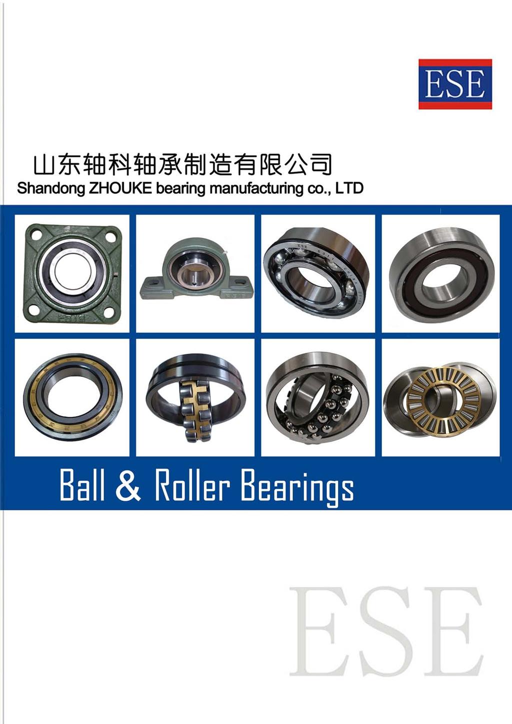
4 BALL & ROLLER BEARINGS POPULAR SIZE CAT. NO. 001ESE-1 VALUE & TECHNOLOGY


5 Standad ball and olle beaings Ball beaing units Locknuts Lockwashes
6 Intoduction This catalogue is pepaed to show most popula ball and olle beaings used in vaious applications. These beaings ae geneally available fom stock. As the technical infomation mentioned in this catalogue is limited, when moe detailed infomation is equied fo new design of application, it is ecommended that the ESE Geneal Catalogue is efeed. Fo touble fee opeation of the application, it is ecommended to keep the beaings in pope condition avoiding fom exteme high o low tempeatue, wet, contamination, hitting, dopping, etc.. Also pope handling and maintenance ae equied at mounting, egula inspection, ovehaul, and dismounting by the use of suitable tools, jigs and lubicant. *Fo impovements, as well as othe easons, the contents of this catalogue ae subject to change without pio notice. Repoduction is fobidden
7 Contents Technical section 1. Rolling beaing stuctues and types... A 1 2. Beaing intenal cleaance... A Beaing numbes... A Handling of beaings... A 22 Beaing specification tables Deep goove ball beaings d mm... B 2 Angula contact ball beaings d mm... B 16 Self-aligning ball beaings d mm... B 34 Cylindical olle beaings d mm... B 42 Tapeed olle beaings d mm... B 50 Spheical olle beaings d mm... B 70 Thust ball beaings d mm... B 88 Spheical thust olle beaings d mm... B 94 Ball beaing units d mm... B 98 Locknuts and lockwashes... B 132 Supplementay tables (Contents)... C 1 Poducts infomation (Contents)... D 1
8 1. Rolling beaing stuctues and types 1-1 Stuctue Rolling beaings (beaings heeinafte) nomally compise beaing ings, olling elements and a cage (see Fig. 1-1). Rolling elements ae aanged between inne and oute ings with a cage, which etains the olling elements in coect elative position, so they do not touch one anothe. With this stuctue, a smooth olling motion is ealized duing opeation. Beaings ae classified as follows, by the numbe of ows of olling elements: singleow, double-ow, o multi-ow (tiple- o fouow) beaings. Oute ing Ball Inne ing Cage Cup Rolle Cone Cage 2) Rolling element Rolling elements may be eithe balls o olles. Many types of beaings with vaious shapes of olles ae available. Ball Cylindical olle (L w 3D w ) 1) Long cylindical olle (3D w < L w <10D w, D w > 5 mm) 1) Needle olle (3D w < L w <10D w, D w 5 mm) 1) Tapeed olle (tapeed tapezoid) Convex olle (bael shape) Note 1) L w : olle length D w : olle diamete 3) Cage The cage guides the olling elements along the beaing ings, etaining the olling elements in coect elative position. Thee ae vaious types of cages including pessed, machined, molded, and pin type cages. Due to lowe fiction esistance than that found in full complement olle and ball beaings, beaings with a cage ae moe suitable fo use unde high speed otation. Deep goove ball beaing Tapeed olle beaing Shaft washe Ball Housing washe 1-2 Type The contact angle (α) is the angle fomed by the diection of the load applied to the beaing ings and olling elements, and a plan pependicula to the shaft cente, when the beaing is loaded. Thust ball beaing Cage Note) In thust beaings inne and oute ings and also called "shaft washe" and "housing washe" espectively; in tapeed olle beaings, the espective foms ae "cone" and "cup." Fig. 1-1 Beaing stuctue 1) Beaing ings The path of the olling elements is called the aceway; and, the section of the beaing ings whee the elements oll is called the aceway suface. In the case of ball beaings, since gooves ae povided fo the balls, they ae also efeed to as aceway gooves. The inne ing is nomally engaged with a shaft; and, the oute ing with a housing. α = 0 α α = 90 Beaings ae classified into two types in accodance with the contact angle (α). Radial beaings (0 α 45 )... designed to accommodate mainly adial load. Thust beaings (45 < α 90 )... designed to accommodate mainly axial load. Rolling beaings ae classified in Fig. 1-2, and chaacteistics of each beaing type ae descibed in Tables 1-1 to 1-8. A 1
9 1. Rolling beaing stuctues and types Radial beaing Radial ball beaing Deep goove ball beaing Angula contact ball beaing Fou-point contact ball beaing Self-aligning ball beaing Single-ow Single-ow Double-ow Matched pai o stack Double-ow Rolling beaing Radial olle beaing Cylindical olle beaing Needle olle beaing Tapeed olle beaing Spheical olle beaing Single-ow Double-ow Fou-ow Single-ow Double-ow Single-ow Double-ow Fou-ow Thust ball beaing Thust beaing Thust ball beaing Angula contact thust ball beaing Single diection Single diection with aligning seat washe Double diection Double diection with aligning seat washes Thust olle beaing Cylindical olle thust beaing Needle olle thust beaing Tapeed olle thust beaing Spheical thust olle beaing Single diection Double diection Fig. 1-2 Rolling beaings A 2
10 Table 1-1 Deep goove ball beaings Single-ow Double-ow Open type Shielded type Non-contact sealed type Contact sealed type Extemely light contact sealed type With locating snap ing Flanged type Maximum type ZZ 2RU 2RS 2RK 2RD NR Suitable fo exta-small o miniatue beaing 680, 690, 600, 620, 630, (ML), (OB)... Exta-small, miniatue beaing 6800, 6900, 16000, 6000, 6200, 6300, 6400 M6200 M The most popula types among olling beaings, widely used in a vaiety of industies. Radial load and axial load in both diections can be accommodated. Suitable fo opeation at high speed, with low noise and low vibation. Sealed beaings employing steel shields o ubbe seals ae filled with the appopiate volume of gease when manufactued. Beaings with a flange o locating snap ing attached on the oute ing ae easily mounted in housings fo simple positioning of housing location. In spite of having the same bounday dimensions as standad beaings, maximum type beaings have a highe load ating because a filling slot on each of the inne and oute ings, allows a geate numbe of balls to be inseted than do standad beaings. [ Recommended cages ] Pessed steel cage (ibbon types, snap type...single-ow, S type...double-ow), coppe alloy o phenolic esin machined cage, synthetic esin molded cage [ Main applications ] Automobile : font and ea wheels, tansmissions, electic devices Electic equipment : standad motos, electic appliances fo domestic use Othes : measuing instuments, intenal combustion engines, constuction equipment, ailway olling stock, cago tanspot equipment, agicultual equipment, equipment fo othe industial uses Oute ing chamfe Oute ing aceway Inne ing aceway Inne ing chamfe Pessed cage (ibbon type) Beaing width Beaing boe diamete Seal Pitch diamete of ball set Beaing outside diamete Beaing outside suface Goove shoulde Locating snap ing Snap ing goove Beaing boe suface Face Machined cage Face Pessed cage (S type) Beaing size (Refeence) Filling slot Unit mm Connotation Boe diamete Outside diamete Miniatue Unde 9 Exta-small Unde 10 9 o moe Small size 10 o moe 80 o less Medium size Lage size Exta-lage size Ove 800 A 3
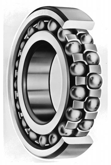
11 1. Rolling beaing stuctues and types Table 1-2 Angula contact ball beaings Single-ow Matched pai Double-ow Fo highspeed use Back-to-back aangement Face-to-Face aangement Tandem aangement With pessed cage With machined cage ACH DB DF DT (With filling slot) 7000, 7200, 7300, Contact angle B, 7200B, 7300B, 7400B C, 7000C, 7200C, 7300C... ACH900C, ACH000C Contact angle Contact angle 24 Beaing ings and balls possess thei own contact angle which is nomally 15, 30 o 40. Lage contact angle... highe esistance against axial load Smalle contact angle... moe advantageous fo high-speed otation Single-ow beaings can accommodate adial load and axial load in one diection. DB and DF matched pai beaings and double-ow beaings can accommodate adial load and axial load in both diections. DT matched pai beaings ae used fo applications whee axial load in one diection is too lage fo one beaing to accept. ACH type high speed beaings wee designed to contain moe balls than standad beaings by minimizing the ball diamete, to offe impoved pefomance in machine tools. Anglua contact ball beaings ae used fo high accuacy and high-speed opeation. Axial load in both diections and adial load can be accommodated by adapting a stuctue paiing two single-ow angula contact ball beaings back to back. Fo beaings with no filling slot, the sealed type is available. ZZ ( Shielded ) 2RS (Sealed) [ Recommended cages ] Pessed steel cage (conical type...single-ow : S type, snap type...double-ow), coppe alloy o phenolic esin machined cage, synthetic esin molded cage [ Main applications ] Single-ow : machine tool spindles, high fequency motos, gas tubines, centifugal sepaatos, font wheels of small size automobiles, diffeential pinion shafts Double-ow : hydaulic pumps, oots blowes, ai-compessos, tansmissions, fuel injection pumps, pinting equipment Oute ing back face Inne ing font face Oute ing font face Inne ing back face Contact angle Load cente Machined cage Stepped inne ing Ball and beaing ing ae not sepaable. Stand-out (δ 2 ) Counteboed oute ing Contact angles of ESE beaings (Refeence) Contact angle Supplementay code C CA AC A (Omitted) E B Pessed cage (conical type) Stand-out (δ 1 ) "G type" beaings ae pocessed (with flush gound) such that the stand-out tuns out to be δ 1 = δ 2. The matched pai DB, DF, and DT, o stack ae available. A 4
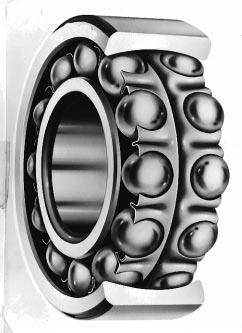
12 Table 1-3 Self-aligning ball beaings Cylindical boe Tapeed boe Sealed K (Tape 1 : 12) 120, , ,1300 extended inne ing type 2200,2300 2RS RS RS Spheical oute ing aceway allows self-alignment, accommodating shaft o housing deflection and misaligned mounting conditions. Tapeed boe design can be mounted eadily using an adapte. [ Recommended cages ] Pessed steel cage staggeed type... 12, 13, RS, RS snap type... 22, 23 [ Main applications ] Powe tansmission shaft of wood woking and spinning machines, plumme blocks Beaing width (B) Pessed cage (staggeed type) Beaing boe diamete (ød) Lage end of tapeed boe diamete (ød 1 ) Small end of tapeed boe diamete (ød) Pessed cage (snap type) Lockwashe Locknut Adapte sleeve Adapte assembly (d 1 = d + 1 B) 12 A 5
13 1. Rolling beaing stuctues and types Table 1-4 Cylindical olle beaings Single-ow Double-ow Fou-ow NU NJ NUP N NF NH NNU NN Mainly use on olling mill oll neck NU1000, NU200(R), NU300(R), NU400 NU2200(R), NU2300(R) NU3200, NU3300 Cylindical boe NNU4900 NN3000 Tapeed boe NNU4900K NN3000K (FC), (4CR) Since the design allowing linea contact of cylindical olles with the aceway povides stong esistance to adial load, this type is suitable fo use unde heavy adial load and impact load, as well as at high speed. N and NU types ae ideal fo use on the fee side : they ae movable in the shaft diection in esponse to changes in beaing position elative to the shaft o housing, which ae caused by heat expansion of the shaft o impope mounting. NJ and NF types can accommodate axial load in one diection ; and NH and NUP types can accommodate patial axial load in both diections. With sepaable inne and oute ing, this type ensues easy mounting. Due to thei high igidity, NNU and NN types ae widely used in machine tool spindles. [ Recommended cages ] Pessed steel cage (Z type), coppe alloy machined cage, pin type cage, synthetic esin molded cage [ Main applications ] Lage and medium size motos, taction motos, geneatos, intenal combustion engines, gas tubines, machine tool spindles, speed educes, cago tanspot equipment, and othe industial equipment Rib Ginding undecut Lubication goove Lubication hole Machined cage Rolle set boe diamete Rib Ginding undecut Pessed cage (Z type) Rolle set outside diamete Cente ib Rib Machined cage Cente ib Rib Loose ib Loose ib Space Guide ing Pin type cage (suitable Thust colla fo lage size beaings) Removal goove A 6
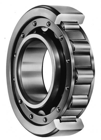
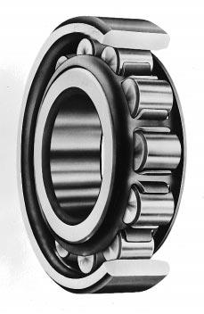
14 Table 1-5 Tapeed olle beaings Single-ow Double-ow Fou-ow 32900JR 32000JR 33000JR 33100JR Standad contact angle 30200JR 32200JR 33200JR 30300JR 32300JR Flanged type Intemediate Steep con- angle contact angle tact 30200CR 30300DJ 32200CR 30300DJR 30300CR 31300JR 32300CR Tapeed olles assembled in the beaings ae guided by the cone back face ib. The aceway sufaces of cone and cup and the olling contact suface of olles ae designed so that the espective apexes convege at a point on the beaing cente line. Single-ow beaings can accommodate adial load and axial load in one diection, and double-ow beaings can accommodate adial load and axial load in both diections. This type of beaing is suitable fo use unde heavy load o impact load. TDO type A A (46T) TDI type (45T) [ Recommended cages ] Pessed steel cage, synthetic esin molded cage, pin type cage Mainly used on olling mill oll neck (47T) Beaings ae classified into standad, intemediate and steep types, in accodance with thei coctact angle (α). The lage the contact angle is, the geate the beaing esistance to axial load. Since cup and cone assembly can be sepaated fom each othe, mounting is easy. Beaings designated by the suffix " J " and " JR " ae intechangeable intenationally. Items sized in inches ae still widely used. [ Main applications ] Automobile : font and ea wheels, tansmissions, diffeential pinion Othes : machine tool spindles, constuction equipment, lage size agicultual equipment, ailway olling stock speed eduction geas, olling mill oll necks and speed educes, etc Beaing width Cup angle Cup (oute ing) Cone (inne ing) Contact angle (α) Load cente Cup width Rolle small end face Cone font face ib Cup small inside diamete Cone width Stand-out Rolle lage end face Cone back face ib Pessed cage (window type) Font face Back face Back face Font face Anti-otation pin hole Lubication hole Lubication goove Double cup Pin type cage Oveall width of cones Cone space A 7 Double cone Oveall width of cups Cente ib Cup space with lubication holes and lubication goove Cone font face ib
15 1. Rolling beaing stuctues and types Table 1-6 Spheical olle beaings Cylindical boe Convex asymmetical olle type Convex symmetical olle type Tapeed boe R, RR RH, RHR RHA K o K R, 23000R (RH, RHA), 23100R (RH, RHA), 22200R (RH, RHA), 21300R (RH) 24000R (RH, RHA), 24100R (RH, RHA), 23200R (RH, RHA), 22300R (RH, RHA) Spheical olle beaings compising bael-shaped convex olles, double-ow inne ing and oute ing ae classified into thee types : R (RR), RH (RHR) and RHA, accoding to thei intenal stuctue. With the beaing designed such that the cicula ac cente of the oute ing aceway matches with the beaing cente, the beaing is self-aligning, insensitive to eos of alignment of the shaft elative to the housing, and to shaft bending. This type can accommodate adial load and axial load in both diections, which makes it especially suitable fo applications in which heavy load o impact load is applied. The tapeed boe type can be easily mounted / dismounted by using an adapte o withdawal sleeve. Thee ae two types of tapeed boes (tapeed atio) : 1 : 30 supplementay...suitable fo code K30 seies 240 and : 12 supplementay...suitable fo seies code K othe than 240 and 241. Lubication holes, a lubication goove and antiotation pin hole can be povided on the oute ing. Lubication holes and a lubication goove can be povided on the inne ing, too. [ Recommended cages ] Coppe alloy machined cage, pessed steel cage, pin type cage, synthetic esin molded cage [ Main applications ] Pape manufactuing equipment, speed educes, ailway olling stock axle jounals, olling mill pinion stands, table olles, cushes, shake sceens, pinting equipment, wood woking equipment, speed educes fo vaious industial uses, plumme blocks Oute ing Convex asymmetical olle Convex symmetical olle Convex symmetical olle Anti-otation pin hole Rib Inne ing Cente ib Machined cage sepaable pong type Guide ing Pessed cage Rib Guide ing Lage end of tapeed boe diamete (ød 1 ) Machined cage (pong type) Small end of tapeed boe diamete (ød) R, RR type RH, RHR type RHA type Lubication goove Lubication hole Adapte sleeve Lockwashe Locknut Adapte sleeve Locknut Lock plate Withdawal sleeve Oute ing guided machined cage (Boe diamete 180 mm) (Boe diamete 200 mm) (Fo shake sceen) A 8
16 Table 1-7 Thust ball beaings Single diection Double diection With flat back faces With spheical back face With aligning seat washe With flat back faces With spheical back faces With aligning seat washes U 53300U 53400U U 54300U 54400U This type of beaing compises washe-shaped ings with aceway goove and ball and cage assembly. Washes to be mounted on shafts ae called shaft washes (o inne ings); and, washes to be mounted into housings ae housing washes (o oute ings). Cental washes of double diection beaings ae mounted on the shafts. Single diection beaings accommodate axial load in one diection, and double diection beaings accommodate axial load in both diections. (Both of these beaings cannot accommodate adial loads.) Since beaings with a spheical back face ae self-aligning, it helps to compensate fo mounting eos. [ Recommended cages ] Pessed steel cage, coppe alloy o phenolic esin machined cage, synthetic esin molded cage [ Main applications ] Automobile king pins, machine tool spindles Beaing boe diamete (ød) Shaft washe Aligning suface adius Aligning suface cente height Machined cage Beaing outside diamete (ød ) Housing washe Beaing height Aligning housing washe Shaft washe back face Pessed cage Housing washe back face chamfe Raceway contact diamete Shaft washe back face chamfe Housing washe back face Aligning housing washe Washe height Aligning seat washe Cental washe Aligning seat washe A 9
17 1. Rolling beaing stuctues and types Table 1-8 Spheical thust olle beaings This type of beaing, compising bael-shaped convex olles aanged at an angle with the axis, is self-aligning due to spheical housing washe aceway; theefoe, shaft inclination can be compensated fo to a cetain degee. Geat axial load esistance is povided. This type can accommodate a small amount of adial load as well as heavy axial load. Nomally, oil lubication is employed. [ Recommended cage ] Coppe alloy machined cage [ Main applications ] Hydoelectic geneatos, vetical motos, popelle shafts fo ships, scew down speed educes, jib canes, coal mills, pushing machines, molding machines Convex olle Shaft washe Housing washe Machined cage Cage guide sleeve A 10
18 2. Beaing intenal cleaance Table 2-1 Radial intenal cleaance of deep goove ball beaings (cylindical boe) Nominal boe diamete d, mm ove up to C2 Cleaance CN C3 C4 C5 Unit µm max. max. max. max. max Remaks) 1. Fo measued cleaance, the incease of adial intenal cleaance caused by the measuement load should be added to the values in the above table fo coection. Amounts fo coection ae as shown below. Of the amounts fo cleaance coection in the C2 column, the smalle is applied to the minimum cleaance, the lage to the maximum cleaance. 2.Values typed in Italics ae based on the ESE standads. Nominal boe diamete d, mm ove up to Measuement load Amounts of cleaance coection, µm N C2 CN C3 C4 C Table 2-2 Radial intenal cleaance of exta-small / miniatue ball beaings Unit µm M1 M2 M3 M4 M5 M6 Cleaance code max. max. max. max. max. max. Cleaance Remak) Fo measued cleaance, the following amounts should be added fo coection. Measuement load Amounts of cleaance coection, µm N M1 M2 M3 M4 M5 M Exta-small ball beaing : 9 mm o lage in outside diamete and unde 10 mm in boe diamete Miniatue ball beaing : Unde 9 mm in outside diamete A 11
19 2. Beaing intenal cleaance Table 2-3 Axial intenal cleaance of matched pai angula contact ball beaings (measuement cleaance) 1) Unit µm Nominal boe diamete d, mm ove up to Contact angle : 15 C2 CN C2 max. max. max. Contact angle : 30 CN C3 C4 max. max. max Nominal boe diamete d, mm ove up to C2 max. Contact angle : 40 CN C3 max. max. C4 max Note 1) Including incease of cleaance caused by measuement load. A 12
20 Table 2-4 Radial intenal cleaance of double-ow angula contact ball beaings Unit µm Nominal boe diamete d, mm ove up to CD 2 max. Cleaance CD N max. CD 3 max A 13
21 2. Beaing intenal cleaance Table 2-5 Radial intenal cleaance of self-aligning ball beaings Nominal boe diamete d, mm ove up to C2 max. Cylindical boe beaing cleaance CN max. C3 max. C4 max. C5 max. C2 max. Tapeed boe beaing cleaance CN max. C3 max. C4 max. Unit µm C5 max Table 2-6 Radial intenal cleaance of electic moto beaings 1) Deep goove ball beaing Unit µm 2) Cylindical olle beaing Unit µm Nominal boe diamete d, mm ove up to Cleaance CM max. Nominal boe diamete d, mm ove up to Intechangeability CT max. Cleaance Non-intechangeability CM max. 10 1) Note 1) 10 mm is included. Remak) To adjust fo change of cleaance due to measuing load, use coection values shown in Table Note "Intechangeability" means intechangeable only among poducts (sub-units) of the same manufactue ; not with othes. A 14
22 A 15
23 2. Beaing intenal cleaance Table 2-7 Radial intenal cleaance of cylindical olle beaings and machined ing needle olle beaings (1) Cylindical boe beaing Unit µm Nominal boe diamete Cleaance d, mm C2 CN C3 C4 C5 ove up to max. max. max. max. max A 16
24 (2) Tapeed boe beaing Unit µm Nominal boe diamete d, mm ove up to C9 NA 1) max. C1 NA max. Non-intechangeable cleaance C2 NA max. CN NA max. C3 NA max. C4 NA max. C5 NA max Note 1) Cleaance C9NA is applied to tapeed boe cylindical olle beaings of JIS toleance classes 5 and 4. A 17
25 2. Beaing intenal cleaance Table 2-8 Radial intenal cleaance of spheical olle beaings (1) Cylindical boe beaing Unit µm Nominal boe diamete Cleaance d, mm C2 CN C3 C4 C5 ove up to max. max. max. max. max A 18
26 (2) Tapeed boe beaing Unit µm Nominal boe diamete Cleaance d, mm C2 CN C3 C4 C5 ove up to max. max. max. max. max A 19
27 2. Beaing intenal cleaance Table 2-9 Radial intenal cleaance of double / fou-ow and matched pai tapeed olle beaings (cylindical boe) Nominal boe diamete d, mm ove up to Unit µm Cleaance C1 C2 CN C3 C4 max. max. max. max. max A 20
28 3. Beaing numbes A beaing numbe is composed of a basic numbe and a supplementay code, denoting beaing specifications including beaing type, bounday dimensions, unning accuacy, and intenal cleaance. The figue below shows the geneal disignation system fo metic ball and olle beaings in diagam. Type Beaing seies code Dimension seies Boe diamete numbe Contact angle X X X X X X Angula contact ball beaing A (omitted) : 30, B : 40, C : 15 Tapeed olle beaing B (omitted) : 17, C : 20, D : 28 30', DJ : 28 48'39" Boe diamete d/5 Diamete seies Width seies (adial beaing) Height seies (thust beaing) (0) 1, NA NU NNU Type code Type (0) Angula contact ball beaing (double-ow) 1 Self-aligning ball beaing 2 Self-aligning ball beaing, Spheical olle beaing and Spheical thust olle beaing 3 Tapeed olle beaing 4 Deep goove ball beaing (double-ow) 5 Thust ball beaing, Angula contact ball beaing (double-ow) 6 Deep goove ball beaing (single-ow) 7 Angula contact ball beaing (single-ow) NA Needle olle beaing (single-ow, double-ow) N, NU Cylindical olle beaing (single-ow) NN, NNU Cylindical olle beaing (double-low) A 21
29 4. Handling of beaings 4. Handling of beaings 4-1 Geneal instuctions Since olling beaings ae moe pecisely made than othe machine pats, caeful handling is absolutely necessay. 1) Keep beaings and the opeating envionment clean. 2) Handle caefully. Beaings can be cacked and binelled easily by stong impact if handled oughly. 3) Handle using the pope tools. 4) Keep beaings well potected fom ust. Do not handle beaings in high humidity. Opeatos should wea gloves in ode not to soil beaings with pespiation fom thei hands. 5) Beaings should be handled by expeienced o well tained opeatos. 6) Set beaing opeation standads and follow them. Stoage of beaings Cleaning of beaings and thei adjoining pats Inspection of dimensions of adjoining pats and finish conditions Mounting Inspection afte mounting Dismounting Maintenance and inspection (peiodical inspection) Replenishment of lubicants 4-2 Stoage of beaings In shipping beaings, since they ae coveed with pope anti-coosion oil and ae wapped in antitanish pape, the quality of the beaings is guaanteed as long as the wapping pape is not damaged. If beaings ae to be stoed fo a long time, it is advisable that the beaings be stoed on shelves set highe than 30 cm fom the floo, at a humidity less than 65%, and at a tempeatue aound 20 C. Avoid stoage in places exposed diectly to the sun's ays o placing boxes of beaings against cold walls. 4-3 Beaing mounting Recommended pepaation pio to mounting 1) Pepaation of beaings Wait until just befoe mounting befoe emoving the beaings fom thei packaging to pevent contamination and ust. Since the anti-coosion oil coveing beaings is a highly capable lubicant, the oil should not be cleaned off if the beaings ae pe-lubicated, o when the beaings ae used fo nomal opeation. Howeve, if the beaings ae used in measuing instuments o at high otation speed, the anti-coosion oil should be emoved using a clean detegent oil. Afte emoval of the anti-coosion oil, beaings should not be left fo a long time because they ust easily. 2) Inspection of shafts and housings Clean up the shaft and housing to check whethe it has flaws o bus as a esult of machining. Be vey caeful to completely emove lapping agents (SiC, Al 2 O 3, etc.), casting sands, and chips fom inside the housing. Next, check that the dimensions, foms, and finish conditions of the shaft and the housing ae accuate to those specified on the dawing. The shaft diamete and housing boe diamete should de measued at the seveal points as shown in Fig. 4-1 and 4-2. Fig. 4-1 Measuing points on shaft diamete Fig. 4-2 Measuing points on housing boe diamete Futhemoe, fillet adius of shaft and housing, and the squaeness of shouldes should be checked. When using shaft and housing which have passed inspection, it is advisable to apply machine oil to each fitting suface just befoe mounting. A 22
30 4-3-2 Beaing mounting Mounting pocedues depend on the type and fitting conditions of beaings. Fo geneal beaings in which the shaft otates, an intefeence fit is applied to inne ings, while a cleaance fit is applied to oute ings. Fo beaings in which the oute ings otate, an intefeence fit is applied to the oute ings. Intefeence fitting is oughly classified as shown hee. The detailed mounting pocesses ae descibed in Tables 4-1 to 4-3. Intefeence fit of inne ings Beaings with cylindical boe Pess fit Applied to small size beaings with esticted intefeence. (Table 4-1) Shink fit Applied to beaings which allow heavy intefeence o to lage size beaings. (Table 4-2) Beaings with tapeed boe Mounting on tapeed shafts (Table 4-3) Mounting using sleeves (Table 4-3) Intefeence fit of oute ings Pess fit Most widely used method (Table 4-1) Cooling fit Beaings ae fit into housings by cooling them with dy ice, etc. In this method, pope ust-peventive teatment is equied, since moistue in the atmosphee adhees to beaings. Refeence Foce is necessay to pess fit o emove beaings The foce necessay to pess fit o emove inne ings of beaings diffes depending on the finish of shafts and how much intefeence the beaings allow. The standad values can be obtained by using the following equations. d 2 2 D i (Solid shafts) K a = 9.8ƒ k d eff B (4-1) (Hollow shafts) K a = 9.8ƒ k d eff B (4-2) 1 d 0 2 Remak) Fo meaning of symbols, see page A 24. d 2 2 D i 1 1 d 0 2 D i 2 d 2 A 23
31 4. Handling of beaings Table 4-1 Pess fit of beaings with cylindical boes Mounting methods (Hydaulic pump) Desciptions As shown in the Fig., a beaing should be mounted slowly with cae, by using a fixtue to apply foce evenly to the beaing. When mounting the inne ing, apply pessue to the inne ing only. Similaly, in mounting the oute ing, pess only the oute ing. Mounting fixtue Mounting fixtue (a) Using pess fit (the most widely used method) Inne ing pess fit Oute ing pess fit Inne ing pess fit (b) Using bolts and nuts scew hole should be povided at the shaft end (c) Using hammes only when thee is no altenative measue If intefeence is equied on both the inne and oute ing of nonsepaable beaings, use two kinds of fixtues as shown in the Fig. and apply foce caefully, as olling elements ae easily damaged. Be sue neve to use a hamme in such cases. Mounting fixtue Mounting fixtue Simultaneous pess fit of inne ing and oute ing In equations (4-1) and (4-2) in page A 23. K a : foce necessay fo pess fit o emoval N d eff : effective intefeence mm ƒ k : esistance coefficient Coefficient taking into consideation fiction between shafts and inne ings... efe to the table on the ight B : nominal inne ing width mm d : nominal inne ing boe diamete mm D i : aveage outside diamete of inne ing mm d 0 : hollow shaft boe diamete mm Value of esistance coefficient ƒ k Conditions Pess fitting beaings on to cylindical shafts Removing beaings fom cylindical shafts Pess fitting beaings on to tapeed shafts o tapeed sleeves Removing beaings fom tapeed shafts o tapeed sleeves Pess fitting tapeed sleeves between shafts and beaings Removing tapeed sleeves fom the space between shafts and beaings 4 6 ƒ k A 24
 Heating in an oil bath (Notes) Oil tempeatue should not be highe than 100 C, because beaings heated at highe than 120 C lose hadness.")
32 Table 4-2 Shink fit of cylindical boe beaings Shink fit Themomete Desciptions This method, which expands beaings by heating them in oil, has the advantage of not applying too much foce to beaings and taking only a shot time. (a) Heating in an oil bath (Notes) Oil tempeatue should not be highe than 100 C, because beaings heated at highe than 120 C lose hadness. Heating tempeatue can be detemined fom the boe diamete of a beaing and the intefeence by efeing to Fig Use nets o a lifting device to pevent the beaing fom esting diectly on the bottom of the oil containe. Since beaings shink in the adial diection as well as the axial diection while cooling down, fix the inne ing and shaft shoulde tightly with the shaft nut befoe shinking, so that no space is left between them. (b) Induction heate This photogaph shows a special machine fo fitting the inne ings of cylindi- olle beaings. cal Shink fit poves to be clean and effective since, by this method, the ing can be povided with even heat in a shot time using neithe fie no oil. When electicity is being conducted, the beaing itself geneates heat by its electical esistance, aided by the built-in exciting coil. Fo cylindical olle beaings used in oll necks of olling mills and ailway olling stock axle jounals, whee ings ae fequently mounted and dismounted, it is advisable fo ESE special induction heates (with automatic demagnetizes) to be used to fit inne ings. Expansion of boe diamete (µm) Tempeatue diffeence T = 90 C 80 C Boe diamete d Fig. 4-3 Heating tempeatue and expansion of inne ings 70 C 60 C 50 C 40 C 20 C 30 C 6 p 6 n 6 m 5 k 5 js 5 Remaks) 1. Thick solid lines show the maximum intefeence value between beaings (class 0) and shafts (6, p6, n6, m5, k5, js5) at nomal tempeatue. 2. Theefoe, the heating tempeatue should be selected to gain a lage "expansion of the boe diamete" than the maximum intefeence velues. When fitting class 0 beaings having a 90 mm boe diamete to m 5 shafts, this figue shows that heating tempeatue should be 40 C highe than oom tempeatue to poduce expansion lage than the maximum intefeence value of 48 µm. Howeve, taking cooling duing mounting into consideation, the tempeatue should be set 20 to 30 C highe than the tempeatue initially equied. A 25
33 4. Handling of beaings Table 4-3 Mounting beaings with tapeed boes Mounting methods Desciptions When mounting beaings diectly on tapeed shafts, povide oil holes and gooves on the shaft and inject high pessue oil into the space between the fitting sufaces (oil injection). Such oil injection can educe tightening toque of locknut by lessening fiction between the fitting sufaces. When exact positioning is equied in mounting a beaing on a shaft with no shoulde, use a clamp to help detemine the position of the beaing. q Locknut w Hydaulic nut (a) Mounting on tapeed shafts Locating beaing by use of a clamp q Locknut w Hydaulic nut (b) Mounting by use of an adapte When mounting beaings on shafts, locknuts ae geneally used. Special spannes ae used to tighten them. Beaings can also be mounted using hydaulic nuts. Special spanne When mounting tapeed boe spheical olle beaings, the eduction in the adial intenal cleaance which gadually occus duing opeation should be taken into consideation as well as the push-in depth descibed in Table 4-4. q Locknut w Hydaulic nut (c) Mounting by use of a withdawal sleeve e e Cleaance eduction can be measued by a thickness gage. Fist, stabilize the olle in the pope position and then inset the gage into the space between the olles and the oute ing. Be caeful that the cleaance between both olle ows and the oute ings is oughly the same (e e ). Since the cleaance may diffe at diffeent measuing points, take measuements at seveal positions. When mounting self-aligning ball beaings, leave enough cleaance to allow easy aligning of the oute ing. (d) Measuing cleaances A 26
34 Table 4-4 Mounting tapeed boe spheical olle beaings Nominal boe diamete d mm ove up to Reduction of Axial displacement, mm Minimum equied esidual cleaance, µm adial intenal cleaance µm 1/12 tape 1/30 tape CN C3 C4 cleaance cleaance cleaance max. max. max Remak) The values fo eduction of adial intenal cleaance listed above ae values obtained when mounting beaings with CN cleaance on solid shafts. In mounting beaings with C3 cleaance, the maximum value listed above should be taken as the standad. 4-4 Test un A tial opeation is conducted to insue that the beaings ae popely mounted. In the case of compact machines, otation may be checked by manual opeation at fist. If no abnomalities, such as those descibed below, ae obseved, then futhe tial opeation poceeds using a powe souce. Knocking... due to flaws o insetion of foeign matte on olling contact sufaces. Excessive toque (heavy)... due to fiction on sealing devices, too small cleaances, and mounting eos. Uneven unning toque... due to impope mounting and mounting eos. Fo machines too lage to allow manual opeation, idle unning is pefomed by tuning off the powe souce immediately afte tuning it on. Befoe stating powe opeation, it must be confimed that beaings otate smoothly without any abnomal vibation and noise. A 27
35 4. Handling of beaings Powe opeation should be stated unde no load and at low speed, then the speed is gadually inceased until the designed speed is eached. Duing powe opeation, check the noise, incease in tempeatue and vibation. If any of the abnomalities listed in Tables 4-5 and 4-6 ae found, opaation must be stopped, and inspection fo defects immediately conducted. The beaings should be dismounted if necessay. Table 4-5 Beaing noises, causes, and countemeasues Cyclic Not cyclic Noise types Causes Countemeasues Flaw noise Rust noise punching a ivet Binelling noise (unclea sien-like noise) Flaking noise [simila to a lage hammeing noise] Dit noise (an iegula sandy noise) Fitting noise [dumming o hammeing noise] Flaw noise, ust noise, flaking noise Squeak noise simila to noise when often head in cylindical olle beaings with gease lubication, especially in winte o at low tempeatues Flaw on eceway Rust on aceway Binelling on aceway Flaking on eceway Insetion of foeign matte Impope fitting o excessive beaing cleaance Flaws, ust and flaking on olling elements Impove mounting pocedue, cleaning method and ust peventive method. Replace beaing. Replace beaing. Impove cleaning method, sealing device. Use clean lubicant. Replace beaing. Review fitting and cleaance conditions. Povide peload. Impove mounting accuacy. Replace beaing. If noise is caused by impope lubication, a pope lubicant should be selected. In geneal, howeve, seious damage will not be caused by an impope lubicant if used continuously. Othes Abnomally lage metallic sound Abnomal load Incoect mounting Insufficient amount of o impope lubicant Review fitting, cleaance. Adjust peload. Impove accuacy in pocessing and mounting shafts and housings. Impove sealing device. Refill lubicant. Select pope lubicant. Table 4-6 Causes of and countemeasues fo adnomal tempeatue ise Causes Too much lubicant Insufficient lubicant Impope lubicant Abnomal load Impope mounting excessive fiction Reduce lubicant amount. Use gease of lowe consistency. Refill lubicant. Countemeasues Select pope lubicant. Review fitting and cleaance conditions and adjust peload. Impove accuacy on pocessing and mounting shaft and housing. Review fitting. Impove sealing device. Nomally, listening ods ae employed fo beaing noise inspections. The ESE Beaing Checke, which detects abnomalities though sound vibation, and the ESE AE Diagnosis System of Beaings, which utilizes acoustic emission fo abnomality detection, ae useful fo moe pecise inspection. In geneal, beaing tempeatue can be estimated fom housing tempeatue, but the most accuate method is to measue the tempeatue of oute ings diectly via lubication holes. Nomally, beaing tempeatue begins to ise gadually when opeation is just stating; and, unless the beaing has some abnomality, the tempeatue stabilizes within one o two hous. Theefoe, a apid ise in tempeatue o unusually high tempeatue indicates some abnomality. A 28
36 4-5 Beaing dismounting Afte dismounting beaings, handling of the beaings and the vaious methods available fo this should be consideed. If the beaing is to be disposed of, any simple method such as toch cutting can be employed. If the beaing is to be eused o checked fo the causes of its failue, the same amount of cae as in mounting should be taken in dismounting so as not to damage the beaing and othe pats. Since beaings with intefeence fits ae easily damaged duing dismounting, measues to pevent damage duing dismounting must be incopoated into the design. It is ecommended that dismounting devices be designed and manufactued, if necessay. It is useful fo discoveing the causes of failues when the conditions of beaings, including mounting diection and location, ae ecoded pio to dismounting. Dismounting method Tables 4-7 to 4-9 descibe dismounting methods fo intefeence fit beaings intended fo euse o fo failue analysis. The foce necessay to emove beaings can be calculated using the equations given on page A 23. Table 4-7 Dismounting of cylindical boe beaings Fixtues Inne ing dismounting methods (a) Dismounting by use of a pess Desciptions Non-sepaable beaings should be teated caefully duing dismounting so as to minimize extenal foce, which affects thei olling elements. The easiest way to emove beaings is by using a pess as shown in Fig.(a). It is ecommended that the fixtue be pepaed so that the inne ing can eceive the emoval foce. Figs.(b) and (c) show a dismounting method in which special tools ae employed. In both cases, the jaws of the tool should fimly hold the side of the inne ing. (b) Dismounting by use of special tools Removal jaws (c) Dismounting by use of special tools Fig.(d) shows an example of emoval by use of an induction heate: this method can be adapted to both mounting and dismounting of the inne ings of NU and NJ type cylindical olle beaings. The heate can be used fo heating and expanding inne ings in a shot time. (d) Dismounting using induction heate A 29
37 4. Handling of beaings Table 4-8 Dismounting tapeed boe beaings (a) Dismounting by use of a wedge Inne ing dismounting methods (b) Dismounting by use of oil pessue Desciptions Fig.(a) shows the dismounting of an inne ing by means of diving wedges into notches at the back of the labyinth. Fig.(b) shows dismounting by means of feeding high pessue oil to the fitting sufaces. In both cases, it is ecommended that a stoppe (ex. shaft nuts) be povided to pevent beaings fom suddenly dopping out. Fo beaings with an adapte sleeve, the following two methods ae suitable. As shown in Fig.(c), fix beaings with clamps, loosen locknuts, then hamme off the adapte sleeve. This method is mainly used fo small size beaings. Fig.(d) shows the method using hydaulic nuts. (c) Dismounting by use of clamps (d) Dismounting by use of hydaulic nuts Small size beaings with withdawal sleeves can be emoved by tightening locknuts as shown in Fig.(e). Fo lage size beaings, povide seveal bolt holes on locknuts as shown in Fig.(f), and tighten bolts. The beaings can then be emoved as easily as small size beaings. (e) Dismounting by use of locknuts (f) Dismounting by use of bolts (g) Dismounting by use of hydaulic nuts Fig.(g) shows the method using hydaulic nuts. Table 4-9 Dismounting of oute ings Oute ing dismounting methods Desciption To dismount oute ings with intefeence fits, it is ecommended that notches o bolt holes be povided on the shoulde of the housings. (a) Notches fo dismounting (b) Bolt holes and bolts fo dismounting A 30
38 4-6 Maintenance and inspection of beaings Peiodic and thoough maintenance and inspection ae indispensable to dawing full pefomance fom beaings and lengthening thei useful life. Besides, pevention of accidents and down time by ealy detection of failues though maintenance and inspection geatly contibutes to the enhancement of poductivity and pofitability Cleaning Befoe dismounting a beaing fo inspection, ecod the physical condition of the beaing, including taking photogaphs. Cleaning should be done afte checking the amount of emaining lubicant and collecting lubicant as a sample fo examination. A dity beaing should be cleaned using two cleaning pocesses, such as ough cleaning and finish cleaning. It is ecommended that a net be set on the bottom of cleaning containes. In ough cleaning, use bushes to emove gease and dit. Beaings should be handled caefully. Note that aceway sufaces may be damaged by foeign matte, if beaings ae otated in cleaning oil. Duing finish cleaning, clean beaings caefully by otating them slowly in cleaning oil. In geneal, neutal wate-fee light oil o keosene is used to clean beaings, a wam alkali solution can also be used if necessay. In any case, it is essential to keep oil clean by filteing it pio to cleaning. Apply anti-coosion oil o ust peventive gease on beaings immediately afte cleaning Inspection and analysis Befoe detemining that dismounted beaings will be eused, the accuacy of thei dimensions and unning, intenal cleaance, fitting sufaces, aceways, olling contact sufaces, cages and seals must be caefully examined, so as to confim that no abnomality is pesent. It is desiable fo skilled pesons who have sufficient knowledge of beaings to make decisions on the euse of beaings. Citeia fo euse diffes accoding to the pefomance and impotance of machines and inspection fequency. If the following defects ae found, eplace the beaing with a new one. Cacks and chips in beaing components Flaking on the aceway sufaces and the olling contact sufaces Othe failues of a seious degee 4-7 Methods of analyzing beaing failues It is impotant fo enhancing poductivity and pofitability, as well as fo accident pevention that abnomalities in beaings ae detected duing opeation. Repesentative detection methods ae descibed in the following section. 1) Noise checking Since the detection of abnomalities in beaings fom noises equies ample expeience, sufficient taining must be given to inspectos. Given this, it is ecommended that specific pesons be assigned to this wok in ode to gain this expeience. Attaching heaing aids o listening ods on housings is effective fo detecting beaing noise. 2) Checking of opeating tempeatue Since this method utilizes change in opeating tempeatue, its application is limited to elatively stable opeations. Fo detection, opeating tempeatues must be continuously ecoded. If abnomalities occu in beaings, opeating tempeatue not only incease but also change iegulaly. It is ecommended that this method be employed togethe with noise checking. 3) Lubicant checking This method detects abnomalities fom the foeign matte, including dit and metallic powde, in lubicants collected as samples. This method is ecommended fo inspection of beaings which cannot be checked by close visual inspection, and lage size beaings. A 31
39 ESE Beaing specification tables Contents Deep goove ball beaings.... B 2 Single-ow Open / shielded / sealed type.... B 6 Snap ing goove / lacating snap ing type.. B12 Exta-small, miniatue ball beaings Open / shielded / sealed type.... B14 Double-ow... B15 Angula contact ball beaings.... B16 Single-ow.... B24 Double-ow... B32 Self-aligning ball beaings.... B34 Open / sealed type.... B36 Adapte assemblies.... B40 Cylindical olle beaings... B42 Ball beaing units.... B 98 Pillow block type Set scew locking.... B104 Adapte locking.... B106 Thick section pillow block type.... B108 Rhombic-flanged type.... B110 Squae-flanged type.... B112 Round-flanged type with spigot joint... B114 Squae-flanged type with spigot joint... B116 Take-up type.... B118 Catidge type.... B120 Light duty.... B121 "Clean" seies.... B123 Pessed steel housing units.... B125 Ball beaings fo units Cylindical boe type (set scew locking).. B128 Tapeed boe type (adapte locking).. B130 Tapeed olle beaings.... B50 Metic seies.... B54 Inch seies.... B60 Locknuts and lockwashes.... B132 Locknuts.... B134 Lockwashes... B137 Spheical olle beaings.... B70 Spheical olle beaings.... B74 Adapte assemblies.... B82 Thust ball beaings... B88 Spheical thust olle beaings... B94 B 1


40
41 Deep goove ball beaings ESE Deep goove ball beaings ae available in a vaiety of sizes, and ae the most popula of all olling beaings. This type of beaing suppots adial load and a cetain degee of axial load in both diections simultaneously. Shielded / sealed type Simplifies sealing stuctue of applications. Geasing is not necessay because beaings ae pe-lubicated. Table 1 on the next page lists majo shielded and sealed beaing types and compaes thei pefomance. With locating snap ing Beaings with a locating snap ing can be fit to the housing easily, as the locating snap ing facilitates axial positioning. Exta-small ball beaings and miniatue ball beaings The open type is widely used. Also available ae the shielded / sealed type and the flanged type; the latte is easily positioned in the axial diection. Single-ow deep goove ball beaings Open type Boe diamete Boe diamete mm Exta-small ball beaings and miniatue ball beaings Boe diamete Shielded type 3 9 mm Sealed type With snap ing goove With locating snap ing mm Double-ow deep goove ball beaings (with filling slot) Boe diamete mm B 3
42 Deep goove ball beaings Table 1 Compaison of shielded and sealed beaing pefomance Shielded Sealed Type Non-contact type Non-contact type Contact type Extemely light contact type ZZ 2RU 2RS 2RK 2RD Chaacteistics (a) 1) (b) (c) (d) 2) (e) (f) (g) Fiction toque Small Small Lage Lage Small High speed pefomance Good Good Limited because of contact Good Gease sealing Good Bette than Bette than 2RU type fo Excellent Excellent popety ZZ type low-speed applications Dit esistance Good Bette than Bette than Excellent Excellent ZZ type 2RU type Wate esistance Economical Bette than ZZ type Good Excellent Bette than ZZ but infeio to 2RS, and 2RU types 2RK and 2RD types Opeating 30 to 110 C 30 to 100 C 30 to 110 C tempeatue 3) Notes) 1) Illustation (a) of the ZZ type shows the elatively small size beaing. 2) Illustation (d) of the 2RS type shows the elatively small size beaing. 3) The opeating tempeatue ange listed is fo the standad type. It can be widened by using a diffeent type of gease o sealing mateial.consult ESE fo details. Handling instuctions 1) The shielded / sealed type deep goove ball beaing and the deep goove ball beaing with a locating snap ing ae designed fo use with the inne ing otating. Consult ESE on use with the oute ing otating. 2) When the axial load is lage, make the shaft shoulde and housing shoulde lage than usual. (Refeing to the specification table, make the mounting dimension d a lage and make D a smalle.) B 4
43 Bounday dimensions Toleances Radial intenal cleaance The dimensions of standad seies ae as specified in JIS B Fo exta-small and miniatue ball beaings, special seies (ML) ae specified togethe with those descibed above. As specified in JIS B Deep goove ball beaings (except exta-small ball beaings and miniatue ball beaings)... as specified in JIS B 1520 (efe to Table 2-1 on p. A11.) Exta-small ball beaings and miniatue ball beaings... (efe to Table 2-2 on p. A11.) Deep goove ball beaings fo motos... (efe to Table 2-6 on p. A14.) Standad cages Pessed steel cage (supplementay code : //) Coppe alloy machined cage (supplementay code : FY) Remak : Fo cetain applications, stainless steel sheet pessed cages (YS) and polyamide molded cages (MG) may also be used. Application of standad cages Beaing seies Pessed cage Machined cage / Allowable misalignment Equivalent adial load (Single / double-ow) ad (8' 12') Dynamic equivalent adial load P = XF + YF a efe to the table on the ight fo values X and Y. Static equivalent adial load P 0 = 0.6F + 0.5F a when the value of P 0 < F, P 0 = F F a C 0 e F a F a F e F > e X Y X Y B 5
44 Single-ow deep goove ball beaings d mm B ød ød Z Z ZX RU RD RS RS ZZ ZZ ZZX 2RU 2RD 2RS 2RS Open Shielded Non-contact sealed Extemely light contact sealed Contact sealed Bounday dimensions d D B Basic load atings (kn) Limiting speeds (min 1 ) Gease lub. Oil lub. Open (RD, 2RD) (RS, 2RS) Open Z RU, 2RU C C 0 Z, ZZ Open Shielded ZZ Beaing No. Sealed 2RU 2RD 2RS (Refe.) Mass Open type (kg) ZZ 6900 ZZ 6000 ZZ 2RU 2RS 6200 ZZ 2RU 2RS 6300 ZZ 2RU 2RS 6801 ZZ 2RU 6901 ZZ 2RU ZZ 2RU 2RS 6201 ZZ 2RU 2RD 2RS 6301 ZZ 2RU 2RD 2RS 6802 ZZ 2RU 6902 ZZ 2RU ZZ 2RU 2RS 6202 ZZ 2RU 2RD 2RS 6302 ZZ 2RU 2RD 2RS 6803 ZZ 2RU 6903 ZZ 2RU ZZ 2RU 2RS 6203 ZZ 2RU 2RD 2RS 6303 ZZ 2RU 2RD 2RS ZZ 2RU 6904 ZZ 2RU ZZ 2RU 2RS 6204 ZZ 2RU 2RD 2RS 6304 ZZ 2RU 2RD 2RS Remak) Standad cage types used fo the above beaings ae descibed ealie in this section. B 6
45 d mm Bounday dimensions d D B Basic load atings (kn) Limiting speeds (min 1 ) Gease lub. Oil lub. Open (RD, 2RD) (RS, 2RS) Open RU, 2RU Z C C 0 Z, ZZ Open Shielded ZZ Beaing No. Sealed 2RU 2RD 2RS (Refe.) Mass Open type (kg) /22 2RS 62/22 2RS 63/22 2RS 6805 ZZ 2RU 6905 ZZ 2RU ZZ 2RU 2RS 6205 ZZ 2RU 2RD 2RS 6305 ZZ 2RU 2RD 2RS /28 ZZ 62/28 ZZ 2RS 63/28 ZZ 2RS 6806 ZZ 2RU 6906 ZZ 2RU ZZ 2RU 2RS 6206 ZZ 2RU 2RD 2RS 6306 ZZ 2RU 2RD 2RS /32 ZZ 2RS 62/32 ZZ 2RS 63/32 ZZ 2RS 6807 ZZ 2RU 6907 ZZ 2RU ZZ 2RU 2RS 6207 ZZ 2RU 2RD 2RS 6307 ZZ 2RU 2RD 2RS ZZ 2RU 6908 ZZ 2RU ZZ 2RU 2RS 6208 ZZ 2RU 2RD 2RS 6308 ZZ 2RU 2RD 2RS ZZ 2RU 6909 ZZ 2RU ZZ 2RU 2RS 6209 ZZ 2RU 2RD 2RS 6309 ZZ 2RU 2RD 2RS Remak) Standad cage types used fo the above beaings ae descibed ealie in this section. B 7
46 Single-ow deep goove ball beaings d 50 (70) mm B ød ød Z Z ZX RU RD RS RS ZZ ZZ ZZX 2RU 2RD 2RS 2RS Open Shielded Non-contact sealed Extemely light contact sealed Contact sealed Bounday dimensions d D B Basic load atings (kn) Limiting speeds (min 1 ) Gease lub. Oil lub. Open (RD, 2RD) (RS, 2RS) Open Z RU, 2RU C C 0 Z, ZZ Open Shielded ZZ Beaing No. Sealed 2RU 2RD 2RS (Refe.) Mass Open type (kg) ZZ 2RU 6910 ZZ 2RU ZZ 2RU 2RS 6210 ZZ 2RU 2RD 2RS 6310 ZZ 2RU 2RD 2RS ZZ 2RU 6911 ZZ 2RU ZZ 2RU 2RS 6211 ZZ 2RU 2RS 6311 ZZ 2RU 2RS ZZ 2RU 6912 ZZ 2RU ZZ 2RU 2RS 6212 ZZ 2RU 2RS 6312 ZZ 2RU 2RS ZZ 2RU 6913 ZZ 2RU ZZ 2RU 2RS 6213 ZZ 2RU 2RS 6313 ZZ 2RU 2RS ZZ 2RU 6914 ZZ 2RU ZZ 2RU 2RS Remak) Standad cage types used fo the above beaings ae descibed ealie in this section. B 8
47 d (70) 105 mm Bounday dimensions d D B Basic load atings (kn) Limiting speeds (min 1 ) Gease lub. Oil lub. Open (RD, 2RD) (RS, 2RS) Open RU, 2RU Z C C 0 Z, ZZ Open Shielded ZZ Beaing No. Sealed 2RU 2RD 2RS (Refe.) Mass Open type (kg) ZZ 2RU 2RS 6314 ZZ 2RU 2RS ZZ 2RU 6915 ZZ 2RU ZZ 2RU 2RS 6215 ZZ 2RU 2RS 6315 ZZ 2RU 2RS ZZ 2RU 6916 ZZ 2RU ZZ 2RS 6216 ZZ 2RS 6316 ZZ 2RS ZZ 2RU 6917 ZZ 2RU ZZ 2RS 6217 ZZ 2RS 6317 ZZX 2RS ZZ 2RU 6918 ZZ 2RU ZZ 2RS 6218 ZZ 2RS 6318 ZZX 2RS ZZ 2RU ZZX 2RU 2RS ZZX 2RS 6319 ZZX 2RS ZZ 2RU 6920 ZZ 2RU ZZ 2RS 6220 ZZX 2RS 6320 ZZX 2RS ZZ ZZX 2RS ZZX 2RS 6321 ZZX 2RS Remak) Standad cage types used fo the above beaings ae descibed ealie in this section. B 9
48 Single-ow deep goove ball beaings d 110 (160) mm B ød ød Z Z ZX RU RD RS RS ZZ ZZ ZZX 2RU 2RD 2RS 2RS Open Shielded Non-contact sealed Extemely light contact sealed Contact sealed Bounday dimensions d D B Basic load atings (kn) Limiting speeds (min 1 ) Gease lub. Oil lub. Open (RD, 2RD) (RS, 2RS) Open Z RU, 2RU C C 0 Z, ZZ Open Shielded ZZ Beaing No. Sealed 2RU 2RD 2RS (Refe.) Mass Open type (kg) ZZ 6922 ZZ ZZX 2RS 6222 ZZX 2RS 6322 ZZX 2RS ZZ 6924 ZZ ZZX 2RS 6224 ZZX 2RS 6324 ZZX ZZX 2RS 6226 ZZX 2RS 6326 ZZX ZZX 2RS 6228 ZZX 2RS 6328 ZZX ZZX 2RS 6230 ZZX Remak) Standad cage types used fo the above beaings ae descibed ealie in this section. B 10
49 d (160) 200 mm Bounday dimensions d D B Basic load atings (kn) Limiting speeds (min 1 ) Gease lub. Oil lub. Open (RD, 2RD) (RS, 2RS) Open RU, 2RU Z C C 0 Z, ZZ Open Shielded ZZ Beaing No. Sealed 2RU 2RD 2RS (Refe.) Mass Open type (kg) ZZX 2RS 6232 ZZX ZZX 6234 ZZX ZZX 6236 ZZX ZZX ZZX 6240 ZZX Remak) Standad cage types used fo the above beaings ae descibed ealie in this section. B 11
50 Single-ow deep goove ball beaings snap ing goove type locating snap ing type d mm 1 B a f ød ød ød 2 N With snap ing goove NR With locating snap ing With locating snap ing and one shield Bounday dimensions d D B 1 Basic load atings (kn) Limiting speeds (min 1 ) C C 0 Gease With snap Oil lub. lub. ing goove Beaing No. With locating snap ing Dimensions of locating snap ing D 2 max. a max. ƒ ±0.05 (Refe.) Mass (kg) N 6300N 6200NR 6300NR N 6301N 6201NR 6301NR N 6302N 6202NR 6302NR N 6303N 6203NR 6303NR N 6204N 6304N 6004NR 6204NR 6304NR /22N 60/22NR 62/22N 62/22NR 63/22N 63/22NR N 6205N 6305N 6005NR 6205NR 6305NR /28N 60/28NR 62/28N 62/28NR 63/28N 63/28NR N 6206N 6306N 6006NR 6206NR 6306NR /32N 60/32NR 62/32N 62/32NR 63/32N 63/32NR N 6207N 6307N 6007NR 6207NR 6307NR Remak) Standad cage types used fo the above beaings ae descibed ealie in this section. B 12
51 d mm Bounday dimensions d D B 1 Basic load atings (kn) Limiting speeds (min 1 ) C C 0 Gease With snap Oil lub. lub. ing goove Beaing No. With locating snap ing Dimensions of locating snap ing D 2 max. a max. ƒ ±0.05 (Refe.) Mass (kg) N 6208N 6308N 6008NR 6208NR 6308NR N 6209N 6309N 6009NR 6209NR 6309NR N 6210N 6310N 6010NR 6210NR 6310NR N 6211N 6311N 6011NR 6211NR 6311NR N 6212N 6312N 6012NR 6212NR 6312NR N 6213N 6313N 6013NR 6213NR 6313NR N 6214N 6314N 6014NR 6214NR 6314NR N 6215N 6315N 6015NR 6215NR 6315NR N 6216N 6316N 6016NR 6216NR 6316NR N 6217N 6317N 6017NR 6217NR 6317NR N 6218N 6318N 6018NR 6218NR 6318NR N 6219N 6319N 6019NR 6219NR 6319NR N 6220N 6020NR 6220NR N 6221N 6021NR 6221NR N 6222N 6022NR 6222NR N 6024NR N 6026NR Remak) Standad cage types used fo the above beaings ae descibed ealie in this section. B 13
52 Exta-small ball beaings, miniatue ball beaings d 3 9 mm B B 1 B 1 B ød ød ZZ ZZL 2RS Open Shielded Contact sealed Bounday dimensions d D B B 1 1 Basic load atings (kn) Limiting speeds (min 1 ) Gease lub. Oil lub. C C Open 0 ZZ, ZZL (2RS) Open Z, ZL Open Beaing No. Shielded ZZ, ZZL Sealed 2RS (Refe.) Mass (g) W693 ZZ ZZ 623 2RS ZZ 694 2RS ZZ ZZ 624 2RS ZZ ML5008 WML5008 ZZ ML5009 WML5009 ZZ ML5010 WML5010 ZZ W685 ZZ ZZ 695 2RS ZZ 625 2RS ZZ 635 2RS W686 ZZ W686 2RS ZZ 696 2RS ZZ ZZ 626 2RS W687 ZZ ZZ 607 2RS ZZ 627 2RS W688 ZZ W688 2RS ZZ 698 2RS ZZ 608 2RS ZZ 628 2RS ZZ W689 ZZ ZZ 699 2RS ZZ 609 2RS ZZ 629 2RS 20 B 14
53 Double-ow deep goove ball beaings d mm B ød ød Bounday dimensions d D B Basic load atings (kn) Limiting speeds (min 1 ) (Refe.) Mass Beaing No. C C 0 Gease lub. Oil lub. (kg) B 15


54
55 Angula contact ball beaings Single-ow angula contact ball beaings ESE Angula contact ball beaings ae suitable fo applications which equie high accuacy and good high-speed pefomance. This type of beaing is designed to cay a combined load. Boe diamete mm Single-ow angula contact ball beaings and matched pai angula contact ball beaings The standad contact angles ae 15, 30 and 40. They ae identified, espectively, by the supplementay codes "C", "A" (omitted) and "B". Beaing with a Contact angle α smalle contact angle ae moe suitable fo applications involving high-speed otation. Those with a lage contact angle featue supeio axial load esistance. Angula contact ball beaings ae often peloaded to enhance thei igidity and otating pefomance. Fo high-pecision matched pai angula contact ball beaings of class 5 o highe, which ae used in machine tools and othe pecision equipment, the standad peload is specified in thee levels: light (L), medium (M) and heavy (H). When this type of beaing is loaded adially, an axial component of foce is poduced. In this case, two beaings ae used togethe facing one anothe, o two o moe beaings ae matched and used. Tables 1 and 2 list the diffeent types of single-ow and matched pai/stack angula contact ball beaings and descibe thei chaacteistics. Double-ow angula contact ball beaings Boe diamete mm Double-ow angula contact ball beaings Consist of two single-ow angula contact ball beaings matched back-to-back, with inne and oute ings integated. Table 3 shows majo types and thei chaacteistics. B 17
56 Angula contact ball beaings Table 1 Single-ow angula contact ball beaings (with pessed cage) Single-ow angula contact ball beaings accommodate adial load and axial load in one diection. Beaings with a machined cage ae suitable fo highspeed applications. Refeence G-shaped beaing "G-shaped" beaings have a standout between the inne ing and oute ing on both sides that ae equal in size. This aangement is called "flush gound pocessing". These beaings can be matched in a vaiety of ways. (with machined cage) δ2 δ1 Table 2 Matched pai and stack angula contact ball beaings Back-to-back aangement (DB) a Caies adial load and axial load in both diections. Suitable fo applications involving moment loading because the distance between the load centes (a) is long. As fo the peloaded type, the cleaance is pe-adjusted so that beaings will be peloaded the pope amount when the inne ing is fixed with a nut. Face-to-face aangement (DF) Tandem aangement (DT) a Caies adial load and axial load in both diections. Has a smalle moment load accommodating capacity than the back-to-back aangement, because the distance between the load centes (a) is shote. As fo the peloaded type, the cleaance is pe-adjusted so that beaings will be peloaded the pope amount when the oute ings ae pessed togethe. Caies adial load and axial load in one diection. Suitable fo applications which involve a high degee of axial loading. Matched stack (DBD) (DFD) (DTD) (DBB) B 18
57 Table 3 Double-ow angula contact ball beaings Accommodates adial load and axial load in both diections. Also able to accommodate moment load. The 32 and 33 seies ae povided with a filling slot, while the 52 and 53 seies ae not. (with filling slot) 32, 33 (without filling slot) 52, and 33 seies : contact angle and 53 seies : contact angle 24 Infeio to single-ow and matched pai angula contact ball beaings in tems of high-speed and high accuacy pefomance. Shielded 52...ZZ, 53...ZZ Shealed RS, RS Shielded o sealed 52 and 53 seies beaings ae also available. Bounday dimensions Toleances The dimensions of standad seies ae as specified in JIS B As specified in JIS B ESE has established "special toleances" Special fo boe toleances diamete and (K5) outside diamete, Unit µm as listed in the table to the ight, to make it easy to poduce Single plane highpecision mean boe diamete matched Nominal boe stack beaings. ( d diamete mp ) o single plane mean outside Beaings which ae poduced based on these toleances diamete aedeviation identified ( Dby mp ) the supplementay code "K5." d Class 5 Class 4 ove up to uppe lowe uppe lowe Matched pai beaing axial intenal cleaance.... (efe to Table 2-3 on p. A 12.) Double-ow beaing adial intenal 50 cleaance... (efe 1 to Table on p. A 3 13.) Classes 5 and 4 beaings... as listed in the table below. Intenal cleaance Recommended fits With shaft Fit With housing Inne ing otation js 5 Oute ing otation Fixed side Fee side Oute ing otation Class 5 Class 4 Toleance class h 5 JS 6 H 6 M 5 js 4 h 4 JS 5 H 5 M 4 B 19
58 Angula contact ball beaings Standad cages Pessed steel cage (supplementay code : //) Coppe alloy machined cage (supplementay code : FY) Note) Machine tools ae geneally equipped with beaings that have a phenolic esin machined cage (FT). Beaings with a polyamide molded cage can also be used depending on the applications. Application of standad cages Beaing seies Pessed cage Machined cage B 7000 B 7040 B 70C 7000 C 7040 C B 7200 B 7220 B 7200 B 7240 B 72C 7200 C 7220 C 7200 C 7240 C B 7303 B 7320 B 7303 B 7340 B 73C 7303 C 7320 C 7303 C 7334 C B 7405 B 7409 B 7404 B 7418 B Allowable misalignment Single-ow ad (2'), double-ow... misalignment not allowed Equivalent adial load Single-ow and matched pai angula contact ball beaings Dynamic equivalent adial load P = XF + YF a Contact angle F a C 0 e Single-ow and tandem aangement Back-to-back and face-to-face aangement F a / F e F a / F > e F a / F e F a / F > e X Y X Y X Y X Y Note) When two single-ow angula contact ball beaings ae used facing one anothe, an axial component of foce is poduced unde adial load Static equivalent adial load P 0 = X 0 F + Y 0 F a In efeence to single-ow and tandem aangement beaings, when P 0 < F, Contact angle Single-ow and tandem aangement Back-to-back and face-to-face aangement X 0 Y 0 X 0 Y P 0 = F B 20
59 Equivalent adial load Double-ow angula contact ball beaings Dynamic equivalent adial load P = XF + YF a Contact angle e F a / F e F a / F > e X Y X Y (efeence) , 53 seies , 33 seies Static equivalent adial load P 0 = X 0 F + Y 0 F a Contact angle X 0 Y 0 (efeence) , 53 seies , 33 seies Remak) In angula contact ball beaings, slippage occus between the balls and aceways unde too small a load, causing smeaing to develop. Matched pai beaings may develop smeaing when the atio of the axial load to the adial load exceeds the value of e (F a / F > e), as listed in the specification table. Consult ESE when these beaings ae used unde the above conditions. [ Refeence ] Relationship between axial load and axial displacement Diagams (1) to (6) illustate the elationship between axial load and axial displacement. (1) 7000C (contact angle 15 ) (2) 7200C (contact angle 15 ) Boe dia. No. Amount of axial displacement (µm) , 07 Boe dia. No. 08, 09 10, 12 13, 16 21, 22, Amount of axial displacement (µm) , , 06, 07 08, 09 12, 14 13, 15 17, 18, , Axial load (kn) Axial load (kn) B 21
60 Angula contact ball beaings (3) 7000 (contact angle 30 ) (4) 7200 (contact angle 30 ) Boe dia. No. Boe dia. No Amount of axial displacement (µm) ,11 13,14 17,18 24,26 32,34 Amount of axial displacement (µm) , ,16 18,19, , Axial load (kn) Axial load (kn) (5) 7000B (contact angle 40 ) (6) 7200B (contact angle 40 ) Boe dia. No. 00 Boe dia. No Amount of axial displacement (µm) ,14 17,18 20,22 26 Amount of axial displacement (µm) ,16 18,20 22, Axial load (kn) Axial load (kn) B 22
61 B 23
62 Single-ow angula contact ball beaings d 10 (25) mm B 1 B 1 1 ød ød ød ød With machined cage With pessed cage Bounday dimensions d D B 1 Basic load atings (kn) Limiting speeds 1) (Refe.) With machined cage With pessed cage (min 1 ) Beaing 2) Mass Gease No. C C 0 C C 0 Oil lub. (kg) lub B B C B C B C B B C B C B C Notes 1) Rotation speed limits shown above ae applicable to machined cage beaings. Rotation speed limits of pessed cage beaings should be kept to unde 80 % of this value. Fo beaings with 15 contact angle, this figue is applied to the high pecision beaings anked highe than class 5, used with machined cage o molded cage. 2) B, C o no indication afte the beaing numbe indicates nominal contact angle of 40, 15 and 30 espectively. Remak) Standad cage types used fo the above beaings ae descibed ealie in this section. B 24
63 d (25) (45) mm Bounday dimensions d D B 1 Basic load atings (kn) Limiting speeds 1) (Refe.) With machined cage With pessed cage (min 1 ) Beaing 2) Mass Gease No. C C 0 C C 0 Oil lub. (kg) lub B 7205C B 7305C B C B 7206C B 7306C B C B 7207C B 7307C B C B 7208C B 7308C B C B 7209C Notes 1) Rotation speed limits shown above ae applicable to machined cage beaings. Rotation speed limits of pessed cage beaings should be kept to unde 80 % of this value. Fo beaings with 15 contact angle, this figue is applied to the high pecision beaings anked highe than class 5, used with machined cage o molded cage. 2) B, C o no indication afte the beaing numbe indicates nominal contact angle of 40, 15 and 30 espectively. Remak) Standad cage types used fo the above beaings ae descibed ealie in this section. B 25
64 Single-ow angula contact ball beaings d (45) (60) mm B 1 B 1 1 ød ød ød ød With machined cage With pessed cage Bounday dimensions d D B 1 Basic load atings (kn) Limiting speeds 1) (Refe.) With machined cage With pessed cage (min 1 ) Beaing 2) Mass Gease No. C C 0 C C 0 Oil lub. (kg) lub B 7309C B C B 7210C B 7310C B C B 7211C B B C B 7212C Notes 1) Rotation speed limits shown above ae applicable to machined cage beaings. Rotation speed limits of pessed cage beaings should be kept to unde 80 % of this value. Fo beaings with 15 contact angle, this figue is applied to the high pecision beaings anked highe than class 5, used with machined cage o molded cage. 2) B, C o no indication afte the beaing numbe indicates nominal contact angle of 40, 15 and 30 espectively. Remak) Standad cage types used fo the above beaings ae descibed ealie in this section. B 26
65 d (60) (85) mm Bounday dimensions d D B 1 Basic load atings (kn) Limiting speeds 1) (Refe.) With machined cage With pessed cage (min 1 ) Beaing 2) Mass Gease No. C C 0 C C 0 Oil lub. (kg) lub B B C B 7213C B B C B 7214C B B B C B B B C B B C B 7217C B 4.53 Notes 1) Rotation speed limits shown above ae applicable to machined cage beaings. Rotation speed limits of pessed cage beaings should be kept to unde 80 % of this value. Fo beaings with 15 contact angle, this figue is applied to the high pecision beaings anked highe than class 5, used with machined cage o molded cage. 2) B, C o no indication afte the beaing numbe indicates nominal contact angle of 40, 15 and 30 espectively. Remak) Standad cage types used fo the above beaings ae descibed ealie in this section. B 27
66 Single-ow angula contact ball beaings d (85) (105) mm B 1 B 1 1 ød ød ød ød With machined cage With pessed cage Bounday dimensions d D B 1 Basic load atings (kn) Limiting speeds 1) (Refe.) With machined cage With pessed cage (min 1 ) Beaing 2) Mass Gease No. C C 0 C C 0 Oil lub. (kg) lub B C B 7218C B B C B 7219C B B 7020C B 7220C B B Notes 1) Rotation speed limits shown above ae applicable to machined cage beaings. Rotation speed limits of pessed cage beaings should be kept to unde 80 % of this value. Fo beaings with 15 contact angle, this figue is applied to the high pecision beaings anked highe than class 5, used with machined cage o molded cage. 2) B, C o no indication afte the beaing numbe indicates nominal contact angle of 40, 15 and 30 espectively. Remak) Standad cage types used fo the above beaings ae descibed ealie in this section. B 28
67 d (105) 180 mm Bounday dimensions d D B 1 Basic load atings (kn) With machined cage With pessed cage C C 0 Limiting speeds (min 1 ) Beaing 1) Gease No. Oil lub. lub. (Refe.) Mass C C 0 (kg) B B B B B B B B B B B B B B B B 7332B B 7234B B B 7236B B 40.0 Note 1) B, C o no indication afte the beaing numbe indicates nominal contact angle of 40, 15 and 30 espectively. Remak) Standad cage types used fo the above beaings ae descibed ealie in this section. B 29
68 Single-ow angula contact ball beaings d mm B 1 B 1 1 ød ød ød ød With machined cage With pessed cage Bounday dimensions d D B 1 Basic load atings (kn) With machined cage With pessed cage C C 0 Limiting speeds (min 1 ) Beaing 1) Gease No. Oil lub. lub. (Refe.) Mass C C 0 (kg) B 7238B B B 7340B Note 1) B, C o no indication afte the beaing numbe indicates nominal contact angle of 40, 15 and 30 espectively. Remak) Standad cage types used fo the above beaings ae descibed ealie in this section. B 30
69 B 31
70 Double-ow angula contact ball beaings d mm B B ød ød ød ød Z RS ZZ 2RS Open Open Shielded Contact 32, 33 seies (With filling slot) 52, 53 seies (Without filling slot) sealed Bounday dimensions d D B Basic load atings (kn) Open Shielded-sealed Limiting speeds (min 1 ) Gease lub. Oil lub. Beaing No. C C 0 C C Open 0 Open Shielded Z, ZZ (RS, 2RS) Open Z ZZ Sealed 2RS (Refe.) Mass (kg) ZZ 2RS ZZ 2RS ZZ 2RS ZZ 2RS ZZ 2RS ZZ 2RS ZZ 2RS ZZ 2RS ZZ 2RS ZZ 2RS ZZ 2RS ZZ 2RS ZZ 2RS 1.42 Remak) Standad cage types used fo the above beaings ae descibed ealie in this section. B 32
71 d mm Bounday dimensions d D B Basic load atings(kn) Open Shielded-sealed Limiting speeds (min 1 ) Gease lub. Oil lub. Beaing No. C C 0 C C Open 0 Open Shielded Z, ZZ (RS, 2RS) Open Z ZZ Sealed 2RS (Refe.) Mass (kg) ZZ 2RS ZZ 2RS ZZ 2RS ZZ 2RS ZZ 2RS ZZ 2RS ZZ 2RS ZZ 2RS ZZ 2RS ZZ 2RS ZZ 2RS Remak) Standad cage types used fo the above beaings ae descibed ealie in this section. B 33
72
73 Self-aligning ball beaings ESE Self-aligning ball beaings have a spheical oute ing aceway, the cente of whose cuvatue meets that of the beaing itself, so that the inne ing, balls and cage continue to otate, aligning themselves if they have become misaligned within design limits. θ This type of beaing is suitable when the displacement of the centes aound which θ the shaft and housing otate and shaft deflection θ : Allowable aligning ae angle likely to occu. Beaings with a tapeed boe can easily be fit to the shaft with an adapte assembly. Self-aligning ball beaings Cylindical boe Boe diamete Tapeed boe mm Adapte assemblies Sealed boe Boe diamete mm Bounday dimensions Toleances Radial intenal cleaance Standad cages Allowable aligning angle The dimensions of standad seies ae as specified in JIS B As specified in JIS B 1514, class 0. As specified in JIS B (efe to Table 2-5 on p. A 14.) Staggeed type pessed steel cage application : all dimensional ange of 12, 13, RS and RS seies Snap type pessed steel cage application : all dimensional ange of 22 seies and those of No thu 2316 Coppe alloy machined cage (application : beaings of No thu 2320) 12 and 22 seies ad (2.5 ) 13 and 23 seies ad (3 ) RS and RS seies ad (1.5 ) Dynamic equivalent adial load P = XF + YF a F a / F e Static equivalent adial load P 0 = F + Y 0 F a F a / F > e X Y X Y 1 Y Y 2 B 35
74 Self-aligning ball beaings d mm B [Note] Potuding distance of balls C 1 ød ød ød Cylindical boe Sealed Tapeed boe Tape 1 /12 Balls of the following beaing potude by C 1 fom the beaing side. Beaing No C (appox.) Bounday dimensions d D B Basic load atings (kn) Open Sealed type Limiting speeds (min 1 ) Gease lub. Oil lub. Beaing No. Cylindical Sealed Tapeed boe type boe C C 0 C C 0 Open 2RS Open Open 2RS Open (Refe.)Mass(kg) Cylindical boe Tapeed boe RS RS RS RS RS RS K RS 2204K K RS 2304K K RS 2205K K RS 2305K K RS 2206K K RS 2306K K RS 2207K K RS 2307K Remak) Standad cage types used fo the above beaings ae descibed ealie in this section. B 36
75 d mm Bounday dimensions d D B Basic load atings (kn) Open Sealed type Limiting speeds (min 1 ) Gease lub. Oil lub. Beaing No. Cylindical Sealed Tapeed boe type boe C C 0 C C 0 Open 2RS Open Open 2RS Open (Refe.)Mass(kg) Cylindical boe Tapeed boe K RS 2208K K RS 2308K K RS 2209K K RS 2309K K RS 2210K K RS 2310K K RS 2211K K RS 2311K K RS 2212K K RS 2312K K RS 2213K K RS 2313K RS RS K RS 2215K K RS 2315K K RS 2216K K RS 2316K K RS 2217K K K K RS 2218K K K Remak) Standad cage types used fo the above beaings ae descibed ealie in this section. B 37
76 Self-aligning ball beaings d mm B [Note] Potuding distance of balls C 1 ød ød ød Cylindical boe Sealed Tapeed boe Tape 1 /12 Balls of the following beaing potude by C 1 fom the beaing side. Beaing No C (appox.) Bounday dimensions d D B Basic load atings (kn) Open Sealed type Limiting speeds (min 1 ) Gease lub. Oil lub. Beaing No. Cylindical Sealed Tapeed boe type boe C C 0 C C 0 Open 2RS Open Open 2RS Open (Refe.)Mass(kg) Cylindical boe Tapeed boe K RS 2219K K K K RS 2220K K K Remak) Standad cage types used fo the above beaings ae descibed ealie in this section. B 38
77 B 39
78 Adapte assemblies fo self-aligning ball beaings d mm B 2 A B 1 ød 2 ød b 1 ød e øk d 1 Bounday dimensions B 1 d 2 B 2 Bg. boe d Designations Beaing + adapte ass'y Mounting dimensions A K d e b Mass Bg. + adapte ass'y (kg) Adapte sleeve No. (Refe.) Locknut No K+ H204X 2204K+ H304X 1304K+ H304X A204X AN A304X AN A304X AN K+ H2304X A2304X AN K+ H205X 2205K+ H305X 1305K+ H305X A205X AN A305X AN A305X AN K+ H2305X A2305X AN K+ H206X 2206K+ H306X 1306K+ H306X A206X AN A306X AN A306X AN K+ H2306X A2306X AN K+ H207X 2207K+ H307X 1307K+ H307X A207X AN A307X AN A307X AN K+ H2307X A2307X AN K+ H208X 2208K+ H308X 1308K+ H308X A208X AN A308X AN A308X AN K+ H2308X A2308X AN K+ H209X 2209K+ H309X 1309K+ H309X A209X AN A309X AN A309X AN K+ H2309X A2309X AN K+ H210X 2210K+ H310X 1310K+ H310X A210X AN A310X AN A310X AN K+ H2310X A2310X AN10 B 40
79 d mm d 1 Bounday dimensions B 1 d 2 B 2 Bg. boe d Designations Beaing + adapte ass'y Mounting dimensions A K d e b Mass Bg. + adapte ass'y (kg) Adapte sleeve No. (Refe.) Locknut No K+ H211X 2211K+ H311X 1311K+ H311X A211X AN A311X AN A311X AN K+ H2311X A2311X AN K+ H212X 2212K+ H312X 1312K+ H312X A212X AN A312X AN A312X AN K+ H2312X A2312X AN K+ H213X 2213K+ H313X 1313K+ H313X A213X AN A313X AN A313X AN K+ H2313X A2313X AN K+ H215X 2215K+ H315X 1315K+ H315X A215X AN A315X AN A315X AN K+ H2315X A2315X AN K+ H216X 2216K+ H316X 1316K+ H316X A216X AN A316X AN A316X AN K+ H2316X A2316X AN K+ H217X 2217K+ H317X 1317K+ H317X A217X AN A317X AN A317X AN K+ H2317X A2317X AN K+ H218X 2218K+ H318X 1318K+ H318X A218X AN A318X AN A318X AN K+ H2318X A2318X AN K+ H219X 2219K+ H319X 1319K+ H319X A219X AN A319X AN A319X AN K+ H2319X A2319X AN K+ H220X 2220K+ H320X 1320K+ H320X A220X AN A320X AN A320X AN K+ H2320X A2320X AN20 B 41
80
81 Cylindical olle beaings Cylindical olle beaings ESE Cylindical olle beaings featue high adial load capacity because the olles and aceway ae in linea contact. These beaings ae suitable fo applications that involve heavy adial and impact loading. They ae also appopiate fo high-speed applications in that they can be machined vey accuately due to thei stuctue. Having a sepaable inne ing o oute ing, these beaings can be mounted and dismounted easily. Cylindical olle beaings Boe diamete mm NU N NJ NF NUP The NU and N types exhibit thei best pefomance when used as fee side beaings since they adjust to the shaft's axial movement, to a cetain extent, elative to the housing position. The NJ and NF types cay axial load in one diection, while the NUP type can cay a cetain degee of axial load in both diections. B 43
82 Cylindical olle beaings Bounday dimensions Toleances The dimensions of standad seies ae as specified in JIS B As specified in JIS B Toleances of olle set boe diamete F w and olle set outside diamete E w of intechangeable beaings ae as follows : Unit µm Nominal boe diamete d F W Rolle set boe diamete deviation E W Rolle set outside diamete deviation ove up to uppe lowe uppe lowe Remak) Intechangeable beaings have an inne ing with olles that can be matched with the oute ing, o an oute ing with olles that can be matched with the inne ing, without affecting pefomance. Radial intenal cleaance Cylindical boe and tapeed boe beaings... (efe to Table 2-7 on pp. A 16, 17.) Moto beaings... (efe to Table 2-6 on P. A 14.) Standad cages Pessed steel cage (supplementay code : //) Coppe alloy machined cage (supplementay code : FY) Coppe alloy machined cages without ivets (LY) ae also used fo some special puposes. Fo application ange, efe to Table 1. Allowable misalignment Equivalent adial load Allowable misalignment of single-ow cylindical olle beaings depends on beaing type and specification. Geneal values ae as follows : 1) When P / C is appox. 10% unde load of nomal use ad (2' 3') 2) When P / C is appox. 6% unde load lighte than 1) ad (4') When vey lage allowable misalignment is equied, consultese h. Dynamic equivalent adial load P = F Static equivalent adial load P 0 = F Allowable axial load Cylindical olle beaings with ibs, including loose ib and thust colle, on both inne and oute ings accommodate axial load to a cetain extent. (NJ and NF types accommodate load applied in one diection : NUP type in both diections.) B 44
83 Table 1 Application of standad cages Beaing seies Pessed cage Machined cage NU NU, NJ, NUP, NF NU, NJ, NUP NU, NJ, NUP, NF NU, NJ, NUP NU, NJ, NUP, NF B 45
84 Cylindical olle beaings d 20 (45) mm B ød øf w ød øf w øf w øe w øe w NU NJ NUP N NF 20 Bounday dimensions d D B 1 Basic load atings (kn) Limiting speeds (min 1 ) Gease Oil lub. lub. Beaing No. F W E W C C 0 NU NJ NUP N NF NU204 NJ NUP N NF NU2204 NJ NU304 NJ NUP N NF (Refe.) Mass NU (kg) NU NU1005 NU205 NJ NUP N NF NU2205 NJ NUP NU305 NJ NUP N NF NU2305 NJ NUP NU1006 NU206 NJ NUP N NF NU2206 NJ NUP NU306 NJ NUP N NF NU2306 NJ NUP NU406 NJ NF NU1007 NU207 NJ NUP N NF NU2207 NJ NUP NU307 NJ NUP N NF NU2307 NJ NUP NU407 NJ NF NU1008 NU208 NJ NUP N NF NU2208 NJ NUP NU308 NJ NUP N NF NU2308 NJ NUP NU408 NJ N NF NU1009 NU209 NJ NUP N NF NU2209 NJ NUP NU309 NJ NUP N NF Remaks) Standad cage types used fo the above beaings ae shown in Table 1 ealie in this section. Please note that basic load atings and otation speed limits shown above indicate the value applicable to machined cage. When beaings with pessed cage ae used, consult ESE. B 46
85 d (45) 80 mm Bounday dimensions d D B 1 Basic load atings (kn) Limiting speeds (min 1 ) Gease Oil lub. lub. Beaing No. F W E W C C 0 NU NJ NUP N NF (Refe.) Mass NU (kg) NU2309 NJ NUP NU409 NJ N NF NU1010 NU210 NJ NUP N NF NU2210 NJ NUP NU310 NJ NUP N NF NU2310 NJ NUP NU410 NJ NF NU1011 NU211 NJ NUP N NF NU2211 NJ NUP NU311 NJ NUP N NF NU2311 NJ NUP NU411 NJ N NF NU1012 NU212 NJ NUP N NF NU2212 NJ NUP NU312 NJ NUP N NF NU2312 NJ NUP NU412 NJ NUP N NF NU1013 NU213 NJ NUP N NF NU2213 NJ NUP NU3213 NU313 NJ NUP N NF NU2313 NJ NUP NU413 NJ NUP NF NU1014 NU214 NJ NUP N NF NU2214 NJ NUP NU314 NJ NUP N NF NU2314 NJ NUP NU414 NJ NUP N NF NU1015 NU215 NJ NUP N NF NU2215 NJ NUP NU315 NJ NUP N NF NU2315 NJ NUP NU415 NJ NUP N NF NU1016 NU216 NJ NUP N NF NU2216 NJ NUP NU316 NJ NUP N NF NU2316 NJ NUP NU416 NJ NUP N NF Remaks) Standad cage types used fo the above beaings ae shown in Table 1 ealie in this section. Please note that basic load atings and otation speed limits shown above indicate the value applicable to machined cage. When beaings with pessed cage ae used, consult ESE. B 47
86 Cylindical olle beaings d 85 (120) mm B ød øf w ød øf w øf w øe w øe w NU NJ NUP N NF Bounday dimensions d D B 1 Basic load atings (kn) Limiting speeds (min 1 ) Gease Oil lub. lub. Beaing No. F W E W C C 0 NU NJ NUP N NF (Refe.) Mass NU (kg) NU1017 NU217 NJ NUP N NF NU2217 NJ NUP NU317 NJ NUP N NF NU2317 NJ NUP NU417 NJ NUP N NF NU218 NJ NUP N NF NU2218 NJ NUP NU318 NJ NUP N NF NU2318 NJ NUP NU418 NJ NUP N NF NU219 NJ NUP N NF NU2219 NJ NUP NU319 NJ NUP N NF NU2319 NJ NUP NU419 NJ NU220 NJ NUP N NF NU2220 NJ NUP NU320 NJ NUP N NF NU2320 NJ NUP NU420 NJ NU221 NJ NUP N NF NU321 NJ NUP N NF NU222 NJ NUP N NF NU2222 NJ NUP NU322 NJ NUP N NF NU2322 NJ NU422 NJ NU224 NJ NUP N NF NU2224 NJ NUP Remaks) Standad cage types used fo the above beaings ae shown in Table 1 ealie in this section. Please note that basic load atings and otation speed limits shown above indicate the value applicable to machined cage. When beaings with pessed cage ae used, consult ESE. B 48
87 d (120) 200 mm Bounday dimensions d D B 1 Basic load atings (kn) Limiting speeds (min 1 ) Gease Oil lub. lub. Beaing No. F W E W C C 0 NU NJ NUP N NF (Refe.) Mass NU (kg) NU324 NJ NUP N NF NU2324 NJ NUP NU424 NJ NU1026 NU226 NJ NUP N NF NU2226 NJ NUP NU326 NJ NUP N NF NU2326 NJ NUP NU426 NJ NU1028 NU228 NJ NUP N NU2228 NJ NUP NU328 NJ NUP N NF NU2328 NJ NUP NU428 NJ NU1030 NU230 NJ NUP N NF NU2230 NJ NUP NU330 NJ NUP N NF NU2330 NJ NUP NU430 NJ NU232 NJ NUP N NF NU2232 NJ NUP NU332 NJ NUP N NU2332 NJ NUP NU234 NJ NUP N NU2234 NJ NUP NU334 NJ NUP N NU2334 NJ NUP NU236 NJ NUP N NU2236 NJ NUP NU336 NJ NUP N NU2336 NJ NUP NU238 NJ NUP N NU2238 NJ NUP NU338 NJ NUP N NU2338 NJ NUP NU240 NJ NUP N NU2240 NJ NUP NU340 NJ NUP N NU2340 NJ NUP 97.4 Remaks) Standad cage types used fo the above beaings ae shown in Table 1 ealie in this section. Please note that basic load atings and otation speed limits shown above indicate the value applicable to machined cage. When beaings with pessed cage ae used, consult ESE. B 49
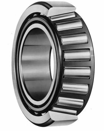
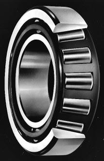
88
89 Tapeed olle beaings ESE Tapeed olle beaings ae designed such that cup, cone and olles have tapeed sufaces whose apexes convege at a common point on the beaing axis. Along with metic seies beaings, inch seies beaings ae also available. This type of beaing is suitable fo applications that involve heavy o impact loading. Tapeed olle beaings Able to cay adial and axial load in one diection simultaneously. Because an axial component of foce is poduced when this type of beaing is loaded adially, two beaings ae used togethe facing one anothe, o two o moe beaings ae matched and used. Thee ae the standad, medium and steep type which ae diffeent in contact angle size. Medium-tapeed metic seies beaings ae identified by the supplementay code "C" which is added as a suffix to beaing numbes. Beaings whose cup width, cup small inside diamete and contact angle ae detemined in accodance with ISO 355 specifications ae identified by the supplementay code "J" as a suffix. Cone assemblies and the cups of such beaings ae inte-changeable with those of beaings poduced aboad if the beaing numbes ae the same. Tapeed olle beaings Matic seies Boe diamete mm Inch seies (including J seies matic beaing) Boe diamete mm Cup width Contact angle(α) Cup small inside dia. ISO sub-unit specifications Note : When supplementay code "J" is added as a pefix (not a suffix) to beaing numbes (e.g. JHM720249/JHM720210), the beaings ae not designed accoding to ISO 355. Such beaings ae called "J seies metic tapeed olle beaings," and ae poduced accoding to special toleances. B 51
90 Tapeed olle beaings Bounday dimensions Metic single-ow tapeed olle beaings : as specified in JIS B Refeence JIS B 1512 specifies new dimension seies which ae based on ISO 355, as well as the conventional "3XX" dimension seies. These new dimension seies ae as follows : New dimension seies (1) Angle seies (3) Width seies Angle seies Contact angle α ove up to ' ' 15 59' ' 18 55' ' (2) Diamete seies Diamete seies ove D/ (d 0.77 ) up to B C D E F G Width seies ove T/ {(D d) 0.95 } up to B C D E Remaks : 1. Combine these seies symbols in the listed ode to make the dimension seies numbes. (ex. 2BC) 2. Beaing numbes consist of a dimension seies numbe and a boe diamete which is added as a suffix. (ex. 2BC080 : beaing boe diamete 80 mm) Toleances Metic seies single-ow tapeed olle beaings as specified in JIS B Inch seies tapeed olle beaings as specified in ABMA Section 19. J seies metic tapeed olle beaings the toleance is specified sepaately. Standad cage Pessed steel cage (supplementay code : //) (Some lage size beaings have a pin type cage (FP) instead.) Allowable misalignment Single-ow tapeed olle beaings : ad (3') (If the misalignment exceeds this angle size, ESE is eady to design special beaings to ode.) B 52
91 Equivalent adial load Single-ow tapeed olle beaings Dynamic equivalent adial load F when a e P = F F F when a > e P = 0.4F + Y 1 F a F Static equivalent adial load P 0 = 0.5F + Y 0 F a when P 0 < F, P 0 = F Double-ow o fou-ow tapeed olle beaings Dynamic equivalent adial load F when a e P = F + Y 2 F a F F when a > e P = 0.67F + Y 3 F a F Static equivalent adial load P 0 = F + Y 0 F a Remaks) 1. When two single-ow tapeed olle beaings ae used togethe facing one anothe, an axial component of foce is poduced unde adial load. 2. When the load is too small, slippage occus between the olles and aceways, causing smeaing to develop. This also occus to matched pai beaings when the atio of axial load to adial load exceeds the value e shown in the specification table (F a / F > e). Consult ESE on use of beaings unde such conditions. B 53
92 Tapeed olle beaings metic seies d mm T C 1 B ød ød Bounday dimensions d D T B C 1 Limiting speeds Basic load atings (Refe.) (Refe.) (kn) (min 1 ) Dimension Beaing No. Mass Gease seies to C C 0 Oil lub. (kg) lub. ISO R 30302JR 30203JR 32203JR 30303R FB DB DD JR 57008R 30204JR 32204JR 30304AJR 32304JR 3CC DB DD FD /22JR 3CC JR 33005JR 30205JR 32205JR 33205JR 30305DJR 4CC CE CC CD DE FB TR0506R 30305JR 32305JR FB FD /28JR 4CC JR 33006JR 30206JR 4CC CE DB JR 33206JR 30306DJR 3DC DE FB TRA0607R 30306JR 32306JR FB FD B 54
93 d 32 (55) mm Bounday dimensions d D T B C 1 Limiting speeds Basic load atings (Refe.) (Refe.) (kn) (min 1 ) Dimension Beaing No. Mass Gease seies to C C 0 Oil lub. (kg) lub. ISO /32JR 322/32 TR0608A 4CC FD JR 33007JR 30207JR 4CC CE DB JR 33207JR 30307DJR 3DC DE FB JR-1 TR0708-1R 32307JR 2FB FE JR 33008JR 33108JR 3CD BE CE JR 32208JR 33208JR 3DB DC DE DJR 30308JR TR0809AR 7FB FB JR 2FD JR 33009JR 33109JR 3CC CE CE JR 32209JR JR 3DB DC DE DJR 30309JR 32309JR 7FB FB FD JR 32010JR 33010JR 2BC CC CE JR 30210JR 32210JR 3CE DB DC JR 30310DJR 30310JR 3DE FB FB JR 2FD JR 32011JR 33011JR 2BC CC CE JR 30211JR 32211JR-1 3CE DB DC JR 30311DJR 3DE FB 1.59 B 55
94 Tapeed olle beaings metic seies d (55) 70 mm T C 1 B ød ød Bounday dimensions d D T B C 1 Limiting speeds Basic load atings (Refe.) (Refe.) (kn) (min 1 ) Dimension Beaing No. Mass Gease seies to C C 0 Oil lub. (kg) lub. ISO JR 32311JR 2FB FD JR 32012JR 33012JR 2BC CC CE JR 30212JR 32212JR 3CE EB EC JR 30312DJR 30312JR 3EE FB FB JR 2FD JR 32013JR 33013JR 2BC CC CE JR 30213JR 32213JR 3DE EB EC JR 30313DJR 30313JR 3EE GB GB JR 2GD JR 32014JR 33014JR 2BC CC CE JR 30214JR 32214JR 3DE EB EC JR 30314DJR 30314JR 3EE GB GB JR 2GD 4.50 B 56
95 d mm Bounday dimensions d D T B C 1 Limiting speeds Basic load atings (Refe.) (Refe.) (kn) (min 1 ) Dimension Beaing No. Mass Gease seies to C C 0 Oil lub. (kg) lub. ISO JR 32015JR 33015JR 2BC CC CE JR 30215JR 32215JR 3DE DB DC JR 30315DR 30315JR 3EE GB JR 2GD JR 32016JR 33016JR 2BC CC CE JR 30216JR 32216JR 3DE EB EC JR 30316DJR 30316JR 3EE GB GB JR 2GD JR 32017JR 33017JR 2BC CC CE JR 30217JR 32217JR 3DE EB EC JR 30317DJR 30317JR 3EE GB GB JR 2GD JR 32018JR 33018JR 2BC CC CE JR 30218JR 32218JR 3DE FB FC DR 30318JR 32318JR GB GD JR 33019JR 33119JR 4CC CE EE JR 32219JR 33219JR 3FB FC FE DJR 30319JR 32319JR 7GB GB GD 10.1 B 57
96 Tapeed olle beaings metic seies d 100 (120) mm T C 1 B ød ød Bounday dimensions d D T B C 1 Limiting speeds Basic load atings (Refe.) (Refe.) (kn) (min 1 ) Dimension Beaing No. Mass Gease seies to C C 0 Oil lub. (kg) lub. ISO JR 32020JR 33020JR 2CC CC CE JR 30220JR 32220JR 3EE FB FC JR 30320D FE JR 31320JR 32320JR 2GB GB GD JR 32021JR 33021JR 2CC DC DE JR 30221JR 32221JR 3EE FB FC JR 30321JR 31321JR 3FE GB GB JR 2GD JR 33022JR 33122JR 4DC DE EE JR 32222JR 30322JR 3FB FC GB JR 32322JR 7GB GD JR 32024JR 33024JR 2CC DC DE JR 30224JR 3FE FB 6.36 B 58
97 d (120) 200 mm Bounday dimensions d D T B C 1 Limiting speeds Basic load atings (Refe.) (Refe.) (kn) (min 1 ) Dimension Beaing No. Mass Gease seies to C C 0 Oil lub. (kg) lub. ISO JR 30324JR 31324JR 4FD GB GB JR 2GD JR 32026JR 33026JR 2CC EC EE JR 32226JR 30326JR 4FB FD GB JR 7GB JR 32028JR 33028JR 2CC DC DE JR 32228JR 30328JR 4FB FD GB JR 7GB JR 32030JR 33030JR 2DC EC EE JR 32230JR 30330JR 4GB GD GB JR 7GB JR 32032JR 30232JR 2DC EC GB JR 30332JR 4GD GB JR 32034JR 30234JR 3DC EC GB JR 30334JR 4GD GB JR 32036JR 30236JR 4DC FD GB JR 4GD JR 32038JR 30238JR 4DC FD GB JR 4GD JR 32040JR 30240JR 3EC FD GB JR 3GD 44.2 B 59
98 Tapeed olle beaings inch seies d (28.575) mm T C 1 B ød ød Bounday dimensions d D T B C 1 Basic load atings (kn) Limiting speeds (min 1 ) Gease C C 0 lub. Oil lub. Cone Beaing No. Cup (Refe.) Mass (kg) Cone Cup LM11749R LM LM11949 LM M12649 M LM12749 LM M12648 M LM72849 LM L44640R L S L44643R L R M86643R M HM88630 HM L44649R L R Remak) Inch seies tapeed olle beaings with boe diamete lage than 200 mm ae shown in catalogue "lage size ball & olle beaings," CAT. NO. 001ESE. B 60
99 d (28.575) mm Bounday dimensions d D T B C 2) 1 Basic load atings (kn) Limiting speeds (min 1 ) Gease C C 0 lub. Oil lub. Beaing No. 1) Cone Cup (Refe.) Mass (kg) Cone Cup M86647R M L45449 L M86649R M88043 M86610 M sp sp LM67048 LM M88046 M HM88542 HM HM88542 HM M88048 HM88547 HM89443 M88010 HM88510 HM sp LM48548 LM A HM88649 HM R sp sp L68149 L68149 L68110 L R HM88648 HM R HM89449 HM R sp sp JL69349 JL Notes 1) Beaings identified by pefix J featue special designed accuacy. 2) 'sp' means special chamfe shape. Remak) Inch seies tapeed olle beaings with boe diamete lage than 200 mm ae shown in catalogue "lage size ball & olle beaings," CAT. NO. 001ESE. B 61
100 Tapeed olle beaings inch seies d mm T C 1 B ød ød Bounday dimensions d D T B C 1) 1 Basic load atings (kn) Limiting speeds (min 1 ) Gease C C 0 lub. Oil lub. Cone Beaing No. Cup (Refe.) Mass (kg) Cone Cup sp LM29748 LM29710 LM29749 LM R R R HM HM HM801346X HM R 2735X A HM HM LM LM LM LM LM LM R R A 362A HM HM HM HM HM HM HM HM Note 1) 'sp' means special chamfe shape. Remak) Inch seies tapeed olle beaings with boe diamete lage than 200 mm ae shown in catalogue "lage size ball & olle beaings," CAT. NO. 001ESE. B 62
101 d mm Bounday dimensions d D T B C 1 Basic load atings (kn) Limiting speeds (min 1 ) Gease C C 0 lub. Oil lub. Beaing No. 1) Cone Cup (Refe.) Mass (kg) Cone Cup R A A 354A HM HM HM HM HM HM HM HM HM HM CR CR HM HM LM LM LM LM LM LM LM LM LM503349R LM A 354A 359S 354A A M HM A M HM A 382A X HM HM S 362A HM HM JLM JLM A JM JM JHM JHM A Note 1) Beaings identified by pefix J featue special designed accuacy. Remak) Inch seies tapeed olle beaings with boe diamete lage than 200 mm ae shown in catalogue "lage size ball & olle beaings," CAT. NO. 001ESE. B 63
102 Tapeed olle beaings inch seies d mm T C 1 B ød ød Bounday dimensions d D T B C 1 Basic load atings (kn) Limiting speeds (min 1 ) Gease C C 0 lub. Oil lub. Cone Beaing No. Cup (Refe.) Mass (kg) Cone Cup LM LM A A 362A 28580R AX 382A HM HM X 55200CR C S 362A R X LM LM HM HM C S 552A Remak) Inch seies tapeed olle beaings with boe diamete lage than 200 mm ae shown in catalogue "lage size ball & olle beaings," CAT. NO. 001ESE. B 64
103 d mm Bounday dimensions d D T B C 1 Basic load atings (kn) Limiting speeds (min 1 ) Gease C C 0 lub. Oil lub. Beaing No. 1) Cone Cup (Refe.) Mass (kg) Cone Cup JLM JLM JM JM A JH JH A A 387A 382A 387AS 382A S 382A X X C A 382A H H A H913842R H A JLM JM JH JLM JM JH A 394A 395S 394A HM HM HH HH Note 1) Beaings identified by pefix J featue special designed accuacy. Remak) Inch seies tapeed olle beaings with boe diamete lage than 200 mm ae shown in catalogue "lage size ball & olle beaings," CAT. NO. 001ESE. B 65
104 Tapeed olle beaings inch seies d (76.200) mm T C 1 ød B ød Bounday dimensions d D T B C 1 Basic load atings (kn) Limiting speeds (min 1 ) Gease C C 0 lub. Oil lub. Beaing No. 1) Cone Cup (Refe.) Mass (kg) Cone Cup A 399AS H A 394A H H H R X H913849R H JLM JLM JM JM R A H H H H JLM JLM JM JM AX 492A R A R Note 1) Beaings identified by pefix J featue special designed accuacy. Remak) Inch seies tapeed olle beaings with boe diamete lage than 200 mm ae shown in catalogue "lage size ball & olle beaings," CAT. NO. 001ESE. B 66
105 d (76.200) ( ) mm Bounday dimensions d D T B C 1 Basic load atings (kn) Limiting speeds (min 1 ) Gease C C 0 lub. Oil lub. Beaing No. 1) Cone Cup (Refe.) Mass (kg) Cone Cup SR R LM LM HH HH JM JM A A 47686R 47620A HM HM R 572X 580R R AR JM JM JHM JHM R A HM HM A A HM HM R HM HM JM JM LL A LL XE JM JM JHM JHM Note 1) Beaings identified by pefix J featue special designed accuacy. Remak) Inch seies tapeed olle beaings with boe diamete lage than 200 mm ae shown in catalogue "lage size ball & olle beaings," CAT. NO. 001ESE. B 67
106 Tapeed olle beaings inch seies d ( ) mm T C 1 B ød ød Bounday dimensions d D T B C 1 Basic load atings (kn) Limiting speeds (min 1 ) Gease C C 0 lub. Oil lub. Beaing No. 1) Cone Cup (Refe.) Mass (kg) Cone Cup R 854 HH HH R L521949R L R LM LM JM JM R HH HH HM HM HH HH JHM JHM JM JM JM JM L L JHM JHM Note 1) Beaings identified by pefix J featue special designed accuacy. Remak) Inch seies tapeed olle beaings with boe diamete lage than 200 mm ae shown in catalogue "lage size ball & olle beaings," CAT. NO. 001ESE. B 68
107 B 69

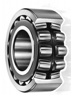
108
109 Spheical olle beaings ESE Spheical olle beaings featue a lage load ating capacity and self-aligning capability. This type of beaing is suitable fo low-o mediumspeed applications which involve heavy o impact loading. These beaings ae divided into R, RR, RH, RHR and RHA types, which diffe in intenal stuctue. (efe o Table 1.) Each type can be poduced with a cylindical boe o tapeed boe. Beaing with a tapeed boe can be fit and emoved easily using an adapte assembly o withdawal sleeve. The ate of tape is equivalent among all beaing seies. 240 and 241 seies...1 : 30 (supplementay code "K30") Othes...1 : 12 (supplementay code "K") Table 1 Spheical olle beaings : types and stuctues Spheical olle beaings Cylindical boe Tapeed boe Boe diamete mm Adapte assemblies Boe diamete mm Stuctue R, RR type* RH, RHR type RHA type Rolle Convex asymmetical olle Convex symmetical olle Convex symmetical olle Cage Coppe alloy pong type machined cage *(excl. 240 and 241 seies) Pessed steel cage Coppe alloy integal type machined cage With cente ib Without cente ib (guide ing) Without cente ib (guide ing) Inne ing (with o without ib) With ibs on both sides (to pevent olles fom falling) *(excl. 240 and 241 seies) Without ibs on both sides With ibs on both sides (to pevent olles fom falling) Chaacteistics Supeio to RH and RHA types in high-speed pefomance. The load ating capacity is lage than that of R type. (Thee ae some exceptional cases due to diffeent inteio specifications.) * Some 240 o 241 seies R type beaings have a pessed cage. Some of them ae povided with an inne ing which does not have ibs. Spheical olle beaings fo shake sceens These beaings consist of convex asymmetic olles and a pong type, coppe alloy, oute ing guided, machined cage. This cage possesses optimum chaacteistics fo use with shake sceens. The beaings most commonly used with shake sceens ae 223 seies spheical olle beaings. They ae identified by the supplementay code ROVSW502. The oute ing outside diamete toleance of these beaings is held to a small allowable vaiation. B 71
110 Spheical olle beaings Beaings with lubication holes and a lubication goove Oute ings can be povided with lubication Inne ings can also be povided with holes, a lubication goove and an anti-otation pin hole. (Specifications ae given in goove. lubication holes and a lubication Table 4.) Table 2 Supplementay codes fo identification of beaings with lubication holes, lubication goove and anti-otation pin hole (oute ing) With lubication holes and lubication goove Supplementay code With lubication holes, lubication goove and anti-otation pin hole Numbe of lubication holes W33 W3N 3 W33A W3NA 4 W3NB 5 W33C W3NC 6 W3ND 7 W33T 8 Hole layout 3 equally spaced positions 1) 4 equally spaced positions 6 equally spaced positions 2) 6 equally spaced positions 8 equally spaced positions 2) 8 equally spaced positions Notes 1) 4 o 6 holes ae povided in smalle size beaings.consult ESE. 2) One hole is used fo the anti-otation pin. Supplementay code Table 4 Lubication hole and lubication goove dimensions Boe diamete numbe Nominal boe diamete d 239 d 0 w h 230 d 0 w h 240 d 0 w h 231 d 0 w h Table 3 Supplementay codes fo identification of beaings with lubication holes and / o lubication goove Numbe of lubication holes Inne ing Lubication goove Numbe of lubicaiton holes Oute ing Lubication goove W W W d 0 w h 222 d 0 w h h 232 w d 0 w h ød d 0 w h Unit mm 223 d 0 w h / B 72
111 Bounday dimensions Toleances Radial intenal cleaance Standad cages Allowable aligning angle As specified in JIS B As specified in JIS B 1514, class 0. As specified in JIS B (efe to Table 2-8 on pp. A 18, 19.) Refe to Table 5. Refe to Table 5. (veies depending on beaing seies.) Equivalent adial load Remak) Dynamic equivalent adial load F when a e P = F + Y 1 F a F when a > e P = 0.67F + Y 2 F a F Static equivalent adial load P 0 = F + Y 0 F a If the atio of axial load to adial load exceeds the value e given in the specification table (F a / F > e), slippage occus between olles in ows that ae not axial-loaded and the aceway. This may cause smeaing, especially when the beaing is lage. Consult ESE on the use of beaings unde such conditions. F Table 5 Application of standad cages and allowable aligning angle Beaing seies 239 R 230 R RH RHA 240 R RH RHA 231 R RH RHA 241 R RH RHA 222 R(RR) RH(RHR) RHA 232 R RH RHA 213 R RH 223 R(RR) RH(RHR) RHA Standad cages Pessed cage Machined cage 23930R 239/500R 23038R 230/500R 23022RH 23036RH 23038RHA 23096RHA 24038R 240/500R 24024RH 24036RH 24038RHA 24096RHA 23136R 231/500R 23122RH 23134RH 23136RHA 23196RHA 24136R 241/500R 24122RH 24134RH 24136RHA 24196RHA 22232RR 22272R 22205RHR 22230RH 22232RHA 22260RHA 23232R 232/500R 23218RH 23230RH 23232RHA 23296RHA 21328R 21322R 21311RH 21322RH 22328R 22360R 22308RHR 22326RH 22328RHA 22356RHA Allowable aligning angle ad (1.5 ) ad (1.5 ) ad (2 ) ad (1.5 ) ad (2.5 ) ad (1.5 ) ad (2.5 ) ad (1 ) ad (2 ) B 73
112 Spheical olle beaings d mm R, RR RH, RHR RHA B B B ød ød ød ød ød ød ød ød ød Cylindical boe Tapeed boe Cylindical boe Tapeed boe Cylindical boe Tapeed boe Bounday dimensions d D B Basic load atings (kn) Limiting speeds (min 1 ) C C Gease 0 lub. Oil lub. Cylindical boe Beaing No. Tapeed boe (Refe.) Mass (kg) Cylindical boe Tapeed boe RHR 22205RHRK RHR 21306RH 22206RHRK 21306RHK RHR 21307RH 22207RHRK 21307RHK RHR 21308RH 22308RHR 22208RHRK 21308RHK 22308RHRK RHR 21309RH 22309RHR 22209RHRK 21309RHK 22309RHRK RHR 21310RH 22310RHR 22210RHRK 21310RHK 22310RHRK RHR 21311RH 22311RHR 22211RHRK 21311RHK 22311RHRK RHR 21312RH 22312RHR 22212RHRK 21312RHK 22312RHRK RHR 21313RH 22313RHR 22213RHRK 21313RHK 22313RHRK RHR 21314RH 22314RHR 22214RHRK 21314RHK 22314RHRK RHR 21315RH 22315RHR 22215RHRK 21315RHK 22315RHRK RHR 21316RH 22316RHR 22216RHRK 21316RHK 22316RHRK Remak) Standad cage types used fo the above beaings ae shown in Table 5 ealie in this section. B 74
113 d 85 (150) mm Bounday dimensions d D B Basic load atings (kn) Limiting speeds (min 1 ) C C Gease 0 lub. Oil lub. Cylindical boe Beaing No. Tapeed boe (Refe.) Mass (kg) Cylindical boe Tapeed boe RHR 21317RH 22317RHR 22217RHRK 21317RHK 22317RHRK RHR 23218RH 21318RH 22218RHRK 23218RHK 21318RHK RHR 22318RHRK RHR 21319RH 22319RHR 22219RHRK 21319RHK 22319RHRK RH 22220RHR 22220RHRK 23220RH 23220RHK RH 22320RHR 21320RHK 22320RHRK RH 23122RH 24122RH 23022RHK 23122RHK 24122RHK RHR 23222RH 21322RH 22222RHRK 23222RHK 21322RHK RHR 22322RHRK RH 24024RH 23124RH 23024RHK 24024RHK RHK RH 22224RHR 23224RH 24124RHK RHRK 23224RHK RHR 22324RHRK RH 24026RH 23126RH 23026RHK 24026RHK RHK RH 22226RHR 23226RH 24126RHK RHRK 23226RHK RHR 22326RHRK RH 24028RH 23128RH 23028RHK 24028RHK RHK RH 22228RHR 23228RH 24128RHK RHRK 23228RHK R 22328RH 22328RK 22328RHK R 23930RK Remak) Standad cage types used fo the above beaings ae shown in Table 5 ealie in this section. B 75
114 Spheical olle beaings d (150) (180) mm R, RR RH, RHR RHA B B B ød ød ød ød ød ød ød ød ød Cylindical boe Tapeed boe Cylindical boe Tapeed boe Cylindical boe Tapeed boe Bounday dimensions d D B Basic load atings (kn) Limiting speeds (min 1 ) C C Gease 0 lub. Oil lub. Cylindical boe Beaing No. Tapeed boe (Refe.) Mass (kg) Cylindical boe Tapeed boe RH 24030RH 23130RH 23030RHK 24030RHK RHK RH 22230RHR 23230RH 24130RHK RHRK 23230RHK R 22330RHA 22330RK 22330RHAK R 23032RH 24032RH 23932RK 23032RHK 24032RHK RH 24132RH 22232R 23132RHK 24132RHK RK RHA 23232R 23232RHA 22232RHAK 23232RK 23232RHAK R 22332RHA 22332RK 22332RHAK R 23034RH 24034RH 23934RK 23034RHK 24034RHK RH 24134RH 22234R 23134RHK 24134RHK RK RHA 23234R 23234RHA 22234RHAK 23234RK 23234RHAK R 22334RHA 22334RK 22334RHAK R 23036RH 24036RH 23936RK 23036RHK 24036RHK Remak) Standad cage types used fo the above beaings ae shown in Table 5 ealie in this section. B 76
115 d (180) (220) mm Bounday dimensions d D B Basic load atings (kn) Limiting speeds (min 1 ) C C Gease 0 lub. Oil lub. Cylindical boe Beaing No. Tapeed boe (Refe.) Mass (kg) Cylindical boe Tapeed boe R 23136RHA 24136R 23136RK 23136RHAK 24136RK RHA 22236R 22236RHA 24136RHAK RK 22236RHAK R 23236RHA 22336R 23236RK 23236RHAK 22336RK RHA 22336RHAK R 23038R 23038RHA 23938RK 23038RK 23038RHAK R 24038RHA 23138R 24038RK RHAK RK RHA 24138R 24138RHA 23138RHAK 24138RK RHAK R 22238RHA 23238R 22238RK 22238RHAK 23238RK RHA 22338R 22338RHA 23238RHAK 22338RK 22338RHAK R 23040R 23040RHA 23940RK 23040RK 23040RHAK R 24040RHA 23140R 24040RK RHAK RK RHA 24140R 24140RHA 23140RHAK 24140RK RHAK R 22240RHA 23240R 22240RK 22240RHAK 23240RK RHA 22340R 22340RHA 23240RHAK 22340RK 22340RHAK R 23044R 23044RHA 23944RK 23044RK 23044RHAK R 24044RHA 23144R 24044RK RHAK RK RHA 24144R 23144RHAK 24144RK Remak) Standad cage types used fo the above beaings ae shown in Table 5 ealie in this section. B 77
116 Spheical olle beaings d (220) (260) mm R, RR RH, RHR RHA B B B ød ød ød ød ød ød ød ød ød Cylindical boe Tapeed boe Cylindical boe Tapeed boe Cylindical boe Tapeed boe Bounday dimensions d D B Basic load atings (kn) Limiting speeds (min 1 ) C C Gease 0 lub. Oil lub. Cylindical boe Beaing No. Tapeed boe (Refe.) Mass (kg) Cylindical boe Tapeed boe RHA 22244R 22244RHA 24144RHAK RK 22244RHAK R 23244RHA 22344R 23244RK 23244RHAK 22344RK RHA 22344RHAK R 23048R 23048RHA 23948RK 23048RK 23048RHAK R 24048RHA 23148R 24048RK RHAK RK RHA 24148R 24148RHA 23148RHAK 24148RK RHAK R 22248RHA 23248R 22248RK 22248RHAK 23248RK RHA 22348R 22348RHA 23248RHAK 22348RK 22348RHAK R 23052R 23052RHA 23952RK 23052RK 23052RHAK R 24052RHA 23152R 24052RK RHAK RK RHA 24152R 24152RHA 23152RHAK 24152RK RHAK R 22252RHA 23252R 22252RK 22252RHAK 23252RK Remak) Standad cage types used fo the above beaings ae shown in Table 5 ealie in this section. B 78
117 d (260) 300 mm Bounday dimensions d D B Basic load atings (kn) Limiting speeds (min 1 ) C C Gease 0 lub. Oil lub. Cylindical boe Beaing No. Tapeed boe (Refe.) Mass (kg) Cylindical boe Tapeed boe RHA 22352R 22352RHA 23252RHAK 22352RK 22352RHAK R 23056R 23056RHA 23956RK 23056RK 23056RHAK R 24056RHA 23156R 24056RK RHAK RK RHA 24156R 24156RHA 23156RHAK 24156RK RHAK R 22256RHA 23256R 22256RK 22256RHAK 23256RK RHA 22356R 22356RHA 23256RHAK 22356RK 22356RHAK R 23060R 23060RHA 23960RK 23060RK 23060RHAK R 24060RHA 23160R 24060RK RHAK RK RHA 24160R 24160RHA 23160RHAK 24160RK RHAK R 22260RHA 23260R 22260RK 22260RHAK 23260RK RHA 22360R 23260RHAK 22360RK Remak) Standad cage types used fo the above beaings ae shown in Table 5 ealie in this section. B 79
118 Adapte assemblies fo spheical olle beaings d 1 20 (80) mm B 2 B 2 B 3 A B 1 ød 2 B 1 ød 2 b ød 1 ød 1 ød e øk d mm d mm Bounday dimensions d 1 B 1 d 2 B 2 B 3 Bg. boe d Designations Beaing + adapte ass'y Mounting dimensions A K d e b Mass Bg. + adapte ass'y (kg) Adapte sleeve No. (Refe.) Locknut No RHRK + H305X A305X AN RHRK + H306X 21306RHK + H306X A306X AN A306X AN RHRK + H307X 21307RHK + H307X A307X AN A307X AN RHRK + H308X 21308RHK + H308X 22308RHRK + H2308X A308X AN A308X AN A2308X AN RHRK + H309X 21309RHK + H309X 22309RHRK + H2309X A309X AN A309X AN A2309X AN RHRK + H310X 21310RHK + H310X 22310RHRK + H2310X A310X AN A310X AN A2310X AN RHRK + H311X 21311RHK + H311X 22311RHRK + H2311X A311X AN A311X AN A2311X AN RHRK + H312X 21312RHK + H312X 22312RHRK + H2312X A312X AN A312X AN A2312X AN RHRK + H313X 21313RHK + H313X 22313RHRK + H2313X A313X AN A313X AN A2313X AN RHRK + H315X 21315RHK + H315X 22315RHRK + H2315X A315X AN A315X AN A2315X AN RHRK + H316X 21316RHK + H316X 22316RHRK + H2316X A316X AN A316X AN A2316X AN RHRK + H317X 21317RHK + H317X 22317RHRK + H2317X A317X AN A317X AN A2317X AN RHRK + H318X A318X AN18 B 80
119 d 1 (80) (150) mm Bounday dimensions d 1 B 1 d 2 B 2 B 3 Bg. boe d Designations Beaing + adapte ass'y Mounting dimensions A K d e b Mass Bg. + adapte ass'y (kg) Adapte sleeve No. (Refe.) Locknut No RHK + H2318X 21318RHK + H318X 22318RHRK + H2318X A2318X AN A318X AN A2318X AN RHRK + H319X 21319RHK + H319X 22319RHRK + H2319X A319X AN A319X AN A2319X AN RHRK + H320X 23220RHK + H2320X 21320RHK + H320X A320X AN A2320X AN A320X AN RHRK + H2320X A2320X AN RHK + H3122X 22222RHRK + H322X 23222RHK + H2322X A3122X AN A322X AN A2322X AN RHK + H322X 22322RHRK + H2322X A322X AN A2322X AN RHK + H RHK + H RHRK + H A3024 ANL A3124 AN A3124 AN RHK + H RHRK + H A2324 AN A2324 AN RHK + H RHK + H RHRK + H A3026 ANL A3126 AN A3126 AN RHK + H RHRK + H A2326 AN A2326 AN RHK + H RHK + H RHRK + H A3028 ANL A3128 AN A3128 AN RHK + H RK + H RHK + H A2328 AN A2328 AN A2328 AN RHK + H RHK + H RHRK + H A3030 ANL A3130 AN A3130 AN RHK + H RK + H RHAK + H A2330 AN A2330 AN A2330 AN RHK + H RHK + H RK + H A3032 ANL A3132 AN A3132 AN RHAK + H RK + H RHAK + H A3132 AN A2332 AN A2332 AN RK + H RHAK + H A2332 AN A2332 AN RHK + H RHK + H RK + H A3034 ANL A3134 AN A3134 AN34 B 81
120 Adapte assemblies fo spheical olle beaings d 1 (150) 180 mm B 2 B 3 B 2 A B 1 ød 2 B 1 ød 2 b ød 1 ød 1 ød e øk d mm d mm Bounday dimensions d 1 B 1 d 2 B 2 B 3 Bg. boe d Designations Beaing + adapte ass'y Mounting dimensions A K d e b Mass Bg. + adapte ass'y (kg) Adapte sleeve No. (Refe.) Locknut No RHAK + H RK + H RHAK + H A3134 AN A2334 AN A2334 AN RK + H RHAK + H A2334 AN A2334 AN RHK + H RK + H RHAK + H A3036 ANL A3136 AN A3136 AN RK + H RHAK + H RK + H A3136 AN A3136 AN A2336 AN RHAK + H RK + H RHAK + H A2336 AN A2336 AN A2336 AN RK + H RHAK + H RK + H A3038 ANL A3038 ANL A3138 AN RHAK + H RK + H RHAK + H A3138 AN A3138 AN A3138 AN RK + H RHAK + H RK + H A2338 AN A2338 AN A2338 AN RHAK + H A2338 AN RK + H RHAK + H RK + H A3040 ANL A3040 ANL A3140 AN RHAK + H RK + H RHAK + H A3140 AN A3140 AN A3140 AN RK + H RHAK + H RK + H A2340 AN A2340 AN A2340 AN RHAK + H A2340 AN40 B 82
121 d mm Bounday dimensions d 1 B 1 d 2 B 2 B 3 Bg. boe d Designations Beaing + adapte ass'y Mounting dimensions A K d e b Mass Bg. + adapte ass'y (kg) Adapte sleeve No. (Refe.) Locknut No RK + H RHAK + H RK + H A3044 ANL A3044 ANL A3144 AN RHAK + H RK + H RHAK + H A3144 AN A3144 AN A3144 AN RK + H RHAK + H RK + H A2344 AN A2344 AN A2344 AN RHAK + H A2344 AN RK + H RHAK + H RK + H A3048 ANL A3048 ANL A3148 AN RHAK + H RK + H RHAK + H A3148 AN A3148 AN A3148 AN RK + H RHAK + H RK + H A2348 AN A2348 AN A2348 AN RHAK + H A2348 AN RK + H RHAK + H RK + H A3052 ANL A3052 ANL A3152 AN RHAK + H RK + H RHAK + H A3152 AN A3152 AN A3152 AN RK + H RHAK + H RK + H A2352 AN A2352 AN A2352 AN RHAK + H A2352 AN RK + H RHAK + H RK + H A3056 ANL A3056 ANL A3156 AN RHAK + H RK + H RHAK + H A3156 AN A3156 AN A3156 AN RK + H RHAK + H RK + H A2356 AN A2356 AN A2356 AN RHAK + H A2356 AN RK + H RHAK + H RK + H A3060 ANL A3060 ANL A3160 AN RHAK + H RK + H RHAK + H A3160 AN A3160 AN A3160 AN RK + H RHAK + H A3260 AN A3260 AN60 B 83
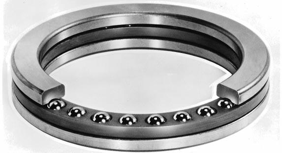
122
123 Thust ball beaings Thust ball beaings ESE Thust ball beaings ae divided into single and double diection types. The fome is able to accommodate axial load in one diection, while the latte is able to accommodate it in both diections. Neithe is suitable fo applications that involve adial load o high-speed otation. Boe diamete mm Bounday dimensions Toleances Standad cages As specified in JIS B As specified in JIS B Pessed steel cage (supplementay code : //) Coppe alloy o cabon steel machined cage (supplementay code : FY o FC) Polyamide esin molded cage (supplementay code : MG) Application of standad cages Beaing seies Molded cage Pessed cage Machined cage Requied minimum axial load Allowable misalignment Equivalent axial load A cetain degee of load is necessay in ode fo beaings to opeate satisfactoily. Misalignment not allowed. (fo flat back face type) Dynamic equivalent axial load P a = F a Static equivalent axial load P 0a = F a B 85
124 Thust ball beaings d mm ød 1 ød ød 1 ød T Bounday dimensions d D T Basic load atings Limiting speeds Dimensions (Refe.) (kn) (min 1 ) Beaing No. Mass Gease C a C d 1 D 1 0a Oil lub. (kg) lub. max Remak) Standad cage types used fo the above beaings ae descibed ealie in this section. B 86
125 d mm Bounday dimensions d D T Basic load atings Limiting speeds Dimensions (Refe.) (kn) (min 1 ) Beaing No. Mass Gease C a C d 1 D 1 0a Oil lub. (kg) lub. max Remak) Standad cage types used fo the above beaings ae descibed ealie in this section. B 87
126 Thust ball beaings d mm ød 1 ød ød 1 ød T Bounday dimensions d D T Basic load atings Limiting speeds Dimensions (Refe.) (kn) (min 1 ) Beaing No. Mass Gease C a C d 1 D 1 0a Oil lub. (kg) lub. max Remak) Standad cage types used fo the above beaings ae descibed ealie in this section. B 88
127 B 89

128
129 Spheical thust olle beaings Spheical thust olle beaings ESE Spheical thust olle beaings ae designed to cay high axial loads. They can also suppot adial load if magnitude is no moe than 55% of the axial load being caied. These beaings ae not suitable fo high-speed otation. Having a spheical housing washe aceway suface, these beaings ae self-alignings, adjusting to axial inclination. They ae usually used with oil lubication. Boe diamete mm Bouday dimensions As specified in JIS B Toleances Requied minimum axial load Standad cage Allowable aligning angle Equivalent axial load As specified in JIS B 1514, class 0. A cetain degee of load is necessay in ode fo beaings to opeate satisfactoily. Coppe alloy machined cage (supplementay code : FY) ad (2 3 ) in geneal, depending on beaing seies. Dynamic equivalent axial load P a = 1.2F + F a Static equivalent axial load P 0a 2.7F + F a (Note : F / F a 0.55) B 91
130 Spheical thust olle beaings d mm ød 1 C B B 1 ød ød 1 ød A T Bounday dimensions d D T Basic load atings (kn) Limiting speeds (min 1 ) C a C 0a Oil lub. Beaing No. Dimensions d 1 D 1 B B 1 C A (Refe.) Mass (kg) R R R R R R 29417R R 29418R R 29420R R 29422R R 29424R R 29426R R 29428R R 29430R R 29432R R 29434R R 29436R B 92
131 d mm Bounday dimensions d D T Basic load atings (kn) Limiting speeds (min 1 ) C a C 0a Oil lub. Beaing No. Dimensions d 1 D 1 B B 1 C A (Refe.) Mass (kg) R 29438R R 29440R R 29444R R 29448R R 29452R R 29456R R 29460R B 93
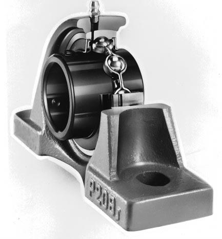
132
133 Ball beaing units ESE Ball beaing units consist of pe-lubicated sealed ball beaings and a housing which vaies in shape. They ae capable of aligning themselves efficiently using the spheical fitting suface between the beaing and housing, effectively peventing oveloads due to misalignment. ESE ball beaing units ae highly accuate and featue excellent load esistance. They ae completely sealed, and povided with a elubication featue. Ball beaing units without a elubication featue ae also available. Pillow block type Boe diamete Flanged type Boe diamete Flanged type with spigot joint mm mm Boe diamete mm Take-up type Boe diamete mm Catidge type Boe diamete mm Light duty units Boe diamete mm "Clean" seies (made fom light alloy) Boe diamete mm Pessed steel housing units Boe diamete mm Ball beaings fo units Boe diamete mm B 95
 Light duty units (cast ion) Pillow block type Rhombic-flanged type")
 Pillow block type Rhombic-flanged type Squae-flanged type UCF 2 X 3 UKF 2")


 UC 2 X 3 SU 0 SB 2 Tapeed boe type")

134 Ball beaing units Majo ball beaing unit types (1) Cast ion units Pillow block type UCP 2 X 3 UKP 2 X 3 (2) Light duty units (cast ion) Pillow block type Rhombic-flanged type BLP 2 BLF 2 Rhombic-flanged type UCFL 2 X 3 UKFL 2 X 3 (3) "Clean" seies units (special light alloy) Pillow block type Rhombic-flanged type Squae-flanged type UCF 2 X 3 UKF 2 X 3 UP 0 UFL 0 (4) Pessed steel housing units Round-flanged type with spigot joint UCFC 2 X UKFC 2 X Squae-flanged type with spigot joint UCFS 3 UKFS 3 SBPP 2 SBPFL 2 SBPF 2 (5) Take-up units with fame Special pillow block type UCPH 2 UCPA 2 Flanged type vaiations Take-up type UCT 2 X 3 UKT 2 X 3 Catidge type UCC 2 UKC 2 Thick section pillow block type UCIP 2 3 UKIP 2 3 Hange type UCTH 2 UCTL 2 UCTU 2 3 (6) Ball beaings fo units Cylindical boe type (set scew locking) UC 2 X 3 SU 0 SB 2 Tapeed boe type (adapte locking) UK 2 X 3 UCFA 2 UCFB 2 UCHA 2 Notes) This catalogue includes the specifications of majo units and beaings which ae boxed in the table. Maks : set scew locking, : adapte locking B 96
135 Toleances Beaing adial intenal cleaance Recommended fits of inne ing and shaft (indicated by the toleance class) Rotation speed limits Allowable aligning angle Ball beaings. as specified in JIS B 1558 (Tables 1 and 2). Housings....as specified in JIS B the intenal spheical diamete toleance is given in Table 3. As specified in JIS B 1520 (Table 2-1 on p. A 11). ESE povides cylindical boe beaings with nomal adial intenal cleaance. Tapeed boe beaings ae povided with a C3 adial intenal cleaance in consideation of possible inne ing expansion caused by tightening of an adapte. Cylindical boe beaings. h6, h7, h8, j6 (k6, k7 and m6 when heavy o impact load is to be suppoted.) Tapeed boe beaings. h8, h9 High-speed blowe beaings (S5). h5, j5 See Table ad (3 ) B 97
136 Ball beaing units Table 1 Ball beaings fo units : inne ing toleance Unit µm Nominal boe diamete d UC, SU and SB types Single plane mean boe diamete deviation d mp ove up to uppe lowe Single adial plane boe diamete vaiation Vd p max. Boe diamete Beaings fo blowe (S5) Single plane mean boe diamete deviation d mp Single adial plane boe diamete vaiation Vd p Single inne (oute) ing width deviation B s ( C s ) Radial unout of assembled beaing inne ing uppe lowe max. uppe lowe max. 10 moe K ia Table 2 Ball beaings fo units : oute ing toleance Unit µm Nominal outside diamete D Mean outside diamete deviation D m Radial unout of assembled beaing oute ing K ea ove up to uppe lowe max. C SøD B ød UC type Note) The lowe value of mean outside diamete deviation does not apply to the sides of oute ings up to the extent of a quate of the oute ing width fom the side faces. Table 3 Housing spheical boe diamete toleance Unit µm Nominal spheical boe diamete D a Toleance class H7 Single plane mean spheical boe diamete deviation D amp ove up to uppe lowe Toleance class J7 Single plane mean spheical boe diamete deviation uppe D amp lowe Toleance class K7 Single plane mean spheical boe diamete deviation uppe D amp lowe All toleance classes Single adial plane spheical boe diamete vaiation Vd p max. SøDa Remak)ESE geneally applies class J to housing designs. Class H and class K and also be applied depending on the application. B 98
137 Table 4 Rotation speed limits of ball beaing units Unit µm Boe diamete No. Standad Diamete seies Tiple lip sealed (L3) Diamete seies Fo high speed otation (K3 and S5) Diamete seies Heat esistant type B (DIK2) Diamete seies 2 X 3 2 X 3 2 X 3 2, X, Remaks) 1. Cold-esistant types (D2K2) and heat-esistant types A (D3K2) featue the same level of otation speed limits as the standad type. 2. Refe to a sepaate catalog fo details of tiple lip sealed beaings, high-speed beaings (K3 and S5) and heatesistant beaings (D1K2 and D3K2). 3. When beaings ae fit loosely, otation speed limits should be compensated fo by the fitting coefficient given below. Fitting coefficient Beaing type Shaft toleance class Standad Tiple lip sealed Fo high speed otation Fo blowe Heat-esistant type B (L3) (K3) (S5) (D1K2) h 5, js 5 h 6 h 7 h 8 h 9 j B 99
138 Ball beaing units pillow block type UCP (set scew locking) d mm S B N 1 ød H 2 N H H 1 A J L Shaft dia. Dimensions d H J L A H 1 H 2 N N 1 B S Bolt size Unit No. Housing No. Applicable beaing (Refe.) Basic load atings Unit No. (kn) Mass (kg) C C M10 UCP201 P203 UC M10 UCP202 P203 UC M10 UCP203 P203 UC M10 UCP204 P204 UC M M M14 UCP205 UCPX05 UCP305 P205 UC PX05 UCX P305 UC M M M14 UCP206 UCPX06 UCP306 P206 UC PX06 UCX P306 UC M M M14 UCP207 UCPX07 UCP307 P207 UC PX07 UCX P307 UC M M M14 UCP208 UCPX08 UCP308 P208 UC PX08 UCX P308 UC M M M16 UCP209 UCPX09 UCP309 P209 UC PX09 UCX P309 UC M M M16 UCP210 UCPX10 UCP310 P210 UC PX10 UCX P310 UC M M M16 UCP211 UCPX11 UCP311 P211 UC PX11 UCX P311 UC Remaks 1) Applicable sizes of gease nipples ae shown below. 1/4-28UNF , X05 X09, PT 1/ , X10 X20, ) Fo beaings with double- o tiple-lip seals, unit and beaing numbe ae suffixed by L2 o L3. (Fo moe detailed infomation, efe to ball beaing fo unit specification tables.) B 100
139 d mm Shaft dia. Dimensions d H J L A H 1 H 2 N N 1 B S Bolt size Unit No. Housing No. Applicable beaing (Refe.) Basic load atings Unit No. (kn) Mass (kg) C C M M M20 UCP212 UCPX12 UCP312 P212 UC PX12 UCX P312 UC M M M20 UCP213 UCPX13 UCP313 P213 UC PX13 UCX P313 UC M M M22 UCP214 UCPX14 UCP314 P214 UC PX14 UCX P314 UC M M M22 UCP215 UCPX15 UCP315 P215 UC PX15 UCX P315 UC M M M22 UCP216 UCPX16 UCP316 P216 UC PX16 UCX P316 UC M M M27 UCP217 UCPX17 UCP317 P217 UC PX17 UCX P317 UC M M M27 UCP218 UCPX18 UCP318 P218 UC PX18 UCX P318 UC M30 UCP319 P319 UC M M30 UCPX20 UCP320 PX20 UCX P320 UC M30 UCP321 P321 UC M33 UCP322 P322 UC M33 UCP324 P324 UC M33 UCP326 P326 UC M33 UCP328 P328 UC Remaks 1) Applicable sizes of gease nipples ae shown below. 1/4-28UNF , X05 X09, PT 1/ , X10 X20, ) Fo beaings with double- o tiple-lip seals, unit and beaing numbe ae suffixed by L2 o L3. (Fo moe detailed infomation, efe to ball beaing fo unit specification tables.) B 101
140 Ball beaing units pillow block type UKP (adapte locking) d mm B 1 N 1 ød H 2 N H H 1 A J L Shaft dia. Dimensions d H J L A H 1 H 2 N N 1 B 1 Bolt size Unit No. Housing No. Applicable beaing Basic load atings No. (kn) C C 0 (Refe.) Unit Mass (kg) M M M M M M M M M M M M M M M M M M M M M M M M M M M20 UKP205 UKPX05 UKP305 UKP206 UKPX06 UKP306 UKP207 UKPX07 UKP307 UKP208 UKPX08 UKP308 UKP209 UKPX09 UKP309 UKP210 UKPX10 UKP310 UKP211 UKPX11 UKP311 UKP212 UKPX12 UKP312 UKP213 UKPX13 UKP313 P205 UK PX05 UKX P305 UK P206 UK PX06 UKX P306 UK P207 UK PX07 UKX P307 UK P208 UK PX08 UKX P308 UK P209 UK PX09 UKX P309 UK P210 UK PX10 UKX P310 UK P211 UK PX11 UKX P311 UK P212 UK PX12 UKX P312 UK P213 UK PX13 UKX P313 UK Remak ) Applicable sizes of gease nipples ae shown below. 1/4-28UNF , X05 X09, PT 1/ , X10 X20, B 102
141 d mm Shaft dia. Dimensions d H J L A H 1 H 2 N N 1 B 1 Bolt size Unit No. Housing No. Applicable beaing Basic load atings No. (kn) C C 0 (Refe.) Unit Mass (kg) M M M M M M M M M M M M27 UKP215 UKPX15 UKP315 UKP216 UKPX16 UKP316 UKP217 UKPX17 UKP317 UKP218 UKPX18 UKP318 P215 UK PX15 UKX P315 UK P216 UK PX16 UKX P316 UK P217 UK PX17 UKX P317 UK P218 UK PX18 UKX P318 UK M30 UKP319 P319 UK M M30 UKPX20 UKP320 PX20 UKX P320 UK M33 UKP322 P322 UK M33 UKP324 P324 UK M33 UKP326 P326 UK M33 UKP328 P328 UK Remak ) Applicable sizes of gease nipples ae shown below. 1/4-28UNF , X05 X09, PT 1/ , X10 X20, B 103
142 Ball beaing units thick section pillow block type UCIP (set scew locking) d mm S B ød H 2 2-øN H H 1 A J L Shaft dia. Dimensions d H J L A H 1 H 2 N B S Bolt size Unit No. Housing No. Applicable beaing Basic load atings No. (kn) C C 0 (Refe.) Unit Mass (kg) M16 UCIP208 IP208 UC M16 UCIP209 IP209 UC M16 UCIP210 IP210 UC M16 UCIP211 IP211 UC M20 UCIP212 IP212 UC M M20 UCIP213 UCIP313 IP213 UC IP313 UC M22 UCIP314 IP314 UC M22 UCIP315 IP315 UC M22 UCIP316 IP316 UC M22 UCIP317 IP317 UC M27 UCIP318 IP318 UC M27 UCIP319 IP319 UC M27 UCIP320 IP320 UC M30 UCIP322 IP322 UC M30 UCIP324 IP324 UC M30 UCIP326 IP326 UC M33 UCIP328 IP328 UC Remaks 1) Applicable sizes of gease nipples ae shown below. 1/4-28UNF PT 1/ , ) Beaings with tiple-lip seals ae indicated by L3 afte the beaing and unit numbe. (Fo moe detailed infomation, efe to ball beaing fo unit specification tables.) B 104
143 B 105
144 Ball beaing units hombic-flanged type UCFL (set scew locking) d mm S A 0 B 2-øN ød L A 1 A 2 A J H Shaft dia. Dimensions d H J L A A 1 A 2 A 0 N B S Bolt size Unit No. Housing No. Applicable beaing (Refe.) Basic load atings Unit No. (kn) Mass (kg) C C M10 UCFL201 FL204 UC M10 UCFL202 FL204 UC M10 UCFL203 FL204 UC M10 UCFL204 FL204 UC M M M16 UCFL205 UCFLX05 UCFL305 FL205 UC FLX05 UCX FL305 UC M M M20 UCFL206 UCFLX06 UCFL306 FL206 UC FLX06 UCX FL306 UC M M M20 UCFL207 UCFLX07 UCFL307 FL207 UC FLX07 UCX FL307 UC M M M20 UCFL208 UCFLX08 UCFL308 FL208 UC FLX08 UCX FL308 UC M M M22 UCFL209 UCFLX09 UCFL309 FL209 UC FLX09 UCX FL309 UC M M M22 UCFL210 UCFLX10 UCFL310 FL210 UC FLX10 UCX FL310 UC M M22 UCFL211 UCFL311 FL211 UC FL311 UC M M27 UCFL212 UCFL312 FL212 UC FL312 UC Remaks 1) Applicable sizes of gease nipples ae shown below. 1/4-28UNF , X05 X09, PT 1/ , X10, ) Fo beaings with double- o tiple-lip seals, unit and beaing numbe ae suffixed by L2 o L3. (Fo moe detailed infomation, efe to ball beaing fo unit specification tables.) B 106
145 d mm Shaft dia. Dimensions d H J L A A 1 A 2 A 0 N B S Bolt size Unit No. Housing No. Applicable beaing (Refe.) Basic load atings Unit No. (kn) Mass (kg) C C M M27 UCFL213 UCFL313 FL213 UC FL313 UC M M30 UCFL214 UCFL314 FL214 UC FL314 UC M M30 UCFL215 UCFL315 FL215 UC FL315 UC M M33 UCFL216 UCFL316 FL216 UC FL316 UC M M33 UCFL217 UCFL317 FL217 UC FL317 UC M M33 UCFL218 UCFL318 FL218 UC FL318 UC Remaks 1) Applicable sizes of gease nipples ae shown below. 1/4-28UNF , X05 X09, PT 1/ , X10, ) Fo beaings with double- o tiple-lip seals, unit and beaing numbe ae suffixed by L2 o L3. (Fo moe detailed infomation, efe to ball beaing fo unit specification tables.) B 107
146 Ball beaing units squae-flanged type UCF (set scew locking) d mm A 0 B S 4-øN L J ød L J A 1 A 2 A Shaft dia. Dimensions d J L A A 1 A 2 A 0 N B S Bolt size Unit No. Housing No. Applicable beaing Basic load atings No. (kn) C C 0 (Refe.) Unit Mass (kg) M10 UCF201 F204 UC M10 UCF202 F204 UC M10 UCF203 F204 UC M10 UCF204 F204 UC M M M M M M M M M M M M M M M M M M M M M20 UCF205 UCFX05 UCF305 UCF206 UCFX06 UCF306 UCF207 UCFX07 UCF307 UCF208 UCFX08 UCF308 UCF209 UCFX09 UCF309 UCF210 UCFX10 UCF310 UCF211 UCFX11 UCF311 F205 UC FX05 UCX F305 UC F206 UC FX06 UCX F306 UC F207 UC FX07 UCX F307 UC F208 UC FX08 UCX F308 UC F209 UC FX09 UCX F309 UC F210 UC FX10 UCX F310 UC F211 UC FX11 UCX F311 UC Remaks 1) Applicable sizes of gease nipples ae shown below. 1/4-28UNF , X05 X09, PT 1/ , X10 X20, ) Fo beaings with double- o tiple-lip seals, unit and beaing numbe ae suffixed by L2 o L3. (Fo moe detailed infomation, efe to ball beaing fo unit specification tables.) B 108
147 d mm Shaft dia. Dimensions d J L A A 1 A 2 A 0 N B S Bolt size Unit No. Housing No. Applicable beaing Basic load atings No. (kn) C C 0 (Refe.) Unit Mass (kg) M M M M M M M M M M M M M M M M M M M M M30 UCF212 UCFX12 UCF312 UCF213 UCFX13 UCF313 UCF214 UCFX14 UCF314 UCF215 UCFX15 UCF315 UCF216 UCFX16 UCF316 UCF217 UCFX17 UCF317 UCF218 UCFX18 UCF318 F212 UC FX12 UCX F312 UC F213 UC FX13 UCX F313 UC F214 UC FX14 UCX F314 UC F215 UC FX15 UCX F315 UC F216 UC FX16 UCX F316 UC F217 UC FX17 UCX F317 UC F218 UC FX18 UCX F318 UC M30 UCF319 F319 UC M M33 UCFX20 UCF320 FX20 UCX F320 UC M33 UCF321 F321 UC M36 UCF322 F322 UC M36 UCF324 F324 UC M36 UCF326 F326 UC M36 UCF328 F328 UC Remaks 1) Applicable sizes of gease nipples ae shown below. 1/4-28UNF , X05 X09, PT 1/ , X10 X20, ) Fo beaings with double- o tiple-lip seals, unit and beaing numbe ae suffixed by L2 o L3. (Fo moe detailed infomation, efe to ball beaing fo unit specification tables.) B 109
148 Ball beaing units ound-falnged type with spigot joint UCFC (set scew locking) B d mm S A 2 4-øN øh 3 ød øl øj A 3 A 1 A A 0 J 1 Shaft dia. Dimensions d L J J 1 H 3 A A 1 A 2 A 3 A 0 N B S Bolt size Unit No. Housing No. Applicable beaing (Refe.) Basic load atings Unit No. (kn) Mass (kg) C C M10 UCFC201 FC204 UC M10 UCFC202 FC204 UC M10 UCFC203 FC204 UC M10 UCFC204 FC204 UC M M8 UCFC205 UCFCX05 FC205 UC FCX05 UCX M M10 UCFC206 UCFCX06 FC206 UC FCX06 UCX M M10 UCFC207 UCFCX07 FC207 UC FCX07 UCX M M10 UCFC208 UCFCX08 FC208 UC FCX08 UCX M M12 UCFC209 UCFCX09 FC209 UC FCX09 UCX M M12 UCFC210 UCFCX10 FC210 UC FCX10 UCX M M14 UCFC211 UCFCX11 FC211 UC FCX11 UCX M M14 UCFC212 UCFCX12 FC212 UC FCX12 UCX M M14 UCFC213 UCFCX13 FC213 UC FCX13 UCX M M16 UCFC214 UCFCX14 FC214 UC FCX14 UCX Remaks 1) Applicable sizes of gease nipples ae shown below. 1/4-28UNF , X05 X09 PT 1/ , X10 X20 2) Fo beaings with double- o tiple-lip seals, unit and beaing numbe ae suffixed by L2 o L3. (Fo moe detailed infomation, efe to ball beaing fo unit specification tables.) B 110
149 d mm Shaft dia. Dimensions d L J J 1 H 3 A A 1 A 2 A 3 A 0 N B S Bolt size Unit No. Housing No. Applicable beaing (Refe.) Basic load atings Unit No. (kn) Mass (kg) C C M M16 UCFC215 UCFCX15 FC215 UC FCX15 UCX M M20 UCFC216 UCFCX16 FC216 UC FCX16 UCX M M20 UCFC217 UCFCX17 FC217 UC FCX17 UCX M M20 UCFC218 UCFCX18 FC218 UC FCX18 UCX M20 UCFCX20 FCX20 UCX Remaks 1) Applicable sizes of gease nipples ae shown below. 1/4-28UNF , X05 X09 PT 1/ , X10 X20 2) Fo beaings with double- o tiple-lip seals, unit and beaing numbe ae suffixed by L2 o L3. (Fo moe detailed infomation, efe to ball beaing fo unit specification tables.) B 111
150 Ball beaing units squae-flanged type with spigot joint UCFS (set scew locking) d mm B S A 2 4-øN L J øh 3 ød L J A 3 A 1 A A 0 Shaft dia. Dimensions d J L H 3 A A 1 A 2 A 3 A 0 N B S Bolt size Unit No. Housing No. Applicable beaing Basic load atings No. (kn) C C 0 (Refe.) Unit Mass (kg) M14 UCFS305 FS305 UC M14 UCFS306 FS306 UC M16 UCFS307 FS307 UC M16 UCFS308 FS308 UC M16 UCFS309 FS309 UC M20 UCFS310 FS310 UC M20 UCFS311 FS311 UC M20 UCFS312 FS312 UC M20 UCFS313 FS313 UC M22 UCFS314 FS314 UC M22 UCFS315 FS315 UC M27 UCFS316 FS316 UC M27 UCFS317 FS317 UC M30 UCFS318 FS318 UC M30 UCFS319 FS319 UC M33 UCFS320 FS320 UC M33 UCFS321 FS321 UC M36 UCFS322 FS322 UC M36 UCFS324 FS324 UC M36 UCFS326 FS326 UC M36 UCFS328 FS328 UC Remaks 1) Applicable sizes of gease nipples ae shown below. 1/4-28UNF PT 1/ ) Beaings with tiple-lip seals ae indicated by L3 afte the beaing and unit numbe. (Fo moe detailed infomation, efe to ball beaing fo unit specification tables.) B 112
151 B 113
152 Ball beaing units take-up type UCT (set scew locking) d mm B S L 1 H 1 ød H 2 øn H N 2 A 1 A 2 A L 2 N 1 L L 3 Shaft dia. Dimensions d A A 1 A 2 H H 1 H 2 L L 1 L 2 L 3 N N 1 N 2 B S Unit No. Housing No. Applicable beaing (Refe.) Basic load atings Unit No. (kn) Mass (kg) C C UCT201 T204 UC UCT202 T204 UC UCT203 T204 UC UCT204 T204 UC UCT205 UCTX05 UCT305 UCT206 UCTX06 UCT306 T205 UC TX05 UCX T305 UC T206 UC TX06 UCX T306 UC UCT207 UCTX07 UCT307 UCT208 UCTX08 UCT308 UCT209 UCTX09 UCT309 T207 UC TX07 UCX T307 UC T208 UC TX08 UCX T308 UC T209 UC TX09 UCX T309 UC UCT210 UCTX10 UCT310 UCT211 UCTX11 UCT311 T210 UC TX10 UCX T310 UC T211 UC TX11 UCX T311 UC Remaks 1) Applicable sizes of gease nipples ae shown below. 1/4-28UNF , X05 X09, PT 1/ , X10 X17, ) Fo beaings with double- o tiple-lip seals, unit and beaing numbe ae suffixed by L2 o L3. (Fo moe detailed infomation, efe to ball beaing fo unit specification tables.) B 114
153 d mm Shaft dia. Dimensions d A A 1 A 2 H H 1 H 2 L L 1 L 2 L 3 N N 1 N 2 B S Unit No. Housing No. Applicable beaing (Refe.) Basic load atings Unit No. (kn) Mass (kg) C C UCT212 UCTX12 UCT312 UCT213 UCTX13 UCT313 UCT214 UCTX14 UCT314 UCT215 UCTX15 UCT315 UCT216 UCTX16 UCT316 UCT217 UCTX17 UCT317 T212 UC TX12 UCX T312 UC T213 UC TX13 UCX T313 UC T214 UC TX14 UCX T314 UC T215 UC TX15 UCX T315 UC T216 UC TX16 UCX T316 UC T217 UC TX17 UCX T317 UC UCT318 T318 UC UCT319 T319 UC UCT320 T320 UC UCT321 T321 UC UCT322 T322 UC UCT324 T324 UC UCT326 T326 UC UCT328 T328 UC Remaks 1) Applicable sizes of gease nipples ae shown below. 1/4-28UNF , X05 X09, PT 1/ , X10 X17, ) Fo beaings with double- o tiple-lip seals, unit and beaing numbe ae suffixed by L2 o L3. (Fo moe detailed infomation, efe to ball beaing fo unit specification tables.) B 115
154 Ball beaing units catidge type UCC (set scew locking) d mm S B ød øh A Shaft dia. Dimensions d H A B S Unit No. Housing No. No. Applicable beaing Basic load atings (kn) C C 0 (Refe.) Unit Mass (kg) UCC201 C204 UC UCC202 C204 UC UCC203 C204 UC UCC204 C204 UC UCC205 C205 UC UCC206 C206 UC UCC207 C207 UC UCC208 C208 UC UCC209 C209 UC UCC210 C210 UC UCC211 C211 UC UCC212 C212 UC UCC213 C213 UC Remaks 1) Applicable sizes of gease nipples ae shown below. (1/4-28UNF ) 2) Fo beaings with double- o tiple-lip seals, unit and beaing numbe ae suffixed by L2 o L3. (Fo moe detailed infomation, efe to ball beaing fo unit specification tables.) B 116
155 Ball beaing units light duty pillow block type BLP (set scew locking) d mm N 1 S B ød H 2 N H H 1 A J L Shaft dia. Dimensions d H J L A H 1 H 2 N N 1 B S Bolt size Unit No. Housing No. Applicable beaing Basic load atings No. (kn) C C 0 (Refe.) Unit Mass (kg) M10 BLP201 LP203 SB M10 BLP202 LP203 SB M10 BLP203 LP203 SB M10 BLP204 LP204 SB M10 BLP205 LP205 SB M12 BLP206 LP206 SB M12 BLP207 LP207 SB M12 BLP208 LP208 SB B 117
156 Ball beaing units light duty hombic-flanged type BLF (set scew locking) d mm A 2 A 0 2-øN S B ød L A 1 A J H Shaft dia. Dimensions d H J L A A 1 A 2 A 0 N B S Bolt size Unit No. Housing No. Applicable beaing Basic load atings No. (kn) C C 0 (Refe.) Unit Mass (kg) M6 BLF201 LF203 SB M6 BLF202 LF203 SB M6 BLF203 LF203 SB M8 BLF204 LF204 SB M8 BLF205 LF205 SB M10 BLF206 LF206 SB M10 BLF207 LF207 SB B 118
157 Ball beaing units "clean" seies pillow block type UP (set scew locking) d mm S B ød H 2 H 2-øN H 1 A J L Shaft dia. Dimensions d H J L A H 1 H 2 N B S Bolt size Unit No. Housing No. Applicable beaing Basic load atings No. (kn) C C 0 (Refe.) Unit Mass (kg) M6 UP000 P000 SU M6 UP001 P001 SU M6 UP002 P002 SU M6 UP003 P003 SU M8 UP004 P004 SU M8 UP005 P005 SU M10 UP006 P006 SU B 119
158 Ball beaing units "clean" seies hombic-flanged type UFL (set scew locking) d mm A 2 A 0 2-øN S B ød L A 1 A J H Shaft dia. Dimensions d H J L A A 1 A 2 A 0 N B S Bolt size Unit No. Housing No. Applicable beaing Basic load atings No. (kn) C C 0 (Refe.) Unit Mass (kg) M6 UFL000 FL000 SU M6 UFL001 FL001 SU M6 UFL002 FL002 SU M6 UFL003 FL003 SU M8 UFL004 FL004 SU M8 UFL005 FL005 SU M10 UFL006 FL006 SU B 120
159 Ball beaing units pessed steel pillow block type SBPP (set scew locking) d mm S B ød H 2 2-øN H H 1 A J L Shaft dia. Dimensions d H J L A H 1 H 2 N B S Bolt size Unit No. Housing No. Applicable beaing Basic load atings No. (kn) C C 0 (Refe.) Unit Mass (kg) M8 SBPP201F PP203F SB M8 SBPP202F PP203F SB M8 SBPP203F PP203F SB M8 SBPP204F PP204F SB M10 SBPP205F PP205F SB M10 SBPP206F PP206F SB M10 SBPP207F PP207F SB B 121
160 Ball beaing units pessed steel hombic-flanged type SBPFL (set scew locking) d mm A N øh 2 S B ød N L A 1 J H Shaft dia. Dimensions d H J L A A 1 N H 2 1) B S Bolt size Unit No. Housing No. Applicable beaing Basic load atings No. (kn) C C 0 (Refe.) Unit Mass (kg) M6 SBPFL201 PFL203 SB M6 SBPFL202 PFL203 SB M6 SBPFL203 PFL203 SB M8 SBPFL204 PFL204 SB M8 SBPFL205 PFL205 SB M10 SBPFL206 PFL206 SB M10 SBPFL207 PFL207 SB Note 1) H 2 shows minimum dimension of mounting hole. B 122
161 Ball beaing units pessed steel ound-flanged type SBPF (set scew locking) d mm A N N øh 2 S B ød øh øj A 1 Shaft dia. Dimensions d H J A A 1 N H 2 1) B S Bolt size Unit No. Housing No. Applicable beaing Basic load atings No. (kn) C C 0 (Refe.) Unit Mass (kg) M6 SBPF201 PF203 SB M6 SBPF202 PF203 SB M6 SBPF203 PF203 SB M8 SBPF204 PF204 SB M8 SBPF205 PF205 SB M10 SBPF206 PF206 SB M10 SBPF207 PF207 SB Note 1) H 2 shows minimum dimension of mounting hole. B 123
162 Ball beaings fo units cylindical boe type (set scew locking) d mm B C S 2 B B C C G S G S G SøD S S 1 ød SøD S S 1 ød SøD S S 1 ød UC UC...L3 (with tiple-lip seals) SU SB Shaft dia. d Bounday dimensions D B C Basic load atings (kn) C C 0 With standad seals Beaing No. With tiple-lip seals S Dimensions S 1 S 2 Set scew size G (Refe.) Mass (kg) SU M SU001 SB201 UC201 UC201L M M M SU002 SB202 UC202 UC202L M M M SU003 SB203 UC203 UC203L M M M SU004 SB204 UC204 UC204L M M M SU005 SB205 UC205 UC205L M M M UC305 UCX05 UCX05L M M SU006 SB206 UC206 UC206L M M M UCX06 UCX06L3 UC M M SB207 UC207 UC207L3 UC307 UC307L M M M UCX07 UCX07L M SB208 UC208 UC208L3 UCX08 UCX08L M M M UC308 UC308L M Remak) Beaing in numbe ange fom UC201L2 to UC205L2 ae double-lip sealed (L2) due to dimensional estiction. B 124
163 d mm Shaft dia. d Bounday dimensions D B C Basic load atings (kn) C C 0 With standad seals Beaing No. With tiple-lip seals S Dimensions S 1 S 2 Set scew size G (Refe.) Mass (kg) UC209 UCX09 UC309 UC209L3 UCX09L3 UC309L M M M UC210 UCX10 UC310 UC210L3 UCX10L3 UC310L M M M UC211 UCX11 UC311 UC211L3 UCX11L3 UC311L M M M UC212 UCX12 UC312 UC212L3 UCX12L3 UC312L M M M UC213 UCX13 UC313 UC213L3 UCX13L3 UC313L M M M UC214 UCX14 UC314 UC214L3 UCX14L3 UC314L M M M UC215 UCX15 UC315 UC215L3 UCX15L3 UC315L M M M UC216 UCX16 UC316 UC216L3 UCX16L3 UC316L M M M UC217 UCX17 UC317 UC217L3 UCX17L3 UC317L M M M UC218 UC218L3 UCX18 UC318 UC318L M M M UC319 UC319L M UCX20 UC320 UC320L M M UC M UC322 UC322L M UC324 UC324L M UC326 UC326L M UC328 UC328L M B 125
164 Ball beaings fo units tapeed boe type (adapte locking) d mm C B 2 B B 1 SøD ød ød 1 ød 2 UK Adapte assembly Shaft dia. d 1 Bounday dimensions Basic load atings (Refe.) Applicable adapte assembly (kn) Beaing Mass Dimensions Mass No. d D B C C C 0 (kg) No. B 1 B 2 d 2 (kg) Sleeve No UK205 UKX05 UK H305X A305X 0.27 H2305X A2305X 0.40 H2305X A2305X UK206 UKX06 UK H306X A306X 0.43 H2306X A2306X 0.47 H2306X A2306X UK207 UKX07 UK H307X A307X 0.53 H2307X A2307X 0.60 H2307X A2307X UK208 UKX08 UK H308X A308X 0.58 H2308X A2308X 0.80 H2308X A2308X UK209 UKX09 UK H309X A309X 0.67 H2309X A2309X 1.08 H2309X A2309X UK210 UKX10 UK H310X A310X 0.89 H2310X A2310X 1.38 H2310X A2310X UK211 UKX11 UK H311X A311X 1.15 H2311X A2311X 1.78 H2311X A2311X UK212 UKX12 UK H312X A312X 1.45 H2312X A2312X 2.06 H2312X A2312X UK213 UKX13 UK H313X A313X 1.62 H2313X A2313X 2.71 H2313X A2313X UK215 UKX15 UK H315X A315X 2.10 H2315X A2315X 3.80 H2315X A2315X B 126
165 d mm Shaft dia. d 1 Bounday dimensions Basic load atings (Refe.) Applicable adapte assembly (kn) Beaing Mass Dimensions Mass No. d D B C C C 0 (kg) No. B 1 B 2 d 2 (kg) Sleeve No UK216 UKX16 UK H316X A316X 2.64 H2316X A2316X 4.39 H2316X A2316X UK217 UKX17 UK H317X A317X 3.25 H2317X A2317X 5.30 H2317X A2317X UK218 UKX18 UK H318X A318X 3.80 H2318X A2318X 6.20 H2318X A2318X UK H2319X A2319X UKX20 UK H2320X A2320X 8.70 H2320X A2320X UK H2322X A2322X UK H A UK H A UK H A2328 B 127
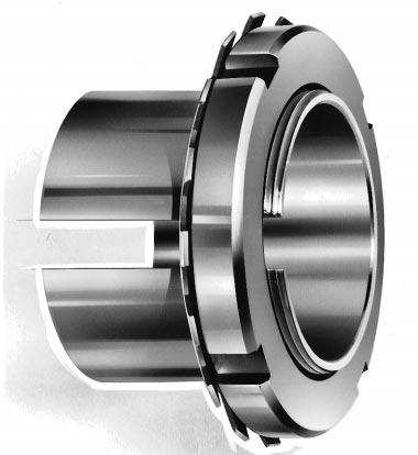
166
167 Locknuts and lockwashes Beaings ae often fit to a shaft with an adapte sleeve, locknut, lockwashe o lock plate. These accessoies make it easy to attach and emove beaings. They ae standadized in JIS. Locknuts ae standadized such that they can be used with eithe adapte sleeves, withdawal sleeves o shafts. Lockwashes and lock plates ae used as locks on locknuts. Lockwashes ae used with beaings of boe diamete numbe 40 o lowe. Lock plates ae used with those of boe diamete 44 o highe. Locknuts AN Lockwashes AW (X) B 129
168 Locknuts fo adapte sleeves and shafts AN02 25 B g 30 b h G 1 d 2 ød 1 ød 3 Locknut No. Thead size G 1) Standad dimensions d 2 d 1 g d 3 b h B max. (Refe.) Mass (kg) Applicable 2) adapte sleeve (boe No.) Applicable 3) lockwashe No. AN AN AN AN AN AN AN AN M AW02 M M M AW05 M M M AW08 M M M AW11 M M M AW14 M M M AW17 M M M AW20 M M M AW23 M M Notes 1) Basic pofile and dimension of scew thead ae in accodance with JIS B 0207 (metic fine scew theads). 2) Applicable to adapte sleeve seies A31, A2, A3 and A23. 3) Applicable to lockwashes with flat inne tongue. B 130
169 AN26 40 Locknut No. Thead size G 1) Standad dimensions d 2 d 1 g d 3 b h B max. (Refe.) Mass (kg) Applicable 2) adapte sleeve (boe No.) Applicable 3) lockwashe No. AN AN AN AN M AW26 M M M AW29 M M M AW32 M M M AW36 M M B 131
170 Locknuts fo adapte sleeves and shafts AN B l S g b h G 1 d 2 ød 1 ød 3 ød p Locknut No. Thead size G 1) Standad dimensions d 2 d 1 g d 3 b h B max. l Tapped hole (Refe.) Mass S 2) Thead size d p (kg) Applicable 3) adapte sleeve (boe No.) Applicable lock plate No. AN AN AN AN T M AL44 T M T M T M AL52 T M T M T M AL68 T M T M T M AL80 T M T M AN T M AL88 T M T M / Notes 1) Basic pofile and dimension of scew thead ae in accodance with JIS B ) Basic pofile and dimension of boe with intenal thead ae in accodance with JIS B 0205 (metic coase scew theads). 3) Applicable to adapte sleeve seies A31, A32, A23 and A30. B 132
171 Lockwashes AW00 40(X) 25 f 2 B 2 f 1 ød 4 ød 5 B 1 d 3 M With bent inne tongue With flat inne tongue Lockwashe No. With bent inne tongue With flat inne tongue Standad dimensions No. of tooth (Refe.) Mass d 3 M f 1 B 1 f d 4 d 5 B 2 (kg/100pcs.) Applicable adapte sleeve (boe No.) Applicable locknut No. AW00 AW00X 01 01X 02 02X AW03 AW03X 04 04X 05 05X AW06 AW06X 07 07X 08 08X AW09 AW09X 10 10X 11 11X AW12 AW12X 13 13X 14 14X AW15 AW15X 16 16X 17 17X AW18 AW18X 19 19X 20 20X AW21 AW21X 22 22X 23 23X AW24 AW24X 25 25X 26 26X AW27 AW27X 28 28X 29 29X AW30 AW30X 31 31X 32 32X AW33 AW33X 34 34X 36 36X AW38 AW38X 40 40X AN AN AN AN AN AN AN AN AN AN AN AN AN Remaks 1) AW00 AW40, AW00X AW40X ae applicable to adapte assembly seies H31, H2, H3 and H23. 2) Fo adapte sleeves with naow slits, lockwashes with flat inne tongue should be used. Eithe type of lockwashe can be used fo adapte sleeves with wide slits. B 133
172 Supplementay tables Contents 1. Shaft toleances (deviation fom nominal dimensions)... C 2 2. Housing boe toleances (deviation fom nominal dimensions)... C 4 3. Numeical values fo standad toleance gades IT... C 6 4. Geek alphabet list... C 7 5. Pefixes used with SI units... C 7 6. SI units and convesion factos... C 8 7. Inch/millimete convesion... C12 8. Steel hadness convesion... C13 9. Suface oughness compaison... C Viscosity convesion... C15 C 1
173 Supplementay tables Supplementay table 1 Shaft toleances (deviation fom nominal dimensions) Nominal shaft diamete Deviation classes of shaft diamete ove up to d6 e6 f6 g5 g6 h5 h6 h7 h8 h9 h10 js5 js6 js7 j5 j ± 2.5 ± 4 ± ± 3 ± 4.5 ± ± 4 ± 5.5 ± ± 4.5 ± 6.5 ± ± 5.5 ± 8 ± ± 6.5 ± 9.5 ± ± 7.5 ±11 ± ± 9 ±12.5 ± ±10 ±14.5 ± ±11.5 ±16 ±26 ± ±12.5 ±18 ±28 ± ±13.5 ±20 ±31 ± ±22 ± ±25 ± ±28 ± Note 1) dmp : single plane mean boe diamete deviation C 2
174 k5 k6 k7 m5 m6 m7 n5 n6 p Unit µm (Refe.) Nominal shaft diamete ove up to dmp 1) of beaing (class 0) C 3
175 Supplementay tables Supplementay table 2 Housing boe toleances (deviation fom nominal dimensions) Nominal boe diamete Deviation classes of housing boe diamete ove up to E6 F6 F7 G6 G7 H6 H7 H8 H9 H10 J6 J7 JS5 JS6 JS ± 4 ± 5.5 ± ± 4.5 ± 6.5 ± ± 5.5 ± 8 ± ± 6.5 ± 9.5 ± ± 7.5 ±11 ± ± 9 ±12.5 ± ± ±14.5 ± ± ±16 ± ±12.5 ±18 ± ±13.5 ±20 ± ±22 ± ±25 ± ±28 ± ±33 ±52 Note 1) D mp : single plane mean outside diamete deviation C 4
176 K5 K6 K7 M5 M6 M7 N5 N6 N7 P6 P7 R Unit µm (Refe.) Nominal boe diamete ove up to Dmp 1) of beaing (class 0) (up to150 ) 0 18 (ove 150) C 5
177 Supplementay tables Supplementay table 3 Numeical values fo standad toleance gades IT Basic size Standad toleance gades (IT) ) 15 1) 16 1) 17 1) 18 1) ove up to Toleances (µm) Toleances Note 1) Standad toleance gades IT 14 to IT 18 (incl.) shall not be used fo basic sizes less than o equal to 1 mm. C 6
178 Supplementay table 4 Geek alphabet list Name Roman type Italic type Name Roman type Italic type Capital Capital Lowecase Capital Capital Lowecase alpha beta gamma delta epsilon zeta eta theta iota kappa lambda mu Α Β Γ Ε Ζ Η Θ Ι Κ Λ Μ Α Β Γ Ε Ζ Η Θ Ι Κ Λ Μ α β γ δ ζ η ι χ, κ λ µ nu xi omicon pi ho sigma tau upsilon phi chi psi omega Ν Ξ Ο Π Ρ Σ Τ ϒ Φ Χ Ψ Ω Ν Ξ Ο Π Ρ Σ Τ ϒ Φ Χ Ψ Ω ν ξ ο π ρ σ τ υ χ ψ ω Supplementay table 5 Pefixes used with SI units Facto Name Pefix Symbol Facto Name Pefix Symbol exa peta tea giga mega kilo hecto deka E P T G M k h da deci centi milli mico nano pico femto atto d c m n p f a C 7
179 Supplementay tables Supplementay table 6 (1) SI units and convesion factos Mass SI units Othe Units 1) Convesion into SI units Convesion fom SI units Angle ad [degee(s)] 1 = π / 180 ad 1 ad = [adian(s)] ' [minute(s)] 1' = π / ad " [second(s)] 1" = π / ad Length m Å [Angstom unit] 1Å = m = 0.1 nm = 100 pm 1 m = Å [mete(s)] µ [micon(s)] 1µ = 1µm in [inch(es)] 1 in = 25.4 mm 1 m = in ft [foot(feet)] 1 ft = 12 in = m 1 m = ft yd [yad(s)] 1 yd = 3 ft = m 1 m = yd mile [mile(s)] 1 mile = ft = m 1 km = mile Aea m 2 a [ae(s)] 1 a = 100 m 2 ha [hectae(s)] 1 ha = 10 4 m 2 ace [ace(s)] 1 ace = yd 2 = m 2 1 km 2 = ace Volume m 3, L [lite(s)] 1 = 1 dm 3 = 10 3 m 3 1 m 3 = 10 3 cc [cubic centimetes] 1 cc = 1 cm 3 = 10 6 m 3 1 m 3 = 10 6 cc gal (US) [gallon(s)] 1 gal (US) = 231 in 3 = dm 3 1 m 3 = gal floz (US) [fluid ounce(s)] 1 floz (US) = cm 3 1 m 3 = floz bael (US) [baels(us)] 1 bael (US) = dm 3 1 m 3 = bael Time s min [minute(s)] [second(s)] h [hou(s)] d [day(s)] Angula velocity ad/s Velocity m/s kn [knot(s)] 1 kn = m/h 1 km/h = kn m/h Acceleation m/s 2 G 1 G = m/s 2 1 m/s 2 = G Fequency Hz c/s [cycle(s)/second] 1 c/s = 1 s 1 = 1 Hz [hetz] Rotational s 1 pm [evolutions pe minute] 1 pm = 1/60 s 1 1 s 1 = 60 pm fequency min 1 /min Mass kg t [ton(s)] 1 t = 10 3 kg [kilogam(s)] lb [pound(s)] 1 lb = kg 1 kg = lb g [gain(s)] 1 g = mg 1 g = g oz [ounce(s)] 1 oz = 1/16 lb = g 1 kg = oz ton (UK) [ton(s) (UK)] 1 ton (UK) = kg 1 t = ton (UK) ton (US) [ton(s) (US)] 1 ton (US) = kg 1 t = ton (US) ca [caat(s)] 1 ca = 200 mg 1 g = 5 ca Note 1) : Unit can be used as an SI unit. : Unit can be used as an SI unit fo the time being. No asteisk : Unit cannot be used. C 8
180 Supplementay table 6 (2) SI units and convesion factos Mass SI units Othe Units 1) Convesion into SI units Convesion fom SI units Density kg/m 3 Linea density Momentum kg/m kg m/s Moment of momentum Angula momentum kg m 2 /s Moment of kg m 2 inetia Foce N dyn [dyne(s)] 1 dyn = 10 5 N 1 N = 10 5 dyn [newton(s)] kgf [kilogam-foce] 1 kgf = N 1 N = kgf gf [gam-foce] 1 gf = N tf [ton-foce] 1 tf = N lbf [pound-foce] 1 lbf = N 1 N = lbf Moment of N m gf cm 1 gf cm = N m foce [newton kgf cm 1 kgf cm = N m mete(s)] kgf m 1 kgf m = N m 1 N m = kgf m tf m 1 tf m = N m tf lbf 1 ft lbf = N m 1 N m = ft lbf Pessue Pa gf/ cm 2 1 gf/ cm 2 = Pa [pascal(s)] kgf/mm 2 1 kgf/mm 2 = Pa 1 MPa = kgf/mm 2 kgf/m 2 1 kgf/m 2 = Pa 1 Pa = kgf/m 2 Nomal stess lbf/in 2 1 lbf/in 2 = Pa 1 Pa = lbf/in 2 {1 Pa = 1 N/m 2 } ba [ba(s)] 1 ba = 10 5 Pa 1 Pa = 10 2 mba at [engineeing ai pessue] 1 at = 1kgf/cm 2 = Pa mh2o, maq [mete wate column] 1 mh2o = Pa atm [atmosphee] 1 atm = Pa mhg [mete mecuy 1 mhg = column] 0.76 Pa To [to] 1 To = 1mmHg = Pa 1 Pa = To Viscosity Pa s P [poise] 10 2 P = 1 cp = 1 mpa s [pascal second] kgf s/m 2 1 kgf s/m 2 = Pa s 1 Pa s = kgf s/m 2 Kinematic m 2 /s St [stokes] 10 2 St = 1 cst = 1 mm 2 /s viscosity Suface tension N/m Note 1) : Unit can be used as an SI unit. : Unit can be used as an SI unit fo the time being. No asteisk : Unit cannot be used. C 9
181 Supplementay tables Supplementay table 6 (3) SI units and convesion factos Mass SI units Othe Units 1) Convesion into SI units Convesion fom SI units Wok J ev [electon volt(s)] 1 ev = ( ± ) J [ joule(s)] eg [eg(s)] 1 eg = 10 7 J 1 J = 10 7 eg W s kgf m 1 kgf m = J 1 J = kgf m Enegy [watt(s) second] ft lbf 1 ft lbf = J 1 J = ft lbf 1 J = 1 N m 1 W s = 1 J Powe W eg/s [egs pe second] 1 eg/s = 10 7 W [watt(s)] kgf m/s 1 kgf m/s = W 1 W = kgf m/s {1 W = 1 J/s} PS [Fench hose-powe] 1 PS = 75 kgf m/s = W 1 W = PS HP [hose-powe (Bitish)] 1 HP = 550 ft lbf/s = W 1 W = HP ft lbf/s 1 ft lbf/s = W Themo-dynamic K 1 tempeatue [kelvin(s)] {t K= (t ) C} Celsius C F [degee(s) Fahenheit] tempeatue [celsius(s)] {t C = (t ) K} t F = 5 9 (t 32) C t C = ( 9 5 t+32) F Linea expansion K 1 C 1 [pe degee] coefficient Heat J eg [eg(s)] 1 eg = 10 7 J 1 J = 10 7 eg [joule(s)] kgf m cal [caloies] 1 cal = J 1 J = cal (when tempeatue is not specified) cal 15 [15 degee caloies] 1 cal15 = J cal IT [I. T. caloies] 1 calit = J 1 McalIT = kw h 1 kw h = cal Themal W/ (m K) W/ (m C) 1 W/ (m C) = 1 W/ (m K) conductivity cal/ (s m C) 1 cal/ (s m C) = W/ (m K) Coeffcient of W/ (m 2 K) W/ (m 2 C) 1 W/ (m 2 C) = 1 W/ (m 2 K) heat tansfe cal/ (s m 2 C) 1 cal/ (s m 2 C) = W/ (m 2 K) Heat capacity J/K J/ C 1 J/ C = 1 J/K Massic heat J/ (kg K) J/ (kg C) capacity Note 1) : Unit can be used as an SI unit. : Unit can be used as an SI unit fo the time being. No asteisk : Unit cannot be used. C 10
182 Supplementay table 6 (4) SI units and convesion factos Mass SI units Othe Units 1) Convesion into SI units Convesion fom SI units Electic cuent A [ampee(s)] Electic chage C A h 1 A h = 3.6 kc [coulomb(s)] Quantity of {1 C = 1 A s} electicity Tension V [volt(s)] Electic potential {1 V = 1 W/A} Capacitance F [faad(s)] {1 F = 1 C/V} Magnetic field A/m Oe [oested(s)] stength Oe = A/m 4π 1 A/m = 4π 10 3 Oe Magnetic flux T Gs [gauss(es)] 1 Gs = 10 4 T 1 T = 10 4 Gs density [tesla(s)] γ [ gamma(s)] 1 γ = 10 9 T 1 T = 10 9 γ 1 T = 1 N/(A m) = 1 Wb/m 2 = 1 V s/m 2 Magnetic flux Wb Mx [maxwell(s)] 1 Mx =10 8 Wb 1 Wb = 10 8 Mx [webe(s)] {1 Wb = 1 V s} Self inductance Resistance (to diect cuent) H [heny ( ies)] {1 H = 1 Wb/A} Ω [ohm(s)] {1 Ω = 1 V/A} Conductance (to diect cuent) S [siemens] {1 S = 1 A/V} Active powe Note 1) W 1 W = 1 J/s = 1 A V : Unit can be used as an SI unit. : Unit can be used as an SI unit fo the time being. No asteisk : Unit cannot be used. C 11
183 Supplementay tables Supplementay table 7 Inch/millimete convesion Inch Inches mm / / / / / / / / / / / / / / / / / / / / / / / / / / / / / / / / / / / / / / / / / / / / / / / / / / / / / / / / / / / / / / / C 12
184 Supplementaty table 8 Steel hadness convesion Rockwell Binell Rockwell C-scale N {150 kgf} Vicke's Standad ball Tungsten cabide ball A-scale N {60 kgf} B-scale N {100 kgf} Shoe (109.0) (108.5) (108.0) (107.5) (107.0) (106.0) (105.5) (104.5) (104.0) (103.0) (102.5) (101.5) (101.0) (18) (16) (14) (12) (10) ( 8) ( 6) ( 4) ( 2) ( 0) C 13
185 Supplementay tables Supplementay table 9 Suface oughness compaison Aithmetical mean deviation of the pofile R a Maximum height of the pofile R max Ten-point height of iegulaities R z Roughness gade numbes N a a 0.05 a 0.10 a 0.20 a 0.40 a 0.80 a 1.6 a 3.2 a 6.3 a 12.5 a 25. a 50. a 100. a 0.05 S 0.1 S 0.2 S 0.4 S 0.8 S 1.6 S 3.2 S 6.3 S 12.5 S 25. S 50. S 100. S 200. S 400. S 0.05 Z 0.1 Z 0.2 Z 0.4 Z 0.8 Z 1.6 Z 3.2 Z 6.3 Z 12.5 Z 25. Z 50. Z 100. Z 200. Z 400. Z N 1 N 2 N 3 N 4 N 5 N 6 N 7 N 8 N 9 N10 N11 N12 Notes) Above table is applicable only when pocessed suface peaks ae of equal height. Above table is oughly applicable to pocessed sufaces fo geneal use. Numbes ae combined only fo convenience in deciding suface oughness. Symbol C 14
186 Supplementay table 10 Viscosity convesion Kinematic viscosity mm 2 /s Saybolt SUS (second) Redwood R (second) 100 F 210 F 50 C 100 C Engle E (degee) Kinematic viscosity mm 2 /s Saybolt SUS (second) Redwood R (second) 100 F 210 F 50 C 100 C Engle E (degee) Remak) 1 mm 2 /s=1 cst (centi stokes) C 15
187 poducts infomation Contents Beaings and equipment Fo automobiles... D 2 Fo motocycles... D 4 Fo metal poduction equipment... D 4 Fo ailway olling stock... D 5 Fo industial machiney... D 5 Fo exteme special envionment (EXSEV beaing seies)... D 6 Fo space and aicaft... D 7 Fo office automation equipment and electic home appliances... D 7 Fo othe machiney... D 8 High pecision machine components and appaatus... D 9 Contol type magnetic beaing spindles... D 9 Dive shafts... D10 Popelle shafts... D10 Constant velocity joints... D10 Oil seals, o-ings and esin pats... D10 Factoy automation systems and high pecision machine tools... D11 Heat technology equipment... D11 Electonic pats... D11 D 1


 Clutch elease")

188 Poducts infomation Automobiles Hub units built-in ABS senso DAC type double-ow angula contact ball beaings fo wheel DU type double-ow tapeed olle beaings fo wheel Wate pump beaings (CAT. NO. 285E) Clutch elease beaings (CAT. NO. 283E) Beaing units fo tensione / idle pulleys D 2


189 Coss pin kits fo univesal joints (needle olle beaings with dimpled bottom dawn cup) One-way clutches (CAT. NO. 286E) Ceamic ball beaings fo tubochage Pessed ocke am olles Steeing systems Steeing joints Telescopically adjustable electic tilt safety steeing column D 3


 Backing beaings fo")

")
190 Poducts infomation Motocycles Beaings fo motocycle tansmission Beaings fo motocycle wheel Metal poduction equipment Lage size beaings fo olling mill oll necks (CAT. NO. 001ESE) Sealed type fou-ow tapeed olle beaings fo olling mill oll necks (CAT. NO. 195E) Backing beaings fo sendzimi mills Full complement type cylindical olle beaings with self-aligning ing (fo guide olls of continuous casting facilities) (CAT. NO. 165E) D 4

 Sealed type doule-ow tapeed")
 Industial machiney (1)")


 Plumme blocks (CAT. NO.")
191 Railway olling stock Double-ow cylindical olle beaings fo axle jounals (CAT. NO. 201E) Sealed type doule-ow tapeed olle beaings (ABU beaing) fo axle jounals (CAT. NO. 201E) Industial machiney (1) Supe-lage size slewing im beaings fo tunnel boes (CAT. NO. 201E) Full complement type double-ow cylindical olle beaings fo cane ope sheaves (CAT. NO. 201E) Plumme blocks (CAT. NO. 201E) Beaings fo foklift tucks (CAT. NO. 194E) D 5
 Pecision beaings fo")
 Ceamic beaings fo 297E)")


 Ceamic")
 Line ball beaings, line way")
192 Poducts infomation Industial machiney (2) Pecision beaings fo machine tools (CAT. NO. 297E) Ceamic beaings fo machine tools (CAT. NO. 297E) Supe-thin section ball beaings fo obot (CAT. NO. 201E) Supe-thin section tapeed olle beaings fo obot eduction geas Exteme special envionment (EXSEV beaing seies) Ceamic beaings (CAT. NO. 293E) Line ball beaings, line way and coss olle way (CAT. NO. 293E) D 6


193 Space and aicaft Beaings fo aicaft jet engines Space and aicaft beaings Space and aicaft beaings Space and aicaft beaings Office automation equipment and electic home appliances Spindle units fo magnetic discs Integal type beaings Spindle units fo otay encodes D 7

 Cage and olles")
 Exta-small &")


194 Poducts infomation Othe machiney Needle olle beaings (CAT. NO. 201E) Cage and olles (CAT. NO. 201E) Exta-small & miniatue ball beaings (CAT. NO. 295E) Exta-small & miniatue ball beaings with pulleies Miniatue one-way clutches and one-way clutch units (CAT. NO. 113E) Tack olles (CAT. NO. 201E) D 8


 Oil ai lubicato and")
 Pecision 280) Ai")


195 High pecision machine components and appaatus Hydodynamic gooved beaings Taction dive spindle units (CAT. NO. 127E) Oil ai lubicato and ai clean unit (CAT. NO. 297E) Pecision spindle units (CAT. NO. 280) Ai slide beaings Contol type magnetic beaing spindles Magnetic beaing spindle units fo machine tools Magnetic beaing spindles fo tubo molecula pumps D 9


196 Poducts infomation Dive shafts (CAT. NO. 235E) Popelle shafts HW HW Dive shafts with safety cove Popelle shafts with ball splines KF Constant velocity joints D F Vaious types of dive shafts Double cadan constant velocity joints Oil seals, o-ings and esin pats ESE Beaing Manufactuing Co.,Ltd. Oil seals Resin pats O-ings D 10


197 Factoy automation systems and high pecision machine tools ESE Beaing Manufactuing Co.,Ltd. Double disk ginde Factoy automation system Centeless ginde Pecision ball scews Spindle units Indexing chuck Heat technology equipment ESE Beaing Manufactuing Co.,Ltd. Vacuum funace Clean oven Vetical type diffusion funace Electonic pats ESE Beaing Manufactuing Co.,Ltd.. Photoelectic sensos Rotay encodes Pogammable logic contolles D 11
Ball & Roller Bearings
 all & Rolle eaings CAT. NO. 1E-4 1 Stuctues and types A 1 Outline of selection A 14 3 Selection of type A 16 4 Selection of aangement A 5 Selection of dimensions A 4 ounday dimensions 6 A 46 and beaing
Bearing specification tables
 eaing specification tables ontents Standad beaings Deep goove ball beaings... 4 Single-ow Open type... 8 Shielded/sealed type... 0 Snap ing goove/locating snap ing type... 3 Exta-small, miniatue ball beaings
Deep Groove Ball Bearings
 Deep Goove all eaings Open type Shielded type Sealed type (non-contact) Expansion Compensating eaing 1. Design featues and special chaacteistics Deep goove ball beaings ae vey widely used. A deep goove
Full complement cylindrical roller bearings
 Full complement cylindical olle beaings INTERPRECISE Donath GmbH Osting 2 90587 Obemichelbach Gemany Phone +49-911-76630-0 Fax +49-911-76630-30 info@intepecise.de www.idc-beaings.com Full complement cylindical
Technical features. Precision combined bearings
 PRECISION COMINED EARINGS, WITH ADJUSTALE AXIAL PRELOAD Technical featues Pecision combined beaings Types AXN and ARN combined beaings and thei deivatives consist of a adial needle beaing with cage, in
Triple-Sealed Bearings for Bearing Units
 Fo New Technology Netwok copoation R Tiple-Sealed eaings fo eaing Units NTN Tiple-Sealed eaings fo eaing Units These eliable tiple-sealed beaings ae dustpoof and watepoof. They ensue a longe beaing life
Technical features. Precision combined bearings
 PRECISION COMINED EARINGS, WITH ADJUSTALE AXIAL PRELOAD Polígono Indutial O Rebullón s/n. 36416 - Mos - España - odavigo@odavigo.com Technical featues Pecision combined beaings Types AXN and ARN combined
Cylindrical Roller Bearings
 ylindical olle eas ontents Seies M1000, 1200, 1300, 1900, 5200, 5300, 7300 Intoduction... G-1 Pictoial Index... G-3 Selection... G-5 atings... G-7 Dimensions... G-15 Shaft Dimensions... G-25 Housing Dimensions...
Standard Styles inch/metric
 Rolle eaings Radial Cylindical Rolle eaings oe inch: metic: 200 20.0 in. 200 200 mm 42 4.25 in. 210 210 mm 43 4.375 in. 220 220 mm standad sizes standad sizes ae 4-27.20 inch ae 100-600 mm Standad Styles
Spherical Roller Bearings. NSKHPS, redefining the standard.
 Spheical Rolle Beaings NSKHPS, edefining the standad. Continually developing poducts with geate stength and highe accuacy, NSK s new NSKHPS fully incopoate the advantages of NSK s woldclass design, mateials,
The contents of this catalogue are the copyright of ESE and may not be reproduced unless permission is granted.
 Copyright ESE 2018 The contents of this catalogue are the copyright of ESE and may not be reproduced unless permission is granted. Cares have been taken in every aspect to ensure the correctness of the
7. BOUNDARY DIMENSIONS AND IDENTIFYING NUMBERS FOR BEARINGS
 7. OUNARY IMENSIONS AN IENIFYING NUMERS FOR EARINGS 7. ounay imensions an imensions of Snap Ring Gooves 7.. ounay imensions he bounay imensions of olling beaings, which ae shown in Figs.7. though 7.5,
Roller Bearings for Machine Tools. Precision Ball & Roller Bearings for Machine Tools
 Rolle Beaings fo Machine Tools Pecision Ball & Rolle Beaings fo Machine Tools Pecision Ball & Rolle Beaings fo Machine Tools CAT. NO. B2005E-1 Catalog Pecision Ball & Rolle Beaings fo Machine Tools Peface
Split spherical roller bearings. Costs savings through rapid bearing replacement at difficult to access bearing locations
 Split spheical olle beaings Costs savings though apid beaing eplacement at difficult to access beaing locations Contents Rapid beaing eplacement 2 Cost savings 2 Application examples 2 Replacement fo beaings
The standard cages used are pressed steel cages. Additionally Copper alloy machined cages are also available.
 Cylindical Rolle eaings Cylindical Rolle eaings These beaings equie featue high adial load as olles and aceway ae in linea contact. These ae ideal fo applications whee thee is heavy impact o adial loading.
1. TYPES AND FEATURES OF ROLLING BEARINGS Part B BEARING HANDLING. Part C ANGULAR CONTACT BALL BEARINGS SPHERICAL ROLLER BEARINGS. Part D.
 Pat A 1. TYPES AND FEATURES OF ROLLING EARINGS Pat EARING HANDLING 2.SELECTION OF EARING TYPES 3.SELECTION OF EARING ARRANGEMENT 4.SELECTION OF EARING SIZE 5.SPEEDS 6. OUNDARY DIMENSIONS AND IDENTIFYING
Ball and Roller Bearings
 R Ball and Rolle Beaings CAT. NO. 222-)!/E Waanty NTN waants, to the oiginal puchase only, that the deliveed poduct which is the subject of this sale (a) will confom to dawings and specifications mutually
Technical Information. Deep Groove Ball Brgs. Angular Contact Ball Brgs. Cylindrical Roller Brgs. Full-Complement Cylindrical Roller Brgs.
 Technical Infomation Page No. A7 Tech. Info. Deep Goove all gs. 4 Angula Contact all gs. 20 Cylindical Rolle gs. 44 Full-Complement Cylindical Rolle gs. 78 Tapeed Rolle gs. 96 Spheical Rolle gs. 286 Thust
Large Size Tapered Roller Bearings ULTAGE Metric Series
 Lage Size Tapeed Rolle Beaings ULTAGE Metic Seies AT. No. 3035/E Lage Size Tapeed Rolle Beaings ULTAGE Metic Seies Lage size tapeed olle beaings (ULTAGE metic seies, OD 270) delive longe life, highe load
Single Row Deep Groove Ball Bearings
 Single Row eep Goove all eaings Single Row eep Goove all eaings The single ow eep goove ball beaings have elatively eep aceways on both ings without a filling slot an ae non-sepaable. High loa atings ae
Inch Series TAPERED ROLLER BEARINGS
 Inch Seies APERED ROLLER EARINGS Inch Seies APERED ROLLER EARINGS Publication of New Inch seies apeed Rolle eaing Catalog Allow us to expess ou heatfelt appeciation fo you valuable patonage. At this time
Ro R l o lliln i g n g B e B a e r a i r n i g n s g
 Rolling Beaings Beaing Standads page Deep Goove Ball Beaing 8 28TAG OneWay Thust Ball Beaing fo Automobile KingPins 2 2 3 Tapeed Rolle Beaing 8 32 322 323 Tapeed Rolle Beaing 8 3 332 Tapeed Rolle Beaing
Spherical Roller Bearings
 1. Types, constuction an chacteistics Spheical olle beaings consist of an oute ing having a continuous spheical ceway within which opetes two ows of bael-shape olles which ae in tun guie by an inne ing
Tungsten carbide burrs with ALU cut High-capacity burrs for aluminium
 Tungsten cabide bus with cut High-capacity bus fo aluminium Vey boad and compehensive ange, including miniatue bus fo delicate applications Extemely high stock emoval pefomance, long tool life and smooth
SUPER PRECISION BEARINGS
 SUPER PRECISION BEARINGS Intoduction As technologies evolve, all manufactues shae a global esponsibility to espect and potect the envionment. NSK Motion and Contol poducts eflect ou copoate commitment
Cylindrical Roller Bearings EW Series
 Cylindical Rolle Beaings NSK has developed a highe load-caying capacity pessed cage with low noise and supeio cage stength. Ou seies is a standad cylindical olle beaing that facilitates intechangeability
Precision Rolling Bearings
 R Pecision Rolling Beaings CAT. No. 226-^/E C O N T E N T S Technical Data NTN PRECISION ROLLING BEARINGS Main Spindle Beaings Ball Scew Suppot Beaings NTN PRODUCTS APPENDIX 1. Classification of Pecision
Eaton EMEA Core Hydraulic Hose Products Brochure. Success made simple. The new standard for hydraulic hose and fittings.
 Eaton EMEA Coe Hydaulic Hose Poducts Bochue Success made simple. The new standad fo hydaulic hose and fittings. Sometimes less is moe. Fewe poducts, smate choices. Eaton is taking a new appoach to helping
MAE 412 Machines and Mechanisms 2: Catapult Project 12/13/02
 MAE 1 Machines and Mechanisms : Catapult Poject 1/1/0 Michael Kuczewski Nicholas Laatta Jonathan Leahy Nicholas Leone Kuan Kiong Lim William Louisos Atuo Machuca Jeemy Malik Intoduction: The goup s task
General Bearings LARGE SIZE BALL & ROLLER BEARINGS CAT. NO. B2002E
 LARGE SIZE ALL & ROLLER EARINGS Geneal eaings CAT. NO. 22E 1 2 Selection of beaing imensions 4 eaing toleances 13 3 4 eaing fits 31 5 Lubication 52 7 Examples of failues 66 Intenal cleaance 43 6 eaing
NEEDLE BUSHES. Polígono Indutrial O Rebullón s/n Mos - España -
 NEELE USHES Polígono Inutial O Rebullón s/n. 36416 - Mos - España - oavigo@oavigo.com Technical featues Neele ushes Neele bushes consist of a thin, heat teate oute ing fome fom accuately contolle sheet
Super precision BearingS
 Supe pecision BeaingS SUPER PRECISION BEARINGS Pat1 Contents Pat1. NSK Supe Pecision Beaings Global Suppot Capabilities P6 Development Capabilities P8 Quality Contol and Poduction Capabilities P 4 5 Global
Crossed Roller Bearings. Technical Information.
 Cossed Rolle eaings Technical Infomation www.hiwin.tw INDUSTRIE 4.0 est Patne Multi Axis Robot Pick-and-place / Assembly / Aay and packaging / Semiconducto / Electo-Optical industy / Automotive industy
Split spherical roller bearings. Costs savings through rapid bearing replacement at difficult to access bearing locations
 Split spheical olle beaings osts savings though api beaing eplacement at ifficult to access beaing locations Application examples Application examples in the pulp an pape inusty: Fans an ventilatos Mixing
Tungsten carbide burrs with STEEL cut High-capacity burrs for steel and cast steel
 Tungsten cabide bus with cut High-capacity bus fo steel and cast steel Up to 50 % highe stock emoval pefomance when used on steel and cast steel in compaison to conventional coss cut bus Significantly
Ceramic&Exsev bearing series
 Ceamic&Exsev beaing seies Exsev beaings fo use in a vacuum envionment Moe and moe beaings ae being used in exteme special envionments, such as in a vacuum, o in a clean, coosive, o heated place. In some
General Bearings LARGE SIZE BALL & ROLLER BEARINGS CAT. NO. B2002E-2
 LARGE SIZE ALL & ROLLER EARINGS Geneal eaings CAT. NO. 22E-2 1 2 Selection of beaing imensions 4 eaing toleances 17 3 4 eaing fits 35 5 Lubication 56 7 Examples of failues 7 Intenal cleaance 47 6 eaing
Angles Hot rolled, weldable structural steel sections
 Data sheet: E3.1 Angles Hot olled, weldable stuctual steel sections Geneal desciption AceloMittal Steel South Afica, Newcastle Steel poduces an extensive ange of stuctual steel angles. Non-standad sizes
Up to 100 % higher stock removal performance when used on stainless steel (INOX) in comparison to conventional cross cut burrs
 in comparison to conventional cross cut burrs") Tungsten cabide bus with cut High-capacity bus fo use on stainless steel () INNOVATION cut Up to 100 % highe stock emoval pefomance when used on stainless steel () in compaison to conventional coss cut
Tungsten cabide bus with cut High-capacity bus fo use on stainless steel () INNOVATION cut Up to 100 % highe stock emoval pefomance when used on stainless steel () in compaison to conventional coss cut
CLEAN FITTING (C SERIES / CL SERIES)
") N ITTING ( SIS / SIS) pplication - lean ai, Pue wate, Medicinal fluid fo piping eatue - ll of the pats ae washed, assembled and packed in a clean oom and completely oil-fee poducts which did not use any
N ITTING ( SIS / SIS) pplication - lean ai, Pue wate, Medicinal fluid fo piping eatue - ll of the pats ae washed, assembled and packed in a clean oom and completely oil-fee poducts which did not use any
timken MiniatUre and thin-section bearings catalog
 cylindical olle beaing catalog timken MiniatUe and thin-section beaings catalog Miniatue and thin-section eaings catalog index Timken Oveview......................................... 2 HOw TO USe THiS
RPG. Characteristics&Advantages
 RPG Chaacteistics&Advantages R PG B l o ck Bo d y Lu b e R es e vo i & En d Ca p Lu b e R ete n t i o n M ed i a En d S ea l M et a l Fa m e Bo l t s Fo u R ows o f Bea i n g s Bot to m S ea l Bo l t H
INSTALLING 200 AMP PRIMARY SPLICES: LC SHIELDED CABLE TO LC SHIELDED CABLE INSTALLING 200 AMP PRIMARY SPLICES: LC SHIELDED CABLE TO LC SHIELDED CABLE
 6. PEPAING CABLE FO TEMINATION AND SPLICING PEPAING PIMAY CABLE FO TEMINATION AND SPLICING 6.- 6. PIMAY SPLICES 5 & SPLICES (LC TO LC) ALL VOLTAGES 6.-A 5, 5, 75 & SPLICES (LC TO LC) ALL VOLTAGES 6.-B
INSTALLATION INSTRUCTIONS
 R 1 2 5 3 4 HEPFU TOOS Impact Socket Sizes: 30mm, 3/4, 5/16, 9/16 and 1-1/8 15/16 Deep Well Socket 5/16 Dive Wench Sizes: 1-1/8, 15,16, 3/4 and 9/16 Anti-seize WD-40 Pipe Thead Sealant White Thead Sealing
UNIWORX PLUS. All-purpose corner radius/high-feed milling cutter for countless finishing options
 UNIWORX PLUS Allpupose cone adius/highfeed milling cutte fo countless finishing options uniwox plus cone adius / high feed millng cutte bodies Milling cutte bodies uniwox PLUS univesal cone adius and HIGHfeed
Eaton Aeroquip Triple Crown
 Eaton Aeoquip Bette in evey way that mattes Tempeatue Abasion Resistance Eaton engineeing does it again. Select Aeoquip hydaulic hoses, including new MatchMate Global hoses, offe distinct advantages in
A Study on Sensor Design for Measurement of Automobile Engine Oil Degradation and Level
 2012 IACSIT Coimbatoe Confeences IPCSIT vol. 28 (2012) (2012) IACSIT Pess, Singapoe A Study on Senso Design fo Measuement of Automobile Engine Oil Degadation and Level Jaehwa Kim 1 and Sekwang Pak 2 +
INSTALLING 200 AMP PRIMARY SPLICES: LC SHIELDED CABLE TO LC SHIELDED CABLE INSTALLING 200 AMP PRIMARY SPLICES: LC SHIELDED CABLE TO LC SHIELDED CABLE
 6. PEPAING CABLE FO TEMINATION AND SPLICING PEPAING CABLE FO TEMINATION AND SPLICING CETIFICATION EQUIEMENTS TO INSTALL BULK FEEDE SPLICES, TEMINATOS AND ELBOWS 6.- 6.- 6. PIMAY SPLICES 5 & 75 SPLICES
X-life High-Speed Spindle Bearings M. High-performance series for maximum productivity and low operating costs
 X-life High-Spee Spinle eaings M High-pefomance seies fo maximum pouctivity an low opeating costs High-pefomance seies fo maximum pouctivity X-life High-Spee Spinle eaings M Tool spinles an, in paticula,
Development, Study, and Testing of Small-Scale Refrigeration System for Electronics Cooling Using Cold Plate Evaporators
 EM14 he Second SME Intenational Confeence on Mechanical Engineeing Development, Study, and esting of Small-Scale Refigeation System fo Electonics Cooling Using Cold late Evapoatos hanut Ratchatapattaakul
FRICTION POTENTIAL AND SAFETY : PREDICTION OF
 BRITE EURAM PROJECT BRPR CT97 0461 FRICTION POTENTIAL AND SAFETY : PREDICTION OF HANDLING BEHAVIOR FLORENCE, FEBRUARY 23 d 2001 Title : Guide Lines fo vehicle design Authos: P.I. Umbeto Delcao, CRF D.Ing.
squareworx For every eventuality: Square shoulder, slotting and chamfering milling with only one insert
 squaewox Fo evey eventuality: Squae shoulde, slotting and chamfeing milling with only one inset squaewox M squae shoulde, slotting and chamfeing milling cutte bodies milling cutte bodies One fo two: Squae
PANEL SPLICE SEE DETAIL A1.3 FLOATING TRIM SEE DETAIL A1.7 TRIM NOT SHOWN FOR CLARITY
 V-7 CAIE 4" MODULE OPTIONAL FLUSH CLOSUE OPTIONAL ECESSED CLOSUE 21 32 " 3 11 32 " 1 1 8 " 5 8 " 1 29 32 " 12 GA HANGE WIE, BY OTHES, NOT BY HUNTE DOUGLAS SEE DETAIL A1.2 TYPICAL SECTION SUSPENSION EQUIEMENTS
A small UAV deviation control roll research. Tianxiang Hu
 Intenational Coneence on Manuactuing Science and Engineeing (ICMSE 2015) A small UAV deviation contol oll eseach Tianxiang Hu College o Mechatonic Engineeing, Nanjing Institute o Industy Technology, Nanjing
RCP2/RCA/RCS2/RCS3 Actuator Slider Type/Rod Type/ Arm Type/Flat Type First Step Guide Eighth Edition
 RCP2///RCS3 Actuato Type/ Type/ Am Type/Flat Type Fist Step Guide Eighth Edition Thank you fo puchasing ou poduct. Make sue to ead the Safety Guide and detailed Instuction Manual (CD/DVD) included with
THE TCCS SYSTEM UTILIZES A MICROCOMPUTER AND MAINTAINS OVERALL CONTROL OF THE E/G, T/M, ETC. AN OUTLINE OF ENGINE CONTROL IS GIVEN HERE.
 SSTEM OUTLINE THE TCCS SSTEM UTILIZES A MICOCOMPUTE AND MAINTAINS OVEALL CONTOL OF THE E/G, T/M, ETC. AN OUTLINE OF ENGINE CONTOL IS GIVEN HEE.. INPUT SIGNALS () ATE TEMP. SIGNAL SSTEM THE ATE TEMP. SENSO
SECTION 32 - PAD-MOUNTED CAPACITORS TABLE OF CONTENTS
 . PAD-MOUNTED CAPACITOS PAD-MOUNTED CAPACITO PAD-MOUNTED CAPACITO.-A.-B. PAD-MOUNTED CAPACITO OPEATIONS PAD-MOUNTED CAPACITOS ENEGIZING PAD-MOUNTED CAPACITO DE-ENEGIZING PAD-MOUNTED CAPACITO PAD-MOUNTED
AIR STANDARD ASSUMPTIONS
 AIR SANDARD ASSUMIONS In powe enges, enegy is poided by bung fuel with the system boundaies, i.e., tenal combustion enges. he followg assumptions ae commonly known as the aistandad assumptions: he wokg
EAS -element clutch EAS -elements
 EAS -element clutch EAS -elements www..com Immediate sepaation in case of oveload Fo high speeds and long un-out times High switch-off and epetitive accuacies Integation into existing constuctions possible
CERAMIC INSERTS For Turning, Grooving and Milling
 SPK Cutting Tools VEHICLES AEROSPACE GEARS & BEARINGS ENGINEERING WIND ENERGY DISCOVER A MULTITUDE OF SOLUTIONS CERAMIC INSERTS Fo Tuning, Gooving and Milling DISCOVER A MULTITUDE OF SOLUTIONS AEROSPACE
Tungsten carbide burrs with CAST cut High-capacity burrs for cast iron
 Tungsten cabide bus with cut High-capacity bus fo cast ion Up to 100 % highe stock emoval pefomance in compaison to conventional coss cut bus Significantly inceased aggessiveness, lage chips and vey good
CHEMICAL. TIE PLUGGER Model NETP-1 TABLE OF CONTENTS
 TABL OF CONTNTS Chemical Meteing quipment...2 Resin and ISO Chemicals...3 Dispensing Valve and Gun Assembly...4 Bleeding Ai Pessue fom Cylindes...5 Heat Contolles...6 NOT: Do NOT attempt to epai heat contolles.
Safety detection solutions Safety interlock switches by actuator, with solenoid, turret head Metal, type XCS LF Plastic, type XCS LE
 Pesentation by actuato, with solenoid, tuet head opeating by actuato With emegency elease mushoom head pushbutton Pages / and / Pages /6 and / opeating by actuato Pages / and / Envionment chaacteistics
Operating Instructions High-pressure pumps
 MAXIMATOR HIGH PRESSURE TECHNOLOGY HYDRAULICS PNEUMATICS TESTING EQUIPMENT Opeating Instuctions High-pessue pumps issue 08.2007 MAXIMATOR GmbH Walkeniede Staße 15 D-37449 Zoge Gemany Telefon 0 55 86 /
Analysis of the Vane Contact Force and the Vane Side Friction Loss of the Various Revolving Vane Expander Designs
 Pudue Univesity Pudue e-pubs ntenational Compesso Engineeing Confeence School of Mechanical Engineeing 010 Analysis of the Vane Contact Foce and the Vane Side Fiction Loss of the Vaious Revolving Vane
Limit Switches Matsushita Electric Works, Ltd. Matsushita Electric Works, Ltd. Limit Switches ARCT1B272E Please contact...
 06 07 06 07 Please contact... ARCT1B272E 200609-1YT These mateials ae pinted on ECF pulp. These mateials ae pinted with eath-fiendly vegetable-based (soybean oil) ink. Specifications ae subject to change
ENGINE CONTROL (5S-FE)
") ENGINE CONTOL (S-FE) SYSTEM OUTLINE THIS SYSTEM UTILIZES AN ENGINE CONTOL MODULE AND MAINTAINS OVEALL CONTOL OF THE ENGINE, TANSMISSION AND SO ON. AN OUTLINE OF THE ENGINE CONTOL IS EXPLAINED HEE.. INPUT
ENGINE CONTOL (S-FE) SYSTEM OUTLINE THIS SYSTEM UTILIZES AN ENGINE CONTOL MODULE AND MAINTAINS OVEALL CONTOL OF THE ENGINE, TANSMISSION AND SO ON. AN OUTLINE OF THE ENGINE CONTOL IS EXPLAINED HEE.. INPUT
Research on the compensation method of Indirect Tire Pressure Monitoring under Sinusoidal Driving Condition
 MATEC Web of Confeences 15, 0007 (2018) https://doi.og/10.1051/matecconf/2018150007 Reseach on the compensation method of Indiect Tie Pessue Monitoing unde Sinusoidal Diing Condition Wang Liqiang, Qi Lin,
Bearings and Related Products for Continuous Casting Machines
 Beaings and Related Poducts fo Continuous Casting Machines Intoduction In continuous casting machines, oll suppot beaings ae used unde heavy loads and at extemely low speed. In addition, the opeating conditions
Chemical Composition(%)
") 76 ヤイラカイ憘キコマ-5.in 76 2005-11-25 16:23:17 1. Mateials fo T Tapee olle eaing s Oute ing, Inne ing & olling Elements The most common though-haening steel use fo T olling beaing is a cabon chomium steel containing
76 ヤイラカイ憘キコマ-5.in 76 2005-11-25 16:23:17 1. Mateials fo T Tapee olle eaing s Oute ing, Inne ing & olling Elements The most common though-haening steel use fo T olling beaing is a cabon chomium steel containing
H069 General Purpose Truck Hose
 APPLICATION H069 Geneal Pupose Tuck SAE R5, SAE J1402 TYPE II, DOT AII, ABS 1 LOW & MEDIUM HIGH SPECIALTY HOSE ACCESSORRIES & ADAPTERS & Pat Numbe Inne Tube: Nitile Reinfocement: 1 Fibe Baid - 1 Steel
Simulink Modeling for Hybrid Vehicle Dynamic Characteristics
 EVS28 KINTEX, Koea, May 3-6, 215 Simulink Modeling fo Hybid Vehicle Dynamic Chaacteistics Dae-Kee Kim 1, Dong-Min Kim 1, Seung-Hee Chai 1, Jung-Pyo Hong 1, Senio Membe, IEEE 1 Deatment of Automotive Engineeing,
Design of Planetary Plug-in Hybrid Powertrain and Its Control Strategy
 Wold Electic Vehicle Jounal Vol. 4 - ISSN 2032-6653 - 2010 WEVA Page000544 EVS25 Shenzhen, China, Nov 5-9, 2010 Design of Planetay Plug-in Hybid Powetain and Its Contol Stategy Antoni Szumanowski 1, Zhiyin
THE NEW FIFTH EDITION OF API 618 FOR RECIPROCATING COMPRESSORS WHICH PULSATION AND VIBRATION CONTROL PHILOSOPHY SHOULD YOU USE?
 THE NEW FIFTH EDITION OF API 618 FOR RECIPROCATING COMPRESSORS WHICH PULSATION AND VIBRATION CONTROL PHILOSOPHY SHOULD YOU USE? by James D. Tison Senio Staff Enginee and Kenneth E. Atkins Senio Staff Enginee
STAGE MANAGEMENT PRODUCTS - CHOIR STICK MICS
 STAGE MANAGEMENT PRODUCTS - CHOIR STICK MICS #CSM- AND #CSM- CHOIR STICK MICROPHONES The CSM- and CSM- Choi Stick Micophones Stick micophone mounts on any standad mi- offe the ultimate pefomance of an
Drum Line. Technique Packet. Contents
 01 Dum Line Technique Packet Contents Geneal Infomation Impotant Dates Clinic Days Additional Music equiements Expectations Positions in the Dum Line Technique Snae uads Cymbals Music s asic Stokes 5--9
Model Predictive Control for Vehicle Yaw Stability
 EngOpt 212 3 d Intenational Confeence on Engineeing Optimization Rio de Janeio, Bazil, 1-5 July 212. Model Pedictive Contol fo Vehicle Yaw Stability Mooyong Choi and Seibum Choi Depatment of Mechanical
Operator Manual. Zero Turn Mower /
 Opeato Manual P-ZT 54 Zeo Tun Mowe / 966613403-02 Please ead the opeato manual caefully and make sue you undestand the instuctions befoe using the machine. EN Gasoline containing up to 10% ethanol (E10)
This version supersedes all previous ones. Please be informed that the bearings
 T E C H N I C A L C ATA L O G U E T E C H N I C A L C ATA L O G U E National Engineeing Inusties Lt., pat of the 15 yea ol, multibillion olla C.K. ila goup manufactues a wie ange of all & Rolle beaings
Classification and Characteristics of Rolling Bearings
 1. Classification Characteristics of Rolling Beas 1.1 Rolling bea construction Most rolling consist of s with raceway (inner outer ), rolling elements (either balls or rollers) cage. The cage separates
model H with1920
 model with1920 ADA Compliant Chilled Dual Wall-Mount Fountain and Bottle Filler FEATUES & BENEFITS CONSTUCTION 18-gauge Type 304 stainless steel swirl design bowl, 14-gauge Type 304 stainless steel bracket,
Operator Manual RZ19 CE / English
 Opeato Manual RZ19 CE / 966658901 Please ead the opeato s manual caefully and make sue you undestand the instuctions befoe using the machine. English In ode to implement impovements, specifications and
slotworx Square shoulder face milling and slotting cutters with highly modern cutting edge geometry for universal applications
 slotwox Squae shoulde face milling and slotting cuttes with highly moden cutting edge geomety fo univesal applications Object slotwox 177183 squae shoulde face milling cutte bodies milling cutte bodies
Rubber Insulating Products, Safety Equipment & Dielectric Testing Services
 Rubbe Insulating Poducts, Safety Equipment & Dielectic Testing Sevices Fo Electic Utilities, Contactos, Telecom, Cable Povides and Geneal Industy VOLTGaRD TEST Lab ChaNGE-OuT PROGRam Saf-T-GaRD INTERNaTIONaL
SCORBOT -ER 4pC User's Manual. Catalog # Rev.A
 SCORBOT ER 4pC Use's Manual Catalog #100118 Rev.A ESIIEI:=> RO.aO.EC: Copyight @ 1999 by Eshed Robotec (1982) Limited. (Febuay 1997) Febuay 1999 Repint/PDF vesion Catalog #100118 Rev.A Evey effot has been
Diesel engine vibration monitoring based on a statistical model
 MATEC Web of Confeences, 03007 (08) https://doi.og/0.05/matecconf/0803007 Diesel engine vibation monitoing based on a statistical model uzana Lampeia,*, José Requeijo, and Victo Lobo 3 Potuguese Naval
Railway Hose Brochure. High-performance railway hose meets R22/R23 test requirements for hazard levels 3 and 3
 Railway Hose Bochue High-pefomance ailway hose meets R22/R23 test equiements fo hazad levels 3 and 3 The challenge facing the ail industy is to make ail tavel as eliable, efficient, safe and comfotable
Steering Control of Six-wheeled Vehicles using LQR Techniques
 Steeing Contol of Six-wheeled Vehicles using LQR Techniques Bo-Chiuan Chen, Cheng-Chi Yu, and Wei-Feng Hsu 3 Depatment of Vehicle Engineeing National Taipei Univesity of Technology Taipei 68, TAIWAN ABSTRACT
Working Press. (PSI) Min. Burst Pressure. mm in fraction mm in fraction bar psi bar psi Kg/m lbs/ft feet
 Min. Burst Pressure. mm in fraction mm in fraction bar psi bar psi Kg/m lbs/ft feet") APPLICATION H1571 Boston Minefoce LOW & MEDIUM HIGH SPECIALTY HOSE ACCESSORRIES & ADAPTERS & Pat Numbe H157112 H157112- H1776/H1777 Boston Pefection 300 Pat Numbe Inne Tube: Modified PVC Reinfocement:
APPLICATION H1571 Boston Minefoce LOW & MEDIUM HIGH SPECIALTY HOSE ACCESSORRIES & ADAPTERS & Pat Numbe H157112 H157112- H1776/H1777 Boston Pefection 300 Pat Numbe Inne Tube: Modified PVC Reinfocement:
Operator Manual. Zero Turn Mower /
 Opeato Manual MZ 61 Zeo Tun Mowe / 967277501-01 Please ead the opeato manual caefully and make sue you undestand the instuctions befoe using the machine. Gasoline containing up to 10% ethanol (E10) is
Railway Hose Brochure. High-performance railway hose meets R22/R23 test requirements for hazard levels 3 and 3
 Railway Hose Bochue High-pefomance ailway hose meets R22/R23 test equiements fo hazad levels 3 and 3 The challenge facing the ail industy is to make ail tavel as eliable, efficient, safe and comfotable
First Floor Plan - EPC105, 111 and 113 Remodel EL POMAR CENTER (EPC) Facilities Services. Scale: As Shown Date: 05/31/17 Drawn by: LCE
 Facilities Services. Scale: As Shown Date: 05/31/17 Drawn by: LCE") E:\Projects\2017 Projects\17014\Drawings\Mechanical\17014 Mechanical.dwg Facilities Services First Floor Plan - EPC105, 111 and 113 emodel EL POMA CENTE (EPC) M1 Leffingwell Consulting Engineers, Inc.
E:\Projects\2017 Projects\17014\Drawings\Mechanical\17014 Mechanical.dwg Facilities Services First Floor Plan - EPC105, 111 and 113 emodel EL POMA CENTE (EPC) M1 Leffingwell Consulting Engineers, Inc.
Sustainable Transport: Synergies from a multibrand company. Pierre Lahutte, Iveco Brand President
 Sustainable Tanspot: Synegies fom a multiband company Piee Lahutte, Iveco Band Pesident CNH Industial Company Stuctue & Agicultual Equipment Constuction Equipment Commecial Vehicles Powetain Financial
27.00 PAD-MOUNTED TRANSFORMERS- GENERAL UNDERGROUND DISTRIBUTION SPECIFICATIONS SPCC (SPILL PREVENTION, CONTROL & COUNTERMEASURES) PLAN
 PLAN") 7. PAD-MOUNTED TANSFOMES- GENEAL UNDEGOUND DISTIBUTION SPECIFICATIONS 7.- UNDEGOUND DISTIBUTION SPECIFICATIONS 7.- LOCATION OF WANING AND DANGE LABELS FO PAD-MOUNTED TANSFOMES (VENDO APPLIED) 7.-4 LOCATION
7. PAD-MOUNTED TANSFOMES- GENEAL UNDEGOUND DISTIBUTION SPECIFICATIONS 7.- UNDEGOUND DISTIBUTION SPECIFICATIONS 7.- LOCATION OF WANING AND DANGE LABELS FO PAD-MOUNTED TANSFOMES (VENDO APPLIED) 7.-4 LOCATION
GESTRA Product Overview. The optimum components for every application
 GESTRA Poduct Oveview The optimum components fo evey application Steam Taps Non-Retun-Valves BK Range Steam taps with egulato of DUO stainless steel up to PN 630. BK taps ae suited to the toughest opeating
Solutions for a wide variety of applications
 Aeoquip Hose Assembly Maste Catalog Solutions fo a wide vaiety of applications Tanspotation Synflex coils, ai bake and diesel fuel tubing 15CA Eclipse... -5 3SCE Eclipse... -5 4245 Eclipse... -6 4247
TWIN-SAF SYSTEM TURNING / PARTING & GROOVING / PROGRAM OVERVIEW PARTING TN-P00 GROOVING TN-P00 TURNING TN-P00 PROFILING TN-F00 TN-F90 FACE GROOVING
 / PARTING & GROOVING / PROGRAM OVERVIE TIN-SAF SYSTEM PARTING TN-P00 TN-B02 48 380 Shank... p 172 Blade... p 176 Blade holde. p 177 p 169 p 171 GROOVING TN-P00 28 38 48 88 380 Shank... p 172 p 168 p 168
HUATONG Medium & Low Voltage Power Cables 0.6/1kV~18/30kV According to IEC 60502, 61034, 60754
 POWER ABOUT US Huatong Cable Inc. was founded in 1993 in Luoyang, Henan Povince, the veneable histoical capital that has been saced gound since the late Neolithic peiod and known fo its beautiful peonies.
Operator Manual Zero Turn Mower / Z 242F
 Opeato Manual Zeo Tun Mowe / Z 242F 967 602802-00 Please ead the opeato manual caefully and make sue you undestand the instuctions befoe using the machine. Gasoline containing up to 10% ethanol (E10) is
INSTALLATION ADJUSTMENT SERVICE HIGH-LOW MANIFOLD SYSTEMS TM , 8015, 12520, PRV
 LEO NAD 17 VAL VE ts.97,77 & 3,1,195 3.15,7 CO. kg/cm p s i TYPE TM 1 1 1 AN 1 1 1.I. STON pkg/cm s i 1 1 1 1 17-3 C F 5 1 17 VAL VE TYPE TM ts.97,77 & 3,1,195 3.15,7 C O. kg/cm psi 1 1 1 AN 1 1 STON.I.