LINEAR UNITS CT & MT
|
|
|
- Ezra O’Connor’
- 5 years ago
- Views:
Transcription

1 LINEAR UNITS CT & MT
2 Every care has been taken to ensure the accuracy of the information contained in this catalogue, but no liability can be accepted for any errors or omissions. We reserve the right to make changes without prior notice. Any reproduction, even partial, is allowed only by written permission by Rollco. NORDIC ECOLABEL
3 INDEX Index PRODUCT OVERVIEW... 4 MTJ & MRJ... 5 Structural Design... 6 Order Code... 7 Technical Data... 8 Dimensions MTV Structural Design Order Code Technical Data Dimensions MTJ ECO Structural Design Order Code Technical Data Dimensions MTJZ Structural Design Order Code Technical Data Dimensions CTJ Structural Design Order Code Technical Data Dimensions CTV Structural Design Order Code Technical Data Dimensions CTV-MTV MOTOR DRIVE SIDE ACCESSORIES Fixing System Centering Rings Slot Nuts Magnetic Field Sensors MS - Mechanical Switch IS - lnductive Switch Motor Adapter with Coupling Couplings Synchronisation Shaft OSL Synchronisation Shaft OSR X-Y Connection Elements X-Y Connection Elements Y-Z Connection Elements Multi Axis Systems SERVICE LIFE Service Life - Linear Guiding Service Life - Ball Screw Permissible Load Factor fp - Linear Guiding
4 PRODUCT OVERVIEW Product Overview These linear units are characterized by compact dimensions allowing high performance features such as high speed, good accuracy and repeatability. They can easily be combined to multi-axis systems. Excellent price-/performance ratio and quick delivery time are ensured. A compact, precision-extruded aluminum profile from AL 6063, with zero-backlash rail guide systems, allows high load capacities and an optimal sequence for the movement of larger masses at high speed. Different carriage lengths with lubrication ports allows for easy re-lubrication and allows the possibility to attach additional accessories. The aluminum profile includes T-slots for fixing the linear unit and for attaching sensors and switches. Also, a Reed switch can be used. Various adaptation options, for attaching (or redirecting), for motors or gearboxes are also available. The aluminium profiles are manufactured according to the medium EN standard Straightness = 0,35 mm/m Max. torsion = 0,35 mm/m Angular torsion = 0,2 mm/40 mm Parallelism = 0,2 mm MTJ & MRJ MTJZ MTV CTJ MTJ ECO CTV 4
 of the type MRJ are particularly suitable.")
5 MTJ & MRJ Linear Units MTJ & MRJ The MTJ and MRJ linear units have toothed belt drive and compact dimensions to provide high performance features such as high speed and good accuracy. For very high speeds, up to 1Om/s, the track rollers (journal bearings) of the type MRJ are particularly suitable. The units MTJ and MRJ have a pre-tensioned steel reinforced AT polyurethane timing toothed belt. In conjunction with a zero-backlash drive pulley high moments with alternating loads with good positioning accuracy, low wear and low noise can be realized. All parts in the profile are protected from dust and other contaminations. As corrosion-resistant protection strip is available as option. MTJ MRJ 5
6 MTJ & MRJ Structural Design MTJ Series Drive block with pulley 2. Corrosion-resistant protection strip (available also without protection strip) 3. AT polyurethane toothed belt with steel tension cords 4. Carriage with built in magnets 5. Aluminium profile-hard anodized 6. Linear ball guideway 7. Central lubrication port, both sides 8. Tension end with integrated belt tensioning system MRJ Series Drive block with pulley 2. Corrosion-resistant protection strip (available also without protection strip) 3. AT polyurethane toothed belt with steel tension cords 4. Carriage with build in magnets 5. Aluminium profile-hard anodized 6. Track roller (journal bearing) 7. Two hardened steel round guide (58/60 HRC) 8. Central lubrication port, both sides 9. Tension end with integrated belt tensioning system 6
7 MTJ & MRJ Order Code MTJ L R - 1 Series MRJ MTJ Size Absolute stroke (mm) (Absolute stroke = Effective stroke + 2 x Safety stroke) Carriage version S: Short (only for MTJ series) L: Long Leave blank for MRJ 40, MTJ 40 Type of drive pulley 0: Pulley with through hole 1: Pulley with journal (with keyway) 10: Pulley with journal (without keyway) 2: Pulley with journal an both sides (with keyway) 20: Pulley with journal an both sides (without keyway) 3: Without drive unit Drive journal position L: Journal on left side R: Journal on right side Leave blank for type of drive pulley 0, 2, 20 and 3 Protection cover 0: In profile groove guided Polyurethane toothed belt 1: Corrosion-resistant protection strip 7
8 MTJ & MRJ Technical Data MTJ Series Linear Unit Carriage length Lv (mm) Load capacity Dynamic C (N) Static C0 (N) Dynamic moment Mx (Nm) My (Nm) Mz (Nm) Fpy (N) Max. permissible loads Forces Fpz (N) Mpx (Nm) Moments Mpy (Nm) Mpz (Nm) Moved mass (kg) Max repeatability (mm) Max length* Lmax (mm) Max stroke* MTJ ,28 ± 0, MTJ 65 S ,00 ± 0, MTJ 65 L ,45 ± 0, MTJ 80 S ,72 ± 0, MTJ 80 L ,72 ± 0, MTJ 110 S ,25 ± 0, MTJ 110 L ,61 ± 0, * For lengths/stroke over the stated value in the table above please contact Rollco. Values for max. stroke are not valid for double carriage (equation of defining the linear unit length for particular size of the linear unit needs to be used). ** For minimum stroke below the stated value In the table above please contact Rollco. (mm) Min. stroke** (mm) MRJ Series Linear Unit Carriage length Lv (mm) Load capacity Cy (N) Cz (N) Dynamic moment Mx (Nm) My (Nm) Mz (Nm) Fpy (N) Max. permissible loads Forces Fpz (N) Mpx (Nm) Moments Mpy (Nm) Mpz (Nm) Moved mass (kg) Max repeatability (mm) Max length* Lmax (mm) Max stroke* MRJ ,6 0,26 ± 0, MRJ 65 L ,31 ± 0, MRJ 80 L ,73 ± 0, MRJ 110 L ,78 ± 0, * For lengths/stroke over the stated value in the table above please contact Rolllco. Values for max. stroke are not valid for double carriage (equation of defining the linear unit length for particular size of the linear unit needs to be used). ** For minimum stroke below the stated value In the table above please contact Rollco. (mm) Min. stroke** (mm) Recommended values of loads All the data of static and dynamic moments and load capacities stated in the upper table are theoretical without considering any safety factor. The safety factor depends on the application and its requested safety. We recommend a minimum safety factor (fs =5.0). C C Operating conditions Operating temperature 0 C ~ +60 C Duty cycle 100% For operating temperature out of the presented range, please contact Rollco. Modulus of elasticity E = N / mm 2 C C General technical data for double carriage Linear Unit MTJ MRJ Carriage version Dynamic C (N) Load capacity Static C0 (N) Cy (N) Cz (N) Mx (Nm) Dymanic moment* My (Nm) Mz (Nm) Max. permissible loads* Forces Moments Fpy (N) Fpz (N) Mpx (Nm) Mpy (Nm) Mpz (Nm) / / 57 4,6 * A (mm) 4,6 * A (mm) ,8 * A (mm) 3,8 * A (mm) S / / 158 9,9 * A (mm) 9,9 * A (mm) ,1 * A (mm) 3,3 * A (mm) L / / ,8 * A (mm) 19,8 * A (mm) ,2 * A (mm) 6,5 * A (mm) S / / ,1 * A (mm) 17,1 * A (mm) ,5 * A (mm) 4,5 * A (mm) L / / ,2 * A (mm) 34,2 * A (mm) ,1 * A (mm) 2,9 * A (mm) S / / ,8 * A (mm) 24,8 * A (mm) ,1 * A (mm) 5,0 * A (mm) L / / ,6 * A (mm) 49,6 * A (mm) ,3 * A (mm) 10,0 * A (mm) 40 2 / / ,7 * A (mm) 3,4 * A (mm) ,1 * A (mm) 1,0 * A (mm) 65 L2 / / ,4 * A (mm) 8,6 * A (mm) ,5 * A (mm) 1,9 * A (mm) 80 L2 / / ,0 * A (mm) 17,1 * A (mm) ,8 * A (mm) 3,4 * A (mm) 110 L2 / / ,0 * A (mm) 31,0 * A (mm) ,4 * A (mm) 6,2 * A (mm) *A - Distance between carriages. More info on following pages. 8
9 MTJ & MRJ Drive and belt data for MRJ and MTJ series Linear Unit Max travel speed* (m/s) Maximum drive torque Ma (Nm) No load torque** With strip (Nm) Without strip (Nm) MRJ ,4 0,2 3,7 MTJ ,4 0,2 MRJ 65 L ,7 MTJ 65 S 13,1 1,1 0,8 6 MTJ 65 L 1,2 0,9 MRJ 80 L 10 1,4 1,1 MTJ 80 S 29,4 1,5 1,2 6 MTJ 80 L 1,7 1,4 MRJ 110 L 10 68,5 1,8 1,5 with keyway MTJ 110 S 1,8 1,5 6 82,6 without keyway MTJ 110 L 2 1,7 Max. force Puley Pulley Specific spring Beltwidth transmited by drive ratio diameter Bell constant belt type (mm/rev) (mm) (mm) (N) Cspec (N) 99 31,51 AT ,52 AT ,84 AT ,49 AT * Max. travel speed and max. acceleration of linear unit with the corrosion-resistant protection strip is 1,5 m/s and 50 m/s 2. respectively. ** The stated values are for strokes up ta 500 mm. No load torque value increases with stroke elongation. Max. acceleration (m/s2): 70* For acceleraffon over the stated value in the table above, please contact Rollco. Mass and mass moment of inertia for MTJ series Carriage length Mass of linear unit Mass moment of inertia Planar moment of inertia Linear Unit Lv (mm) (kg) (10-5 kg * m 2 ) ly (cm 4 ) lz (cm 4 ) MTJ ,3 + 0,0024 * Stroke (mm) 9,7 + 0,0035 * Stroke (mm) 9,8 11,6 MTJ 65 S ,0055 * Stroke (mm) 98,4 + 0,0154 * Stroke (mm) MTJ 65 L 190 4,6 + 0,0055 * Stroke (mm) 130,1 + 0,0154 * Stroke (mm) 59,7 74,4 MTJ 80 S 170 6,8 + 0,0085 * Stroke (mm) 310,6 + 0,0391 * Stroke (mm) MTJ 80 L 260 8,4 + 0,0085 * Stroke (mm) 423,3 + 0,0391 * Stroke (mm) 129,1 173,4 MTJ 110 S ,015 * Stroke (mm) 1065,0 + 0,1370 * Stroke (mm) MTJ 110 L ,7 + 0,015 * Stroke (mm) 1381,0 + 0,1370 * Stroke (mm) 513,0 620,0 Mass and mass moment of inertia for MRJ series Carriage length Mass of linear unit Mass moment of inertia Planar moment of inertia Linear Unit Lv (mm) (kg) (10-5 kg * m 2 ) ly (cm 4 ) lz (cm 4 ) MRJ ,25 + 0,0022 * Stroke (mm) 9,3 + 0,0035 * Stroke (mm) 9,8 11,6 MRJ 65 L 190 4,3 + 0,0047 * Stroke (mm) 120,4 + 0,0154 * Stroke (mm) 59,7 74,4 MRJ 80 L 260 8,2 + 0,0075 * Stroke (mm) 424,4 + 0,0391 * Stroke (mm) 129,1 173,4 MRJ 110 L ,3 + 0,0133 * Stroke (mm) 1420,0 + 0,1370 * Stroke (mm) 513,0 620,0 Mass calculation does not include mass of motor, reduction gear, switches and clamps. Deflection of the linear unit 9
10 MTJ & MRJ Deflection of the linear unit MTJ 40 MTJ 65 MTJ 80 MTJ
11 MTJ & MRJ MRJ 40 MRJ 65 MRJ 80 MRJ
12 MTJ & MRJ Dimensions MTJ 40 & MRJ 40 The linear units do not include any safetey stroke. Absolut stroke = Effective stroke + 2 x safety stroke. Lifetime lubricated. Journal with or without keyway. All dimensions in mm. Drawings scales are not equal. TYPE 0 TYPE 1 L and 1 R TYPE 2 Journal with or without keyway. Journal with or without keyway. Journal with or without keyway. 12
13 MTJ & MRJ MTJ 40 MRJ 40 All dimensions in mm. Drawings scales are not equal. Defining of the linear unit length 13
14 MTJ & MRJ MTJ 65 & MRJ 65 The linear units do not include any safetey stroke. Absolut stroke = Effective stroke + 2 x safety stroke. hort carriage only for TJ series. Journal with or without keyway. All dimensions in mm. Drawings scales are not equal. TYPE 0 TYPE 1 L and 1 R TYPE 2 Journal with or without keyway. Journal with or without keyway. 14
15 MTJ & MRJ MTJ 65 MRJ 65 Defining of the linear unit length 15
16 MTJ & MRJ MTJ 80 & MRJ 80 The linear units do not include any safetey stroke. Absolut stroke = Effective stroke + 2 x safety stroke. Journal with or without keyway. hort carriage only for TJ series. All dimensions in mm. Drawings scales are not equal. TYPE 0 TYPE 1 L and 1 R TYPE 2 Journal with or without keyway. Journal with or without keyway. 16
17 MTJ & MRJ MTJ 80 MRJ 80 All dimensions in mm. Drawings scales are not equal. Defining of the linear unit length 17
18 MTJ & MRJ MTJ 110 & MRJ 110 The linear units do not include any safetey stroke. Absolut stroke = Effective stroke + 2 x safety stroke. Journal with or without keyway. hort carriage only for TJ series. All dimensions in mm. Drawings scales are not equal. TYPE 0 TYPE 1 L and 1 R TYPE 2 Journal with or without keyway. Journal with or without keyway. 18
19 MTJ & MRJ MTJ 110 MRJ 110 All dimensions in mm. Drawings scales are not equal. Defining of the linear unit length 19
20 MTV Linear Unit MTV The MTV series describes linear units with precision ball screw drive, integrated guide rail and compact dimensions. The units use a precision ball screw, with tolerance class ISO7 (ISO5 on request), with reduced backlash of the ball nut. A corrosion-resistant protection strip, protects all the parts in the profile from dust and other contaminants. To achieve higher speeds at the same stroke of the linear unit, the ball screw support system can be integrated. With this feature vibrations and deflections of the ball screw are reduced, therefore longer strokes are possible. The linear unit with integrated support system can have a higher axial load capacity. Ball screw supports are made of high quality plastic materials with high wear resistance properties. The system enables ball screw support in horizontal or vertical positioning of the linear unit. A 2LR version of MTV linear unit is available, where two carriages are moving simultaneously in opposite directions. Both right- and left-handed precision ball screws are used, which are rigidly connected. The ball screw support system can also be integrated. 20
21 MTV Structural Design Standard version Drive block with floating bearing (MTV fixed bearing) 2. Corrosion-resistant protection strip 3. Ball screw tolerance ISO7 (IS05 available on request) 4. Carriage with built in magnets 5. Aluminium profile - hard anodized 6. Screw support - SA 7. lntegrated linear ball guideway 8. Central lubrication port, both sides 9. End block with fixed bearing {MTV floating bearing) 2LR version Right hand ball screw 2. Carriage with built in right hand ball nut 3. Carriage with built in left hand ball nut 4. Screw support - SA 5. Central screw support - fixed 6. Left hand ball screw 21
22 MTV Order Code MTV ISO SA - 2LR Series MTV Size Ball screw MTV 65: Ø16x5, Ø16x10, Ø16x16 MTV 80: Ø2Ox5, Ø2Ox10, Ø2Ox2O, Ø2Ox5O MTV 110: Ø32x5, Ø32x1O, Ø32x2O, Ø32x32 Ball screw tolerance ISO7 (Standard) ISO5 Ball screw journal 0: Without keyway 1: With keyway Absolute stroke (mm) (Absolute stroke = Effective stroke + 2 x Safety stroke) 2LR version: Absolute stroke of one carriage.* Number of screw supports n SA (only even integer number - 2, 4, 6, 8, 10SA) - for MTV 65 max. 4SA is available. Leave blank: Without SA 2LR version : Both right and left ball screws are used. Leave blank: Standard version *Available for: MTV 65: 16x5, 16x10 MTV 80: 20x5 22
 Mpx (Nm) Moments Mpy (Nm) Mpz (Nm) Max length* MTV65 2920 2690 220 19800 35000 158 700 700 6540 10190 94 350 233 MTV65 2LR 5789 2667 MTV80 5480 5163 290 34200 60000 370 1470")

23 MTV Technical Data MTV Series Linear Unit Carriage length Lv (mm) Load capacity Dynamic C (N) Static C0 (N) Dynamic moment Mx (Nm) My (Nm) Mz (Nm) Fpy (N) Forces Max. permissible loads Fpz (N) Mpx (Nm) Moments Mpy (Nm) Mpz (Nm) Max length* MTV MTV65 2LR MTV MTV80 2LR MTV Lmax (mm) Max stroke* * For lengths/stroke over the stated value in the table above please contact us. Values for max. stroke are not valid for screw support SA. For the case of the SA the equation of defining the linear unit length (for particular size of the linear units) needs to be used. (mm) Recommended values of loads All the data of static and dynamic moments and load capacities stated in the upper table are theoretical without considering any safety factor. The safety factor depends on the application and its requested safety. We recommend a minimum safety factor (fs =5.0) C Modulus of elasticity E = N / mm 2 Operating conditions Operating temperature 0 C ~ +60 C Duty cycle 100% C For operating temperature out of the presented range, please contact us. Exceptions for standard version Number of SA Max length Max stroke Linear Unit nsa Lmax (mm) (mm) MTV MTV MTV Ball screw Max length Max stroke Linear Unit (d x l) Lmax (mm) (mm) MTV X Exceptions for maximum length and stroke! Stated values in the table apply only for horizontally orientated unit. Exceptions for 2LR version Number of SA Max length Max stroke Linear Unit nsa Lmax (mm) (mm) MTV65 2LR MTV80 2LR C C C Ball screw Max length Max stroke Linear Unit (d x l) Lmax (mm) (mm) MTV652LR 16 X C Exceptions for maximum length and stroke! 23
24 MTV Ball screw drive data Linear Unit Max. rotational speed 1 (without SA) MTV MTV80 MTV110 Max. travel speed 2 (without SA) Lead constant Ball screw (rev/min) (m/s) (mm/rev) (d x l) Max. repeatability precision 3 (mm) Standard ISO7 Dynamic load capacity BS Max. axial load 4 Max. drive torque Min. stroke 5 ISO5 Ca (N) Fx (N) Ma (Nm) (mm) 0, x 5 ±0,02 ±0, ,7 40 0, x 10 ±0,02 ±0, ,9 40 1, x 16 ±0,02 ±0, ,9 40 0, x 5 ±0,02 ±0, , , x 10 ±0,02 ±0, ,5 55 1, x 20 ±0,02 ±0, , , x 50 ±0,02 ±0, , , x 5 ±0,02 ±0, , , x 10 ±0,02 ±0, ,3 65 1, x 20 ±0,02 ±0, ,3 65 1, x 32 ±0,02 ±0, , With SA or 2LR version the max. rotation speed is limited to 3000 rev/min. 2 Max. travel speed depends of the length of the linear unit, see diagram for particular size of the linear unit. For travel speed over the stated value in the table above or diagrams please contact Rollco. 3 For the ball nut with the preload of 2%, please contact Rollco. 4 In the case of 2RL version the axial load is total axial load of both carriages. 5 For minimum stroke below the stated value in the table above please contact Rollco. Max. acceleration (m/s 2 ): 20* For acceleration over the stated value in the table above, please contact Rollco. Planar moment of inertia Max. permissible drive torque Linear Unit ly (cm 4 ) lz (cm 4 ) Ma (Nm) MTV65 71,3 89,4 5,5 MTV80 144,1 192,3 11,9 MTV ,0 669,0 27,3 Reduced effective diameter at journal with keyway decreases values of max. drive torque. 24
25 MTV Mass, moved mass, mass moment of inertia and no load torque Linear unit MTV 65 Ball screw Number of SA Mass of linear unit Moved mass Mass moment of inertia No load torque 1 (d x l) n SA (kg) (kg) (10-5 kg * m 2 ) (Nm) 16 x 5 16 x 5 2LR verison 16 x x 10 2LR verison 16 x ,0 + 0,0073 * Stroke (mm) 1,50 1,6 + 0,0052 * Stroke (mm) 0,11 2 4,5 + 0,0073 * Stroke (mm) 1,58 1,9 + 0,0052 * Stroke (mm) 0,13 4 5,0 + 0,0073 * Stroke (mm) 1,66 2,2 + 0,0052 * Stroke (mm) 0,15 0 7,2 + 0,0146 * Stroke (mm) 3,00 2,9 + 0,0104 * Stroke (mm) 0,22 2 8,2 + 0,0146 * Stroke (mm) 3,16 3,5 + 0,0104 * Stroke (mm) 0,26 4 9,2 + 0,0146 * Stroke (mm) 3,32 4,1 + 0,0104 * Stroke (mm) 0,29 0 4,0 + 0,0073 * Stroke (mm) 1,50 1,9 + 0,0052 * Stroke (mm) 0,12 2 4,5 + 0,0073 * Stroke (mm) 1,58 2,2 + 0,0052 * Stroke (mm) 0,16 4 5,0 + 0,0073 * Stroke (mm) 1,66 2,5 + 0,0052 * Stroke (mm) 0,19 0 7,2 + 0,0146 * Stroke (mm) 3,00 3,5 + 0,0104 * Stroke (mm) 0,24 2 8,2 + 0,0146 * Stroke (mm) 3,16 4,1 + 0,0104 * Stroke (mm) 0,28 4 9,2 + 0,0146 * Stroke (mm) 3,32 4,8 + 0,0104 * Stroke (mm) 0,31 0 4,0 + 0,0073 * Stroke (mm) 1,50 2,5 + 0,0052 * Stroke (mm) 0,13 2 4,5 + 0,0073 * Stroke (mm) 1,58 2,8 + 0,0052 * Stroke (mm) 0,19 4 5,0 + 0,0073 * Stroke (mm) 1,66 3,2 + 0,0052 * Stroke (mm) 0,24 MTV x 5 20 x 5 2LR version 20 x x x ,2 + 0,0114 * Stroke (mm) 3,00 5,6 + 0,0127 * Stroke (mm) 0,16 2 8,9 + 0,0114 * Stroke (mm) 3,07 6,2 + 0,0127 * Stroke (mm) 0,19 4/6/8/10 9,7 + 0,4 * (nsa -4) + 0,0114 * 7,0 + 0,4 * (n 3,21 + 0,035 * (n Stroke (mm) SA -4) SA -4) + 0,0127 * Stroke (mm) 0,24 + 0,015 * (n SA -4) 0 14,6 + 0,0228 * Stroke (mm) 6,00 9,5 + 0,0254 * Stroke (mm) 0, ,9 + 0,0228 * Stroke (mm) 6,14 10,7 + 0,0254 * Stroke (mm) 0,37 4/6/8/10 17,6 + 0,8 * (nsa -4) + 0,0228 * 12,3 + 0,8 * (n 6,42 + 0,07 * (n Stroke (mm) SA -4) SA -4) + 0,0254 * Stroke (mm) 0,48 + 0,03 * (n SA -4) 0 8,2 + 0,0114 * Stroke (mm) 3,00 6,2 + 0,0127 * Stroke (mm) 0,17 2 8,9 + 0,0114 * Stroke (mm) 3,07 6,8 + 0,0127 * Stroke (mm) 0,22 4/6/8/10 9,7 + 0,4 * (nsa -4) + 0,0114 * 7,6 + 0,4 * (nsa -4) + 0,0127 * 3,21 + 0,035 * (n Stroke (mm) SA -4) Stroke (mm) 0,33 + 0,025 * (n SA -4) 0 8,2 + 0,0114 * Stroke (mm) 3,00 8,5 + 0,0127 * Stroke (mm) 0,18 2 8,9 + 0,0114 * Stroke (mm) 3,07 9,1 + 0,0127 * Stroke (mm) 0,29 4/6/8/10 9,7 + 0,4 * (nsa -4) + 0,0114 * 10,1 + 0,5 * (nsa -4) + 0,0127 * 3,21 + 0,035 * (n Stroke (mm) SA -4) Stroke (mm) 0,50+0,055 * (n SA -4) 0 8,2 + 0,0114 * Stroke (mm) 3,00 24,4 + 0,0127 * Stroke (mm) 0,28 2 8,9 + 0,0114 * Stroke (mm) 3,07 25,5 + 0,0127 * Stroke (mm) 0,55 4/6/8/10 9,7 + 0,4 * (nsa -4) + 0,0114 * 27,1 + 0,6 * (n 3,21 + 0,035 * (n Stroke (mm) SA -4) SA -4) + 0,0127 * Stroke (mm) 1,08 + 0,0135 * (n SA -4) MTV x 5 32 x x x ,3 + 0,0216 * Stroke (mm) 4,90 34,6 + 0,0690 * Stroke (mm) 0, ,7 + 0,0216 * Stroke (mm) 5,03 35,1 + 0,0690 * Stroke (mm) 0,52 4/6/8/10 19,3 + 0,8 * (n SA -4) + 0,0216 * 39,4 + 2,2 * (n 5,29 + 0,065 * (nsa -4) SA -4) + 0,0690 * Stroke (mm) Stroke (mm) 0,66 + 0,035 * (nsa -4) 0 17,3 + 0,0216 * Stroke (mm) 4,90 35,5 + 0,0690 * Stroke (mm) 0, ,7 + 0,0216 * Stroke (mm) 5,03 36,1 + 0,0690 * Stroke (mm) 0,64 4/6/8/10 19,3 + 0,8 * (nsa -4) + 0,0216 * 40,4 + 2,2 * (nsa -4) + 0,0690 * 5,29 + 0,065 * (n Stroke (mm) SA -4) Stroke (mm) 0,92 + 0,070 * (n SA -4) 0 17,3 + 0,0216 * Stroke (mm) 4,90 39,3 + 0,0690 * Stroke (mm) 0, ,7 + 0,0216 * Stroke (mm) 5,03 39,9 + 0,0690 * Stroke (mm) 0,83 4/6/8/10 19,3 + 0,8 * (nsa -4) + 0,0216 * 44,4 + 2,2 * (nsa -4) + 0,0690 * 5,29 + 0,065 * (n Stroke (mm) SA -4) Stroke (mm) 1,40 + 0,140 * (n SA -4) 0 17,3 + 0,0216 * Stroke (mm) 4,90 47,0 + 0,0690 * Stroke (mm) 0, ,7 + 0,0216 * Stroke (mm) 5,03 47,8 + 0,0690 * Stroke (mm) 1,05 4/6/8/10 19,3 + 0,8 * (nsa -4) + 0,0216 * 52,8 + 2,3 * (n 5,29 + 0,065 * (nsa -4) SA -4) + 0,0690 * Stroke (mm) Stroke (mm) 1,96 + 0,225 * (nsa -4) 1 The stated values are for strokes up to 500 mm. No load torque value increases with stroke elongation. Mass calculation does not include mass of motor, reduction gear. switches and clamps. 25
26 MTV Deflection of the linear unit (standard) MTV 65 MTV 80 MTV
27 MTV Deflection of the 2LR version MTV 65 MTV 80 27
28 MTV Dimensions MTV 65 The linear units do not include any safetey stroke. Absolut stroke = Effective stroke + 2 x safety stroke. Journal with or without keyway. All dimensions in mm. Drawings scales are not equal. n L SA L 2LR 0 5,0 5,0 2SA 31,0 67,0 4SA 62,0 129,0 L SA Additional length (mm) L 2LR Min. distance between carriages (mm) 28
29 MTV All dimensions in mm. Drawings scales are not equal. Defining of the linear unit length R Maximum travel speed as a function of the profile length (vmax - L curves) Standard version 2LR version 29
30 MTV MTV 80 The linear units do not include any safetey stroke. Absolut stroke = Effective stroke + 2 x safety stroke. Journal with or without keyway. All dimensions in mm. Drawings scales are not equal. n SA L SA L 2LR 0 6,0 0,0 2SA 28,5 48,0 4SA 59,5 110,0 6SA 90,5 172,0 8SA 121,5 234,0 10SA 152,5 296,0 L SA Additional length (mm) L 2LR Min. distance between carriages (mm) 30
31 MTV All dimensions in mm. Drawings scales are not equal. Defining of the linear unit length R Maximum travel speed as a function of the profile length (vmax - L curves) Standard version 2LR version 31
32 MTV MTV 110 The linear units do not include any safetey stroke. Absolut stroke = Effective stroke + 2 x safety stroke. Journal with or without keyway. All dimensions in mm. Drawings scales are not equal. n L SA 0 24,5 2SA 28,0 4SA 59,0 6SA 90,0 8SA 121,0 10SA 152,0 L SA Additional length (mm) 32
33 MTV All dimensions in mm. Drawings scales are not equal. Defining of the linear unit length Maximum travel speed as a function of the profile length (vmax - L curves) 33
34 MTJ ECO Linear Unit MTJ ECO The MTJ ECO series linear unit is a powerful and cost-effective linear unit with toothed belt drive and a zerobacklash ball rail guide system for easy and accurate linear movements. The linear unit MTJ ECO uses a pre-tensioned steel reinforced AT polyurethane timing toothed belt. In conjunction with a zero-backlash drive pulley high moments with alternating loads with good positioning accuracy, low wear and low noise can be realized. Structural Design Drive block with pulley 2. AT polyurethane toothed belt with steel tension cords 3. Carriage 4. Linear ball guideway 5. Belt tensioning system 6. Lubrication port 7. Aluminium profile - hard anodized 8. End block 34
35 MTJ ECO Order Code MTJ ECO L R Series MTJ Size 40 Type ECO Absolute stroke (mm) (Absolute stroke = Effective stroke + 2 x Safety stroke) Carriage version S: Short L: Long Type of drive pulley 0: Pulley with through hole 1: Pulley with journal (with keyway) 10: Pulley with journal (without keyway) 2: Pulley with journal on both sides (with keyway) 20: Pulley with journal on both sides (without keyway) 3: Without drive unit Drive journal position L: Journal on left side R: Journal on right side Leave blank for type of drive pulley 0, 2, 20 and 3 35
 Fpz (N) Mpx (Nm) Moments Mpy (Nm) Mpz (Nm) Moved mass (kg) Max repeatability (mm) Max length* Lmax (mm) Max stroke* 132 9900 17500 79 59 59 3270 5100 34 34 34 0,45 ±")
36 MTJ ECO Technical Data MTJ ECO Series Linear Unit MTJ 40 ECO S MTJ 40 ECO L Carriage length Lv (mm) Load capacity Dynamic C (N) Static C0 (N) Dynamic moment Mx (Nm) My (Nm) Mz (Nm) Max. permissible loads Forces Fpy (N) Fpz (N) Mpx (Nm) Moments Mpy (Nm) Mpz (Nm) Moved mass (kg) Max repeatability (mm) Max length* Lmax (mm) Max stroke* ,45 ± 0, ,72 ± 0, (mm) Min. stroke** (mm) * For length/stroke over the stated value in the table above please contact Rollco. Values for max. stroke are not valid for double carriage (equation of defining the linear unit length for particular size of the linear unit needs to be used). ** For minimum stroke below the stated value in the table above, please contact Rollco. Recommended values of loads All the data of static and dynamic moments and load capacities stated in the upper table are theoretical without considering any safety factor. The safety factor depends on the application and its requested safety. We recommend a minimum safety factor (fs =5.0). C Modulus of elasticity E = N / mm 2 Operating conditions Operating temperature 0 C ~ +60 C Duty cycle 100% C For operating temperature out of the presented range, please contact Rollco. General technical data for double carriage Linear Unit MTJ ECO 40 Carriage version Max. permissible loads* Load capacity Dynamic moment* Forces Moments Dynamic C (N) Static C0 (N) Mx (Nm) My (Nm) Mz (Nm) Fpy (N) Fpz (N) Mpx (Nm) Mpy (Nm) Mpz (Nm) S ,9 * A (mm) 9,9 * A (mm) ,1 * A (mm) 3,3 * A (mm) L ,8 * A (mm) 19,8 * A (mm) ,1 * A (mm) 6,5 * A (mm) *A - Distance between carriages. More info on following pages. Drive and belt data Linear Unit Max travel Maximum drive Pulley Pulley Max. force Specific spring speed* torque No load drive ratio diameter Belt Belt width transmitted by belt constant torque* type (m/s) (Nm) (mm/rev) (mm) (mm) (N) Cspec (N) MTJ 40 ECO S 0,8 3 7,5 MTJ 40 ECO L 0, ,31 AT * The stated values are for strokes up to 500 mm. No load torque value increases with stroke elongation. Max. acceleration (m/s 2 ): 70 For acceleraffon over the stated value in the table above, please contact Rollco. Mass and mass moment of inertia Carriage length Mass of linear unit Mass moment of inertia Planar moment of inertia Linear Unit Lv (mm) (kg) (10-5 kg * m 2 ) ly (cm 4 ) lz (cm 4 ) MTJ 40 ECOS 132 3, 1 + 0,003 * Stroke (mm) 70, 1 + 0,007 * Stroke (mm) 9,53 9,21 MTJ 40 ECOL 200 3,55 + 0,003 * Stroke (mm) 92,3 + 0,007 * Stroke (mm) 9,53 9,21 36
37 MTJ ECO Deflection of the linear unit 37
38 MTJ ECO Dimensions MTJ ECO The linear units do not include any safetey stroke. Absolut stroke = Effective stroke + 2 x safety stroke. Journal with or without keyway. All dimensions in mm. Drawings scales are not equal. All dimensions in mm. Drawings scales are not equal. 38
39 MTJ ECO TYPE 0 TYPE 1 L and 1 R TYPE 2 Journal with or without keyway. Journal with or without keyway. Defining of the linear unit length 39

40 MTJZ Linear Units MTJZ The MTJZ series contains Z-axis linear units with toothed belt drive, integrated ball rail system and compact dimensions. This linear units provide high performance features such as, high speed, good accuracy and repeatability by vertical applications. In the linear units MTJZ is used a pre-tensioned steel reinforced AT polyurethane timing toothed belt. In conjunction with a zero-backlash drive pulley high moments with alternating loads with good positioning accuracy, low wear and low noise can be realized. The in the profile slot driving timing belt protects all the parts in the profile from dust and other contaminations. The drive block provides the possibility to attach a motor or gearbox housing and additional accessories on it. Structural Design Tension End with integrated belt tensionin system 2. AT polyurethane toothed belt with steel tension cords 3. Aluminium profile - hard anodized 4. Linear ball guideway 5. Clamping and braking element for linear guideway 6. Drive block with pulley. Motor flange with built in magnets 7. Central lubrication port, both sides 8. Tension end with integrated belt tensioning system 40
41 MTJZ Order Code MTJZ O - 1 Series MTJZ Size Absolute stroke (mm) (Absolute stroke = Effective stroke + 2 x Safety stroke) Type of drive pulley* 0: Pulley with through hole 1: Pulley with journal (with keyway) 10: Pulley with journal (without keyway) 2: Pulley with journal on both sides (with keyway) 20: Pulley with journal on both sides (without keyway) Clamping element 0: Without 1: With (available only for MTJZ 110) Number of drive blocks The stated number specifies the number of drive blocks on one linear unit. * MTJZ 110 only available with drive pulley with through hole. 41
42 MTJZ Technical Data MTJZ Linear Unit Drive block length Lv (mm) Load capacity Dynamic C (N) Static C0 (N) Dynamic moment Mx (Nm) My (Nm) Mz (Nm) Mass of drive block Max repeatability Max length*** Max stroke*** (Version 1**) (Version 2**) (Version 1**) (Version 2**) Min. stroke* (kg) (mm) Lmax (mm) Lmax (mm) (mm) (mm) (mm) MTJZ ,95 ± 0, MTJZ ,2 ± 0, MTJZ ,9 ± 0, MTJZ ,3 ± 0, * For minimum stroke below the stated value in the table above please contact Rollco. ** Mounting versions, see below. *** For length/stroke over the stated value in the table above please contact Rollco. Values for max. stroke are not valid for multi drive box (equation of defining the linear unit length for particular size of the linear unit needs to be used). Recommended values of loads All the data of static and dynamic moments and load capacities stated in the upper table are theoretical without considering any safety factor. The safety factor depends on the application and its requested safety. We recommend a minimum safety factor (fs =5.0) Modulus of elasticity E = N / mm 2 Max. permissible loads Linear Unit Forces Moments Fpy (N) Fpz (N) Mpx (Nm) Mpy (Nm) Mpz (Nm) MTJZ MTJZ MTJZ MTJZ Operating conditions Operating temperature 0 C ~ +60 C Duty cycle 100% For operating temperature out of the presented range, please contact Rollco. C 0n request, multi drive blocks, which travel independently of each other, can be applied. C Drive and belt data Max travel Maximum drive Pulley drive Pulley Max. force Specific spring Beltwidth Linear Unit speed* torque ratio diameter Bell type transmitted by belt constant (m/s) (Nm) (mm/rev) (mm) (mm) (N) Cspec (N) MTJZ , ,51 AT MTJZ , ,52 AT MTJZ , ,84 AT MTJZ , ,49 AT Max. acceleration (m/s 2 ): 70* For acceleraffon over the stated value in the table above, please contact Rollco. 42
43 MTJZ Mass and mass moment of inertia Mass of linear unit Mass moment of inertia of drive block Planar moment of inertia Linear Unit (kg) (10-4 kg * m 2 ) ly (cm 4 ) lz (cm 4 ) MTJZ 40 1, 7 + 0,0023 * Stroke (mm) 2,3 + 0,0058 * Stroke (mm) 9,8 11,6 MTJZ 65 5, 7 + 0,0054 * Stroke (mm) 18,9 + 0,0374 * Stroke (mm) 59,7 74,4 MTJZ 80 9,7 + 0,0083 * Stroke (mm) 60,5 + 0,0922 * Stroke (mm) 129,1 173,4 MTJZ ,7 + 0,0147 * Stroke (mm) 273,0 + 0,3358 * Stroke (mm) 513,0 620,0 Mass calculation does not include mass of motor, reduction gear, switches and clamps. Deflection of the linear unit MTJZ 40 MTJZ 65 43
44 MTJZ MTJZ 80 MTJZ
45 MTJZ Dimensions MTJZ 40 The linear units do not include any safetey stroke. Absolut stroke = Effective stroke + 2 x safety stroke. Lifetime lubricated. All dimensions in mm. Drawings scales are not equal. TYPE 0 TYPE 1 TYPE 2 Journal with or without keyway. Journal with or without keyway. 45
46 MTJZ All dimensions in mm. Drawings scales are not equal. Defining of the linear unit length 46
47 MTJZ MTJZ 65 The linear units do not include any safetey stroke. Absolut stroke = Effective stroke + 2 x safety stroke. All dimensions in mm. Drawings scales are not equal. TYPE 0 TYPE 1 TYPE 2 Journal with or without keyway. Journal with or without keyway. 47
48 MTJZ All dimensions in mm. Drawings scales are not equal. Defining of the linear unit length 48
49 MTJZ MTJZ 80 The linear units do not include any safetey stroke. Absolut stroke = Effective stroke + 2 x safety stroke. All dimensions in mm. Drawings scales are not equal. TYPE 0 TYPE 1 TYPE 2 Journal with or without keyway. Journal with or without keyway. 49
50 MTJZ All dimensions in mm. Drawings scales are not equal. Defining of the linear unit length 50
51 MTJZ MTJZ 110 The linear units do not include any safetey stroke. Absolut stroke = Effective stroke + 2 x safety stroke. All dimensions in mm. Drawings scales are not equal. T Drive block with clamping element Clamping by spring-loaded energy Opened by air pressure Air pressure = 0 bar Holding force = 1400 N Holding force is tested on clamping element using a slightly lubricated rail (ISO VG 68). Opening air pressure = 5,5-8 bar The air pressure opens clamping pistons. Free movement is allowed. Purified and oiled air shall be used (according to ISO Class 4). Recommended filter size is 25μm. Mass of drive block Mass of linear unit Linear Unit (kg) (kg) MTJZ ,9 23,3 + 0,0147 * Stroke (mm) 51
52 MTJZ All dimensions in mm. Drawings scales are not equal. Defining of the linear unit length 52


53 CTJ Linear Unit CTJ The CTJ series includes linear units with a toothed belt drive and two parallel, integrated, zero-backlash rail guides. In the linear units CTJ is used a pre-tensioned steel reinforced AT polyurethane timing toothed belt. In conjunction with a zero-backlash drive pulley high moments with alternating loads with good positioning accuracy, low wear and low noise can be realized. The in the profile slot driving timing belt, protects all the parts in the profile from dust and other contaminations. Re-lubrication can be done through maintenance holes on the side of the profile. Structural Design Drive block with pulley 2. Aluminum cover 3. Carriage, with built in magnets 4. AT polyurethane toothed belt with steel tension cords 5. Aluminium profile - hard anodized 6. Two integrated linear ball guideways 7. Central lubrication port, both sides 8. Tension end with integrated belt tensioning system 53
54 CTJ Order Code CTJ L R - 1 Series CTJ Size Absolute stroke (mm) (Absolute stroke = Effective stroke + 2 x Safety stroke) Carriage version S: Short L: Long Type of drive pulley* 1: Pulley with journal (with keyway) 10: Pulley with journal (without keyway) 2: Pulley with journal on both sides (with keyway) 20: Pulley with journal on both sides (without keyway) 3: Without drive unit Drive journal position L: Journal on left side R: Journal on right side Leave blank for type of drive pulley 3 Connection plate 0: Without 1: With * By CTJ 200 with drive pulley 2 or 20, the drive journal position left - L or right - R side must also be specified - motor/gearbox attachment side. 54
55 CTJ Technical Data CTJ Series Linear Unit Carriage length Lv (mm) Load capacity Dynamic C (N) Static C0 (N) Dynamic moment Mx (Nm) My (Nm) Mz (Nm) Fpy (N) Max. permissible loads Forces Fpz (N) Mpx (Nm) Moments Mpy (Nm) Mpz (Nm) Moved mass (kg) Max repeatability (mm) Max length* Lmax (mm) Max stroke* CTJ 90 S , ± 0, CTJ 90 L , CTJ 110 S , ± 0, CTJ 110 L , CTJ 145 S , ± 0, CTJ 145 L , CTJ 200 S , ± 0, CTJ 200 L , * For length/stroke over the stated value in the table above please contact Rollco. Values for max. stroke are not valid for double carriage (equation of defining the linear unit length for particular size of the linear unit needs to be used). ** For minimum stroke below the stated value in the table above, please contact Rollco. (mm) Min. stroke** (mm) Recommended values of loads All the data of static and dynamic moments and load capacities stated in the upper table are theoretical without considering any safety factor. The safety factor depends on the application and its requested safety. We recommend a minimum safety factor (fs =5.0). C Modulus of elasticity E = N / mm 2 Operating conditions Operating temperature 0 C ~ +60 C Duty cycle 100% C For operating temperature out of the presented range, please contact Rollco. General technical data for double carriage Linear Unit Carriage version Max. permissible loads* Load capacity Dynamic moment* Forces Moments Dynamic C (N) Static C0 (N) Mx (Nm) My (Nm) Mz (Nm) Fpy (N) Fpz (N) Mpx (Nm) Mpy (Nm) Mpz (Nm) CTJ 90 S ,6 * A (mm) 4,6 * A (mm) ,0 * A (mm) 2,0 * A (mm) CTJ 110 S ,8 * A (mm) 19,8 * A (mm) ,4 * A (mm) 6,5 * A (mm) CTJ 145 S ,2 * A (mm) 34,2 * A (mm) ,3 * A (mm) 8,9 * A (mm) CTJ 200 S ,6 * A (mm) 49,6 * A (mm) ,5 * A (mm) 10,0 * A (mm) *A - Distance between carriages. More info on following pages. 55
56 CTJ Drive and belt data Linear Unit Max. travel Max. drive No load Pulley Pulley Max. force Specific spring speed* torque torque* drive ratio diameter Belt Belt width transmitted by belt constant type (m/s) (Nm) (Nm) (mm/rev) (mm) (mm) (N) Cspec (N) CTJ 90 S 0,40 5 7,5 CTJ 90 L 0,42 CTJ 110 S 0, ,7 CTJ 110 L 1,0 CTJ 145 S 1, ,6 CTJ 145 L 1,5 CTJ 200 S 102 2,3 CTJ 200 L with keyway without keyway 2, ,65 AT ,20 AT ,52 AT ,58 AT * The stated values are for strokes up to 500 mm. No load torque value increases with stroke elongation. Max. acceleration (m/s2): 70 For acceleration over the stated value in the table above, please contact Rollco. Mass and mass moment of inertia Carriage length Mass of linear unit Mass moment of inertia Planar moment of inertia Linear Unit Lv (mm) (kg) (10-5 kg * m 2 ) ly (cm 4 ) lz (cm 4 ) CTJ 90 S 102 1, 7 + 0,0048 * Stroke (mm) 7 + 0,0031 * Stroke (mm) CTJ 90 L 156 2, 1 + 0,0048 * Stroke (mm) ,0031 * Stroke (mm) 13,4 107,0 CTJ 110 S 170 3,6 + 0,0072 * Stroke (mm) ,0125 * Stroke (mm) CTJ 110 L 215 4,2 + 0,0072 * Stroke (mm) ,0125 * Stroke (mm) 31,1 217,2 CTJ 145 S 180 7,2 + 0,0127 * Stroke (mm) ,0330 * Stroke (mm) CTJ 145 L 240 8,8 + 0,0127 * Stroke (mm) ,0330 * Stroke (mm) 78,9 707,6 CTJ 200 S ,2 + 0,0245 * Stroke (mm) , 1868 * Stroke (mm) CTJ 200 L ,2 + 0,0245 * Stroke (mm) ,1868 * Stroke (mm) 376,4 2744,6 Mass calculation does not include mass of motor, reduction gear, switches and clamps. Deflection of the linear unit 56
57 CTJ CTJ 90 CTJ 110 CTJ 145 CTJ
58 CTJ Dimensions CTJ 90 The linear units do not include any safetey stroke. Absolut stroke = Effective stroke + 2 x safety stroke. Journal with or without keyway. All dimensions in mm. Drawings scales are not equal. All dimensions in mm. Drawings scales are not equal. 58
59 CTJ Defining of the linear unit length nly with short carriage version. or ordering code lease contact ollco. Connection plate CTJ 90 L CTJ 90 S ounting elements for mounting the connection late on the linear unit are included. Plate length Weight Linear Unit Code (mm) (kg) CTJ 90 S 60 0, CTJ 90 L 125 0,
60 CTJ CTJ 110 The linear units do not include any safetey stroke. Absolut stroke = Effective stroke + 2 x safety stroke. Journal with or without keyway. All dimensions in mm. Drawings scales are not equal. All dimensions in mm. Drawings scales are not equal. 60
61 CTJ Defining of the linear unit length nly with short carriage version. or ordering code lease contact ollco. Connection plate CTJ 110 L CTJ 110 S ounting elements for mounting the connection late on the linear unit are included. Plate length Weight Linear Unit Code (mm) (kg) CTJ 110 S 60 0, CTJ 110 L 155 0,
62 CTJ CTJ 145 The linear units do not include any safetey stroke. Absolut stroke = Effective stroke + 2 x safety stroke. Journal with or without keyway. All dimensions in mm. Drawings scales are not equal. All dimensions in mm. Drawings scales are not equal. 62
63 CTJ Defining of the linear unit length nly with short carriage version. or ordering code lease contact ollco. Connection plate CTJ 145 L CTJ 145 S ounting elements for mounting the connection late on the linear unit are included. Plate length Weight Linear Unit Code (mm) (kg) CTJ 145 S 125 0, CTJ 145 L 190 1,
64 CTJ CTJ 200 The linear units do not include any safetey stroke. Absolut stroke = Effective stroke + 2 x safety stroke. Journal with or without keyway. All dimensions in mm. Drawings scales are not equal. All dimensions in mm. Drawings scales are not equal. 64
65 CTJ Defining of the linear unit length nly with short carriage version. or ordering code lease contact ollco. Connection plate CTJ 200 L CTJ 200 S ounting elements for mounting the connection late on the linear unit are included. Plate length Weight Linear Unit Code (mm) (kg) CTJ 200 S 190 2, CTJ 200 L 305 3,
, with reduced backlash of the ball nut is used.")
66 CTV Linear Unit CTV The CTV series describes linear units with a precision ball screw drive and two parallel, integrated, zerobacklash rail guides. In the linear units CTV a precision ball screw, with tolerance class IS07 (IS05 an request), with reduced backlash of the ball nut is used. Two parallel circulating antistatic polyurethane sealing strips and an aluminum cover are ensuring ta protect all the parts in the profile from dust and other contaminantions. Re-lubrication can be done through maintenance holes on the side of the profile. Structural Design Drive block with floating bearing 2. Gap-type seal of antistatic PU strip (recirculating) 3. Ball screw tolerance IS07 (IS05 available on request) 4. Carriage; with built in magnets 5. Aluminium cover 6. Aluminium profile - hard anodized 7. Two integrated linear ball guideways 8. Central lubrication port, both sides 9. End block with fixed bearing 66
67 CTV Order Code CTV ISO L Series CTV Size Ball screw CTV 90: Ø12x5, Ø12x10 CTV 110: Ø16x5, Ø16x10, Ø16x16 CTV 145: Ø20x5, Ø20x10, Ø20x20, Ø20x50 CTV 200: Ø32x5, Ø32x10, Ø32x20, Ø32x32 Ball screw tolerance ISO7 (Standard) ISO5 Ball screw journal* 0: Without keyway 1: With keyway Absolute stroke (mm) (Absolute stroke = Effective stroke + 2 x Safety stroke) Carriage version S: Short L: Long Connection plate 0: Without 1: With Protection cover 0: Without antistatic PU Gap-type seal strip 1: With antistatic PU Gap-type seal strip (standard) 2: With corrosion-resistant protection strip * CTV 90 only available without keyway
68 CTV Technical Data CTV Series Linear Unit Carriage length Lv (mm) Load capacity Dynamic C (N) Static C0 (N) Dynamic moment Mx (Nm) My (Nm) Mz (Nm) Fpy (N) Forces Max. permissible loads Fpz (N) Moments Moved mass Max length* CTV 90 S , CTV 90 L ,5 600 CTV 110 S , CTV 110 L , CTV 145 S , CTV 145 L , CTV 200 S , CTV 200 L , * For lengths/stroke over the stated value in the table above please contact Rollco. Values for max. stroke are not valid for double carriage (equation of defining the linear unit length for particular size of the linear unit needs to be used). Mpx (Nm) Mpy (Nm) Mpz (Nm) (kg) Lmax (mm) Max stroke* (mm) Recommended values of loads All the data of static and dynamic moments and load capacities stated in the upper table are theoretical without considering any safety factor. The safety factor depends on the application and its requested safety. We recommend a minimum safety factor (fs =5.0) C Modulus of elasticity E = N / mm 2 C Operating conditions Operating temperature 0 C ~ +60 C Duty cycle 100% For operating temperature out of the presented range, please contact Rollco. Ball screw drive data Linear Unit Max. rotational speed (rev/min) CTV CTV CTV 145 CTV 200 Max. travel speed 1 No load torque 2 Lead constant (m/s) Carriage S (Nm) Carriage L (Nm) Ball screw (mm/rev) (d x l) Max. repeatability precision 3 (mm) Standard ISO7 Dynamic load capacity BS Max. axial load ISO5 Ca (N) Fx (N) Max. drive torque Without keyway Ma (Nm) Min. stroke 4 0,49 0,07 0, x 5 ± 0,02 ± 0, ,4 30 0,97 0,06 0, x 10 ± 0,02 ± 0, ,5 30 0,35 0,11 0, x 5 ± 0,02 ± 0, ,7 40 0,70 0,12 0, x 10 ± 0,02 ± 0, ,9 40 1,12 0,14 0, x 16 ± 0,02 ± 0, ,9 40 0,28 0,28 0, x 5 ± 0,02 ± 0, , ,55 0,26 0, x 10 ± 0,02 ± 0, ,5 55 1,10 0,24 0, x 20 ± 0,02 ± 0, , ,50 0,34 0, x 50 ± 0,02 ± 0, , ,18 0,45 0, x 5 ± 0,02 ± 0, , ,50 0,50 0, x 10 ± 0,02 ± 0, ,3 65 1,00 0,55 0, x 20 ± 0,02 ± 0, ,3 65 1,60 0,60 0, x 32 ± 0,02 ± 0, ,3 70 (mm) 1 Max. travel speed depends of the length of the linear unit, see diagram for particular size of the linear unit. For travel speed over the stated value in the table above or diagrams please contact us. 2 The stated values are for strokes up to 500mm. No load torque value increases with stroke elongation. 3 For the ball nut with the preload of 2%, please contact Rollco. 4 For minimum stroke below the stated value in the table above please contact Rollco. Max. acceleration (m/s 2 ): 20 For acceleraffon over the stated value in the table above, please contact Rollco. Permissible drive torque (with keyway) Linear unit Ma (Nm) CTV 90 - CTV 110 5,5 CTV ,9 CTV ,3 Reduced effective diameter at journal with keyway decreases values of max. drive torque. 68
69 CTV Mass of linear unit Carriage length Mass of linear unit Linear Unit Lv (mm) (kg) CTV 90 S 35 1,6 + 0,006 * Stroke (mm) CTV 90 L 100 2,2 + 0,006 * Stroke (mm) CTV 110 S 39 3,3 + 0,008 * Stroke (mm) CTV 110 L 124 4,6 + 0,008 * Stroke (mm) CTV 145 S 49 5,7 + 0,015 * Stroke (mm) CTV 145 L 149 8,4 + 0,015 * Stroke (mm) CTV 200 S 80 15,4 + 0,031 * Stroke (mm) CTV 200 L ,8 + 0,031 * Stroke (mm) Mass calculation does not include mass of motor, reduction gear, switches and clamps. Mass moment inertia of linear unit Linear Unit CTV 90 CTV 110 CTV 145 CTV 200 Carriage version S L S L S L S L Ball screw Mass moment of inertia Planar moment of inertia (d x l) (10-5 kg * m 2 ) ly (cm 4 ) lz (cm 4 ) 12 x 5 0,32 + 0,002 * Stroke (mm) 12 x 10 0,38 + 0,002 * Stroke (mm) 12 x 5 0,43 + 0,002 * Stroke (mm) 13,6 102,6 12 x 10 0,53 + 0,002 * Stroke (mm) 16 x 5 0,70 + 0,005 * Stroke (mm) 16 x 10 0,82 + 0,005 * Stroke (mm) 16 x 16 1,07 + 0,005 * Stroke (mm) 16 x 5 1,19 + 0,005 * Stroke (mm) 29,1 196,0 16 x 10 1,45 + 0,005 * Stroke (mm) 16 x 16 1,99 + 0,005 * Stroke (mm) 20 x 5 3,04 + 0,013 * Stroke (mm) 20 x 10 3,27 + 0,013 * Stroke (mm) 20 x 20 4,17 + 0,013 * Stroke (mm) 20 x 50 10,50 + 0,013 * Stroke (mm) 20 x 5 4,43 + 0,013 * Stroke (mm) 85,3 682,3 20 x 10 4,92 + 0,013 * Stroke (mm) 20 x 20 6,91 + 0,013 * Stroke (mm) 20 x 50 20,79 + 0,013 * Stroke (mm) 32 x 5 21,17 + 0,069 * Stroke (mm) 32 x 10 21,76 + 0,069 * Stroke (mm) 32 x 20 24,12 + 0,069 * Stroke (mm) 32 x 32 29,04 + 0,069 * Stroke (mm) 32 x 5 33,41 + 0,069 * Stroke (mm) 417,4 3007,3 32 x 10 34,59 + 0,069 * Stroke (mm) 32 x 20 39,31 + 0,069 * Stroke (mm) 32 x 32 49,12 + 0,069 * Stroke (mm) General technical data for double carriage Linear Unit Carriage version Max. permissible loads* Load capacity Dynamic moment* Forces Moments Dynamic C (N) Static C0 (N) Mx (Nm) My (Nm) Mz (Nm) Fpy (N) Fpz (N) Mpx (Nm) Mpy (Nm) Mpz (Nm) CTV 90 S ,6 * A (mm) 4,6 * A (mm) ,5 * A (mm) 2,0 * A (mm) CTV 110 S ,8 * A (mm) 19,8 * A (mm) ,4 * A (mm) 6,5 * A (mm) CTV 145 S ,2 * A (mm) 34,2 * A (mm) ,3 * A (mm) 8,9 * A (mm) CTV 200 S ,6 * A (mm) 49,6 * A (mm) ,6 * A (mm) 10,0 * A (mm) *A - Distance between carriages. More info on following pages. 69
70 CTV Deflection of the linear unit CTV 90 CTV
71 CTV CTV 145 CTV
72 CTV Dimensions CTV 90 The linear units do not include any safetey stroke. Absolut stroke = Effective stroke + 2 x safety stroke. All dimensions in mm. Drawings scales are not equal. 72
73 CTV All dimensions in mm. Drawings scales are not equal. Defining of the linear unit length nly with short carriage version. or ordering code lease contact ollco. 73
74 CTV Connection plate T T Plate length Weight Linear unit Code (mm) (kg) CTV 90 S 60 0, CTV 90 L 125 0, Maximum travel speed as a function of the profile length (vmax - L curves) Mounting elements for mounting the connection plate on the linear unit are included. 74
75 CTV CTV 110 The linear units do not include any safetey stroke. Absolut stroke = Effective stroke + 2 x safety stroke. Journal with or without keyway. All dimensions in mm. Drawings scales are not equal. All dimensions in mm. Drawings scales are not equal. 75
76 CTV Defining of the linear unit length nly with short carriage version. or ordering code lease contact ollco. Connection plate T T 76
77 CTV Plate length Weight Linear unit Code (mm) (kg) CTV 110 S 60 0, CTV 110 L 155 0, Maximum travel speed as a function of the profile length (vmax - L curves) Mounting elements for mounting the connection plate on the linear unit are included. 77
78 CTV CTV 145 The linear units do not include any safetey stroke. Absolut stroke = Effective stroke + 2 x safety stroke. Journal with or without keyway. All dimensions in mm. Drawings scales are not equal. All dimensions in mm. Drawings scales are not equal. 78
79 CTV Defining of the linear unit length nly with short carriage version. or ordering code lease contact ollco. Connection plate T 5 T 5 79
80 CTV Linear unit Plate length (mm) Weight (kg) Code CTV 145 S 80 0, CTV 145 L 190 1, Mounting elements for mounting the connection plate on the linear unit are included. Maximum travel speed as a function of the profile length (vmax - L curves) 80
81 CTV CTV 200 The linear units do not include any safetey stroke. Absolut stroke = Effective stroke + 2 x safety stroke. Journal with or without keyway. All dimensions in mm. Drawings scales are not equal. All dimensions in mm. Drawings scales are not equal. 81
82 CTV Defining of the linear unit length nly with short carriage version. or ordering code lease contact ollco. Connection plate T T 82
83 CTV Plate length Weight Linear unit Code (mm) (kg) CTV 200 S 190 2, CTV 200 L 305 3, Maximum travel speed as a function of the profile length (vmax - L curves) Mounting elements for mounting the connection plate on the linear unit are included. 83
 6. Motor 7.")
84 CTV-MTV MOTOR DRIVE SIDE Structural Design Cover 2. Attachment of pulley with clamping set 3. Anodized aluminium housing 4. Toothed belt 5. Belt tensioning system (elongation and frequency of belt span provided with delivery of unit) 6. Motor 7. Linear unit - CTV/MTV The linear unit must be executed with drive journal without keyway so that the MSD belt drive can be mounted on it. Technical Data Linear Unit Type Gear ratio Max. drive torque (linear unit) Max. radial load on shaft ** Mass moment of inertia Mass (Nm) (N) (10-6 kg * m 2 (kg) ØB max M* max Min. clamping set Motor size limits (mm) L1 Min. Keyway Max Clamping set ØD Max CTV 90 T1 i=1 2, , i=1,5 2, ,74 / / 14 CTV 110 i= , T MTV 65 i=1, ,80 / / 14 CTV 110 i= , T MTV 65 i=1, , CTV 145 i= , T MTV 80 i=1, , CTV 145 i= , T MTV 80 i= , CTV 200 ON REQUEST MTV 110 Keyway (Max. drive speed: /min; No load torque: approx. 0,5 Nm) * For a bigger value an additonal adapter plate is used. ** This is the load which is linearly dependent on the max. drive torque and is generated by the correct pretension of the belt. This load needs to be reduced in accordance with the capabilities of the motor. 84
85 CTV-MTV MOTOR DRIVE SIDE Dimensions Linear Unit E F G K L N 100 CTV CTV MTV CTV MTV CTV MTV CTV MTV ,5 CTV 200 ON REQUEST MTV 110 Dimensions in mm. Order code MSD - CTV T2-1,5 - MSM040B Motor side drive Lineae unit series MTV / CTV Type Gear ratio Motor type According to customer s drawing 85

86 ACCESSORIES Fixing System The linear units are mounted by using fixtures which are placed in the slot on the side of the profile. MTJ MRJ MT MTJ T TJ Linear unit must be mounted by the aluminium profile. Linear Unit Type Dimensions (mm) Screw Countersink Weight A B C D L E F G ØH K for (kg) MTJ, MRJ 40 T ,4 40 7,5 55 2,5 15 7,2 5,5 8 M5 DIN 912 0, MTJ, MRJ, MTV 65 T ,5 20 7,5 6,5 20 M6 DIN 912 0, MTJ, MRJ, MTV 80 T ,5 20 7,5 6,5 20 M6 DIN 912 0, MTJ, MRJ, MTV 110 T ,5 27 M8 DIN 912 0, MTJ ECO 40 T , , ,5 20 M5 DIN 912 0, CTV, CTJ 90 T / 12,5 25 4, ,5 9 M4 DIN 912 0, CTV, CTJ 90 T , ,5 9 M4 DIN 912 0, CTV, CTJ 90 T ,5 77 4, ,5 9 M4 DIN 912 0, CTV, CTJ 90 T , ,5 9 M4 DIN 912 0, CTV, CTJ 90 T , , ,5 9 M4 DIN 912 0, CTV, CTJ 110 T / 12,5 25 3, ,6 10 M6 DIN 912 0, CTV, CTJ 110 T , ,6 10 M6 DIN 912 0, CTV, CTJ 110 T ,5 77 4, ,5 10 M5 DIN 912 0, CTV, CTJ 110 T , , ,5 10 M5 DIN 912 0, CTV, CTJ 110 T , ,6 10 M6 DIN 912 0, CTV, CTJ 145 T / 12,5 25 3, ,6 10 M6 DIN 912 0, CTV, CTJ 145 T , ,6 10 M6 DIN 912 0, CTV, CTJ 145 T ,5 77 4, ,5 10 M5 DIN 912 0, CTV, CTJ 145 T , , ,5 10 M5 DIN 912 0, CTV, CTJ 145 T , ,6 10 M6 DIN 912 0, CTV, CTJ 200 T , ,5 27,5 M8 DIN 912 0, CTV, CTJ 200 T , ,5 27,5 M8 DIN 912 0, CTV, CTJ 200 T , ,5 27,5 M8 DIN 912 0, Recommended number of clamplng fixtures: For T1 is recommended 6 pcs. per meter on each side, for T2 is recommended 3 pcs. per meter on each side and for T3 is recommended 3 pcs. per meter on each side. Code 86
87 ACCESSORIES Centering Rings R R R R R R 6 Type Compatible with Code CR 7 MTJ/ MRJ / MTJZ / MTV: 40, CR 9 MTJ / MRJ / MTV / MTJZ: 80, 110 CTV / CTJ: 90, CR 7 / 9 MTJ / MRJ / MTV / MTJZ, CTV / CTJ: 90, CR 9 / 12 MTJ / MRJ / MTV / MTJZ: 80, 110 CTV / CTJ: 90, 110, CR 12 CTV / CTJ: CR 16 CTV / CTJ:
88 ACCESSORIES Slot Nuts Linear units - Profile Code Nut type MTJ / MRJ 40 MTJ / MRJ / MTV / MTJZ 65 MTJ / MRJ / MTV / MTJZ 80 MTJ / MRJ / MTV / MTJZ 110 MTJ ECO 40 CTV / CTJ 90 CTV / CTJ 110 CTV / CTJ DIN562 - M2,5 X X X DIN562 - M4 X - *57017 X X X X DIN562 - M5 X X DIN557 - M5 X X DIN557 - M8 X X 5746 Slot Nut M6 X 5551 Slot Nut T-10 - M8 X 5552 Slot Nut T-10 - M6 X 5553 Slot Nut T-10 - M5 X 5570 Slot N. T-10 - MB L=90 X CTV / CTJ 200 Linear units - Connection Plates Code Nut type CTV / CTJ 90 CTV / CTJ 110 CTV / CTJ 145 CTV / CTJ Slot Nut 6LM4 X X Slot Nut 6LM5 X X 5704 Slot Nut 8LM4 X 5703 Slot Nut 8LM5 X 5702 Slot Nut 8LM6 X 5701 Slot Nut 8LM8 X 5551 Slot Nut T-10 - M8 X 5552 Slot Nut T-10 - M6 X 5553 Slot Nut T-10 - M5 X 5570 Slot Nut T-10 - M8 L =90 X 88
89 ACCESSORIES Magnetic Field Sensors MTJ MRJ MT T TJ Magnetic field sensor 2. Sensor holder Mounting of magnetic field sensor on CTV and CTJ series requires a HOM sensor holder. For CTV/CTJ 200 a HOM sensor holder is not needed. SMT-65TP-K NO / NC Code Type Compatibility HOM Sensor holder SMT-65TP-K NC CTV 90, 110, 145 CTJ: 90, 110, 145 MTJ / MRJ / MTV / MTJZ: 40, 65, 80, 110 CTV / CTJ: SMT-65TP-K NC +HOM CTV 90, 110, 145 CTJ: 90, 110, SMT-65TP-K NO MTJ / MRJ / MTV / MTJZ: 40, 65, 80, 110 CTV / CTJ: SMT-65TP-K NO +HOM CTV 90, 110, 145 CTJ: 90, 110, Extension Cable length 2m - Straight connector 8147 Extension Cable length 5m - Straight connector 9017 Extension Cable length 2m - Angeled connector 9019 Extension Cable length 5m - Angeled connector Technical data SMT-65TP-K NC SMT-65TP-K NO Sensor type GMR sensor GMR sensor Switching function NC NO Output PNP PNP Operating voltage 10 ~ 28 V DC 10 ~ 28 V DC Switching current 200 ma max. 200 ma max. Power rating 5,5 W max. 5,5 W max. Voltage drop 1,5 V / 200 ma max. 1,5 V / 200 ma max. Current consumption 10 ma / 24 V max. 10 ma / 24 V max. Switching frequency 1000 Hz 1000 Hz Ambient temperature -10 ~ +70 C -10 ~ +70 C Shock/vibration 50 G / 9 G 50 G / 9 G Protectlon class IP67 IP67 LED indicator Yellow Yellow Electrical connection M8, 3-pin M8, 3-pin Cable material length PU - 0,3 m PU - 0,3 m Extension cable Energy chain compliant Energy chain compliant 89
90 ACCESSORIES MS - Mechanical Switch MTJ MRJ MT T TJ lnduction switch 2. Mechanical switch 3. Activation block 4. Switch holder Mounting and using the induction and mechanical switch, can be done only if the CTV and CTJ series linear units are delivered with connection plates. Protection class IEC IP67 Ambient temperature -5 C C Operating point accuracy ± 0.05 mm Approach speed max. 45 m/min Approach speed min. 0,01 m/min Switchlng contact 1 changeover Switchlng principle Snap-action Ratad voltage 250 V AC Switching currant, min. at 10 ma Switching voltage 24 V DC Cable entry M12 x 1,5 Ordering codes Activation block with fixing screws Mechanical switch only Mechanical switch with mounting elements MTJ/MRJ 40 MTJZ 40 MTJ/MRJ/ MTV 65 MTJZ 65/80 MTJ/ MRJ/MTV 80 MTJ/ MRJ/MTV 110 MTJZ 110 MTJ CTV/CTJ CTV/CTJ CTV/CTJ CTV/CTJ ECO
91 ACCESSORIES IS - lnductive Switch Sensor type PNP Switching function NC/NO Rated voltage 10 ~ 30V DC Switching current 150 ma max. Ambient temperature -25 C C Switching frequency 800 Hz max. Voltage drop 3,5V Protection class IP67 Electrical connection M8, 3-pin Extension cable Energy chain compliant - bending radius 75 mm Cable material-length PU Cable length 2m / 5m Cable entry M8, 3-pin straight or angeled connector Ordering codes MTJ/MRJ 40 MTJZ 40 MTJ/MRJ/ MTV 65 MTJZ 65/80 MTJ/ MRJ/MTV 80 MTJ/ MRJ/MTV 110 MTJZ 110 MTJ CTV/CTJ CTV/CTJ CTV/CTJ CTV/CTJ ECO Activation block with fixing screws PNP NO lnductive switch only PNP NO lnd. switch with mounting elements PNP NC lnductive switch only PNP NC lnd. switch with mounting elements Extension cable length 2m - Straight connector Extension cable length 5m - Straight connector Extension cable length 2 m - Angeled connector Extension cable length 5 m - Angeled connector

92 ACCESSORIES Motor Adapter with Coupling Motor 2. Motor adapter 3. Coupling 4. Linear Unit Order code VK - CTV SMB60 - GESM14 Motor adapter Linear unit series Motor type Coupling type 92
93 ACCESSORIES Couplings The maximum transmittable torque of the clamping hub depends on the bore diameter. TKN* Nominal TKmax* Ms Hub nmax A f L I M N S P t E Size (Nm) (Nm) (Nm) W (kg) J (Kgm 2 ) (min -1 ) (mm) ,35 0,003 0,085 x M , , ,75 0,007 0,42 x M2, , , ,5 25 1,4 0,018 2,6 x M ,5 2 5,5 32,2 19/ ,071 18,1 x M ,0 3, ,7 24/ ,156 74,9 x M , ,4 28/ , ,9 x M ,5 5,2 13,5 72,6 38/ , ,5 x M ,0 5, ,3 F (min) F (max) * The values of nominal TKN and max. TKmax transmissible torque in the upper table are valid for coupling with keyway. Recommended coupling bore diam. and transmissible torque (Nm) - valid for shaft tolerances k6 without keyway Size Ø4 Ø5 Ø6 Ø7 Ø8 Ø9 Ø10 Ø11 Ø12 Ø14 Ø15 Ø16 Ø19 Ø20 Ø22 Ø24 Ø25 Ø28 Ø30 Ø32 Ø35 Ø38 Ø40 Ø42 Ø45 7 0,7 0,8 1 1,1 9 1, 1 1,4 1,7 1,9 2,2 2,5 2,8 14 2,5 2,9 3,3 3,7 4,1 4,6 5 5,8 6,2 6,6 19/ / / / Ms Screw tightening torque Nm W Weight Kg J Coupling moment of inertia kgm 2 nmax Maximum rpm min 1 TKN Coupling nominal torque Nm Tkmax Coupling maximum torque Nm The operating temperature range for the coupling is between -30 and +90 C Order code COUPLING - GESM14 - F8C - F14C Coupling Coupling type/size 7, 9, 14, 19/24, 24/28, 28/38, 38/45 Hole diameter Option C: with keyway Leave blank without keyway 93
94 ACCESSORIES Synchronisation Shaft OSL The maximum transmittable torque of the clamping hub depends on the bore diameter. ød min. ød max. dr x thickness Internal hub CT E H M N S L Lw min. Lt Weight Moment of inertia Size Ms (Nm) MT (Nm) (Nm/rad) (mm) (kg) (10-6 kg * m 2 ) 14 1, , x 2,0 0, ,00021 * Lw 10,4 + 0,0076 * Lw 19/ x 3,0 0, ,00044 * Lw ,0324 * Lw 24/ x 2,5 0, ,00048 * Lw ,0614 * Lw 28/ , x 5,0 0, ,00128 * Lw ,2954 * Lw 38/ x 5,0 1, ,00149 * Lw ,4656 * Lw For longer distances bearing supports are needed, please contact Rollco. Ms Screw tightening torque Nm MT Maximum transmissible torque Nm CT Torsional rigidity per meter Nm/rad On request 94
95 ACCESSORIES Synchronisation Shaft OSR The maximum transmittable torque of the clamping hub depends on the bore diameter. d min. d max. Ms MT CT E H I L M Lw min. Lt D t e dr Weight Moment of inertia Size (mm) (Nm) (Nm/rad) (mm) (kg) (10-6 kg * m 2 ) , ,30 + 0,00058 * Lw 66,0 + 0,1679 * Lw ,8 45 0,62 + 0,00091 * Lw ,4099 * Lw ,98 + 0,00112 * Lw ,7717 * Lw , ,75 + 0,00140 * Lw ,4975 * Lw For longer distances bearing supports needed, please contact Rollco. Ms Screw tightening torque Nm MT Maximum transmissible torque Nm CT Torsional rigidity per meter Nm/rad On request Selection Diagram Ideal execution for long distance shaft connections. Torque transmission is zero backlash. Designed for lengths up to 4m without bearing support (depending on rotation speed). Installation The overall length Lt is best determined as the distance between shaft ends - length Lw plus 2x dimension H. Standard lenghts available up to 3m. For longer lengths, please contact us. 95
96 ACCESSORIES Order code OSR MTJ65 - LM F16C - F16C Type OSL OSR Size OSL: 14, 19/24, 24/28, 28/38, 38/45 OSR: 19, 24, 28, 38 Linear unit series MTJ/MRJ/MTJ ECO: 40, 65, 80, 110 CTJ:90, 110, 145, 200 If not for linear unit, leave blank Length type LM (Middle distance of the linear units) Lt (Production length of the sync. shaft) Length (mm) Hole diameter One side end hub 1 One side end hub 2 Option C: with keyway Leave blank without keyway 96


97 ACCESSORIES X-Y Connection Elements, X-Axis = 0 Y Axis = 0 X-Axis MTJ, MRJ, MTV, MTJ ECO, CTV = 0 Y-Axis = 0 X-Axis MTJ/MRJ 40 MTJ/MRJ/ MTV 65 MTJ/MRJ/ MTV 80 MTJ/MRJ/ MTV 110 X-Axis MTJ 40 ECO CTV/CTJ 90 CTV/CTJ 110 CTV/CTJ 145 CTV/CTJ 200 MTJ/MRJ 40 CP M40 0 M40 0 CP M40 0 M65 0 CP M40 0 E40 0 CP M40 0 C90 0 MTJ/MRJ/ MTV 65 CPM 65 0 M40 0 CP M65 0 M65 0 CP M65 0 M80 0 CP M65 0 E40 0 CP M65 0 C90 0 CP M65 0 C110 0 MTJ/MRJ/ MTV 80 CP M80 0 M65 0 CP M80 0 M80 0 CP M8O 0 M110 0 CP M80 0 C90 0 CP M80 0 C110 0 CP M80 0 C145 0 MTJ/MRJ 110 CP M110 0 M65 0 CP M110 0 M80 0 CP M110 0 M110 0 CP M110 0 C110 0 CP M110 0 C145 0 CP M110 0 C200 0 MTJ 40 ECO CP E40 0 M40 0 CP E40 0 M65 0 CP E40 0 M80 0 CP E40 0 E40 0 CP E40 0 C90 0 CP E40 0 C110 0 CTV/CTJ 90 CP C90 0 M40 0 CP C90 0 M65 0 CP C90 0 C90 0 CP C90 0 C110 0 CTV/CTJ 110 CP C110 0 M40 0 CP C110 0 M65 0 CP C110 0 M80 0 CP C110 0 C90 0 CP C110 0 C110 0 CP C110 0 C145 0 CTV/CTJ 145 CP C145 0 M65 0 CP C145 0 M80 0 CP C145 0 M110 0 CP C145 0 C90 0 CP C145 0 C110 0 CP C145 0 C145 0 CTV/CTJ 200 CP C200 0 M80 0 CP C200 0 M110 0 CP C200 0 C110 0 CP C200 0 C145 0 CP C200 0 C200 0 X-Y Connection Elements, X-Axis = 0 Y Axis = 90 X-Axis MTJ, MRJ, MTV, MTJ ECO, CTV = 0 Y-Axis = 90 X-Axis MTJ/MRJ 40 MTJ/MRJ/ MTV 65 MTJ/MRJ/ MTV 80 MTJ/MRJ/MTV 110 X-Axis MTJ 40 ECO CTV/CTJ 90 CTV/CTJ 110 CTV/CTJ 145 CTV/CTJ 200 MTJ/MRJ 40 CP M40 0 M40 90 CP M40 0 M65 90 CP M40 0 E40 90 CP M40 0 C90 90 MTJ/MRJ/ MTV 65 CP M65 0 M40 90 CP M65 0 M65 90 CP M65 0 M80 90 CP M65 0 C90 90 CP M65 0 C MTJ/MRJ/ MTV 80 CP MB0 0 M65 90 CP M80 0 M80 90 CP M8O 0 M CP M80 0 C90 90 CP M8O 0 C CP M80 0 C MTJ/MRJ 110 CP M110 0 M65 90 CP M110 0 M8O 90 CP M110 0 M CP M110 0 C CP M110 0 C CP M110 0 C MTJ 40 ECO CP E40 0 M40 90 CP E40 0 M65 90 CP E40 0 M80 90 CP E40 0 E40 90 CP E40 0 C90 90 CP E40 0 C CTV/CTJ 90 CP C90 0 M40 90 CP C90 0 M65 90 CP C90 0 C90 90 CTV/CTJ 110 CP C110 0 M40 90 CP C110 0 M65 90 CP C110 0 M80 90 CP C110 0 C90 90 CP C110 0 C CTV/CTJ 145 CP C145 0 M65 90 CP C145 0 M80 90 CP C145 0 M CP C145 0 C90 90 CP C145 0 C CP C145 0 C CTV/CTJ 200 CP C200 0 M80 90 CP C200 0 M CP C200 0 C CP C200 0 C CP C200 0 C


98 ACCESSORIES Y-Z Connection Elements, Y-Axis = 0 Z Axis = 90 Y-Axis MTJ, MRJ, MTV, MTJ ECO, CTV, CTJ = 0 Z-Axis = 90 Y-Axis Z-Axis MTJZ 40 MTJZ 65 MTJZ 80 MTJZ 110 MTV 65 MTV 80 MTV 110 CTV 90 CTV 110 CTV 145 MTJ/MRJ 40 CP M40 0 Z40 MTJ/MRJ/ MTV 65 CP M65 0 Z40 CP M65 0 Z65 CP M65 0 ZM65 MTJ/MRJ/ MTV 80 CP M80 0 Z40 CP M80 0 Z65 CP M80 0 Z80 CP M80 0 ZM65 CP M80 0 ZM80 MTJ/MRJ 110 CP M110 0 Z65 CP M110 0 Z80 CP M110 0 Z110 CP M110 0 ZM65 CP M110 0 ZM80 CP M110 0 ZM110 MTJ 40 ECO CP E40 0 Z40 CTV/CTJ 90 CP C90 0 Z40 CP C90 0 Z65 CP C90 0 ZC90 CTV/CTJ 110 CP C110 0 Z40 CP C110 0 Z65 CP C110 0 Z80 CP C110 0 ZM65 CP C110 0 ZM80 CP C110 0 ZC90 CP C110 0 ZC110 CTV/CTJ 145 CP C145 0 Z40 CP C145 0 Z65 CP C145 0 Z80 CP C145 0 Z110 CP C145 0 ZM65 CP C145 0 ZM80 CP C145 0 ZM110 CP C145 0 ZC90 CP C145 0 ZC110 CP C145 0 ZC145 CTV/CTJ 200 CP C200 0 Z80 CP C200 0 Z110 CP C200 0 ZM80 CP C200 0 ZM110 CP C200 0 ZC110 CP C200 0 ZC145 98


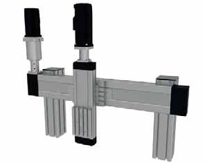
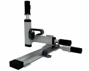
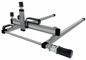
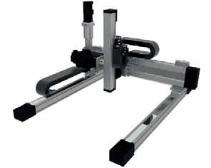
99 ACCESSORIES Multi Axis Systems We offer all neccessary fittings including brackets, clamping fixtures and adapter plates in order to build multiaxis systems. Beside standard elements we supply also custom fixing and connection elements manufactured in our workshop
100 ACCESSORIES
Any reproduction, even partial, is allowed only by written permission by Rollco.
 LINEAR UNIT E-SMART Every care has been taken to ensure the accuracy of the information contained in this catalogue, but no liability can be accepted for any errors or omissions. We reserve the right to
Compact Modules. with ball screw drive and toothed belt drive R310EN 2602 ( ) The Drive & Control Company
 The Drive & Control Company") with ball screw drive and toothed belt drive R310EN 2602 (2007.02) The Drive & Control Company Bosch Rexroth AG Linear Motion and Assembly Technologies Ball Rail Systems Roller Rail Systems Linear Bushings
with ball screw drive and toothed belt drive R310EN 2602 (2007.02) The Drive & Control Company Bosch Rexroth AG Linear Motion and Assembly Technologies Ball Rail Systems Roller Rail Systems Linear Bushings
Linear Drive with Toothed Belt and Integrated Guide with Recirculating Ball Bearing Guide with Roller Guide Series OSP-E..BHD
 Linear Drive with and Integrated Guide with Recirculating Ball Bearing Guide with Roller Guide Contents Description Page Overview 11-14 Version with Recirculating Ball Bearing Guide Technical Data 15-17
Product overview. 10 Bosch Rexroth Corporation Compact Modules R310A 2602 ( ) Compact Modules CKK. Compact Modules with ball screw drive (CKK)
 Compact Modules CKK. Compact Modules with ball screw drive (CKK)") 10 Bosch Rexroth Corporation R310A 2602 (2008.09) CKK with ball screw drive (CKK) Product overview are precision, ready-to-install linear motion systems characterized by their high performance and compact
10 Bosch Rexroth Corporation R310A 2602 (2008.09) CKK with ball screw drive (CKK) Product overview are precision, ready-to-install linear motion systems characterized by their high performance and compact
PNCE ELECTRIC CYLINDERS
 ELECTRIC CYLINDERS Every care has been taken to ensure the accuracy of the information contained in this catalogue, but no liability can be accepted for any errors or omissions. We reserve the right to
Linear Drive with Toothed Belt Series OSP-E..B. Contents Description Overview Technical Data Dimensions Order Instructions 46
 Linear Drive with Toothed Belt Contents Description Page Overview 35-38 Technical Data 39-43 Dimensions 44-45 Order Instructions 46 35 The System Concept ELECTRIC LINEAR DRIVE FOR POINT-TO-POINT APPLICATIONS
ELECTRIC ACTUATOR - RODLESS ELEKTRO SK SERIES ACTUATORS
 ELECTRIC ACTUATOR - RODLESS ELEKTRO SK SERIES 1 ELECTRIC AXIS - RODLESS ELEKTRO SK SERIES Electric axis without screw piston rod, with V-Lock interface. The cylinder frame is made of anodized extruded
Precision Modules PSK
 Precision Modules PSK 2 Bosch Rexroth AG Precision Modules PSK R999000500 (2015-12) Identification system for short product names Short product name Example:: P S K - 050 - N N - 1 System = Precision Module
Product Description. Characteristic features R310A 2402 ( ) Linear Modules MLR
 Linear Modules MLR") 9 Bosch Rexroth Corporation R310A 40 (1.11) MLR Product Description Characteristic features MLR...: with Cam Roller Guide and Toothed Belt Drive for high-speed applications (up to 10 m/s) with Cam Roller
9 Bosch Rexroth Corporation R310A 40 (1.11) MLR Product Description Characteristic features MLR...: with Cam Roller Guide and Toothed Belt Drive for high-speed applications (up to 10 m/s) with Cam Roller
Precision Modules PSK
 Precision Modules PSK The Drive & Control Company Rexroth Linear Motion Technology Ball Rail Systems Roller Rail Systems Standard Ball Rail Systems Super Ball Rail Systems Ball Rail Systems with Aluminum
Contents. Page. 1. Product description. 2. The AXC line of linear axes. 3. AXLT line of linear tables. AXC and AXS product overview...
 SNR Industry Contents Page 3 1. Product description AXC and AXS product overview... 6-8 Dynamic load ratings of the linear motion systems... 9 Compact modules... 10-11 Linear tables... 12 Telescopic axes...
Vertical Linear Drive with Toothed Belt and Integrated Recirculating Ball Bearing Guide Series OSP-E..BV
 Vertical Linear Drive with and Integrated Recirculating Ball Bearing Guide Series OSP-E..BV Overview...25-28 Technical Data...29-31 Dimensions...32-33 25 Features TOOTHED BELT DRIVE FOR VERTICAL MOVEMENTS
V SWISS MADE LINEAR TECHNOLOGY
 Compact units Excerpt from main catalogue SWISS MADE LINEAR TECHNOLOGY V 11-15 Line Tech compact units Table of contents Product overview 106 107 Design fundamentals / Lubrication / Maintenance 108 Profile
Vertical Linear Drive with Toothed Belt and Integrated Recirculating Ball Bearing Guide Series OSP-E..BV
 Vertical Linear Drive with Toothed Belt and Integrated Recirculating Ball Bearing Guide Series OSP-E..BV Contents Description Page Overview 25-28 Technical Data 29-33 Dimensions 34 Order Instructions 35
ELECTRIC AXIS ELEKTRO SVAK SERIES ACTUATORS
 ELECTRIC AXIS ELEKTRO SVAK SERIES 1 ELECTRIC AXIS ELEKTRO SVAK SERIES This belt-driven rodless electric actuator is characterised by the fact that the motor and reducer unit is integral with the carriage,
Precision Modules PSK. The Drive & Control Company
 Precision Modules PSK The Drive & Control Company 2 Bosch Rexroth Coporation Precision Modules PSK R310A 2414 (2008.07) Linear Motion and Assembly Technologies Ball Rail Systems Roller Rail Systems Linear
Vertical Linear Drive with Toothed Belt and Integrated Recirculating Ball Bearing Guide Series OSP-E..BV
 Vertical Linear Drive with and Integrated Recirculating Ball Bearing Guide Series OSP-E..BV Contents Description Page Overview 25-28 Technical Data 29-31 Dimensions 32-33 25 Parker Hannifin Corporation
Any reproduction, even partial, is allowed only by written permission by Rollco.
 LINEAR UNIT RHL Every care has been taken to ensure the accuracy of the information contained in this catalogue, but no liability can be accepted for any errors or omissions. We reserve the right to make
CKR Compact Modules with Ball Rail Guides and Toothed Belt Drive. The Drive and Control Company
 CKR Compact Modules with Ball Rail Guides and Toothed Belt Drive The Drive and Control Company Bosch Rexroth Corp. Linear Motion and Assembly Technologies CKR RE 8 615 (03.006) Rexroth Linear Motion Technology
A5 BELT-DRIVEN RODLESS ELECTRIC AXIS, SERIES ELEKTRO BK
 BELT-DRIVEN RODLESS ELECTRIC AXIS, SERIES ELEKTRO BK Belt-driven rodless electric axis with a V-Lock interface. The structure features an extremely lightweight yet high-strength anodised aluminium extruded
Any reproduction, even partial, is allowed only by written permission by Rollco.
 EASYSLIDE Every care has been taken to ensure the accuracy of the information contained in this catalogue, but no liability can be accepted for any errors or omissions. We reserve the right to make changes
Linear Drive with Ball Screw Drive Series OSP-E..SB
 Linear Drive with Ball Screw Drive Series OSP-E..SB Contents Description Data Sheet No. Page Overview 1.30.001E 47-50 Technical Data 1.30.002E-1 to 5 51-55 Dimensions 1.30.002E-6, -7 56-57 Order instructions
Ball rail actuator/guide - RK DuoLine Z/R
 Ball rail actuator/guide - RK DuoLine Z/R All-round talent with protected guide system Fixing slots in the guide profile and carriage 9Simple 9 connection of accessories 9Excellent 9 fixing options for
V SWISS MADE LINEAR TECHNOLOGY
 Excerpt from main catalogue inear modules V 11-15 SWISS MDE INER TECHNOOGY ine Tech inear modules Table of contents Product overview 6 7 Design fundamentals / ubrication / Maintenance 8 Profile cross-sections
Index INDEX. Product overview Technical data... 5 RHL Sliders for RHL80: V100, V250 & V RHL
 LINEAR UNIT RHL Svanemærket tryksag 541-713 INDEX Index Product overview... 4 Technical data... 5 RHL... 6 Sliders for RHL: V1, V25 & V5... 7 RHL11... 8 Sliders for RHL11: V2 & V5... 9 Mounting Plates...
Linear Actuator with Toothed Belt Series OSP-E..B
 Linear Actuator with Toothed Belt Series OSP-E..B Contents Description Data Sheet No. Page Overview 1.20.001E 21-24 Technical Data 1.20.002E-1 to 5 25-29 Dimensions 1.20.002E-6 30 Order Instructions 1.20.002E-7
1. Product overview Basic-Line-Module AXN Product description Basic-Line-Module AXN 4-5. Guide system Roller guide 6 Drive system Gear belt 7
 Directory Page 1. Product overview Basic-Line-Module AXN 3 2. Product description Basic-Line-Module AXN 4-5 Guide system Roller guide 6 Drive system Gear belt 7 3. Basic-Line-Modul AXN 45-Z 8-9 AXN 65-Z
124
 124 www.danahermotion.com Linear Units Linear Rod Units VarioLine, Movotrak Linear units with rod Perfect for hydraulics and pneumatics replacement Load up to 40 000 N High accuracy ball screw drive High
Linear Actuator with Toothed Belt and Integrated Roller Guide Series OSP-E..BHD
 inear Actuator with Toothed Belt and Integrated Roller Guide Series OSP-E..BHD Contents Description Data Sheet No. Page Overview 1.15.001E 11-14 Technical Data 1.15.002E-1 to 3 15-17 Dimensions 1.15.002E-4
Compact Modules CKK/CKR 9-70
 Compact Modules CKK/CKR 9-70 (with Ball Rail System, Ball Screw Drive or Toothed Belt Drive) R310EN 2624 (2008.10) The Drive & Control Company Bosch Rexroth AG Linear Motion and Assembly Technologies Ball
Linear Actuator with Ball Screw Series OSP-E..S. Contents Description Overview Technical Data Dimensions 89
 Linear Actuator with Ball Screw Series OSP-E..S Contents Description Page Overview 79-82 Technical Data 83-88 Dimensions 89 79 The System Concept ELECTRIC LINEAR ACTUATOR FOR HIGH ACCURACY APPLICATIONS
ISOMOVE. Mechanical actuators ISO 6431
 ISOMOVE Mechanical actuators ISO 6431 ISOMOVE INDEX 2 Introduction 4 Mounting information and advices 6 10 40 14 20 63 25 80 29 33 Overall dimensions INTRODUCTION GENERAL FEATURES The ISOMOVE actuators
TELESCOPIC RAIL HEAVY
 TELESCOPIC RAIL HEAVY Every care has been taken to ensure the accuracy of the information contained in this catalogue, but no liability can be accepted for any errors or omissions. We reserve the right
Sizes 50, 65, 80. Presence of internal channels for re-lubrication Large range of axis mounting accessories
 > Series 5E electromechanical axis C_Electrics > 207 Series 5E electromechanical axis New models Sizes 50, 65, 80 Multiposition system with transmission of the movement with toothed belt Suitable for high
Max. particle size 5 µm. Pressure for determining piston forces. Materials:
 Rodless cylinders Rodless cylinder 1 Working pressure min./max. 2 bar / 8 bar Ambient temperature min./max. -10 C / +60 C Medium Compressed air Max. particle size 5 µm Oil content of compressed air 0 mg/m³
Toothed belt axes DGE
 Toothed belt axes DGE Toothed belt axes DGE Key features At a glance Precision, rigid guide Highly adaptable, thanks to wide choice of mounting and attachment options Wide range of options for attaching
linear units control in motion
 linear units control in motion by 2 Almotion b.v. Nijverheidsweg 14 6662 NG ELST (Gld.) The Netherlands +31 488 480858 +31 488 481 1 65 info@almotion.nl www.almotion.nl www. lineair.nl www.lineairegeleiding.nl
Sizes 50, 65, 80. Accessories for cables fixing. Presence of internal channels for re-lubrication Large range of axis mounting accessories
 > Series 5E electromechanical axis C_Electrics > 206 Series 5E electromechanical axis New Sizes 50, 65, 80 Multiposition system with transmission of the movement with toothed belt Suitable for high dynamics
Roller guide actuator/guides - SQ /SQZ
 Roller guide actuator/guides - SQ /SQZ Timing-belt unit with optimum connecting options due to slots in guide profile/carriage Fixing slots 9Easy 9 fixing of linear actuator 9Simple 9 connection of accessories
Linear Actuator with Ball Screw Series OSP-E..S. Contents Description Overview Technical Data Dimensions 79
 Linear Actuator with Ball Screw Series OSP-E..S Contents Description Page Overview 71-74 Technical Data 75-78 Dimensions 79 71 The System Concept ELECTRIC LINEAR ACTUATOR FOR HIGH ACCURACY APPLICATIONS
ORIGA Pneumatic Linear Drives OSP-L
 ORIGA Pneumatic Linear Drives OSP-L Very long lifetime and lowest leakage A NEW Modular Linear Drive System With this second generation linear drive Parker Origa offers design engineers complete flexibility.
RE-CIRCULATING BALL BEARING LINEAR GUIDES (SERIES LP)
") RE-CIRCULATING BALL BEARING (SERIES ) Patented re-circulating ball bearing guide system. Several T-nut mounting options. Optional mounting accessory kits are available. More than one carrier per rail can
RE-CIRCULATING BALL BEARING (SERIES ) Patented re-circulating ball bearing guide system. Several T-nut mounting options. Optional mounting accessory kits are available. More than one carrier per rail can
WIESEL SPEEDLine WHZ80 with roller guideway and AT toothed belt
 WIESEL WHZ80 with roller guideway and AT toothed belt All figures shown in millimeters. Note: Mounted wipers on request. The use of a long power bridge increases the total length. Technical data Linear
SNR, YOUR GUIDE TO LINEAR MODULES
 SNR, YOUR GUIDE TO LINEAR MODULES A bearing manufacturer known across the world For almost a century NTN-SNR has been focusing on the development, design and manufacture of bearings. Today NTN-SNR has
ACTUATORLINE ELM series
 ACTUATORLINE ELM series www.rolloncorp.com www.motiontech.com.au Contents Series Overview 1 The Components 2 The Linear Motion System 3 Main Technical Characteristics 4 ELM 50 SP 6 ELM 65 SP 7 ELM 80 SP
Catalogue. Portal Axes PAS
 Catalogue Portal xes PS Portal xes PS Table of Content Product Description............................... 2 Ballscrew axes.................................... Product description.............................
Cam roller guide LF12S complete axis
 Y -16 MGE. Linear guides Z Mz Cam roller guide LF1S complete axis X Mx M y [mm] B [mm] Fully assembled cam roller guide Stroke and trolley length can be individually selected Rail profile screwed onto
Linear Actuator with Toothed Belt and Integrated Guide with Roller Guide with Recirculating Ball Bearing Guide. Series OSP-E..BHD
 inear ctuator with Toothed elt and Integrated Guide with Roller Guide with Recirculating all earing Guide Series OSP-E..HD Contents Description Page Overview 11-14 Version with Roller Guide Technical Data
ML Series MINIATURE SCREW-DRIVEN LINEAR ACTUATOR LOW COST SOLUTION FOR PRECISION POSITIONING IN COMPACT SPACES!
 ML Series MINIATURE SCREW-DRIVEN LINEAR ACTUATOR Compact and easy to install, a low cost linear solution perfectly suited for the medical industry, life science and small scale automation applications.
LM SERIES LINEAR MODULE
 LM SERIES LINEAR MODULE THE LM RODLESS LINEAR ACTUATOR RACO s LM Linear Modules are lightweight positioning elements, which can be easily configured into a wide variety of multiple axis motion systems.
PNCE ELECTRIC CYLINDER
 ELECTRIC CYLINDER INDEX Characteristics 1 Structural design 2 How to order 3 Technical data 4 Dimensions 11 Accessories 12 Lubrication position 2 Motor adapter with coupling 2 Motor side drive with timing
Introduction. Stainless Steel Cover. Removable Carriage Plate. Mounting Platform. Limit Switch & Bracket. Aluminum Beam.
 Introduction The HepcoMotion SBD is an exceptionally rugged, quiet and precise linear unit. It uses super-smooth Hepco LBG caged linear ball guides having such high load capacity that system life is rarely
Linear Guides Series OSP-E
 Linear Guides Series OSP-E NEW Contents Description Data Sheet No. Page Overview 1.40.020E 101-102 Plain Bearing SLIDELINE 1.40.021E 103-104 Roller Guide POWERSLIDE 1.40.022E 105-108 Aluminium Roller Guide
Roller guide actuators - SQ ZST
 Roller guide actuators - SQ ZST Rack and pinion with fixed carriage, also for larger travels up to 30 m RK Standard motor 9Choice 9 of motor and motor adaptor plate to suit your requirements 9 9Simple
ndustr SNR our guide to linear modules
 ndustr SNR our guide to linear modules SNR A bearing manufacturer known across the world For almost a century SNR has been focusing on the development, design and manufacture of bearings. Today SNR has
GRIPPERS SERIES P3 - P12 ACTUATORS
 GRIPPERS SERIES P3 - P12 1 GRIPPER WITH TWO PARALLEL JAWS, SERIES P3 GRIPPER WITH TWO PARALLEL JAWS, SERIES P3 Parallel double-acting two-jaw gripper, with either internal or external clamping. Body made
STAR Ball Rail Tables TKK
 before operating X4 X8 X3 X1 X2 S1 S2 12 4 13 5 14 6 15 7 16 8 1 2 3 9 10 11 1 2 3 4 5 6 8.8 S3 X30 Indramat DANGER! AC-CONTROLLER High voltage Danger of electrical shock Do not touch electrical connnections
MTB 42 Belt Driven Linear Actuator
 LINEAR ACTUATOR TECHNOLOGY MT Series MTB Belt Driven Linear Actuator The MT Series offers a number of profile sizes with multiple design configurations to fit almost any application. TECHNICAL DATA features
Compact Modules CKK/CKR 9-70
 Compact Modules CKK/CKR 9-70 with Ball Screw Drive and Toothed Belt Drive The Drive & Control Company 2 Compact Modules CKK/CKR 9-70 R310A 2624 (2009.05) Linear Motion and Assembly Technologies Ball Rail
Parallel Grippers. Body One piece anodized aluminum body
 Catalog 19-2/US Features Rack and Pinion Rack and pinion drive mechanism provides synchronous motion. Body One piece anodized aluminum body Bushings Four composite bushings provide the support needed for
WIESEL POWERLine and WIESEL DYNALine with ball screw drive Innovative solutions, down to the very last detail.
 WIESEL POWERLine and WIESEL DYNALine with ball screw drive Innovative solutions, down to the very last detail. WIESEL POWERLine WM40 The linear drive unit for miniaturized applications. High performance
OSP-E Series Electric Linear Drives and Guides ENGINEERING YOUR SUCCESS. Catalog aerospace. electromechanical
 aerospace climate control electromechanical filtration fluid & gas handling hydraulics pneumatics process control sealing & shielding OSP-E Series Electric Linear Drives and Guides Catalog 0950-2 ENGINEERING
Берг АБ Тел. (495) , факс (495)
 , факс (495)") AUTOMATION Linear- and Rotary Modules Table of Contents 1 Product Overview............................................. 4 1.1 Selection of the Linear Modules................................. 8 1.2 Selection
AUTOMATION Linear- and Rotary Modules Table of Contents 1 Product Overview............................................. 4 1.1 Selection of the Linear Modules................................. 8 1.2 Selection
RODLESS CYLINDER SERIES PU ACTUATORS
 RODLESS CYLINDER SERIES PU 1 RODLESS CYLINDER SERIES PU RODLESS CYLINDER SERIES PU Series PU rodless cylinders have an internal strip for longitudinal tightness made of polyurethane (PU) with a harmonic
DGE Linear Actuators. Belt and Ball Screw Driven. Info 130 US
 DGE Linear Actuators Belt and Ball Screw Driven Belt Driven Linear Actuators Sizes: 8, 12, 18, 25, 40, 63 Stroke Lengths up to 5 m Maximum Speed: 10 m/s Repeatability of ±0.10 mm Axial force up to 1,500
TRACK GUIDANCE SYSTEMS
 EURO-BEARINGS LTD TRACK GUIDANCE SYSTEMS www.euro-bearings.com Tel. 01908 511733 email: sales@euro-bearings.com INTRODUCTION EURO-BEARINGS LTD www.euro-bearings.com Tel. 01908 511733 This linear guidance
MT Series MTB 42 BELT DRIVEN LINEAR ACTUATOR
 MT Series MTB BELT DRIVEN LINEAR ACTUATOR LINEAR ACTUATOR TECHNOLOGY The MT Series offers a number of profile sizes with multiple design configurations to fit almost any application. TECHNICAL DATA FEATURES
Active and Passive Brakes Series OSP-P
 Active and Passive Brakes Series OSP-P Contents Description Page Overview 51-52 Standard cylinder with Active brake 53-56 Plain bearing SLIDELINE with Active brake 33-34 Aluminium roller guide PROLINE
LINEAR RAIL BALL CHAIN TYPE
 LINEAR RAIL BALL CAIN TYPE Svanemærket tryksag 54-73 INDEX Index Product overview... 4-5 Dimension table RC/ERC... 6-7 Dimension table RC... 8-9 Dimension table ARC... 0-3 Dimension table & Grease... 4
Modular Electric Actuators OSP-E ORIGA SYSTEM PLUS
 Modular Electric Actuators OSP-E ORIGA SYSTEM PLUS Contents Modular Electric Actuators OSP Concept Origa System Plus Electric Actuator OSP-E, Modular Components - Overview Page 4 Applications for OSP-E
R310EN 2211 ( ) The Drive & Control Company
 The Drive & Control Company") eline Ball Rail Systems R310EN 2211 (2006.04) The Drive & Control Company Bosch Rexroth AG Linear Motion and Assembly Technologies Ball Rail Systems Roller Rail Systems Linear Bushings and Shafts Ball
eline Ball Rail Systems R310EN 2211 (2006.04) The Drive & Control Company Bosch Rexroth AG Linear Motion and Assembly Technologies Ball Rail Systems Roller Rail Systems Linear Bushings and Shafts Ball
LM-P608 Portal Axis. Features. Versions
 The LM-P608 portal axis is the universally suitable axis from our linear axis program. With a profile cross section of 80 x 80mm and a permissible load of up to 60 kg it meets the demands of the applications
Modular Electrical Linear Drives Catalog 0950
 aerospace climate control electromechanical filtration fluid & gas handling hydraulics pneumatics process control sealing & shielding Modular Electrical Linear Drives Catalog 0950 OSP-E Series Electric
SERIES RTC RODLESS CYLINDERS PNEUMATIC SHUTTLE TYPE
 SERIES RTC RODLESS CYLINDERS PNEUMATIC SHUTTLE TYPE Series RTC Rodless Cylinder Pneumatic automation building block Series RTC (Rodless Thrust Cylinder)-High performance shuttle type rodless cylinders
96
 96 www.danahermotion.com Linear Units Linear Units with Belt Drive and Wheel Guide SpeedLine, ForceLine Velocity Noise Acceleration Maintenance Repeatability Cost Force Guide Robustness Load Torque Stiffness
Sizes 32, 40, 50 and 63
 > Series 6E electromechanical cylinders C_Electrics > 207 Series 6E electromechanical cylinders Sizes 32, 40, 50 and 63 The Series 6E cylinders are mechanical linear actuators with rod, in which the rotary
mechanics LES functional overview LES 4 LES 6 LES 5
 LES functional overview LES 4 Overview B-36 B-38 with spindle drive LES 6 B-40 with spindle drive LES 5 B-42 with spindle drive Combination examples Motor modules Clutch housing Motor leads Installation
Rexroth Linear Motion Technology
 Linear Modules Robotic Erector System for Linear Modules RE 82 402/2003-10 The Drive & Control Company 1 RE 82 402/2003-10 Rexroth Linear Motion Technology Ball Rail Systems Roller Rail Systems Standard
Cam roller guide LF6S complete axis
 Y 1- MGE 1. Linear guides Z Mz Cam roller guide LFS complete axis X Mx M y [mm] B [mm] Fully assembled cam roller guide Stroke and trolley length can be individually selected Rail profile screwed onto
RE-CIRCULATING BALL BEARING LINEAR GUIDES (SERIES LM)
") LM RE-CIRCULATING BALL BEARING (SERIES LM) Patented re-circulating ball bearing guide system. Several T-nut mounting options. Optional mounting accessory kits are available. Available in any length up
LM RE-CIRCULATING BALL BEARING (SERIES LM) Patented re-circulating ball bearing guide system. Several T-nut mounting options. Optional mounting accessory kits are available. Available in any length up
OSPE..BHD Belt-Driven Actuators
 OSPE..BHD Belt-Driven Actuators Actuators for High-Speed, Long Travel, Heavy Duty Applications The OSPE..BHD is the highest capacity belt-driven actuator in the OSPE family. The integrated ball bearing
Miniature Linear Modules MKK/MKR The Drive & Control Company
 Miniature Linear Modules MKK/MKR 12-40 The Drive & Control Company 2 Miniature Linear Modules R310A 2418 (2009.05) Linear Motion and Assembly Technologies Ball Rail Systems Roller Rail Systems Linear Bushings
mechanics LES functional overview LES 4 LES 6 LES 5
 LES functional overview LES 4 with spindle drive Overview 2-54 2-56 LES 6 2-58 with spindle drive LES 5 2-60 with spindle drive Calculations 2-62 Combination examples Motor modules Clutch housing Motor
 www.motiontech.com.au Copyright SERVOMECH This catalogue contents are under publisher copyright and may not be reproduced unless permission is agreed. Every care has been taken to ensure the accuracy of
LAP4, LAP8. Pneumatic linear drive sizes 4 and 8
 Pneumatic linear drive sizes 4 and Torsional and bending resistant profiles T-slots in the outer profile enable individual mounting options Adjustable guiding system (LAP4) Precise linear roller guiding
Ball Rail Systems RE / The Drive & Control Company
 Ball Rail Systems RE 82 202/2002-12 The Drive & Control Company Rexroth Linear Motion Technology Ball Rail Systems Roller Rail Systems Standard Ball Rail Systems Super Ball Rail Systems Ball Rail Systems
RE-CIRCULATING BALL BEARING LINEAR GUIDES (SERIES LL)
") LL RE-CIRCULATING BALL BEARING (SERIES LL) Patented re-circulating ball bearing guide system. Excellent price / performance ratio. Several T-nut mounting options. Optional mounting accessory kits are available.
LL RE-CIRCULATING BALL BEARING (SERIES LL) Patented re-circulating ball bearing guide system. Excellent price / performance ratio. Several T-nut mounting options. Optional mounting accessory kits are available.
TELESCOPIC RAILS HARDENED TELESCOPIC RAILS FOR HIGHLY DYNAMIC APPLICATIONS 7.1 PRODUCT OVERVIEW 7.2 PART EXTENSIONS 7.
 7 TELESCOPIC RAILS HARDENED TELESCOPIC RAILS FOR HIGHLY DYNAMIC APPLICATIONS PAGE 106 PAGE 116 PAGE 120 PAGE 126 7.1 PRODUCT OVERVIEW 7.2 PART EXTENSIONS 7.3 FULL EXTENSIONS 7.4 LINEAR GUIDES 105 PRODUCT
Portal modules.
 Portal modules www.comoso.com www.comoso.com Portal modules PORTAL MODULES Series Size Page Portal modules PMP 114 PMP 16 118 PMP 25 124 EPM 130 EPM 37 138 EPM 48 146 The SCHUNK program offers linear technology
Type SFKR - single nut with flange Type RSKR - single nut, cylindrical with thread Type RSCR - single nut, cylindrical with thread...
 BALL SCREWS Svanemærket tryksag 541-713 INDEX Index Type SFKR - single nut with flange... 4 Type RSKR - single nut, cylindrical with thread... 5 Type RSCR - single nut, cylindrical with thread... 6 Type
Courtesy of CMA/Flodyne/Hydradyne Motion Control Hydraulic Pneumatic Electrical Mechanical (800)
") 01_1 Miniature st Headline_36 Ball Rail pt/14.4 Systems mm second line 2 Linear Motion and Assembly Technologies Miniature Ball Rail Systems Ball Rail Systems Roller Rail Systems Linear Bushings and Shafts
01_1 Miniature st Headline_36 Ball Rail pt/14.4 Systems mm second line 2 Linear Motion and Assembly Technologies Miniature Ball Rail Systems Ball Rail Systems Roller Rail Systems Linear Bushings and Shafts
Modular Electric Actuators OSP-E ORIGA SYSTEM PLUS
 Modular Electric Actuators OSP-E ORIGA SYSTEM PLUS Sizing Performance Overview Maximum Loadings Sizing of Actuator The following steps are recommended for selection : 1. Check that maximum values in the
Linear actuator with integral planetary gearbox and servomotor
 Linear actuator with integral planetary gearbox and servomotor Series MLF 52155 ZR.. GTRI/.., MKUSE 25 ZR.. GTRI/.. Linear actuators with an integral gearbox and motor are ready-to-fit, driven linear units
The new performance class...
 The new performance class... 10/2017 EP(X)-II 30/40 EP(X)-II 30/40 twin tube actuator The latest generation of twin tube units Move-Tec EP(X)-II 30/40 Your application takes centre stage slow langsam A
ORIGA SYSTEM PLUS OSP-P
 ORIGA SYSTEM PLUS OSP-P The ORIGINAL rodless pneumatic cylinders A NEW Modular Linear Drive System With this second generation linear drive Parker Origa offers design engineers complete flexibility. The
Miniature Ball Rail Systems
 R310EN 2210 (2004.06) The Drive & Control Company 2 Bosch Rexroth AG Linear Motion and Assembly Technologies Miniature-BRS R310EN 2210 (2004.06) Linear Motion Systems Ball Rail System Standard Ball Rail
EMC-HD. C 01_2 Subheadline_15pt/7.2mm
 C Electromechanical 01_1 Headline_36pt/14.4mm Cylinder EMC-HD C 01_2 Subheadline_15pt/7.2mm 2 Elektromechanischer Zylinder EMC-HD Short product name Example: EMC 085 HD 1 System = ElectroMechanical Cylinder
Linear Guides Series OSP-P
 Linear Guides Series OSP-P NEW Contents Description Page Overview 31-32 Plain bearing guide SLIDELINE 33-34 Roller guide POWERSLIDE 35-38 Aluminium roller guide PROLINE 39-40 Recirculating ball bearing
506E. LM Guide Actuator General Catalog
 LM Guide Actuator General Catalog A LM Guide Actuator General Catalog A Product Descriptions 506E Caged Ball LM Guide Actuator Model SKR.. A2-4 Structure and Features... A2-4 Caged Ball Technology... A2-6
Index. Order Code INDEX PRODUCT OVERVIEW AND ORDER CODE
 LINEAR UNIT QME vanemærket tryksag 541-713 INDEX PRODUCT OVERVIEW AND ORDER CODE Index Product overview and order code... 3-4 Diagram all types... 5 ellow and adjustment wheel... 6 Product overview...