Precision Modules PSK. The Drive & Control Company
|
|
|
- Octavia Carr
- 6 years ago
- Views:
Transcription


1 Precision Modules PSK The Drive & Control Company


2 2 Bosch Rexroth Coporation Precision Modules PSK R310A 2414 ( ) Linear Motion and Assembly Technologies Ball Rail Systems Roller Rail Systems Linear Bushings and Shafts Ball Screw Drives Linear Motion Systems Basic Mechanical Elements Manual Production Systems Transfer Systems Ball Rail Systems Roller Rail Systems Linear Bushings and Shafts Ball Screw Drives Linear Motion Systems Basic Mechanical Elements Manual Production Systems Assembly Conveyors VarioFlow Conveyors
3 R310A 2414 ( ) Precision Modules PSK 3 Precision Modules PSK Product Description 4 Product Overview 6 Motor selection 6 Overview of types with load capacities 8 Dimensions 9 Structural Design 10 PSK without cover 10 PSK with cover plate 10 PSK with sealing strip 11 Attachments for all PSK modules 11 Technical Data 14 Technical Data, Calculations 20 Calculation Example 23 Accuracy 25 Precision Module PSK Components and Ordering Data 26 Lengths and Hole Spacing 28 Dimension Drawings without Cover 29 Dimension Drawings with Cover Plate 30 Dimension Drawings, Motor Attachment 31 Precision Module PSK Components and Ordering Data 32 Lengths and Hole Spacing 34 Dimension Drawings without Cover 35 Dimension Drawings with Cover Plate 36 Dimension Drawings with Sealing Strip 37 Dimension Drawings, Motor Attachment 38 Precision Module PSK Components and Ordering Data 40 Lengths and Hole Spacing 42 Dimension Drawings without Cover 43 Dimension Drawings with Cover Plate 44 Dimension Drawings with Sealing Strip 45 Dimension Drawings, Motor Attachment 46 Präzisionsmodul PSK Components and Ordering Data 48 Lengths and Hole Spacing 50 Dimension Drawings without Cover 51 Dimension Drawings with Cover Plate 52 Dimension Drawings with Sealing Strip 53 Dimension Drawings, Motor Attachment 54 Switch Mounting Arrangements 56 Motors 59 AC Servo Motors MSK 59 AC Servo Motors MSM 60 3-phase Stepping Motors VRDM 61 Mounting 62 Lube Ports 63 Documentation 64 Inquiry/Order Form 67
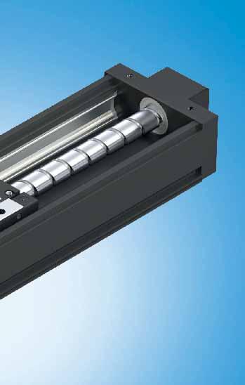
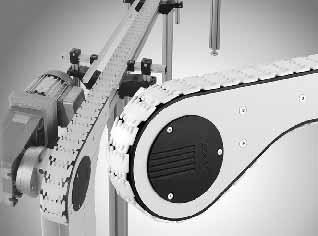
4 4 Bosch Rexroth Coporation Precision Modules PSK R310A 2414 ( ) Product Description Outstanding features Rexroth Precision Modules are precise, ready-to-install linear motion systems that combine high performance with compact dimensions. Rexroth offers favorable price/performance ratios and fast delivery. Structural design Extremely compact and rigid precision steel profi le (frame) with reference edge and integrated Rexroth guideway geometry Precision ball screw drive in tolerance grade 7 with zerobacklash nut system Aluminum fi xed bearing end block with preloaded ball bearings and ball screw journal Floating bearing end block with double ball bearings One or two steel carriages, standard length or long, for PSK without cover or with cover plate One aluminum carriage, standard length or long, for PSK with sealing strip Attachments Maintenance-free digital AC servo drives with integrated brake and attached feedback, or stepper motors Motor mount and coupling or timing belt side drive for motor attachment Adjustable switches over the entire travel range Aluminum profi le cable duct Further highlights Extremely stiff and precise miniature drive unit Optimal travel performance, high load capacities, high precision and high rigidity due to integrated Rexroth Ball Rail System High positioning accuracy and repeatability due to Precision Ball Screw Assembly with zero-backlash nut system Repeatability up to mm Positioning accuracy up to 0.01 mm Travel accuracy up to mm High travel speeds combined with high precision due to Ball Rail Systems, large screw diameters and leads, and double fl oating bearing Rapid mounting and easy axis alignment thanks to machined reference edge on the frame Precise alignment and secure mounting of attachments thanks to tapped bores and pin holes in the carriage Easy motor attachment via locating feature and fastening threads Low-cost maintenance provided by one-point lubrication (grease) for Ball Rail System and Precision Ball Screw Assembly Precision Modules in standard lengths for fast delivery Drive controllers and control systems Fixed bearing end block with ball screw journal Fixed bearing end block with integrated motor mount For mounting, maintenance and start-up, see Instructions for Precision Modules PSK.
 Precision Modules PSK 5 PSK")


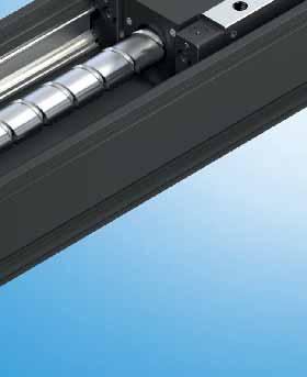
5 R310A 2414 ( ) Precision Modules PSK 5 PSK without cover Internal elements protected by cover plate One or two steel carriages, standard length or long Internal elements protected by stainless steel sealing strip Aluminum carriage, standard length or long
 Product Overview Motor selection Based on drive controllers and control system A choice can be made between several different motor/controller combinations to achieve the most")

6 Hand RS232 Auto 6 Bosch Rexroth Coporation Precision Modules PSK R310A 2414 ( ) Product Overview Motor selection Based on drive controllers and control system A choice can be made between several different motor/controller combinations to achieve the most cost-effi cient solution for each customer application. When sizing the drive, always consider the motor-controller combination. For more information about motors and control systems, see the following Rexroth catalog: IndraDrive for Linear Motion Systems Digital AC servo motors MSK Digital controllers IndraDrive Digital AC servo motors MSM Digital controllers ECODRIVE Cs 3-phase stepping motors VRDM Power electronics SD326 SD328 Twin Line Profi Step control unit


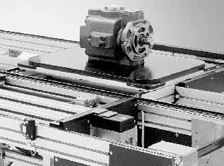
7 R310A 2414 ( ) Precision Modules PSK 7 Precision Modules PSK can be supplied complete with motor, drive and control unit.
8 8 Bosch Rexroth Coporation Precision Modules PSK R310A 2414 ( ) Product Overview Type designation (size) Precision Modules are designated according to type and size. Types also cover the equivalent designs without drive systems. Description Type Size Example: Precision Module P S K 60 System Precision Module (P) Guideway Integrated Ball Rail System (S) Drive unit Precision Ball Screw Assembly (K) Frame size Approx. width of frame (mm) Example: B = 60 mm B Overview of types with load capacities Type System Guideway Drive unit 1) Size Cover Carriage (carr.) Load capacities PSK Precision Module Rail System Precision Ball Screw Assembly PSK 40 PSK 50 PSK 60 PSK 90 Without / cover plate Without / cover plate Sealing strip Without / cover plate Sealing strip Without / cover plate Sealing strip Number C (N) Standard 1 carr carr Standard 1 carr carr Standard 1 carr Long 1 carr Standard 1 carr carr Long 1 carr carr Standard 1 carr Long 1 carr Standard 1 carr carr Long 1 carr carr Standard 1 carr Long 1 carr ) All Precision Modules can also be supplied without drive unit. Permissible loads Suitable loads (recommended values) With respect to the desired service life, loads up to about 20% of the characteristic dynamic values (C, M t, M L ) have proven acceptable. At the same time, the following may not be exceeded: maximum permissible loads permissible drive torque permissible travel speed For permissible values, see the Technical Data section.
9 R310A 2414 ( ) Precision Modules PSK 9 Dimensions B L C C C C H Standard lengths L Precision Module PSK 40 PSK 50 PSK 60 PSK 90 B (mm) H (mm) L (mm)

 Structural Design PSK without")


10 10 Bosch Rexroth Coporation Precision Modules PSK R310A 2414 ( ) Structural Design PSK without cover 1 Fixed bearing end block 2 Ball screw with zero-backlash cylindrical single nut 3 One or two steel carriages, standard length or long 4 Floating bearing end block 5 Frame with reference edge and integrated guideway geometry PSK with cover plate 6 Cover plate 7 One or two carriages, standard length or long 8 Carriage plate, aluminum 9 Carriage, steel 1 carriage, standard length 4 1 carriage, standard length carriages, standard length 2 carriages, standard length 1 carriage, long 1 carriage, long 2 carriages, long 2 carriages, long
 Precision Modules PSK 11 PSK with sealing strip 10 Sealing strip, stainless")

11 R310A 2414 ( ) Precision Modules PSK 11 PSK with sealing strip 10 Sealing strip, stainless steel 11 One carriage, standard length or long 12 Carriage plate, aluminum 13 Carriage, aluminum Attachments for all PSK modules 14 Switches 15 Cable duct 16 Switching cam 1 carriage, standard length carriage, long
 Structural Design Fixed bearing end block A B Version with ball screw journal (A) 1 End block with preloaded bearing 2 Tapped mounting hole 3 Centering feature Version with integrated motor mount")
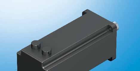
12 12 Bosch Rexroth Coporation Precision Modules PSK R310A 2414 ( ) Structural Design Fixed bearing end block A B Version with ball screw journal (A) 1 End block with preloaded bearing 2 Tapped mounting hole 3 Centering feature Version with integrated motor mount (B) 1 End block with integrated motor mount and preloaded bearing 2 Tapped mounting hole 3 Centering feature 4 Flange for motor attachment Motor attachment Motor attachment with motor mount and coupling A motor can be attached to all Precision Modules by means of a motor mount and coupling. The motor mount serves to fasten the motor to the Precision Module and acts as a closed housing for the coupling. The coupling transmits the motor drive torque free of distortive stresses to the Precision Module s ball screw journal. 1 2 Fixed bearing end block with integrated motor mount and coupling 1 Motor 2 Fixed bearing end block with integrated motor mount 3 Coupling 5 Precision module Fixed bearing end block with attached motor mount and coupling 1 Motor 3 Coupling 4 Fixed bearing end block 5 Precision module 6 Motor mount

13 R310A 2414 ( ) Precision Modules PSK 13 Motor attachment with timing belt side drive On Precision Modules PSK 60 and PSK 90 the motor (9) can be attached via a side drive with timing belt. This makes the overall length shorter than when attaching the motor with a motor mount and coupling. The compact, closed housing protects the belt and secures the motor The following gear ratios are available: i = 1 : 1 i = 1 : 1.5 The timing belt side drive can be mounted in four different directions: top, bottom left, right Precision module End cover Cover plate Drawn, anodized aluminum profi le Ball screw journal with support bearing Toothed belt Pre-tensioning of the toothed belt: Apply pretensioning force F pr to motor (F pr will be indicated on delivery) Belt pulleys AC servo motor F pr
14 14 Bosch Rexroth Coporation Precision Modules PSK R310A 2414 ( ) Technical Data Dynamic characteristics Precision Module PSK 40 PSK 50 PSK 60 PSK 90 Type of Carriage (carr.) Guideway Ball screw Fixed bearing cover Number Dynamic load capacity Dynamic load moments Size Dynamic load capacity Dynamic load capacity C (N) M t (Nm) M L (Nm) d 0 x P C (N) C (N) W/o and Standard 1 carr x w/plate 2 carr x l m 6 x W/o and Standard 1 carr x w/plate 2 carr x l m 8 x Strip Standard 1 carr x Long 1 carr x W/o and Standard 1 carr x w/plate 2 carr x l m 12 x Long 1 carr x carr x l m 12 x Strip Standard 1 carr x Long 1 carr x W/o and w/plate Standard 1 carr x carr x l m 16 x Long 1 carr x carr x l m 16 x Strip Standard 1 carr x Long 1 carr x l m = center-to-center distance between carriages (mm) d 0 = screw diameter (mm) P = screw lead (mm) carr. = carriage(s) (mm) m ca = moved mass of system (kg) General technical data Precision Module Planar moment of inertia Minimum center-to-center distance l m min Mass of the linear motion system m s (kg) I y I z Standard carr. Long carr. Without cover, without drive Without cover, with drive With cover plate With sealing strip (cm 4 ) (cm 4 ) (mm) (mm) PSK L + m ca L m ca m ca PSK L + m ca L m ca L m ca L m ca PSK L + m ca L m ca L m ca L m ca PSK L + m ca L m ca L m ca L m ca y z z y Mass Mass calculation without motor and switches. Mass formula: Mass factor (kg/mm) length L (mm) + mass of all parts of fi xed length (kg) + moved mass of system m ca (kg) Modulus of elasticity E E = 210,000 N/mm 2
15 R310A 2414 ( ) Precision Modules PSK 15 Note on dynamic load capacities and moments Determination of the dynamic load capacities and moments is based on a travel life of 100,000 m. Often only 50,000 m are actually stipulated. For comparison: Multiply values C, M t and M L from the table by y M L /M z max z F z max M t / M x max x Maximum permissible loads The maximum permissible forces (F y max, F z max ) and moments (M x max, M y max, M z max ) are equal to half the dynamic characteristics (C, M t, M L ). M L /M y max F y max l m Suitable loads (recommended values) With respect to the desired service life, loads up to about 20% of the characteristic dynamic values (C, M t, M L ) have proven acceptable. At the same time, the following may not be exceeded: maximum permissible loads permissible drive torque permissible travel speed l m = center-to-center distance between carriages (mm) Moved mass of system m ca Precision Carriage Moved mass of system m ca (kg) Module Without cover, without drive Without cover, with drive With cover plate With sealing strip 1 carr. 2 carr. 1 carr. 2 carr. 1 carr. 2 carr. 1 carr. PSK 40 Standard PSK 50 Standard Long 0.37 PSK 60 Standard Long PSK 90 Standard Long carr. = carriage(s) (mm)
16 16 Bosch Rexroth Coporation Precision Modules PSK R310A 2414 ( ) Technical Data Maximum permissible drive torque for mechanical system M mech PSK 40 Ball screw 6x2 The values shown for M mech are applicable under the following conditions: Horizontal operation Ball screw journal without keyway No radial load on ball screw shaft Consider the rated torque of the coupling used! M mech (Nm) L (mm) 1.2 PSK M mech (Nm) Ball screw 8x L (mm) M mech (Nm) PSK 60 Ball screw 12x10 12x5 12x2 Ball screw journal with keyway For PSK 90: If a keyway is used, when comparing the chart against the table, the lower of the two values will always apply! Precision Module M mech (Nm) PSK M mech = maximum permissible drive torque for mechanical system (N) L = PSK length (mm) Ball screw = ball screw size: d 0 x P d 0 = screw diameter (mm) P = lead (mm) M mech (Nm) L (mm) PSK 90 Ball screw 16x16 16x10 16x L (mm)
17 R310A 2414 ( ) Precision Modules PSK 17 Maximum permissible linear speed of mechanical system v mech 0.4 PSK 40 Ball screw 6x2 Consider the motor speed! v mech (m/s) x L (mm) v mech (m/s) Ball screw 8x2.5 PSK L (mm) PSK 60 v mech (m/s) Ball screw 12x10 12x x L (mm) v mech = maximum permissible linear speed of mechanical system (m/s) L = PSK length (mm) Ball screw = ball screw size: d 0 x P d 0 = screw diameter (mm) P = lead (mm) v mech (m/s) Ball screw 16x16 16x10 16x5 PSK L (mm)
18 18 Bosch Rexroth Coporation Precision Modules PSK R310A 2414 ( ) Technical Data Drive data of timing belt side drive, fixed bearing end for motor attachment via timing belt side drive Motor type MSM 030B / MSM 030C / MSK 030C MSM 040B / MSK 040C Frictional torque M Rsd (Nm) Permissible torque up to length L =... at Reduced mass moment of inertia at Permissible torque up to length L =... at Reduced mass moment of inertia at Gear ratio i = 1 i = 1.5 i = 1 i = 1.5 i = 1 i = 1.5 i = 1 i = 1.5 Precision Ball screw size L M sd M sd J sd J sd L M sd M sd J sd J sd Module d 0 x P (mm) (Nm) (Nm) (10-6 kgm 2 ) (10-6 kgm 2 ) (mm) (Nm) (Nm) (10-6 kgm 2 ) (10-6 kgm 2 ) PSK x x x PSK x x x M Rsd = frictional torque of timing belt side drive at motor journal (Nm) M sd = maximum permissible drive torque of the timing belt side drive (Nm); consider the maximum torque of the motor M max J sd = mass moment of inertia of timing belt side drive (kgm 2 ) i = timing belt side drive reduction d 0 P = screw diameter (mm) = screw lead (mm) Frictional torque of the linear motion system M Rs Precision Module Frictional torque of the linear motion system M Rs (Nm) for carriage version Ball screw size d 0 x P Without cover or with cover plate 1 carr. or 2 carr. With sealing strip 1 carr. or 2 carr. Standard Long Standard Long PSK 40 6 x x PSK 50 8 x PSK x x x PSK x x x carr. d 0 P = carriage(s) (mm) = screw diameter (mm) = screw lead (mm)
19 R310A 2414 ( ) Precision Modules PSK 19 Mass moment of inertia of the linear motion system J s referred to the drive journal J s = (k J fi x + k J var. L) J s = mass moment of inertia of linear motion system (without external load) (kgm 2 ) k J fi x = constant for fi xed-length portion of mass moment of inertia (10 6 kgm 2 ) k J m = constant for mass-specifi c portion of mass moment of inertia (10 6 kgm 2 ) k J var = constant for variable-length portion of mass moment of inertia (10 9 kgm) L = length (mm) Precision k J fix k J var k J m Module Ball screw size Carriage Without cover Cover plate Sealing strip d 0 x P 1 carr. 2 carr. 1 carr. 2 carr. 1 carr. PSK 40 6 x 1 Standard x 2 Standard PSK 50 8 x 2.5 Standard Long PSK x 2 Standard Long x 5 Standard Long x 10 Standard Long PSK x 5 Standard Long x 10 Standard Long x 16 Standard Long Coupling data Precision Module for motor attachment Rated torque Coupling data Mass moment of inertia Weight (Nm) (10 6 kgm 2 ) (kg) PSK 40 MSM 020B PSK 50 MSM 020B MSM 030B MSK 030C VRDM PSK 60 MSM 030B MSK 030C VRDM PSK 90 MSM 030C MSM 040B MSK 030C MSK 040C VRDM VRDM M cn J c m c
20 20 Bosch Rexroth Coporation Precision Modules PSK R310A 2414 ( ) Technical Data, Calculations z F z x y M L /M z M t /M x M L /M y F y z 1 Combined equivalent load on bearing of the linear guide (1) F = F +F + C M x comb y z M + C M y + C t M L M z M L F comb = combined equivalent load on bearing (N) F y = force in y-direction (N) F z = force in z-direction (N) M x = torsional moment (about the x-axis) (Nm) M y = torsional moment (about the y-axis) (Nm) M z = torsional moment (about the z-axis) (Nm) C = dynamic load capacity (N) M t = dynamic torsional moment load capacity (Nm) M L = dynamic longitudinal moment load capacity (Nm) z 1 (mm) Without cover Cover plate Sealing strip PSK PSK PSK PSK z 1 = distance between guideway centerline and top edge of carriage (mm)
21 R310A 2414 ( ) Precision Modules PSK 21 Nominal life Nominal life of the guideway in meters: Nominal life of the guideway in hours: Frictional torque Frictional torque for motor attachment via motor mount and coupling: Frictional torque for motor attachment via timing belt side drive: Mass moment of inertia for motor attachment via motor mount and coupling: (2) (3) (4) (5) (6) L = L h = M R = C F comb J ex = J s + J t + J c m L 3600 v m M R = M Rs M Rs i + M Rsd C = dynamic load capacity (N) F comb = combined equivalent load on bearing (N) i = timing belt side drive reduction ( ) J c = mass moment of inertia, coupling (kgm 2 ) J ex = mass moment of inertia of mechanical system (kgm 2 ) J s = mass moment of inertia of linear motion system (without external load) (kgm 2 ) J t = translatory mass moment of inertia of external load referred to the drive journal (kgm 2 ) k Jm = constant for mass-specifi c portion of mass moment of inertia (10 6 m 2 ) L = nominal life (m) L h = nominal life (h) m ex = moved external load (kg) M R = frictional torque at motor journal (Nm) M R sd = frictional torque of timing belt side drive (Nm) M Rs = frictional torque of linear motion system (Nm) v m = average speed (m/s) for motor attachment via timing belt side drive: (7) J ex = J s + J t i 2 + J sd Translatory mass moment of inertia of external load referred to the drive journal (8) J t = m ex k Jm 10-6
22 22 Bosch Rexroth Coporation Precision Modules PSK R310A 2414 ( ) Technical Data, Calculations Mass moment of inertia of the drive train referred to the motor journal Mass moment of inertia ratio (8) (9) Total mass moment of inertia referred to the motor journal (10) J dc = J ex + J br V = J dc J m Application area V Handling 6.0 Machining 1.5 J tot = J dc + J m i = timing belt side drive reduction ( ) J br = mass moment of inertia, motor brake (kgm 2 ) J dc = mass moment of inertia, drive train (kgm 2 ) J ex = mass moment of inertia of mechanical system (kgm 2 ) J m = mass moment of inertia, motor (kgm 2 ) J tot = total mass moment of inertia (kgm 2 ) n m max = maximum permissible rotary speed of motor with controller (min 1 ) n mech = maximum permissible rotary speed of mechanical system (min 1 ) P = screw lead (mm) V = ratio of mass moments of inertia of drive train and motor ( ) v mech = maximum permissible linear speed of mechanical system (m/s) Maximum permissible rotary speed for mechanical system (11) n mech = v mech i P Condition: n mech n m max
23 R310A 2414 ( ) Precision Modules PSK 23 Calculation example 390 mm m = 20 kg F = 0 N m = 20 kg L Given data A mass of 20 kg is to be moved 390 mm at a maximum travel speed of 0.6 m/s. Module selected based on the technical data and the connection dimensions: PSK 90 without cover and with a standard length steel carriage; motor attachment via integrated motor mount and coupling Motor type MSK 030C When sizing the drive, the motor-controller combination must always be considered, as the motor type and performance data (e.g. maximum useful speed and maximum torque) will depend on the controller or control system used. Estimation of the PSK module length L Excess travel = 2. P = mm = 32 mm (in accordance with the formula given in PSK 90 Components and Ordering Data ) Selection of ball screw: As a general rule: Always choose the lowest lead (resolution, braking distance, length). Permissible ball screws according to the Permissible travel speed chart at v mech = 0.6 m/s: Ball screw 16x10 and 16x16; Ball screw selected: Ball screw 16x10 with v mech = 1 m/s M mech = 4.1 Nm with ball screw 16x10 (according to the chart Maximum permissible drive torque ) Calculation of PSK length L Excess travel = 2. P = mm = 20 mm Length L = (effective stroke + 2. excess travel) mm = (390 mm mm) mm = 530 mm Selected: Standard length L = 540 mm; hole spacing in frame: 70 mm / mm / 70 mm Frictional torque M R M R M R = M Rs = 0.30 Nm (see Technical Data )
24 24 Bosch Rexroth Coporation Precision Modules PSK R310A 2414 ( ) Calculation example (continued) Mass moment of inertia of mechanical system: J ex = J s + J t + J c J s = (k J fix + k J var L) = ( mm) 10 6 = kgm 2 (see Technical Data ) J t = m ex k J m 10 6 = 20 kg kgm 2 = kgm 2 (see Technical Data ) J c = kgm 2 (see Technical Data ) J ex = ( ) 10 6 kgm 2 = kgm 2 J dc J br = J ex + J br = kgm 2 (see Motors ) J dc = ( ) 10 6 kgm 2 = kgm 2 Mass moment of inertia for handling (V 6): V = J dc J m kgm V = kgm 2 = 4.67 < 6 Rotary speed n: v i m/s n mech = = = 3600 min Result Precision Module PSK 90 without cover and with one standard-length steel carriage; Motor MSK 030C, attached via integrated mount and coupling: Standard length L = 540 mm; Hole spacing in frame: 70 mm / mm / 70 mm Ball screw 16 x 10 with v mech = 1 m/s > 0.6 m/s M mech = 4.1 Nm Frictional torque M R = 0.30 Nm Motor MSK 030C: Mass moment of inertia J m = kgm 2 ; V = 4.67 < 6 Rotary speed n m max = 9000 min 1 > 3600 min 1 Torque M max = 4.0 Nm < 4.1 Nm For final motor selection, the drive and performance data must be recalculated as specified in the Rexroth catalog Control Systems, Electrical Accessories,...
25 R310A 2414 ( ) Precision Modules PSK 25 Accuracy General note All accuracy fi gures apply to the module when screwed down and assume an ideally fl at mounting base. The values given do not take account of any shape deviations in the mounting base surface. Accuracy P 1 Measured at the carriage center II P L (mm) Accuracy P 3 II P 3 P 3 lengthwise Reference edge L (mm)
26 26 Bosch Rexroth Coporation Precision Modules PSK R310A 2414 ( ) Precision Module PSK 40 Components and Ordering Data Part number, length R ,... mm Guideway Drive unit Carriage version Steel Reference edge (RE) Screw Ball screw size Without cover Cover plate journal d 0 x P Version Standard Standard RE left RE right 6 x 1 6 x 2 1 carr. 2 carr. 1 carr. 2 carr. OA01 Without drive With ball screw, w/o motor mount OF01 OF02 RE RE OA01 OF01 OF02 L = 100 mm 10 L = 150 mm 12 L = 200 mm 14 L = 250 mm 16 without Ø With ball screw and integrated mount MF10 MF11 RE RE MF10 MF11 L = 300 mm 18 L = 350 mm 20 Ø Ordering example: See Inquiry/Order form c Please check whether the selected combination is a permissible one (load capacities, moments, maximum speeds, motor data, etc.)! d 0 = screw diameter (mm) P = screw lead (mm) carr. = carriage(s) L = length
27 R310A 2414 ( ) Precision Modules PSK 27 Motor attachment Motor Type of cover Switches / Cable duct / Socket-plug Documentation Attachment kit 1) for motor with brake without brake without cover plate Standard report Measurement report Without switch and cable duct Friction moment Switches: Reed sensor Hall sensor ) ) Cable duct Lead deviation 04 Travel accuracy 30 NEMA 14-C 2) NEMA 17-C 2) NEMA 17-D 2) Switching cam for PSK: Without cover or with cover plate Positioning accuracy 34 MSM 020B ) 2) 3) Attachment kit also available without motor (when ordering: enter 00 for motor). Use motors complying with the appropriate NEMA specifi cation. Because of the varying shaft dimensions for NEMA-specifi cation motors, the attachment kit does not include a coupling. Mounting side for switches: left (L) or right (R) Switch mounting arrangements A cable duct is required for installation of the switches. Refer to Switch mounting arrangements for more information on switch types and switch mounting. Switches may only be mounted to one side of the Precision Module (left or right). Left (L) Right (R)
28 28 Bosch Rexroth Coporation Precision Modules PSK R310A 2414 ( ) Precision Module PSK 40 Lengths and Hole Spacing For ISO 4762 l m T 1 T N x T = Z L (T 1 ) Length L Type of cover Number of carriages (carr.) Carriage version Standard length Without cover or 1 L = (stroke + 2 excess travel) + 55 mm with cover plate 2 L = (stroke + 2 excess travel) + l m + 55 mm l m min = 50 mm I m = center-to-center distance between carriages (consider l m min ) Stroke = maximum travel of carriage center between the outermost switch activation points In most cases the recommended limit for excess travel (braking path) is: Excess travel = 2 screw lead P Example Ball screw 6 x 2 (Ball screw size = d 0 x P): Excess travel = 2 2 = 4 mm Standard lengths of frame Length L (mm) T (mm) T 1 (mm) N Z (mm) M Mounting holes for ISO 4762 screws
29 R310A 2414 ( ) Precision Modules PSK 29 Precision Module PSK 40 Dimension Drawings without Cover All dimensions in mm Drawings not to scale L/2 Max. travel / 2 Max. travel / 2 Excess travel Effective stroke / 2 Effective stroke / 2 Excess travel Ø4 h T 1 T = 60 (T 1 ) 10 N x 60 = Z L Version: One or two carriages, standard length Lube hole A 19 l m min = 50 Ø3 H7 5 deep (2x) M3 4.5 deep (4x) A Driving runner block Ø19 H7 1.6 deep A-A M3 6 deep (4x) Reference edge 18 Ø3.4 Ø
30 30 Bosch Rexroth Coporation Precision Modules PSK R310A 2414 ( ) Precision Module PSK 40 Dimension Drawings with Cover Plate All dimensions in mm Drawings not to scale L/2 Max. travel / 2 One-point lubrication (grease): Max. travel / 2 Excess travel Effective stroke / 2 via funnel-type lube nipples Effective stroke / 2 Excess travel 8 DIN 3405-D3 on both sides Ø4 h T 1 T = 60 (T 1 ) 10 N x 60 = Z L Version: One or two carriages, standard length A 19 l m min = 50 Ø3 H7 6 deep (2x) M4 12 deep (4x) A Driving runner block Ø19 H7 1.6 deep A-A M3 6 deep (4x) Reference edge 18 Ø3.4 Ø
31 R310A 2414 ( ) Precision Modules PSK 31 Precision Module PSK 40 OF01, OF02 Dimension Drawings, Motor Attachment MF10, MF11 Integrated motor mount (NEMA 14 Form C) Ø4 h7 45 Ø3.3 Ø19 H7 Ø4 h Ø22 H7 3 Ø Ø MF10, MF11 MF10, MF11 Integrated motor mount (NEMA 17 Form C) Integrated motor mount (NEMA 17 Form D) 10 Ø3.3 Ø22 H7 Ø19 Ø4 h7 45 Ø4 h7 45 Ø22 H7 Ø19 M3 8 deep 3 8 Ø Ø MF10, MF11 Motor with integrated motor mount and coupling Cable outlet D Motor type Dimensions (mm) L m L f D L f L m without brake with brake MSM 020B Drawings not to scale! For further information and dimensions, see Motors.
32 32 Bosch Rexroth Coporation Precision Modules PSK R310A 2414 ( ) Precision Module PSK 50 Components and Ordering Data Part number, length R ,... mm Guideway Drive unit Carriage version Steel Aluminum Reference edge (RE) Screw journal Ball screw size Without cover Cover plate Sealing strip Version d 0 x P Standard Standard Standard Long RE left RE right 8 x carr. 2 carr. 1 carr. 2 carr. 1 carr. 1 carr. OA01 Without drive With ball screw, w/o motor mount With ball screw and motor mount With ball screw and integrated mount OF01 OF02 RE MF01 MF02 RE MF10 MF11 RE RE RE RE OA01 OF01 OF02 MF01 MF02 MF10 MF11 L = 100 mm 09 L = 150 mm 10 L = 200 mm 11 L = 250 mm 12 L = 300 mm 13 L = 350 mm 14 L = 400 mm 15 L = 450 mm 16 L = 500 mm 17 L = 550 mm 18 L = 600 mm 19 without Ø Ø Ø Ordering example: See Inquiry/Order form c Please check whether the selected combination is a permissible one (load capacities, moments, maximum speeds, motor data, etc.)! d 0 = screw diameter (mm) P = screw lead (mm) carr. = carriage(s) L = length
33 R310A 2414 ( ) Precision Modules PSK 33 Motor attachment Motor Type of cover Switches / Cable duct / Socket-plug Documentation Attachment for motor with kit 1) brake without brake cover plate strip Standard report without Measurement report Without switch and cable duct Friction moment Switches: Reed sensor Hall sensor ) ) 03 Lead deviation 01 MSM 030B Cable duct Travel accuracy 03 MSK 030C VRDM NEMA 17-D 2) Switching cam for PSK: Without cover or with cover plate With sealing strip Positioning accuracy 35 NEMA 17-C 2) MSM 020B ) 2) 3) Attachment kit also available without motor (when ordering: enter 00 for motor). Use motors complying with the appropriate NEMA specifi cation. Because of the varying shaft dimensions for NEMA-specifi cation motors, the attachment kit does not include a coupling. Mounting side for switches: left (L) or right (R) Switch mounting arrangements A cable duct is required for installation of the switches. Refer to Switch mounting arrangements for more information on switch types and switch mounting. Switches may only be mounted to one side of the Precision Module (left or right). Left (L) Right (R)
34 34 Bosch Rexroth Coporation Precision Modules PSK R310A 2414 ( ) Precision Module PSK 50 Lengths and Hole Spacing For ISO 4762 l m T 1 T N x T = Z L (T 1 ) Length L Type of cover Number of carriages (carr.) Carriage version Standard length Long Without cover or 1 L = (stroke + 2 excess travel) + 70 mm with cover plate 2 L = (stroke + 2 excess travel) + l m + 70 mm l m min = 75 mm With sealing strip 1 L = (stroke + 2 excess travel) mm L = (stroke + 2 excess travel) mm I m = center-to-center distance between carriages (consider l m min ) Stroke = maximum travel of carriage center between the outermost switch activation points In most cases the recommended limit for excess travel (braking path) is: Excess travel = 2 screw lead P Example Ball screw 8 x 2.5 (Ball screw size = d 0 x P): Excess travel = = 5 mm Standard lengths of frame Length L (mm) T (mm) T 1 (mm) N Z (mm) M Mounting holes for ISO 4762 screws
35 R310A 2414 ( ) Precision Modules PSK 35 Precision Module PSK 50 Dimension Drawings without Cover All dimensions in mm Drawings not to scale L/2 Max. travel / 2 Max. travel / 2 Ø5 h7 Excess travel Effective stroke / 2 Effective stroke / 2 Excess travel (T 1 ) 22 Lube port for customer-built attachments Funnel-type lube nipple l m min = 60 A DIN 3405-D T 1 T = 80 N x 80 = Z L Version: One or two carriages Ø4 H7 5 deep (2x) M4 6 deep (4x) 25 A Driving runner block A-A B B M3 6 deep (4x) Reference edge Ø4.5 Ø For fastening with clamping fi xtures
36 36 Bosch Rexroth Coporation Precision Modules PSK R310A 2414 ( ) Precision Module PSK 50 Dimension Drawings with Cover Plate All dimensions in mm Drawings not to scale One-point lubrication (grease): via funnel-type lube nipples DIN 3405-D3 on both sides Ø5 h7 L/2 Max. travel / 2 Max. travel / 2 Effective stroke / 2 Effective stroke / Excess travel Excess travel T 1 T = 80 N x 80 = Z L (T 1 ) 22 Version: A l m min = 60 Ø4 H7 5 deep (2x) M4 14 deep (4x) A A-A Driving runner block M3 6 deep (4x) 45 B 23 B Reference edge Ø4.5 Ø For fastening with clamping fi xtures
37 R310A 2414 ( ) Precision Modules PSK 37 Precision Module PSK 50 Dimension Drawings with Sealing Strip All dimensions in mm Drawings not to scale One-point lubrication (grease): via funnel-type lube nipples DIN 3405-D3 on both sides Ø5 h7 Version: Carriage, standard length L/2 Excess travel Effective stroke / 2 Effective stroke / 2 Excess travel T 1 T = 80 M3 5 deep (2x per side) (T 1 ) 22 A Max. travel / 2 N x 80 = Z 7 L Max. travel / A M4 10 deep (4x) Ø4 H7 5 deep (2x) 12.5 for M3 5.5 for M Version: Carriage, long 40 M4 10 deep (8x) Ø4 H7 5 deep (2x) 12.5 for M3 5.5 for M3 6 A-A 49 M3 6 deep (4x) 45 B B Reference edge Ø4.5 Ø For fastening with clamping fi xtures
38 38 Bosch Rexroth Coporation Precision Modules PSK R310A 2414 ( ) Precision Module PSK 50 OF01, OF02 Dimension Drawings, Motor Attachment MF01, MF02 Motor with motor mount and coupling 2.5 Cable outlet Ø25 H7 Ø5 h7 D 15 L m L f Motor type Dimensions (mm) D L f L m without brake with brake MSM 030B MSK 030C VRDM
39 R310A 2414 ( ) Precision Modules PSK 39 MF10, MF11 MF10, MF11 Integrated motor mount (NEMA 17 Form C) Integrated motor mount (NEMA 17 Form D) 5 Ø5 h7 45 Ø3.3 Ø5 h7 45 M3 8 deep Ø22 H7 4 Ø Ø Ø22 H7 4 Ø Ø MF10, MF11 Motor with integrated motor mount and coupling Cable outlet D L m L f Motor type Dimensions (mm) D L f L m without brake with brake MSM 020B Drawings not to scale! For further information and dimensions, see Motors.
40 40 Bosch Rexroth Coporation Precision Modules PSK R310A 2414 ( ) Precision Module PSK 60 Components and Ordering Data Part number, length R ,... mm Guideway Drive unit Carriage version Steel Aluminum Reference edge (RE) Screw journal Ball screw size d 0 x P Without cover Cover plate Sealing strip Version Standard Long Standard Long Standard Long RE left RE right 12x2 12x5 12x10 1carr. 2carr. 1carr. 2carr. 1carr. 2carr. 1carr. 2carr. 1carr. 1carr. OA01 Without drive With ball screw, w/o motor mount With ball screw and motor mount W/ball screw and integrated mount OF01 OF02 RE MF01 MF02 RE MF10 MF11 RE RV01 RE RV02 RE RE RE OA01 OF01 OF02 MF01 MF02 MF10 MF11 L = 150 mm 10 L = 200 mm 11 L = 250 mm 12 L = 300 mm 13 L = 400 mm 15 L = 500 mm 17 L = 600 mm 19 without Ø Ø Ø With ball screw and timing belt side drive RV03 RV04 RV05 RV06 RE RE RV07 RE RV08 RE RE RE RE RV01 to RV08 L = 700 mm 21 L = 800 mm 23 L = 900 mm 25 L = 940 mm 26 for MSK 030C for MSM 030B Ordering example: See Inquiry/Order form c Please check whether the selected combination is a permissible one (load capacities, moments, maximum speeds, motor data, etc.)! d 0 = screw diameter (mm) P = screw lead (mm) carr. = carriage(s) L = length
41 R310A 2414 ( ) Precision Modules PSK 41 Motor attachment Motor Type of cover Switches / Cable duct / Socket-plug Documentation Gear ratio i = Attachment kit 1) for motor with brake without brake cover plate strip Standard report without Measurement report VRDM MSM 030B Without switch and cable duct Friction moment 04 MSM 020B NEMA 23-D 2) 00 Switches: Reed sensor Hall sensor ) ) 03 Lead deviation 34 NEMA 23-C 2) MSK 030C Cable duct Travel accuracy i = 1 11 i = MSK 030C Switching cam for PSK: Without cover or with cover plate With sealing strip Positioning accuracy i = 1 13 MSM 030B i = ) 2) 3) Attachment kit also available without motor (when ordering: enter 00 for motor). Use motors complying with the appropriate NEMA specifi cation. Because of the varying shaft dimensions for NEMA-specifi cation motors, the attachment kit does not include a coupling. Mounting side for switches: left (L) or right (R) Switch mounting arrangements A cable duct is required for installation of the switches. Refer to Switch mounting arrangements for more information on switch types and switch mounting. Switches may only be mounted to one side of the Precision Module (left or Left (L) Right (R)
42 42 Bosch Rexroth Coporation Precision Modules PSK R310A 2414 ( ) Precision Module PSK 60 Lengths and Hole Spacing For ISO 4762 l m T 1 T N x T = Z L (T 1 ) Length L Type of cover Number of carriages (carr.) Carriage version Standard length Long Without cover or 1 L = (stroke + 2 excess travel) + 70 mm L = (stroke + 2 excess travel) + 85 mm with cover plate 2 L = (stroke + 2 excess travel) + l m + 70 mm l m min = 60 mm L = (stroke + 2 excess travel) + l m + 85 mm l m min = 75 mm With sealing strip 1 L = (stroke + 2 excess travel) mm L = (stroke + 2 excess travel) mm I m = center-to-center distance between carriages (consider l m min ) Stroke = maximum travel of carriage center between the outermost switch activation points In most cases the recommended limit for excess travel (braking path) is: Excess travel = 2 screw lead P Example Ball screw 12 x 10 (Ball screw size = d 0 x P): Excess travel = 2 10 = 20 mm Standard lengths of frame Length L (mm) T (mm) T 1 (mm) N Z (mm) M Mounting holes for ISO 4762 screws
43 R310A 2414 ( ) Precision Modules PSK 43 Precision Module PSK 60 Dimension Drawings without Cover All dimensions in mm Drawings not to scale Excess travel Max. travel / 2 L/2 Effective stroke / 2 Max. travel / 2 Effective stroke / 2 Excess travel Ø6 h Version: One or two carriages, standard length T 1 A 100 Funnel-type lube nipple DIN 3405-D3 16 N x 100 = Z L l m min = 60 M5 8 deep (2x) Ø5 H7 8 deep (2x) (T 1 ) A Driving runner block Lube port for customer-built attachments Funnel-type lube nipple DIN 3405-D3 22 l m min = 75 Version: One or two carriages, long Ø5 H7 8 deep (2x) M5 8 deep (4x) M4 8 deep (4x) A-A B B Reference edge Ø 5.5 Ø For fastening with clamping fi xtures
44 44 Bosch Rexroth Coporation Precision Modules PSK R310A 2414 ( ) Precision Module PSK 60 Dimension Drawings with Cover Plate All dimensions in mm Drawings not to scale One-point lubrication (grease): via funnel-type lube nipples DIN 3405-D3 on both sides L/2 Max. travel / 2 Max. travel / 2 Excess travel Effective stroke / 2 Effective stroke / 2 Excess travel 9 9 Ø6 h T N x 100 = Z L (T 1 ) 25 Version: One or two carriages, standard length A l m min = 60 M5 15 deep (2x) Ø5 H7 8 deep (2x) 74 A 16 Driving runner block l m min = Ø5 H7 8 deep (2x) M5 15 deep (4x) Version: One or two carriages, long 74 M4 8 deep (4x) A-A B 23 B Reference edge Ø5.5 Ø For fastening with clamping fi xtures
45 R310A 2414 ( ) Precision Modules PSK 45 Precision Module PSK 60 Dimension Drawings with Sealing Strip All dimensions in mm Drawings not to scale One-point lubrication (grease): via funnel-type lube nipples DIN 3405-D3 on both sides L/2 Max. travel / 2 Max. travel / 2 Excess travel Effective stroke / 2 Effective stroke / 2 Excess travel 9 9 Ø6 h Version: Carriage, standard length 30 T 1 A M3 7 deep (2x per side) N x 100 = Z L (T 1 ) 25 A Ø5 H7 8 deep (2x) 12 for M3 M5 10 deep (4x) Version: Carriage, long M4 8 deep (4x) A-A 12 for M Ø5 H7 8 deep (2x) M5 10 deep (8x) 45 B 23 B Reference edge Ø5.5 Ø For fastening with clamping fi xtures
46 46 Bosch Rexroth Coporation Precision Modules PSK R310A 2414 ( ) Precision Module PSK 60 OF01, OF02 Dimension Drawings, Motor Attachment MF01, MF02 Motor with motor mount and coupling 2.5 Cable outlet Ø28 H7 Ø6 h Ø4.7 Ø6 h7 D L m L f Motor type Dimensions (mm) MF10, MF11 D L f L m without brake with brake MSM 030B MSK 030C VRDM MSM 020B Integrated motor mount (NEMA 23 Form C) 45 Ø38.1 H7 Ø Ø Drawings not to scale! For further information and dimensions, see Motors. MF10, MF11 MF10, MF11 Integrated motor mount (NEMA 23 Form D) M4 10 deep Motor with integrated motor mount and coupling Cable outlet Ø38.1 H7 Ø28 Ø6 h Ø D L m Motor type Dimensions (mm) D L f L m without brake with brake MSK 030C L f
47 R310A 2414 ( ) Precision Modules PSK 47 RV01 RV08 Motor with timing belt side drive G 1 X L R E K Cable outlet D G L m X Left (L) F Right (R) View X shown without motor Version Motor type Dimensions (mm) D E F G G 1 K L m L R i = 1 i = 1.5 without brake with brake RV01 to RV08 MSM 030B MSK 030C
48 48 Bosch Rexroth Coporation Precision Modules PSK R310A 2414 ( ) Precision Module PSK 90 Components and Ordering Data Part number, length R ,... mm Guideway Drive unit Carriage version Steel Aluminum Reference edge (RE) Screw journal Ball screw size d 0 x P Without cover Cover plate Sealing strip Version Standard Long Standard Long Standard Long RE left RE right 16x5 16x1016x16 1carr. 2carr. 1carr. 2carr. 1carr. 2carr. 1carr. 2carr. 1carr. 1carr. OA01 Without drive OA01 without With ball screw, w/o motor mount With ball screw and motor mount W/ball screw and integrated mount OF01 OF02 RE MF01 MF02 RE MF10 MF11 RE RV01 RE RV02 RE RE RE OF01 OF02 MF01 MF02 MF10 MF11 L = 340 mm 10 L = 440 mm 12 L = 540 mm 14 L = 640 mm 16 L = 740 mm 18 Ø Ø9 with keyway Ø Ø With ball screw and timing belt side drive RV03 RV04 RE RV05 RV06 RE RV07 RE RV08 RE RE RE RE RV01 to RV08 L = 840 mm 20 L = 940 mm 22 Ø Ø Ordering example: See Inquiry/Order form c Please check whether the selected combination is a permissible one (load capacities, moments, maximum speeds, motor data, etc.)! d 0 = screw diameter (mm) P = screw lead (mm) carr. = carriage(s) L = length
49 R310A 2414 ( ) Precision Modules PSK 49 Motor attachment Motor Type of cover Switches / Cable duct / Socket-plug Documentation Gear ratio i = Attachment kit 1) for motor with brake without brake cover plate strip Standard report without Measurement report MSK 040C Without switch and cable duct Friction moment VRDM VRDM MSM 040B NEMA 23-D 2) Switches: Reed sensor Hall sensor ) ) 03 Lead deviation 32 MSK 030C MSM 030C Cable duct Travel accuracy i = 1 24 i = i = 1 25 i = i = 1 14 i = MSK 030C MSM 030C MSK 040C Switching cam for PSK: Without cover or with cover plate With sealing strip Positioning accuracy i = 1 15 i = MSM 040B ) 2) 3) Attachment kit also available without motor (when ordering: enter 00 for motor). Use motors complying with the appropriate NEMA specifi cation. Because of the varying shaft dimensions for NEMA-specifi cation motors, the attachment kit does not include a coupling. Mounting side for switches: left (L) or right (R) Switch mounting arrangements A cable duct is required for installation of the switches. Refer to Switch mounting arrangements for more information on switch types and switch mounting. Switches may only be mounted to one side of the Precision Module (left or right). Left (L) Right (R)
50 50 Bosch Rexroth Coporation Precision Modules PSK R310A 2414 ( ) Precision Module PSK 90 Lengths and Hole Spacing For ISO 4762 l m T 1 T N x T = Z L (T 1 ) Length L Type of cover Number of carriages Carriage version (carr.) Standard length Long Without cover or 1 L = (stroke + 2 excess travel) mm L = (stroke + 2 excess travel) mm with cover plate 2 L = (stroke + 2 excess travel) + l m mm l m min = 90 mm L = (stroke + 2 excess travel) + l m mm l m min = 110 mm With sealing strip 1 L = (stroke + 2 excess travel) mm L = (stroke + 2 excess travel) mm I m = center-to-center distance between carriages (consider l m min ) Stroke = maximum travel of carriage center between the outermost switch activation points In most cases the recommended limit for excess travel (braking path) is: Excess travel = 2 screw lead P Example Ball screw 16 x 10 (Ball screw size = d 0 x P): Excess travel = 2 10 = 20 mm Standard lengths of frame Length L (mm) T (mm) T 1 (mm) N Z (mm) M Mounting holes for ISO 4762 screws
51 R310A 2414 ( ) Precision Modules PSK 51 Precision Module PSK 90 Dimension Drawings without Cover All dimensions in mm Drawings not to scale Excess travel L/2 Max. travel / 2 Effective stroke / 2 Max. travel / 2 Effective stroke / 2 Excess travel Ø9 h T N x 100 = Z L (T 1 ) 32 Funnel-type lube nipple DIN 3405-D3 Version: 24.6 l m min = 90 A One or two carriages, standard length Lube port for customer-built attachments Funnel-type lube nipple DIN 3405-D3 Version: One or two carriages, long A Driving runner block l m min = M6 9 deep (2x) Ø6 H7 8 deep (2x) 46 Ø6 H7 8 deep (2x) M6 9 deep (4x) A-A B 28 B M6 12 deep (4x) Reference edge Ø6.6 Ø For fastening with clamping fi xtures
52 52 Bosch Rexroth Coporation Precision Modules PSK R310A 2414 ( ) Precision Module PSK 90 Dimension Drawings with Cover Plate All dimensions in mm Drawings not to scale One-point lubrication (grease): via funnel-type lube nipples DIN 3405-D3 on both sides Excess travel 14 L/2 Max. travel / 2 Effective stroke / 2 Max. travel / 2 Effective stroke / 2 Excess travel (T 1 ) 32 A T N x 100 = Z L A A-A B 6 Ø9 h7 Version: One or two carriages, standard length l m min = 90 M6 22 deep (2x) Ø6 H7 10 deep (2x) Driving runner block l m min = 110 Ø6 H7 10 deep (2x) M6 22 deep (4x) Version: One or two carriages, long 68 3 M6 12 deep (4x) B Reference edge Ø6.6 Ø For fastening with clamping fi xtures
53 R310A 2414 ( ) Precision Modules PSK 53 Precision Module PSK 90 Dimension Drawings with Sealing Strip All dimensions in mm Drawings not to scale One-point lubrication (grease): via funnel-type lube nipples DIN 3405-D3 on both sides Excess travel 14 Ø9 h7 L/2 Max. travel / 2 Effective stroke / 2 11 Max. travel / 2 Effective stroke / 2 Excess travel T N x 100 = Z L M3 7 deep (2x per side) (T 1 ) 32 Version: Carriage, standard length A A Ø6 H7 10 deep (2x) 12 for M3 23 M6 15 deep (4x) Version: Carriage, long for M Ø6 H7 10 deep (2x) M6 15 deep (8x) M6 12 deep (4x) A-A B 28 B Reference edge Ø6.6 Ø For fastening with clamping fi xtures
54 54 Bosch Rexroth Coporation Precision Modules PSK R310A 2414 ( ) Precision Module PSK 90 OF01, OF02 Dimension Drawings, Motor Attachment MF01, MF02 Motor with motor mount and coupling h= Cable outlet 3 P9 Ø40 H7 Ø9 h Ø38.1 H7 Ø9 h D L m L f Motor type Dimensions (mm) D L f L m without brake with brake MSM 030C MSM 040B MSK 030C MSK 040C VRDM VRDM MF10, MF11 MF10, MF11 Integrated motor mount (NEMA 23 Form D) Motor with integrated motor mount and coupling M4 9 deep Cable outlet D Ø L m L f Motor type Dimensions (mm) D L f L m without brake with brake MSM 030C MSK 030C Drawings not to scale! For further information and dimensions, see Motors.
55 R310A 2414 ( ) Precision Modules PSK 55 RV01 RV08 Motor with timing belt side drive G 1 X L R E K Cable outlet D G L m X Left (L) F Right (R) View X shown without motor Version Motor type Dimensions (mm) D E F G G 1 K L m L R i = 1 i = 1.5 without brake with brake i = 1 i = 1.5 RV01 to RV08 MSM 030C MSM 040B MSK 030C MSK 040C
 Switch Mounting Arrangements Overview of switching system 1 2 3 4 Switch Switching cam Cable duct")

.")


56 56 Bosch Rexroth Coporation Precision Modules PSK R310A 2414 ( ) Switch Mounting Arrangements Overview of switching system Switch Switching cam Cable duct (aluminum alloy, black anodized) Socket head cap screw with washer Switching system Notes for mounting A cable duct is required for installation of the switches. c Short stroke: Consider the length of the switch! PSK Mounting side: Switches may be mounted on the left (L) or right (R) side of the module. For two-carriage versions: Switch actuation by the driven runner block (on the motor side). 4 3 PSK 50 to 90 1 Ordering the switches and accessories Refer to the following table for part numbers. Accessories can also be ordered separately. 3 2 Left (L) Right (R) Item Part numbers PSK 40 PSK 50 PSK 60 and PSK 90 1 Switches Reed sensor R R R Hall sensor R R R Cable duct R R021KDUCT 5 R021KDUCT 6 3 Switching cam For PSK without cover or R R R with cover plate For PSK with sealing strip R R
Precision Modules PSK
 Precision Modules PSK 2 Bosch Rexroth AG Precision Modules PSK R999000500 (2015-12) Identification system for short product names Short product name Example:: P S K - 050 - N N - 1 System = Precision Module
Precision Modules PSK
 Precision Modules PSK The Drive & Control Company Rexroth Linear Motion Technology Ball Rail Systems Roller Rail Systems Standard Ball Rail Systems Super Ball Rail Systems Ball Rail Systems with Aluminum
Product overview. 10 Bosch Rexroth Corporation Compact Modules R310A 2602 ( ) Compact Modules CKK. Compact Modules with ball screw drive (CKK)
 Compact Modules CKK. Compact Modules with ball screw drive (CKK)") 10 Bosch Rexroth Corporation R310A 2602 (2008.09) CKK with ball screw drive (CKK) Product overview are precision, ready-to-install linear motion systems characterized by their high performance and compact
10 Bosch Rexroth Corporation R310A 2602 (2008.09) CKK with ball screw drive (CKK) Product overview are precision, ready-to-install linear motion systems characterized by their high performance and compact
Compact Modules. with ball screw drive and toothed belt drive R310EN 2602 ( ) The Drive & Control Company
 The Drive & Control Company") with ball screw drive and toothed belt drive R310EN 2602 (2007.02) The Drive & Control Company Bosch Rexroth AG Linear Motion and Assembly Technologies Ball Rail Systems Roller Rail Systems Linear Bushings
with ball screw drive and toothed belt drive R310EN 2602 (2007.02) The Drive & Control Company Bosch Rexroth AG Linear Motion and Assembly Technologies Ball Rail Systems Roller Rail Systems Linear Bushings
Product Description. Characteristic features R310A 2402 ( ) Linear Modules MLR
 Linear Modules MLR") 9 Bosch Rexroth Corporation R310A 40 (1.11) MLR Product Description Characteristic features MLR...: with Cam Roller Guide and Toothed Belt Drive for high-speed applications (up to 10 m/s) with Cam Roller
9 Bosch Rexroth Corporation R310A 40 (1.11) MLR Product Description Characteristic features MLR...: with Cam Roller Guide and Toothed Belt Drive for high-speed applications (up to 10 m/s) with Cam Roller
Miniature Linear Modules MKK/MKR The Drive & Control Company
 Miniature Linear Modules MKK/MKR 12-40 The Drive & Control Company 2 Miniature Linear Modules R310A 2418 (2009.05) Linear Motion and Assembly Technologies Ball Rail Systems Roller Rail Systems Linear Bushings
Compact Modules CKK/CKR 9-70
 Compact Modules CKK/CKR 9-70 with Ball Screw Drive and Toothed Belt Drive The Drive & Control Company 2 Compact Modules CKK/CKR 9-70 R310A 2624 (2009.05) Linear Motion and Assembly Technologies Ball Rail
Compact Modules CKK/CKR 9-70
 Compact Modules CKK/CKR 9-70 (with Ball Rail System, Ball Screw Drive or Toothed Belt Drive) R310EN 2624 (2008.10) The Drive & Control Company Bosch Rexroth AG Linear Motion and Assembly Technologies Ball
Rexroth Linear Motion Technology
 Linear Modules Robotic Erector System for Linear Modules RE 82 402/2003-10 The Drive & Control Company 1 RE 82 402/2003-10 Rexroth Linear Motion Technology Ball Rail Systems Roller Rail Systems Standard
STAR Ball Rail Tables TKK
 before operating X4 X8 X3 X1 X2 S1 S2 12 4 13 5 14 6 15 7 16 8 1 2 3 9 10 11 1 2 3 4 5 6 8.8 S3 X30 Indramat DANGER! AC-CONTROLLER High voltage Danger of electrical shock Do not touch electrical connnections
CKR Compact Modules with Ball Rail Guides and Toothed Belt Drive. The Drive and Control Company
 CKR Compact Modules with Ball Rail Guides and Toothed Belt Drive The Drive and Control Company Bosch Rexroth Corp. Linear Motion and Assembly Technologies CKR RE 8 615 (03.006) Rexroth Linear Motion Technology
Technical Data and Dimensions EMC
 Technical Data Electromechanical Cylinders EMC 5 Technical Data and Dimensions EMC Sizes 3 to 00 follow the standard cylinder series according to ISO 555. Built-in ball screw drives have a diameter of
camoline Cartesian Motion Building System R310EN 2605 ( )
") camoline Cartesian Motion Building System R310EN 2605 (2009.08) The Drive & Control Company Modularity for best effectiveness Efficient Handling Solutions more than just a system Bosch Rexroth AG 2 Our
camoline Cartesian Motion Building System R310EN 2605 (2009.08) The Drive & Control Company Modularity for best effectiveness Efficient Handling Solutions more than just a system Bosch Rexroth AG 2 Our
Ball Rail Systems RE / The Drive & Control Company
 Ball Rail Systems RE 82 202/2002-12 The Drive & Control Company Rexroth Linear Motion Technology Ball Rail Systems Roller Rail Systems Standard Ball Rail Systems Super Ball Rail Systems Ball Rail Systems
Omega Modules OBB R310EN 2407 ( )N. The Drive & Control Company
N. The Drive & Control Company") Omega Modules OBB R310EN 2407 (2011-09)N The Drive & Control Company The ideal system solution for the ideal application EasyHandling Basic Comfort Advanced Mechanical and pneumatic components, grippers,
Omega Modules OBB R310EN 2407 (2011-09)N The Drive & Control Company The ideal system solution for the ideal application EasyHandling Basic Comfort Advanced Mechanical and pneumatic components, grippers,
Electromechanical Cylinder EMC
 Courtesy of CMA/Flodyne/Hydradyne Motion Control Hydraulic Pneumatic Electrical Mechanical (800) 426-5480 www.cmafh.com The Drive & Control Company Linear Motion and Assembly Technologies Ball Rail Systems
Courtesy of CMA/Flodyne/Hydradyne Motion Control Hydraulic Pneumatic Electrical Mechanical (800)
") 01_1 Miniature st Headline_36 Ball Rail pt/14.4 Systems mm second line 2 Linear Motion and Assembly Technologies Miniature Ball Rail Systems Ball Rail Systems Roller Rail Systems Linear Bushings and Shafts
01_1 Miniature st Headline_36 Ball Rail pt/14.4 Systems mm second line 2 Linear Motion and Assembly Technologies Miniature Ball Rail Systems Ball Rail Systems Roller Rail Systems Linear Bushings and Shafts
EMC-HD. C 01_2 Subheadline_15pt/7.2mm
 C Electromechanical 01_1 Headline_36pt/14.4mm Cylinder EMC-HD C 01_2 Subheadline_15pt/7.2mm 2 Elektromechanischer Zylinder EMC-HD Short product name Example: EMC 085 HD 1 System = ElectroMechanical Cylinder
Runner block FNS R Flanged, normal, standard height
 38 Bosch Rexroth Corporation Roller Rail Systems R310A 30 (007.06) Standard Runner Blocks, Steel version Runner block FS R1851... 10 Flanged, normal, standard height Further runner block versions with
R310EN 2211 ( ) The Drive & Control Company
 The Drive & Control Company") eline Ball Rail Systems R310EN 2211 (2006.04) The Drive & Control Company Bosch Rexroth AG Linear Motion and Assembly Technologies Ball Rail Systems Roller Rail Systems Linear Bushings and Shafts Ball
eline Ball Rail Systems R310EN 2211 (2006.04) The Drive & Control Company Bosch Rexroth AG Linear Motion and Assembly Technologies Ball Rail Systems Roller Rail Systems Linear Bushings and Shafts Ball
Miniature Ball Rail Systems
 R310EN 2210 (2004.06) The Drive & Control Company 2 Bosch Rexroth AG Linear Motion and Assembly Technologies Miniature-BRS R310EN 2210 (2004.06) Linear Motion Systems Ball Rail System Standard Ball Rail
R310EN 2302 ( ) The Drive & Control Company
 The Drive & Control Company") R31EN 232 (26.4) The Drive & Control Company Bosch Rexroth AG Linear Motion and Assembly Technologies Ball Rail Systems Linear Bushings and Shafts Ball Screw Drives Linear Motion Systems Basic Mechanical
R31EN 232 (26.4) The Drive & Control Company Bosch Rexroth AG Linear Motion and Assembly Technologies Ball Rail Systems Linear Bushings and Shafts Ball Screw Drives Linear Motion Systems Basic Mechanical
eline Profiled Rail Systems
 eline Profiled Rail Systems with Ball and Cam Roller Runner Blocks R310EN 2211 (2008.04) The Drive & Control Company Bosch Rexroth AG Linear Motion and Assembly Technologies Ball Rail Systems Roller Rail
Linear Motion Technology Handbook. The Drive & Control Company
 Linear Motion Technology Handbook The Drive & Control Company 1-2 Bosch Rexroth AG Linear Motion Technology Handbook R310EN 2017 (2006.07) Linear Motion and Assembly Technologies www.boschrexroth.com/brl
Profi le rail guides LLR
 Profi le rail guides LLR Content The SKF brand now stands for more than ever before, and means more to you as a valued customer. While SKF maintains its leadership as the hallmark of quality bearings throughout
1. Product overview Basic-Line-Module AXN Product description Basic-Line-Module AXN 4-5. Guide system Roller guide 6 Drive system Gear belt 7
 Directory Page 1. Product overview Basic-Line-Module AXN 3 2. Product description Basic-Line-Module AXN 4-5 Guide system Roller guide 6 Drive system Gear belt 7 3. Basic-Line-Modul AXN 45-Z 8-9 AXN 65-Z
Slotted nut NMG. Housing nut GWR. Bosch Rexroth AG. for economical constructions. a min. 0,3. M A = tightening torque of slotted nut.
 R310EN 3301 (2009.08) Precision Ball Screw Assemblies Bosch Rexroth AG 113 Slotted nut NMG for economical constructions B D d d1 b M A = tightening torque of slotted nut a min. 0,3 Polyamide insert Designation
LINEAR UNITS CT & MT
 LINEAR UNITS CT & MT Every care has been taken to ensure the accuracy of the information contained in this catalogue, but no liability can be accepted for any errors or omissions. We reserve the right
Linear Bushings and Shafts. The Drive & Control Company
 Linear Bushings and s The Drive & Control Company 2 Bosch Rexroth Corp. Linear Motion and Assembly Technologies Linear Bushings R310A 3100 Linear Motion Technology Ball Rail Systems Standard Ball Rail
Ball Screw Assemblies eline. The Drive & Control Company
 Ball Screw Assemblies eline The Drive & Control Company 2 Bosch Rexroth Corp. Linear Motion and Assembly Technologies eline BSA R310A 3314 (2005.04) Linear Motion Technology Ball Rail Systems Standard
RE / STAR Tolerance Rings STAR Ball Knobs, Knob and Lever Type Handles
 RE 2 970/.99 STAR Tolerance Rings STAR Ball Knobs, Knob and Lever Type Handles STAR Tolerance Rings Product Overview Tolerance rings are made of hard, embossed spring steel strip and belong to the class
Electromechanical Cylinders EMC R310EN 3308 ( )
") Electromechanical Cylinders EMC R310EN 3308 (2011-09) Electromechanical Cylinders EMC 3 Electromechanical Cylinders EMC Standards and Safety 4 A Solution to Many Problems 8 Product Overview 10 Structural
Electromechanical Cylinders EMC R310EN 3308 (2011-09) Electromechanical Cylinders EMC 3 Electromechanical Cylinders EMC Standards and Safety 4 A Solution to Many Problems 8 Product Overview 10 Structural
EJP SERIES Right-angle Worm
 EJP SERIES T he EJP series is ideal for demanding applications requiring high efficiency, torsional rigidity and zero backlash. It s lightweight, black anodized aluminum housing and dual input/output seals
Linear Drive with Toothed Belt and Integrated Guide with Recirculating Ball Bearing Guide with Roller Guide Series OSP-E..BHD
 Linear Drive with and Integrated Guide with Recirculating Ball Bearing Guide with Roller Guide Contents Description Page Overview 11-14 Version with Recirculating Ball Bearing Guide Technical Data 15-17
Contents. Page. 1. Product description. 2. The AXC line of linear axes. 3. AXLT line of linear tables. AXC and AXS product overview...
 SNR Industry Contents Page 3 1. Product description AXC and AXS product overview... 6-8 Dynamic load ratings of the linear motion systems... 9 Compact modules... 10-11 Linear tables... 12 Telescopic axes...
Linear Bushings and Shafts
 Linear Bushings and Shafts 45 b 1cr RA 83 100.1 Linear Motion and Assembly Technologies STAR Linear Motion Technology Ball Rail Systems Standard Ball Rail Systems Ball Rail Systems with Aluminum Runner
Introduction. Stainless Steel Cover. Removable Carriage Plate. Mounting Platform. Limit Switch & Bracket. Aluminum Beam.
 Introduction The HepcoMotion SBD is an exceptionally rugged, quiet and precise linear unit. It uses super-smooth Hepco LBG caged linear ball guides having such high load capacity that system life is rarely
Ball. Ball cage. Fig.1 Structure of Caged Ball LM Guide Actuator Model SKR
 Caged all LM Guide Actuator Model Inner block all screw shaft Grease nipple Outer rail all cage all Structure and Features Fig.1 Structure of Caged all LM Guide Actuator Model Caged all LM Guide Actuator
Берг АБ Тел. (495) , факс (495)
 , факс (495)") AUTOMATION Linear- and Rotary Modules Table of Contents 1 Product Overview............................................. 4 1.1 Selection of the Linear Modules................................. 8 1.2 Selection
AUTOMATION Linear- and Rotary Modules Table of Contents 1 Product Overview............................................. 4 1.1 Selection of the Linear Modules................................. 8 1.2 Selection
506E. LM Guide Actuator General Catalog
 LM Guide Actuator General Catalog A LM Guide Actuator General Catalog A Product Descriptions 506E Caged Ball LM Guide Actuator Model SKR.. A2-4 Structure and Features... A2-4 Caged Ball Technology... A2-6
Linear Bushings and Shafts
 Linear Bushings and s R310EN 3100 (2004.09) The Drive & Control Company R310EN 3100 (2004.09) Linear Bushings Bosch Rexroth AG 3 Linear Bushings and s Selection Guide 9 Product Overview 10 Overall Dimensions
Inner block. Grease nipple. Fig.1 Structure of LM Guide Actuator Model KR
 LM Guide ctuator Model LM Guide + all Screw = Integral-structure ctuator Stopper Housing all screw Inner block Grease nipple Outer rail earing (supported side) Housing Stopper Double-row ball circuit earing
Linear Drive with Toothed Belt Series OSP-E..B. Contents Description Overview Technical Data Dimensions Order Instructions 46
 Linear Drive with Toothed Belt Contents Description Page Overview 35-38 Technical Data 39-43 Dimensions 44-45 Order Instructions 46 35 The System Concept ELECTRIC LINEAR DRIVE FOR POINT-TO-POINT APPLICATIONS
Linear Actuator with Toothed Belt Series OSP-E..B
 Linear Actuator with Toothed Belt Series OSP-E..B Contents Description Data Sheet No. Page Overview 1.20.001E 21-24 Technical Data 1.20.002E-1 to 5 25-29 Dimensions 1.20.002E-6 30 Order Instructions 1.20.002E-7
Highest Precision: SPL Series
 Highest Precision: SPL Series GAM can. Just ask! If you don t see exactly what you need, let us know. We can modify the SPL Series gearboxes to meet your needs. Page 3 provides a list of commonly requested
MT Series MTB 42 BELT DRIVEN LINEAR ACTUATOR
 MT Series MTB BELT DRIVEN LINEAR ACTUATOR LINEAR ACTUATOR TECHNOLOGY The MT Series offers a number of profile sizes with multiple design configurations to fit almost any application. TECHNICAL DATA FEATURES
Cam roller guide LF6S complete axis
 Y 1- MGE 1. Linear guides Z Mz Cam roller guide LFS complete axis X Mx M y [mm] B [mm] Fully assembled cam roller guide Stroke and trolley length can be individually selected Rail profile screwed onto
ML Series MINIATURE SCREW-DRIVEN LINEAR ACTUATOR LOW COST SOLUTION FOR PRECISION POSITIONING IN COMPACT SPACES!
 ML Series MINIATURE SCREW-DRIVEN LINEAR ACTUATOR Compact and easy to install, a low cost linear solution perfectly suited for the medical industry, life science and small scale automation applications.
High Performance: EPR Series
 High Performance: EPR Series GAM can. If you don t see exactly what you need, let us know. We can modify the EPR Series gearboxes to meet your needs. Page 4 provides a list of commonly requested modifications
Shaft-Hub-Connections
 Stand: 14.01.2010 Shaft-Hub-Connections Shrink Discs Cone Clamping Elements Star Discs 36 Edition 2012/2013 RINGSPANN Eingetragenes Warenzeichen der RINGSPANN GmbH, Bad Homburg Table of Contents Introduction
eline Ball Screw Assemblies
 eline Ball Screw Assemblies R310EN 3314 (2005.06) The Drive & Control Company R310EN 3314 (2005.06) Bosch Rexroth AG 3 Product Overview 4 Technical Data 6 with Screw-in Single Nut ZEV-E-S Single fixed
Catalogue. Portal Axes PAS
 Catalogue Portal xes PS Portal xes PS Table of Content Product Description............................... 2 Ballscrew axes.................................... Product description.............................
...components in motion. Miniature Linear Guideways
 ...components in motion Miniature Linear Introduction Miniature linear guideway systems are widely used throughout industry for precise, compact applications. Precise and Stainless The gothic arch shape
V SWISS MADE LINEAR TECHNOLOGY
 Compact units Excerpt from main catalogue SWISS MADE LINEAR TECHNOLOGY V 11-15 Line Tech compact units Table of contents Product overview 106 107 Design fundamentals / Lubrication / Maintenance 108 Profile
Caged Ball LM Guide Actuator SKR
 Caged Ball LM Guide Actuator SKR For details, visit THK at www.thk.com Product information is updated regularly on the THK website. CATALOG No.309-11E Integrated LM Guide and Ball Screw High-rigidity /
Linear Drive with Ball Screw Drive Series OSP-E..SB
 Linear Drive with Ball Screw Drive Series OSP-E..SB Contents Description Data Sheet No. Page Overview 1.30.001E 47-50 Technical Data 1.30.002E-1 to 5 51-55 Dimensions 1.30.002E-6, -7 56-57 Order instructions
Ball Rail Systems BSCL. Ball Runner Blocks, Ball Guide Rails, accessories
 Ball Rail Systems BSCL Ball Runner Blocks, Ball Guide Rails, accessories 2 Ball Rail Systems BSCL General product information The Ball Rail System Compact Line BSCL The new Ball Rail System BSCL (Ball
V SWISS MADE LINEAR TECHNOLOGY
 Excerpt from main catalogue inear modules V 11-15 SWISS MDE INER TECHNOOGY ine Tech inear modules Table of contents Product overview 6 7 Design fundamentals / ubrication / Maintenance 8 Profile cross-sections
Technical Data, Dimensioning, Mounting
 6 Bosch Rexroth AG R310EN 3105 (2005.06) and Shafts Technical Data, Dimensioning, Mounting Speed v max = 5 m/s Acceleration a max = 150 m/s 2 Operating temperature 20 C to +100 C Dimensioning The load
GAM New Products 2018
 GAM New Products 218 GPL ROBOTIC PLANETARY GCL ROBOTIC CYCLOIDAL EPR RIGHT ANGLE BEVEL PLANETARY VP PRECISION PLUS SPIRAL BEVEL GAM Can. GAM Company Overview About GAM Founded in 199 by Gary A. Michalek,
Outstanding features. 62 Bosch Rexroth Corporation Roller Rail Systems R310A 2302 ( ) Standard Guide Rails, Steel version
 Standard Guide Rails, Steel version") 62 Bosch Rexroth Corporation Roller Rail Systems R310302 (2007.06) Outstanding features Guide rails with hardened raceways and ground on all sides Corrosion-resistant guide rails in Resist CR, matte silver
62 Bosch Rexroth Corporation Roller Rail Systems R310302 (2007.06) Outstanding features Guide rails with hardened raceways and ground on all sides Corrosion-resistant guide rails in Resist CR, matte silver
Vertical Linear Drive with Toothed Belt and Integrated Recirculating Ball Bearing Guide Series OSP-E..BV
 Vertical Linear Drive with and Integrated Recirculating Ball Bearing Guide Series OSP-E..BV Overview...25-28 Technical Data...29-31 Dimensions...32-33 25 Features TOOTHED BELT DRIVE FOR VERTICAL MOVEMENTS
Profile rail guides LLT
 Profile rail guides LLT Contents The SKF brand now stands for more than ever before, and means more to you as a valued customer. While SKF maintains its leadership as the hallmark of quality bearings throughout
Uniline System FrontespizioUnilineSystem.indd 1 22/11/ :32:41
 Uniline ystem 1 Uniline series Uniline series Uniline series description ig. 1 Uniline is a family of ready-to-install linear actuators. They consist of internal ompact Rail roller sliders and steel-reinforced
Linear Bushings and Shafts Inch Series
 Industrial Hydraulics Electric Drives and Controls Linear Motion and Assembly Technologies Pneumatics Service Automation Mobile Hydraulics Linear Bushings and s Inch Series The Drive and Control Company
Standard with cone bushing. Backlash-free Safety Clutch
 EAS -Compact ratchetting clutch/synchronous clutch The Backlash-free Safety Clutch for Standard with cone bushing Packaging Machinery Machine Tools Paper Machinery Indexing Drives Servo Motors EAS -NC
Variable Displacement Plug-In Motor A6VE
 Electric Drives and Controls Hydraulics Linear Motion and Assembly echnologies Pneumatics Service Variable Displacement Plug-In Motor A6VE RE 91 606/06.05 1/16 Replaces: 05.99 echnical data sheet Series
Highest Performance: Dyna Series
 Highest Performance: Dyna Series GAM can. If you don t see exactly what you need, let us know. We can modify the Dyna Series gearboxes to meet your needs. Page provides a list of commonly requested modifications
...components in motion. Easy Rail
 ...components in motion Easy Rail Easy Rail Introduction The Easy Rail family have a compact cross-section and low-friction movement. Robust and Long Service Life Easy Rail s range of cross-sectional rail
Precise, flexible, efficient automation solutions for the semiconductor industry
 Precise, flexible, efficient automation solutions for the semiconductor industry 3 Wafer Handling High rigidity, no overshoot, no backlash: Rexroth wafer handling solutions are designed for perfect balance
Any reproduction, even partial, is allowed only by written permission by Rollco.
 LINEAR UNIT E-SMART Every care has been taken to ensure the accuracy of the information contained in this catalogue, but no liability can be accepted for any errors or omissions. We reserve the right to
Highest Performance: Dyna Series
 Highest Performance: Dyna Series The Dyna Series is our highest performance right-angle gear reducer utilizing sophisticated hypoid gearing. The benefit of hypoid gearing is that it combines the space
Highest Precision: Dyna Series
 Highest Precision: Dyna Series GAM can. Just ask! If you don t see exactly what you need, let us know. We can modify the Dyna Series gearboxes to meet your needs. Page 3 provides a list of commonly requested
Electric Mini Slides MSC-EL
 Electric Mini Slides MSC-EL R10EN 2604 (11.08) The Drive & Control Company Electric Mini Slides, MSC-EL R10EN 2604 (11.08) Mini Slides, MSC-EL Product Description 4 Selection Guide 6 Maximum thrust 6
KTR Torque Limiters Overload Protection Systems
 KT Torque Limiters Overload Protection Systems UFLEX - Friction Disk - Zero Backlash Ball Detent KT SI - Ball/oller Bearing Style KT SI Compact - Zero Backlash Ball Detent Catalog Contents (Metric) Page
SKF Disc Couplings. Selection
 SK Disc Couplings The SK disc coupling is the ideal solution in medium to high applications that require torsional rigidity, offer some allowance for misalignment, and do not require lubrication. These
LIGHTWEIGHT AND COMPACT. SERIES SL Nm. single-position multi-position. THE ultimate COUPLING from Nm
 LIGHTWEIGHT AND COMPACT L SAFETY COUPLINGS TOQLIGHT SEIES SL 5 700 Nm THE ultimate COUPLING from 5 700 Nm SEIES SL DESIGN / FEATUES Extremely lightweight construction Up to 60 % weight reduction in comparison
Vertical Linear Drive with Toothed Belt and Integrated Recirculating Ball Bearing Guide Series OSP-E..BV
 Vertical Linear Drive with and Integrated Recirculating Ball Bearing Guide Series OSP-E..BV Contents Description Page Overview 25-28 Technical Data 29-31 Dimensions 32-33 25 Parker Hannifin Corporation
ISOMOVE. Mechanical actuators ISO 6431
 ISOMOVE Mechanical actuators ISO 6431 ISOMOVE INDEX 2 Introduction 4 Mounting information and advices 6 10 40 14 20 63 25 80 29 33 Overall dimensions INTRODUCTION GENERAL FEATURES The ISOMOVE actuators
Backlash-free Metal Bellow Couplings
 Backlash-free Metal Bellow Couplings Edition 3/2008 pioneer in innovation GERWAH pioneer in innovation Future made by GERWAH. Your advantages: The GERWAH name is synonymous with development and manufacturing
MTB 42 Belt Driven Linear Actuator
 LINEAR ACTUATOR TECHNOLOGY MT Series MTB Belt Driven Linear Actuator The MT Series offers a number of profile sizes with multiple design configurations to fit almost any application. TECHNICAL DATA features
Performance Plus: Spiral Bevel Series
 Performance Plus: Spiral Bevel Series GAM Perfomance Plus Miniature Spiral Bevel Gearboxes The VP Series Performance Plus Miniature Bevel Gearboxes pack high performance in a small package with the highest
LM Guide Actuator KR. For details, visit THK at CATALOG No E. Product information is updated regularly on the THK website.
 LM Guide Actuator KR For details, visit THK at www.thk.com Product information is updated regularly on the THK website. CATALOG No.209-10E Integrated LM Guide and all Screw High-rigidity / High-precision
RACK JACK. Synchronous Lifting Systems
 RACK JACK Synchronous Lifting Systems RACK JACK (ROUND RACK TYPE) Operation The Rack Jack from WMH Herion provides simple synchronous lifting motion. The system of rack and pinion transforms linear motion
Shaft Couplings Flange-Couplings Rigid Shaft Couplings Flexible Couplings
 Shaft Couplings Flange-Couplings Rigid Shaft Couplings Flexible Couplings 44 Edition 2013/2014 RINGSPANN Registered Trademark of RINGSPANN GmbH, Bad Homburg 2 Table of Contents Flange-Couplings Page Flange-Couplings
PRODUCT OVERVIEW HIGHEST PRECISION
 PRODUCT OVERVIEW If you need high precision gear reducers at a reasonable cost and you value innovation and excellent service, take a close look at our product line. You ll find a wide range of products
TORQLIGHT SAFETY COUPLINGS
 LIGHTWEIGHT AND COMPACT single-position TOQLIGHT SAFETY COUPLINGS SEIES SL 10 700 Nm THE ULTIMATE COUPLING FOM 10 700 Nm SEIES SL DESIGN / FEATUES Extremely lightweight construction Up to 60 % weight reduction
Vertical Linear Drive with Toothed Belt and Integrated Recirculating Ball Bearing Guide Series OSP-E..BV
 Vertical Linear Drive with Toothed Belt and Integrated Recirculating Ball Bearing Guide Series OSP-E..BV Contents Description Page Overview 25-28 Technical Data 29-33 Dimensions 34 Order Instructions 35
 UNILINE www.motiontech.com.au bout Rollon Development of global business Continual expansion and optimization of the portfolio 1975 Parent company, Rollon S.r.l., founded in Italy 1991 Founding of Rollon
Mechanical Motion. Control Components. and Subsystems. Understanding How Components Effect System Performance
 Mechanical Motion Control Components and Subsystems Understanding How Components Effect System Performance Mechanical Motion Control Components and Subsystems Overview: Bearings Linear Bearing Technologies
ELECTRIC ACTUATOR - RODLESS ELEKTRO SK SERIES ACTUATORS
 ELECTRIC ACTUATOR - RODLESS ELEKTRO SK SERIES 1 ELECTRIC AXIS - RODLESS ELEKTRO SK SERIES Electric axis without screw piston rod, with V-Lock interface. The cylinder frame is made of anodized extruded
Parallel Grippers. Body One piece anodized aluminum body
 Catalog 19-2/US Features Rack and Pinion Rack and pinion drive mechanism provides synchronous motion. Body One piece anodized aluminum body Bushings Four composite bushings provide the support needed for
MINIATURE METAL BELLOWS COUPLINGS
 VERSATILE AND PRECISE. Courtesy of CMA/Flodyne/Hydradyne Motion Control Hydraulic Pneumatic Electrical Mechanical (800) 426-5480 www.cmafh.com MINIATURE METAL BELLOWS COUPLINS SERIES MK 0.05 10 Nm THE
Linear Axes Technical Data Summary
 components Technical Data Summary Pneumatic Axes Electrical Axes LM 6 P LM 8 P LM 8 PV LM 10 P LM 6 PE LM 8 PE LM 8 PEV LM 10 PE Standard stroke lengths [mm]: h 0-150 Overall length [mm]: L 408 468 468
Highest Precision: Dyna Series
 GAM can. Just ask! If you don t see exactly what you need, let us know. We can modify the Dyna Series gearboxes to meet your needs. Page 3 provides a list of commonly requested modifications to give you
General Technical Data and Calculations
 12 Bosch Rexroth AG R310EN 2202 (2009.06) General Product Description General Technical Data and Calculations General notes The general technical data and calculations apply to all, i.e., to all ball runner
Easy Slide Rails ov -easy_slide_divider - U pdated
 Easy Slide Rails ov-easy_slide_divider - Updated - 18-09-2017 163 Easy Slide Rails Easy Slide Rails Introduction The Easy Slide family of linear rails have a compact cross-section and low-friction movement.
RE-CIRCULATING BALL BEARING LINEAR GUIDES (SERIES LP)
") RE-CIRCULATING BALL BEARING (SERIES ) Patented re-circulating ball bearing guide system. Several T-nut mounting options. Optional mounting accessory kits are available. More than one carrier per rail can
RE-CIRCULATING BALL BEARING (SERIES ) Patented re-circulating ball bearing guide system. Several T-nut mounting options. Optional mounting accessory kits are available. More than one carrier per rail can
WIESEL SPEEDLine WHZ80 with roller guideway and AT toothed belt
 WIESEL WHZ80 with roller guideway and AT toothed belt All figures shown in millimeters. Note: Mounted wipers on request. The use of a long power bridge increases the total length. Technical data Linear
C 01_1 Headline_36pt/14.4mm
 Compact Modules C 01_1 Headline_36pt/14.4mm Catalog addition: Lubrication / Cover Resist C 01_2 Subheadline_15pt/7.2mm 2 Compact Modules - catalog addition Identification system for short product names