IS Series Actuator Operating Manual
|
|
|
- Corey Moore
- 6 years ago
- Views:
Transcription
1 IS Series Actuator Operating Manual IS ISP ISA ISPA Fifteenth Edition
2
3 Please Read Before Use Thank you for purchasing our product. This Operation Manual describes all necessary info rmation to operate this product safely such as the operation procedure, structure and maintenance procedure. Before operation, read this manual carefully and fully understand it to operate this product safely. The enclosed DVD in this product package includes the Operation Manual for this product. For the operation of this product, print out the necessary sections in the Operation Manual or display them using the personal computer. After reading through this manual, keep this Operation Manual at hand so that the operator of this product can read it whenever necessary. [Important] This Operation Manual is original. The product cannot be operated in any way unless expressly specified in this Operation Manual. IAI shall assume no responsibility for the outcome of any operation not specified herein. Information contained in this Operation Manual is subject to change without notice for the purpose of product improvement. If you have any question or comment regarding the content of this manual, please contact the IAI sales office near you. Using or copying all or part of this Operation Manual without permission is prohibited. The company names, names of products and trademarks of each company shown in the sentences are registered trademarks.
4
5 3. Table of Contents Safety Guide... 1 Handling Precauti ons... 8 International Standards Compliances Names of the Parts Checking the Product Components Operation Manuals for Controllers Supported by This Product How to Read the Model Nameplate How to Read the Model Number Specification ISA/ISPA IS/ISP Life How to Calculate Operaition Life Operation Life Installation and Storage/Preservation Environment Installation Environment Storage/Preservation Environment Installation Installation Installing the Actuator Installing the Load on the Slider Reference Surface and Mounting Surface Using T-slots Connecting the Controller Wiring Using the Dedicated St and-alone Table (ICS Series) Setting the Home Position Home Return Fine-tuning the Home Position Changing the Home Direction How to Use the Homing Mark Stickers Options AQ Seal Brake Creep Sensor Limit Switch
6 8.5 Synchronized Specification (When X-SEL or SSEL Controllers are Used) Reversed-home Specification Guide with Ball Retention Mechanism Metal Connector Specification Double-slider Specification Motor/Encoder Cables Standard Metal Connector Specification (Option Indicated by EU in Model Number) Maintenance/Inspection Inspection Items and Intervals Visual Inspection of the Machine Exterior External Cleaning Interior Check Cleaning the Interior Grease Supply Applicable Grease Grease Supply Motor Replacement Proc edures Replacing the Motor of the ISA/ISPA Series Removing the Motor Unit Removing the Screw Cover Removing the Seat Cover Removing the Motor Cover Removing Wire/Cable Lines for the Motor Unit Removing the Motor Unit Installing a New Motor Unit New Motor Unit Aligning the Slider Position Aligning the Motor Position Installing the Motor Unit Temporarily Centering and Securing the Motor Unit Assembling the Motor Cover Installing the Screw Cover Correcting for Position Deviation Operation Check after Replacing the Motor Replacing the Motor of the ISA-W/ISPA-W Series How to Set the Home Preset and Home Return Offset XSEL and SSEL Controllers ECON and SCON Controllers P-Driver Controllers...102
7 12. Appendix External Dimensions ISA-SXM, ISPA-SXM ISA-SXM, ISPA-SXM Double Slider ISA-SYM, ISPA-SYM ISA-SZM, ISPA-SZM ISA-MXM-100, ISPA-MXM ISA-MXM-100, ISPA-MXM-100 Double Slider ISA-MXM-200, ISPA-MXM ISA-MXM-200, ISPA-MXM-200 Double Slider ISA-MXMX, ISPA-MXMX ISA-MYM-100, ISPA-MYM ISA-MYM-200, ISPA-MYM ISA-MZM-100, ISPA-MZM ISA-MZM-200, ISPA-MZM ISA-LXM-200, ISPA-LXM ISA-LXM-200, ISPA-LXM-200 Double Slider ISA-LXM-400, ISPA-LXM ISA-LXM-400, ISPA-LXM-400 Double Slider ISA-LXMX-200, ISPA-LXMX ISA-LXMX-400, ISPA-LXMX ISA-LXUWX-200, ISPA-LXUWX ISA-LXUWX-400, ISPA-LXUWX ISA-LYM-200, ISPA-LYM ISA-LYM-400, ISPA-LYM ISA-LZM-200, ISPA-LZM ISA-LZM-400, ISPA-LZM ISA-WXM-600, ISPA-WXM ISA-WXM-750, ISPA-WXM ISA-WXMX-600, ISPA-WXMX ISA-WXMX-750, ISPA-WXMX How to Perform An Absolute Encoder Reset (Absolute Specification) X-SEL Controller SCON Controllers Adding Grease When the Screw Cover Cannot Be Removed (Not Covered under Warranty) Adding Grease to the Guide of the ISA/ISPA/IS/ISP Adding Grease to the Ball Screw of the ISA/ISPA/IS/ISP
8 13. Warranty Warranty Period Scope of Warranty Honoring the Warranty Limited Liability Conditions of Conformance with Applicable Standards/Regulations, Etc., and Applications Other Items Excluded from Warranty Change History
9 Safety Guide Safety Precautions for Our Products 1
10 No. Operation Description Description 2 Transportation When carrying a heavy object, do the work with two or more persons or utilize equipment such as crane. When the work is carried out with 2 or more persons, make it clear who is to be the leader and who to be the follower(s) and communicate well with each other to ensure the safety of the workers. When in transportation, consider well about the positions to hold, weight and weight balance and pay special attention to the carried object so it would not get hit or dropped. Transport it using an appropriate transportation measure. The actuators available for transportation with a crane have eyebolts attached or there are tapped holes to attach bolts. Follow the instructions in the operation manual for each model. Do not step or sit on the package. Do not put any heavy thing that can deform the package, on it. When using a crane capable of 1t or more of weight, have an operator who has qualifications for crane operation and sling work. When using a crane or equivalent equipments, make sure not to hang a Use a hook that is suitable for the load. Consider the safety factor of the hook in such factors as shear strength. Do not get on the load that is hung on a crane. Do not leave a load hung up with a crane. Do not stand under the load that is hung up with a crane. 3 Storage and Preservation The storage and preservation environment conforms to the installation environment. However, especially give consideration to the prevention of condensation. Store the products with a consideration not to fall them over or drop due to 4 Installation and Start an act of God such as earthquake. (1) Installation of Robot Main Body and Controller, etc. Make sure to securely hold and fix the product (including the work part). A fall, drop or abnormal motion of the product may cause a damage or injury. Also, be equipped for a fall-over or drop due to an act of God such as earthquake. Do not get on or put anything on the product. Failure to do so may cause an accidental fall, injury or damage to the product due to a drop of anything, malfunction of the product, performance degradation, or shortening of its life. When using the product in any of the places specified below, provide a sufficient shield. 1) Location where electric noise is generated 2) Location where high electrical or magnetic field is present 3) Location with the mains or power lines passing nearby 4) Location where the product may come in contact with water, oil or chemical droplets 2
11 No. Operation Description and Start Description (2) Cable Wiring coil it around. Do not insert it. Do no continuity error. (3) Grounding 2 3
12 Operation No. Description 4 Installation and Start Description (4) Safety Measures When the work is carried out with 2 or more persons, make it clear who is to be the leader and who to be the follower(s) and communicate well with each other to ensure the safety of the workers. When the product is under operation or in the ready mode, take the safety measures (such as the installation of safety and protection fence) so that robot under operation is touched, it may result in death or serious injury. ON. Failure to do so may start up the machine suddenly and cause an Take the safety measure not to start up the machine only with the do so may result in an electric shock or injury due to unexpected power input. Sudden power input may cause an electric shock or injury. Take the measure so that the work part is not dropped in power failure or safety. When the work is carried out with 2 or more persons, make it clear who is to be the leader and who to be the follower(s) and communicate well with each other to ensure the safety of the workers. understand them well. When the operation is to be performed inside the safety protection fence, When the operation is to be performed inside the safety protection fence, so that any third person can not operate the switches carelessly. * Safety protection Fence : In the case that there is no safety protection 4
13 No. Operation Description Description 6 Trial Operation When the work is carried out with 2 or more persons, make it clear who is to be the leader and who to be the follower(s) and communicate well with each other to ensure the safety of the workers. After the teaching or programming operation, perform the check operation one step by one step and then shift to the automatic operation. When the check operation is to be performed inside the safety protection fence, perform the check operation using the previously specified work procedure like the teaching operation. Make sure to perform the programmed operation check at the safety speed. Failure to do so may result in an accident due to unexpected motion caused by a program error, etc. Do not touch the terminal block or any of the various setting switches in the power ON mode. Failure to do so may result in an electric shock or malfunction. 7 Automatic Operation Check before starting the automatic operation or rebooting after operation stop that there is nobody in the safety protection fence. Before starting automatic operation, make sure that all peripheral equipment is in an automatic-operation-ready state and there is no alarm indication. Make sure to operate automatic operation start from outside of the safety protection fence. In the case that there is any abnormal heating, smoke, offensive smell, or abnormal noise in the product, immediately stop the machine and turn OFF the power switch. Failure to do so may result in a fire or damage to the product. When a power failure occurs, turn OFF the power switch. Failure to do so may cause an injury or damage to the product, due to a sudden motion of the product in the recovery operation from the power failure. 5
14 Operation No. Description 8 Maintenance and Inspection Description When the work is carried out with 2 or more persons, make it clear who is to be the leader and who to be the follower(s) and communicate well with each other to ensure the safety of the workers. Perform the work out of the safety protection fence, if possible. In the case that the operation is to be performed unavoidably inside the safety sure that all the workers acknowledge and understand them well. When the work is to be performed inside the safety protection fence, basically turn OFF the power switch. When the operation is to be performed inside the safety protection fence, the worker should have an emergency stop switch at hand with him so that the unit can be stopped any time in an emergency. When the operation is to be performed inside the safety protection fence, in addition to the workers, arrange a watchman so that the machine can be stopped any time in an emergency. Also, keep watch on the operation so that any third person can not operate the switches carelessly. For the grease for the guide or ball screw, use appropriate grease according to the Operation Manual for each model. Do not perform the dielectric strength test. Failure to do so may result in a damage to the product. When releasing the brake on a vertically oriented actuator, exercise precaution not to pinch your hand or damage the work parts with the actuator dropped by gravity. The slider or rod may get misaligned OFF the stop position if the servo is turned OFF. Be careful not to get injured or damaged due to an unnecessary operation. Pay attention not to lose the cover or untightened screws, and make sure to put the product back to the original condition after maintenance and inspection works. fence, the movable range should be indicated. 9 Modification and Dismantle Do not modify, disassemble, assemble or use of maintenance parts not specified based at your own discretion. 10 Disposal When the product becomes no longer usable or necessary, dispose of it properly as an industrial waste. When removing the actuator for disposal, pay attention to drop of components when detaching screws. Do not put the product in a fire when disposing of it. The product may burst or generate toxic gases. 11 Other Do not come close to the product or the harnesses if you are a person who requires a support of medical devices such as a pacemaker. Doing so may affect the performance of your medical device. complies if necessary. For the handling of actuators and controllers, follow the dedicated operation manual of each unit to ensure the safety. 6
15 Alert Indication 7
16 Handling Precautions 1. Do not set speeds and accelerations/decelerations equal to or greater than the respective ratings. Do not set speeds and accelerations/decelerations equal to or greater than the respective ratings. Doing so may result in vibration, failure or shorter life. In synchronized operation of combined axes, adjust the speed and acceleration/deceleration to the maximum speed and minimum acceleration/deceleration among the combined axes, respectively. In particular, note that if an acceleration/deceleration equal to or greater than the rated acceleration/deceleration is set, a creep phenomenon or slipped coupling may occur. 2. Keep the load moment within the allowable value. Keep the load moment within the allowable value. If a load equal to or greater than the allowable load moment is applied, the life may be shortened. In an extreme case, flaking may occur. 3. Keep the overhang length to within the allowable value. Keep the overhang length of the load to within the allowable value. If the overhang length is equal to or greater than the allowable value, vibration or abnormal noise may occur. 4. If the actuator is moved back and forth over a short distance, grease film may run out. If the actuator is moved back and forth continuously over a short distance of 30 mm or less, grease film may run out. As a guide, move the actuator back and forth repeatedly for around 5 cycles over a distance of 50 mm or more after every 5,000 to 10,000 cycles. 5. Make sure to attach the actuator properly by following this operation manual. Using the product with the actuator not being certainly retained or affixed may cause abnormal noise, vibration, malfunction or shorten the product life. 8
17 6. Use your actuator at duties not exceeding the calculated reference duty. Duty indicates the utilization rate of an actuator (time during which the actuator operates in a cycle). Use your actuator at duties not exceeding the reference duty calculated as follows. If the actuator is used at duties exceeding the reference duty, the actuator may receive an overload or its motor may generate heat. In extreme cases, motor damage or other undesired result may follow. Duty = Operating time / Operating time + Standstill time (%) Caution: If an overload error occurs, increase the standstill time to lower the duty or decrease the acceleration/deceleration. [How to Calculate Duty] [1] Calculate the load factor LF using the calculation formula below: [When commanded acceleration speed is lower than the rated acceleration speed] Load factor : LF = M / Mr r [%] Maximum payload capacity at rated acceleration : Mr [kg] [When commanded acceleration speed is higher than the rated acceleration speed] Load factor :LF=M / M d =M /Md [%] Transportable weight in commanded acceleration : M d [kg] Rated acceleration/deceleration : r [G] Transfer weight during operation : M [kg] Transfer weight during operation : M [kg] Acceleration/deceleration during operation : [G] Acceleration/deceleration during operation : [G] (Note) For the maximum payload capacity at rated acceleration, and rated acceleration/deceleration, refer to 2, Specifications. [2] Calculate the acceleration/deceleration time ratio t od using the calculation formula below: Acceleration/deceleration time ratio t od = Acceleration time + Deceleration time / Operating time (%) Acceleration time = Speed (mm/s) / Acceleration (mm/s 2 ) (sec.) Acceleration (mm/s 2 ) = Acceleration (G) x 9,800 mm/s 2 Deceleration time = Speed (mm/s) / Deceleration (mm/s 2 ) (sec.) Deceleration (mm/s 2 ) = Deceleration (G) x 9,800 mm/s 2 [3] Find the reference duty on a graph of calculated load factor LF vs. acceleration/deceleration time ratio tod. Example) If the load factor LF is 80% and acceleration/deceleration time ratio t od is 80%, the reference duty is approx. 75%. 100 LF = Less than 50% 80 LF = 60% Reference duty (%) Approx. 75% LF = 70% LF = 80% LF = 90% LF = 100% Load factor (%) Acceleration/deceleration time ratio tod (%) 9
18 7. Transport 7.1 Handling a Single Axis Take note of the following points when transporting each actuator alone Handling the Packed Unit Unless otherwise instructed, each actuator axis is packed individually and shipped. Do not bump or drop the package. The package is not specially designed to withstand the impact of dropping or bumping. The operator should not carry heavy shipping boxes by himself. (Transport the package using an appropriate transport means.) If the shipping box is to be left standing, it should be in a horizontal position. (If the packing specification is instructed, follow the instruction.) Do not climb on top of the shipping box. Do not place heavy objects, or objects having a section where loads concentrate, on top of the shipping box. When hanging an actuator with its stroke more than 1200mm with ropes, hook up in ranges between 1/3 and 2/3 of the whole length. Hooking ropes near the center may cause warpage. Range for hanging 1/3L 2/3L L Range for hanging Handling an Actuator after Unpacking Do not transport the actuator by holding the cables or move it by pulling the cables. When transporting the actuator, do so by holding the base. Be careful not to bump the actuator during transport. Do not exert an excessive force on any part of the actuator. When transporting an actuator with its stroke more than 1200mm, have three or more operators to carry it. Hold around the center of the actuator as well as the both ends. Not holding around the center may cause warpage. When hanging an actuator with its stroke more than 1200mm with ropes, hook up in ranges between 1/3 and 2/3 of the whole length. Hooking ropes near the center may cause warpage. Range for hanging 1/3L 2/3L L Range for hanging 7.2 Handling Combined Axes Take note of the following points when transporting a set of axes that have been combined Handling a Package Before shipment, combined axes are packed in an outer frame nailed to the base made of square lumbers. Each slider is secured to prevent accidental movement during transport. Each actuator end is also secured to prevent oscillating due to external vibration. 10
19 Do not bump or drop the package. The package is not specially designed to withstand the impact of dropping or bumping. An operator must not attempt to carry a heavy package alone. Transport the package using an appropriate transport means. When hoisting the package using ropes, etc., support the square lumber base at the reinforcements at the bottom. Similarly when lifting the package with a forklift, insert the forks at the bottom of the square lumber base. When setting down the package, be careful not to let the package receive shock or bounce. Do not step onto the package. Do not put any article on the package which may deform or damage the package. When hanging an actuator with its stroke more than 1200mm with ropes, hook up in ranges between 1/3 and 2/3 of the whole length. Hooking ropes near the center may cause warpage. Range for hanging 1/3L 2/3L L Range for hanging Handling an Actuator after Unpacking Secure the sliders to prevent sudden movement during transport. If any end of the actuator is overhanging, secure it properly to avoid significant movement due to external vibration. If the actuator assembly is transported without the ends being secured, do not apply an impact of 0.3G or more. When transporting an actuator with its stroke more than 1200mm, have three or more operators to carry it. Hold around the center of the actuator as well as the both ends. Not holding around the center may cause warpage. When hoisting the actuator using ropes, etc., use appropriate cushioning materials to protect the actuator against strain or distortion. Also keep a stable, horizontal posture. If necessary, use the tapped mounting holes provided on the bottom face of the base to install hoisting jigs. When hanging an actuator with its stroke more than 1200mm with ropes, hook up in ranges between 1/3 and 2/3 of the whole length. Hooking ropes near the center may cause warpage. Range for hanging 1/3L 2/3L L Range for hanging Be careful not to apply a load on any of the actuator brackets or covers or on the connector box. Also, do not allow the cable to be pinched or deformed excessively. 7.3 Handling an Actuator Assembled to a Mechanical System When transporting an actuator that has been assembled to a mechanical system, take note of the following points. Secure the sliders to prevent sudden movement during transport. If any end of the actuator is overhanging, secure it properly to avoid significant movement due to external vibration. If the actuator assembly is transported without the ends being secured, do not apply an impact of 0.3G or more. When hoisting the mechanical system using ropes, etc., prevent the actuator, connector box, etc., from receiving a load. Also make sure the cables are not pinched or deformed unnaturally. 11
20 International Standards Compliances This actuator complies with the following overseas standard. Refer to Overseas Standard Compliance Manual (ME0287) for more detailed information. RoHS Directive CE Marking (Note 1) Note 1 The following models comply with CE Marking. ISA/ISPA-SXM, SYM, SZM ISA/ISPA-MXM, MXMX, MYM, MZM ISA/ISPA-LXM, LXMX, LXUMX, LYM, LZM 12
21 13
22 14
23 1. Checking the Product If based on a standard configuration, this product consists of the items listed below. Check the packed items against the packing specification. Should you find a wrong model or any missing item, please contact your IAI dealer or IAI. 1.1 Components No. Name Remarks 1 Actuator Accessories 2 Home making seals 3 Dedicated washers for high-tension bolts 4 Quick Step Guide 5 Operation Manual (DVD) 6 Safety Guide Refer to How to Read the Model Nameplate and How to Read the Model Number. Supplied with the following models of ISP/ISPA/IS/ISP with mounting holes pre-machined on the base: Medium M M, M MX Large L M, L MX, LXUWX Super-large WXM, WXMX 1. Checking the Product 1.2 Operation Manuals for Controllers Supported by This Product (1) XSEL-J/K controllers No. Name Control No. 1 Operation Manual for XSEL-J/K Controller ME Operation Manual for PC Software IA-101-X-MW/IA-101-X-USBMW ME Operation Manual for Touch Panel Teaching TB-01, TB-01D, TB-01DR Applicable for Program Controller ME Operation Manual for Teaching Pendant SEL-T/TD/TG ME Operation Manual for Teaching Pendant IA-T-X/XD ME Operation Manual for DeviceNet ME Operation Manual for CC-Link ME Operation Manual for ProfiBus-DP ME Operation Manual for X-SEL Ethernet ME Operation Manual for Multi-point I/O Board ME Operation Manual for Dedicated Multi-point I/O Board Terminal Block ME
24 (2) XSEL-P/Q, XSEL- /R/S controllers 1. Checking the Product No. Name Control No. 1 Operation Manual for XSEL-P/Q Controller ME Operation Manual for XSEL-R/S Controller ME Operation Manual for XSEL-P/Q/PX/QX RC Gateway Function ME Operation Manual for PC Software IA-101-X-MW/IA-101-X-USBMW ME Operation Manual for Touch Panel Teaching TB-01, TB-01D, TB-01DR Applicable for Program Controller ME Operation Manual for Teaching Pendant SEL-T/TD/TG ME Operation Manual for Teaching Pendant IA-T-X/XD ME Operation Manual for DeviceNet ME Operation Manual for CC-Link ME Operation Manual for PROFIBUS-DP ME0153 (3) SSEL controllers No. Name Control No. 1 Operation Manual for SSEL Controller ME Operation Manual for PC Software IA-101-X-MW/IA-101-X-USBMW ME Operation Manual for Touch Panel Teaching TB-01, TB-01D, TB-01DR Applicable for Program Controller ME Operation Manual for Teaching Pendant SEL-T/TD/TG ME Operation Manual for Teaching Pendant IA-T-X/XD ME Operation Manual for DeviceNet ME Operation Manual for CC-Link ME Operation Manual for PROFIBUS-DP ME

25 (4) SCON, MSCON controllers No. Name Control No. 1 Operation Manual for SCON Controller ME Operation Manual for SCON-CA Controller ME Operation Manual for MSCON Controller ME Operation Manual for PC Software RCM-101-MW/RCM-101-USB ME Operation Manual for Touch Panel Teaching TB-01, TB-01D, TB-01DR Applicable for Position Controller ME Operation Manual for Teaching Pendant CON-T/TG ME Operation Manual for Touch Panel Teaching Pendant CON-PT/PD/PG ME Operation Manual for Simple Teaching Pendant RCM-E ME Operation Manual for Data Setter RCM-P ME Operation Manual for Touch Panel Display RCM-PM-01 ME Operation Manual for DeviceNet ME Operation Manual for CC-Link ME Operation Manual for PROFIBUS-DP ME Checking the Product 1.3 How to Read the Model Nameplate Model Serial number 17
26 1. Checking the Product 1.4 How to Read the Model Number <Series> Standard precision IS, ISA High precision ISP, ISPA <Type> Smallest TXS Small, X-axis SXM Small, Y-axis SYM Small, Z-axis SZM Medium, X-axis MXS MXM Medium, X-axis With intermediate support MXMX Medium, Y-axis MYS MYM Medium, Z-axis MZS MZM Large, X-axis LXS LXM Large, X-axis With intermediate support LXMX Large, X-axis Intermediate support Double-sliders LXUWX Large, Y-axis LYS LYM Large, Z-axis LZS LZM Super-large, X-axis With intermediate support WXMX ** (Note 1) Identification for IAI use only <Options> AQ: AQ seal B: Brake C: Creep sensor CL: Creep sensor, opposite side L: Limit switch LL: Limit switch, opposite side LLM: Synchronized specification, sensor on opposite side LM: Synchronized specification, master axis NM: Reversed-home specification RT: Guide with ball retention mechanism S: Synchronized specification, slave axis EU: Metal connector specification W: Double slider <Cable length> N: None S: 3 m M: 5 m X : Length specification <Applicable controller> T1: XSEL-J/K T2: SCON SSEL XSEL-P/Q/R/S, MSCON <Stroke> <Lead> 4: 4 mm 5: 5 mm 8: 8 mm 10: 10 mm 16: 16 mm 20: 20 mm 25: 25 mm 30: 30 mm 40: 40 mm 50: 50 mm <Encoder type> A: Absolute I: Incremental 18 <Motor type> 60: 60 W 100: 100 W 200: 200 W 400: 400 W 600: 600 W 750: 750 W Note 1 It may be displayed for IAI use. It is not a code to show the model type.


27 2. Specification 19
28 2. Specification 20
29 2. Specification 21
30 2. Specification 22
31 (4) Driving method Type Motor output Lead (W) (mm) SXM 16 SYM SZM MXM 10 MYM MZM MXM 20 MYM MZM 10 MXMX LXM 20 LYM LZM 10 LXM 40 LYM LZM LXMX LXUWX WXM WXMX Encoder Driving method pulses ISA series ISPA series Ball screw 12 mm Ball screw 16 mm Ball screw 20 mm Ball screw 25 mm Ball screw 20 mm Ball screw 25 mm Rolled, C10 Rolled, C10 Rolled, C10 Rolled, C10 Rolled, C10 Rolled, C10 Rolled, C5 or equivalent Rolled, C5 or equivalent Rolled, C5 or equivalent Rolled, C5 or equivalent Rolled, C5 or equivalent Rolled, C5 or equivalent 2. Specification (5) Common specifications Item ISA series ISPA series Note 1 Positioning repeatability 0.02 mm 0.01 mm Backlash Note mm or less 0.02 mm or less Base Material: Aluminum with white alumite treatment (Note 1) The values shown above are the accuracy at the delivery from the factory. It does not include the consideration of time-dependent change as it is used. 23
32 (6) Loads applied to the actuator Dynamic allowable moments and allowable overhang load lengths of each actuator are shown below. Make sure the applicable allowable values are not exceeded. 2. Specification ISA/ISPA Actuator Dynamic allowable moments (Nm) Allowable Ma (N m) Mb (N m) Mc (N m) overhang load (L) SXM SYM SZM MXM MXMX MYM MZM LXM LXMX LXUWX LYM LZM WXM WXMX SXM double-slider span: 30 mm SXM double-slider span: 90 mm MXM double-slider span: 35 mm MXM double-slider span: 120 mm LXM double-slider span: 35 mm LXM double-slider span: 150 mm Mb or Mc direction Ma direction Direction of moment Direction of allowable overhang 24
33 2. Specification 25

34 2. Specification 26

35 2. Specification 27
36 2. Specification 28
37 2. Specification 29
38 2. Specification 30
39 (4) Driving method [IS/ISP] Type Motor type Lead (W) (mm) TXS SXM 60 8 SYM 16 SZM MXS MYS 20 MZS MXM MYM 20 MXM MYM 20 MZM MXMX LXS LYS 20 LZS LXM LYM 20 LXM LYM LZM LXMX LXMX LXUWX LXUWX Encoder Driving method pulses IS series ISP series Ball screw Rolled, C5 or Rolled, C10 10 equivalent Ball screw 12 Ball screw 16 Ball screw 20 Rolled, C10 Rolled, C10 Rolled, C10 Rolled, C5 or equivalent Rolled, C5 or equivalent Rolled, C5 or equivalent 2. Specification 31
40 [ISP] 2. Specification Size Motor type (W) WXM 600 WXM 750 WXMX 600 WXMX 750 Lead (mm) Encoder pulses Ball screw 20 Driving method Rolled, C5 or equivalent (5) Common specifications Item IS series ISP series Positioning repeatability Note mm 0.01 mm Lost motion Note mm or less 0.02 mm or less Base (Note 1) Material: Aluminum with white alumite treatment The values shown above are the accuracy at the delivery from the factory. It does not include the consideration of time-dependent change as it is used. 32
41 2. Specification 33
42 2. Specification 34
43 3. Life The mechanical life of the actuator is represented by that of the guide receiving the greatest moment load.operation life of the linear guide is to be determined by the total driving distance which can reach without having 90% flaking (peeling on rail surface). Operation life can be figured out with the calculation method shown below. 3.1 How to Calculate Operaition Life For the operation life of the linear guide, use the dynamic allowable moment stated in 2. Specifications, and figure out with the formula below. 3 C M L = 10000km M L : Operaition life (km) C M : Dynamic allowable moment (N m) M : Moment to work (N m) 10000km : Standard rated life of single axis robot In addition, have a calculation for the drop of life with the formula below if there is a concern that the life could drop due to the condition of vibration or way to be attached. 3. Life 3 C M f ws 1 L = 10000km M f w f L : Operaition life (km) C M : Dynamic allowable moment (N m) M : Moment to work (N m) f ws : Standard operational coefficient f w : Load coefficient f : Attachment coefficient 10000km : Standard rated life of single axis robot Explained below is regarding the standard operational coefficient f ws, load coefficient f w and attachment coefficient f. Refer to the contents below to set them up. [Standard operational coefficient f ws ] For ROBO Cylinders described in this manual, f ws = 1.2. It is a coefficient defined for each model, some models such as RCS3 high-speed type is
![3. Life [Load coefficient f w ] It is a coefficient to consider the life drop due to operational conditions. Load coefficient f w Operation Condition Reference for acceleration/deceleration 1.0 to 1.](/docs-images/77/76266344/images/44-0.jpg "5 Small vibration or impact in slow operation 1.0G or less [Attachment coefficient f ] Attachment coefficient f is a coefficient to consider the life drop due to the condition of actuator attachment.")
 A Type.")
44 3. Life [Load coefficient f w ] It is a coefficient to consider the life drop due to operational conditions. Load coefficient f w Operation Condition Reference for acceleration/deceleration 1.0 to 1.5 Small vibration or impact in slow operation 1.0G or less [Attachment coefficient f ] Attachment coefficient f is a coefficient to consider the life drop due to the condition of actuator attachment. Attachment coefficient f Attached condition Attachment in whole area Attachment on both ends Attachment on spots * As the figures are those in common for each manual, they are not for IS (P) A Type. Replace to figures for IS (P) A Type and select the attachment coefficient. * Even when in attachment in whole area, and the actuator is seated in the whole length of the product, select 1.2 or 1.5 for the attachment coefficient depending on the position of screw fixing. * For attachment in whole area, use all of the tapped holes (counterbored holes) on the seat surface to fix. 3.2 Operation Life The operation life depends on the moment to work.with light load, it will be longer than 10,000km, the standard rated life. With no consideration of vibration and attachment condition, the operation life is 80,000km according to the calculation with formula in the previous page underassumption that 0.5C M (half of dynamic allowable moment) of moment is applied on. It shows that it can be 8 times longer than the standard rated life, which is 10,000km. 36
45 4. Installation and Storage/Preservation Environment 37


46 5. Installation This chapter explains how to install your actuator on a mechanical system. 5.1 Installation Install the actuator as explained below, as a rule. Pay attention to these items when installing the actuator (except for custom-order models). 5. Installation : Installable : Installable if the stroke is less than 1,300 mm x: Not installable Type Horizontal installation Vertical installation Sideway installation Hanging from ceiling SXM SYM SZM MXM MXMX x x MYM MZM LXM LXMX x x LXUWX x x LYM LZM WXM WXMX x x Installation postures Horizontal Sideway Vertical 38
47 Caution: 1. When installing the actuator vertically, make sure the motor comes to the top. When the actuator is installed with the motor at the bottom, there shouldn t be any problems during normal operations. If the actuator is not operated for an extended period of time, however, depending on the ambient environment (especially at high temperature) grease may separate and base oil may flow into the motor unit, causing problems on rare occasions. In the case of Sideway installation, base oil may flow out from the aperture on the side of the actuator, causing problems on rare occasions. 2. If the actuator is installed in horizontally oriented wall mount, it is easy for a foreign object to get inside the actuator from the opening on the side of the actuator. 3. In the Ceiling mount installation, the screw cover may bend, and it will be likely to interfere with the work part. When it exceeds the stroke 600mm, separate the work etc from slider seating surface and install. Type Stroke Distance 600mm or more ISA less than 1000mm 5mm or more ISPA 1000mm or more less than 1300mm 10mm or more 5. Installation A Work seating surface 5.2 Installing the Actuator (1) X-axis Mounting holes are provided at the base. Remove the screw cover and install the actuator from its top face. Intermediate support types (M-X-MX, L-X-MX, L-X-UMX) are installed in the same manner as actuator types without intermediate support. When installing any intermediate support type, however, be careful not to remove or hook the wire ropes installed inside the actuator. Heed the same precautions when assembling the actuator that has been shipped pre-assembled. When using positioning pins, use a pin that possesses the fit tolerance stated in 12.1 External Dimensions. When press-fitting a pin, be careful not to press it down further than the depth of the reamed hole. (2) Y or Z-axis If the axis is used as a combination axis and installed using a base, use the tapped holes at the back of the base. If the stroke is 700 mm or more, the Z-axis has mounting holes pre-machined on the base. Remove the screw cover and install the axis from above. If the axis is used as a combination axis and installed using a slider, install the axis according to 5.3, Installing the Load on the Slider When using the axis alone, install it by using the tapped holes at the back of the base. When using positioning pins, use a pin that possesses the fit tolerance stated in 12.1 External Dimensions. When press-fitting a pin, be careful not to press it down further than the depth of the reamed hole. 39


48 Smallest type TXS The installation method is shown by a section view. 5. Installation Axis Applicable bolt Tightening torque X-axis M5 3.4 N m (0.35 kg m) Small type S M The installation method is shown by a section view. X-axis Y or Z-axis M6, depth 16 Axis Applicable bolt Tightening torque X-axis M6 5.4 N m (0.55 kg m) Axis Applicable bolt Bolt seating surface is steel Tightening torque Bolt seating surface is aluminum Y or Z-axis M N m (1.26kg m) 5.4 N m (0.55 kg m) Bolt seating surface Bolt Seating surface Seating surface 40
49 5. Installation 41
 Warning: The tapped holes are not through, so exercise caution when selecting the bolt length.")
50 Super-large type WXM, WXMX 5. Installation Axis Applicable bolt Tightening torque X-axis M N m (1.17 kg m) Warning: The tapped holes are not through, so exercise caution when selecting the bolt length. Use of inappropriate bolts may damage the tapped holes or result in insufficient mounting strength of the actuator, leading to a lower precision or unexpected accident. About tightening screws Use high-tension bolts conforming to ISO 10.9 or higher. If a tapped hole is used, use a screw not longer than the engagement length. The length of thread engagement should be 1.8 times more than the nominal diameter, when you utilize the tapped holes. If the tapped hole is through, be careful not to let the end of the bolt project from the hole. Make sure to have length stated below for that of the effective thread engagement of a bolt and a female screw when a through hole is to be applied. If the female screw is made of steel, same as the nominal diameter If the female screw is made of aluminum, 1.8 times of nominal diameter When installing the actuator on a frame, etc., using a base and M8 or larger bolts are used, also use dedicated washers for high-tension bolts to protect the base. These washers are not required for M6 and smaller bolts. Also note that general spring washers must not be used. Dedicated washer for high-tension bolt (supplied) Dedicated washer for high-tension bolt (supplied) 42
51 5. Installation 43
52 5. Installation 44
53 Super-large type WXM, WXMX 2-8H7, reamed, depth 10 4-M8, depth 30 Seating surface Seating surface Seating surface Seating surface Bolt Bolt Bolt seating surface 5. Installation Tightening torque Applicable bolt Bolt seating surface is steel Bolt seating surface is aluminum M N m (3.06 kg m) 11.5 N m (1.17 kg m) About tightening screws Use high-tension bolts conforming to ISO 10.9 or higher. If a tapped hole is used, use a screw not longer than the engagement length. The length of thread engagement should be 1.8 times more than the nominal diameter. 45

54 5.4 Reference Surface and Mounting Surface The mounting frame should have sufficient rigidity to avoid generation of vibration. The surface where the actuator will be mounted should be machined or be equally level, and the flatness between the actuator and the frame should be within 0.05 mm. Provide enough space around the actuator so that maintenance work can be carried out. In view of the following and the motor sides, the measurement basis of the running accuracy of the slider seen from the upper part is a right side. If accuracy for its run is required, use these surfaces as a datum of the installation. In view of the motor side, the parallelism of the quasi-reference surface of left side to the reference surface is 0.1mm or less. 5. Installation Quasi-reference surface Reference surface Quasi-reference surface Reference surface Motor Side Top View As shown in the figure above, each side face of the base provides a reference surface for traveling alignment of the slider. If precision is required, install the actuator with reference to this surface. When installing the actuator on a frame using a reference surface of the base, follow the figure below. The front cover and rear cover on both ends of the actuator may contact the frame. When machining the mounting surface, be sure to provide enough relief for the thickness of the covers to prevent contact. R0.3 or less Dimension A (mm) 3 to 5 46
55 5. Installation 47
56 6. Connecting the Controller 48
57 6. Connecting the Controller 49
58 6. Connecting the Controller 50
59 Cautions for use of a cable track The supplied cable is not a robot cable, so never store it in a cable track. Always use a robot cable for motor/encoder cables. Bending radius r Make sure the bending radius of the cable track is at least the minimum bending radius of the cable. (Refer to 9, Motor/Encoder Cables. ) Do not lay signal lines together with circuit lines that create a strong electric field. 6. Connecting the Controller Power line Signal lines (flat cable) Duct Follow the instructions below when using a cable track. If there is an indication to the cable for the space factor in a cable track, refer to the wiring instruction given by the supplier when storing the cable in the cable track. Avoid the cables to get twined or twisted in the cable track, and also to have the cables move freely and do not tie them up. (Avoid tension being applied when the cables are bent.) Do not pile up cables. It may cause faster abrasion of the sheaths or cable breakage. 51
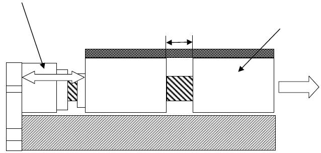
60 7. Setting the Home Position 7.1 Home Return Home return involves the operation explained below: [1] When a home return command is issued, the actuator moves in the direction set by the parameter for moving direction. [2] The software senses the mechanical end in the return operation. [3] The slider reverses its direction when this end is reached, after which the position where the Z-phase signal is detected becomes the reference point. [4] The slider travels further by the offset amount set by the parameter, and this position becomes home. 7.2 Fine-tuning the Home Position 7. Setting the Home Position The number of motor revolutions from the time the slider hits the stopper until the Z-phase signal is generated has been adjusted before the actuator is shipped. The standard value of the reversing distance when the slider hits the stopper, reverses its direction, and then stops at the home position, is shown in the table below. Model name Distance from mechanical stopper to home (approx. in mm) IS/ISP/ISA/ISPA-S 4 IS/ISP/ISA/ISPA-M, L 5 IS/ISP/ISA-W, ISPA-W 7 ISA/ISPA-M, L with intermediate support 5 IS/ISP/ISA/ISPA-W with intermediate support 15 As long as the home direction is the same, you can fine-tune the home position for each actuator by changing the parameter based on this value. Fine-tuning is made as follows: [1] Perform homing operation and confirm home. [2] Thereafter, the actuator moves to the desired home, after which the difference is checked. In the case of a XSEL or SSEL controller, the parameter for home preset is corrected accordingly. In the case of a SCON, MSCON controller, the parameter for home reset offset is corrected accordingly. Specifically, add or subtract the difference to/from the value currently current. [3] If you allow for a large offset, the movement range is limited by the amount of offset. If the offset is greater than 1 mm, you must also adjust the stroke soft limits. 7.3 Changing the Home Direction If the home direction is changed after the actuator has been delivered, the home direction parameter must be changed, and the encoder s Z-phase may also need to be adjusted on some models. Contact IAI. 52

61 7. Setting the Home Position 53
62 8. Options 54
63 8. Options 55
64 8. Options 56
65 8. Options 57
 [1] Reduced noise There is no longer metal noise generated by colliding balls and thus noise is reduced.")
66 8.7 Guide with Ball Retention Mechanism (Structure) A spacer (retainer) is inserted between adjacent balls (steel balls) in the guide to reduce noise and achieve smooth operation. This specification is indicated by RT in the model number. Ball 8. Options (Features) [1] Reduced noise There is no longer metal noise generated by colliding balls and thus noise is reduced. Since balls are aligned by retainers, annoying noise decreases. Ball Spacer (retainer) [2] Smooth operation Wear caused by friction between balls decreases, oil no longer runs out due to contact, and lubricating oil collects at the retainers. Accordingly, operation becomes smooth. 8.8 Metal Connector Specification With the metal connector specification, the actuator connectors are not made of plastics, but of metal. This specification is indicated by EU in the model number. 8.9 Double-slider Specification The double-slider specification means there are two, or double, sliders. The applicable model code is W. 58
67 9. Motor/Encoder Cables 9.1 Standard The same cables are used regardless of the actuator model. The applicable cables vary depending on the combined controller. Correspondence table of controllers and motor/encoder cables Controller XSEL-J/K XSEL-P/Q/R/S SSEL SCON, MSCON LS Without LS With LS Without LS With LS Without LS With LS Without LS With LS Applicable cables [1], [2] [1], [2], [3] [1], [4] [1], [5] [1], [4] [1], [5] [1], [4] [1], [5] [1] Motor cable CB-X-MA (Front vies) Controller end [2] Encoder cable CB-X-PA (Front vies) (Front vies) Actuator end (Front vies) * indicates the cable length (L). Up to 30 m can be specified. Example) 080 = 8 m [Minimum bending radius] Movable: 51 mm Fixed: 34 mm Wiring Color Signal Signal Color Wiring Green Red White Black Green Red White Black * indicates the cable length (L). Up to 30 m can be specified. Example) 080 = 8 m [Minimum bending radius] Movable: 44 mm Fixed: 29 mm 9. Motor/Encoder Cables Controller end Actuator end Wiring Color Signal 0.15 sq Blue (crimped) Orange Black Yellow Green Brown Gray Red The shield is clamped to the hood. Ground wire and braided shield wires Signal Color Wiring Black Yellow Blue Orange 0.15 sq Green (crimped) Brown Ground Gray Red 59
68 [3] Limit switch cable CB-X-LC (Front vies) Controller end [4] Encoder cable CB-X1-PA (Front vies) Actuator end * indicates the cable length (L). Up to 30 m can be specified. Example) 080 = 8 m [Minimum bending radius] Movable: 33 mm Fixed: 22 mm Wiring Color Signal Signal Color Wiring Skyblue Skyblue Pink Light green Pink Light green Orange Gray 1B/skyblue Note) 1B indicates one black dot mark. Orange Gray 1B/skyblue * indicates the cable length (L). Up to 30 m can be specified. Example) 080 = 8 m [Minimum bending radius] Movable: 44 mm Fixed: 29 mm 9. Motor/Encoder Cables (Front vies) Controller end Plug housing: XMP-09V (JST) Socket contact: BXA 001T-P0.6 (JST) x 9 Retainer: XMS-09V (JST) Note 6: Use the crimper recommended by the connector manufacturer. (Front vies) Actuator end Wiring Color Signal AWG26 (soldered) Orange Green Purple Gray Red Black Blue Yellow The shield is clamped to the hood. Ground wire and braided shield wires Signal Color Wiring Black Yellow Blue Orange AWG26 Green (crimped) Brown Ground Gray Red [5] Encoder cable with LS CB-X1-PLA L 14 LS end * indicates the cable length (L). Up to 30 m can be specified. Example) 080 = 8 m [Minimum bending radius] Movable: 54 mm Fixed: 36 mm (Front vies) Controller end Actuator end (Front vies) Wiring Color Signal White/blue White/yellow White/red White/black White/purple White/gray E24V 0V LS CLEEP OT RSV No No Signal Color Wiring E24V 0V White/blue White/yellow LS White/red AWG26 CLEEP White/black (soldered) OT RSV White/purple White/gray AWG26 (soldered) Orange Green Purple Gray Red Black Blue Yellow A+ A B+ B Z+ Z SRD+ SRD BKR BKR+ The shield is clamped to the hood No. Signal Color Wiring 1 Purple 2 Gray 3 Orange 4 Green AWG Red Black (soldered) 7 Ground 8 9 Blue Yellow (As for wire color, White/blue indicates that Ground wire and braided shield wires the band is white and insulator is blue. 60
69 9.2 Metal Connector Specification (Option Indicated by EU in Model Number) The same cables are used regardless of the actuator model. The applicable cables vary depending on whether or not LSs are used. Correspondence table of controllers and motor/encoder cables Controller XSEL-P/Q/R/S, SSEL, SCON, MSCON LS Without LS With LS Applicable cables [1], [2] [1], [3] [1] Motor cable CB-XEU-MA * indicates the cable length (L). Up to 30 m can be specified. Example) 080 = 8 m [Minimum bending radius] Movable: 48 mm Fixed: 48 mm Wiring Color Signal Signal Color Wiring Green Red White Black Green Red White Black 0.15 sq (crimped) [2] Encoder cable CB-XEU1-PA * indicates the cable length (L). Up to 30 m can be specified. Example) 080 = 8 m [Minimum bending radius] Movable: 44 mm Fixed: 29 mm Wiring Color Signal 9. Motor/Encoder Cables AWG26 (soldered) Signal Color Wiring Orange Green Orange Green Purple Gray Red Black Blue Yellow The shield is clamped to the hood. AWG26 (soldered) Red Black Purple Gray Blue Yellow The shield is connected to the earth sleeve. Ground wire and braided shield wires (As for wire color, White/blue indicates that the band is white and insulator is blue. 61
70 [3] Encoder cable with LS CB-XEU1-PLA * indicates the cable length (L). Up to 30 m can be specified. Example) 080 = 8 m [Minimum bending radius] Movable: 58 mm Fixed: 38 mm Signal Color Wiring Wiring Color Signal White/blue White/yellow White/blue White/yellow White/red White/black White/red AWG26 White/black (crimped) White/purple White/gray White/purple White/gray Signal Color Wiring Orange AWG26 (soldered) Green AWG26 (crimped) Green Purple Gray Red Black Red Black Purple Gray 9. Motor/Encoder Cables Blue Yellow Blue Yellow The shield is clamped to the hood. The shield is connected to the earth sleeve. Ground wire and braided shield wires (As for wire color, White/blue indicates that the band is white and insulator is blue. 62
71 10. Maintenance/Inspection (Note) Replacement of the brake is basically held at our site. Please contact us when a replacement of the brake is required Inspection Items and Intervals Perform maintenance/inspection according to the following timetable. The operating time is assumed to be 8 hours a day. If the actuator is used continuously for 24 hours or the utilization rate is otherwise high, shorten the inspection intervals accordingly. Visual inspection of Period machine exterior At start of operation After 1 month of operation After 3 month of operation After 3 month of operation thereafter (Note 2) After 6 month of operation Interior check Grease Supply (Note 1) Period of Grease Supply (reference) (Note 2) Every 6 months thereafter (Note 1) When the actuator is moved back and forth continuously over a distance of 30 mm or less, grease film may disappear. As a guide, move the actuator back and forth over a distance of 50 mm or more for five cycles or so after every 5,000 to 10,000 back-and-forth operations over a short distance. This will restore the oil film. (Note 2) Check the condition of grease and wipe it off in case it is extremely dirty before supplying new grease. [Period of Grease Supply (reference)] Supply grease in the earlier timing of either the operation distance or months described in the table below. Max. Velocity of Use [mm/s] Period of Grease Supply (reference) Operation Distance Months 0 to 750 or less 1,250 km 750 to 1500 or less 2,500 km 12 months 1500 to 2400 or less 5,000 km Caution: The grease may be degraded if the actuator has got stored for 6 months or more. Supply grease before starting to use. [Reference to 10.6 Grease Supply] The speed of grease degradation differs depending on the environment of use (temperature, humidity and ambient environment). It is recommended to shorten the period of grease supply in case of use in bad environment with high temperature, high humidity, high rate of dust and so on. Also, it is recommended to improve the environment in case the color of the grease changes remarkably due to bad environmental condition. 10. Maintenance/Inspection 10.2 Visual Inspection of the Machine Exterior Check the following items visually. Main body Cables General Loose mounting bolts Damage to cables, connection of connectors Noise, vibration 63
72 10.3 External Cleaning Clean the exterior surfaces from time to time. Wipe off dirt with a soft cloth. Depending on the situation, base oil of grease may ooze out to the actuator surface. If oil has oozed out, wipe it off using a soft cloth, etc. Do not spray compressed air on the actuator that might force dust into the crevices. Do not use petroleum-based solvents as they damage plastic parts and painted surfaces. If the unit gets badly soiled, moisten a soft cloth with a neutral detergent or alcohol and wipe the soiled area gently Interior Check Turn off the power, remove the screw cover and visually inspect the interior. For the interior inspection, check the following items. Actuator Loosening of actuator mounting bolts, etc. Guide Lubrication condition, soiling Ball screw Lubrication condition, soiling 10. Maintenance/Inspection Visually check the condition of the interior. Specifically, see if there is any dust or foreign object inside the actuator and also check the condition of lubrication. Even if the grease has turned brown, lubrication is fine as long as the traveling surface appears shiny. If the grease becomes dirty and dull due to dust, or if the grease has worn away due to an extended operating time, lubricate the parts after cleaning them. The procedure for checking the interior is explained below. [1] Remove the screw cover using an Allen wrench of 1.5 mm across flats for a small type, or 2 mm across flats for a medium or large type. With a large type, use an Allen wrench of 2.5 mm across flats to remove the screw cover. Do not remove the front cover since it supports the ball screw. Do not remove the motor cover since precision instruments are housed inside. [2] Check the interior. [3] When the inspection/maintenance is complete, tighten the mounting screws for the screw cover. The tightening torque is 10.3 N cm for a small type, 21.1 N cm for a medium type, or 43.1 N cm for a large type. Warning: Do not disassemble the front cover because the ball screw is supported by the front cover. If a proper adjustment of the front cover is lost, the shaft center may become offset and the traveling resistance may increase or life of each part may become shorter, or abnormal noises may generate. An encoder is built into the encoder cover. The encoder not only detects the rotation angle and home signal, but it also performs a critical function in the AC control and the encoder and motor phases have been adjusted precisely. Never touch the encoder. 64
73 10.5 Cleaning the Interior Wipe off dirt with a soft cloth. If constituents of grease have separated and base oil has accumulated on both ends of the guide rail, wipe off the oil using a soft cloth, etc. If the accumulated oil is not wiped off, it may seep out to the exterior of the actuator. Do not spray compressed air on the actuator that might force dust into the crevices. Do not use petroleum-based solvents, neutral detergents or alcohol. Caution: If grease contains a large amount of foreign matter, be sure to wipe off the dirty grease before adding new grease Grease supply Applicable Grease The following blends of grease are charged before shipment (except for custom-order models). In addition to the factory-charged grease blends, you can also use corresponding products available from each company. For details, inform the names of factor-set grease blends to each manufacturer and request selecting corresponding products. Location Factor-set grease Corresponding products Name Manufacturer Name Manufacturer Guide Daphne Eponex Albania Grease S2 Showa Shell Sekiyu Idemitsu Kosan Grease No. 2 UNIREX N2 Mobil Sekiyu Ball screw Multemp LRL No. 3 Kyodo Yushi Intermediate support Multemp LRL No. 3 Kyodo Yushi Warning: Never use fluorine grease. If fluorine grease is mixed with lithium grease, not only the performance of grease will be affected, but the actuator may also be damaged depending on the condition. 10. Maintenance/Inspection 65
74 Grease Supply (1) Grease supply to the ISA/ISPA/IS/ISP guide How to remove the screw cover and add grease A grease nipple is provided on the slider. [1] Remove the screw cover. (Use an Allen wrench of 1.5 mm across flats for a small type, or 2 mm across flats for a medium or large type.) [2] Squirt the grease in from one grease nipple using a grease gun. (See the figure below for the positions of grease nipples.) Model S M L L Grease Supply (reference) 1 cc to 1.5 cc 2 cc to 2.5 cc 3 cc to 3.5 cc 1.5 cc to 2 cc [3] Rotate the slider several times manually to spread out the grease evenly. Confirm that the ball tracks on the ball screw and guide look glossy with oil of grease. Supply grease again if it is not spread enough. [4] Wipe off any excess grease. 10. Maintenance/Inspection Caution: Charging too much grease may increase the agitation resistance and cause the ball screw to generate heat easily or allow excess grease on the ball screw to scatter around and dirty the surroundings as the screw turns. Be sure to wipe off excess grease. It is difficult to move actuators of short leads by hand. With these actuators, do not try to move the acuter by force, but connect a controller and move the actuator by jog operation. In case the grease got into your eye, immediately go see the doctor to get appropriate care. After finishing the grease supply work, wash your hands carefully with water and soap to rinse the grease off. Grease nipple (Note) Follow the grease nipple diameter shown in the list below when preparing a grease gun. Model Nipple diameter (mm) IS (P) A-S 3.5 IS (P) A-M 6.0 IS (P) A-L 6.0 Recommend grease gun Nozzle Maker MG70 N type THK 66
![(2) Adding grease to the ISA-W/ISPA-W/ISP-W guide Remove the screw cover to access two grease nipples, one each on the left and right of the slider. [1] Use an Allen wrench of 2.](/docs-images/77/76266344/images/75-2.jpg "5 mm across flats to remove the screws affixing the screw cover. [2] Add grease from the grease nipples on the end faces of the slider (refer to the drawing below). Grease Supply (reference) 3.")
75 (2) Adding grease to the ISA-W/ISPA-W/ISP-W guide Remove the screw cover to access two grease nipples, one each on the left and right of the slider. [1] Use an Allen wrench of 2.5 mm across flats to remove the screws affixing the screw cover. [2] Add grease from the grease nipples on the end faces of the slider (refer to the drawing below). Grease Supply (reference) 3.5 cc to 4 cc [3] Rotate the slider several times manually to spread out the grease evenly. Confirm that the ball tracks on the ball screw and guide look glossy with oil of grease. Supply grease again if it is not spread enough. [4] Wipe off any excess grease. Gease nipple (Note) Follow the grease nipple diameter shown in the list below when preparing a grease gun. Model Nipple diameter (mm) IS (P) A-W 6.6 Recommend grease gun Nozzle Maker MG70 H type THK (3) Adding grease to the ball screw Remove the screw cover and add grease. After cleaning the screw, apply grease using a finger and then move the slider back and forth to let the grease spread evenly. Finally, wipe off excess grease that has overflowed from the nut. Caution: Charging too much grease may increase the agitation resistance and cause the ball screw to generate heat easily or allow excess grease on the ball screw to scatter around and dirty the surroundings as the screw turns. Be sure to wipe off excess grease. It is difficult to move actuators of short leads by hand. With these actuators, do not try to move the actuator by force, but connect a controller and move the actuator by jog operation. In case the grease got into your eye, immediately go to see the doctor to get an appropriate care. After finishing the grease supply work, wash your hands carefully with water and soap to rinse the grease off. 10. Maintenance/Inspection (4) Adding grease to the intermediate support Applicable models: IS (P) (A)-MXMX, IS (P) (A)-LXMX, IS (P) (A)-LXUWX, IS (P) (A)-WXMX [Connecting rods] After cleaning the two connecting rods at the intermediate support, apply grease to the rods using a finger. Thereafter, move the slider back and forth to let the grease spread evenly. Connecting rod 67
![[Support bushes] After cleaning the support bushes at both ends of the intermediate support, apply grease to the areas around the bushes using a finger while turning each support bush.](/docs-images/77/76266344/images/76-1.jpg "Thereafter, move the slider back and forth to let the grease spread evenly.")
![Support bush [Top of slider and intermediate support] After cleaning the top of the slider and top of the intermediate support at both ends, apply grease to these areas using a finger.](/docs-images/77/76266344/images/76-2.jpg "This is to protect the top of the slider and intermediate support against contact with the screw cover. 10.")
76 [Support bushes] After cleaning the support bushes at both ends of the intermediate support, apply grease to the areas around the bushes using a finger while turning each support bush. Thereafter, move the slider back and forth to let the grease spread evenly. Support bush [Top of slider and intermediate support] After cleaning the top of the slider and top of the intermediate support at both ends, apply grease to these areas using a finger. This is to protect the top of the slider and intermediate support against contact with the screw cover. 10. Maintenance/Inspection Top of slider Top of intermediate support Caution: In case the grease got into your eye, immediately go to see the doctor to get an appropriate care. After finishing the grease supply work, wash your hands carefully with water and soap to rinse the grease off. 68
77 11. Motor Replacement Procedures 69
78 11. Motor Replacement Procedures 70

79 11. Motor Replacement Procedures 71

80 11. Motor Replacement Procedures 72

81 11. Motor Replacement Procedures 73


82 11. Motor Replacement Procedures 74

83 11. Motor Replacement Procedures 75

84 11. Motor Replacement Procedures 76

85 11. Motor Replacement Procedures 77

86 11. Motor Replacement Procedures 78


87 11. Motor Replacement Procedures 79

88 11. Motor Replacement Procedures 80
89 11. Motor Replacement Procedures 81
90 11. Motor Replacement Procedures 82


91 11. Motor Replacement Procedures 83

92 11. Motor Replacement Procedures 84
 Reconnect the motor cable and encoder cable connectors provided with the motor cover")
 Bolt the ground line to the motor bracket as it was previously secured.")

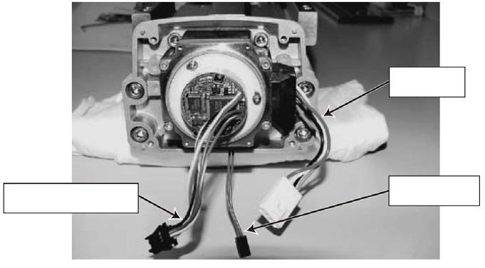
93 Assembling the Motor Cover (1) Reconnect the motor cable and encoder cable connectors provided with the motor cover to the motor unit. For the brake type, twist the brake cables around the M cables. brake cables (2) Bolt the ground line to the motor bracket as it was previously secured. (3) Store the motor connector beneath the motor and the encoder connector on the left side of the motor, and put all the wire/cable lines where they were previously. 11. Motor Replacement Procedures The encoder connector should be stored in a space on the left side of the motor. * The brake connector should be stored in the same manner. The motor connector should be stored in a space beneath the motor. 85
 of the encoder, and")


94 Caution : The left side (where is circled below) of the encoder is a point that is weak in noise durability. Do not attempt to put the M cables and brake cables near the left side (where is circled below) of the encoder, and store the cables at the bottom of the motor. Putting the cables near the encoder may lead the encoder to cause an operational error. Encoder Weakness Point Encoder Weakness Point (4) Secure the motor cover in place. 11. Motor Replacement Procedures Caution 1: Caution 2: Be careful not to pinch wires between the main body and the cover. The motor cover is made of plastic. When securing the cover, be careful not to damage the cover by tightening the bolts too much. 86

 Install the screw cover in the manner it was previously installed.")
95 Installing the Screw Cover (1) Install the seat cover. [1] [2] If the original condition was pattern [1], change it to pattern [2]. Install the seat cover so that the coupling check window becomes visible. (2) Install the screw cover in the manner it was previously installed. Screw cover Thin head screw x 2 Thin head screw x Motor Replacement Procedures 87
96 Correcting for Position Deviation (1) Connect the motor cable and encoder cable and turn on the controller power. (2) Use the PC software or teaching pendant to perform homing and check the home position. Repeat homing several times to confirm that the actuator returns to the same position. (If the actuator is of absolute specification, perform an absolute reset.) (3) Check the amount of position deviation. The position may have changed slightly from where it was before the motor was replaced. Accordingly, select a desired position number that allows you to check the amount of deviation before and after the replacement, and then perform positioning to that position and measure the amount of deviation. (4) Reflect the deviation in the home preset parameter in the case of an X-SEL/SSEL controller, or in the home return offset parameter in the case of an SCON, MSCON controller. [For the setting method, refer to 11.3, How to Set the Home Preset and Home Return Offset. ] * If the two positions differ significantly (one ball screw revolution or more = lead or more) or if the actuator does not return to the same position when homing is repeated, install the motor unit again by following the procedure described in this manual. When the motor unit was installed, a wrong spacer size may have been used or the slider may have moved instead of remaining stationary at the mechanical end Operation Check after Replacing the Motor 11. Motor Replacement Procedures After replacing the motor, perform continuous operation to confirm absence of vibration or abnormal noise. 88


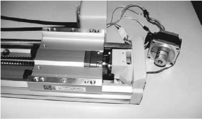
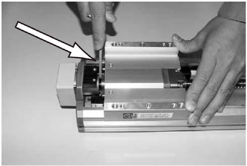
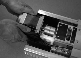
97 11.2 Replacing the Motor of the ISA-W/ISPA-W Series This manual details the procedure for replacement of an ISA-W/ISPA-W Series motor. When you need to replace your motor, please follow the steps described below. Because the screws and other components removed during replacement of the motor will be needed for reassembly, prepare a storage box in advance to keep those components so that you don t lose or misplace them. Caution: When replacing the motor, you must turn on/off the power and servo to perform the following tasks: [1] Position the coupling on the motor alone [2] Install the motor [3] Operate the brake Exercise due caution when carrying out each task with the power being supplied. The purpose of [1] and [2] is to correlate the motor/encoder and actuator positions. If these tasks are not performed, home return may not be implemented normally. [3] is performed because the brake, which is a non-excitation brake, cannot be released (= the slider cannot be moved) without excitation. (1) Remove the motor cover and rear cover. Use an Allen wrench of 2.5 mm across flats to remove the hexagonal socket head button bolts affixing the motor cover. Use an Allen wrench of 3 mm across flats to remove the hexagonal socket head bolts affixing the rear cover. 11. Motor Replacement Procedures Caution: Even when the motor cover does not come off easily, do not attempt to take it off forcefully with hand.it is because the anti-vibration rubber on the seat is stuck on the motor cover. Hit the cover with a tool such as a rubber hammer, which does not damage the cover or give excessive impact, to release the anti-vibration rubber from the cover before detaching the motor cover. Pulling the cover off forcefully with hand may cause injury with sharp edges, protruded parts or corners on the motor cover. 89


98 11. Motor Replacement Procedures 90

99 11. Motor Replacement Procedures 91

100 11. Motor Replacement Procedures 92


101 11. Motor Replacement Procedures 93


102 11. Motor Replacement Procedures 94
103 (15) Correcting the position deviation [1] Turn on the controller power. Next, use a PC software or teaching pendant to perform home return and confirm the home position. Repeat this several times to confirm that the actuator returns to the same home position every time. [2] Checking the position deviation The actuator may have moved slightly from the position assumed before replacing the motor. Accordingly, select any position number that lets you check the deviation between the positions before and after replacing the motor, and perform positioning to this position to measure the deviation. [3] Reflect the deviation in the home preset parameter in the case of an X-SEL/SSEL controller, or in the home return offset parameter in the case of an SCON, MSCON controller. [For the setting method, refer to 11.3, How to Set the Home Preset and Home Return Offset. ] * If the position is deviated significantly (by at least one rotation of the ball screw = at least the lead length), or if the actuator does not return to the same home position in each of the repeated home return operations, reinstall the motor according to the procedure explained herein. The slider may have been positioned at a wrong distance from the reference surface. (16) Operation check after replacing the motor After replacing the motor, perform continuous operation to confirm absence of vibration or abnormal noise. 11. Motor Replacement Procedures 95
 Open the position edit screen.")
104 11.3 How to Set the Home Preset and Home Return Offset Correct the position deviation by changing the parameter for home preset in the case of a XSEL or SSEL controller, or by changing the parameter for home return offset in the case of a SCON, MSCON controller. How to set these parameters is explained below XSEL and SSEL Controllers (1) Open the position edit screen. On the PC software screen, click, select a desired position number, and then click OK to display the following screen. Click this button to open the position edit screen. The current value is displayed. Position number 11. Motor Replacement Procedures (2) Compare the current value and the value achieved by positioning the actuator to the selected position number, and check the amount of deviation. [2] Click MV. [1] Select the position to move the actuator to. 96

105 11. Motor Replacement Procedures 97


106 11. Motor Replacement Procedures 98


107 ECON and SCON, MSCON Controllers (1) Open the position edit screen. On the PC software screen, click the following screen., select a desired position number, and then click OK to display Click this button to open the position edit screen. The current value is displayed. Point number (2) Compare the current value and the value achieved by positioning the actuator to the selected position number. [1] Select the position. [2] Click this button to make a step movement. 11. Motor Replacement Procedures 99
108 11. Motor Replacement Procedures 100


109 11. Motor Replacement Procedures 101

110 11. Motor Replacement Procedures 102

111 11. Motor Replacement Procedures 103
112 12. Appendix * The brake-equipped type is longer in 25.5mm and heavier in 0.3kg. 104
113 12. Appendix * The brake-equipped type is longer in 25.5mm and heavier in 0.3kg. 105
114 12. Appendix * The brake-equipped type is longer in 27mm and heavier in 0.5kg. 106
115 12. Appendix 107
116 2-8H7, reamed, depth 10 (tolerance for reamed hole pitch 0.02 mm) 12. Appendix * The brake-equipped type is longer in 27mm and heavier in 0.5kg. 108
117 12. Appendix * The brake-equipped type is longer in 27mm and heavier in 0.5kg. 109
118 2-8H7, reamed, depth 10 (tolerance for reamed hole pitch 0.02 mm) 12. Appendix * The brake-equipped type is longer in 27mm and heavier in 0.5kg. 110
119 12. Appendix * The brake-equipped type is longer in 27mm and heavier in 0.5kg. 111
120 H-9 drill counterbores, 16 counterbores, depth Appendix * The brake-equipped type is longer in 27mm and heavier in 0.5kg. 112
121 2-8H7, reamed, depth 10 (tolerance for reamed hole pitch 0.02 mm) 12. Appendix * The brake-equipped type is longer in 27mm and heavier in 0.5kg. 113
122 2-8H7, reamed, depth 10 (tolerance for reamed hole pitch 0.02 mm) 12. Appendix * The brake-equipped type is longer in 27mm and heavier in 0.5kg. 114
123 ISA-MZM-100, ISPA-MZM H7, reamed, depth 10 (tolerance for reamed hole pitch 0.02 mm) 4-M6, depth 20 4-M8, depth 20 Cable joint connector *1 2-M3, depth 6 (same on the opposite side) Home A At least 100 or more 12-M8, depth H7, reamed Reference surface Detail view of A Dimension and Mass by Stroke Detail view of T-slot at G base SE: Stroke end ME: Mechanical end 12. Appendix Stroke Weight (kg) Stroke Weight (kg) If the stroke is 700 or longer, use the base of the MXM type. For the installation dimensions, refer to the drawing on p
124 ISA-MZM-200, ISPA-MZM H7, reamed, depth 10 (tolerance for reamed hole pitch 0.02 mm) 4-M6, depth 20 4-M8, depth 20 Cable joint connector *1 2-M3, depth 6 (same on the opposite side) Home A At least 100 or more 12-M8, depth H7, reamed 12. Appendix Reference surface Detail view of A Dimension and Mass by Stroke Detail view of T-slot at G base SE: Stroke end ME: Mechanical end Stroke Mass (kg) Stroke Mass (kg) If the stroke is 700 or longer, use the base of the MXM type. For the installation dimensions, refer to the drawing on p
125 * The brake-equipped type is longer in 27mm and heavier in 0.8kg. 12. Appendix 117
126 12. Appendix * The brake-equipped type is longer in 27mm and heavier in 0.8kg. 118
127 12. Appendix * The brake-equipped type is longer in 27mm and heavier in 0.8kg. 119
128 12. Appendix * The brake-equipped type is longer in 27mm and heavier in 0.8kg. 120
129 12. Appendix * The brake-equipped type is longer in 27mm and heavier in 0.8kg. 121
130 12. Appendix * The brake-equipped type is longer in 27mm and heavier in 0.8kg. 122
131 12. Appendix * The brake-equipped type is longer in 27mm and heavier in 0.8kg. 123
132 12. Appendix * The brake-equipped type is longer in 27mm and heavier in 0.8kg. 124
133 12. Appendix * The brake-equipped type is longer in 27mm and heavier in 0.8kg. 125
134 12. Appendix * The brake-equipped type is longer in 27mm and heavier in 0.8kg. 126
135 ISA-LZM-200, ISPA-LZM H7, reamed, depth 10 (tolerance for reamed hole pitch 0.02 mm) 8-M8, depth 20 Cable joint connector *1 2-M3, depth 6 (same on the opposite side) Home At least 100 or more 4-8H7, reamed 12-M8, depth 20 SE: Stroke end ME: Mechanical end Reference surface A 12. Appendix Detail view of A Detail view of T-slot at E base Dimension and Mass by Stroke Stroke Mass (kg) Stroke Mass (kg) If the stroke is 700 or longer, use the base of the LXM type. For the installation dimensions, refer to the drawing on p
136 ISA-LZM-400, ISPA-LZM M8, depth H7, reamed, depth 10 (tolerance for reamed hole pitch 0.02 mm) Cable joint connector *1 2-M3, depth 6 (same on the opposite side) Home 4-8H7, reamed At least 100 or more 12-M8, depth 20 SE: Stroke end ME: Mechanical end 12. Appendix A Reference surface Detail view of A Detail view of T-slot at E base Dimension and Mass by Stroke Stroke Mass (kg) Stroke Mass (kg) If the stroke is 700 or longer, use the base of the LXM type. For the installation dimensions, refer to the drawing on p
137 12. Appendix * The appearance diameters are the same if equipped with brake. The weight increases in 0.5kg 129
138 12. Appendix * The appearance diameters are the same if equipped with brake. The weight increases in 0.5kg 130
139 12. Appendix * The appearance diameters are the same if equipped with brake. The weight increases in 0.5kg 131
140 12. Appendix * The appearance diameters are the same if equipped with brake. The weight increases in 0.5kg 132

141 12. Appendix 133


142 12. Appendix 134
![(8) From the [Controller (C)] menu, select [Absolute Reset (A)].](/docs-images/77/76266344/images/143-1.jpg "(9) When a [Warning] dialog box is displayed, click the [OK] button.")
![(10) The [Abs. Encoder Reset] dialog box will be displayed.](/docs-images/77/76266344/images/143-2.jpg "Click hear and the axis number changes.")
 Clicking the [Encoder Rotation Data Reset 1] button")
143 (8) From the [Controller (C)] menu, select [Absolute Reset (A)]. (9) When a [Warning] dialog box is displayed, click the [OK] button. (10) The [Abs. Encoder Reset] dialog box will be displayed. Click hear and the axis number changes. Select an axis that requires an absolute reset. 12. Appendix (11) Clicking the [Encoder Rotation Data Reset 1] button will display a [Warning] dialog box. Click the [Yes] button. 135

144 12. Appendix 136
145 12. Appendix 137
146 12. Appendix 138
147 12. Appendix 139
 To make sure grease is applied to the guide, open the screw cover and add grease from the grease nipple.")
![(Note 2) With all models other than the ISA-W, ISPA-W and ISP-W, open the screw cover and add grease from the grease nipple. [1] Turn the power OFF.](/docs-images/77/76266344/images/148-2.jpg "Take an appropriate amount of grease on your finger, insert the finger from the space below the screw cover, and apply grease to the guide. Caution: Wear a finger cot when working.")
148 (2) How to add grease With the ISA-W, ISPA-W and ISP-W types, the guide can be greased according to the method explained below. (Note 1) To make sure grease is applied to the guide, open the screw cover and add grease from the grease nipple. (Note 2) With all models other than the ISA-W, ISPA-W and ISP-W, open the screw cover and add grease from the grease nipple. [1] Turn the power OFF. Take an appropriate amount of grease on your finger, insert the finger from the space below the screw cover, and apply grease to the guide. Caution: Wear a finger cot when working. Working with a bare hand may cut your finger on the edge. 12. Appendix Apply grease in the area of each guide as shown in the photograph below. (The photograph shows a condition after removing the screw cover.) Guide Guide [2] Move the slider back and forth several times to let the grease spread evenly. Caution: If grease is not applied properly, grease may run out and an overload error or other alarm may generate. In case the grease got into your eye, immediately go see the doctor to get appropriate care. After finishing the grease supply work, wash your hands carefully with water and soap to rinse the grease off. 140
149 12. Appendix 141
 To make sure grease is applied to the ball screw, open the screw cover and add grease from the grease nipple.")
![[1] Apply grease to the ball screw by spraying grease from the space below the screw cover. Apply grease in the area of the ball screw as shown in the photograph below.](/docs-images/77/76266344/images/150-2.jpg "(The photograph shows a condition after removing the screw cover.) 12. Appendix Ball screw (Note) Be careful not to apply too much grease to cause dripping.")
150 (2) How to add grease The ball screw can be greased according to the method explained below. (Note) To make sure grease is applied to the ball screw, open the screw cover and add grease from the grease nipple. [1] Apply grease to the ball screw by spraying grease from the space below the screw cover. Apply grease in the area of the ball screw as shown in the photograph below. (The photograph shows a condition after removing the screw cover.) 12. Appendix Ball screw (Note) Be careful not to apply too much grease to cause dripping. Do this in several steps by applying a small amount each time and checking if a sufficient amount has been applied. [2] Move the slider back and forth several times to let the grease spread evenly. Caution: In case the grease got into your eye, immediately go to see the doctor to get an appropriate care. After finishing the grease supply work, wash your hands carefully with water and soap to rinse the grease off. 142
IS Series Actuator Operating Manual
 IS Series Actuator Operating Manual IS ISP ISA ISPA Fifteenth Edition Please Read Before Use Thank you for purchasing our product. This Operation Manual describes all necessary info rmation to operate
ROBO Cylinder RCP6/RCP6S Actuator Table Type Instruction Manual Second edition IAI America, Inc.
 ROBO Cylinder RCP6/RCP6S Actuator Table Instruction Manual Second edition Motor Straight : Side-Mounted Motor : TA4C, TA6C, TA7C TA4R, TA6R, TA7R IAI America, Inc. Please Read Before Use Thank you for
ROBO Cylinder RCP6/RCP6S Actuator Rod Type Instruction Manual. Second edition
 ROBO Cylinder RCP6/RCP6S Actuator Rod Type Instruction Manual Second edition Motor Straight Type: Side-Mounted Motor Type: RA4C, RA6C, RA7C, RA8C RA4R, RA6R, RA7R, RA8R IAI America, Inc. Please Read Before
ROBO Cylinder RCP6/RCP6S Actuator Radial Cylinder Instruction Manual
 ROBO Cylinder RCP6/RCP6S Actuator Radial Cylinder Instruction Manual Second Edition Motor Straight Type: RRA4C, RRA6C, RRA7C, RRA8C Motor Reversing Type: RRA4R, RRA6R, RRA7R, RRA8R IAI Corporation Please
ROBO Cylinder RCP5/RCP5CR Actuators Slider Type Instruction Manual
 ROBO Cylinder RCP5/RCP5CR Actuators Slider Type Instruction Manual Seventh Edition Standard Type Motor Straight Type: RCP5-SA4C, SA6C, SA7C Standard Type Motor Reversing Type: RCP5-SA4R, SA6R, SA7R Cleanroom
ROBO Cylinder Arm Type RCA RCS2 Actuators Operation Manual
 ROBO Cylinder Arm Type RCA RCS2 Actuators Operation Manual Sixth Edition Arm Type: RCA Type: A4R, A5R, A6R RCS2 Type: A4R, A5R, A6R IAI America, Inc. Please Read Before Use Thank you for purchasing our
ROBO Cylinder RCS2/RCS2W Actuators Rod Type. Operation Manual
 ROBO Cylinder RCS2/RCS2W Actuators Rod Type Operation Manual Eleventh Edition Standard Type Motor Straight Type (Coupling Type): RA4C, RA5C, RGS4C, RGS5C, RGD4C, RGD5C Standard Type Motor Straight Type
ROBO Cylinder RCP2/RCP2W Actuator Rod Type
 ROBO Cylinder RCP2/RCP2W Actuator Rod Type Operation Manual Thirteenth Edition Standard types Motor straight types Motor reversing types RCP2- RA2C RA3C RA4C RA6C RA8C RA10C RGS4C RGS6C RGD3C RGD4C RGD6C
Single-axis Robot. ISB/SSPA Series. S, M sizes added to the SSPA Series
 Single-axis Robot I S C a s t IS/SSP Series S, M sizes added to the SSP Series w w w. i n t e l l i g e n t a c t u a t o r. c o m major revamp of the single-axis robot IS series with improvements all
ROBO Cylinder RCP2/RCP2W Actuator Rod Type
 ROBO Cylinder RCP2/RCP2W Actuator Rod Type Operation Manual Fourteenth Edition Standard types Motor straight types Motor reversing types RCP2- RA2C RA3C RA4C RA6C RA8C RA10C RGS4C RGS6C RGD3C RGD4C RGD6C
ISB/SSPA Series. Single-axis Robot.
 G IS/SSP Series Single-axis Robot www.intelligentactuator.de major revamp of the single-axis robot IS series with improvements all around - from preciseness, rigidity and payload capacity to speed and
Please Read Before Use
 Horizontal Articulated Robot IX Series Wall-Mounting Type, Arm Length 300/350 (Wall-Mounting) IX-TNN-3015H, IX-TNN-3515H Wall-Mounting Type, Arm Length 300/350 (Inverse) IX-UNN-3015H, IX-UNN-3515H Operation
LSAS-N10/N15. Introducing New, Quasi-Absolute Type. Linear Servo Actuator Quasi-Absolute Type LSAS-N15 LSAS-N10
 Linear Servo Actuator Quasi-Absolute Type LSAS-N0/N5 LSAS-N5 LSAS-N0 Introducing New, Quasi-Absolute Type w w w. i n t e l l i g e n t a c t u a t o r. c o m Introducing a New Type of Absolute Linear Servo
ROBO Cylinder Rod Type
 ROBO Cylinder Rod Type RCS4-RA4C/RA6C/RA7C/RA8C RA4R/RA6R/RA7R/RA8R Instruction Manual First Edition ME3771-1A Specifications Installation Connecting with the Controller Maintenance and Inspection External
RCS3-CT8C RCS3-CTZ5C. obo c y linde r. d e. High-Speed Slider Type. High-Speed Table Type
 GB High-Speed Slider High-Speed Table www.r obo c y linde r. d e Achieving the Max. Speed of 2500 mm/s and Max. Acceleration of.2 G (Instantaneous Max. Acceleration of 4.8 G) Improved High-speed Performance
RCS2-TCA5N 351 RCS2-TCA5N. RCS2 ROBO Cylinder TCA5N. I Encoder type I: Incremental speciication RCS2
 Slider RCS2-TC5N Model Speciication Items RCS2 Series * See page Pre-47 for details on the model descriptions. TC5N I Encoder type I: Incremental speciication Robo Cylinder, Table, Short-Length Compact
ROBO Cylinder RCP2W Actuator Slider, Dust-proof/Splash-proof Type Operating Manual
 ROBO Cylinder RCP2W Actuator Slider, Dustproof/Splashproof Type Operating Manual Seventh Edition RCP2WSA16C IAI America, Inc. Please Read Before Use Thank you for purchasing our product. This Operating
ROBO Cylinder RCP2 Actuator ROBO Rotary Type
 ROBO Cylinder RCP2 Actuator ROBO Rotary Type Small Type, 330-degree Rotation Specification [RTBS/RTCS Types] Small Type, Multi-rotation Specification [RTBSL/RTCSL Types] Medium Type, 330-degree Rotation
RCP5 Series ABSOLUTE. obo c y linde r. d e. RoboCylinder with Standard Battery-less Absolute Encoder
 GB RoboCylinder with Standard Battery-less Absolute Encoder RCP Series ABSOLUTE www.r obo c y linde r. d e Introducing the RCP series actuator with battery-less absolute encoder, realizing the convenience
ISA/ISPA. w w w. i n t e l l i g e n t a c t u a t o r. d e LINEAR AXIS. Integrated System & Integrated System Precision
 G LINER XIS IS/ISP Integrated System & Integrated System Precision w w w. i n t e l l i g e n t a c t u a t o r. d e V I S U L I N D E X Singlexis Robots Highprecision positioning systems with a linear
RCS2-RTC. Large Diameter Hollow Rotary.
 RCS2-RTC Large Diameter Hollow Rotary www.intelligentactuator.com SIGNIFICANT INCREASE IN ACCURACY/SPEED/TORQUE Adoption of the hollow structure provides a large diameter hollow rotary series with improved
Thin and Small ROBO Cylinder Mini Cylinder RCD Actuator Operation Manual
 Thin and Small ROBO Cylinder Mini Cylinder RCD Actuator Operation Manual Second Edition Rod Type RA1D, RA1DA IAI America, Inc. 1 Please Read Before Use Thank you for purchasing our product. This Operation
ROBO Cylinder RCS2 Actuator ROBO Rotary
 ROBO Cylinder RCS2 Actuator ROBO Rotary [RT6/RT6R/RT7R Types] Operating Manual First Edition IAI America, Inc. Safety Precautions (Please read before using the product.) Before installing, operating, maintaining
Horizontal Articulated Robot IX Series
 Horizontal Articulated Robot IX Series Ceiling-mount Type, Arm Length 500/600/700/800 IX-HNN50 /60 /70 /80 IX-INN50 /60 /70 /80 Operation Manual Second Edition Introduction Thank you for purchasing an
ISA-W ISPA-W Actuator
 ISA-W ISPA-W Actuator Operation Manual First Edition IAI America Inc. Safety Precautions (Please Read Before Use) Before installing, operating, maintaining or inspecting this product, peruse this operating
Direct Drive Motor.
 Direct Drive Motor DD www.intelligentactuator.com High Speed, High Payload, Easy to djust, Introducing a Direct Drive Motor chieving Features The Direct Drive Motor is a rotary actuator that directly drives
RCP4 Stopper Cylinder Operation Manual
 RCP4 Stopper Cylinder Operation Manual Fourth Edition ST4525E ST68E, ST615E IAI America, Inc. Thank you for purchasing our product. Please Read Before Use This Operation Manual describes all necessary
Space-saving installation Flexible motor mounting
 Space-saving installation Flexible motor mounting compatible!! Pulse train input compatible Automatic actuator recognition Addition of new controller compatible with pulse trains Enables current position
Direct Drive Motor. Instruction Manual
 Direct Drive Motor Instruction Manual Ninth Edition IAI Corporation Please Read Before Use Thank you for purchasing our product. This Instruction Manual describes all necessary information to operate
EZS. Motorized Linear Slides. Series. RoHS-Compliant
 RoHS-Compliant Motorized Linear Slides EZS Series AUDIN -, avenue de la malle - 5137 Saint Brice Courcelles - Tel : 3...1 - Fax : 3... - Web : http: www.audin.fr - Email : info@audin.fr RoHS-Compliant
Advanced "Positioning" is in your hand.
 AZ Series Equipped Motorized Linear Slides Motorized Cylinders EAC Series / AZ Series Equipped Motorized Linear Slides Motorized Cylinders EAC Series / Lineup Added Battery-free Absolute Sensor Equipped
for PowerCON SCARA MSEL-PCX/PGX Program Controllers PowerCON SCARAIXP Series Arm Length 180mm/250mm 550mm/650mm
 PowerCON SCARAIXP Series Program Controllers for PowerCON SCARA MSEL-PCX/PGX Series added Arm Length 18mm/25mm 55mm/65mm www.intelligentactuator.com Introducing Arm Lengths 18/25/55/65 Added in Cost-effective
240 g. 290 g. Electric Actuators Series LEPY/LEPS. Miniature Rod Type/Miniature Slide Table Type
 Electric Actuators Series / Miniature Rod Type/Miniature Slide Table Type RoHS Compact and lightweight Rod Type Series Weight 24 g 6-25 Maximum pushing force: 5 N Positioning repeatability:.5 mm Possible
240 g. 290 g. Compact and lightweight. Electric Actuators. Series LEPY/LEPS. Miniature Rod Type/Miniature Slide Table Type
 Electric ctuators Series LEPY/LEPS Miniature Rod Type/Miniature Slide Table Type Step Motor (Servo/2 VDC) and lightweight Rod Type Series LEPY Weight 2 g LEPY6-2 RoHS Maximum pushing force: N Positioning
240 g. 290 g. Compact and lightweight. Electric Actuators. LEPY/LEPS Series. Miniature Rod Type/Miniature Slide Table Type
 Electric Actuators LEPY/LEPS Series Miniature Rod Type/Miniature Slide Table Type Compact and lightweight Rod Type LEPY Series Weight 24 g LEPY6-25 3 mm 2.5 mm Slide Table Type LEPS Series Weight 29 g
ELECYLINDER. Battery-less Absolute Encoder No Battery, No Maintenance, No Homing, No Going Back to Incremental.
 EC Battery-less Absolute Encoder No Battery, No Maintenance, No Homing, No Going Back to Incremental. www.intelligentactuator.com Simple Simple Simple 555 Working Working Workingjust just just minutes
Environment Clean Room Specification
 Environment Clean Room Specification ISO Class 4 *1 (ISO14644-1) Built-in vacuum piping Possible to mount the main body without removing the external cover etc. Body-integrated linear guide specification
Hollow Rotary RCP6-RTFML.
 Hollow Rotary RCP6-RTFML www.intelligentactuator.com Slim and lightweight RCP6-RTFML Rotary with large-diameter hollow shaft of φ49, suitable for combined axes, is now available 1 f49 large-diameter hollow
Toothed belt axis ELGC-TB-KF. Operating instruction [ ]
![Toothed belt axis ELGC-TB-KF. Operating instruction [ ]](/thumbs/83/87984161.jpg "Toothed belt axis ELGC-TB-KF. Operating instruction [ ]") Toothed belt axis ELGC-TB-KF en Operating instruction 8068220 2017-02 [8068222] Original instructions Identification of hazards and instructions on how to prevent them: Danger Immediate dangers which can
Toothed belt axis ELGC-TB-KF en Operating instruction 8068220 2017-02 [8068222] Original instructions Identification of hazards and instructions on how to prevent them: Danger Immediate dangers which can
RoHS Directive-Compliant Motorized Linear Slides EZS Series for Clean Room Use. Features
 Motorized Actuators RoHS Directive-Compliant Series for Clean Room Use The Series for Clean Room Use is a product designed with the same level of function and performance as the Series but is ideal for
ROBO Cylinder Rotary Straight Motor Model 64mm Width 200V Servo Motor I N T P O. Notes on Selection. Deceleration Rated torque
 Slider RCS2 Cylinder RCS2-RT6 SA4D : Aluminum base SS4D : Steel base Cylinder Rotary Straight Model mm Width 200V Configuration: RCS2 RT6 I 60 18 L Series Encoder Deceleration Ratio Compatible Cable Length
LJ1H LEJS40 AC
 Low-profile/Low center of gravity Height dimension reduced by approx. 36% (Reduced by 32 mm) 9 Electric Actuator LEJ Series Slider Type/High Rigidity 58 (Former model) LJ1H2 3 5 1 LJ1H2 LEJS4 RoHS Series
IXP Series MSEL-PGX. tuator.d e. PowerCon SCARA Robot. PowerCon SCARA Program Controller. Arm Length 180mm/250mm 550mm/650mm
 GB PowerCon SCARA Robot PowerCon SCARA Program Controller IXP Series MSEL-PGX Series added Arm Length 18mm/25mm 55mm/65mm www.intelligentac tuator.d e Introducing Arm Lengths 18/25/55/65 Added in Cost-effective
Inner block. Grease nipple. Fig.1 Structure of LM Guide Actuator Model KR
 LM Guide ctuator Model LM Guide + all Screw = Integral-structure ctuator Stopper Housing all screw Inner block Grease nipple Outer rail earing (supported side) Housing Stopper Double-row ball circuit earing
Installation and Connection Manual
 Installation and Connection Manual E Controller Kawasaki Heavy Industries, Ltd. 90202-1204DEA Preface Preface This manual describes the installation and connection of Kawasaki Painting Robot KJ series.
Linear Guide Types of Motorized Linear Slides and Motorized Cylinders. SRS15WM 2 Blocks
 Linear Guide Types of Linear Slides and Cylinders The linear guides used on motorized linear slides and motorized cylinders are made by THK. The table below lists the products of linear guides used by
High Rigidity Radial Cylinder Type. Ball circulating type built-in linear guide has evolved into a 4-row guide! The era of built-in guides has begun.
 High Rigidity Radial Cylinder Ball circulating type built-in linear guide has evolved into a 4-row guide! The era of built-in guides has begun. EC-RR H EC-RR7 H Use 4-row guide. 1Point 2-row linear guide
Robo Cylinder RCP3/RCA2.
 Robo Cylinder RCP/RCA2 www.intelligentactuator.com The next generation of Robo Cylinder offers lower cost, simpler operation, and easier maintainenance than ever before. Power Cylinder With Guide We have
EZS Series Slider EZC Series Cylinder
 HL01203 EZS Series Slider EZC Series Cylinder INSTALLATION MANUAL ORIENTAL MOTOR CO., LTD. Notes to the User This product must be handled by qualified personnel with expert knowledge of electrical and
Type. Page 518. A support guide is designed to support workpieces with significant overhang.
 Environment Clean Room Specification ISO Class 4 *1 (ISO14644-1) Built-in vacuum piping Possible to mount the main body without removing the external cover etc. Body-integrated linear guide specification
Motorized Linear Actuators. EZS Series SPV Series EZC Series EZA Series PWA Series
 Motorized Linear Actuators EZS Series SPV Series EZC Series EZA Series PWA Series Advancing Positioning Applications Oriental Motor s Motorized Actuators Oriental Motor offers a broad lineup of motorized
Electric Actuator/Slider Type Motor Parallel Type
 INFORMATION Electric Actuator/Slider Type Motor Parallel Type RoHS Reduced in overall length Parallel Reduced dimension Reduced in height Reduced dimension Parallel In-line In-line Size Length reduction
ROBO Cylinder Rod type RCP2-RA8C/RA8R
 ROBO Cylinder Rod type RCP2-/ w w w. i n t e l l i g e n t a c t u a t o r. c o m RA8 (-mm wide) actuators have been added to the ROBO Cylinder RCP2 series, rod type, to expand the lineup.
Cartesian Robot ICSB/ICSPB.
 Cartesian Robot ICSB/ICSPB www.intelligentactuator.com The ICSA Series Cartesian Robots Have Been Totally Upgraded! The ICSB/ICSPB Cartesian robots are pre-configured units based on the seven 2-axis configurations
ISWA/ISPWA Dust-proof/ Splash-proof Type Actuator Operating Manual. Second Edition
 ISWA/ISPWA Dust-proof/ Splash-proof Type Actuator Operating Manual Second Edition Safety Precautions (Please read before using the product.) Before installing, operating, maintaining or inspecting this
ICSB/ICSPB. Cartesian Robot.
 Cartesian Robot ICSB/ICSPB www.intelligentactuator.com 001 Features The ICSA Series Cartesian Robots Have Been Totally Renewed! The ICSB/ICSPB Series Cartesian Robots selected the most frequently used
Hybrid Control System, Alpha Step
 B Hybrid Control System, Alpha Step Hybrid Control System B-1 Overview... B-2 Overview Hybrid Control System Battery-Free, Absolute Sensor Equipped AZ Series... B-16 Electric Linear Slides EZS Series AZ
STEPPING MOTOR SINGLE-AXIS ROBOTS
 Product ineup Series STEPPING MOTOR SINGE-XIS ROBOTS The newly developed vector control method delivers functions that are comparable to the performance of servomotors. Newly added space-saving models
Cartesian Robot ICSB/ICSPB.
 Cartesian Robot ICSB/ICSPB www.intelligentactuator.com The ICSA Series Cartesian Robots Have Been Totally Renewed! The ICSB/ICSPB Series Cartesian Robots selected the most frequently used seven 2-axis
SPV Series Slides OPERATING MANUAL. Table of contents 1 Introduction Compliance with the EC Directives Names of parts...
 HL-17012 SPV Series Slides OPERATING MANUAL Thank you for purchasing an Oriental Motor product. This Operating Manual describes product handling procedures. Please read this Operating Manual and the separate
Linear & Rotary Actuators F-41
 & F-41 & DRS Series Equipped Page Series Equipped F-4 F-41 F-4 Series Equipped $ $ For detailed information about regulations and standards, please see the Oriental Motor website. The Series is a line
Your motor and driver can be used together! Manufacturers of compatible motors: 8 companies. Ball screw drive. Series LEJS. Size
 Motorless Type Electric Actuators New RoHS Your motor and driver can be used together! Manufacturers of compatible motors: companies Mitsubishi Electric Corporation SANYO DENKI CO., LTD. Panasonic Corporation
Easy Slide Rails ov -easy_slide_divider - U pdated
 Easy Slide Rails ov-easy_slide_divider - Updated - 18-09-2017 163 Easy Slide Rails Easy Slide Rails Introduction The Easy Slide family of linear rails have a compact cross-section and low-friction movement.
Design & Selection. Installation & Adjustment
 U SM Series WRNING This product must not be used submerged in water, oil or powder, or where coolant, coolant fluid or swarf, etc., may come in contact. lways incorporate an interlock in the control circuit
Ball. Ball cage. Fig.1 Structure of Caged Ball LM Guide Actuator Model SKR
 Caged all LM Guide Actuator Model Inner block all screw shaft Grease nipple Outer rail all cage all Structure and Features Fig.1 Structure of Caged all LM Guide Actuator Model Caged all LM Guide Actuator
New IntelligentActuator Series ISB/SSPA
 Product Overview GB New IntelligentActuator Series ISB/SSPA Dust Protection IP30 ISO Cleanliness Class 4 1-axis position controller 1-2-axis program controller 1-4-axis program controller or high-performance
506E. LM Guide Actuator General Catalog
 LM Guide Actuator General Catalog A LM Guide Actuator General Catalog A Product Descriptions 506E Caged Ball LM Guide Actuator Model SKR.. A2-4 Structure and Features... A2-4 Caged Ball Technology... A2-6
Electric Actuators. New. Motorless Type. Series LE. Your motor and driver can be used together! Manufacturers of compatible motors: 8 companies
 Motorless Type Electric Actuators New RoHS Your motor and driver can be used together! Manufacturers of compatible motors: companies Mitsubishi Electric Corporation SANYO DENKI CO., LTD. Panasonic Corporation
T8 Torque Sensor Operation Manual
 T8 Torque Sensor Operation Manual Page 1 of 11 Imprint Valid for... Reprint Interdiction Modification Torque sensor type T8 Reprints, even in extracts, only with written authority. Technical changes reserved.
Development of Relief Valve Automatic assembly technology
 Development of Relief Valve Automatic assembly technology Technology Explanation Development of Relief Valve Automatic assembly technology TAKIGUCHI Masaki Abstract Construction machinery is equipped with
What is Robo Cylinder?
 RCS What is Robo Cylinder? Robo Cylinder is an electric actuator that employs ball screw, linear guide and AC Servo motor. Using the know-how obtained from manufacturing 150 thousand axis robots, while
CLOSED LOOP STEPPING MOTOR SINGLE-AXIS ROBOTS
 TRANSERVO Series Product Lineup CLOSED LOOP STEPPING MOTOR SINGLE-AXIS ROBOTS Excellent characteristics of both stepping motor and servomotor were combined. Stepping motor single-axis robots "TRANSERVO"
Linear Drive with Toothed Belt Series OSP-E..B. Contents Description Overview Technical Data Dimensions Order Instructions 46
 Linear Drive with Toothed Belt Contents Description Page Overview 35-38 Technical Data 39-43 Dimensions 44-45 Order Instructions 46 35 The System Concept ELECTRIC LINEAR DRIVE FOR POINT-TO-POINT APPLICATIONS
Caged Ball LM Guide Actuator SKR
 Caged Ball LM Guide Actuator SKR For details, visit THK at www.thk.com Product information is updated regularly on the THK website. CATALOG No.309-11E Integrated LM Guide and Ball Screw High-rigidity /
Vertical Linear Drive with Toothed Belt and Integrated Recirculating Ball Bearing Guide Series OSP-E..BV
 Vertical Linear Drive with and Integrated Recirculating Ball Bearing Guide Series OSP-E..BV Overview...25-28 Technical Data...29-31 Dimensions...32-33 25 Features TOOTHED BELT DRIVE FOR VERTICAL MOVEMENTS
OPERATING MANUAL. High-efficiency AR Series. Stepping motor and driver package. Introduction. Applicable motor. Before use
 HM-08 OPERATING MANUAL Stepping motor and driver package High-efficiency AR Series DC power input Built-in Controller Type (RS-8 communication function) Driver Introduction Before use Only qualified personnel
Spindle axis ELGC-BS-KF. Operating instructions [ ]
![Spindle axis ELGC-BS-KF. Operating instructions [ ]](/thumbs/87/97202885.jpg "Spindle axis ELGC-BS-KF. Operating instructions [ ]") Spindle axis ELGC-BS-KF en Operating instructions 8067243 2017-01 [8067245] Original instructions Identification of hazards and instructions on how to prevent them: Danger Immediate dangers which can lead
Spindle axis ELGC-BS-KF en Operating instructions 8067243 2017-01 [8067245] Original instructions Identification of hazards and instructions on how to prevent them: Danger Immediate dangers which can lead
CLEAN ROBOTS CLEAN. Type
 LEN Type Product Lineup LEN ROOTS Suitable for electronics component, food, and medical unit related work in clean room. High sealing structure, dust generation prevention, and improvement of suction efficiency
TORQUE TRANSDUCER TMHFB-*NM (for Torque Transducer) Instruction Manual. MinebeaMitsumi Inc. Sensing Device Business Unit
 Instruction Manual. MinebeaMitsumi Inc. Sensing Device Business Unit") TORQUE TRANSDUCER TMHFB-*NM (for Torque Transducer) Instruction Manual MinebeaMitsumi Inc. Sensing Device Business Unit Please read this manual thoroughly before attempting to use the equipment. Be sure
TORQUE TRANSDUCER TMHFB-*NM (for Torque Transducer) Instruction Manual MinebeaMitsumi Inc. Sensing Device Business Unit Please read this manual thoroughly before attempting to use the equipment. Be sure
NEW LM Actuator. US Only. Optimal for high speed and long stroke Long term maintenance-free operation is actualized Lightweight, compact structure
 NEW LM Actuator Optimal for high speed and long stroke Long term maintenance-free operation is actualized Lightweight, compact structure TY US Only CATALOG No.352E Structure of Model TY This belt drive
Maximizes on AC Servo capabilities.
 DS DS Dynamic Series Maximizes on AC Servo capabilities. Ultra compact, coupling-free design. (Example below: DS-SA4-) Easy to mount the main body. (Setting is possible without removing the cover) 42.5mm
Precision Cylinder. MTS Series. ø8, ø12, ø16, ø20, ø25, ø32, ø40 MXH MXS MXQ MXQ MXF MXW MXJ MXP MXY MTS D- -X. Series Variations MTS8
 Precision Cylinder Series, ø, ø6, ø, ø, ø, ø MXS Series Variations Model 8 Standard stroke (mm) 7 7 Rod end configuration Cushion Rubber bumper End lock Made to Order Rod Variable stroke/ through-hole
Stopping Accuracy of Brushless
 Stopping Accuracy of Brushless Features of the High Rigidity Type DGII Series Hollow Rotary Actuator The DGII Series hollow rotary actuator was developed for positioning applications such as rotating a
Cat. No. I194E-EN-03B. Washdown Delta Robot ZX-T Series. Delta Robot IP67 Mini Delta Robot IP67 INSTALLATION MANUAL
 Cat. No. I194E-EN-03B Washdown Delta Robot ZX-T Series R6Y3 Series Delta Robot IP67 Mini Delta Robot IP67 INSTALLATION MANUAL CONTENTS R6Y3 Installation Manual Safety Instructions 1. Safety Information
SCARA ROBOT. LS20 series MANIPULATOR MANUAL
 SCARA ROBOT LS20 series MANIPULATOR MANUAL Rev.5 EM183R3615F MANIPULATOR MANUAL LS20 series Rev.5 SCARA ROBOT LS20 series Manipulator Manual Rev.5 Copyright 2016-2018 SEIKO EPSON CORPORATION. All rights
SCARA ROBOT. G1 series MANIPULATOR MANUAL
 SCARA ROBOT G1 series MANIPULATOR MANUAL Rev.11 EM16XR3291F MANIPULATOR MANUAL G1 series Rev.11 SCARA ROBOT G1 series Manipulator Manual Rev.11 Copyright 2009-2016 SEIKO EPSON CORPORATION. All rights reserved.
RS3-55 series SCARA ROBOT MANIPULATOR MANUAL
 SCARA ROBOT RS3-55 series MANIPULATOR MANUAL Rev.1 EM108R2070F This manual describes the information on how to use RS3-55 series. For other information, refer to RS series manipulator manual. MANIPULATOR
INSTRUCTION MANUAL ELECTRIC ACTUATOR. ETS Series SM CKD Corporation
 SM-606904 INSTRUCTION MANUAL ELECTRIC ACTUATOR ETS Series Be sure to read this Instruction Manual thoroughly before operating the product. In particular, make sure to carefully read and understand all
...components in motion. Easy Rail
 ...components in motion Easy Rail Easy Rail Introduction The Easy Rail family have a compact cross-section and low-friction movement. Robust and Long Service Life Easy Rail s range of cross-sectional rail
DGII Series Actuator. Hollow Rotary Actuator OPERATING MANUAL
 HL-80002-7 Hollow Rotary Actuator DGII Series Actuator OPERATING MANUAL 1 Introduction... 2 2 Safety precautions... 8 3 Precautions for use... 11 4 Installation... 14 5 Connection... 25 6 Maintenance and
BLH. 24 VDC Input 15W / 30W / 50W / 100W BLH
 BLH 24 VDC Input 15W / 30W / 50W / 100W BLH BLH BLH BLH BLH 2 3 System Configuration Geared Type/Combination Type Parallel Shaft Gearhead/Round Shaft Type The system configuration shown above is an example.
BEFORE USING THE PRODUCT
 HL-17015-5 BEFORE USING THE PRODUCT Thank you for purchasing an Oriental Motor product. Please read this BEFORE USING THE PRODUCT and the separate manual entitled OPERATING MANUAL thoroughly to ensure
Standard specifications BA006NFE01
 Standard specifications BA006NFE01 1st Edition : ###### 2nd Edition : January 20, 2015 March 29, 2018 KAWASAKI HEAVY INDUSTRIES, LTD. ROBOT DIVISION Materials and specifications are subject to change without
Electric Rotary Table
 Electric Rotary Table Series LER RoHS H Step Motor (Servo/24 VDC) Low profile New Continuous Basic type [mm] rotation Model H specification LER1 42 LER3 53 LER5 68 High precision type [mm] Model H LERH1
TECHNICAL REFERENCE.
 TECHNICAL REFERENCE 7 www.intelligentactuator.com /Others /Others (IAI Products) -33 /Others Considerations when Switching from Air Cylinders -3 Allowable Moment -37 Operational Life -38 Caution when Using
Vertical Linear Drive with Toothed Belt and Integrated Recirculating Ball Bearing Guide Series OSP-E..BV
 Vertical Linear Drive with Toothed Belt and Integrated Recirculating Ball Bearing Guide Series OSP-E..BV Contents Description Page Overview 25-28 Technical Data 29-33 Dimensions 34 Order Instructions 35
Stepper Motors ver ver.5
 A Stepper s Stepper s A-1 Overview... A-2 Overview and... A-15 & Stepper and RK Series A-16 RK... A-47... A-51 Stepper Series A-52 Stepper Series A-8 See Full Product Details Online www.orientalmotor.com
240% 19% reduced. Compact Slide. MXH Series. Improved by up to. With new high rigidity linear guide. 369g. ø6, ø10, ø16, ø g.
 Compact Slide Series ø, ø, ø, ø RoHS Allowable moment MXS Improved by up to MXQ MXQ 2% MXF MXW MXJ MXP MXY With new high rigidity linear guide MTS Allowable moment improvement illustrated below Allowable
NEW Compact series. New KSF10 Size, Now Available Top Cover Type / Open Cover Type Lineup. For details, visit THK at Compact Series KSF
 NEW ompact series ompact Series New 1 Size, Now vailable Top over Type / Open over Type For details, visit THK at www.thk.com information is updated regularly on the THK website. TLOG No.396-1E-EU ELETRI
Stepping Motor and Driver Package. High-Efficiency AR Series. DC Power-Supply Input. Built-in Controller Type Pulse Input Type
 Stepping Motor Driver Package High-Efficiency R Series DC Power-Supply Input Built-in Type Type The extensive R Series DC Power-Supply Input lineup that utilizes high-efficiency technology. Two types are