Max. 30A 2 Coils Normal Open Contact Type. Positive Car : Ground, or. Max. 20A 2 Coils Normal Open Contact Type. Battery. Positive Car : Ground, or
|
|
|
- Dayna Fields
- 6 years ago
- Views:
Transcription


1 HEAD LIGHT RELAY SLR-12B W/FUSE, RED COVER Max. 30A 2 Coils Normal Open Contact Type B Battery S1, S2 Dimmer SW or Toggle SW L1, L2 Head Lamp or Fog & Driving Lamp S3 Positive Car : Ground, or Negative Car : Terminal B SLR-24B W/FUSE, RED COVER Max. 20A 2 Coils Normal Open Contact Type S1, S2 Dimmer SW or Toggle SW L1, L2 Head Lamp or Fog & Driving Lamp S3 Positive Car : Ground, or Negative Car : Terminal B SLR-12D W/O FUSE, BLUE COVER Max. 30A 2 Coils Normal Open Contact Type S1, S2 Dimmer SW or Toggle SW L1, L2 Head Lamp or Fog & Driving Lamp S3 Positive Car : Ground, or Negative Car : Terminal B SLR-24D W/O FUSE, BLUE COVER Max. 20A 2 Coils Normal Open Contact Type S1, S2 Dimmer SW or Toggle SW L1, L2 Head Lamp or Fog & Driving Lamp S3 Positive Car : Ground, or Negative Car : Terminal B 144
 Switch")
 Switch")


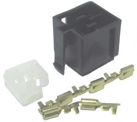
2 HEAVY DUTY RELAY SR05A-12 Break Max. 20A / Make Max. 40A through Switch Screw L1 Load 1 connection L2 Load 2 C1 (Round Male Plug Connection) Switch C2 (Round Female Plug Connection) Ground SR05A-24 Break Max. 15A / Make Max. 30A through Switch Screw L1 Load 1 connection L2 Load 2 C1 (Round Male Plug Connection) Switch C2 (Round Female Plug Connection) Ground SR04A-12C With Diode Break Max. 30A / Make Max. 60A W/Water proof skirt C1 Ground C2 Switch L1 Load of Break Side L2 Load of Make Side SR04A-24C With Diode Break Max. 25A / Make Max. 50A W/Water proof skirt C1 Ground C2 Switch L1 Load of Break Side L2 Load of Make Side SR04A-601 Connector Ass'y for SR04A-12C, SR04A-24C Relay Attachment Female Termainal ( x 3pcs.) ( x 2pcs.) 145


3 SUPER SMALL RELAY SRM-12 LIGHT YELLOW COVER Break Max. 20A / Make Max. 40A C1 Ground C2 Switch L1 Load of Break Side L2 Load of Make Side SRM-24 LIGHT YELLOW COVER Break Max. 15A / Make Max. 30A C1 Ground C2 Switch L1 Load of Break Side L2 Load of Make Side SRN-12 LIGHT YELLOW COVER Max. 40A for Universal C1 Ground C2 Switch L2 Load SRN-24 LIGHT YELLOW COVER Max. 30A for Universal C1 Ground C2 Switch L2 Load SRM Female Terminals Connector Ass'y for SRM, SRN Relay 146


4 SUPER SMALL RELAY SR01A-12B Break Max. 20A / Make Max. 40A ISO TYPE W/Water proof skirt 30 Battery 85 Ground 86 Switch 87 Load of Make Side 87a Load of Break Side SR01A-24B Break Max. 15A / Make Max. 30A ISO TYPE W/Water proof skirt 30 Battery 85 Ground 86 Switch 87 Load of Make Side 87a Load of Break Side SR01A-12C With Diode Break Max. 20A / Make Max. 40A ISO TYPE W/Water proof skirt 30 Battery 85 Ground 86 Switch 87 Load of Make Side 87a Load of Break Side SR01A-24C With Diode Break Max. 15A / Make Max. 30A ISO TYPE W/Water proof skirt 30 Battery 85 Ground 86 Switch 87 Load of Make Side 87a Load of Break Side SR Female Terminals Connector Ass'y for SR01A-12/24 Relay 147


5 SUPER SMALL RELAY SR02B-12 Max. 20A for Universal 3 Battery 1 Switch 2 Ground 5 Load SR02B-24 Max. 15A for Universal 3 Battery 1 Switch 2 Ground 5 Load MICRO RELAY SR07A-12 SR07A-12C W/DIODE Rated Current (Resistance Load) Break 10A Make 20A W/Water proof skirt 3 Battery 1 Switch 2 Ground 4 Load of Breake Side 5 Load of Make Side SR07A-24 SR07A-24C W/DIODE Rated Current (Resistance Load) Break 5A Make 10A W/Water proof skirt General W/Diode 3 Battery 1 Switch 2 Ground 4 Load of Breake Side 5 Load of Make Side SR07A-601 Attachment Connector General W/O Diode Connector 1ea.,Female Terminal big size 2pcs., small size 3pcs. 148
 S Switch (Red Lead Wire) L1 Load of Break Side (White Lead Wire) L2 Load of Make Side (Yellow Lead Wire) E Ground (Black Lead Wire) B")
 S Switch (Red Lead Wire) L1 Load of Break Side (White Lead Wire) L2 Load of Make Side (Yellow Lead Wire) E Ground (Black Lead Wire)")
 S Switch (Blue Lead Wire) L1 Load of Break Side (White Lead Wire) L2 Load of Make Side (Yellow Lead Wire) E Ground (Black Lead Wire) B")
6 ON / OFF DELAY TIMER RELAY TR01-12 ON DELAY TIMER On Delay Time : From 0.2 second to 6 second adjustable (Blue Lead Wire) S Switch (Red Lead Wire) L1 Load of Break Side (White Lead Wire) L2 Load of Make Side (Yellow Lead Wire) E Ground (Black Lead Wire) B L1 S L2 E TR01-24 ON DELAY TIMER On Delay Time : From 0.2 second to 6 second adjustable (Blue Lead Wire) S Switch (Red Lead Wire) L1 Load of Break Side (White Lead Wire) L2 Load of Make Side (Yellow Lead Wire) E Ground (Black Lead Wire) TR04-12 OFF DELAY TIMER Off Delay Time : From 0.1 second to 6 second adjustable (Red Lead Wire) S Switch (Blue Lead Wire) L1 Load of Break Side (White Lead Wire) L2 Load of Make Side (Yellow Lead Wire) E Ground (Black Lead Wire) B L1 (Note) Outside view will be changeable. TR04-24 OFF DELAY TIMER Off Delay Time : From 0.1 second to 6 second adjustable (Red Lead Wire) S Switch (Blue Lead Wire) L1 Load of Break Side (White Lead Wire) L2 Load of Make Side (Yellow Lead Wire) E Ground (Black Lead Wire) S L2 E (Note) Outside view will be changeable. SR WATERPROOF COVER For TR01-12 TR01-24 TR03-12 TR
 FR-24 Connection of Terminal L (Blue Wire : Male Terminal) To Lamp through Flasher Switch B (Red Wire : Male Terminal) To Main Switch through Fuse E (Black Wire : Spade type Terminal) To")
7 AZARD WARNING AND HEAVY DUTY FLASHER RELAY FR-24 Heavy Duty Transistor type Flasher Relay 25W W 13 +3W Hazard Warning Max. 430W ( 18A) FR-24 Connection of Terminal L (Blue Wire : Male Terminal) To Lamp through Flasher Switch B (Red Wire : Male Terminal) To Main Switch through Fuse E (Black Wire : Spade type Terminal) To Ground Note on Use 1. This relay is only for Minus Ground car and is used both as Hazard Warning and Flasher relay. 2. Make sure not to install this relay at outside of car. 3. Installation and removal of this relay should be done after turnoff of main switch. 4. When flashing unstableness and noise occur, change B (Red) wire for AV or AVS wire more than 2m m2 from place close to the battery. MINI BLADE FUSE HOLDER MFH-1 Double Connection Use is possible. 1Two AVS 2m m2 Red Wires are attached. 2Fuse(Max. 20A) is not installed. 3This holder is of waterproof. 4In case of double connection use, fix the Single Use holders to the real machine by vinyl band. Double Connection Use 150
8 STARTER RELAY SS080D Max. 120A (Within 30 seconds) 2 Holes Stay Type M (Screw Connection) Starter S (Red Wire Male Terminal) Starter Switch SS080DB Max. 120A (Within 30 seconds) 1 Hole Stay Type M (Screw Connection) Starter S (Red Wire Male Terminal) Starter Switch SS090 Max. 60A (Within 30 seconds) 2 Holes Stay Type M (Screw Connection) Starter S1 (White Stripe on Black Wire Male Term Switch S2 (Black Wire Female Terminal) Ground SS090B Max. 60A (Within 30 seconds) 1 Hole Stay Type M (Screw Connection) Starter S1 (White Stripe on Black Wire Male Term Switch S2 (Black Wire Female Terminal) Ground 151
9 STARTER RELAY SS150D Rated Current 80A (Continuous) 2 Holes Stay Type M (Screw Connection) Starter S (Red Wire Male Terminal) Starter Switch JIDECO NO. M2S SS150DB Rated Current 80A (Continuous) 1 Hole Stay Type M (Screw Connection) Starter S (Red Wire Male Terminal) Starter Switch SS160 Rated Current 50A (Continuous) 2 Holes Stay Type M (Screw Connection) Starter S1 (White Stripe on Black Wire Male Term Switch S2 (Black Wire Female Terminal) Ground JIDECO NO. MS SS160B Rated Current 50A (Continuous) 1 Hole Stay Type M (Screw Connection) Starter S1 (White Stripe on Black Wire Male Term Switch S2 (Black Wire Female Terminal) Ground 152
 Battery L (8m/mφScrew Connection) Load S1 (5m/mφScrew Connection) Switch S2 (5m/mφScrew Connection) Ground SS2139-24 Max.")
 Battery L (8m/mφScrew Connection) Load S1 (5m/mφScrew Connection) Switch S2 (5m/mφScrew Connection) Ground SS2143-48 48V Max.")
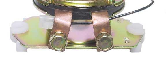
10 SOLENOID RELAY SS Max. 200A (Within 15 minutes) 1 Coil Normal Open Double Silver Contact Continuous working Heavy Duty Type for Battery Forklift, Golf Cart, Industrial Machine Etc. B (8m/mφScrew Connection) Battery L (8m/mφScrew Connection) Load S1 (5m/mφScrew Connection) Switch S2 (5m/mφScrew Connection) Ground SS Max. 100A (Within 15 minutes) 1 Coil Normal Open Double Silver Contact Continuous working Heavy Duty Type for Battery Forklift, Golf Cart, Industrial Machine Etc. B (8m/mφScrew Connection) Battery L (8m/mφScrew Connection) Load S1 (5m/mφScrew Connection) Switch S2 (5m/mφScrew Connection) Ground SS V Max. 50A (Within 15 minutes) 1 Coil Normal Open Double Silver Contact Continuous working Heavy Duty Type for Battery Forklift, Golf Cart, Industrial Machine Etc. B (8m/mφScrew Connection) Battery L (8m/mφScrew Connection) Load S1 (5m/mφScrew Connection) Switch S2 (5m/mφScrew Connection) Ground SS Max. 100A (Within 15 minutes) 1 Coil Normal Open Single Silver Contact Short Time working Heavy Duty Type for Battery Forklift, Golf Cart, Industrial Machine Etc. B (8m/mφScrew Connection) Battery L (8m/mφScrew Connection) Load S1 (5m/mφScrew Connection) Switch S2 (5m/mφScrew Connection) Ground 153


 POSITIVE CUT Voltage Drop : 8279-0052 /")
 POSITIVE CUT Voltage Drop : 3V Ref.")
11 BATTERY RELAY BS12-1A (4T) NEGATIVE CUT Voltage Drop : Less than 0.3V Ref. No. (BS-1) Industrial Machine BS12-4A (4T) POSITIVE CUT Voltage Drop : Less than 0.3V Ref. No (BS-431, -581) Industrial Machine BS24-1A (4T) NEGATIVE CUT Voltage Drop : Less than 0.3V Ref. No / 0018 / 0021 / 0033 / C0500 (BSE-1), (MSI-24), (BS412) Isuzu Bus, Truck, Nissan UD Diesel Truck BS24-4A (4T) POSITIVE CUT Voltage Drop : Less than 0.3V Ref. No / 0055 / 0065 (BS-H / Q / L) / Isuzu Bus, Truck Hino Truck BS24-5 (4T) POSITIVE CUT Voltage Drop : Less than 0.3V Ref. No Z0001, (BS-462) Nissan UD Diesel Truck 154

 POSITIVE CUT, W/DIODE Voltage")
")
 POSITIVE CUT Voltage")
 (0501-161-002 / With")
12 BATTERY RELAY BS24-5B (4T) POSITIVE CUT, W/DIODE Voltage Drop : Less than 0.3V Ref. No / 0108 / 0009 / 0109 (BS0262 / 232) Isuzu Bus, Truck BS12-5C (4T) POSITIVE CUT, W/DIODE Voltage Drop : Less than 0.3V Ref. No. KHR2135 Industrial Machine BS24-5C (4T) POSITIVE CUT, W/DIODE Voltage Drop : Less than 0.3V Ref. No. KHR2112 Industrial Machine BS24-5S (4T) POSITIVE CUT Voltage Drop : Less than 0.3V Ref. No / (BS-262) Isuzu Bus, Truck BS24-7 (4T) POSITIVE CUT Voltage Drop : Less than 0.3V Ref. No , / 1040A ( / Without Fitting Insulator for Truck) ( / With Fitting Insulator for Bus) Hino Truck, Bus 155
13 BATTERY RELAY BS24-8 (4T) NEGATIVE CUT, W/DIODE Voltage Drop : Less than 0.3V Ref. No (BS-402, BS2-0421) Sumitomo Industrial Machine 156
TABLE OF CONTENTS. Flasher Solenoid Monitor Relay Circuit Breaker Fuse Buzzer & Chimes...3.
 TABLE OF CONTENTS Flasher.............................................................3.2 Solenoid............................................................3.5 Monitor.............................................................3.7
AR12 & AR20 Wiring diagram (multifunction display)
") Wiring diagram (multifunction display) Multifunction display (diesel level, engine monitor, operating hours counter) Wiring diagram (engine start/stop) Battery, ignition switch, starter, alternator Stop
Wiring diagram (multifunction display) Multifunction display (diesel level, engine monitor, operating hours counter) Wiring diagram (engine start/stop) Battery, ignition switch, starter, alternator Stop
INSTRUCTION, GPT LOW VOLTAGE THERMAL SWITCH (LVTS) INSTALLATION KIT P/N
 INSTALLATION KIT P/N") LIFT CORPORATION Sht. 1 of 9 DSG# M-07-18 Rev. ~ Date: 08/15/08 INSTRUCTION, GPT LOW VOLTAGE THERMAL SWITCH (LVTS) INSTALLATION KIT P/N 282473-01 LOW VOLTAGE THERMAL SWITCH (LVTS) P/N 905291 INSTRUCTION
LIFT CORPORATION Sht. 1 of 9 DSG# M-07-18 Rev. ~ Date: 08/15/08 INSTRUCTION, GPT LOW VOLTAGE THERMAL SWITCH (LVTS) INSTALLATION KIT P/N 282473-01 LOW VOLTAGE THERMAL SWITCH (LVTS) P/N 905291 INSTRUCTION
Repair harness. Repair Harnesses
 Repair harness Repair Harnesses Truck side repair harness (2 plugs) 53632-B......2 Truck side repair harness (1 plug) 53470-02-B..4 MPX truck side repair controller harness 53625-MPX....5 MPX truck side
Electro Wizard TM Battery Disconnect Switch
 Electro Wizard TM Battery Disconnect Switch FR1051 Technical Specifications Grounded Solenoid (Power Supply Coil Negative) CHARACTERISTICS FR1051 Nominal tension Max 12V Max. continuous current on main
CONSUMABLES POWER 099 POWER CONNECTIONS 108 FUSES 115 CIRCUIT BREAKERS 116 FUSE HOLDERS 126 RELAYS & FLASHER UNITS 131 SOLENOIDS 132 JUNCTION BOXES
 POWER CONSUMABLES POWER CONSUMABLES // PRODUCT FINDER 099 POWER CONNECTIONS 108 FUSES 115 CIRCUIT BREAKERS 116 FUSE HOLDERS 126 RELAYS & FLASHER UNITS 131 SOLENOIDS 132 JUNCTION BOXES With one of the most
Security alarms, warning systems.
 SIREN DRIVER BOARD. Free running siren activated by the application of a V DC power source. This module is capable of driving a maximum of 2 x 8 ohm 10W speakers and produces approximately 110 db at one
C TROUBLESHOOTING SIENNA (EWD613U) VOLTAGE CHECK CONTINUITY AND RESISTANCE CHECK
 VOLTAGE CHECK CONTINUITY AND RESISTANCE CHECK") To Ignition SW IG Terminal Fuse SW 1 [A] [B] Voltmeter VOLTAGE CHECK (a) Establish conditions in which voltage is present at the check point. [A] - Ignition SW on [B] - Ignition SW and SW 1 on [C] - Ignition
To Ignition SW IG Terminal Fuse SW 1 [A] [B] Voltmeter VOLTAGE CHECK (a) Establish conditions in which voltage is present at the check point. [A] - Ignition SW on [B] - Ignition SW and SW 1 on [C] - Ignition
BODY ELECTRICAL SYSTEM BE 1 BODY ELECTRICAL
 BODY ELECTRICAL SYSTEM BE1 BODY ELECTRICAL SYSTEM BE2 BODY ELECTRICAL SYSTEM General Information GENERAL INFORMATION Wiring color code Wire colors are indicated by an alphabetical code. B = Black L = Blue
DIAGNOSIS AND TESTING
 307-01-1 Automatic Transaxle/Transmission 307-01-1 DIAGNOSIS AND TESTING Transmission Connector Layouts Connector Reference and Terminal Readings Powertrain Control module (PCM) 1 Pressure control solenoid
D&D Motor Systems, Inc.
 D&D Motor Systems, Inc. Programmable Regen Controller Manual & Schematics BE ADVISED, D&D Motor Systems, Inc. does not design and manufacture controllers. We provide them as an extension to our existing
Parts. WindyNation s 40 to 120 AMP Diversion Charge Controller Wiring Diagram (copyright 2009) 40 AMP Relay. Enclosure Charge Controller
 40 AMP Relay. Enclosure Charge Controller") WindyNation s 40 to 120 AMP Diversion Charge Controller Wiring Diagram (copyright 2009) Parts 1 AMP fuse fuse holder Enclosure Charge Controller fuse fuse holder Female spade connectors Terminal connectors
WindyNation s 40 to 120 AMP Diversion Charge Controller Wiring Diagram (copyright 2009) Parts 1 AMP fuse fuse holder Enclosure Charge Controller fuse fuse holder Female spade connectors Terminal connectors
1991 GMC Sonoma. WIRING DIAGRAMS' '1991 WIRING DIAGRAMS General Motors Corp. WIRING DIAGRAMS WIRING DIAGRAMS General Motors Corp.
 IDENTIFICATION COMPONENT LOCATION MENU WIRING DIAGRAMS 1991 WIRING DIAGRAMS General Motors Corp. COMPONENT LOCATIONS Component Location (Figure No.) A/C COMP RELAY E 7 (2) A/C HEATER SWITCH D 4 (2) ALDL
DIAGNOSIS AND TESTING
 307-01-1 Automatic Transmission 5R55S 307-01-1 DIAGNOSIS AND TESTING Transmission Connector Layouts Connector Reference and Terminal Readings Powertrain Control Module (PCM) C175b 1 Shift Solenoid A (SSA)
Illustrated Parts List
 Illustrated Parts List DGK100B/01 Generator SERIAL NUMBERS 000185-000286 ENGINE RELATED COMPONENTS...2 ENGINE RELATED COMPONENTS...3 ENGINE RELATED COMPONENTS...4 BASE, COVER...5 BASE, COVER...6 BASE,
Model PRO 9246CH Installation Manual
 Model PRO 9246CH Installation Manual PRE-INSTALLATION NOTES: RF Programmable Features : Feature Selection 1 Flash 2 Flash 3 Flash Default 1st Do L/UL 1 Sec. 3.5 Sec. 1 Sec L, Dbl. U/L 1 Sec. 2nd Accy Lock
HEADLIGHT AND TAILLIGHT SYSTEM
 BODY ELECTRICAL SYSTEM BE13 PARTS LOCATION BE14 BODY ELECTRICAL SYSTEM TROUBLESHOOTING The table below will be useful for you in troubleshooting these electrical problems. The most likely causes of the
INSTALLATION INSTRUCTIONS
 Accessory Application Publication No. INSTALLATION INSTRUCTIONS LED HEADLIGHT P/N 08V71-HL4-A00 SXS1000M3/M3P/M5P Honda Dealer: Please give a copy of these instructions to your customer. MII 15262 Issue
PART NO CP-DOOR FRONT PANEL WINDOW PART NO CP-DOOR FRONT PANEL SECOND WINDOW PART NO CP-DOOR LOCK PART NO. 5026
 5010 CP-DOOR FRONT PANEL WINDOW 5015 CP-DOOR FRONT PANEL SECOND WINDOW 5025 CP-DOOR LOCK 5026 CP-DOOR LOCKING CYLINDER 5027 CP MOUNTING BRACKET (PACKET OF 4) 5030 OBSOLETE CP-DOOR PUSH-BUTTON GREEN (HEAD
POWER SOURCE (Current Flow Chart)
") The chart below shows the route by which current flows from the battery to each electrical source (Fusible Link, Circuit Breaker, Fuse, etc.) and other parts. The next page and following pages show the
The chart below shows the route by which current flows from the battery to each electrical source (Fusible Link, Circuit Breaker, Fuse, etc.) and other parts. The next page and following pages show the
Application Examples Nano ICCS with Toggle Function
 Nano ICCS with Toggle Function Fog lamp controller for vehicles integrated into the PCB Fog lamp must be turned on with an impulse signal. The fog lamp can be activated or deactivated via switch, which
SWITCHES & ELECTRICAL ASSEMBLIES
 07 96 Battery Disconnect Switches 97 Ignition & Starter Switches 98 Toggle Switches 101 Rocker Switches 102 Push/Pull Switches SWITCHES & ELECTRICAL ASSEMBLIES 103 Solenoids 104 Miscellaneous Switches
1. AC VOLTS: Displays generator output in voltage. 2. AC FREQUENCY: Displays the speed of the generator set in Hertz.
 1. AC VOLTS: Displays generator output in voltage. 2. AC FREQUENCY: Displays the speed of the generator set in Hertz. 3. AMMETER/PERCENT OF LOAD: Displays the load on the generator in amps or in percentage.
INSTRUCTIONS. 20 Circuit Wiring Kit Instructions October 2009, Speedway Motors, Inc.
 1 MAIN FUSE PANEL The main fuse panel harness s designed to be mounted under the dash a the firewall in an area close to the steering column. The enclosed representation of the main dash harness shows
MSD Kawasaki Jet Ski 750 Enhancer CD Ignition PN 4251
 MSD Kawasaki Jet Ski 750 Enhancer CD Ignition PN 4251 Parts Included: 1 - MSD Enhancer CD Ignition 2-6mm Stainless Steel Flatwashers 2 - Zip Ties Supplies Required For Installation 1 Tube of Blue Loctite
Exterior Lighting Systems Description and Operation. Exterior Lamps. The exterior lighting system consists of the following lamps: The headlamps
 Exterior Lighting Systems Description and Operation Exterior Lamps The exterior lighting system consists of the following lamps: The headlamps The daytime running lamps (DRL) The front fog lamps The park,
Illustrated Parts List
 Illustrated Parts List DGK70B/01 Generator SERIAL NUMBERS 71051000258-71051000471 ENGINE RELATED COMPONENTS...2 ENGINE RELATED COMPONENTS...3 ENGINE RELATED COMPONENTS...4 BASE, COVER...5 BASE, COVER...6
PARTS CATALOG Brush Rover RM98(US) < Table of contents > Frame 1 Transmission 15. Handle 26 Front 29 Control 33 Cover 38 Seat 45 Engine 48
 < Table of contents > Frame 1 Transmission 15. Handle 26 Front 29 Control 33 Cover 38 Seat 45 Engine 48") OREC ISSUE NO RM98(US)-05 PARTS CATALOG Brush Rover RM98(US) < Table of contents > Frame Transmission 5 HST 4 Handle 6 Front 9 Control 33 Cover 38 Seat 45 Engine 48 OREC AMERICA,INC Updated: June.06 /5
OREC ISSUE NO RM98(US)-05 PARTS CATALOG Brush Rover RM98(US) < Table of contents > Frame Transmission 5 HST 4 Handle 6 Front 9 Control 33 Cover 38 Seat 45 Engine 48 OREC AMERICA,INC Updated: June.06 /5
O500LE O500RF. How to Read Wiring Diagrams: IV - 15 / 3 X / 7 W 02 01
 Introduction: Wiring diagrams are now structured in a new format, which allows for better identification of components and connections/plugs. Control unit Connectors: Each of these connectors identify
Layout Diagrams. Section CONTENTS. General Layout Diagram Floor / Roof Engine Compartment Door
 1-1 Section 1 Layout Diagrams CONTENTS General Layout Diagram...1-3 Engine Compartment...1-4 Engine / Transmission...1-6 Floor / Roof...1-16 Door...1-18 Boot Compartment...1-20 Instrument Panel...1-10
Timer Relays - Fixed & Adjustable
 Solid State Solid State relays are suitable across all applications where reliability is paramount. Unlike conventional relays, Solid State relays use electronics in place of traditional contacts, allowing
DGW400DM/ANZ. 1 Ref.1-1 -
 / DGW400DM ANZ DGW400DM/ANZ 1 Ref.1-1 - KEY LV PART NUMBERQ'TY DESCRIPTION REMARKS 8 V204-001090 20 BOLT FT SW 11 G121-000330 2 ENGINE STAY 12 V206-000480 8 BOLT 13 900605-00010 8 SPRING WASHER 14 900617-00010
Quick Reference for International CF Series Electrical Circuit Diagrams
 Quick Reference for International CF Series Electrical Circuit Diagrams A N AV I S TA R C O M PA N Y Electrical Symbols Distributed splice Component with screw terminals Solenoid controlled valve or clutch
I N D E X for AHT Tailgate Parts
 AHT Liftgate Parts Catalog Jim Stephens (727) 452-0174 E-Mail: parts@ahtliftgates.com www.ahtliftgates.com I N D E X for AHT Tailgate Parts ALUHEBETECHNIK Gesellschaft mbh Page Clevis (short) old and new
KEY PART # DESCRIPTION KEY PART # DESCRIPTION
 SOFT SERVE #0T-CMT B A C D BEATER SHAFT ASSEMBLY HEAD ASSEMBLY F E I F G BEATER SHAFT ASSEMBLY OLD STYLE H 0 A EF0 Beater Shaft B EF0 Front Blade Scraper C EF Rear Blade Scraper D EF Shaft Seal Assembly
AIR-CONDITIONER SERVICE MANUAL. RBM-Y1034F-PE (3-way) 3-PIPE SUPER MULTI, HEAT PUMP WITH SIMULTANEOUS HEATING AND COOLING. RBM-Y1044F-PE (4-way)
 3-PIPE SUPER MULTI, HEAT PUMP WITH SIMULTANEOUS HEATING AND COOLING. RBM-Y1044F-PE (4-way)") FILE NO. A90-9922 SERVICE MANUAL AIR-CONDITIONER Outdoor Unit Multi Controller 2-PIPE SUPER MULTI, HEAT PUMP MAR-M104HTM8-PE RBM-Y1034-PE (3-way) RBM-Y1044-PE (4-way) 3-PIPE SUPER MULTI, HEAT PUMP WITH
FILE NO. A90-9922 SERVICE MANUAL AIR-CONDITIONER Outdoor Unit Multi Controller 2-PIPE SUPER MULTI, HEAT PUMP MAR-M104HTM8-PE RBM-Y1034-PE (3-way) RBM-Y1044-PE (4-way) 3-PIPE SUPER MULTI, HEAT PUMP WITH
1990 Wiring Diagrams Mitsubishi. Galant. COMPONENT LOCATIONS TABLE ÄÄÄÄÄÄÄÄÄÄÄÄÄÄÄÄÄÄÄÄÄÄÄÄÄÄÄÄÄÄÄÄÄÄÄÄÄÄÄÄÄÄÄÄÄÄÄÄÄÄÄÄÄÄÄÄÄÄÄÄ (Figure No.
 Article Text ARTICLE BEGINNING 1990 Wiring Diagrams Mitsubishi Galant COMPONENT LOCATION MENU COMPONENT LOCATIONS TABLE ÄÄÄÄÄÄÄÄÄÄÄÄÄÄÄÄÄÄÄÄÄÄÄÄÄÄÄÄÄÄÄÄÄÄÄÄÄÄÄÄÄÄÄÄÄÄÄÄÄÄÄÄÄÄÄÄÄÄÄÄ Component (Figure No.)
Jordair Electrical Parts
 Boxes and Accessories Jordair Electrical Parts J-E-CB Conduit Body - 3/4" FNPT J-E-OB-R-5-8 Outlet Box, Round - 5 Port, 1/2" J-E-OB-R-CP-B Outlet Box, Round, Cover Plate - Blank J-E-OB-R-X-3 Outlet Box,
UNIVERSAL WIRING HARNESS Installation Manual
 UNIVERSAL WIRING HARNESS Installation Manual Terminals are provided for most connections on your wiring kit. Following the gauge manufacturer s instructions, use the terminals supplied with your gauge
Blade and Off-Truck Kit
 Fisher Engineering 50 Gordon Drive, Rockland, Maine 0484- www.fi sherplows.com 4800, 480, 4850 80, 850, 8800 September 5, 08 Lit. No. 8550, Rev. 0 Blade and Off-Truck Kit XLS Snowplow Parts List Snowplows
LGT-312L E-Z-Go TXT Light Bar Bumper Kit Installation Instructions
 LGT-312L E-Z-Go TXT 2014+ Light Bar Bumper Kit Installation Instructions Caution: Please read through the instructions carefully. Before starting this project, remove the system s positive and negative
V 40/30A. Heavy duty type, 12 amp, thread
 Relays 505 V 40/30A 509 4V 40A 50074 V 40/30A 50 Socket for 505 and 509 Resistors 5036 V (0.4 +0.4 ) 300 F (50 C) meltfuse 5056 4V (.8 +.0 ) 5055 4V (0.8 +.8 ) 500 V (0.5 +.3 ) 5039 V (0.35 +.5 ) 50095
REPAIR PARTS. ASPF Aluminum Coil Air Handlers ASPF183016CA ASPF183016EA ASPF313716CA. This manual is to be used by qualified technicians only.
 REPAIR PARTS ASPF Aluminum Coil Air Handlers ASPF183016CA ASPF183016EA ASPF313716CA This manual is to be used by qualified technicians only. 2010 Goodman Manufacturing Company, L.P. 5151 San Felipe, Suite
ARTICLE BEGINNING SAFETY PRECAUTION BUZZERS, RELAYS & TIMERS ELECTRICAL COMPONENT LOCATION Volkswagen Electrical Components - 2.0L 4-Cyl.
 Article Text ARTICLE BEGINNING 1996 ELECTRICAL COMPONENT LOCATION Volkswagen Electrical Components - 2.0L 4-Cyl. Cabrio, Golf III, Jetta III SAFETY PRECAUTION WARNING: When working on vehicles equipped
Timer Relays - Fixed & Adjustable
 Solid State Solid State relays are suitable across all applications where reliability is paramount. Unlike conventional relays, Solid State relays use electronics in place of traditional contacts, allowing
ALL SPLICES TO BE COVERED WITH DUAL-WALL, ADHESIVE- LINED, HEAT-SHRINK TUBING.
 GENERAL NOTES: DESIGN CONTENT SHALL REMAIN THE INTELLECTUAL PROPERTY OF FORD MOTOR COMPANY. DESIGN INTENT SHALL BE EXECUTED PER DIRECTION OF FORD MOTOR COMPANY ENGINEERING. CHANGES IN MATERIALS, ASSEMBLY
TrynEx International, LLC, 531 Ajax Drive, Madison Heights, MI , POWER PLOW Snowplow
 TrynEx International, LLC, 531 Ajax Drive, Madison Heights, MI 48071 49 www.snowexproducts.com January 15, 018 Lit. No. 531, Rev. 04 8100, 8611 POWER PLOW Snowplow Blade Assembly 77750, 77755 Big Box Assembly
Boxer 322D Parts Manual
 BIG POWER IN ALL PLACES Boxer D Parts Manual Serial No.s and Higher Part No. -80 Phone: Sales - 800-8-00, Parts and Service - 800--88 www.boxerequipment.com Manufactured by: Morbark, Inc. 80 S. Winn Rd.,
750 Paso Wiring Upgrade
 750 Paso Wiring Upgrade Supplies required: 2 Bosch 30A/12V Relays # #0 332 209 150 (with mounting tab) 1 30 Amp fuse holder 1 10 Amp fuse holder 12 inches of brown 12 gauge wire 60 inches of red 14 gauge
IPL, PP 418, , PP 418. Spare parts Pieces de rechange Piezas de repuesto HUSQVARNA CONSTRUCTION PRODUCTS
 IPL, PP 1, 200-1, 10 02 9-01 PP 1 Spare parts Pieces de rechange Piezas de repuesto 10 02 9-01 HUSQVARNA CONSTRUCTION PRODUCTS A B Right REFERENCE DIAGRAM Top Front A D B E C F A Frame, Fuel Tank & Battery
WIRING DIAGRAM 1. General Description
 Page 1. General Description...1 2. Wiring Diagram...10 (1) POWER SUPPLY ROUTING...10 (2) ENGINE CONTROL SYSTEM (SOHC)...14 (3) ENGINE CONTROL SYSTEM (2.0 DOHC NA)...18 (4) ENGINE CONTROL SYSTEM (2.5 )...22
PARTS LIST. Toll Free Phone, (US & Canada): (800) Toll Free Fax, (US & Canada): (800)
: (800) Toll Free Fax, (US & Canada): (800)") 1/2 SIZE CONVECTION TJ CINNAMON MCO-E-5 PARTS LIST Toll Free Phone, (US & Canada): (800) 427-6668 Toll Free Fax, (US & Canada): (800) 361-7745 http://www.garland-group.com TJ Cinnamon Oven (Rev 01) Page
1/2 SIZE CONVECTION TJ CINNAMON MCO-E-5 PARTS LIST Toll Free Phone, (US & Canada): (800) 427-6668 Toll Free Fax, (US & Canada): (800) 361-7745 http://www.garland-group.com TJ Cinnamon Oven (Rev 01) Page
TEST SPECIFICATIONS AND TASK LIST ELECTRICAL/ELECTRONIC SYSTEMS (TEST A6)
") TEST SPECIFICATIONS AND TASK LIST ELECTRICAL/ELECTRONIC SYSTEMS (TEST A6) Content Questions Percentage Area in Test of Test A. General Electrical/Electronic System 13 26% Diagnosis B. Battery Diagnosis
TEST SPECIFICATIONS AND TASK LIST ELECTRICAL/ELECTRONIC SYSTEMS (TEST A6) Content Questions Percentage Area in Test of Test A. General Electrical/Electronic System 13 26% Diagnosis B. Battery Diagnosis
BE 1 BODY ELECTRICAL SYSTEM
 BE1 BE2 GENERAL INFORMATION Wiring color code Wire colors are indicated by an alphabetical code. B = Black L = Blue R = Red BR = Brown LG = Light Green V = Violet G = Green O = Orange W = White GR = Gray
LGT-306L / LB Club Car Precedent LED Light Bar Bumper Kit Installation Instructions
 LGT-306L / LB Club Car Precedent LED Light Bar Bumper Kit Installation Instructions Caution: Please read through the instructions carefully. Before starting this project, remove the system s positive and
Your Auto Electrical Supplier Issue: February 2017 FEBRUARY SPECIALS.
 Your Auto Electrical Supplier Issue: February 2017 FEBRUARY SPECIALS Your Auto Electrical Supplier 10w High LED Foglight QVEE HEAVYPowered DUTY LED FOGLIGHT # QVFLARB QVFLARBF AMBER LED ROTATING BEACON
Electrical. Hardware & Fastening Solutions. Battery Supplies. J-Case Fuses - Regular... Page 162
 Flag Style... Page 156 Electrical Batteries... Page 153 Mounting Pads (Adhesive Backed)... Page 161 Battery Supplies J-Case Fuses - Regular... Page 162 Booster Cable Supplies... Page 153 J-Case Fuses -
MDT5N25 & MTD5N40 SERVICE PARTS
 MDTN & MTDN0 SERVICE PARTS This parts list contains the service parts and wiring diagrams for this model. Check the model number of the machine requiring the parts to be sure that this is the correct parts
99 Ford Ranger EV EPT2 Conversion Wiring Instructions
 99 Ford Ranger EV EPT2 Conversion Wiring Instructions There are two electrical systems. One 144 volt high current traction circuit and one low voltage control and accessory circuit. The low voltage circuit
Cutlass & F85. Oldsmobile. Wiring Harnesses. item# year description price. Cutlass/F85 PHONE YOUR ORDER FAX YOUR ORDER
 866-405-1367 207 AIR CONDITIONING HARNESSES 06045 1964-1964 AIR CONDITIONING HARNESS, V8 $118.00 09370 1965-1965 AIR CONDITIONING HARNESS, V8 $118.00 09450 1966-1966 AIR CONDITIONING HARNESS, V8 $118.00
G ELECTRICAL WIRING ROUTING
 2 6 G ELECTRICAL WIRING ROUTING Position of Parts in Engine Compartment A1 A/C Front Magnetic Valve A3 A/C Magnetic Clutch A6 A/T Flud Temp. Sensor A7 ABS Actuator A8 ABS Actuator A10 ABS Speed Sensor
SCHNITZ. Racing SCB-PPI Programmable Power Interrupt Installation and Operation Instructions
 SCB-PPI Programmable Power Interrupt Installation and Operation Instructions Description The SCB-PPI Programmable Power Interrupt is a fully digital and programmable unit used to interrupt the coil charge
AUTO ELECTRIC SWITCHES
 NE 13 Pr W od & uc 14 ts New Products 7. 1 1 7. 1 7. 7. 7. 7. 1 1 7. 1 1 1 7. 1 7. 7. 7. 7. 7. 1 7. 7. 1 7. 7. 1 M.Ferguson fuse M.Ferguson fuse box with 13 fuse box with 1 fuse 26 011 26 0 26 014 26 012
AMUSEMENT EMPORIUM TM
 AMUSEMENT EMPORIUM TM Rubber Rings 5.5'' 5.0'' 4.5'' 4.0'' 3.5'' 3.0'' 2.5'' 2.0'' 1-1/2'' *50-Piece Minimum On 5/16'' Through 1'' Sizes. **Items R0007-15, R0054-62, RI005-11, And RI051-059 Are Sold In
D&N Automotive Engineering
 D&N Automotive Engineering Dealers Wholesale Catalog Pricing in this Catalog is For Approved D&N Dealers ONLY. D&N Automotive Engineering PO Box 126 Jim Falls WI 54748-2020 715-404-5213 7:00am until 3:30pm
ANALOG CONTROL PANEL
 ANALOG CONTROL PANEL 1. AC VOLTS: Displays generator output in voltage. 2. AC FREQUENCY: Displays the speed of the generator set in Hertz. 3. Percent of Load: Displays percentage of load on the generator.
Contents. Part no.: MLC510R Safety light curtain receiver
 Part no.: 68001315 MLC510R30-1500 Safety light curtain receiver Figure can vary Contents Technical data Suitable transmitters Dimensioned drawings Electrical connection Circuit diagrams Operation and display
CHAPTER 8 ELECTRIC SYSTEM
 CHAPTER 8 ELECTRIC SYSTEM 1. ELECTRONIC INSTRUMENTATION ELECTRICAL SYSTEM 569W801B (1) Tachometer (2) Temperature Gauge (3) Fuel Gauge (4) PTO On Indicator (5) Engine Coolant Low Level Warning lamp (6)
Wadi Mai Item Description Status UOM Quantity
 Wadi Mai Item Description Status UOM Quantity 10281 BEARING New NOS 2.00 10884 SWITCH DIMMER ASSY New NOS 1.00 12451 AIR FILTER New NOS 1.00 12452 FILTER SUCTION New NOS 2.00 12454 V-BELT New NOS 4.00
Manual Installation & Operation
 Manual Installation & Operation Model: NCxxLxx 12A or 30A Solid State Solar Charging Regulator and 12A Load Controller. 231 Patent #: 5,642,030 Applies Page 1 Warnings When Installing, connect grounds,
KEY PART # DESCRIPTION KEY PART # DESCRIPTION
 Having your serial # ready before ordering ElectroFreeze parts, when calling our sales staff, will ensure speed & accuracy. 9 0 HEAD ASSEMBLY BEATER SHAFT ASSEMBLY EF Beater Shaft EF90 Cylinder Bushing
Relays Micro relays. Characteristic quantities. 6 Relays
 6 Characteristic quantities Rated voltage (load and excitation circuit) 12 V 24 V Operating voltage 8...16 V 17...27 V Ambient temperature -40...+100 C -40...+100 C Response voltage (at 20 C) < 8 V < 17
TH406 / TH407 Recommended Parts List
 Basic Engine & Related System (Mechanical) Primary Fuel Filter - Mechanical 1R-1804 Secundary Fuel Filter - Mechanical 252-6338 Air Filter Primary Element 206-5234 Air Filter Secondary Element 206-5235
ELECTRICAL PRODUCTS. ISO/TS Registered
 ISO/TS 16949 Registered Burglar Alarm For 6, 12 and 24 Volts Die Cast Stainless Steel Scalp, 2 Keys, Threaded Full Length Antifreeze Lubricant in Lock Dimmer DS2903 Dimmer Switch Replaces: GM 1997028,
Terra TM 4300 B Parts list
 Terra TM 4300 B Parts list 06/2009 Revised 01/2018 (C) FORM NO. 1464036000 Models No.: 9084317010, 9084318010 TABLE OF CONTENTS GENERAL VIEW... 2 CHASSIS ASSEMBLY... 4 BONNET SYSTEM... 8 MAIN BROOM ASSEMBLY...
Timer Relays - Fixed & Adjustable
 Solid State Solid State relays are suitable across all applications where reliability is paramount. Unlike conventional relays, Solid State relays use electronics in place of traditional contacts, allowing
Instruction Manual. What s In The Box? CANsmart Controller DNL.WHS BMW K1600 Series. Kit Contents DENALIELECTRONICS.COM
 Instruction Manual Instruction Rev0 Thank you for choosing DENALI We know you would rather be riding your bike than wrenching on it, so we go the extra mile to make sure our instructions are clear and
SWITCHES SECTION. Fuse Holders. Toggle Switches - Screw Terminals. Fuses. Toggle Switches - Blade Terminals. Terminal Block - Junction Box
 SWITCHES Toggle - Screw s Toggle - Blade s Toggle (arine) - Blade s Lighted Toggle (arine) Contura III Rocker (arine) Toggle - icro Switch Key Switch Push-Pull Switch Push Button Switch Weatherproof Boots
TRADING CO., INC. AUTOMOTIVE ELECTRICAL SUPPLIES. We carry a full line of electrical supplies and primary wire! Call today!!
 & TRADING CO., INC. WWW.DYNATRONINDUSTRIES.COM AUTOMOTIVE ELECTRICAL SUPPLIES & TRADING CO., INC. 63 AUSTIN BLVD COMMACK NY 11725 TEL: (631)543-4490 FAX (631)543-4496 TOLL FREE: 1-800-669-3962 We carry
Convertamatic 265LX Hydro-Retriever 265HD
 Convertamatic 265LX Hydro-Retriever 265HD PARTS LIST Advance MODELS 56393670, 56393675 This parts list is for machines after serial number 1002647 revised 8/00 Form Number 56042286 revised 5/00 FORM NO.
Service Lev. Parts - - KEA KIT, WIRE HARNESS 03-CR-TIE4, INTAKE SIDE STARTER 1 A 1 A
 Item Assy. Service Part No. Description Quantity Lev. Parts Remarks - - KEA08-65100 KIT, WIRE HARNESS 03-CR-TIE4, INTAKE SIDE STARTER 1 A 1 -- KEA08-65100-INS WIRE HARNESS KIT INSTRUCTIONS 1 A 2 -- KEA08-65150
AUXILIARY LIGHTING SPARES // 87-92
 AUXILIARY LIGHTING SPARES // 87-92 SPARES roadvision.com.au // Page 87 Universal Mounting & Wiring Accessories RBC HEAVY DUTY BULL BAR CLAMP BRACKETS Roadvision s range of RBC heavy duty bull bar clamp
-----
 ----- - - -- - - -- - -- - - NOTE: #32 WIRE DOES NOT APPLY TO 8 AND 14 CIRCUIT HARNESSES ELECTRIC FAN #1 TO FAN SWITCH (GRAY) #21 TEMP. GAUGE (GREEN) #2 TO AC SWITCH (BLACK) JUMPER WIRE ALTERNATORS
HEADLIGHT AND TAILLIGHT SYSTEM
 BE13 PARTS LOCATION BE14 BODY ELECTRICAL SYSTEM TROUBLESHOOTING The table below will be useful for you in troubleshooting these electrical problems. The most likely causes of the malfunction are shown
Service Quantity Lev. 4 A For ECU Mounting 2 A FOR P-CLAMP
 Item Assy. Service Part No. Description Quantity Lev. Parts Remarks - - KEA06-65100 KIT, WIRE HARNESS (07-CR-TIE4) 1 A - -- KEA06-65100-INS WIRE HARNESS KIT INSTRUCTIONS 1 A 1 -- KEA06-65150 WIRE HARNESS,
702 AUTOMATIC START MODULE OPERATING INSTRUCTIONS
 702 AUTOMATIC START MODULE OPERATING INSTRUCTIONS > TABLE OF CONTENTS 1 DESCRIPTION OF OPERATION... 4 1.1 MANUAL MODE OPERATION... 4 1.2 AUTOMATIC MODE OF OPERATION...
Terra 4300 B PARTS LIST. Model: /2009 Revised 02/20015 (2) FORM NO
 FORM NO") Terra 4300 B PARTS LIST Model: 9084317010-9084318010 06/2009 Revised 02/20015 (2) FORM NO. 1464036000 TABLE OF CONTENTS GENERAL VIEW... 2 CHASSIS ASSEMBLY... 4 BONNET SYSTEM... 8 MAIN BROOM ASSEMBLY...
Terra 4300 B PARTS LIST Model: 9084317010-9084318010 06/2009 Revised 02/20015 (2) FORM NO. 1464036000 TABLE OF CONTENTS GENERAL VIEW... 2 CHASSIS ASSEMBLY... 4 BONNET SYSTEM... 8 MAIN BROOM ASSEMBLY...
Electro Wizard Battery Disconnect Switch
 TM Electro Wizard Battery Disconnect Switch FR1051 Mounting Diagram Positive disconnection, 12V GROUNDED SOLENOID (power supply coil negative) FR1051 Technical Specifications Positive disconnection, 12V
Sunbeam Alpine Series V Four-Way Flasher by Michael Hartman Version 1.0 October 9, 2018
 Sunbeam Alpine Series V Four-Way Flasher by Michael Hartman Version 1.0 October 9, 2018 Background My Sunbeam Alpine Series V has the original wiring harness, which does not have a four-way flasher circuit.
140P-2674 AND LATER 175P-4023 AND LATER 250P-2783 AND LATER
 SERIAL NUMBERS 140P-2674 AND LATER 175P-4023 AND LATER 250P-2783 AND LATER FORM WC5310 3/95 (Rev. 9/97, 6/99, 1/00, 2/00) Systematics, Inc. 1025 Saunders Ln. West Chester, Pa. 19380 TABLE OF CONTENTS VIEW
ELECTRICAL OUR PARTS PUT YOU IN THE PASSING LANE. The only source you need. velvac.com
 OUR PARTS PUT YOU IN THE PASSING LANE ELECTRICAL The only source you need. From our ISO and ABS coiled cables to plugs, fuses, sockets, terminals and switches, Velvac offers a full line of electrical components
Tube, Heat Exch Clamp, Hose 92212
 F10 & F30 5/16 Fuel Line 27003 Gates Hose 21528 Heat Exchanger 8759 Clamp 1.75 92220 Bracket, Mounting 8769 Clamp, Mounting 8660 Elbow 20957 2 1/8 Clamp 92228 Tube, Heat Exch. 9538 Clamp, Hose 92212 ¾
MODULAR FUSE AND RELAY MODULES
 MODULAR FUSE AND RELAY MODULES Product Outline. The modular fuse & relay power distribution unit is perfect for adding electrical circuits to cars, buses, trucks etc. There are 12 different modules available
One piece harness installation instructions (standard wiring) with 2 plugs 2018 & After
 with 2 plugs 2018 & After") One piece harness installation instructions (standard wiring) with 2 plugs 2018 & After (it requires light kit 800084,800085 or 800086) Page 1 Installation instructions Warning: - Top of battery needs
One piece harness installation instructions (standard wiring) with 2 plugs 2018 & After (it requires light kit 800084,800085 or 800086) Page 1 Installation instructions Warning: - Top of battery needs
Installation Guide M9000. M9000 Controllers. Installation GUIDE M By Youngshin Electronics Co., Ltd.
 # Installation Guide M9000 Controllers M9000 www.magicar.com Installation GUIDE M9000 By Youngshin Electronics Co., Ltd. 1 2 TABLE OF CONTENTS M9000 Installation GUIDE 1. Installation Tips & Recommendations
remove from fuse and relay box (F1), install.
, install.") 54-1255 Front fuse and relay box/fuse boxes Operation no. of operation texts and work units or standard texts and flat rates: A. Removing and installing front fuse and relay box (up to 08/95) P54-5095-57
54-1255 Front fuse and relay box/fuse boxes Operation no. of operation texts and work units or standard texts and flat rates: A. Removing and installing front fuse and relay box (up to 08/95) P54-5095-57
200 SERIES LUTV COMPONENT TROUBLESHOOTING. This guide will help in determining if a component is good or needs replaced.
 200 SERIES LUTV COMPONENT TROUBLESHOOTING This guide will help in determining if a component is good or needs replaced. 1. Testing the Brake Pressure Switch 14118 SWITCH, BRAKE LIGHT Right side of master
SPLIT TYPE ROOM AIR CONDITIONER WALL MOUNTED TYPE
 SPLIT TYPE ROOM AIR CONDITIONER WALL MOUNTED TYPE Indoor unit ASYA24LCC ASYA24LCC ASYA24LCC Outdoor unit AOYR24LCC AOYR24LCD AOYR24LCL CONTENTS SPECIFICATIONS..................1 DIMENSIONS.....................
Wiper Switch. For one Exalto H.D. wiper. Cat. no Quality Marine Equipment
 Wiper Switch For one Exalto H.D. wiper Cat. no. 210341 Quality Marine Equipment Contents 1 General... 4 1.1 Functions... 5 1.2 General description... 5 1.3 Power supply.....................................................
Telephonic Car Alarm and Remote Starter Wiring Schematics
 Telephonic Car Alarm and Remote Starter Wiring Schematics CLV INPUT-OUTPUT WIRING W - W ASPECT GENERAL 2 NOTE AFTER THE WIRING IS COMPLETE ALL STICKER #'s MUST BE REMOVED 0 AMPS ANTENA 2 3 4 9 0 2 3 4